Embed Size (px)
Citation preview
Goldeneye AB1
Raghav Anand, Alec English, Dante Gao,
Saunon Malekshahi, Rohan Sinha, Noah Stevenson
Faculty Advisor: Professor Stuart Bale, Ph.D.
Director of Space Sciences Laboratory
University of California, Berkeley
NASA Advanced Air Vehicles Design CompetitionSupersonic Division
June 12, 2017
Team Members
First-Year Undergraduates
Raghav Anand: Electrical Engineering and Computer Science
Second-Year Undergraduates
Alec English: Physics and Mechanical Engineering
Dante Gao: Mechanical Engineering
Saunon Malekshahi: Mechanical Engineering
Rohan Sinha: Mechanical Engineering and Electrical Engineering and Computer Science
Noah Stevenson: Physics
To whom it may concern,
As the faculty advisor for UC Berkeley’s Goldeneye AB1 design team, I affirm the following:
1. All work and writing herein was completed by the students alone, at all stages of the design process,without any professional assistance, and is either original or properly cited, not plagiarized.
2. The students received no NASA funds at any point during the project.
3. I have direct NASA funding of $1,067,947. I am also NASA Principal Investigator on an instrumentsuite for the Solar Probe Plus mission (Parker Solar Probe), which is funded as a $60 million subcontractfrom the Applied Physics Laboratory at Johns Hopkins.
Signed,
Stuart D. BaleDirector of Space Sciences LaboratoryProfessor of PhysicsUniversity of California, Berkeley
Abstract
In October of 2003, the Concorde was retired from service, signaling the end of an era. The airliner was oneof only two passenger planes to ever fly supersonic, dominating this market for a quarter-century. Since theConcorde’s final flight, commercial aviation has been confined to subsonic aircraft, marking the first time inhistory that this industry has regressed technologically. With little incentive, aerospace companies have spentthe last decade and a half tweaking and refining the designs of existing aircraft rather than innovating boldnew ideas.
However, we are on the cusp of a new chapter in the ongoing history of supersonic flight. In the spirit ofinquiry, discovery, and entrepreneurship, we are pleased to present Goldeneye AB1, a supersonic business jetconcept that is the first of its kind. A joint venture between the College of Engineering and Space SciencesLaboratory, Goldeneye is the first supersonic commercial plane to feature a variable-geometry wing. Withits stowed radial wing extension panel, Sears-Haack fuselage, and adjustable engine intake design, the AB1significantly reduces noise and drastically improves aerodynamic efficiency in comparison to other supersonicaircraft. While unconventional by design, Goldeneye AB1 presents advancements that are unprecedented inthe world of supersonic aviation, rendering it capable of changing the industry forever.
Goldeneye’s target cruise speed is Mach 1.7, though it can reliably cruise anywhere from Mach 1.6-1.8. TheAB1 attains a total specific fuel consumption (TSPC) of 0.93, with its engines providing 4833.29 lbf (21722N) of thrust. Goldeneye can traverse its maximum range of 4227 nautical miles in just 3.96 hours, consuming17853 lb of fuel in the process. Designed to carry up to 12 passengers, the AB1 achieves 2.84 passenger-milesper pound of fuel, making it one of the most efficient supersonic passengers planes ever introduced. Slatedto enter the market by 2025, Goldeneye’s sleek, versatile, and economical design will make it the premiercontender in the near future of commercial supersonic aviation.
1 Introduction
The most prominent supersonic plane to ever fly was the Concorde, a passenger jet airliner jointly developedby Aerospatiale and the British Aircraft Corporation (BAC). During its 27-year service history, the Concordebecame a symbol of innovation and technological prowess. It set countless airspeed and flight duration records,and logged more supersonic flight hours than all other aircraft combined. Despite its impressive track record,the Concorde was eventually forced out of service due to a combination of declining passenger numbers,increasing maintenance and operational costs, and the notorious Air France Flight 4590 incident of 2000. Inshort, the plane became a financial liability for Air France and British Airways to fly, which ultimately led toits retirement. But the ”Great White” was more than a decommissioned airliner; it was a spectacle to behold.Its sleek ogival delta wing and tailless design set it apart from all other aircraft in its class. The Concorde madeits mark in history by fully embracing the most futuristic visions of commercial travel, inspiring a generationof aviation enthusiasts.
In recent years, aerospace companies have begun to reconsider the allure of supersonic flight. At the forefrontof this movement is Boom Technology, a startup whose mission is to design a supersonic civilian jet with theeventual goal of introducing it into the commercial aviation market. Decades of advanced military researchsurrounding topics from variable geometry wings to unconventional engine designs is now being undertakenagain for the first time in over a decade. Though it is still early, the current technological and economicalclimate may soon give way to a future where supersonic flight can once again be a thriving industry.
Our vision in developing a supersonic business jet concept is to combine the spirit of innovation demonstratedby the Concorde with careful consideration of the modern need for environmental and economical sustainability,which together lead the way to the revitalization of supersonic commercial aviation. Because no competitorhas yet succeeded in addressing all of these criteria, Goldeneye AB1 seeks to spearhead the effort and in sodoing establish itself as the front-runner in this promising- industry.
2 Wing
2.1 Overview
The crowning feature of Goldeneye AB1’s design lies in its wing, both figuratively and literally. Throughoutthe history of supersonic aviation, the greatest challenge has been posed by poor aerodynamic wing efficiency.This is primarily due to the fact that it has proved very difficult to design a wing with a low drag coefficientthat simultaneously produces sufficient lift at these speeds. Many different wing configurations have beenemployed in efforts to achieve this, from the Concorde’s classic ogival delta wing to the swept and arrow wingsof various supersonic military jets. Notably, the tapered trapezoidal wings of early experimental planes suchas the Lockheed F104 and Douglas X-3 yield improved performance at supersonic speeds. While Goldeneye isprimarily a supersonic aircraft, it is designed for optimal performance at both subsonic and supersonic speeds,something that has never been done before. To accomplish this requires looking into both the past and present,studying prior wing configurations as well as modern ones. What results is a stunning compromise that payshomage to the past while simultaneously trailblazing a new path for supersonic flight into the future.
Unlike any other variable geometry aircraft, the AB1 is equipped with radially extending panels stowed insidethe rear portion of each wing. During subsonic cruise as well as takeoff and landing, these panels are fullyextended, forming an ogival delta wing reminiscent of the Concorde’s. At supersonic speeds the sector-shaped panels rotate inward about pivots positioned at the back of each wing, adjacent to the fuselage, whichtransforms the wing into a clipped ogival delta shape (See Figure 1 below). This is discussed extensively inSection 2.4.
2.2 Aerodynamic Theory
An airfoil that performs well at supersonic speeds is a baseline for AB1’s success. The NACA 66-206 airfoilis a perfect choice for several reasons. First, it reduces wave drag caused by shock waves that rapidly formas the plane approaches transonic speeds (incidentally, this sudden spike in drag is what creates the sound
1
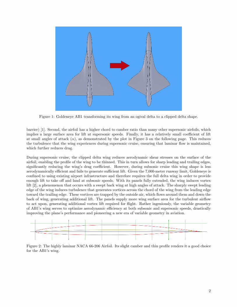
Figure 1: Goldeneye AB1 transforming its wing from an ogival delta to a clipped delta shape.
barrier) [1]. Second, the airfoil has a higher chord to camber ratio than many other supersonic airfoils, whichimplies a large surface area for lift at supersonic speeds. Finally, it has a relatively small coefficient of liftat small angles of attack (α), as demonstrated by the plot in Figure 3 on the following page. This reducesthe turbulence that the wing experiences during supersonic cruise, ensuring that laminar flow is maintained,which further reduces drag.
During supersonic cruise, the clipped delta wing reduces aerodynamic shear stresses on the surface of theairfoil, enabling the profile of the wing to be thinned. This in turn allows for sharp leading and trailing edges,significantly reducing the wing’s drag coefficient. However, during subsonic cruise this wing shape is lessaerodynamically efficient and fails to generate sufficient lift. Given the 7,000-meter runway limit, Goldeneye isconfined to using existing airport infrastructure and therefore requires the full delta wing in order to provideenough lift to take off and land at subsonic speeds. With its panels fully extended, the wing induces vortexlift [2], a phenomenon that occurs with a swept back wing at high angles of attack. The sharply swept leadingedge of the wing induces turbulence that generates vortices across the chord of the wing from the leading edgetoward the trailing edge. These vortices are trapped by the outside air, which flows around them and down theback of wing, generating additional lift. The panels supply more wing surface area for the turbulent airflowto act upon, generating additional vortex lift required for flight. Rather ingeniously, the variable geometryof AB1’s wing serves to optimize aerodynamic efficiency at both subsonic and supersonic speeds, drasticallyimproving the plane’s performance and pioneering a new era of variable geometry in aviation.
Figure 2: The highly laminar NACA 66-206 Airfoil. Its slight camber and thin profile renders it a good choicefor the AB1’s wing.
2
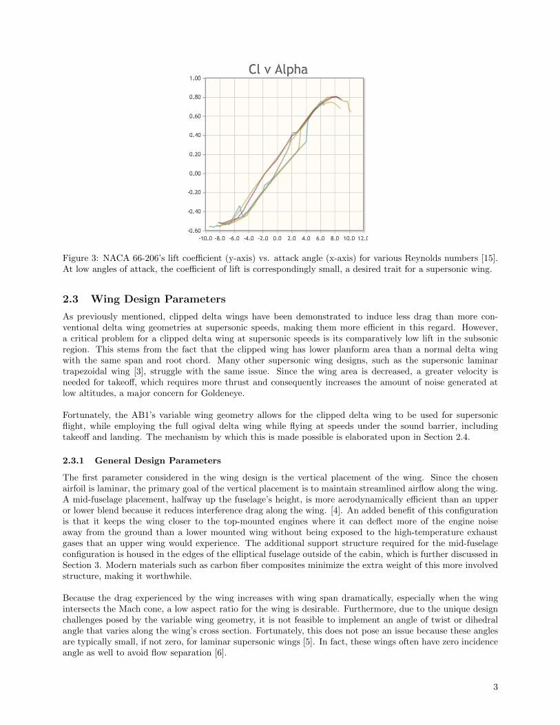
Figure 3: NACA 66-206’s lift coefficient (y-axis) vs. attack angle (x-axis) for various Reynolds numbers [15].At low angles of attack, the coefficient of lift is correspondingly small, a desired trait for a supersonic wing.
2.3 Wing Design Parameters
As previously mentioned, clipped delta wings have been demonstrated to induce less drag than more con-ventional delta wing geometries at supersonic speeds, making them more efficient in this regard. However,a critical problem for a clipped delta wing at supersonic speeds is its comparatively low lift in the subsonicregion. This stems from the fact that the clipped wing has lower planform area than a normal delta wingwith the same span and root chord. Many other supersonic wing designs, such as the supersonic laminartrapezoidal wing [3], struggle with the same issue. Since the wing area is decreased, a greater velocity isneeded for takeoff, which requires more thrust and consequently increases the amount of noise generated atlow altitudes, a major concern for Goldeneye.
Fortunately, the AB1’s variable wing geometry allows for the clipped delta wing to be used for supersonicflight, while employing the full ogival delta wing while flying at speeds under the sound barrier, includingtakeoff and landing. The mechanism by which this is made possible is elaborated upon in Section 2.4.
2.3.1 General Design Parameters
The first parameter considered in the wing design is the vertical placement of the wing. Since the chosenairfoil is laminar, the primary goal of the vertical placement is to maintain streamlined airflow along the wing.A mid-fuselage placement, halfway up the fuselage’s height, is more aerodynamically efficient than an upperor lower blend because it reduces interference drag along the wing. [4]. An added benefit of this configurationis that it keeps the wing closer to the top-mounted engines where it can deflect more of the engine noiseaway from the ground than a lower mounted wing without being exposed to the high-temperature exhaustgases that an upper wing would experience. The additional support structure required for the mid-fuselageconfiguration is housed in the edges of the elliptical fuselage outside of the cabin, which is further discussed inSection 3. Modern materials such as carbon fiber composites minimize the extra weight of this more involvedstructure, making it worthwhile.
Because the drag experienced by the wing increases with wing span dramatically, especially when the wingintersects the Mach cone, a low aspect ratio for the wing is desirable. Furthermore, due to the unique designchallenges posed by the variable wing geometry, it is not feasible to implement an angle of twist or dihedralangle that varies along the wing’s cross section. Fortunately, this does not pose an issue because these anglesare typically small, if not zero, for laminar supersonic wings [5]. In fact, these wings often have zero incidenceangle as well to avoid flow separation [6].
3
2.3.2 Oblique Shock
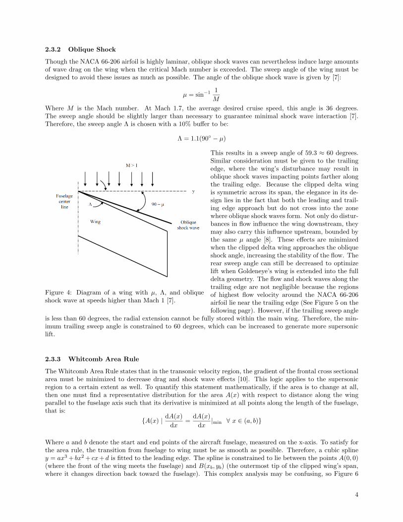
Though the NACA 66-206 airfoil is highly laminar, oblique shock waves can nevertheless induce large amountsof wave drag on the wing when the critical Mach number is exceeded. The sweep angle of the wing must bedesigned to avoid these issues as much as possible. The angle of the oblique shock wave is given by [7]:
µ = sin−1 1
M
Where M is the Mach number. At Mach 1.7, the average desired cruise speed, this angle is 36 degrees.The sweep angle should be slightly larger than necessary to guarantee minimal shock wave interaction [7].Therefore, the sweep angle Λ is chosen with a 10% buffer to be:
Λ = 1.1(90◦ − µ)
Figure 4: Diagram of a wing with µ, Λ, and obliqueshock wave at speeds higher than Mach 1 [7].
This results in a sweep angle of 59.3 ≈ 60 degrees.Similar consideration must be given to the trailingedge, where the wing’s disturbance may result inoblique shock waves impacting points farther alongthe trailing edge. Because the clipped delta wingis symmetric across its span, the elegance in its de-sign lies in the fact that both the leading and trail-ing edge approach but do not cross into the zonewhere oblique shock waves form. Not only do distur-bances in flow influence the wing downstream, theymay also carry this influence upstream, bounded bythe same µ angle [8]. These effects are minimizedwhen the clipped delta wing approaches the obliqueshock angle, increasing the stability of the flow. Therear sweep angle can still be decreased to optimizelift when Goldeneye’s wing is extended into the fulldelta geometry. The flow and shock waves along thetrailing edge are not negligible because the regionsof highest flow velocity around the NACA 66-206airfoil lie near the trailing edge (See Figure 5 on thefollowing pagr). However, if the trailing sweep angle
is less than 60 degrees, the radial extension cannot be fully stored within the main wing. Therefore, the min-imum trailing sweep angle is constrained to 60 degrees, which can be increased to generate more supersoniclift.
2.3.3 Whitcomb Area Rule
The Whitcomb Area Rule states that in the transonic velocity region, the gradient of the frontal cross sectionalarea must be minimized to decrease drag and shock wave effects [10]. This logic applies to the supersonicregion to a certain extent as well. To quantify this statement mathematically, if the area is to change at all,then one must find a representative distribution for the area A(x) with respect to distance along the wingparallel to the fuselage axis such that its derivative is minimized at all points along the length of the fuselage,that is:
{A(x) | dA(x)
dx=
dA(x)
dx|min ∀ x ∈ (a, b)}
Where a and b denote the start and end points of the aircraft fuselage, measured on the x-axis. To satisfy forthe area rule, the transition from fuselage to wing must be as smooth as possible. Therefore, a cubic spliney = ax3 + bx2 + cx+ d is fitted to the leading edge. The spline is constrained to lie between the points A(0, 0)(where the front of the wing meets the fuselage) and B(xb, yb) (the outermost tip of the clipped wing’s span,where it changes direction back toward the fuselage). This complex analysis may be confusing, so Figure 6
4
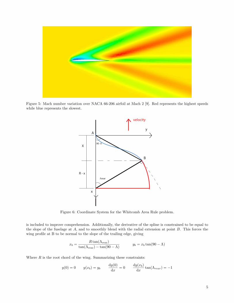
Figure 5: Mach number variation over NACA 66-206 airfoil at Mach 2 [9]. Red represents the highest speedswhile blue represents the slowest.
y
x
B
velocity
A
X
R - x
90 -Λ
Λrear
Figure 6: Coordinate System for the Whitcomb Area Rule problem.
is included to improve comprehension. Additionally, the derivative of the spline is constrained to be equal tothe slope of the fuselage at A, and to smoothly blend with the radial extension at point B. This forces thewing profile at B to be normal to the slope of the trailing edge, giving
xb =R tan(Λrear)
tan(Λrear)− tan(90− Λ)yb = xb tan(90− Λ)
Where R is the root chord of the wing. Summarizing these constraints:
y(0) = 0 y(xb) = ybdy(0)
dx= 0
dy(xb)
dxtan(Λrear) = −1
5
Solving the equations, the result is that c = d = 0 and:
[x3b x2
b
3x2b 2xb
] [ab
]=
[yb
1/ tan(Λrear)
]This provides a straightforward way to solve for the leading edge spline function with respect to the root chordand rear sweep angle. Now there is a solid framework to prototype the wing; the rear sweep angle can beincreased or decreased to optimize the subsonic lift (as it changes the area of the radial wing extension), andthe root chord can be increased to boost overall size and lift.
A well-documented benefit of highly swept wings is their induced dihedral effect, summarized succinctly:
“A swept wing produces a negative rolling moment because of a difference in velocitycomponents normal to the leading edge between the left and right wing sections,hence, a swept wing may not need a dihedral or anhedral to satisfy lateral-directionalstability requirements” [11].
2.3.4 Center of Pressure Optimization
There are a number of other perks generated by the ability to switch from a clipped delta to a full delta wingshape. One of these presents itself when tackling one of the major design concerns faced by the Concorde: itsshifting center of pressure. As aircraft velocity increases, the wing’s center of pressure shifts backward, towardthe trailing edge. As such, the center of pressure of the Concorde would shift around 6 feet between takeoff andsupersonic cruise [12]. To account for this, an elaborate fuel pumping control system was designed to distributefuel mass to move the center of gravity of the aircraft and maintain stability. This greatly complicated thedesign, increasing cost as well as necessitating the energy required to pump 20 tons of fuel around the plane.
This issue is circumvented by the variable wing geometry as the radial extension increases pressure nearthe trailing edge of the wing at low speeds, moving the center of pressure backward. Since the extensionretracts during supersonic flight, the loss of this added pressure offsets the natural rearward displacement ofthe pressure center at supersonic speeds. The result is a design that can be optimized to keep the center ofpressure in approximately the same location at both subsonic and supersonic velocities. Mathematically, thewing is designed such that: ∫∫
S1x · Psuper(x, y)dxdy∫∫
S1Psuper(x, y)dxdy
=
∫∫S2x · Psub(x, y)dxdy∫∫
S2Psub(x, y)dxdy
where Psuper and Psub are the pressure distributions along the wing at supersonic cruise and a representativesubsonic velocity, S1 is the clipped delta wing planform area, and S2 is the full delta planform area [13]. .
2.3.5 Thickness Ratio Optimization
Another benefit of the variable wing geometry is the opportunity to change the thickness ratio of the airfoil.Since the extension is stored within the wing, as soon as it is deployed, the hinges on the trailing edge of theclipped wing open to allow the extension to protrude farther (see Section 2.4). Therefore, the 6% thicknessratio of the NACA airfoil can be changed during subsonic flight. The ideal thickness ratio for that conditionis governed by the Torenbeek equation [14]:
t
c= 0.30
[(1−
(5 +M2
5 + (M∗)2
)3.5)√1−M2
M2
]2/3
Where tc is the thickness ratio, M is the Mach number, and M∗ is a constant unique to each airfoil profile.
This allows the extension-modified airfoil to have a thickness ratio optimized for any subsonic Mach number.
6
2.3.6 Wing Comparisons
One final comparison is noteworthy enough to be drawn between the proposed clipped delta wing, the Con-corde’s full delta wing, and the laminar trapezoidal wing of the Aerion and Boom supersonic aircraft. The fulldelta geometry of Goldeneye’s wing is extremely similar to the ogival delta wing of the Concorde. However, theConcorde’s wing is often categorized as a variable sweep wing, which struggled to balance supersonic and sub-sonic efficiency. The Aerion’s laminar trapezoidal supersonic wing provides less lift at subsonic speeds, whichbears responsibility for undesirable noise, runway, thrust and weight characteristics. However, the Aeriondemonstrates that, given a highly laminar airfoil, oblique shock waves are perhaps not quite as significant aconcern. This means that the front sweep angle can be tweaked as well in finalizing a scaled version of thewing to suit the lift requirements of the aircraft. Thus, Goldeneye’s variable geometry wing cleverly managesto capture the best of all worlds.
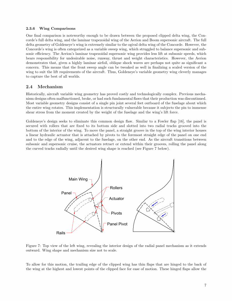
2.4 Mechanism
Historically, aircraft variable wing geometry has proved costly and technologically complex. Previous mecha-nism designs often malfunctioned, broke, or had such fundamental flaws that their production was discontinued.Most variable geometry designs consist of a single pin joint several feet outboard of the fuselage about whichthe entire wing rotates. This implementation is structurally vulnerable because it subjects the pin to immenseshear stress from the moment created by the weight of the fuselage and the wing’s lift force.
Goldeneye’s design seeks to eliminate this common design flaw. Similar to a Fowler flap [16], the panel issecured with rollers that are fixed to its bottom side and slotted into two radial tracks grooved into thebottom of the interior of the wing. To move the panel, a straight groove in the top of the wing interior housesa linear hydraulic actuator that is attached by pivots to the foremost straight edge of the panel on one endand to the edge of the wing, adjacent to the fuselage, on the other end. As the aircraft transitions betweensubsonic and supersonic cruise, the actuators retract or extend within their grooves, rolling the panel alongthe curved tracks radially until the desired wing shape is reached (see Figure 7 below).
Main Wing
Panel
Rails
Rollers
Pivots
Actuator
Panel Pivot
Figure 7: Top view of the left wing, revealing the interior design of the radial panel mechanism as it extendsoutward. Wing shape and mechanism size not to scale.
To allow for this motion, the trailing edge of the clipped wing has thin flaps that are hinged to the back ofthe wing at the highest and lowest points of the clipped face for ease of motion. These hinged flaps allow the
7
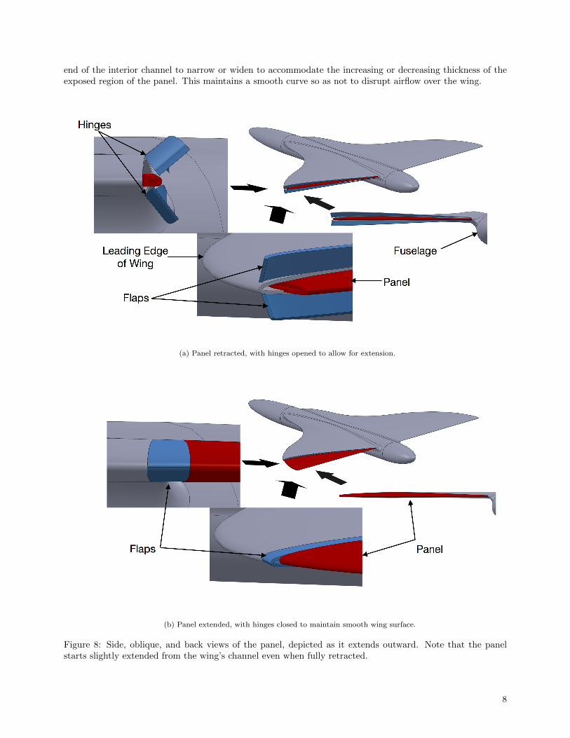
end of the interior channel to narrow or widen to accommodate the increasing or decreasing thickness of theexposed region of the panel. This maintains a smooth curve so as not to disrupt airflow over the wing.
(a) Panel retracted, with hinges opened to allow for extension.
(b) Panel extended, with hinges closed to maintain smooth wing surface.
Figure 8: Side, oblique, and back views of the panel, depicted as it extends outward. Note that the panelstarts slightly extended from the wing’s channel even when fully retracted.
8
To preserve the airfoil’s shape, the panel is designed such that it serves as the back of the airfoil when fullyextended, complementing the front of the airfoil from the fore region of the wing. This requires that thepanel’s airfoil axis be parallel to the fuselage’s when it is fully extended. Consequently, when the panel isfully retracted, its airfoil axis is offset from the fuselage’s by the angle between the trailing edge of the clippedwing and a line perpendicular to the fuselage. This issue is resolved by installing the panel such that it isalways at least slightly extended from the wing interior, even when retracted (See Figure 8 on the previouspage). It should be noted that the trailing edges of the main wing and panel remain adjacent when the panelis fully retracted, and that the hinged flaps lie just on top and bottom of the panel’s trailing edge in thisconfiguration. In this way, Goldeneye’s wings have a smooth, continuous airfoil at all times.
2.5 Control Surfaces
One of the main concerns arising from the use of variable geometry wings is how to implement the controlsurfaces that roll and pitch the aircraft. Conventionally, ailerons are mounted on the trailing edge of the wingto control the rolling moment. However, this configuration is only possible for Goldeneye during subsonic flight.This is because the radial panel is only extended at low speeds and ailerons may only be placed on the trailingedge of the panel since the main wing features hinged flaps that preserve the airfoil’s shape. While roll controlis most important during subsonic flight when AB1 does the majority of its maneuvering, it will spend muchtime at supersonic cruise, making it necessary to better control AB1’s unstable roll. To address this problem,inspiration can be gleaned from the Grumman F-14, a supersonic fighter jet with variable-sweep wings. Thisaircraft uses wing-mounted spoilers instead of ailerons to enable roll control, even during supersonic flight.However, the spoilers must be disabled if the plane’s sweep angle exceeds 57◦ [17]. Fortunately, Goldeneye’svariable geometry does not affect its sweep angle, allowing the installation of wing spoilers that are functionalduring both subsonic and supersonic flight.
The Concorde had the luxury of ailerons as a primary control surface, operating them differentially to generatea rolling moment and symmetrically for a pitching moment. Furthermore, it did not require a horizontalstabilizer due to the added stability of the delta wing at supersonic speeds. On the contrary, Goldeneye ismuch less horizontally sound during supersonic cruise because of its clipped delta wing, trading stability forreduced drag. Therefore, a separate mechanism is required for both horizontal stability and to control pitch,which the spoilers do not address. A canard seems to be the simplest and most effective way to achieve this,discussed further in Section 5.2.
2.6 Materials & Structure
The wing’s frame consists of tapered steel cross sections joined by two titanium spars. Its surface is coatedwith aluminum alloy 7075-O, a common industry-grade aviation material. The steel tracks for the extensionmechanism are attached to the wing’s cross-sections via titanium fasteners, atop which the radial panel rests.The panel is comprised of carbon composite cross sections united by a spar to reduce weight and is stored inthe empty space between the wing’s cross sections.
3 Fuselage
3.1 Cabin
The length and cross-sectional area of Goldeneye AB1’s cabin is dictated by the passenger load for which theplane is designed. Holding up to 12 passengers, Goldeneye’s cabin is an elliptical prism measuring 3 metersalong its major axis, 2.4 meters along its minor axis, and 10 meters in length, with a shell thickness of 2centimeters. The floor is positioned 2 meters (6.56 feet) below the apex of the cabin for optimal headroom.The elliptical cross section serves to maximize passenger space inside the cabin while still leaving space for themid-fuselage wing mount connections. In addition to providing more volume for storage of luggage and othercargo (relatively small loads for a business jet), this shape also provides for a more seamless integration withthe wing mount than with an upper or lower fuselage blend, which is not only more aesthetically pleasing butalso reduces interference drag due to the interaction of airflow streamlines between the wing and fuselage [19].
9
Underneath the cabin, AB1’s underbelly serves primarily as fuel storage. Because it is a business jet, Goldeneyeis not concerned with providing excess cargo space, though the very front of the underbelly features a sizablevolume for this purpose. Aft of this space, three equally sized fuel tanks line the rest of the underbelly,adjacent from front to back. The tanks are connected by valves to control the drainage rate. Normally, thetanks empty evenly in order to keep the plane’s center of gravity stable, but this can be adjusted accordinglyif need be.
3.2 Nose and Tail
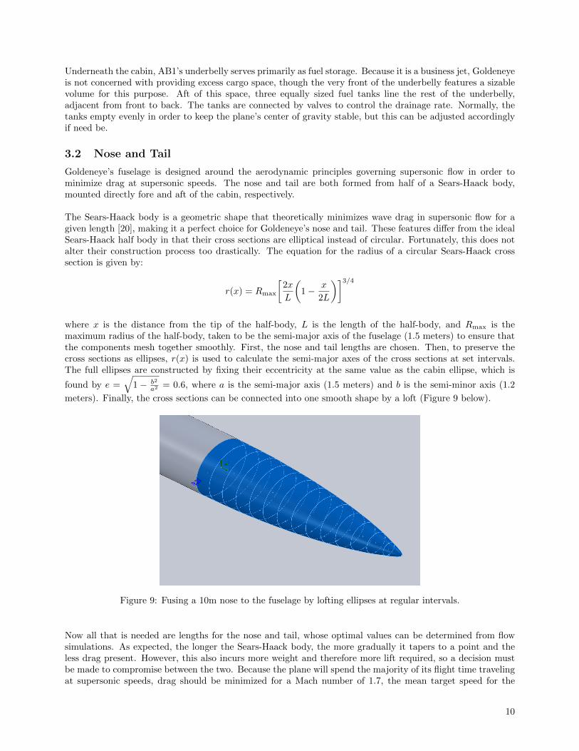
Goldeneye’s fuselage is designed around the aerodynamic principles governing supersonic flow in order tominimize drag at supersonic speeds. The nose and tail are both formed from half of a Sears-Haack body,mounted directly fore and aft of the cabin, respectively.
The Sears-Haack body is a geometric shape that theoretically minimizes wave drag in supersonic flow for agiven length [20], making it a perfect choice for Goldeneye’s nose and tail. These features differ from the idealSears-Haack half body in that their cross sections are elliptical instead of circular. Fortunately, this does notalter their construction process too drastically. The equation for the radius of a circular Sears-Haack crosssection is given by:
r(x) = Rmax
[2x
L
(1− x
2L
)]3/4
where x is the distance from the tip of the half-body, L is the length of the half-body, and Rmax is themaximum radius of the half-body, taken to be the semi-major axis of the fuselage (1.5 meters) to ensure thatthe components mesh together smoothly. First, the nose and tail lengths are chosen. Then, to preserve thecross sections as ellipses, r(x) is used to calculate the semi-major axes of the cross sections at set intervals.The full ellipses are constructed by fixing their eccentricity at the same value as the cabin ellipse, which is
found by e =√
1− b2
a2 = 0.6, where a is the semi-major axis (1.5 meters) and b is the semi-minor axis (1.2
meters). Finally, the cross sections can be connected into one smooth shape by a loft (Figure 9 below).
Figure 9: Fusing a 10m nose to the fuselage by lofting ellipses at regular intervals.
Now all that is needed are lengths for the nose and tail, whose optimal values can be determined from flowsimulations. As expected, the longer the Sears-Haack body, the more gradually it tapers to a point and theless drag present. However, this also incurs more weight and therefore more lift required, so a decision mustbe made to compromise between the two. Because the plane will spend the majority of its flight time travelingat supersonic speeds, drag should be minimized for a Mach number of 1.7, the mean target speed for the
10
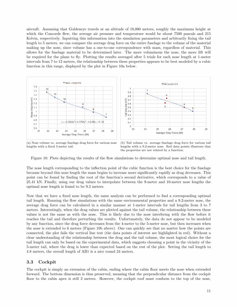
aircraft. Assuming that Goldeneye travels at an altitude of 18,000 meters, roughly the maximum height atwhich the Concorde flew, the average air pressure and temperature would be about 7500 pascals and 215Kelvin, respectively. Inputting this information into the simulation parameters and arbitrarily fixing the taillength to 5 meters, we can compare the average drag force on the entire fuselage to the volume of the materialmaking up the nose, since volume has a one-to-one correspondence with mass, regardless of material. Thisallows for the fuselage material to be determined later. The more voluminous the nose, the more lift willbe required for the plane to fly. Plotting the results averaged after 5 trials for each nose length at 1-meterintervals from 7 to 12 meters, the relationship between these properties appears to be best modeled by a cubicfunction in this range, displayed by the plot in Figure 10a below.
(a) Nose volume vs. average fuselage drag force for various noselengths with a fixed 5-meter tail.
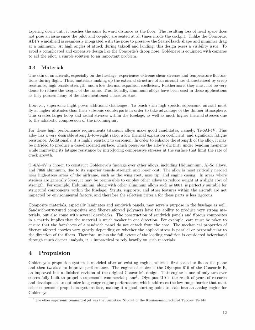
(b) Tail volume vs. average fuselage drag force for various taillengths with a 9.2-meter nose. Red data points illustrate thatthe properties are not related by a function.
Figure 10: Plots depicting the results of the flow simulations to determine optimal nose and tail length.
The nose length corresponding to the inflection point of the cubic function is the best choice for the fuselagebecause beyond this nose length the mass begins to increase more significantly rapidly as drag decreases. Thispoint can be found by finding the root of the function’s second derivative, which corresponds to a value of25.41 kN. Finally, using our drag values to interpolate between the 9-meter and 10-meter nose lengths theoptimal nose length is found to be 9.2 meters.
Now that we have a fixed nose length, the same analysis can be performed to find a corresponding optimaltail length. Running the flow simulations with the same environmental properties and a 9.2-meter nose, theaverage drag force can be calculated in a similar manner at 1-meter intervals for tail lengths from 3 to 7meters. Interestingly, when the drag values are plotted against the tail volume, the relationship between thesevalues is not the same as with the nose. This is likely due to the nose interfering with the flow before itreaches the tail and therefore perturbing the results. Unfortunately, the data do not appear to be modeledby any function, since the drag force decreases from the 4-meter to the 5-meter nose, but then increases whenthe nose is extended to 6 meters (Figure 10b above). One can quickly see that no matter how the points areconnected, the plot fails the vertical line test (the data points of interest are highlighted in red). Without aclear understanding of the relationship between the drag and the tail volume, the most logical choice for thetail length can only be based on the experimental data, which suggests choosing a point in the vicinity of the5-meter tail, where the drag is lower than expected based on the rest of the plot. Setting the tail length to4.8 meters, the overall length of AB1 is a nice round 24 meters.
3.3 Cockpit
The cockpit is simply an extension of the cabin, ending where the cabin floor meets the nose when extendedforward. The bottom dimension is thus preserved, meaning that the perpendicular distance from the cockpitfloor to the cabin apex is still 2 meters. However, the cockpit roof must conform to the top of the nose,
11
tapering down until it reaches the same forward distance as the floor. The resulting loss of head space doesnot pose an issue since the pilot and co-pilot are seated at all times inside the cockpit. Unlike the Concorde,AB1’s windshield is seamlessly integrated with the nose to preserve the Sears-Haack shape and minimize dragat a minimum. At high angles of attack during takeoff and landing, this design poses a visibility issue. Toavoid a complicated and expensive design like the Concorde’s droop nose, Goldeneye is equipped with camerasto aid the pilot, a simple solution to an important problem.
3.4 Materials
The skin of an aircraft, especially on the fuselage, experiences extreme shear stresses and temperature fluctua-tions during flight. Thus, materials making up the external structure of an aircraft are characterized by creepresistance, high tensile strength, and a low thermal expansion coefficient. Furthermore, they must not be verydense to reduce the weight of the frame. Traditionally, aluminum alloys have been used in these applicationsas they possess many of the aforementioned characteristics.
However, supersonic flight poses additional challenges. To reach such high speeds, supersonic aircraft mustfly at higher altitudes than their subsonic counterparts in order to take advantage of the thinner atmosphere.This creates larger hoop and radial stresses within the fuselage, as well as much higher thermal stresses dueto the adiabatic compression of the incoming air.
For these high performance requirements titanium alloys make good candidates, namely, Ti-6Al-4V. Thisalloy has a very desirable strength-to-weight ratio, a low thermal expansion coefficient, and significant fatigueresistance. Additionally, it is highly resistant to corrosion. In order to enhance the strength of the alloy, it maybe nitrided to produce a case-hardened surface, which preserves the alloy’s ductility under bending momentswhile improving its fatigue resistance by introducing compressive stresses at the surface that limit the rate ofcrack growth.
Ti-6Al-4V is chosen to construct Goldeneye’s fuselage over other alloys, including Hiduminium, Al-Sc alloys,and 7068 aluminum, due to its superior tensile strength and lower cost. The alloy is most critically needednear high-stress areas of the airframe, such as the wing root, nose tip, and engine casing. In areas wherestresses are generally lower, it may be permissible to employ other alloys to reduce weight at a slight cost ofstrength. For example, Hiduminium, along with other aluminum alloys such as 6061, is perfectly suitable forstructural components within the fuselage. Struts, supports, and other features within the aircraft are notimpacted by environmental factors, and therefore the selection criteria for these parts is less rigorous.
Composite materials, especially laminates and sandwich panels, may serve a purpose in the fuselage as well.Sandwich-structured composites and fiber-reinforced polymers have the ability to produce very strong ma-terials, but also come with several drawbacks. The construction of sandwich panels and fibrous compositesin a matrix implies that the material is much weaker in one direction. For example, care must be taken toensure that the facesheets of a sandwich panel do not detach from the core. The mechanical properties offiber-reinforced epoxies vary greatly depending on whether the applied stress is parallel or perpendicular tothe direction of the fibers. Therefore, unless the full extent of the loading condition is considered beforehandthrough much deeper analysis, it is impractical to rely heavily on such materials.
4 Propulsion
Goldeneye’s propulsion system is modeled after an existing engine, which is first scaled to fit on the planeand then tweaked to improve performance. The engine of choice is the Olympus 610 of the Concorde B,an improved but unfinished revision of the original Concorde’s design. This engine is one of only two eversuccessfully built to propel a supersonic commercial plane1. Olympus 610 is the result of years of researchand development to optimize long-range engine performance, which addresses the low-range barrier that mostother supersonic propulsion systems face, making it a good starting point to scale into an analog engine forGoldeneye.
1The other supersonic commercial jet was the Kuznetsov NK-144 of the Russian-manufactured Tupolev Tu-144
12
4.1 Engine Dimensions & Supersonic Thrust Calculations
A number of scaling arguments are used to tailor the Olympus engine to Goldeneye’s fuselage and wings.Given the much smaller size of the plane relative to the Concorde, a two-engine setup makes the most senseas opposed to the Concorde’s four-engine layout.
The following arguments are included to mathematically justify the engine scaling process [21]:
s =Treqd
TdataLreqd = Ldata · s0.4 Dreqd = Ddata · s0.5 Wreqd = Wdata · s1.1
s ≡ Scale Factor L ≡ Engine LengthD ≡ Engine Diameter W ≡ Engine WeightT ≡ Thrust
where the subscript reqd represents values for Goldeneye’s engine and data represents values for the Olympusengine.
To calculate the dimensions of the scaled engine, an estimate of the thrust during level flight is required, whichcan be found by [23]:
Treqd =W
CL/CD
where CL is the lift coefficient and CD is the drag coefficient.
To account for deviations from the ideal conditions that the previous equations assume (a constant dragforce that does not account for the plane’s acceleration), the theoretical required thrust is calculated for theConcorde. Observing that this formula underestimates the required thrust by 11.98%, a correction can bemade to more accurately calculate Goldeneye’s required thrust:
Treqd = 1.1198 · W
CL/CD
Because Goldeneye’s weight is a bit vague due to different materials considerations, it is a good idea to use asimilarly sized subsonic plane, the Gulfstream G280 [24], to provide an upper bound for Goldeneye’s weight(18000 kg). The coefficient of lift (0.125) and drag (0.0175) are taken from the Concorde’s supersonic cruise asa worst-case estimate, since the fuselage and wings of Goldeneye are more optimized for streamlined flight thanthe Concorde’s. Plugging these numbers in, it is calculated that Treqd = 21722 N and therefore both enginesmust supply at least half this thrust, 10861 N. Finally, with this value the scaling factor and specifications ofthe engine are found to be:
s = 0.2395 Lreqd = 3.34 m Dreqd = 0.684 m Wreqd = 660 kg
where Lreqd, Dreqd, Wreqd are the length, diameter and weight of each engine, respectively.
4.2 Afterburner Performance
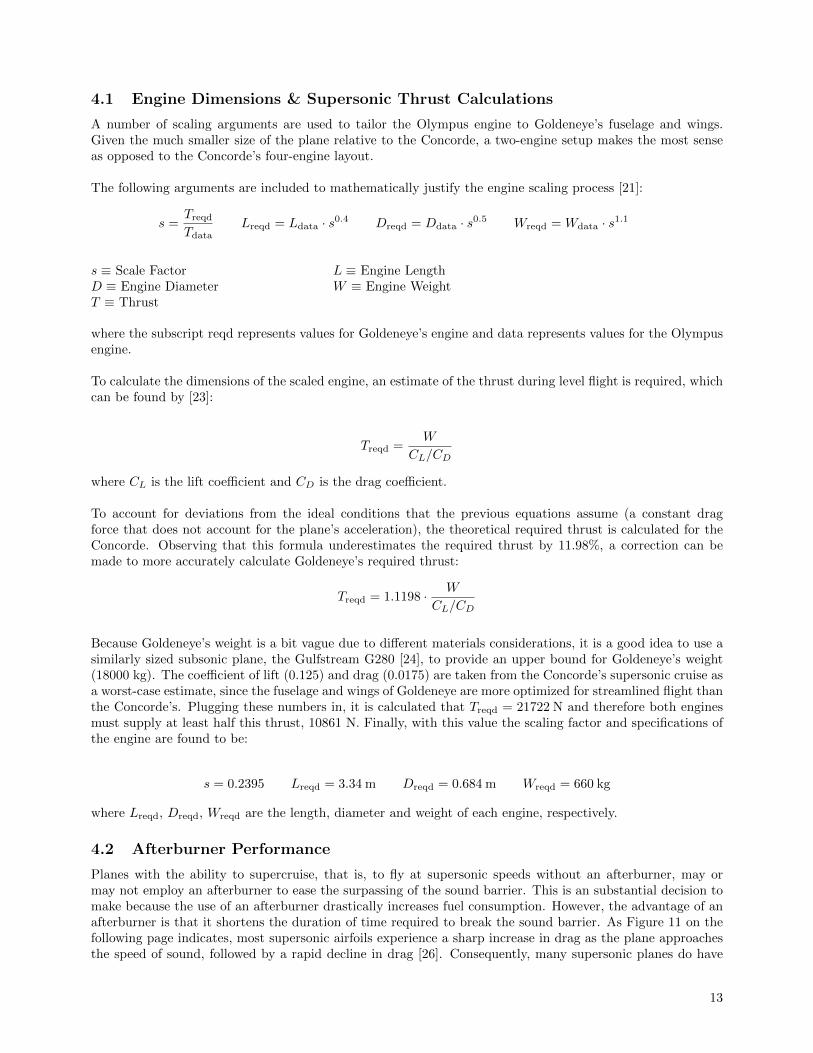
Planes with the ability to supercruise, that is, to fly at supersonic speeds without an afterburner, may ormay not employ an afterburner to ease the surpassing of the sound barrier. This is an substantial decision tomake because the use of an afterburner drastically increases fuel consumption. However, the advantage of anafterburner is that it shortens the duration of time required to break the sound barrier. As Figure 11 on thefollowing page indicates, most supersonic airfoils experience a sharp increase in drag as the plane approachesthe speed of sound, followed by a rapid decline in drag [26]. Consequently, many supersonic planes do have
13
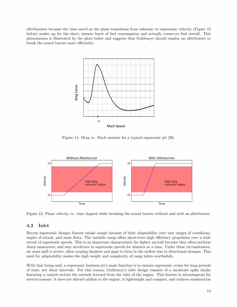
afterburners because the time saved as the plane transitions from subsonic to supersonic velocity (Figure 12below) makes up for the short, intense burst of fuel consumption and actually conserves fuel overall. Thisphenomenon is illustrated by the plots below and suggests that Goldeneye should employ an afterburner tobreak the sound barrier more efficiently.
Figure 11: Drag vs. Mach number for a typical supersonic jet [26].
Figure 12: Plane velocity vs. time elapsed while breaking the sound barrier without and with an afterburner.
4.3 Inlet
Recent supersonic designs feature intake ramps because of their adaptability over vast ranges of conditions,angles of attack, and mass flows. The variable ramp offers short-term high efficiency propulsion over a wideextent of supersonic speeds. This is an important characteristic for fighter aircraft because they often performsharp maneuvers, and may accelerate to supersonic speeds for minutes at a time. Under these circumstances,air mass spill is severe, often causing shadows and gaps to form in the airflow due to directional changes. Thisneed for adaptability makes the high weight and complexity of ramp inlets worthwhile.
With that being said, a supersonic business jet’s main function is to sustain supersonic cruise for long periodsof time, not short intervals. For this reason, Goldeneye’s inlet design consists of a moderate spike intakefeaturing a conical section the extends forward from the inlet of the engine. This feature is advantageous forseveral reasons: it does not disturb airflow to the engine, is lightweight and compact, and reduces construction
14
and maintenance costs. Furthermore, while it may be extensive, because the ducting’s sole purpose is toseparate the interior and exterior flow, the engine can be quite lengthy without significant increases in dragor weight.
The inlet resembles those of the MiG-21 or SR-71 engines, so the forward end of the engine can be modelledas a cylinder with a conical spike. Though past aircraft with engines situated inside the fuselage (such asthe Mach-2-capable English Electric Lightning) have used the cone to store radar equipment, Goldeneye’sis hollow for weight reduction. In addition, the radar’s performance is heightened when it is placed fatherforward in the aircraft. A simple translational mechanism moves the cone back and forth to adjust the intakecross section. To provide a shallow angle of attack, the cone length is 3 meters and cone radius is 0.335 meters,which is almost completely inside of the 4-meter long ducting area when retracted. At subsonic speeds, theretracted cone compresses the mass that flows into the frontal section, which then passes into the engine cycle.This allows for high total pressure recovery and inlet efficiency, as defined below [49]:
PR, tot(M < 1) =Pf
P∞η =
Pf
Pi
Pi ≡ Intake Pressure Pf ≡ Exhaust Nozzle PressurePR, tot ≡ Total Pressure Recovered η ≡ EfficiencyP∞ ≡ Free Stream Pressure M ≡ Mach Number
For aircraft velocities less than Mach 1, Pf ≈ Pi. Conversely, at velocities greater than Mach 1, the coneextends to decrease the bypass ratio and optimize the lead shock position. This decelerates the intake airspeed over the subsequent series of shocks, which reduces the total pressure recovery to the following relation:
PR,tot(M > 1) = η[1− 0.075(M − 1)1.35]
It is clear that below Mach 2, corresponding to the N+1 and N+2 NASA Current Technology Goals forFuture Supersonic Vehicles, this accounts for a small loss in pressure recovery. The second main propulsionperformance reduction is due to spillage drag, which occurs when an inlet spills air around the lip instead ofconducting it to the pressure face, as defined below:
Dspill = K[m(Vi − Vf) +A(Pi − P∞)
]where K is the lip suction factor, m is the mass flow rate, Vi − Vf is the velocity change upon entering theinlet, and A is the inlet’s cross sectional area. The relevant point is that the small engine dimensions requirea small inlet frontal area, which decreases the spillage drag contribution.
Many design features from the past reappear on Goldeneye’s engines to optimize performance. Cowl bleedsredirect incoming air through shock traps to provide subsonic cooling air to the rest of the engine, later drawnout of the nacelle by the fast-moving exhaust flowing through the ejector. For take-off and landing, whereM < 0.5, multiple ports open along the nacelle to bring air at ambient temperature and pressure to the enginecomponents through valves exposed to heat exchangers [50], which consist of tubular-array and micro-channelplate configurations of coolant-carrying pipes. Recent efforts, most notably Reaction Engine’s SABRE en-gine [51–54], have been able to reliably construct pre-cooler devices2 composed of thousands of thin-walled,small-diameter tubes, which provide large surface area and low weight, made possible by advances in indus-trial micrometer construction. The open ports take advantage of the low pressure in the bypass channel todraw air through the tube arrays, which is chilled by small volumes of rapidly cycling coolant, decreasingthe temperature of the air that is subsequently used to draw heat from the engine. This optimizes engine
2The most advanced pre-cooler devices cool intake air for hypersonic aircraft travelling at M ≥ 5; A similar construction wouldbe much more effective for cooling air of lower temperatures during takeoff and landing.
15
performance, which is beneficial for a high climbing rate out of a commercial airport with physical limitations3.
4.4 Exhaust Nozzles
Turbojet engines offer a significant improvement over turbofans at speeds greater than Mach 1.5. Theycompress the entirety of the intake flow into the core, which is then energized and exhausted at high velocityand temperature to produce pure thrust. The Rolls-Royce/Snecma Olympus 593 engine took advantage of thehigh-speed cruise benefits of the turbojet, rendering the Concorde’s propulsion as efficient as possible underthe technical limitations of the time, and echoed later in the Pratt & Whitney F119 and General Electric F120[33]. With that being said, turbofan engines excel in the high subsonic and low supersonic range, bestowinggreater cruise efficiency to the design along with quieter takeoff acceleration4. Thus, for an adaptable andcommercially practical supersonic business jet like Goldeneye, an engine that acts as both a turbofan andturbojet is optimal.
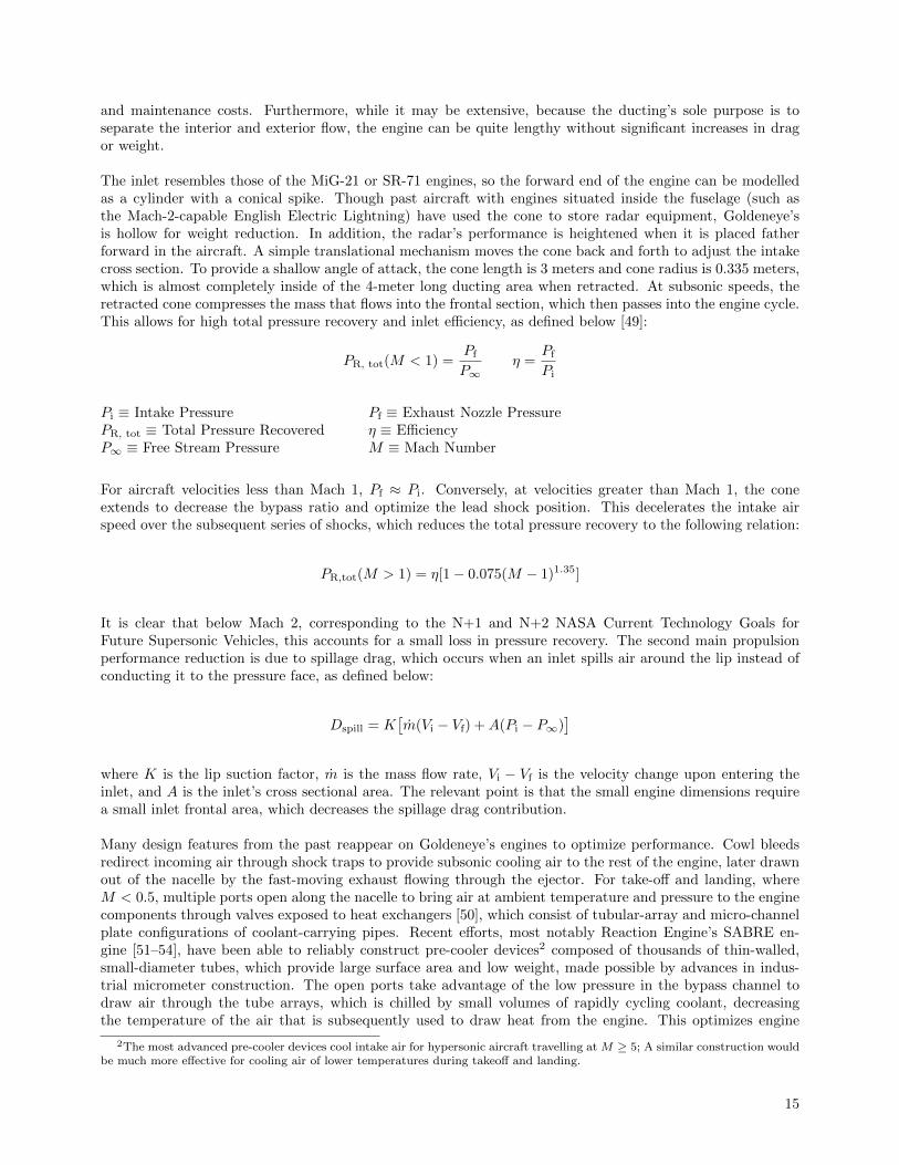
Debiasi and Papamoschou present a Targeted Mach Wave Elimination (TMWE) bypass design [31] thatcouples the core exhaust with a variable secondary bypass flow. This shields the mach waves produced by theturbulent eddies during the interaction of the exhaust stream with the environment, accompanied by primarybypass flow with a high bypass ratio (BPR). When the aircraft is in the subsonic and low supersonic segmentsof flight5, the bypass gates (labeled A in Figure 13 below) are opened, increasing the BPR to provide greaterlift.
Figure 13: Diagram of the engine when the relative ambient airflow (∞) is at M ≤ 1.5. A labels the retracted gates,which allow flow to the bypass chambers, B is the primary bypass path, and C is the mixing of the core flow andprimary bypass flow. Turbulent eddies travelling along E produce Mach waves along F. The secondary bypass flow atD suppresses the descending Mach waves at G.
3For example, San Diego International Airport has multiple restrictions due to topographical features that necessitate a steepclimb rate, preventing heavier aircraft from landing.
4This is achieved by accelerating a larger mass flow at lower speed.5From takeoff (M = 0) to transonic acceleration (M ≈ 1.5).
16
The intake stream is then separated into core and bypass flow, the latter of which is subdivided further intoa primary and secondary stream with a B:D ratio of 1.5, so that 40% of the bypass is redirected for targetednoise suppression while 60% is harnessed to increase thrust. mp and ms
6 are manipulated by compression andexpansion completely independently, allowing the velocity difference ∆U between Ucore and Up to be maxi-mized for optimal thrust. However, the ∆U between Ucore and Us is moderate, acting as a mediator betweenthe core flow and the ambient flow while simultaneously suppressing the Mach waves created by the mixingof the core and primary bypass streams. This concept is put into practice with a primary nozzle placed wherethese two flows mix and with a secondary nozzle where the exhausts of the primary nozzle and the secondarybypass flows mix.
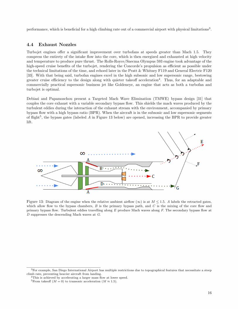
Debiasi and Papamoschou also show experimentally that coaxial7 eccentric8 nozzles are effective in mitigatingdownward noise originating from the elongated core of a turbojet engine [34–37]. Below, Figure 14 depicts thesecondary flow D exhausting from the secondary nozzle and the shielding in the G region from the noise sourceregion C. Because the secondary stream, whose velocity is closer to that of the surrounding flow, physicallyinterferes with the mach waves, the noise is dampened and redirected such that the noise distribution withrespect to arc angle has lower kurtosis9. The noise is therefore more evenly dissipated at lower amplitude overa large angular range, replacing the piercing scream of the turbojet with a rumble indistinguishable from otheraircraft sporting turbofan engines. This is shown in Fig. 8a of [31] (not displayed). Scale model testing showsa 17% (119 to 98 dB) reduction in noise of peak noise emissions directly behind the aircraft over frequenciesgreater than 50 Hz, and a 3.03% (99 to 96 dB) to 9.24% (106 to 98 dB) reduction in the lateral direction from500 to 2000Hz for an A-weighted spectrum10.
Figure 14: A simplistic diagram of the exhaust nozzles of an en-gine, as viewed from behind the aircraft. The letters correspondto Figure 13; B is the primary bypass, which mixes with thecore flow at C. The geometry here need not be concentric, butmust be designed for optimal BRP and thrust performance atsubsonic and low-supersonic ambient airspeeds. The secondarybypass flow, D, then mixes with the exhaust of the primarynozzle and is directed downwards since δv > δh, suppressing theMach waves in the G region.
The derivation of the thrust for the TMWE design in [31] follows the Hill & Peterson approach to thermody-namic analysis [38] and non-dimensionalizes the mass flow rates in each engine component11. The total thrustof the engine is given by equation 25 of [31]:
Ftot = Fp + Fs = mpUp +Ap(pp − p∞) + msUs +As(ps − p∞)− m∞U∞p ≡ Primary Nozzle Exhaust s ≡ Secondary AirflowF ≡ Thrust m ≡ Mass FlowA ≡ Area P ≡ Pressureρ ≡ Density U ≡ Velocity
6B:D = mp:ms, where mp ≡ primary bypass mass flow rate, and ms ≡ secondary bypass mass flow rate.7The primary nozzle is encompassed in the secondary nozzle, and often releases exhaust before the secondary nozzle.8Nozzle design featuring an off-center alignment between the two coaxial nozzles along one axis. In figure 14, the primary
nozzle is shifted vertically with respect to the secondary nozzle.9While kurtosis is not a measurement of the flatness, sharpness, or modality of a curve (as it is sometimes misinterpreted to
be), the dominant skewer of the noise distribution for a standard turbojet is not present when compared to designs featuringTMWE [31]. This means that the noise is evenly distributed at the tails of the curve, as it is in the center, and implies noisedissipation in all directions [46, 47].
10A noise spectrum perceived by the human ear11“To compare results relative to different cycles adopting the same engine core, it is proper to non-dimensionalize the mass
flow rates in each engine component with respect to the mass flow rate in the compressor.” [31]
17
The surface areas A of the nozzles, considered over a vertical plane, are defined by eqns. 23 and 24 of [31]:
Ap =mp
ρpUp=mcommrp
ρpUp
As =ms
ρsUs=mcommrs
ρsUs
where com represents the compressor. Pressure is calculated by P = ρRT , where ρ = mv is the density, R is
the gas constant, and T is the temperature at the location of interest. The nozzle exit velocity is defined byequation 22 of [31], U = M
√γRT , where M is the Mach number and γ = cp/cv is the specific heat ratio. The
corrected compressible mass flow rate is then given by equation 1 of [39]:
m =APtot√Ttot
√γ
RM
(1 +
γ − 1
2M2
)− γ + 12(γ − 1)
Alternatively, the corrected compressible mass flow rate, equation 2 of [39], can be found by dividing by afactor of g = 9.81 m/s2 and by considering the temperature ratio, Θ = T
T∞, and the pressure ratio, δ = P
P∞,
yielding: m =W√
Θt
gAδt, which for air computes to:
m =1
g0.59352M(1 + 0.2M2)−1ζm
kg
s m2
where ζm = 70.3069 lbs in2
s m2
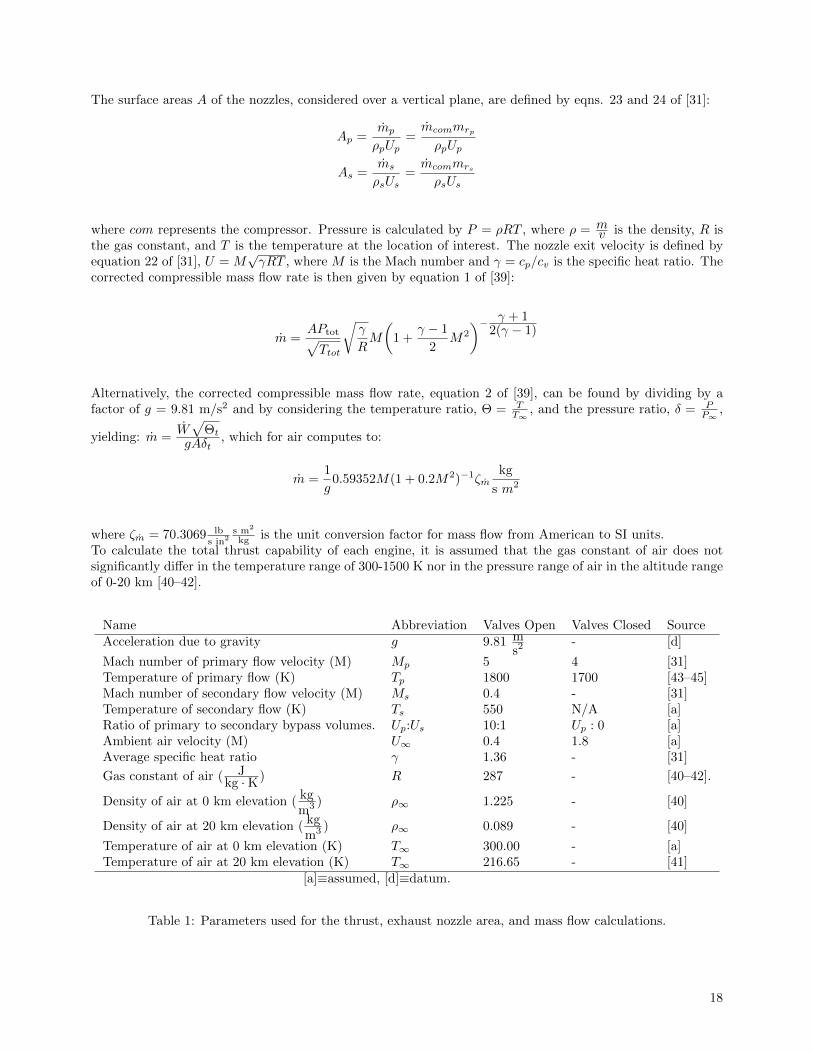
kg is the unit conversion factor for mass flow from American to SI units.To calculate the total thrust capability of each engine, it is assumed that the gas constant of air does notsignificantly differ in the temperature range of 300-1500 K nor in the pressure range of air in the altitude rangeof 0-20 km [40–42].
Name Abbreviation Valves Open Valves Closed SourceAcceleration due to gravity g 9.81 m
s2 - [d]
Mach number of primary flow velocity (M) Mp 5 4 [31]Temperature of primary flow (K) Tp 1800 1700 [43–45]Mach number of secondary flow velocity (M) Ms 0.4 - [31]Temperature of secondary flow (K) Ts 550 N/A [a]Ratio of primary to secondary bypass volumes. Up:Us 10:1 Up : 0 [a]Ambient air velocity (M) U∞ 0.4 1.8 [a]Average specific heat ratio γ 1.36 - [31]
Gas constant of air ( Jkg ·K) R 287 - [40–42].
Density of air at 0 km elevation (kgm3 ) ρ∞ 1.225 - [40]
Density of air at 20 km elevation (kgm3 ) ρ∞ 0.089 - [40]
Temperature of air at 0 km elevation (K) T∞ 300.00 - [a]Temperature of air at 20 km elevation (K) T∞ 216.65 - [41]
[a]≡assumed, [d]≡datum.
Table 1: Parameters used for the thrust, exhaust nozzle area, and mass flow calculations.
18
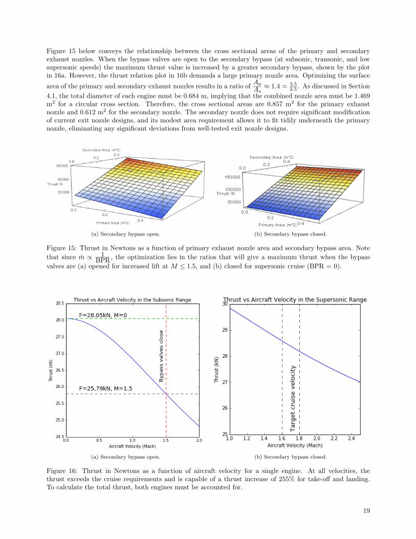
Figure 15 below conveys the relationship between the cross sectional areas of the primary and secondaryexhaust nozzles. When the bypass valves are open to the secondary bypass (at subsonic, transonic, and lowsupersonic speeds) the maximum thrust value is increased by a greater secondary bypass, shown by the plotin 16a. However, the thrust relation plot in 16b demands a large primary nozzle area. Optimizing the surface
area of the primary and secondary exhaust nozzles results in a ratio ofAp
As≈ 1.4 = 3.5
2.5 . As discussed in Section
4.1, the total diameter of each engine must be 0.684 m, implying that the combined nozzle area must be 1.469m2 for a circular cross section. Therefore, the cross sectional areas are 0.857 m2 for the primary exhaustnozzle and 0.612 m2 for the secondary nozzle. The secondary nozzle does not require significant modificationof current exit nozzle designs, and its modest area requirement allows it to fit tidily underneath the primarynozzle, eliminating any significant deviations from well-tested exit nozzle designs.
(a) Secondary bypass open. (b) Secondary bypass closed.
Figure 15: Thrust in Newtons as a function of primary exhaust nozzle area and secondary bypass area. Note
that since m ∝ 1BPR, the optimization lies in the ratios that will give a maximum thrust when the bypass
valves are (a) opened for increased lift at M ≤ 1.5, and (b) closed for supersonic cruise (BPR = 0).
(a) Secondary bypass open. (b) Secondary bypass closed.
Figure 16: Thrust in Newtons as a function of aircraft velocity for a single engine. At all velocities, thethrust exceeds the cruise requirements and is capable of a thrust increase of 255% for take-off and landing.To calculate the total thrust, both engines must be accounted for.
19
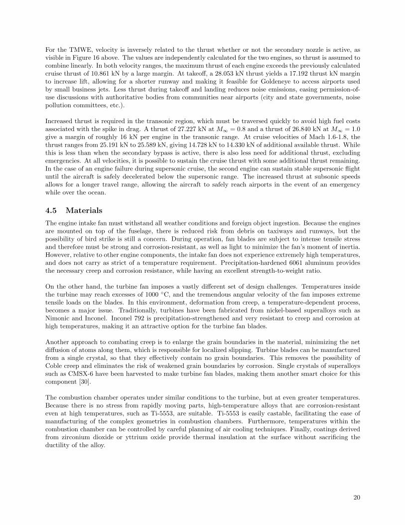
For the TMWE, velocity is inversely related to the thrust whether or not the secondary nozzle is active, asvisible in Figure 16 above. The values are independently calculated for the two engines, so thrust is assumed tocombine linearly. In both velocity ranges, the maximum thrust of each engine exceeds the previously calculatedcruise thrust of 10.861 kN by a large margin. At takeoff, a 28.053 kN thrust yields a 17.192 thrust kN marginto increase lift, allowing for a shorter runway and making it feasible for Goldeneye to access airports usedby small business jets. Less thrust during takeoff and landing reduces noise emissions, easing permission-of-use discussions with authoritative bodies from communities near airports (city and state governments, noisepollution committees, etc.).
Increased thrust is required in the transonic region, which must be traversed quickly to avoid high fuel costsassociated with the spike in drag. A thrust of 27.227 kN at M∞ = 0.8 and a thrust of 26.840 kN at M∞ = 1.0give a margin of roughly 16 kN per engine in the transonic range. At cruise velocities of Mach 1.6-1.8, thethrust ranges from 25.191 kN to 25.589 kN, giving 14.728 kN to 14.330 kN of additional available thrust. Whilethis is less than when the secondary bypass is active, there is also less need for additional thrust, excludingemergencies. At all velocities, it is possible to sustain the cruise thrust with some additional thrust remaining.In the case of an engine failure during supersonic cruise, the second engine can sustain stable supersonic flightuntil the aircraft is safely decelerated below the supersonic range. The increased thrust at subsonic speedsallows for a longer travel range, allowing the aircraft to safely reach airports in the event of an emergencywhile over the ocean.
4.5 Materials
The engine intake fan must withstand all weather conditions and foreign object ingestion. Because the enginesare mounted on top of the fuselage, there is reduced risk from debris on taxiways and runways, but thepossibility of bird strike is still a concern. During operation, fan blades are subject to intense tensile stressand therefore must be strong and corrosion-resistant, as well as light to minimize the fan’s moment of inertia.However, relative to other engine components, the intake fan does not experience extremely high temperatures,and does not carry as strict of a temperature requirement. Precipitation-hardened 6061 aluminum providesthe necessary creep and corrosion resistance, while having an excellent strength-to-weight ratio.
On the other hand, the turbine fan imposes a vastly different set of design challenges. Temperatures insidethe turbine may reach excesses of 1000 ◦C, and the tremendous angular velocity of the fan imposes extremetensile loads on the blades. In this environment, deformation from creep, a temperature-dependent process,becomes a major issue. Traditionally, turbines have been fabricated from nickel-based superalloys such asNimonic and Inconel. Inconel 792 is precipitation-strengthened and very resistant to creep and corrosion athigh temperatures, making it an attractive option for the turbine fan blades.
Another approach to combating creep is to enlarge the grain boundaries in the material, minimizing the netdiffusion of atoms along them, which is responsible for localized slipping. Turbine blades can be manufacturedfrom a single crystal, so that they effectively contain no grain boundaries. This removes the possibility ofCoble creep and eliminates the risk of weakened grain boundaries by corrosion. Single crystals of superalloyssuch as CMSX-6 have been harvested to make turbine fan blades, making them another smart choice for thiscomponent [30].
The combustion chamber operates under similar conditions to the turbine, but at even greater temperatures.Because there is no stress from rapidly moving parts, high-temperature alloys that are corrosion-resistanteven at high temperatures, such as Ti-5553, are suitable. Ti-5553 is easily castable, facilitating the ease ofmanufacturing of the complex geometries in combustion chambers. Furthermore, temperatures within thecombustion chamber can be controlled by careful planning of air cooling techniques. Finally, coatings derivedfrom zirconium dioxide or yttrium oxide provide thermal insulation at the surface without sacrificing theductility of the alloy.
20
5 Design Implementation
5.1 Wing Size
The wing’s geometry was parameterized in Section 2.3 with the outline of a planform wing shape based onthe root chord-length (R), the leading edge’s sweep angle (Λ), and the trailing edge’s sweep angle (Λrear). Toproduce a final wing shape and size, these parameters must be varied to create the optimal conditions forboth supersonic cruise and subsonic flight. As previously discussed, the optimal leading and trailing sweepangles are set to Λ = 60◦andΛrear = 60◦. A decrease in the leading angle results in a higher aspect ratio andprovides more lift at the expense of the leading edge crossing paths with oblique shock waves. An increaseof the trailing angle also increases the clipped delta wing surface area for lift during supersonic flight, butdecreases the size of the radial extension, thus diminishing subsonic flight performance. After conducting 25flow simulations at both supersonic cruise and standard temperature and pressure (STP) conditions, it wasdiscovered that compromises to either of the angles are not necessary to enable highly efficient supersonicflight.
The behaviour of laminar airfoils is analogous to that of the centerboard or keel of a sailboat; the flow aroundthem is streamlined and relatively symmetrical, especially in comparison to a conventional airfoil. As such itwill not provide much lift when its angle of attack is set to zero. However, if rotated even very slightly, theairfoil strongly counters this force. To study this behaviour, prototypes with root chord lengths varying from8 to 20 meters can be subjected to Mach 1.7 airflow at small incidence angles ranging from 0 to 3 degreesin the flow simulator. To validate this approach, a replica CAD of the Concorde’s wing is built and rununder the same simulations. When the results are compared to known Concorde specifications, the model’snumerical findings do not correlate perfectly with validated data, but they do follow the expected generaltrends previously discussed.
This paper only outlines a conceptual design of Goldeneye AB1, so certain approximations must be made inorder to use the fully loaded aircraft mass figure. The Gulfstream G280 is chosen as a reference aircraft forthis purpose. Its maximum load mass is 17962.2 kg, corresponding to a weight of 176030 N. As the G280 isdesigned to carry 20 passengers—8 more than the AB1—over similar ranges to Goldeneye, an absolute upperbound of the AB1’s load capacity is taken to be approximately 75% of the Gulfstream’s weight, a figure thataccounts for AB1’s smaller size, lighter materials, and larger fuel capacity. The lift is found in general toincrease exponentially as a function of incidence angle, and approximately linearly for small incidence angles.Testing various wing sizes at flow incidence angles between 0.5◦ and 1.7◦, enough lift is generated to reliablycarry AB1’s upper mass bound.
Considering that the Concorde’s wing simulation produces lift specifications lower than its actual values, theAB1 simulation results strongly validate its wing design, since the actual pitch angle of the aircraft will belower than the tested values. The root chord length is found to maximize lift efficiency at R = 15m, whichgives the AB1 a similar planform area to the Aerion supersonic business jet (SBJ), with the added benefit ofhigher lift at subsonic speeds due to the variable wing geometry. The minimum drag on Goldeneye at Mach1.7 was calculated at roughly 3000N. At STP, with a pitch angle of 10◦ and takeoff velocity of 300 km/h, theradial extension increases the total lift generated by the wing by about 45%!. This can be attributed to theincrease in planform area and to the lower absolute curvature of the wing, since the main chord lengthens,making Goldeneye more resistant to flow separation at large incidence angles. As envisioned, the variablewing geometry of the AB1 shows great promise.
5.2 Canard, Vertical Stabilizer, and Engine Mount
The AB1’s canard takes after the Eurofighter Typhoon’s, a foreplane with approximately one third of thewing’s area that features a full-span slotted elevator for pitch control. The canard is placed on the nose justin front of the cockpit to form a closely coupled configuration, lying ahead and slightly above the wings. Acanard mounted in this manner provides a greater pitching moment for a given angle of attack (See Figure 17on the following page), which is desirable since the foreplane is the prime control surface for the aircraft’s pitch.Furthermore, the close-coupled configuration provides additional lift during takeoff, landing, and supersonic
21
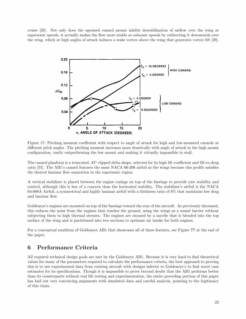
cruise [28]. Not only does the upraised canard mount inhibit destabilization of airflow over the wing atsupersonic speeds, it actually makes the flow more stable at subsonic speeds by redirecting it downwards overthe wing, which at high angles of attack induces a wake vortex above the wing that generates vortex lift [29].
Figure 17: Pitching moment coefficient with respect to angle of attack for high and low-mounted canards atdifferent pitch angles. The pitching moment increases more drastically with angle of attack in the high mountconfiguration, vastly outperforming the low mount and making it virtually impossible to stall.
The canard planform is a truncated, 45o clipped delta shape, selected for its high lift coefficient and lift-to-dragratio [55]. The AB1’s canard features the same NACA 66-206 airfoil as the wings because this profile satisfiesthe desired laminar flow separation in the supersonic region.
A vertical stabilizer is placed between the engine casings on top of the fuselage to provide yaw stability andcontrol, although this is less of a concern than the horizontal stability. The stabilizer’s airfoil is the NACA64-008A Airfoil, a symmetrical and highly laminar airfoil with a thickness ratio of 8% that maintains low dragand laminar flow.
Goldeneye’s engines are mounted on top of the fuselage toward the rear of the aircraft. As previously discussed,this reduces the noise from the engines that reaches the ground, using the wings as a sound barrier withoutsubjecting them to high thermal stresses. The engines are encased by a nacelle that is blended into the topsurface of the wing and is partitioned into two sections to optimize air intake for both engines.
For a conceptual rendition of Goldeneye AB1 that showcases all of these features, see Figure ?? at the end ofthe paper.
6 Performance Criteria
All required technical design goals are met by the Goldeneye AB1. Because it is very hard to find theoreticalvalues for many of the parameters required to calculate the performance criteria, the best approach to provingthis is to use experimental data from existing aircraft with designs inferior to Goldeneye’s to find worst caseestimates for its specifications. Though it is impossible to prove beyond doubt that the AB1 performs betterthan its counterparts without real life testing and experimentation, the entire preceding portion of this paperhas laid out very convincing arguments with simulated data and careful analysis, pointing to the legitimacyof this claim.
22
To find an upper bound for the thrust specific fuel consumption (TSFC) of its engines, the Concorde’sefficiency at supersonic cruise should be appropriately scaled. The efficiency of its Olympus engines varieslinearly with velocity [22], and at Mach 2.2, they boast an TSFC of 1.195. Goldeneye’s average supersoniccruise velocity of Mach 1.7 is 22.7% lower than the Concorde’s, so scaling the TSFC value by the same amountGoldeneye’s TSFC is calculated to be 0.923. While this value is lower than most subsonic business jets, notethat it is nearly impossible to achieve comparable TSFC values as a supersonic aircraft, and that this estimateis merely a baseline efficiency that does not even account for the performance improvements of the variablegeometry inlet.
Given this value, a lower bound for Goldeneye’s range can be estimated by the Bregeut Range Equation [25]:
Range =v · CL
CD
g · TSFC· ln(Winitial
Wfinal
)where v is the plane’s velocity, g is the acceleration due to gravity, Winitial is the initial weight of the aircraft,and Wfinal is its final weight. A Winitial/Wfinal value of 1.5 implies that Goldeneye carries half as much of its dryweight in fuel, a reasonable that is true of many business jets currently in service, including the GulfstreamG280 [24], previously used for a mass estimate of the AB1. In fact, because it is a supersonic airliner, ifanything Goldeneye would probably have a higher actual Winitial/Wfinal than subsonic business jets, whichwould increase its range. In any case, a lower bound for Goldeneye’s range is calculated to be 4227 nauticalmiles.
Obviously, the AB1 meets the cruise speed target of Mach 1.6–1.8 and the payload of 12 passenger since itwas designed from the ground up to meet these parameters. With a TSFC of 0.923 and engines capable ofsupplying 4883.29 lbf (21722N) of thrust, Goldeneye can cover its maximum range in just 3.96 hours at Mach1.6 (1066.78 knots). This flight requires 17853 pounds of fuel, so Goldeneye’s fuel efficiency comes out to 2.84passenger-miles per pound of fuel, far exceeding the design requirement of 1.00 at cruise conditions. Underthose circumstances, the AB1 consumes merely 35.2% of the amount of fuel that could be consumed whilestill meeting the fuel efficiency goal.
For the sake of calculation, Goldeneye’s takeoff field length can be divided into two segments: takeoff groundroll and horizontal range required to climb to an altitude of 35 feet, satisfying the Federal Aviation Adminis-tration’s takeoff minimum. The former is defined as follows:
dTO =mTO · (vLO − vW )2
2 · (FTO −DTO − µ · (mTO · g − LTO)−mTO · g · sin γ)
d ≡ Distance v ≡ Velocity = 155kts m ≡ Mass = 17962kgF ≡ Thrust = 40000N (Cruise + 18278N) D ≡ Drag = 29410kN µ ≡ Coefficient of Friction = 0.71L ≡ Lift = 480kN γ ≡ Runway Slope = 0◦ Subscript TO ≡ TakeoffvW = Wind Speed
As a preliminary calculation, the runway is taken to be perfectly flat and the wind to be 0 knots, which yieldsa takeoff ground roll of 1138.07 meters, or 3373.83 feet. To use the remaining 3626.17ft of runway left to clearthe takeoff screen, Goldeneye must climb at an minimum angle of 0.55◦. A climb angle of 10◦ comfortablyclears the end of the runway by a vertical distance of 639.39 feet, and a maximum climb angle of 15◦ gives971.63 feet of vertical clearance.
23
7 Conclusion
The feasibility of developing Goldeneye comes down to design challenges, developmental roadblocks, andeconomics. Goldeneye’s propulsion is an offshoot of a tried and true engine. Many of the most dauntingengineering challenges with which engine production would normally be faced have already been addressed bydecades of research and development leading up to the Concorde’s release. Goldeneye need only incorporateexisting technology to build its propulsion system, which directly reduces R & D costs. More importantly,these improvements bolster the AB1’s fuel efficiency, which would reduce prices and make the plane morecommercially viable. This is especially important considering that business jets are normally a luxury thatmost people cannot afford, marketed exclusively to the wealthy. By making high-end supersonic air travel myaffordable, Goldeneye could reach more customers than its competitors and tap further into the market, whichwould increase competition and improve the industry as a whole. If eye-catching enough, the modification ofthe Olympus 610 engine could hopefully be undertaken in conjunction with Rolls-Royce, the engine’s originalmanufacturer, whose collaboration would significantly aid Goldeneye’s team both financially and scientificallyby providing funding, support, and a swath of knowledge about the engine it spent so long developing.
The most significant implementation challenge of the AB1 is its retractable wing panel. The wing’s hollowinternal structure is heavily loaded by the panel and its tracks, which may be subject to jams and actuationmalfunction. To address this issue, regular inspection and maintenance of the mechanism above and beyondthe already stringent regulations and safety requirements to which aircraft are held would be essential tominimize the risk of mechanical failure. From a material cost standpoint, the use of components such astitanium spars and fasteners may drive up fabrication costs. However, recent manufacturing advancementsmay facilitate ease of production for some required components. Selective Laser Sintering (SLS) could beused to rapidly prototype and test the system. This process consists of scanning a laser over metal particlesat specific points in space to form the desired three-dimensional part, enabling swift integration and costreduction [? ].
With this in mind, Goldeneye would seek to take advantage of existing aerospace alloys and other commonlyused materials. Consequently, its manufacturing facilities would not require extensive modification or retoolingoutside of some very specific modern manufacturing processes necessary for the production of complex parts.Many of the metals most heavily used in Goldeneye’s design are readily available and relatively cheap. Thefuselage’s Ti-6Al-4V alloy is used extensively outside of the aerospace industry in chemical and biomechanicalapplications. Its ubiquity serves to reduce costs at every stage of production from bulk material purchasingto manufacturing. Similarly, 7075 aluminum, found in the wing spars and ribs, and 6061 aluminum, foundin the engine intake fan and other internal elements, have long, distinguished histories of involvement inaircraft construction. Their relatively low cost and high reliability make them very well suited for Goldeneye’sproduction. Inconel 792, used in the turbine fan, is a sand-castable alloy, produced by a method that allowsfor the fabrication of complex part geometries in a much more affordable manner than comparable processes.Ti-5553, present in the engine combustion chamber, is also easily castable. By purchasing common, high-quality materials in bulk and taking advantage of efficient and advanced manufacturing processes, the priceto build and fly the AB1 would be significantly reduced.
Goldeneye’s greatest strength would perhaps lie in its innovative features and marketable appeal. People willalways want a part of the latest technology, regardless of the industry. This is readily obvious by observing howso many companies try to market and sell their products, from iPhones to Teslas and everything in between.Goldeneye is by definition already on the cutting edge of the aerospace industry simply by being bold enoughto spearhead the effort to reintroduce commercial supersonic aviation to the world. But more than that, theAB1’s technological innovations could make it relevant for decades to come. True variable wing geometryhas never before been attempted by a commercial plane, and certainly not in the way Goldeneye’s radialmechanism works. On top of being exciting , sexy, and highly advertisable, this keystone of the AB1 designcould genuinely have the ability to revolutionize not just commercial air travel, but the aerospace industry asa whole, from private companies to the armed forces. This combination of practicality, versatility, and allureis what ensures Goldeneye’s prolonged success.
24
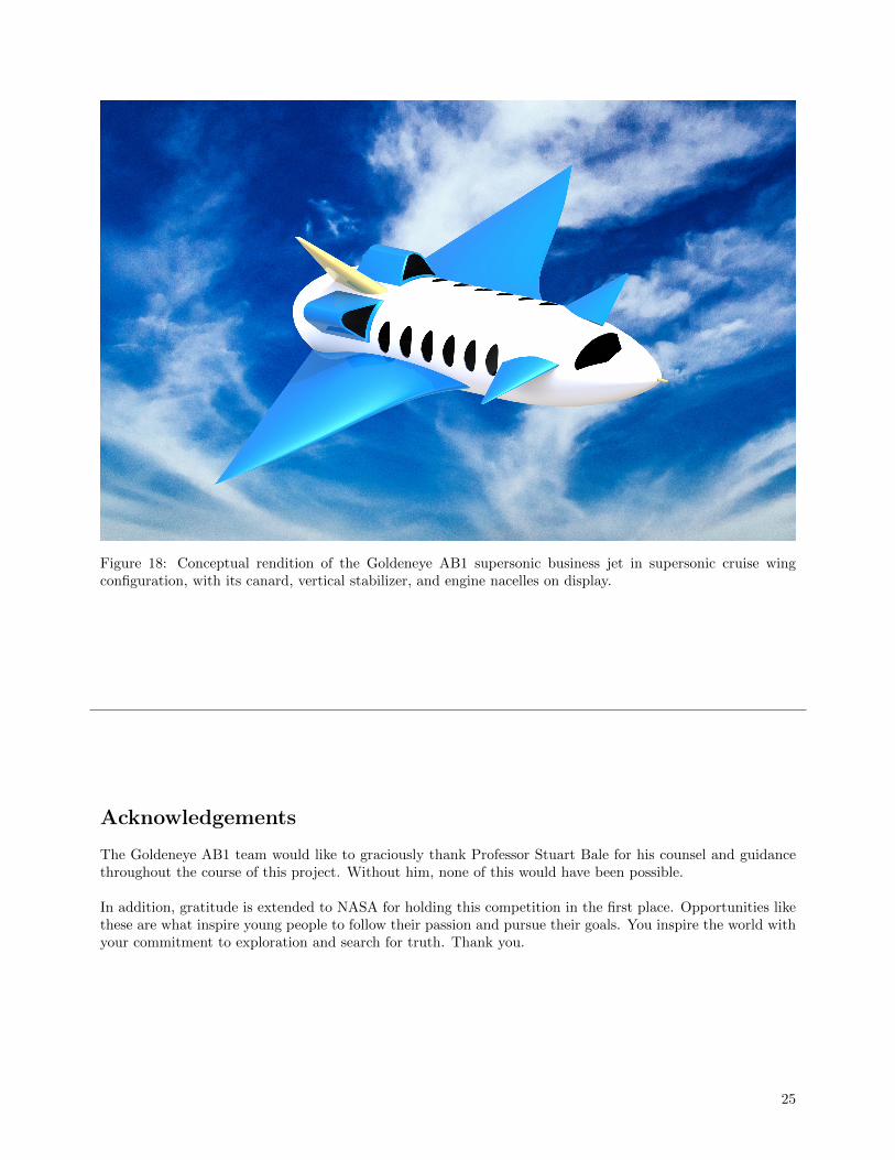
Figure 18: Conceptual rendition of the Goldeneye AB1 supersonic business jet in supersonic cruise wingconfiguration, with its canard, vertical stabilizer, and engine nacelles on display.
Acknowledgements
The Goldeneye AB1 team would like to graciously thank Professor Stuart Bale for his counsel and guidancethroughout the course of this project. Without him, none of this would have been possible.
In addition, gratitude is extended to NASA for holding this competition in the first place. Opportunities likethese are what inspire young people to follow their passion and pursue their goals. You inspire the world withyour commitment to exploration and search for truth. Thank you.
25
References
[1] Kumar, M., Kannan, M., Kumar, V., Manigandan, A., Praveen, G. ”Analysis of Shock over NACA 66-206 at Supersonic Regime”. Advances in Aerospace Science and Applications, Vol. 3, No. 2, pp. 125-130,Hindustan University, Padur, India, 2013.https://www.ripublication.com/aasa/aasav3n2spl_16.pdf
[2] Wang, F., Milanovic, I., Zaman, K., Povinelli, L. ”A Quantitative Comparison of Delta Wing Vortices inthe Near-Wake For Incompressible and Supersonic Free Streams”. J. Fluids Eng 127(6), 1071-1084, July12, 2005.http://fluidsengineering.asmedigitalcollection.asme.org/article.aspx?articleid=1430232
[3] Kroo,I: “Unconventional Configurations for Efficient Supersonic Flight.” Stanford University June 6, 2005.Page 13.http://aero.stanford.edu/reports/vki kroo supersonics.pdf
[4] Sadraey, Mohammad: “Aircraft Design: A Systems Engineering Approach.” Chapter 5. Wiley, 2012. Page176.http://www.academia.edu/4573651/Wing Design i Chapter 5 Wing Design Mohammad Sadraey
[5] Sadraey, Mohammad: “Aircraft Design: A Systems Engineering Approach.” Chapter 5. Wiley, 2012. Page235,239.http://www.academia.edu/4573651/Wing Design i Chapter 5 Wing Design Mohammad Sadraey
[6] Sadraey, Mohammad: “Aircraft Design: A Systems Engineering Approach.” Chapter 5. Wiley, 2012. Page205http://www.academia.edu/4573651/Wing Design i Chapter 5 Wing Design Mohammad Sadraey
[7] Sadraey, Mohammad: “Aircraft Design: A Systems Engineering Approach.” Chapter 5. Wiley, 2012. Page224http://www.academia.edu/4573651/Wing Design i Chapter 5 Wing Design Mohammad Sadraey
[8] Mason, W.H.: “Supersonic Aerodynamics.” Virginia Tech. 7/31/2016. Chapter 10, page 20.http://www.dept.aoe.vt.edu/ mason/Mason f/ConfigAeroSupersonicNotes.pdf
[9] Mohan Kumar G, Manoj Kannan G, Vignesh Kumar R, Manigandan A, and Praveen G: “Analysis ofShock over NACA 66-206 at Supersonic Regime.” Advances in Aerospace Science and Applications. ISSN2277-3223 Volume 3, Number 2 (2013), pp. 125-130https://www.ripublication.com/aasa/aasav3n2spl 16.pdf
[10] Jones, Robert T: “Report 1284: Theory of Wing-Body drag at Supersonic Speeds.” NACA Cranfield,United Kingdom. 1956.http://naca.central.cranfield.ac.uk/reports/1956/naca-report-1284.pdf
[11] Sadraey, Mohammad: “Aircraft Design: A Systems Engineering Approach.” Chapter 5. Wiley, 2012. Page223.http://www.academia.edu/4573651/Wing Design i Chapter 5 Wing Design Mohammad Sadraey
[12] ConcordeSST.com: “Concorde Technical Specs: Fuel system.”http://www.concordesst.com/fuelsys.html
[13] Hall, Nancy: “Center of Pressure.” NASA, Glenn Research Center.https://www.grc.nasa.gov/WWW/k-12/airplane/cp.html
[14] Cornei, Simona: “Mach number, relative thickness, sweep and lift coefficient of the wing - An empiricalinvestigation of parameters and equations.” Department of Automotive and Aeronautical Engineering,Hamburg University of Applied Sciences. 31/05/2005.http://www.fzt.haw-hamburg.de/pers/Scholz/arbeiten/TextCiornei.pdf
i
[15] NACA 66-206http://airfoiltools.com/airfoil/details?airfoil=naca66206-il
[16] Araujo, G., Almeida, S.”Design Procedure for a Fowler Flap Mechanism”. 18th International Congressof Mechanical Engineering, Ouro Preto, Brazil, November 2005.http://www.abcm.org.br/anais/cobem/2005/PDF/COBEM2005-0040.pdf
[17] Grumman F-14 Tomcathttps://en.wikipedia.org/wiki/Grumman F-14 Tomcat#Variable-geometry wings and aerodynamic design
[18] Concorde Elevons and Ruddershttp://www.heritageconcorde.com/concorde-elevons-and-rudder
[19] Interference Drag of Wing MountsSadraey, M. H., Wing Design, in ”Aircraft Design: A Systems Engineering Approach”, John Wiley &Sons, Ltd., Chichester, UK, 2012, pp. 12
[20] Sears-Haack BodyAshley, H., Landahl, M., ”Aerodynamics of Wings and Bodies”, Addison-Wesley, 1965.
[21] Airplane Aerodynamics and Performance, Roskam Jan and Lan C E
[22] Propulsion and Efficiency, SMU Lyle School of Engineeringhttp://lyle.smu.edu/propulsion/Pages/efficiency.htm
[23] Aircraft Performance, MIT OCWocw.mit.edu/ans7870/16/16.unified/propulsionS04/UnifiedPropulsion4/UnifiedPropulsion4.htm
[24] Gulfstream G280 Specificationsgulfstream.com/aircraft/gulfstream-g280
[25] Bregeut Range Notes, Fall 2008, MITweb.mit.edu/16.unified/www/FALL/Unified Concepts/Breguet-Range-U2-notes-Fall08(2).pdf
[26] Saturn V Launch Simulationsbraeunig.us/apollo/saturnV.htm
[27] Aspects of Aircraft Design and Control, Olivier Cleynen, May 2014documents.ariadacapo.net/cours/aspects aircraft design/lecture 8.pdf
[28] Anderson, Seth B. ”A Look at Handling Qualities of Canard Configurations”. NASA, September 1986.https://ntrs.nasa.gov/archive/nasa/casi.ntrs.nasa.gov/19870013196.pdf
[29] ”Jet Aircraft – Effect of a close-coupled canard on a swept wing”. SAI Research Report (Abstract). SageAction, 2009.http://www.sageaction.com/aircraft testing1.htm#JetAircraft
[30] Onyszko, A., and Kubiak K., ”Method for Production of Single Crystal Superalloys Turbine Blades”,Archives of Metallurgy and Materials, Vol. 54, No. 3, 2009, pp. 765-771.
[31] Debiasi, M., and Papamonschou, D. ”Cycle Analysis for Queiter Supersonic Turbofan Engines”, Universityof California, Irvine, 2001.
[32] Papamoschou, D., and Debiasi, M., ”Directional Suppression of Noise from a High-Speed Jet”, AIAAJournal, Vol. 39, No. 3, 2001, pp. 380-387.
[33] Sweetman, B., ”YF-22 and YF-23 Advanced Tactical Fighters”, Motorbooks International, 1991, Osceola,WI, pp. 61-64.
[34] Murakami, E., and Papamoschou, D., ”Mixing Layer Characteristics of Coaxial Supersonic Jets”, AIAAJournal, 2000-2060.
ii
[35] Papamoschou, D., ”Mach Wave Elimination from Supersonic Jets” AIAA Journal, Vol.35, No.10, 1997,pp.1604-1611
[36] Papamoschou, D., and Debiasi, M., ”Noise Measurements in Supersonic Jets Treated with the Mach WaveElimination Method”,AIAA Journal, Vol. 37, No. 2, 1999, pp. 154-160.
[37] Debiasi, M., and Papamoschou, D., ”Noise from Imperfectly Expanded Supersonic Coaxial Jets”, AIAAJournal, Vol.39, No.3, 2001, pp.388-395.
[38] Hill, P., and Peterson, C., ”Mechanics and Thermo dynamics of Propulsion”, 2nd Ed., Addison Wesley,1992, New York
[39] Space Flight Systems, Glenn Research Center, Online Educational Material: Corrected Airflow per Area
[40] Cengel, Yunus A., and Boles, Michael A. Thermodynamics: An Engineering Approach. New York, NY:McGraw-Hill, 2011. Print.
[41] Sontag, Borgnakke and Van Wylen. Fundamentals of Thermodynamics. 6th Ed., John Wiley & Sons,Inc., 2003. Print.
[42] Kittel, C., and Kroemer, H. Thermal Physics. 2nd Ed., W.H. Freeman, 1980. Print.
[43] Jackson, P.A. ”Jane’s all the World Aircraft, 1998-1999”, Sentinel House, 1998, Couldson UK.
[44] Roth, B., and Mavris, D., ”Analysis of Advanced Technology Impact on HSCT Engine Cycle”, AIAAPap er No. 99-2379, 1999.
[45] Sanghi, V., and Lakshmanan, B.K., ”Some Trends in Engine Cycle Selection and Overall Aircraft Sizing”,Proceedings of the XIV International Symposium on Air Breathing Engines, ISABE pap er 99-7112, 1999.
[46] Freedman, D., Pisani, R., and Purves, R. ”Statistics”. 4th Ed., W.W. Norton & Company, 2007.
[47] Devore, J. L. ”Probability and Statistics for Engineering and the Sciences”. 8th Ed., Cengage Learning,2011.
[48] American Environment Company, Inc. ”Acoustic Power and Sound Pressure Levels of Typical NoiseSources”. Medford, N.Y., 2017.
[49] ”Inlet Performance”, NASA Glenn Research Center, edited by Nancy Hall, 2015.
[50] Webber, H., Feast, S. and Bond, A. “Heat Exchanger Design in Combined Cycle Engines” IAC-08-C4.5.1,2008.
[51] Mehta, U., Aftosmis, M., Bowles, J., & Pandya, S. ”Skylon Aerodynamics and SABRE Plumes”. 20thAIAA International Space Planes and Hypersonic Systems and Technologies Conference., Glasgow, Scot-land, 2015
[52] Musielak, D. ”SABRE: A high speed air breathing rocket engine fo the SSTO SKYLON spaceplane”.2012.
[53] Varvill, R. and Bond, A. “The Skylon Spaceplane: Progress to Realization”. JBIS, Vol. 61, pp. 412-418,2008.
[54] Aggarwal, R., Lakhara, K., Sharma, P.B., Darang, T., Jain, N., Gangly, S. ”SABRE Engine: Single Stageto Orbit Rocket Engine”.
[55] Lacey, D,. ”Aerodynamic Characteristics of the Close-Coupled Canard as Applied to Low-to-ModerateSwept Wings”. Vol.1, David W. Taylor Naval Ship Research and Development Center, Bethesda, MD,1979.http://www.dtic.mil/dtic/tr/fulltext/u2/a063819.pdf
iii
[56] Rolls-Royce Is Ready For A Supersonic Business Jethttps://airinsight.com/2017/04/10/rolls-royce-ready-supersonic-business-jet/
[57] Liebhardt, B., Lutjens, K. ”An Analysis Of The Market Environment For Supersonic Business Jets”.German Aerospace Center-Air Transportation Systems. Hamburg, Germany, 2011.http://elib.dlr.de/75275/1/DLRK2011 Liebhardt-L%C3%BCtjens.pdf
[58] Supersonic Business Jet Market Expected To Grow 4% Annuallyhttp://aviationweek.com/awin-only/supersonic-business-jet-market-expected-grow-4-annually
[59] Shama Rao, N., Simha, T. G. A., Rao, K. P., Ravi Kumar, G. V. V. ”Carbon Composites Are BecomingCompetitive and Cost Effective”. Infosys.
iv