Embed Size (px)
Citation preview

Golder Associates IrelandTown Centre House,Dublin Road, Naas,Co. Kildare,Ireland
Tel: [353] (0)45 874411Fax: [353] (0)45 874549E-mail: [email protected]://www.golder.com
_____________________________________________________________________________________________________________________________________________________________
OFFICES IN IRELAND, UK, FINLAND, GERMANY, HUNGARY, ITALY, FRANCE, SPAIN, PORTUGAL, SWEDEN, CANADA, USA, PERU, CHILE, BRAZIL,AUSTRALIA, NEW ZEALAND, INDONESIA, HONG KONG, THAILAND
Company Registered in Ireland No 297875. At Trident House, Dublin Road, Naas, Co. Kildare, Ireland
Prepared by Golder Associates
on behalf of
North Tipperary County Council
Civic Offices
Nenagh
County Tipperary
June 2007 06715300.01
30 Copies – North Tipperary County Council
4 Copies – Golder Associates Ireland
REHABILITATION PLAN FOR THE GORTMORE TMF
SILVERMINES
CO. TIPPERARY

REPORT ISSUE FORM
Version B.0Issue
Date27 June 2007
Document
Title
Rehabilitation Plan for the Gortmore TMF
Silvermines Co. Tipperary
06715300.01
List of Authors Staff of:
Golder Associates Ireland
Golder Associates (U.K.) Ltd.
Golder Associates Inc.
Consultnet Ltd.
Client North Tipperary County Council
Client Reference
Project Manager
Approval
Barry Balding(signature)
Reviewer David Barry
Bill Dallas
Geoff Parker
Roger White(signature)
Report Name No. Copies
Distribution North Tipperary County Council
Golder Associates
30
4
Definition of Version Code:
D. Applied during initial drafting of the report before it has been reviewed.
C. Applied after the report has been reviewed but before it has been approved by theProject Manager.
B. Applied after the Project Manager has approved the report ready for issue to the client.
A. Applied to reports after external/client review.
The version number starts at ‘0’ and is raised by ‘1’ at each re-type.
June 2007 ES - 1 06715300.01
B.0
Golder Associates
EXECUTIVE SUMMARY
Introduction
The Conceptual Design for the remediation of the Gortmore Tailings Management Facility
(TMF) was published in November 2005 (SRK Phase IV Report) following various
investigations of mine sites in the Silvermines area.
Rehabilitation of the TMF has been a significant concern for various stakeholders. The key
objective identified during the conceptual design process was to ensure stability of a self
sustaining vegetation cover to prevent dust blowing from the top surface and the edges of the
TMF, as large areas of the surface have poor or no vegetation. Significant areas of the TMF
have a good cover of vegetation which are currently self sustaining.
The Government (Department of Communications, Marine and Natural Resources) has
agreed that the state will assume responsibility for the Silvermines Rehabilitation Project,
with site work administered and carried out on behalf of North Tipperary County Council.
Following a public tendering process, Golder Associates Ireland (Golder) was appointed in
June 2006, as Consultants to North Tipperary County Council, to undertake the detailed
engineering design for the project including necessary additional site investigations,
preparation of environmental documents required for the licensing/permitting processes,
preparation of contract drawings and documents, and ultimately overseeing construction of
the works, including handover and certifying the completion of the works to specification.
The Conceptual Design prepared was accepted by all stakeholders, including
DCMNR, NTCC, IAG, EPA and local residents, as being appropriate to the effective control
and mitigation of environmental impacts of the site on the local environment. Golder adopted
the essential conclusions of the Conceptual Design as the basis of their TMF rehabilitation
design.
Thus, a pragmatic approach has been taken in dealing with the adaptation of the Conceptual
Design, to produce an optimum solution taking into account the best available techniques not
entailing excessive costs for Gortmore, based on its unique site specific conditions.
This report summarises information on the engineering design of the TMF including
significant new environmental information resulting from the investigations undertaken to
facilitate the design process. This document also provides supporting technical
documentation to accompany the drawings submitted for regulatory approval under Part VIII
of the Planning and Development Act 2000.
The rehabilitation proposed at Gortmore essentially involves the establishment of a self-
sustaining cover on the TMF, improvement of existing surface water, groundwater and stream

June 2007 ES - 2 06715300.01
B.0
Golder Associates
sediment quality, landscaping and ancillary engineering works related to the TMF decanting
system, wetlands and Settlement Ponds.
Hydrogeological and Geotechnical Investigations
Supplementary ground investigations were carried out (October and November 2006),
involving the drilling of boreholes through the tailings surface. Standpipe-piezometer
monitoring wells were installed and sealed at two different depths near the edge of the outer
dam wall. Additional boreholes were drilled close to the toe of the dam wall through
overburden into bedrock. In some cases made ground was found overlying the overburden.
In summary, the findings of the supplementary site investigations indicate that the tailings
range in thickness from 8m to 10m. The TMF overlies native overburden comprising mainly
alluvium and glacial till. Sand/Gravel deposits were also encountered underlying the
alluvium and glacial till at depth in a number of the boreholes. The native overburden that
was encountered in the perimeter boreholes was found to range in thickness between 2.2m
and 8.7m. The native overburden is underlain by limestone of the Ballysteen Formation. The
boreholes drilled near the toe of the dam were all terminated between 15m and 16m within the
limestone bedrock.
The boreholes and site observations have established that within the TMF there is a thin crust
of oxidized tailings overlying very soft grey unoxidized tailings which varies in thickness
from about 100mm in the centre to in excess of 1000mm (1m) at the edges of the TMF. The
grading of the tailings varies from location to location across the TMF as does its strength.
Water levels have been measured frequently in the monitoring boreholes since
November 2006. The water-table within the tailings near the dam wall is estimated to be
between 1m and 2m below the tailings surface which is also reflected by the presence of a
permanent water-body (Tailings Pool) close to the centre of the TMF. Water level readings in
the monitoring borehole pairs, that were sealed deep and shallow in the tailings, indicate
downward vertical gradients and hence downward seepage within and along the dam walls of
the TMF.
The downward seepage in the tailings around the edge of the TMF is seen as ‘seeps’ at the
external toe of the dam. In the boreholes drilled at the toe of the dam wall there is evidence of
little to no downward hydraulic gradient between the overburden and underlying bedrock.
Information from the boreholes around the toe of the dam also shows a slight horizontal
hydraulic gradient from northeast to southwest in the upper 15m of the underlying bedrock.
Having reviewed the previous geotechnical investigations carried out around the TMF and
taken into account observed conditions in the most recent boreholes (2006), the slopes are
presently stable. However, Golder consider for long term dam stability (requiring some

June 2007 ES - 3 06715300.01
B.0
Golder Associates
degree of maintenance), the slope gradient should not be steeper than 1V:1.5H. To ensure
long-term stability buttressing of the embankment slopes is proposed (in certain locations) .
Tailings and Vegetation Assessment
Investigations undertaken as part of the detailed design process on the existing vegetation,
including the associated tailings geochemistry, found that areas of bare tailings were
characterised by low pH, high EC, high sulphate and high heavy metal content. Vegetation
samples from poor grassland areas showed elevated concentrations of sulphate, lead, zinc,
cadmium, manganese and zinc and in some cases these were above recommended toxicity
levels. Samples of tailings taken from the bare and poor grassland areas indicated the
potential for acid generation. It appears that upward movement of acidity and potentially
phytotoxic metal and sulphate salts has severely impacted on vegetation sustainability in the
poor grassland areas.
It is proposed, based on the results of the analysis undertaken, that rehabilitation work already
proposed for the bare tailings areas be extended to the poor grassland areas based on
vegetation toxicity levels and associated acid generating potential of the tailings underlying
these areas.
The existing good grassland consists of primarily two dominant grass genus, Agrostis and
Festuca, which have low nutrient demand and are self-sustaining.
It is recommended that the areas of good grassland and gorse be subject to performance
monitoring on a bi-annual basis (twice yearly), post rehabilitation of the TMF.
Surface Water and Groundwater Quality
Investigations were undertaken on surface water, groundwater and steam sediments as part of
the detailed design process. The site assessments undertaken as part of the initial
investigations did not indicate any significant surface water and groundwater issues in the
local environment.
The volunteer wetlands around the perimeter of the TMF are removing suspended solids and
metals from the surface water and seepages emanating from the TMF. There are however
numerous uncontrolled seepages direct to the river from the volunteer wetlands. These
seepages will be channelled into the refurbished wetlands via a series of perimeter toe drains
as part of the proposed site remediation. The Settlement Ponds to the east of the tailings pond
are not functioning effectively and will be refurbished to provide additional wetland capacity
to aid the long term management of the water quality from the TMF. Discharge of waters
from the wetlands will be in a controlled manner into the Kilmastulla River. The TMF is not
adding significantly to the metal loading in the KIlmastulla River, at Cranna Bridge, further
June 2007 ES - 4 06715300.01
B.0
Golder Associates
downstream of the TMF, metal concentrations in the River were found to be within the range
of the relevant standards. Biological water quality monitoring in the adjacent
Kilmastulla River indicated no significant change in recent years with a Q rating of 3-4.
All surface water samples at Gortmore were initially assessed in terms of the EC Quality of
Salmonid Waters Regulations (S.I. 293 of 1988) and the EC Quality of Surface Water
Intended for Abstraction of Drinking Water Regulations (S.I. 294 of 1989) (A1 level). These
are the standards that have been used as the basis for treated water discharge limits in the
IPC Licences at The Lisheen Mine and Galmoy Mine with some exceptions as regards
Fe and Mn. They are also similar to the EPA BATNEEC Guidance Note for the Extraction of
Minerals (1997). In addition, these standards are referenced in the Silvermines Expert Group
Report (EPA 2004). The ideal for an abandoned mine site(s) such as Silvermines would be to
achieve such water quality standards as far as reasonably practicable, given the site’s history
and the unique naturally occurring mineralogical conditions of the area. The standards will be
used herein as the target for compliance and modified where prudent and acceptable. The aim
will be to progress towards attainment. Where limits are imposed in both regulations, the
Salmonid Limit will be applied as it is considered more relevant, as no surface water
abstraction points are known on the Kilmastulla River down stream of Gortmore.
Results from groundwater analysis for samples taken from recently drilled holes (2006) and
from previously drilled holes (2001) show similar values for metals and sulphate
concentrations. This is not unexpected as the boreholes were drilled on the tailings dam
surface (2006 only) and close to the toe of the dam wall (2001 & 2006). Previous studies of
groundwater undertaken in the Silvermines area have found no evidence of groundwater
contamination at any potential receptor.
Metals were found in river sediments alongside the TMF, these are most likely as a result on
the numerous uncontrolled seeps and drains which can wash sediment into the river
particularly during periods of high rainfall. The proposed improvements to the perimeter
wetlands will significantly reduce the sediment loading on the adjacent river.
The proposed remediation works on the TMF site is expected to improve the existing surface
water, groundwater and stream sediment loading quality. The upgrading of the wetlands and
TMF drainage systems will provide for increased capture and treatment of leachate generated.
It is recommended that long-term monitoring be incorporated into the design for the TMF to
monitor for any potential surface water and groundwater contamination from the TMF site.
Proposed Capping System
A pragmatic approach has been taken in dealing with the adaptation of the SRK’s Conceptual
Design to produce an optimum design solution for Gortmore, based on an increase in the area

June 2007 ES - 5 06715300.01
B.0
Golder Associates
to be capped, a detailed evaluation of rehabilitation options relevant to Gortmore’s conditions,
with mitigation measures targeted at risk reduction.
The principal elements of the recommended capping design (from the bottom up) are as
follows:
Geosynthetic layer;
300mm layer (average) of granular non-acid generating crushed stone (rockfill);
Geosynthetic layer; and
200mm layer (minimum) of growth medium, together with a suitable seeding mixture
The granular rockfill layer will act as a capillary break layer, and the 300mm thickness is to
facilitate drainage and minimise risks of ponding on the surface which could ultimately
compromise the growth-medium and vegetative layer. Further, it is Golder’s experience that
300mm is the average thickness that can be placed and spread using appropriate equipment
without disturbing the underlying tailings (or geotextile). Thus, the total thickness of the
capping system is c.500mm.
The proposed self-sustaining capping system comprises a rockfill layer (i.e.capillary break),
300mm thick on average, overlain by a soil layer (i.e. growth-medium), minimum 200mm
thick. Due to the weak nature of the tailings, geosynthetic layers will be incorporated into the
design. In general, the layer of crushed stone will be placed on a geogrid in areas where haul
roads will be constructed to allow placement of the rockfill across the surface and on a non-
woven geotextile, in other areas. The stone and soil layers will be separated by a lighter non-
woven geotextile. The grass seed mix will be approximately 25-35 % A. stolonifera, 30-40 %
F. rubra, 15-25 % L. perenne, 5-10% P. pratense and 3-10 % T. repens. To improve the
chances of seedling establishment, it is proposed that seeding will be at the upper end of
the 150-200 kg/ha rate for revegetation of mine wastes.
The identified total area for capping of the TMF surface is about 24.5ha. This area comprises
(i) bare tailings and poor grassland that is not considered self-sustaining and (ii) a narrow
taper from the 500mm thick cap to the good grassland. Treatment of the embankment slopes
will also be carried out to cover potentially acid generating materials and/or buttress the
slopes. Rockfill will be used on the embankment slopes requiring treatment. The time
available to place the cap is dictated by the surface conditions on top of the tailings.
In detail there are three types of capping:
Type I Cap
This capping type will be used over large areas of the TMF. It will include geosynthetic
layers, a rockfill capillary break layer, 300mm thick on average and growth medium layer
minimum 200mm thick. Golder has identified a total area for Type I capping on the surface of

June 2007 ES - 6 06715300.01
B.0
Golder Associates
the TMF of about 20.5 ha. This includes bare tailings, poor grassland and a narrow transition
zone from those areas onto the good grassland.
The capping layers on these areas will be tapered or feathered out across the existing
uncapped surface over a distance of about 2 to 4m from the edges. In some areas the existing
gorse will need to be removed to allow access and/or placement of the cap. The extent of
gorse removal will be kept to a minimum. On upslope edges of the cap, where it tapers out on
the existing good areas of grassland, either a French contour drain will be constructed or the
rockfill layer will be left exposed to allow drainage throughout.
Type II Cap
This type of capping will be placed along the edges of the TMF where the oxidised tailings
crust has been measured between 1 and 1.6m thick (from borehole information). It is
envisaged that due to the depth of the watertable along the edges of the TMF that a capillary
break will not be required. Instead a 300mm thick layer of growth medium will be placed on
a geosynthetic separator layer and the reshaped slopes.
Any surplus excavated tailings will be placed at the toe of the cut slopes and/or spread along
the edges of the TMF in areas to be capped. There is no intent to spread the cutting on good
grassland. Where the ‘upper lift’ has grass that appears to sustainable this will not be
disturbed. However, in areas requiring capping and where there is gorse, the gorse will be
removed only to the extent required to place the capping materials. The edge capping will
necessarily be feathered or tapered out on to good areas of grassland. It is envisaged that
there will be c. 2.5ha of Type II capping over selected areas of the outer slopes.
Type III Cap
Selective surface treatment of the lower slopes of the dam walls will be by the emplacement
of crushed rockfill on a layer of geotextile against the embankment. An excavator will place
the rockfill from the top and/or bottom of the embankment depending on access constraints.
This rehabilitation work will be chiefly carried out along the north-eastern and south-western
faces of the dam wall where oxidizing tailings occur. Slopes steeper than 1V:1.5H will be
buttressed to provide
It is envisaged that there will be c. 1.5ha of Type III capping over selected areas of the lower
slopes will be required to provide for long term stability of the slopes.

June 2007 ES - 7 06715300.01
B.0
Golder Associates
Additional Rehabilitation Works
Surface Water Controls
The Tailings Pool on the surface of the TMF will be maintained to ensure at least a specific
minimum size by improving the decant overflow system. At present the water flows from the
pool along an open ditch and into the decant pond via a single pipe. The decant pond
discharges over a rectangular weir into the decant tower, from the bottom of which runs a
500mm diameter concrete pipe (currently broken in several places), which in turn discharges
into the Settlement Ponds at the foot of the dam wall on the north-eastern side.
During the wet winter months an additional pond develops on the surface of the TMF
approximately 100m south of the decant pond. This also drains into the decant pond through
a cutting in the side of the decant pond rock-wall.
The existing drainage channel from the Tailings Pool to the decant pond will be deepened
and lined to provide improved long-term management and control of the seasonally
fluctuating water level in the tailings pool. The capillary rock layer of the new capping will
allow surface water to drain directly into this channel from the newly rehabilitated areas to the
north-west.
The present decant tower is a cast in-situ concrete structure containing ad hoc steel
reinforcement. The structure will be refurbished with new weir boards and fitted with a new
cap, safety grill and access walkway. The existing decant sump will be replaced and
enhanced to handle the flows from the decant tower.
Wetlands Management
Existing wetlands will be refurbished, with uncontrolled seepages form the TMF perimeter
wetlands emanating on the north-eastern side of the TMF, adjacent to the Kilmastulla River
being sealed. The water levels in the existing Settlement Ponds will be lowered and
earthworks will be carried out to modify these ponds to provide additional wetland capacity.
A new concrete outlet structure will be built to prevent erosion between the outfall of the
concrete flume and the Kilmastulla River.
In the south-east of the site (close to the confluence of the Burgess and Kilmastulla Rivers),
drainage from the north-west will be collected in a newly constructed wetland. A perimeter
open toe drain will be constructed inside the existing haul road to collect ‘seeps’ from that
side. This toe drain will be sloped to allow flow into the refurbished wetlands.

June 2007 ES - 8 06715300.01
B.0
Golder Associates
A small pond near the old tailings discharge pipeline ramp will be drained slowly into a
nearby existing wetland and subsequently back-filled with rock. This reinstated area will then
be top-soiled and seeded
Remediation Phase Impact and Mitigation
Climate Change
The potential impact on climate with the rehabilitation of the TMF has been assessed in terms
of greenhouses gases emitted during construction and long term impact of climate change on
the rehabilitated facility. The assessment has included impact of construction traffic
alterations to carbon dioxide emissions. The results indicate that construction traffic during
the rehabilitation phase will have a negligible impact on greenhouse gas emissions. The
potential impact of climate change on the facility has been assessed and considered in the
detailed design criteria for wetlands and vegetative cover layers.
Air
The main potential impact during the construction phase will be due to airborne dust and
potential dust deposition outside the site boundaries. However, any such activities will be
transient in nature.
Dust generated due to capping activities could result from trafficking on the tailings surface,
particularly in prolonged dry conditions. Best practicable means to minimise site dust
emissions will be employed during the rehabilitation phase such as:
Wheel wash for vehicles leaving site;
Water suppression when necessary, to reduce dust emissions;
A road cleaning service to be employed at critical times;
Any stockpiles will be located away from sensitive receptors and the height, sizes and
durations for any stockpiles and tipping operations will be minimised;
Haul routes selected away from sensitive areas where possible;
Regular and ongoing site inspections to identify significant dust sources;
Speed limits on the tailings surface to minimise dust generation;
A complaints procedure will be implemented by the contractor and a project liaison
officer appointed for the site;
The implementation of good site dust minimisation management practices to prevent re-
suspension of exposed tailings will reduce the impact upon sensitive receptors. If these
preventative measures are used effectively, the potential dust impact of the scheme is not
considered significant. Air quality in the area around the TMF will improve significantly post
remediation due to a sharp decrease in fugitive dust emission once rehabilitation is complete.

June 2007 ES - 9 06715300.01
B.0
Golder Associates
Noise
Any potentially significant noise emissions associated with the proposed remediation works at
the TMF will be during the capping phase of the works, involving the haulage of capping
materials and placement on the TMF surface.
The highest noise levels are likely to be generated during transportation and placement of
capping materials. One hour average construction noise levels on busy construction sites are
typically less than 65 dB(A) at a distance of 50 m. This includes noise from excavations,
construction plant and vehicles on site. Given the scale of this development construction
noise levels are expected to be lower. Construction noise at any given noise sensitive location
will be variable throughout the construction depending on the distance from the main
construction activity to the receptors.
The average construction noise contribution at the nearest occupied residences in the vicinity
of the northwest corner of the TMF are expected to be 65 dB(A) or lower. While construction
noise may be audible it is unlikely to be intrusive at these properties with no significant
impact. A level of 70dB(A), is considered acceptable for construction works during daylight
hours. Any impact due to construction noise will be transient in nature. Proposed mitigation
measures include:
Working hours will be 07.00 – 20.00 hrs except where emergency works need to be
carried out;
Work will not normally occur on Sundays or Bank Holidays;
Construction plant will be required to comply with S.I. 320 of 1998, Permissible
Noise Levels Regulations and also taking account of BS 5228 - Noise Control on
Construction and Open Sites;
A site representative will be appointed for matters relating to noise and vibration;
All site access roads will be regularly maintained so to minimise vibration and noise
from heavy truck movements.
Such measures will adequately mitigate the impact due to construction noise at the proposed
site. There are no significant noise emissions envisaged post construction, hence no additional
mitigation measures are proposed.
Soils and Geology
The importation of crushed stone/rockfill and ‘growth-medium’ (e.g. topsoil and/or river
dredgings) are a significant impact and cannot be mitigated against as they form part of the

June 2007 ES - 10 06715300.01
B.0
Golder Associates
overall remediation and rehabilitation solution to the Gortmore site as set out in the overall
Silvermines Rehabilitation Plan as agreed between DCMNR, NTCC, interested stakeholders
and the local community.
Regarding operational activities at the Site, the following mitigation measures are proposed:
All refuelling of mobile plant will be undertaken in a temporary hardstanding area
connected to an interceptor. These practices will have little or no effect on drift or
bedrock material;
Mobile plant will be regularly maintained and where plant is damaged or leaking, this
will be dealt with as part of the ongoing operational management of the site; and
Growth-medium (eg. topsoil) will be stored separately, and will be stored in
prescribed thicknesses to ensure best practicable maintenance of soil structure and
fertility for use during final restoration.
In the long-term, there will be no deleterious effects on the soils, overburden or bedrock
caused by the remediation and rehabilitation activities carried out on the site.
Water
The proposed works, which will involve capping the existing exposed areas on the tailings
surface and modifications to the drainage and wetlands are expected to significantly improve
surface water quality in the vicinity of the TMF.
Best practicable means to minimise any potential water quality impacts will be employed
during the construction phase. These measures will include:
Sealing of uncontrolled breaches to the Kilmastulla River from the wetlands, minor
improvement works to the volunteer wetlands and bypass any drainage still entering
the Settlement Ponds in the initial construction phase;
Re-engineering works to the toe, TMF surface and toe drain structures (in select
sectors) in the initial phases of the works, to minimise the impact of uncontrolled
seepage; and
Construction of silt traps to minimise any suspended solids generated during the
construction of new drains around the TMF perimeter.
The proposed cap is likely to significantly improve the water quality run-off from the
TMF surface, particularly after extended dry periods where the current surface is exposed to
oxidation for a number of weeks and subsequently ‘flushed’ by heavy rainfall enabling an
June 2007 ES - 11 06715300.01
B.0
Golder Associates
oxidised layer of sediment and its associated load of mobilised heavy metals to enter the
wetlands and, ultimately the surface water system around the TMF. The proposed cap would
also reduce the impact of wind-generated erosion, (i.e. minimise dust blow from the site).
The improved drainage and wetland systems will improve discharge water quality and reduce
sediment loading to the river.
It is proposed to conduct regular water quality monitoring for a 12 month period post
rehabilitation works in order to assess any change in water quality.
Flora and Fauna
The main impacts on habitats, flora and fauna will occur due to alteration of habitat as a result
of rehabilitation works on the surface of the TMF, and enhancement of the wetlands around
the base. Positive impacts will occur due to the creation of a new grassland habitat. The loss
of bare mine spoil and poor grassland as a result of capping is of no ecological significance.
Although initially, as the seeded species establish, diversity of grassland herbs will be low
and plants of re-colonising bare ground may be present, it is anticipated that established
grassland will be more species rich than the existing habitats in the medium-long term.
Landscaping proposals for screening vegetation will have a positive impact on the
area – creating further habitat for flora and fauna and acting as a wildlife corridor linking
existing habitats.
Traffic
During the construction works it is proposed that two entrances to the site be used; (i) from
the north and (ii) from the south. The use of two entrances will allow for vehicle movements
to and from the site to be scheduled and managed in a planned, and coherent way.
Traffic arriving on the northwest corner of the site will have travelled via the N7, the
predicted traffic volumes will not be significant in terms of existing traffic volumes on this
main road. The rural road will have increased traffic volumes, speed restriction will apply
and haulage scheduling will apply to minimise impact. Passing bays will be required along
this route.
The Southern access to the site will have to be ‘splayed-back’ to allow for the required site
lines to be obtained.
The rural road which runs from Shallee Cross to Nenagh will have increased traffic volumes
during the course of the works. It is proposed that speed restriction and/or traffic lights be put
in place to help with traffic movements to and from the site at this entrance.
June 2007 ES - 12 06715300.01
B.0
Golder Associates
The traffic impact associated with construction workers on the site will be negligible, it is
estimated that an average total of 20 full time persons will be employed on the site at any
time.
Once the rehabilitation work is complete, there are no significant traffic movements
associated with the on-going monitoring of the facility.
Mitigation measures proposed during the works include:
Extending the works programme for a longer period ;
Extending the working day to reduce the hourly movements;
Hauling the growth-medium and crushed stone/rockfill to the site via both southern
and northern entrances, (to lessen the impact at a particular point);
Phasing the work so that only part of the area is capped this year i.e. the bare areas
and the remainder next year;
Phasing the work so that the crushed stone/rockfill only is placed this year and topsoil
is placed next year;
A construction management plan including specific routes and entrances will be
included as part of the conditions of contract for the remediation contractor and this
will be agreed with NTCC Roads Engineers in advance of haulage commencing;
Wheel wash facilities will be provided on site to ensure that construction debris will
not have an impact on the quality of roads in the surrounding area; and
Parking will be provided on site for both employees and visitors.
Long-Term Monitoring
Upon completion of the rehabilitation works, and as part of the final design solution,
extensive monitoring programmes (including dust, surface water, groundwater, stream
sediments) will be incorporated into the Gortmore TMF Management Manual, which will be
available at project handover stage.
The long-term success of the proposed rehabilitation works will be measured by a
comprehensive on-going environmental monitoring plan. This plan will monitor performance
during the works, in the immediate aftermath and will then be developed as a long-term plan
to measure the success of the rehabilitation works. The monitoring plan will include, dust,
surface water, groundwater, vegetation sustainability and structural integrity and will

June 2007 ES - 13 06715300.01
B.0
Golder Associates
demonstrate that the original intent of the closure is being met. The monitoring plan post-
rehabilitation will form part of a detailed Long-term Management Manual for the Gortmore
TMF. This manual will provide a detailed site inspection, monitoring and maintenance
timetable. It will also include: procedures for maintaining/repairing the final cover, the
vegetation protecting the cover material; the control of deep-rooted plants that could cause
damage to the compacted cover; the maintenance of surface water drainage systems; and
perimeter fencing. It will also provide for response plans that would enable remedial actions
to be put into immediate effect if unacceptable discharges or structural problems occur into
the future.
June 2007 - i - 06715300.01
Golder Associates
TABLE OF CONTENTS
SECTION PAGE
1.0 INTRODUCTION......................................................................................... 1
1.1 Structure of Report.................................................................................1
1.2 Background............................................................................................1
1.2.1 Need for the Rehabilitation Project .............................................4
1.3 Planning and Legislative Needs .............................................................6
1.4 Criteria for Assessing Mine Rehabilitation Alternatives...........................9
1.5 Public Consultation Undertaken ...........................................................10
2.0 EXISTING ENVIRONMENT...................................................................... 11
2.1 Climate.................................................................................................11
2.1.1 Methodology.............................................................................11
2.1.2 Existing Environment ................................................................11
2.2 Air Quality ............................................................................................15
2.2.1 Introduction...............................................................................15
2.2.2 Methodology.............................................................................15
2.2.3 Existing Environment ................................................................16
2.3 Soils and Geology ................................................................................20
2.3.1 Introduction...............................................................................20
2.3.2 Methodology.............................................................................20
2.3.3 Existing Environment ................................................................21
2.4 Hydrology and Hydrogeology ...............................................................23
2.4.1 Introduction...............................................................................23
2.4.2 Methodology.............................................................................23
2.4.3 Existing Surface Water Environment ........................................24
2.4.4 Geological and Hydrogeological Conditions..............................27
2.4.5 Water Balance..........................................................................29
2.5 Water Quality .......................................................................................30
2.5.1 Introduction...............................................................................30
2.5.2 Groundwater Sampling and Analysis Methodology...................31
2.5.3 Surface Water Sampling Analysis and Methodology.................33
2.5.4 Stream Sediment Sampling and Analysis Methodology ............36
2.5.5 Groundwater.............................................................................37
2.5.6 Surface Water...........................................................................40
2.5.7 Stream Sediments ....................................................................46
2.5.8 Biological Monitoring Assessment ............................................47
2.6 Flora and Fauna...................................................................................49
2.6.1 Introduction...............................................................................49
2.6.2 Methods....................................................................................49
2.6.3 Existing Environment ................................................................50
2.7 Vegetation Assessment........................................................................58
2.7.1 Introduction...............................................................................58

June 2007 - ii - 06715300.01
Golder Associates
2.7.2 Methodology.............................................................................59
2.7.3 Assessment..............................................................................60
2.8 Landscape and Visual ..........................................................................72
2.8.1 Introduction...............................................................................72
2.8.2 Methodology.............................................................................73
2.8.3 Existing Environment ................................................................74
2.9 Human Health, Animal Health and Material Assets ..............................76
2.9.1 Introduction...............................................................................76
2.9.2 Methodology.............................................................................77
2.9.3 Existing Environment ................................................................77
2.10 Traffic...................................................................................................79
2.10.1 Introduction...............................................................................79
2.10.2 Methodology.............................................................................79
2.10.3 Existing Environment ................................................................79
2.11 Summary Existing Environment ...........................................................80
2.11.1 Assessment of Surface Vegetation ...........................................80
2.11.2 Surface Water and Ground Water Quality.................................80
3.0 DESCRIPTION OF PROPOSED WORKS............................................... 83
3.1 Conceptual Plan for Rehabilitation Works at Gortmore TMF ................83
3.2 Overview Description of Proposed Works Subject to Planning
Approval ..........................................................................................................83
3.3 Design Considerations .........................................................................84
3.3.1 General Considerations ............................................................84
3.3.2 Climate and Hydrology .............................................................85
3.3.3 Hydrogeology ...........................................................................85
3.3.4 Water Quality............................................................................86
3.3.5 Vegetation Surveys ..................................................................86
3.3.6 Performance of Settlement Ponds and Wetlands......................87
3.3.7 Availability and Proximity of Capping Materials.........................87
3.3.8 Trafficability of Surface and Practicality of Placement of Layers87
3.3.9 Geotechnical Considerations ....................................................90
3.4 Stability of the Dam Walls ....................................................................90
3.4.1 General.....................................................................................90
3.4.2 Stability Analysis.......................................................................91
3.4.3 Buttress ....................................................................................92
3.4.4 Buttress Construction ...............................................................92
3.5 Detailed Description of Proposed Preparatory Works...........................93
3.5.1 Access to Gortmore – Southern Route .....................................93
3.5.2 Access Roads Across Tailings from East to West.....................94
3.5.3 Access to Gortmore – Northern Route......................................94
3.6 Detailed Description of Proposed Capping System and Materials ........94
3.6.1 Capping Layers ........................................................................94
3.6.2 Rockfill Buttresses ....................................................................96

June 2007 - iii - 06715300.01
Golder Associates
3.6.3 Nature and Quantities of Materials............................................97
3.6.4 Construction Methodology ........................................................97
3.6.5 Phasing of the Capping Works ...............................................100
3.6.6 Duration of Capping Works and Traffic Generated .................100
3.7 Detailed Description of Proposed Surface Water Drainage Works on
Surface of TMF..............................................................................................101
3.7.1 Existing Conditions .................................................................101
3.7.2 Pool Outlet Channels..............................................................102
3.7.3 Decant Pond...........................................................................103
3.7.4 Decant Tower .........................................................................103
3.7.5 Spillway ..................................................................................103
3.8 Detailed Description of Proposed Works to Rehabilitate/Enhance
Wetland Treatment Performance at North-East Perimeter of the TMF...........103
3.9 Detailed Description of Proposed Works to Rehabilitate/Enhance
Wetland Treatment Performance at the South-East Perimeter of the TMF ....105
3.10 Surface Water and Control Management During the Works at
Gortmore .......................................................................................................105
3.11 Landscaping and Vegetation Works at the TMF.................................106
3.11.1 Surface of the TMF.................................................................107
3.11.2 Sides and External Areas of the TMF .....................................108
3.11.3 Planting Proposals..................................................................109
4.0 IMPACT ASSESSMENT......................................................................... 111
4.1 Climate...............................................................................................111
4.1.1 Assessment............................................................................111
4.1.2 Mitigation ................................................................................112
4.1.3 Summary ................................................................................113
4.2 Air ......................................................................................................113
4.2.1 Assessment............................................................................113
4.2.2 Mitigation ................................................................................114
4.2.3 Residual .................................................................................116
4.3 Noise and Vibration............................................................................116
4.3.1 Introduction.............................................................................116
4.3.2 Methodology...........................................................................118
4.3.3 Assessment............................................................................119
4.3.4 Mitigation ................................................................................120
4.3.5 Residual .................................................................................121
4.4 Soils and Geology ..............................................................................121
4.4.1 Assessment............................................................................121
4.4.2 Mitigation ................................................................................122
4.4.3 Residual .................................................................................122
4.5 Water .................................................................................................122
4.5.1 Assessment............................................................................122
4.5.2 Mitigation ................................................................................125

June 2007 - iv - 06715300.01
Golder Associates
4.5.3 Residual .................................................................................125
4.6 Flora and Fauna.................................................................................125
4.6.1 Assessment............................................................................125
4.6.2 Mitigation ................................................................................127
4.6.3 Residual .................................................................................128
4.7 LANDSCAPE .....................................................................................129
4.7.1 Assessment............................................................................129
4.7.2 Mitigation ................................................................................129
4.7.3 Residual .................................................................................130
4.8 TRAFFIC............................................................................................130
4.8.1 Assessment............................................................................130
4.8.2 Mitigation ................................................................................131
4.8.3 Residual .................................................................................131
5.0 ENVIRONMENTAL MONITORING ........................................................ 133

June 2007 - v - 06715300.01
Golder Associates
LIST OF TABLES
Table 1 Rainfall Data 1961 – 1990
Table 2 Average Monthly and Average Rainfall (mm) 1961 - 1990
Table 3 Summary of Rainfall and PET Data in Average and Wettest Years
1955 – 2006
Table 4 Tailings Particle Size Analysis
Table 5 Summary of Recorded Flows at EPA Gauged Stations on the
Kilmastulla River Near the Gortmore TMF (measured in cubic
metres per second (m3/s))
Table 6 Hydrological Plan for the Site
Table 7 Recently (Dec. 2006 – May 2007) Measured Flows in Surface
Water Features at Gortmore
Table 8 Summary of Groundwater Levels from Bedrock Monitoring
Boreholes (11th January 2007)
Table 9 Estimate Water Balance for Average Year
Table 10 Groundwater Monitoring Locations
Table 11 Analytical Methods Used and Limits of Detection
Table 12 Current Surface Water Sampling Locations
Table 13 Current Sediment Sampling Locations
Table 14 Analytical Methods Used and Limits of Detection (Stream
Sediments)
Table 15 Water Quality in Overburden and Bedrock Boreholes Along TMF
Perimeter
Table 16 Wetland Water Quality (November 2006)
Table 17 Biological Sample Evaluation
Table 18 Ecological Survey Dates
Table 19 Habitats Recorded from Gortmore
Table 20 Tailings Sample Locations
Table 21 Average Tailings Mineralogical Content
Table 22 Tailings pH Levels for Vegetation Zones
Table 23 Survival of Plants at Different pH Values
Table 24 Tailings EC Levels for Vegetation Zones (Pyramid Guidelines 2003)
Table 25 Effect of Spoil Heap Salinity (as measured by conductivity of
porewater) on plant growth
Table 26 Correlations for EC and pH with Metal and Sulphate Content
Table 27 Total Metals (Extractant Aqua Regia)
Table 28 DTPA Extractable (Available) Metals
Table 29 Tailings Texture Analysis
Table 30 Nutrient Concentrations in Grass Samples
Table 31 Acid Neutralisation Results Gortmore Tailings
Table 32 Plant Metal Concentrations
Table 33 Nutrient Concentrations in Grass Samples

June 2007 - vi - 06715300.01
Golder Associates
Table 34 Approximate Capping Material Quantities
Table 35 Traffic Movements
Table 36 Maximum Permissible Noise Levels at the Façade of Dwellings
During Road Construction (NRA 2004)
Table 37 Allowable Vibration During Road Construction in Order to Minimise
the Risk of Building Damage (NRA 2004)
Table 38 Subjective Perceived Noise Levels
Table 39 Typical Noise Levels
Table 40 The Proposed Monitoring Programme
LIST OF CHARTS
Chart 1 Dust Deposition - Number of Exceedances
Chart 2 Piper Diagram Showing Major Ion Chemistry of Groundwater
Samples
Chart 3 Piper Diagram Showing Major Ion Chemistry of Surface Water
Samples

June 2007 - vii - 06715300.01
Golder Associates
LIST OF FIGURES
Figure 1 Site Location and Study Area: Silvermines
Figure 2 Gortmore TMF Aerial Photograph (2004)
Figure 3 Gortmore TMF Aerial Photo Showing Site (2004)
Figure 4 Shannon Airport and Birr Wind Rose 1955 - 2006
Figure 5 Gortmore TMF Dust Monitoring Locations
Figure 6 Quarternary Geology
Figure 7 Bedrock Geology
Figure 8 Gortmore TMF Site Overview Existing Conditions, Borehole
Locations and Sampling Locations
Figure 9 Study Area and Catchment of Kilmastulla River with EPA River
Gauge Stations
Figure 10 Gortmore TMF Surface Water Catchment Map
Figure 11 Gortmore TMF Aquifer Vulnerability
Figure 12 Bedrock Aquifer Classifications (GSI)
Figure 13 Gortmore TMF Bedrock Monitoring Boreholes and Groundwater
Contours (2007)
Figure 14 Schematic Conceptual Water Balance Model of Gortmore TMF
Figure 15 Gortmore TMF Location of Boreholes with Groundwater Impacts
Figure 16 Biological Water Quality Sampling Locations
Figure 17 Gortmore TMF Aerial Photograph Showing Site
Figure 18 Gortmore TMF Habitat Map
Figure 19 Gortmore TMF Settlement Plan
Figure 20 Site Location and Traffic Routes
Figure 21 Gortmore TMF Proposed Areas for Capping
Figure 22 Gortmore TMF Site Overview Showing Original Dam Walls
Figure 23 Gortmore TMF Material Types: Perimeter Dam Walls
Figure 24 Gortmore TMF Sections (1)
Figure 25 Gortmore TMF Sections (2)
Figure 26 Gortmore TMF With Dam Wall Sections
Figure 27 Gortmore TMF Proposed New North Access
Figure 28a & b Schematics of Proposed Treatment of Upper Slopes and Zone D
Figure 29 Sections at Various Chainages
Figure 30 Gortmore TMF Proposed Water Drainage Works Improvements -
Overview
Figure 31 Gortmore TMF Surface Water Management on Surface – General
Arrangement
Figure 32 Proposed Works - Sections Through Surface Channel and Decant
Pond
Figure 33 Gortmore TMF Restoration Plan
Figure 34 Gortmore (TMF) Proposed Environmental Monitoring Locations

June 2007 - viii - 06715300.01
Golder Associates
LIST OF APPENDICES
Appendix A References
Appendix B Climate Tables
B.1 Birr Weather Data
B.2 Dolla and Silvermines Extreme Rainfall Data
B.3 Rainfall at Silvermines (Curreeny), Rainfall at Dolla, PET at Birr &
Net Rainfall at Dolla
Appendix C Boreholes
Appendix D Water and Sediment Data
D.1 Golder Groundwater Sampling Procedure
D.2 Golder Surface Water Sampling Procedure
D.3 Groundwater Quality Data
D.4 Surface Water Quality Data
D.5 Stream Sediment Quality Data
Appendix E Water Quality Photos
Appendix F Aquatic Ecology Report
Appendix G Species List
Appendix H Ecology Photos
Appendix I Detailed Metals Analysis
Appendix J Particle Size Analysis
Appendix K Vegetation Photos
Appendix L Landscape Photos
Appendix M Landscape Quality Criteria
Appendix N Hydrologic Evaluation of Landfill Performance (HELP) Modelling of
Cover Performance and Topsoil Thickness
Appendix O Geotechnical Analysis

June 2007 -1- 06715300.01
B.0
Golder Associates
1.0 INTRODUCTION
1.1 Structure of Report
This report is structured in such a way so as to ‘set the scene’ in the introduction (chapter 1),
by briefly describing the project, the need for the rehabilitation works, outlining the planning
and legislative needs of the project and discussing the criteria considered for assessing mine
rehabilitation alternatives.
Chapter 2 deals with the existing environmental conditions at the site, while chapter 3 outlines
the description of the proposed rehabilitation works for the TMF, while at all times taking into
account the unique site conditions.
Chapter 4 assesses the likely environmental impacts of carrying out the rehabilitation works
and the likely impacts of the work on the environment into the future.
Chapter 5 outlines a proposed on-going, long-term, environmental monitoring programme for
the site.
1.2 Background
The Silvermines area of County Tipperary has been mined for lead, zinc, copper, silver, baryte
and sulphur for over a thousand years. The last mine, Magcobar, closed in 1993. The mining
has resulted in undermining and surface subsidence, the excavation of open-pits, the
construction of large waste dumps and tailings dams, and the presence of derelict surface
structures.
In the past, the Gortmore Tailings Management Facility (TMF) has produced dust blows, with
the wind-blown particles containing heavy metals. The metal of most concern has been lead,
and there have been cattle deaths caused by lead poisoning. It is primarily these deaths and the
dust blows which alerted the authorities to the need to undertake closure and rehabilitation
measures to reduce the risk to human and livestock health and safety, and to the general
environment.
Lead and zinc were the primary metals extracted in the Mogul underground mining operation
between 1962 and 1982. When metal concentrate is extracted from rock in a mineral
processing facility, the process produces a waste material ranging in size from fine to coarse
sand-sized particles called tailings. Not all ore is completely extracted from the rock during
this process and, therefore, zinc and lead together with other heavy metals, will also be present
in the tailings. The tailings from the mineral processing plant at the Mogul Mine (Garryard)
were pumped and deposited in a specially designed repository (TMF) at Gortmore.

June 2007 -2- 06715300.01
B.0
Golder Associates
A number of studies have been carried out to investigate the site’s problems including an
Environmental Protection Agency (EPA) Study (1999) which identified the TMF at Gortmore
“as a perpetual risk to human health and the environment. Thus it requires structured,
comprehensive, active and continued management”.
Figure 1 shows the outline of the Silvermines Study Area and the outline of the Gortmore site
boundary. Figure 2 is an aerial photograph covering the study area and shows the location of
the Gortmore TMF in relation to Silvermines village. Figure 3 is also an aerial photograph and
shows a closer view of the Gortmore TMF.
An Inter-Agency Group (IAG) was established (1999) chaired by the Department of
Agriculture Food, and Rural Development (DAFRD) to conduct an investigation into the
presence and influence of lead in the Silvermines area. The IAG made thirty nine
recommendations in relation to human health, animal health, food safety, soils, environment
and rehabilitation of mine working in the area. These findings were published in the Report of
the Investigation into the Presence and Influence of Lead in the Silvermines area of
County Tipperary (DAFRD, 2000). The IAG considered that the Gortmore TMF was
“not acceptable from the point of view of protecting human and animal health in the
Silvermines locality” and that measures must be taken without delay to manage the risk to
health posed.
In 2001, the Department of Marine and Natural Resources (DMNR) appointed
SRK Consulting to prepare a Conceptual Design for the management and rehabilitation of the
Silvermines mining area, which included the TMF at Gortmore. The development of the final
Conceptual Design for the management and rehabilitation of the Silvermines locality included
heritage, ecological and environmental health considerations. This was carried out in phases
involving the preparation of a series of reports:
Phase I Report – Review of Available Information, May 2001 (SRK, 2001);
Phase II Report – Management Options, March 2002 (SRK, 2002a);
Phase III Report – Conceptual Design based on the results of the Phase I and Phase II
studies, March 2002 (SRK, 2002b); and
Summary Report, April 2002 (SRK, 2002c).
Between 2002 and 2005 there was much consultation on the options for remediation at each of
the sites at Silvermines with the various stakeholders including:
The Department of Communitcations, Marine and Natural Resources (DCMNR);
The Environmental Protection Agency (EPA);
North Tipperary County Council (NTCC);
The Local Community; and
Mogul of Ireland.

June 2007 -3- 06715300.01
B.0
Golder Associates
This culminated in November 2005 with the publication of the SRK Phase IV Study Report
(SRK, 2005), which documented the conceptual design for the preferred remedial options
including the Gortmore TMF site.
Rehabilitation of the TMF has been a significant concern for various stakeholders. The key
objective identified during the conceptual design process was to ensure stability of a self-
sustaining vegetation cover to prevent dust blowing from the top surface and edges of the
TMF.
The Government has agreed that the state will assume responsibility for the Silvermines
Rehabilitation Project at a cost of €10.6m, with site work administered and carried out its
behalf by North Tipperary County Council (NTCC).
Following a public tendering process Golder Associates Ireland (Golder) was appointed in
June 2006 as Consultants to NTCC, to undertake the detailed engineering design for the project
including necessary site investigation, preparation of environmental documents required for the
licensing permitting process, preparation of contract drawings and documents, and ultimately
overseeing the contract works.
Golder’s development of the detailed design for the proposed rehabilitation of the Gortmore
TMF has involved detailed characterisation of the topography, environmental, geochemical
and geotechnical aspects.
This report summarises information on the proposed rehabilitation works for the Gortmore
TMF including details of the design and any significant new environmental information
resulting from the investigations undertaken to facilitate the design process. The report is
being provided as supporting technical documentation to accompany the drawings in the
application for regulatory approval under the Part XI of the Planning and Development Act,
2000 and Part 8 of the Planning and Development Regulations, 2001.
Once approval is obtained, the process of appointing works contractors will commence
followed by construction and supervision of the works and, ultimately, final acceptance and
handover of the works.
The rehabilitation proposed at Gortmore involves the establishment of: (i) self-sustaining cover
on the TMF; (ii) tree screening and ancillary engineering works related to the TMF decanting
system; (iii) refurbishment of wetlands and retention ponds; and (iv) improvement in surface
water and groundwater quality, and reduction in sediment loading to the adjoining water-
courses.

June 2007 -4- 06715300.01
B.0
Golder Associates
1.2.1 Need for the Rehabilitation Project
General
As already stated above, lead and zinc were the primary metals extracted in the Mogul
underground mining operation. As not all the ore was extracted from the rock, zinc and lead,
together with other heavy metals (including pyrite), are also present in the tailings.
Tailings from the Mogul mineral processing facility at Garryard were transported via a pipeline
in slurry form to the TMF at Gortmore. Some 9 million tonnes of tailings were generated, most
of which was disposed in the TMF, although some mine backfilling did take place during the
mine life.
The TMF was not rehabilitated immediately post closure. As the months passed the surface
began to dry-out; a minor dust blow was reported during the summer of 1984, and a major dust
blow was reported in February 1985 during a period of exceptionally cold and dry weather
with easterly winds. A rehabilitation programme was commenced by Mogul in an attempt to
stabilise the surface of the tailings with the establishment of a self-sustaining grass cover. The
surface was harrowed with direct planting of seed and fertiliser in September 1987.
Within a few months, the grass growth failed in certain areas and this was attributed to acid
generation from the sulphide-rich tailings. Subsequently, topsoil was placed in these areas and
attempts made to re-establish grass growth. However, this has not been entirely successful
particularly in the NW corner of the site.
The most recent dust blow was reported in June 2006 following a period of exceptionally
warm and dry weather with strong winds. Following this Mogul applied river dredgings to
some of the bare surface in the north-western corner as an interim solution; this resulted in the
growth of re-colonising vegetation, consisting mostly of Brassica spp.
Dust is considered by the local community to remain a major problem. Although there is a low
risk of a significant dust blow at present, there is a potential high risk for the future if
vegetation is not maintained.
Generally, the major issues to be considered for the reclamation of mine sites are the long-term
physical stability, chemical stability and ultimate land use. Post-closure, the waste disposal
areas of a mine site should be physically stable under extreme events such as floods,
earthquakes and perpetual disruptive forces including wind and water erosion, so that they do
not impose a risk to public health and safety or the environment.
Regarding chemical stability, leaching of contaminants contained in the wastes and migration
of wastes and/or their bi-products into the environment should neither endanger public health
or safety, nor exceed water quality objectives in downstream watercourses (EC Quality of

June 2007 -5- 06715300.01
B.0
Golder Associates
Salmonid Waters Regulations - S.I. 293 of 1988 and EC Quality of Surface Water Intended for
Abstraction of Drinking Water Regulations - S.I. 294 of 1989). These standards have been
used as the basis for treated water discharge limits in the IPC Licences at Lisheen and Galmoy
Mines, with some exceptions as regards Fe and Mn. These standards are also similar to the
EPA BATNEEC Guidance Note for the Extraction of Minerals (1997). In addition, these
limits are referenced in the Silvermines Expert Group Report (EPA 2004). The ideal for
abandoned mine sites, such as Silvermines, would be to achieve such water quality standards,
as far as reasonably practicable given the site history and unique naturally occurring
mineralogical conditions in the area.
A facility is considered to be safe when the retaining embankment will not be breached and
where the contained tailings are not able to contaminate the surrounding areas. The surface
water and groundwater should not be adversely affected as a result of either liquor or metals
leaching from the structure. An annual inspection by an approved engineer, supplemented by a
subsidence survey is normally recommended to provide a continuous assessment of the
structural stability of a TMF and to give advanced warning on any possible failure of the dam
walls over the long-term. In addition comprehensive surface water, groundwater and stream
sediment monitoring will continue as detailed in the long-term environmental monitoring plan.
Finally, the facility should blend into the landscape with suitable self-sustaining vegetation
covering the visible portions of the structure.
In summary, the key environmental receptors are as follows:
Air – risk of dust blows from bare tailings;
Landscape & Visual – area highly visible in landscape;
Human beings – dust blows, visual impact, health and safety, water toxicity;
Livestock – toxicity due to dust on agricultural land and metal-contaminated surface
and groundwater;
Flora & Fauna – degraded habitat, herbage toxicity and poor plant growth, wildlife
toxicity (terrestrial and freshwater); and
Water – leaching of metals into groundwater and surface water including the
Kilmastulla River
A number of recommendations on remediation and rehabilitation of the Gortmore site have
been put forward by various parties to address the current environmental conditions and
impacts of the Gortmore TMF. The conceptual rehabilitation plan agreed with the
DCMNR and the local stakeholders is documented in the SRK Phase IV Report (SRK, 2005).

June 2007 -6- 06715300.01
B.0
Golder Associates
Conclusions from Conceptual Rehabilitation Plan
The overall assessment for rehabilitation of the Silvermines mining area was based on
identifying all potential hazards and assessing the associated risks in terms of the probability of
occurrence, multiplied by the consequence of such occurrence. The assessment was largely
subjective and was based on low, medium and high probabilities and consequences. The
consequences were assessed by considering the pathways, the receptors and the sensitivity of
the receptor to the particular hazard. The Conceptual Design for Gortmore focused on the
establishment of a permanent, low-maintenance cover for the TMF and also the control and
treatment of discharges from the facility. The Conceptual Design was only arrived at after
extensive consultation and discussion with all interested and affected parties. The Conceptual
Design had also to comply with an overall policy for water discharge quality and for land-use
within the Silvermines area.
The key objective of the Conceptual Design was to ensure stability of a self-sustaining
vegetation cover to prevent dust blowing from the top surface and the edges of the TMF. The
proposed solution entailed selective top soiling and re-vegetation, establishment of vegetation
screens and minor remedial earthworks. The solution involved placing a limestone capillary-
break layer on the tailings surface, followed by a topsoil-type material on top of the limestone
layer, on which a self-sustaining vegetation cover would be sown. This designed cover was to
be placed over an estimated 12ha, which was devoid of vegetative cover at the time of
investigation.
The acceptance criteria governing the choice of the remedial option for the TMF has been
outlined in the SRK Phase II Report (March 2002). This study included a risk-based approach
identifying the key issues and developed a number of priority targets to gain maximum benefit
from the remediation works. Local stakeholder participation has been a very important aspect
of the work.
1.3 Planning and Legislative Needs
In order for any development to be valid, it is necessary for it to be undertaken in compliance
with the requirements of the Planning and Development Act, 2000 and any regulations made
there-under as well as other relevant legislation. The proposed rehabilitation works at
Gortmore are to be carried out on behalf of North Tipperary County Council. Therefore, Part
XI, Section 179 (Local Authority Own Development) of the 2000 Act applies. Section 179 is
applicable where a Local Authority proposes to carry out prescribed development within their
functional area. The process will involve publication of notices, notification of prescribed
authorities and making available relevant information on the nature and extent of the
development.

June 2007 -7- 06715300.01
B.0
Golder Associates
A period will be allowed for submissions or observations to NTCC with respect to the
proposed rehabilitation works. Following their receipt, the Manager’s Report is prepared and
final recommendations on the proposed works at Gortmore made, taking into account the
additional information received during the consultation process. The members of the Local
Authority will then consider the proposed works and the Manager’s Report. Following this the
proposed rehabilitation works may be carried out as recommended in the Manager’s report
unless the Local Authority, by resolution, decides to vary or modify the development otherwise
than as recommended in the Manager’s Report, or decides not to proceed with the
development. Any resolution must be passed not later than 6 weeks after receipt of the
Manager’s Report.
This report will accompany the aforementioned approvals documentation for the proposed
rehabilitation works on the Gortmore TMF site. The proposed development is not a scheduled
activity requiring an Environmental Impact Statement (EIS) and therefore is not subject to An
Bord Pleanala controls.
The North Tipperary County Council County Development Plan (2004-2010) specifically
addresses the Silvermines area in Section 4.6.1a. The plan recognises the long history of
mining and the resultant complex legal and technical issues in the rehabilitation and long-term
management of identified sites in the area. The recommendations of the IAG report (DAFRD,
2000) are supported by Golder and the County Development Plan recommends that these
findings are taken into account for any development in the area. The rehabilitation works
proposed at Gortmore (as documented herein) have been developed from the aforementioned
recommendations in the IAG report (DAFRD, 2000).
The Final Report of the Expert Group for Silvermines County Tipperary (EPA, 2004) has also
been considered in the development of the rehabilitation solution for Gortmore TMF. The
Expert Group was established in June 2001 as a result of a recommendation contained in the
IAG Report (DAFRD, 2000). The recommendation specified that an Expert Group, to include
international experts, be established to formulate guidelines applicable to Ireland on the
management of lead in the environment. During the course of its work, the Expert Group
recognised the need to consider guideline values and guidance in relation to other relevant
metals associated with lead in the Silvermines area. The other metals, which were considered
and discussed during the course of the group’s deliberations, were cadmium, arsenic, zinc,
copper and mercury. This final report of the Expert Group presents the overall findings and
recommendations of the group in relation to these metals. These recommendations have been
considered in the preparation of the detailed design for the proposed rehabilitation works.
At EU level, recent legislation in the form of the EU Directive on the Management of Waste
from the Extractive Industries (Directive 2006/21/EC) (referred to herein as the Mine Waste
Directive) was considered in the design of the rehabilitation works at Gortmore. This
Directive sets requirements on how waste from the extractive industries is managed by
specifically addressing environmental and human health risks that may arise from its treatment

June 2007 -8- 06715300.01
B.0
Golder Associates
and disposal. The Directive became EU law on May 1, 2006; EU member states must
transpose it into national law by 1 May 2008, (operating mine waste facilities will be subject to
the new provisions by 2012). Even though the document is not yet transposed in Ireland and it
is primarily aimed at new and existing mining sites, its contents as regard to best practice in
closure of mine waste facilities have been considered in the design and development of the
Gortmore rehabilitation solution.
The Mine Waste Directive contains the basic requirements for mine waste management,
essentially involving the assessment of environmental risk. Three annexes complete the legal
provisions with technical requirements that can be adapted to scientific progress, taking into
account the results of the Reference Document on Best Available Techniques (BAT)
for Management of Tailings and Waste Rock in Mining Activities (developed by the EU IPPC
Bureau Seville July 2004).
The Irish EPA has published guidelines for aspects of mining activities which potentially
impact on the environment (Integrated Pollution Control Licensing – BATNEEC Guidance
Note for the Extraction of Minerals, Environmental Protection Agency, 1997); these
guidelines, which are applicable to new and existing mining operations, have also been
considered in terms of best practice. Coincidentally it is understood that they are currently
being revised to take account of the EU BAT note referred to above.
The Water Framework Directive (2000/60/EC) and the related Irish Regulations (Water
Quality (Dangerous Substances) Regulations 2001) have also been considered in the
development of the rehabilitation solution. The Water Framework Directive establishes a
general framework for the protection of all waters (rivers, lakes, coastal waters and ground
waters), it aims to prevent pollution at source, and sets out control mechanisms to ensure
sustainable management of all pollution sources. A key requirement of the directive is the
setting up of River Basin Management plans which specify how the objectives set for the river
basin (ecological status, quantitative status, chemical status and protected area objectives) are
to be achieved within the timescale set.
The waters in the Silvermines area will ultimately be managed by the relevant competent
authority under a River Basin Management plan (Shannon District) with the objective of
achieving good water status.
Point sources of water pollution, such as any acid drainage generated by tailings ponds, will
have to be included in the characterisation of pressures and impacts in a river basin. The
recently completed Shannon River Basin Characterisation Report has identified the
Kilmastulla River in this area, as being at significant risk from diffuse water pollution sources.
The proposed remediation will improve the water quality in the Kilmastulla River.

June 2007 -9- 06715300.01
B.0
Golder Associates
In the BAT and BATNEEC Guidance documents, reference is made to European Communities
Regulations and emission limit values. These guidelines along with the recommendations of
the Silvermines Expert Group will be used as the standards to achieve as far as reasonably
practicable given the site’s history and unique conditions.
1.4 Criteria for Assessing Mine Rehabilitation Alternatives
The Gortmore TMF Rehabilitation Plan involves the establishment of a self-sustaining
vegetation cover on the tailings surface, tree screening and ancillary engineering relating to
surface water drainage, and associated wetlands to improve water quality.
In assessing mine rehabilitation alternatives there are a number of criteria that should be
considered including:
The ability to meet expected environmental conditions;
The certainty of the present technology and techniques used and their anticipated long
term performance;
The maintenance and monitoring requirements; and
The site suitability and cost-effectiveness of the measures
The options proposed at the Conceptual Design stage of the project for the TMF ensured that
previously deposited wastes were dealt with in an appropriate site-specific manner and that the
agreed option facilitates the restoration of the site in an economically viable manner.
The site assessments undertaken as part of the initial investigations did not indicate any
significant surface water and groundwater issues in the local environment. The upgrading of
the wetlands and TMF drainage systems will provide for increased capture and treatment of
leachate generated.
The proposed solution while not significantly affecting groundwater quality, will reduce the
infiltration of rainwater into the underlying tailings and the oxidation of exposed tailings which
contributes to the development of acid mine drainage from the site. The Conceptual Design
proposed will minimise the risk of future dust blows from the surface and edges of the TMF,
and thereby greatly reduce the potential human health risks.
The application of fixed concentration limits as acceptance criteria for discharges to water,
soils and atmosphere are not appropriate in every case. They may be applicable to a new
mining development but, on a site such as Silvermines where mining has occurred over
hundreds of years, and where there are also instances of elevated metal levels in waters and
soils unaffected by mining, an attempt to achieve an arbitrary standard may be impractical.
It is for such situations that the concept of BATNEEC (Best Available Technology Not
Entailing Excessive Cost) has been developed and applied internationally. This approach has
been applied to the selection of the chosen option at Gortmore and in the risk assessments
carried out during the conceptual and detailed design phase of the project.

June 2007 -10- 06715300.01
B.0
Golder Associates
The acceptance criteria for the chosen remedial option define the standards and requirements
by which the success of that solution is judged. The criteria range from fixed quantitative
technical limits for measurable parameters, such as the quality of water discharged to a natural
stream, to general criteria on the end-use of a particular area, which will be discussed in detail
in the relevant sections of this report.
1.5 Public Consultation Undertaken
Undertaking consultation assists in determining the environmental and community issues that
need to be considered in designing a proposed development and in assessing its likely effects.
Since 2002 there have been many discussions and reviews with the various stakeholders on the
options for rehabilitation at each of the sites, including Gortmore TMF. Since Golder have
been appointed they have met with the Local Consultative Committee (LCC) and the IAG.
Further consultations will be held with these and other stakeholders during the permitting
process for the works to be carried out as part of the overall rehabilitation of the Silvermines
area.

June 2007 -11- 06715300.01
B.0
Golder Associates
2.0 EXISTING ENVIRONMENT
2.1 Climate
This section of the Report provides information on local meteorological conditions and
assesses the likely impacts of the proposed rehabilitation programme in terms the effect on the
total national emissions of the main greenhouse gases, and the impacts of climate change on
the long-term sustainability of the proposed rehabilitation plan.
Ireland signed up to the Kyoto Protocol on 29th March 1998, along with the other EU member
states. The EU countries used a “burden sharing” approach to Kyoto and have agreed to cut
greenhouse gas emissions as a whole by 8% in 2012 from the 1990 level with individual
commitments set for each country. Ireland’s commitment under the Kyoto Protocol and this
“burden sharing” is to reduce the main greenhouse gas (carbon dioxide) emissions to a
13% increase on 1990 levels by 2012. As part of Ireland’s commitment to climate change the
“National Climate Change Strategy” was published in 2000.
In addition, the potential impact of climate change on the long-term sustainability of the
rehabilitation solutions will be considered based on the results of the investigations by the
Intergovernmental Panel on Climate Change (IPCC, 2001). The resulting impacts in Ireland
are outlined in the EPA Climate Change Scenarios and Impacts for Ireland (EPA, 2003).
2.1.1 Methodology
Meteorological data from the Met Eireann main station at Birr and the local stations at
Silvermines, Nenagh and Dolla (which only measure rainfall) has been compiled to identify the
existing climate in the Silvermines area.
2.1.2 Existing Environment
2.1.2.1 Site Location
The location of the proposed development is principally on land in Gortmore, approximately
4km northwest of Silvermines village. The ground levels on the site range between
47mAOD and 57mAOD.
2.1.2.2 Wind
The prevailing wind is from a quadrant centred on west-southwest. These are relatively warm
winds from the Atlantic and frequently bring rain. Easterly winds are weaker and less frequent
and tend to bring cooler weather from the northeast in spring and warmer weather from the
southeast in summer. Prolonged dry weather conditions are relatively infrequent but should

June 2007 -12- 06715300.01
B.0
Golder Associates
continental air masses dominate over Ireland a period of drought conditions may occur lasting
2 to 3 weeks.
To assess the prevailing wind direction at the TMF, wind-roses (for the period 1955-2006
inclusive) from Shannon Airport and Birr were obtained (Figure 4).
While these wind-roses may not be directly representative of the site, the wind-rose from
Shannon Airport indicates the prevailing wind direction is from the south-west, with the wind-
rose from Birr indicating that there is some deflection of the direction of the wind travelling
inland, as the prevailing wind direction is as often south-easterly as south-westerly.
The TMF is located approximately equidistant between Shannon Airport and Birr and so it can
be inferred that the likely wind direction at the site will be between south-westerly and south-
easterly. The Arra mountains are some 7km to the northwest and with the alignment of these
mountains and the Silvermines Mountains there is likely to be a tunnelling affect of winds
from the southwest. This has the potential to increase the mean wind speed over the site, with
the southerly winds being deflected over the top of the Silvermines Mountains and so
potentially accelerated down-slope on the leeward slope of the hills across the Nenagh flood
plain. Wind speed and direction can greatly influence the potential for fugitive dust emissions
from the existing un-vegetated surface.
Wind characteristics vary between a gentle to moderate breeze throughout the year. Annual
average wind speeds (Appendix B1) range between 5.8 and 8.1 knots with highest wind speeds
occurring during winter months (December and January). Lowest wind speeds were recorded
in the June, July and August.
2.1.2.3 Temperature
According to Met Eireann data for Birr the mean yearly temperature for the area is 9.3oC. The
month showing the highest average temperature is July with a temperature of 14.9oC. The
highest daily temperature of 29.3oC was recorded in the month of August. The lowest average
monthly temperature of 1.8oC occurred in January. The lowest daily temperature of -14.6
oC
was also recorded in January. Further information on temperature, humidity and sunshine at
Birr is presented in Appendix B1.

June 2007 -13- 06715300.01
B.0
Golder Associates
2.1.2.4 Rainfall
There are a number of rainfall gauges in the vicinity of Silvermines. Relevant data for these
sites is shown Table 1. Further detailed rainfall data is presented in Appendix B2 and B3.
Table 1: Rainfall Data 1961 to 1990
+Station Grid Ref Ht (m) Opened Closed
Average
Rainfall
(mm)
Birdhill (Parteen Weir) R681679 34 1923 1077
Dolla G.S. R871718 86 1943 1994 1137
Nenagh (Connolly Park) R872800 55 1971 848
Newport (Kiloscully) R780684 180 1953 1155
Newport (VOC School) R726626 61 1959 1057
Silvermines Mountains
(Curreeny)R901647 312 1953 1678
It can be seen from the these records that there is a wide variation in rainfall depending on
location and height of the stations. J. Arthurs (1994) measured rainfall at the Gortmore TMF
between 15th
September 1992 and 19th
January 1993, (approximately 4 months). During this
period Arthurs found that the rainfall at Gortmore was approximately 90% of the rainfall at the
Curreeny Station. It is noted that the top surface of Gortmore is nominally 55mAOD. On the
basis of the findings of Arthurs the rainfall at Curreeny will be considered representative for
conservative design purposes at the TMF.
The monthly and average rainfall at Silvermines (Curreeny R901647), Nenagh (Connolly Park)
and Dolla (R871718) is presented in Table 2 for the period 1961-1990.

June 2007 -14- 06715300.01
B.0
Golder Associates
Table 2: Average Monthly Rainfall (mm) 1961-1990
Silvermines Mountain Dolla Nenagh
Elevation (m) 312 86 55
Grid Reference R901647 R871718 R872800
Month
January 189 131 91
February 133 92 66
March 140 93 68
April 103 71 56
May 115 79 61
June 95 61 54
July 94 62 53
August 121 81 68
September 133 94 71
October 167 115 87
November 160 110 83
December 183 123 92
Annual 1633 1110 848
Monthly Average 138.08 92.5 70.7
Detailed monthly rainfall records were sought and obtained from Met Eireann for the stations
at Dolla and Curreeny. Monthly potential evapotranspiration computed using the Penman
method for the conditions at the nearest synoptic station at Birr Co. Offaly was also obtained
from Met Eireann. For reference the data for the average year and the wettest year on record
for the period 1955-2006 are presented in Table 3 below.
Table 3: Summary of Rainfall and PET data in Average and Wettest Years 1955-2006
Silvermines (Curreeny)
Rainfall
Birr
PET
Silvermines (Curreeny)
Net Rainfall
Month Average Wettest
Year
(1994)
Average Wettest
Year
(1994)
Average Wettest
Year
(1994)
January 183.6 326.6 11.3 12.6 172.3 314.0
February 130.6 217.8 17.3 15.8 113.4 202.0
March 137.7 279.7 33.0 32.3 104.7 247.4
April 110.8 205.7 51.4 48.8 59.5 156.9
May 113.9 103.9 73.7 66.6 40.2 37.3
June 99.2 89.4 80.6 69.9 18.6 19.5
July 103.0 103.5 80.3 75.3 22.7 28.2
August 122.4 122.2 67.8 65.1 54.6 57.1
September 135.2 138.5 44.8 39.2 90.4 99.3
October 172.6 139.4 25.3 24.8 147.3 114.6
November 165.2 127.6 12.0 11.6 153.2 116.0
December 191.2 283.3 9.5 10.9 181.7 272.4
Total
(12months) 1675.4 2137.6 507.1 472.8 1169.1 1664.8

June 2007 -15- 06715300.01
B.0
Golder Associates
The Net Rainfall taken as a simple subtraction of the PET from the Rainfall is also shown for
reference. It can be seen from this analysis that during the wettest year there was some 27 %
more rainfall as compared to the annual average over the period of observation 1955 to 2006.
In terms of Net Rainfall, the gap between the average rainfall and the wet year is even greater
with the Net Rainfall in the wettest year some 42% greater than the Net Rainfall on average.
The variation in monthly rainfall during the year varies naturally. There is a wide difference in
wet months in the wettest year and the wet months in the average year.
Further analysis of the monthly rainfall data included rolling totals for 3 and 12 months. From
this analysis it was found that the wettest 12 months on record at the Curreeny station was
between May 1993 and April 1994. During this period a total of approximately 2,385mm of
rainfall was recorded, i.e. some 11.5% wetter than the wettest calendar year. The wettest three
month period was between December 1993 and February 1994. During this 3 month period
approximately 949mm of rainfall was recorded.
Extreme Rainfall events and the frequency of these are also of interest. The extreme rainfall
data for the Dolla and Curreeny stations were also sought and obtained from Met Eireann.
Rainfall depths for fourteen different durations from 1 minute to 96 hours for Return Periods
ranging from 0.5 years to 100 years was made available. For reference the 30 year return
period 60 minute rainfall at Dolla and Silvermines (Curreeny) is 26mm.
2.2 Air Quality
2.2.1 Introduction
This section provides information on local air quality in the vicinity of the TMF. The
remediation solution proposed involves capping the bare and poor grassland areas on the
tailings surface and is designed to limit the long term potential for dust generation, dispersion
and deposition from the TMF. The capped surface will be seeded with grasses.
2.2.2 Methodology
An assessment of the air quality impacts of any development is normally carried out by
calculating the contribution of air pollution from emission sources resulting with and without
the development. This is combined with background pollution concentrations and compared
with relevant air quality criteria. Future concentrations can then be predicted with and without
the proposed development.

June 2007 -16- 06715300.01
B.0
Golder Associates
The methodology employed in this air quality impact assessment has involved the following
key elements:
Review of available air quality monitoring data to establish current conditions in the
vicinity of the TMF;
Identification and assessment of likely significant effects from any air emissions
generated during the remediation and post-remediation phases (Section 4.2); and
Identify appropriate mitigation measures for any potential impacts identified
(Section 4.2)
The air quality parameter of significant interest in relation to the TMF is related to potential
fugitive dust emissions particularly from the exposed bare un-vegetated surface and side
slopes. Data on dust deposition sampling was supplied by NTCC and is reviewed in this
section to assess the current situation and the likely potential impacts of the remediation phase
and post remediation phase of the project, with specific reference to best practice air quality
standards for such situations.
To assess the prevailing wind direction at the site, wind-roses from Shannon Airport and Birr
were obtained (Figure 4).
While these wind-roses may not be directly representative of the site, the wind-rose from
Shannon Airport indicates the prevailing wind direction is from the south-west, with the wind-
rose from Birr indicating that there is some deflection of the direction of the wind travelling
inland, as the prevailing wind direction is as often south-easterly as south-westerly.
The site is located approximately equidistant between Shannon Airport and Birr and so it can
be inferred that the likely wind direction at the site will be between south-westerly and south-
easterly. However, the Silvermine Mountains are located directly south of the TMF and so it is
likely that these will influence the local wind patterns around the facility.
As part of site investigations at the TMF, a meteorological station was installed on the surface
of the tailings in November 2006. Wind speed and wind direction data collected by this station
will be available for detailed site specific interpretation of air quality particularly during the
remediation phase of the project.
2.2.3 Existing Environment
In order to assess the existing ambient air quality, available air monitoring data relevant to
potential emissions from the Gortmore TMF was initially investigated. As regards the
remediation phase, fugitive dust emissions will be the principal area of interest. Dust
generation, dispersion and deposition from the construction activities involved in capping

June 2007 -17- 06715300.01
B.0
Golder Associates
could be considered an environmental nuisance for sensitive receptors in the vicinity of a
development. The potentially significant sources of such dust would be trafficking and strong
winds should dry conditions prevail, leading to suspension of dried tailings particles from
the TMF surface.
2.2.3.1 Dust Deposition
A dust deposition monitoring programme was established by NTCC around the perimeter of
the TMF in March 1999, in response to local concerns regarding the potential for dust blows
(Figure 5). The establishment of the dust deposition monitoring programme coincided with the
death of three cattle from lead poisoning on adjacent lands. An Inter Agency Group (IAG)
chaired by the Department of Agriculture, Food and Rural Development (DAFRD), was
established and given the task of conducting an investigation into the presence and influence of
lead in the Silvermines area. The IAG published a report in June 2000, making thirty nine
recommendations in relation to human health, animal health and the environment, including
the recommendation that a dust deposition monitoring programme, (funded by NTCC with
technical assistance provided by the EPA), should continue until the risk of potential dust blow
from the TMF was eliminated. Sixteen gauges are currently used to collect dust from around
the perimeter of the TMF, with one each at the Silvermines National School and at a control
site. The gauges collect the dust fall in accordance with the German VDI Method 2119 Part
2:1972. The method (Bergerhoff) is a well established international methodology used
extensively to assess the potential toxic effects on soil and herbage from dust deposition.
The EPA (2006) prepared a draft assessment of the dust deposition monitoring programme for
the period March 1999 to December 2004.
There are no EU Air Quality Standards in existing or pending EU Directives for dust
deposition and its heavy metal concentration. Dust is considered a nuisance issue and EU Air
Quality Regulations are more focused on ambient air quality and its relationship to human
health. However, in 1989, the Irish Department of Environment recommended that local
authorities adopt as a source of reference the German TA Luft Regulations (DoE, 1989). The
current German TA Luft Regulations (revised 2002) set standards for dust deposition ((350mg/
m2/day), lead (100 μg/m
2/day), cadmium (2 μg/m
2/day), arsenic (4 μg/m
2/day) and thallium
(2 μg/m2/day) in deposited dust). These standards are the standards applied by EPA in their
assessment of the 1999-2004 data for Gortmore. Similar standards applied in other countries
such as:
In the UK, a ‘custom and practice’ limit of 200 mg/m2/day is used for measurements
with dust deposition gauges, this unofficial guideline has been used widely in
environmental assessments;
In the USA, Washington has set a state standard of 187 mg/m2/day for residential
areas;

June 2007 -18- 06715300.01
B.0
Golder Associates
Western Australia sets a two-stage standard, with ‘loss of amenity first perceived’ at
133 mg/m2/day and ‘unacceptable reduction in air quality’ at 333 mg/m
2/day; and
The Swedish limits promoted by the Stockholm Environment Institute, and used
regularly in Scotland, range from 140 mg/m2/day for rural areas to 260 mg/m
2/day for
town centres.
Although the 350 mg/m2/day limit being implemented is within this range it is considered that
this limit may be underestimating the significance of deposited dust levels around the site. For
the purposes of the assessment of data collected to-date, the 350 mg/m2/day limit and the 200
mg/m2/day have been applied in an attempt to better understand the air quality environment
around the TMF.
The dust deposition monitoring stations around the TMF are located along the north, south,
east and west axes (compass points), outward from the facility, in a circular arrangement
(Figure 5). This monitoring regime is considered good practice, as recommended in the UK
Environment Agency M8 guidance for monitoring around an area source which states that ‘to
investigate how the frequency of pollution episodes from a discrete source varies with
direction or distance from the source it is recommended that sites are set out in a ring or
concentric rings centred at the source’.
Chart 1 below, illustrates the number of exceedances in the data (2001 to 2006) based on the
current 350 mg/m2/day limit (blue) and the 200 mg/m
2/day limit (magenta).
Chart 1: Dust Deposition - Number of Exceedances
0
1
2
3
4
5
6
7
8
a
150
m
300
m a
150
m
300
m a
Boundary
150
m
300
m a
Boundary
150
m
300
m
300
600
School
Contr
ol
North South East West Farm SilverminesControl
Monitoring Site
Fre
qu
en
cy
350 mg/m2/day 200 mg/m2/day

June 2007 -19- 06715300.01
B.0
Golder Associates
In general the number of exceedances decreases with distance from the TMF as would be
expected. This pattern is very evident when using the limit of 200 mg/m2/day.
Chart 1 highlights that the limit value of 350 mg/m2/day may be underestimating the
significance of deposited dust levels, in terms of exceedances. For both limit values there are
in general more exceedances to the north and south of the TMF site. The northern exceedances
can be explained by the most likely southerly prevailing wind direction of the area transporting
particles from the surface and side slopes of the TMF. The number of exceedances to the south
of the site suggests a potential contribution from other sites in the Silvermines area.
Dust gauges are currently located at three potentially sensitive receptors; Farm300, Farm600
and Silvermines, (within the school grounds in Silvermines village). The locations of these
gauges allow deposited dust measurements to be taken at these potentially sensitive areas.
The farms monitored lie between the TMF, Garryard/Magcobar and Shallee Tailings, with the
Silvermines school lying to the east (and hence potentially downwind if there is channelling
along the valley) of the TMF. As both the TMF and the other sites are potential dust sources it
is not possible to apportion the dust deposited to a particular source.
The monitoring undertaken to-date has also included sample analysis for metals such as lead,
cadmium, thallium and arsenic, with exceedances of the aforementioned TA Luft standards for
these metals being recorded primarily at the Ea and Wa dust gauge locations (Figure 5).
Dust particle size is an important factor in determining the way in which the dust moves
through the air. It is also relevant for possible environmental impacts, especially health effects.
When dust particles are released into the air they tend to fall back to ground at a rate
proportional to their size. This is called the settling velocity. For a particle 10 microns in
diameter, the settling velocity is about 0.5 cm/sec, while for a particle 100 microns in diameter
it is about 45 cm/sec, in still air. To put this into a practical context, consider the generation of
a dust cloud at a height of one metre above the ground. Any particles 100 microns in size will
take just over two seconds to fall to the ground, while those 10 microns in size will take more
than 200 seconds. In a 10-knot wind (5 m/sec), the 100-micron particles would only be blown
about 10m away from the source while the 10-micron particles have the potential to travel
about a kilometre. Fine particles can therefore be widely dispersed, while the larger particles
simply settle out in the immediate vicinity of the source. It is the larger dust particles that are
generally responsible for nuisance effects. This is mainly because they are more visible to the
naked eye, and therefore more obvious as deposits on clean surfaces. These are also the
particles that will settle most readily onto exposed surfaces. For this reason, measurement
methods for nuisance dust are generally directed at dust particles of about 20 microns in size
and above, such as measured here in the vicinity of the TMF and a visible cause for concern
amongst the local community.

June 2007 -20- 06715300.01
B.0
Golder Associates
2.2.3.2 Ambient Air Quality and PM10
The aforementioned on-going dust deposition programme in the Silvermines area does not
currently measure ambient air particulate concentrations in relation to human health. However,
the dust deposition monitoring programme was initiated due to concerns raised over potential
risks to animal health where livestock graze fields adjacent to the TMF and to try to determine
the area impacted by dust from the TMF. PM10 particulates less than 10 microns in diameter,
have health implications due to their ability to be taken into the lungs and hence can be a
respiratory irritant. PM10 are also sufficiently fine that they can travel with the air flow and
hence travel further than dusts which are larger and more readily deposited as discussed above.
It is proposed that ambient air particulate concentrations be measured during the ‘construction
phase’ of the rehabilitation programme for the site.
Particle size analysis undertaken on surface tailings samples collected in September 2006
in the bare and poor grassland areas is presented in Table 4.
Table 4: Tailings Particle Size Analysis
Clay %0.02µm-2.00µm
Silt %2.00µm-60.00µm
Sand %60µm -2000µm
Poor grassland 9.33+/-3.02 60.43+/-9.54 30.23+/-11.5
Bare tailings 23.07+/-3.87 62.44+/-3.1 14.4+/-4.1
The bare tailings area contains particles with potential to generate PM10 emissions if they are to
remain uncovered.
2.3 Soils and Geology
2.3.1 Introduction
This section of the report describes the soils and geology at the TMF and surrounding environs.
The geology of the Silvermines area is well documented, with the earliest geological
description being produced by the Geological Survey of Ireland in 1861, with more recent
work being focused on describing the orebodies and their genesis.
2.3.2 Methodology
The geological information described in this section is based on data gleaned from the SRK
Phase I Report (Review of Available Information, SRK, 2001) and Phase II Study
(Management Options, SRK, 2002a), from a Geological Description of Tipperary, to
accompany the Bedrock Geology 1:100,000 Scale Map Series, Sheet 18, Tipperary
(GSI, 1997) and from recent ground investigations (drilling and installation of monitoring
holes) carried out by Golder to form part of the long term monitoring of the integrity of the
facility’s dam walls. Details of the site specific geological conditions are outlined below.

June 2007 -21- 06715300.01
B.0
Golder Associates
2.3.3 Existing Environment
2.3.3.1 Topography
The topography of the land in the immediate area of the TMF forms part of a generally flat
lying river valley which is bounded to the north by the Arra Mountains and to the south by the
Silvermines Mountains, with the Kilmastulla River being the main water course through the
area. The general topography of the area is one of ‘rolling lowland’. The Kilmastulla River was
diverted and re-aligned prior to the construction of the TMF. The area in general has moderate
to poor natural drainage due to its low lying nature, with many deep drainage channels draining
the surrounding countryside.
The surrounding area predominantly consists of agricultural land used for grazing, with some
smaller areas of coniferous plantation.
2.3.3.2 Soils
The underlying soils are generally composed of gleys and peaty gleys, with associated brown
podzolic soils occurring in the west and peat occurring to the south. The soils are generally
productive and mainly support grassland for grazing and hay/silage making in the summer
months. Soils of the Silvermines area have been classified by Finch and Gardiner in their Soil
Survey of Tipperary North Riding (1993). Chemical soil analysis carried out in 1963 by
Mogul as part of their ongoing mineral exploration work encountered elevated lead values
(>5000 mg/kg) around Gortmore, indicating that elevated soil lead concentrations existed in
the vicinity of the TMF prior to its construction. Subsequent sampling as part of the IAG study
in 1999 indicated the average agricultural soils surveyed in close proximity to the TMF had
significantly elevated lead, zinc and cadmium values. Samples taken from within the TMF at
this time, as expected, had very high concentrations of lead, zinc and cadmium compared with
the nearby agricultural soils.
2.3.3.3 Quaternary
The dominant Quaternary materials found in the vicinity of the TMF comprise mainly of
alluvium, gravelly silt/clay and sandy gravel, clays and silty boulder clays overlying limestone
bedrock (Figure 6). These materials are described in more detail in Section 2.3.3.6. Similar
overburden materials are described from four monitoring boreholes drilled by SRK in 2001
(Appendix E, Phase II SRK Report, March 2002, Management Options).
Regional Bedrock Geology
The Silvermines district lies on the fault-bounded southern limb of the asymmetric Kilmastulla
Syncline that trends and gently plunges to the ENE, with dips increasing from 15o
to 60o
in the
drag attenuation zone of the Silvermines Fault (Figure 7). To the northeast of the area the

June 2007 -22- 06715300.01
B.0
Golder Associates
Lower Carboniferous succession gradually thickens, with Courceyan carbonates becoming
superseded by Chadian and Holkerian shelf limestones. To the northwest Lower Palaeozoic
inliers of greywackes and shales form part of the Arra Mountains, which are part of the larger
Slieve Phelim-Slieve Aughty massif. To the south Devonian sandstones, mudstones and
conglomerates form the higher ground of the Silvermines Mountains.
2.3.3.4 Geology of the Silvermines Study Area
In the Silvermines area, widespread base metal-barite mineralization occurs within basal
Carboniferous transgressive siliclastics and in overlying carbonates.
Lithologies in the vicinity of the Silvermines fault zone pass up from alluvial and marine
clastics, through transgressive muddy lagoonal and estuarine carbonates to shallow water
bioclastic limestones, with the ore-hosting breccias being sandwiched between pale massive
reef limestones (footwall) and upper reef limestones (hangingwall), both of Waulsortian age.
2.3.3.5 Site Specific Geological Considerations
From a detailed review of existing information on the subsurface conditions at the TMF, it was
determined that additional ground investigations be carried out to advance the design process
of the project. The additional ground investigations allowed for the long-term stability of the
dam walls and the environmental performance of the facility to be assessed. To this end,
twelve cable percussion boreholes (BH1A-GORT-06 to BH6A-GORT-06 and BH1B-GORT-
06 to BH6B-GORT-06) were drilled on the surface of the TMF between 26th
October and
3rd
November 2006, with five rotary percussion boreholes (BH1C/D-GORT-06, BH1E/F-
GORT-06, BH2C/D-GORT-06, BH4C/D-GORT-06 and BH5C/D-GORT-06) being drilled
from the toe of the tailings dam wall (Figure 8). The drilling of the boreholes at the toe of the
dam was undertaken between 2nd
and 7th
November, 2006 and on 12th
January 2007.
The twelve boreholes drilled from the top of the tailings penetrated between 8.0m and 9.9m
of tailings, before encountering dark grey, firm to very stiff boulder clay. The overburden
depths of the five boreholes drilled at the toe of the TMF ranged from between 4.8m and 8.6m.
The overburden comprises typically of sandy gravelly clay or clayey gravel, with some layers
of gravely sandy silt.

June 2007 -23- 06715300.01
B.0
Golder Associates
The five boreholes advanced from the toe of the tailings dam also encountered bedrock,
comprising of a fine grained, generally dark, nodular, sometimes cherty biomicritic limestone,
with occasional dark skeletal (crinoidal) shales and thinner biomicrites of the Ballysteen
Formation (Figure 7). These holes were advanced to depths ranging from between 10.15m
and 23.3m below ground surface.
All boreholes drilled encountered water. Within the tailings area measured water levels are
typically in the range of 1m to 3m below the surface of the tailings. In the areas along the toe
of the dam walls, two of the boreholes encountered artesian water conditions (BH2D-GORT-
06 and BH4D-GORT-06), while the other two boreholes (BH1D-GORT-06 and BH5D-GORT-
06) had measured water levels between 2m and 3m below existing ground surface.
All five of the rotary boreholes had two groundwater monitoring piezometers installed, with all
twelve of the boreholes installed on top of the TMF having one groundwater monitoring
piezometer installed as shown in Records of Monitoring Wells (Appendix C - Boreholes). The
perforated piezometer tips ranged from between 2m and 3m in length and were wrapped with a
geo-sock sleeve. After installation, the piezometer tips were surrounded with silica sand and a
bentonite seal 1m thick installed above it. General borehole cuttings were backfilled above the
lower bentonite seal and a second seal installed at ground surface to prevent surface water
infiltration. Water level readings taken after the installation of the piezometers had been
installed are provided on the Records of Monitoring Well sheets.
2.4 Hydrology and Hydrogeology
2.4.1 Introduction
This section of the report describes the surface water (hydrology) and groundwater
(hydrogeology) environments.
2.4.2 Methodology
The hydrological and hydrogeological information described in this section is based on data
and information obtained from the SRK Phase I and Phase II Reports (SRK, 2001;
SRK 2002a); published Hydrological Data (EPA, 1997); unpublished river flow data available
through the EPA; and the Geological Survey of Ireland’s web site data on aquifer classification
and vulnerability. The desk top information was supplemented by site reconnaissance and
surveys, surface water flow monitoring, borehole drilling and water sampling carried out by
Golder in late 2006 and early 2007.
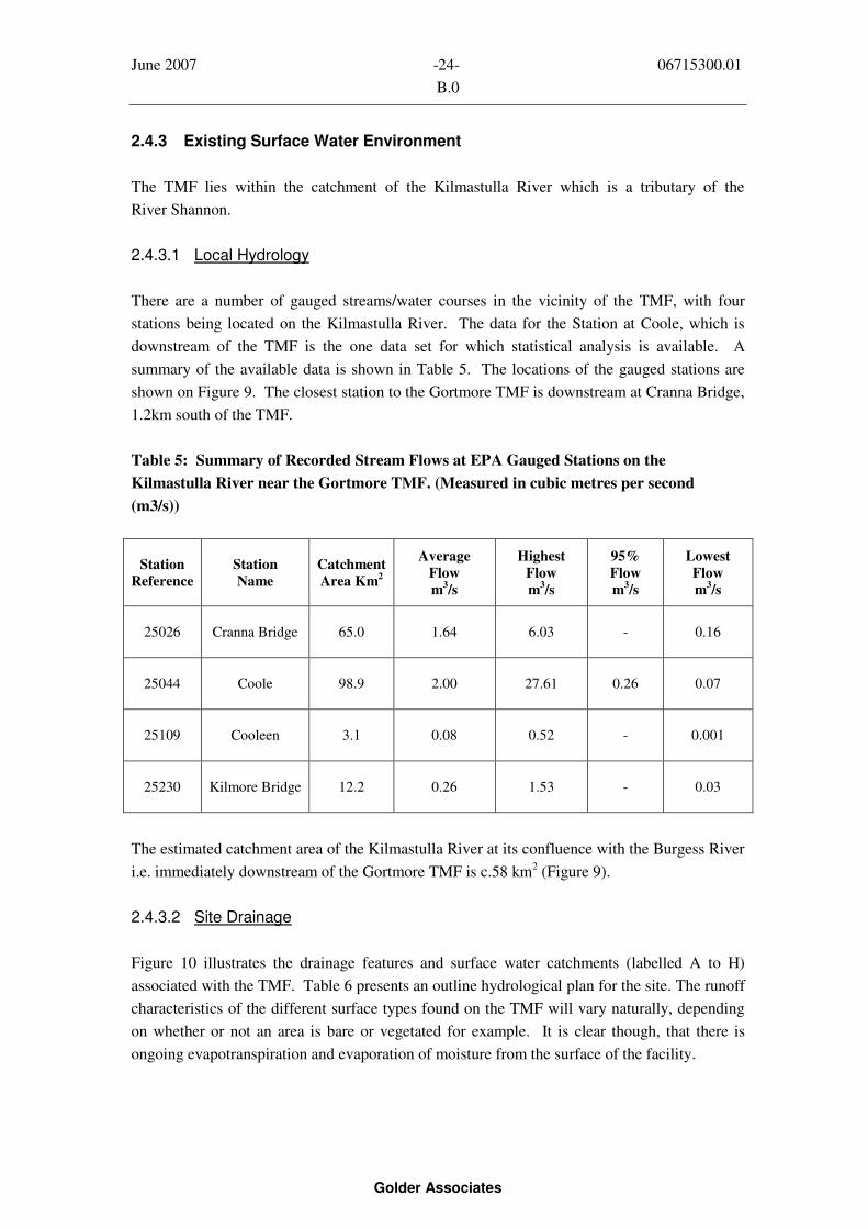
June 2007 -24- 06715300.01
B.0
Golder Associates
2.4.3 Existing Surface Water Environment
The TMF lies within the catchment of the Kilmastulla River which is a tributary of the
River Shannon.
2.4.3.1 Local Hydrology
There are a number of gauged streams/water courses in the vicinity of the TMF, with four
stations being located on the Kilmastulla River. The data for the Station at Coole, which is
downstream of the TMF is the one data set for which statistical analysis is available. A
summary of the available data is shown in Table 5. The locations of the gauged stations are
shown on Figure 9. The closest station to the Gortmore TMF is downstream at Cranna Bridge,
1.2km south of the TMF.
Table 5: Summary of Recorded Stream Flows at EPA Gauged Stations on the
Kilmastulla River near the Gortmore TMF. (Measured in cubic metres per second
(m3/s))
Station
Reference
Station
Name
Catchment
Area Km2
Average
Flow
m3/s
Highest
Flow
m3/s
95%
Flow
m3/s
Lowest
Flow
m3/s
25026 Cranna Bridge 65.0 1.64 6.03 - 0.16
25044 Coole 98.9 2.00 27.61 0.26 0.07
25109 Cooleen 3.1 0.08 0.52 - 0.001
25230 Kilmore Bridge 12.2 0.26 1.53 - 0.03
The estimated catchment area of the Kilmastulla River at its confluence with the Burgess River
i.e. immediately downstream of the Gortmore TMF is c.58 km2
(Figure 9).
2.4.3.2 Site Drainage
Figure 10 illustrates the drainage features and surface water catchments (labelled A to H)
associated with the TMF. Table 6 presents an outline hydrological plan for the site. The runoff
characteristics of the different surface types found on the TMF will vary naturally, depending
on whether or not an area is bare or vegetated for example. It is clear though, that there is
ongoing evapotranspiration and evaporation of moisture from the surface of the facility.

June 2007 -25- 06715300.01
B.0
Golder Associates
Table 6: Hydrological Plan for the Site
Site
Drainage
Zone
Description Principal OutletsSurface
Area (m2)
A Top Surface of Tailings Storage Area Decant pond and tower 552,200
+B North-eastern dam wall, Settlement Ponds
A, B and C, wetlands (No 1 (engineered) &
No 2 (volunteer)) and a strip of ground
along toe of north-eastern wall
A breach in the wetland
directly into the Kilmastulla
River at Point No.1 and the
concrete flume at Point No.2
shown on Figure 10
49,700
C Strip of ground along Kilmastulla River
that drains into the River by overland flow
No point discharge 14,400
D Dam wall and seeps plus a strip of ground
along Kilmastulla River that drains in to
the River by overland flow and at 2 no.
overflows from a volunteer wetland (No 3)
At Point Nos. 3 and 4 shown
on Figure 10
29,900
E The dam wall and seeps plus a small area
of rough ground and volunteer wetland
(No 4)
At Point No.5 – an open
channel that drains the south-
western and north-western
perimeter of the TMF
13,800
F The dam wall, rough scrub area and toe
drains on the south-western side of the
tailings storage area downstream of a point
where an external drainage area discharges
into the perimeter collection system of the
TMF
At Point No.5 – an open
channel that drains the south-
western and north-western
perimeter of the TMF
32,800
G The dam wall, rough scrub area and toe
drains on the north-western side of the
tailings storage area
The discharge point of this
area is into the perimeter
collection system in area F
and ultimately at Point No.5
on Figure 10
23,800
H The dam wall, rough scrub area and toe
drains on the north-western side of the
tailings storage area
This area should drain to the
south through area G but the
drainage channel is blocked
17,900

June 2007 -26- 06715300.01
B.0
Golder Associates
The surface of the tailings slopes towards two depressions which form ponds; a permanent
pond referred to as the Tailings Pool and a seasonal pond referred to as the Winter Water Body
on Figure 8. The gradient of the tailings surface varies across the site, with a general slope
towards the two ponds of about 0.8%. The Tailings Pool varies in size in response to climatic
conditions and rainfall. In August 2006 the size of the pond was c.15,200m2
and in the
December 2006 the size of the pond was c.45,600m2. There was a difference in water level of
approximately 0.3m between the August 2006 survey and the December 2006 survey.
Surface drainage channels have been cut into the surface of the tailings to drain surface runoff
and water from the two ponds into the decant pond (Figure 8). The channel draining the
Tailings Pool is partially blocked and has a very flat gradient. There is a short but deep
channel that flows northwards toward the decant pond (against the slope of the tailings surface)
from the Winter Water Body.
The decant pond is a purpose built structure approximately 16m (W) x 66m (L) at its top. The
side slopes are sheeted with waste rock and stand at approximately 1(v) :1.4(h). The pond
slopes sharply from south to north to a decant tower. The tower is essentially a four sided
reinforced concrete structure with an opening of approximately 0.9m in which timber weir
boards have been set to control the water level in the pond. The decant tower is connected to a
concrete pipeline, c.500mm ID that is buried beneath the tailings and falls to the north to an
outlet sump a few metres beyond the outer toe of the dam. This concrete pipeline is
approximately 139m in length and has a gradient of approximately 0.6%.
This pipeline discharges into a concrete sump which is in poor repair and is often overwhelmed
with ponded water. A concrete pipeline (now damaged and leaking) laid on the ground joins
the decant sump to the former Settlement Ponds in the northeast corner of the site. The
outflow from the Settlement Ponds is into a volunteer (naturally occurring, (has developed
itself overtime, little evidence of man-made construction, lining etc)) wetland (Wetland No. 2)
at the extreme northeast corner of the TMF. Not all of the TMF water discharges via these
Settlement Ponds; some of it short circuits the ponds and flows through Wetlands No. 1 and 2
then along a southwest flowing perimeter collector drain on the east side of the TMF to an
outfall consisting of a constructed concrete flume located just north of the main access ramp to
the TMF (Figure 8).
For the purpose of this report, discharges from the site were estimated by the mean section
method at three surface water discharge locations at the perimeter of the TMF (Figure 8). At
each of these locations a pressure transducer has been installed to measure water levels on an
hourly basis. The channel cross sections have been surveyed and water velocities measured at
each of the locations using a ‘Valeport’ velocity meter. The results of the monitoring
programme are indicated in Table 7 below.

June 2007 -27- 06715300.01
B.0
Golder Associates
Table 7: Recently (Dec. 2006 – May 2007) Measured Flows in Surface Water Features at
Gortmore (m3/s)
Date SW2 Decant Tower SW10 Flume SW12 South Corner TMF
07/12/06 0.0140
13/12/06 0.0127 0.0145
20/12/06 0.0072 0.0145
03/01/07 0.0102 0.0145
04/01/07 0.0189
10/01/07 0.0156 0.0197
29/01/07 0.0046
28/03/07 0.0031 0.0105
03/04/07 0.0023 0.0060
28/03/07 0.0005
24/05/07 0.0000 0.0015 0.0020
2.4.4 Geological and Hydrogeological Conditions
2.4.4.1 Aquifer Classification and Vulernability
Geologically the TMF is situated at the western end of the Kilmastulla syncline, with the
hillside to the south largely comprising Devonian sandstones and the lowlands to the north
underlain by Carboniferous limestones. The groundwater potential and vulnerability of the
various lithologies in the Silvermines area have been classified in terms of groundwater
protection zones. Hydrogeological mapping by the Geological Survey of Ireland (GSI) around
the TMF has classified the underlying substrate as having ‘High to Low’ vulnerability
(Figure 11). In other areas of the country the formation underlying the TMF, the
Ballysteen Formation, is generally classified as a ‘locally important aquifer, bedrock which is
moderately productive only – local areas’ (Figure 12).
2.4.4.2 Site Specific Groundwater Flow Conditions
From previous work and subsequent investigations made by Golder it is postulated that
groundwater flow would normally follow a subdued form of the surface topography and that
June 2007 -28- 06715300.01
B.0
Golder Associates
drainage across the general ‘study’ area would be northwards towards the Kilmastulla river and
then south-westward, following the river valley towards the Shannon (Figure 13).
Supplementary ground investigations carried out during October and November 2006 indicate
that the tailings ranges in thickness from between about 8m and 10m, and overlies natural
deposits of mainly silty/clayey glacial till, with sands and gravels underlying the glacial till in
boreholes BH2C/D-GORT-06 and BH4C/D-GORT-06. The native overburden encountered in
the perimeter boreholes was found to range in thickness from between 2.2m and 8.7m. The
boreholes drilled in 2001 (TMF1/SRK/01 to TMF4/SRK/01) encountered an estimated
thickness of overburden of between 2m and 13m overlying bedrock (limestone of the
Ballysteen Formation).
Water levels were measured in the boreholes/monitoring wells following installation. The
water-table in the tailings near the dam wall is estimated to be between 1m and 2m below the
tailings surface. The permanent pool and vegetation on the surface of the TMF indicates that
the water-table is close to or at surface moving inward from the perimeter to the centre of the
TMF. Water level readings in the monitoring well pairs (6) that were sealed deep and shallow
in the tailings indicate downward vertical gradients and hence downward seepage along the
dam walls of the TMF. The vertical hydraulic gradients range between 0.23 and 0.33 in
boreholes BH2A/2B-GORT-06, BH4A/4B-GORT-06 and BH5A/5B-GORT-06. In boreholes
BH1A/1B-GORT-06 and BH6A/6B-GORT-06 the vertical hydraulic gradient is between
0.6 and 0.7 respectively.
The hydraulic conductivity (permeability) (K) of the tailings has been estimated from gradation
analysis and one triaxial permeability test for samples taken from the tailings surface
boreholes. The K value for the tailings close to the dam wall is in the range of 1 x 10⁻⁷
and 1x
10-8
m/sec, with the gradation of the tailings being finer and less permeable near the centre of
the TMF. In addition, due to the nature of the deposition of the tailings its horizontal
permeability is expected to greater than its vertical permeability.
The downward seepage in the tailings around the edge of the TMF is being seen as seeps at the
external toe of the dam. However, based on the computed downward gradients (taken as
0.5 for computations purposes) and an estimated hydraulic conductivity of 5 x 10⁻⁸
m/sec, the
downward seepage around the perimeter of the TMF is estimated to be in the order of
0.0020 m3
per day per square metre. It is estimated that the area along the top of the dam wall
that is contributing to seepage at the toe is approximately 25m wide or 70,000 m2. The
estimated seepage flow at the toe of the dam wall from the tailings is therefore estimated to be
in the range of 75m3
to 125m3
per day. It should be noted that rain falling directly onto the
outer surface of the dam wall will also be contributing to the seepage that is visible at the toe of
the dam wall. It is estimated that direct rainfall on the dam wall will contribute an additional
150m3
to 175m3
per day. Further within the TMF the tailings will be less permeable as finer
grained tails were deposited towards the centre of the TMF, in particular beneath the
Tailings Pool and the Winter Water Body (Figure 8). As a result it is expected that the vertical

June 2007 -29- 06715300.01
B.0
Golder Associates
hydraulic gradients are less and therefore the downward seepage is less towards the centre of
the facility, when compared to the seepage conditions around the perimeter of the TMF.
Groundwater levels in bedrock monitoring boreholes drilled around the TMF range from
between just ground level to about 3m below ground level (Figure 8). Table 8 below
summarizes the groundwater levels measured in a total of 7 boreholes drilled in the vicinity of
the TMF by Golder (2006) and SRK (2001).
Table 8: Summary of Groundwater Levels from Bedrock Monitoring Boreholes
(11th
January 2007)
Borehole Number Height Top of Casing (TOC) (mAOD)
Groundwater
Depth Below
TOC (m)
Groundwater Level (mAOD)
TMF1/SRK/01 49.70 0.39 49.31
TMF2/SRK/01 48.98 1.99 46.99
TMF4/SRK/01 48.79 0.01 48.78
BH1D-GORT-06 51.37 3.16 48.21
BH2D-GORT-06 49.14 0.00 49.14
BH4D-GORT-06 49.42 0.00 49.42
BH5D-GORT-06 48.98 1.77 47.21
These results suggest a slight horizontal hydraulic gradient of 0.001 to 0.003 from northeast to
southwest as measured in the monitoring wells installed in the upper 15m of bedrock
(Figure 13).
2.4.5 Water Balance
A simple water balance has been prepared for the TMF based on a conceptual model shown in
Figure 14. Table 9 presents the estimated water balance for the TMF.

June 2007 -30- 06715300.01
B.0
Golder Associates
Table 9: Estimated Water Balance for Average Year
Item Units TSA
Downstream
Slopes
TSA Top
of Walls
(25m
width
from
edge)
TSA
Main
Surface
Area
TSA
Total
External
Area
around
TSA
Totals
for
TMF
Area m2
52,500 70,000 482,000 604,500 134,000 738,500
Total Rainfall –
Average at
Curreeny: (1955 -
2006)
mm/year 1,675 1,675 1,675 1,675 1,675 1,675
Potential
Evapotranspiration
at Birr: (1955 -
2006)
mm/year 507 507 507 507 507 507
Net Rainfall
Average
mm/year 1,168 1,168 1,169 1,168 1,168 1,168
Net Discharge m3/year 61,373 81,830 563,458 706,661 156,646 863,307
Estimated Surface
Runoff
%
m3/year
95
58,304
70
57,281
80
450,766
80
566,351
85
133,149 699,500
% 5 30 20 20 15Estimated
Infiltration m3/year 3,069 24,549 112,692 140,309 23,497 163,806
m3/year 61,373 24,549 0 85,922 0 85,922Estimated
Discharge to Toe
of Dam from TSA
Only
l/sec 1.95 0.78 0 2.72 0 2.72
m3/year 61,373 81,830 450,766 593,969 133,149 727,118Estimated
Discharge to
Surface Waterl/sec 1.95 2.59 14.29 18.83 4.22 23.06
m3/year 0 0 112,692 112,692 23,497 136,189Estimated
Discharge to
Groundwaterl/sec 0 0 3.57 3.57 0.75 4.32
(TSA* = Tailings Storage Area within the TMF)
2.5 Water Quality
2.5.1 Introduction
In order to prepare the detail design solution based on the Conceptual Plan presented in the
SRK Phase IV Report, Golder undertook further investigation of the waters around the TMF.
The results of these investigations and existing water quality data from earlier studies are
considered in this section.
Surface waters in and adjacent to the site have been monitored by a number of parties
(including the EPA, NTCC, IAG and SRK) since 1999. Very little detailed information on
groundwater had been collected in the Silvermines area prior to SRK’s collation and collection
of additional information during their Phase I and Phase II Studies. Additional sampling and
analysis of surface and ground water was undertaken as part of this report in order to:

June 2007 -31- 06715300.01
B.0
Golder Associates
Provide a current and more thorough understanding of possible contaminants in the
Gortmore aquatic environment, particularly as regards elevated heavy metal
concentrations; and
Make recommendations, where relevant, in relation to the results obtained as regards
the detailed design of the remediation solution at Gortmore and development of any
required mitigation works during the remediation and post remediation phases of the
project (Section 4.5).
2.5.2 Groundwater Sampling and Analysis Methodology
On reviewing the available information from the previous studies, a supplementary measuring
and sampling programme was designed and implemented to provide baseline data for the
design of the remediation works and any future environmental monitoring programmes in the
area.
Supplementary measuring and sampling of groundwater included:
Drilling of additional boreholes to aid in the monitoring of the integrity of the dam
walls by measuring the phreatic surface of the groundwater around the TMF;
Taking groundwater measurements to help refine the groundwater flow model around
the TMF;
Analysis of samples taken to look at the possibility of leachate escaping from the TMF
into the surrounding groundwater; and
Collection of information to aid in the calculation of a water balance for the site.
2.5.2.1 Groundwater Sampling
Groundwater samples were collected from 23 monitoring points in the vicinity of the TMF.
The locations of these wells are listed in Table 10. Both shallow and deep wells around the
perimeter of the TMF were sampled. This included water in the tailings material (A = 5m
depth, B = Bottom of tailings) and at the toe of the embankment (C / S = Overburden /
Shallow, D = Bedrock / Deep). Sample locations were selected in order to show both the
variability in the tailings material as well as the impact of seepage on the water-table
(Figure 8).

June 2007 -32- 06715300.01
B.0
Golder Associates
Table 10: Groundwater Monitoring Locations
Sample Id Grid Ref. Site Description
BH1A-GORT-06 E180169 N172497 Tailings (Shallow) 5m - South-east Side
BH1B-GORT-06 E180174 N172495 Tailings (Deep) - South-east Side
BH1C-GORT-06 E180195 N172474 Toe (Shallow) Overburden – South-east Side
BH1D-GORT-06 E180195 N172474 Toe (Deep) Bedrock - South-east Side
BH2A-GORT-06 E180202 N172840 Tailings (Shallow) 5m - Eastern Side
BH2B-GORT-06 E180206 N172845 Tailings (Deep) - Eastern Side
BH2C-GORT-06 E180245 N172863 Toe (Shallow) Overburden - Eastern Side
BH2D-GORT-06 E180245 N172863 Toe (Deep) Bedrock – Eastern Side
BH3A-GORT-06 E179826 N173122 Tailings (Shallow) 5m - Northern Corner
BH3B-GORT-06 E179827 N173116 Tailings (Deep) - Northern Corner
TMF1(S)/SRK/01 E179827 N173165 Toe (Shallow) Overburden - Northern Corner
TMF1(D)/SRK/01 E179827 N173165 Toe (Deep) Bedrock - Northern Corner
BH4A-GORT-06 E179573 N172816 Tailings (Shallow) 5m - North-west Side
BH4B-GORT-06 E179568 N172820 Tailings (Deep) - North-west Side
BH5A-GORT-06 E179537 N172313 Tailings (Shallow) 5m - South-west Side
BH5B-GORT-06 E179532 N172311 Tailings (Deep) - South-west Side
BH5C-GORT-06 E179504 N172299 Toe (Shallow) Overburden – South-west Side
BH5D-GORT-06 E179504 N172299 Toe (Deep) Bedrock - South-west Side
TMF2(S)/SRK/01 E179446 N172310 Toe (Shallow) Overburden – South-west Side
TMF2(D)/SRK/01 E179446 N172310 Toe (Deep) Bedrock - South-west Side
BH6A-GORT-06 E179861 N172220 Tailings (Shallow) 5m - Southern Side
BH6B-GORT-06 E179862 N172214 Tailings (Deep) - Southern Side
TMF4(D)/SRK/01 E179873 N172179 Toe (Deep) Bedrock - Southern Corner
Sampling was conducted during the week beginning the 14th
November. Samples were taken in
accordance with Golder Procedure No. 26: Groundwater Sampling (Appendix D1). Field
monitoring equipment was used to measure water depths, pH, conductivity and dissolved
oxygen.
2.5.2.2 Groundwater Laboratory Analysis
Along with the field data gathered, samples were submitted to the laboratory (Alcontrol
Laboratories, Dublin) for comprehensive analyses. The following parameters were determined
for each sample taken:
Depth, temperature, pH, Conductivity, Dissolved oxygen, Suspended solids;
Major Cations: Calcium, Magnesium, Potassium, Sodium, Ammonium;
Major Anions: Alkalinity, Fluoride, Chloride, Nitrite, Nitrate, Phosphate, Sulphate;
and
Metals (Dissolved and Total): Lead, Zinc, Cadmium, Arsenic, Chromium, Copper,
Iron, Manganese, Nickel, Mercury, Aluminium, Barium, Silver, Thallium and Tin
In order to determine dissolved metals, samples were filtered through a 0.45μm filter, acidified,
and then analyzed. Where total metals were determined, samples were acidified first, and then
filtered prior to being analyzed. Table 11 lists the analytical methods used and associated
limits of detection.

June 2007 -33- 06715300.01
B.0
Golder Associates
Table 11: Analytical Methods used and Limits of Detection
Parameter Instrument Detection Limit
pH Meter
Conductivity (at 25°C) Meter 0.014mS/cm
Dissolved oxygen Meter 0.1mg/L
Total Suspended Solids Gravimetric 10mg/L
BOD1
5-day ATU 2mg/L
COD1
Spectrophotometry 15mg/L
Calcium ICP-MS 120μg/L
Magnesium ICP-MS 100μg/L
Ammoniacal Nitrogen (as N) Spectrophotometry 0.2mg/L
Potassium Flame Photometry 0.2mg/L
Sodium Flame Photometry 0.2mg/L
Chloride KONE 1mg/L
Fluoride KONE 0.1mg/L
Nitrate (as NO3) KONE 0.3mg/L
Nitrite (as NO2) KONE 0.05mg/L
Orthophosphate (as PO4) KONE 0.03mg/L
Sulphate KONE 3mg/L
Total Alkalinity (as CaCO3) Titration 1mg/L
Lead, Zinc, Cadmium, Arsenic,
Chromium, Copper, Manganese,
Nickel, Barium, Thallium, Tin
ICP-MS 1μg/L
Iron, Aluminium, Silver ICP-MS 2μg/L
Boron ICP-MS 3μg/L
Mercury TOTAL ICP-IRIS 0.05mg/L
Mercury DISSOLVED CV AA 0.05μg/L1
BOD and COD on surface water only
The reliability of all analytical results was checked using ion charge balances. Data was
deemed to be acceptable where the difference between anions and cations (in meq/L) was
reported at 10%. In addition, comparisons were made between the dissolved and total metal
concentrations determined using the ICP-MS. Furthermore, calibration curves and the internal
quality control charts for standards run were also analyzed. These were found to be
acceptable. Although the laboratory validated the data, some small discrepancies appeared in
relation to total and dissolved metal concentrations. These differences were attributed to
sub-sampling discrepancies and where they occurred that sample was not considered.
2.5.3 Surface Water Sampling Analysis and Methodology
Three types of surface sample site locations were selected (Figure 8):
1. Control sites: these locations are not believed to be impacted by the TMF, either
because they are located upstream of the TMF or are located on a separate river
catchment. These sites are likely to be influenced by the underlying geology;
2. Tailings-affected sites: these are located within or immediately adjacent to the TMF;
and

June 2007 -34- 06715300.01
B.0
Golder Associates
3. Downstream sites: two downstream locations were selected along the
Kilmastualla River, as all flows and seeps from the TMF drain to this river.
2.5.3.1 Surface Water Sampling
Surface water samples were collected from 19 locations (including pools/ponds, sumps, seeps
and streams) in the vicinity of the TMF (Figure 8). These locations are listed in Table 12 and
a number of the locations are shown in photographs in Appendix E. Appropriate sample
locations were selected in order to show both the background concentrations in the area, and
the impact of possible infiltration through and seepage from the TMF. Sampling was
conducted on the 14th
of November 2006, during “normal” flow conditions. Samples were
taken in accordance with Golder Procedure No. 31: Surface Water Sampling (Appendix D2).
2.5.3.2 Surface Water Laboratory Analysis
In addition to field measurements, samples were submitted to the laboratory
(Altcontrol Laboratories, Dublin) for comprehensive analyses. In the laboratory, analysis was
similar to that for the groundwater (See Section 2.5.2.2). Analysis was also undertaken for
BOD and COD. The surface water data was also subjected to similar quality control
procedures. However, where depth was measured in the groundwater samples, flows were
taken for the surface water samples.

June 2007 -35- 06715300.01
B.0
Golder Associates
Table 12: Current Surface Water Sampling Locations (Figure 8)
Sample Id Grid Ref. Site Description
Control sites
SW13-GORT-GA E179496 N172186 River entering Kilmastulla from north-west (along
western wall of TMF) – Burgess River
SW15-GORT-GA E181509 N172660 Kilmastulla River (upstream) entering main channel south
of orange discharge at big tree
SW16-GORT-GA E181842 N174423 River (upstream) entering main channel north of orange
discharge at big tree
SW17-GORT-GA E180548
N173070
River upstream of where seepage drain from retention
ponds enters
SW3-SH-GA E181304
N171651
Yellow River, downstream of Yellow Bridge
Tailings-affected sites
SW1-GORT-GA E179772 N172648 Pool on TMF surface
SW2-GORT-GA E180005 N172874 Decant pond on surface of TMF
SW3-GORT-GA E180112 N172982 Discharge pipe/sump at toe of TMF, where water enters
retention ponds
SW4-GORT-GA E180313 N172651 Rectangular pond in wetland / toe drain along south-east
wall of TMF (where wall is burnt)
SW5-GORT-GA E180367 N172658 Orange discharge from rectangular pond (SW4) into river
(under big tree)
SW6-GORT-GA E180389 N172795 Seepage drain to north-east of retention ponds, at river
discharge point
SW7-GORT-GA E180376 N172810 “Discharge” water from 3rd
retention pond (taken at
southern corner)
SW8-GORT-GA E180350 N172863 “Discharge” water from 2nd retention pond (taken at
overflow to 3rd
pond)
SW9-GORT-GA E180302 N172895 “Discharge” water from 1st retention pond (taken at
overflow to 2nd
pond)
SW10-GORT-GA E180195 N172412 Discharge from wetland / toe drain along south-east wall
of TMF
SW12-GORT-GA E179567 N172130 Toe drain along south-west wall of TMF, upstream of
confluence with Kilmastulla
SW18-GORT-GA E180451 N173047 Field / farm drain feeding into river that flows from
upstream of where seepage drain from retention ponds
Downstream sites
SW11-GORT-GA E180198
N172360
Kilmastulla river downstream of where discharge from
wetland / toe drain along south-east wall of TMF enters
SW14-GORT-GA E179337 N172170 Kilmastulla river downstream of confluence (& southern-
most corner of TMF)

June 2007 -36- 06715300.01
B.0
Golder Associates
2.5.4 Stream Sediment Sampling and Analysis Methodology
2.5.4.1 Sampling
Stream sediment samples were collected from 8 locations in the vicinity of the TMF (Figure 8).
These locations are listed in Table 13. All but one of these locations is on the
Kilmastulla River, or feeds into the Kilmastulla River near the TMF. Sample locations were
selected on the proviso that they might show both the background concentrations in the area,
and the impact of possible infiltration through and seepage from the TMF. It is envisaged that
re-sampling at a later date will reveal reduced impacts as a result of the
remediation/rehabilitation of the TMF.
Table 13: Current Sediment Sampling Locations
Sample Id Grid Ref. Site Description
SS1-GORT-GA E179499 N172131Under footbridge on Kilmastulla river near south-western
corner of TMF
SS2-GORT-GA E179495 N172185 Burgess river, upstream of confluence with Kilmastulla
SS3-GORT-GA E179563 N172144 Toe drain sump along south-west wall of TMF
SS4-GORT-GA E180172 N172409Discharge from wetlands & toe drain along south-east
wall of TMF
SS5-GORT-GA E180357 N172699Orange discharge from rectangular pond (SW4) into
Kilmastulla river (under big tree)
SS6-GORT-GA E180390 N172791Seepage drain to north-east of retention ponds, at river
discharge point
SS7-GORT-GA E179910 N172811Surface drain between pool and decant pond on surface of
TMF
SS8-GORT-GA E181509 N172660Erinagh Bridge, upstream of the TMF on the Kilmastulla
river
Sampling was carried out on the 15th
of January 2007, following a relatively wet December.
Samples were taken in accordance with the FOREGS guidelines. Composites were made up
from approximately 5 grab samples taken over a 4-5m stretch. Samples were wet-sieved in the
field, to a 150μm size fraction, using water from the stream being sampled. They were allowed
to settle overnight, prior to the decant water being poured off and the sample then transferred
to a 250g glass jar. Samples were then dispatched to OMAC Laboratories in Galway for
analysis. Sampling equipment was decontaminated between each sample.
2.5.4.2 Stream Sediment Laboratory Analysis
The following analyses were performed on the samples (Table 14):
pH;
Major Cations: Calcium, Magnesium, Potassium, Sodium;
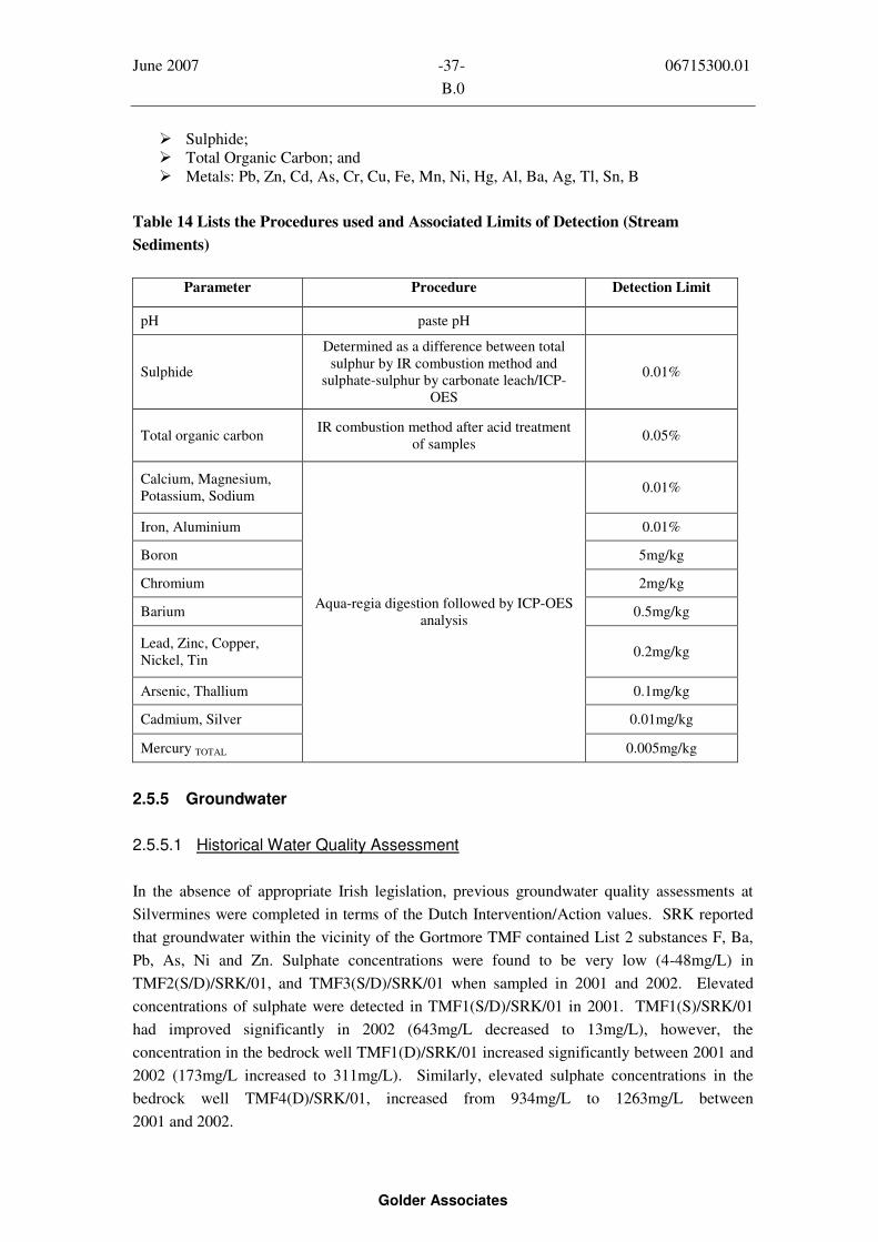
June 2007 -37- 06715300.01
B.0
Golder Associates
Sulphide;
Total Organic Carbon; and
Metals: Pb, Zn, Cd, As, Cr, Cu, Fe, Mn, Ni, Hg, Al, Ba, Ag, Tl, Sn, B
Table 14 Lists the Procedures used and Associated Limits of Detection (Stream
Sediments)
Parameter Procedure Detection Limit
pH paste pH
Sulphide
Determined as a difference between total
sulphur by IR combustion method and
sulphate-sulphur by carbonate leach/ICP-
OES
0.01%
Total organic carbonIR combustion method after acid treatment
of samples0.05%
Calcium, Magnesium,
Potassium, Sodium0.01%
Iron, Aluminium 0.01%
Boron 5mg/kg
Chromium 2mg/kg
Barium 0.5mg/kg
Lead, Zinc, Copper,
Nickel, Tin0.2mg/kg
Arsenic, Thallium 0.1mg/kg
Cadmium, Silver 0.01mg/kg
Mercury TOTAL
Aqua-regia digestion followed by ICP-OES
analysis
0.005mg/kg
2.5.5 Groundwater
2.5.5.1 Historical Water Quality Assessment
In the absence of appropriate Irish legislation, previous groundwater quality assessments at
Silvermines were completed in terms of the Dutch Intervention/Action values. SRK reported
that groundwater within the vicinity of the Gortmore TMF contained List 2 substances F, Ba,
Pb, As, Ni and Zn. Sulphate concentrations were found to be very low (4-48mg/L) in
TMF2(S/D)/SRK/01, and TMF3(S/D)/SRK/01 when sampled in 2001 and 2002. Elevated
concentrations of sulphate were detected in TMF1(S/D)/SRK/01 in 2001. TMF1(S)/SRK/01
had improved significantly in 2002 (643mg/L decreased to 13mg/L), however, the
concentration in the bedrock well TMF1(D)/SRK/01 increased significantly between 2001 and
2002 (173mg/L increased to 311mg/L). Similarly, elevated sulphate concentrations in the
bedrock well TMF4(D)/SRK/01, increased from 934mg/L to 1263mg/L between
2001 and 2002.

June 2007 -38- 06715300.01
B.0
Golder Associates
2.5.5.2 Current Water Quality Assessment
Results of ground water quality analyses from samples taken from the boreholes in the vicinity
of the TMF, were compared against the EPA Interim Guideline Values for the Protection of
Groundwater. Sample locations are shown in Figure 15. All data has been tabled and plotted,
along with the above-mentioned guideline values (Appendix D3).
As expected water quality in most of the wells drilled into the tailings material itself is
dominated by high concentrations of sulphate (~2287mg/L), along with variable concentrations
of calcium (413 – 602mg/L) and magnesium (156 – 477mg/L). Given the nature of the tailings
material, and locations of the boreholes on top of and adjacent to the toe of the TMF, it is not
surprising that all of these major ions significantly exceed the EPA Interim Guideline values
for groundwater. Potassium concentrations also exceed the EPA Interim Guideline values in
the tailings water (Average ~13.9mg/L). Major ion dominance can be seen in the
Piper diagram in Chart 2. Near-neutral pH was recorded, as was very high electrical
conductivity (up to 4.1mS/cm) in all of these samples. With an average of 4.4mg/L O2,
dissolved oxygen was relatively low suggesting that, as expected, limited opportunities exist
for oxidation of the sulphide material in wet tailings at depth in the TMF.
Chart 2: Piper Diagram Showing Major Ion Chemistry of Ground Water Samples
Buffering capacity has been estimated based on alkalinity measurements. These are highly
variable in the tailings, with relatively low concentrations occurring in BH1A/B-GORT-06
(~85mg/l as CaCO3) and BH2A/B-GORT-06 (~75mg/L as CaCO3). These are located on the
south-eastern side and eastern corner of the TMF near the retention ponds and wetlands
80
60
40
20 2
0
40
60
80
20
40
60
80 80
60
40
20
20
40
60
80
20
40
60
80
Ca Na+K HCO3 Cl
Mg SO4
L
L
L
L
L
L
L
L
L
L
L
L
L
L
L
D
D
D
D
D
D
D
D
D
D
D
D
D
D
D
D
D
D
H
H
H
H
H
H
H
H
H
H
H
H
C
C
C
C
C
C
CC
C
C
C
C
C
C
C
LegendLegend
L Gortmore Tailings Shallo
D Gortmore Tailings Deep
H Gortmore Toe Shallow
C Gortmore Toe Deep

June 2007 -39- 06715300.01
B.0
Golder Associates
adjacent to the Kilmastulla River. Significantly more buffer capacity can be found along the
north-western side in BH4A/B-GORT-06 (~360mg/L as CaCO3).
Metal concentrations in the tailings pore water are also highly variable, with many of the
metals analyzed being below detection limits. Generally speaking, however, metal
concentrations tend to be slightly lower in BH1A/B-GORT-06 and BH6A/B-GORT-06 when
compared to the other boreholes into the tailings material.
A review of the data available for wells drilled around the toe of the dam shows that many of
the wells exhibit significant concentrations of sulphate (Table 15). Exceptions include
TMF1(D)-SRK-01, TMF2(S)-SRK-01 and TMF2(D)-SRK-01. This suggests that the
groundwater flowing over the bedrock at the northern corner, and along the south-western
boundary of the TMF did not contain elevated levels of sulphate at time of sampling. The
shallow well (BH2C-GORT-06) at the toe of the dam on its eastern side, indicated relatively
low levels of sulphate when sampled in 2006. The overburden and bedrock well (BH1C/D-
GORT-06) drilled close to the Kilmastulla River showed sulphate concentrations of over
2000mg/L when sampled in 2006. The shallow well drilled close to the south-western toe of
the dam (BH5C-GORT-06) also showed elevated sulphate values (2212mg/L), although these
concentrations were not detected in the adjacent bedrock well (BH5D-GORT-06) or on the
other side of the Burgess River (TMF2(S)/(D)-SRK-01). Similarly, elevated sulphate
concentrations (649mg/L) were detected in the shallow well at the northern corner of the TMF
(TMF1(S)-SRK-01), but this was not mirrored in the bedrock well at this location (TMF1(D)-
SRK-01). Although all wells presented with near-neutral pH, their conductivities mirrored the
sulphate trends discussed above.
The wells along the south-eastern (BH1C/D-GORT-06) and south-western (BH5C-GORT-06)
walls displayed Zn, Ni and Al concentrations close to or in excess of the EPA Interim
Guideline Values. Chromium is also elevated above the EPA Interim Guideline Value in
TMF4(D)/SRK/01; as well as being elevated in some of the other bedrock wells (BH1C-
GORT-06, TMF1(S)/SRK/01, TMF1(D)/SRK/01 and BH5C-GORT-06). In addition,
Fe and Mn also exceed the EPA Interim Guideline Values in all the bedrock wells. On-going
monitoring of these wells is recommended as part of the long-term environmental monitoring
programme for the Silvermines area.
Such metal concentrations are not unexpected in boreholes adjacent to the TMF. However,
groundwater monitoring in the general Silvermines area has not shown any evidence of
significant impact on ant potential groundwater recptors.

June 2007 -40- 06715300.01
B.0
Golder Associates
Table 15: Water Quality in Overburden and Bedrock Boreholes along TMF Perimeter
(November 2006)
Parameter (mg/L) SO4 Zn Ni Al Fe Mn Cr
EPA Interim
Guideline Values200 0.1 0.02 0.2 0.2 0.05 0.03
BH1C-GORT-06 2128 8.825 0.279 0.323 5.377 1.030 1.288
BH1D-GORT-06 2002 2.876 0.051 0.449 1.469 1.365 0.009
BH2C-GORT-06 421 0.048 0.012 0.257 0.919 1.366 0.009
TMF1(S)/SRK/01 649 0.034 0.108 0.913 2.066 0.493 0.317
TMF1(D)/SRK/01 9 0.036 0.059 3.916 3.973 0.130 0.208
BH5C-GORT-06 2212 5.386 0.153 0.028 0.927 5.307 0.214
BH5D-GORT-06 243 0.039 0.029 0.387 0.214 0.097 0.017
TMF2(S)/SRK/01 <3 0.041 0.018 0.231 0.415 0.152 0.038
TMF2(D)/SRK/01 6 0.055 0.030 0.574 0.890 0.787 0.044
TMF4(D)/SRK/01 1406 0.095 0.244 0.154 1.536 0.895 0.121
2.5.6 Surface Water
The Kilmastulla River runs along the south-eastern edge of the TMF site, from northeast to
southwest. The Burgess River runs along the south-west perimeter of the site, from north to
south. The site overview plan (Figure 8) shows the location of the surface water sampling
locations.
2.5.6.1 Historical Water Quality Assessment
As already mentioned, a number of surface water samples have been taken in the vicinity of
Gortmore over the years by; the IAG (September 1999), EPA (2000, 2001) and SRK
(May 2001). All these results can be found in the Silvermines Baseline Environmental
Monitoring Report (Golder Associates, 2007a), which has recently been compiled by
Golder Associates. A summary of the significant results in relation to the quality of the water
in the Kilmastulla River is given below. Additional monitoring of critical parameters and
locations is proposed during the next 12 months to produce additional seasonal data.
The Kilmastulla River has been routinely monitored by the EPA at Sites 0200 and 0300 since
January 1999 (Figure 8). Site 0200 is upstream of the TMF and the confluence with the
Yellow River, whilst 0300 is further downstream, halfway along the southern edge of the TMF
but still upstream of the Yellow river confluence. At both sites, the pH was ~8 and
EC ~820μS/cm, with similar chemistries. Average values indicated that at both sites, the only
parameters to be found in exceedance of the Irish Standards used (Surface Water Abstraction,
S.I. 294 of 1989) were Fe, Mn and Ba (Appendix D4). On this basis, the TMF is not adding
significantly to the metal load within the Kilmastulla River.
As part of the IAG study, two samples were collected from the Kilmastulla where it flows
alongside the TMF (i.e. SW14-IAG-99 and SW15-IAG-99, Figure 8). Sample SW14-IAG-99

June 2007 -41- 06715300.01
B.0
Golder Associates
was in a similar position to EPA routine monitoring location 0300, while SW15 was
downstream of the confluence of the Kilmastulla River with the Yellow River.
The data from SW14-IAG-99 is in close agreement with the EPA data from 0200 and 0300
where Al, Fe, Mn and Ba were found to be lower than at SW15-IAG-99. Lead values also
increased significantly downstream. This suggests that the Yellow River, which drains the
Shallee and Garryard workings is having a negative impact on the Kilmastulla.
Previous work carried out by SRK reported that at Cranna Bridge, further downstream of the
TMF, metal concentrations in the Kilmastulla River were within the range of the relevant
standards (EC Quality of Salmonid Waters Regulations - S.I. 293 of 1988 and EC Quality of
Surface Water Intended for Abstraction of Drinking Water Regulations - S.I. 294 of 1989),
apart from Ba, which was slightly elevated. Similar Ba concentrations were also found
upstream of the TMF and are thought to be associated with mineralization in the area, (the
Magcobar Barite Mine closed in 1992).
2.5.6.2 Current Water Quality Assessment
All surface water samples at Gortmore were initially assessed in terms of the EC Quality of
Salmonid Waters Regulations (S.I. 293 of 1988) and the EC Quality of Surface Water Intended
for Abstraction of Drinking Water Regulations (S.I. 294 of 1989) (A1 level). These are the
standards that have been used as the basis for treated water discharge limits in the
IPC Licences at The Lisheen Mine and Galmoy Mine with some exceptions as regards
Fe and Mn. They are also similar to the EPA BATNEEC Guidance Note for the Extraction of
Minerals (1997). In addition, these standards are referenced in the Silvermines Expert Group
Report (EPA 2004).
The ideal for an abandoned mine site(s) such as Silvermines would be to achieve such water
quality standards as far as reasonably practicable, given the site’s history and the unique
naturally occurring mineralogical conditions of the area. The standards will be used herein as
the target for compliance and modified where prudent and acceptable. The aim will be to
progress towards attainment. Where limits are imposed in both regulations, the
Salmonid Limit will be applied as it is considered more relevant, as no surface water
abstraction points are known on the Kilmastulla River down stream of Gortmore. All data has
been tabled and graphed in Appendix D4, along with the above-mentioned water quality
standards.
It is important to note that Section 9 of the Water Quality (Dangerous Substances) Regulations
of 2001 (S.I. 12 of 2001) may allow for an exemption from meeting the stringent standards set
out within the Dangerous Substances Regulations by December 2010, if compliance is not
feasible or likely to be disproportionately expensive.

June 2007 -42- 06715300.01
B.0
Golder Associates
Control Sites
Four control sites were sampled at Gortmore (Table 12, Figure 8). A fifth control site was
sampled from the Yellow river, near the Yellow bridge, downstream of the Garryard and
Shallee sites. Three of the streams sampled feed into the Kilmastulla River upstream of the
main Gortmore discharge point, but close to some of the Gortmore seeps. The confluence of
the fourth streams occurs near the south-west corner of the TMF. All four of these control sites
are characterized by very low electrical conductivity, ranging from 0.25mS/cm through
to 0.73mS/cm. The control sites are Ca-HCO3 dominated (Chart 3), and contain high
concentrations of alkalinity (i.e. 180 – 310mg/L as CaCO3) which provides good buffering
capacity. These streams are also characterized by high concentrations of barium, which is
known to occur naturally in the Silvermines area, and commonly exchanges for calcium.
Although these waters are calcium dominated, the calcium concentration in the control sites
was generally lower (average 84.2mg/L) than at the mine-affected sites (average ~198mg/L),
as was magnesium (~7.2mg/L and 105mg/L respectively).
Chart 3: Piper Diagram Showing Major Ion Chemistry of Surface Water Samples
Dissolved oxygen concentrations were well below the 6mg/L Salmonid Limit for the samples
taken. As water temperatures were not measured, it is uncertain whether the un-seasonally
warm weather at the time of sampling played a role. Although below legislated limits, nitrate
and some COD was detected in these waters. Significant quantities of nitrite and
orthophosphate were also measured. These are believed to be associated with agricultural
activity in the area. At ~32.8mg/L, sulphate concentrations were, as expected, well below the
legislated limits. Almost all trace metals analyzed were found to have very low concentrations,
80
60
40
20 2
0
40
60
80
20
40
60
80 80
60
40
20
20
40
60
80
20
40
60
80
Ca Na+K HCO3 Cl
Mg SO4
GORTMORE SURFACE WATER
A
A
A
A A
A
AA
A
AA
A
A A
A
A
A
A
A
A
A
AA
A
A
A
A
A
A
A
A
A
A
A
A
A
A
A
A
A
A
A
A
A
A
A
A
A
A A
A
A A
A
LegendLegend
A Gortmore Control
A Gortmore Affected
A Gortmore Downstream

June 2007 -43- 06715300.01
B.0
Golder Associates
in many cases close to or below detection limits. Exceptions to this include iron and
aluminium, which occur in variable concentrations across the Gortmore area.
Although the fifth control sample, from the Yellow River, is Ca-Mg-HCO3-SO4 dominated, the
sulphate concentrations are still well within the Salmonid (and Abstraction) Limits. This
sample contained elevated suspended solids (92mg/L), which appear to be associated with
elevated metals. Lead, zinc and iron all exceed the limits imposed by the legislation.
Tailings-affected Sites
A series of engineered (Wetland No.1) and volunteer wetlands (Wetlands No.2, No.3
and No.4) have developed around the Gortmore TMF (Figure 8). Water draining from the
Tailings Pool into the decant pond on the surface of the TMF, and down through the
overgrown wetlands (Wetlands No.1 and No.2) along the eastern and southern sides of the
facility, has slightly lower than neutral pH (6.1- 6.9), and generally low alkalinity (20-70mg/L
as CaCO3) suggesting limited buffer capacity. During periods of heavy rainfall after relatively
dry periods, water draining (‘flushed’) into the decant pond has been known to run acidic
(pH ~2). The only suspended solids detected in the analyses were in the waters flowing from
the decant pond (SW2-GORT-GA), entering the wetland and flowing into the small
rectangular pond (SW4-GORT-GA) (Figure 8). This suggests a relatively recent ‘flushing
event’ had occurred.
Water bodies affected by the tailings material were found to be Ca-Mg-SO4 dominated (Chart
3, with sample locations SW1-GORT-GA to SW5-GORT-GA shown on Figure 8) and
generally displayed electrical conductivity values well in excess of the 1mS/cm abstraction
limit.
Elevated concentrations of calcium and magnesium were observed in all tailings affected
waters. Maximum concentrations of these occurred in the waters flowing from the
decant pond through to the discharge from the rectangular pond (SW4-GORT-GA) (>200mg/L
Ca and >125mg/L Mg). Relatively high fluoride concentrations were also recorded in many of
the tailings affected waters. Sodium and chloride concentrations, however, were slightly lower
than in the control sites.
Due to exposure and oxidation of the sulphidic material in the TMF, water flowing across and
seeping through the facility into the wetland drains contains considerably high concentrations
of both sulphate (~938mg/L) and trace metals (specifically Pb, Zn, Cd, Mn, Ni, Th).
Insignificant concentrations of As were reported in the tailings-affected waters only and no
Hg or Ag was detected at all. Arsenic commonly co-precipitates with iron and therefore is
often not detected in near-neutral mine-affected waters.
As already mentioned, aluminium and iron varied from one location to the next. Slightly
higher concentrations, however, were found in the tailings-affected waters. Again, these are

June 2007 -44- 06715300.01
B.0
Golder Associates
expected to vary with acidification and re-neutralization reactions. The concentration of boron
was somewhat constant across all sample locations, albeit present in very low concentrations.
The exceptionally high manganese concentrations (1189 – 6628μg/L) in the Settlement Ponds
are of particular interest. Manganese is an indicator of acidification reactions
(i.e. changing pH). It does not drop out of solution until higher pH's are reached. Its presence
is used to indicate that acid rock drainage (ARD) reactions have occurred and a reaction
sequence is underway. In this sequence acidification is being buffered naturally but over time,
as alkalinity is used up, this situation will change. Manganese indicates that at some stage pH
had to be low enough for the metals to dissolve out but the natural neutralisation activity
produces waters with little or no metal and salts. It is proposed to remove the stagnant water
from the Settlement Ponds as part of the refurbishment of the wetland system.
A series of engineered and volunteer (natural) wetlands have developed around the TMF. The
northeast perimeter contains three Settlement Ponds and one engineered wetland and one
volunteer wetlands (Wetlands No.1 and No.2 respectively) (Figure 15). Settlement Ponds
A, B, and C are constructed settling basins, which include a clay soil liner and bermed
sidewalls. Wetland No.2 appears to be a volunteer wetland which has formed on its own near
collection ditches along the toe of the TMF. Water drains from the decant pond into
Wetland No.1, and continues through to the Settlement Ponds and Wetland No.2. In addition,
small seeps form the dam wall also enter the wetlands.
Major cations, such as calcium and magnesium, are seen to decrease in concentration along
with sulphate as the water flows through the ponds (SW9-GORT-GA through SW7-GORT-
GA). Trace metals, however, increase steadily. In terms of the regulatory limits, zinc,
cadmium, and manganese are of particular concern, although copper, nickel and thallium show
similar trends. All of these metals are present almost entirely in the dissolved rather than
particulate form, except possibly manganese. The behaviour of manganese has already been
discussed above.
Despite their stagnant appearance, it appears that low flow is currently occurring through
Settlement Ponds A, B, and C in a series configuration. These ponds are believed to be lined
with local clay. Wetlands No.1 and No.2, on the other hand, appear to have limited or no flow
controls, with water flowing into and out of these wetlands at a number of locations.
Refurbishment of the Settlement Ponds and the wetlands will ensure controlled management of
water flow through the whole of the wetland system before water is discharged into the
Kilmastulla River. An essential component of any water treatment process is flow control. In
general, successful treatment systems have one influent and one effluent location and minimal
loss of water from the system. Losses due to evaporation will occur.
During the summer months, the wetlands reveal significant vegetation; resembling marshes or
bogs which contain aerobic surface conditions and anaerobic subsurface conditions. For the
purposes of metal removal through formation of oxide precipitates, it is imperative that

June 2007 -45- 06715300.01
B.0
Golder Associates
wetlands remain aerobic. The principal difference between volunteer wetlands and engineered
wetlands is that wetlands engineered for metal removal are shallow enough to promote aerobic
conditions throughout the wetland profile. Volunteer wetlands which have both aerobic and
anaerobic horizons can alternately sequester and release metals on a seasonal basis.
An assessment of the Settlement Ponds (A, B & C) near the north-eastern corner of the TMF
suggests that these ponds are no longer effective as a series of “polishing” ponds. It is
proposed to partially infill these Settlement Ponds and reconstruct them to form additional
wetlands to those already in existence. Water flows through the wetlands and discharges into
the Kilmastulla River via the concrete flume at SW10-GORT-GA (Figure 8). The
water quality at the inlet SW3-GORT-GA and the outlet SW10-GORT-GA are shown in
Table 16. The existing wetlands appear to be removing Pb, Fe, Mn and Cd effectively with
limited Zn removal and no sulphate removal. The proposed capping of the surface of the TMF
and the refurbishment of the wetlands are expected to reduce the contaminant load to the
Kilmastulla River significantly.
Table 16: Wetland Water Quality (November 2006)
Parameter (mg/L)
Inlet to Wetlands (exit from
decant pond)
SW3-GORT-GA
Main Outlet to Kilmastulla
River
SW10-GORT-GA
Total Pb 0.232 0.001
Total Zn 6.56 3.60
Total Fe 3.33 <0.002
Dissolved Fe <0.002 <0.002
Total Mn 3.17 0.084
Sulphate 1169 1168
Total Cd 0.022 0.004
In addition to the main outlet to the Kilmastulla River (SW10-GORT-GA) there are numerous
uncontrolled flows from the wetlands particularly during wet weather which may have higher
metal concentrations than those recorded at SW10-GORT-GA.
Water flowing through the drain along the north-eastern side of the Settlement Ponds and
discharging into the Kilmastulla River (SW6-GORT-GA), and water flowing off the
south-western corner of the TMF into a toe drain (SW12-GORT-GA) also contain high
sulphate, but metal concentrations and alkalinity are generally similar to those observed at the
control sites. This is likely to be due to the scrubbing effects of the wetlands. A
farm/field drain (SW18-GORT-GA), flowing away from the Settlement Ponds to the north-
east, is not significantly impacted on by the tailings material or any seepage from the
Settlement Ponds.
Downstream sites
Not surprisingly, samples taken from the Kilmastulla River alongside the TMF (SW11-GORT-
GA) and downstream from it (SW14-GORT-GA) was classed as Ca-HCO3-SO4 dominant.

June 2007 -46- 06715300.01
B.0
Golder Associates
Although the waters discharging directly into the Kilmastulla River from the TMF drains and
uncontrolled wetland seepages (SW10-GORT-GA) do not meet proposed regulatory limits (EC
Quality of Salmonid Waters Regulations - S.I. 293 of 1988 and EC Quality of Surface Water
Intended for Abstraction of Drinking Water Regulations - S.I. 294 of 1989) for many of the
parameters determined (including conductivity, orthophosphate, sulphate, zinc, cadmium, iron
and manganese), there appears to be sufficient dilution capacity in the river at the present time
to reduce the conductivity, sulphate, zinc and cadmium to acceptable concentrations, as can be
seen when surface water samples taken from the Kilmastulla River both upstream (SW17-
GORT-GA) and downstream (SW14-GORT-GA) of the TMF (Figure 8) are compared with
those discharging from the TMF (Appendix D4). The uncontrolled seeps will be removed as
part of the refurbishment of the wetland system.
2.5.7 Stream Sediments
2.5.7.1 Historical Stream Sediment Assessment
The stretch of the Kilmastulla River which flows alongside the TMF is reported to be up to
8m in width, and up to 1m deep in the summer months. Consequently, the collection of
representative samples of stream bed sediment is difficult. This was noted during the
collection of two stream sediment samples (SS12 and SS13) in the IAG investigation. The
data from this investigation, was therefore viewed as potentially misleading by SRK.
Sediment collected upstream of the confluence between the Kilmastulla and Yellow rivers
contained elevated Zn, Ba and Pb. In comparison, the sample collected downstream contained
lower metal levels, all of which were below the Dutch Action values (e.g. Pb 57mg/kg, Zn
98mg/kg and Ba 189mg/kg). Sample locations are shown in Figure 8.
Due to the difficulties in collecting representative samples, previous workers did not include
sediment sampling of the Kilmastulla River. Sediment was, however, collected from the
Burgess River, from the same location as the surface water sample (11-SRK-01). Analysis of
12-SRK-01 indicated that, as with surface water quality, the TMF does not appear to be
impacting on stream sediment quality at this location, as all metals analysed for were below the
Dutch Action values for soil. The wetlands surrounding the TMF are thought to be acting as
sediment traps preventing significant transportation to surface water.
2.5.7.2 Current Stream Sediment Assessment
Eight stream sediment samples were taken in the vicinity of the TMF in January 2007
(Figure 8). Analytical results for these have been tabled and graphed and are located in
Appendix D5.
The Kilmastulla River adjacent to the TMF site contains relatively high concentrations of Pb,
Zn, As, and Ba relative to the Action values for soils specified in the Dutch List. The upstream
sample from the Kilmastulla River (SS8-GORT-GA) is also characterized by Pb, Zn and Ba

June 2007 -47- 06715300.01
B.0
Golder Associates
concentrations that exceed the Dutch Action limits, as well as Cd and As concentrations which
fall on the Action limit. Whilst dilution (from other streams feeding into the Kilmastulla River
near the south-eastern corner of the TMF), does appear to be evident in some parameters in the
stream sediments, it is insufficient to reduce the concentrations of these metals to below the
action values.
The Silvermines Expert Group recommended a guideline level of 1000 mg/kg Pb in sediments
which is exceeded at SS1-GORT-GA (6078 mg/kg Pb) and also upstream of Gortmore at SS8-
GORT-GA (3932 mg/kg Pb). The uncontrolled seeps and rains form the TMF site are likely to
be contributing to increased sediment loading to the river in these areas. The Yellow River may
also be adding to the sediment metal loading at SS1-GORT-GA as it drains the old mine
workings in the Garryard area. SS1-GORT-GA is probably representative of ‘worst case’
conditions as it was taken just before the confluence with Kilmastulla River, in an area where
flow is reduced resulting in increased sediment deposition. Previous samples taken at SS12-
SRK and SS13-SRK had indicated sediment metal concentrations within the guideline levels.
The Kilmastulla River, adjacent to the TMF, was dredged during the latter part of 2006. The
exact impact of dredging of sediments from the river is unknown as no sampling has been
carried out immediately prior to and after a dredging exercise. It is likely that this activity
reduces the metal loading on the base of the river, but the dredged material is placed on the
bank and most likely makes its way back into the stream during heavy rainfall events, where
vegetation has not covered it over. The contamination currently seen in the sediments of the
Kilmastulla River may include “recycled” dredge material which has been washed back into
the river during periods of heavier than normal rainfall (i.e. the two month prior to the current
round of sampling).
The refurbished wetland and drainage system will significantly reduce any sediment load into
the Kilmastulla River adjacent to the TMF.
2.5.8 Biological Monitoring Assessment
Biological macroinvertebrate sampling and water quality assessment was carried out on
the 23rd
November 2006 and 3rd
January 2007, in accordance with EPA Q-rating methodology
(Clabby et al., 2004) at seventeen locations on the Kilmastulla River and its tributaries
(Table 17, Figure 16). The full report on this monitoring can be found in Appendix F, whilst a
short summary is presented below.
Results from this survey indicate that water quality levels have remained the same in most
locations relative to recent samples taken by the EPA (Clabby et al., 2002, online river
water quality map) and by Quirke (1998). An improvement was noted at Kilmore Bridge,
while the water quality appears to have deteriorated slightly at Erinagh Bridge. Locations
adjacent and downstream of the TMF have not improved/deteriorated in recent years, and no
toxic effects of heavy metals were noted at these sites. The last time toxic effects were

June 2007 -48- 06715300.01
B.0
Golder Associates
recorded at Gortmore was in 1981 and the last time toxic effects were recorded at
Cranna Bridge and further downstream to Cool Bridge was in 1993 – possibly due to the
mobilisation of metals in sediments preceding those times. Water quality conditions appear to
have improved since the mid 1990’s based on recent results from the EPA and Quirke (1998),
and the results of the current biological monitoring program.
Table 17: Biological Sample Evaluation
Site Name Q value Total No.
Individuals
Total No.
Taxa
Diversity
BIO 1-GA Upstream Ballygown mine
tailings
4 123 15 0.12
BIO 2-GA Silvermines Village Bridge 4 67 16 0.09
BIO 3-GA Kilmore Bridge 4 68 17 0.10
BIO 4-GA Carrow Bridge 3-4 61 13 0.39
BIO 5-GA Erinagh Bridge 3 17 10 0.13
BIO 6-GA Gortmore Upstream Yellow
River
3 217 14 0.50
BIO 7-GA Gortmore Downstream
Yellow River
3-4 89 15 0.20
BIO 8-GA Cranna Bridge 3-4 113 16 0.28
BIO 9-GA Garryard Stream 1/0 7 2 0.52
BIO 10-GA Garryard Stream @ Yellow
Br
3-4/0 77 10 0.44
BIO 11-GA Yellow River u/s Garryard
Stream
4/0 21 8 0.13
BIO 12-GA Yellow River d/s Garryard
Stream
4/0 18 9 0.14
BIO 13-GA Shallee Stream @ Drum
dump
3/0 8 5 0.14
BIO 14-GA Shallee Stream @ Road 4/0 21 7 0.44
BIO 15-GA Shallee Stream @ Yellow Br 4 94 13 0.25
BIO 16-GA Gorteenadiha Stream @
Road
- 4 3 0.17
BIO 17-GA Magcobar Stream @ Road 4-5 63 11 0.23
Toxic effects on the macroinvertebrate fauna were noted in the streams draining Garryard and
Shallee and in the Yellow River upstream and downstream of the confluence with these
streams. However water quality has improved relative to the last published round of
EPA sampling (2002) in all three of these sites. The EPA also surveyed the Yellow River in
September 2005 and also noted a major improvement both upstream and downstream of
Yellow Bridge at that time (Kevin Clabby, pers.comm.).
Habitat assessment data and information on the fisheries of the Kilmastulla River indicate that
the main channel and some tributaries are part of an important salmonid system. The
Yellow River and Shallee stream are unlikely to provide good salmonid habitat due to the
effects of heavy metal pollution, despite the fact that in places the physical attributes of these
tributaries would seem suitable for juvenile fish and as spawning grounds.

June 2007 -49- 06715300.01
B.0
Golder Associates
2.6 Flora and Fauna
2.6.1 Introduction
An initial walkover survey of the site was conducted on 2nd
and 3rd
August 2006 to record the
habitats, flora and fauna of the site. Follow-up surveys to record any additional flora or fauna
and to assess the condition of the vegetation on the surface of the TMF were conducted on four
further occasions in 2006 (Table 18).
Table 18: Ecological Survey Dates
Date Purpose of Visit
2nd
& 3rd
August 2006 Baseline Habitat Survey
4th
October 2006 Grassland Condition
26th
October 2006 Grassland Condition /Fixed Photo Points
9th
November 2006 Update Wetland Habitat Survey
13th
December 2006 Grassland Condition /Fixed Photo Points
2.6.2 Methods
2.6.2.1 Habitat and Survey Methods
Habitat Assessment follows JNCC Phase One habitat survey methodology (JNCC 1990) and
the heritage council ‘Draft Habitat Survey Guidelines’ (Heritage Council, 2002). Aerial
photographs and site maps assisted the habitat survey. Fauna were recorded by sightings, signs
of activity (calls, droppings, tracks) or dens/roosts.
Habitats are named and described following the scheme outlined by the heritage council
(Fossitt 2000). Nomenclature for higher plants principally follows that given in Webb, Parnell
and Doogue (1996).
A desktop review was conducted of all available published and unpublished information
together with consultation with the National Parks and Wildlife Service (NPWS) to identify
key habitats and species that may be present, particularly those protected by legislation.
Habitats were mapped based on the ecological survey data, gps survey data and existing aerials
(Figure 17) and maps. Distinct ecological management zones for revegetation were identified
to form the basis of a sampling strategy for revegetation trials.
2.6.2.2 Constraints
The baseline survey was carried out in early August 2006, the summer months being the
optimum time for vegetation growth and development, and the peak time for animal activity.

June 2007 -50- 06715300.01
B.0
Golder Associates
It is possible however that some plant species may have been under-recorded due to seasonal
factors. The survey was carried out after the main bird breeding season (typically March
to July) and also outside winter migration times.
2.6.3 Existing Environment
2.6.3.1 Background
Grassland is the most abundant vegetation type on the surface of the TMF. It was planted as
the original cover on the TMF by direct seeding; using a mix of heavy-metal tolerant grass
species (Boland 1999). While covering approximately 50%-60% of the surface of the TMF,
vegetation cover within the grassland is patchy, with frequent patches of bare tailings within
the sward. The grassland is best established through eastern and southern sectors, becoming
quite patchy in the western sector and completely absent in the northern sector. Where the
grassland is patchy, there are often extensive mats of mosses. Areas of poor grassland are
distinguished separately in the habitat map (Figure 18).
Gorse has established on the surface of the TMF, particularly where a coarse gravel rock
substrate (river dredgings?) has been applied. A permanent pool and associated wetland
habitat, as well as a seasonal pool and drains are also features on the surface.
The Kilmastulla River flows to the south of the site. Wetlands and Settlement Ponds are
located to the northeast of the site, with an area of wetland continuing around the
Kilmastulla River along the eastern and southern edges of the TMF. Scrub woodland is
particularly dominant along the western sides of the TMF.
2.6.3.2 Designated Areas
There are no habitats of national or international importance contained within the site, as listed
in:
Annex I of EU Habitats Directive – 92/43/EEC and designated as Special Areas of
Conservation (SAC);
EU Birds Directive and designated as Special Protection Areas (SPA);
EU Freshwater Fish Directive 78/659/EEC and designated salmonid waters; and
Irish Wildlife (Amendment) Act (2000) and designated as Natural Heritage Area
(NHA).
Two candidate cSACs occur in the Silvermines Mountains to the southeast of Gortmore.
Silvermines Mountains West (site code 002258), located approximately 1km to the southeast,
is notable for wet and dry heath, uncommon in the region due to extensive conifer plantations.
This area is also a proposed hen harrier SPA. Silvermine Mountains (site code 000939) is
situated approximately 5km from the site just 1km southeast of Silvermines village and is of
interest due to the presence of species-rich Nardus grasslands. The lower river Shannon SAC
(site code 002165) includes the section of the Kilmastulla River downstream of Kilmastulla
Bridge.

June 2007 -51- 06715300.01
B.0
Golder Associates
Acid grasslands of old mine workings may correspond to the Annex 1 habitat
(EU Habitats Directive) ‘Calaminarian grasslands of the Violetalia calaminariae’ (6130).
These metallophyte/calaminarian grasslands are essentially metal-rich grasslands. Specialised
plants to be found include alpine pennycress (Minuartia verna) and spring sandwort (Thlaspi
caerulescens), both of which are virtually restricted to this habitat. Other common species
found where soil is less toxic can include sheeps fescue (Festuca ovina), sheeps sorrel
(Rumex acetosa), bladder campion (Silene vulgaris), sea campion (Silene uniflora) and thrift
(Armeria maritima).
2.6.3.3 Habitats
The following habitats were recorded from the site (Table 19) and the principal wildlife
habitats are described in greater detail below. Species lists for surface, sides and base habitats
are given in Appendix G and photographs are given in Appendix H. Principal habitats within
the site are illustrated in Figure 18.
Table 19: Habitats Recorded from Gortmore
Habitat Heritage Council Habitat
Codes
Location
Grassland – Good GS1/GS2/GS3 Top of TMF
Grassland – Poor ED2/GS3 Top of TMF
Wet grassland GS4 Top of TMF/base
Gorse scrub WS1 Top of TMF/sides
Recolonising bare ground ED3 Top of TMF/sides
Bare tailings ED2 Top of TMF/sides
Artificial lakes and ponds FL8 Top of TMF/base
Drainage ditches FW4 Top of TMF/base
Lowland/depositing rivers FW2 Base
Woodland scrub WS1 Base
Tree line WL2 Base
Reed beds FS1 Top of TMF/base
Freshwater marsh GM1 Base
Habitats and Vegetation on Top of the TMF
Bare tailings: ED2
Bare tailings occur in an extensive patch in the northern sector of the TMF (Image 1,
Appendix H). Other significant patches of bare tailings occur in a mosaic with poor grassland
in the west of the site, to the east of the lake, and there are narrow strips of bare tailings along
the southern and eastern edges. No species grow upon these bare tailings which cover
approximately 20% of the surface. Bare tailings also occur in most sections of the upper ledge
of the TMF.
June 2007 -52- 06715300.01
B.0
Golder Associates
Grassland: GS1/GS2/GS3
The grassland can be divided into two main types – that with good cover dominated by
Agrostis and Festuca with pleurocarpus mosses, and that with patchy cover with some bare
tailings dominated by Festuca grass and acrocarpous mosses.
The good grassland cover is found in the eastern half of the site (Image 2, Appendix H) and is
composed predominantly of the bent grass (Agrostis stolonifera) and red fescue
(Festuca rubra). False oat grass (Arrhenatherum elatius) and white clover (Trifolium repens)
are also common. Moss cover is abundant, with species including the typical grassland
pleurocarpous mosses Pseudoscleropodium purum, Rhytidiadelphus squarrosus, and
Hylocomium splendens that grow in deep cushions. The acrocarpous moss
Aulocomnium palustre is also common. Dog lichen (Peltigera sp.) and cup lichen
(Cladonia pyxidata) are common throughout the grassland. Scattered tree seedlings and
saplings (willow and birch) are encroaching into the grassland from around the edges. An area
of this grassland was surveyed by Good (1999). He recorded the relative abundance of beetle
species that are common in self-sustaining grassland communities, and based on his results he
concluded that this area of grassland could be considered to support a self-sustaining
vegetation cover.
The grassland changes towards the southern edges. It becomes more rank and there is an
increase in the frequency of tussock forming grasses such as cocksfoot (Dactylis glomerata)
and false oat grass (Arrhenatherum elatius). Other frequent species include creeping thistle
(Cirsium arvense) and germander speedwell (Veronica serpyllifolia). This grassland is
growing on a soil layer, where organic material has been deposited in the past, unlike the rest
of the grassland on the surface of the TMF.
In terms of habitat classification surface treatments have created a small-scale mosaic of
communities and although not readily classifiable as semi-natural grassland habitats following
Fossit (2000) – some elements of these habitats exist. The predominant grassland habitat is
most like acid grassland (GS3), which is typified by narrow-leaved grasses such as bents
(Agrostis spp) and fescues (Festuca spp). In the southern part of the site the grassland has
elements of dry meadows and grassy verges (GS2) habitat with tussocky grasses more
frequent (Image 3, Appendix H). There are also some areas of grassland, particularly around
the eastern sides of the TMF where river dredgings have been applied in the past, and in
association with gorse on the surface, that have elements of calcareous grasslands (GS1).
Yellow wort (Blackstonia perfoliata), a species strongly indicative of calcareous conditions is
common in these areas (Image 4, Appendix H).
The poor-cover grassland is dominated by Festuca rubra and is found predominately in the
western quarter of the site (Image 5, 6, Appendix H), with some smaller areas within the
eastern half of the site (Figure 18). Cover varies from none (in the hotspots of mine tailings) to
equal proportions grass/moss, to nearly 80% grass, 20% moss. The grass appears to be dying

June 2007 -53- 06715300.01
B.0
Golder Associates
in parts, and often growth is stunted. A number of moss species are found growing in
association with this grass cover and also growing on the edges of the ‘hotspots’. These
mosses are typically acrocarps (upright ‘turfing’ habitat) and species identified were
Dicranella herteromalla, Campylopus introflexus, Bryum pseudotriquetrum and Ceratodon
purpureus. Polytrichum piliferum and P. commune were also noted associated with poor
grassland and bare areas.
This grassland is not growing upon a deep organic/humus layer. Potentially, this may leave it
vulnerable to acid burning from the tailings, ultimately leading to decline of the sward and
expansion of bare tailings. The vegetation community in this area is highly degraded and is
not classifiable by Fossit (2000), however the community mostly reflects bare ground (ED2)
and acid grassland (ED3) habitats.
There are no rare species of plants indicative of the annexed Calaminarian grassland habitat.
Gorse scrub: WS1
Gorse (Ulex europaeus) scrub is the dominant vegetation along the edges of the surface of the
TMF. Two large stands have encroached into the grassland, apparently in recent years as they
are not noted in Boland (1999) and SRK (2002). The gorse scrub habitat is relatively species
rich, with small mosaics of grassland, bryophytes and herbs between the gorse bushes.
The gorse scrub occurs adjacent to some of the large bare patches of tailings and is often
growing on a gravel (river dredgings) substrate (Image 7, Appendix H).
Other common species in this habitat include yellow wort (Blackstonia perfoliata), knapweed
(Centaurea nigra), centaury (Centaurium erythrea), St John’s wort (Hypericum tetrapeterum),
the grasses Yorkshire fog (Holcus lanatus) and sweet vernal grass (Anthoxanthum odoratum)
and jointed rush (Juncus articulatus).
Lake (plus associated drain and decant pond): FL8/FW4
A permanent pool occurs on the TMF surface (Image 8, Appendix H). This pool is fringed by a
thin strip of reedbed (FS1) habitat dominated by bulrush (Typha latifolia). There is a zone of
wet grassland (GS4) around the pool dominated by jointed rush (Juncus articulatus)
(Image 9, Appendix H). Other species common in this area included bulbous rush
(Juncus bulbosus), lesser spearwort (Ranunculus flammula) and lady’s smock
(Cardamine pratensis).
The pool is also linked to some of the bare areas, where thin strips of bare tailings lead away
from the pool to join with larger bare patches. The pool floods the bare tailings area and
extends out into the surrounding grassland in winter.

June 2007 -54- 06715300.01
B.0
Golder Associates
A long drain leads from the pool to the northern edge of the TMF. At the time of initial survey
this drain was largely dry and bare of vegetation, save for a small section close to the pool
where jointed rush (Juncus articulatus) was abundant.
A decant pond is located along the main drain, north east of the pool (Image 10, Appendix H).
At the time of the initial survey it was dry, although it became flooded with water during the
autumn/winter months. The vegetation was largely composed of horsetails (Equisetum sp.)
and rushes (Juncus sp.). Other common species included hemp agrimony
(Eupatorum cannabinum) and willows (Salix sp.).
A seasonal pool is also associated with a drain leading from a decant pond, this area had
elements of wet grassland (GS4) habitat. The vegetation in this area was dominated by
creeping bent (Agrostis stolonifera), lady’s smock (Cardamine pratensis) and Bryum
pseudotriquetrum moss.
Re-colonising bare ground: ED3
A small area of bare tailings had been recently covered with a thin layer of soil dredged from
the nearby Kilmastulla River (Image 11, Appendix H). It is being colonised mainly by
Brassica sp. Other species included bindweed (Calystegia sepium) and dock
(Rumex obtusifolius).
Vegetation Around the Sides of the TMF
The vegetation around the side wall is relatively limited. The vegetation is heterogeneous,
with strong elements of grassland (GS1) and gorse scrub (WS1) habitats. A coarse rock
covering has been applied to certain areas (ED2), but is notably absent on the south-western
edge (Image 12, Appendix H). Where gorse grows on the surface edge and on the lip of the
TMF, the sides are better vegetated. Gorse is particularly well established on the sides of the
western edge of the TMF.
The southern and eastern edges have established the best vegetation cover (Image 13
Appendix H), and topsoil like material appears to have been applied to these areas in the past
(river dredgings). These areas exhibit a flora with elements of limestone grassland (GS1)
with broadleaved herbs including yarrow (Achillea millefolium), selfheal (Prunella vulgaris),
ox-eye daisy (Leucanthemum vulgare) and yellow-wort (Blackstonia perfoliata).
Vegetation Around the Base of the TMF
The vegetation at the base of the TMF is principally wetland (FS1/GM1/GS4), river (FW2) and
scrub (WS1). Where ground drainage conditions permit, dry woodland occurs in small
pockets. Wetland and Settlement Ponds occupy the land around the north-eastern side of the
TMF. The Kilmastulla River runs close to the base on the eastern and southern flank of the
June 2007 -55- 06715300.01
B.0
Golder Associates
TMF, while the Burgess River and parallel drainage ditch flow along the western and northern
side of the TMF.
There is almost continuous ferrous oxide seepage from the base of the dam on its
south western, west and north western sides.
Woodland scrub : WS1
Where there is suitable drainage, dry woodland scrub occurs (Image 12, 14, Appendix H), with
species such as ash (Fraxinus excelsior), rowan (Sorbus aucuparia), and willow (Salix sp.).
Within the woodland scrub introduced species Poplar (Populus sp.), sycamore
(Acer pseudoplatanus) and grey alder (Alnus incana) have been planted along the northern
border forming a treeline (WL2) habitat. Within this scrub field layer species include ferns
(Dryopteris sp. and Phyllitis scolopendrium), willowherb (Epilobium montanum), hedge
woundwort (Stachys sylvatica) and tufted hair grass (Deschampsia cespitosa).
In wetter areas, such as along the rivers and around the retention ponds, thick willow scrub
(principally Salix cinerea) is found.
Wetlands : FS1/GM1/GS4
At present reed and large sedge swamp (FS1) extends around the north-eastern boundary of
the TMF (Image 15, Appendix H), with three settling ponds located adjacent to it. The
reedbed continues around the eastern side of the TMF (Image 16, Appendix H), and narrows
into a drainage channel. On the south eastern side, there are also areas of reedbed.
The distribution of common reedbed species is patchy (Image 17, Appendix H) with large and
distinct stands of rushes (Juncus spp.), reeds (Phragmites australis, Phalaris canariensis),
bulrush (Typha latifolia), clubrush (Schoenoplectus lactusris) and horsetail
(Equisetum fluviatile). A small area of reedbed dominated by the common reed
(Phragmites australis) also occurs on the surface of the TMF, specifically around the
permanent pool.
The Settlement Ponds have a fringe of clubrush and bulrush with branched bur-reed
(Sparganium erectum) and mint (Mentha aquatica).
Within the wetlands, certain areas are more species rich and can be classified as
freshwater marsh (GM1). This marsh habitat occurs in a mosaic with reedbed habitat around
the TMF from the northern to the southern corner, along the retention ponds and
Kilmastulla River (Image 18, Appendix H). Common species in marsh habitat include
angelica (Angelica sylvestris), water horsetail (Equisetum fluviatile), rushes (Juncus sp.),
meadowsweet (Filipendula ulmaria), purple loosestrife (Lythrum salicaria) and yellow flag
(Iris pseudacorus).

June 2007 -56- 06715300.01
B.0
Golder Associates
Interspersed with reedbed on the southern side of the TMF, some elements of marsh habitat
persists, and where the cover of grasses is predominately greater >50%, the habitat is classified
as wet grassland (GS4). Typical wet grassland species present include rushes (Juncus spp.),
purple moor-grass (Molinia caerulea), creeping bent (Agrostis stolonifera), tufted hair-grass
(Deschampsia caespitosa) meadowsweet (Filipendula ulmaria) and water mint
(Mentha aquatica).
These wetland habitats provide a vital function in buffering the surrounding river systems from
run-off from the TMF.
Dry banks around these wetlands support hedgerow species willow (Salix cinerea), hawthorn
(Crataegus monogyna) and blackthorn (Prunus spinosa). Bramble (Rubus fruticosus) and great
willowherb (Epilobium hirsutum) are also common in patches in drier areas of the wetlands.
River: FW2
The Kilmastulla River (Image 19, Appendix H) flows along the eastern and southern borders
of the site and takes outflow from the retention ponds. It is channelised due to past drainage,
with straight, steep banks. As a result, there is little bank side or channel vegetation. Species
noted in August 2006 included bur-reed (Sparganium sp.), pondweed (Potamogeton sp.),
watercress (Rorippa nasturtium-aquaticum), reed (Phragmites australis) and starwort
(Callitriche spp.). Downstream of Kilmastulla Bridge the river has been designated as part of
the lower River Shannon SAC.
Drainage Ditch Habitat: FW4
The Burgess River and associated drainage channels run along the western and northern
boundary of the TMF. Their channels are lined by dense willow scrub. Drainage streams also
occur to the northeast of the site, beyond the Settlement Ponds. Common species included reed
(Phragmites australis), bulrush (Typha latifolia), rushes (Juncus spp.) and watercress (Rorippa
nasturtium-aquaticum).
2.6.3.4 Species – Flora
There are no legally protected plant species (as listed under the Flora Protection Order 1999 or
Annex II of EU Habitats Directive) recorded from the site.
NPWS were contacted regarding records of rare plants in the area. No rare plants were on
record from the TMF site. However, of note is the presence of the small white orchid
(Pseudorchis albida) at the Silvermine Mountains cSAC approx 5km to the southeast of the
site. This is a red data book species which is legally protected under the Flora Protection Order
(1999).

June 2007 -57- 06715300.01
B.0
Golder Associates
2.6.3.5 Species – Fauna
Mammals
Rabbits (Oryctolagus cunniculus) are present – signs of digging and rabbit droppings were
observed. Fox scats (Vulpes vulpes) were noted at various places around the site.
Wood mouse (Apodemus sylvaticus) was sighted along the sides of the TMF.
Signs of egress onto the TMF by cattle were noted and they had made deep poach marks in the
bare tailings.
A hare (Lepus timidus hibernicus) was sited during an autumn site visit. Hares are protected
under the Wildlife Act (1976) and are listed in the Irish Red Data book as internationally
important. The hare is widely distributed in Ireland and is common in open grassland habitats
(Hayden & Harrington, 2000).
There are a number of records of otter (Lutra lutra) from the region (NPWS, pers. comm.). An
otter slide was noted at one of the Settlement Ponds. Otter are a protected species of European
importance listed under Annex II of the EU habitats directive. They are commonly found close
to rivers and require suitable bankside vegetation as cover for their holts
(Hayden & Harrington, 2000). The population of otters in Ireland is of international
importance, and preservation of suitable habitat and clean water is a priority for this species.
It is likely that stoat (Mustela ermine) is present, as rabbits are one of its prey species. Small
mammals such as hedgehog (Erinus europaeus), bank vole (Clehrionomys glareolus),
wood mouse (Apodemus sylvaticus), and pygmy shrew (Sorex minutes) are also likely to be
present, particularly in scrub woodland.
No signs of badger (Meles meles) were noted, though it is possible there are setts hidden in
thick inaccessible woodland scrub around the base of the site.
The site has some potential bat habitat. It is possible that small numbers of bats may forage
along the scrub woodland and the rivers and streams, and that these habitats may also be used
as a commuting route between roosts and forage grounds. There may also be some roost sites
in the woodland scrub, although there were few mature trees. All bat species are protected
under the Wildlife Act and are listed under Annex IV of EU Habitats Directive.
Reptiles and Amphibians
Frogs (Rana temporaria) were not recorded but are likely to be present in the wetlands and
ponds.

June 2007 -58- 06715300.01
B.0
Golder Associates
Common newt (Triturus vulgaris) and viviparous lizard (Lacerta vivipara) were not recorded
from the site. The status of lizard and newt is unknown and no specific survey for these
animals was conducted.
Invertebrates
A small number of common butterflies and moths of grassland and scrub were recorded: red
admiral (Vanessa alalanta), peacock (Inachis io), small white (Artogeia rapae) and cinnabar
moth caterpillar (Tyria jacobaeae).
Spiders (unidentified) were common in the grassland and gorse habitats.
A water scorpion was noted in mud along the permanent pool on the TMF surface.
Birds
Typical hedgerow passerine birds were recorded in the woodland scrub: blackbird
(Turdus merula), great tit (Parus major), willow warbler (Phylloscopus trochilius) and
gold finch (Carduelis carduelis). Meadow pipit (Anthus pratensis) was common in the
grassland. A kestrel (Falco tinnunculus) was observed hunting over grassland and gorse.
Stonechat (Saxicola torquata) was common in gorse scrub.
A single ringed-plover (Charadrius hiaticula) was recorded on the permanent pool. Herons
(Ardea cinerea) and mallard (Anas platyrhynchos) were sighted using the rivers and being
active nearby but not within the site boundaries.
Species of Conservation Importance
The following species of conservation importance are present on site:
Hares (Lepus timidus hibernicus) - protected under the Wildlife Act (1976) and listed
in the Irish Red Data book.
Otter (Lutra lutra) – protected under the Wildlife Act (1976) and Annex II of the EU
Habitats Directive.
2.7 Vegetation Assessment
2.7.1 Introduction
Grassland covers approximately 50% - 60% of the surface of the TMF, vegetation cover within
the grassland is patchy, with intermittent patches of bare tailings within the sward, due to the
presence of different materials occurring within the underlying tailings. The grassland is best
established along the eastern and southern sectors, becoming quite patchy in the western sector
and completely absent in the northern sector. Where the grassland is patchy, there are often

June 2007 -59- 06715300.01
B.0
Golder Associates
extensive mats of mosses. Areas of poor grassland are distinguished separately in the habitat
map (Figure 18) developed following comprehensive surveys detailed in Section 2.6
Flora & Fauna.
Gorse has established on the surface of the TMF, particularly where a coarse gravel rock
(river dredgingd) substrate has been applied. A permanent pond and associated wetland habitat
as well as a seasonal pond and drains are also features on the surface.
The habitats recorded on the TMF surface, sides and around the base are described in
Section 2.6.
2.7.2 Methodology
An understanding of the chemistry and acid-forming ability of tailings in association with
ecological studies is of the essence in devising a re-vegetation programme for mine tailings.
The vegetation survey conducted on the TMF in summer 2006 divided the TMF into distinct
vegetation zones (Figure 18). Based on this study, a tailings and herbage sampling programme
was carried out to evaluate and compare physico-chemical parameters of tailings within these
vegetation zones (Table 20). Tables for various parameters for each of the sampling locations
are given in Appendix I.
As vegetation dieback in the bare tailings zones is attributed to acidic conditions resulting from
oxidization of pyrite content of tailings, sampling of oxidized surface tailings was taken from
the bare tailings areas with corresponding subsurface samples to compare parameters. This
method was also employed in the grassland and poor grassland zones.
In all locations surface tailings samples and corresponding sub-surface were taken in the field
and bagged. Tailings were analysed by Macaulay Analytical Services, Aberdeen Scotland, for
the following:
Extractable heavy metals;
Total heavy metals;
Extractable nutrients;
Cation exchange capacity;
pH and Electrical conductivity;
Carbon, nitrogen and organic carbon;
Sulphate;
Nett Neutralising Potential; and
Particle size distribution (Appendix J)
Elemental composition of herbage samples was analysed by Eurofins, Wolverhampton, UK.
Typical sample locations are shown in Images 1-6 (Appendix K).

June 2007 -60- 06715300.01
B.0
Golder Associates
Table 20: Tailings Sample Locations
Tailings
sample
Vegetation Zone Upper level oxidized
tailings
Sub-surface grey
tailings
Herbage
sample
1 Grass 4 – 16 cm > 16 cm *
2 Grass 0 – 10 cm > 12 cm
3 Grass 5 - 6 cm > 8 cm *
4 Grass 0 – 5 cm 6 – 10 cm *
5 Grass 0- 5 cm 6 - 9 cm *
6 Grass 4 – 7 cm > 7 cm *
7 Grass 5 – 9 cm > 9 cm *
8 Poor Grassland 1 – 12 cm > 12 cm *
9 Bare Tailings 0 – 7 cm 7 – 16 cm
10 Bare Tailings 0 – 4 cm 4 - 10 cm
11 Bare Tailings 0 – 5 cm No sample
12 Bare Tailings 0 – 4 cm > 4 cm
13 Poor Grassland 0 – 10 cm > 10 cm *
14 Poor Grassland 0 – 10 cm > 10 cm *
15 Bare Tailings 0 - 5 cm > 5 cm
16 Grass 6 – 15 cm > 15 cm *
2.7.3 Assessment
The average composition of the tailings was previously estimated by Arthurs (1994) &
Jordan (2004) as detailed in Table 21 below.
Table 21: Average Tailings Mineralogical Content
Parameter ( as %) Arthurs (1994) Jordan (2004)
Pyrite (FeS2) 30-35% 32.8%
Dolomite + Calcite 60-65% 38.6% Dolomite
2.9% Calcite
Clays, baryte & silica <5% 7.5% as quartz
Unrecovered ore minerals (including
Galena (PbS) and Sphalerite (ZnS))
<4%

June 2007 -61- 06715300.01
B.0
Golder Associates
Results of tailings physico-chemical characteristics, herbage content and performance of
growth in trial areas are being used to develop rehabilitation and re-vegetation methodology
envisaged for the TMF.
The chemical composition of the tailings is related to the mineralogy of the orebody and the
processes used to extract the minerals. The chemical and physical nature of the tailings is one
of the significant factors influencing sustainable grass growth on the TMF surface. The
formation of acid on the surface of the tailings depends on the relative proportions of pyrite
(acid generating mineral) to dolomite-calcite (alkaline mineral) in the rock. The ore
composition would have varied across the orebody and this variability is also reflected in the
tailings composition across the TMF surface. The worst affected area as regards no vegetation
is the NW corner with other bare areas occurring randomly across the surface of the site
(Figure 18).
The bare areas where the grass has died have a distinct a red/brown iron oxide (pan) crust.
pH
The pH of a soil is important as it influences many other soil chemical properties with
optimum plant growth normally achieved within a pH range of 5.5-8.0 (Table 22 - Pyramid
Guidelines 2003). The pH of tailings samples ranged from neutral to extremely acidic
(Table 23 & Appendix I) with lowest values recorded for the bare tailings area which are
exposed to air. Low pH is a serious hindrance to plant growth.
Table 22: Tailings pH levels for vegetation zones (Pyramid Guidelines 2003)
pH Upper surface (oxidised) Grey tailings
Grassland 6.95 (5.4 – 7.5) 7.14 (6.85-7.43)
Poor Grassland 6.56 (5.25 – 7.32) 6.96 (6.92-7.12)
Bare Tailings 2.75 (2.26 – 3.48) 6.71 (6.6-6.88)
In acidic conditions (below pH 5.5) metal ions and toxic salts are brought into solution and
nutrient shortages are induced (Table 27). In the current study pH levels were strongly
associated with levels of EC, As, Cd, Cu, Pb, Fe, SO4, and S (see below), illustrating that
under acidic conditions the tailings matrix dissolves resulting in a higher metal salt content in
the tailings.

June 2007 -62- 06715300.01
B.0
Golder Associates
Table 23: Survival of Plants at Different pH Values
pH value Plant growth potential
<4 Very few species can survive
4.0-5.5 Certain grasses and clovers grow successfully
5.5-8.0 Most plants grow but thrive best at a specific pH, e.g. pH of 6 for
grassland; pH of 6.5 for arable crops
8.0+ Few species likely to survive
Electrical Conductivity (EC)
In all samples upper layer tailings had EC values greater than the corresponding sub-layer
(Table 24 & Appendix I) except in the good grassland. All tailings samples exhibited high
EC values with greatest values recorded for the exposed bare tailings sites.
Table 24: Tailings EC Levels for Vegetation Zones
EC (mS/cm) Upper surface (oxidised) Grey tailings
Grassland 10.99 (4.01-14.75) 13.20 (10.89-15.3)
Poor Grassland 15.44 (14.31-17.39) 14.12 (13.42-14.5)
Bare Tailings 25.30 (15.72-32.4) 15.66 (14.21-17.35)
The levels measured at the TMF are excessively saline and EC levels recorded are considered
to be a major limiting factor for plant growth. As a comparison, in a study on Lead/Zinc
tailings in China, the highest EC value (13.8 mS/m) was recorded along with poor growth of
salt tolerant Cynodon dactylon. Similarly the aforementioned EU funded Pyramid study
indicated salinity impacts on plant growth at greater than 20mS/cm (Table 25).

June 2007 -63- 06715300.01
B.0
Golder Associates
Table 25: Effect of Spoil Heap Salinity (as measured by conductivity of pore-water)
on Plant Growth
Conductivity(uS/cm) Effect on plant growth
2000-2100 Normal values for agricultural soils
2100-2500 Suitable for all plants
2500-3000 Sensitive plants injured or retarded
3000-3500 Many plants injured or retarded
3500+ Few species likely to survive
EC is related to change in pH, because under acidic conditions, the tailings matrix will dissolve
more resulting in a higher salt content in the tailings. In the current study, EC of the tailings
was strongly related to levels of pH, Cu, Cd, Pb, Fe, Mg and SO4 (Table 26).
Table 26: Correlations for EC and pH with Metal and Sulphate Content
EC pH Cu Cd Pb Fe Mg Ca SO4
EC-
0.834**0.476** -0.378* 0.535** 0.569** 0.612** n.s 0.759**
pH-
0.834**
-
0.443**-0.386*
-
0.690**
-
0.650**0.873** 0.663**-
-
0.634**
*,** : correlations are significant at p<0.05 and 0.01 respectively. n.s. not significant
Heavy Metals
Total (aqua regia) metals in the tailings samples are shown in Table 27 and Appendix I.
Total concentrations of trace elements considered as phytotoxic to agronomic species in
surface soils are 60 to 125 mg/kg Cu, 70 to 400 mg/kg Zn, 3 to 8 mg/kg Cd, and 100 to
400 mg/kg Pb. The results shown in Table 28 indicate that concentrations of Cu, Zn, Cd
and Pb were above these levels in all tailings samples.
Previous samples taken during the DAFRD study and by SRK had indicated similar metal
concentrations. However, ‘total’ levels of metals in tailings may not reflect potentially
bio-availability as metals may be locked up within the tailings matrix. Oxidisation of pyritic
content of tailings will result in acidic conditions whereby metal ions become soluble and
bio available.

June 2007 -64- 06715300.01
B.0
Golder Associates
Table 27: Total Metals (Extractant Aqua Regia)
mg/kg As Cd Cr Cu Hg Ni Pb Zn
Upper surface (oxidised)
Grassland 1249 42 12 71 1.02 38 10216 11502
Poor Grassland 859 28 12 95 0.66 36 10630 8796
Bare Tailings 1501 14 10 112 2.02 26 14137 8532
Grey tailings
Grassland 934 32 10 75 0.67 41 11842 8497
Poor Grassland 671 36 9 124 0.73 38 8660 9368
Bare Tailings 828 29 7 69 0.49 37 5960 8938
DTPA extractable metals are indicative of those levels potentially available to plants (Table 28
and Appendix I).
Table 28: DTPA Extractable (Available) Metals
mg/kg As Fe Cd Cr Cu Hg Ni Pb Zn
Upper surface (oxidised)
Grassland 0.02 68 8.1 <0.06 8.4 <0.0012 0.95 627 256
Poor
Grassland0.01 124 6.8 <0.06 18.1 <0.0012 0.65 311 148
Bare Tailings 0.01 224 1.1 <0.06 1.4 <0.0012 1.84 134 146
Grey tailings
Grassland 0.01 <0.2 5.3 <0.06 19.3 <0.0012 2.24 962 225
Poor
Grassland0.00 <0.2 6.1 <0.06 32.8 <0.0012 3.01 1049 210
Bare Tailings 0.01 <0.2 5.6 <0.06 18.1 <0.0012 3.56 891 268
For all tailings samples extractable Hg and Cr were below the limit of detection. Unexposed
grey tailings exhibited similar values for all metals indicating low variability in their potential
availability when unaffected by acid generation.
For upper level tailings DTPA-extractable Pb contents in bare zones were significantly lower
than those from grassland and poor grassland. The results indicated that oxidation of the
tailings and subsequent leaching reduced Pb contents in the bare tailings. It is commonly
reported that when organic matter and other mineral nutrients are in abundant supply, Pb
toxicity does not occur (Ye et al., 2002). DTPA available Zn levels are also in the range where
phytotoxicity can occur. The integrity of the organic layer separating tailings from vegetation
is essential and should be monitored.
Higher levels of Fe were recorded for all upper level tailings with highest value in the bare
tailings. This is reflected in the much higher uptake of Fe in poor grassland areas and areas of
total regression (Table 28).

June 2007 -65- 06715300.01
B.0
Golder Associates
Texture Analysis
The physical ability of soil to retain moisture and nutrients is essentially a function of particle
size. Tailings, which are generally deficient in clay-sized particles, behave much like a sandy
loam and may be prone to moisture deficiency. Lacking colloidal moisture adsorption, it
would appear that the water which is retained in tailings has resulted from capillary action,
which is most pronounced in the silt-sized particles.
Tailings samples were subject to texture analysis and the results are summarised in Table 29
and Appendix I.
Table 29: Tailings Texture Analysis
Texture (Mean ±s.e)
Clay (%) Silt (%) Sand (%)
Upper surface (oxidised)
Grassland 10.38±1.6 62.21±4.14 28.66±3.73
Poor Grassland 9.33±3.02 60.43±9.54 30.23±11.5
Bare Tailings 23.07±3.87 62.44±3.1 14.4±4.1
Grey tailings
Grassland 11.15±3.56 54.47±7.9 34.39±10.5
Poor Grassland 14.57±5.35 71.17±6.5 24.37±9.7
Bare Tailings 11.17±4.29 58.84±7 30.0±10.4
Note: Clay (0.02 µm – 2.00µm), Silt (2.00µm – 60.00µm), Sand (60.00µm – 2000.00µm)
Tailings samples taken varied in texture analysis, with upper surface bare tailings having the
highest clay content and the lowest sand content. The variation in results reflects the
depositional history and indicates variability in particle size distribution within the TMF with
coarse particles being deposited around the edges while silt and clay particles were deposited
towards the centre. Unexposed grey tailings show little variation between the three sample
areas.

June 2007 -66- 06715300.01
B.0
Golder Associates
Nutrients
The nutrient concentration measures in the tailings are shown in Table 30:
Table 30: Nutrient Concentrations in Grass Samples
Grassland Poor Grassland Blackened Grass Deficiency Levels1
N (%) 1.14 1.18 1.18 <1.9
P (%) 0.13 0.10 0.11 <0.24
K (%) 0.62 0.67 0.16 <1.7
Ca (%) 0.40 0.53 0.57 <0.2
Mg (%) 0.14 0.26 0.28 <0.13
S (%) 0.17 0.69 1.42 <0.2
Na (%) 0.02 0.02 0.02
1Deficiency levels for L.perenne taken from Reuter and Robinson, 1997
Levels of nitrogen, phosphorous and potassium are low for all three areas. However, as the
sward is predominantly comprised of Agrostis and Festuca, nutrient demands would not be as
great as for an intensive grassland.
The concentrations of calcium and magnesium in herbage samples are considered adequate and
reflect composition of tailings. Similarly, higher content in poor grassland and blackened grass
samples may reflect dissolution of the tailings matrix and increase in available levels of these
elements.
High sulphur in blackened grass and poor grassland also reflect the sulphur availability as
influenced by acid generation. Sodium content is not significant.
The nitrogen, potassium and phosphorous concentrations are low.
Carbon & Nitrogen
Low levels of nutrients are common in mine tailings and limit vegetation establishment and
sustained productivity.
Although the highest values for both nutrients were recorded in the grassland zone all are
considered low. Values of total nitrogen < 0.1 % are low and the nitrogen content in the
tailings alone are considered inadequate for plant growth.
Organic matter content as reflected by the total organic carbon content was lowest in bare
tailings. Values for carbon and nitrogen are low but would be improved upon with the addition
of organic matter. The importance of incorporating organic matter into mine residues to
improve nutrient availability and soil physical properties is well established in addition to the
positive potential metal binding properties.

June 2007 -67- 06715300.01
B.0
Golder Associates
Low nutrients in the bare tailings and poor grassland area will be superseded by provision of a
soil cover on a barrier layer.
Acid Base Accounting
Oxidation of sulphidic minerals such as pyrite is a natural process resulting from their exposure
to atmospheric conditions. The resultant acidic solution produced in the absence of significant
acid neutralisation capacity in the form of rock constituents such as limestone and dolomite can
mobilise heavy metals and other soluble constituents contained in the tailings.
The acid generation process from sulphides occurs when pyrite is exposed to the atmosphere
and it reacts with oxygen and water according to the following reaction:
2FeS2 + 2H2O + 7O2 → 4H++ 4SO4
2-+ 2Fe
2+(i)
The initial products formed by the oxidation process are ferrous sulphate and sulphuric acid,
however depending on the pH of the material, these products may be metastable and undergo
further reaction. For example, in the presence of oxygen, ferrous iron is relatively unstable
except under strongly acid conditions, and therefore its presence in solution tends to be
transitory. Within an aerobic environment ferrous (+2) iron rapidly oxidises to the ferric (+3)
state according to the following:
4Fe2+
+ O2 + 4H+ → 4Fe3+
+ 2H2 O (ii)
At pH levels between 3.5 and 4.5, iron oxidation is catalysed by a variety of Metallogenium, a
filamentous bacterium. Below a pH of 3.5 the same reaction is catalyzed by the iron bacterium
Thiobacillus ferrooxidans. Precipitates can also form as a result of secondary reactions. For
example, if the material has a pH greater than 4, then ferric ions will tend to precipitate from
solution as iron hydroxide, Fe(OH)3.
Fe3+
+ 3H2O ↔ Fe(OH)3 (s) + 3H+
(iii)
Such precipitates are identifiable as coatings of amorphous, yellow/orange, or red deposit on
rock surfaces and stream bottoms and are evident at many locations around the TMF,
particularly at seepage points along the base of the dam wall ("yellow boy") and in
uncontrolled seepages from the wetlands direct to the Kilmastulla River (Images 7-13,
Appendix K).
Precipitates containing sulphate may also occur under certain conditions. For example, jarosite
KFe3(SO4)2(OH)6, is often found under low pH conditions, whilst in pyritic materials with a
high carbonate content, gypsum CaSO4.2H2O commonly occurs. Gypsum is a common sight
on the TMF where white precipitates are seen on the surface particularly in some of the poor
grass areas.

June 2007 -68- 06715300.01
B.0
Golder Associates
Whilst oxygen is an essential ingredient for the initiation of FeS2 oxidation, once it becomes
established, ferric iron may become the dominant oxidant reacting with FeS2. The reaction
describing ferric iron oxidation of FeS2 is as follows:
FeS2 + 14 Fe3+
+ 8 H2O => 15 Fe2+
+ 16 H+
+ 2 SO42-
(iv)
This does not mean that oxygen is no longer required, since ferric iron oxidation of FeS2 can
only continue as long as ferric iron is available. Thus, if reaction (iii) is to continue, then the
ferrous iron that is released from the FeS2 must be oxidised back to the ferric state. This
conversion of ferrous to ferric requires oxygen, as indicated by reaction (ii) generates more
acid. The dissolution of pyrite by ferric iron (Fe3+
), in conjunction with the oxidation of the
ferrous ion constitutes a cycle of dissolution of pyrite.
It should be noted that not all sulphidic materials are necessarily acid generating, and some
materials may need to be exposed to atmospheric conditions for a considerable time before
acid conditions occur. The potential for acid conditions to form in a mine waste material
depends on the balance between the materials capacity to generate acid via oxidation of
sulphides and the inherent capacity to buffer or neutralise the acid as it is formed.
Neutralization of the acidic metal-rich solutions that can be generated by the above chemical
reactions occurs as a result of dissolution of neutralizing minerals (most importantly
carbonates) that come in contact with the acidic solutions. These chemical reactions must also
be examined to fully understand the processes occurring and to be able to predict the chemistry
of solutions resulting from the combination of oxidation and neutralization processes. An
examples of such reactions which would be applicable at Gortmore is dolomite dissolution by
sulphuric acid generated during the aforementioned pyrite oxidation stage:
CaMg(CO3)2 + 2H2SO4 → CaSO4 + MgSO4 + 2H2O + CO2 (v)
Metals commonly solubilised from sulphides in Acid Mine Drainage (AMD) include
aluminium, copper, lead, manganese, nickel, and zinc. Metals in the form of carbonates,
oxides, and silicates may also be mobilized, often aided by biological catalysts. The most
common metal in AMD is iron in the form of soluble ferrous ions, ferrous hydroxide
(Fe(OH)2), ferrous sulphate, and ferric sulphate, as well as suspended insoluble ferric
hydroxide precipitate. The iron hydroxides give AMD a red to orange colour. Rates of
weathering and production of AMD are dramatically increased in processed materials
(such as tailings) relative to the original mineral in-situ underground in the mine, due to the
increased amount of surface area.
The time required for acidic conditions to develop on a tailings facility as discussed earlier
depends on the amount and nature of sulphides present and the alkali mineral present in the
waste. This process can take from months to many tens of years. Acid generation tends to
initiate in spots where conditions are particularly favourable. At these locations, colour
changes which occur as the mineral oxidizes and is neutralized are visually apparent and are

June 2007 -69- 06715300.01
B.0
Golder Associates
indicative of potentially acid generating areas. Once these acidic conditions develop locally
then the acidic solution can be leached by infiltrating waters and carried along a seepage
pathway (Image 8). As the acidic solution migrates along this pathway, it encounters
neutralisation minerals and the acid solution is neutralised with resultant deposition of salts and
metal hydroxides. Such deposits range from red/brown ferric hydroxide, to white aluminium
hydroxide to blue and green copper carbonates. As acidity continues to migrate down a
seepage pathway, the available alkalinity in the pathway is consumed and the acid front
migrates further form the source. At a particular point along a seepage pathway a progressive
change occurs over time and the pH of the passing seepage water decreases. This pH decrease
is accompanied by increasing metal concentrations. Such seepage pathways are evident at
many locations on the TMF site, some of which already are seeping directly into the
Kilmastulla River between the retention ponds and the flume discharge near the main entrance
(Images 9 & 10).
Prediction of the acid generation potential can be carried out using static tests, designed
primarily to examine the balance between the acid producing components( sulphide minerals
such as pyrite) and the acid consuming components (predominately carbonate minerals) in the
mine waste sample. The most common static test employed is known as acid base counting, a
procedure in which an excess of hydrochloric acid is added to a known weight of sample to
react with carbonate and other acid producing minerals. Once the reaction is complete, the
quantity of excess acid remaining is determined by titration with alkali, so that the acid
consumed can be calculated. This value can then be compared with or balanced against, the
theoretical amount of acid that could be produced from the same weight of sample if all the
contained sulphur determined by analysis was converted to sulphuric acid by oxidation. The
acid consuming capacity of the sample usually termed the Neutralisation Potential (NP) and
the Acid Producing Potential (AP) are expressed in comparable and consistent units
(kg CaCO3/ltonne of tailing or tonnes of CaCO3 per 1000 tonnes of tailings) and the difference
between the two is termed the net neutralisation potential or Net NP. The standard acid base
counting test therefore determines the balance between acid producing and acid consuming
component in the mine waste. As it is a relatively simple test to that required in kinetic testing
procedures and, in the absence of any available acid base prediction testing during any of the
previous investigations on the TMF, this technique was applied as a preliminary screening tool.
Samples which are judged on the basis of static tests to be potential sources of AMD can be
further evaluated in kinetic prediction tests which determine the long term weathering
characteristics of a mine waste material as a function of time. However, the TMF itself can be
considered a realistic equivalent of a kinetic test cell as it has been producing leachate as a
result of weathering over the past 30 years and the water quality data presented in Section 2.5
can be considered as a real-life in-situ representation of such tests.
A sample with a negative Net Neutralisation Potential (NNP) in the static test is potentially
acid generating since its acid potential exceeds its neutralisation capacity. Regardless of the
acid base account, materials which have a pH of less than 4.0 in a pulverized rock slurry in

June 2007 -70- 06715300.01
B.0
Golder Associates
distilled water are defined as acid toxic. Results for the TMF samples are summarised in
Table 31 & Appendix I.
Table 31: Acid Neutralisation Results Gortmore Tailings
NNP SO4 (mg/kg) % S CaCO3 AP NNP
Upper tailings
Grassland 7815 9.3 320 290 30.1
Poor Grassland 10330 10.1 230 345 -115.1
Bare Tailings 13873 7.1 221 *
Lower tailings
Grassland 7359 11.1 444.3 346.1 98.3
Poor Grassland 7204 15.1 388.2 460.5 -82.4
Bare Tailings 9959 14.5 461.2 474.1 7.1
Note: AP – Acid Potential, NNP - Net Neutralising Potential
* Sample pH <4 Acid toxic sample
Sulphate concentrations are indicative of the degree of weathering and are related to the more
acid generating samples. The sulphate concentrations in bare tailings and poor grassland are
higher than levels recorded for grassland. Paste pH was positively correlated with percent
sulphur, indicating that the sulphur content of the tailings had been oxidized under lower pH.
Samples from the bare and poor grassland areas showed net acid generating potential. The
highest figures for potential acid generation were recorded in the bare areas.
Minerals such as calcite (CaCO3) and dolomite [CaMg(CO3)2] are usually the major minerals
responsible for the neutralization capacity in tailings. In the current study, NNP in the tailings
was positively correlated with Ca2+
and Mg2+
. CaCO3 levels were also positively correlated
with the NNP.
The bare and poor grassland areas indicate tailings with acid generating potential. Such acid
has significant impact on vegetation and indeed any soil/organic layer which would have
previously been applied to tailings in these area. On the day of sampling the tailings in
September 2006 in the bare and poor grassland areas following some rain showers, spot pH
measurements of ~2 were measured in run-off water entering the decant channel. The weather
for some time previous had been dry hence the exposed tailings would have been particularly
prone to oxidation in the previous weeks, hence the conditions were probably representative of
worst case conditions.
Grass and soil subject to such acid conditions would be expected to die-back/decompose, with
severe soil structural decline, waterlogging and erosion developing into unsightly scalds devoid
of vegetation, ultimately whole areas are left bare such as in the NW corner of the Gortmore
TMF. In some instances, iron oxide precipitation and clay clogging is believed to contribute to
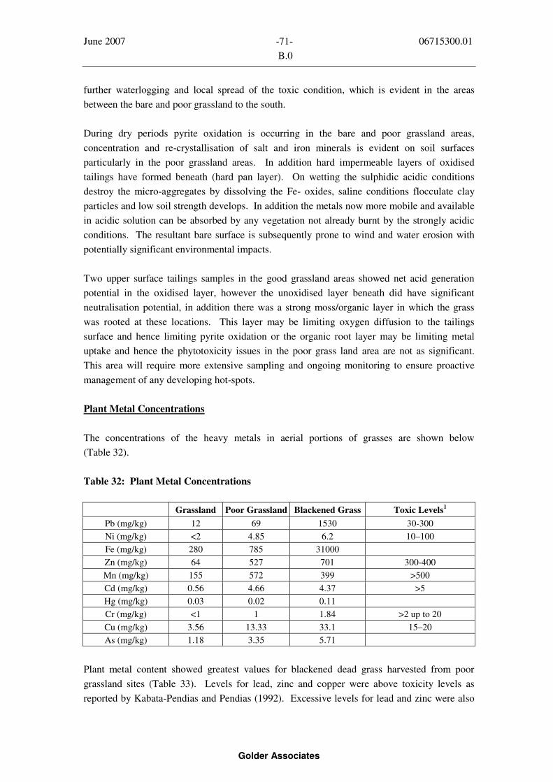
June 2007 -71- 06715300.01
B.0
Golder Associates
further waterlogging and local spread of the toxic condition, which is evident in the areas
between the bare and poor grassland to the south.
During dry periods pyrite oxidation is occurring in the bare and poor grassland areas,
concentration and re-crystallisation of salt and iron minerals is evident on soil surfaces
particularly in the poor grassland areas. In addition hard impermeable layers of oxidised
tailings have formed beneath (hard pan layer). On wetting the sulphidic acidic conditions
destroy the micro-aggregates by dissolving the Fe- oxides, saline conditions flocculate clay
particles and low soil strength develops. In addition the metals now more mobile and available
in acidic solution can be absorbed by any vegetation not already burnt by the strongly acidic
conditions. The resultant bare surface is subsequently prone to wind and water erosion with
potentially significant environmental impacts.
Two upper surface tailings samples in the good grassland areas showed net acid generation
potential in the oxidised layer, however the unoxidised layer beneath did have significant
neutralisation potential, in addition there was a strong moss/organic layer in which the grass
was rooted at these locations. This layer may be limiting oxygen diffusion to the tailings
surface and hence limiting pyrite oxidation or the organic root layer may be limiting metal
uptake and hence the phytotoxicity issues in the poor grass land area are not as significant.
This area will require more extensive sampling and ongoing monitoring to ensure proactive
management of any developing hot-spots.
Plant Metal Concentrations
The concentrations of the heavy metals in aerial portions of grasses are shown below
(Table 32).
Table 32: Plant Metal Concentrations
Grassland Poor Grassland Blackened Grass Toxic Levels1
Pb (mg/kg) 12 69 1530 30-300
Ni (mg/kg) <2 4.85 6.2 10–100
Fe (mg/kg) 280 785 31000
Zn (mg/kg) 64 527 701 300-400
Mn (mg/kg) 155 572 399 >500
Cd (mg/kg) 0.56 4.66 4.37 >5
Hg (mg/kg) 0.03 0.02 0.11
Cr (mg/kg) <1 1 1.84 >2 up to 20
Cu (mg/kg) 3.56 13.33 33.1 15–20
As (mg/kg) 1.18 3.35 5.71
Plant metal content showed greatest values for blackened dead grass harvested from poor
grassland sites (Table 33). Levels for lead, zinc and copper were above toxicity levels as
reported by Kabata-Pendias and Pendias (1992). Excessive levels for lead and zinc were also
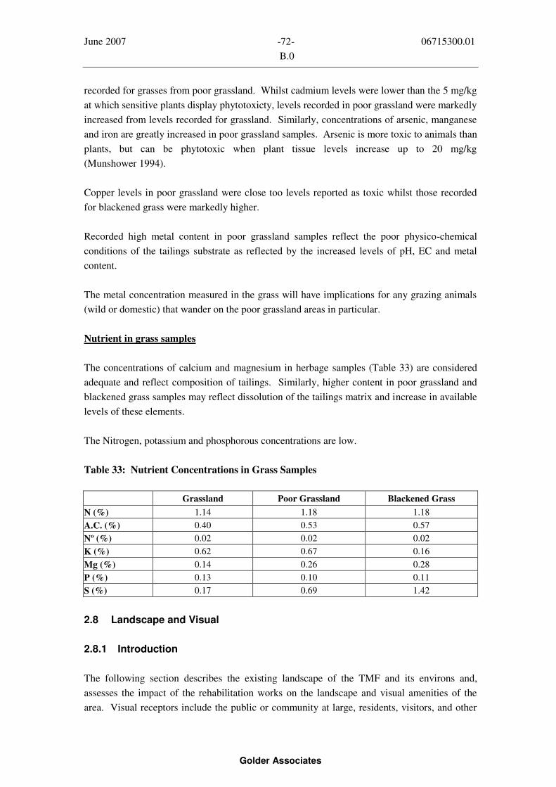
June 2007 -72- 06715300.01
B.0
Golder Associates
recorded for grasses from poor grassland. Whilst cadmium levels were lower than the 5 mg/kg
at which sensitive plants display phytotoxicty, levels recorded in poor grassland were markedly
increased from levels recorded for grassland. Similarly, concentrations of arsenic, manganese
and iron are greatly increased in poor grassland samples. Arsenic is more toxic to animals than
plants, but can be phytotoxic when plant tissue levels increase up to 20 mg/kg
(Munshower 1994).
Copper levels in poor grassland were close too levels reported as toxic whilst those recorded
for blackened grass were markedly higher.
Recorded high metal content in poor grassland samples reflect the poor physico-chemical
conditions of the tailings substrate as reflected by the increased levels of pH, EC and metal
content.
The metal concentration measured in the grass will have implications for any grazing animals
(wild or domestic) that wander on the poor grassland areas in particular.
Nutrient in grass samples
The concentrations of calcium and magnesium in herbage samples (Table 33) are considered
adequate and reflect composition of tailings. Similarly, higher content in poor grassland and
blackened grass samples may reflect dissolution of the tailings matrix and increase in available
levels of these elements.
The Nitrogen, potassium and phosphorous concentrations are low.
Table 33: Nutrient Concentrations in Grass Samples
Grassland Poor Grassland Blackened Grass
N (%) 1.14 1.18 1.18
A.C. (%) 0.40 0.53 0.57
Nº (%) 0.02 0.02 0.02
K (%) 0.62 0.67 0.16
Mg (%) 0.14 0.26 0.28
P (%) 0.13 0.10 0.11
S (%) 0.17 0.69 1.42
2.8 Landscape and Visual
2.8.1 Introduction
The following section describes the existing landscape of the TMF and its environs and,
assesses the impact of the rehabilitation works on the landscape and visual amenities of the
area. Visual receptors include the public or community at large, residents, visitors, and other

June 2007 -73- 06715300.01
B.0
Golder Associates
groups of viewers as well as the visual amenity of people affected. The impacts relate to the
changes in the visual amenity of the visual receptors.
The North Tipperary County Development Plan 2004-2010 states that the Council will
complete a County landscape character assessment (CLCA) which will subdivide the County
into landscape character types. This report has not been published to date. Key landscape aims
of the CLCA will include the following;
(a) to sustain, conserve and enhance the landscape diversity, character and quality of the
County;
(b) to protect sensitive areas from development that would detract from or be injurious to
the amenity of the area; and
(c) to provide for development and change that would benefit the rural economy while
protecting and enhancing the landscape.
2.8.2 Methodology
The landscape and visual impact assessment was prepared in accordance with good practice, as
described in the ‘Guidelines for Landscape and Visual Impact Assessment’, (GLVIA) by the
Landscape Institute with the Institute of Environmental Management and Assessment
(Second Edition, 2002). Reference was also made to the ‘Guidelines on the Information to be
contained in Environmental Impact Statements’ (EPA, 2002).
A clear distinction is drawn between impacts on landscape character and visual impacts, as
described below:
Landscape impacts relate to the effects of the proposals on the physical and other
characteristics of the landscape and its resulting character and quality; and
Visual impacts relate to the effects on the views from visual receptors (e.g. residents,
workers and tourists) and on the amenity experienced by these receptors.
The scope of the study is as follows:
To establish a baseline condition by describing the landscape of the Application Site
and the surrounding area;
To identify the impacts on the baseline condition during and following site
rehabilitation; and
To detail restoration landscaping recommendations

June 2007 -74- 06715300.01
B.0
Golder Associates
The assessment of visual effects takes account of the extent and prominence of the view
occupied by the site, the distance of viewpoints/arcs from the site, and whether specific
viewpoints would focus on the site due to proximity. Seasonal variations in vegetation cover
and the factor of distance whereby the degree of impact diminishes with increasing distance
from the site is also taken into account.
2.8.3 Existing Environment
2.8.3.1 Site Assessment
Information was gathered from a number of site visits in the latter half of 2006, one of which
included a detailed survey. The survey and analysis of the potential impacts of the
rehabilitation works on landscape and visual attributes examined the visibility of the
Application Site. A 5-km square box centred on the site is customarily used to roughly define
the zone within which the Application Site would be visible.
The survey was carried out in conditions of good light and clear visibility. Other sources of
information were consulted as follows:
Ordnance Survey mapping at 1:50,000 Sheets no.59;
Management and Rehabilitation of the Silver Mines Area Phase IV Report, Conceptual
Design, November 2005;
Flora and Fauna Survey of the Gortmore Tailings Management Facility, February
2007;
Vegetation Assessment for the Gortmore Tailings Management Facility, February
2007; and
NTCC County Development Plan 2004 – 2010
2.8.3.2 General Landscape Context
The Gortmore TMF is located c. 7km to the southwest of Nenagh and c. 4km to the west of
Silvermines Village Co. Tipperary. The landscape ranges from a generally flat, low lying
topography where the site lies, in the vicinity of the N7 and Kilmastulla River; to an upland
topography to the northwest (Arra Mountains) and southeast (Silvermines Mountains) of the
site. The lowlands are predominantly in pasture and field patterns are generally on a small
scale, defined primarily by high hedgerows and hedgerow trees. There are dispersed dwellings
and farmhouses along the roads in the area.
The following roads are in the vicinity of the Application Site;
The N7 national route is located c.1km to the northwest of the site;
The R499 is located c. 500m to the south of the site; and
June 2007 -75- 06715300.01
B.0
Golder Associates
There are also a number of third class roads including the road from Shallee crossroads
to Nenagh which runs to the southeast of the site, and a road from the N7 to the
northwestern corner of the site.
The Kilmastulla River runs along the eastern and southern sides of the site, and the Burgess
River runs along the western side of the site. The Dublin – Limerick railway line is located to
the southeast and its nearest point to the site is less than 500m away.
High sensitivity receptors are considered to be those residences within 500m of the site
boundary. Medium sensitivity receptors are the local road network and residences greater than
500m away from the site boundary.
2.8.3.3 Designations
There are no designations associated with the Application Site. The nearest protected view is
V13 (County Development Plan) described as “Views east and west of the R497 from the
R503 through the mountains to Dolla – including Mother Mountain to the West,
Knockacreggan to the East, Cooneen Hill to the East and the Silvermines to the west”. The
Silvermines Mountains to the west of this scenic view would block the view of the TMF. A
‘scenic viewpoint’ is located to the south of Silvermines village, with the TMF being clearly
visible from this location (Image 1, Appendix L).
Two candidate SAC’s occur in the Silvermines Mountains to the southeast of the site:
Silvermines Mountains West (site code 002258), located approximately 1km to the southeast
of the TMF, and Silvermine Mountains (site code 000939) which is situated approximately
5km from the site just 1km southeast of Silvermines village.
2.8.3.4 Gortmore TMF – Existing Landscape
The TMF covers an area of approximately 70 hectares which was first remediated by seeding
and fertilising works in September 1987. In terms of landscape character the TMF sits un-
naturally in the landscape and appears as a large engineered plateau in a surrounding valley
floor landscape which is predominantly used for grazing (Image 1, Appendix L).
Vegetation on the surface and sides of the TMF is patchy, with large areas of bare tailings
exposed (Image 2, 3, Appendix L), while other areas have some vegetation cover
(Image 4, Appendix L). These bare tailings are unsightly, being red in colour and highly
visible in relation to the surrounding landscape of pasture fields. There are strips of woodland
dominated by willows and alder around the southern and western sides of the site which act as
wind breaks on the most exposed sides of the TMF (Image 5, Appendix L). A line of poplars
has also been planted along the western boundary (Image 6, Appendix L). Wetland vegetation
dominates the northern and eastern sides of the site (Image 7, Appendix L).

June 2007 -76- 06715300.01
B.0
Golder Associates
As the TMF is a manmade elevated feature in lowland pasture it is highly visible from the
surrounding roads, dwellings and higher lands of the nearby mountains (Image 8, Appendix L).
Local site visibility is generally limited from the sparse number of nearby residential properties
surrounding the site. However, the lack of trees along the eastern and southern edges of the
site means the site is more visible from the roads and dwellings with views in this direction.
Landscape Quality
Landscape quality is assessed on the basis of a number of factors, including topography,
vegetation and built features. The combined quality of these factors is assessed using the
following scale, (Appendix M gives a more detailed description of the criteria used in
landscape quality evaluation):
Exceptional Landscape;
Highly Attractive Landscape;
Good Landscape;
Ordinary Landscape; and
Poor Landscape
The landscape quality of the study area has been assessed as Good Landscape (Category 3)
because the rural, well-vegetated countryside and surrounding upland areas form an attractive
setting. The surrounding landscape has a recognisable structure, with a pattern characteristic
of the region and, its mining history and heritage. However, there are some detracting features
(in addition to the TMF), such as a network of national and regional roads around the site. The
TMF itself has been assessed as Poor Landscape quality (Category 5) because of it’s dominant
and degrading nature in the landscape.
2.9 Human Health, Animal Health and Material Assets
2.9.1 Introduction
This section considers available information on public health/community, animal health and
material assets in the general vicinity of the site.
The World Health Organisation’s definition of health as ‘a state of complete physical, mental
and social well-being and not merely the absence of disease or infirmity’ serves to emphasis
the range of factors that influence health and is the definition adopted in this report.
Community is defined as those living and working in the vicinity of the site and the existing
services currently providing for the community. The section also looks at the general
“amenity” characteristics of the area within which the “community” exists.
June 2007 -77- 06715300.01
B.0
Golder Associates
2.9.2 Methodology
The methods used to examine the potential impacts of the proposed works included:
A summary of health effects associated with the Gortmore TMF based on information
contained in the IAG Study (DAFRD 2000) and the Silvermines Expert Group Study
(EPA 2004);
An assessment of site specific risk by assessing local factors and predictions for air,
water, noise etc.;
In making this assessment, the publication Health Impact Assessment: A Practical
Guidance Manual, published by the Institute of Public Health in Ireland, 2003 has
been referred to;
Examination of census data and other demographic data;
Examination of the NTCC County Development Plan and active planning applications;
and
Site visits and drive by surveys of residences, places of employment and local facilities
2.9.3 Existing Environment
The closest large centre of population to the proposed waste facility is Silvermines Village
(population 257, 2002 Census, details of the 2006 Census were not available at time of
writing). The immediate vicinity of the proposed site is rural in character, with isolated
residential dwellings located in the general vicinity (Figure 19). The site is situated c. 4 km
northwest of Silvermines Village and c. 2km southwest of the disused Mineral Processing
Facility at Garryard (old Mogul mine site).
The nearest dwelling is located c. 50m west of the NW corner of the TMF, with three other
dwellings located within a 500m radius (Figure 19).
There is no evidence that the persons who live in the area are any different from the
National Population in terms of average numbers per dwelling or for that matter general health.
From these figures it is estimated that somewhere between 8 and 24 persons live within 500m
of the TMF.
A school (Silvermines NS) is within about 4km of the site. The numbers of pupils at the school
is approximately 100.

June 2007 -78- 06715300.01
B.0
Golder Associates
The IAG investigation into the presence and influence of lead in the Silvermines area included
a human health investigation carried out by the Mid Western Health Board. This study aimed
to ascertain whether there was evidence of lead toxicity in the population of the area and to
recommend appropriate action. The study methods included measurement of blood lead
concentrations in whole blood samples from the population and the assessment of general
health of the population through a questionnaire based survey. The emphasis on blood testing
was on testing toddlers who are most sensitive to lead toxicity. The conclusion of the study
indicated that although high concentrations of lead had been found in the environment in the
area, these concentrations were not being transferred to the human population. The IAG study
also found that drinking water for human consumption was generally compliant with
Regulations and tests on milk and meat locally did not indicate cause for concern.
The IAG investigation into the presence and influence of lead in the Silvermines area also
included an animal health investigation carried out by the Veterinary Laboratory Services of
the DAFRD. The objectives of that study were to quantify the uptake of environmental lead by
cattle in the Silvermines area and to determine its significance in relation to animal health. The
decision to restrict the investigation to cattle was made on the grounds that cattle were the
predominant food producing animal in the area and are also more susceptible to the toxic
effects of lead than sheep. The conclusions of that study indicated no evidence of widespread
problems of lead toxicity in animals in the Silvermines area. Outbreaks of lead poisoning were
limited to two farms in an area with the highest environmental concentrations of lead, which
were unlikely to have been caused by dust blows from the TMF. Other farms did have raised
lead levels and associated risks, which would persist until control measures were implemented.
Subsequent to the publication of the IAG report, various public awareness campaigns were
undertaken to advise the local community on practices to minimise their potential exposure to
lead and dust in the environment, and to provide guidance on better management of animal
health.
In addition, the recommendations included the formulation of management and rehabilitation
plans for the TMF to minimise any future impacts from the facility.
The NTCC County Development Plan (2004-2010) specifically addresses the Silvermines area
in Section 4.6.1a. The plan recognises the long history of mining in Silvermines and the
resultant complex legal and technical issues in the rehabilitation and long term management of
identified sites in the area. The recommendations of the IAG Report in the Investigation into
the Presence and Influence of Lead in the Silvermines Area of County Tipperary are supported
and the Plan recommends that they are taken into account for any future development in the
area.
June 2007 -79- 06715300.01
B.0
Golder Associates
2.10 Traffic
2.10.1 Introduction
The proposed Gortmore rehabilitation project will involve the transport of capping materials to
the TMF site; the majority of which is required to be placed on the west side of the site. Post
rehabilitation there is not expected to be any significant traffic associated with facility.
The time scale for the works may be restricted by surface conditions on top of the TMF which
will be dependent on prevailing weather conditions.
The TMF site is potentially accessible from both the North and South. The preferred entrance
to the site will depend on the phasing of the remediation works, source of materials, weather
conditions and traffic constraints.
2.10.2 Methodology
Possible routes for which potential traffic impacts may occur on are shown in Figure 20.
These routes allow for access from both the north and south of the TMF. Available traffic data
for the area was also reviewed.
2.10.3 Existing Environment
Access to the north-western side of the TMF from Shallee Cross is via the R499 turning right
onto the N7 at the “Silvermines” junction, proceeding north for some 2 km and turning right
off the N7 at Ballywilliam (traffic island opposite the Texaco filling Station). The TMF is
approximately 1km south of the N7.
Access to the South side of the TMF from Shallee Crossroads is via the Capparoe Road,
turning left onto the Gortmore access roadway beside the disused line to the old Mogul mine
site. This route crosses the Iarnrod Eireann, Nenagh to Limerick rail line and continues for
approximately 0.8 km on a gravel roadway before crossing the Kilmastulla River to reach the
site. The total length of access road from the public road is c. 0.9km.
Previous traffic surveys on the R499 (Waste Management Ireland, 1998) involving ten hour
traffic counts found that traffic in the area consists primarily of local journeys with peaks early
in the morning (09.00-10.00hrs) and again in the evening (16.00-18.00hrs). Some 80% of
traffic was cars, while HGVs account for about 5-6%. In recent months traffic counts were not
undertaken because extensive roadworks on the N7 have resulted in significant traffic volumes
being diverted at Toomevara going south, and traffic being diverted north at the Silvermines
N7 Junction, resulting in all diverted traffic travelling through Shallee Cross Roads and along
the R499. This has resulted in continuous uncharacteristic heavy traffic volumes on the R499.

June 2007 -80- 06715300.01
B.0
Golder Associates
2.11 Summary Existing Environment
2.11.1 Assessment of Surface Vegetation
The existing vegetation conditions on the surface of the TMF including the associated tailings
geochemistry was presented in detail earlier in Section 2. The existing good grassland consists
of good cover dominated by Agrostis and Festuca, which have low nutrient demand and are
currently self sustaining. It is recommended that the areas of good grassland and gorse be
subject to performance monitoring regularly and management as required. The facility as a
whole will be monitored during construction, post construction and in the long-term, allowing
smaller areas which may develop in the existing good grass areas to be remediated as required.
Any developing hot-spots will be managed by placing a mixture of limestone dust and organic
materials over the affected areas and seeded with suitable grasses.
In summary it was found that:
Areas of bare tailings were characterised by low pH, high EC, high sulphate and high
metal content. Exposed tailings had higher pH and EC values than subsurface samples;
Vegetation samples from good grass areas did not display signs of metal toxicity.
Vegetation samples from poor grassland areas showed elevated concentrations of all
metals and in some cases these were above recommended toxicity levels;
Tailings samples from the bare and poor grassland areas indicated potential to generate
acidity. Tailings samples taken from good grassland had the greatest neutralization
potential;
It appears that upward movement of acidity and potentially phytotoxic metal salts have
severely impacted on vegetation sustainability in the poor grassland areas; and
It is proposed based on the results of the work undertaken that rehabilitation work
already proposed for the bare areas (c.12ha approximately) be extended to the poor
grassland areas (c.8.5ha approximately) based on the vegetation toxicity levels and the
associated acid generating potential of the tailings in these areas which make long term
vegetation sustainability unlikely (Figure 21). It is also proposed that rehabilitation be
undertaken over specific areas along the upper and lower slopes of the TMF.
2.11.2 Surface Water and Ground Water Quality
Existing surface water and groundwater quality was presented in detail earlier in Section 2, in
summary it was found that:

June 2007 -81- 06715300.01
B.0
Golder Associates
Results from groundwater analysis for samples taken from recently drilled holes
(2006) and from previously drilled holes (2001) show similar values for metals and
sulphate concentrations. This is not unexpected as the boreholes were drilled on the
tailings dam surface (2006 only) and close to the toe of the dam wall (2001 & 2006).
Previous studies of groundwater undertaken in the Silvermines area have found no
evidence of groundwater contamination at any potential receptor;
It is recommended that long-term monitoring be incorporated into the design for the
TMF to monitor for any potential surface water and groundwater contamination from
the TMF site;
The volunteer wetlands around the perimeter of the TMF are removing suspended
solids and some metals from the surface water and seepages emanating from the TMF.
It is proposed that monitoring of the water quality of the runoff from the new cap be
undertaken initially for a 3 year period, with future monitoring being incorporated into
the long term monitoring plan for the TMF;
There are numerous uncontrolled seepages direct to the river from the volunteer
wetlands. These seepages will be channelled into the refurbished wetlands via a series
of perimeter toe drains;
The Settlement Ponds to the east of the tailings pond are not functioning effectively
and will be refurbished to provide additional wetland capacity; and
Biological water quality monitoring in the adjacent Kilmastulla River indicated no
significant change in recent years with a Q rating of 3-4.

June 2007 -82- 06715300.01
B.0
Golder Associates

June 2007 -83- 06715300.01
B.0
Golder Associates
3.0 DESCRIPTION OF PROPOSED WORKS
3.1 Conceptual Plan for Rehabilitation Works at Gortmore TMF
SRK’s Phase IV report (pages 38 to 42 and Figure 10.1) described the recommended
conceptual design for the remedial and management works at the Gortmore TMF, as agreed by
all stakeholders. The proposed works described in Figure 10.1 of the Phase IV Report are as
follows:
A. Growth medium to be placed on areas of poor vegetation, existing windbreak shrubs to
be extended (Areas to be revegetated to be determined);
B. Plant tree screen at toe;
C. Improve existing sediment traps at toe and repair of gulleys;
D. Construct a new decant weir and discharge pipeline from tailings pool; and
E. Carry out remedial repairs to Retention Ponds (Settlement Ponds) and optimise
wetland operations.
3.2 Overview Description of Proposed Works Subject to Planning Approval
The Conceptual Design has been reviewed by Golder and the details of the works now
proposed are described briefly below and in more detail later in Sections 3.5 to 3.11.
Section 3.3 discusses Golder’s key considerations in the design of the proposed works.
The general nature of the works now proposed in connection with the remediation and
rehabilitation of the Gortmore TMF are as follows:
Importation, storage and placement of engineering materials to cap bare tailings
surfaces and areas of poor vegetation;
Importation, storage and placement of engineering materials to buttress or cover
embankment side slopes;
Earthworks, comprising cut and fill operations, to renovate and enhance the
performance of the existing wetlands;
Ancillary civil engineering drainage works, including excavating and lining channels,
ponds and wetland areas, installing piping systems and constructing concrete
appurtenances associated with the drainage works;
Ancillary ground preparation and haul road construction;
Earthworks, including cut and fill, to allow landscaping of the perimeter of the TMF;
Landscaping including planting shrubs, trees and the like and spreading grass seed;
Surface water and groundwater monitoring; and
On-going monitoring and management of the facility.
Aerials photographs of the site are presented in Figures 2, 3 and 17. The extent of the site
showing original dam wall features is shown on Figure 22.

June 2007 -84- 06715300.01
B.0
Golder Associates
3.3 Design Considerations
3.3.1 General Considerations
A pragmatic approach has been taken in dealing with the adaptation of the Conceptual Design
to produce an optimum design solution for Gortmore, based on its unique site specific
conditions, with mitigation measures targeted at reduction of particular risks. The most
important element of the rehabilitation of Gortmore is the capping system. Hence, the focus of
the design work has been the capping and drainage of the surface of the TMF. The complexity
of any capping system is a function of the degree of risk posed by the contaminated media and
may vary from a simple soil cover to multi-layered systems. Thus, the appropriateness of any
one or more of the possible capping components will depend on the agreed objectives in terms
of environmental protection, safety, timescales and costs, for example.
Ultimately, the design attempts to eliminate, or minimise, the pollution linkages between
hazard sources (i.e. the tailings and associated leachate) and potential receptors.
At Gortmore the potential receptors, and potentially significant environmental risks and
effects, identified by SRK and confirmed by Golder as follows:
Air – risk of dust blows from bare tailings;
Landscape & Visual – area highly visible in landscape;
Human beings – dust blows, visual impact, health and safety, water toxicity;
Livestock – toxicity due to dust on agricultural land & metal-contaminated surface and
groundwater;
Flora & Fauna – degraded habitat, herbage toxicity and poor plant growth, risk of
wildlife toxicity (terrestrial and freshwater); and
Water – leaching of metals into groundwater and into surface waters.
The key overall objective for the rehabilitation works at Gortmore is to ensure stability of a
self-sustaining vegetation cover to prevent dust blowing from the top surface or the edges of
the TMF. The chosen Conceptual Design involves selective placement of a growth medium
and re-vegetation, establishment of vegetation screen and minor remedial earthworks,
including ancillary engineering relating to surface water drainage, and associated wetlands.
The SRK Phase II study (SRK, 2002) included a risk-based approach to identify the key issues
and to develop priority targets to gain optimum benefit from the proposed remediation
schemes. Local stakeholder participation was a very important aspect of this assessment.
The Conceptual Design solution for the capping of Gortmore is 75mm of crushed limestone
chippings overlain by 75mm of a soil (growth-medium) that is subsequently vegetated over an
area of approximately 12ha.

June 2007 -85- 06715300.01
B.0
Golder Associates
For the purposes of selecting the most appropriate final design of the capping system and other
ancillary works on around the perimeter of the TMF, Golder took into account a number of
factors:
Climate and hydrology;
Hydrogeology;
Groundwater quality and surface water quality in the receiving water course,
the Kilmastulla River;
Vegetation surveys;
Performance of Wetlands;
Availability and proximity of capping materials; and
Trafficability of surface and practicality of placement of layers
3.3.2 Climate and Hydrology
The climate of the area in particular, rainfall/precipitation, evapotranspiration, evaporation, and
wind direction were the key factors considered in the design of the rehabilitation works.
Climate is discussed in more detail in Section 2.1.
The climate and hydrology of the area indicate that there will be evapotranspiration from the
TMF surface and a net available rainfall will infiltrate the cap of the TMF and/or will occur as
runoff. The rate of infiltration can be reduced by differing degrees by sloping the surface to
drainage channels and/or pools, providing a granular drainage layer in the cap and developing
a good vegetative cover to maximise evapotranspiration.
Two potential cap scenarios were modelled by hydrologists in the Denver office of Golder
Associates Inc using the Hydrologic Evaluation of Landfill Performance (HELP) models. The
model runs related to the Conceptual Design capping system comprising 75mm of crushed
limestone overlain by 75mm ‘topsoil’ and the capping system comprising 300mm (average) of
rockfill overlain by 200mm (minimum) of ‘topsoil’ The results of the modelling exercises are
presented in Appendix N. The results of the modelling show the benefits of thicker layers in
terms of minimising the potential for the upper growth medium layer to dry out, ensuring the
effectiveness of the capillary break layer, increasing evapotranspiration from the surface and
reducing infiltration into the tailings.
3.3.3 Hydrogeology
The local hydrogeology and the original design of the TMF, together with general experience,
site observations and technical assessments suggests that there will be continued seepage and
runoff of ARD from the facility, and hence the existing engineered perimeter seepage
collection and treatment system should be updated and refurbished. The location of the
observed seepages from the TMF are shown on Figure 23.

June 2007 -86- 06715300.01
B.0
Golder Associates
3.3.4 Water Quality
The quality of groundwater in the underlying limestone bedrock immediately adjacent to the
TMF (based on data from a number of boreholes) has been shown to be affected by the TMF.
This is not unexpected for a facility that is unlined. However, a groundwater risk assessment
carried out by SRK in 2002 concluded that there is a low risk to down-stream receptors from
potential groundwater discharges from the TMF.
There is no evidence of any significant impact on potential groundwater receptors in the
Silvermines area. In addition, the proposed remediation works are expected to improve both
surface water, groundwater and stream sediment quality in the area of the TMF. The risk
assessment (previously carried out) and groundwater sampling showed that the concentrations
of potential pollutants modeled in the study were likely to be so low as to pose little or no
threat to the downstream receptors. This was considered to be due to a combination of factors
including high retardation coefficients of the contaminants, the Cation Exchange Capacity
(CEC) of the alluvium underlying the tailings facilities and dilution within the underlying
bedrock.
Significantly, the long term management plan for the TMF will include monitoring of
groundwater quality at the current monitoring boreholes and water supplies in the vicinity of
the TMF to allow ongoing assessment of any risk to downstream receptors. If there are signs
of deterioration in groundwater quality, an action plan will be developed and implemented as
required.
The Kilmastulla River is the ultimate receptor of surface water and some groundwater
discharges from the TMF. There is significant dilution potential in the Kilmastulla River for
the discharges from the TMF. The quality of surface waters discharging from the TMF into
the Kilmastulla River generally meets with water quality criteria (EC Quality of Salmonid
Waters Regulations - S.I. 293 of 1988 and EC Quality of Surface Water Intended for
Abstraction of Drinking Water Regulations - S.I. 294 of 1989), except for Zn and sulphate at
the point of discharge. There are a number of uncontrolled seeps currently coming from the
TMF, which would be controlled by the proposed re-design and remediation of the drainage
and wetland system. It is noted that the water quality of the Kilmastulla River down stream at
Cranna Bridge meets the EC Quality of Salmonid Waters Regulations (S.I. 293 of 1988) and
EC Quality of Surface Water Intended for Abstraction of Drinking Water Regulations (S.I. 294
of 1989).
3.3.5 Vegetation Surveys
The quality of vegetation cover and its sustainability are both crucial factors in the
determination of areas requiring rehabilitation. Vegetation surveys and associated sampling
have shown that there is a large area of poor vegetation cover that is failing or likely to fail in
the future, and is therefore not likely to be sustainable over time. The findings from these

June 2007 -87- 06715300.01
B.0
Golder Associates
investigations have had a very significant effect on the estimated surface area of the TMF
requiring rehabilitation, i.e. this has now increased from about 12ha to about 24.5ha.,
(Figure 21).
3.3.6 Performance of Settlement Ponds and Wetlands
Based on assessments by Golder, it has been determined that the existing c.1.5m deep
Settlement Ponds, located at the north-east corner of the site, are not currently serving a useful
function in relation to the treatment of the discharges from the TMF surface. These ponds
need to be refurbished to provide additional wetland capacity. There are breaches in the
wetland side wall containment that allow short circuiting of the wetlands and direct discharge
of effluent into the Kilmastulla River. Along the north-east sector there are numerous seeps
along the toe of the dam that flow across the gravel haul road. Works are required to capture
these seeps within the enhanced wetland system.
3.3.7 Availability and Proximity of Capping Materials
In general terms, there are a number of known materials in the area that may be suitable for
capping the TMF. The suitability of these is determined in terms of their (i) acid generation
potential, (ii) proximity to the site, (iii) availability, (iv) chemical composition and (v) costs.
Available capping materials include a practically unlimited supply of crushed rock from the
Magcobar stockpiles. Tests on materials from Magcobar Dumps A and B for ARD potential,
and on two other sources of crushed rock (from commercial quarries), indicate that some of the
materials sampled from Magcobar have the potential for acid generation, whereas the samples
from the commercial quarries do not. Any materials used will be subject to quality control
procedures.
There are (conservatively) about 12,000m3
of river dredgings located on the TMF site along
the banks of the Kilmastulla River (Figure 23). The dredgings have been used in the past to
dress the exposed tailings on the upper slopes of the dam wall with some success. Some of the
dredgings contain relatively high available metal concentrations and will need to undergo a
strict quality control procedure prior to emplacement if they are to be used as part of the
capping solution.
The adjacent M7 motorway construction will produce a quantity of a suitable topsoil and peat,
and should it become available that could be considered for use to form the growth medium
layer in the construction of the capping system and other works on the site.
3.3.8 Trafficability of Surface and Practicality of Placement of Layers
The boreholes and site observations have established that within the TMF there is a thin crust
of oxidized tailings overlying very soft grey unoxidized tailings. The crust thickness varies

June 2007 -88- 06715300.01
B.0
Golder Associates
from 100mm in the centre to in excess of 1000mm (1m) at the edges. The grading of the
tailings varies from location to location as does the strength. Site experience and observations
have revealed that this material has a very low bearing capacity and is not capable of carrying
conventional plant. The strength of theses fine grained materials are strongly influence by
their moisture content and the strength reduces significantly during the wet winter months.
Recent construction (in September 2006) of vegetation trial plots has illustrated how sensitive
the tailings are to disturbance and the need to have low ground pressure equipment, geotextiles
and geogrids used in the construction of the capping system.
Restoration of tailings ponds involves some unique engineering challenges. When pumping of
tailings ceased substantial areas of the surface of the tailings, such as the ‘beach’ areas near the
inlets, become dry under the influence of a combination of evaporation and gravity drainage.
However, because of the fine-grained nature of most of the deposits, drainage of the bulk of the
tailings rarely proceeds to completion, even under arid climate conditions. Very fine tailings
therefore tend to remain very wet and very weak almost indefinitely. If the surface water is
removed or evaporates in periods of dry weather a surface crust forms due to desiccation.
However the thickness of the crust will be limited because as drying occurs shrinkage of the
surface layer leads to significant fissuring which breaks the capillary column which initially
pulls water to the top of the deposits. Subsequently the presence of the overlying dry crust
largely prevents further drying by evaporation, with the tailings below remaining very wet as
evident at Gortmore.
An appropriate specification of works for initial capping of a tailings dam calls for an
operation which is contrary to all the instincts of uninitiated plant operators: the creation of
single layer of around 1m in thickness, spread in a very gentle and progressive manner. In
contrast most plant operators will be used to working a layer thickness of two or three metres,
bulldozing uphill towards a ridge at the advancing face, dumping incoming spoil as close to the
advancing face as possible, and commencing the laying-out of the second and even third layers
close behind the initial advancing face. Over tailings, this normal operational approach can
quickly lead to large out-of-balance loadings in the underlying deposits, with potentially
serious consequences for construction personnel and the overall stability of the tailings deposit.
To ensure its satisfactory implementation will demand close management by a well-trained and
highly experienced resident engineer. They will need to ensure that no earthmoving equipment
be allowed onto the surface of the tailings without prior authorisation, and that no dumping of
material be allowed on the surface of the tailings unless specifically approved by the Engineer.
In areas of the deposit surface close to the inlets and anywhere the materials are coarse and
therefore well drained, the placing of a capping layer is likely to be relatively straight forward.
It is crucial to achieve completion of the initial covering layer without significant heave.
Heave may be induced in this layer if the initial advancing layer is too thick, the spreading
plant is too heavy and /or heavily-loaded earthmoving plant is allowed to run on the capping
layer. The aim is to install the capping layer in such a manner that overloaded bearing capacity
failure is provided and any excess porewater pressures generated by the loading imposed by
the capping material is dissipated so that adequate strength is maintained in the tailings.

June 2007 -89- 06715300.01
B.0
Golder Associates
Unlike conventional earthworks contracts where contractors are seeking to optimise their plant
to achieve maximum earthmoving in the minimum time, in placement of materials on tailings
it is usually a case of ‘more haste, less speed’. The rate of placing must be determined by
consideration of the condition of the tailings deposits NOT plant availability and efficiency.
Golder have considerable experience of trafficking on similar tailings at Tara Mines and
elsewhere. Golder designed and constructed an 8m high dam wall on the surface of tailings at
Tara to increase the storage capacity of the facility between 1998 and 2006. To place the clay
materials forming the bulk of the dam wall, a 1m thick layer of rockfill was placed over the
dam footprint and on top of a geotextile placed on the surface of the tailings. The rockfill was
required to allow access to the tailings for the earthmoving equipment and to act as a surcharge
to remove the initial deformation of the near surface soft tailings. The rockfill was removed
after several months using an excavator and the settlement observed was up to 500mm. The
clay fill was then placed once the rockfill was removed and the first lift was placed at a
thickness of 750mm.
At the TMF at Aznacollar, near Seville Spain, Golder designed a rockfill platform. The
thickness of the rockfill platform varied based on the consolidation characteristics of the
underlying tailings, as well as the need to profile the cap to collect surface runoff water.
Generally, a minimum of 1m of rockfill was required for trafficking purposes. In places where
the tailings were particularly soft, geotextiles were placed directly onto the tailings to increase
its supporting capacity. This helped to reduce the thickness of rockfill required.
At the Les Terrains Auriferes site, Golder designed and oversaw the placement of a 500mm
rockfill layer on tailings in northern Quebec, Canada.
At the Lacnor site, Elliot Lake, Ontario, Canada, a 300mm thick (capillary breaker layer) of
non-acid generating blast rock was placed on c. 16ha of tailings surface. A growth medium
layer of 150mm thickness was successfully placed and revegetated.
The following photographs demonstrate the condition of the site before and after rehabilitation.
Before Rehabilitation After Rehabilitation

June 2007 -90- 06715300.01
B.0
Golder Associates
3.3.9 Geotechnical Considerations
Previous investigations have established that the outer slopes of the dam have an adequate
factor of safety against failure (SKR 2002a: Boland, 1999).
The construction of the dam wall was described in Boland, 1999 and Arthurs 1994. According
to surveys by Golder, the height of the walls varies from 6.7m to 8.7m and the outer slope
varies from 1(V) : 2.2(H) to 1(V) : 1.1(H). Figures 24 and 25 show cross-sections through the
dam walls.
Section 3.4 addresses the slope stability analysis carried out by Golder.
3.4 Stability of the Dam Walls
3.4.1 General
The side slopes at Gortmore appear to be constructed of imported granular fill for much of the
length although in some areas as shown on Figure 23, tailings are exposed on the downstream
dam wall. It is not known whether the tailings are covering the rockfill as a consequence of a
spillage in the past or were left exposed after the dam wall was raised and not covered with
rockfill protection material. The design schematic profiles (Boland, 1999) of the dam walls are
shown in Appendix O and indicate some variation depending on the tailings cells they
enclosed. The three ponds (cells) constructed to form the Gortmore facility are shown in
Figure 22 named ponds (cells) 1, 2 and 3, and in Appendix O. The locations of the majority of
the schematic profiles are not known. From the profile sections, the starter dam was
constructed from ‘boulder’ clay for pond 1 (Boland, 1999) and from rockfill with an upstream
clay barrier for ponds 2 and 3 (Boland, 1999). The facility was raised during the life of the
mine operation using tailings by the upstream method of construction. The tailings exposed on
the sides were covered with rockfill. The sides of the final lift of the facility constructed with
tailings have not been covered with rockfill. The rockfill cover, based on the sketches, is a
minimum of about 2.3m thick. However, visual observations suggest that the rockfill could be
less than this and this could explain the exposed tailings.
The quality of the rockfill is variable from boulder size limestone rock fragments to a well
graded silty sandy gravel and cobble size argillaceous limestone fragments. The argillaceous
limestone shows signs of weathering which has resulted in minor superficial sloughing of the
material on the side slopes.
The height of the dam wall is generally 6.5m, with a maximum height of 8.7m. The
topographical survey of the dam wall indicates relatively steep-sided slopes between 1V:1.1H
and 1V:2.2H. These are indicated on Figure 26. Groundwater levels measured in the
piezometers installed through the surface of tailings indicated an average value of 3.5 mBGL,
with a minimum of 1.4 mBGL for shallow piezometers and a maximum of 8.8 mBGL for deep

June 2007 -91- 06715300.01
B.0
Golder Associates
piezometers. Measurements of the piezometers installed at the downstream toe of the dam
wall indicate an average value of 1.4 mBGL, with a minimum of 0 mBGL and a maximum of
3.3 mBGL.
Observations on site indicate that slopes are generally stable except for minor superficial
sloughing. However, Golder consider for long term dam stability (requiring some degree of
maintenance), the slope gradient should not be steeper than 1V:1.5H. To minimise
maintenance, all side slopes should be less than a slope gradient of 1V:2H.
3.4.2 Stability Analysis
The slope stability analysis was based on the worst possible scenario for a given profile, using
the steeper side slopes measured in the field and takes into account the construction of the cap
to be placed on top of the facility. The following factor of safety values were obtained from
the analysis:
Slope Gradient Factor of Safety
1:1.1 1.0
1:1.2 1.0
1:1.3 1.1
1:1.4 1.1
1:1.5 1.3
The slope stability analysis was undertaken using Slope W V6.11 (Geo Slope International
Ltd, 2004) and the plots are given in Appendix O.
To improve the factor of safety, a thin waste rock buttress has been added at the toe of the dam
wall. The buttress increases the restoring force at the toe of the dam wall which decreases the
overall slope gradient and increases the factors of safety as indicated below.
Initial Slope Gradient Final General Slope Factor of Safety
1:1.1 1:1.6 1.3
1:1.2 1:1.6 1.3
1:1.3 1:1.6 1.3
1:1.4 1:1.6 1.3

June 2007 -92- 06715300.01
B.0
Golder Associates
As indicated above, the factor of safety can be increased to 1.3 by the construction of a buttress
thereby reducing the dam slope.
3.4.3 Buttress
The lateral extent of the buttresses are presented in Figure 26 and are discussed below.
Construction of a 130m long rockfill buttress, 3m high, 2m wide on top and 3.5m wide
at the base, at a slope of 1V:1.5H where the current slope is 1V:1.1H slopes between
chainage 1350m and 1480m;
Construction of a total of 1000 m long rockfill buttress, 3m high, 2 m wide on top and
3 m wide at the base, at a slope of 1V:1.5H where the current slopes are 1V:1.2H and
1V:1.3H between chainages 60m and 370m, between chainages 450m and 650m,
between chainages 750m and 950m, between chainages 1040m and 1150m, between
chainages 1250m and 1350m, and between chainages 2090m and 2170m;
Construction of a total of 200 m long rockfill buttress, 3m high, 1 m wide on top and
1.5 m wide at the base, at a slope of 1V:1.5H where the current slope is 1V:1.4H
between chainages 1740m and 1860m and between chainages 2170m and 2250m.
The rockfill that will be used in the buttress will be good quality non acid generating crushed
rock with little argillaceous material.
Woodland scrub around the base of the TMF will be retained where possible during
construction works.
3.4.4 Buttress Construction
The buttresses can be constructed from the top of the slope or from the base of the slope
although ideally it would be preferable to have access from both localities. The existing
vegetation at the toe and on the slope of the dam wall would be removed, mulched and used as
an addition to the growth-medium for the cap. The surface of the exposed toe and slope would
be inspected prior to placement of the rockfill. The slopes would be dressed with an excavator
to remove any loose material. The loose material would be reused in the buttress. The rockfill
will be placed by an excavator and nominally compacted. End tipping from the top of the
slope would not be acceptable due to the possibility of segregation of the rockfill. Where
necessary, the perimeter toe drain will be moved to accommodate the buttress.
It will be difficult to vegetate the rockfill covering the dam walls unless the slopes are regraded
to 1V:2H, as it will be difficult to maintain a growth medium on steeper slopes.

June 2007 -93- 06715300.01
B.0
Golder Associates
3.5 Detailed Description of Proposed Preparatory Works
This section of the report addresses proposed works to allow access of lorries carrying
engineering materials to the TMF from the north and south.
3.5.1 Access to Gortmore – Southern Route
The southern route is via the existing road established by the original operator, “Mogul”. This
route leaves the Shallee to Nenagh local road (No. L 2142) and crosses the Iarnród Eireann
(IE), Limerick to Nenagh line and continues a further 0.8 km to reach the tailings dam after
crossing the Kilmastulla River via a bridge. The total length of the existing access road from
the public road to the bridge is c. 0.9 km.
3.5.1.1 Roadway
The access roadway from the pubic road is in poor condition. The road will be reinforced and
drainage will be improved where necessary along its length. Existing passing bays will be
rehabilitated along this route to facilitate passing two way traffic.
3.5.1.2 Rail Crossing
Iarnród Eireann (IE) has stated to NTCC (1/02/2007) that the crossing will require
strengthening and manning by IE staff during use as a haulage road whilst capping works are
being carried out at Gortmore. These works will be carried out as required by IE.
3.5.1.3 Kilmastulla Bridge
The bridge consists of 4 steel joists carrying two timber decks. The main beams appear in fair
condition. An analysis of their load bearing capacity estimates each beam can carry
150 kN (15.2 t) at the original span of 9.8m.
The timber decking is made from ex-railway sleepers of indeterminate age and will be
replaced.
The abutments on either side of the riverbank consist of stone ballast supporting a timber deck
over which is lain two 10” x 8” (254 x 203) U.B. set 29” (0.740mm) apart. On these four
beams (two on each bank) rest the 4 joists that makeup the bridge. The river has undercut each
side. Gabions or similar strengthening measures will be installed to reinforce the existing
abutments.
As an alternative to refurbishing the existing bridge structure, consideration will also be given
to the installation of two concrete box culverts, 2m by 2m covered with rockfill to form a

June 2007 -94- 06715300.01
B.0
Golder Associates
suitable surface. The final decision will be based on the Contractors tender price for
undertaking the two options.
3.5.2 Access Roads Across Tailings from East to West
An internal dam wall between Ponds 1 and Ponds 2/3 (See Figure 22) will be used as a
foundation for an access road wide enough to accommodate two-way traffic across the tailings
surface (at least 8m wide at road surface level). A geogrid will be laid as required on the
tailings surface followed by crushed rockfill to at least a thickness of 1.0m. This road will
extend from the outer dam wall (at the east) to the separating wall between Ponds 2 and 3. The
material placed in this road could be used later to cap the surface on the eastern side of
the TMF.
3.5.3 Access to Gortmore – Northern Route
3.5.3.1 Roadway and Entrance
Access to the northern side of the TMF is from the N7 at Ballywilliam (i.e. at the traffic island
opposite the Texaco filling station). The Gortmore TMF site is approximately 1km south of
the N7. This road is single lane with two existing passing places exist and a third will be
sought at the new N7 site crossing which is approximately 500m north of the Gortmore site. A
new entrance will be provided onto the site at the north-west corner, this is shown in Figure 27.
3.6 Detailed Description of Proposed Capping System and Materials
3.6.1 Capping Layers
Vegetation beds constructed on Gortmore during September 2006 have shown that without a
separator geotextile the growth-medium tends to filter down into the stone cap, thus allowing
acidic water to be drawn up into the growth-medium, by capillary action and so negating the
benefit of the cap. Experience at Tara Mines and elsewhere has shown that geo-synthetic
layers will also be required to minimise the loss of stone into underlying soft tailings and
prevent tailings migrating upwards as a result of the dissipation of excess pore pressure.
The principal elements of the proposed capping system on the surface of the TMF are as
follows:
Geosynthetic layer;
300mm layer (average) of granular non-acid generating crushed stone (rockfill);
Geosynthetic layer; and
200mm layer (minimum) of growth medium, together with a suitable seeding mix.
A lower geotextile/geogrid will be used to avoid loss of rockfill into the tailings and to provide
ground support for traffic carrying and/or spreading rockfill onto the tailing surface. A

June 2007 -95- 06715300.01
B.0
Golder Associates
geotextile will also be placed on the surface of granular layer to act as a separating layer to
avoid loss of the growth medium into the rockfill. The granular rockfill will act as a capillary
layer, and the 300mm thickness is to facilitate drainage and minimise risks of ponding on the
surface and contaminant capillary rise which could ultimately compromise the growth-medium
and vegetative layer. Further, it is Golder’s experience that 300mm is the average thickness
that can be placed and spread using appropriate equipment without disturbing the underlying
tailings (or geotextile). Thus, the total thickness of this capping system is 500mm (min).
The other key difference between the Golder design and the Conceptual Design relates to the
area of the TMF that needs capping. Golder’s surveys have shown that the area for capping
has increased from c.12ha to c.23ha (excluding the lower side slopes) if effective long term
dust control is to be achieved.
The crushed stone will be placed on either a (i) geogrid-geocomposite in the areas where haul
roads will be constructed out onto the tailings surface or (ii) a heavy geotextile in the
remaining areas to be covered. It is estimated that geogrid-geocomposite will be laid over
c.30% of the tailings surface where haul roads will be constructed and the heavy geotextile will
be laid over the remainder c.70% of the tailings surface.
On to the crest of the dam walls, the proposed design details are different. In detail there will
be three types of capping in different zones of the TMF as shown on Figure 21 and described
below.
Type I Cap
This capping type will be used over large areas of the TMF. It will include geosynthetic
layers, a rockfill capillary break layer 300mm thick on average and growth medium layer
minimum 200mm thick. Golder has identified a total area for Type I capping on the surface of
the TMF of about 20.5 ha. This includes bare tailings, poor grassland and a narrow transition
zone from those areas onto the good grassland. The Zones are outlined on Figure 21 and are
labelled A to D.
The capping layers on these areas will be tapered or feathered out across the existing uncapped
surface over a distance of about 2 to 4m (Figure 28a) from the edges. In some areas the
existing gorse will need to be removed to allow access and/or placement of the cap. The extent
of gorse removal will be kept to a minimum.
On edges of the cap, where it tapers out on the existing good areas of grassland, either a French
contour drain will be constructed or the rockfill layer will be left exposed to allow drainage
throughout.

June 2007 -96- 06715300.01
B.0
Golder Associates
Type II Cap
It is envisaged that capping along the edges of the TMF will not require geogrid reinforcement
as the oxidised tailings crust has been measured between 1 and 1.6m thick (from borehole
information) and is stronger. It is also envisaged that due to the depth of the watertable along
the edges of the TMF that a capillary break will not be required. Instead a 300mm thick layer
of growth medium will be placed on a geosynthetic drainage layer and the reshaped slopes.
It is envisaged there will be approximately 2.5ha of Type II capping over selected areas of the
outer slopes. The areas potentially requiring Type II are labelled E and F on Figure 21.
A number of cross-sections through the dam wall have been drawn that show the potential
treatment of the upper and lower slopes and the intent of the works (see Figure 29). These
details will vary somewhat around the perimeter of the TMF, as the conditions are variable.
Type III Cap
Selective surface treatment of the lower slopes of the dam walls will be by the emplacement of
crushed rockfill on a layer of geotextile against the embankment (Figure 29). An excavator
will place the rockfill from the top and/or bottom of the embankment depending on access
constraints. This rehabilitation work will be chiefly carried out along the north-eastern and
south-western faces of the dam wall over a length of c.800m, where oxidizing tailings occur.
These slopes are labelled G1 and G2 on Figure 21. Slopes steeper than 1V:1.5H will be
buttressed as discussed in Section 3.4.
Summary of Capping Areas
The overall area for capping and rehabilitation including tapering at the edges, is estimated to
be as follows:
Type I Capping c. 20.5ha - Areas A to D and including tapering on the edges, where
necessary;
Type II Capping c. 2.5ha - Areas E and F including tapering on the edges, where
necessary; and
Type III Capping c. 1.5ha on the side slopes areas G1 and G1
3.6.2 Rockfill Buttresses
In addition to rehabilitation of side slope in Zones G1 and G2 there are several zones where
rockfill buttresses will be required to provide for long term stability of the slopes as described
in Section 3.4.

June 2007 -97- 06715300.01
B.0
Golder Associates
3.6.3 Nature and Quantities of Materials
The crushed stone rockfill will consist of material passing a 100mm screen with a maximum of
15% fines (<2mm) and will not be a net acid generator. The source of the rockfill will be left
to the contractor.
A potential source for the growth medium could come from the construction of the nearby new
N7, river dredging material from the Kilmastulla River or any other source of soil or soil like
mixture.
The estimated approximate volumes of capping stone and growth medium are shown in Table
34.
Table 34: Approximate Capping Material Quantities (See Note 1)
Material Type
Maximum
Thickness
(m)
Approximate
Area (m2)
Tonnes Volume (m3)
Rockfill on Top surface (Type
I)0.3 205,000 104,550 61,500
Rockfill on External Batters of
Dam Wall (Type III)1.0 15,000 25,500 15,000
Rockfill in Buttresses N/A N/A 16,150 9,500
Rockfill in Access Roads and
lining drainage channels and
decant pond
N/A N/A 20,400 12,000
Total Rockfill 166,600 98,000
Soil / Growth Medium (Type I) 0.2 205,000 54,000 41,000
Soil / Growth Medium (Type II) 0.3 25,000 10,000 7,500
Total Growth Medium 64,000 48,500
Geogrid N/A 61,500
Upper Non Woven GeoTextile 1 N/A 205,000
Lower Non Woven GeoTextile 2 N/A 183,500
(Note 1: All quantities to be confirmed at tender and construction stages)
3.6.4 Construction Methodology
Type I Cap on Main Surface of the TMF
The tailings dam surface consists in part of a crust of oxidized tailings on top of very soft and
sensitive tailings. The thickness of the crust and its bearing capacity is variable, it is also
seasonal with the dryer summer months providing the best operating time. Conditions on top
of the tailings can change rapidly as was seen during the construction of the trial beds in late
September 2006. Lightweight equipment with low ground bearing pressures will be required
when working on thin layers above the tailings surface.

June 2007 -98- 06715300.01
B.0
Golder Associates
The placing of the capping materials must be carried out by experienced contractors under
experienced supervision. Placement of the materials must be controlled to avoid development
of excess pore pressures and heaving in the tailings. Detailed method statements will be
sought and provided by the contractor for review and agreement by the Engineer.
An indicative method of placing the Type I cap is described below:
The geogrid or geotextile will be placed at the location of the access roadways. It will
be rolled out manually with the operators standing on the material and not the tailings.
The geosynthetic materials will be placed generally only 3m to 5m ahead of the
construction of the access road. A minimum 0.5m overlay will be required for all
geosynthetic materials placed.
Temporary access roadways will be constructed on top of the geosynthetic materials
placed on the tailings and/or poor grass areas to be capped. These will be built of the
capping stone. They will be nominally 4m to 6m wide and generally a minimum of
1.0m to 1.5m thick. They will be spaced 25 to 30m apart and extend out across the cap
area. The temporary access road would need to support a 30 tonne road truck hauling
directly from the quarry.
Geotextile will be placed between the temporary access roads by rolling out manually
as previously described.
From the temporary roadways, excavators using a ditching bucket will place and then
spread the capping stone on to a geotextile layer placed on the surface of the tailings.
Markers indicating the 300mm thickness will be placed regularly on the geotextile
tailings surface.
The excavator will retreat along the temporary access road removing material to place
the 300mm capping stone.
With the area beside the temporary roadway covered with rockfill to the required depth
geotextile cloth will be laid on top of the rockfill in preparation of the placement of the
growth medium.
The location of the temporary roadways will be used to haul in the growth medium.
The tailings beneath the temporary roadways would have consolidated and stiffened
and together with the geotextile and geogrid combination would be able to support
dumper trucks. The dumper trucks would be able to traffic on a growth medium such
as topsoil providing it has not softened due to wet conditions. If peat is used or a
peat/soil/organic material composite is used then it may be necessary to place rockfill
on the existing temporary roadways to provide additional support. This rockfill would
later be removed and used elsewhere on the site.

June 2007 -99- 06715300.01
B.0
Golder Associates
Type II Cap on Upper Lift of the Dam Wall
An indicative method of placing the Type II cap is described below. It should be noted that
detailed method statements will be sought and provided by the contractor for review and
agreement by the Engineer.
The Type II capping materials described above will be placed from the edges of the
dam walls after grading works have been carried out to flatten the outer slope of the
‘upper lift’ of tailings to a slope of no steeper than 1(V):2(H). A typical sequence of
the steps required to flatten the upper lift of tailings is shown on Figure 28b.
Any surplus excavated tailings will be placed at the toe of the cut slopes and/or spread
along the edges of the TMF in areas to be capped. There is no intent to spread the
cutting on good grassland.
Where the ‘upper lift’ has grass that appears to be sustainable this will not be
disturbed. However, in areas requiring capping and where there is gorse, the gorse will
be removed only to the extent required to place the capping materials as per Figures 29
and 30. The edge capping will necessarily be feathered or tapered out on to areas of
grassland. The width of the taper on good grassland will be kept to a minimum. The
Type II Zones to be capped are labelled E and F on Figure 21.
As conditions tend to change over time a detailed survey will be carried out
immediately prior to the works being tendered and again after the contractor has been
selected to precisely define the areas to be capped around the perimeter of the TMF.
Type III Cap on Lower Side slopes of Dam Wall – Zones G1 and G2
An indicative method of placing the Type III cap is described below. It should be noted that
detailed method statements will be sought and provided by the contractor for review and
agreement by the Engineer.
Most of the area at the base of the slope along the south-western side of the TMF is heavily
vegetated with trees and scrub. Placement of materials along this side will likely be from the
top with a long reach excavator. The toe of the dam at the southern corner of this side is
accessible so placement of rockfill from the bottom up will be possible there. The rockfill will
be hauled in along an existing haul road along the toe of the south eastern side of the TMF.
Some of the north-eastern face will be accessible from the base if a haul road is constructed
along the toe of the slope edge of the Kilmastulla River. A haul road is planned to allow
access to the wetland areas in the north-eastern part of the site but the wetlands border the toe
of the slope in this area. So it is not proposed to route the haul road to the toe of the slope near
Zone G2. Thus, placement of rockfill will need to be from the top down. A new ramp, part

June 2007 -100- 06715300.01
B.0
Golder Associates
way along the north-eastern side of the TMF near chainage 300m could be used to access the
top of Zone G2.
3.6.5 Phasing of the Capping Works
Ideally the capping works should be undertaken in the summer because of the loss of strength
of the tailings in the wet winter months adding to the cost of the project. If the works are to
commence in Autumn 2007 which would not be ideal, the capping works will be confined to
placement of rockfill only during the winter months. A suggested phasing of the capping
works is as follows:
Phase 1: October 2007 to March 2008 (6 months)- placement of rockfill on top surface
and on slopes
Phase 2: April 2008 to July 2008 (4 months) – placement of growth medium
Phase 3: August 2008 to November 2008 (4 months) - seeding and landscaping
3.6.6 Duration of Capping Works and Traffic Generated
The tailings crust is sensitive to the loads imposed during construction and the loss of strength
in the surface was observed during work in September 2006 after heavy rain. If strength loss is
observed during the construction, the capping placement may have to be interrupted in that
location. This can result in delays in the cap placement.
The time available to place the cap is dictated by the surface conditions on top of the tailings.
It is anticipated that work on top of the tailings during the autumn / winter months will be
problematic and potentially more expensive due to increases in rockfill losses into the tailings.
The supply and transport of the entire capping materials to the Gortmore site would generate
the following estimated average number of daily trips (one trip equals two movements)
(Table 35). It should be expected that the movement will vary from day to day and that daily
levels will range up to 90 trips per day.

June 2007 -101- 06715300.01
B.0
Golder Associates
Table 35: Traffic Movements
Material Source Estimated DurationEstimated Average Daily
HGV Trips
Phase 1
RockfillLocal
Quarries
Commercial
6 months 70
Other materials e.g geotextiles,
geogrids, pipes etc.
Suppliers in
Ireland/UK1 month 5
Total Phase 1 75
Phase 2
GeotextileSuppliers in
Ireland/UK1month 5
Growth MediumTo be
Located4 months 60
Total Phase 2 65
Some of the materials for the cap could be drawn to the northern part of the TMF. Figure 28
shows a proposed north access entrance (Ballywilliam side) and stockpile area. This proposed
new Northern Access will be contained in an area of approximately 2,500 m2
on the north west
corner of the site. The site will contain as necessary, a new access ramp up to the tailings, a
stockpile/re-handling area and lorry wash facilities.
It is proposed that a large portion of the materials will be drawn to the south side of the TMF
from the Shallee to Nenagh road. Stockpile areas are available along the east side of the TMF
along the River to the south and north of the bridge. The contract specifications will ensure
that the contractor puts in place mitigation measures to prevent silt from stockpile areas
entering the river. e.g. silt traps and fences, drainage swales and silt ponds.
At present it is proposed that both the Ballywilliam and Shallee entrances to the TMF will be
used.
3.7 Detailed Description of Proposed Surface Water Drainage Works on
Surface of TMF
3.7.1 Existing Conditions
The Tailings Pool on the upper surface of the TMF is formed by rain water in a depression on
the south-west side. This pool will be maintained at a constant maximum size by improving
the decant overflow system.
At present the water flows from the Pool along an open ditch and into the decant pond via a
single 200mm steel pipe. The Pool outlet channel is cut in oxidising tailings and is partially
blocked resulting in overflows and ponding on the tailings surface during wet periods.

June 2007 -102- 06715300.01
B.0
Golder Associates
The decant pond discharges over a rectangular weir into the decant tower, from the bottom of
which runs a 500mm diameter concrete pipe that discharges into the Settlement Ponds at the
foot of the dam wall on the northern side.
During the wet winter months an additional pool develops on the surface of the TMF
approximately 100m south of the decant pond. This also drains into the decant pond through a
cutting in the side of the decant pond rockfill wall (Figure 30).
3.7.2 Pool Outlet Channels
It is proposed that the existing drainage from the Tailings Pool will be improved upon to
provide the necessary effective discharge into the decant pond.
The existing channel will be cleaned out, reshaped (into a trapezoidal section) and deepened to
the extent practical to allow discharge into the decant pond. The reshaped channel will be cut
in tailings immediately adjacent and to the west of the internal dam wall separating Ponds 2
and 3 (Figure 31). The work on the channel could be carried out by low ground pressure
excavator with a ditching bucket sitting on the adjoining hard surface of the internal dam wall.
The channel will be lined with geotextile extended from the adjoining capped areas and a
300mm layer of rockfill or other suitable erosion protection layer. The geotextile will be rolled
out manually with the aid of an excavator and the rockfill will be placed by a small excavator.
The rockfill will be compacted by light tamping with the excavator bucket. A typical section
through the refurbished channel is shown in Figure 32. The existing c. 200 mm diameter steel
pipe that currently carries the Tailings Pool discharge into the south-west corner of the decant
pond will be removed and replaced with a 500 mm diameter HDPE pipe culvert. A blanket of
stone rip rap (150 to 300 mm size) will be placed over a 25m2
area at the outfall side of the
culvert in the decant pond to provide erosion protection.
The existing channel that drains from the north to south to the west side of the decant pond will
also be reshaped, regraded and lined to drain to the new pipe culvert that will be installed at the
southwest corner of the decant pond as described above.
The central roadway will be extended to reach the Pool, for access to the weir controlling the
water level.
The Pool level will be maintained at a maximum by a weir structure constructed of limestone
filled wire gabions. The top part of the baskets will be finished with a reinforced concrete cap
to provide a weir over which the Pool will drain over into the lined channel. The weir will be
set the maximum water elevation at c. 54.3mOD.
The winter pool, located south of the decant pond establishes itself on about the 54mOD
contour and rains thought a cut channel in the tailings. This channel enters the decant pond on
the south/eastern side of the decant pond. The winter pool channel will be reshaped, regraded

June 2007 -103- 06715300.01
B.0
Golder Associates
and lined with geotextile and rockfill or other suitable erosion protection layer similar to the
main channel from the Tailings Pool as described above. A rockfill road will be constructed
along the winter pool channel to provide access for plant to maintain the channel.
3.7.3 Decant Pond
All surface drainage water will enter the decant pond at two locations at an elevation of
c. 52.5mOD. The floor of the decant pond will be regraded so that the level at the decant tower
will be lowered to an elevation of c. 50.0mOD. The side walls will be graded to 1(V) : 2 (H)
by cut and fill of the existing slopes. The side slopes and base of the decant pond will a
300mm layer of crushed rockfill or other appropriate erosion protection layer (Figure 32).
3.7.4 Decant Tower
The present tower is a cast in situ concrete structure containing ad hoc steel reinforcement. It
measures 2.5m x 2.5m and is 5.6m deep. A 500mm diameter pre-cast concrete pipe exits at the
base and discharges into the wetlands on the north side. The structure will be refurbished with
new timber weir boards and fitted with a new cap, safety grill and access walkway. The decant
weir level will be set at c. 52.0mOD (Figure 32).
A low water level discharge pipe will be incorporated in the existing structure and this will
operate when water flow rates are 100 l/s or less and maintain the low water level at
c. 51.0mOD.
The 500 mm concrete pipe will be fitted with a suitable HDPE liner to ensure the long term
integrity of this important outlet for surface water runoff from the TMF. The existing concrete
discharge sump structure in the wetland north of the TMF will be refurbished. The discharge
pipe has an estimated full flow capacity of 280 l/s.
3.7.5 Spillway
The TMF will require an emergency spillway to deal with a worse case scenario in which the
decant system becomes completely blocked.
The existing ad hoc set of pipe at the north side of the TMF will be removed and replaced with
on HDPE pipe (minimum diameter of 500mm), with an invert level at c. 55.5 mOD
(Figure 31).
3.8 Detailed Description of Proposed Works to Rehabilitate/Enhance Wetland
Treatment Performance at North-East Perimeter of the TMF
Based on assessments made by Golder’s water quality and wetland specialists it has been
determined that the existing former Settlement Ponds at the north-east corner of the site are not
June 2007 -104- 06715300.01
B.0
Golder Associates
currently serving a useful function in the treatment of the discharge from the TMF surface.
Thus, these ponds will be refurbished to provide additional wetland capacity. Furthermore, the
concrete pipe that joins the decant tower discharge sump is in need of repair as it leaks.
A description of the proposed works along the north-east perimeter of the site follows. (Figure
31):
The existing ad hoc set of plastic pipes that is overhanging the northern wall will be
removed and replaced with a larger diameter HDPE pipe that will be placed on the
downstream slope of the wall to the wetland. This will provide an improved
emergency overflow.
The existing decant sump will be replaced to handle the flows from the decant tower.
A nominal 2m diameter perforated HDPE or concrete ring partly filled with stone will
be used to construct a new energy dissipation structure.
The existing concrete pipe (currently leaking) joining the existing sump to the
Settlement Ponds will be decommissioned as the Settlement Ponds will be
reconstructed to form additional wetlands.
As a positive effect on the neighbouring lands the outer walls of the Settlement Ponds
will be repaired with clay where required to prevent leaks into the adjoining drains.
The depth of water in the Settlement Ponds will be lowered to less than 1 metre by
infilling to develop additional wetland capacity.
Internal berms or bund structures will be constructed to encourage a longer flow path
within the new wetland area presently occupied by the Settlement Ponds.
Any breaches in the wetland containment along the Kilmastulla River between the
north-east corner and the concrete flume discharge point will be repaired, this will
need to be done ahead of any works on the Settlement Ponds to prevent discharge of
silty water into the River.
A hardcore access road will be built along the eastern and north-eastern perimeter
sides of the TMF north of the Bridge between the Kilmastulla River and the toe of the
dam. The exact alignment of the road will be dictated by physical constraints e.g. the
wetlands and toe drains and will be determined during the construction stage. .
A new concrete outlet structure will be built to prevent erosion between the outfall of
the concrete flume and the Kilmastulla River. Presently, there is an open unlined
channel that would not be a satisfactory arrangement for a long term closure condition.

June 2007 -105- 06715300.01
B.0
Golder Associates
3.9 Detailed Description of Proposed Works to Rehabilitate/Enhance Wetland
Treatment Performance at the South-East Perimeter of the TMF
Currently surface water flows from a perimeter collector system from the north-west to the
southern corner of the TMF and discharges directly into the Kilmastulla River. A small area to
the east of this discharge point also drains into the Kilmastulla River (discharge Point 5,
Figure 10). There are notable seepages that drain into a volunteer wetlands (Wetlands Nos. 3
and 4, Figure 30) along the southern-eastern side of the TMF between the toe of the wall and
the Kilmastulla River.
A description of the proposed works at the south-east perimeter follows:
The drainage from the north-west will be collected in new shallow wetlands formed at
the south corner of the TMF prior to discharge into the Kilmastulla River. These will
be formed by an excavation of less than 1.5 metres over an area of c. 0.5ha (Figure
30).
A perimeter open toe drain will be constructed inside the existing haul road to collect
seeps. This toe drain will be sloped to flow to discharge points and culverts that will
be installed under the perimeter haul road. The culverts will discharge into the
wetlands at the southern edge of the TMF prior to discharge into the Kilmastulla River
(Figure 30);
A small pond near the old tailings discharge pipeline ramp will be drained slowly into
the nearby volunteer wetland (Wetland No.3) and then the void filled with clean waste
rock available on site. This reinstated area will then be top-soiled and seeded.
3.10 Surface Water and Control Management During the Works at Gortmore
The temporary works and management systems that will be implemented to prevent unwanted
discharges into the Kilmastulla River are described below:
Prior to any works or stockpiling being carried out on drainage systems the contractor
will be required to install temporary silt traps/fences at strategic locations along the
flow paths to prevent the migration of silt or fines into the River;
Stockpile areas will be restricted to certain areas on the site. The contractor will be
encouraged to use the top surface of the TMF to stockpile materials. Three other
potential stockpile areas are envisaged: (i) north-west corner, (ii)east of the Kilmasulla
River north of Kilmastulla River bridge and (iii) east of the Kilmastulla river south of
the Kilmastulla River bridge;
Stockpile areas near surface water will be surrounded by silt fences and ditches;

June 2007 -106- 06715300.01
B.0
Golder Associates
Temporary silt ponds / ditches will also be employed as required adjacent to stockpile
areas near water courses;
A silt fence will be installed along the Kilmastulla River adjacent to the TMF. The
volunteer wetlands will also act as silt traps along this side of the river
Plant and equipment refuelling will be carried out by mobile tankers in bunded areas
on or around the TMF;
Any fuels or lubricants or other potentially hazardous liquids will be stored in
specifically bunded areas; and
Plant will be stored in a compound at the base of the TMF surface in designated areas.
3.11 Landscaping and Vegetation Works at the TMF
Restoration proposals have been developed on the basis of the following key objectives:
To allow for an end use that is appropriate to the site’s history and location – a non
agricultural natural habitat is proposed;
To integrate the final landform into the local landscape;
To improve the visual quality of the existing site for surrounding sensitive visual
receptors;
To maximise ecological diversity of the site and its value for wildlife;
To deliver a high quality planting scheme of lasting benefit; and
To manage newly planted areas in conjunction with existing resources, such as good
grassland and retained woodland, to promote long term well-being and to enhance
existing ecological diversity.
Details of a proposed landscaping plan for the top surface, sides and base external
environments of the TMF are presented below (Figure 33). A list of species appropriate for
planting in each area is given. In addition to landscape planting it is expected that natural
colonisation of newly created habitats will occur from local seed sources.
Landscaping work will comply with the following standards:
Landscape: general BS NO 4428: 1989
Trees/shrubs BS NO 3936: Pt 1:1980
Trees: transplanting BS NO 4043: 1989
June 2007 -107- 06715300.01
B.0
Golder Associates
3.11.1 Surface of the TMF
The final surface profile will be established during the construction phase as the temporary
access roadways are retreated. The final profile will follow the existing surface grade.
Species that have thrived in the ‘good grassland’ from the initial seed mix were Agrostis
stolonifera, Festuca rubra and Trifolium repens and these species will be included in the final
seed mix. Leguminous species such as Trifolium repens will also form part of the seed
mixture.
Agricultural forage species such as Lolium perenne (ryegrass), Dactylis glomerata (cocksfoot)
and Phleum pratense (timothy) are widely used in vegetating mine wastes. Such species can
grow over a broad range of pH values if adequate nutrients are available (Williamson et al.,
1982). Where a non-intensive option is being sought the use of amenity grass, such as the fine
fescues or bents are favoured and maintenance such as mowing is reduced. Fescues and bents
are slower growing species and will not provide rapid ground cover. It is, therefore, beneficial
to include a small percentage of a rapid growing grass, such as Lolium sp. or Avena sp., in the
seed mix to act as a nurse crop for the slower growing species. With time the nurse crop may
be replaced by naturally occurring species more suited to low nutrient conditions of the
substrate (Williamson et al., 1982).
Long-term growth of vegetation depends on an adequate supply of nitrogen. The use of
legumes such as white clover (Trifolium repens), birdsfoot trefoil (Lotus corniculatus) and
related species are important in a seed mixture for initial build-up and long-term maintenance
of nitrogen levels. The presence of legumes in N-deficient soils results in greatly increased dry
matter production for their own growth and also in increased growth by associated plants
(Jeffrey et al., 1974; Bradshaw and Johnson, 1990).
The seed mix will be approximately 25 – 35 % A. stolonifera, 30 – 40 % F. rubra, 15 – 25 %
L. perenne and 3 – 10 % T. repens. To enhance chances of seedling establishment it seeding
will be at the upper end of the 150 – 200 kg/ha rate for revegetation of mine wastes.
Soil, to be used as the growth-medium will be managed according to best practice to ensure
that its quality is not diminished; e.g. temporary storage of soils will be confined to mounds no
greater than 2.5 m high to minimise compaction and prevent the development of anaerobic
conditions. Successful soil handling will aim to minimise excessive soil compaction.
An area of approximately 23ha of poor grassland and bare tailings will be covered with a layer
of soil forming material which could either be suitable overburden or subsoil. The use of
native species within this improved “soils” environment will most likely establish successfully
and be more appropriate ecologically.

June 2007 -108- 06715300.01
B.0
Golder Associates
Hedgerow planting is not recommended due to cost, issues associated with maintenance and
the risks mature trees might pose to the integrity of the grassland. In addition tree roots could
ultimately penetrate the tailings in the uncapped areas resulting in the failure of these trees due
to metal toxicity.
3.11.2 Sides and External Areas of the TMF
The ‘upper lift’ on the northeast corner of the TMF, which is prone to oxidation and acid
generation drainage, is currently bare and it will be graded back to a smoother slope and the
dam walls edge tipped where needed with soil forming materials to develop a finished profile
gradient which is more shallow than the existing 1:1 embankment with finished gradients
of 1(V):2(H).
Selective surface treatment of the outer slopes of the dam walls will be by the emplacement of
crushed stone against the embankment by an excavator working both from the top and bottom
of the embankment. Slopes will be flattened to a gradient of about 1(V):1.5(H), where needed.
This rehabilitation will be chiefly carried out along the north-eastern and south-western faces
of the dam wall over a length of c.800m, where oxidising tailings occur.
There are strips of woodland dominated by willows and alder around the southern and western
sides of the site which act as wind breaks on the most exposed sides of the TMF. A line of
poplars has also been planted along the western boundary. These will remain in-situ.
The toe-drain required for drainage management to the wetlands along the north-east to south-
east toe of the dam will not allow for planting adjacent to the dam wall in these areas. A tree
screen will be planted with native species detailed below for screening purposes between the
outer perimeter of the wetlands and the adjacent river. This proposed tree-line will ideally link
with the existing woodland scrub surrounding the site in keeping with ecologically sound
principles.
The dam walls will be rehabilitated where possible, with a local native grass species mix.
Further planting of pioneer species such as alder, birch and willow will be carried out around
the TMF, where required. However, the toe and slopes of the dam will be kept clear of trees,
scrub, gorse and the like, to allow access for inspection and maintenance for the slopes.
The existing wetlands along the north-east to south-east perimeter will remain in-situ except
for some minor improvement works to prevent uncontrolled seepage to the River as described
in Section 3.8. The rehabilitation plan includes the creation of new wetlands in the former
Settlement Ponds and improved wetlands in the south-east corner.

June 2007 -109- 06715300.01
B.0
Golder Associates
3.11.3 Planting Proposals
3.11.3.1 Soil Resources
There will be insufficient soil reserves on the site to carry out the restoration proposals and
therefore, some soils (sub and topsoil) will need to be imported from the local area as required.
Soil handling operations and cultivation will be conducted in dry conditions to minimise
damage to the resource and avoiding compaction in areas prepared for planting. Soil
deposition for woodland planting will take place by loose tipping.
Any temporary storage of soils will be in mounds no greater than 2.5 m high to minimise
compaction and prevent the development of anaerobic conditions.
A “soil” layer of 200mm will be used for the growth medium cover over a layer of rockfill
layer on top of the TMF. Machinery with low ground bearing pressure will be used to spread
soil layer to minimise disruption of tailings surface particularly the hard pan crust which has
potentially positive impermeability properties. A soil management plan will be prepared and
incorporated into the tender documents for the rehabilitation work.
This plan will include a schedule of the soil requirements for restoration and details of the
available soils on site.
Seasonality, weather conditions and forecasts, evidence of waterlogging and soil moisture
content and plasticity will be considered for soil handling operations. Soils will be handled
under dry conditions to the extent possible, to minimise compaction. All soil replacement
activities will be completed by the autumn so that crop cover can be established before the
winter rains. Topsoil replacement will be finished early enough to complete cultivations and
crop establishment during dry weather. All soil handling operations, particularly soil stripping,
storage and replacement, will be carefully supervised. Skilled staff, particularly machinery
operators, will be employed. Such people will have appropriate skills and understand the need
to minimise soil damage. The soil handling and aftercare techniques employed will reference
the EPA Landfill Restoration and Guidance Manual (1999).
3.11.3.2 Plant Species
The plant species chosen for the restoration proposals have been based upon their ecological
value, their occurrence in the locality and reliability of establishment under a variety of soil
conditions. The proposed plant species will consist of native species of local provenance,
where possible, but as a minimum, of Irish provenance. Transplant material of height range
300-600 mm, either cell grown or bare root stock, will be used. Some standard trees will also
be used at irregular intervals within the proposed planting areas, to provide impact in the early
years. These will be 250-300 cm high and would conform to best practice, and would be either

June 2007 -110- 06715300.01
B.0
Golder Associates
birch (Betula pubescens) or alder (Alnus glutinosa). The planting mixes will include the
following species:
Toe Planting – Treeline/Woodland Mix:
Alnus glutinosa Alder 25% (suited to damper soils)
Betula pubescens Downy Birch 15%
Salix caprea Goat Willow 15% (suited to the water’s edge)
Salix cinerea Common Sallow 15% (suited to the water’s edge)
Crataegus monogyna Hawthorn 15%
Sorbus aucuparia Rowan 15%
The grassland seed mix best suited to mine site revegetation was determined by the results of
ecological survey, heavy metal analysis of existing vegetation and revegetation trials. The
proposed seed mixture, detailed below, may be supplemented if other species or cultivars
become available. To enhance chances of seedling establishment it is recommended to seed at
the upper end of the 150 – 200 kg/ha rate for revegetation of mine wastes.
Surface and Sides – Grassland mix as determined by vegetation trials:
Agrostis stolonifera Creeping bent 25-35%
Festuca rubra Red Fescue 30-40%
Lolium perenne Perennial Rye Grass 15-25%
Trifolium repens White Clover 3-10%
Phleum pratense Timothy (var. Climax) 5-10%
Planting new areas of wetland or enhancement of existing wetlands could use a mix of the
following species, depending on availability, which are common in the existing natural
wetlands: Phragmites australis, Schoenoplectus lacustris, Iris pseudacorus, Juncus effusus,
Juncus articulatus, Carex spp, Mentha aquatica, Typha latifolia and Equisetum fluviatile.
3.11.3.3 Planting Techniques
Tree and shrub species will be planted directly into previously prepared pits incorporating
30gms of approved slow release fertiliser per planting station. If soil improver was readily
available (spent mushroom compost etc.), this would also be utilised. Tree and shrub planting
will be protected by rabbit-proof fencing and/or guards (to Department of Agriculture and
Food, Forest Service standards) and staked appropriately. Rabbit proof stiles/gates will be
provided to permit access for maintenance.

June 2007 -111- 06715300.01
B.0
Golder Associates
4.0 IMPACT ASSESSMENT
4.1 Climate
4.1.1 Assessment
4.1.1.1 Traffic Generated Greenhouse Gases
The rehabilitation works will involve a relatively insignificant number of construction vehicles
on the site at any one time. Therefore, no significant impact on climate as a result of vehicle
emissions is expected from the site.
4.1.1.2 Effects of Climate Change on Proposed Rehabilitation Plan
The potential effects of climate change on a global scale have been investigated by the
Intergovernmental Panel on Climate Change (IPCC). The resulting impacts in Ireland are
outlined in the EPA Climate Change Scenarios and Impacts for Ireland study which employed
downscaling of sophisticated global climate prediction models. While global models provide
information on future climate conditions, outputs from such models are coarse – Ireland, for
example, is represented by a small number of grid squares. More detailed outputs and analyses
are required to inform planning requirements at smaller regional and local scales. Regional
climate modelling as undertaken by EPA offer a solution to this requirement by taking the
spatially coarse climate predictions from global models and producing detailed analysis for
targeted areas.
A further EPA funded study ‘Climate Change: Regional climate model predictions for Ireland’
(EPA, 2005) prepared by the Community Climate Change Consortium for Ireland, provides an
analysis of future Irish climate conditions for the period 2012-2060 using a regional climate
model.
The potential climate change impacts in Ireland outlined in the studies and include the
following:
Significant increases in winter rainfall, with a corresponding increase in winter run-off
and water levels in rivers, lakes and soils. Serious flooding more frequent than at
present. Predicted December rainfall values show increases ranging between 10% in
the south-east and 25% in the north-west;
Lower summer rainfall, especially in the midlands, east and north with long-term
deficits in soil moisture. It is likely that frequency and duration of low flows will
increase. Rainfall in June will decrease by about 10% compared to the present.
Marked decreases in rainfall during the early autumn months across eastern and central

June 2007 -112- 06715300.01
B.0
Golder Associates
Ireland are predicted. Nationally, these are of the order of 25% with decreases of over
40% in some parts of the east;
General warming with mean monthly temperature increasing by between 1.25oC and
1.5oC. The largest increase will occur in the South East and East, with the greatest
warming occurring in July. July mean temperatures will increase by 2.5°C by 2055
and a further increase of 1.0°C by 2075 can be expected. Mean maximum July
temperatures in the order of 22.5°C will prevail generally with areas in the central
Midlands experiencing mean maxima up to 24.5°C;
Rising sea levels with storm events and storm surges. The magnitude and frequency of
individual flood events will probably increase. Storms of greater severity; within a
lifetime, an extreme weather event which in 1990 might be expected to occur
every 100 years might be expected to occur every 5 years. Frequency is expected to
increase by about 15% compared to current conditions; and
Since temperature is a primary meteorological parameter, secondary parameters such
as frost frequency and growing season length and thermal efficiency can be expected
to undergo considerable changes over this time interval. Increase agricultural
production, with new crops becoming more viable and potentially reduced agricultural
costs. Grass growth could enjoy beneficial effects with an increase in 20% possible
with higher temperatures and changes in rainfall patterns.
A number of these potential climate change impacts may have an effect on the rehabilitation
plan for the TMF.
4.1.2 Mitigation
4.1.2.1 Traffic Generated Greenhouse Gases
The effect of construction traffic on climate will not be significant and no mitigation measures
are proposed. There is no significant traffic expected on the TMF post rehabilitation.
4.1.2.2 Climate Change Impact on Rehabilitation Plan
The potential impact of climate change on the rehabilitation plan for the TMF have included
the following considerations:
Increasing rainfall predictions and storm conditions have been included for in the
drainage and wetland design calculations;
Lower summer rainfall has been considered in the design of the capping layers
specifically topsoil depth; and

June 2007 -113- 06715300.01
B.0
Golder Associates
The likely increased grass growth predicted as a result of climate change is a positive
impact on the rehabilitation solution proposed for the TMF.
4.1.3 Summary
The potential impact on climate with the rehabilitation of the TMF has been assessed in terms
of greenhouses gases emitted during construction and long term impact of climate change on
the rehabilitated facility. The assessment has included impact of construction traffic alterations
to carbon dioxide emissions. The results indicate that construction traffic during the
rehabilitation phase will have a negligible impact on greenhouse gas emissions. The potential
impact of climate change on the facility has been assessed and considered in the detailed
design criteria for wetlands and vegetative cover layers.
4.2 Air
4.2.1 Assessment
An assessment of the air quality impacts of any development is normally carried out by
calculating the contribution of air pollution from emission sources resulting with and without
the development. This is combined with background pollution concentrations and compared
with relevant air quality criteria. Future concentrations can then be predicted with and without
the proposed development. Air quality is then judged relative to the air quality standards,
which are the concentrations of the pollutants in the atmosphere, which achieve a certain
standard of environmental quality.
The background air monitoring data collected in the Gortmore area since 1999 was discussed
in Section 2.2. The proposed rehabilitation works which will involve capping the existing
exposed areas on the tailings surface will result in significantly improved air quality in the
Gortmore area. Any impact of the proposed rehabilitation solution on local air quality and
sensitive receptors in the vicinity of Gortmore is outlined below.
4.2.1.1 Construction and Post Remediation Impacts
The main potential impact during the construction phase will be due to airborne dust and
potential dust deposition outside the site boundaries. However, any such activities will be
transient in nature.
Dust generated due to capping activities could result from trafficking on the tailings surface,
particularly in prolonged dry conditions. Due to the highly variable nature of dust generation
on such sites depending on day to day activities and weather conditions, there is limited benefit
from predicting dust emissions by dispersion modelling. From experience at a variety of such
sites it is observed that dust generally settles within the site itself, with little dust passing over

June 2007 -114- 06715300.01
B.0
Golder Associates
site boundaries. Dust minimisation techniques can be implemented to minimise any such
potential impacts.
Material deposited on haul roads can give rise to dust which may be re-suspended by passing
traffic in dry weather. This issue is resolved by ensuring vehicles leaving site are clean and the
implementation of a road cleaning-watering service should the need arise to minimise the
problem.
Construction traffic air quality impacts as regards vehicle emissions on-site could result from
HGV and contractor vehicle exhaust. Total construction traffic (including employees) would
average less than 260 vehicles per day at peak time (over a short period) while stone capping
materials are being delivered. This is relatively insignificant and minimal, given the average
daily traffic flows on the adjacent N7.
Air quality in the area around the TMF will improve significantly due to a sharp decrease in
fugitive dust emission once rehabilitation is complete.
4.2.2 Mitigation
4.2.2.1 Construction Phase Air Impact Mitigation
Best practicable means to minimise site dust emissions will be employed during the
rehabilitation phase and a construction dust minimisation plan will be required from the
contractor as part of the tender documents.
The proposed mitigation measures include:
Wheel wash for vehicles;
Water suppression when necessary, to reduce dust emissions;
A road cleaning service to be employed at critical times;
Any stockpiles will be located away from sensitive receptors and the height, sizes and
durations for any stockpiles and tipping operations will be minimised;
Haul routes selected away from sensitive areas where possible;
Regular and ongoing site inspections to identify significant dust sources;
Speed limits on the tailings surface to minimise dust generation;

June 2007 -115- 06715300.01
B.0
Golder Associates
A complaints procedure will be implemented by the contractor and a project liaison
officer appointed for the site;
Contractor to develop and implement dust minimisation plan with reference to the UK
BRE Best Practice document “Control of Dust from Construction and Demolition
Activities” (February 2003) or similar;
Continue with existing dust deposition monitoring during the construction phase; and
Construction phase screening using real time techniques for PM10 with a portable light
scattering device (such as the Aerosol 531, Casella APM 950) in advance of
construction, and regular monitoring during potential dust generating activities to
identify and respond swiftly to any potential impacts. Such a portable instrument will
enable rapid response during construction.
The implementation of good site dust minimisation management practices to prevent re-
suspension of exposed tailings will reduce the impact upon sensitive receptors. If these
preventative measures are used effectively, the potential dust impact of the scheme is not
considered significant. Dust deposition rates at the nearest sensitive properties could
reasonably be expected to be less than 100mg/m2/day at which level there would be little
noticeable effect and any impact would not be significant.
The proposed works at the Site are construction based and construction activities tend to
generate dust rather than fine particulates (PM10). There are also no baseline/historical data for
PM10 to which to compare the remediation activities and restored TMF.
The short term national air quality objective for PM10 is as a 24 hourly average limit of
50 ug/m3
which can be exceeded up to 35 times per calendar year, (the annual objective is
40 ug/m3). It is suggested that a short period of ground disturbance during the construction
works may fall within the permitted number of exceedances should PM10 be generated. It is
potentially better, therefore to invest in the use of BAT with respect to minimisation of
particulate transport during the remediation works; the final aim of the remediation works
being to cover the sources of the particulates in the area and hence improve the long term
environmental standards in the area.
In the above mitigation measures a basic screening technique for PM10 monitoring is proposed
to enable a fast response for construction safety purposes and minimisation of any impact on
nearby receptors. Good practice in such a situation is to develop a risk based monitoring
programme, with the effort and cost expended commensurate with the likely environmental
benefit to be gained.

June 2007 -116- 06715300.01
B.0
Golder Associates
4.2.2.2 Post Remediation Air Impact Mitigation
The impact of the proposed development on air quality in the environs should be significantly
improved as the currently exposed areas which can be prone to wind erosion will be covered.
4.2.3 Residual
Any residual impacts would be due to any exposed mine waste in the area not currently
included in the proposed rehabilitation works at the TMF.
4.3 Noise and Vibration
4.3.1 Introduction
This section assesses any impacts of the proposed development on the local environment from
a noise and vibration perspective. In particular, it considers any likely significant effects on
environmental quality from noise and vibration emissions that may occur during the proposed
remediation works on the TMF.
Any potentially significant noise emissions associated with the proposed remediation works at
the TMF will be during the capping phase of the works, involving the haulage of capping
materials and placement on the TMF surface.
There is no significant ground level vibration expected beyond the site boundaries related to
the development. The construction techniques involved in the proposed development would
not be expected to cause any perceptible vibration at the nearest sensitive location.
Significantly, there are no statutory limits for construction noise in Ireland or no published
Irish guidance relating to the maximum permissible noise level that may be generated during
the construction phase of a project. Criteria for construction noise are typically set at higher
levels than other permanent intrusive noise sources, as it is a short-term activity. There are
difficulties in applying similar noise control measures to temporary construction activities as
are applied to fixed and permanent installations or operations. The reasons for this are:
Construction work is of a nature whereby noise control measures can be restrictive and
result in unreasonable prolonging of the site works and construction programme;
Work sites are not fixed and change according to the demands of the construction
programme;
Work is conducted out of doors without the benefits of fixed enclosures; and
Mobile plant is used which imposes a limit on the scope for noise control measures.

June 2007 -117- 06715300.01
B.0
Golder Associates
Hence, no fixed limits apply to construction site noise.
The NRA (National Roads Authority) issued guidance (October 2004) on the treatment of
noise and vibration in national road schemes and these outline acceptable noise levels at the
façade of dwellings during construction (Table 36). These construction limits are often
specified in planning conditions as construction phase noise limits to ensure an acceptable
noise environment for sensitive receptors in the vicinity of major developments.
Table 36: Maximum Permissible Noise Levels at the Façade of Dwellings during Road
Construction (NRA 2004)
Days & Times LAeq1hr dB LpAmax slow dB
Monday to Friday
07:00 to 19:00hrs
70 80
Monday to Friday
19:00 to 22:00hrs
60 65
Saturday
08:00 to 16:30hrs
65 75
Sundays and Bank Holidays
08:00 to 16:30hrs
60 52
In determining acceptable noise levels much depends on the existing noise levels, the character
of the area and the nature of the development.
In the UK, DOE Advisory Leaflet 72 gives advice as to maximum levels of construction site
noise at residential locations during daytime hours at 75dBA (façade Leq) in urban areas, a
guideline which is also applied by the UK Environment Agency.
British Standard BS 5228:1997 - Noise Control on Construction and Demolition Sites provides
detailed guidance on the methods and techniques available to control noise from construction
work and is widely used on large scale construction projects. The standard covers areas such
as noise sources, remedies and their effectiveness, while it also includes guidance on the
monitoring of noise from sites for the purposes of assessing compliance with noise control
targets.
There is no published Irish guidance relating to vibration during construction activities.
Common practice in Ireland has been to use guidance from internationally recognized
standards. Vibration standards come in two varieties: those dealing with human comfort and
those dealing with cosmetic or structural damage to buildings. In both instances, the
magnitude of vibration is expressed in terms of Peak Particle Velocity (PPV) and millimetres
per second (mm/s).
In the case of nominally continuous sources of vibration such as traffic, vibration is perceptible
at around 0.5mm/s and may become disturbing or annoying at higher magnitudes. However,
higher levels of vibration are typically tolerated for single events or events of short duration.

June 2007 -118- 06715300.01
B.0
Golder Associates
For example, blasting and piling, two of the primary sources of vibration during construction,
are typically tolerated at vibration levels up to 12mm/s and 2.5mm/s respectively. Guidance
relevant to acceptable vibration at the foundation of buildings is contained within BS 7385
(1993) Part 2: Evaluation and Measurement for Vibration in Buildings - Guide to Damage
Levels from Ground-borne Vibration. This states that that there should typically be no
cosmetic damage if transient vibration does not exceed 15mm/s at low frequencies rising to
20mm/s at 15Hz and 50mm/s at 40Hz and above. The German standard DIN4150 provides
limits below which it is very unlikely that there will be any cosmetic damage to buildings.
The NRA have issued guidance (October 2004) on the treatment of vibration in the
construction of national road schemes. These indicate acceptable vibration levels in order to
minimise the risk of building damage (Table 37).
Table 37: Allowable Vibration during Road Construction in Order to Minimise the Risk
of Building Damage (NRA 2004)
Allowable Vibration During Road Construction to Minimise the Risk of Building Damage
Less than 10Hz 10 to 50Hz 50 to 100Hz (and above)
8 mm/s 12.5 mm/s 20 mm/s
From an operational regulatory perspective, it has been found that ground vibrations produced
by road traffic are unlikely to cause perceptible structural vibration in properties located near to
well-maintained and smooth road surfaces.
4.3.2 Methodology
Noise emissions from road transport depend on traffic flow, speed and the proportion of heavy
vehicles, but also on the topography, distance from the noise source and the road surfacing,
amongst others. At low speeds, it is the engine of the vehicle that dictates the noise level
whereas when speeds exceed 40 km/h, the properties of the tyres and carriageway are of
greater significance. A narrow tyre emits less noise than a wide one, and a carriageway of
normal surfacing emits less noise than one with coarse surfacing.
The potential sensitive receptors closest to the TMF are the four residences beyond the
northwest corner of the TMF.
A baseline noise assessment will be conducted at the two closest residences in advance of
remediation works commencing. It will involve a daytime and night-time noise survey to
establish the existing noise environment in accordance with ISO 1996: Acoustics – Description
and Measurement of Environmental Noise. The measured parameters will include:
LAeq: The average noise level during the measurement period, which includes all noise
events, the LAeq has been found to correlate with human tolerance of noise;
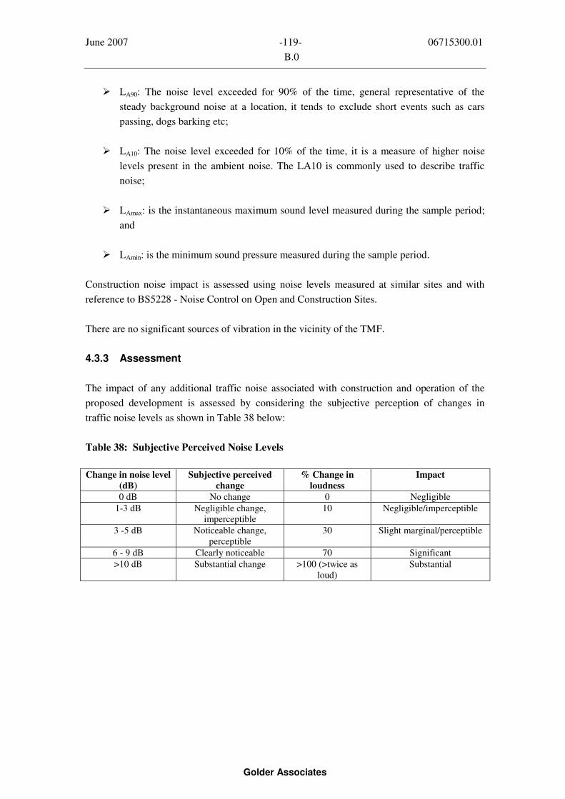
June 2007 -119- 06715300.01
B.0
Golder Associates
LA90: The noise level exceeded for 90% of the time, general representative of the
steady background noise at a location, it tends to exclude short events such as cars
passing, dogs barking etc;
LA10: The noise level exceeded for 10% of the time, it is a measure of higher noise
levels present in the ambient noise. The LA10 is commonly used to describe traffic
noise;
LAmax: is the instantaneous maximum sound level measured during the sample period;
and
LAmin: is the minimum sound pressure measured during the sample period.
Construction noise impact is assessed using noise levels measured at similar sites and with
reference to BS5228 - Noise Control on Open and Construction Sites.
There are no significant sources of vibration in the vicinity of the TMF.
4.3.3 Assessment
The impact of any additional traffic noise associated with construction and operation of the
proposed development is assessed by considering the subjective perception of changes in
traffic noise levels as shown in Table 38 below:
Table 38: Subjective Perceived Noise Levels
Change in noise level
(dB)
Subjective perceived
change
% Change in
loudness
Impact
0 dB No change 0 Negligible
1-3 dB Negligible change,
imperceptible
10 Negligible/imperceptible
3 -5 dB Noticeable change,
perceptible
30 Slight marginal/perceptible
6 - 9 dB Clearly noticeable 70 Significant
>10 dB Substantial change >100 (>twice as
loud)
Substantial
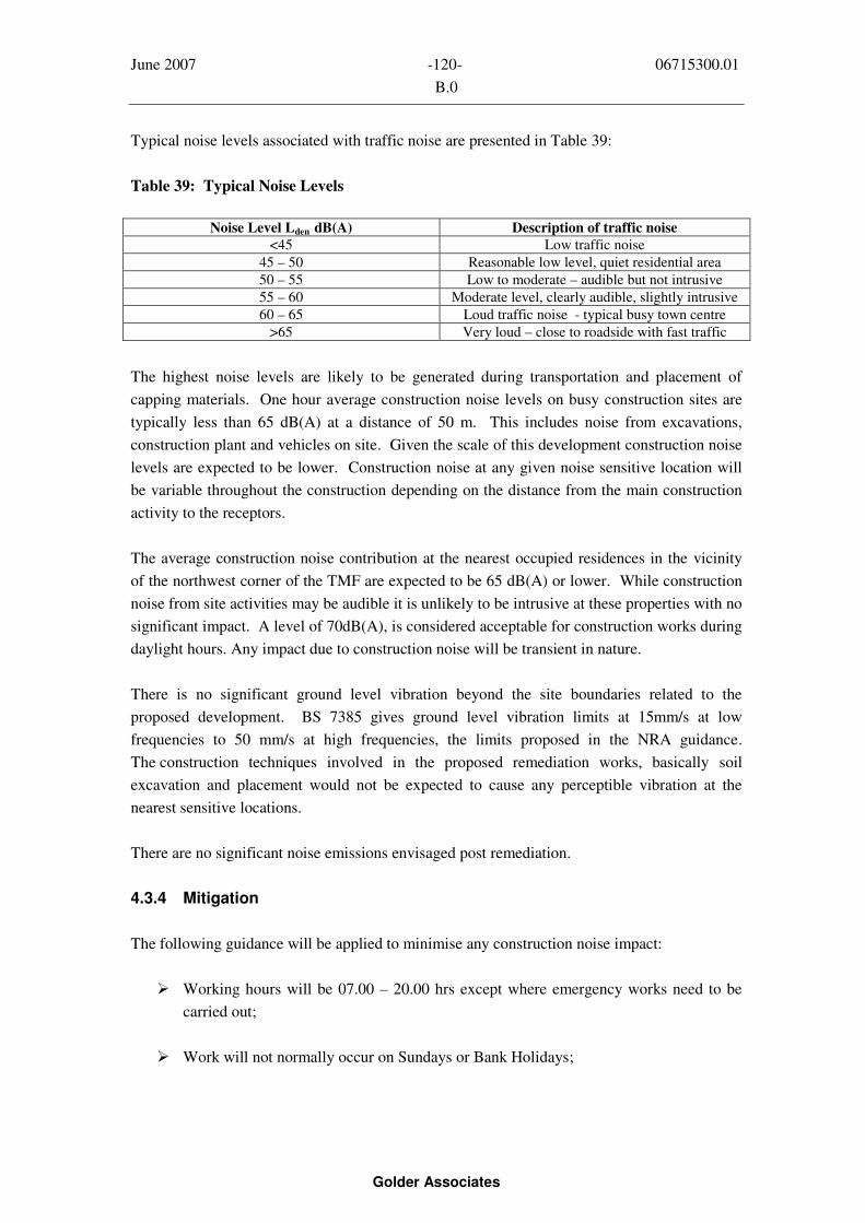
June 2007 -120- 06715300.01
B.0
Golder Associates
Typical noise levels associated with traffic noise are presented in Table 39:
Table 39: Typical Noise Levels
Noise Level Lden dB(A) Description of traffic noise
<45 Low traffic noise
45 – 50 Reasonable low level, quiet residential area
50 – 55 Low to moderate – audible but not intrusive
55 – 60 Moderate level, clearly audible, slightly intrusive
60 – 65 Loud traffic noise - typical busy town centre
>65 Very loud – close to roadside with fast traffic
The highest noise levels are likely to be generated during transportation and placement of
capping materials. One hour average construction noise levels on busy construction sites are
typically less than 65 dB(A) at a distance of 50 m. This includes noise from excavations,
construction plant and vehicles on site. Given the scale of this development construction noise
levels are expected to be lower. Construction noise at any given noise sensitive location will
be variable throughout the construction depending on the distance from the main construction
activity to the receptors.
The average construction noise contribution at the nearest occupied residences in the vicinity
of the northwest corner of the TMF are expected to be 65 dB(A) or lower. While construction
noise from site activities may be audible it is unlikely to be intrusive at these properties with no
significant impact. A level of 70dB(A), is considered acceptable for construction works during
daylight hours. Any impact due to construction noise will be transient in nature.
There is no significant ground level vibration beyond the site boundaries related to the
proposed development. BS 7385 gives ground level vibration limits at 15mm/s at low
frequencies to 50 mm/s at high frequencies, the limits proposed in the NRA guidance.
The construction techniques involved in the proposed remediation works, basically soil
excavation and placement would not be expected to cause any perceptible vibration at the
nearest sensitive locations.
There are no significant noise emissions envisaged post remediation.
4.3.4 Mitigation
The following guidance will be applied to minimise any construction noise impact:
Working hours will be 07.00 – 20.00 hrs except where emergency works need to be
carried out;
Work will not normally occur on Sundays or Bank Holidays;
June 2007 -121- 06715300.01
B.0
Golder Associates
Construction plant will be required to comply with S.I. 320 of 1998, Permissible Noise
Levels Regulations and also taking account of BS 5228 - Noise Control on
Construction and Open Sites. The contractor will select plant with low inherent
potential for noise and vibration generation. Acoustic barriers will be erected as
necessary around items such as compressors and generators and such equipment will
be sited where possible away from noise sensitive areas. Such barriers may be
proprietary types, or may consist of site materials such as earth mounds, timber or even
straw bales. Noise minimisation conditions will be included in the tender documents;
The contractor will be required to provide a site representative will be appointed for
matters relating to noise and vibration. In the event of a complaint, a site representative
will visit the complainant, discuss the problem and obtain a history and background to
it (when the noise was first heard, type of noise heard, duration and frequency of
occurrence of the noise, complainant’s belief about the source, effects of the noise on
the complainant and whether other family members hear the noise). Upon return the
information received will be reviewed and compared to noise measurements and a
response communicated to the complainant in a sensitive and respectful manner and
additional noise mitigation measures immediately employed if required;
An initial baseline survey will be carried out at two of nearest occupied residences in
advance of works commencing and monitoring for typical noise and vibration levels
during critical periods; and
All site access roads will be regularly maintained so to minimise vibration and noise
from heavy truck movements.
Such measures will adequately mitigate the impact due to construction noise at the proposed
site. There are no significant noise emissions envisaged post construction, hence no additional
mitigation measures are proposed.
4.3.5 Residual
There are no residual noise impacts envisaged post the remediation works.
4.4 Soils and Geology
4.4.1 Assessment
As indicated previously in Section 3 of this report it is proposed to place a layer of crushed
stone/rockfill and a layer of growth-medium over selected areas of the surface and dam walls
of the TMF, and to upgrade and rehabilitate the existing wetlands. These ‘capping’ materials
will be transported to the site and used directly or stored in temporary stockpiles before being
placed on the surface of the tailings.

June 2007 -122- 06715300.01
B.0
Golder Associates
On completion of the remediation works on the TMF, any areas around the perimeter of the
TMF used for the storage and handling of the growth-medium and crushed stone/rockfill will
be reinstated and seeded.
Risks posed to the natural geological environment at the site are primarily associated with
diesel and/or oil spills and leaks from both mobile and fixed plant.
4.4.2 Mitigation
The importation of crushed stone/rockfill and ‘growth-medium’ (e.g. topsoil and/or river
dredgings) are a significant impact and cannot be mitigated against as they form part of the
overall remediation and rehabilitation solution to the Gortmore site as set out in the overall
Silvermines Rehabilitation Plan as agreed between DCMNR, NTCC, interested stakeholders
and the local community.
Regarding operational activities at the Application Site, the following mitigation measures will
be employed:
1. All refuelling of mobile plant will be undertaken in temporary hardstanding areas. These
practices will have little or no effect on drift or bedrock material;
2. Mobile plant will be regularly maintained and where plant is damaged or leaking, this will
be dealt with as part of the ongoing operational management of the site; and
3. Growth-medium will be stored separately, and will be stored in prescribed thicknesses to
ensure best practicable maintenance of soil structure and fertility for use during final
restoration.
4.4.3 Residual
In the long-term, there will be no deleterious effects on the soils, overburden or bedrock caused
by the remediation and rehabilitation activities carried out on the site.
4.5 Water
4.5.1 Assessment
This section assesses any impacts of the proposed remediation solution on local surface water
and groundwater quality. In particular, it considers any likely significant effects from any
water emissions during the construction of the rehabilitation works and in the post-
rehabilitation phase.

June 2007 -123- 06715300.01
B.0
Golder Associates
The proposed works involve capping bare and poor grassland areas on the tailings surface, and
are designed to limit the long-term potential for dust generation, dispersion and deposition
from the TMF. The capped surface will be seeded with a suitable grass mixture. In addition, it
is proposed to upgrade the existing drainage and wetland treatment system around the toe of
the dam to mitigate the impact of water migrating from the surface and leaching through the
side walls and into the toe drains of the TMF.
4.5.1.1 Effects / Impacts Relating to Water Quality – General Comments
An assessment of the water quality impacts of any development is normally carried out by
calculating the contribution of water pollution from emission sources resulting with, and
without, the development. This assessment of water quality impacts is combined with
background concentrations of chemical parameters and compared with relevant water quality
criteria. Future concentrations can then be predicted with and without the proposed
development.
The background water monitoring data collected in the Gortmore area since 1999 has been
discussed in Chapter 2. The proposed works, which will involve capping the existing exposed
areas on the tailings surface and modifications to the drainage and wetlands are expected to
improve surface water quality in the vicinity of the TMF.
The proposed cap is likely to significantly improve the water quality run-off from the TMF
surface, particularly after extended dry periods where the current surface is exposed to
oxidation for a number of weeks and subsequently ‘flushed’ by heavy rainfall enabling an
oxidised layer of sediment and its associated load of mobilised heavy metals to enter the
wetlands and, ultimately the surface water system around the TMF. The proposed cap would
also reduce the impact of wind-generated erosion, (i.e. minimise dust blow from the site).
It is proposed to conduct regular water quality monitoring for 3 years post construction and to
continue to monitor for the long-term post the rehabilitation works in order to assess any
change in water quality.
4.5.1.2 Surface Water Impacts - Construction and Post Construction
The proposed capping works on the dry TMF surface are not expected to have any negative
significant impact on water quality. Improvements to the TMF surface drainage channel and
decant pond should take place during the summer months when this area is dry. If the capping
materials are stored in the vicinity of the north-west and south-east corners of the site no
significant run-off from these areas is anticipated, if mitigation measures such as silt
traps/fences, perimeter sediment/silt ditches and ponds are employed.
The existing uncontrolled discharges from the wetlands, occurring as breaches through mounds
of river-dredgings along the banks of the Kilmastulla River, will first be sealed. This will have

June 2007 -124- 06715300.01
B.0
Golder Associates
a positive impact on the river system as the water quality in these seeps is generally worse than
that entering the river at the flume discharge. Any water still passing through the old
Settlement Ponds will be diverted directly to Wetland No. 2. The drainage system through the
ponds appears to be partially blocked and the ponds themselves are saturated with
aforementioned water quality determinands, particularly manganese. Lowering the water level
in these ponds and decreasing the height of the surrounding bund walls is proposed. These
works will have a positive impact in regard to minimising the potential for seepage of water
into drains and onto adjoining lands to the north. Improvements to the TMF toe drains, as
described in Section 3, will also take place . No significant impact on water discharge quality
is expected during the completion of this work.
The proposed works will also be expected to reduce the sediment load in the adjacent rivers.
This would in turn reduce the need to dredge and dispose of contaminated sediment in the
future.
The refurbished wetland system will improve the discharge water quality into the Kilmastulla
River from the TMF site. Seepage will continue from the dam walls of the TMF but it will be
intercepted in the re-engineered toe drains, before being diverted into the refurbished wetland
system. On completion of the post-construction monitoring phase of the works any potential
impact on the receiving water can be re-assessed.
4.5.1.3 Groundwater Impacts – Construction and Post-Construction
The tailings themselves will remain saturated, with the run-off from the uppermost oxidised
layer of the tailings, either occurring as run-off through surface drains into the wetlands, or
seeps down through the tailings and dam walls into the underlying overburden and bedrock.
From recently gathered data the groundwater flow direction below the TMF is to be in a south-
westerly direction. A portion of the groundwater moving through the overburden is being
intercepted by the toe drains and wetlands along the southern and western embankments.
These toe drains also intercept pore water which is leaching through the embankment walls.
This water tends to be enriched in sulphate. In light of this, a potential pathway currently
exists for tailings pore water to migrate through the overburden and along the overburden-
bedrock interface, and subsequently through any fractures and/or fissures present in the
bedrock itself. The assessments completed to date indicate no significant groundwater impact
on any potential groundwater receptor in the Silvermines area.
The proposed remediation works are expected to have a positive impact on groundwater
quality with the improved capping drainage and wetland treatment system reducing the
uncontrolled seepages to ground and surface water.
In terms of groundwater quality post-construction, an on-going long-term monitoring
programme will be put in place to monitor the impact of leachate from the TMF on the
receiving groundwater environment (Table 40).

June 2007 -125- 06715300.01
B.0
Golder Associates
4.5.2 Mitigation
Best practicable means to minimise potential water quality impacts will be employed during
the construction phase. These measures will include:
Sealing of uncontrolled breaches to the Kilmastulla River from the wetlands, minor
improvement works to the volunteer wetlands and expanding the wetlands into the
former Settlement Ponds in the initial construction phase;
Re-engineering works to the TMF surface and toe drain structures (in select sectors) in
the initial phases of the works, to minimise the impact of uncontrolled seepage; and
Construction of silt traps and expanded wetlands to minimise any suspended solids
generated during the construction of new drains around the TMF perimeter.
In addition, on-going water quality and flow measurements of the TMF surface water and
Kilmastulla discharge will be carried out to improve on the quality of baseline data
available for future reference. Furthermore, it is recommended that ground follow-up
investigations will be carried out using 2D resistivity and possibly ground EM on
anomalies identified from the recent airborne EM survey flown over the TMF in 2006.
Depending on the findings from the ground follow-up, additional investigations on
groundwater quality may have to be initiated.
4.5.3 Residual
In the long-term, there will be no deleterious effects on the surface water or groundwater
caused by the remediation and rehabilitation activities carried out on the site.
4.6 Flora and Fauna
4.6.1 Assessment
The most valued habitats on the site from an ecological perspective are the woodland scrub and
wetland habitats. The habitats on the surface of the TMF do have some ecological value – the
‘good’ grassland is relatively diverse in species of grasses and broad-leaved herbs, and
provides a valuable wildlife habitat for mammals such as hares, grassland bird species and
invertebrate species. This grassland habitat is particularly valuable in the context of the
surrounding highly modified agricultural landscape.
The permanent Tailings Pool and wetland areas on the surface of the TMF are also
ecologically valuable as the different range of species found here enhance the biodiversity of
the site in general.
June 2007 -126- 06715300.01
B.0
Golder Associates
The woodland scrub has value for wildlife, it provides refuge and feeding sites and also
provides corridors for the movement of animals and the dispersal of plant species.
The wetland habitat is of particular ecological significance, it is not only a diverse habitat for a
range of wildlife including birds, frogs, otter, invertebrates but also functions in maintaining
the water quality of the nearby Kilmastulla River. The presence of an otter slide in one of the
Settlement Ponds shows that otter use this site.
4.6.1.1 Impacts of proposed rehabilitation works
The main impacts on habitats, flora and fauna will occur due to alteration of habitat as a result
of rehabilitation works on the surface of the TMF, and enhancement of the wetlands around the
base.
Positive impacts will occur due to the creation of a new grassland habitat. The loss of bare
mine spoil and poor grassland as a result of capping is of no ecological significance. Although
initially, as the seeded species establish, diversity of grassland herbs will be low and plants of
re-colonising bare ground may be present, it is anticipated that established grassland will be
more species rich than the existing habitats in the medium-long term.
Landscaping proposals for screening vegetation will have a positive impact on the
area – creating further habitat for flora and fauna and acting as a wildlife corridor linking
existing habitats.
While impacts will be positive in the medium-long term, some short-term negative impacts are
expected.
The loss of some wetland/marsh/wet grassland habitat which may occur due to
upgrading the wetlands is of minor negative significance as new similar wetland
habitat will replace any lost in the medium term, and mitigation measures stated below
will be followed; and
Minor negative indirect impacts may occur to areas of habitats to be retained such as to
scrub, gorse and grassland though damage from vehicles, however, these will be of a
short-term nature.
If all woodland scrub is to be retained there is no potential to impact on the habitats of birds,
bats or protected mammal species such as badgers. However, if scrub removal is necessary
mitigation measures detailed below will be followed.

June 2007 -127- 06715300.01
B.0
Golder Associates
4.6.2 Mitigation
4.6.2.1 Mitigation of potential negative impacts of rehabilitation works
Woodland scrub around the base of the TMF should be retained where possible
however, any scrub or tree removal for access should be undertaken outside of the bird
nesting period which begins on March 1st
and continues to August 31st, in order to
protect nesting birds. All birds and their nesting places are protected under the
Wildlife Act (1976) and Wildlife Amendment Act (2000);
If disturbance to the wetlands is necessary – any clearance of vegetation should be
carried out outside the bird breeding season (above) and also outside of the frog
breeding season (February to July). Frogs are also protected under the Wildlife Act;
Otter may utilise the wetland habitat and in particular the ponds. While no otter holts
were identified around the wetlands, a further survey should be conducted prior to any
proposed works on the wetlands to ensure that this protected species has not
established dwellings on-site; and
It is essential that any works carried out on the surface of the TMF or in the wetlands
does not result in an increased sediment load being released into the Kilmastulla River.
The river has stocks of salmon and trout, and lampreys breed downstream. The lower
reaches are also part of the lower river Shannon SAC.
4.6.2.2 Other recommendations
The existing wetland around the base may need to be enhanced. If necessary, it is
suggested that this is done in sections rather than the entire wetland being replaced.
This will allow existing species to rapidly colonise the new wetland areas;
New areas of wetland may need to be created. Potential locations for new wetlands
include the Settlement Ponds and the wet grassland habitat to the south of the site;
Suitable plant species for enhancing the existing wetlands or to be used in the creation
of new ones include reed (Phragmites australis), club rush (Schoenoplectus lacustris),
yellow flag (Iris pseudacorus), rushes (Juncus spp.), sedges (Carex spp.) mint (Mentha
aquatica) and bulrush (Typha latifolia); and
Planting of potential landscaping species to complement existing tree and shrub cover
around the based of the TMF (eg. rowan, alder, willow, birch and hawthorn).

June 2007 -128- 06715300.01
B.0
Golder Associates
4.6.2.3 Further work
An ecological monitoring program following re-vegetation should include the following:
The ongoing photographic record should be updated regularly for the duration of the
monitoring program;
Further monitoring of the vegetation communities on the surface, sides and around the
base of the TMF should be carried out in the 2007 field season. This survey should be
to Phase 2/NVC level (JNCC, 2006), including calculating abundance values for
quadrats/releves within each vegetation community. Based on this data, condition
assessment based on the Common Standards Monitoring Guidance for Lowland
Grassland Habitat (JNCC, 2004) could also be carried out where appropriate. Such
indicators of grassland condition will also be inputted into a multi-metric model to
determine the condition and sustainability of the newly seeded and existing grassland;
The establishment of trees on the TMF should be monitored. Gorse has expanded in
recent years, gorse expansion has also been noted on trial revegetation plots at Avoca.
It is likely that willow, alder and birch may succeed gorse to colonise the tailings.
There is an issue regarding the soil cover being potentially too thin to support trees
however, particularly if seedlings are to establish in the moss layer. Management of
establishing tree cover will be required. Trees may be susceptible to wind blow if
rooted in thin soil and/or moss, although trees may be naturally stunted due to the lack
of nutrients and thin soil cover;
Any developing bare areas should be measured. An annual walkover survey would
identify hotspots above a certain size. These would be measured to see if they are
expanding. Small-scale capping in the medium term to halt development would be
proposed if hotspots develop above a critical size;
A terrestrial invertebrate-based indicator such as the soil faunal index could be
developed to determine whether a self-sustaining vegetation community is developing;
and
A habitat enhancement programme for the Kilmastulla River at Gortmore should be
initiated in conjunction with the regional fisheries board.
4.6.3 Residual
The overall residual impact will be positive.

June 2007 -129- 06715300.01
B.0
Golder Associates
4.7 LANDSCAPE
4.7.1 Assessment
The assessment examines the extent of impacts of the proposed rehabilitation works on the
surrounding landscape and visual fields as viewed from the public domain - mainly the roads
and residences in the vicinity of the site as discussed previously.
4.7.1.1 Impacts of proposed rehabilitation works
Rehabilitation work and proposed landscaping plans will result in a significant positive impact
on the surrounding landscape and visual fields.
Planting and backfilling with soil forming materials along the TMF embankment margins
together with natural colonisation of gorse on the surface would assist in the assimilation of
this landform into the landscape in the medium to long term.
Local site visibility is limited from the sparse number of nearby residential properties
surrounding the site. Any views which do exist will again benefit from further woodland
planting around the TMF, together with plateau planting. Long distance views from the
Silvermine Mountains to the north-west will also benefit from this further site rehabilitation
and enhancement.
4.7.2 Mitigation
Extreme care should be taken during spreading operations to prevent rutting of the formation to
maintain the integrity of the crushed stone/rockfill layer. Ideally, this operation should only be
carried out when ground conditions are optimal during the summer months using low ground
pressure plant and equipment.
Livestock should be prevented from entering the site.
Further monitoring of developing and existing grassland is required. No artificial fertilization
of the ‘good grassland’ is known to have taken place in recent years and this (zero-fertilizer
input) should be continued after a ‘once-off’ spreading of fertilizer is spread on newly seeded
areas to allow for the establishment of a sustainable vegetation cover.
Tree cover should be prevented from establishing on the surface of the TMF due to the risk of
toxicity and wind-blow. Alder, willow and birch which are already growing around the base of
the TMF are likely to replace gorse, followed by ash and sycamore in the long term. The
destruction of existing grassland, woodland and wetland habitats should be minimised. These
habitats will act as seed-banks for newly establishing habitats therefore enhancing proposed
landscape planting.

June 2007 -130- 06715300.01
B.0
Golder Associates
4.7.3 Residual
The overall residual impact will be positive. Landscaping proposals are in accord with the key
landscape aims which are to be promoted in the County landscape character assessment report.
The TMF is unlikely to ever fully assimilate into the landscape, particularly when viewed from
higher ground due to its distinctive shape and height. In addition the overall visual effect of
natural grassland will not ‘match’ the neighbouring intensive agricultural land which is
typically a distinctive vivid green.
4.8 TRAFFIC
4.8.1 Assessment
Table 35 (Section 3.6) shows the estimated average daily trips (2 movements) generated by the
crushed stone/rockfill and growth-medium requirement for the full project over a 6 monthly
period.
It is proposed that two entrances to the site may be used; (i) from the north and (ii) from the
south. The use of two entrances will allow for vehicle movements to and from the site to be
scheduled and managed in a planned, and coherent way.
In the case of the Northern route the line of sight to the east and west of the Ballywilliam N7
junction is in excess of 300m. Similarly at the junction with the R499 and N7.
Traffic arriving on the northwest corner of the site will have travelled via the N7, the predicted
traffic volumes will not be significant in terms of existing traffic volumes on this main road.
The rural road will have increased traffic volumes, speed restriction will apply and haulage
scheduling will apply to minimise impact. Passing bays will be required along this route.
The Southern access to the site will have to be ‘splayed-back’ to allow for the required site
lines to be obtained.
The rural road which runs from Shallee Cross to Nenagh will have increased traffic volumes
during the course of the works. It is proposed that speed restriction and/or traffic lights be put
in place to help with traffic movements to and from the site at this entrance.
The traffic impact associated with construction workers on the site will be negligible, it is
estimated that up to approximately 20 full time persons will be employed on the site at any
time.
Once the rehabilitation work is complete, there are no significant traffic movements associated
with the on-going monitoring of the facility.
June 2007 -131- 06715300.01
B.0
Golder Associates
4.8.2 Mitigation
Mitigation measures can be realised by the following methods:
Extending the works programme for a longer period;
Extending the working day to reduce the hourly movements;
Hauling the growth-medium and crushed stone/rockfill to the site via both southern
and northern entrances, (to lessen the impact at a particular point);
Phasing the work so that the crushed stone/rockfill only is placed over a 6 month
period and the growth-medium is placed afterwards;
A construction management plan including specific routes and entrances will be
included as part of the conditions of contract for the remediation contractor and this
will be agreed with NTCC Roads Engineers in advance of haulage commencing;
Wheel wash facilities will be provided on site to ensure that construction debris will
not have an impact on the quality of roads in the surrounding area; and
Parking will be provided on site for both employees and visitors.
4.8.3 Residual
No residual impacts are envisaged as part of this Application.

June 2007 -132- 06715300.01
B.0
Golder Associates

June 2007 -133- 06715300.01
B.0
Golder Associates
5.0 ENVIRONMENTAL MONITORING
The long-term success of the proposed remediation solution at Gortmore TMF can only be
measured by a comprehensive environmental monitoring plan which will monitor performance
during the remediation works, in the immediate aftermath of remediation and on a long-term
basis. The plan will also identify requirements for any maintenance and/or repairs when
problems are encountered due to natural weathering or animal intrusion.
The monitoring plan will involve periodic monitoring for structural integrity and assurance that
the original intent of the closure is still being met. The monitoring plan post- remediation will
form part of a detailed Long-term Management Manual for the Gortmore TMF. This plan will
provide a detailed site inspection, monitoring and maintenance timetable. It will also include
procedures for maintaining/repairing the final cover, the vegetation protecting the cover
material, control of deep- rooted plants that could damage the compacted cover, maintenance
surface water drainage systems and perimeter fencing. It will also provide for response plans
that would enable remedial actions to be put into effect if unacceptable discharges or structural
problems occur.
In the event of hot-spot/vegetation die-back identified during the annual inspections in the
existing vegetated (good grass) areas, the basic remediation techniques, will be to place a
mixture of limestone dust and organic material-compost (such composts are very effective on
potentially acid generating tailings as they provide an oxygen consuming cover layer which
reduces the potential for tailings oxidation) over the affected areas and re-seed with suitable
grasses. This will prevent the growth of extensive bare areas as has currently evolved in the
bare and poor grass areas.
As regards air quality monitoring, if PM10 monitoring were to be undertaken in the Silvermines
area using standard reference techniques and equipment such as the Partisol Gravimetric
Sampler, it would be most appropriate as a permanent feature in an area of residential
population in the downwind direction i.e. for example at Silvermines Village/School.
Supporting services such as electricity and maintenance would also be available there.
The proposed monitoring programme is summarized in Table 40, while Figure 34 shows the
locations of proposed environmental monitoring points for dust, noise, and surface water. The
results of monitoring during the remediation works will be documented in a closure report.

June 2007 -134- 06715300.01
B.0
Golder Associates
Table 40: Proposed Monitoring Programme
Monitoring FrequencySample Type
(Location)
Parameter
Rehabilitation
Phase
Post
Rehabilitation
Review Comment
AirDust Deposition
(Na, N150, N300,
Sa, S150, S300,
Ea, Eb, E150,
E300, Wa, Wb,
W150, W300,
F300, F600,
Silvermines
Village, Control
Site)
Ambient Dust
Screening PM10
(Sensitive
receptors {x2})
Total Dust, Pb,
As,
PM10 (light
scattering
instantaneous
reading)
Monthly
Routinely as
required
Monthly
None
Three years
post
rehabilitation
None
Noise LAeq, LA90 ,
LA10, LAmax,
LAmin
Baseline &
during peak
activities
None None
TMF – General
Integrity
Standard
walkover
condition &
stability checks
Embankment
Settlement/
Movement
Annual safety
inspection
report
Annual
Annual
Annual
Annual
Annual
Annual
Three years
post-
rehabilitation
GroundwaterBoreholes on TMF
embankment and
at base (BH1A,
BH1E, BH1F,
BH2A, BH2C,
BH2D BH3A,
BH4A, BH4C,
BH4D, BH5A,
BH5C, BH5D,
TMF1(S)/SRK/01,
TMF1(D)/SRK/01,
TMF2(S)/SRK/01,
TMF2(D)/SRK/01
& TMF4/SRK/01
SH1/ SRK/01
Water level
pH,
Conductivity
Sulphate
Pb, Zn, As, Fe,
Hg, Mn, K, Cd,
As
Twice
annually
Annual Review
annually

June 2007 -135- 06715300.01
B.0
Golder Associates
Wetlands
Inlets and
Discharge to River
Flow, pH,
Conductivity
Sulphate,
Pb, Zn, As, Fe,
Ca, Mg, Mn, Hg
Bi-monthly Quarterly Review
annually
TMF Perimeter
Drain
Drain (min. six
No selected
locations).
Water level
pH,
Conductivity
Sulphate,
Pb, Zn, As, Fe,
Ca, Mg, Mn, Hg
Bi-monthly Quarterly Review
annually
TMF Vegetation
Recently
Vegetated areas
Good Grassland
Visual
assessment/walk
over survey of
cover condition
Plant elemental
composition
Soil nutrient
content
Plant cover
density and
diversity
Photographic
record
Quarterly Bi-annually Review
annually
Areas showing
accelerated
erosion or lack
of vegetation
would be
identified and
addressed.
If
bioaccumulation
of contaminants
is identified,
monitoring
would occur on
a more frequent
basis.
Kilmastulla River
Upstream
Downstream
Water and Stream
Sediments
pH,
Conductivity
Sulphate,
Pb, Zn, As, Fe,
Ca, Mg, Mn
Quarterly Bi-annually Three years
post
rehabilitation
Meteorological
Station
Wind
speed/direction,
Evaporation,
Precipitation,
temperature
Continuous Annual Continue for
12 months &
review
Ecology NVC Phase 2
survey (JNCC
2006)
Annual Annual Review after
3 years
TMF Tailings
Pool
pH,
Conductivity
Sulphate,
Pb, Zn, As, Fe,
Ca, Mg, Mn
Annual Annual Review after
3 years

June 2007 - 06715300.01
Golder Associates
FIGURES

June 2007 - 06715300.01
Golder Associates
APPENDICES