Embed Size (px)
Citation preview
1
Monday, February 11, 2019
Good Dirt !Trenching & Excavation Safety
Presented by Bryan Thais, INSafe Safety Consultant
Objectives
• Soil mechanics and classification
• Protective systems
• Other specific requirements of the excavation standard
1
2
2
Monday, February 11, 2019
Trenching
• New NEP October 1, 2018 - replaces 1985 program• Trenching fatalities trending upward - 120 fatalities last 5
years • 71% the last 3 years• Objective to reduce and eliminate hazards related to
trenches and excavations
• Enforcement to initiate inspections when open excavation observed – regardless of whether violation observed
• Consultation Outreach activities
Monday, February 11, 2019
Subpart P – Excavations ---(1926.650 - 652)
2017• Federal
• 1119 citations --- $5.5 million in fines• Indiana
• 46 citations --- nearly $60,000 in fines• Cave-in protection in excavations - Protective system use• Inspections by competent person• Egress from trench excavations• Protection from falling/rolling materials/equipment
3
4
3
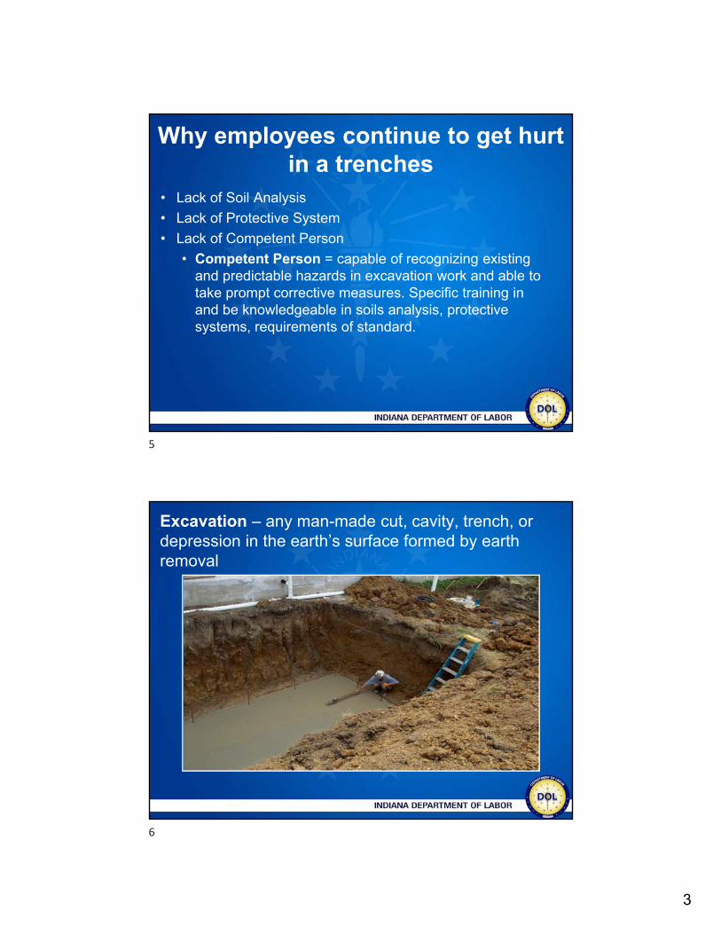
Why employees continue to get hurt in a trenches
• Lack of Soil Analysis
• Lack of Protective System
• Lack of Competent Person
• Competent Person = capable of recognizing existing and predictable hazards in excavation work and able to take prompt corrective measures. Specific training in and be knowledgeable in soils analysis, protective systems, requirements of standard.
Excavation – any man-made cut, cavity, trench, or depression in the earth’s surface formed by earth removal
5
6
4
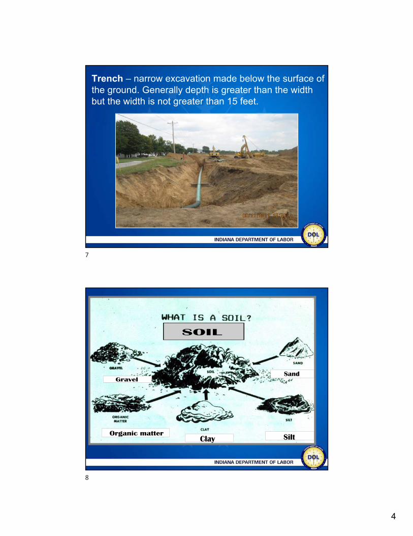
Trench – narrow excavation made below the surface of the ground. Generally depth is greater than the width but the width is not greater than 15 feet.
7
8
5
Soils and Soil Strength
• Saturation• Amount of water soil is currently holding. Complete saturation
less stable than soil that is only slightly damp. Soil with no water content is unstable
• Cohesiveness• How well the soil sticks together
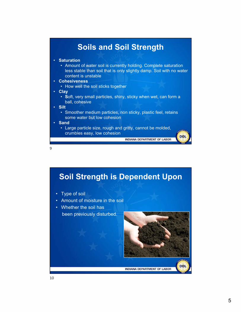
• Clay• Soft, very small particles, shiny, sticky when wet, can form a
ball, cohesive• Silt
• Smoother medium particles, non sticky, plastic feel, retains some water but low cohesion
• Sand• Large particle size, rough and gritty, cannot be molded,
crumbles easy, low cohesion
Soil Strength is Dependent Upon
• Type of soil
• Amount of moisture in the soil
• Whether the soil has
been previously disturbed.
9
10
6
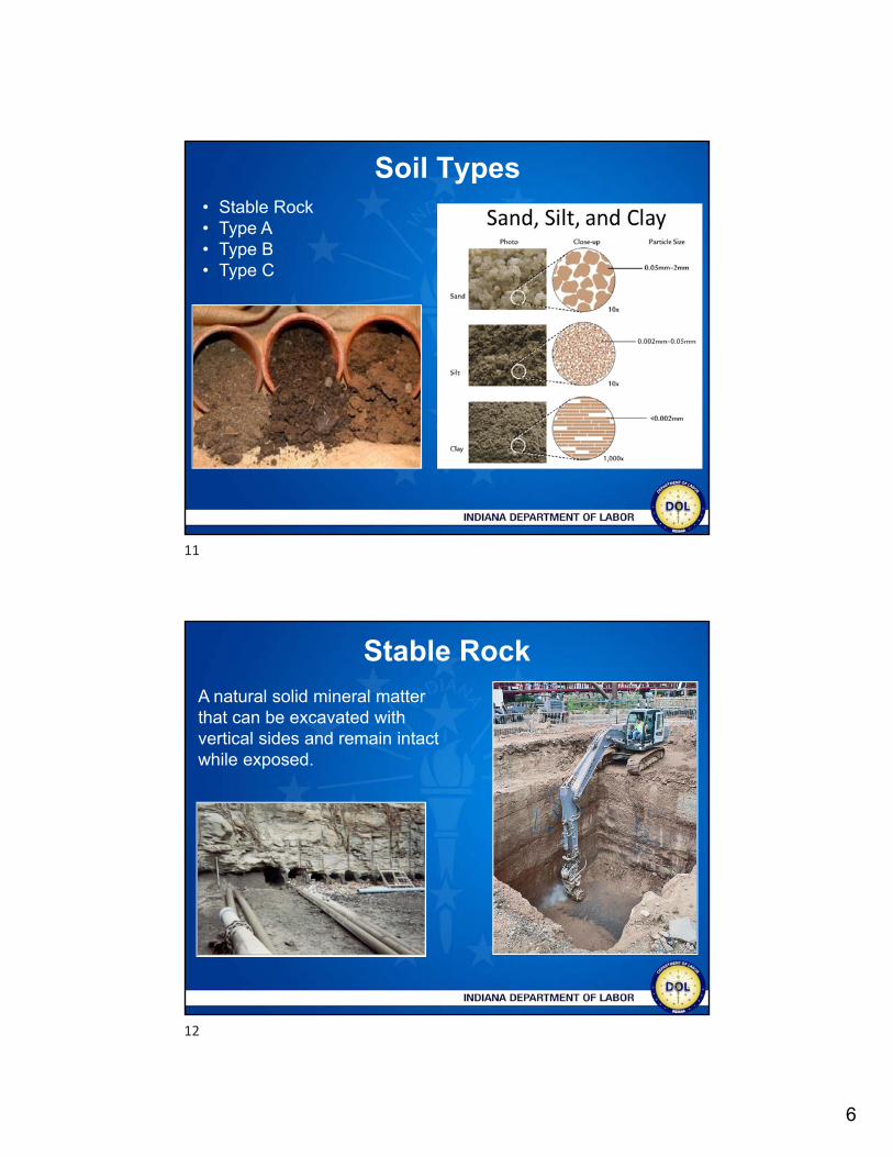
Soil Types• Stable Rock• Type A• Type B• Type C
12
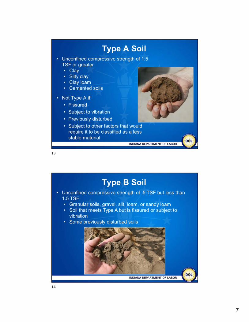
Stable Rock
A natural solid mineral matter that can be excavated with vertical sides and remain intactwhile exposed.
11
12
7
Type A Soil
• Not Type A if:
• Fissured
• Subject to vibration
• Previously disturbed
• Subject to other factors that would require it to be classified as a less stable material
• Unconfined compressive strength of 1.5 TSF or greater• Clay• Silty clay• Clay loam• Cemented soils
Type B Soil• Unconfined compressive strength of .5 TSF but less than
1.5 TSF• Granular soils, gravel, silt, loam, or sandy loam• Soil that meets Type A but is fissured or subject to
vibration• Some previously disturbed soils
13
14
8
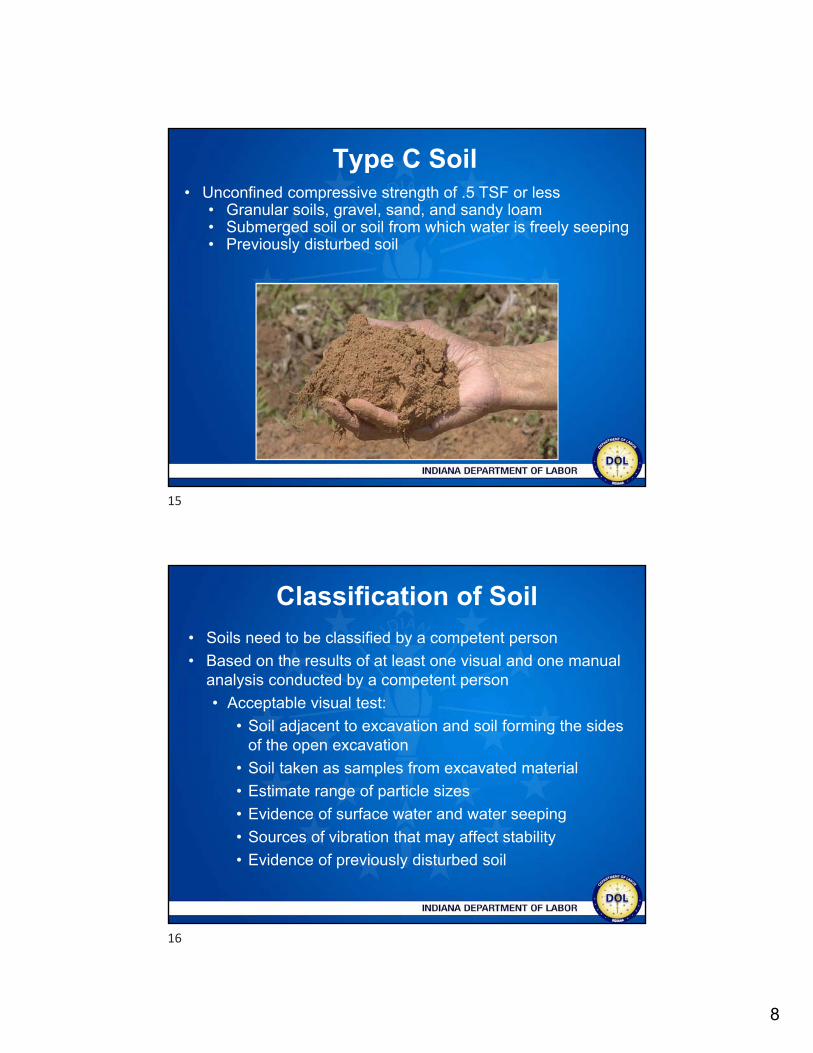
Type C Soil• Unconfined compressive strength of .5 TSF or less
• Granular soils, gravel, sand, and sandy loam• Submerged soil or soil from which water is freely seeping• Previously disturbed soil
Classification of Soil
• Soils need to be classified by a competent person
• Based on the results of at least one visual and one manual analysis conducted by a competent person
• Acceptable visual test:
• Soil adjacent to excavation and soil forming the sides of the open excavation
• Soil taken as samples from excavated material
• Estimate range of particle sizes
• Evidence of surface water and water seeping
• Sources of vibration that may affect stability
• Evidence of previously disturbed soil
15
16
9
Acceptable manual test
• Plasticity
• Ribbon and thread test
• Dry strength test
• Thumb penetration test
• Other strength test
• Pocket pentrometer
• Hand-operated shearvane
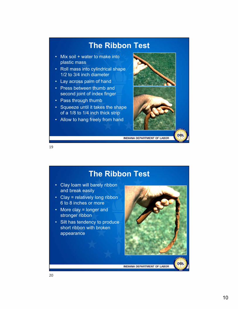
Thumb Penetration Test• Attempt to press thumb firmly into the soil in question
A. Indentation in the soil only with great difficulty
B. Thumb penetrates no further than the length of the thumb nail
C. Thumb penetrates the full length of the thumb
17
18
10
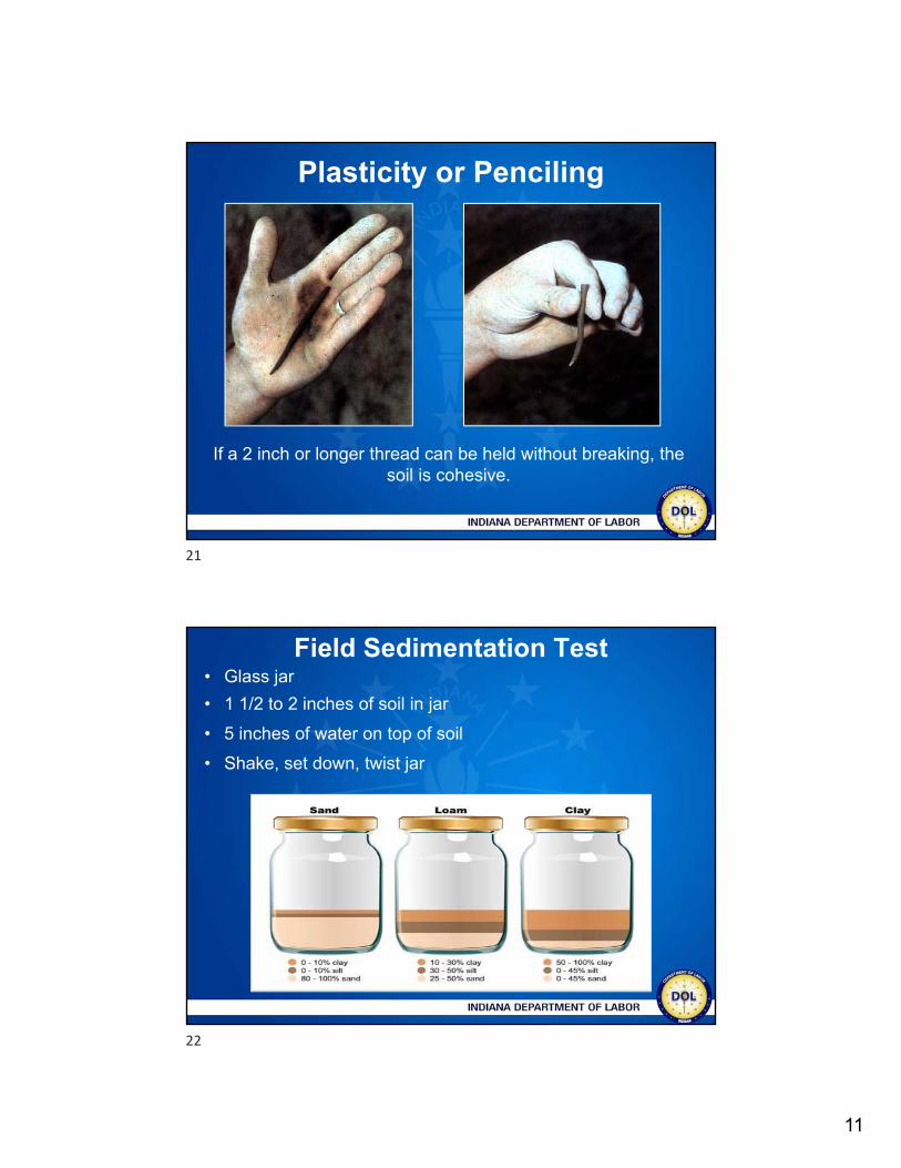
The Ribbon Test • Mix soil + water to make into
plastic mass
• Roll mass into cylindrical shape 1/2 to 3/4 inch diameter
• Lay across palm of hand
• Press between thumb and second joint of index finger
• Pass through thumb
• Squeeze until it takes the shape of a 1/8 to 1/4 inch thick strip
• Allow to hang freely from hand
The Ribbon Test • Clay loam will barely ribbon
and break easily
• Clay = relatively long ribbon 6 to 8 inches or more
• More clay = longer and stronger ribbon
• Silt has tendency to produce short ribbon with broken appearance
19
20
11
Plasticity or Penciling
If a 2 inch or longer thread can be held without breaking, the soil is cohesive.
Field Sedimentation Test • Glass jar
• 1 1/2 to 2 inches of soil in jar
• 5 inches of water on top of soil
• Shake, set down, twist jar
21
22
12
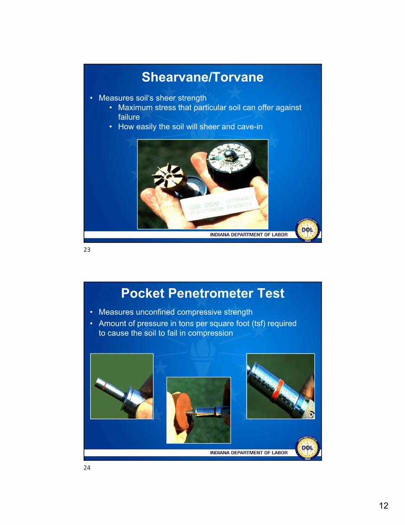
Shearvane/Torvane
• Measures soil‘s sheer strength• Maximum stress that particular soil can offer against
failure• How easily the soil will sheer and cave-in
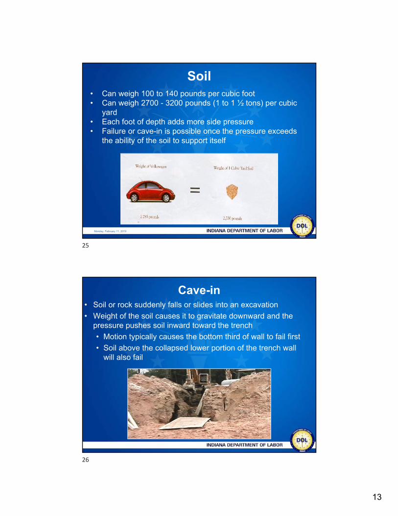
Pocket Penetrometer Test• Measures unconfined compressive strength
• Amount of pressure in tons per square foot (tsf) required to cause the soil to fail in compression
23
24
13
Monday, February 11, 2019
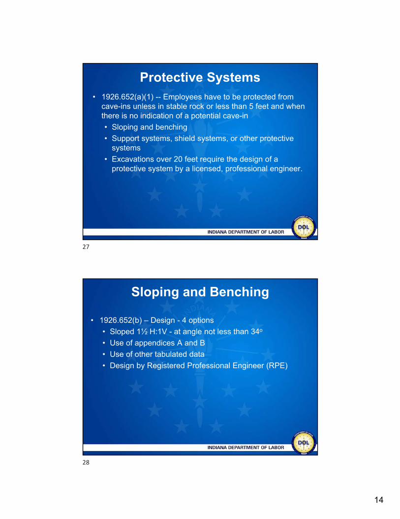
• Can weigh 100 to 140 pounds per cubic foot• Can weigh 2700 - 3200 pounds (1 to 1 ½ tons) per cubic
yard• Each foot of depth adds more side pressure• Failure or cave-in is possible once the pressure exceeds
the ability of the soil to support itself
Soil
Cave-in• Soil or rock suddenly falls or slides into an excavation
• Weight of the soil causes it to gravitate downward and the pressure pushes soil inward toward the trench
• Motion typically causes the bottom third of wall to fail first
• Soil above the collapsed lower portion of the trench wall will also fail
25
26
14
Protective Systems• 1926.652(a)(1) -- Employees have to be protected from
cave-ins unless in stable rock or less than 5 feet and when there is no indication of a potential cave-in
• Sloping and benching
• Support systems, shield systems, or other protective systems
• Excavations over 20 feet require the design of a protective system by a licensed, professional engineer.
Sloping and Benching
• 1926.652(b) – Design - 4 options
• Sloped 1½ H:1V - at angle not less than 34o
• Use of appendices A and B
• Use of other tabulated data
• Design by Registered Professional Engineer (RPE)
27
28
15
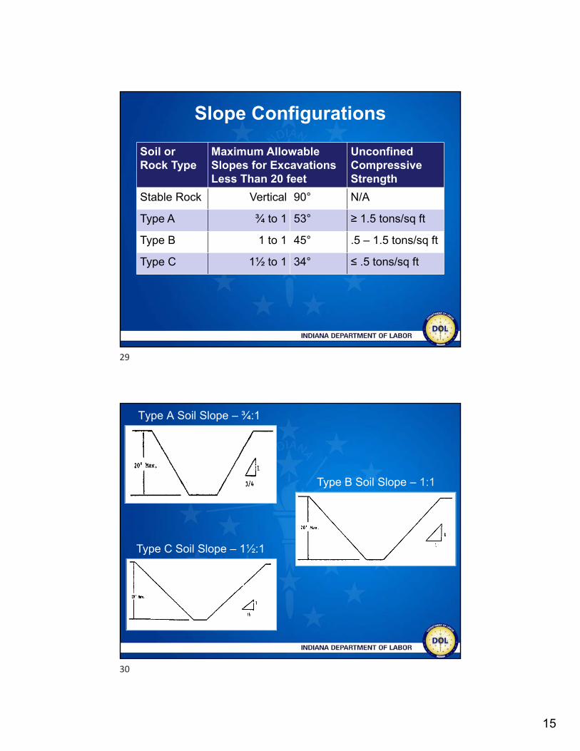
Slope Configurations
Soil or Rock Type
Maximum Allowable Slopes for Excavations Less Than 20 feet
Unconfined Compressive Strength
Stable Rock Vertical 90° N/A
Type A ¾ to 1 53° ≥ 1.5 tons/sq ft
Type B 1 to 1 45° .5 – 1.5 tons/sq ft
Type C 1½ to 1 34° ≤ .5 tons/sq ft
Type A Soil Slope – ¾:1
Type C Soil Slope – 1½:1
Type B Soil Slope – 1:1
29
30
16
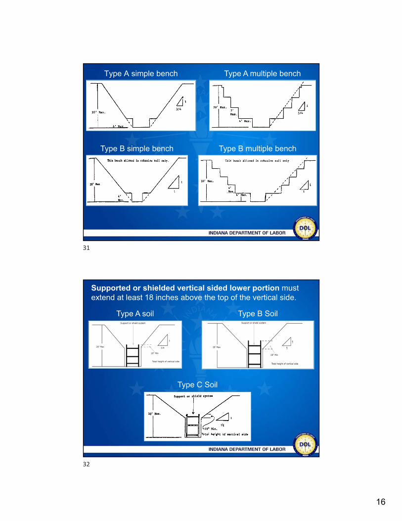
Type A simple bench
Type B simple bench
Type A multiple bench
Type B multiple bench
Supported or shielded vertical sided lower portion must extend at least 18 inches above the top of the vertical side.
Type A soil Type B Soil
Type C Soil
31
32
17
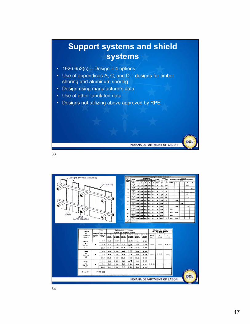
Support systems and shield systems
• 1926.652(c) -- Design = 4 options
• Use of appendices A, C, and D – designs for timber shoring and aluminum shoring
• Design using manufacturers data
• Use of other tabulated data
• Designs not utilizing above approved by RPE
33
34
18
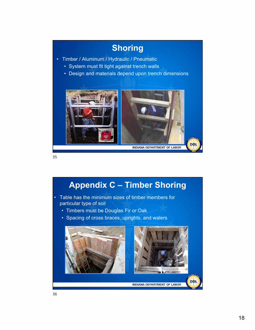
Shoring• Timber / Aluminum / Hydraulic / Pneumatic
• System must fit tight against trench walls
• Design and materials depend upon trench dimensions
Appendix C – Timber Shoring • Table has the minimum sizes of timber members for
particular type of soil
• Timbers must be Douglas Fir or Oak
• Spacing of cross braces, uprights, and walers
35
36
19
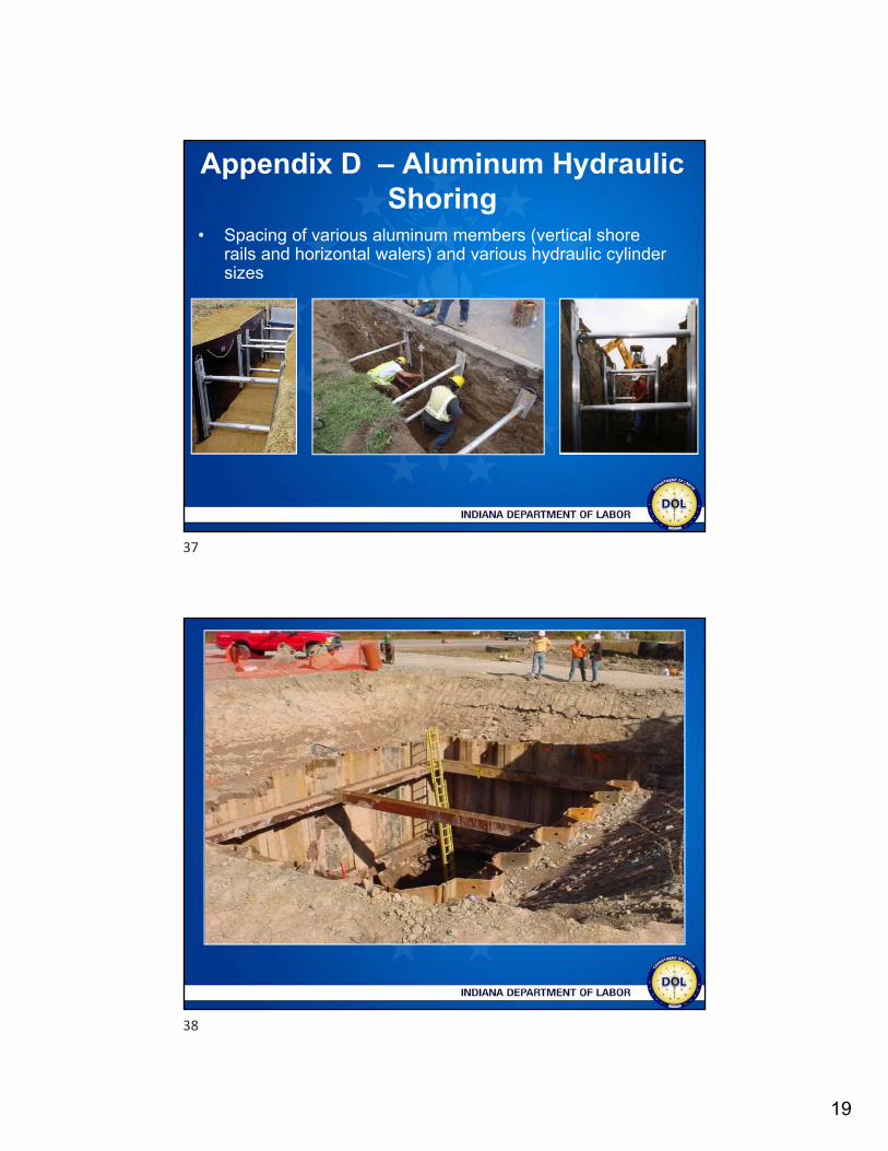
Appendix D – Aluminum Hydraulic Shoring
• Spacing of various aluminum members (vertical shore rails and horizontal walers) and various hydraulic cylinder sizes
37
38
20
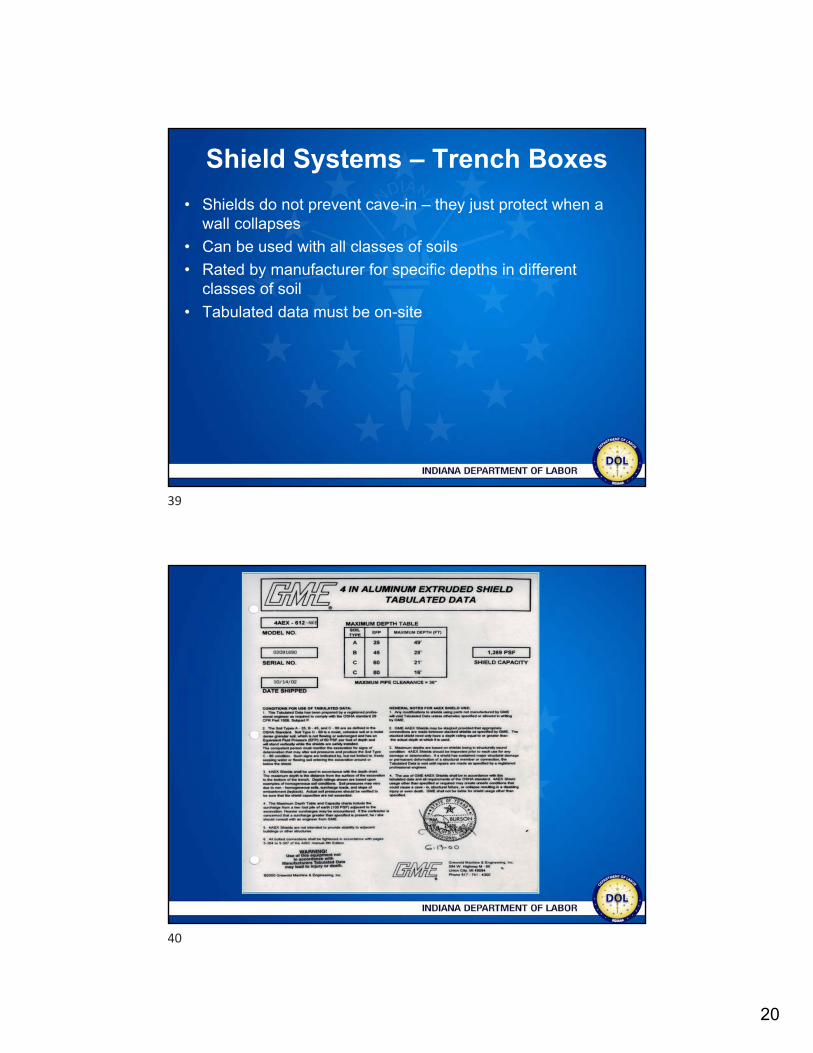
Shield Systems – Trench Boxes
• Shields do not prevent cave-in – they just protect when a wall collapses
• Can be used with all classes of soils
• Rated by manufacturer for specific depths in different classes of soil
• Tabulated data must be on-site
39
40
21
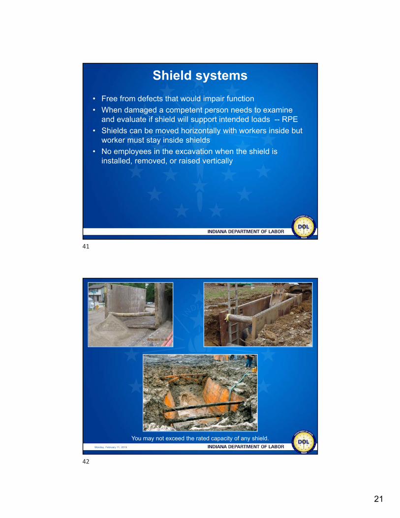
Shield systems
• Free from defects that would impair function
• When damaged a competent person needs to examine and evaluate if shield will support intended loads -- RPE
• Shields can be moved horizontally with workers inside but worker must stay inside shields
• No employees in the excavation when the shield is installed, removed, or raised vertically
Monday, February 11, 2019
You may not exceed the rated capacity of any shield.
41
42
22
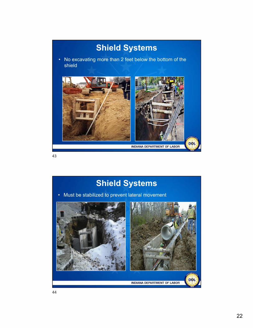
Shield Systems • No excavating more than 2 feet below the bottom of the
shield
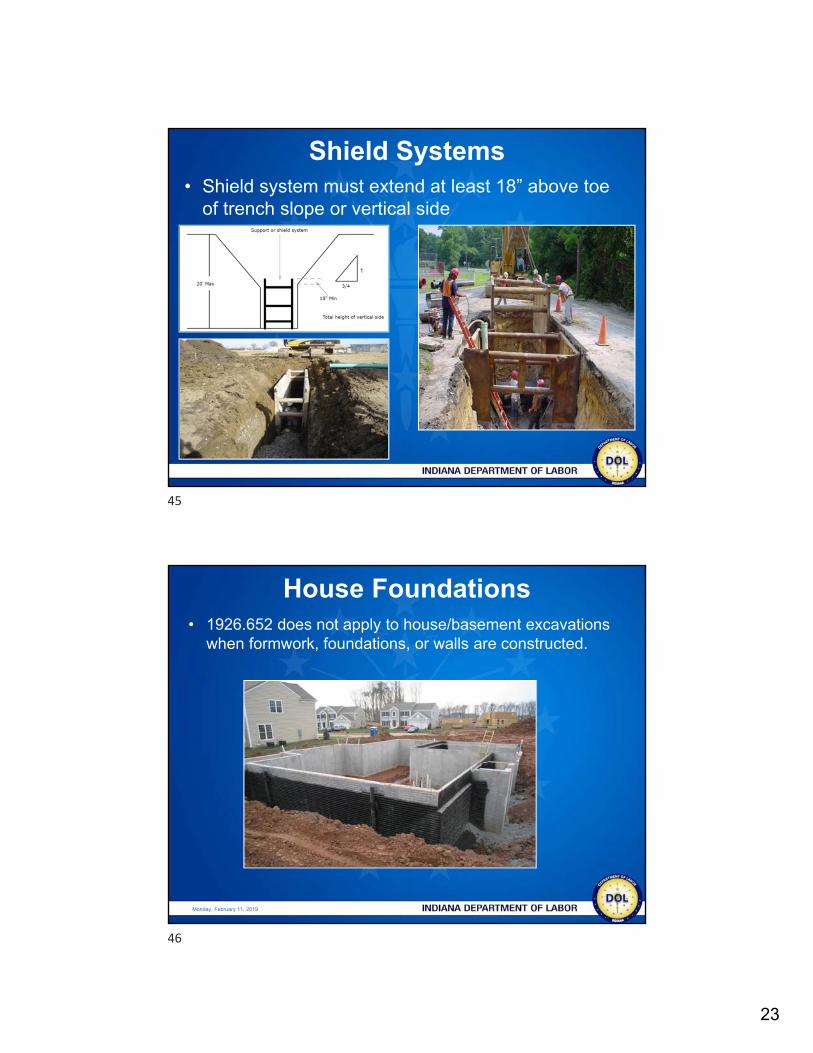
Shield Systems • Must be stabilized to prevent lateral movement
43
44
23
Shield Systems • Shield system must extend at least 18” above toe
of trench slope or vertical side
Monday, February 11, 2019
• 1926.652 does not apply to house/basement excavations when formwork, foundations, or walls are constructed.
House Foundations
45
46
24
Monday, February 11, 2019
• 1926.652 does not apply provided:• Less than seven and one-half feet in depth or is benched for at
least two (2) feet horizontally for every five (5) feet or less of vertical height
• The minimum horizontal width at the bottom of the excavation not less than two (2) feet
• No water, surface tension cracks, nor other environmental conditions present that reduce the stability of the excavation
• There is no heavy equipment operating in the vicinity that causes vibration to the excavation while employees are in the excavation
House Foundations
Monday, February 11, 2019
• 1926.652 does not apply provided:• All soil, equipment, and material surcharge loads are no closer
in distance to the top edge of the excavation than the excavation is deep
• Work crews in the excavation are the minimum number needed to perform the work
• The work is planned and carried out in a manner to minimize the time employees are in the excavation
Utility excavations (trenches) in conjunction with house foundation are not exempt
House Foundations
47
48
25
Monday, February 11, 2019
Specific Requirements
Monday, February 11, 2019
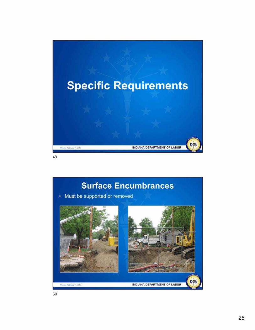
Surface Encumbrances• Must be supported or removed
49
50
26
Monday, February 11, 2019
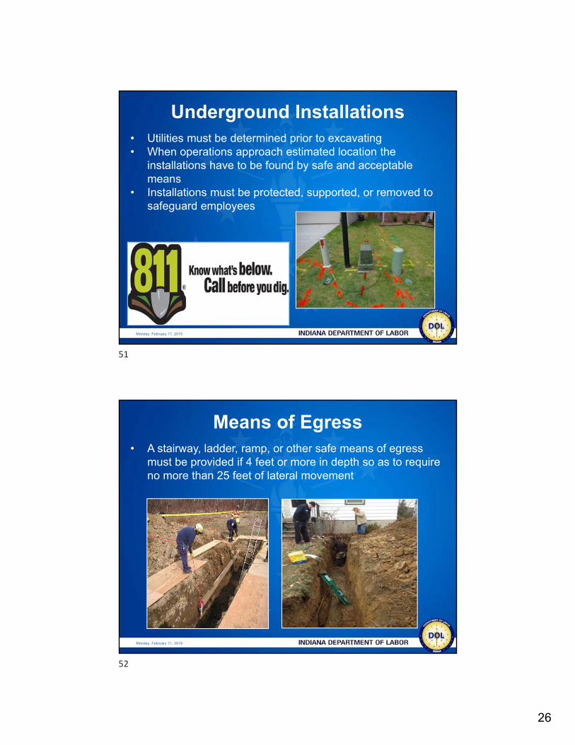
• Utilities must be determined prior to excavating• When operations approach estimated location the
installations have to be found by safe and acceptable means
• Installations must be protected, supported, or removed to safeguard employees
Underground Installations
Monday, February 11, 2019
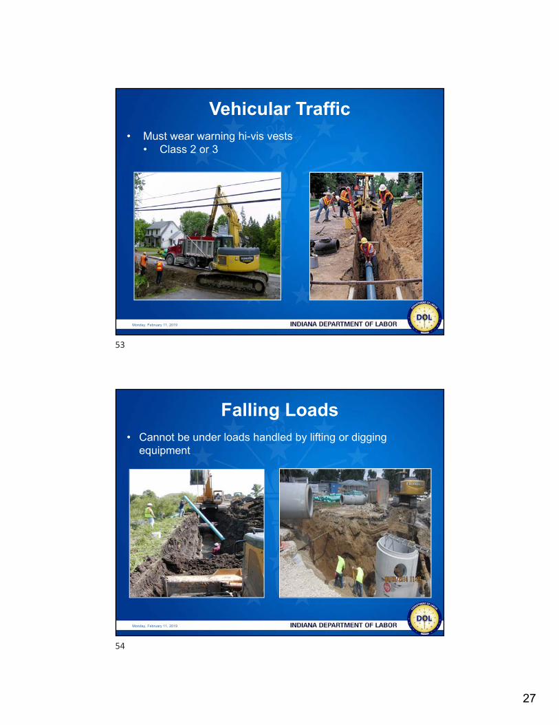
• A stairway, ladder, ramp, or other safe means of egress must be provided if 4 feet or more in depth so as to require no more than 25 feet of lateral movement
Means of Egress
51
52
27
Monday, February 11, 2019
• Must wear warning hi-vis vests • Class 2 or 3
Vehicular Traffic
Monday, February 11, 2019
• Cannot be under loads handled by lifting or digging equipment
Falling Loads
53
54
28
Monday, February 11, 2019
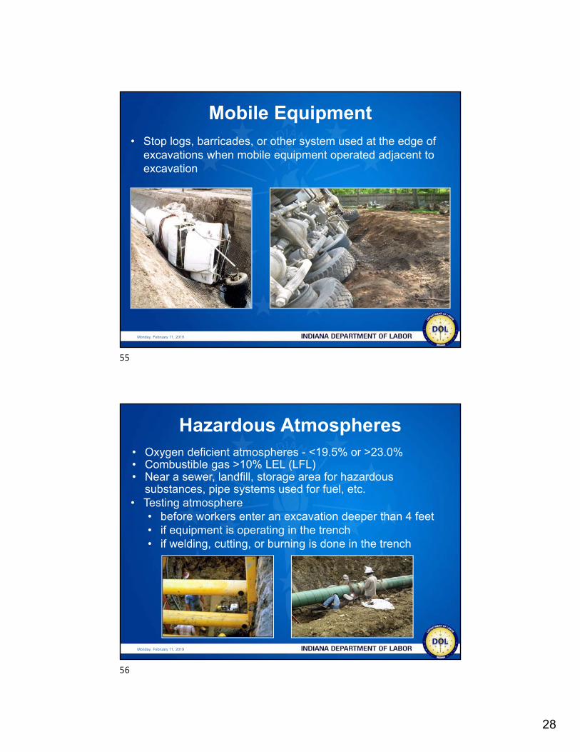
• Stop logs, barricades, or other system used at the edge of excavations when mobile equipment operated adjacent to excavation
Mobile Equipment
Monday, February 11, 2019
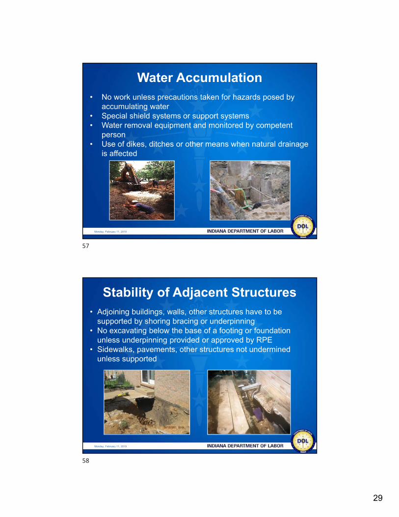
• Oxygen deficient atmospheres - <19.5% or >23.0%• Combustible gas >10% LEL (LFL)• Near a sewer, landfill, storage area for hazardous
substances, pipe systems used for fuel, etc.• Testing atmosphere
• before workers enter an excavation deeper than 4 feet• if equipment is operating in the trench• if welding, cutting, or burning is done in the trench
Hazardous Atmospheres
55
56
29
Monday, February 11, 2019
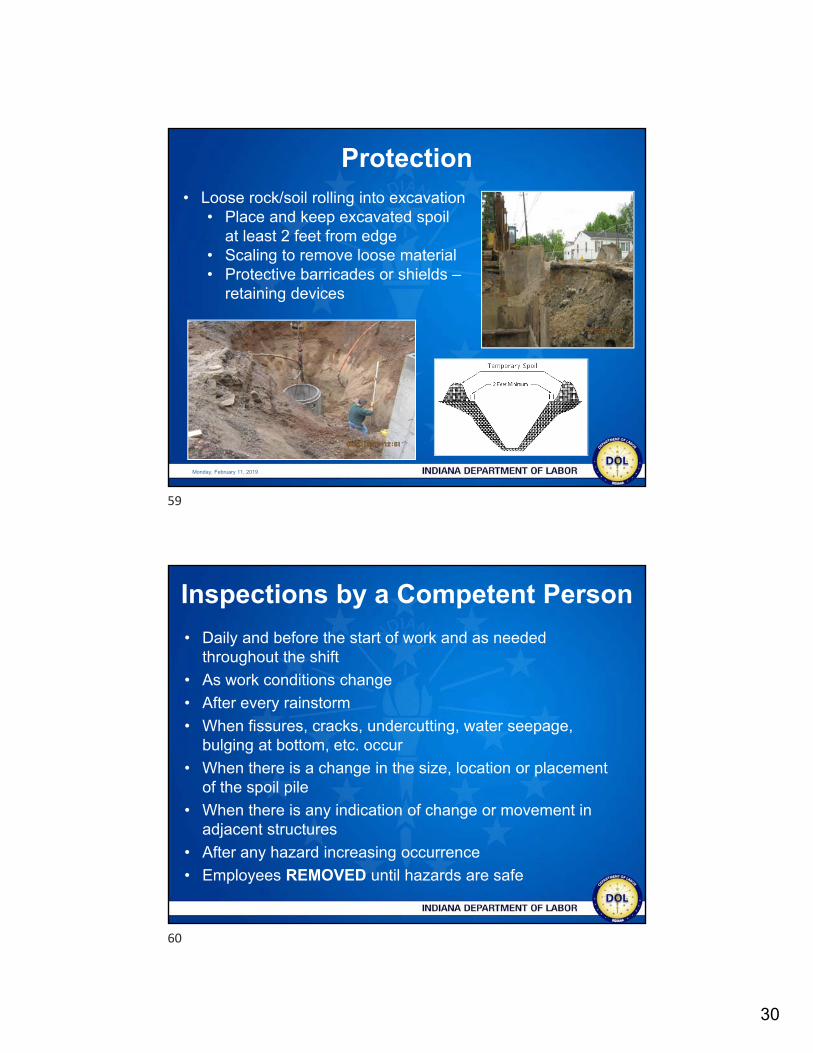
• No work unless precautions taken for hazards posed by accumulating water
• Special shield systems or support systems• Water removal equipment and monitored by competent
person• Use of dikes, ditches or other means when natural drainage
is affected
Water Accumulation
Monday, February 11, 2019
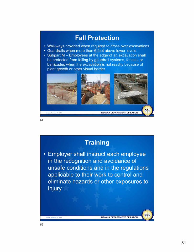
• Adjoining buildings, walls, other structures have to be supported by shoring bracing or underpinning
• No excavating below the base of a footing or foundation unless underpinning provided or approved by RPE
• Sidewalks, pavements, other structures not undermined unless supported
Stability of Adjacent Structures
57
58
30
Monday, February 11, 2019
• Loose rock/soil rolling into excavation• Place and keep excavated spoil
at least 2 feet from edge• Scaling to remove loose material• Protective barricades or shields –
retaining devices
Protection
Inspections by a Competent Person
• Daily and before the start of work and as needed throughout the shift
• As work conditions change
• After every rainstorm
• When fissures, cracks, undercutting, water seepage, bulging at bottom, etc. occur
• When there is a change in the size, location or placement of the spoil pile
• When there is any indication of change or movement in adjacent structures
• After any hazard increasing occurrence
• Employees REMOVED until hazards are safe
59
60
31
Monday, February 11, 2019
• Walkways provided when required to cross over excavations• Guardrails when more than 6 feet above lower levels.• Subpart M – Employees at the edge of an excavation shall
be protected from falling by guardrail systems, fences, or barricades when the excavation is not readily because of plant growth or other visual barrier
Fall Protection
Monday, February 11, 2019
• Employer shall instruct each employee in the recognition and avoidance of unsafe conditions and in the regulations applicable to their work to control and eliminate hazards or other exposures to injury
Training
61
62

32
Summary
• Soil mechanics and classification
• Protective systems
• Other specific requirements of the excavation standard
• Confidential* and cost-free• On-site consultation• Full or limited-scope audit• Air and noise sampling
[email protected](317) 232-2688
www.in.gov/dol/INSafeConsultation
63
64