Embed Size (px)
Citation preview

7/28/2019 Good Practice Guide Managing Installation of PV Systems
http://slidepdf.com/reader/full/good-practice-guide-managing-installation-of-pv-systems 1/28
PV LARGE-SCALE BUILDINGINTEGRATED FIELD TRIALS
GOOD PRACTICE GUIDE‘Managing Installation of PV
Systems’Contract Number: S/P2/00457
URN Number: 08/573

7/28/2019 Good Practice Guide Managing Installation of PV Systems
http://slidepdf.com/reader/full/good-practice-guide-managing-installation-of-pv-systems 2/28
DTI Good Practice Guide - Managing Installation of Large PV Systems
1
PV LARGE-SCALE BUILDING INTEGRATED FIELD TRIAL
GOOD PRACTICE GUIDE
‘Managing Installation of PV Systems’
- for building owners and developers contemplating/installing a large PV system
Contract Number: S/P2/00457
URN Number: 08/573
ContractorHalcrow Group Ltd
Subcontractors Cambridge Architectural Research Ltd
White Consulting
Prepared byEmily Rudkin
Jim Thornycroft
First Published 2008 ©Crown Copyright 2008
The work described in this report wascarried out under contract as part of the
BERR New and Renewable EnergyProgramme, which is managed by AEAEnergy & Environment. The views and judgements expressed in this report arethose of the contractor and do notnecessarily reflect those of BERR or by AEAEnergy & Environment

7/28/2019 Good Practice Guide Managing Installation of PV Systems
http://slidepdf.com/reader/full/good-practice-guide-managing-installation-of-pv-systems 3/28
DTI Good Practice Guide - Managing Installation of Large PV Systems
2
Table of Contents
1. Introduction ............................................................................................................................3 1.1 Purpose of guide ..............................................................................................................3 1.2 DTI Large Scale Building Integrated Photovoltaic (LSBIPV) Programme.......................... 3 1.3 Definition of a Larger System............................................................................................ 4 1.4 Typical Project Cycle ........................................................................................................ 4
2. Organisation...........................................................................................................................5 2.1 Who to involve in a project................................................................................................5 2.2 How many contracts / how to cover all responsibilities...................................................... 6 2.3 Tendering ......................................................................................................................... 6 2.4 Checking interface between contracts ..............................................................................6 2.5 Other interfaces ................................................................................................................7
3. Design stage .......................................................................................................................... 8 3.1 Module Choice/ Mounting Options.................................................................................... 8 3.2 Module Technology Comparison Table........................................................................... 10 3.3 Building Aesthetics ......................................................................................................... 11 3.4 Electrical Wiring/Installation............................................................................................11
3.5 Other energy efficiency measures .................................................................................. 11
4. Procurement......................................................................................................................... 12 4.1 Key Documents for PV ................................................................................................... 12 4.2 Communicating special requirements for PV to other trades........................................... 12 4.3 Checking Procurement Interfaces................................................................................... 13 4.4 Storage on site ...............................................................................................................13 4.5 Warranties...................................................................................................................... 13
5. Installation............................................................................................................................ 14 5.1 Buildability / Project timings ............................................................................................ 14 5.2 Construction sequence ................................................................................................... 14 5.3 Liaisons required (DNO, roofer, PV specialist, main contractor etc)................................ 14
6. Commissioning of system.....................................................................................................16 6.1 Interface to Electricity Network – permission to connect, metering.................................. 16 6.2 Commissioning of monitoring equipment ........................................................................ 16 6.3 Documentation and handover of PV system................................................................... 17
7. Operation & maintenance..................................................................................................... 18 7.1 System Performance / Shading ...................................................................................... 18 7.2 Auto-reclose G59/1 relays ..............................................................................................18 7.3 Identification of system failures.......................................................................................18 7.4 Training in energy efficient behaviour .............................................................................19
Appendix 1 ...............................................................................................................................20 Example table of 12 projects from the LSBIPV Programme.................................................. 20
Appendix 2 ...............................................................................................................................22 Table of Key Documents for PV............................................................................................ 22
Appendix 3 ...............................................................................................................................27 Monitoring of your PV system...............................................................................................27

7/28/2019 Good Practice Guide Managing Installation of PV Systems
http://slidepdf.com/reader/full/good-practice-guide-managing-installation-of-pv-systems 4/28
DTI Good Practice Guide - Managing Installation of Large PV Systems
3
How to set up the contracts, and questions to ask
• Posing the questions which a building owner should ask of a PV specialist, but withoutduplicating the detail of the specialist knowledge of a PV Specialist
• Focussing on the interfaces between the parties involved and the activities involvedwhich the building owner should be aware of in overseeing and setting up the project
Key Topics: •
Purpose of Guide • DTI Large Scale Building Integrated
Photovoltaic (LSBIPV) Programme
• Definition of a Larger System
• Typical Project Cycle
LSBIPV Programme Facts• Twelve large installations located
throughout the UK
• 3 ½ year programme to includeinstallation, monitoring and bestpractice recommendations
• Public buildings including schools,universities, offices, community andvisitor centres
• 640 kWp total installed capacity
• Variety of latest PV and mountingtechnologies
•
Ten new-build, two retrofit sites• Both roof and facade-mounted
installations
1. Introduction
1.1 Purpose of guide
This guide is aimed at Clients either planning or undertaking installation of Photovoltaic (PV)systems on ‘Large Scale’ buildings. These are typically owned by organisations from the publicor private sector, such as educational establishments, local government, a local community, orcommercial organisations.
It provides a step-by-step guide for people with non-specialist knowledge of PV (building ownersand developers), and is illustrated with photos and diagrams.
The structure of the document follows the ‘lifecycle’ of a project using the ‘phases’ as theheadings in the guide (e.g. design, build, commissioning, operating & maintenance).
Its main focus is to provide guidance to Clients and potential Clients on the following main
topics:
1.2 DTI Large Scale Building Integrated Photovoltaic (LSBIPV) Programme
This Guide has been based on results and findingsfrom the DTI’s Large Scale Building IntegratedPhotovoltaic (LSBIPV) programme which started in2002. In all, 12 projects were selected to be partfunded to provide detailed technical monitoring data,and also examine the ‘softer’ issues of integratingPV into the building design, organising theconstruction process, and occupier perceptions.
Further information is available in the TechnicalReports, Newsletters, and Case Studies publishedunder the programme. A brief description of the
projects can be found in Appendix 1.
LSBIPV Barnstaple Civic Centre

7/28/2019 Good Practice Guide Managing Installation of PV Systems
http://slidepdf.com/reader/full/good-practice-guide-managing-installation-of-pv-systems 5/28
DTI Good Practice Guide - Managing Installation of Large PV Systems
4
OutlineDesign
PlanningPermission
Detail Design
Building
Construction(new build)
PV Install
PV Commission
Interface PV to Electricity
Company
PV Operation
&Maintenance
PVSpecialist
1.3 Definition of a Larger System
The type of building suitable for a large scale PV system would typically have a south-facingroof or façade area sufficient to site from 200m2 to 1500m2 of PV. This would correspond to aninstalled ‘Watts Peak’ of 20 to 100kWp depending on what PV technology is used (see section 3for technical information).
Large scale PV differs from small ‘domestic’ systems in the way the projects are organised, inthat they are typically owned and operated by organisations and groups rather than individualhomeowners. This leads to different and potentially more complicated contractualarrangements as detailed in section 2.
From the technical viewpoint, there is a wider range of options for mounting the PV compared tosmall PV systems, with the buildings typically having the option to mount glass/glass see-through glazing as well as integrated and ‘semi-integrated’ systems. These are covered inmore detail in section 3. A further technical difference is the requirement for contacting theElectricity Company (Distribution Network Operator, DNO) for permission to connect in parallel
with the conventional supply which changes when above a certain installed size (see section 6).
A companion guide to this for smaller domestic systems is available from the DTI.
1.4 Typical Project Cycle
A typical project cycle for a large scale project is shown below. It shows consideration of the PVsystem right from the start of the project, right through the stages of construction andcommissioning, to operation once the building is in use.

7/28/2019 Good Practice Guide Managing Installation of PV Systems
http://slidepdf.com/reader/full/good-practice-guide-managing-installation-of-pv-systems 6/28
DTI Good Practice Guide - Managing Installation of Large PV Systems
5
‘Client’‘Client’A) ‘Client’
(Building Owner)
B) DesignConsultant/Architect
D) MainContractor forbuilding
C) PV specialist(PV Supply & DCinstallation)
E) RoofingContractor F) AC wiringcontractor
Distribution Network
Operator DNO(Connection)
Electricity Supplier(Tariffs & ROCs)
Building Control(Planningpermission)
2. Organisation
2.1 Who to involve in a project
The possible players in a construction project which includes PV are shown below. The
emphasis of the diagram will change depending on whether the building is ‘new build’, or if thePV is being added as part of an upgrade to an existing building.
In either case there are a number of options open to the Client on how to organise the projectand who to involve.
Project Organisation
Note 1 shows two options for contracting the PV Specialist – they may be sub-contracted to the Main Contractor oron a separate contract direct from the Client (see advantages/ disadvantages in text)
Note 2 shows how the PV specialist could take on the roofing and AC wiring functions as well (typically on smaller tomedium sized jobs)
(either)
(either)(or)
(or)
Key Topics:
• Who to involve in a project
• How many contracts / how to cover all responsibilities
• Tendering
• Checking interface between contracts
• Other interfaces
SeeNote 1
SeeNote 2
LSBIPV – ‘ZICER’ Building, Norwich
7/28/2019 Good Practice Guide Managing Installation of PV Systems
http://slidepdf.com/reader/full/good-practice-guide-managing-installation-of-pv-systems 7/28
DTI Good Practice Guide - Managing Installation of Large PV Systems
6
2.2 How many contracts / how to cover all responsibilities
The Client (A), typically the building owner, shown at the top of the diagram would probablyengage the services of a Design Consultant or Architect (B), especially if the project involvedother work as well as the PV system.
At this early stage, PV Specialists (C) should be asked to look at the project and suggest howtheir products could be most effectively incorporated into the building, and produce outlineestimates and technical details. Alternatively, Design Consultants who have been involved insuch schemes before, are increasingly gaining enough specialist knowledge to produce anoutline scheme and cost themselves.
To make sure the project is offered the full range of PV technology currently available as well ascompetitive prices it is recommended that several PV Specialists are contacted, as some mightrestrict themselves to particular products ranges that they are agents for.
2.3 Tendering
The main choice is then whether to let a separate contract direct with the PV Specialist, orincorporate the PV system as part of the scope of the main contractor. If there is limited otherbuilding work, the contract might be let direct from the Client to the PV Specialist. However, itwould be more normal for a larger scale project to link the work of the main contractor and thePV Specialist by writing in a ‘liaison role’ between the two. Quite often this might involve the ACwiring and roofing being physically carried out by the main contractor (or their subcontractors),but to a specification and perhaps after training (e.g. for fitting PV roof tiles) given by the PVSpecialist.
The other main option is to require that the main contractor tender for the work as part of their
contract and be fully responsible for any interfaces that there might be. This could either be bythe design consultant providing a more detailed Tender Specification for the procurement andinstallation, or more normally at the moment, by choosing a scheme from a specific PVSpecialist and then using them as a ‘Nominated Subcontractor’ for the works. Thedisadvantage to the Client of doing this might be a ‘handling charge’ from the main contractorfor taking the responsibility for this additional work in his programme.
With most projects currently being procured under the Government’s grants schemes, initialapplication for the grant is undertaken jointly between the Client and a chosen PV Specialist.However, some organisations (e.g. public bodies) will then be required to tender for the workagainst their internal procurement rules once the grant award has been authorised. If this isundertaken and the contract subsequently awarded to a second PV Specialist, occasionally, if a
significant amount of work has been undertaken at the preparation stage, the first PV Specialistmay require that this cost is refunded. It is also worth noting that the PV Specialist should be onan ‘approved’ list maintained under the scheme or by industry, to give added protection to theClient. A list of accredited solar PV installers under the grant schemes is available on theEnergy Saving Trust website www.est.org.uk.
2.4 Checking interface between contracts
Interfaces between contracts are almost as key to the success of a scheme, as having thecorrect technical design in the first place.
Whilst separating the contracts in both time and liability by completing the building first and then
installing the PV as a ‘retrofit’ would provide a solution, in practice it is normally not the mostefficient method, as potential savings both in the end-date and lack of duplicated work can bemade by a well planned integrated scheme.

7/28/2019 Good Practice Guide Managing Installation of PV Systems
http://slidepdf.com/reader/full/good-practice-guide-managing-installation-of-pv-systems 8/28
DTI Good Practice Guide - Managing Installation of Large PV Systems
7
Installing the PV as part of the fabric of the building (glass/glass façade or integrated ‘PV tiles’)is often best carried out by the ‘roofers’ with training and testing of the PV during installationcarried out by the PV Specialist. Liability for any faults in building weather-proofness wouldhave to be agreed in advance.
The responsibility for carrying out a structural assessment of the building and support structureto prove it is strong enough to carry the additional weight and wind load from the PV is also avery important interface. On a new build, the design consultant is probably best placed to havethe information to do the study for the building, with the PV Specialist providing the structuralcalculations for any framework they may install. However, information on componentmasses/sizes etc will have to be communicated between the two.
The AC wiring is also often most efficiently installed at the same time as the building’s mainelectrical wiring. Again responsibility for installing the correct cable and providing thecertification for it needs to be agreed in advance.
Where the PV is to be installed by the PV Specialist themselves, it is important to ensure that
any mounting feet/points are planned with the main roofers, so that the integrity of the roofing(and liability issues) is not compromised by adding the PV.
The final main point on interfaces is to ensure that all works are accounted for in one of thecontracts, and that there are not any unwanted surprises on reaching a late stage of theinstallation.
2.5 Other interfaces
To ensure there is no delay in waiting for permission from planning authorities, or for connectionof the system to the electricity supply, it is important for the Client to be clear what is required,and to ensure that a member of the team is responsible for each aspect.
Typically the Design Consultant would inform the Client of planning permission requirements,and seek these on their behalf. However, if the PV was in a prominent position or mountedaway from the normal building fabric, the PV Specialist would probably need to provideadditional details to support the application for planning permission.
For connection to the Distribution Network Operator’s (DNO) system, the PV Specialist wouldusually make the Client aware of requirements. However the final Agreements are usuallysigned between the Client and the DNO.
Tariffs, ROCs (Renewable Obligation Certificates), and installation of an ‘export meter’ areagain commercial arrangements between the Client and an Electricity Supplier. Although the
PV Specialist can usually provide links to further information, it is usually the Client whoprogresses this, as similar to Supply contracts it is usual for these to be changed over thelifetime of the system.
DC Wiring of PV modules Inverter with DC switch AC wiring at distribution board
7/28/2019 Good Practice Guide Managing Installation of PV Systems
http://slidepdf.com/reader/full/good-practice-guide-managing-installation-of-pv-systems 9/28
DTI Good Practice Guide - Managing Installation of Large PV Systems
8
3. Design stage
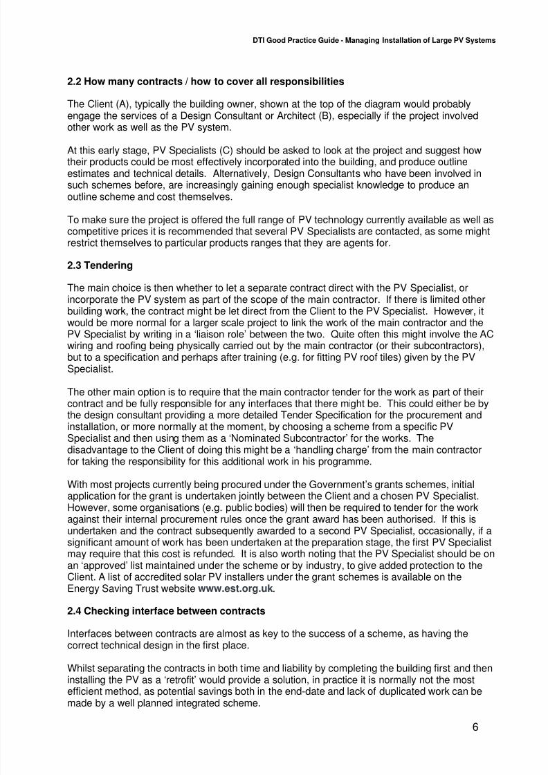
3.1 Module Choice/ Mounting Options
Below are examples of the main module technology choices illustrated from the 12 LSBIPV
projects.
Very relevant to the building designer is how the PV is fitted to, or now more normally integratedinto, the fabric of the building. Examples are given below from the LSBIPV Programme.
Three mounting types/ integration methods not represented in the field trial are a ‘console’usually mounted on a flat roof secured by its own self weight, ‘semi-integrated’ where modulesare fitted into a glazing frame which forms part of the weather seal of the roof, and ‘tile’ systemswhich are very similar to the slate systems.
Example photos of modules/ mounting arrangements used
Different Types of PV Mounting Options – frames/integrated
Module Choice
(examples from LSBIPV Projects)
Flexible roofing
e.g.Unisolar SHR17
(West Oxfordshire DistrictCouncil offices - WODC)
Integrated Glass/Glass- roof/ façade/ atrium
e.g.SolarNova glass/glasslaminates
(WODC, ZICER Centre,Insolvency Service,
BELB primary school)
Key Topics:
• Module Choice / Mounting Options
• Module Technology Comparison Table
• Building Aesthetics • Electrical Wiring/Installation
• Other energy efficiency measures
LSBIPV – OpTIC Centre, Wales

7/28/2019 Good Practice Guide Managing Installation of PV Systems
http://slidepdf.com/reader/full/good-practice-guide-managing-installation-of-pv-systems 10/28
DTI Good Practice Guide - Managing Installation of Large PV Systems
9
Slate
e.g.Atlantis Sunslates (ColumbaCentre)
Bolt on - Crystalline (over roof)
e.g.
• BP585 (Cotswold Water Park)• BP2150F (Gaia Energy Centre)
• BP5170 (St Mary’s Church)
• Photowatt PW1650 (Universityof Gloucestershire)
• BP5170 (Barnstaple CivicCentre)
Bolt on -Thin Film
e.g.• Kaneka LS202 (Birmingham
High Performance Centre)• Shell ST36 Copper-Indium-
Diselenide (OpTIC Centre)
Tile(Not used on LFT)
Similar to ‘slate’ but often in widerstrips.
Semi-integrated(Not used on LFT)
Standard modules but put into
roof so that they provide part ofthe roof weatherproof skin.
Console(Not used on LFT)
Free-standing, weighted byballast
7/28/2019 Good Practice Guide Managing Installation of PV Systems
http://slidepdf.com/reader/full/good-practice-guide-managing-installation-of-pv-systems 11/28
DTI Good Practice Guide - Managing Installation of Large PV Systems
10
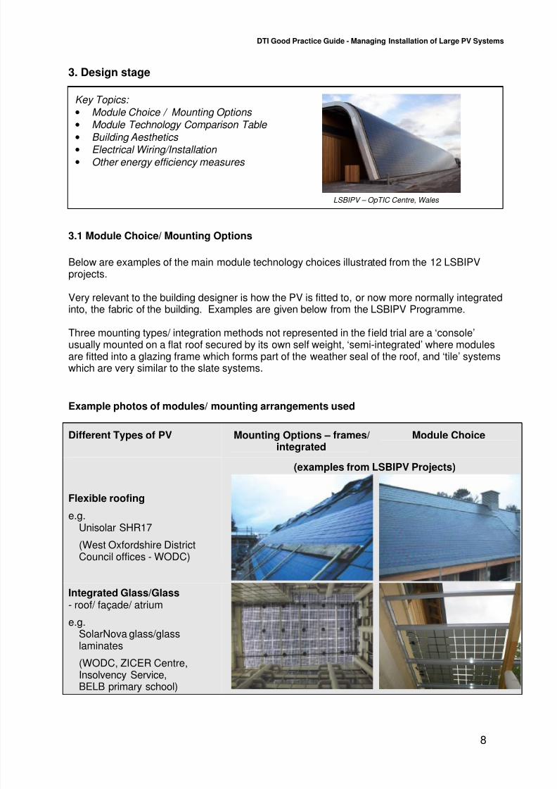
3.2 Module Technology Comparison Table
There are two main types of PV cells which are used to make up the ‘active area’ of PV
modules/ products. The more traditional choice has been crystalline PV either polycrystalline ormonocrystalline, in which the modules are made up of individual cells wired together. The otheroption is ‘thin film’ where an amorphous coating is laid down as a ‘continuous’ process.
Typically thin film gives a more uniform black appearance, but requires a greater area togenerate the same amount of electricity, as shown in the table below. Also becoming morecommon now is a ‘hybrid’ technology which uses a combination of both to produce the highestefficiency. Figures (indicative only) are quoted ‘per unit area’ (m2), which is the most commonmeasure used in the building industry.
‘Hybrid(see note) Monocrystalline Polycrystalline ‘Thin Film’
Efficiency
(at STC, seenote)
Excellent(17-19%),Excellent in overcast
Very Good(14-16%),Good in overcast
Very Good(11-13%),Good in overcast
Good(7-8%),Excellent in overcast
Area requiredper ‘kWp’
(m2 /kWp)
(see note)
6.5m2
modules 7m2
Modules10m
2slates
8-30m2
glass/glass(depending on cellspacing)
8m2
Modules10m
2Tiles
10-30m2
glass/glass(depending on cellspacing)
16m2
Modules23m
2Flexible
roofing25m
2glass/glass
Annualelectricity‘Units’ per area
(kWh/yr/m2)
(see note)
125-135 per m2
105-110 per m2
90-95 per m2
55-60 per m2
Annual CO2
savings perarea
(kg/m2)
55-60 per m2
45 per m2
40 per m2
25 per m2
Notes: STC (Standard Test Conditions): 25oC, light intensity 1000W/m
2, air mass 1.5
kWp = kW generated at STCAnnual electricity units per area are based on South facing, at 30
otilt
‘Hybrid’ is a combination of both crystalline & thin film technologies
Note: Figures are indicative only – check manufacturer’s data for specific products

7/28/2019 Good Practice Guide Managing Installation of PV Systems
http://slidepdf.com/reader/full/good-practice-guide-managing-installation-of-pv-systems 12/28
DTI Good Practice Guide - Managing Installation of Large PV Systems
11
3.3 Building Aesthetics
The type of module chosen and its mounting system will have a considerable effect on theaesthetics of the building. In well chosen combinations which compliment the style andmaterials of the building the aesthetics are often enhanced, as well as giving the building a high
tech and environmental image.
Appendix 1 shows photographs of the results achieved on the buildings within the LBIPVProgramme, using a range of products available at the time of building.
3.4 Electrical Wiring/Installation
Electrical installation is covered in some detail in the PV Installation Guide presented in Section4 of this guide.
Important points for Clients to be aware of are that the installation on the module side of the
inverters is ‘DC’ which is not always commonly used by electricians in their normal work. Inaddition, because of special ‘current limiting’ properties of PV cells, these circuits cannot beprotected against faults by normal fuses in the same way that standard power circuits are, andso again special measures are taken as described in the Guide and advised by the PVspecialist.
The ‘inverter’ provides an interface to the normal electricity supply in the building, with theoutput being ‘AC’ allowing the system to operate in parallel with the other generators and loadson the system. Part of the requirements for connection in parallel is a protection relay (‘G59/1’for bigger systems) or inverters which incorporate a similar function (‘G83/1 tested’) for smallersystems. At the present time there are about half a dozen manufacturers with products ‘typetested’ to the G83/1 requirements.
The AC wiring is essentially the same as used for other building systems and if feasible shouldbe installed by the contractor during the other work on the building.
3.5 Other energy efficiency measures
PV is only one of a number of measures that can be designed into a building to reduce itsenergy use and CO2 emissions.
PV should be complemented with other energy efficiency measures such as insulation toreduce heat loss from the building envelope, energy efficient technology, and perhaps other
renewable energy technologies. Passive solar design can also significantly reduce the energydemands of a building. New larger scale buildings are likely to be designed to the BREEAMratings on energy efficiency, which usually exceed Building Regulation requirements.
7/28/2019 Good Practice Guide Managing Installation of PV Systems
http://slidepdf.com/reader/full/good-practice-guide-managing-installation-of-pv-systems 13/28
DTI Good Practice Guide - Managing Installation of Large PV Systems
12
Key Topics:
•
Key documents for PV • Communicating special requirements for PV to other trades
• Checking Procurement Interfaces
• Storage on site
• Warranties
4. Procurement
4.1 Key Documents for PV
Key documents to be aware of are shown in the table in Appendix 2. It would be useful for the
Client to be aware of the existence of the documents and to check that the system is beingdesigned and installed using their guidance and requirements, but it would not be necessary toread them in depth:
4.2 Communicating special requirements for PV to other trades
The documents in Appendix 2 can be used to specify the particular requirements to other
trades.
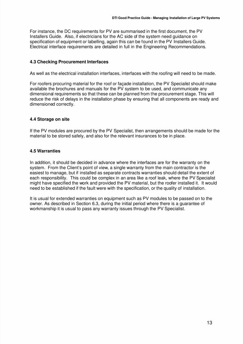
The ‘Photovoltaics in Buildings - Guide to theinstallation of PV systems, 2nd edition’ is the main‘best practice guide for PV, with references tomany of the documents in the Appendix
‘Engineering Recommendation G59/1’is the Electricity Industry Recommendation forconnection of large generators.
LSBIPV – Columba Centre, Islay
7/28/2019 Good Practice Guide Managing Installation of PV Systems
http://slidepdf.com/reader/full/good-practice-guide-managing-installation-of-pv-systems 14/28
DTI Good Practice Guide - Managing Installation of Large PV Systems
13
For instance, the DC requirements for PV are summarised in the first document, the PVInstallers Guide. Also, if electricians for the AC side of the system need guidance onspecification of equipment or labelling, again this can be found in the PV Installers Guide.Electrical interface requirements are detailed in full in the Engineering Recommendations.
4.3 Checking Procurement Interfaces
As well as the electrical installation interfaces, interfaces with the roofing will need to be made.
For roofers procuring material for the roof or façade installation, the PV Specialist should makeavailable the brochures and manuals for the PV system to be used, and communicate anydimensional requirements so that these can be planned from the procurement stage. This willreduce the risk of delays in the installation phase by ensuring that all components are ready anddimensioned correctly.
4.4 Storage on site
If the PV modules are procured by the PV Specialist, then arrangements should be made for thematerial to be stored safely, and also for the relevant insurances to be in place.
4.5 Warranties
In addition, it should be decided in advance where the interfaces are for the warranty on thesystem. From the Client’s point of view, a single warranty from the main contractor is theeasiest to manage, but if installed as separate contracts warranties should detail the extent ofeach responsibility. This could be complex in an area like a roof leak, where the PV Specialistmight have specified the work and provided the PV material, but the roofer installed it. It wouldneed to be established if the fault were with the specification, or the quality of installation.
It is usual for extended warranties on equipment such as PV modules to be passed on to theowner. As described in Section 6.3, during the initial period where there is a guarantee ofworkmanship it is usual to pass any warranty issues through the PV Specialist.

7/28/2019 Good Practice Guide Managing Installation of PV Systems
http://slidepdf.com/reader/full/good-practice-guide-managing-installation-of-pv-systems 15/28
DTI Good Practice Guide - Managing Installation of Large PV Systems
14
5. Installation
5.1 Buildability / Project timings
The construction sequence is particularly important in meeting overall timetables, and inreducing project costs by avoiding duplicated or repeated work.
An example would be fitting of mounting feet/points during the roof construction, so that theweather seal and the associated warranties were not affected by the PV fitted later in thesequence.
5.2 Construction sequence
In some projects it has been noted that where the PV Specialist was not involved early in the
construction with the roofing / mounting of the PV, complications have arisen which took extraexpense and delay compared with if the work had been planned from the outset (see section2.4).
The same can also be true of the electrical installation where inverters and AC wiring have beenundertaken by the building AC contractor later in the build programme when the PV Specialist isno longer on site. Locations of equipment and specifications of components have beenchanged without the PV Specialists knowledge, and on commissioning either has to be returnedto specification or a non-optimal solution accepted.
5.3 Liaisons required (DNO, roofer, PV specialist, main contractor etc)
These have been covered in the earlier section on project organisation, but it should bereiterated here that all parties should be in contact throughout the programme. The client canhelp to facilitate this, although much should be laid down in the original organisational structurefor the project.
The main points are:• Continued liaison is essential between trades/contractors once on site• Clarification of responsibility is required between the PV contractor and other contractors
(i.e. roofing and electrical contractors)
The following table illustrates the possible interfaces on a project in more detail, and hence thecommunication channels required. Whilst many other combinations of interfaces are possible,the ones shown in the table are most suited to the industry at present:
Key Topics:
• Buildability / Project timings
• Construction sequence • Liaisons required (DNO, roofer, PV specialist,
main contractor)o Continued liaison between
trades/contractors once on site o Clarification of responsibility between
contractors
LSBIPV OpTIC Centre, Wales

7/28/2019 Good Practice Guide Managing Installation of PV Systems
http://slidepdf.com/reader/full/good-practice-guide-managing-installation-of-pv-systems 16/28
DTI Good Practice Guide - Managing Installation of Large PV Systems
15
PV supply DC wiring Roofinstallation
AC wiring PV SystemCommission-ing
Notes
Option 1 PV Specialist PV Specialist Roofcontractor
withsupervisionby PVSpecialist
Electricalcontractor
withsupervision byPV Specialist
PV Specialist Most usual option
Option 2 PV Specialist PV Specialist Roofcontractorwithsupervisionby PVSpecialist
PV Specialist(or theirsubcontractor)
PV Specialist Variation if no AC wiringbeing done on site (e.g.retrofit)
Option 3 PV Specialist PV Specialist PV Specialist PV Specialist(or their
subcontractor)
PV Specialist Not a usual optionunless installing a
framed retrofit system
Option 4 PV Specialist Electricalcontractorwithsupervisionby PVSpecialist
Roofcontractor
Electricalcontractor
Not usual, but roofercould do DC ‘plug &skts’ on roof, with PVSpecialist testing as itgoes in
7/28/2019 Good Practice Guide Managing Installation of PV Systems
http://slidepdf.com/reader/full/good-practice-guide-managing-installation-of-pv-systems 17/28
DTI Good Practice Guide - Managing Installation of Large PV Systems
16
Key Topics:
•
Interface to Electricity Network – permission to connect, metering • Commissioning of monitoring equipment
• Documentation and handover of PV system
6. Commissioning of system
6.1 Interface to Electricity Network – permission to connect, metering
After the DC side of the system has been commissioned (see PV Installers Guide), the
Distribution Network Operator (DNO) may wish to witness the final commissioning of theprotection relay, and connection of the system in parallel with the normal electricity supply to thebuilding. This will be after the correct procedure of notification outlined in section 1 (see PVInstallers Guide).
As also noted there might be the need to sign a ‘Parallel Connection Agreement’ with the DNOto agree the technical basis for connecting to the electricity grid.
Metering provided with the PV system is normally limited to fitting of a meter after the invertersbut before any building loads are taken from the supply. This will record the full kWh (‘units’ ofelectricity) generated by the renewable generator, and if the correct type of meter andregistered for collection of ‘ROCs’ could be eligible for Renewable Obligation Certificates toreceive additional payments for producing renewable electricity. Although the meter might beinstalled by the PV Specialist, the commercial arrangements would need to be made by or onbehalf of the Client.
The same applies for receiving payments for exported units of electricity where the Client wouldneed to negotiate with their Electricity Supplier (or an alternative supplier) for a suitablecommercial deal for the sale of surplus electricity. The PV Specialist could advise on the likelysize of export based on usage figures for the building supplied for the Client.
6.2 Commissioning of monitoring equipment
Most PV inverters have a display on each unit or a data port for connecting to a laptop orpermanent computer monitoring system. These are used during commissioning and also tomonitor the long term performance of the system if the computer data-logging system isinstalled. It is also usual in large buildings visited by a significant number of people to include awall display to give a real time digital readout of typically:• Instantaneous generation of kW from the system
• Cumulative generation of kWh since commissioning and/or daily generation in kWh• Amount of CO2 saved by being a ‘green’ electricity source
More sophisticated systems can be installed to enable a more detailed analysis (see Appendix3).
LSBIPV – BELB Primary School, Belfast
7/28/2019 Good Practice Guide Managing Installation of PV Systems
http://slidepdf.com/reader/full/good-practice-guide-managing-installation-of-pv-systems 18/28
DTI Good Practice Guide - Managing Installation of Large PV Systems
17
6.3 Documentation and handover of PV system
When the work has been completed, the system should be fully checked and tested. Any testresults will be recorded on a commissioning record (see PV Installers Guide), and this will besigned by an authorised signatory to confirm the work is satisfactory.
When the work has been completed, the Client should be given a copy of this commissioningrecord together with relevant conformity certificates and guarantees. The Specialist will alsogive the Client full operating and maintenance instructions, along with a full description of thesystem. All the documents provided should be written in plain English.
Handover documentation should also be accompanied by a Warranty for the system includingequipment (usually comprising manufacturers warranties), and workmanship. It would be usualfor the PV system to be warranted for a certain period through the one point of contact with thePV Specialist, so that any diagnostics and remedial work would be carried out by the Specialistas part of that Warranty.
Although there is no agreed standard method of specifying it yet, it is recommended that theClient request some form of guarantee of performance from the Specialist. This is to ensure aguaranteed minimum output from their PV system (normally over a year). Most warranties onlycover for failures of components in the PV system. However in the LSBIPV programme, therehave been instances where parts of the Client’s system have underperformed without failureand this has not been covered under the Warranty.
It is also recommended that the Client inform their insurance company that PV is mounted onthe building, and check whether there are any additional requirements from their insurer.

7/28/2019 Good Practice Guide Managing Installation of PV Systems
http://slidepdf.com/reader/full/good-practice-guide-managing-installation-of-pv-systems 19/28
DTI Good Practice Guide - Managing Installation of Large PV Systems
18
Key Topics:
• System Performance / Shading
• Auto-reclose G59/1 relays • Identification of system failures • Training in energy efficient behaviour
7. Operation & maintenance
7.1 System Performance / Shading
Some guidance on the performance of systems is given in the update of the PV Installers Guide
in Section 4. The PV Specialist should model the system using one of the software simulationprogrammes available, which have a ‘library’ of modules and inverters and can select thesunlight conditions most representative of the site.
If shading is seen to be a potential problem at the site, then its effect can be minimised, byusing the PV simulation programme to ‘fine tune’ the design, or discount the use of part of thebuilding if it is not suitable.
Also, some types of PV operate better in more diffuse light (thin film or hybrid) and these panelsmight be selected in certain conditions – the PV Specialist should be able to advise on this.
7.2 Auto-reclose G59/1 relays
An example of problems encountered during operation in the LSBIPV programme is the trippingof the main G59/1 protection relay, by the mains operating out of limits. This is not usuallyapparent at commissioning and will cause the system to shut down. If a manual reset relay hasbeen selected, this may go undetected for some time before the relay is reset and the outputfrom the system used. If there are any concerns regarding the mains in the area, it isrecommended that an automatic reset relay is installed.
7.3 Identification of system failures
Although PV operates largely without maintenance, all PV systems in the LSBIPV programmehad partial failures during the monitoring period, such as the tripping of circuit breakers or theG59 relay. This demonstrates the importance of monitoring to identify problems, minimisedowntime and get the highest energy output from the system. It is recommended that a personis assigned to monitoring the system, either by observing the displays/lights on the invertersthemselves, by looking at the trend graphs if the system is monitored on computer, or by aremote data link if there is going to be no-one on site in a position to keep an eye on thesystem. This may be a member of staff or in larger buildings someone on the buildingmanagement team. Alternatively for an additional fee, the PV Specialist may be able to remotelymonitor the system, or recommend someone else to do this. It is also highly recommended thatthe location of the inverters is carefully considered during the design phase to ensure easy
access for monitoring and carrying out of maintenance activities when necessary.
LSBIPV – Columba Centre, Islay

7/28/2019 Good Practice Guide Managing Installation of PV Systems
http://slidepdf.com/reader/full/good-practice-guide-managing-installation-of-pv-systems 20/28
DTI Good Practice Guide - Managing Installation of Large PV Systems
19
7.4 Training in energy efficient behaviour
While a PV system can make a significant contribution to a building’s energy demand, in manycases the behaviour of the occupants in a building can have an even greater effect. Educationof building occupants to ensure that basic energy conservation measures are employed is an
essential component to ensure that the energy generated from the PV system is not wasted.
7/28/2019 Good Practice Guide Managing Installation of PV Systems
http://slidepdf.com/reader/full/good-practice-guide-managing-installation-of-pv-systems 21/28
DTI Good Practice Guide - Managing Installation of Large PV Systems
20
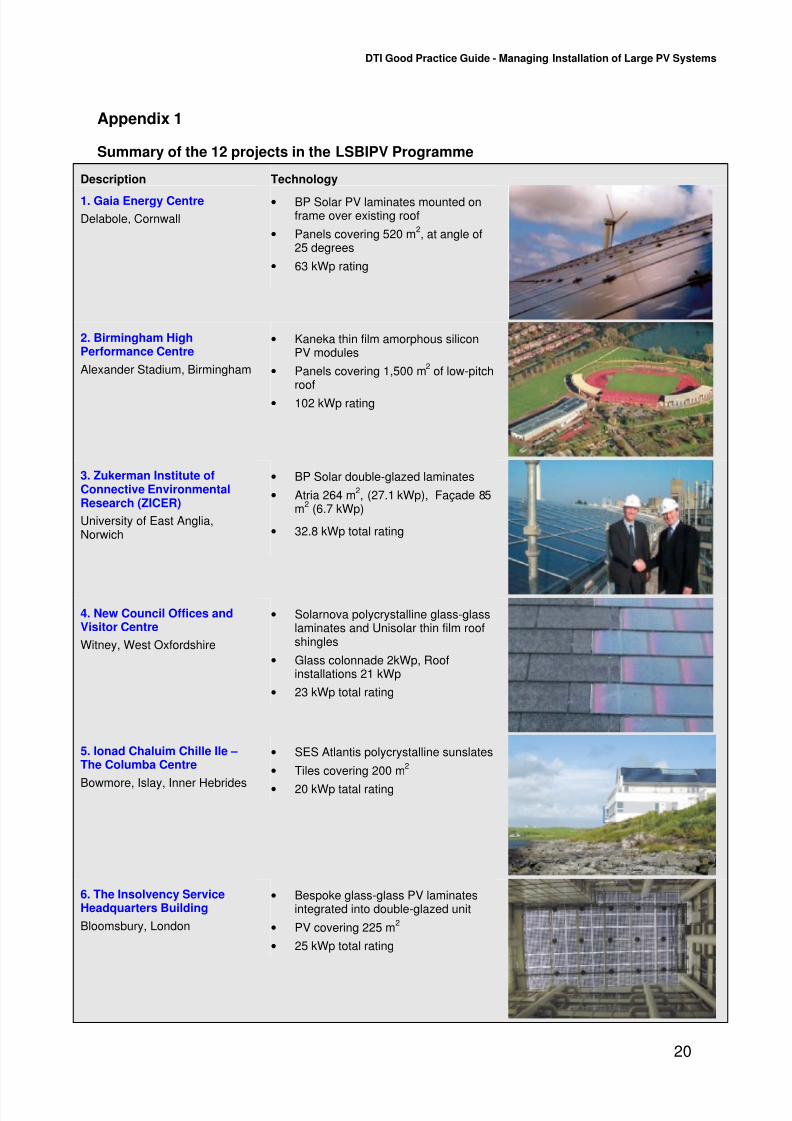
Appendix 1
Summary of the 12 projects in the LSBIPV Programme
Description Technology
1. Gaia Energy Centre
Delabole, Cornwall
• BP Solar PV laminates mounted onframe over existing roof
• Panels covering 520 m2, at angle of
25 degrees
• 63 kWp rating
2. Birmingham HighPerformance Centre
Alexander Stadium, Birmingham
• Kaneka thin film amorphous siliconPV modules
• Panels covering 1,500 m2
of low-pitchroof
• 102 kWp rating
3. Zukerman Institute ofConnective EnvironmentalResearch (ZICER)
University of East Anglia,Norwich
• BP Solar double-glazed laminates
• Atria 264 m2, (27.1 kWp), Façade 85
m2
(6.7 kWp)
• 32.8 kWp total rating
4. New Council Offices andVisitor Centre
Witney, West Oxfordshire
• Solarnova polycrystalline glass-glasslaminates and Unisolar thin film roofshingles
• Glass colonnade 2kWp, Roofinstallations 21 kWp
• 23 kWp total rating
5. Ionad Chaluim Chille Ile –The Columba Centre
Bowmore, Islay, Inner Hebrides
• SES Atlantis polycrystalline sunslates
• Tiles covering 200 m2
• 20 kWp tatal rating
6. The Insolvency ServiceHeadquarters Building
Bloomsbury, London
• Bespoke glass-glass PV laminatesintegrated into double-glazed unit
• PV covering 225 m2
• 25 kWp total rating

7/28/2019 Good Practice Guide Managing Installation of PV Systems
http://slidepdf.com/reader/full/good-practice-guide-managing-installation-of-pv-systems 22/28
DTI Good Practice Guide - Managing Installation of Large PV Systems
21
Description Technology
7. St Mary’s CommunityChurch Hall
Osterley, London
• BP Solar monocrystalline PVmodules
• PV covering 219 m2
• 30 kWp total rating
8. Cotswold Water ParkGateway Centre
Gloucestershire
• BP Solar BP585S monocrystallinemodules
• PV covering 380 m2
• 51 kWp total rating
9. Belfast Education andLibrary Board (BELB) PrimarySchool
Cavehill Road, Belfast
• BP Solar BP585DL monocrystallinemodules and Solarnova glass/glasslaminates
• 46.5 kWp total rating
10. Sports Science Building,University of Gloucestershire
Oxstalls Campus, Gloucester
• Photowatt PW1650 polycrystallinemodules
• PV covering 492 m2
• 65.45 kWp total rating
11. Welsh DevelopmentAuthority OpTIC Technium
St Asaph, Clywd, North Wales
• Shell ST36 CIS modules
• PV covering 1000 m2
• 85 kWp total rating
12. Barnstaple Civic Centre
Barnstaple, North Devon
• BP Solar BP5170 monocrystallinemodules
• 56.6 kWp total rating

7/28/2019 Good Practice Guide Managing Installation of PV Systems
http://slidepdf.com/reader/full/good-practice-guide-managing-installation-of-pv-systems 23/28
DTI Good Practice Guide - Managing Installation of Large PV Systems
22
Appendix 2
Table of Key Documents for PV
Title Front Cover Notes
Photovoltaics in BuildingsGuide to the installation of PVsystems2
ndedition
The main ‘best practice guide for PV,with references to many of thedocuments below.
Engineering RecommendationG59/1‘Recommendations for theconnection of EmbeddedGenerating Plant to the RegionalElectricity Companies’ Distribution
Systems’, (Electricity Association,1991),www.energynetworks.org/dg01.asp
Note: This is the Electricity IndustryRecommendation for connection ofgenerators. It is applicable if theinverter is not covered under G83/1.Other guidance can be found in IEC61727 Ed.2: Photovoltaic (PV)
systems - Characteristics of theutility interface.
Engineering RecommendationG83/1 Sept 2003, ‘Recommendations forthe connection of Small-scaleEmbedded Generators (up to 16Aper phase) in parallel with PublicLow-Voltage Distribution Networks’,(Energy Networks Association, 2003),www.energynetworks.org/dg01.asp
Note: This simplified connection route
applies to ‘type tested’ inverters forsystems up to about 5kWp. Prior-notification of the Distribution NetworkOperator (DNO) is not required for‘single’ installations, but is required for‘multiple’ single phase installations.
It refers to the Electricity Safety,Quality and Continuity Regulations(ESQCR), 2002. Draft prEN 50438‘Requirements for the connection ofmicro-cogenerators in parallel withpublic low-voltage distributionnetworks’ is a European version,which once issued, will also cover
systems up to 16A per phase.

7/28/2019 Good Practice Guide Managing Installation of PV Systems
http://slidepdf.com/reader/full/good-practice-guide-managing-installation-of-pv-systems 24/28
DTI Good Practice Guide - Managing Installation of Large PV Systems
23
PPS22‘Planning Policy Statement 22:Renewable Energy, ISBN 0 11753924 4, 2004,www.odpm.gov.uk/index.asp?id=1143908
Also see ‘Planning for RenewableEnergy; A companion Guide toPPS22’, which provides additionalguidance for PV in Technical Annex 6Active Solar (Photovoltaics), ISBN 185112 7542.
Note: UK Planning Consent (ifrequired). PPS22 replaces UKPlanning Policy Guidance note(PPG)22. It sets out the Government'splanning policies for renewable energy,which planning authorities should have
regard to when preparing localdevelopment documents and whentaking planning decisions.
Building Control Approval,www.odpm.gov.uk/index.asp?id=1130474,www.labc-services.co.uk/buildingregs/default.asp
Note: For ‘integrated products’ in theUK where the PV forms part of thebuilding envelope (eg PV roof tiles),proof of compliance with relevantBuilding Regulations may be requiredby the local Building Control Inspector,eg compliance to:
• Fire resistance standards (egBS476- part 3)
• Relevant wind uplift andweatherproofing standards (egBS6399, BS5534). See also BRE
Digest 489 & 495 below whichare specific to PV.
BS7671: 2001 ‘Requirements forElectrical Installations, IEEWiring Regulations’Sixteenth Edition (incorporatingAmendments), ISBN: 0 86341 373 0,www.iee.org/publish/books/WireAssoc

7/28/2019 Good Practice Guide Managing Installation of PV Systems
http://slidepdf.com/reader/full/good-practice-guide-managing-installation-of-pv-systems 25/28
DTI Good Practice Guide - Managing Installation of Large PV Systems
24
IEE Guidance Note 7 - SpecialLocations(2nd Edition), ISBN 0 85296 995 3,www.iee.org/publish/books/WireAssoc
Note: IEE Guidance Note 7 - SpecialLocations, Chapter 12 covers ‘Solarphotovoltaic (PV) power supplysystems’ as a ‘special location’ asdefined in IEE Regs. The guidance isbased on IEC 60364-7-712:
‘Requirements for specialinstallations or locations – Solarphotovoltaic (PV) power systems’.
Part P (Electrical safety) -Building Regulations www.odpm.gov.uk/index.asp?id=1130906
Note: From 1st January 2005, peopleundertaking electrical work in homesand gardens in England and Waleshave had to follow new rules inBuilding Regulations. Virtually alldomestic PV installations will fall underthe scope of Part P.
There are two routes to comply withthe requirements of Part P:
– Notify the relevant Building Controldepartment before starting thework
– The contractor registers under aCompetent Person Scheme (asapproved by the office of thedeputy prime minister)
Note: An electronic version of the formis available at the Local AuthorityBuilding Control (LABC) websitewww.link2content.co.uk/uploads/buildingnotice%202005%20unprotected(1).doc, and it can be submitted using their‘Submit-a-Plan’ scheme www.labc-services.co.uk/buildingregs/default.asp.
BRE Digest 489
– ‘Wind loads on roof-basedphotovoltaic systems’, ISBN 1 86081713 0, 2004, www.brebookshop.com
Note: This Digest reviews the windloading information appropriate forroof-based PV systems and givesrecommendations and guidance for thedesign of roof-based PV systems for
wind loads. It covers both PV tiles orslates integrated into pitched roofs andPV modules mounted on or abovepitched roofs.

7/28/2019 Good Practice Guide Managing Installation of PV Systems
http://slidepdf.com/reader/full/good-practice-guide-managing-installation-of-pv-systems 26/28
DTI Good Practice Guide - Managing Installation of Large PV Systems
25
BRE Digest 495
Mechanical installation of roof-mounted photovoltaic systems
ISBN 1 86081 869 23, 2005,www.brebookshop.com
Note: This Digest gives guidance oninstalling and using photovoltaicsystems on roofs. The guidance refersonly to the mechanical installation ofroof mounted integrated and stand-offphotovoltaic systems; it provides best
practice guidance on installationrequirements and does not constitutefixing instructions.
‘Photovoltaics in Buildings–Safety and the CDM Regulations’
(BSRIA/DTI Feb 2000, ISBN 0 86022548 8),www.bsria.co.uk/bookshop/system/index.html
This covers larger systems, althoughmost of the safety advice is alsorelevant to small installations that maybe exempt from the Regulations.
It provides a simple guide to the
Construction Design andManagement Regulations 1994(CDM Regulations), with regard to thedesign, installation, operation,maintenance, decommissioning anddisposal of PV installations inbuildings.
Note: It also provides a commentaryon the UK legislative framework withparticular reference to CDMRegulations, hazards and risksassociated with PV installations, andPV issues that must be addressed inthe Health and Safety Plan andHealth and Safety File.
Draft IEC 62446 Ed.1 ‘Grid connected PV systems –Minimum system documentation,commissioning tests and inspection
requirements’.
Note: This standard will define theminimum information anddocumentation required to be handedover to a customer following the
installation of a grid connected PVsystem. This document also describesthe minimum commissioning tests,inspection criteria and documentationexpected to verify the safe installationand correct operation of the system.This document is not written for ACmodule systems or systems that utilizeenergy storage (e.g. batteries) orhybrid systems.
7/28/2019 Good Practice Guide Managing Installation of PV Systems
http://slidepdf.com/reader/full/good-practice-guide-managing-installation-of-pv-systems 27/28
DTI Good Practice Guide - Managing Installation of Large PV Systems
26
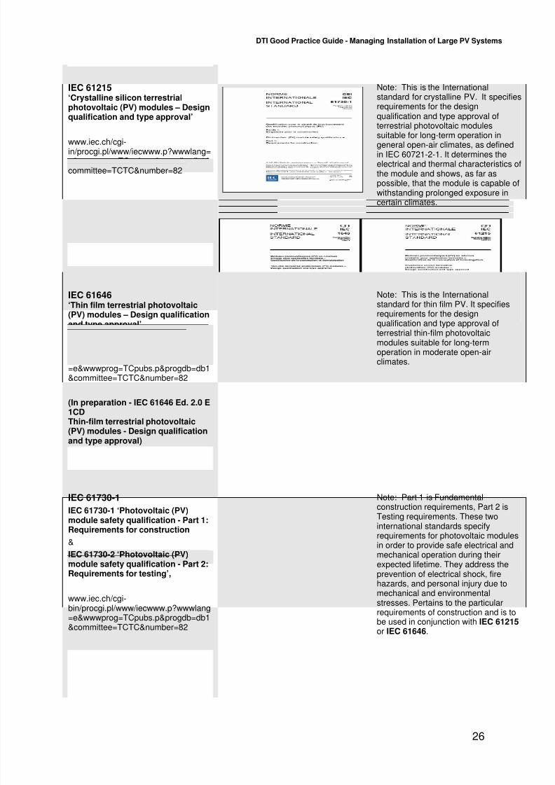
IEC 61215‘Crystalline silicon terrestrialphotovoltaic (PV) modules – Designqualification and type approval’
www.iec.ch/cgi-in/procgi.pl/www/iecwww.p?wwwlang=e&wwwprog=TCpubs.p&progdb=db1&committee=TCTC&number=82
Note: This is the Internationalstandard for crystalline PV. It specifiesrequirements for the designqualification and type approval ofterrestrial photovoltaic modules
suitable for long-term operation ingeneral open-air climates, as definedin IEC 60721-2-1. It determines theelectrical and thermal characteristics ofthe module and shows, as far aspossible, that the module is capable ofwithstanding prolonged exposure incertain climates.
IEC 61646‘Thin film terrestrial photovoltaic(PV) modules – Design qualificationand type approval’
www.iec.ch/cgi-bin/procgi.pl/www/iecwww.p?wwwlang=e&wwwprog=TCpubs.p&progdb=db1&committee=TCTC&number=82
(In preparation - IEC 61646 Ed. 2.0 E
1CDThin-film terrestrial photovoltaic(PV) modules - Design qualificationand type approval)
Note: This is the Internationalstandard for thin film PV. It specifiesrequirements for the designqualification and type approval ofterrestrial thin-film photovoltaicmodules suitable for long-termoperation in moderate open-airclimates.
IEC 61730-1
IEC 61730-1 ‘Photovoltaic (PV)module safety qualification - Part 1:Requirements for construction
&
IEC 61730-2 ‘Photovoltaic (PV)module safety qualification - Part 2:Requirements for testing’,
www.iec.ch/cgi-bin/procgi.pl/www/iecwww.p?wwwlang=e&wwwprog=TCpubs.p&progdb=db1&committee=TCTC&number=82
Note: Part 1 is Fundamentalconstruction requirements, Part 2 isTesting requirements. These twointernational standards specifyrequirements for photovoltaic modulesin order to provide safe electrical andmechanical operation during theirexpected lifetime. They address theprevention of electrical shock, firehazards, and personal injury due tomechanical and environmentalstresses. Pertains to the particularrequirements of construction and is tobe used in conjunction with IEC 61215 or IEC 61646.

7/28/2019 Good Practice Guide Managing Installation of PV Systems
http://slidepdf.com/reader/full/good-practice-guide-managing-installation-of-pv-systems 28/28
DTI Good Practice Guide - Managing Installation of Large PV Systems
Measured parameters:
• Solar radiation on the horizontal
• Solar radiation in plane of array
• Ambient temperature
• Array temperature
• DC electrical output of each PV array
• AC output of each inverter• Electricity imported to the building
• Electricity exported from the building
Energy Output from PV System
0
2000
4000
6000
8000
10000
12000
J a n - 0 5
F e b - 0 5
M a r - 0 5
A p r - 0 5
M a y - 0 5
J u n - 0 5
J u l - 0 5
A u g - 0 5
S e p - 0 5
O c t - 0 5
N o v - 0 5
D e c - 0 5
O u t p
u t k W h
Actual output
Predicted output
Example of annual processed data, comparing actual energy output with estimated output at the OpTIC Centre, North Wales
Example Wall Display – St Mary’s Church
Appendix 3
Monitoring of PV systems
Most large scale buildings with PV systems have some sort of performance monitoring. As aminimum these buildings will have a wall display mounted in a prominent location such as theentrance foyer. Wall displays typically provide the following information about the building’s PVsystem:
• Instantaneous generation from the PV system(in kW)
• Cumulative generation of PV system sincecommissioning, or cumulative daily generation(in kWh)
• Total amount of CO2 saved to date (in kg CO2)
The wall display provides information to theoccupants about their building’s PV system, andis a way of promoting the organisation as beingenvironmentally conscious.
Use of a data logger enables informationon the PV system to be stored, usually atintervals of 5 or 10 minutes. This can beused to track the performance of the PVsystem, such as providing a comparisonof the energy output over different months
as shown in the example of the OpTICCentre.
More sophisticated performance detailscan be gained from the PV system withthe appropriate monitoring equipment,such as reference cells for measuringinsolation. This can be used to determinethe efficiency of different components
within the system, or different arrays within the system, and the overall efficiency. Thisinformation enables any faults or failures within the system to be identified to maximise
generation. Under the LSBIPV programme,information has been collected on anumber of parameters as shown below toenable extensive analysis to beundertaken.