Embed Size (px)
Citation preview
Page 1 of 144
GOVERNMENT OF INDIA
EAST CENTRAL RAILWAY
TENDER DOCUMENT
FOR
OPEN TENDER
Name of the work:- “Residual works of Replacement of worn out lever frames bypanel interlocking at Mokama in Danapur ”
TENDER No. SG/W/DNR/OT/03(15-16)
(Not Transferable)Important information:
i) Approx. value of the work: Rs. 3835098.97/-ii) Cost of Tender Document: Rs. 3,000/-i) Earnest Money: Rs. 76700/- ii) Last date of Sale of Tender Document: 05/01/2016iii) Last date of Receipt of Tender offer: 06/01/2016 up to 12.00 hrs.iv) Opening of Tender: 06/01/2016 at 12.30 hrs.
M/s …………………………………………. …………………………………………. ………………………………………….
Divisional Signal &Telecom Engineer (Works)E.C.Railway, Mokama
INDEX
1. Tender Notice
2. Check List of items to be complied by the Tenderer
3. Instructions to the tenderer
4. General conditions of tender
5. General Conditions of Contract
6. Special Conditions of Contract
7. List of forms of tenders etc.
8. Annexure -A Offer letter
9. Annexure-B Guarantee bond for security deposit
10. Annexure-C Bank guarantee
11. Annexure-D Standing Indemnity bond
12. Annexure-E Statement of deviation
13. Annexure-F Proforma for the work performance guarantee
14. Annexure-G Qualification experience
15. Annexure-H Receipt certificate
16. Annexure-I Extension of period of completion of work (Contractor Account)
17. Annexure-J Extension of period of completion of work (Railway Account)
18. Annexure-K Modification to GCC & Standard Specification.
19. Annexure-L Acknowledgement for receiving materials and cables from Railway
20. Annexure-M Sources for specifications/Drawings
21. Annexure-N Name of work/Nature of work
22 Annexure-O Rroute survey for OFC / 6 quad telecom cable
23 Annexure-P Laying and jointing of OFC / 6 quad telecom cable
22. Annexure-Q Optic Fibre Cable communication system
23 Annexure-S Technical supplement (specification of materials and tools & plants)
24. Annexure-T Guidelines to the Tenderer
25. Annexure-U General spec. and Railway requirements
26. Annexure-Y Schedule – D
27. Annexure –Z (a) Summary (b) SOR (c) Non SOR (d) Non Schedule items.
Page 2 of 144

EAST CENTRAL RAILWAY
Open tender notice no.: 03 of 2015
OPEN TENDER NOTICE
1.0 Sealed tenders are invited for and on behalf of president of India from competent andexperienced contractors for execution of the under mentioned work on the followingsection.
Sl. Section /Station
Date ofcommencemen
t of sale oftender
document
Closing dateof sale of
tenderdocument
Last dateand time of
receipt of thetender
Date andtime of
opening ofthe tender
Completion periodof work
1 2 3 4 5 6 7
1.
“Residual works of Replacement of worn out lever frames by panel interlocking at Mokama in Danapur ”
05/12/2015 05/01/201606/01/2016
up to 12.00 hrs.
06/01/2016at
12:30 hrs.
12Months
i) Approximate cost of work Rs. 3835098.97/- (Rs. Thirty Eight Lakhs Thirty Five Thousand Ninty Eightand Ninty Seven paise only.)ii) Earnest money Rs. 76700/- (Rs. Seventy Six thousand Seven Hundred only) to be deposited in favourof FA & CAO/East Central Railway / HAJIPUR.iii) Validity of offer and earnest money should be 180 days from the date of opening of tender.
1.1 Non transferable tender documents may be purchased from the office of Chief Signal &Telecom Engineer, East Central Railway, Hajipur and Dy. Chief Signal & TelecomEngineer (Works), DRM Building East Central Railway, Danapur 801105, by thetenderers fulfilling the following conditions on payment of non-refundable amount ofRs. 3,000/- (Rs. Ten thousand only) per copy or Rs. 3,500/- (Rs. Ten thousand fivehundred only) if required by post. The amount may be deposited in cash to DivisionalCashier, Sonepur/Danapur or through A/c payee demand draft drawn on anynationalized bank in favour of FA & CAO/ East Central Railway / Hajipur and payable atHajipur quoting the details of the above tender.
1.2 Tender can be dropped in prescribed tender box placed in the office of the Chief Signal &Telecom Engineer, East Central Railway at Hajipur or in the office of the Dy. ChiefSignal & Telecom Engineer (Works), East Central Railway, Danapur.
1.3 If the office is closed on the stipulated date and time due to some unforeseen reason, thetender will be received and opened on the next working day at the same time as thecase may be.
1.4 Tender document down loaded from the website www.ecr.indianrailways.gov.in will beconsidered valid only when submitted along with cost of tender document submitted inthe form of money receipt issued by Divisional Cashier, Sonepur/Danapur or throughA/c payee demand draft drawn on any nationalized bank in favour of FA & CAO/EastCentral Railway / Hajipur and payable at Danapur quoting the details of the abovetender.
Page 3 of 144

1.5 Railway administration will not be responsible for any delay / difficulties/ inaccessibility ofthe downloading facility for any reason whatsoever. In case of any discrepancybetween the tender document downloaded from the internet and the master copyavailable in the office mentioned above, later shall prevail and will be binding on thetenderer. No claim on this account will be entertained.
1.6 Tender document from the website should be printed on A-4 size paper.2.0 Brief scope of work: -
Tender No.: SG/W/DNR/OT/03(15-16)Name of work:
“Residual works of Replacement of worn out lever frames by panel interlocking atMokama in Danapur ”
3 ELIGIBILITY CRITERIA:-
The total contractual amount received by the tenderer during the last three financialyears and during current financial year should be a minimum of 150% of the advertisedtender value of the work. Audited balance sheets, duly certified by CharteredAccountant, for the last three financial years & the current financial year must besubmitted by the tenderer. If audited balance sheet is not available, contractual amountreceived, duly certified by Chartered Accountant, should be submitted as proof ofturnover. Alternatively, at least payment certificates from Central Govt./StateGovt./Central P.S.U.s & other Govt. agencies may be submitted.
Note:- Credential certificate(S) issued by Private Individuals will not be accepted.
4.0 The tenderer should submit the credential certificate, issued from an executingauthority regarding fulfillment of eligibility criterion mentioned in Para 3.1 as above.
5.0 The tenderer should submit the attested certificates from the employer/ client, auditedbalance sheet duly certified by the chartered accountant in regard to fulfillment ofeligibility criterion mentioned in Para 3.2 as above.
6.0 The tenderer must submit earnest money in favour of FA & CAO/East Central Railway /Hajipur and payable at Hajipur with the offer without which the tender shall besummarily rejected. The required earnest money should be either deposited in cashwith the Divisional Cashier, Sonepur/Danapur or be submitted in the form of DemandDraft issued by nationalized bank or in other acceptable forms as mentioned undergeneral conditions of tender in the tender document.
7.0 Non-receipt or delayed receipts of tenders due to any account shall be at tenderer’s risk.
8.0 Railway reserves its right to either cancel the tender or reject any or all the tenderswithout assigning any reasons thereof.
Divisional Signal & Telecom Engineer(Works)
East Central Railway, Mokama.
Page 4 of 144
EAST CENTRAL RAILWAY
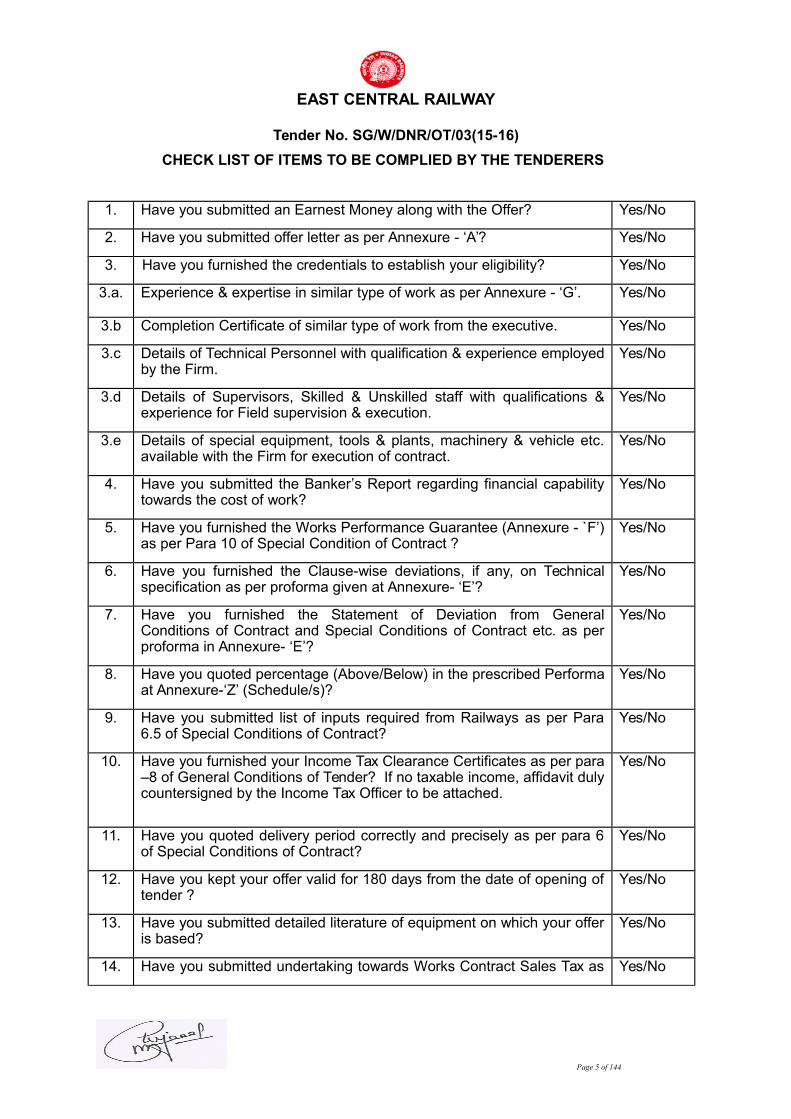
Tender No. SG/W/DNR/OT/03(15-16)
CHECK LIST OF ITEMS TO BE COMPLIED BY THE TENDERERS
1. Have you submitted an Earnest Money along with the Offer? Yes/No
2. Have you submitted offer letter as per Annexure - ‘A’? Yes/No
3. Have you furnished the credentials to establish your eligibility? Yes/No
3.a. Experience & expertise in similar type of work as per Annexure - ‘G’. Yes/No
3.b Completion Certificate of similar type of work from the executive. Yes/No
3.c Details of Technical Personnel with qualification & experience employedby the Firm.
Yes/No
3.d Details of Supervisors, Skilled & Unskilled staff with qualifications &experience for Field supervision & execution.
Yes/No
3.e Details of special equipment, tools & plants, machinery & vehicle etc.available with the Firm for execution of contract.
Yes/No
4. Have you submitted the Banker’s Report regarding financial capabilitytowards the cost of work?
Yes/No
5. Have you furnished the Works Performance Guarantee (Annexure - `F’)as per Para 10 of Special Condition of Contract ?
Yes/No
6. Have you furnished the Clause-wise deviations, if any, on Technicalspecification as per proforma given at Annexure- ‘E’?
Yes/No
7. Have you furnished the Statement of Deviation from GeneralConditions of Contract and Special Conditions of Contract etc. as perproforma in Annexure- ‘E’?
Yes/No
8. Have you quoted percentage (Above/Below) in the prescribed Performaat Annexure-‘Z’ (Schedule/s)?
Yes/No
9. Have you submitted list of inputs required from Railways as per Para6.5 of Special Conditions of Contract?
Yes/No
10. Have you furnished your Income Tax Clearance Certificates as per para–8 of General Conditions of Tender? If no taxable income, affidavit dulycountersigned by the Income Tax Officer to be attached.
Yes/No
11. Have you quoted delivery period correctly and precisely as per para 6of Special Conditions of Contract?
Yes/No
12. Have you kept your offer valid for 180 days from the date of opening oftender ?
Yes/No
13. Have you submitted detailed literature of equipment on which your offeris based?
Yes/No
14. Have you submitted undertaking towards Works Contract Sales Tax as Yes/No
Page 5 of 144
per para 11.2 of Special Conditions of Contract?
15. Partnership Deed if any, Constitution of the Firm & copies of connectedlegal documents to be attached with the offer.
Yes/No
16. Full clear Postal address for communication. Yes/No
17. If working through contract labour, the contractor must register withLabour Commissioner – necessary License to be submitted with tenderor to be produced before signing of contract agreement.
Yes/No
18. Have you furnished time schedule for supply of materials and executionof work?
Yes/No
B: CERTIFICATE BY TENDERER :
It is certified that the above check list of items have been complied.
SIGNATURE ……………………………………
Name .............................................................
Page 6 of 144
EAST CENTRAL RAILWAY
SIGNAL & TELECOMMUNICATION DEPARTMENT
INSTRUCTIONS TO TENDERER
1.0 SUBMISSION OF BIDS:
The offer complete in all respect must be sealed and marked as under: -
Name and Address of the Tenderer / Proposal from against tender No.SG/W/DNR/OT/03(15-16) to be opened at 12:30 hrs on 06/01/2016.
2.0 OPENING OF BIDS:
2.1 Tender offer of the tenderer will be opened at 12:30 hrs on 06/01/2016.Thereafter, technical discussions may be held with the tenderer wherevernecessary.In case the opening date happens to be a holiday or Bandh, the tender will beopened on the next working day at the same time.
2.2 Before submission of tender, tenderer shall satisfy himself about the localconditions, topography, the details of existing facilities and the requirement ofmatching interface unit, etc. If at any stage subsequent to submission of tender itis found that extra equipment are required to meet the tender conditions,although same may not be specially mentioned in the enclosed schedule, theseshall have to be supplied by the tenderer free of cost within the total cost of thetender.
2.3 The tenderer shall keep the offer open for a minimum period of 180 days fromthe date of opening of the tender. Within that period, the tenderer cannotwithdraw his offer subject to the period being extended further if required bymutual agreement from time to time. Any contravention of the above condition willmake the tenderer liable for forfeiture of his Earnest Money Deposit.
2.4 PARTICIPATION OF JOINT VENTURE FIRMS IN WORKS TENDER :-
Joint venture clause will be applicable to the firm as per Railway Board’s letter No.2002/CE-1/CT/37 dated 02.09.2008 with latest amendment.
2.5 The tenderer shall bear all costs associated with the preparation and submissionof the tender and the Railway will in no case be responsible or liable for thesecosts, regardless of the conduct or outcome of the bidding process.
2.6 All queries with regard to this tender shall be submitted to this office minimumseven days in advance of last date of submission of tender document failingwhich it will be presumed that there is no query from tenderer’s side.
2.7 Offer received through FAX, Cable OR Telegram / Telex and incomplete offers willbe summarily rejected.
2.8 Tenders received in the office of Chief Signal & Telecom. Engineer, East CentralRailway, Hajipur or Dy. Chief Signal & Telecommunication Engineer (Works), EastCentral Railway, Danapur after the time of scheduled closing of the tender shallbe classified as “Delayed / Late Tender” EVEN if posted by the Tenderersufficiently in time. The administration is not responsible for either the loss in the
Page 7 of 144
transit or “Late/Delayed” receipt of tender. Late/Delayed tender will be dealt withas per rules in vogue in the Railways.
2.9 Offer from tenderer not meeting the eligibility criterion will be outright rejected.
3.0 EARNEST MONEY:
3.1 Earnest Money against this tender is Rs. 76700/- (Rs. Seventy Six thousandSeven Hundred only). The Earnest Money is to be submitted as per detailsgiven in clause 6 of General Conditions of Tender.
3.2 Validity of the Earnest Money to be at least up to the validity of the offer.
4.0 PERIOD OF COMPLETION :
4.1 The work is to be completed within a period of twelve months from the date ofissue of Letter of Acceptance.
4.2 The Tenderers are required to scrutinize carefully all clauses appearing in theTender documents and to sign in token thereof on every page of the Tenderdocument.
4.3 The Tenderers should quote rates in figures and in words. Wherever there is adifference between the rates quoted in figures and in words, the rate quoted inwords will be taken as correct.
4.4 All details and drawing pertaining to the works as are available can be seen in theoffice of the Chief Signal & Telecom. Engineer, East Central Railway, Hajipur andDy.Chief Signal & Telecom. Engineer (Works), East Central Railway, Danapurduring office hours.
4.5 The cancellation of any document such as Power of Attorney, Partnership Deedetc. shall forthwith be communicated by the contractor to the Railway in writingfailing which the Railway shall have no responsibility or liability for any action onthe strength of said documents.
4.6 The contractor will be permitted to make use of the service roads already existingwithin the Railway possession. If additional service roads are required withinRailway premises the contractor may be allowed to make them at his own costwith the prior approval of the Railway’s Engineer. All service roads requiredoutside Railway boundary shall be constructed by the contractor at his own riskand cost. These roads shall be maintained by the contractor at his own cost. TheRailway reserves the right to make use of these service roads as and whennecessary without any payment to the contractor.
4.7 If original work order issued to the contractor is lost by him for any reason what-so-ever and contractor demands for supply of a duplicate of the same, penal levyof Rs.10/- (Rupees Ten only) for each work order will be imposed on him for theissue of duplicate copy of the work order.
4.8 The Tenderer/Contractor may be required to engage surplus /retrenched casuallabours of the Railway, if found suitable up to the extent as deemed fit by theRailway during the currency of the contract. The terms of employment betweensuch labour and the Tenderer/Contractor may be on mutually agreed termssubject to the statutory provisions contained in the Labour Regulations andenactments. The Contractor shall indemnify the Railway against any claim arisingout of employment of such labour and the Railway shall not be party to anydisputes etc. arising out of the employment of such labour by theTenderer/Contractor.
Page 8 of 144
4.9 When the tender is received by the Railway Administration, it will be understood thatthe tenderer/s has/have gone through carefully in details all the Instructions,Conditions, General and Special Conditions of the Contract and all otherinstructions for execution of the work and that the tenderer/s has/have gothimself/themselves clarified in all points and doubts and interpretations by theproper authorities of the Railway Administration.
5.0 STORAGE OF PETROLEUM:
5.1 No petroleum sprit within the meaning of the Indian Petroleum Act shall be stored atsite or adjacent land until the approval of the Railway and necessary licenseunder the Act has been obtained by the tenderer.
5.2 The Contractors who are working in the establishment through contract labour(Regulation and Abolition) Act 1970 and Central Rule 1971 shall obtain a licensefrom the Assistant Labour Commissioner concerned and produce the same to theRailway either along with the tender or before signing the agreement failing whichthe contract awarded will be terminated that they have not complied with the legalprovisions of the said act and Earnest Money forfeited.
5.3 Railway will not arrange for release of foreign exchange for any contract work.
5.4 This tender book is complete with Schedule.
DIVISIONAL SIGNAL & TELECOM ENGINEER(WORKS),
EAST CENTRAL RAILWAY, MOKAMAFOR AND ON BEHALF OF PRESIDENT OF INDIA
THE ABOVE INSTRUCTION TO TENDERER ARE UNDERSTOOD ANDACCEPTED BY ME/US.SIGNATURE OF THE TENDERER/S. _________________________DATE _________________________
Page 9 of 144

GENERAL CONDITIONS OF TENDER
1.0 TENDER DOCUMENT:
1.1 The intending tenderer should study Special Conditions of Contract, Instructions toTenderer, Technical Specification, Drawings, Documents, Schedules etc. enclosedand also latest General Conditions of Contract, 2010 of East Central Railway of theEngg. Department with up to date modifications and IRS Conditions of Contract forthe Stores department with up to date modifications all herein after collectivelyreferred to as Tender Specification.
Any submission of a quotation by the tenderer shall be deemed to have been doneafter careful study examination of these documents with full understanding of theimplications shall be deemed to have been accepted, unless specially commentedupon otherwise by the Tenderer in his quotation. Failure to adhere to one or all theseinstructions may render his offer liable to be rejected without any reference.
1.2 The typical drawings referred to in the tender shall be available in the office of theCSTE/ECR/Hajipur and Dy.CSTE(W)/ E.C.Rly/ Danapur. These can be seen andclarifications obtained on any working day up to the previous working day before thelast day of closing of Tender.
1.3 Provision in the General Condition of Tender and Special Conditions of the Contractin the tender documents will override any overlapping provisions of GeneralConditions of contract 2010 of East Central Railway of the Engg. Department with upto date modifications and IRS Conditions of Contract for the Stores department withup to date modifications. When there is conflict between General Conditions ofcontract 2010 of East Central Railway of the Engg. Department with up to datemodifications / IRS conditions of contract for the stores department with up to datemodifications and special conditions of the contract, the special conditions shallprevail.
2.0 OFFICIAL TENDER FORM:
2.1. Chief Signal & Telecommunication Engineer, East Central Railway, Hajipur on behalfof PRESIDENT OF INDIA, invites quotations from established, experienced andreliable contractors who have adequate experience for this type of work.
2.2. The tenderer must submit his tender in duplicate in time on the date of tendersubmission of the tender to the office of Chief Signal & Telecom Engineer, EastCentral Railway, Hajipur or in the office of Dy.Chief Signal & Telecom Engineer(Works), East Central Railway, Danapur filling in the Proforma given in form ofSchedule/s attached here to duly signed at every page and having filled in theSchedule/s in ink, stating therein percentage (Above/Below), quantities, prices, taxes& duties of the tender (both in figures and words), giving all information andparticulars asked for.
The tenderer shall submit in the same envelope of his tender a short and conciseexplanatory memorandum pertaining to his tender, if required, but suchmemorandum or any letter accompanying the tender submitted by him shall from partof tender. He may also enclose a descriptive matter for consideration.
Page 10 of 144

3.0 SCHEDULE / SCHEDULES:
3.1 The TENDERER are required to quote percentage (Above/Below) in the prescribedPerforma at Annexure-‘Z’, Part-I, Part-II & Part-III (SOR, NON-SOR & NON-Schitems) in the summary sheet of Schedule.
3.2 The rates offered against the Schedule/s will include the following elements of Costwithout fail.
(i) Cost carriage, Loading and Unloading at Inspector’s store, and transportationof all materials required to the actual site of the work i.e., place of installationand all other incidentals connected there-with excluding the materialssupplied by the Railway. For materials supplied by the Railway the executionrate should include transportation charges from the Railway Stores to the siteand collection of balance materials left over after the work, if any, and handingover to Railway Store.
(ii) All other miscellaneous expenses necessary for the execution of the work andfulfilment of the contractual obligation as per Schedule/s.
3.3 (i) The rate tendered for in the Schedule/s attached to the tender document and accepted by the Railway shall form the basis for payment forworks done/materials supplied by the contractor.
(ii) The rates quoted by the contractor shall take into account the difficulties anddelays encountered in course of work and nothing extra on these accountshall be paid for.
3.4 If any departure or substitution from the particular specification is involved, thisshould be clearly indicated in the offer giving full details of deviations. If the offer is inaccordance with the stipulated specification, “NO DEVIATION” should be clearlystated. Quotation not complete in this respect are likely to be summarily rejected. If aparticular point in the specification is not clear, the same should be got clarifiedbefore submitting the quotations. No price alteration will be permitted after opening ofthe tender on grounds of the Technical requirement not having been properlyunderstood in the first instance by the suppliers.
3.5 Each page of the offer must be numbered consecutively bear the tender number andshould be signed by the Tenderer in Ink. Reference to total number of pagescomprising the offer for each item must be made at the top of the right hand corner.
3.6 Tenderer must ensure that the conditions laid down for submission of offer arecompletely and correctly fulfilled.
3.7 All rates quoted in the tender shall be deemed to be inclusive of all Taxes, state entrytax, service tax Inspections Charges, Royalty etc. payable by the Contractor to theGovernment or any public body and normally no additional rate will be paid or claimsentertained on this account by the Railway.
3.8 Other Local Taxes levied either by Governmental agency or by Municipal agencyshall not be paid by the Railway. These are deemed to be included in the F.O.R.price, unless specifically brought out in the offer.
Page 11 of 144

3.9 Tender forms containing over writings, erased rates not shown in words are liable tobe rejected. In case of discrepancy in rates as shown in figures and in words if noticethe accepting authority may at his discretion accept the lower of the two.
3.11 SCHEDULE COVERING DELIVERY OF MATERIALS AND THE EXECUTION OFTHE WORK AT SITE :
(i) The tenderer shall attach to his offer a time schedule showing the guaranteedtime schedule for the supply of materials, the progress and completion of the works at site.
(ii) The time Schedule shall be as referred to the Instruction to tenderer.
4.0 ERASURE OR ALTERATION:
4.1 No erasure or alteration in the text of the tender papers to be submitted by thetenderer is permitted and any such erasure and/or alteration will either bedisregarded or render the whole Tender void at the option of the Railway. Anycorrection by the tenderer in his entries must be attested by him.
5.0 GENERAL REQUIREMENT:
(a) All documents to be submitted in connection with this tender will be written in English.
(b) Dimensions, weights etc. shall be in Metric System/British StandardEquivalents.
(c) The technical terms and symbols to be used will be as per General andSubsidiary Rules/Signal Engineering Manual/Extant Practice of East CentralRailway.
6.0 EARNEST MONEY:
6.1. (a)The tenderer shall be required to deposit earnest money with the tender for the dueperformance with the stipulation to keep the offer open till such date as specified inthe tender under the conditions of tender. The earnest money shall be as under:-
Value of the work EMDA For works estimated to cost up to
Rs. 1 crore2% of the estimated cost of the work.
B For works estimated to costmore than Rs.1 crore.
Rs. 2 lakhs plus ½% (half percent) of theexcess of the estimated cost of workbeyond Rs.1 crore subject to a maximumof Rs. 1 crore.
The earnest money shall be rounded to the nearest Rs.10/-. This earnest money shallbe applicable for all modes of tendering.
6.1. (b) It shall be understood that the tender documents have been sold/issued to thetenderer and the tenderer is permitted to tender in consideration of stipulation on his
Page 12 of 144

part, that after submitting his tender he will not resile from his offer or modify theterms and conditions thereof in a manner not acceptable to the engineer. Should thetenderer fail to observe or comply with the said stipulation, the aforesaid amount shallbe liable to be forfeited to the Railway.
6.1. (c) If his tender is accepted this earnest money mentioned in Sub Clause 6.1.(a) abovewill be retained as part security for the due and faithful fulfillment of the contract interms of clause 16(1) of the GCC. The earnest money of other tenderers, shall, saveas herein before provided, be returned to them, but the Railway shall not beresponsible for any loss or depreciation that may happen thereto while in theirpossession, nor be liable to pay interest thereon.
6.2.a The earnest money should be in cash or in any of the following forms: -
“The Earnest Money should be in cash or in the form of deposit receipts, pay ordersor demand drafts executed by State Bank of India or any of the Nationalized Banks orby a Scheduled Bank.”
6.3 The Earnest Money furnished in accordance with para 6.1 above shall be forfeited bythe tenderer if the tenderer unilaterally withdraws or amends to or impairs/derogatesfrom the tender in any respect within the period of validity of his offer to be countedfrom the time of opening of the tender.
6.4 The Earnest Money will be refunded to the unsuccessful Tenderer afterFinalization /Cancellation or Expiry of offer validity. No Interest will be paid on theEarnest Money.
7.0 COMMENCEMENT & COMPLETION DATES:
7.1 The Contract covered by this Tender shall be deemed to commence from the Date ofIssue of Letter of Acceptance.
7.2 The work should be completed within twelve months from the date of issue of letter ofacceptance.
7.3 The Tenderer must submit a BAR CHART in their tender offer indicating the timeperiod by which the inspection and supply of materials will be completed. TheTenderer must also indicate in their BAR CHART, the completion period of variousactivities like Cable Laying, Location/Hut Erection, installation and wiring of telecomequipments such as PD MUX and STM etc and installation oand wiring ofEmergency Sockets, Testing and Commissioning.
7.4 After Contract Agreement is signed the Contractor shall furnish during the first week ofevery month a progress report showing the materials and the equipments received atsite and the progress of work carried out at site during the preceding month to theexecutive officer and to Dy. CSTE (W) /ECR, Danapur, for reviewing the work, failingwhich action will be taken as per General Condition of Contract 2010 of East CentralRailway of Engineering department with up to date modifications.
8.0 INCOME TAX CLEARANCE CERTIFICATE:
8.1 Unless otherwise exempted, the tenderer shall enclose with his tender, a valid IndianIncome Tax Clearance Certificate is prescribed from issued by the appropriate
Page 13 of 144
Income Tax Officer under the seal, which will be returned when done with, withoutwhich the Tender is liable to be rejected. In Case of a New Firm, or Firms, whichhave a taxable Income, sworn affidavit to that effect, duly Countersigned by theIncome Tax Officer shall be furnished.
9.0. CONSTITUTION OF FIRM, SIGNING OF TENDER AND ADDRESS:
9.1 The Tenderer shall clearly specify whether the Tender is submitted on his own behalfor on behalf of a partnership firm. If the Tender is submitted on behalf of apartnership concern, he should submit a certified copy of the partnership agreementwith the Tender as well as an authorization to sign the Tender documents on behalfof the partnership concern. If these documents are not enclosed along with the tenderdocument, the tender will be treated as having been submitted by an individualsigning the Tender documents and the Railway will not be bound by any power ofattorney granted by the Tenderer by changes in the composition of thepartnership firm made subsequent to submission of the Tender. It may howeverrecognise such a power of attorney and changes after obtaining appropriate legaladvice, the cost of which will be chargeable to the Tenderer.
10.0 ADVICE OF CANCELLATION OF DOCUMENTS BY TENDERER :
10.1 The Cancellation of any document such as Power of Attorney/Partnership deed etc.should be forthwith communicated by the contractor to the Rly. Administration inwriting failing which the Rly. Administration shall have no responsibility or liability foran action taken on the strength of the said document.
10.2 Any individual/s signing the tender or other documents Connected therewithshould specify whether he is signing:-(a) As sole proprietor of the concern or his attorney;
(b) As a Partner or Partners of the Firm ;
(c) For the Firm per procure, or
(d) As a Director, Manager or Secretary in the case of a Limited Company.
10.3 In the Case of a Firm not registered under the Indian partnership Act, all the partners,or the attorney duly authorized by all of them should sign the tender and all otherconnected documents.
10.4 The Original Documents empowering the individual or individuals to sign should befurnished to the Purchaser for Verification if required.
10.5 The Tenderer whose tender is accepted shall be required to appear in the office ofthe Dy. Chief Signal & Telecom Engineer (Works)/ East Central Railway, Danapur toexecute the Contract Agreement as stipulated in the Special Conditions of theContract. In case of a Firm or Corporation or authorized representative along withpower of attorney, can appear for this purpose.
10.6 In the event of any Tenderer whose Tender either in part or in full is accepted refusesto execute the contract documents, the Railway may determine that such Tendererhas abandoned the contract and thereupon his Tender and the acceptance thereofshall be null and void and the Railway shall be entitled to forfeit the Earnest Money
Page 14 of 144
as liquidated damages for such default without prejudice to any other right orremedies open to the Railway.
10.7 The Tenderer shall state in the Tender, his Postal Address fully & clearly. AnyCommunication sent to the Tenderer by post (Regd. AD) at his said address, shall bedeemed to have reached him timely, not withstanding the fact that the communicationcould not reach the tenderer at all or in time because of any inaccuracy or defect inthe said address.
11.0 PREVIOUS EXPERIENCE & DECLARATION OF CREDENTIALS:
11.1 The Tenderer should submit the following along with his bid :
(i) Details of similar jobs completed during the last three years along with briefdescription of work, organization for whom executed, approximate value ofthe contract at the time of award, date of award and date of schedulecompletion of work, date of actual start, actual completion, reason for delay, ifany, and final value of contract, as per Performa given in Annexure ‘G’. List ofpersonnel, Organization available on hand and proposed to be engaged forthe subject work. Qualification criterion as specified in tender notice in respectof the work with values required to be completed will be applicable.
(ii) List of works on hand indicating description of work, contract value,approximate value of balance work yet to be done and date of award.
(iii) Performance certificate from the clients for similar works.
(iv) Particulars of consultants to assist the company in the work, if any and list ofPlant and Machinery available on hand (Own) and proposed to inducted (Ownand hired to be given separately) for the subject work.
(v) List of Plant and Machinery available on hand (Own) and proposed toinducted (Own and hired to be given separately) for the subject work.
(vi) Document giving details of total contract amount received during the lastthree years.
Note: (a) In case of item (i) and (ii) above, supportive documents/certificates from theorganizations with whom they worked/are working should be enclosed.
(b) Certificates from private individuals for whom such works areexecuted/being executed should not be accepted.
11.2 Have minimum construction machinery, tools & plants and vehicles etc. required forsatisfactory execution of works. Details to be submitted along with bid.
11.3 The Tenderer shall not scribble or stipulate any special condition in the Tenderdocuments. Special condition, if any, may be indicated in a separate covering letter.
12.0 THE RAILWAY NOT BOUND TO ACCEPT ANY TENDER:
The Railway shall not be bound to accept the Lowest or any Tender or to assign anyreason for non-acceptance or rejection of a Tender. No Tender shall be deemed tohave been accepted unless such acceptance shall have been notified in writing to the
Page 15 of 144

successful tenderer by the Railway. The Railway reserves the right to accept anytender in respect of the whole or any portion of the work specified in the tender or todivide or reduce the work or to accept any tender for less than the tendered quantitywithout assigning any reason whatsoever.
13.0 SECURITY DEPOSIT:
13.1 The earnest money deposited by the contractor with his tender will be retained by theRailways as part of security for the due and faithful fulfillment of the contract by thecontractor. The balance to make up the security deposit, the rates for which are givenbelow, may be deposited by the contractor in cash or may be recovered bypercentage deduction from the contractor’s “on account” bills. Provided also that incase of defaulting contractor the Railway may retain any amount due for payment tothe contractor on the pending “on account bills” so that the amounts so retained maynot exceed 10% of the total value of the contract.
13.2 Unless otherwise specified in the special conditions, if any, the security deposit/ rateof recovery/mode of recovery shall be as under: -
13.2.(a) Security Deposit for each work should be 5% of the contract value.
13.2.(b) The rate of recovery should be at the rate of 10% of the bill amount till the fullsecurity deposit is recovered.
13.2.(c) Security Deposits will be recovered only from the running bills of the contract and noother mode of collecting SD such as SD in the form of instruments like BG (exceptNote (ii) below); FD etc. shall be accepted towards security deposit.Security Deposit shall be returned to the contractor after the expiry of themaintenance period in all the cases other than Note (i) mentioned below and afterpassing the final bill based on No Claim Certificate with the approval of theCompetent Authority. The Competent Authority shall normally be the authority who iscompetent to sign the contract. If this competent authority is of the rank lower than JAGrade, then a JA Grade officer (concerned with the work) should issue the certificate.The certificate, inter alia, should mention that the work has been completed in allrespects and that all the contractual obligations have been fulfilled by the contractorsand that there is no due from the contractor to Railways against the contractconcerned. Before releasing the SD, an unconditional and unequivocal no claimcertificate from the contractor concerned should be obtained.The maintenance period for this contract will be one year from the date of physicalcompletion of the work.
Note:-i) After the work is physically completed, security deposit recovered from the running
bills of a contractor can be returned to him if he so desires, in lieu of FDR/irrevocableBank Guarantee for equivalent amount to be submitted by him.
ii) In case of contracts of value Rs.50 crore and above, irrevocable Bank Guarantee canalso be accepted as a mode of obtaining security deposit.
13.3 No interest will be payable upon the earnest money and security deposit or amounts
payable to the contractor under the contract but Government Securities deposited interms of Sub-Clause 13.1 of this clause will be payable with interest accrued thereon.
14.0 TENDER AND AGREEMENT:
Page 16 of 144
The Tender shall remain open of acceptance by the Railway for the period specifiedin the tenders from the date on which tenders are opened and during which periodthe tenderer shall not withdraw offer, nor amend, impair or derogate there from.Every tenderer shall be deemed to have agreed as aforesaid in consideration of histender being considered by the Railway. If the Tenderer is notified in writing at hisaddress given in tender, within the said period that his tender whether in whole or inpart has been accepted by the Railway, he shall be bound by the terms of agreementconstituted by his tender in respect of any part of the work specified in the tenderdocument.
15.0 DETAILS CONFIDENTIAL:
15.1 The Tenderer (Whether his tender be accepted or not) shall treat the contents of thetender paper as private and confidential.
16.0 CANVASSING AND BRIBERY:
16.1 No Tenderer shall canvass any Government Official or Railway’s Engineer withrespect to his or any other tender. Contravention of this condition will involve rejectionof the tender. This clause shall not be deemed to prevent the Tenderer fromsupplying the Railway any information asked for from him.
16.2 Any bribe, commission, gift or advantage given, promised or offered by or on behalfof the contractor or his partner, agent or servant or any one on his or their behalf, toany officer, servant, representative or agent or the Railway of any person on his ortheir behalf, in relation to obtaining or to execution of this or any other contract withthe Railway shall in addition to the Criminal Liability he/they may incur under theprevention of corruption act, 1908, subject the contractor to cancellation of this andother contracts, and also to payment of any loss resulting from any such cancellation,and the Railway shall be entitled to deduct the amount so payable, from any moneyand Railway’s decision shall be final and conclusive in the matter.
17.0 EXECUTION OF CONTRACT AGREEMENT:
17.1 Any tenderer whose tender the Railway elects to accept, shall after having beenadvised by the Railway through Letter of Acceptance, be bound to execute andagreement based on accepted rates and conditions in such form as the Railway mayprescribe and lodge the same with the Railway together with the conditions ofcontract, specification and schedules referred to herein duly completed within theperiod as specified in the Letter of Acceptance.
17.2 Failure on the part of the tenderer to execute the agreement within the time as statedherein before will constitute breach of contract and the contractor’s earnestmoney/security deposit shall be liable to forfeiture.
Page 17 of 144
GENERAL CONDITIONS OF CONTRACT
The general condition of the contract (GCC) shall be asper general condition of contract 2010 of East Central Railwayof engineering department with latest amendment.
Page 18 of 144
SPECIAL CONDITIONS OF CONTRACT
1.0 GENERAL :
The following Special Condition shall apply to contractor for supply of plant andmachinery and manufactured equipment and for services in connection withTransportation, Installation, commissioning. But where they differ from the GeneralConditions of Contract the Special conditions shall over-ride the General Conditionsof Contract.
1.1 The tenderer’s attention is drawn to the fact that major deviations to any Clauseshall not be permissible.
2.0 SCOPE OF THE WORK: As given in Annexure-U
3.0 SPECIFICATIONS AND DRAWINGS:
3.1 Specifications, drawings, requisites and requirements referred to in the body of thesespecifications from an essential part thereof. The drawings and specificationsreferred to in this tender where not included can be obtained, from the sources asindicated in Annexure ‘M’.
3.2 After the contract is awarded, the Railway shall furnish to the contractor free ofcharge, a reasonable number of prints of Railway’s approved Drawings that from anessential part of this specification.
4.0 CONTRACTOR’S DRAWINGS:
4.1 The tenderer shall furnish after award of tender:
1) Drawings as well as full details for the apparatus he proposes the supplywhich are not covered by the Railway.
2) Two Copies of typical circuits diagrams with a write up that the tendererproposes to adopt, in English or as per practice already accepted on EastCentral Railway in similar contracts.
3) Two Copies of each of the drawings showing construction particulars, powerconnections and an outline of the power supply requirements with thedistribution scheme together with explanatory notes, in English.
4) Two Copies of cable requirement chart/figure along with its basis. Cable shallbe calculated with additional length required to be provided at joints, crossingetc. as per technical specification.
4.2 Contractor shall be solely responsible for ensuring that the end requirements areincorporated in all designs and drawings furnished by him. Although the drawing,designs may have been approved by the Railway, it shall be the responsibility of thecontractor to ensure the end requirement of the system.
4.3 Any work done by the contractor prior to the approval of the contractor’s drawingwill be done at the Contractor’s risk, unless previously authorised specificallyin writing in each individual case by an authorised representative of the Railway.
Page 19 of 144
4.4 No Change shall be made in any approved drawing without written consent of theRailway.
4.5 For the approval of the Railway the contractor shall furnish to the Railway correctedtracing of the drawings furnished by him along with five copies of such correcteddrawings.
4.6 After the completion of the work the following drawings, in addition to the otherdrawing mentioned elsewhere, should be supplied to the Railways in six copies.
i) System design which will include detailed Technical Literature of Equipments,Components & Parts thereof.
ii) Cable Route Diagram with position of Joints, Location Huts and Cabins etc.indicated. Users and maintenance Guide/Manual.
iii) Wiring Diagram of Equipment/Components/Modules/Parts.
4.7 Wiring Diagrams and other Plans shall be uniform in size and the size shall bepreferably to an overall Dimension of A3 size.
4.8 If the contractor shall have any doubt as to the meaning of any portion of theconditions of the specifications, drawings, or plans, he shall (before submitting thetender) set forth the particulars thereof and submit them to the Purchaser in writing,in order that any such doubt may be removed.
4.9 The contractor shall be responsible for and shall pay for any alterations of the worksdue to any discrepancies, errors or omissions in the drawings or other particulars,whether they have been approved by the Purchaser or not, provided that suchdiscrepancies, errors or omissions are not due to inaccurate information orparticulars furnished to the contractor on behalf of the Purchaser. If any, dimensionsfigured upon a drawing or plan differ from those obtained by scaling the drawing orplan, the dimensions as figured upon the drawing or plan shall be taken as correct.
4.10 After completion of the work the contractor should arrange and submit detailedcompletion drawings specified in Para above as approved by Railways in 1+6 copiesincluding polyester sheet as original.
5.0 EQUIPMENT AND SERVICES TO BE OFFERED:
5.1 In order to enable the Signalling/Telecommunication system to be brought intoposition the equipment for the entire system as in this tender are required to beprovided by the TENDERER as per the Rate Schedule at Annexure-‘Z’. The detailedscope of the work is as per the schedule at Annexure-‘Z’ (Schedule/s) read inconjunction with the Technical Specification and drawing.
In case in the Specifications, Brand Names/Model No. of a single manufacturer havebeen given, equivalent models from other reputed and standard sources are alsoacceptable if already in use in the S&T department of Indian Railways for similarpurposes except where specifically a particular uniform make/brand has been givenfor convenience of maintenance. Full technical details and pamphlets are required tobe furnished along with the comparative technical features in juxtapositions to provethe technical equivalence. This shall be submitted without fail along with the offer, asalso documentary proof that the equivalent item being quoted is satisfactorily in use.Where the brand names of 2 or 3 manufacturers have been given, the offer shall befrom amongst one of those given in the specifications. Where Batteries, BatteryChargers, Voltage Stabilizers, Wiring Materials, Cables etc. have been included inthe tender of various capacities such items of different capacities shall be from only
Page 20 of 144
one source/manufacturer unless specifically permitted in the tender otherwise. This isto ensure uniformity in maintenance, to facilitate procurement of spares and fortraining of technicians, and for keeping record of failure of equipment of eachmanufacturer during the life of the assets. This clause is mandatory.
5.2 The complete Circuit Diagram, Instruction Manual, Maintenance Manual of all theElectrical Equipment and accessories such as Power Supply Panel, BatteryChargers, UPS, D.G. set, Voltage Stabilizers etc. as applicable for execution of theproject shall accompany the offer.
5.3 The TENDERER are required to quote percentage (Above/Below) in the prescribedPerforma at Annexure-‘Z’, Part-I, Part-II & Part-III (SOR, NON-SOR & NON-Schitems) in the summary sheet of Schedule.
6.0 TIME SCHEDULE:
6.1 The time for completion of the entire work is of utmost importance. The completesystem at all stations is required to be fully operational within specified months fromthe date of issue of Letter of Acceptance. Tenderer is required to provide adequatedetail of the activities involved, to substantiate their claim of being able to meet theabove dead line for handing over the system to the Railways for regular operationaluse.
6.2 Time is essence of the contract and the time schedule shall be the basis for contractadministration except due to force majeure clause.
6.3 The Contract covered by this Tender shall be deemed to commence from the date ofissue of Letter of Acceptance.
6.4 The Tenderer must submit a BAR CHART in their tender offer indicating the timeperiod by which the inspection and supply of materials will be completed. TheTenderer must also indicate in their BAR CHART, the completion period of variousactivities like Cable Laying, Location/Hut Erection, installation and wiring of telecomequipments such as PD MUX and STM etc and installation oand wiring ofEmergency Sockets, Testing and Commissioning.
6.5 The tenderer should indicate clearly the inputs required to be made from Railwaysside to satisfy the completion schedule.
6.6 To execute a large project of this nature within the specified time schedule, it will benecessary to prepare a comprehensive implementation plan to describe theconstruction programme sub-divided into logical work packages. Based on theimportant milestones indicated in para-6.4. the contractor shall prepare a projectplanning and control network on the basis of detailed task analysis and critical reviewof all activities, inter-dependencies, time duration, significant interfaces and restraintson human and financial resources.
6.7 The tenderer should indicate the details of total technical staff under theiremployment (Category wise) and also the details of technical staff proposed to bedeployed by them for the subject work.
6.8 The delivery of stores required for the project may be regulated at the discretion ofRailway in accordance with the requirements and Targets of Railways.
Page 21 of 144
6.9 The tenderer shall indicate the period in months within which he would complete thework in the offer of tender assuming that the letter of acceptance of the tender isissued to him in month of zero.
7.0 VARIATION :
7.1 No alterations, amendments, omissions, additions, suspensions or variations of thework (hereinafter referred to as “Variations”) under the contract as shown by thedrawings of the specifications shall be made by the contractor except as directed inwriting by the Engineer, but the Engineer shall have full power, subject to the provisohereinafter contained, from time to time, during the execution of the contract, bynotice in writing to instruct the contractor to make such variations without prejudice tothe contract, and the contractor shall carry out such variations and be bound by thesame conditions, so far as applicable, as though the said variations occurred in thespecifications. If any suggested variation would, in the opinion of the contractor, ifcarried out, prevent him from fulfilling any of his obligations, or guarantees under thecontract, he shall notify the Engineer thereof in writing and the Inspector shall decideforthwith, whether or not they shall be carried out. If the Engineer confirms hisinstructions, the contractor’s obligations and guarantees shall be modified to such anextent as may, in the opinion of the Engineer, be justified. The difference of cost, ifany, occasioned by any such variations shall be added to or deducted from thecontract price as the case may require. The amount of such difference, if any, shallbe ascertained as determined in accordance with the rates specified in the schedulesof prices, so far as the same may be applicable, and where the rates are notcontained in the said schedules or not applicable they shall be settled by thePURCHASER and Contractor jointly. But the PURCHASER shall not become liablefor the payment of any such variations unless the instructions for the performance ofthe same have been given in writing by the Engineer.
7.2 The modification to the terminology used in General Condition of Contract 2010 ofEast Central Railway Engineering Department with up to date modificationsapplicable in S&T contract at Annexure-‘K’. In the event of the Engineer requiringany variations, such reasonable and proper notice shall be given to the contractor, aswill enable him to make his arrangements accordingly, and in case where goods ormaterials are already prepared, or any designs, drawings, or patterns made or workdone is required to be altered, a reasonable sum in respect thereof shall be allowedby the PURCHASER, provided that no such variations shall, except with the consentin writing of the contractor, be such as will involve an increase or decrease in the totalprice payable under the contract by more than 10% thereof.
7.3 In any case, in which the contractor has received instructions from the Engineer forcarrying out the work either then or later, will in the opinion of contractor, involve aclaim for additional payment, the contractor shall, as soon as reasonably possible,after receipt on the instructions aforesaid, advise the Engineer to that effect.
8.0 INSPECTION OF INSTALLATION:
8.1 The Engineer or his representative may inspect and test the various portions of thework at all stages and shall have full power to reject all or any portion of the work thathe may consider to be defective or inferior in that he may consider to be defective orinferior in quality or material, workmanship, or design in comparison to what is calledfor in the specification. In the event of rejection of any work already executed which isnot in accordance with specifications as in this Tender Papers and/or as determinedby the Engineer of which the contractor has been apprised, the contractor shall carry
Page 22 of 144

out alterations/replacements to such works to the satisfaction of the Engineer forwhich no additional expenses will be borne by the Railway.
8.2 The contractor shall carry out such tests at his own expenses as are necessary in theopinion of the Engineer to determine that the contract is being complied with and thatthe contractor is entitled to payment in respect thereof. Any tools/any otherMaterials/Plants/Manpower required for such tests shall be arranged by thecontractor.
8.3 Even if the Engineer’s Representative remained associated or supervised theprogress of works at various stage, a joint inspection, for each item of works, byEngineer’s Representative and Contractor’s Representative will be carried out tocheck that the work has been done as per specification and measurement takenaccordingly.
8.4 Before casting of foundation, if any, the Contractor’s Representative and theEngineer’s Representative shall jointly inspect the quality and depth of pits, quality ofbricks, concrete mix etc. and ensure compliance with the Drawings and specification.
8.5 The contractor shall advise the Railway (10) Ten days in advance of the time whenhis portion of the work will be completed by him in a progressive manner on thesection and be ready for inspection. The Railway will make the test soon after theadvice is received from the contractor.
9.0 MEASUREMENT:
9.1 The measurement of quantities for the purpose of payment to the contractor shall beundertaken jointly by the representative of the Engineer and the Contractor in thecourse of and/or on completion of all works included in Annexure-Z (Schedule/s) itemwise to the satisfaction of Railway Engineer.
9.2 The measurement of quantities shall be made only after ensuring conformity withspecifications and various clause of the contract.
10.0 WORK PERFORMANCE GUARANTEE:
10.1 Since the Supply and Execution of the work by the contractor is to achieve the endobjective of providing suitable equipment and facilities to the specifications given inthe tender for the ultimate objective as detailed in the tender, the tenderer shall giveunqualified and unconditional guarantee that the supply of materials and work asdesigned and/or executed by him will achieve the desired objective and that in theevent of the performance of the system not complying with the end objective or withthe specifications, he shall provide further inputs to enable the Railways to realise theend objective with full compliance of the specifications contained in these documentsand no additional payment will be made to the contractor for the supply of anyadditional inputs required in this regard.
10.2 The certificate as per the format in Annexure-‘F’ shall accompany the quotations.Quotations which do not contain this guarantee in the format are liable for rejection.
11.0 RATES TO INCLUDE ALL TAXES:
11.1 The work being nearly on a turnkey basis, evaluation shall be done on the basis ofthe supply and execution portions taken together even though the Railway reserves
Page 23 of 144
the option to supply some of the items. Accordingly, the contractor shall not beentitled normally to get any works contract Sale Tax from the Railway Administrationfor the supply of materials. However in case any taxes/duties are extra, the exact rateand firm applicability and any certificates/forms if any to be given by the Railway willhave to be specified in respect of the various items as per Annexure-‘Z’ (Schedule/s).
11.2 Sales Tax on Works - The tenderer should be well conversant with the Sales TaxRegulations enacted by the concerned State Govt. where the works are located. Incase Sales Tax is payable to works contract also, the tenderer should take intoaccount the same at the time of quoting the tender and shall specify the rate at whichit is included in his offer without fail. The tenderer is liable for the default of suchpayments and hold the Railway Administration free from all responsibility in thesefrom such obligations and pay the Sales Tax amount directly to the concerned StatesGovt. commercial officer. In case if any notice is received from the concerned StateGovt. for non payment of Sales Tax against the tenderer during the currency of thecontract the same will be deducted from their ‘On Account Bills/Final Bill’ without anyintimation unless the tenderer submits clearance certificate from the concernedCommercial Tax Officers of State concerned for non deduction of the same for thepayments due from Railways. An undertaking to the effect that, in case workscontract Sales Tax is applicable the same shall be paid by the tenderer and no claimshall be made on the purchaser, shall be submitted without fail.
11.3 If any entry tax liable for transportation of Railway materials for execution at site fromRailway store to site will be paid by Railway.
12.0 EXECUTION AT SITE:
12.1 The contractor shall abide by all the Railway rules relating to safety of personnel andRailway Operation.
12.2 The contractor shall not do any work that may interfere with traffic until protection hasbeen provided by the Railway.
12.3 The Railway will promptly arrange to protect traffic upon request of the contractor,when required.
12.4 The contractor shall ensure that his Technical Engineer/Supervisor is alwaysavailable at the site of work during the execution period till commissioning and duringthe period of the maintenance supervision to ensure that no time is lost incorrespondence. Any written orders or instructions which the Railway Engineers maygive to such representative of the contractor shall be deemed to have been dulygiven or communicated to the contractor.
12.5 In respect of important items of work the contractor’s representative should bepresent at site at least for the execution and supervision of maintenance period (ifapplicable) and under his supervision the installation of the work and tests should becompleted in all respect to the satisfaction of Railway Officials concerned.
12.6 Before proceeding to execute any work, the contractor shall obtain from theRailway’s Engineer or his authorised representative, approval in writing in themanner in which the contractor proposes to execute each portion of the work.
13.0 COMPLIANCE TO PROVISION OF APPRENTICES ACT, 1961 OR LATEST UPTODATE MODIFICATION.
Page 24 of 144
13.1 The contractor shall be responsible to ensure compliance with the provisions of Apprentices Act, 1961 as modified up to date and the Rules & Orders issued thereunder from time to time in respect of Apprentices directly or through petty contractorsor sub-contractors employed by him for the purpose of carrying out the contract.
13.2 If the contractor directly or through petty contractor or sub-contractors fail to do so, his failure will be a breach of contract and the Railway may in its discretionrescind the contract. The contractor shall also be liable for any liability arising onaccount of any violation of the provisions of the Act.
14.0 OMISSIONS AND DISCREPANCIES & CLARIFICATION:
14.1 Should a tenderer find discrepancies in, or omission from the drawings or any oftender papers/ specifications/ or he has any doubt to their meanings, he should atonce notify the Chief Signal & Telecom Engineer, East Central Railway, Hajipur & Dy.Chief Signal & Telecom Engineer (Works), East Central Railway, Danapur, who maysend a written instruction to all tenderer. It shall be understood that every endeavourhas been made to avoid any error which can materially affect the basis of the tenderand the successful tenderer shall take upon himself and provide for the risk of anyerror which may subsequently be discovered and shall make no subsequently bediscovered and shall make no subsequent claim on account thereof.
14.2 Any clarifications required may be obtained from the Chief Signal & TelecomEngineer, East Central Railway, Hajipur & Dy. Chief Signal & Telecom Engineer(Works), East Central Railway, Danapur, until one working day before the last day ofclosing of tender.
15.0 PROCUREMENT OF SUPPLY ITEMS:
15.1 All items supplied to Railway should be procured from the list of firms approved byRDSO wherever such a list exists. Inspection Certificates of RDSO whereverapplicable must accompany along with these items. All such items should beprocured by the tenderer from the list of RDSO approved manufacturers or theirdistributors with inspections to be done at the premises of the original manufacturer.
15.2 In case if any supply item is not in the list of RDSO approved firms, prior approval ofChief Signal & Telecom Engineer, East Central Railway, Hajipur for such items fromother sources are necessary. In case I.R.S. specification are not available for items,the material should conform to Bureau of Standard Institution (Latest) (i.e. I.S.I.)where-ever the specifications are available, other wise the prior approval of theseitems specifications by Chief Signal & Telecom Engineer, East Central Railway,Hajipur is necessary.
15.3 The contractor shall be held responsible for the execution of the works according tothe time schedule given above in full compliance of the specifications and the variousclauses of Technical Specifications, Instructions and drawings. Failure to comply withany of these will be dealt with as per provision laid down in the General Condition ofContract and instructions for Tenderer of the Engineering Department of East CentralRailway.
15.4 It should be clearly understood that it is entirely contractor’s responsibility and liabilityto find, procure and use of machineries, tools, plants and their spare parts that arerequired for efficient and methodical execution of work. Delay in procurement of such
Page 25 of 144
items due to non-availability or import difficulties or any other causes what so everwill not be taken as an excuse for slow and non-performance of work.
15.5 All materials in the tender documents shall be supplied by the contractor at site.These shall include the materials in additions to any other minor items such as bolts,nuts, brackets, support materials which may be considered necessary for executionof the work according to the specifications.
15.6 All instruments required, for testing shall be arranged by the contractor and shallremain his property.
16.0 EMPLOYMENT IN GOVT. SERVICE:
16.1 Should the tenderer have a relative or relatives in the name of a firm or company orcontractor, one or more of the shareholders or relative of the shareholders areemployed in gazetted capacity in the Signal & Telecommunication Department of anyof the Railways the authority inviting the tender shall be advised to this effect at thetime of submission of the tender failing which the tender is liable to be disqualified. Ifsuch a fact subsequently comes to light, the contractor will be rescinded inaccordance with the provisions in the General Conditions of Contract.
16.2 Should a tenderer be a retired Engineer of the Gazetted rank or any other gazettedofficer working before his retirement, whether in the executive or administrativecapacity of whether holding a pension-able post or not, in any of the EngineeringDepartments of any of the Railways owned and administrated by the President ofIndia for the time being, or should a tenderer being partnership firm have one of thepartner a retired Engineer or a retired Gazetted officer as aforesaid, or should atenderer being an incorporated company has any such retired Engineer or retiredofficer as one of its Directors, or should a tenderer have in his employment anyretired Engineer or retired Gazetted officer as aforesaid, the full information as thedate of retirement of such Engineer or Gazetted officer from the said service and incases where such Engineer or officer had not retired from Government service atleast two years prior to the date of submission of the tender as to whether permissionfor undertaking such contracts, join his contractor in a partnership firm or anyincorporated company, to become a Partner or Director as the case may be, or totake employment under the contractor has been obtained by the tenderer of theEngineer or the Officer as the case may be, from the President of India or any officerduly authorized by him on his behalf shall be clearly stated in writing at the time ofsubmitting the tender. Tenders without the information referred to above or astatement to the effect that no such retired Engineer/or retired Gazetted Officer is soassociated with the tender, as the case may be, is liable to be rejected.
17.0 RESPONSIBILITY FOR CONTRACTOR MATERIAL:
17.1 The Railway Administration will not be responsible for loss or damage to thecontractor’s materials, equipment, tools & plants due to floods, theft or any othercause or causes whatsoever.
17.2 The contractor shall be held responsible for any damage to Railway property liketelephone lines, cables which may be caused by any of his action in connection withor in the execution of the work.
17.3 CLAIMS:
Page 26 of 144

17.3.1 The contractor will indemnify the Railways from all claims made in respect of loss orinjury suffered by the contractor’s representative at site.
18.0 SITE CLEARANCE
18.1 At the end of the work at each location the contractor shall as a part of his contractualobligation, leave the area completely cleared of rubbish and obstructions of all kindsaccording to the instructions of the Railway’s representative. Besides, he shall takeall necessary steps in the course of the execution of work to avoid the presence ofloose earth and ballast on platforms, in drains, on the track formation and pathwaysin the vicinity. If within a fortnight of completion of the particular item of site work, therefuge is not cleared, the Railway will arrange to get them removed at the cost of thecontractor. However, before the Railway actually gets the site cleared, intimation inwriting shall be sent to the contractor.
19.0 CONSIGNEE:
19.1 The contractor should consign, if need be, all the materials to ‘Self’ to the neareststations where materials can be booked for stacking before erection. For such items,as admit part payment on receipt by the Railway, the materials can be booked toSSE/Sig/Works store/depot at Danapur where from the materials shall be handedover to the contractor for installation. However all handling charges for each suchitems shall be borne by the contractor.
20.0 PATENTS
20.1 The tenderer is prevented from using any patented detailed drawings, process orpatents without the previous consent of the owner of such patent etc. The tendererfor the use of such patented drawings, process should bear the royalties payable tothe patents.
20.2 The tenderer is also required to indemnify the Railway against all costs andexpenses arising from any claim or action being brought against the Railway forinfringement of letters of patents.
21 FOREIGN EXCHANGE AND IMPORT LICENCE:
21.1 Any foreign exchange if required for the supply of goods and services under thecontract will have to be arranged by the tenderer. Railway shall make all paymentsunder this contract only in Indian Rupees.
21.2 The Successful tenderer will have to apply to the proper Government Authority forgrant of requisite import license/foreign exchange for such items as required importand coordinate with all Government, agencies in these matters directly.
21.3 RECOVERY OF INCOME TAX:
21.3.1 Income tax as applicable on date or levied subsequently by the Government duringthe currency of the contract on the gross amount payable to the contractor will berecovered from all bills in terms of section 194 (c) of the Income Tax Act, 1961 asintroduced with Finance Act, 1972 unless the exemption certificate issued by theIncome Tax Department is produced during the currency of the contract.
Page 27 of 144
22 INDEMNITY:
22.1 The contractor shall indemnify and save harmless the Railway from and against allactions suits, proceedings, losses, costs, damages, charges, claims and demands ofevery nature and description brought or recovered against the Railway by reason ofand act of omission of the contractor, his agent or employees, in execution of theworks in the guarding of the same. All sums payable by way of compensation underany of these conditions shall be considered as reasonable compensation to beapplied to the use of the Railway without reference to the actual loss or damagesustained, and whether or not any damage shall have been sustained.
23 REPORTING OR ACCIDENTS TO LABOUR:
23.1 The contractor shall be responsible for the safety of all employees employed by himdirectly or indirectly on the works and shall report serious accidents to any of themhowever and wherever occurring on the works to the Engineer’s representative andshall make every arrangement to render all possible assistance.
24 CONTRACTOR TO MAKE GOOD THE DEFECTIVE EQUIPMENT:
24.1 If the completed equipment or any portion thereof, before it is taken over, be found tobe defective or the contractor otherwise fails to fulfill the requirements of thecontractor and/or its purpose, the Railway shall give the contractor notice, setting forthe particulars of such defects or failure and the contractor shall forthwith make thedefects good or alter the same to make it comply satisfactorily with the saidrequirements. Should the contractor fail to do so within a reasonable time after theservice of the said notice upon him, the Railway may reject and replace the whole orpart of such defective equipments as the case may be at the cost of the contractor,such replacements shall be carried out by or at the instance of Railway within areasonable time and as far as reasonably practicable, the same specification andunder competitive conditions. The Contractor’s full liability under this clause shall besatisfied by the payment to the Railway of the total cost, if any, such replacementdelivered and erected as provided for in the original contract, such extra cost beingthe ascertained difference between the cost of equipment purchased and replaced bythe Railway under the provision mentioned above for such replacement and contractprice for the plant so replaced, plus sum, if any paid by the Railway to the contractorin respect of such defective equipment. Should the Railway not so replace therejected equipment within a reasonable time, the contractor’s liability under thisclause shall be satisfied by the repayment by the contractor of all money paid by theRailway to him in respect of such rejected equipment.
25 SUPERVISION OF ERECTION / MAINTENANCE & CHARGE THERE OF:
25.1 Where supervision of Erection/Testing/Commissioning is a scheduled item of thecontract the contractor shall depute his competent erection Engineer to supervise allworks of the installation and who shall be responsible for testing and finalcommissioning of the installation to the entire satisfaction of the Railway.
25.2 Where supervision of maintenance after commissioning of the installation (for aspecific period solely at the discretion of the Railway) is a schedule item of thecontract, the contractor shall depute his competent Engineer who shall supervise theentire installation for the specific period, solely at the discretion of the Railway fromthe date of commissioning of the installation. During this period, he shall rectify anydefect that may arise in the work executed due to bad workmanship on the part of the
Page 28 of 144
contractor or otherwise, defect in the equipments or due to any other reason andshall repair the defect or replace the defective equipment at the cost of contractor.The Railway Engineer’s decision in this regard is final and binding on the contractor.
25.3 Charges quoted in the schedule/s and accepted on account of supervision oferection/maintenance done during the month or part thereof shall be claimed afterexpiry of the concerned calendar month on production of a certificate from theRailway.
26 SUPPLY OF RAILWAY MATERIALS FROM RAILWAY GODOWNS:
26.1 Store will be supplied by Railway at signalling store / depot at Danapur / Mughalsarai/Dhanbad/Samastipur/Sonpur godowns. The quantity required would be determinedby the Railway according to the quantum of work to be done. The contractor shall beresponsible for checking before taking delivery that all materials given to him are ingood conditions. The receipt of the materials shall be acknowledged by thecontractor or his authorized representative, mentioning details of materials and theirquantity as per Performa at Annexure-‘L’ The left out/un-used materials if any, shallbe returned to Railway Depot by the contractor to which no extra charges shall bepaid by the Railway.
26.2 The Contractor shall return all the excess or un-used materials supplied to him by theRailway including Empty Cable Drums, Wooden Crates, other packing materialsused or all released materials to the authorised Railway representative at storesgodown from where the materials were drawn by the contractor. If the contractor failsto return any excess un-used Railway material, the cost thereof shall be recoveredfrom him as per the extent rules and their On-account Bill/Final Bill will not be passedwithout the receipt of the excess materials by SSE/S/Works concerned.
27 RESPONSIBILITY FOR COMMISSIONING:
27.1 Until the contract works have been provisionally accepted by the Railway, thecontractor shall be entirely responsible for the works, whether under construction,during the tests or in use of the Railway’s service in respect of preservation,guarding, safe running of trains and maintenance. The Contractor shall keepattendants constantly on the sites during the period until Railway’s provisionalacceptance.
28 NIGHT WORK:
28.1 If the Railway is however, satisfied that the work is not likely to be completed in timeexcept by resorting to night work by special order, the contractor would be required tocarry out the work even at night, without conferring any right on the contractor forclaiming compensation.
29 EXECUTION OF NEW ITEM:
29.1 Where items not covered by the schedules are to be executed due to addition/alteration/modification deemed essential by the Railway, the rates for such non-itemwised work will be negotiated and accepted by the Railway before commencement ofsuch works or get executed through any other agency solely at discretion of theRailway administration.
30. VARIATION IN QUANTITIES:
Page 29 of 144
30.1 Individual NS items in contracts shall be operated with variation of plus or minus 25%
and payment would be made as per the agreement rate. For this, no financeconcurrence would be required.
30.2 In case an increase in quantity of an individual item by more than 25% of theagreement quantity is considered unavoidable, the same shall be got executed byfloating a fresh tender. If floating a fresh tender for operating that item is considerednot practicable, quantity of that item may be operated in excess of 125% of theagreement quantity subject to the following conditions:-
a) Operation of an item by more than 125% of the agreement quantity needs theapproval of an officer of the rank not less than SA Grade.
i) Quantities operated in excess of 125% but upto 140% of the agreement quantityof the concerned item shall be paid at 98% of the rate awarded for that item inthat particular tender.
ii) Quantities operated in excess of 140% but upto 150% of the agreement quantityof the concerned item shall be paid at 96% of the rate awarded for that item inthat particular tender.
iii) Variation in quantities of individual items beyond 150% will be prohibited andwould be permitted only in exceptional unavoidable circumstances with theconcurrence of associate finance and shall be paid at 96% of the rate awardedfor that item in that particular tender.
b) The variation in quantities as per the above formula will apply only to the individualitem of the contract and not on the overall contract value.
c) Execution of quantities beyond 150% of the overall agreemental value should not bepermitted and, if found necessary, should be only through fresh tenders or bynegotiating with existing contractor, with prior personal concurrence of FA & CAO /FA & CAO(c) and approval of General Manager.
30.3 In cases where decrease is involved during execution of contract:-
a) The contract signing authority can decrease the items upto 25% of individual itemwithout finance concurrence.
b) For decrease beyond 25% for individual items or 25% of contract agreement value,the approval of an officer not less than rank of SA Grade may be taken, afterobtaining No Claim certificate from the contractor and with finance concurrence,giving detailed reasons for each such decrease in the quantities.
c) It should be certified that the work proposed to be reduced will not be required in thesame work.
30.4 The limit for varying quantities for minor value items shall be 100% (as against 25%prescribed for other items). A minor value item for this purpose is defined as an itemwhose original agreement value is less than 1% of the total original agreement value.
30.5 No such quantity variation limit shall apply for foundation items.
Page 30 of 144
30.6 As far as SOR items are concerned, the limit of 25% would apply to the value of SORschedule as a whole and not on individual SOR items. However, in case of NS items,the limit of 25% would apply on the individual items irrespective of the manner ofquoting the rate (single percentage rate or individual item rate)
30.7 For the tenders accepted at Zonal Railways level, variations in the quantities will beapproved by the authority in whose powers revised value of the agreement lies.
30.8 For tenders accepted by General Manager, variations upto 125% of the originalagreement value may be accepted by General Manager.
30.9 For tenders accepted by Board Members and Railway Ministers, variation upto 110%of the original agreement value may be accepted by General Manager.
30.10 The aspect of vitiation of tender with respect to variation in quantities should bechecked and avoided. In case of vitiation of the tender (both for increase as well asdecrease of value of contract agreement), sanction of the competent authority as persingle tender should be obtained.
31. INSPECTION:
31.1 The contractor should bear the cost of inspection of all materials both unfinished andfinished products at his or at the manufacturer’s premises by the Railway’srepresentative. The correctness and quality of the various items shall be checked bythe Railway’s representative before installation is commenced. If required, theyshould take necessary measures to ensure that the works at various stages are inorder and to the specification prescribed by Railway.
31.2 Railway’s Engineer appointed for this purpose will inspect and test the variousportions of the equipment as per relevant specifications given in the tender and theRailway’s Engineer may inspect the work at all stages and shall have full powers toreject all or any that he may consider to be defective or inferior in quality or materialor workmanship or design to what is called for in the specification. The contractorshall carry such tests at his works as are necessary in the opinion of the Railway toensure that specifications in the correct are being complied with.
31.3 The contractor shall provide at the point of production, apparatus and labour formaking the required tests under the supervision of the Railway or its representatives.
31.4 Tests may be made at the point of production or on samples submitted and may alsobe made at the destination.
31.5 All the inspections will be carried out by the inspecting Authority at the originalmanufacturer’s premises only who are supplying these items, but not any otherplaces in case of important and large value items. The cost of stay of the Railwayinspecting official shall be borne by the Railway.
31.6 If the product, which arrives at the destination, does not meet the requirements of thespecifications it may be rejected.
31.7 During the execution of the contract, samples may be taken from all the materialsemployed for the purpose of test and/or analysis under the conditions laid inspecification, such samples to be prepared for testing and forwarded to the workslaboratory selected by the Railway free of cost to the Railway.
Page 31 of 144
31.8 The cost of all tests and/or analysis effected at the manufacturer or contractor’s work shall be borne by the contractor for all the test required as per tender specification.
31.9 The contractor will be called upon to pay all the expenses incurred by the Railway in respect of any work or materials found to be defective or of inferior quality, adulterated or otherwise unacceptable.
31.10 Inspecting authority shall be the Railway’s own Engineer or any other authority suchas RDSO/RITES, as shall be nominated by the Railway. In case inspection is waived,the waiver certificate shall be issued within 10 days of receipt of call notice.
31.11 For the service rendered by the RITES for inspection of materials supplied by thecontractor in works contract, all the inspection charges of materials including alltaxes, excise duty etc. are to be borne by the contractor & no inspection charges arepayable to RDSO by contractor for RDSO Inspected materials.
32.0 WARRANTY:
32.1 The work done and executed by the contractor shall be guaranteed against defectsand to conform to parameters in the technical specifications for a period of 12 monthsfrom the date of issue of completion certificate or 18 months from the date of supplyof the last vital/main equipment in the contract, whichever is later. However for theitems involving only supply the warranty shall be for 18 months from date of supplyeven if the order is split separately into supply and execution portions for benefit ofthe Railway.
32.2 During the period of warranty the contractor shall remain responsible to arrangereplacement and for setting at his own cost any equipment installed by him which isof a defective manufacture or design or workmanship or becomes unworkable due toany cause whatsoever. The defective equipment shall be made available at theInspector’s signalling store at MGS. The decision of the Railway in this regard todirect the Contractor to attend to any damage or defect or in work or arrangereplacement of any part thereof shall be final and binding on the Contractor.
32.3 WARRANTY AGAINST DEFECTS:
32.3.1 After the equipment/system has been taken over during the period of warranty, thecontractor shall be responsible to the extent expressed in this clause for any defectsthat may develop under the conditions provided for by the contract and under properuse, arising from faulty materials, design or workmanship of the plant, or from faultyerection of the plant by the contractor, but not otherwise and shall rectify such defectsat his own cost when called upon to do so by the purchaser who shall state in writingin what respect the portion is faulty.
32.3.2 If it becomes necessary for the contractor to replace or renew any defective portionsof the Equipment/System under this clause the provisions of this clause shall apply tothe portions of the plant so replaced or renewed until the expiry of 12 months fromthe date of such replacement of renewals or until the end or the warranty periodwhichever may be later. If any defects are not remedied within a reasonable time notexceeding Three (3) months the Railway may proceed to do the work at Contractor’srisk and expense, but without prejudice to any other rights, which the Railway mayhave against the Contractor in respect of such defects.
32.3.3 If the replacement, or renewals are of such a character as may effect the efficiency ofthe Equipment/System the Railway shall have right to give notice to the contractor,
Page 32 of 144
within one month from such replacement or renewal, in writing, to conduct tests asdone at the time of acceptance, should such tests show that Equipment/Systemsustains the guarantees given in the contract, the cost of the tests shall be borne bythe Railway. Should the guarantees not be sustained, the cost of test shall be borneby the Contractor.
32.4 All inspections, adjustments, replacements or renewals carried out by the Contractorduring the warranty period shall be subject to the same conditions of the contract.
32.5 Until the issue of the final certificate the contractor shall have the right of entry, at hisown risk and expense, himself or his duly authorised representative, whose nameshall have previously been communicated in writing to the purchaser at allreasonable working hours upon all necessary parts of the works for purpose ofinspecting the working and the records of the plant and taking notes there from and,if he desires at his own risk and expenses, making any tests subject to the approvalof the Purchaser which shall not be unreasonably withheld.
33.0 CONTRACTOR TO EXECUTE WORK WITH DILIGENCE & EXPEDITION :
The contractor shall execute the work with due diligence and expedition. Should herefuse or neglect to comply with any reasonable orders given to him in writing by theRailway in connection with the work or contravene the provisions of the contract, theRailway shall be at liberty to give 07 (seven) days notice in writing to the contractor,requiring to make good the neglect or contravention complained of and should thecontractor fail, to comply with the requisition made in the notice within 07 days, fromthe date of receipt if shall be lawful for the Railway to take the work wholly or in partout of the contractor’s hands and without any further reference and get the work orany part thereof, as the case may be, the security deposit should be forfeited and theperformance guarantee shall be encashed and the balance work should be got doneseparately.
34.0 CONTRACTOR TO MAKE GOOD THE DEFICIT FOR THE FAILURE TOCOMPLY WITH THE WORK:
In the event of any loss to the Railway on account of execution and/or completion ofthe work or any part thereof by agencies other than the contractor in terms of aboveclause, the contractor shall be liable to reimburse the loss to the Railway withoutprejudice to other rights and remedies of Railway and reimbursement shall be at theoption of the Railway, from out of all or any of the following sources viz -
(a) Any amount due and payable to the contractor by the Railway on account ofwhatsoever
(b) The Contractor’s Security deposit in the hands of the Railway, as far asavailable.
(c) Any other assets whatsoever of the contractor. In the event of reimbursement from out of sources (a) and/or (b) mentionedabove, the Railway shall have the right of appropriation suomoto.
35.0 CONTRACTOR’S RESPONSIBILITY FOR ALTERATION OF WORK :
35.1 The contractor shall be responsible for and shall pay for any alteration of the worksdue to any discrepancies, errors or omissions that may arise from drawing orparticulars have been approved by him, whether such drawings or particulars have
Page 33 of 144
been approved by the Railway or not. If any dimensioned figures on a drawing differfrom those obtained by scaling the drawing the dimensioned figures are to be takenas correct. All dimensions, weights and measures shall be in metric units with BritishStandard Equivalents in bracket.
36.0 INSURANCE :
36.1 The contractor shall take out and keep in force a policy or policies in insuranceagainst all liabilities of the contractor or the Railway at common head or under anystatus in respect of accidents to persons who shall be employed by the contractor inor about the site or the contractor’s works or office for the purpose of carrying out ofthe contract works or to the works of other tenders against all recognized rights to theoffice accommodation and storage for which he is liable and hold the RailwayAdministration free from all responsibilities in these respects. The contractor shallalso arrange insurance of all materials till the commissioning of the work at eachstation and taking over the Railways. Such insurance shall in all respects be onapproval of the Railway and be effected jointly in the name of the contractor and theRailway Administration and lodged with the Engineer.
36.2 The contractor shall take out and keep in force a policy or policies of insurance for allmaterials being supplied by him till these are placed in service and handed over tothe Railways. For Equipment be handed over to him at rate of per station at a time,and insurance shall be taken for items which shall be for the period ofinstallation/completion as given in the tender.
36.3 The contractor shall be liable for losses/damages to the materials either used up inthe portion of work done or the material kept for use at site if it is proved to be due tohis negligence.
36.4 The contractor should however, insure the store brought to site against risks inconsequence of war and invasion, as required under the Emergency Risk (Goods)Insurance Act Force.
36.5 It may be noted that the beneficiary of the insurance policy should be the Railway orthe policies should be pledged in favor of Railway. The contractor shall keep thepolicy/policies current till the installations are handed over to the purchaser. It mayalso be noted that in the event of contractor’s failure to keep the policy current andalive, renewal of the policy will be done by the purchaser for which the cost of thepremium plus any incidental and over head as applicable as per extent rules shall berecovered from the contractor.
36.6 For purpose of enabling the contractor to take the insurance cover in connection withthis contract. The purchaser’s engineer will advise the approximate price of all theRailway supply materials to the contractor.
36.7 The contractor shall take out all insurance covers in connection with this contractpreferably with the General Insurance Corporation of India.
37.0 SAFETY MEASURES:
37.1 The Contractor shall take all possible precautions to ensure that none of his workersknowingly or otherwise cause interference to the circuits or equipments in use andgive rise to unsafe conditions or dislocation of traffic.
Page 34 of 144
37.2 No work shall be began above or under or adjacent to any line of the Railway, inconsequence of which it may become necessary to foul any such line or it may in anyway prejudice the same for safe passage of traffic until look out men and hand signalmen as required by the Engineer or his representative shall have taken their duties.
37.3 The contractor shall take all precautionary measures in order to ensure the protectionof their own personal moving about or working in the Railway Premises, which shallconform to the Rules and Regulations of the Railway. If and when, in the course ofthe works, there is likely to be any danger to persons in the employment of thecontractor due to running traffic while working in the Railway sidings and premises,the contractor shall apply in writing to the Railway to provide flagmen or look out menfor protection of such persons. The Railway will, however, decide as to whether it isnecessary to post such flagmen for various types of work and also the number ofsuch men required to protect the gang or gangs of contractor’s staff working at site.
37.4 The Railway shall remain indemnified by the contractor, in the event of any accidentoccurring in the normal course of work, arising out of the failure of contractor or hismen to exercise reasonable precautions at all places of work whether or not theRailway has posted flagmen at any particular site of work. The flagmen will beappointed by the Railway and no expense on this account will be charged to thecontractor.
37.5 While working within station limits, specially on passenger platforms, the contractorshall ensure that at all times sufficient space as per Railway’s Schedule of Dimensionas left for free movement of passenger traffic. He must cover and/or barricade theexcavations carried out in such areas and continue to maintain these, till the work iscompleted with a view to avoid any accident to public or a Railway staff.
37.6 The work must be carried out most carefully without any infringement of the IndianRailway Act or the General and Subsidiary Rules in force on the Railway, in such away that they do not hinder Railway operation nor effect the proper functioning of ordamages any Railway Land, Equipment, Structure or Rolling Stock except as agreedto by the Railway, provided that all damage and disfiguration caused by thecontractor to any Railway or Public property must be made good by the contractor athis own expenses failing which cost of such repairs shall be recovered from thecontractor.
37.7 If safety of track etc is affected, as a consequence of works undertaken by thecontractor, the contractor shall take immediate steps to restore normal conditions. Incase of delay, the Railway shall, after giving due notice to the contractor in writingtake necessary steps and recover the cost from the contractor.
37.8 The Contractor shall be held responsible for any damage to Railway property liketelephone lines, cables or any other Railway gears & equipment, which may becaused by any of his action in connection with or in the execution of the work. Allcosts, damages or expenses which the Railway may have paid, for which under thecontract, the contractor is liable, may be either deducted by the Railway at itsdiscretion from any moneys due or to become due or refundable to the contractorunder the contract, or may be recovered by actions at law or otherwise from thecontractor under this contract and to set off the same against all claims whether
Page 35 of 144
arising out of this contract or out of any other transaction whatever against thecontractor.
38.0 ISSUE OF MATERIALS FROM RAILWAY STORES:38.1 If any material, which the contractor would normally have arranged for himself, if
supplied by the Railway either at contractor’s request or suomoto in order to preventany possible delay in the execution of the work likely to occur due to contractor’sinability to make adequate arrangements for supply thereof or otherwise, recovery ofprices of such materials will be made from contractor’s bill at the highest of thefollowing rates :
i) Book Rate or Last Purchase- Plus 5% on account of freight,Rate whichever is higher. 2% on account of charges and
12.5% towards departmental charges on the over all cost.
ii) Accepted tender rate for such material under contract. If however, the material required by the contractor is not available in the Railwaystock, or the Railway decides not to supply the same, be that for whatever reason,the Railway should not be bound to arrange for the supply at cost quoted above or atany other cost nor will this fact be accepted as an excuse for delay in execution ofthe work.
38.2 The contractor shall furnish an indemnity Bond as per Annexure-‘D’ of Rs.3,00,000/-(Rupees Three Lakh only) for materials supplied by the Railway Administration directto the contractor for works from the time he commences taking delivery of thematerials to the time the works are completed at site and the quantities finallyreconciled.
39.0 RESPONSIBILITY FOR CONTRACTOR MATERIAL:
39.1 The Railway administration will not be responsible for loss or damage to theContractor’s materials, equipment, tools & plants due to floods, thefts or any othercause or causes whatsoever.
40.0 RESPONSIBILITY FOR CONTRACT WORKS:
40.1 The contractor shall be responsible for and shall without delay make good alldamages occurring to the contract works or to any materials or equipments formingor intended to form part thereof until acceptance of the same by the Railway’sEngineers in reinstating the same at his own expense in all respect (including thecost of transport by sea and rail of any materials, equipment and things and thecustoms duties thereon). Provided that the contractor shall not be responsible forsuch damage occurring in the site as may be due in the opinion of the Railway, to theimproper use thereof by the Railway or to the negligence of the Railway or any othercontractor employed by the Railway on the site.
40.2 It is possible that certain defects may appear in the work during commissioning. Thecontractor shall be responsible to rectify these defects to the satisfaction of theRailway even this stage. Any delay on this account will not be a claim for extension ofdelivery period.
40.3 While undertaking the test of the Contractor’s portion of the work and while testingthe entire installation the contractor shall make such tests as would be necessary todemonstrate to the satisfaction of the Railway that the work as has been completed
Page 36 of 144
by him, is in accordance with the specification of the contract. The contractor shallprovide such instruments and apparatus as may be necessary for making thesetests.
41.0 PAYMENT TERMS:41.1 For all items involving supply in the rate schedule, 90% of the supply rate quoted in
the rate schedule shall be paid to the contractor as on account bills only on receipt ofthe materials in good condition at the stores of the consignee on production of thefollowing documents:
a) Inspection Certificate issued by R.D.S.O./Railway representative in respect ofitems wherever necessary, else inspection waiver certificate issued by EastCentral Railway.
b) Bill should be prepared in Rly. Format based on the measurement Book, showingthe Description of each items, quantities as per measurement taken by sitesupervisor from time to time.
c) Store receipt certificate issued by Railway official/Representative as per format atAnnexure-‘H’.
d) Manufacturer’s inspection certificates for large value items where-ever necessaryand as decided by the Railway Engineer, that the materials are in accordancewith the specifications in the contract.
41.2 For all items involving either installation only or supply and installation, 85% of therate quoted in the rate schedule shall be paid to the contractor as on account billsonly on production of certificate by the site Engineer that relevant portion ofinstallation has been completed.
41.3 The balance 10% of the supply rate and 15% of the installation rate quoted againsteach item involving both supply and installation or installation only may be releasedagainst equivalent amount of Bank Guarantee and 100% of the rate quoted inrespect of items involving installation and commissioning shall be paid on completionof the installation/erection and on issue of the completion certificate by the authorizedRailway official/Representative on submission of final bill in Railway format along withmeasurement book duly measured by site Supervisor. The validity of BankGuarantee should be at least six months beyond the date of completion of thecontract.
41.4 For items involving only supply such as Test and Measuring Instruments, Tools andplants accessories if any etc. which do not have any installation element, 100% shallbe paid on receipt of the same in the store against the documents given at (a), (b),(c) & (d) (if applicable) of para (41.1) above.
41.5 All payments shall be made on the certificate of the Engineer within a reasonabletime of the submission of the necessary bills by the contractor. Payment shall bemade through Cheques drawn on Reserve Bank of India or State Bank of India in thename of the contractor and the crossed cheque can be made available for delivery.
42.0 DEDUCTION:
Page 37 of 144
42.1 Payment as in Para 41.0 above shall be subject to deductions of any amount forwhich the contractor is liable under the contract against this tender or any othercontract in respect of which the President of India is the Purchaser.
43.0 REFUND OF DEPOSITS:
43.1 The security deposit unless forfeited in whole or in part according to terms andconditions, will be refunded after the warranty period against any item of work onreceipt of certificate from the Engineer concerned to the effect that the work has beensatisfactorily completed in all respects as per ‘Technical Specification, Instructions,Drawings’ and receipt of ‘No Claim’ certificate from the contractor duly countersignedby the Engineer.
44.0 RESPONSIBILITY FOR COMPLETENESS:
44.1 Any fittings or accessories which may not be Specifically mentioned in thespecifications but which are usual or necessary, are to be provided by the contractorwithout extra charge, and the equipment must be complete in all details.
44.2 In all cases where the contractor provides for tests at site, the Purchaser exceptwhere otherwise specific, shall provide, Free of charge, such Labour, Materials,Fuels, Stores, Apparatus and Instruments as may be requisite from time to timeand as many reasonable be demanded, efficient to carry out such tests of theplant, materials or workmanship etc. in accordance with the contract.
44.3 In the case of contracts requiring electricity for the completion of the works and fortest on site, such electricity, where available, may be supplied free to the contractorat the voltage of the ordinary supply. However this is not binding on the Railway. TheContractor shall abide by the Indian Electricity Act as amended from time to time.
44.4 The bidder shall if required without fail, indicate the total number of supervisors,skilled technicians and unskilled personnel to be provided by the Railway forinstallation. In case of schedule for supervision of installation and commission isprovided, this information shall be taken into account for evaluation purposes.
45 PERFORMANCE GUARANTEE (P.G.)
45.1.0 The procedure for obtaining Performance Guarantee is outlined below :
45.1.1 The successful bidder shall have to submit a Performance Guarantee (PG) within 30(thirty) days from the date of issue of Letter Of Acceptance (LOA). Extension of timefor submission of PG beyond 30 (thirty) days and upto 60 days from the date of issueof LOA may be given by the Authority who is competent to sign the contractagreement. However, a penal interest of 15% per annum shall be charged for thedelay beyond 30 (thirty) days, i.e. from 31st day after the date of issue of LOA. Incase the contractor fails to submit the requisite PG even after 60 days from the dateof issue of LOA, the contract shall be terminated duly forfeiting EMD and other dues,if any payable against that contract. The failed contractor shall be debarred fromparticipating in re-tender for that work.
45.1.2 The successful bidder shall submit the Performance Guarantee (PG) in any of thefollowing forms, amounting to 5% of the contract value:
(i) A deposit of Cash ;
Page 38 of 144
(ii) Irrevocable Bank Guarantee :(iii) Government Securities including State Loan Bonds at 5% below the
market value;(iv) Deposit Receipts, Pay Orders, Demand Drafts and Guarantee Bonds.
These forms of Performance Guarantee could be either of the State Bank ofIndia or of any of the Nationalized Banks;
(v) Guarantee Bonds executed or Deposits Receipts tendered by allSchedule Banks;
(vi) A Deposit in the Post Office saving Bank;(vii) A Deposit in the National Savings Certificates;(viii) Twelve years National Defence Certificates;(ix) Ten years Defence Deposits;(x) National Defence Bonds and(xi) Unit Trust certificates at 5% below market value or at the face value
whichever is less.
Also, FDR in favour of FA & CAO (free from any encumbrance) may be accepted.
NOTE : The instruments as listed above will also be acceptable for Guarantees in case ofMobilization advance.
45.1.3 The Performance Guarantee shall be submitted by the successful bidder after theLetter Of Acceptance (LOA) has been issued, but before signing of the contractagreement. This P.G. shall be initially valid upto the stipulated date of completion plus60 days beyond that. In case, the time for completion of work gets extended, thecontractor shall get the validity of P.G. extended to cover such extended time forcompletion of work plus 60 days.
45.1.4 The value of PG to be submitted by the contractor will not change for variation upto25% (either increase or decrease). In case during the course of execution, value ofthe contract increases by more then 25% of the original contract value, an additionalPerformance Guarantee amounting to 5% (five percent) for the excess value over theoriginal contract value shall be deposited by the contractor.”
45.1.5 The Performance Guarantee (PG) shall be released after physical completion of thework based on ‘Completion Certificate’ issued by the competent authority stating thatthe contractor has completed the work in all respects satisfactorily. The SecurityDeposit shall, however, be released only after expiry of the maintenance period andafter passing the final bill based on ‘No Claim Certificate’ from the contractor.
45.1.6 Whenever the contract is rescinded, the Security Deposit shall be forfeited and thePerformance Guarantee shall be encashed. The balance work shall be got doneindependently without risk & cost of the failed contractor, The failed contractor shallbe debarred from participating in the tender for executing the balance work. If thefailed contractor is a JV or a Partnership firm, then every member/partner of such afirm shall be debarred from participating in the tender for the balance work in his/herindividual capacity or as a partner of any other JV/partnership firm
45.1.7 The engineer shall not make a claim under the Performance Guarantee except for
amounts to which the President of India is entitled under the contract (notwithstanding and/or without prejudice to any other provisions in the contractagreement) in the event of;
Page 39 of 144
(i) Failure by the contractor to extend the validity of the Performance Guarantee asdescribed herein above, in which event the Engineer may claim the full amountof the Performance Guarantee.
(ii) Failure by the contractor to pay President of India any amount due, either asagreed by the contractor or determined under any of the Clauses/Conditions ofthe Agreement, within 30 days of the service of notice to this effect by Engineer.
(iii) The contract being determined or rescinded under provision of the GCC, thePerformance Guarantee shall be forfeited in full and shall be absolutely at thedisposal of the President of India.
46.0 PRICE VARIATION CLAUSE
46.1 Price variation Clause shall be applicable only for tenders of value as prescribed by the Ministry ofRailways through instructions/circulars issued from time to time and irrespective of the contractcompletion period. Materials supplied free of cost by Railway to the contractors shall fall outside thepurview of Price Variation Clause. If, in any case, accepted offer includes some specific payment to bemade to consultants or some materials supplied by Railway free or at fixed rate, such payments shall beexcluded from the gross value of the work for the purpose of payment/recovery of price variation.
46.2 Price variation Clause shall not be applicable on Supply items.
46.3 The Base Month for ’Price Variation Clause’ shall be taken as month of opening of tender includingextensions, if any, unless otherwise stated elsewhere. The quarter for applicability of PVC shallcommence form the month following the month of opening of tender. The Price Variation shall be basedon the average Price Index of the quarter under consideration.
46.4 Rates accepted by Railway Administration shall hold good till completion of work and no additionalindividual claim shall be admissible on account of fluctuations in marker rates, increase in taxes/anyother levies/tolls etc. except that payment/recovery for overall market situation shall be made as per’Price Variation Clause’ given hereunder.
46.5 Adjustment for variation in prices of material, labour, fuel, explosives, detonators, steel, concreting,ferrous, non-ferrous, insulators, zinc and cement shall be determined in the manner prescribed.
46.6 Components of various items in a contract on which variation in prices be admissible, shall be Material,Labour, Fuel, Explosives, Detonators, Steel, cement, concreting, ferrous, Non ferrous, Insulators, Zinc,Erection etc. However, for fixed components, no price variation shall be admissible.
46.7 The percentages of labour component, material component, fuel component etc. in various types ofEngineering Works shall be as under:
Component Percentage Component Percentage(A) Earthwork Contracts: Labour Component 50% Other Material Components 15% Fuel Component 25% Fixed Component* 15%(B) Ballast and Quarry Products Contracts: Labour Component 55% Other Material Components 15% Fuel Component 15% Fixed Component* 15%(C) Tunneling Contracts: Labour Component 45% Detonators Component 5% Fuel Component 15% Other Material Components 5% Explosive Component 15% Fixed Component* 15%(D) Other Works Contracts: Labour Component 30% Fuel Components 15%
Page 40 of 144
Material Component 40% Fixed Components* 15%
*It shall not be considered for any price variation.
46.8 The Amount of variation in prices in several components (labour material etc.) shall be worked out bythe following formulae:
i) L = R x (I - Io) x P Io 100
ii) M = R x (W - Wo) x Q Wo 100
iii) U = R x (F - Fo) x ZFo 100
iv) X = R x (E- Eo) x SEo 100
v) N = R x (D - Do) x T Do 100
vi) Ms = O x (Bs-Bso)vii) Mc = A x (Wc - Wco)/Wco
For Railway Electrification Works:
viii) Mcc = {(C-Co)/Co x 0.4136} x G ix) Mf = {(Sf-Sfo)/Sfo + (Z - Zo)/Zo x 0.06} x H x) Mnf = {(Cu - Cuo)/Cuo} x J xi) Mz = {(Z-Zo)/Zo} x W xii) Min = {(In – Ino)/In} x 85
Where,
L - Amount of Price Variation in LabourM - Amount of Price Variation in MaterialU - Amount of Price Variation in FuelX - Amount of Price Variation in ExplosivesN - Amount of Price Variation in DetonatorsMs - Amount of Price Variation in SteelMc - Amount of Price Variation in CementMcc - Amount of Price Variation in ConcretingMf - Amount of Price Variation in FerrousMnf - Amount of Price Variation in Non-FerrousMz - Amount of Price Variation in ZincMin - Amount of Price Variation in Insulator
O - Weight of steel in tonnes supplied by the contractor as per the ‘on account’ bill for the month under consideration.
R - Gross value of work done by contractor as per on-account bill(s) excluding cost of materials supplied by Railway at fixed priceminus the price values of cement & steel. Thiswill also exclude specific payment, if any, to be made to the consultants engaged bycontractors (such payment will be indicated in the contractor’s offer).
A - Value of Cement supplied by Contractor as per on account bill in the quarter underconsideration.
Io - Consumer Price Index Number for Industrial Workers – All India – Published in R.B.I Bulletin for the base period.
Io- Consumer Price Index Number for Industrial Workers – All India – Published in R.B.I Bulletin for the average price index of the 3 months of the quarter under consideration.
Wo - Index Number of wholesale Price – By Groups and Sub-Groups – All commodities – as Published in the R.B.I Bulletin for the base period.
W- Index Number of wholesale Prices – By Groups and Sub-Groups – All commodities –
Page 41 of 144
as Published in the R.B.I Bulletin for the average price index of the 3 months of the quarterunder consideration.
Fo- Index Number of wholesale Prices – By Groups and Sub-Groups for Fuel, Power, Light andLubricants as Published in R.B.I Bulletin for the base period.
F- Index Number of wholesale Prices – By Groups and Sub-Groups for Fuel, Power, Light andLubricants as Published in the R.B.I Bulletin for the average price index of the 3 months ofthe quarter under consideration.
Eo- Cost of explosives as fixed by DGS&D in the relevant rate contract of the firm from whompurchases of explosives are made by the contractor for the base period.
E- Cost of explosives as fixed by DGS&D in the relevant rate contract of the firm from whom,purchases of explosives are made by the contractor for the average price index of the 3 monthsof the quarter under consideration.
Do- Cost of detonators as fixed by DGS&D in the relevant rate contract of the firm from whom,purchases of detonators are made by the contractor for the base period.
D- Cost of detonators as fixed by DGS&D in the relevant rate contract of the firm from whom,purchases of detonators are made by the contractor for the average price index of the 3 monthsof the quarter under consideration.
Bs- SAIL’s (Steel Authority of India Limited) ex-works price plus Excise Duty thereof (in rupeesper tonne) for the relevant category of steel supplied by the contractor as prevailing on the firstday of the month in which steel was purchased by the contractor (or) as prevailing on the firstday of month in which steel was brought to the site by the contractor whichever is lower.
Bso- SAIL’s ex-works price plus Excise Duty thereof (in rupees per tonne) for the relevant categoryof steel supplied by the contractor as prevailing on the first day of the month in which thetender was opened.
Wco- Index No. of wholesale Price of sub-Group (of Cement) as published in RBI Bulletin for thebase period.
Wc Index No. of wholesale Price of sub-Group (of Cement) as published in RBI Bulletin for theaverage price index of the 3 months of the quarter under consideration.
C RBI wholesale Price Index for Cement for the month which is six months prior to date ofcosting of foundation.
Co- RBI wholesale Price Index for Cement for the month which is one month prior to date ofopening of tender.
Z- IEEMA price for Zinc for the month which is two months prior to date of inspection ofmaterial.
Zo- IEEMA price for Zinc for the month which is one month prior to date of opening of tender.Cu- IEEMA price for Copper Wire bar for the month which is two months prior to date of
inspection of material.Cuo- IEEMA price for Copper Wire bar for the month which is one month prior to date of opening
of tender.Sf- IEEMA price index for Iron & Steel for the month which is two months prior to date of
inspection of material.Sfo- IEEMA price index for Iron & Steel for the month which is one month prior to date of opening
of tender.In- RBI wholesale price Index for Structural Clay Products for the month which is two months
prior to date of inspection of material. Ino- RBI wholesale price Index for Structural Clay Products for the month which is one month
prior to date of opening of tender.
P- % of Labour Component. Q- % of Material Component.
Z- % of Fuel Component.S- % of Explosive Component.T- % of Detonators Component.G- % of Concreting Component.H- % of Ferrous Component.J- % of Non-Ferrous Component.W- % of Zinc Component.
Page 42 of 144
46.9 The demands for escalation of cost shall be allowed on the basis of provisional indices madeavailable by Reserve Bank of India. Any adjustment needed to be done based on the finallypublished indices shall be made as and when they become available.
46.10 Relevant categories of steel for the purpose of operating Price Variation formula, as mentionedin this Clause, based on SAIL’s ex-works price plus Excise Duty thereof, shall be as under:
SNCategory of steel Supplied
in Railway Work
Categories of Steel Produced by SAIL Whose Ex-WorksPrice Plus Excise Duty Would be Adopted toDetermine
Price Variation1 Reinforcement bars and other rounds TMT 8 mm IS 1786 Fe 415/Fe 5002 All types and sizes of angles Angle 65 x 65x 6mm IS 2062 E250A SK3 All types and sizes of plates PM Plates above 10-20mm IS 2062 E250A SK.4 All types and sizes of channels and joists. Channels 200 x 75 mm IS 2062 E250A SK.
5Any other section of steel not covered in the above categories and excluding HTS.
Average of price for the 3 categories covered under SL. 1, 2 & 3 above.
46.11 Price Variation During Extended Period of Contract:
The price adjustment as worked out above, i.e. either increase or decrease shall be applicable up to thestipulated date of completion of work including the extended period of completion where suchextension has been granted under Clause 17-A of the GeneralConditions of Contract. However, whereextension of time has been granted due tocontractor’s failure under Clause 17-B of the GeneralConditions of Contract, price adjustment shall be done as follows:
a) In case the indices increase above the indices applicable to the last month of original completion periodor the extended period under Clause 17-A, the price adjustment for the period of extension grantedunder Clause 17-B shall be limited to the amount payable as per the Indices applicable to the last monthof the original completion period or the extended period under Clause 17-A of the General Conditionsof Contract, as the case may be.
b) In case the indices fall below the indices applicable to the last month of original/extended period ofcompletion under Clause 17-A as the case may be; then the lower indices shall be adopted for the priceadjustment of the period of extension under Clause 17-B of the General Conditions of Contract,
47.0 IMPOSITION OF TOKEN PENALTY FOR DELAY IN THE COMPLETION OF WORK
The existing clause 17(B) of GCC provides for recovery of liquidated damagesfrom the contractor for delay in completion of work. The competent authoritywhile granting extension to the currency of contract under clause 17 (B) ofGCC may also consider levy of token penalty as deemed fit based on themerit of the case.
48.0 PURCHASE PREFERENCE
Purchase Preference for the ‘Central Public Sector Enterprises’ will beapplicable as per the extent rule of Railways.
---------:---------
Page 43 of 144
FORMS OF TENDERS ETC.
Annexure -A : Offer letter
Annexure-B : Guarantee bond for security deposit / performance guarantee
Annexure-C : Bank guarantee
Annexure-D : Standing Indemnity bond
Annexure-E : Statement of deviation
Annexure-F : Proforma for the work performance guarantee
Annexure-G : Qualification experience
Annexure-H : Receipt certificate
Annexure-I : Extension of period of completion of work (Contractor Account)
Annexure-J : Extension of period of completion of work (Railway Account)
Annexure-K : Modification to GCC & Standard Specification.
Annexure-L : Acknowledgement for receiving materials and cables from Railway
Annexure-M : Sources for specifications/Drawings
Annexure-N : Name of work/Nature of work
Annexure-O : Rroute survey for OFC / 6 quad telecom cable
Annexure-P : Laying and jointing of OFC / 6 quad telecom cable
Annexure-Q : Optic Fibre Cable communication system
Annexure-S : Technical supplement (specification of materials and tools & plants)
Annexure-T : Guidelines to the Tenderer
Annexure-U : General spec. and Railway requirements
Annexure-Y : Schedule – D
Annexure –Z : Schedule
Page 44 of 144
ANNEXURE-A
OFFER LETTER
ToThe President of India,Acting through Divisional Signal & Telecom. Engineer (or his successor)East Central Railway,Mokama
I/We ........................................................................ have read the variousconditions to tender attached here to and hereby agree to ABIDE BY THE SAIDCONDITIONS. I/We also agree to keep this tender open for acceptance for a period of 180days from the date fixed for opening the same and in default thereof, I/We will be liable forforfeiture of my/our Earnest Money. I/We offer to do the work as spelt out in the “Scope ofthe Work” as per schedule of requirement at Annexure-’Z’ at the rates quoted by me/us in theattached schedules and hereby bind myself/ourselves to complete the work in the timeperiod as mentioned in clause - 6 of the Special Conditions of Contract. I/We also herebyagree to abide by all the conditions specified in the tender and to carry out the worksaccording to the Specifications for materials and works laid down by the Railways for thepresent contract.
2. A sum of Rs.------------- ( Rs. …………… ) only is herewith forwarded as“Earnest Money”. The full value of Earnest Money shall stand forfeited without prejudice toany other rights or remedies if,
(a) I/We do not execute the contract documents within seven days after receipt ofnotice issued by the Railway that such documents are ready or,
(b) I/We do not commence the work within 15 days after receipt or orders to thateffect.
3. Until a formal agreement is prepared and executed the acceptance of this tender shallconstitute a binding contract between us subject to modifications, as may be mutuallyagreed to between us and indicated in the “Letter of Acceptance” of my/our offer for thiswork.
SIGNATURE OF CONTRACTOR(S)--------------------------
DATE :----------------------
SIGNATURE OF WITNESS : CONTRACTOR(S) ADDRESS :1.............................................. .......................................................2.............................................. .......................................................
Page 45 of 144

ANNEXURE-B
GUARANTEE BOND FOR SECURITY DEPOSIT / PERFORMANCE GUARANTEE
(On Non-Judicial Stamp Paper of Appropriate value)(To be issued by approved Scheduled Banks)
In consideration of the President of India (hereinafter called “the Government”) havingagreed to exempt .................................................... (hereinafter called “The saidcontractor(s)”) from the demand, under the terms and conditions of an agreementdated .................... made between .............................. and ....................for ............................................................. (hereinafter called “the said agreement”), ofSecurity Deposit/ performance guarantee for the due fulfillment by the said contractor(s) ofthe terms and conditions contained in the said Agreement, on production of a BankGuarantee for Rs............. (Rupees ....................................... only),we ............................................................... (indicate the name of the Bank) (hereinafterreferred to as ‘the Bank”) at the request of ................................. Contractor(s) do herebyundertake to pay to the Government an amount not exceeding Rs............................ againstany loss or damage caused to or suffered or would be caused to or suffered by theGovernment by reason of any breach by the said Contractor(s) of any of the terms orconditions contained in the said Agreement.
2. We ...................................................................... (indicate the name of the Bank) dohereby undertake to pay the amounts due and payable under this Guarantee without anydemur, merely on a demand from the Government stating that the amount claimed is dueby way of loss or damage caused to or would be caused to or suffered by the Governmentby reason of breach by the said Contractor(s) of any of the terms or conditions contained inthe said Agreement or by reason of the Contractor(s) failure to perform the said Agreement.Any such demand made on the Bank shall be conclusive as regards the amount due andpayable by the Bank under this guarantee. However, our liability under this guarantee shallbe restricted to an amount not exceeding Rs...............................
3. We under-take to pay to the Government any money so demanded notwithstandingany dispute or disputes raised by the Contractor(s)/Supplier(s) in any suite or proceedingpending before any court or Tribunal relating thereto our liability under this present beingabsolute and unequivocal.
The payment so made by us under this Bond shall be a valid discharge of our liabilityfor payment thereunder and the Contractor(s)/ Supplier(s) shall have no claim against us formaking such payment.
4. We ........................................................... (indicate the name of the Bank) furtheragree that the Guarantee herein contained shall remain in full force and effect during theperiod that would be taken for the performance of the said Agreement and that it shallcontinue to be enforceable till all the dues of the Government under or by virtue of the saidagreement have been fully paid and its claims satisfied or discharged or till ....................office/ department) Ministry of ........................... certifies that the terms and conditions of thesaid agreement have been fully and properly carried out by the said contractor(s) andaccordingly discharges this Guarantee. Unless a demand or claim under this Guarantee ismade on us in writing on or before the ................................. we shall be discharged from allliability under this Guarantee thereafter.5. We ................................................................................ (Indicate the name of bank)further agree with
Page 46 of 144

the Government that the Government shall have the fullest liberty without our consent andwithout affecting in any manner our obligations hereunder to vary any of the terms andconditions of the said Agreement or to extend time of performance by the said Contractor(s)from time to time or to postpone for any time or from time to time any of the powersexcercisable by the Government against the said Contractor(s) and to forebear or enforceany other terms and conditions relating to the said Agreement and we shall not be relievedfrom our liability by reason of any such variation, or extension being granted to the saidContractor(s) or for any forebearnce, act or omission on the part of the Government or anyindulgence by the Government to the said Contractor(s) or any such matter or thingwhatsoever which under the law relating to sureties would but for this provision, have effectof so relieving us.
6. This Guarantee will not be discharged due to the change in the Constitution of the Bankor the Contractor(s)/Supplier(s).
7. We ...................................................... (Indicate the name of bank) lastly undertake not torevoke this
Guarantee during its currency except with the previous consent of the Government in writing.
Dated the .......................... day of .................201 for ...................................................................................... (Indicate the name of the bank)
Page 47 of 144
ANNEXURE - CBANK GUARANTEE
(ON STAMP PAPER OF REQUISITE VALUE)
To, The President of India,acting throughThe Divisional Signal & Telecom. Engineer East Central Railway,Mokama
Whereas ................. (here-in-after called the contractor) have entered into a contract withthe President of India acting through the Chief Signal & Telecom. Engineer /East CentralRailway/ Hajipur (here-in-after called the Railway vide contract agreement no .............Where as the Railway has agreed to issue to contractor as the provision of the contract thesignalling /telecom. materials and to use them exclusively for the purpose for which theyhave been issued. The contractor further undertakes to fully Account for all thesignalling/telecom. materials at regular intervals as may be prescribed by the Railway asalso when otherwise so demanded by the Railway and return all unused cables and othermaterials arising as per the provision of the contract. The contractor further agrees that theywill give all the facilities to the Railway for physical verification of the signalling/telecom.Materials whenever so directed by the Railway.
By this Bank Guarantee, we, ..................... undertake to keep the Railway indemnifiedagainst any loss or damage which they may suffer by default of the contractor in fulfillment ofthe above conditions.
Further, we, the contractor, are bound to the Railway or their successor and as signs in thesum of Rs. ................ /- .Signed and delivered by ourselves on this .......................... day of ............. ....... 201 .....Place ....................... Signature ..................................
Date ....................... Witness ...........................
Page 48 of 144
ANNEXURE-DSTANDING INDEMNITY BOND
(FOR ON ACCOUNT PAYMENTS & STORES SUPPLIED BY RLYS.) (On Stamp paper of Requisite Value)
We, M/s............................................................. hereby undertake that we hold at ourstores Depot/s at ....... ......................................... for and on behalf of the President of Indiain the premises through the General Manager or his successor, East Central Railway (hereinafter referred to as “the Purchaser”) all materials for which “On Account” payments havebeen made to us against the contract for---------------------------------------------------------------------------------------------------------------------------------------------------------------------------------------------------------------------------------------------------------------------------------------------------------------------------------------------------------------------------------of East Central Railway vide letter of Acceptance of Tender No.......................................Dated ................ and the materials handed over to us by the purchaser for the purpose ofexecution of the said Contract, until such time the materials are duly erected or otherwisehanded over to him.
We shall be entirely responsible for the safe custody and protection of the saidmaterials against all risk till they are duly delivered as installed and/or erected equipment tothe purchaser or as he may direct otherwise and shall indemnify the Purchaser against anyloss, damage or deterioration what so ever in respect of the said materials while in ourpossession and against disposal of surplus materials. The said materials shall at all times beopen to inspection by any Officer authorised by the Chief Signal and Telecom. Engineer,East Central Railway, Hajipur
Should any loss, damage or deterioration of materials occur or surplus materialsdisposed off and refund becomes due, the purchaser shall be entitled to recover from us thefull cost as per prices included in the Contract (as applicable) and also compensation forsuch loss or damage if any along with the amount to be refunded without prejudice to any other remedies available to him bydeduction from any sum due or any sum which at any time hereafter becomes due to usunder the said or any other Contract. In the event of any loss or damage as aforesaid the assessment of such loss ordamage and the assessment of the compensation there for would be made by the Presidentof India acting through the Chief Signal & Telecom. Engineer/East Central Railway/Hajipur orhis authorised nominee shall be final and binding upon us.Dated this ...................... day of ........................, 201
for and on behalf of Messers ........................................ (Contractor)Signature of Witness : Name of Witness in block letters :Address :
Page 49 of 144
ANNEXURE-ESTATEMENT OF DEVIATIONS
PROFORMA FOR STATEMENT OF DEVIATIONS
1. The following are the particulars of deviations from requirement of the instructions toTenderers, General Conditions of contract.
1.1 General Conditions of Tender CLAUSE DEVIATION REMARKS (INCLUDING JUSTIFICATION)1.2 General Conditions of ContractCLAUSE DEVIATION REMARKS (INCLUDING JUSTIFICATION)1.3 Special Conditions of ContractCLAUSE DEVIATION REMARKS (INCLUDING JUSTIFICATION)1.4 Instructions to Tenderers CLAUSE DEVIATION REMARKS (INCLUDING JUSTIFICATION)2. The following are the particulars of deviations from requirement of the technical specifications :
( Separate Statement for each specification)
CLAUSE DEVIATION REMARKS (INCLUDING JUSTIFICATION)
Note :
Where there is no deviation, the statement should be returned duly signed with an endorsement indicating no deviations.
Page 50 of 144

ANNEXURE-F
PROFORMA FOR THE WORK PERFORMANCE GUARANTEE
ToThe President of India,
I/We........................................................................................ hereby guarantee thatthe design on the basis of which we have submitted our TenderNo................................................. has been carefully made to confirm to the end objectivesin the tender documents and to technical specification therein. We further guarantee that inthe event of the performance of the equipment and/or work, when installed, not complyingwith the end objectives or with the specifications contained in the tender documents, weshall provide further inputs to enable the Railways to realise the end objectives contained inthese documents without any additional payment for any additional equipment which may berequired in this regard. We further guarantee that all the expenses including the expensesincurred in India for providing the additional inputs under the System guarantee will be borneby us. We further guarantee that these additional inputs will be provided by us to make thesystem workable within 8 months from the date on which this guarantee is invoked by thePurchaser.
( Signature of firm’s authorised Officer)Seal :
Signature of Witness :1..................................................
2.................................................
Page 51 of 144
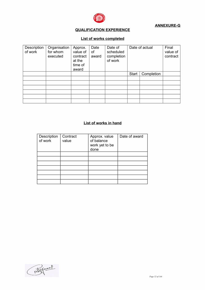
ANNEXURE-GQUALIFICATION EXPERIENCE
List of works completed
Descriptionof work
Organisationfor whom executed
Approx. value of contractat the time of award
Date of award
Date of scheduled completionof work
Date of actual Final value ofcontract
Start Completion
List of works in hand
Descriptionof work
Contract value
Approx. value of balance work yet to be done
Date of award
Page 52 of 144
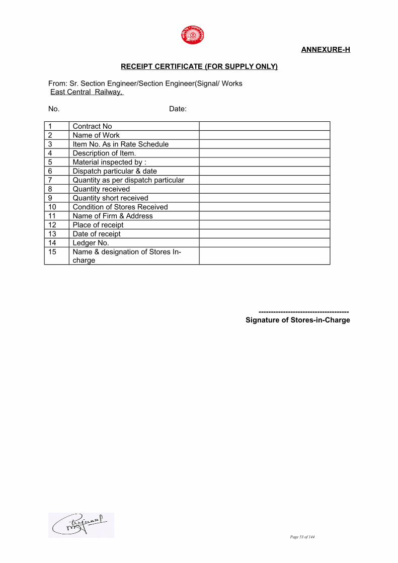
ANNEXURE-H
RECEIPT CERTIFICATE (FOR SUPPLY ONLY)
From: Sr. Section Engineer/Section Engineer(Signal/ Works East Central Railway,
No. Date:
1 Contract No2 Name of Work3 Item No. As in Rate Schedule4 Description of Item.5 Material inspected by :6 Dispatch particular & date7 Quantity as per dispatch particular8 Quantity received9 Quantity short received10 Condition of Stores Received11 Name of Firm & Address12 Place of receipt13 Date of receipt14 Ledger No.15 Name & designation of Stores In-
charge
-------------------------------------Signature of Stores-in-Charge
Page 53 of 144

ANNEXURE-I
EXTENSION OF PERIOD OF COMPLETION OF WORKON CONTRACTOR’S ACCOUNT
(Regd. With A/D)No. Date :To .............................................
.............................................
..............................................
Sub : (i) ................................................. (Name of Work) (ii)Acceptance Letter No. .................................................... (iii) Undertaking /Agreement No. ....................................... Ref : ......................... (Quote specific application of the Contractor for extension to date, if received).Dear Sir,
The stipulated date for completion of the work mentioned above is/was ............... .However, the work is/was not completed on this date. Expecting that you may be able to complete the work if some time is given and inconsideration of your Letter No.............................., the General Manager (or his successor)on behalf of the president of India, although not bound to do so, hereby extends the time forcompletion from ............. to ..............
Please note that liquidated damages @1/2% per week or part thereof of the entirecontract value will be recovered for delay in the completion of the work after the expiry of(1)....................... (give here the stipulated date for completion without any penalty fixedearlier) from you as mentioned in Para 17 (B) of the General Conditions of Contract for theextended period.
The above extension of the completion date will also be subjected to the furthercondition that no increase in rates on any account will be payable to you.
Please note that in the event of declining to accept the extension on the above saidconditions or in the event of your failure after accepting or acting upto this extension tocomplete the work by (2)....................... (here mention the extended date), further action willbe taken in terms of relevant para of Conditions of Contract.
Yours faithfully,
for & on behalf of President of India.Note :-1. Give here the stipulated date for completion without any penalty fixed earlier.2. Here mention the extended date.
Page 54 of 144
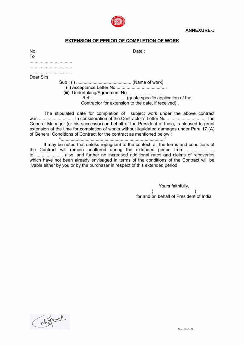
ANNEXURE-J
EXTENSION OF PERIOD OF COMPLETION OF WORK
No. Date :To......................................................................................................Dear Sirs,
Sub : (i) ............................................ (Name of work) (ii) Acceptance Letter No......................................... (iii) Undertaking/Agreement No............................... Ref : .......................... (quote specific application of the Contractor for extension to the date, if received) .
The stipulated date for completion of subject work under the above contractwas ............................ In consideration of the Contractor’s Letter No..............................., TheGeneral Manager (or his successor) on behalf of the President of India, is pleased to grantextension of the time for completion of works without liquidated damages under Para 17 (A)of General Conditions of Contract for the contract as mentioned below :
“...................................................................................” It may be noted that unless repugnant to the context, all the terms and conditions ofthe Contract will remain unaltered during the extended period from ......................to ...................... also, and further no increased additional rates and claims of recoverieswhich have not been already envisaged in terms of the conditions of the Contract will belivable either by you or by the purchaser in respect of this extended period.
Yours faithfully,( )
for and on behalf of President of India
Page 55 of 144
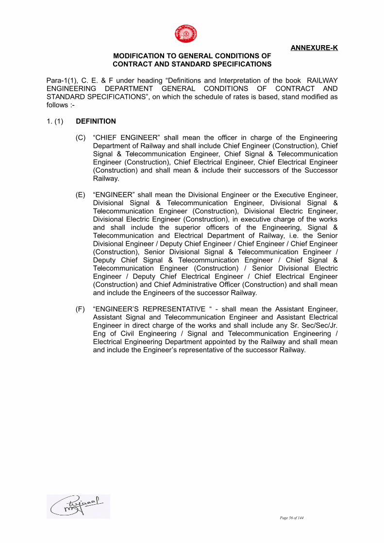
ANNEXURE-KMODIFICATION TO GENERAL CONDITIONS OFCONTRACT AND STANDARD SPECIFICATIONS
Para-1(1), C. E. & F under heading “Definitions and Interpretation of the book RAILWAYENGINEERING DEPARTMENT GENERAL CONDITIONS OF CONTRACT ANDSTANDARD SPECIFICATIONS”, on which the schedule of rates is based, stand modified asfollows :-
1. (1) DEFINITION
(C) “CHIEF ENGINEER” shall mean the officer in charge of the EngineeringDepartment of Railway and shall include Chief Engineer (Construction), ChiefSignal & Telecommunication Engineer, Chief Signal & TelecommunicationEngineer (Construction), Chief Electrical Engineer, Chief Electrical Engineer(Construction) and shall mean & include their successors of the SuccessorRailway.
(E) “ENGINEER” shall mean the Divisional Engineer or the Executive Engineer,Divisional Signal & Telecommunication Engineer, Divisional Signal &Telecommunication Engineer (Construction), Divisional Electric Engineer,Divisional Electric Engineer (Construction), in executive charge of the worksand shall include the superior officers of the Engineering, Signal &Telecommunication and Electrical Department of Railway, i.e. the SeniorDivisional Engineer / Deputy Chief Engineer / Chief Engineer / Chief Engineer(Construction), Senior Divisional Signal & Telecommunication Engineer /Deputy Chief Signal & Telecommunication Engineer / Chief Signal &Telecommunication Engineer (Construction) / Senior Divisional ElectricEngineer / Deputy Chief Electrical Engineer / Chief Electrical Engineer(Construction) and Chief Administrative Officer (Construction) and shall meanand include the Engineers of the successor Railway.
(F) “ENGINEER’S REPRESENTATIVE “ - shall mean the Assistant Engineer,Assistant Signal and Telecommunication Engineer and Assistant ElectricalEngineer in direct charge of the works and shall include any Sr. Sec/Sec/Jr.Eng of Civil Engineering / Signal and Telecommunication Engineering /Electrical Engineering Department appointed by the Railway and shall meanand include the Engineer’s representative of the successor Railway.
Page 56 of 144
ANNEXURE-L
ACKNOWLEDGEMENTFOR RECEIVING MATERIALS AND CABLES FROM RAILWAY
STATION : DATE :
Sub :- Receipt of Materials /Cable from Railway.
It is hereby acknowledged that the following material/ and cable as detailed havebeen received in full and good condition by me on ........................................ at ........................ for the work coming under the AgreementNo.............................. dated ................----------------------------------------------------------------------------------------Sl.No. Description of Material Quantity Remarks and cable (Meter/Nos.) if any----------------------------------------------------------------------------------------
---------------------------------------------------------------------------------------Witnessed by :--------------------------------- ------------------------------------(Signature of Purchaser’s (Signature of Contractor or Representative with Contractor’s Representative) Designation )
Page 57 of 144

ANNEXURE-M
Source for Specifications / Drawings
1. IRS Drawings and Specification - Director General, R.D.S.O., Lucknow
2. TEC Drawings & specifications - Telecommunications Engineering Centre, KurshidLal Bhawan, Janpath, New Delhi - 110 001.
3. Standard Specifications (BSS & ISS, etc.) - Indian Standard Institution, 9, Mathura Road,New Delhi.
4. Railway Publications such as Railway Rules, Codes and Practices, etc. - Government ofIndia, Ministry of Railways, Rail Bhawan, New-Delhi.
5. Signalling Drawings - Chief Signal & Telecom. Engineer, East Central Railway, Hajipur orDy. CSTE/Works/Danapur.
6. Central Government Laws and Acts - Government of India, Ministry of Information,Publications Division, Tilak Road, New-Delhi.
7. Manual of Instructions for Installation of S&T Equipment 25 KV 50 C/S single phaseElectrified section - Director General, R.D.S.O., Lucknow.
Page 58 of 144

ANNEXURE-N
Name of the work :- “Residual works of Replacement of worn out leverframes by panel interlocking at Mokama in Danapur ”
Page 59 of 144
ANNEXURE-O
ROUTE SURVEY FOR OFC / 6 QUAD TELECOM CABLE
1.0 PRELIMINARY CABLE ROUTE SURVEY : The objective of this survey is :
a) Designing and finalizing drawing for the proposed route of the OFC/6 Quadcable.
b) Planning location of track crossing, culverts etc.c) Deciding the cable termination location under the system.d) Deciding system for communication to LC gates, Block working, Emergency
communication etc.e) Planning for extending control communication from cable termination location to
various users in station area and other locations etc.
2.0 POINTS TO BE COVERED UNDER THE PRELIMINARY SURVEY FOR CABLEROUTE.
2.1 Avoiding underground structures, signaling cable, power cables and pipe lines etc. 2.2 Avoid rodent/termite infested or infected side of the alignment.2.3 Off set of the cable trench from the central line of the track such as having burrows.2.4 Avoiding proximity to chemical, paper and such other industries which discharge
chemically active affluent.2.5 Avoiding areas prone to water logging.2.6 Avoiding large rock cutting/thick jungles and areas difficult to approach etc.2.7 Avoid the side of the alignment which is likely to be affected due to addition/alteration
of earth work/super structures (such as doubling, shifting of alignment of the existingtrack etc.) For this, cable route should be discussed with construction and doublingorganization.
2.8 The orientation of the route (left or right side of the track in the sections(c) to be decidedon following:i) That side of main line, which is away from coastal side, other cables such as
signaling and power.ii) Side which is likely to involve least track crossings and likely to be more
convenient for crossing the track, bridges, culverts etc.2.9 Figure out and scale crossing or roads, tracks etc.2.10 Scale out proposed arrangement of crossing bridges, culverts etc,. out of the many
alternative available.2.11Assess special problems, if any, of the section such as undulating surface, long cutting
tunnels etc.2.12 Scale out the cable entry/exit arrangement at the cable termination locations. Avoid
built up areas including those area where building etc. are likely to come up in future.2.13With engineering drawing already in hand, verify pathways/pedestrian crossing and
other lateral clearances.2.14 Scale out the special work required if any and the manner of the cable route in
approach of the existing bridges locations.2.15Identify if any special lengths of cable is required to avoid joints on bridges/culverts etc.2.16For the straight runs as far as possible a separation of 10 M should be kept from the
nearest track. This is as per CCITT recommendation K.8
3.0 PROPOSED CABLE ROUTE PLAN
Page 60 of 144
The proposed cable route plan will show different locations against reference pointswhich are also called chainages. In addition to above all major Engineering land marks like bridges, culverts, etc. canalso be used for all reference points on cable route plan. Hence on completion ofwork, a completion cable route plan will be drawn, which will also show locations of "socket indication posts". Any other reference point for the purpose bench marking, the cable route asdiscussed with Engineer in charge of work will also be shown on cable route plan.Based on above survey, the cable route plan should be prepared.
3.0 OFC/6 Quad telecom cable route plan (5 Km. charts) with horizontal scale as 1 Km.=10Cms. approx. The ASM's office, etc. are to be marked on the chart.
3.1 Drawings of the laying of the cable in special terrain viz. Station yards, Approaches ofcable huts, Long bridges, Culverts etc. are also to be made to show the details.
3.3 The name of location should be put in the LOC column and the chainages in thechainage column. The Km. post No. should be written. The name of station should beshown against the locations of the SM’s office.
3.4 Based on the survey, the No. and the length of culverts, bridges and LC gates shouldbe marked on the track line of the cable route plan. The survey party will prepareprints of 5 Km. chart with the above details entered for to mark the route and otherdetails after surveying.
3.5 The actual measurement of the separation distance from the centre line of the track (Theadjacent main line) is to be shown on the 5 Km. chart.
3.6 Based on the requirement of various types of circuits proposed quad allocation of 6Quad cable is prepared.
3.7 The requirement of tapings of different control circuits are assessed based on theexisting communications arrangements in consultation with the Open line Railwayusers and a tentative chart shall be prepared.
3.8 All the plans and drawings shall be neatly prepared by using CAD and Plotter etc. Thedrawings shall be in A3 or A4 size and suitably filed for ease of handling.
4.0 INFORMATION IN CABLE ROUTE PLAN The cable route plan shall contain following:-
4.1 Whether the cable route is on UP or DN side of the Railway track.4.2 Approximate location and lengths where the cable shall be laid in G.I. and RCC pipes
under the bed on culverts.4.3 Locations of track crossing and the number of tracks to be shown.4.4 Locations of road crossings to be shown.4.5 Locations and length for protection of cable in rocky area and platform cutting etc to
be shown.4.6 Proximate locations of derivation joints, LC gates or emergency sockets posts to be
provided on OFC/6 Quad cable should be shown.
5.0 DETAILS CABLE ROUTE SURVEY
5.1 The purpose of detailed survey is to undertake the closer study of the variousexisting telecommunication facilities, to work out the exact requirement of the 6 Quadand derivation/PIJF cables and materials required for different items of work, finalizeall the drawings and site plans required for the execution of the work as also to
Page 61 of 144
examine the details collected during preliminary survey and to affect necessarychanges/modifications, if any.
6.0 MAIN ITEMS OF WORKThe following are the main items of work which should constitute the detailedsurvey:-
6.1 Closely examine the proposed cable route and prepare cable route plans.6.2 Preparation of route charts for derivation / PIJF / 6Quad cables with the size and
length of the cables for each tapping and termination arrangement.6.3 Estimating of requirement of special cable lengths of cables for long girder bridges.6.4 Deciding location of each joint and preparation of a joint schedule. 6.5 Working out the exact length of derivation / PIJF / 6Q cable required.6.6 Preparation of material schedule required for different protective works.6.7 Arranging isolated telephone circuits to be provided in the cable.6.8 Investigation on special problems of the section and finding out proposed solution
thereof.6.9 Examination of chemical composition of soil to see whether any special precaution are to
be taken to protect cable from soil corrosion.
7.0 FINALISATION OF CABLE ROUTE PLAN.
The following are the guidelines for finalizing the route and preparation of the cableroute plan:-
7.1 Prepare the "5 Km. charts" as explained above showing the relevant chainages anddetails in the charts.
7.2 Actual measurement by 30M steel tape or chain along the route is necessary only incase of important locations to be terms as "special terrains" for example, approach torepeater station/Cable hut, long bridges, big yards, sharp diversions in the cableroute from its parallel course along the main railways track due to obstruction, cuttingetc.
7.3 Inspect and decide the portions of route falling in category of "special terrains" i.e. whereactual longitudinal measurement is necessary.
7.4 The remaining portions of the route i.e. other than the portion decided as "specialterrain" are to be terms as "straight runs". Actual chaining along the route is notnecessary for such 'straight runs' and these can be marked on the '5 Km. charts'.
7.5 The cable route should be started from a repeater cable hut station. Actualmeasurement along the route should be done by means of a 30M steel tape for a fewdrum lengths up to a convenient point along the main line where from the distancealong the route may be reckoned from the Plan. A termination allowance of 5M cablelength inside the repeater station/cable hut building should be made, in addition to alength of about 10M being kept in a pit just outside the building.
7.6 It should be ensured that both "special terrains" and "straight runs" should consist of fulldrum lengths, so that the position of joints (other than 'T' joints) is fixed withoutdifficulty in both the cases.
7.7 In case of special terrains, the separation distance at some points on the route mayalso have to be reckoned from some other permanent structures depending upon thesite conditions.
7.8 The separation distance of the cable route from the nearest track on the "straight runs"should be 10M approx. The deviating from this standard separation of 10M should bekept to the minimum and as soon as any obstruction has been negotiated, the routeshould again follow this standard separation distance. It is desirable from the point of
Page 62 of 144
view of calculating the induced voltage that the uniformity of the separation ismaintained for the maximum possible length of the main cable route.
7.9 Separation distance should be marked on the "straight runs" portion of the cableroute plan (5 Km. chart) at appropriate intervals. In addition, the separation distanceat points of change in the cable route such as diversions, track crossings,approaches to bridges, culverts, etc. should invariably be marked on the cable routeplan in such a way as the intended cable route is clearly defined for "special terrain"the separation distance should be marked at as close intervals as is considerednecessary depending on the site conditions.
7.10The route should be decided by walking along the track. 7.11 Actual measurement should be made for the protective works required for the cable
passing over the culverts, under tracks, over long girder bridges, level crossings,rocky areas, under the bed of culverts.
8.0 FINALISATION OF TAPPING DIAGRAM
8.1 The survey team should visit each location such as cabin, SM's offices, Loco sheds,cabins, gate lodges, etc. and verify the details collected during the preliminary surveyof all the existing telecommunication facilities, and additional telecommunicationfacilities to be provided.
8.2 The position of each tapping should thus be finalized and a final tapping diagramprepared.
9.0 ISOLATED TELEPHONE CIRCUITSIt is necessary that all the telephone circuits such as isolated quarry sites, gatelodges, etc. are taken note of and provision made for transferring the overheadalignment into cables wherever considered necessary.
10.0 LENGTH OF OFC/6 Quad CABLEThe cable length is worked out on following basis to arrive at the locations of the
straight joints:-a) Extra length for track crossing including 2.5M loop on each side etc.b) Extra length on approach/crossing of the bridges and culverts as per
measurement in the detailed survey.c) 10M of cable to be kept on either side of major steel bridges and 5M on minor
bridges.d) At every joint a loop of 5M on either side.e) In cable hut a loop of 10M in the cable pit.
11.0 SIZE & LENGTHS OF DERIVATIONS/PIJF CABLES AND ROUTE CHARTS
The derivation/PIJF/6Q cables are required to be laid from ASM's office to cabins,enquiry office & other operational points. Depots, supervisor's residence etc. forextending controls tapings. The plan and requirement of different sizes ofPIJF/derivation/6Q cables shall be suitably worked out. As for as possiblederivation/PIJF/6Q cables shall be laid in the trenches for main telecom cables andbranched off at suitable locations.
Page 63 of 144
ANNEXURE-P
LAYING AND JOINTING OF OFC / 6 QUAD TELECOM CABLE
1.0 PREPARATION OF JOINT SCHEDULES
1.1 The details of type and number of joints in main OFC/6 Quad cables is required to beworked out based upon the location of emergency sockets, obligatory locations, LCgates etc. The typical drum lengths of 6 Quad telephone cable is 1 Km. approx andtherefore, it shall generally be possible to combine straight through and emergencyjoints. VF transformers 1 quad/2T, 470:1120 shall be used. Phantom will be derivedat all emergency sockets and repeaters.
1.2 No isolation transformer is considered necessary for LC gate & other locationtelephones up to a distance 7.5 Km. on 6 Quad telephone cables.
1.3 The jointing schedule shall be made as straight-line diagram indicating the locationsof various joints with reference to chainages. The length of 6 Quad cable fromleading cable hut/ASM's office shall be specifically indicatied.
1.4 The requirement of termination boxes for cables at various locations shall be workedout.
2.0 CABLE LAYING:
2.1 It is advisable to employ the same people at the same place or job while cable isbeing laid.
2.2 Before commencement of the laying inspection of the trench and inspection ofprotection works should be carried out so as to ensure their conformity with thespecification. The trench bottom should be clean, smooth and free of small stone.
2.3 The cable drum should be brought as close to the cable trench as possible. it should be
lifted with the aid of cable jacks firmly mounted on a support of stone or wood .
2.4 Where necessary the cable drum may be placed at such a point so that 2/3 of thecable is laid directly and the balance in other direction. Care should be taken in sucha case to see that there are no kinks or loops in the cable.
2.5 The wooden battens on the drums should be carefully removed shortly prior to layingand before the drum is mounted on the jack. The nails on the lagging should becarefully removed.
2.6 While rolling a cable drum for laying the drum shall be supported on an axle runningthrough its centre. The height of the axle running through its center being such thatthe end frames are free to rotate and do not touch the ground at any point. The cableshall be carefully uncoiled by gently pulling the cable assisted as necessary bycarefully turning the drums quick pulling of the cable or turning the drums shall beavoided at all costs. Each cable drum shall be broken while laying is in progress toprevent sharp bending or buckling, particularly when the cable coils are stickingtogether.
Page 64 of 144
2.7 The following personnel shall be employed near the drum.1 Man : for handling the brakes.1 Man : for permanent observation of the uncoiling of cable.2 Men : for uncoiling close to the drums.
2.8 When drums are turned for change of direction , wooden blocks shall be carefully putunder the drum bolts which stand out from the drum discs.
2.9 It is customary for the mate to stand in a commanding position where he can view theentire route and shout evenly timed calls to his men to pull. If there is propersynchronization between the mate's calls and the pulling by the men, the cable willleave the drum without difficulty. It is important that the cable should be pulled withsteady and even pulls and not be unnecessarily jerked or strained. On no accountshould a cable be allowed to twist or kink as this is likely to spring the Armour andfracture the insulation and outer serving of the cable. When pulling cable aroundbends, one or two men should be stationed to give the cable the correct bend when itpasses.
2.10 When the cable drums are exposed to great heat before laying, then danger existsthat the individual coils and layers stick together in spit of the half overlay.
2.11 Special attention should be paid to see that no buckling of the cable occurs whilepulling the cable. A man should stand near the drum and loosen the cable carefullyby hand and shout a warning whenever the cable can not be loosened. Separationmust be affected as close to the drum as possible as otherwise kinks may result. Therate of pulling should also be slow to prevent possible damage to cable that is beingcarried when the paying out stops. The drum should be kept in shade wherepossible.
2.12While laying the cable employ adequate number of men such that the cable can beconveniently carried by them in both hands without stretched arms. The distancebetween any two persons carrying the cable shall be from 2 to 10 metres dependingupon weight of cable such that the maximum sag of the cable between any twopersons is not more than 0.5 meters.
2.13 The cable shall be gently drawn by pulling the cable which may be assisted asrequired by smoothly and slowly turning the winch. The cable shall not be twisted onany account
2.14 Before laying is commenced the cable shall be uncoiled first in a straight linesupported by men and then carried to the trench and laid gently & carefully.
2.15While the laying work is in progress one man must continuously observe the cable andfeel along its length in order to determine whether any indentations holes or otherdamaged parts are apparent. Such damaged parts have to be protected immediatelyby the cable jointer provided with the laying party.
2.16 When two or three turns of cable are left on the drum the pulling should be stoppedand the inner end of the cable removed from the slot in the drum. pulling should thenbe continued. if this is not done the cable end is likely to be stretched and damaged.
2.17 The ends of the telecommunication cable should have an overlap of appropriatelength at the end of each drum for jointing purpose.
Page 65 of 144
2.18The conditions of the cable shall be visually inspected through out its length and in caseany damage or defect is noticed, the trench shall not be filled up until the engineer'srepresentative in notified to examine and authorize filling of the trench.
3.0 MINIMUM BENDING RADIUS:
Cable should always be bent (or straightened) slowly; They should never be bent tosmall radius while handling. The minimum safe vending radius for telecommunicationcables should be 30 times the diameter of the cable but wherever possible largerradius should be used.
4.0 CABLE RESERVE:
a) At the following locations, it will necessary to provide reserve cable for futurepossible use.
1) Where a change to cable line is expected, the reserve to be allowed dependingon the circumstances.
2) Near roadways, buildings and culverts reserve of 5 M should be allowed at drumend.
3) One each side of major girder bridges a reserve of 10M should be left. For minorbridges 5M shall be left.
4) Where remodeling works on culverts, bridges and track doubling work are goingon, it may be necessary to keep loops of cable as an extra reserve pendingfinalization of its future route.
5) At the cable hut a loop of 10M in the cable pit.6) At every joint a loop of 5M on either side.
5.0 LAYING OF DERIVATION CABLE
The derivation cable are required to be laid from cable hut to the subscriber premises(ASM, Cabin Depots, Residence, LC gates, etc.) and from main cable trench toemergency post for extending control and other tapings . The plan & requirement ofPIJF/derivation/6Q cables shall be suitably worked out and got approved from theEngineer well in advance.
As far as possible derivation/PIJF/6Q cables shall be laid in the trenches/protectiveworks already done for 6 Quad cables. From the diversion point, cables shall have tobe laid on independent trenches. For trenching out different tapings en-route, thecable may be tapped at different locations. However, it must be ensured that everytapping is taken on independent conductors right from cable hut to the subscriber forease of isolation in case of malfunctioning.All the required protective works shall be implemented for protecting these cables.
6.0 TOOLS REQUIRED FOR TRENCHING CABLE LAYING AND FILLING
In addition to the tools mentioned below all tools & plants required to speed up thecable laying through mechanized methods will be utilized by the contractor.
Sl.No. Tools Name 1. Cable jack2. cable grip3. Reopening device4. Free hood hook5. Shackle free head hook
Page 66 of 144
6. Grouling hook.7. Pulling bolt8. Tension meter9. Pulley10. Anti twist device (swivel)11. Roller12. Flexible cable13. Pulling Rope14. Brush15. Mandrel16. Chain17. Measuring cord for strain gauge18. Slip winch19. Wire rope20. Portable VHF set21. Measuring tape22. Fawrah23. Iron plate.24. Loader backhoe for drilling25. Warning tape26 Caterpiller Tractor27, Fork lifter28. Vehicle Van type29. Tacho meter30. Road measurer.
7.0 PULLING OF OFC CABLE AND INSTALLATION OF OFC CABLE PIT:
7.1 The OFC cable shall be gently drawn through permanently lubricated HDPE pipe bypulling the cable which may be assisted as required by smoothly and slowly lumingthe winch. The cable shall not be twisted on any account. The 6Quad cable shall belaid out side the HDPE pipe taking adequate care so as not to wind the cable aroundthe HDPE pipe if both the cables OFC & 6Q are to be laid in the same trench.
7.2 Before laying is commenced, the HDPE pipes shall be laid in the trench and jointedby sockets.
7.3 While the laying work is in progress one man countinously observe the cable and fillalong its length in order to determine whether any indentations holes are otherdamaged parts are apparent. Suchdamaged parts have to be protected immediatelyby the cable jointer provided with the laying party.
7.4 The conditions of the cables shall be visually inspected through out its length and incase any damage or defects is noticed, the trench shall not be filled upo until theEngineer Incharge is notified to examine and authorizes filling of the trench.
7.5 The proposed OFC cable is an armoured type and delivered in reels of up to 3 Km.approx. As the armoured OFC cable can not be blown for 1 Km, the cable to bepulled through 40/33 mm HDPE duct at every 300 meter with the use of “Pythonrodder” two nylon ropes shall be used as a lead wire. These nylon ropes to besupplied by contractor.
7.6 Two such lengths of ropes shall be laid through the pipes so that after the cable isthreaded through the pipe one lead rope is permanentaly left in the pipe with asuitable overlay at two ends to unable the cable to be pulled out at a later stage ifrequired to do so.
7.7 At every joint OFC/RCC cable pit to be placed at a depth of 1 meter by properdigging. The HDPE pipe will enter the OFC / RCC pit from the bottom of the trench ateach side.
Page 67 of 144
7.8 5 meter HDPE pipe drawn from both side of the trench shall be rounded of in side thepit. While laying the armoured OFC cable, the HDPE pipe shall be sealed by sealingcap. 5 meter OFC cables out side the HDPE pipe shall be kept spare in the pit.
7.9 After laying of the cable the OFC/RCC pit shall be filled with sand and covered withthe 2 part covering slave 75 mm thick with lifting anchor and finally to be covered byloose soil up to earth surface with proper ramming. All material to be supplied by thecontractor.
7.10 Before pulling the OFC cable, OTDR test has to be conducted for all 24 fibers of theOFC in 1310nm to 1550nm windows readings to be recorded in soft as well as hardcopy. The durms with any defects for even one single fiber shall not be blown /pulled. Such defects shall be immediately brought to the notice of the Engineer –In-charge and a joint statement has to be signed for record. The durm test results shallbe recorded and signed jointly. Pulling to be done only after this test procedure.
7.11 Replacement of defective OFC: No defects like high loss events and fiber breaks arepermitted and the contractor shall at his own cost replace the enter drum length ofthe cable of Railway’s specification and in any case not less than the length of thedurm being re-laid. The contractor also at his own cost will blow/pull the cable againincluding the splicing / termination of the cable. No joints with pieces of OFC arepermitted. In case of any deviation specific approval from Engineer-In-charge shouldbe obtained
8.0 TECHNIQUES FOR JOINTING OF FIBRE OPTIC CABLE:
8.1 Following types of techniques are used for splicing of fibres: -a) Mechanical Splices.
This aligns the axis of the two fibres to be joined and physically hold themtogether.
b) Fusion SplicingThis is accomplished by applying localized heating (i.e. by electric arc or flame) atthe interface between two butted, prealigned fibre ends, causing them to softenand fuse together.
8.2 Mechanical splicing can be used for temporary splicing of fibres or where fusion splicing is impractical or undesirable.
8.3 At all other location and during initial installation of fibre optic cable, fusion splicing should be adopted.
9.0 STRAIGHT JOINT FOR FIBRE OPTIC CABLE
9.1 There are various type of joint enclosures available in the market. The procedure for assembly of joint closure is described in the installation manual supplied with straight joint closure. This includes the following:
a) Material inside joint closure kit.b) Installation tools required.c) Detailed procedure for cable jointing.d) Procedure for re-opening the closure.
9.2 The Optic Fibre straight through joint closure shall be as per specn. RDSO/SPN/ TL/25/98 with latest modification. The joint shall be protected in brick chamber as pergiven drawing (cable pit for OFC joint)
9.3 However, generally, the following steps are involved for jointing of the cable.
Page 68 of 144
- Preparation of cable for jointing.- Stripping/cutting the cable- Preparation of Cable and joint closure for splicing.- Stripping and Cleaving of Fibres.- Fibre Splicing.- Organising fibres and finishing joints.- Sealing of joint closure and- Placing joint in pit.
10.0 PREPARATION OF CABLE FOR JOINTING
a) During the installation, a minimum of 10 meter of cable of each end is coiled inthe joining pit to provide for jointing to be carried out at convenient location aswell as spare length to be available for future use in case of failures.
b) The pit size must be chosen carefully to ensure the length of the wall on whichjoint is mounted is greater than closure length plus twice the minimum bendingradius of the cbale. A pit length of 1 meter is sufficient for most of the cable andjoint closures. Bracket to support the cable coil are also fixed on the wall of thepit.
c) The cable is then coiled on to the pit wall in the same position as required afterthe joint is complete. The marking is done on all the loop so that it will be easierinstalled it later.
d) Sufficient cable at each end up to the jointing vehicle/enclosure is then uncoiledfrom the pit for jointing.
11.0 STRIPPING/CUTTING OF THE CABLE
a) The cable are stripped of their outer and inner sheath with each sheath staggeredapproximately 10 mm from the one above it.
b) Proper care must be taken when removing the inner sheath to ensure the fibresare not scratched or cut with the stripping knife or tool. To prevent this, it is best toonly score the inner sheath twice on opposite side of the cable, rather than cutcompletely through it. The two scores marking on either side of the cable are thenstripped of the inner sheath by hand quite easily.
c) The fibres are then removed from cable one by one and each fibre is cleanedindividually using kerosene remove the jelly.
12.0 PREPARATION OF CABLE JOINT CLOSURE FOR SPLICING
The type of preparation work performed on the cable prior to splicing differs on the type of joint closure and fibre organiser used. However, the following steps are usually common: -
a) The strength member of each cable is jointed to each other and/or the centralframe of the joint closure.
b) The joint closure is assembled around the cable.
Page 69 of 144
c) The sealing compound or heat shrink sleeve is applied to the cables and closure,or prepared for application after splicing is complete.
d) The fibres are protected (usually with plastic tubing) in their run from the cablecore to fibre organizer trays (particularly if cable construction is slotted core type).
e) Tags which identify the fibres no. are attached at suitable location on the fibres.
f) Splice protectors are slipped over each fibre in readiness for placing over thebare fibre after splicing.
13.0 STIPPING AND CLEAVING OF FIBRE
a) Prior to splicing each fibre must have approximately 50 mm of its primaryprotective U.V. cured coating removed, using fibre stipper which aremanufactured to fine tolerances and only score the coating without contacting theglass fibre.
b) The bare fibre is then wiped with a lint free tissue doused with ethyl alcohol.
c) Cleaving of fibre is then performed to obtain as close as possible to a perfect 90degrees face on the fibre.
14.0 SPLICING OF THE FIBRE
As discussed above there are two types of methods which can be used for fibre splicing. Some of basic steps for both the type are as under: -
15.0 FUSION SPLICING OF FIBRE
Some of the general steps with full automatic micro processor control splicing machine are as under: -
a) Wash hands thoroughly prior to commencing this procedure.
b) Dip the clean bare fibre in the beaker of ethyl alcohol of the ultrasonic cleaver.Switch on ultrasonic cleaver for 5-10 seconds (Some of the manufacturers doesnot prescribe the above cleaning).
c) Place the bare fibre inside ‘V’ grove of splicing machine by opening clamp handlesuch that the end of fibre is app. 1 mm over the end of ‘V’ groove towards theelectrodes.
d) Repeat the same procedure for other fibre, however, first insert heat shrink spliceprotector.
e) Press the start button on the splice controller.f) The machine will prefuse, set align both in ‘X’ and ‘Y’ direction finally fuse the
fibre.g) Inspect the splice on monitor if provided on fusion splicing machine and assure
no nicking, bulging is there and cores appears to be adequately aligned. If thesplice does not visually look good repeat the above procedure.
h) Slide the heat shrink protector over the splice and place in tube heater. Heat iscompeting when soft inner layer is seen to be ‘oozing’ out of the ends of outerlayer of protector.
i) Repeat for other fibres.
Page 70 of 144
16.0 MECHANICAL SPLICING OF FIBRE
In this there are two types of splicing system, one with precision alignment of fibre in ‘V’ groove and their ends are sealed with some index matching fluid and adhesive. The other uses ultrasonic light source for curing optical adhesive in addition to alignment etc.
The general steps involved for above are as under: -a) Stripping and cleaving of fibres is done as per clause 4 and 6 above.b) Remove protective end cap from mechanical splice and pull out vent tube.c) Inject adhesive as specified by supplier in to splice.d) Insert fibre until it butts against fibre end already bonded in place.e) Cure adhesive with UV light following exposures times as indicated by supplier, if
required.f) Repeat the same procedure for all the fibres.
17.0 ORGANISING FIBRE AND FINISHING JOINTS
a) After each fibre is spliced, the heat shrink protection sleeve must be slipped over the bare fibre before any handling of fibre take place, as uncoated fibres are very brittle and can not withstand small radius bends without breaking.
b) The fibre is then organized in to its tray by coiling the fibres on each side ofprotection sleeve using the fully tray side to ensure the maximum radius possiblefor fibre coils.
c) The tray are placed in the position.d) OTDR reading taken for all splices in this organized state and recorded on the
test sheet to confirm that all fibres attenuation are within specification. This OTDRtest confirms fibres were not subjected to excessive stress during the organisingprocess.
e) After this the joint can be closed with necessary sealing etc. and ready forplacement in the pit.
18.0 PLACING OF COMPLETED JOINT IN PIT
a) Joint is taken out from the vehicle and placed on the tarpaulin provided near thepit.
b) The cable is laid on the ground, loop the cable such that pen mark previouslyplace on the cable line up. Tape these loops together at the top of the coil.
c) The joint can now be permanently closed and sealed by heating heat shrinkablesleeve etc. However, before closing, silica get to be kept inside for moistureprotection.
d) Now the joint closure is fixed to the bracket on the pit wall and pit is closed.
19.0 RE-OPENING OF THE PIT
If required for attending to faults etc, manufacturers supply special kits for opeining ofjoint and the steps to be followed. However, the general steps are as under: -a) Using suitable knife cut heat opening shrink sleeve longitudinally along its entire
length.b) Do not damage the smaller heat shrink sleeve on the ends of joint.c) Apply heat to the cut sleeve until it begins to separate.d) Gently remove the cut sleeve from the joint. Now the joint can be opened.e) Protective sleeve/cover can be removed for attending to faults etc.
Page 71 of 144

20.0 TERMINATION JOINT FOR FIBRE OPTIC CABLE
20.1 This joint is provided in the cable hut for terminating the outdoor fibre optic cable ofboth the sides, splicing through Fibres, connecting fibres to pig tails for connection tooptical line terminal equipment etc.
20.2 The OFC cables shall be dressed up on teak wood plank/Aluminum ladder insidecable hut. (The armour of the OFC cable shall be cut before taking the cable in theequipment rack). The cables shall be terminated on OFC termination joint box.
The Optic Fibre termination joint box as per specification No. DOT G/FTB-01/02March 99 with latest amendments shall be provided in each cable hut to terminateboth optical fibre cables and deriving required pig tails. Two pairs of fibres shall bederived from either side cable for 2 Mb streams at every OFC cable hut throughpigtails with a FC/PC connectors. All the fibres from both sides at Repeaters shall beprovided with FC/PC connectors to connect FDF.
20.3 Jumper Cable (10 Metre long)
The jumper cable shall be cut into two pigtails of 5 Metre long which is consideredadequate. Once fibre termination box mounted on equipment rack itself. The materialmay be supplied as per latest specifications.
20.4 The procedure for installation of termination joint box depend upon the type of jointenclosure. The installation manual supplied give the step by step procedure forinstallation. However, the general steps are as under: -
- Marking the cable.- Stripping/cutting the cable.- Treatment of tension member- Fibre splicing.- Enclosing fibre.- Fixing strength member.- Closing the cover.- Fixing the termination box.- Fixing the cable.
21.0 FIBRE DISTRIBUTION FRAME:
21.1 The fibre distribution frame complete shall be as per ITU/TEC standards with FC/PC connectors and fittings.
21.2FDF shall be suitable for termination of 48 fibres.21.3It shall be suitable for mounting on standard 19” equipment rack.21.4It shall be as per DOT specification no. G/FDF-01/01Jan’93 with latest amendment
22.0 MARKING THE CABLE
a) Determine the cable length upto the proposed location of termination box. It isalso to be ensured that atleast 10 meters of cable is coiled in the cable pit.
b) Determine the cutting point and mark the cable.c) Determine the sheath peeling point and mark the cable.
Page 72 of 144
23.0 CUTTING/STRIPPING THE CABLE
a) Cut the cable as per marking.b) Remove the sheath from cable ends. During sheath stripping care should be
taken not to damage the fibres.c) The length and the steps for various sheath by cutting shall be as per the
instruction given in the manual.
24.0 GRIPPING THE CABLE
a) Wind PVC tape around the cable core just beside edge of the sheath.b) Insert the bushing inside sheath by cutting the cable sheath for about 25 mm.c) Place the sheath grip (lower half and upper half) and cut tighten it with the help of
torque wrench.
25.0 FIXING OF TENSION MEMBER
a) Mark the tension member for specified length and cut it.b) Clean the tension member thoroughly by Alcohol and cotton cloth.c) Fix tension member holder with the help of instant adhesive at the end of tension
member.
26.0 FIBRE SPLICING
The procedure for splicing is same as described in Para 14, 15 & 16 above.
27.0 ENCLOSING FIBRES
a) Set the fibre cassette on the base.b) Arrange excess length of fibre to make double figure of eight.c) Enclose the spliced fibre and its excess length carefully.d) Repeat the procedure for other fibres.e) After this, the box can be closed. However, a packet of silica gel may be placed
inside for protection from entry of moisture.
28.0 MOUNTING OF TERMINATION BOX
Termination box can be fixed either on wall or on equipment rack.a) Mark the fixing holes on the wall/bracket/frame.b) Place the termination box and tightened the nuts inside the base box.c) Put the covers.
29.0 FIXING THE CABLE
Secure the cable on wall/frame at two places within one meter from termination box keeping in view straight entry of cable in termination box.
30.0 ISOLATION OF ARMOUR OF OFC CABLE
The maximum continuous length of armour of OFC cable should not exceed 1.6Kms. In order to keep the induces voltage within permissible limits. Where thecontinuous length of cable exceeds 1.6 Kms, 1 50 mm cut shall be covered bysuitable heat shrink sleeve as per TEC specifications.
31.0 ACCEPTANCE TEST FOR FIBRE OPTIC CABLE
The various optical and mechanical test which are to be conducted on optical fibersand on finished cable during the protoytpe tests and acceptance test are detailed inthe specification No. TC-55 for armoured fiber optic cable.
Page 73 of 144
The procedure for testing of Fiber optic cable shall be jointly finalised by contractorwith Engineer of the Railways. The parameters specified by manufacturer shall betaken as reference. The test shall be conducted from cable hut to cable hut once, thesplicing and termination joints are completed. The length of cable (as per marking incable & OTDR) loss in cable, average loss per Km, No. of splices, splice loss, etc.shall be recorded and jointly signed as per proforma given in para 24 below.
32.0 TEST PROTOCOL FOR OPTICAL FIBRE CABLE
SYSTEM TEST PROTOCOL OPTICAL FIBRE CABLE FIELD TEST
Route: _______________________ Date: ____________________Station: ______________________ No. of mid-
Section splices: _______________________
Section: ________________________ Measured by: _______________________Length Length as per meter(By OTDR): ____________________ Marking on cable sheath: ________________
1) Optical Measurements (on Line):
Measurement Fibre-number Accepted Value1 2 3 4 5 6 7 8
1.1 Total attenuationat 1300 mm with OTDR
1.2 Total attenuation perKm. 0.15 db/Km.
1.3 Splice loss in db Averagewith OTDR location splice loss
Average splice loss 0.15 db
NOTE- ALSO ATTACH OTDR RESULTS
2. VISUAL INSPECTION (ON LINE):
2.1 S. No. of cable and length of each drum:
S. No. LENGTH
1. _______________________ ___________________________ M
2. _______________________ ___________________________ M
3. _______________________ ___________________________ M
4. _______________________ ___________________________ M
Page 74 of 144

5. _______________________ ___________________________ M
2.5 Location of Isolation sleeve: 1. 2. 3.
Contractor’s Representative Railway Representative
33.0 TOOLS AND EQUIPMENTS REQUIRED FOR JOINTING AND TERMINATION OF FIBRE OPTIC CABLE
S. NO. TOOL’S Name
1. Branch joint closure.2. Termination Box.3. Rubber end Block.4. Sheath Clamp.l5. Bushing.6. Strength member holder.7. Heat Shrinkage tube.8. Arc fusion splicer machine.9. Power cord AC/DC.10. Walkie-Talkie 12 V DC source.11. Tube heater.12. Precision cleaver.13. Cable sheath stripper14. Fibre stripper.15. Knife for HDPE cutting.16. Hecksaw for strength membrane.17. Isopropyl alcohol or methanol of high specific gravity.18. Johnson Buds.19. Tweezers.20. Gun heater Blower type.21. Sleeve for splice protection.22. O. T. D. R.23. Stickers for numbering of splices.24. Portable k. oil generator.25. Umbrella 2 Nos.26. Dust protection for splicing machine.
34.0 JOINTING OF 6 QUAD TELECOM CABLE WITH ACCEPTANCE TEST:
The contractor will follow instructions issued by approved supplier of Theremoshrinkjointing kit, provided such instructions are issued formally by the supplier and it iscertified that joint will be free of defect.
34.1Jointing & termination of PIJF quad & derivation cables.
34.2Thermo shrink joints of appropriate size for straight through or branch off joints as perDOT specification shall be provided.
Page 75 of 144
34.3 All the derivation/PIJF cables shall be terminated on Krone or CT box of suitable sizedually mounted on cable huts / ASM room and other locations as advised by the siteengineer.
35.0 CAPACITANCE UNBALANCE
35.1 In the electrified sections, the capacitances unbalances between cable conductorsand cable sheath/Armour (earth) introduces appreciable noise in the circuits. Thiscan be reduced by polling i.e. connecting cable pairs straight or across at normaljoints.
35.2 In any manufactured length of a cable, the capacitance between conductors of aquad and between conductors of adjacent quads and those between conductors or apair and the cable sheath (earth) are not perfectly balanced which gives rise to thecapacitive interference between various circuits and the circuits and earth. Balance ofthese capacitances is hence necessary to limit the cross talk and bring the cross talkattenuation within permissible values.
This is done by adding extra capacitances between pairs. The permissible limits ofcapacitance unbalances in balanced cabling is 40 pf for full loading section.
36.0 ACCEPTANCE TEST FOR 6 QUAD AND PIJF CABLES
The characteristic impedance of unloaded 6 Quad cables (IRS/TC/30) is 470 (+-10%) at 800 Hz. when loaded with inductance of 88 mH, the characteristicimpedance is 1120 (+-10%).
Joint tests are to be carried out by engineer's representative and contractor'srepresentative for accepting the cables from the contractor.
37.0 TESTING OF VF TRANSFORMER:
Following tests may be conducted on VF transformers before using in the joint:-
a) Continuity and DC resistance of windings:- Use and AVO meter to checkcontinuity, measure DC resistance of primary/secondary windings with LCRbridge. The readings obtained should be comparable.
b) Insulation resistance:- Connect one lead of a 500 V megger to one windingconnect the other lead of Megger first to another winding and take reading . Nextconnect it to all other windings connected together and the case and again takethe reading insulation resistance should not be less than 10,000 Mega Ohms.
c) Insertion Loss:- Adjust output level of transmission measuring set to O/dB andconnect it across the primary of transformer connect a dB meter on thesecondary side. dB meter reading should not be more than 1 dB.
38.0 LOOP RESISTANCE AND CONTINUITY TESTInstruments to be used : Multimeter
a) The multimeter will provide ready means for continuity test and also it will becapable of testing D.C.and A.C.Voltage D.C. resistance and also low frequencylevels for test and maintenance purpose. The input sensitivity shall be at least100K Ohms per volt D.C.and 10K Ohm per Volt of A.C.
Page 76 of 144
b) The maximum average loop resistance of a pair measured with direct current at20 Deg C shall be 58 Ohm per Km. for the PE quad of 0.9 mm diameter Cuconductors. The normal loop resistance of a pair shall be 55.2 Ohm per Km. at 20Deg C. This test shall be carried out only on untapped pairs of cable.
39.0 INSULATION TEST.
Instruments to be used- Me ohm Meter/Megger. The insulation resistance measuredbetween a conductor of a quad and all conductors of all other quads connectedtogether to the sheath and earth shall not be less than 625 mega ohms per Km.When measured at 100 volts DC after energising for one minute at a temperature ofnot less than 16 deg. C. The remaining three conductors of the quads under test maybe left floating.The insulation at 16 deg. C may be found out by the formula.Insulation at 1/2 insulation x 1.04(T-16(16)x9/5. 16 deg. C.For measuring insulation all conductors may be bunched together and tied properlywith a bare wire and insulation to the sheath/ screen measured. The insulationresistance per Km. can be obtained as - No. of wires tested x deflection ( Megs (c) xLength (KM Me ohms per Km.)
40.0 FREQUENCY ATTENUATION & TRANSMISSION MEASUREMENT.
Instrument to be used - Transmission Measuring sets ( IRS TC 43/87). Twotransmission measurement sets are required for this measurements. One set is keptat one end of the cable and the other at the other end of the cable. Before sendingthe set to other end the zero errors of all meters are checked. Zero dB tone is dent from one end and the level received at the other end and ismeasured. Whenever the frequency is changed the zero level should be adjustedagain Zero level of the tone should also be adjusted first before taking any reading.The reading are taken at the following frequencies 300Hz, 400Hz, 600 Hz,800Hz.1000 Hz, 1400 Hz, 1600 Hz, 2000 Hz, 2400 Hz, and 3000 Hz and recorded.
41.0 CROSS TALK MEASREMENT.
Instrument to be used a (c) cross talk measuring set ( IRS EC - 45) b (c) oscillator 1Khz / 800 Hz. Zero dB, Tone of 800Hz is given on one pair and cross talks ismeasured on the other pair in the same quad. Also the cross talk has to be measuredin adjacent quads, cross talks is measured at' Near - End' and also ' Far- End' Thefar- End cross- Talks attenuation between any two air spaced paper insulated VFpairs at a frequency of 800 Hz shall not be less than 65 dB. The near- End Cross-Talks shall not be less than 61 dB.
42.0 NOISE LEVEL MEASUREMENT- PSOPHOMETRIC:
Instrument to be used - psophometer ( RDSO SPECN. NO. STE/RE/C/SPN/M1) -1975(Latest)
SIEMENS Germany Model No. V 2233(1994) are presently used for measurement ofnoise. The detail procedure for measurements is supplied by manufacturer. The farend of test pair is terminated at the resistance equivalent to characteristic impedanceof the cable ( 600 or 1120 Ohms). At near end psophometer is connected. Thereadings of weighted and unweighted noise can be directly read on the meter.The permissible limit of psophometer voltage is 2mv.
Page 77 of 144
43.0 MEASUREMENT OF CIRCUIT ELEMENTS
Instruments to be used – impedance Bridge (L ¾ C ¾ R Bridge) (Specn.No.STT/RE/SPN(M1)-1973)
This measures electrical data of components like coils, capacitors and transformersas well as of Subassemblies, amplifier, filters etc. The measurement of resistive andreactive components of impedance and admittance can also be measured with thisbridge. These parameters are generally factory tested and need not be measured atsite. The Impedance Bridge can also be used for assessing the distance of cablefault/low insulation quad with reference to healthy quads.
44.0 TOOLS & ACCESSORIES REQUIRED FOR JOINNIG OF 6 QUAD/PPIJF/DERIVATION CABLE &ETRMINATION.
i) Pick axes- 3.ii) Farsa -2iii) Measuring tapes 10M -1iv) Tent complete with spikes – 1 and ropesv) Hammer to fix spikes - 1vi) Rammer -1vii) Jointing Trestle – 1 Se.viii) Jack Knife - 1ix) Pocket knife – 1x) Combination side – cutting pliers - 1xi) Hacksaw frame – Adjustable -1xii) Hacksaw Blade – As required.xiii) Triangular file –1 xv) Wire brush -1xvi) File flat -1xvii) Blow lamp – Petrol- 1xviii) Blow lamp Kerosene -2xix) Mirror -1xx) Brush -1xxi) Wooden Mallet –1xxii) Flat nose plier-1xxiii) Diagonal cutting nipper-1xxiv) Wire stripping pliers-1xxv) Solder bit flat-1xxvi) Screw driver set-1xxvii) Metal rule steel -1 xxviii) Open jaw spanner set-1xxix) Wrench adjustable -1xxx) Scissors ordinary-1xxxi) Chisel-1
45.0 BACK FILLING OF TRENCHES
45.1 The back filling of trenches shall be done by tamping and consolidating theexcavated soil in layers of 15-20 cm at time. All the soil i.e. excavated shall be putback to the trench and care shall be taken in consolidation to ensure that the backfilling does not suffer any shrinkage in Monsoon. The left out earth if any withinstation limit has to be thrown out from Railway premises by the contractor at his owncost.
Page 78 of 144
45.2 Places where back filling is not done properly are likely to get water logged with thefirst rains after completion of the work. The contractor and Enginer-In-charge willinspect the enter section soon after the first Monsoon and the contractor will arrangeto set right such areas. The Engineer-In-charge will then issue a certificate ofsatisfactory completion of this work.
46.0 PROTECTION OF CABLE :
46.1 The 6 QUAD cables are meant for direct burial in the underground at depth of 1/1.2M with antitheft arrangement of OFC and 6QUAD cables of “U” bolt hooking the6QUAD cables, covering with MS Rod mesh and concreting with 1:2:4 massonarywork with minimum width of 300 mm and thickeness of 100/160 mm. The HDPE pipeduct for OFC cable shall run in parallel with 6QUAD cable without “U” bolt hooking toavoid any buckling of duct No other protection is required in a plain normal territory.For building, masonry platforms, culverts, crossing of track level crossings and roadetc.
46.2 Actual measusrment shold be made for the length for which special protection isnecessary and the requirement of materials for protective works should be workedout. The requirement of materials based on the actual measurements should beshown in the cable route plan at the approximate place.
47.0 LAYING OF 6 QUAD CABLE BY “U” BOLT HOOKING AND LAYING OF 40/33 MMHDPE PIPE
After spreading of the 6 QUAD cables on the bottom of the trench, “U” bolt hookingbe done at an interval as per site Engineer / as per schedule. The “U” bolt shall bemade of 10 mm MS rod of 1 meter in total length. Half circle diameter of the “U” boltshall be of 50 mm minimum in side the hook to be nailed down on earth byhammering up to a depth just tuching the 6 QUAD cables inside the hook.While nailing down the “U” bolt over the 6QUAD cables it is to be ensured that the6QUAD cables shall not be over pressed which may caused damage to the cables.
48.0 CONTINUOUS CONCRETING FOR ANTITHEFT MEASURE
After laying of HDPE pipe/ quad cable the pipe/cable shall be covered bycontinuously concreting of 1:2:4 concrete misxture by 300 mm width and up to 50/80mm high.MS rod mesh of 300 mm width to be spread over the concrete.Continous concreting shall be done over the MS rod mesh again by 300 mm widthand up to 50/80 mm.
49.0 TRENCHLESS BORING BY HDD MACHINE, EXECUTION OF HDT (TRENCH LESS
HORIZONTAL DIRECTIONAL DRILLING – BORING) :
49.1 Crossing of river to be done by HDT machine boring by at least 3 meter below theriver bed. Under Road/Platforms/Railway tracks/difficult terrain where trenching isdifficult, trenchless horizontal directional drilling (HDT) method shall be adoptedunder the supervision of competent staff for laying of HDPE pipe (110/63 mm dia andpulling the OFC / 6Quad cable through it at a minimum depth of 1.0 meters (depth asper instructions of the site engineer).
49.2 The depth of trench at any of the ends should not be less than 1.0 meter in any case.Both ends of HDPE pipe should be sealed properly using accessories and the endspit should be properly back filled.
Page 79 of 144
49.3 There should be no damage to the road / platforms / tracks or any such structures etcen-route during or after the HDT operations.
49.4 The work includes supply of required fuel, carring and supply of all accessories likeHDPE pipe of required diameter, sockets, sealing plug necessary for laying of HDPEpipes.
49.5 All the materials for repairing the road / platforms to be supplied by the contractorwhere cable is laid through HDD boring. It shall be ensured that there shall not beany gap more than 5 mm remains between the HDPE duct and the boring hole.
49.6 In case the HDT machine can not be used due to highly congested area or othersituation prevailing to restrict HDT boring, road /platforms / Railway tracks / difficultterrain crossing has to be done by manual trenching and river crossing throughbridge, as per instruction of Engineer in charge of the work.
50.0 TRACK / ROAD / RIVER / PUCCA PLATFORM CROSSING BY MANUALTRENCHING (Where HDT machine can not be used)
50.1 TRACK CROSSING :
Cable crossing across Railway tracks shall be done thorugh HDPE / DWC pipes bytaking the cable through these pipes. The contractor shall do the trenching to depthas per schedule wherever necessary such as approaches to track crossisng and thelength in between the adjacent trakcks.
50.2 ROAD CROSSING :
a) When crossing roadways, it is necessary to lay the cables in such a manner as toavoid the necessity of handling the cable sharply and minimize the excavation ofroad surface as far as possible.
b) The crossing of main roads often involves difficulties especially if traffic is heavy.Precautions to avoid accidents to workmen, pedestrians and vehicles should betaken. On minor roads which can be temporarily closed to traffic it is possible toopenup and cross the entire width of the road, DWC/GI/HDPE pipes should beinstalled quickly in the cutting and filled in by reducing to a minimum time forwhich the road is closed.
c) Some roads which are broad may be opened for half their width, allowing theother half for use of traffic. Pipes are laid, trench filled in first half and other halfopened up after the first half is opened for the traffic. Pipe laid in second half islinked with those laid in the first half.
51.0 CABLE OVER STEEL GIRDER BRIDGES :
51.1 Where the cables have to cross girder bridges less than 12 meter in span, the cables(OFC & Quad) shall be protected by using perforated GI pipe / GI trunking. Thepipes/trunking shall be fixed to the girder using suitable MS clamp (to be providedapproximately at one meter spacing), nuts & bots without drilling holes in the girders.
51.2 The GI pipes used for this purpose must be perforated at every 150 mm on all foursides and the perforation should be equally staggred.
51.3 For laying cables over bridges more than 12 meter in length the cables will be laid inperforated GI pipes/GI trunkings. The design of MS calmp (to be provided atapproximately 1 meter spacing) etc and fixing arrangement of GI pipe / trunking shallbe made by the contractor and got approved from the Engineer well in advace. Itshould be noted that no hole is allowed to be made in the bridge girder. Protection inthe approach to the bridge shall be similar as detailed below.
Page 80 of 144
51.4 The GI pipes shall extend beyond the girder to a depth of approximately one meterunder ground on both sides of the bridge. At this point DWC/HDPE shall be providedtill the bottom of the straight trench. The GI pipes on both sides of grider shall beadequately covered by cement concrete.
51.5 The laying of the cable on the bridges is to be done with much care and planning. Itis necessary that the cable drum to be laid on the bridge is inspected and testedthoroughly so that damaged cable is not installed. As the laying involves movementof large number of staff over the bridge the line should be blocked and flagmanshould be posted on either side. On a double line only the line near which the cableis being laid should be blocked but care should be taken to see that staff are awareof this and majors taken to prevent staff from staying on to the unblocked line.
52.0 CABLE OVER PSC GIRDER BRIDGES :
For laying cables over PSC girder bridges cable will be laid in perforated GI pipe /trunking. The GI pipe/ trunking must be concreted with 1:2:4 cement concretecontinuous along the length of the laid pipes/trunking. It should be noted that no holeis allowed to be made in bridge girder / ballast retainer. Protection in the approach tothe bridge shall be done as per instruction of the site Engineer.
53.0 CULVERTS AND ARCH BRIDGES :
53.1 Wherever possible the cables shall be laid under the bed of the culvert throughGI/DWC pipes as per instruction of the site Engineer. Similar arrangement shall beprovided for taking the cable in water logged areas and drains.
53.2 In case of wet culvert or unfriendly terrains where it is not possible to lay cable underthe bed of culvert, the cables may be laid over the culvert in GI pipe as per instructionof site Engineer and as per site condition.
53.3 The protection of cables on culvert / ARC bridges should be done as suitable to sitecondition as per instruction of site Engineer.
54.0 LAYING CABLE IN SOLID AND ROCKY SOIL :
If the terrain is rocky, where normal dimensions of the trench cannot be ensured, insuch cases a chase is to be cut. Sharp edges on the sides must be smoothened outand bottom of the chase should be leveled and the cables (OFC and Quad) laidthrough perforated GI pipe laid in the chase. The chase a then shall be filled with1:2:4 cement concrete.
55.0 CABLE IN CONGESTED RESIDENTIAL AREAS AND MARSHY AREAS :
In marshy area where it is not possible to divert the cable route, the cable shall besuitably laid and protected as per decision of Engineer In charge of the workdepending on site condition.
56.0 LAYING OF CABLE IN SPECIAL CASES (NEAR POWER CABLE):
When the contractor comes across any other cable already laid he shall first reportthe fact to the Engineer in charge. Should the cable be identified by the EngineerIncharge as a power cable (LT or HT) the trench shall be dug as far away from theroute of the power cable as practicable.
Page 81 of 144
57.0 CROSSING OF TELECOMMUNICATION CABLE WITH ANOTHER CABLE :
Crossing of the telecommunication cable with another cable shall be avoidedwherever possible. Where, however, this is not possible the telecommunication cableshall be laid with suitable precautions as per site Engineer.NOTE :THE CABLE SHOULD BE TESTED FOR INSULATION AND CONTINUITY BEFORELAYING, AND RECORDED IN THE TECHNICAL REGISTER AND COUNTER SIGNED BYENGINEER INCHARGE.
Page 82 of 144
Annexure – TGUIDELINES TO THE TENDERER
1.0 Executive of works:
1.1 The contractor should ensure good workmanship by proper supervision.
1.2 The contractor should keep proper accountal of cables and otherequipment/materials issued to them by the Railway at the site of Works/Stores andactually used by them in execution, in a format to be approved by the Railway.
1.3 They should ensure proper inspection and passing of materials supplied by them tothe Railway in writing before these are used in the work & Maintain proper records.
1.4 They should keep proper accountal and proper classification of released materials toavoid its misuse and for reconciliation.
1.5 They should take materials from Railway only through the Railway authorized staffand issues commensurate with progress of work.
1.6 Their labour should not work in areas where the works are being executed byRailway Labour/staff.
1.7 They should not proceed with execution of any work without proper sanctioned workorder or as included in the schedule except in special circumstances and thesanction of appropriate authority must be obtained promptly.
1.8 They should not execute partly left over work by another agency before taking finalmeasurements of earlier contract and getting them accepted by the Railway andthem.
1.9 The contractor should not use substandard materials or not complying withspecifications in the contract as they may be rejected even at the last stage.
1.10 The contractor should execute all the items in the schedule as per sequence pointedout by the Engineer or all the items of work simultaneously.
1.11 Materials are not to be delivered/taken from any Railway staff unless approved by thecompetent Railway i.e. Site Engineer or Railway Supervisor nominated for thispurpose to deliver/take from Railway stores specified in the TENDER.
2.0 Measurements:
2.1 The contractor should insist upon recording the measurements on machinenumbered measurement books (M.B.) only before bills are submitted.
2.2 Insist upon the Site Engineer to carry out test check up the measurements byRailway officials by paying due attention especially to the hidden measurements.
2.3 Ensure that inspection of correct dimensions of items payable by Railway on “AreaMeasurements” or “depth measurements “ such as foundations, trenches etc.respectively.
Page 83 of 144
2.4 Ensure test check by Railway officials up to 100% on longitudinal measurement andnot les than 50% of depth measurements in an earth work contract like cabletrenches and foundation, Cable paying out etc. For terminations etc. the details of theterminations equipment wise and rack wise as per sample format to be approvedshall be kept in the M.B. firm should not present the Railway any bill without detailedmeasurements on M.B.
2.5 Insist for long leads with physical verification by Railway officials and submit a leaddiagram for this purpose.
2.6 Insist the test check certificates by Railway officer/officials with putting date andalong with initials against individual unidentifiable items of works.
2.7 Insist the recoveries on account of use of departmental machinery of Railway not tobe accumulated up to the final bill.
Page 84 of 144
ANNEXURE - U
GENERAL SPECIFICATIONS AND RAILWAY’S REQUIREMENTS
1. SCOPE OF WORK :
“Residual works of Replacement of worn out lever frames by panel interlocking atMokama in Danapur ”
(a) The contractor shall bring to the site, necessaryequipments, tools & plants for carrying out the work within 45 days of the letter ofacceptance and report to the engineer at site.
(b) One computer with printer (including supply ofcartridge for HP printer, 10 Nos.) and UPS will be provided by the contractor withoperator during the entire period of execution free of cost. This computer with printerand UPS will be returned after completion of the work.
Time Schedule
i) Date of issue of letter of acceptance = Dii) Completion period : D+ Nine Months.
Page 85 of 144
ANNEXURE- Y Schedule-D
East Central Railway
(Construction Department)
Tender No. ______________________________________________
Name of work ______________________________________________
______________________________________________
______________________________________________
SCHEDULE – ‘D’
I/We offer general rebate of _________% (in figures) ____________%(In Words) aslump sump rebate on items of all schedules.
NOTES: -
(1) If any tenderer wishes to give any rebate on the rates quoted by him, the same canbe filled by him in this schedule.
(2) It is to be noted that such rebate if offered, shall apply on the rates quoted for all theitems in all the other schedules of the tender documents. Such rebate shall be totallyunconditional.
(3) In case a tenderer does not wish to give any rebate, he should write ‘NIL’ in thisschedule. In case nothing has been filled in by the tenderer in this schedule, it will betreated as ‘Nil’ and shall be so recorded in the blanks above at the time of opening ofthe tender by the tenderer by the officials opening the tenders.
(4) If any tenderer gives any type of conditional rebate, such rebate shall not beconsidered for evaluation of the tenderer.
Witness Signature of Tenderer(s)
Date……………………..1.
2.
Page 86 of 144
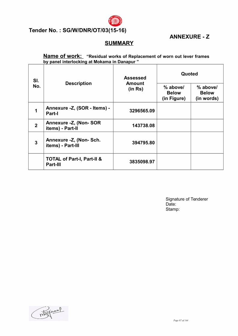
Tender No. : SG/W/DNR/OT/03(15-16)ANNEXURE - Z
SUMMARY
Name of work: “Residual works of Replacement of worn out lever framesby panel interlocking at Mokama in Danapur ”
Sl. No.
DescriptionAssessedAmount (in Rs)
Quoted
% above/Below
(in Figure)
% above/Below
(in words)
1Annexure -Z, (SOR - Items) -Part-I
3296565.09
2Annexure -Z, (Non- SOR items) - Part-II
143738.08
3Annexure -Z, (Non- Sch. items) - Part-III
394795.80
TOTAL of Part-I, Part-II & Part-III
3835098.97
Signature of TendererDate:Stamp:
Page 87 of 144

TENDER NO: SG/W/DNR/OT/03(15-16)SOR ITEMS:
Name of work: ““Residual works of Replacement of worn out lever frames bypanel interlocking at Mokama in Danapur ” .
ANNEXURE - Z, Part-I
S.N. Description of work UnitTotalQty
Rate Amount
GROUP-A
CABLE LAYING
1 Excavation of Trench in all kinds of soil
and
refilling of trenches (1.2 Mtr Depth, 300
mm
Width) I) Crosswise 2nd class bricks (8 per mtr.) Mtr. 0 30.37 0.00 including cost of bricks. ii) Lengthwise 2nd class bricks (4 per mtr.) Mtr. 0 22.45 0.00 Including cost of bricks. iii) Without bricks Mtr. 8000 14.52 116160.00 2 Excavation of trench in all kinds of soil and refilling of trenches (1 Mtr. Depth 300 mm width) I) With 2nd class bricks laid crosswise (8 Mtr. 0 27.73 0.00 bricks per mtr.) including cost of bricks. ii) With 2nd class bricks laid lengthwise Mtr. 0 19.81 0.00 over the cable (4 bricks per mtr.) including cost of bricks. iii) Without bricks Mtr. 0 11.88 0.00 3 Excavation of trench in all kinds of soil and refilling of trenches (0.5 Mtr. Depth 0.3 Mtr. width) I) With 2nd class bricks, Lengthwise (4 Mtr. 0 18.49 0.00
Page 88 of 144
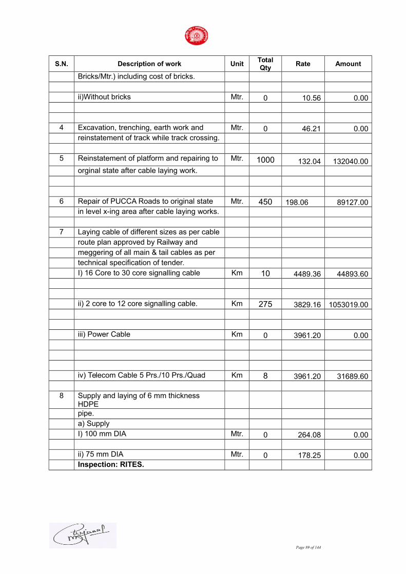
S.N. Description of work UnitTotalQty
Rate Amount
Bricks/Mtr.) including cost of bricks. ii)Without bricks Mtr. 0 10.56 0.00 4 Excavation, trenching, earth work and Mtr. 0 46.21 0.00 reinstatement of track while track crossing. 5 Reinstatement of platform and repairing to Mtr. 1000 132.04 132040.00 orginal state after cable laying work. 6 Repair of PUCCA Roads to original state Mtr. 450 198.06 89127.00 in level x-ing area after cable laying works. 7 Laying cable of different sizes as per cable route plan approved by Railway and meggering of all main & tail cables as per technical specification of tender. I) 16 Core to 30 core signalling cable Km 10 4489.36 44893.60 ii) 2 core to 12 core signalling cable. Km 275 3829.16 1053019.00 iii) Power Cable Km 0 3961.20 0.00 iv) Telecom Cable 5 Prs./10 Prs./Quad Km 8 3961.20 31689.60 8 Supply and laying of 6 mm thickness
HDPE
pipe. a) Supply I) 100 mm DIA Mtr. 0 264.08 0.00 ii) 75 mm DIA Mtr. 0 178.25 0.00 Inspection: RITES.
Page 89 of 144

S.N. Description of work UnitTotalQty
Rate Amount
b) Execution I) 100 mm DIA Mtr. 0 22.45 0.00 ii)75 mm DIA Mtr. 0 22.45 0.009 Supply and fixing of G.I. Pipe with
threaded
collars of 100 mm nominal bore specn. No. IS 1239 medium grade.Perforated of required length on bridge / below metalled road/ L -Xing /Culvert as per technical specification of tender. a) Supply portion for the G. I. Pipe &
collars.Mtr. 0 442.33 0.00
Inspection: RITES. b) Execution with remaining miscelleneous Mtr. 250 19.81 4952.50 materials
10 Supply and installation of RCC Pipe (Dia 150mm internal) 2m Length under track crossing (one track) as per IS - specification IS - 458 / 71 (Latest). a) Supply No. 0 264.08 0.00 Inspection: RITES. b) Execution Track 0 39.61 0.00
11 Supply of galvanised iron trunking with cover of same materials as ser DRG. No. SGW/MGS/C7/91 and fixing on girder bridges including supply of channel, angle iron, bracket units, nuts and bolts of proper size & fitting of support at an interval of 1mtr including laying of cables inside the trough & filling with bitumen compound as per spec. no. IRS-TC-25/76 after cable is laid. Bitumen compound and other
materials
as required for the work shall be supplied by the contractor. a) Supply portion Mtr 0 713.02 0.00 Inspection: RITES.
Page 90 of 144
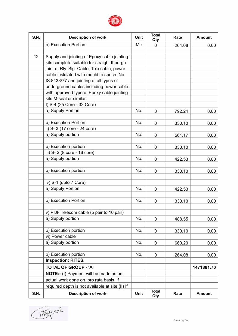
S.N. Description of work UnitTotalQty
Rate Amount
b) Execution Portion Mtr 0 264.08 0.00
12 Supply and jointing of Epoxy cable jointing kits complete suitable for straight thourgh joint of Rly. Sig. Cable, Tele cable, power cable inslulated with mould to specn. No. IS:8438/77 and jointing of all types of underground cables including power cable with approved type of Epoxy cable jointing kits M-seal or similar. I) S-4 (25 Core - 32 Core) a) Supply Portion No. 0 792.24 0.00 b) Execution Portion No. 0 330.10 0.00 ii) S- 3 (17 core - 24 core) a) Supply portion No. 0 561.17 0.00 b) Execution portion No. 0 330.10 0.00 iii) S- 2 (8 core - 16 core) a) Supply portion No. 0 422.53 0.00 b) Execution portion No. 0 330.10 0.00 iv) S-1 (upto 7 Core) a) Supply Portion No. 0 422.53 0.00 b) Execution Portion No. 0 330.10 0.00 v) PIJF Telecom cable (5 pair to 10 pair) a) Supply portion No. 0 488.55 0.00 b) Execution portion No. 0 330.10 0.00 vi) Power cable a) Supply portion No. 0 660.20 0.00 b) Execution portion No. 0 264.08 0.00 Inspection: RITES.
TOTAL OF GROUP - 'A' 1471881.70
NOTE:- (I) Payment will be made as per
actual work done on pro rata basis, if
required depth is not available at site (II) If
S.N. Description of work UnitTotalQty
Rate Amount
Page 91 of 144
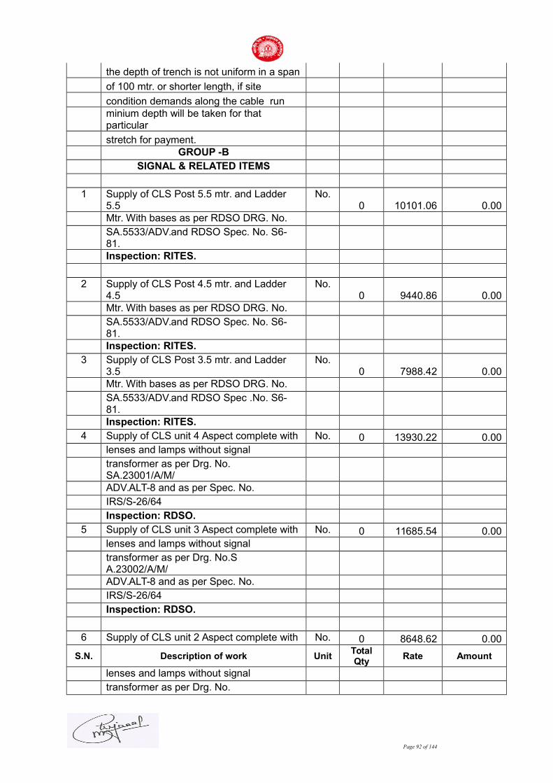
the depth of trench is not uniform in a span
of 100 mtr. or shorter length, if site
condition demands along the cable run
minium depth will be taken for that particular
stretch for payment. GROUP -B SIGNAL & RELATED ITEMS 1 Supply of CLS Post 5.5 mtr. and Ladder
5.5No.
0 10101.06 0.00 Mtr. With bases as per RDSO DRG. No. SA.5533/ADV.and RDSO Spec. No. S6-
81.
Inspection: RITES. 2 Supply of CLS Post 4.5 mtr. and Ladder
4.5No.
0 9440.86 0.00 Mtr. With bases as per RDSO DRG. No. SA.5533/ADV.and RDSO Spec. No. S6-
81.
Inspection: RITES. 3 Supply of CLS Post 3.5 mtr. and Ladder
3.5No.
0 7988.42 0.00 Mtr. With bases as per RDSO DRG. No. SA.5533/ADV.and RDSO Spec .No. S6-
81.
Inspection: RITES. 4 Supply of CLS unit 4 Aspect complete with No. 0 13930.22 0.00 lenses and lamps without signal transformer as per Drg. No.
SA.23001/A/M/
ADV.ALT-8 and as per Spec. No. IRS/S-26/64 Inspection: RDSO. 5 Supply of CLS unit 3 Aspect complete with No. 0 11685.54 0.00 lenses and lamps without signal transformer as per Drg. No.S
A.23002/A/M/
ADV.ALT-8 and as per Spec. No. IRS/S-26/64 Inspection: RDSO. 6 Supply of CLS unit 2 Aspect complete with No. 0 8648.62 0.00
S.N. Description of work UnitTotalQty
Rate Amount
lenses and lamps without signal transformer as per Drg. No.
Page 92 of 144
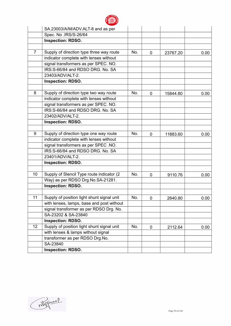
SA.23003/A/M/ADV.ALT-8 and as per Spec. No .IRS/S-26/64 Inspection: RDSO. 7 Supply of direction type three way route No. 0 23767.20 0.00 indicator complete with lenses without signal transformers as per SPEC. NO. IRS:S-66/84 and RDSO DRG. No. SA 23403/ADV/ALT-2. Inspection: RDSO. 8 Supply of direction type two way route No. 0 15844.80 0.00 indicator complete with lenses without signal transformers as per SPEC. NO. IRS:S-66/84 and RDSO DRG. No. SA 23402/ADV/ALT-2. Inspection: RDSO. 9 Supply of direction type one way route No. 0 11883.60 0.00 indicator complete with lenses without signal transformers as per SPEC .NO. IRS:S-66/84 and RDSO DRG. No. SA 23401/ADV/ALT-2. Inspection: RDSO.
10 Supply of Stencil Type route indicator (2 No. 0 9110.76 0.00 Way) as per RDSO Drg.No.SA-21281. Inspection: RDSO.
11 Supply of position light shunt signal unit No. 0 2640.80 0.00 with lenses, lamps, base and post without signal transformer as per RDSO Drg. No. SA-23202 & SA-23840 Inspection: RDSO.
12 Supply of position light shunt signal unit No. 0 2112.64 0.00 with lenses & lamps without signal transformer as per RDSO Drg.No. SA-23840 Inspection: RDSO.
Page 93 of 144
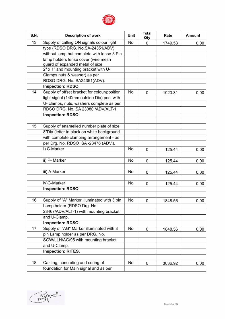
S.N. Description of work UnitTotalQty
Rate Amount
13 Supply of calling ON signals colour light No. 0 1749.53 0.00 type (RDSO DRG. No.SA-24351/ADV) without lamp but complete with lense 3 Pin lamp holders lense cover (wire mesh
guard of expanded metal of size
2" x 1" and mounting bracket with U- Clamps nuts & washer) as per RDSO DRG. No. SA24351(ADV). Inspection: RDSO.
14 Supply of offset bracket for colour/position No. 0 1023.31 0.00 light signal (140mm outside Dia) post with U- clamps, nuts, washers complete as per RDSO DRG. No. SA 23080 /ADV/ALT-1. Inspection: RDSO.
15 Supply of enamelled number plate of size 8"Dia (letter in black on white background with complete clamping arrangement - as per Drg. No. RDSO SA -23476 (ADV.). I) C-Marker No. 0 125.44 0.00 ii) P- Marker No. 0 125.44 0.00 iii) A-Marker No. 0 125.44 0.00 iv)G-Marker No. 0 125.44 0.00 Inspection: RDSO.
16 Supply of "A" Marker illuminated with 3 pin No. 0 1848.56 0.00 Lamp holder (RDSO Drg. No. 23467/ADV/ALT-1) with mounting bracket and U-Clamp. Inspection: RDSO.
17 Supply of "AG" Marker illuminated with 3 No. 0 1848.56 0.00 pin Lamp holder as per DRG. No.
SGW/LLH/AG/95 with mounting bracket and U-Clamp. Inspection: RITES.
18 Casting, concreting and curing of No. 0 3036.92 0.00 foundation for Main signal and as per
Page 94 of 144
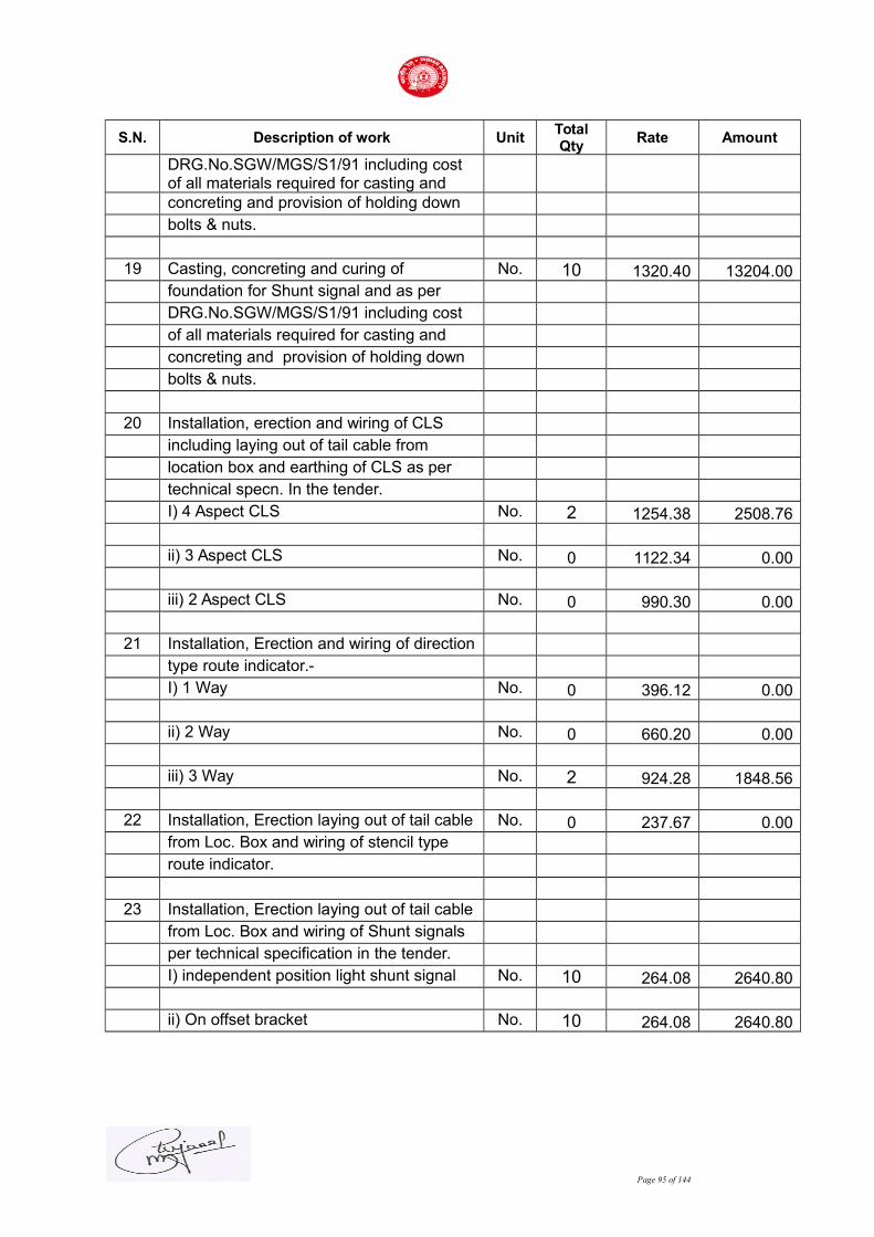
S.N. Description of work UnitTotalQty
Rate Amount
DRG.No.SGW/MGS/S1/91 including cost of all materials required for casting and
concreting and provision of holding down bolts & nuts.
19 Casting, concreting and curing of No. 10 1320.40 13204.00 foundation for Shunt signal and as per DRG.No.SGW/MGS/S1/91 including cost of all materials required for casting and concreting and provision of holding down bolts & nuts.
20 Installation, erection and wiring of CLS including laying out of tail cable from location box and earthing of CLS as per technical specn. In the tender. I) 4 Aspect CLS No. 2 1254.38 2508.76 ii) 3 Aspect CLS No. 0 1122.34 0.00 iii) 2 Aspect CLS No. 0 990.30 0.00
21 Installation, Erection and wiring of direction type route indicator.- I) 1 Way No. 0 396.12 0.00 ii) 2 Way No. 0 660.20 0.00 iii) 3 Way No. 2 924.28 1848.56
22 Installation, Erection laying out of tail cable No. 0 237.67 0.00 from Loc. Box and wiring of stencil type route indicator.
23 Installation, Erection laying out of tail cable from Loc. Box and wiring of Shunt signals per technical specification in the tender. I) independent position light shunt signal No. 10 264.08 2640.80 ii) On offset bracket No. 10 264.08 2640.80
Page 95 of 144
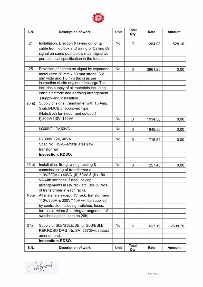
S.N. Description of work UnitTotalQty
Rate Amount
24 Installation, Erection & laying out of tail No. 2 264.08 528.16 cable from loc.box and wiring of Calling On signal on same post below main signal as per technical specification in the tender.
25 Provision of screen on signal by expanded No. 0 3961.20 0.00 metal (size 20 mm x 60 mm strand, 3.2
mm wide and 1.6 mm thick) as per
instruction of site engineer incharge.This includes supply of all materials including earth electrode and earthing arrangement (supply and installation)
26 a) Supply of signal transformer with 15 Amp. Switch/MCB of approved type. (Note:Both for indoor and outdoor) I) 300V/110V, 150VA No. 0 1914.58 0.00 ii)300V/110V,60VA No. 0 1848.56 0.00 iii) 300V/12V, 40VA No. 0 1716.52 0.00 Spec.No.IRS-S-92/93(Latest) for transformer Inspection: RDSO.
26 b) Installation, fixing, wiring, testing & No. 0 257.48 0.00 commissioning of transformer a) 110V/300V-(I) 40VA, (II) 60VA & (iii) 150 VA with switches, fuses, locking arrangements in HV rack etc. (for 30 Nos. of transformer in each rack).
Note All materials except HV rack, transformers 110V/300V & 300V/110V will be supplied by contractor including switches, fuses, terminals, wires & locking arrangement of switches against item no.26b).
27a) Supply of SLB/BSLB/SB for SLB/BSLB No. 4 627.19 2508.76 REF.RDSO DRG. No.SA- 2373(with latest amendment). Inspection: RDSO.
S.N. Description of work UnitTotalQty
Rate Amount
Page 96 of 144
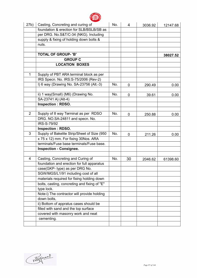
27b) Casting, Concreting and curing of No. 4 3036.92 12147.68 foundation & erection for SLB/BSLB/SB as per DRG. No.S&T/C-34 (NKG). Including supply & fixing of holding down bolts & nuts.
TOTAL OF GROUP- 'B' 38027.52 GROUP C LOCATION BOXES 1 Supply of PBT ARA terminal block as per IRS Specn. No. IRS:S-75/2006 (Rev-2) I) 6 way (Drawing No. SA-23756 (Alt.-3) No. 0 290.49 0.00 ii) 1 way(Small) (M6) (Drawing No. No. 0 39.61 0.00 SA-23741 A) (Alt-4) Inspection : RDSO. 2 Supply of 8 way Terminal as per RDSO No. 0 250.88 0.00 DRG. NO.SA-24811 and specn. No. IRS-S-79/92 Inspection : RDSO. 3 Supply of Bakelite Strip/Sheet of Size (950 No. 0 211.26 0.00 x 75 x 12) mm. For fixing 30Nos. ARA terminals/Fuse base terminals/Fuse base. Inspection - Consignee. 4 Casting, Concreting and Curing of No. 30 2046.62 61398.60 foundation and erection for full apparatus case(GKP- type) as per DRG No. SGW/MGS/L1/91 including cost of all materials required for fixing holding down bolts, casting, concreting and fixing of "E" type lock. Note:i) The contractor will provide holding down bolts, ii) Bottom of appratus cases should be filled with sand and the top surface covered with masonry work and neat cementing.
Page 97 of 144
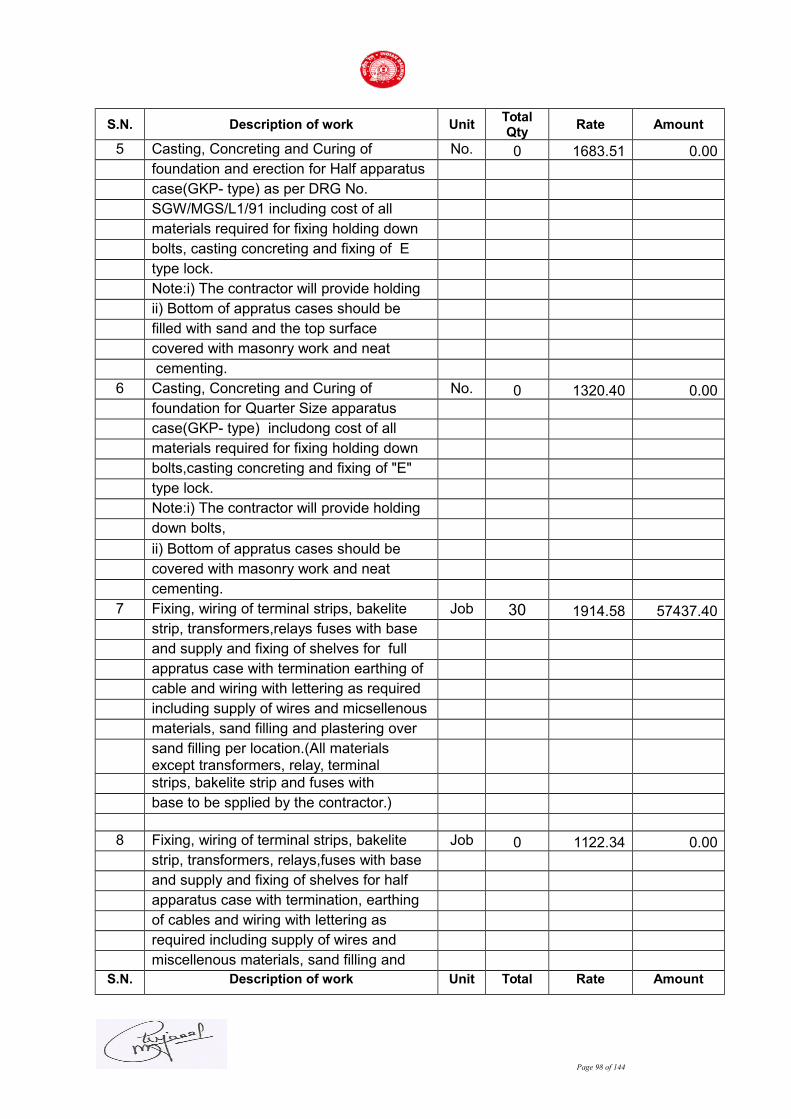
S.N. Description of work UnitTotalQty
Rate Amount
5 Casting, Concreting and Curing of No. 0 1683.51 0.00 foundation and erection for Half apparatus case(GKP- type) as per DRG No. SGW/MGS/L1/91 including cost of all materials required for fixing holding down bolts, casting concreting and fixing of E type lock. Note:i) The contractor will provide holding ii) Bottom of appratus cases should be filled with sand and the top surface covered with masonry work and neat cementing. 6 Casting, Concreting and Curing of No. 0 1320.40 0.00 foundation for Quarter Size apparatus case(GKP- type) includong cost of all materials required for fixing holding down bolts,casting concreting and fixing of "E" type lock. Note:i) The contractor will provide holding down bolts, ii) Bottom of appratus cases should be covered with masonry work and neat cementing. 7 Fixing, wiring of terminal strips, bakelite Job 30 1914.58 57437.40 strip, transformers,relays fuses with base and supply and fixing of shelves for full appratus case with termination earthing of cable and wiring with lettering as required including supply of wires and micsellenous materials, sand filling and plastering over sand filling per location.(All materials
except transformers, relay, terminal
strips, bakelite strip and fuses with base to be spplied by the contractor.) 8 Fixing, wiring of terminal strips, bakelite Job 0 1122.34 0.00 strip, transformers, relays,fuses with base and supply and fixing of shelves for half apparatus case with termination, earthing of cables and wiring with lettering as required including supply of wires and miscellenous materials, sand filling and
S.N. Description of work Unit Total Rate Amount
Page 98 of 144
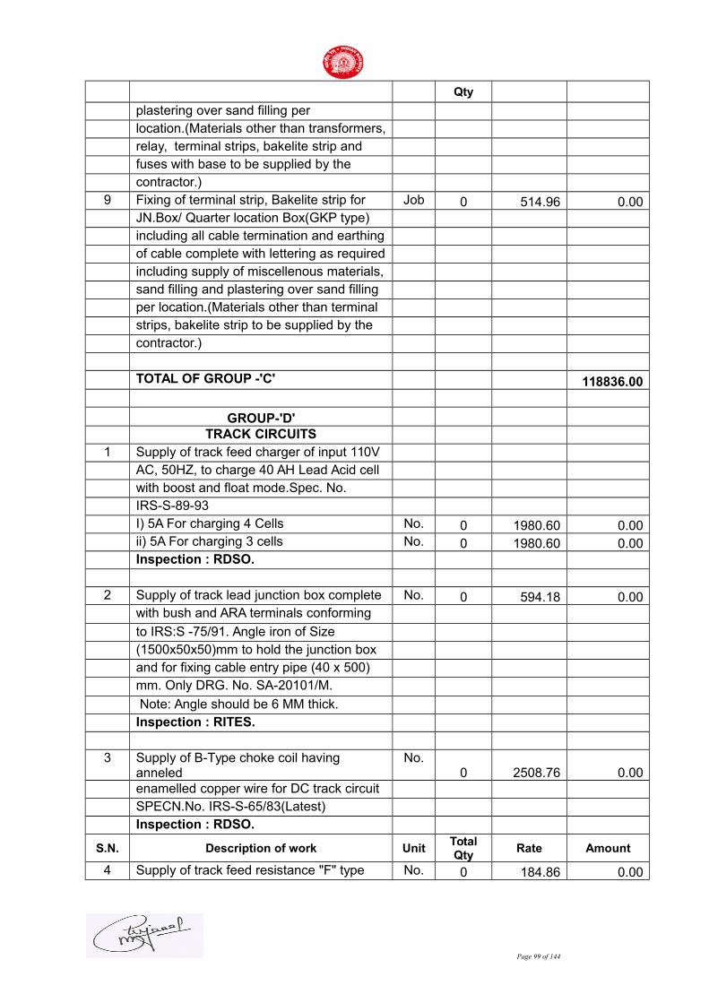
Qty
plastering over sand filling per location.(Materials other than transformers, relay, terminal strips, bakelite strip and fuses with base to be supplied by the contractor.) 9 Fixing of terminal strip, Bakelite strip for Job 0 514.96 0.00 JN.Box/ Quarter location Box(GKP type) including all cable termination and earthing of cable complete with lettering as required including supply of miscellenous materials, sand filling and plastering over sand filling per location.(Materials other than terminal strips, bakelite strip to be supplied by the contractor.) TOTAL OF GROUP -'C' 118836.00
GROUP-'D' TRACK CIRCUITS 1 Supply of track feed charger of input 110V AC, 50HZ, to charge 40 AH Lead Acid cell with boost and float mode.Spec. No. IRS-S-89-93 I) 5A For charging 4 Cells No. 0 1980.60 0.00 ii) 5A For charging 3 cells No. 0 1980.60 0.00 Inspection : RDSO. 2 Supply of track lead junction box complete No. 0 594.18 0.00 with bush and ARA terminals conforming to IRS:S -75/91. Angle iron of Size (1500x50x50)mm to hold the junction box and for fixing cable entry pipe (40 x 500) mm. Only DRG. No. SA-20101/M. Note: Angle should be 6 MM thick. Inspection : RITES. 3 Supply of B-Type choke coil having
anneledNo.
0 2508.76 0.00 enamelled copper wire for DC track circuit SPECN.No. IRS-S-65/83(Latest) Inspection : RDSO.
S.N. Description of work UnitTotalQty
Rate Amount
4 Supply of track feed resistance "F" type No. 0 184.86 0.00
Page 99 of 144
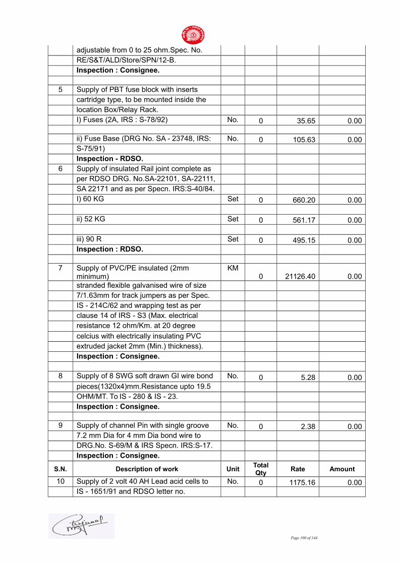
adjustable from 0 to 25 ohm.Spec. No. RE/S&T/ALD/Store/SPN/12-B. Inspection : Consignee. 5 Supply of PBT fuse block with inserts cartridge type, to be mounted inside the location Box/Relay Rack. I) Fuses (2A, IRS : S-78/92) No. 0 35.65 0.00 ii) Fuse Base (DRG No. SA - 23748, IRS: No. 0 105.63 0.00 S-75/91) Inspection - RDSO. 6 Supply of insulated Rail joint complete as per RDSO DRG. No.SA-22101, SA-22111, SA 22171 and as per Specn. IRS:S-40/84. I) 60 KG Set 0 660.20 0.00 ii) 52 KG Set 0 561.17 0.00 iii) 90 R Set 0 495.15 0.00 Inspection : RDSO. 7 Supply of PVC/PE insulated (2mm
minimum)KM
0 21126.40 0.00 stranded flexible galvanised wire of size 7/1.63mm for track jumpers as per Spec. IS - 214C/62 and wrapping test as per clause 14 of IRS - S3 (Max. electrical resistance 12 ohm/Km. at 20 degree celcius with electrically insulating PVC extruded jacket 2mm (Min.) thickness). Inspection : Consignee. 8 Supply of 8 SWG soft drawn GI wire bond No. 0 5.28 0.00 pieces(1320x4)mm.Resistance upto 19.5 OHM/MT. To IS - 280 & IS - 23. Inspection : Consignee. 9 Supply of channel Pin with single groove No. 0 2.38 0.00 7.2 mm Dia for 4 mm Dia bond wire to DRG.No. S-69/M & IRS Specn. IRS:S-17. Inspection : Consignee.
S.N. Description of work UnitTotalQty
Rate Amount
10 Supply of 2 volt 40 AH Lead acid cells to No. 0 1175.16 0.00 IS - 1651/91 and RDSO letter no.
Page 100 of 144
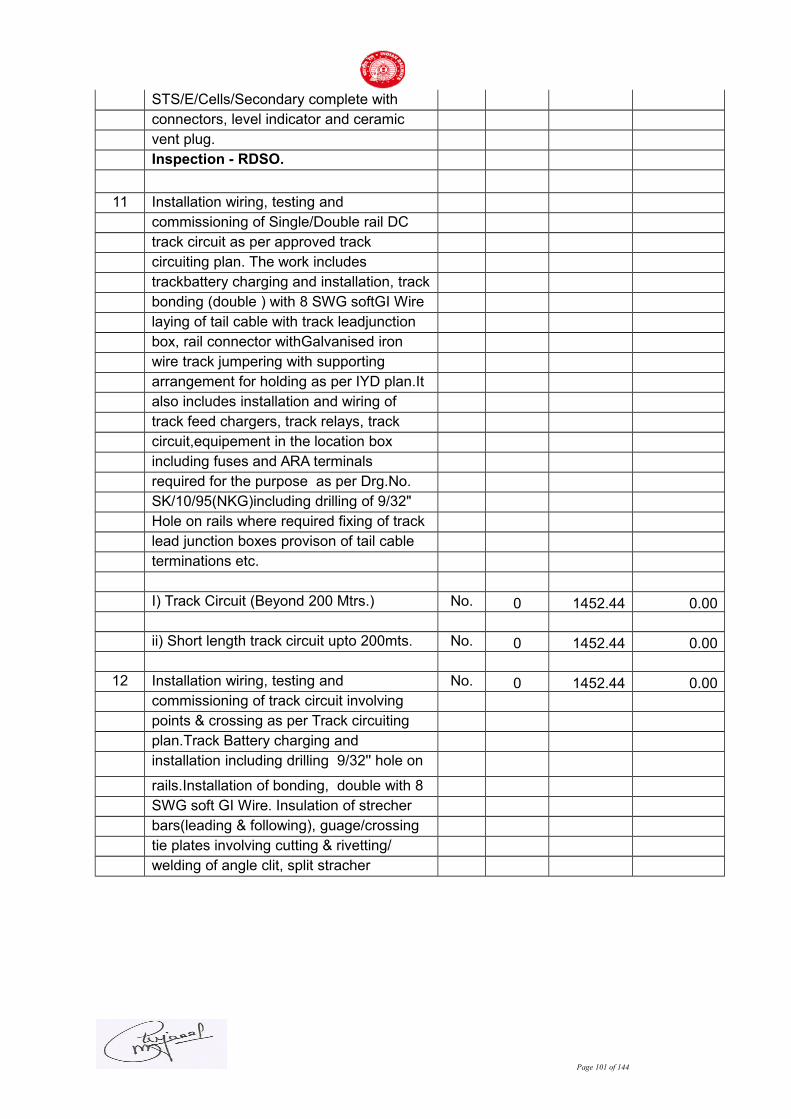
STS/E/Cells/Secondary complete with connectors, level indicator and ceramic vent plug. Inspection - RDSO.
11 Installation wiring, testing and commissioning of Single/Double rail DC track circuit as per approved track circuiting plan. The work includes trackbattery charging and installation, track bonding (double ) with 8 SWG softGI Wire laying of tail cable with track leadjunction box, rail connector withGalvanised iron wire track jumpering with supporting arrangement for holding as per IYD plan.It also includes installation and wiring of track feed chargers, track relays, track circuit,equipement in the location box including fuses and ARA terminals required for the purpose as per Drg.No. SK/10/95(NKG)including drilling of 9/32" Hole on rails where required fixing of track lead junction boxes provison of tail cable terminations etc. I) Track Circuit (Beyond 200 Mtrs.) No. 0 1452.44 0.00 ii) Short length track circuit upto 200mts. No. 0 1452.44 0.00
12 Installation wiring, testing and No. 0 1452.44 0.00 commissioning of track circuit involving points & crossing as per Track circuiting plan.Track Battery charging and installation including drilling 9/32'' hole on rails.Installation of bonding, double with 8 SWG soft GI Wire. Insulation of strecher bars(leading & following), guage/crossing tie plates involving cutting & rivetting/ welding of angle clit, split stracher
Page 101 of 144
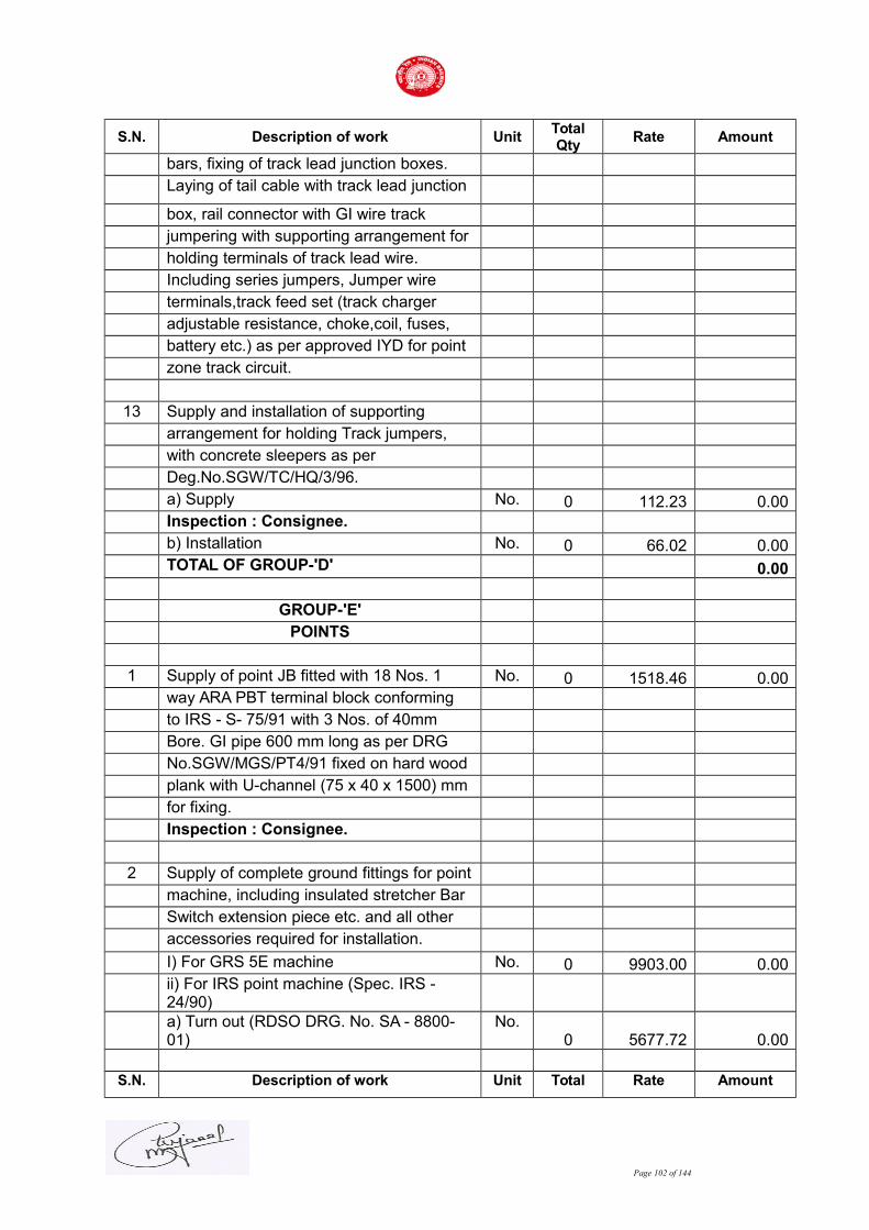
S.N. Description of work UnitTotalQty
Rate Amount
bars, fixing of track lead junction boxes. Laying of tail cable with track lead junction
box, rail connector with GI wire track jumpering with supporting arrangement for holding terminals of track lead wire. Including series jumpers, Jumper wire terminals,track feed set (track charger adjustable resistance, choke,coil, fuses, battery etc.) as per approved IYD for point zone track circuit.
13 Supply and installation of supporting arrangement for holding Track jumpers, with concrete sleepers as per Deg.No.SGW/TC/HQ/3/96. a) Supply No. 0 112.23 0.00 Inspection : Consignee. b) Installation No. 0 66.02 0.00 TOTAL OF GROUP-'D' 0.00 GROUP-'E' POINTS 1 Supply of point JB fitted with 18 Nos. 1 No. 0 1518.46 0.00 way ARA PBT terminal block conforming to IRS - S- 75/91 with 3 Nos. of 40mm Bore. GI pipe 600 mm long as per DRG No.SGW/MGS/PT4/91 fixed on hard wood plank with U-channel (75 x 40 x 1500) mm for fixing. Inspection : Consignee. 2 Supply of complete ground fittings for point machine, including insulated stretcher Bar Switch extension piece etc. and all other accessories required for installation. I) For GRS 5E machine No. 0 9903.00 0.00 ii) For IRS point machine (Spec. IRS -
24/90)
a) Turn out (RDSO DRG. No. SA - 8800-
01)No.
0 5677.72 0.00
S.N. Description of work Unit Total Rate Amount
Page 102 of 144
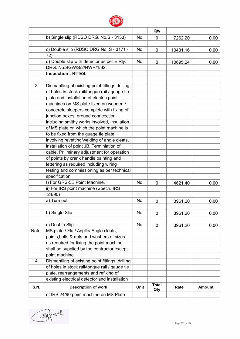
Qty
b) Single slip (RDSO DRG. No.S - 3153) No. 0 7262.20 0.00 c) Double slip (RDSO DRG No. S - 3171 - No. 0 10431.16 0.00 72) d) Double slip with detector as per E.Rly. No. 0 10695.24 0.00
DRG. No.SGW/S/2/HWH/1/92. Inspection : RITES. 3 Dismantling of existing point fittings drilling of holes in stock rail/tongue rail / guage tie plate and installation of electric point machines on MS plate fixed on wooden / concerete sleepers complete with fixing of junction boxes, ground conncection including smithy works involved, insulation of MS plate on which the point machine is to be fixed from the guage tie plate involving revetting/welding of angle cleats, installation of point JB, Terminiation of cable, Priliminary adjustment for operation of points by crank handle painting and lettering as required including wiring testing and commissioning as per technical specification. I) For GRS-5E Point Machine. No. 0 4621.40 0.00 ii) For IRS point machine (Spech. IRS 24/90) a) Turn out No. 0 3961.20 0.00 b) Single Slip No. 0 3961.20 0.00 c) Double Slip No. 0 3961.20 0.00
Note: MS plate / Flat/ Anglle/ Angle cleats, paints,bolts & nuts and washers of sizes as required for fixing the point machine shall be supplied by the contractor except point machine. 4 Dismantling of existing point fittings, drilling of holes in stock rail/tongue rail / gauge tie plate, rearrangements and refixing of
existing electrical detector and installation
S.N. Description of work UnitTotalQty
Rate Amount
of IRS 24/90 point machine on MS Plate
Page 103 of 144
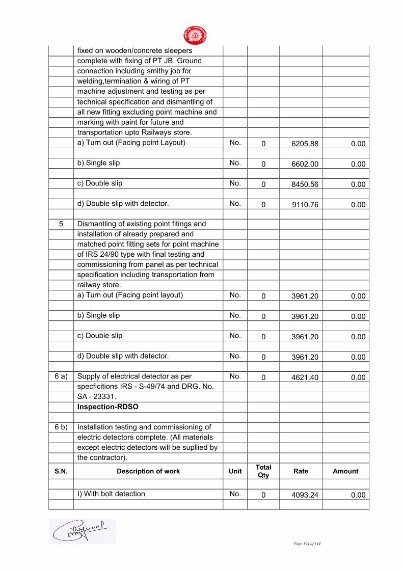
fixed on wooden/concrete sleepers complete with fixing of PT JB. Ground connection including smithy job for welding,termination & wiring of PT machine adjustment and testing as per technical specification and dismantling of all new fitting excluding point machine and marking with paint for future and transportation upto Railways store. a) Turn out (Facing point Layout) No. 0 6205.88 0.00 b) Single slip No. 0 6602.00 0.00 c) Double slip No. 0 8450.56 0.00 d) Double slip with detector. No. 0 9110.76 0.00 5 Dismantling of existing point fitings and installation of already prepared and matched point fitting sets for point machine of IRS 24/90 type with final testing and commissioning from panel as per technical specification including transportation from railway store. a) Turn out (Facing point layout) No. 0 3961.20 0.00 b) Single slip No. 0 3961.20 0.00 c) Double slip No. 0 3961.20 0.00 d) Double slip with detector. No. 0 3961.20 0.00
6 a) Supply of electrical detector as per No. 0 4621.40 0.00
specficitions IRS - S-49/74 and DRG. No. SA - 23331. Inspection-RDSO
6 b) Installation testing and commissioning of electric detectors complete. (All materials except electric detectors will be supllied by the contractor).
S.N. Description of work UnitTotalQty
Rate Amount
I) With bolt detection No. 0 4093.24 0.00
Page 104 of 144
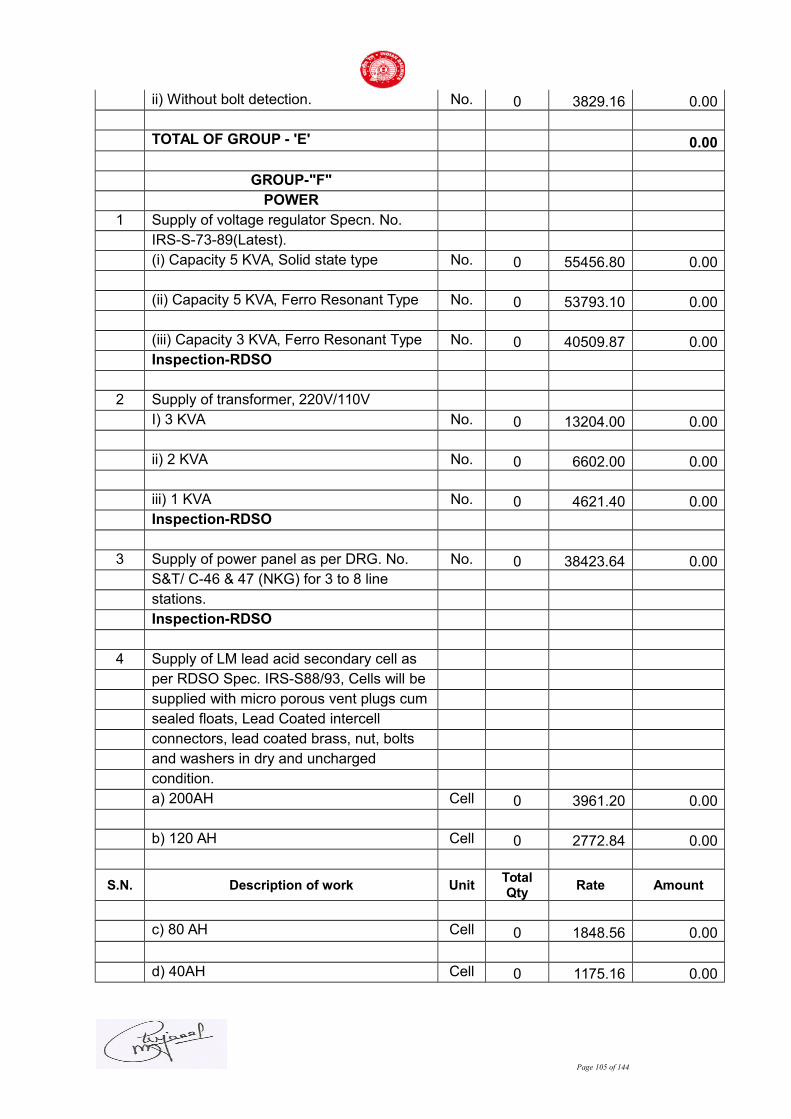
ii) Without bolt detection. No. 0 3829.16 0.00 TOTAL OF GROUP - 'E' 0.00 GROUP-"F" POWER 1 Supply of voltage regulator Specn. No. IRS-S-73-89(Latest). (i) Capacity 5 KVA, Solid state type No. 0 55456.80 0.00 (ii) Capacity 5 KVA, Ferro Resonant Type No. 0 53793.10 0.00 (iii) Capacity 3 KVA, Ferro Resonant Type No. 0 40509.87 0.00 Inspection-RDSO 2 Supply of transformer, 220V/110V I) 3 KVA No. 0 13204.00 0.00 ii) 2 KVA No. 0 6602.00 0.00 iii) 1 KVA No. 0 4621.40 0.00 Inspection-RDSO 3 Supply of power panel as per DRG. No. No. 0 38423.64 0.00 S&T/ C-46 & 47 (NKG) for 3 to 8 line stations. Inspection-RDSO 4 Supply of LM lead acid secondary cell as per RDSO Spec. IRS-S88/93, Cells will be supplied with micro porous vent plugs cum sealed floats, Lead Coated intercell connectors, lead coated brass, nut, bolts and washers in dry and uncharged condition. a) 200AH Cell 0 3961.20 0.00 b) 120 AH Cell 0 2772.84 0.00
S.N. Description of work UnitTotalQty
Rate Amount
c) 80 AH Cell 0 1848.56 0.00 d) 40AH Cell 0 1175.16 0.00
Page 105 of 144
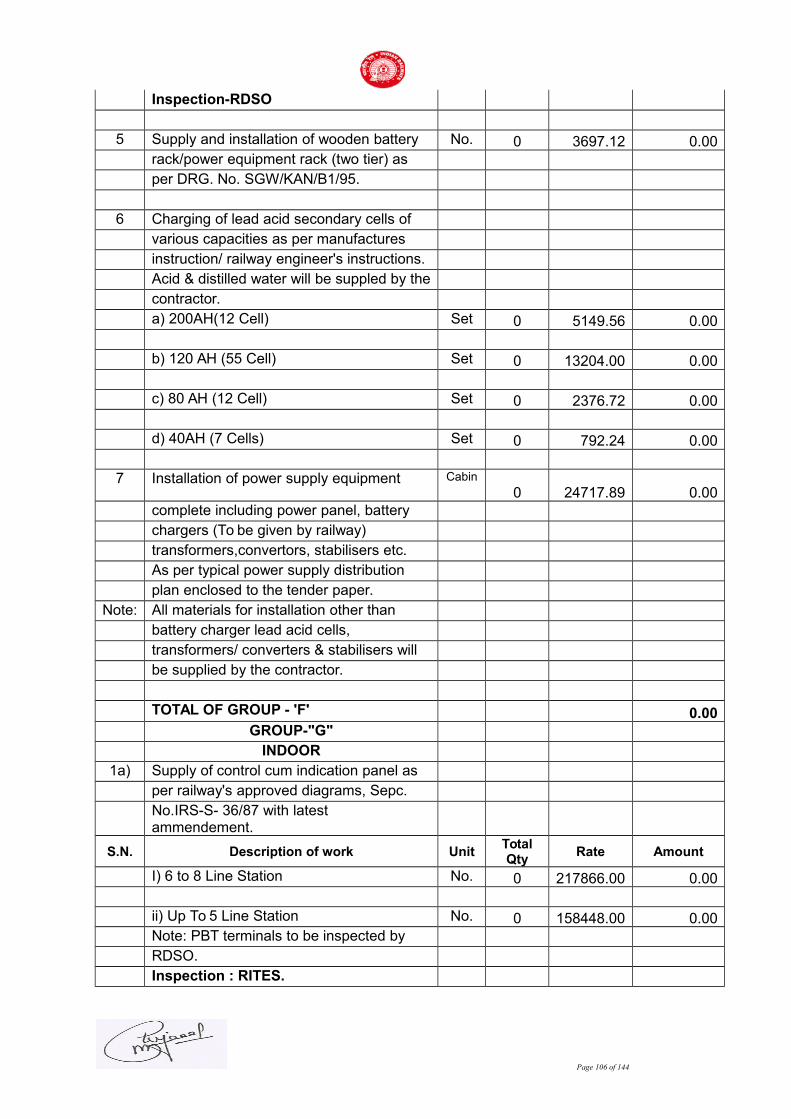
Inspection-RDSO 5 Supply and installation of wooden battery No. 0 3697.12 0.00 rack/power equipment rack (two tier) as per DRG. No. SGW/KAN/B1/95. 6 Charging of lead acid secondary cells of various capacities as per manufactures instruction/ railway engineer's instructions. Acid & distilled water will be suppled by the contractor. a) 200AH(12 Cell) Set 0 5149.56 0.00 b) 120 AH (55 Cell) Set 0 13204.00 0.00 c) 80 AH (12 Cell) Set 0 2376.72 0.00 d) 40AH (7 Cells) Set 0 792.24 0.00 7 Installation of power supply equipment Cabin
0 24717.89 0.00 complete including power panel, battery chargers (To be given by railway) transformers,convertors, stabilisers etc. As per typical power supply distribution plan enclosed to the tender paper.
Note: All materials for installation other than battery charger lead acid cells, transformers/ converters & stabilisers will be supplied by the contractor. TOTAL OF GROUP - 'F' 0.00 GROUP-"G" INDOOR
1a) Supply of control cum indication panel as per railway's approved diagrams, Sepc. No.IRS-S- 36/87 with latest
ammendement.
S.N. Description of work UnitTotalQty
Rate Amount
I) 6 to 8 Line Station No. 0 217866.00 0.00 ii) Up To 5 Line Station No. 0 158448.00 0.00 Note: PBT terminals to be inspected by RDSO. Inspection : RITES.
Page 106 of 144
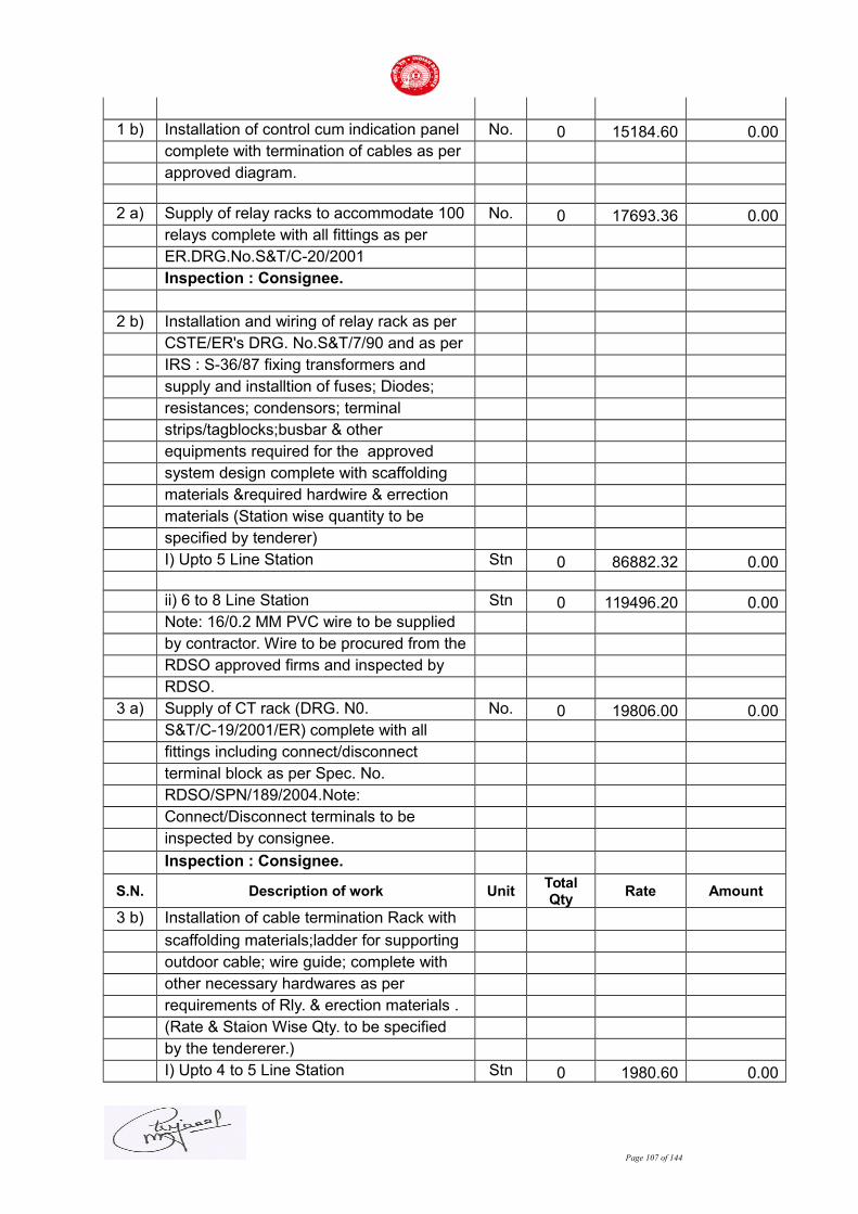
1 b) Installation of control cum indication panel No. 0 15184.60 0.00
complete with termination of cables as per approved diagram.
2 a) Supply of relay racks to accommodate 100 No. 0 17693.36 0.00 relays complete with all fittings as per ER.DRG.No.S&T/C-20/2001 Inspection : Consignee.
2 b) Installation and wiring of relay rack as per CSTE/ER's DRG. No.S&T/7/90 and as per IRS : S-36/87 fixing transformers and supply and installtion of fuses; Diodes; resistances; condensors; terminal strips/tagblocks;busbar & other equipments required for the approved system design complete with scaffolding materials &required hardwire & errection materials (Station wise quantity to be specified by tenderer) I) Upto 5 Line Station Stn 0 86882.32 0.00 ii) 6 to 8 Line Station Stn 0 119496.20 0.00 Note: 16/0.2 MM PVC wire to be supplied by contractor. Wire to be procured from the RDSO approved firms and inspected by RDSO.
3 a) Supply of CT rack (DRG. N0. No. 0 19806.00 0.00 S&T/C-19/2001/ER) complete with all fittings including connect/disconnect terminal block as per Spec. No. RDSO/SPN/189/2004.Note:
Connect/Disconnect terminals to be inspected by consignee. Inspection : Consignee.
S.N. Description of work UnitTotalQty
Rate Amount
3 b) Installation of cable termination Rack with scaffolding materials;ladder for supporting outdoor cable; wire guide; complete with other necessary hardwares as per requirements of Rly. & erection materials .
(Rate & Staion Wise Qty. to be specified by the tendererer.) I) Upto 4 to 5 Line Station Stn 0 1980.60 0.00
Page 107 of 144
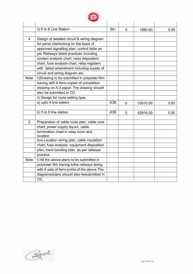
ii) 6 to 8 Line Station Stn 0 1980.60 0.00 4 Design of detailed circuit & wiring diagram for panel interlocking on the basis of approved signalling plan, control table as per Railways latest practices including contact analysis chart, relay disposition chart, fuse analysis chart, relay registers with latest amendment including supply of circuit and wiring diagram etc.
Note (i)Drawing to be submitted in polyester film tracing with 6 ferro copies of completion drawing on A-3 paper. The drawing should also be submitted in CD.
ii) Design for route setting type. a) upto 4 line station JOB 0 33010.00 0.00 b) 5 to 8 line station. JOB 0 52816.00 0.00 5 Preparation of cable route plan, cable core chart, power supply layout, cable termination chart in relay room and
location
box.Location wiring plan, cable insulation chart, fuse analysis, equipment disposition plan, track bonding plan, as per railways practice.
Note I) All the above plans to be submitted in polyester film tracing tothe railways along with 6 sets of ferro prints of the above.The diagrams/plans should also besubmitted in CD.
Page 108 of 144
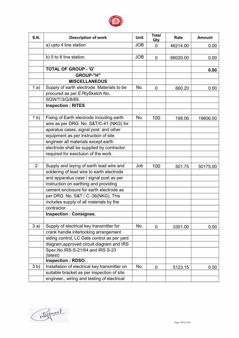
S.N. Description of work UnitTotalQty
Rate Amount
a) upto 4 line station JOB 0 46214.00 0.00 b) 5 to 8 line station. JOB 0 66020.00 0.00 TOTAL OF GROUP - 'G' 0.00 GROUP-"H" MISCELLANEOUS
1 a) Supply of earth electrode. Materials to be No. 0 660.20 0.00 procured as per E.RlySketch No. SGW/T/3/G/8/89. Inspection : RITES
1 b) Fixing of Earth electrode including earth No. 100 198.06 19806.00 wire as per DRG. No. S&T/C-41 (NKG) for aparatus cases, signal post and other equipment as per instruction of site engineer all materials except earth electrode shall be supplied by contractor required for exectuion of the work. 2 Supply and laying of earth lead wire and Job 100 501.75 50175.00 soldering of lead wire to earth electrode and apparatus case / signal post as per instruction on earthing and providing cement enclosure for earth electrode as per DRG. No. S&T / C -36(NKG). This includes supply of all materials by the contractor. Inspection : Consignee.
3 a) Supply of electrical key transmitter for No. 0 3301.00 0.00 crank handle interlocking arrangement siding control, LC Gate control as per yard diagram,approved circuit diagram and IRS Spec.No.IRS-S-21/64.and IRS S-23
(latest)
Inspection : RDSO.
3 b) Installation of electrical key transmitter on No. 0 5123.15 0.00 suitable bracket as per inspection of site engineer., wiring and testing of electrical
Page 109 of 144
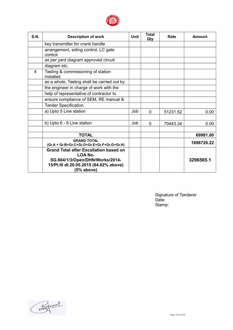
S.N. Description of work UnitTotalQty
Rate Amount
key transmitter for crank handle arrangement, siding control, LC gate
control
as per yard diagram approved circuit diagram etc. 4 Testing & commissioning of station
installed
as a whole, Testing shall be carried out by the engineer in charge of work with the help of representative of contractor to ensure compliance of SEM, RE manual & Tender Specification. a) Upto 5 Line station Job 0 51231.52 0.00 b) Upto 6 - 8 Line station Job 0 70443.34 0.00 TOTAL 69981.00
GRAND TOTAL(Gr.A + Gr.B+Gr.C+Gr.D+Gr.E+Gr.F+Gr.G+Gr.H) 1698726.22
Grand Total after Escallation based onLOA No.
SG.664/1/3/Open/DHN/Works/2014-15/Pt.III dt.20.05.2015 (84.82% above)
(5% above)
3296565.1
Signature of TendererDate:Stamp:
Page 110 of 144
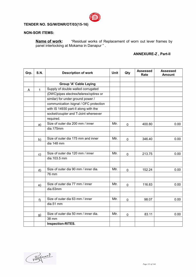
TENDER NO. SG/W/DNR/OT/03(15-16)
NON-SOR ITEMS:
Name of work: “Residual works of Replacement of worn out lever frames bypanel interlocking at Mokama in Danapur ” .
ANNEXURE-Z , Part-II
Grp. S.N. Description of work Unit QtyAssessed
RateAssessedAmount
Group 'A' Cable Laying
A 1 Supply of double walled corrugated
(DWC)pipes electrex/telerex/optirex or
similar) for under ground power /
communication /signal / OFC protection
with IS 14930 part-II along with the
socket/coupler and T-Joint whereever required.
a) Size of outer dia 200 mm / inner Mtr. 0 400.80 0.00
dia.175mm
b) Size of outer dia 175 mm and inner Mtr. 0 346.40 0.00
dia 148 mm
c) Size of outer dia 120 mm / inner Mtr. 0 213.75 0.00
dia.103.5 mm
d) Size of outer dia 90 mm / inner dia. Mtr. 0 152.24 0.00
76 mm
e) Size of outer dia 77 mm / inner Mtr. 0 116.83 0.00
dia.63mm
f) Size of outer dia 63 mm / inner Mtr. 0 98.07 0.00
dia.51 mm
g) Size of outer dia 50 mm / inner dia. Mtr. 0 83.11 0.00
38 mm
Inspection-RITES.
Page 111 of 144
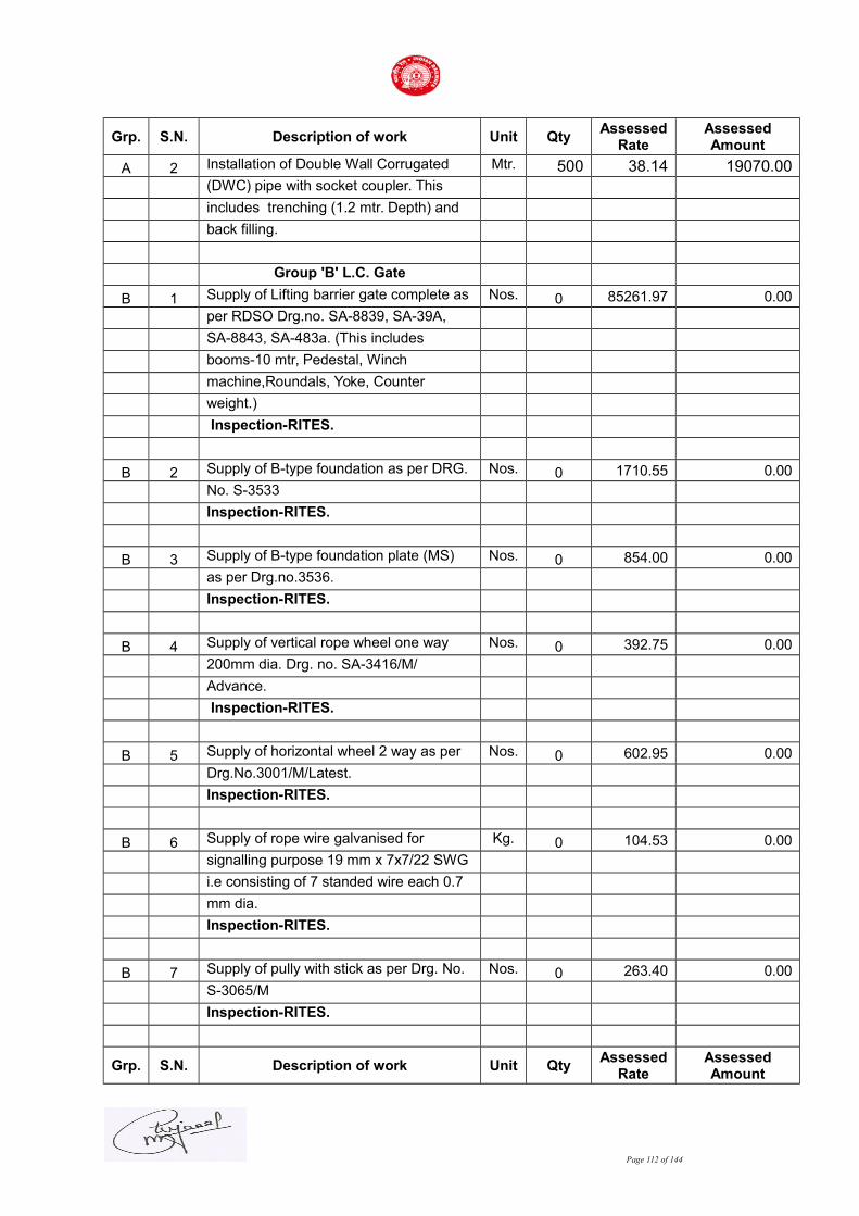
Grp. S.N. Description of work Unit QtyAssessed
RateAssessedAmount
A 2 Installation of Double Wall Corrugated Mtr. 500 38.14 19070.00
(DWC) pipe with socket coupler. This
includes trenching (1.2 mtr. Depth) and
back filling.
Group 'B' L.C. Gate
B 1 Supply of Lifting barrier gate complete as Nos. 0 85261.97 0.00
per RDSO Drg.no. SA-8839, SA-39A,
SA-8843, SA-483a. (This includes
booms-10 mtr, Pedestal, Winch
machine,Roundals, Yoke, Counter
weight.)
Inspection-RITES.
B 2 Supply of B-type foundation as per DRG. Nos. 0 1710.55 0.00
No. S-3533
Inspection-RITES.
B 3 Supply of B-type foundation plate (MS) Nos. 0 854.00 0.00
as per Drg.no.3536.
Inspection-RITES.
B 4 Supply of vertical rope wheel one way Nos. 0 392.75 0.00
200mm dia. Drg. no. SA-3416/M/
Advance.
Inspection-RITES.
B 5 Supply of horizontal wheel 2 way as per Nos. 0 602.95 0.00
Drg.No.3001/M/Latest.
Inspection-RITES.
B 6 Supply of rope wire galvanised for Kg. 0 104.53 0.00
signalling purpose 19 mm x 7x7/22 SWG
i.e consisting of 7 standed wire each 0.7
mm dia.
Inspection-RITES.
B 7 Supply of pully with stick as per Drg. No. Nos. 0 263.40 0.00
S-3065/M
Inspection-RITES.
Grp. S.N. Description of work Unit QtyAssessed
RateAssessedAmount
Page 112 of 144
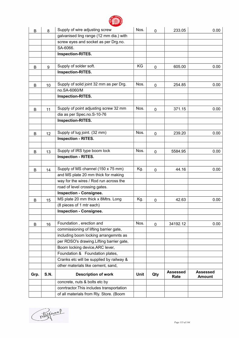
B 8 Supply of wire adjusting screw Nos. 0 233.05 0.00
galvanised ling range (12 mm dia.) with
screw eyes and socket as per Drg.no. SA-6066.
Inspection-RITES.
B 9 Supply of solder soft. KG 0 605.00 0.00
Inspection-RITES.
B 10 Supply of solid joint 32 mm as per Drg. Nos. 0 254.85 0.00
no.SA-6060/M
Inspection-RITES.
B 11 Supply of point adjusting screw 32 mm Nos. 0 371.15 0.00
dia as per Spec.no.S-10-76
Inspection-RITES.
B 12 Supply of lug joint. (32 mm) Nos. 0 239.20 0.00
Inspection - RITES.
B 13 Supply of IRS type boom lock Nos. 0 5584.95 0.00
Inspection - RITES.
B 14 Supply of MS channel (150 x 75 mm) Kg. 0 44.16 0.00
and MS plate 20 mm thick for making
way for the wires / Rod run across the
road of level crossing gates.
Inspection - Consignee.
B 15 MS plate 20 mm thick x 8Mtrs. Long Kg. 0 42.63 0.00
(8 pieces of 1 mtr each)
Inspection - Consignee.
B 16 Foundation , erection and Nos. 0 34192.12 0.00
commissioning of lifting barrier gate,
including boom locking arrangemnts as
per RDSO's drawing.Lifting barrier gate,
Boom locking device,ARC lever,
Foundation & Foundation plates,
Cranks etc will be supplied by railway &
other materials like cement, sand,
Grp. S.N. Description of work Unit QtyAssessed
RateAssessedAmount
concrete, nuts & bolts etc by
conrtractor.This includes transportation
of all materials from Rly. Store. (Boom
Page 113 of 144

locking to be solid rod operated).
B 17 Preparation of channel for passing rod Job 0 6777.93 0.00
run 0.3 Mtr deep below road level, fabri-
Cated with coupled beam 150 x 75 mm
fitted one above the other with bolts and
nuts so that two sets of such coupled
beams form a channel running across
the road. The coupled beams to be fitted
over CI foundations suitably secured
with bolts and nuts. The channel is
required to be covered by MS plate 20
mm thick suitably fixed over MS beam through out with bolts and nuts at
minimum spacing of 1 mtr. Necessary
masonary work and fixing of channel MS
plate with bolts and nuts shall be done
by contractor. (8 mtr = 1 job.)
Group 'C' Locations
C 1 E-type lock
a) Supply of E-type lock without key, Nos. 0 521.52 0.00
spec.no.IRS-S-30, Drg.no.S-3376/M key
-S-3377/M. Individual number of
miniature E locks and Normal size of
locks required at site to be decided by
the site engineer as per site requirement.
b) Key for E type lock supplied above No. 0 78.31 0.00
c) Miniature lock. No. 0 419.77 0.00
Inspection : RITES.
C 2 Supply of full size location box as per Nos. 0 9260.23 0.00
design of GKP signal workshop,
Inspection : RITES.
C 3 Supply of half size location box as per Nos. 0 7635.46 0.00
design of GKP signal workshop,
Inspection : RITES.
Grp. S.N. Description of work Unit QtyAssessed
RateAssessedAmount
C 4 Supply of quarter size steel appratus Nos. 0 4639.25 0.00
case GKP type
Inspection : RITES.
Page 114 of 144

C 5 Filling earth around location box/signal Per 0 71.10 0.00
post for a width of 0.5 m on all sides, upto a level of 150 mm below the
Cu.Mtr.
foundation top. This work includes
consolidation of earth by watering.
Group 'D' Miscellaneous
D 1 Supply of magneto telephones with all Nos. 0 3288.82 0.00
accessories including 3 nos. Primary cell,
each telephone with wooden battery box.
Spec.no.IRS-TC-36/97 for magneto
telephone, for primary cell -
Spec.no.IRS-S-95/96. Material to be
procured from RDSO approved firm only.
Inspection - Consignee.
D 2 Supply of Non deteriorating type low
voltage cartridge fuse as per Spec. No.
IRS/S/78/92. Round head type.
a) 4 Amp. Capacity. Nos. 0 31.99 0.00
b) 6 Amp. Capacity. Nos. 0 36.57 0.00
c) 8 Amp. Capacity. Nos. 0 35.94 0.00
d) 10 Amp. Capacity Nos. 0 30.17 0.00
e) 16 Amp. Capacity Nos. 0 30.17 0.00
Inspection - RDSO.
D 3 Supply of slotted angle (40 x 40 x 2 mm) Mtr 0 93.99 0.00
Inspection - Consignee.
Page 115 of 144
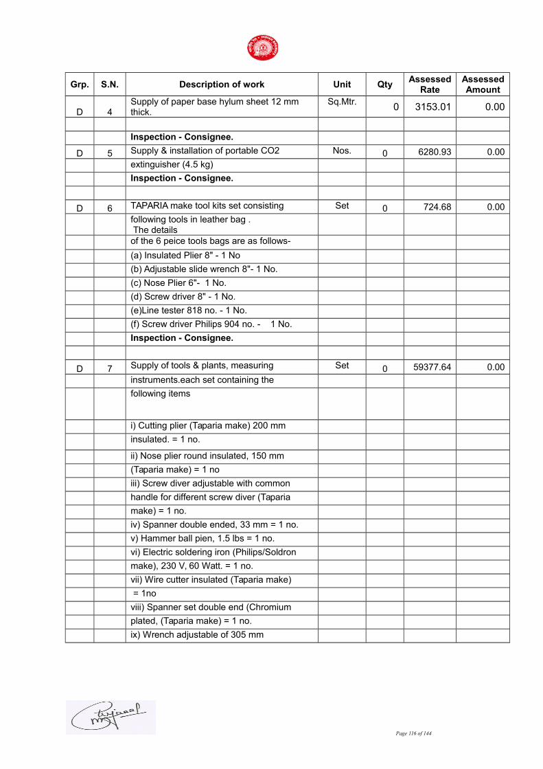
Grp. S.N. Description of work Unit QtyAssessed
RateAssessedAmount
D 4Supply of paper base hylum sheet 12 mm thick.
Sq.Mtr. 0 3153.01 0.00
Inspection - Consignee.
D 5 Supply & installation of portable CO2 Nos. 0 6280.93 0.00
extinguisher (4.5 kg)
Inspection - Consignee.
D 6 TAPARIA make tool kits set consisting Set 0 724.68 0.00
following tools in leather bag . The details
of the 6 peice tools bags are as follows-
(a) Insulated Plier 8" - 1 No
(b) Adjustable slide wrench 8"- 1 No.
(c) Nose Plier 6"- 1 No.
(d) Screw driver 8" - 1 No.
(e)Line tester 818 no. - 1 No.
(f) Screw driver Philips 904 no. - 1 No.
Inspection - Consignee.
D 7 Supply of tools & plants, measuring Set 0 59377.64 0.00
instruments.each set containing the
following items
i) Cutting plier (Taparia make) 200 mm
insulated. = 1 no.
ii) Nose plier round insulated, 150 mm
(Taparia make) = 1 no
iii) Screw diver adjustable with common
handle for different screw diver (Taparia
make) = 1 no.
iv) Spanner double ended, 33 mm = 1 no.
v) Hammer ball pien, 1.5 lbs = 1 no.
vi) Electric soldering iron (Philips/Soldron
make), 230 V, 60 Watt. = 1 no.
vii) Wire cutter insulated (Taparia make)
= 1no
viii) Spanner set double end (Chromium
plated, (Taparia make) = 1 no.
ix) Wrench adjustable of 305 mm
Page 116 of 144

Grp. S.N. Description of work Unit QtyAssessed
RateAssessedAmount
(Taparia make)=1 no.
x) Spanner double ended, 25 mm = 1 no.
xi) Megger, 0-500 volt (Motvani/Shanti
make)= 1 no
xii) Digital multimeter with following range
= 1 no.
a) 0-1000V AC/DC
b) 0-10 Amp
c) 0-1000 Ohms
3-1/2 digits
The meter shall be supplied with test
probes, leather cover battery and of
reputed make like Philips/Meco or similar.
xiii) Box spanner insulated 1/4 inch x 3/8
inch = 1 no.
xiv) Box spanner insulated 3/8 inch x 1/2
inch = 1 no.
xv) True RMS digital multimeter of 4 1/2
digits capable of measuring (i) 10 Amp AC
and DC current (ii) True RMS voltage with
a bandwidth of 5 Khz. Similar to Escorts 97
or Fluke.
xvi) Drill bits 7 mm - 7 nos.
Inspection - Consignee.
D 8 Supply of operation aids for station staff
a) Godrtej Chair model PCH-7002 or better Nos. 0 9533.53 0.00
b) Godrej Chair model KES - CH4 as supplied Nos. 0 1715.21 0.00
in ECR.
c) Godrej Office table model T-8 Nos. 0 6883.00 0.00
d) Godrej Slimline storewell Plain of size 1950 Nos. 0 9985.98 0.00
mm(H)x 507 mm (D) Approx with four
adjustable shelves.
Page 117 of 144
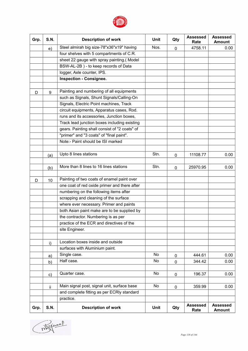
Grp. S.N. Description of work Unit QtyAssessed
RateAssessedAmount
e) Steel almirah big size-78"x36"x19" having Nos. 0 4758.11 0.00
four shelves with 5 compartments of C.R.
sheet 22 gauge with spray painting.( Model
BSW-AL-2B ) - to keep records of Data
logger, Axle counter, IPS.
Inspection - Consignee.
D 9 Painting and numbering of all equipments
such as Signals, Shunt Signals/Calling-On
Signals, Electric Point machines, Track
circuit equipments, Apparatus cases, Rod.
runs and its accessories, Junction boxes,
Track lead junction boxes including existing
gears. Painting shall consist of "2 coats" of
"primer" and "3 coats" of "final paint".
Note:- Paint should be ISI marked
(a) Upto 8 lines stations Stn. 0 11108.77 0.00
(b) More than 8 lines to 16 lines stations Stn. 0 25970.95 0.00
D 10 Painting of two coats of enamel paint over
one coat of red oxide primer and there after
numbering on the following items after
scrapping and cleaning of the surface
where ever necessary. Primer and paints
both Asian paint make are to be supplied by
the contractor. Numbering is as per
practice of the ECR and directives of the
site Engineer.
i) Location boxes inside and outside
surfaces with Aluminium paint.
a) Single case. No 0 444.61 0.00
b) Half case. No 0 344.42 0.00
c) Quarter case. No 0 196.37 0.00
ii Main signal post, signal unit, surface base No 0 359.99 0.00
and complete fitting as per ECRly standard
practice.
Grp. S.N. Description of work Unit QtyAssessed
RateAssessedAmount
Page 118 of 144
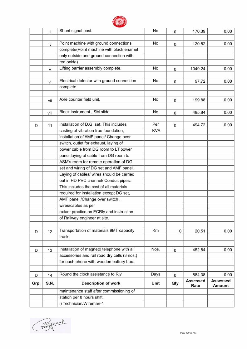
iii Shunt signal post. No 0 170.39 0.00
iv Point machine with ground connections No 0 120.52 0.00
complete(Point machine with black enamel
only outside and ground connection with
red oxide)
v Lifting barrier assembly complete. No 0 1049.24 0.00
vi Electrical detector with ground connection No 0 97.72 0.00
complete.
vii Axle counter field unit. No 0 199.88 0.00
viii Block instrument , SM slide No 0 495.84 0.00
D 11 Installation of D.G. set. This includes Per 0 494.72 0.00
casting of vibration free foundation, KVA
installation of AMF panel/ Change over
switch, outlet for exhaust, laying of
power cable from DG room to LT power
panel,laying of cable from DG room to
ASM's room for remote operation of DG
set and wiring of DG set and AMF panel.
Laying of cables/ wires should be carried
out in HD PVC channel/ Conduit pipes.
This includes the cost of all materials
required for installation except DG set,
AMF panel /Change over switch , wires/cables as per
extant practice on ECRly and instruction
of Railway engineer at site.
D 12 Transportation of materials 9MT capacity Km 0 20.51 0.00
truck
D 13 Installation of magneto telephone with all Nos. 0 452.84 0.00
accessories and rail road dry cells (3 nos.)
for each phone with wooden battery box.
D 14 Round the clock assistance to Rly Days 0 884.38 0.00
Grp. S.N. Description of work Unit QtyAssessed
RateAssessedAmount
maintenance staff after commissioning of
station per 8 hours shift.
i) Technician/Wireman-1
Page 119 of 144
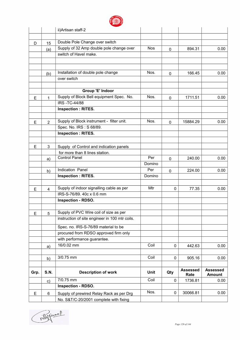
ii)Artisan staff-2
D 15 Double Pole Change over switch
(a) Supply of 32 Amp double pole change over Nos 0 894.31 0.00
switch of Havel make.
(b) Installation of double pole change Nos. 0 166.45 0.00
over switch
Group 'E' Indoor
E 1 Supply of Block Bell equipment Spec. No. Nos. 0 1711.51 0.00
IRS -TC-44/88
Inspection : RITES.
E 2 Supply of Block instrument - filter unit. Nos. 0 15884.29 0.00
Spec. No. IRS : S 68/89.
Inspection : RITES.
E 3 Supply of Control and indication panels
for more than 8 lines station.
a) Control Panel Per 0 240.00 0.00
Domino
b) Indication Panel Per 0 224.00 0.00
Inspection : RITES. Domino
E 4 Supply of indoor signalling cable as per Mtr 0 77.35 0.00
IRS-S-76/89. 40c x 0.6 mm
Inspection - RDSO.
E 5 Supply of PVC Wire coil of size as per
instruction of site engineer in 100 mtr coils.
Spec. no. IRS-S-76/89 material to be
procured from RDSO approved firm only
with performance guarantee.
a) 16/0.02 mm Coil 0 442.63 0.00
b) 3/0.75 mm Coil 0 905.16 0.00
Grp. S.N. Description of work Unit QtyAssessed
RateAssessedAmount
c) 7/0.75 mm Coil 0 1736.81 0.00
Inspection - RDSO.
E 6 Supply of prewired Relay Rack as per Drg Nos. 0 30066.81 0.00
No. S&T/C-20/2001 complete with fixing
Page 120 of 144
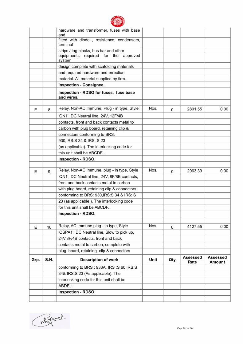
hardware and transformer, fuses with baseand
fitted with diode , resistence, condensers,terminal
strips / tag blocks, bus bar and other
equipments required for the approvedsystem
design complete with scafolding materials
and required hardware and errection
material. All material supplied by firm.
Inspection - Consignee.
Inspection - RDSO for fuses, fuse base and wires.
E 8 Relay, Non-AC Immune, Plug - in type, Style Nos. 0 2801.55 0.00
'QN1', DC Neutral line, 24V, 12F/4B
contacts, front and back contacts metal to
carbon with plug board, retaining clip &
connectors conforming to BRS:
930,IRS:S 34 & IRS: S 23
(as applicable). The interlocking code for
this unit shall be ABCDE.
Inspection - RDSO.
E 9 Relay, Non-AC Immune, plug - in type, Style Nos. 0 2963.39 0.00
'QN1', DC Neutral line, 24V, 8F/8B contacts,
front and back contacts metal to carbon
with plug board, retaining clip & connectors
conforming to BRS: 930,IRS:S 34 & IRS: S
23 (as applicable ). The interlocking code
for this unit shall be ABCDF.
Inspection - RDSO.
E 10 Relay, AC Immune plug - in type, Style Nos. 0 4127.55 0.00
'QSPA1', DC Neutral line, Slow to pick up,
24V,8F/4B contacts, front and back
contacts metal to carbon, complete with
plug board, retaining clip & connectors
Grp. S.N. Description of work Unit QtyAssessed
RateAssessedAmount
conforming to BRS : 933A, IRS :S 60,IRS:S
34& IRS:S 23 (As applicable). The
interlocking code for this unit shall be
ABDEJ.
Inspection - RDSO.
Page 121 of 144
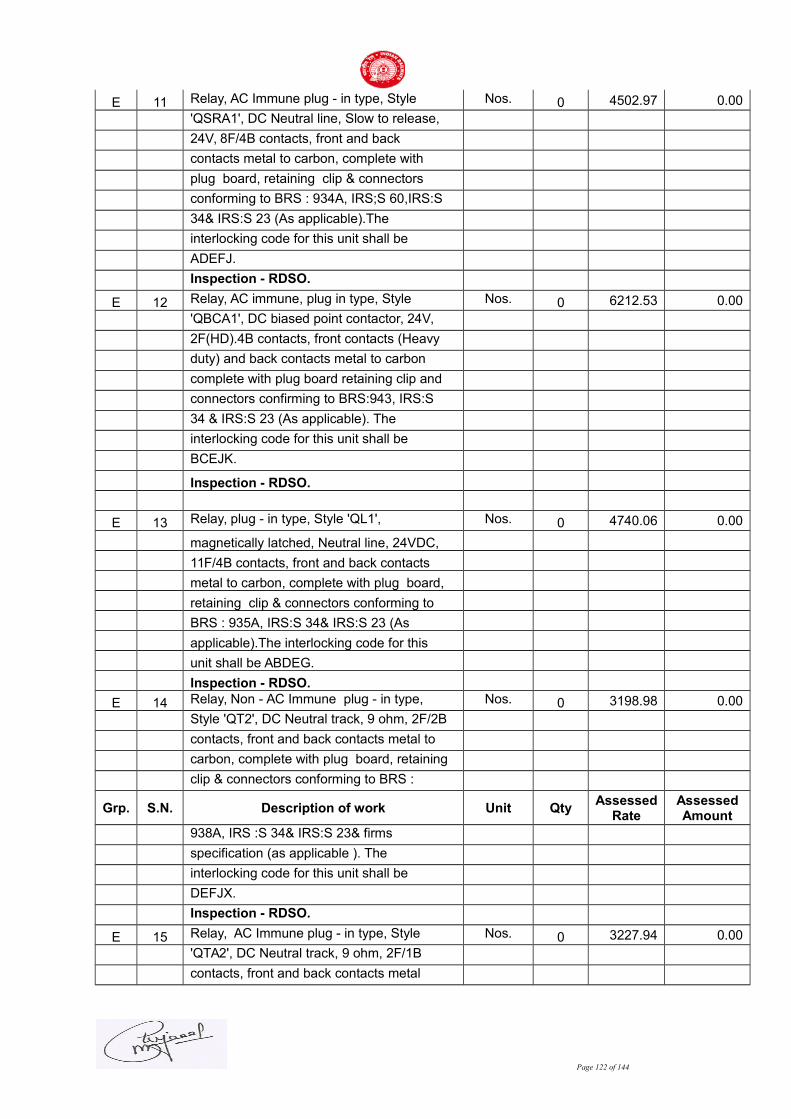
E 11 Relay, AC Immune plug - in type, Style Nos. 0 4502.97 0.00
'QSRA1', DC Neutral line, Slow to release,
24V, 8F/4B contacts, front and back
contacts metal to carbon, complete with
plug board, retaining clip & connectors
conforming to BRS : 934A, IRS;S 60,IRS:S
34& IRS:S 23 (As applicable).The
interlocking code for this unit shall be
ADEFJ.
Inspection - RDSO.
E 12 Relay, AC immune, plug in type, Style Nos. 0 6212.53 0.00
'QBCA1', DC biased point contactor, 24V,
2F(HD).4B contacts, front contacts (Heavy
duty) and back contacts metal to carbon
complete with plug board retaining clip and
connectors confirming to BRS:943, IRS:S
34 & IRS:S 23 (As applicable). The
interlocking code for this unit shall be
BCEJK.
Inspection - RDSO.
E 13 Relay, plug - in type, Style 'QL1', Nos. 0 4740.06 0.00
magnetically latched, Neutral line, 24VDC,
11F/4B contacts, front and back contacts
metal to carbon, complete with plug board,
retaining clip & connectors conforming to
BRS : 935A, IRS:S 34& IRS:S 23 (As
applicable).The interlocking code for this
unit shall be ABDEG.
Inspection - RDSO.
E 14 Relay, Non - AC Immune plug - in type, Nos. 0 3198.98 0.00
Style 'QT2', DC Neutral track, 9 ohm, 2F/2B
contacts, front and back contacts metal to
carbon, complete with plug board, retaining
clip & connectors conforming to BRS :
Grp. S.N. Description of work Unit QtyAssessed
RateAssessedAmount
938A, IRS :S 34& IRS:S 23& firms
specification (as applicable ). The
interlocking code for this unit shall be
DEFJX.
Inspection - RDSO.
E 15 Relay, AC Immune plug - in type, Style Nos. 0 3227.94 0.00
'QTA2', DC Neutral track, 9 ohm, 2F/1B
contacts, front and back contacts metal
Page 122 of 144
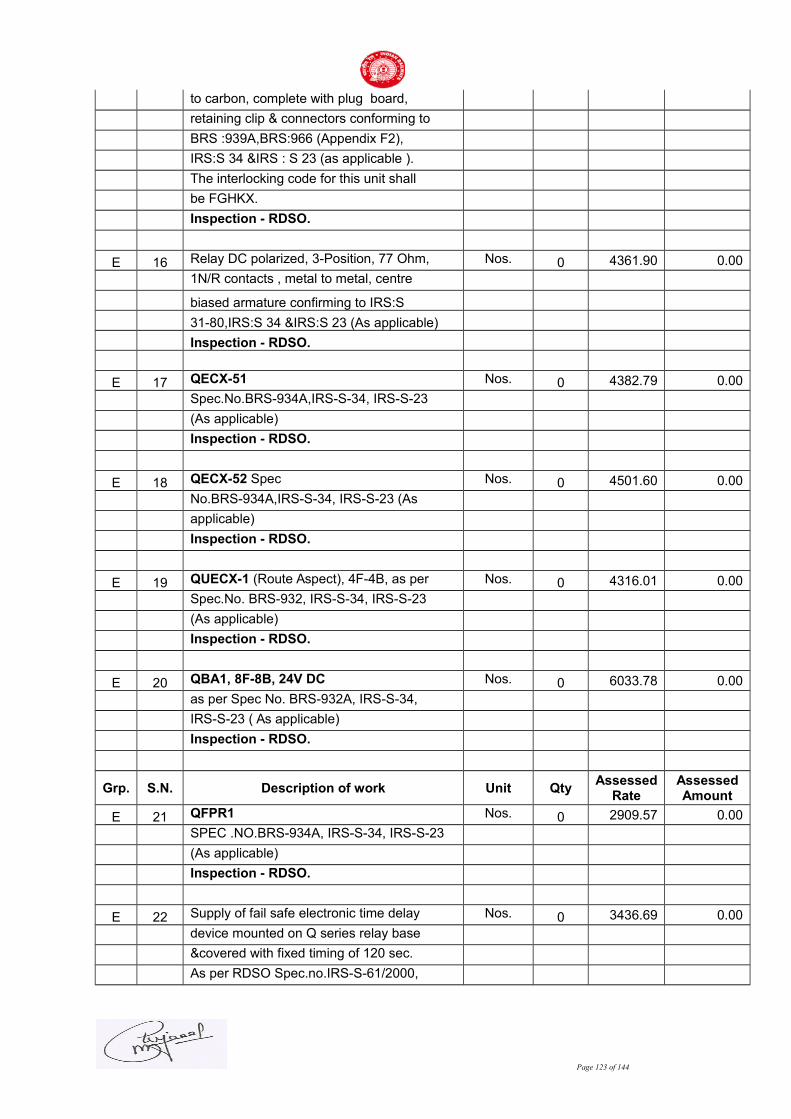
to carbon, complete with plug board,
retaining clip & connectors conforming to
BRS :939A,BRS:966 (Appendix F2),
IRS:S 34 &IRS : S 23 (as applicable ).
The interlocking code for this unit shall be FGHKX.
Inspection - RDSO.
E 16 Relay DC polarized, 3-Position, 77 Ohm, Nos. 0 4361.90 0.00
1N/R contacts , metal to metal, centre
biased armature confirming to IRS:S
31-80,IRS:S 34 &IRS:S 23 (As applicable)
Inspection - RDSO.
E 17 QECX-51 Nos. 0 4382.79 0.00
Spec.No.BRS-934A,IRS-S-34, IRS-S-23
(As applicable)
Inspection - RDSO.
E 18 QECX-52 Spec Nos. 0 4501.60 0.00
No.BRS-934A,IRS-S-34, IRS-S-23 (As
applicable)
Inspection - RDSO.
E 19 QUECX-1 (Route Aspect), 4F-4B, as per Nos. 0 4316.01 0.00
Spec.No. BRS-932, IRS-S-34, IRS-S-23
(As applicable)
Inspection - RDSO.
E 20 QBA1, 8F-8B, 24V DC Nos. 0 6033.78 0.00
as per Spec No. BRS-932A, IRS-S-34,
IRS-S-23 ( As applicable)
Inspection - RDSO.
Grp. S.N. Description of work Unit QtyAssessed
RateAssessedAmount
E 21 QFPR1 Nos. 0 2909.57 0.00
SPEC .NO.BRS-934A, IRS-S-34, IRS-S-23
(As applicable)
Inspection - RDSO.
E 22 Supply of fail safe electronic time delay Nos. 0 3436.69 0.00
device mounted on Q series relay base
&covered with fixed timing of 120 sec.
As per RDSO Spec.no.IRS-S-61/2000,
Page 123 of 144
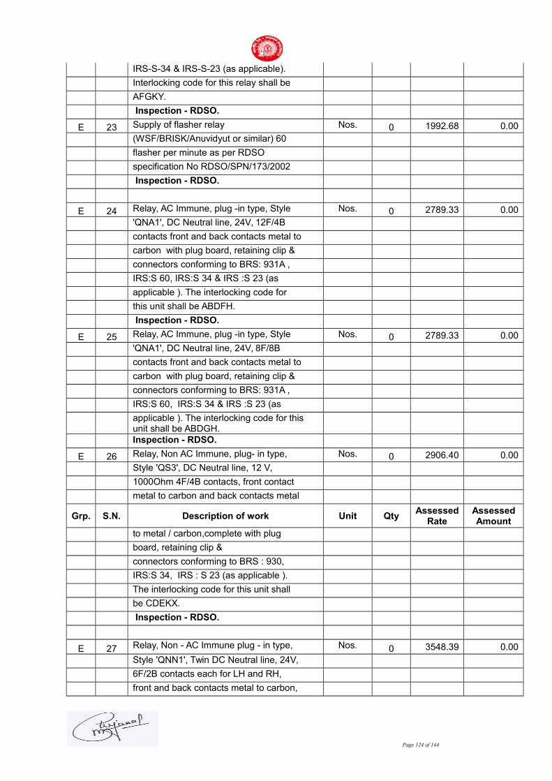
IRS-S-34 & IRS-S-23 (as applicable).
Interlocking code for this relay shall be
AFGKY.
Inspection - RDSO.
E 23 Supply of flasher relay Nos. 0 1992.68 0.00
(WSF/BRISK/Anuvidyut or similar) 60
flasher per minute as per RDSO
specification No RDSO/SPN/173/2002
Inspection - RDSO.
E 24 Relay, AC Immune, plug -in type, Style Nos. 0 2789.33 0.00
'QNA1', DC Neutral line, 24V, 12F/4B
contacts front and back contacts metal to
carbon with plug board, retaining clip &
connectors conforming to BRS: 931A ,
IRS:S 60, IRS:S 34 & IRS :S 23 (as
applicable ). The interlocking code for
this unit shall be ABDFH.
Inspection - RDSO.
E 25 Relay, AC Immune, plug -in type, Style Nos. 0 2789.33 0.00
'QNA1', DC Neutral line, 24V, 8F/8B
contacts front and back contacts metal to
carbon with plug board, retaining clip &
connectors conforming to BRS: 931A ,
IRS:S 60, IRS:S 34 & IRS :S 23 (as
applicable ). The interlocking code for this unit shall be ABDGH.
Inspection - RDSO.
E 26 Relay, Non AC Immune, plug- in type, Nos. 0 2906.40 0.00
Style 'QS3', DC Neutral line, 12 V,
1000Ohm 4F/4B contacts, front contact
metal to carbon and back contacts metal
Grp. S.N. Description of work Unit QtyAssessed
RateAssessedAmount
to metal / carbon,complete with plug board, retaining clip &
connectors conforming to BRS : 930,
IRS:S 34, IRS : S 23 (as applicable ).
The interlocking code for this unit shall
be CDEKX.
Inspection - RDSO.
E 27 Relay, Non - AC Immune plug - in type, Nos. 0 3548.39 0.00
Style 'QNN1', Twin DC Neutral line, 24V,
6F/2B contacts each for LH and RH,
front and back contacts metal to carbon,
Page 124 of 144
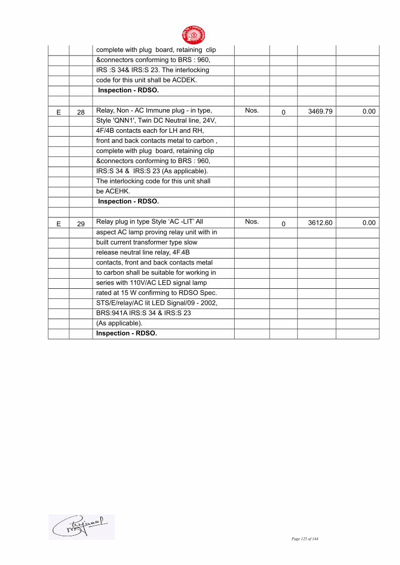
complete with plug board, retaining clip
&connectors conforming to BRS : 960,
IRS :S 34& IRS:S 23. The interlocking
code for this unit shall be ACDEK.
Inspection - RDSO.
E 28 Relay, Non - AC Immune plug - in type, Nos. 0 3469.79 0.00
Style 'QNN1', Twin DC Neutral line, 24V,
4F/4B contacts each for LH and RH,
front and back contacts metal to carbon ,
complete with plug board, retaining clip
&connectors conforming to BRS : 960,
IRS:S 34 & IRS:S 23 (As applicable).
The interlocking code for this unit shall
be ACEHK.
Inspection - RDSO.
E 29 Relay plug in type Style ‘AC -LIT’ All Nos. 0 3612.60 0.00
aspect AC lamp proving relay unit with in
built current transformer type slow
release neutral line relay, 4F.4B
contacts, front and back contacts metal
to carbon shall be suitable for working in series with 110V/AC LED signal lamp
rated at 15 W confirming to RDSO Spec.
STS/E/relay/AC lit LED Signal/09 - 2002,
BRS:941A IRS:S 34 & IRS:S 23
(As applicable).
Inspection - RDSO.
Page 125 of 144

Grp. S.N. Description of work Unit QtyAssessed
RateAssessedAmount
E 30 Relay AC immuned miniature plug in DC Nos. 0 3622.68 0.00
biased track tractive armature 2F/2B
contact ,9 Ohm . Front and back
contacts metal to carbon complete with
plug board retaining clips & connectors
QBAT relay.RDSO Spec No.
RDSO/SPN/84/88 Dt 16.5.91.
Inspection - RDSO.
E 31 Preparation of panel face diagram as per
spec.no.IRS-S-36-87 with modifications,
dt.05-7-94 of CSTE/E.Rly. Domino type
control Panel Spec no.:-
RDSO/SPN/186/2004 (Latest)
Note: After getting approval of the
above diagrams from railways, the
diagram is to be submitted in 6 sets of
ferro prints of the same. Out of this, 2 set to be submitted in
laminated plastic cover and in CD also.
i) Up to 4 Running lines stn. Stn. 0 8339.50 0.00
ii) Up to 8 Running lines stn. Stn. 0 11078.33 0.00
iii) Big yards having more than 8 Running Stn. 0 20108.00 0.00
to 16 lines stn.(Separate diagram for
lines Control and Indication Panels)
E 32 Installation, interconnection &
commissioning of block instrument along
with Block bell equipment, Block phone
etc as required in the station.
i) Single line Nos. 0 5600.00 0.00
ii) Double Line Nos. 0 6811.70 0.00
E 33 Installation wiring and commissioning of Nos. 0 1828.38 0.00
Block instrument filter unit . Spec. No.
IRS-TC-68/89.
Page 126 of 144

Grp. S.N. Description of work Unit QtyAssessed
RateAssessedAmount
E 34 Inter connection wiring with ladder
arrangement from power supply
equipment to relay rack, IPS, Data
logger, Control panel, Block instruments,
CTR etc. It also includes interconnection
wiring with ladder arrangement between
relay racks, CTR's,indication board and
block instruments. This also includes
termination of cables/ wires on all the
above and dressing, bunching etc. as
required at site. Wire shall be
16/0.02mm for relays, 3/0.737 mm for MCB's and 7/0.75 mm for power wiring.
Indoor cable 60x0.6mm/40x0.6mm as
per IRS-S-76/89 or Latest for
interconnection of indication board supplied by firm . Wires shall be
procured from RDSO approved firm and
inspected by RDSO. All Material will
supply by firm.
(i) Upto 4 lines stations Stn. 0 47236.56 0.00
(ii) Upto 8 lines stations Stn. 0 55668.64 0.00
(iii) Big yards having more than 8 lines upto 16 Stn. 0 101008.83 0.00
lines.
E 35 Carrying out alterations to the existing Per 0 209.00 0.00
relay wiring at relay rack / location as per Relay
the circuit diagram. The work includes
releasing the existing unused wires and
wiring the relays using wire PVC 16/0.02
mm copper. { Wire PVC 16/0.02 mm
copper,paint, soldering materials and all
other miscellaneous materials required
for the work shall be supplied by the contractor.)
Inspection - RDSO for PVC wire.
E 36 Design of detailed circuit and wiring Job 0 83000.00 0.00
diagram for Panel Interlocking on the basis
Grp. S.N. Description of work Unit QtyAssessed
RateAssessedAmount
Page 127 of 144

of approved signalling plan , control table
as per Rly latest practices including
contact analysis chart , relay disposition
chart,fuse analysis chart, relay register
with latest amendment including supply
of circuits and wiring diagram, design of
selection table.
(More than 8 lines to 18 lines station)
Note: Design and circuit to be submitted
in autocad and finally in CD in addition to
this diagram to be submitted in polyster
film tracing with 6 ferro copy of complete
drawing out of this two sets to be
submitted in laminated plastic cover.]
E 37 Preparation of Cable route plan , cable Job 0 88622.00 0.00
core chart, Power suppl;y layout, Cable
termination Chart in relay room and
location boxes, location wiring plan,
cable insulation chart, fuse analysis ,
equipment disposition plan ,track
bonding plan as per Rly practices. (More
than 8 lines to 18 lines station)
Note:- All diagram /Plan to be submitted
in auto cad and finally in CD in addition
to this diagrams/plan to be submitted in
two sets polyestor film tracing to the Rly
along with 6sets of Ferro prints of the above.
E 38 Installation of pre wired relay rack with Nos. 0 6438.79 0.00
scafolding materials ladder as per
drawing No. S&T/C/20/2001 fitted with
transformer,fuses, diode , resistance ,
condensers, terminal strips/ tag block, busbar and other component required
for approved system design complete
with scafolding materials
and required hardware and errection
materials to accomodate 100 relays
Note:- Alternate tag block terminals to be
used. Ferules to be provided. Fuse
Grp. S.N. Description of work Unit QtyAssessed
RateAssessedAmount
blown indication to be provided.
Page 128 of 144
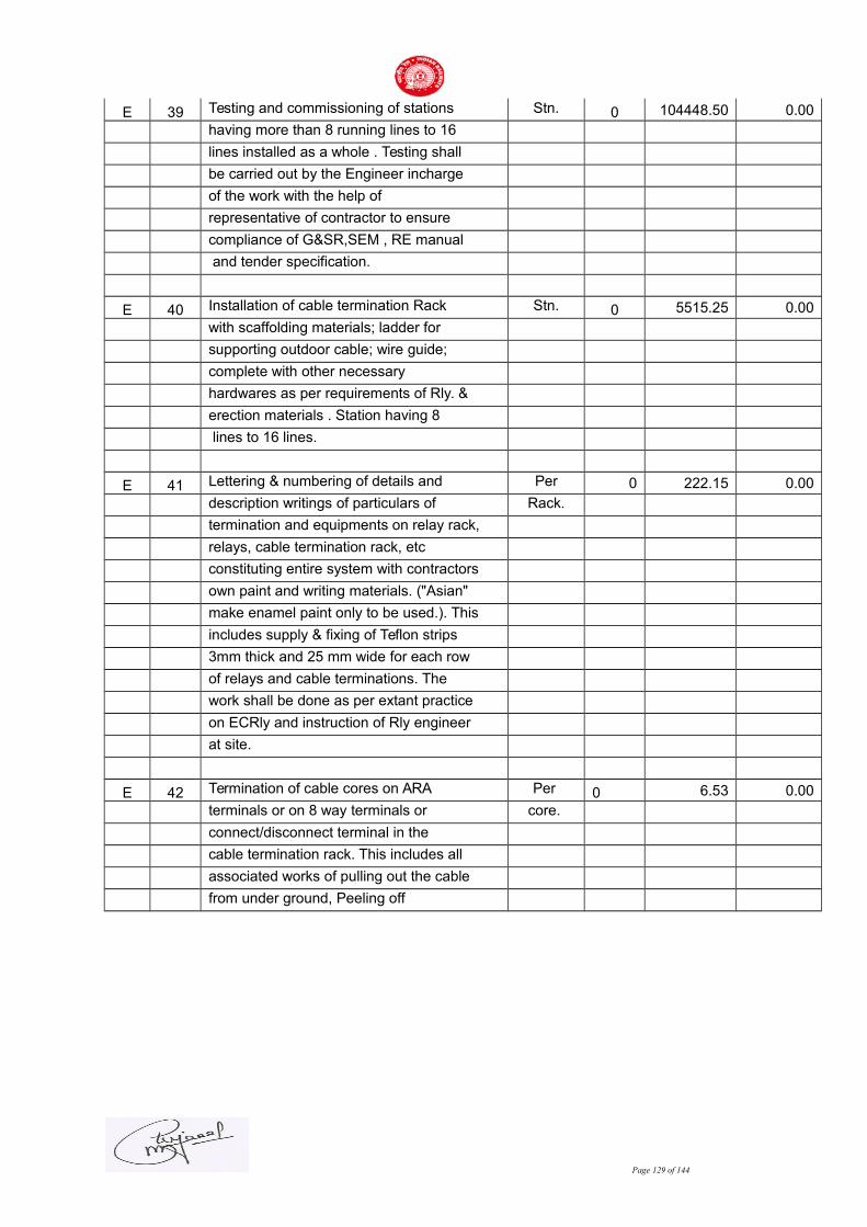
E 39 Testing and commissioning of stations Stn. 0 104448.50 0.00
having more than 8 running lines to 16
lines installed as a whole . Testing shall
be carried out by the Engineer incharge
of the work with the help of
representative of contractor to ensure
compliance of G&SR,SEM , RE manual
and tender specification.
E 40 Installation of cable termination Rack Stn. 0 5515.25 0.00
with scaffolding materials; ladder for
supporting outdoor cable; wire guide;
complete with other necessary
hardwares as per requirements of Rly. &
erection materials . Station having 8
lines to 16 lines.
E 41 Lettering & numbering of details and Per 0 222.15 0.00
description writings of particulars of Rack.
termination and equipments on relay rack,
relays, cable termination rack, etc
constituting entire system with contractors
own paint and writing materials. ("Asian"
make enamel paint only to be used.). This
includes supply & fixing of Teflon strips
3mm thick and 25 mm wide for each row
of relays and cable terminations. The
work shall be done as per extant practice
on ECRly and instruction of Rly engineer
at site.
E 42 Termination of cable cores on ARA Per 0 6.53 0.00
terminals or on 8 way terminals or core. connect/disconnect terminal in the
cable termination rack. This includes all
associated works of pulling out the cable
from under ground, Peeling off
Page 129 of 144

Grp. S.N. Description of work Unit QtyAssessed
RateAssessedAmount
insulation,dressing of cable core
supported on sting rod with contractors
own materials as per instruction of the
site incharge. The cable armour to be
earthed. Cable tags to be provided.
Group 'F' Siding Points
F 1 Supply of ARC lever, IRS Drg. No. Nos. 0 5807.25 0.00
SA-992/m.
Inspection-Consignee.
F 2 Supply of lock hand plunger (Complete Set 0 2874.24 0.00
with SS bar {BG}) Drg. No. SA 3279 A
(Adv) for 52 Kg. IRS :S 10/78 or latest.
Inspection-Consignee.
F 3 Assembling and installation of 4/2 way Nos. 0 43.31 0.00
trestle and fixing Strandard roller guide
by excavating and fixing the same in the
earth,rammed upto the top of the trestle
thus fixing the trestle assembly. Earth
work both in excavatin and filling about
300 mm on all sides around the trestle as required at site
to maintain the level of rodding run in
respect of rail level is also required to be
done. Bolts nuts split pins of proper size
are to be supplied by the contractors.
Supply of trestle, SRG, rollers and pins
is by railway.
F 4 Excavating ground and concreting Cum. 0 2437.23 0.00
foundation type A in cement, coarse
sand and aggregate (25 mm) in the ratio
of 1:3:6at different places. Cement
coarse sand and aggregate are to be
supplied by the contractor. The volume
of foundation shall be inclusive of the volume occupied by the
foundation type -A. Type A foundation
shall be given by Railway.
Grp. S.N. Description of work Unit QtyAssessed
RateAssessedAmount
Page 130 of 144
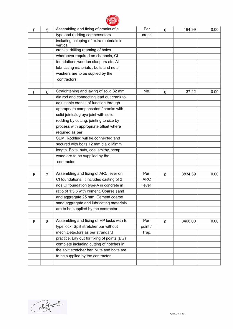
F 5 Assembling and fixing of cranks of all Per 0 194.99 0.00
type and rodding compensators crank
including chipping of extra materials in vertical
cranks, drilling reaming of holes
whereever required on channels, CI
foundations,wooden sleepers etc. All
lubricating materials , bolts and nuts,
washers are to be suplied by the
contractors
F 6 Straightening and laying of solid 32 mm Mtr. 0 37.22 0.00
dia rod and connecting lead out crank to
adjustable cranks of function through
appropriate compensators/ cranks with
solid joints/lug eye joint with solid
rodding by cutting, jointing to size by
process with appropriate offset where required as per
SEM. Rodding will be connected and
secured with bolts 12 mm dia x 65mm
length. Bolts, nuts, coal smithy, scrap
wood are to be supplied by the
contractor.
F 7 Assembling and fixing of ARC lever on Per 0 3834.39 0.00
CI foundations. It includes casting of 2 ARC
nos CI foundation type-A in concrete in lever
ratio of 1:3:6 with cement, Coarse sand
and aggregate 25 mm. Cement coarse
sand,aggregate and lubricating materials
are to be supplied by the contractor.
F 8 Assembling and fixing of HP locks with E Per 0 3466.00 0.00
type lock, Split stretcher bar without point /
mech.Detectors as per strandard Trap.
practice. Lay out for fixing of points (BG)
complete including cutting of notches in
the split stretcher bar. Nuts and bolts are
to be supplied by the contractor.
Page 131 of 144

Grp. S.N. Description of work Unit QtyAssessed
RateAssessedAmount
F 9 Connecting of point / trap to crank Per 0 1462.17 0.00
adjustable with 32 mm dia rodding, point point
adjusting screw as per plan including / Trap.
points adjusting also.Smithy process will
be used for forging the joints.
F 10 Assembling and installation of Points / Per 0 1949.57 0.00
trap indicator complete with lamp, target indicator
lense and mounting on its base. The
base will be concreted 450 mm x 500
mm in the ratio of 1:3:6 using cement , coarse sand and
aggreegate (25 mm).The indicators have
to work with points / trap by connecting
with extension piece of goose neck using
solid joint of 32 mm dia. Coarse sand,
cement,aggregate (25mm), bolts , nuts
and washer are to be supplied by the
contractor. Supply of point indicator
complete is by the Railways.
Group 'G' Signal
G 1 Supply of LED based signal unit for main
aspect as per RDSO specification
no.-RDSO/SPN/153/2002 or suitable for
110V AC supply can be used with
conventional as well as LED ECR along
with current regulator and health
monitoring unit.
(i) Red aspect. Nos. 0 13014.80 0.00
(ii) Yellow aspect Nos. 0 13014.80 0.00
(iii) Green aspect Nos. 0 14176.49 0.00
Inspection - RDSO.
Page 132 of 144
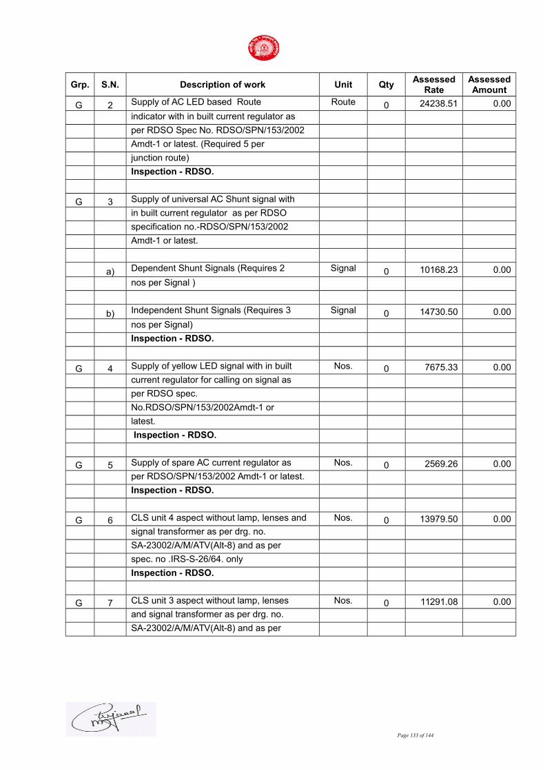
Grp. S.N. Description of work Unit QtyAssessed
RateAssessedAmount
G 2 Supply of AC LED based Route Route 0 24238.51 0.00
indicator with in built current regulator as
per RDSO Spec No. RDSO/SPN/153/2002
Amdt-1 or latest. (Required 5 per junction route)
Inspection - RDSO.
G 3 Supply of universal AC Shunt signal with
in built current regulator as per RDSO
specification no.-RDSO/SPN/153/2002
Amdt-1 or latest.
a) Dependent Shunt Signals (Requires 2 Signal 0 10168.23 0.00
nos per Signal )
b) Independent Shunt Signals (Requires 3 Signal 0 14730.50 0.00
nos per Signal)
Inspection - RDSO.
G 4 Supply of yellow LED signal with in built Nos. 0 7675.33 0.00
current regulator for calling on signal as
per RDSO spec.
No.RDSO/SPN/153/2002Amdt-1 or
latest.
Inspection - RDSO.
G 5 Supply of spare AC current regulator as Nos. 0 2569.26 0.00
per RDSO/SPN/153/2002 Amdt-1 or latest.
Inspection - RDSO.
G 6 CLS unit 4 aspect without lamp, lenses and Nos. 0 13979.50 0.00
signal transformer as per drg. no.
SA-23002/A/M/ATV(Alt-8) and as per
spec. no .IRS-S-26/64. only
Inspection - RDSO.
G 7 CLS unit 3 aspect without lamp, lenses Nos. 0 11291.08 0.00
and signal transformer as per drg. no.
SA-23002/A/M/ATV(Alt-8) and as per
Page 133 of 144
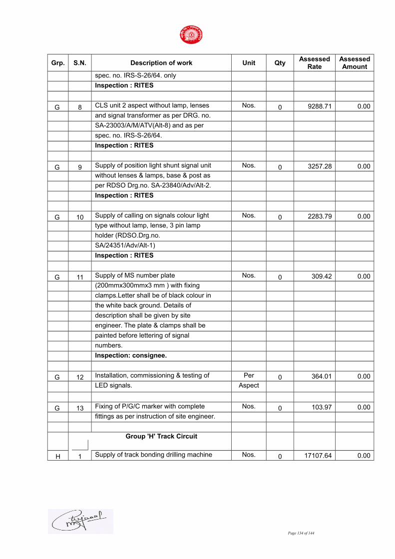
Grp. S.N. Description of work Unit QtyAssessed
RateAssessedAmount
spec. no. IRS-S-26/64. only
Inspection : RITES
G 8 CLS unit 2 aspect without lamp, lenses Nos. 0 9288.71 0.00and signal transformer as per DRG. no.
SA-23003/A/M/ATV(Alt-8) and as per
spec. no. IRS-S-26/64.
Inspection : RITES
G 9 Supply of position light shunt signal unit Nos. 0 3257.28 0.00
without lenses & lamps, base & post as
per RDSO Drg.no. SA-23840/Adv/Alt-2.
Inspection : RITES
G 10 Supply of calling on signals colour light Nos. 0 2283.79 0.00
type without lamp, lense, 3 pin lamp
holder (RDSO.Drg.no. SA/24351/Adv/Alt-1)
Inspection : RITES
G 11 Supply of MS number plate Nos. 0 309.42 0.00
(200mmx300mmx3 mm ) with fixing
clamps.Letter shall be of black colour in
the white back ground. Details of
description shall be given by site
engineer. The plate & clamps shall be
painted before lettering of signal numbers.
Inspection: consignee.
G 12 Installation, commissioning & testing of Per 0 364.01 0.00
LED signals. Aspect
G 13 Fixing of P/G/C marker with complete Nos. 0 103.97 0.00
fittings as per instruction of site engineer.
Group 'H' Track Circuit
H 1 Supply of track bonding drilling machine Nos. 0 17107.64 0.00
Page 134 of 144
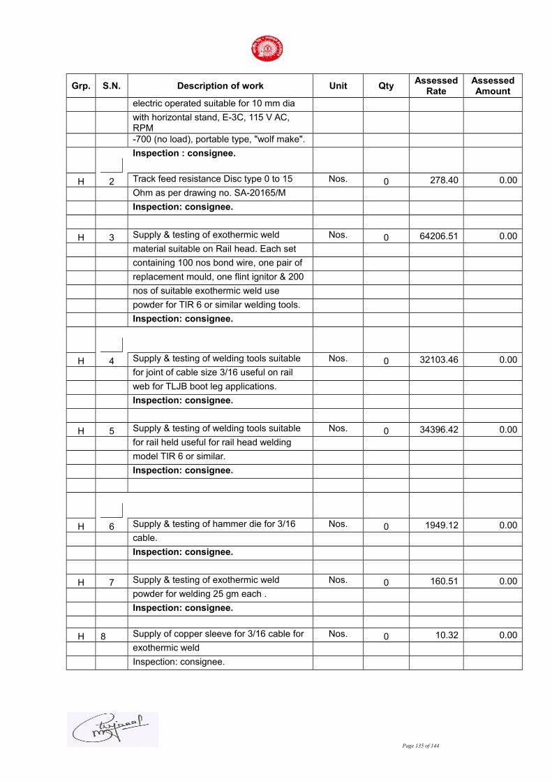
Grp. S.N. Description of work Unit QtyAssessed
RateAssessedAmount
electric operated suitable for 10 mm dia
with horizontal stand, E-3C, 115 V AC, RPM
-700 (no load), portable type, "wolf make".
Inspection : consignee.
H 2 Track feed resistance Disc type 0 to 15 Nos. 0 278.40 0.00
Ohm as per drawing no. SA-20165/M
Inspection: consignee.
H 3 Supply & testing of exothermic weld Nos. 0 64206.51 0.00
material suitable on Rail head. Each set
containing 100 nos bond wire, one pair of
replacement mould, one flint ignitor & 200
nos of suitable exothermic weld use
powder for TIR 6 or similar welding tools.
Inspection: consignee.
H 4 Supply & testing of welding tools suitable Nos. 0 32103.46 0.00
for joint of cable size 3/16 useful on rail
web for TLJB boot leg applications.
Inspection: consignee.
H 5 Supply & testing of welding tools suitable Nos. 0 34396.42 0.00
for rail held useful for rail head welding
model TIR 6 or similar.
Inspection: consignee.
H 6 Supply & testing of hammer die for 3/16 Nos. 0 1949.12 0.00
cable.
Inspection: consignee.
H 7 Supply & testing of exothermic weld Nos. 0 160.51 0.00
powder for welding 25 gm each .
Inspection: consignee.
H 8 Supply of copper sleeve for 3/16 cable for Nos. 0 10.32 0.00
exothermic weld
Inspection: consignee.
Page 135 of 144
Grp. S.N. Description of work Unit QtyAssessed
RateAssessedAmount
Page 136 of 144

H 9 Supply & testing of graphite mould for Nos. 0 10318.99 0.00
replacing suitable joints of cable size 3/16
on rail web for bootleg application mould. It
should be in pit LH & RH.
Inspection: consignee.
H 10 Supply of heavy duty grinder mechine with Nos. 0 15880.91 0.00
battery.
Inspection: consignee.
H 11 Supply & fixing of bonds of 3/16 " , 6-1/2" Nos. 0 561.81 0.00
of XS style No. IRSBS 24882 or similar in of
boxes. Each box containing 100 nos of bonds
bonds of 3/16" dia of XS style No.IRSBS
24882 or similar along with one pair of
replacement moulds, fire ignitor and
necessry weld metal.
Inspection: consignee.
H 12 Welding of joint of cable size 3/16" useful Per 0 19.50 0.00
on rail web for TLJB / Boot leg application weld.
by exothermic weld bonding method. All
consumable materials shall be supplied by
Railway.
Group 'I'
Dismantling & releasing
I 1Releasing of lever frame, Point mechanism ,
Stn.0
13367.46 0.00
detectors, Power supply equipments in
locations /Cabins/SM's room etc and other
ground gears inluding indicators ,
abandoned signal posts etc.
I 2 Releasing of signals and location boxes , Stn. 0 11725.04 0.00
other ground gears.
I 3Transportation of released materials except
Stn.0
18227.35 0.00
Rail posts, over head alignment to Store of
SSE/Works and stacking properly as per
instruction of site Engineer.
Grp. S.N. Description of work Unit QtyAssessed
RateAssessedAmount
I 4 Dismantling & Releasing of following S&T
gears. The work includes transportation of
the released material to the store of
Page 137 of 144
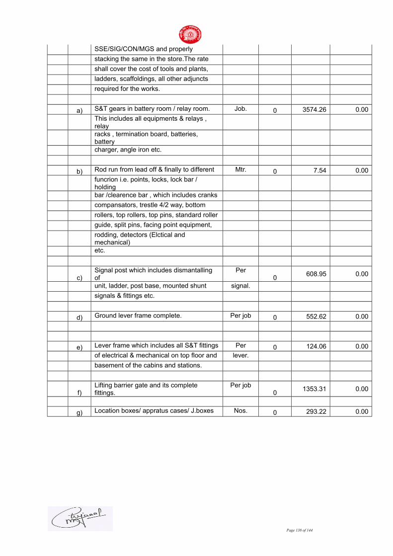
SSE/SIG/CON/MGS and properly
stacking the same in the store.The rate
shall cover the cost of tools and plants,
ladders, scaffoldings, all other adjuncts
required for the works.
a) S&T gears in battery room / relay room. Job. 0 3574.26 0.00
This includes all equipments & relays , relay
racks , termination board, batteries, battery
charger, angle iron etc.
b) Rod run from lead off & finally to different Mtr. 0 7.54 0.00
funcrion i.e. points, locks, lock bar / holding
bar /clearence bar , which includes cranks
compansators, trestle 4/2 way, bottom
rollers, top rollers, top pins, standard roller
guide, split pins, facing point equipment,
rodding, detectors (Elctical and mechanical)
etc.
c)Signal post which includes dismantalling of
Per0
608.95 0.00
unit, ladder, post base, mounted shunt signal.
signals & fittings etc.
d) Ground lever frame complete. Per job 0 552.62 0.00
e) Lever frame which includes all S&T fittings Per 0 124.06 0.00
of electrical & mechanical on top floor and lever.
basement of the cabins and stations.
f)Lifting barrier gate and its complete fittings.
Per job0
1353.31 0.00
g) Location boxes/ appratus cases/ J.boxes Nos. 0 293.22 0.00
Page 138 of 144
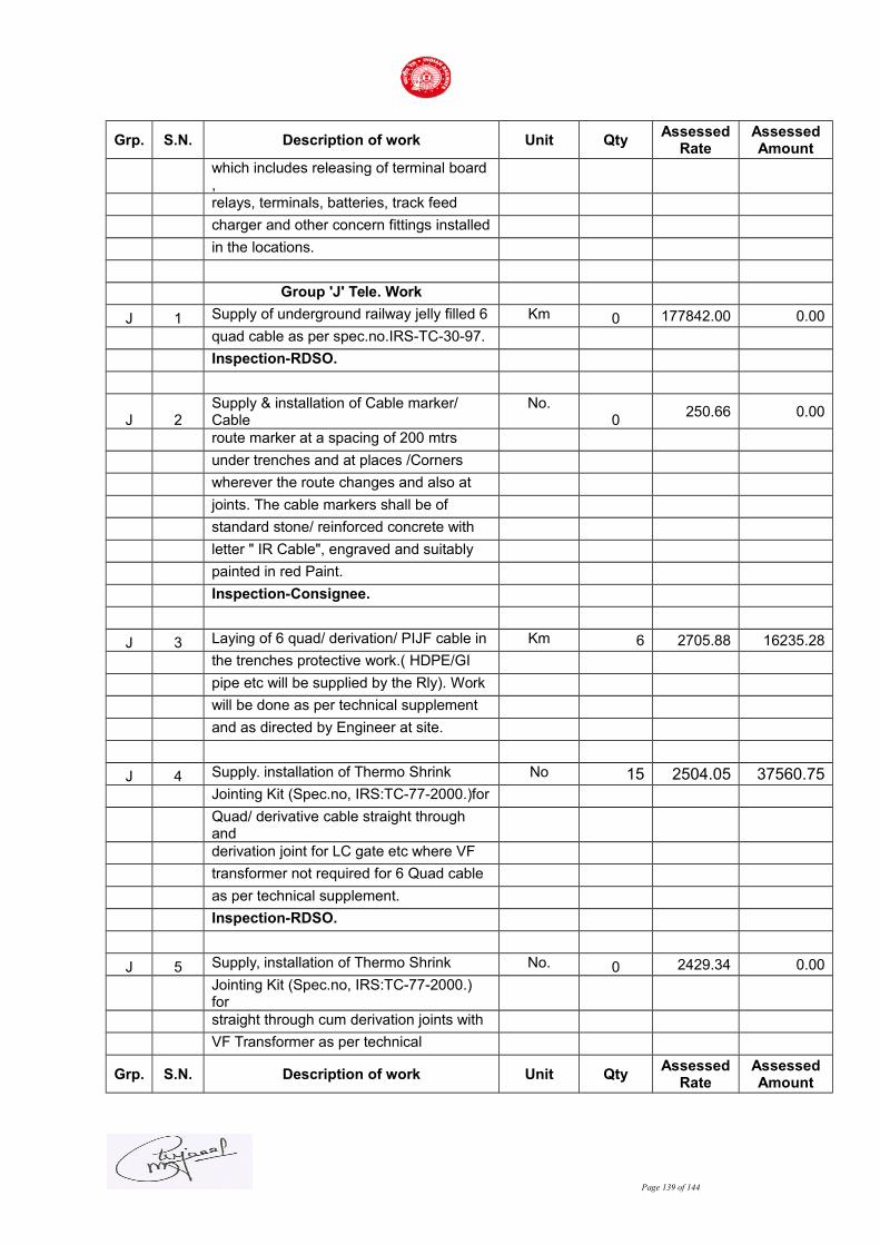
Grp. S.N. Description of work Unit QtyAssessed
RateAssessedAmount
which includes releasing of terminal board,
relays, terminals, batteries, track feed
charger and other concern fittings installed
in the locations.
Group 'J' Tele. Work
J 1 Supply of underground railway jelly filled 6 Km 0 177842.00 0.00
quad cable as per spec.no.IRS-TC-30-97.
Inspection-RDSO.
J 2Supply & installation of Cable marker/ Cable
No.0
250.66 0.00
route marker at a spacing of 200 mtrs
under trenches and at places /Corners
wherever the route changes and also at
joints. The cable markers shall be of
standard stone/ reinforced concrete with
letter " IR Cable", engraved and suitably
painted in red Paint.
Inspection-Consignee.
J 3 Laying of 6 quad/ derivation/ PIJF cable in Km 6 2705.88 16235.28
the trenches protective work.( HDPE/GI
pipe etc will be supplied by the Rly). Work
will be done as per technical supplement
and as directed by Engineer at site.
J 4 Supply. installation of Thermo Shrink No 15 2504.05 37560.75
Jointing Kit (Spec.no, IRS:TC-77-2000.)for
Quad/ derivative cable straight through and
derivation joint for LC gate etc where VF
transformer not required for 6 Quad cable
as per technical supplement.
Inspection-RDSO.
J 5 Supply, installation of Thermo Shrink No. 0 2429.34 0.00
Jointing Kit (Spec.no, IRS:TC-77-2000.) for
straight through cum derivation joints with
VF Transformer as per technical
Grp. S.N. Description of work Unit QtyAssessed
RateAssessedAmount
Page 139 of 144
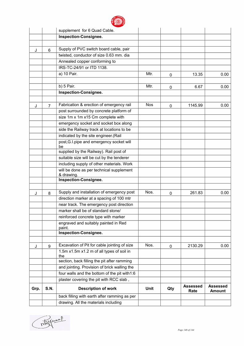
supplement for 6 Quad Cable.
Inspection-Consignee.
J 6 Supply of PVC switch board cable, pair
twisted, conductor of size 0.63 mm. dia
Annealed copper conforming to
IRS-TC-24/91 or ITD 1138.
a) 10 Pair. Mtr. 0 13.35 0.00
b) 5 Pair. Mtr. 0 6.67 0.00
Inspection-Consignee.
J 7 Fabrication & erection of emergency rail Nos 0 1145.99 0.00
post surrounded by concrete platform of
size 1m x 1m x15 Cm complete with
emergency socket and socket box along
side the Railway track at locations to be
indicated by the site engineer.(Rail
post,G.I.pipe and emergency socket will be
supplied by the Railway). Rail post of
suitable size will be cut by the tenderer
including supply of other materials. Work
will be done as per technical supplement & drawing.
Inspection-Consignee.
J 8 Supply and installation of emergency post Nos. 0 261.83 0.00
direction marker at a spacing of 100 mtr
near track. The emergency post direction
marker shall be of standard stone/
reinforced concrete type with marker
engraved and suitably painted in Red paint.
Inspection-Consignee.
J 9 Excavation of Pit for cable jointing of size Nos. 0 2130.29 0.00
1.5m x1.5m x1.2 m of all types of soil in the
section, back filling the pit after ramming
and jointing. Provision of brick walling the
four walls and the bottom of the pit with1:6
plaster covering the pit with RCC slab ,
Grp. S.N. Description of work Unit QtyAssessed
RateAssessedAmount
back filling with earth after ramming as per drawing. All the materials including
Page 140 of 144
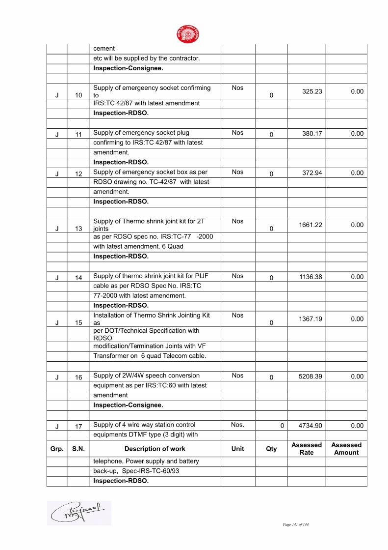
cement
etc will be supplied by the contractor.
Inspection-Consignee.
J 10Supply of emergeency socket confirming to
Nos0
325.23 0.00
IRS:TC 42/87 with latest amendment
Inspection-RDSO.
J 11 Supply of emergency socket plug Nos 0 380.17 0.00
confirming to IRS:TC 42/87 with latest
amendment.
Inspection-RDSO.
J 12 Supply of emergency socket box as per Nos 0 372.94 0.00
RDSO drawing no. TC-42/87 with latest
amendment.
Inspection-RDSO.
J 13Supply of Thermo shrink joint kit for 2T joints
Nos0
1661.22 0.00
as per RDSO spec no. IRS:TC-77 -2000
with latest amendment. 6 Quad
Inspection-RDSO.
J 14 Supply of thermo shrink joint kit for PIJF Nos 0 1136.38 0.00
cable as per RDSO Spec No. IRS:TC
77-2000 with latest amendment.
Inspection-RDSO.
J 15Installation of Thermo Shrink Jointing Kit as
Nos0
1367.19 0.00
per DOT/Technical Specification with RDSO
modification/Termination Joints with VF
Transformer on 6 quad Telecom cable.
J 16 Supply of 2W/4W speech conversion Nos 0 5208.39 0.00
equipment as per IRS:TC:60 with latest
amendment
Inspection-Consignee.
J 17 Supply of 4 wire way station control Nos. 0 4734.90 0.00
equipments DTMF type (3 digit) with
Grp. S.N. Description of work Unit QtyAssessed
RateAssessedAmount
telephone, Power supply and battery
back-up, Spec-IRS-TC-60/93
Inspection-RDSO.
Page 141 of 144
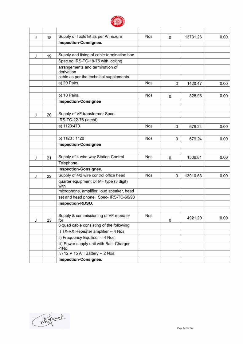
J 18 Supply of Tools kit as per Annexure Nos 0 13731.26 0.00
Inspection-Consignee.
J 19 Supply and fixing of cable termination box.
Spec.no.IRS-TC-18-75 with locking
arrangements and termination of derivation
cable as per the technical supplements.
a) 20 Pairs Nos 0 1420.47 0.00
b) 10 Pairs. Nos 0 828.96 0.00
Inspection-Consignee
J 20 Supply of VF transformer Spec.
IRS-TC-22-76 (latest)
a) 1120:470 Nos 0 679.24 0.00
b) 1120 : 1120 Nos 0 679.24 0.00
Inspection-Consignee
J 21 Supply of 4 wire way Station Control Nos 0 1506.81 0.00
Telephone.
Inspection-Consignee.
J 22 Supply of 4/2 wire control office head Nos 0 13910.63 0.00
quarter equipment DTMF type (3 digit) with
microphone, amplifier, loud speaker, head
set and head phone. Spec- IRS-TC-60/93
Inspection-RDSO.
J 23Supply & commissioning of VF repeater for
Nos0
4921.20 0.00
6 quad cable consisting of the following:
I) TX-RX Repeater amplifier -- 4 Nos
ii) Frequency Equiliser -- 4 Nos.
iii) Power supply unit with Batt. Charger -1No.
iv) 12 V 15 AH Battery -- 2 Nos.
Inspection-Consignee.
Page 142 of 144
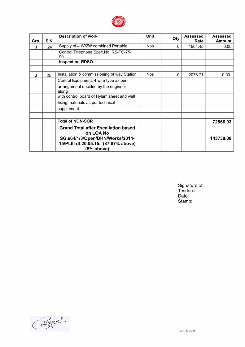
Grp. S.N.Description of work Unit
QtyAssessed
RateAssessed
Amount
J 24 Supply of 4 W/2W combined Portable Nos 0 1504.45 0.00
Control Telephone Spec.No.IRS-TC-75-99.
Inspection-RDSO.
J 25 Installation & commissioning of way Station Nos 0 2076.71 0.00
Control Equipment, 4 wire type as per
arrangement decided by the engineer along
with control board of Hylum sheet and wall
fixing materials as per technical
supplement.
Total of NON-SOR 72866.03
Grand Total after Escallation basedon LOA No
SG.664/1/3/Open/DHN/Works/2014-15/Pt.III dt.20.05.15. (87.87% above)
(5% above)
143738.08
Signature of TendererDate:Stamp:
Page 143 of 144
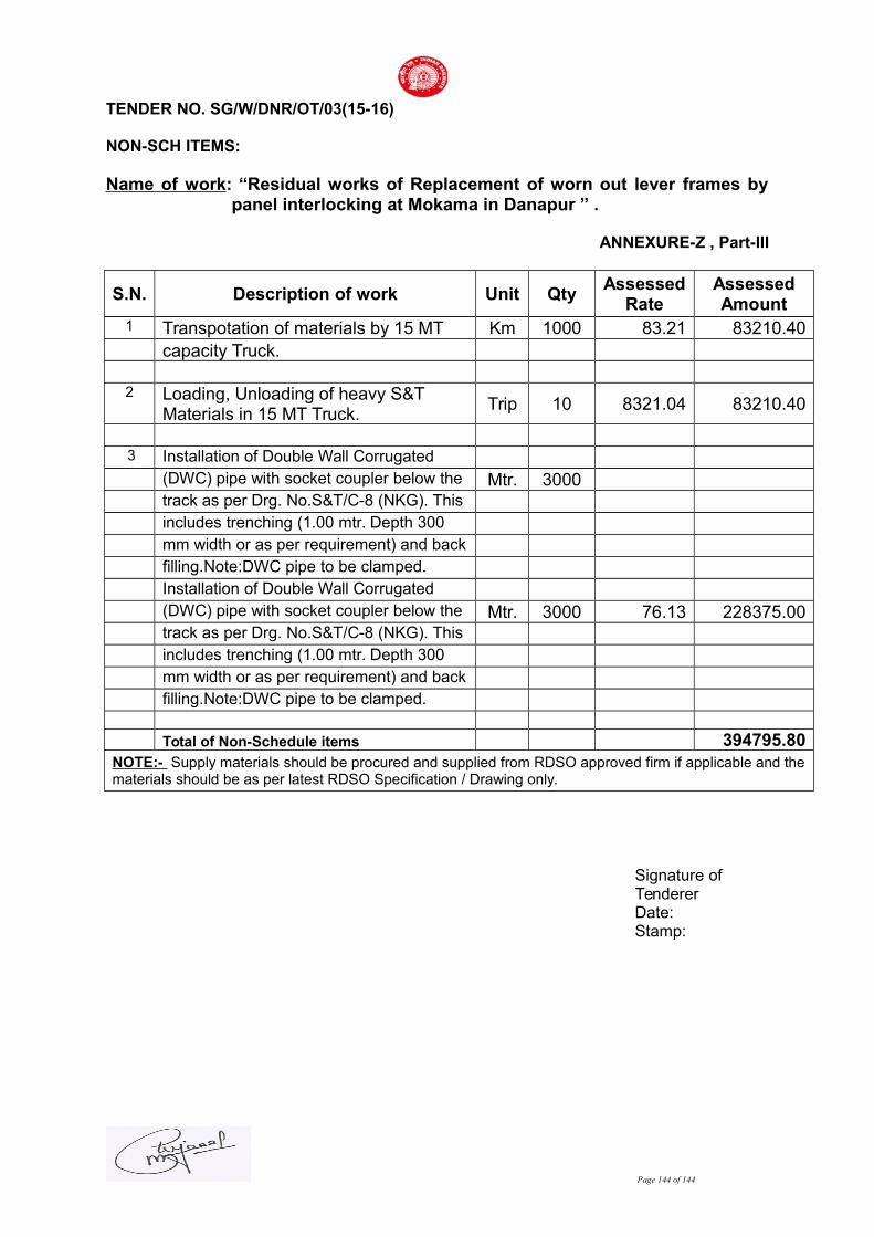
TENDER NO. SG/W/DNR/OT/03(15-16)
NON-SCH ITEMS:
Name of work: “Residual works of Replacement of worn out lever frames bypanel interlocking at Mokama in Danapur ” .
ANNEXURE-Z , Part-III
S.N. Description of work Unit QtyAssessed
RateAssessedAmount
1 Transpotation of materials by 15 MT Km 1000 83.21 83210.40 capacity Truck.
2 Loading, Unloading of heavy S&T Materials in 15 MT Truck.
Trip 10 8321.04 83210.40
3 Installation of Double Wall Corrugated (DWC) pipe with socket coupler below the Mtr. 3000 track as per Drg. No.S&T/C-8 (NKG). This includes trenching (1.00 mtr. Depth 300 mm width or as per requirement) and back filling.Note:DWC pipe to be clamped. Installation of Double Wall Corrugated (DWC) pipe with socket coupler below the Mtr. 3000 76.13 228375.00 track as per Drg. No.S&T/C-8 (NKG). This includes trenching (1.00 mtr. Depth 300 mm width or as per requirement) and back filling.Note:DWC pipe to be clamped.
Total of Non-Schedule items 394795.80NOTE:- Supply materials should be procured and supplied from RDSO approved firm if applicable and thematerials should be as per latest RDSO Specification / Drawing only.
Signature of TendererDate:Stamp:
Page 144 of 144


![[START OF TENDER DOCUMENT] TENDER NOTICE NO.ZRTI/SINI ... · TENDER NOTICE NO.ZRTI/SINI ... AT THE ZONAL RAILWAY TRAINING INSTITUTE, SINI ZRTI,Sini is located near SINI Railway](https://img.pdfslide.net/doc/110x75/5af8306d7f8b9a9e5991b113/start-of-tender-document-tender-notice-nozrtisini-notice-nozrtisini-.jpg)