Embed Size (px)
Citation preview

Inverter User Manual
EDS1000: 0.4-55kW
Shenzhen Gozuk Co., Limited
Motor control & drives manufacturer Website: www.gozuk.com
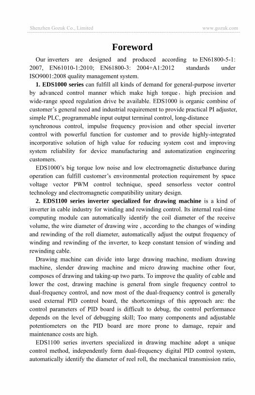
Foreword Our inverters are designed and produced according to EN61800-5-1:
2007, EN61010-1:2010; EN61800-3: 2004+A1:2012 standards under ISO9001:2008 quality management system.
1. EDS1000 series can fulfill all kinds of demand for general-purpose inverter by advanced control manner which make high torque high precision and wide-range speed regulation drive be available. EDS1000 is organic combine of customer’s general need and industrial requirement to provide practical PI adjuster, simple PLC, programmable input output terminal control, long-distance synchronous control, impulse frequency provision and other special inverter control with powerful function for customer and to provide highly-integrated incorporative solution of high value for reducing system cost and improving system reliability for device manufacturing and automatization engineering customers.
EDS1000’s big torque low noise and low electromagnetic disturbance during operation can fulfill customer’s environmental protection requirement by space voltage vector PWM control technique, speed sensorless vector control technology and electromagnetic compatibility unitary design.
2. EDS1100 series inverter specialized for drawing machine is a kind of inverter in cable industry for winding and rewinding control. Its internal real-time computing module can automatically identify the coil diameter of the receive volume, the wire diameter of drawing wire , according to the changes of winding and rewinding of the roll diameter, automatically adjust the output frequency of winding and rewinding of the inverter, to keep constant tension of winding and rewinding cable.
Drawing machine can divide into large drawing machine, medium drawing machine, slender drawing machine and micro drawing machine other four, composes of drawing and taking-up two parts. To improve the quality of cable and lower the cost, drawing machine is general from single frequency control to dual-frequency control, and now most of the dual-frequency control is generally used external PID control board, the shortcomings of this approach are: the control parameters of PID board is difficult to debug, the control performance depends on the level of debugging skill; Too many components and adjustable potentiometers on the PID board are more prone to damage, repair and maintenance costs are high.
EDS1100 series inverters specialized in drawing machine adopt a unique control method, independently form dual-frequency digital PID control system, automatically identify the diameter of reel roll, the mechanical transmission ratio,
Shenzhen Gozuk Co., Limited www.gozuk.com--------------------------------------------------------------------------------------------------------------------------
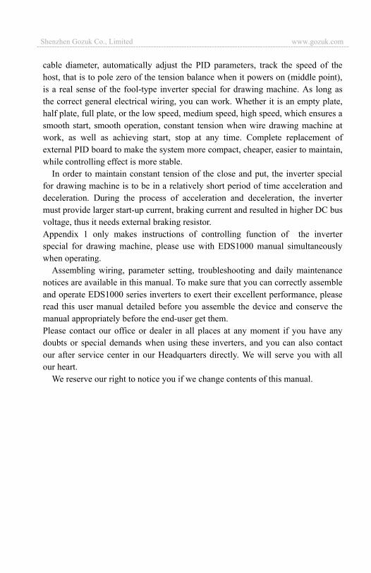
cable diameter, automatically adjust the PID parameters, track the speed of the host, that is to pole zero of the tension balance when it powers on (middle point), is a real sense of the fool-type inverter special for drawing machine. As long as the correct general electrical wiring, you can work. Whether it is an empty plate, half plate, full plate, or the low speed, medium speed, high speed, which ensures a smooth start, smooth operation, constant tension when wire drawing machine at work, as well as achieving start, stop at any time. Complete replacement of external PID board to make the system more compact, cheaper, easier to maintain, while controlling effect is more stable.
In order to maintain constant tension of the close and put, the inverter special for drawing machine is to be in a relatively short period of time acceleration and deceleration. During the process of acceleration and deceleration, the inverter must provide larger start-up current, braking current and resulted in higher DC bus voltage, thus it needs external braking resistor. Appendix 1 only makes instructions of controlling function of the inverter special for drawing machine, please use with EDS1000 manual simultaneously when operating.
Assembling wiring, parameter setting, troubleshooting and daily maintenance notices are available in this manual. To make sure that you can correctly assemble and operate EDS1000 series inverters to exert their excellent performance, please read this user manual detailed before you assemble the device and conserve the manual appropriately before the end-user get them. Please contact our office or dealer in all places at any moment if you have any doubts or special demands when using these inverters, and you can also contact our after service center in our Headquarters directly. We will serve you with all our heart.
We reserve our right to notice you if we change contents of this manual.
Shenzhen Gozuk Co., Limited www.gozuk.com---------------------------------------------------------------------------------------------------------------------------
CONTENTS 1 Safety information and use notice points
1.1 Safety precautions
1.2 Use range
1.3 Use notice points
1.4 Scrap notice points
2 Type and specification of the inverter 2.1 Incoming inverter inspect
2.2 Type explanation
2.3 Series type explanation
2.4 Appearance and parts name explanation
2.5 Outer size and gross weight
2.6 Outer size of key board and its fixing box
2.7 Product technic index and spec
3 Installation and wiring 3.1 Installation ambient
3.1.1 Demand for installation ambient
3.1.2 Installation direction and space
3.2 Parts disassembly and installation
3.2.1 Key board disassembly and installation
3.2.2 Plastic/metal cover disassembly and installation
3.3 Wiring notice points
3.4 Main loop terminal wiring
3.4.1 Connection between inverter and fitting parts
3.4.2 Main loop terminal wiring
3.5 Basic running wiring diagram
3.6 Control loop collocation and wiring
3.6.1 Location&function of terminal and slide switch
3.6.2 Explanation for control panel terminal
3.6.3 Analog input output terminal wiring
3.6.4 Communication terminal wiring
3.7 Installation guide for anti-jamming
3.7.1 Restraining to noise disturbance
3.7.2 Locale wiring and earthing
3.7.3 Relation of long-distance wiring and current leak
and the countermeasure
3.7.4 Installation demand for electromagnetic on-off
electronic device
4 Run and operation explanation for inverter 4.1 Run of inverter
4.1.1 Running order channels
4.1.2 Frequency-provision channel
4.1.3 Work state
4.1.4 Run mode
4.2 Operation and use of key board
4.2.1 Keypad layout
4.2.2 Keypad function description
4.2.3 LED and indicator light
4.2.4 Key board display status
4.2.5 Method for operating keypad
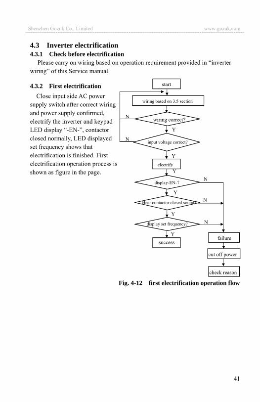
4.3 Inverter electrification
4.3.1 Check before electrification
4.3.2 First electrification
5 Function parameter schedule graph 5.1 Symbol description
5.2 Function parameter schedule graph
6 Detailed function description 6.1 Basic run function parameter group: F0
6.2 Start, stop, braking function parameter group:F1
6.3 Auxiliary run function parameter group: F2
6.4 Closed-loop run function parameter group: F3
6.5 Simple PLC function parameter group:F4
6.6 Terminal correlative function parameter group: F5
6.7 Traverse special function parameter group: F6
6.8 Frequency provision function parameter group: F7
6.9 Motor and vector control parameter group: F8
6.10 Protection function parameter group:F9
6.11 Failure record function parameter group: Fd
6.12 Password and manufacturer function parameter group: FF
6.13 Stop assistant function parameter group: FA
7 Troubleshooting 7.1 Failure and countermeasure
7.2 Failure record lookup
7.3 Failure reset
8 Maintenance 8.1 Routine maintenance
8.2 Inspection and replacement of damageable parts
8.3 Repair guarantee
8.4 Storage
9 Fitting parts 9.1 Communication subassembly
9.1.1 Long-distance operation key board
9.1.2 Communication cable
10 Examples10.1 Common speed regulation running
10.2 Terminal control running
10.3 Multi-step speed control running
10.4 Closed-loop control system
10.5 Consecutive action running
10.6 Application to constant pressure water supply
118119120121

11 Serial port RS485 communication protocol Appendix1 EDS1100 drawing machine inverter manual Appendix2 The manual of EDS1300 middle frequency inverter
Appendix3 Modus communication protocol(need customized special process)
Appendix4 Braking resistance
127136155
169177
1
1 Safety information and use notice points In order to ensure the safety of your personal and equipment, before using the
inverter, please read this chapter of contents conscientiously. 1.1 Safety precautions
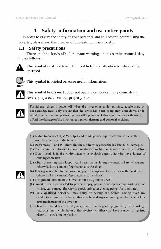
There are three kinds of safe relevant warnings in this service manual, they are as follows:
This symbol explains items that need to be paid attention to when being operated. This symbol is briefed on some useful information. This symbol briefs on: If does not operate on request, may cause death, severely injured or serious property loss.
note
!
!
(1) Forbid to connect U, V, W output end to AC power supply, otherwise cause the complete damage of the inverter.
(2) Don't make P- and P + short-circuited, otherwise cause the inverter to be damaged. (3) The inverter is forbidden to install on the flammables, otherwise have danger of fire. (4) Don't install it in the environment with explosive gas, otherwise have danger of
causing explosion. (5) After connecting main loop, should carry on insulating treatment to bare wiring end,
otherwise have danger of getting an electric shock. (6) If being connected to the power supply, don't operate the inverter with moist hands,
otherwise have danger of getting an electric shock. (7) The ground terminal of the inverter must be grounded well. (8) Inverter being connected to power supply, please don't open cover and carry on
wiring, can connect the wire or check only after closing power for10 minutes. (9) Only qualified personnel may carry on wiring and forbid leaving over any
conductive thing in machine, otherwise have danger of getting an electric shock or causing damage of the inverter.
(10) Inverter stored for over 2 years, should be stepped up gradually with voltage regulator first while having the electricity, otherwise have danger of getting electric shock and explosion.
!
Forbid user directly power off when the inverter is under running, accelerating or decelerating, must only ensure that the drive has been completely shut down or in standby situation can perform power off operation. Otherwise, the users themselves afford the damage of the inverter, equipment damage and personal accident.
!
Shenzhen Gozuk Co., Limited www.gozuk.com---------------------------------------------------------------------------------------------------------------------------
2
1.2 Use range (1) This inverter is only suitable for three phases AC asynchronous motor in
general industrial field. (2) While applying inverter to such equipments that relate much to the life, great
property, safety devices etc., must handle cautiously, and consult with producer, please.
(3) This inverter belongs to the control device of general industrial motor, if used in dangerous equipment, must consider the security safeguard procedures when the inverter breaks down.
1.3 Use notice points (1) EDS1000 series inverter is voltage-type inverter, so temperature, noise and
vibration slightly increasing compared to power source running when using, belongs to normal phenomenon.
(2) If need to run for a long time with constant torque of low-speed, must select motor of frequency conversion for use. Use general asynchronous AC motor when running at a low speed, should control temperature of the motor or carry on heat dissipation measure forcedly, so as not to burn the generator.
(3) Such mechanical device needing lubricating as the gearbox and gear wheel, etc., after running at a low speed for a long time, may be damaged as lubrication result become poor, please take necessary measure in advance.
(4) When the motor running with frequency above specified, besides considering the vibration, noise increase of the motor, must also confirm speed range of the motor bearing and the mechanical device.
(5) For hoist and great inertia load, etc., the inverter would shut off frequently due to over-current or over-voltage failure, in order to guarantee normal work, should consider choosing proper brake package.
(6) Should switch on/off the inverter through terminal or other normal order channels. It is prohibited that switch on/off the inverter frequently by using strong electric switch such as magnetic control conductor, otherwise will cause the equipment to be damaged.
(7) If need to install such switch as the magnetic control conductor, etc. between
(1) It is prohibited that connect AC 220V signal to control ends except TA, TB, TC, otherwise have danger of damaging property.
(2) If the inverter is damaged or without all parts, please don't install and operate it, otherwise have danger of fire or cause personnel to be injured.
(3) When installing, should choose a place where can endure the inverter, otherwise have danger of injuring personnel or damaging property while falling down.
!
Shenzhen Gozuk Co., Limited www.gozuk.com---------------------------------------------------------------------------------------------------------------------------

3
inverter output and the motor, please guarantee the inverter is switched on/off without output, otherwise may damage the inverter.
(8) The inverter may meet with mechanical resonance of the load within certain range of frequency output, can set up jumping frequency to evade.
(9) Before using, should confirm the voltage of the power is within the working voltage range allowed, otherwise should vary voltage or order special inverter.
(10) In the condition of altitude above 1000 meters, should use the inverter in lower volume, reduce output current by 10% of specified current after each 1500 meters height increasing.
(11) Should make insulation check to the motor before using it for the first time or after a long time placement. Please inspect with 500V voltage-type megohm meter according to method shown as graph 1-1 and insulation resistance should not be smaller than 5 M , otherwise inverter may be damaged.
(12) To forbid assembling capacitor for improving power factor or lightningproof voltage-sensible resistance etc., otherwise will cause malfunction trip of the inverter or damage of the parts, shown as graph 1-2.
Fig.1-1 motor insulation measure Fig.1-2 capacitor at output side forbidden
1.4 Scrap notice points When disposing scrap inverter and its parts, please note: (1) The unit: please discard as industrial useless. (2) Electrolytic capacitor: when burning the inverter electrolytic capacitor
in it may explode. (3) Plastic: when plastic, rubber parts etc. in the inverter are burning, they
may bring bad, poisonous gas, so please be ready to safeguards.
EDS2000U VW
M EDS1000
EDS1000
motor
Grounding part
Megohm meter
After wiring, short-circuit U, V, W to measure insulation resistance.
U V W
Shenzhen Gozuk Co., Limited www.gozuk.com---------------------------------------------------------------------------------------------------------------------------
4
2 Type and specification of the inverter 2.1 Incoming inverter inspect (1) Check if there is damage during transportation and inverter itself has damage
or fall-off parts. (2) Check if parts presented in packing list are all ready. (3) Please confirm rated data of the inverter is in line with your order requirement.
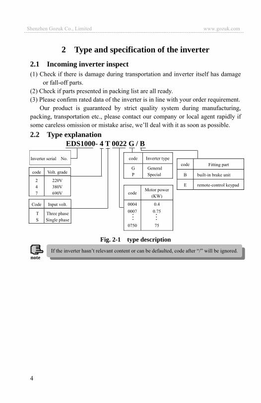
Our product is guaranteed by strict quality system during manufacturing, packing, transportation etc., please contact our company or local agent rapidly if some careless omission or mistake arise, we’ll deal with it as soon as possible. 2.2 Type explanation
Fig. 2-1 type description
Inverter serial No.
EDS1000- 4 T 0022 G / B
Code Input volt.
TS
Three phase Single phase
code Volt. grade
247
220V 380V 690V
code Inverter type
GP
GeneralSpecial
code Fitting part
B built-in brake unit
E remote-control keypad
codeMotor power
(KW)
00040007
0750
0.40.75
75
noteIf the inverter hasn’t relevant content or can be defaulted, code after “/” will be ignored.
Shenzhen Gozuk Co., Limited www.gozuk.com---------------------------------------------------------------------------------------------------------------------------
5
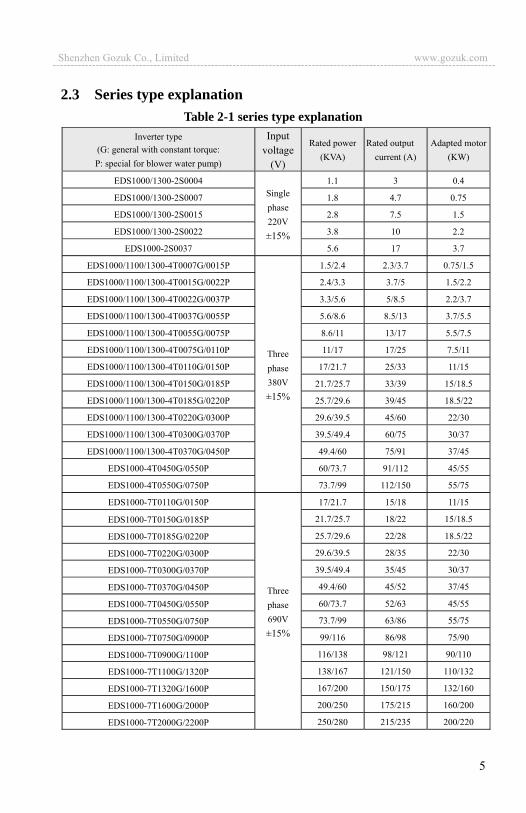
2.3 Series type explanation Table 2-1 series type explanation
Inverter type (G: general with constant torque: P: special for blower water pump)
Input voltage
(V)
Rated power(KVA)
Rated output current (A)
Adapted motor(KW)
EDS1000/1300-2S0004 Singlephase220V ±15%
1.1 3 0.4
EDS1000/1300-2S0007 1.8 4.7 0.75
EDS1000/1300-2S0015 2.8 7.5 1.5
EDS1000/1300-2S0022 3.8 10 2.2
EDS1000-2S0037 5.6 17 3.7
EDS1000/1100/1300-4T0007G/0015P
Threephase380V ±15%
1.5/2.4 2.3/3.7 0.75/1.5
EDS1000/1100/1300-4T0015G/0022P 2.4/3.3 3.7/5 1.5/2.2
EDS1000/1100/1300-4T0022G/0037P 3.3/5.6 5/8.5 2.2/3.7
EDS1000/1100/1300-4T0037G/0055P 5.6/8.6 8.5/13 3.7/5.5
EDS1000/1100/1300-4T0055G/0075P 8.6/11 13/17 5.5/7.5
EDS1000/1100/1300-4T0075G/0110P 11/17 17/25 7.5/11
EDS1000/1100/1300-4T0110G/0150P 17/21.7 25/33 11/15
EDS1000/1100/1300-4T0150G/0185P 21.7/25.7 33/39 15/18.5
EDS1000/1100/1300-4T0185G/0220P 25.7/29.6 39/45 18.5/22
EDS1000/1100/1300-4T0220G/0300P 29.6/39.5 45/60 22/30
EDS1000/1100/1300-4T0300G/0370P 39.5/49.4 60/75 30/37
EDS1000/1100/1300-4T0370G/0450P 49.4/60 75/91 37/45
EDS1000-4T0450G/0550P 60/73.7 91/112 45/55
EDS1000-4T0550G/0750P 73.7/99 112/150 55/75
EDS1000-7T0110G/0150P
Threephase690V ±15%
17/21.7 15/18 11/15
EDS1000-7T0150G/0185P 21.7/25.7 18/22 15/18.5
EDS1000-7T0185G/0220P 25.7/29.6 22/28 18.5/22
EDS1000-7T0220G/0300P 29.6/39.5 28/35 22/30
EDS1000-7T0300G/0370P 39.5/49.4 35/45 30/37
EDS1000-7T0370G/0450P 49.4/60 45/52 37/45
EDS1000-7T0450G/0550P 60/73.7 52/63 45/55
EDS1000-7T0550G/0750P 73.7/99 63/86 55/75
EDS1000-7T0750G/0900P 99/116 86/98 75/90
EDS1000-7T0900G/1100P 116/138 98/121 90/110
EDS1000-7T1100G/1320P 138/167 121/150 110/132
EDS1000-7T1320G/1600P 167/200 150/175 132/160
EDS1000-7T1600G/2000P 200/250 175/215 160/200
EDS1000-7T2000G/2200P 250/280 215/235 200/220
Shenzhen Gozuk Co., Limited www.gozuk.com---------------------------------------------------------------------------------------------------------------------------
6
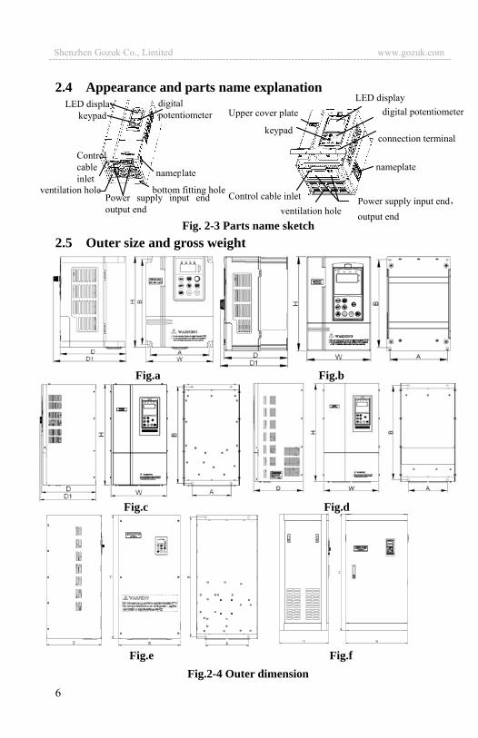
2.4 Appearance and parts name explanation
Fig. 2-3 Parts name sketch 2.5 Outer size and gross weight
Fig.a Fig.b
Fig.c Fig.d
Fig.e Fig.f Fig.2-4 Outer dimension
D W
ventilation hole
nameplate
LED display digital potentiometer
Control cable inlet
keypad
bottom fitting holePower supply input end output end
digital potentiometer
Power supply input endoutput end
nameplate
connection terminal
LED display
Control cable inlet
Upper cover plate
keypad
ventilation hole
Shenzhen Gozuk Co., Limited www.gozuk.com---------------------------------------------------------------------------------------------------------------------------

7
Table 2-2 EDS1000-2S0004~EDS1000-4T0750P mounting size
Inverter type (G: general; P: special)
Fixingapertu
re G.W. Fig.
EDS1000/1300-2S0004 EDS1000/1300-2S0007
110 160 125 170 123.2 135.5 4 2 Fig a
EDS1000/1300-2S0015 EDS1000/1300-2S0022
EDS1000/EDS1100/1300-4T0007G/0015P
EDS1000/EDS1100/1300-4T0015G/0022P
EDS1000/1100/1300-4T0022G/0037P
EDS1000-2S0037
140 215 155 230 155 164 5 3.8 Fig bEDS1000/1100/1300-4T0037G/0055P
EDS1000/1100/1300-4T0055G/0075P
EDS1000/1100/1300-4T0075G/0110P 185 275 200 290 178 187 6 6.3 Fig b
EDS1000/1100/1300-4T0110G/0150P
EDS1000/1100/1300-4T0150G/0185P 135 330 218 345 210 221 7 10 Fig c
EDS1000/1100/1300-4T0185G/0220P 180 410 260 430 252 261 9 17 Fig c
EDS1000/1100/1300-4T0220G/0300P
EDS1000/1100/1300-4T0300G/0370P 200 485 280 505 252 261 9 23 Fig c
EDS1000/1100/1300-4T0370G/0450P
EDS1000-4T0450G/0550P 200 515 300 535 252 261 9 33 Fig c
EDS1000-4T0550G/0750P 250 620 370 645 258 267 12 52 Fig c
Table 2-2 EDS1000-7T0110G~EDS1000-7T1320G mounting size
Inverter type Fixing
aperture Fig.
EDS1000-7T0110G/0150P 200 552 284 570 252.7 9 Fig e
EDS1000-7T0150G/0185P
EDS1000-7T0185G/0220P
280 620 420 650 300 9 Fig dEDS1000-7T0220G/0300P
EDS1000-7T0300G/0370P
EDS1000-7T0370G/0450P
EDS1000-7T0450G/0550P 320 720 500 750 300 12 Fig d
EDS1000-7T0550G/0750P
EDS1000-7T0750G/0900P
400 790 590 820 372 12 Fig dEDS1000-7T0900G/1100P
EDS1000-7T1100G/1320P
EDS1000-7T1320G/1600P
EDS1000-7T1600G/2000P - - 630 1200 500 - Fig f
EDS1000-7T2000G/2200P
Shenzhen Gozuk Co., Limited www.gozuk.com---------------------------------------------------------------------------------------------------------------------------

8
2.6 Outer size of keypad and its fixing box (unit: mm)
Fig.2-5 EN-KB5 outer size Fig.2-5 EN-KB5 hole size
Fig.2-7 EN-KB6 outer size Fig.2-8 EN-KB6 hole size
2.7 Product technic index and spec
Item Item description
Input
Rating volt., frequency 3 phase 690V grade, 3 phase 690V ,50Hz/60Hz; 3 phase 380V grade, 3 phase 380V ,50Hz/60Hz; 1 phase 220V grade, 1 phase 220V ,50Hz/60Hz
Allowed work volt. range 3 phase 690 V grade: 586V~760V3 phase 380 V grade: 320V~460V1 phase 220V grade: 200V~260V
output Voltage
690V grade: 0~690V; 380V grade: 0~380V; 220V grade: 0~220V
Frequency 0Hz-400Hz
Shenzhen Gozuk Co., Limited www.gozuk.com---------------------------------------------------------------------------------------------------------------------------
9
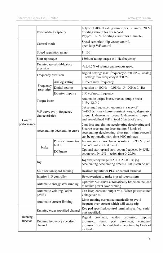
Over loading capacity G type: 150% of rating current for1 minute 200% of rating current for 0.5 secondP type: 120% of rating current for 1 minute
Control performance
Control mode Speed sensorless slip vector control, open loop V/F control
Speed regulation range 1: 100
Start-up torque 150% of rating torque at 1 Hz frequency
Running speed stable state precision 0.5% of rating synchronous speed
Frequency precision Digital setting: max. frequency 0.01% analog setting: max.frequency 0.5%
Frequency resolution
Analog setting 0.1% of max. frequency
Digital setting precision : <100Hz 0.01Hz; 100Hz: 0.1Hz
Exterior impulse 0.5% of max. frequency
Torque boost Automatic torque boost, manual torque boost 0.1%~12.0%
V/F curve (volt. frequency characteristic)
Set rating frequency randomly at range of 5~400Hz can choose constant torque, degressive torque 1, degressive torque 2, degressive torque 3 and user-defined V/F in total 5 kinds of curve
Accelerating decelerating curve
2 modes: straight line accelerating decelerating andS curve accelerating decelerating; 7 kinds of accelerating decelerating time (unit minute/second can be optioned), max. time 6000 minutes.
brake
Power consumption brake
Interior or exterior brake resistance. 690 V grade haven’t build-in brake unit .
DC brake Optional start-up and stop action frequency 0~15Hzaction volt. 0~15% action time 0~20.0 s
Jog Jog frequency range: 0.50Hz~50.00Hz; jog accelerating decelerating time 0.1~60.0s can be set
Multisection speed running Realized by interior PLC or control terminal
Interior PID controller Be convenient to make closed-loop system
Automatic energy save running Optimize V/F curve automatically based on the load to realize power save running
Automatic volt. regulation (AVR)
Can keep constant output volt. When power source voltage varies.
Automatic current limiting Limit running current automatically to avoid frequent over-current which will cause trip
Running function
Running order specified channel Key pad specified, control terminal specified, serialport specified.
Running frequency specified channel
Digital provision, analog provision, impulse provision, serial port provision, combined provision can be switched at any time by kinds of method.
Shenzhen Gozuk Co., Limited www.gozuk.com---------------------------------------------------------------------------------------------------------------------------
10
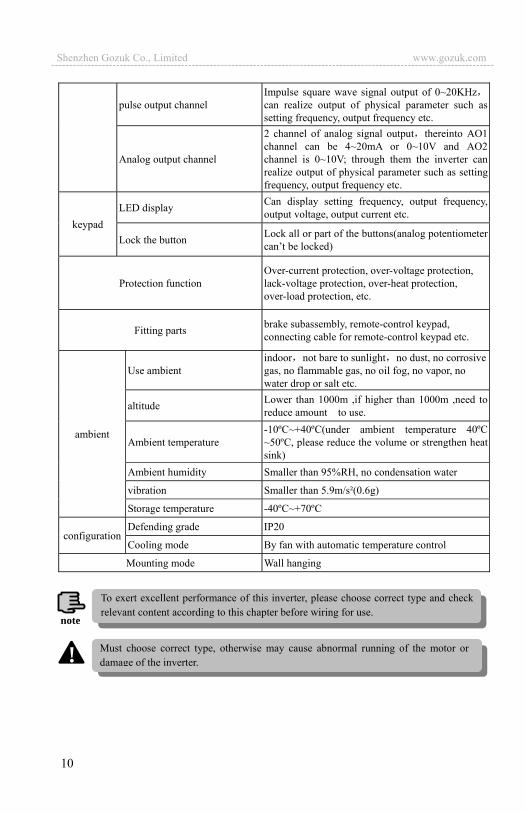
pulse output channel Impulse square wave signal output of 0~20KHzcan realize output of physical parameter such as setting frequency, output frequency etc.
Analog output channel
2 channel of analog signal output thereinto AO1 channel can be 4~20mA or 0~10V and AO2 channel is 0~10V; through them the inverter can realize output of physical parameter such as setting frequency, output frequency etc.
keypad LED display Can display setting frequency, output frequency,
output voltage, output current etc.
Lock the button Lock all or part of the buttons(analog potentiometer can’t be locked)
Protection function Over-current protection, over-voltage protection, lack-voltage protection, over-heat protection, over-load protection, etc.
Fitting parts brake subassembly, remote-control keypad, connecting cable for remote-control keypad etc.
ambient
Use ambient indoor not bare to sunlight no dust, no corrosivegas, no flammable gas, no oil fog, no vapor, no water drop or salt etc.
altitude Lower than 1000m ,if higher than 1000m ,need to reduce amount to use.
Ambient temperature -10ºC~+40ºC(under ambient temperature 40ºC ~50ºC, please reduce the volume or strengthen heat sink)
Ambient humidity Smaller than 95%RH, no condensation water
vibration Smaller than 5.9m/s²(0.6g)
Storage temperature -40ºC~+70ºC
configuration Defending grade IP20
Cooling mode By fan with automatic temperature control
Mounting mode Wall hanging
To exert excellent performance of this inverter, please choose correct type and check relevant content according to this chapter before wiring for use.
note
Must choose correct type, otherwise may cause abnormal running of the motor or damage of the inverter.!
Shenzhen Gozuk Co., Limited www.gozuk.com---------------------------------------------------------------------------------------------------------------------------
11
3 Installation and wiring 3.1 Installation ambient 3.1.1 Demand for installation ambient (1) Installed in drafty indoor place ambient temperature within -10ºC~40ºC need
external compulsory heat sink or reduce the volume if temperature exceeds 40ºC.
(2) Avoid installing in place with direct sunlight, much dust, floating fibre and metal powder.
(3) Forbid to install in place with corrosive, explosible gas. (4) Humidity should be smaller than 95%RH without condensation water. (5) Installed in place of plane fixing vibration smaller than 5.9m/s²(0.6g). (6) Keep away from electromagnetic disturbance source and other electronic
apparatus sensible to electromagnetic disturbance.
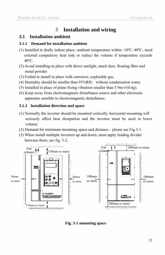
3.1.2 Installation direction and space
(1) Normally the inverter should be mounted vertically, horizontal mounting will seriously affect heat dissipation and the inverter must be used in lower volume.
(2) Demand for minimum mounting space and distance please see Fig.3-1. (3) When install multiple inverters up and down, must apply leading divider
between them, see fig. 3-2.
Fig. 3-1 mounting space
50mm or more
110mm or more
110mm or more
50mm or more
Fan exhaust
100mm or more
200mm or more
200mm or more
100mm or more
Fan exhaust
Shenzhen Gozuk Co., Limited www.gozuk.com---------------------------------------------------------------------------------------------------------------------------
12
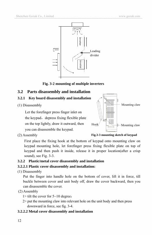
3.2 Parts disassembly and installation 3.2.1 Key board disassembly and installation
(1) Disassembly
Let the forefinger press finger inlet on the keypad depress fixing flexible plate on the top lightly, draw it outward, then you can disassemble the keypad.
(2) Assembly First place the fixing hook at the bottom of keypad onto mounting claw on keypad mounting hole, let forefinger press fixing flexible plate on top of keypad and then push it inside, release it in proper location(after a crisp sound), see Fig. 3-3.
3.2.2 Plastic/metal cover disassembly and installation 3.2.2.1 Plastic cover disassembly and installation: (1) Disassembly
Put the finger into handle hole on the bottom of cover, lift it in force, till buckle between cover and unit body off, draw the cover backward, then you can disassemble the cover.
(2) Assembly 1> tilt the cover for 5~10 degree 2> put the mounting claw into relevant hole on the unit body and then press
downward in force, see fig. 3-4. 3.2.2.2 Metal cover disassembly and installation
Mounting claw
Mounting clawHook
Fig.3-3 mounting sketch of keypad
Leading divider
Fig. 3-2 mounting of multiple inverters
Shenzhen Gozuk Co., Limited www.gozuk.com---------------------------------------------------------------------------------------------------------------------------
13
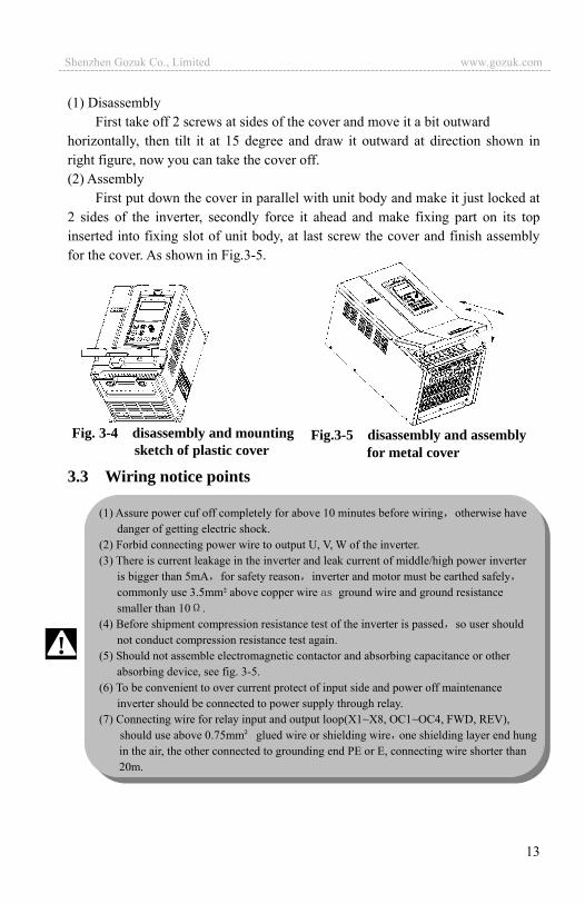
(1) Disassembly First take off 2 screws at sides of the cover and move it a bit outward
horizontally, then tilt it at 15 degree and draw it outward at direction shown in right figure, now you can take the cover off. (2) Assembly
First put down the cover in parallel with unit body and make it just locked at 2 sides of the inverter, secondly force it ahead and make fixing part on its top inserted into fixing slot of unit body, at last screw the cover and finish assembly for the cover. As shown in Fig.3-5.
3.3 wiring notice points 3.3 Wiring notice points
Fig. 3-4 disassembly and mounting sketch of plastic cover
Fig.3-5 disassembly and assembly for metal cover
(1) Assure power cuf off completely for above 10 minutes before wiring otherwise have danger of getting electric shock.
(2) Forbid connecting power wire to output U, V, W of the inverter. (3) There is current leakage in the inverter and leak current of middle/high power inverter
is bigger than 5mA for safety reason inverter and motor must be earthed safely commonly use 3.5mm² above copper wire ground wire and ground resistance smaller than 10 .
(4) Before shipment compression resistance test of the inverter is passed so user should not conduct compression resistance test again.
(5) Should not assemble electromagnetic contactor and absorbing capacitance or other absorbing device, see fig. 3-5.
(6) To be convenient to over current protect of input side and power off maintenance inverter should be connected to power supply through relay.
(7) Connecting wire for relay input and output loop(X1~X8, OC1~OC4, FWD, REV), should use above 0.75mm glued wire or shielding wire one shielding layer end hung in the air, the other connected to grounding end PE or E, connecting wire shorter than 20m.
!
Shenzhen Gozuk Co., Limited www.gozuk.com---------------------------------------------------------------------------------------------------------------------------

14
Fig.3-6 banned magnetic control conductor and absorbing capacitance between inverter and motor
3.4 Main loop terminal wiring
Fig.3-7 main loop simple wiring
3.4.1 Connection between inverter and fitting parts (1) Must assemble disjunction device such as isolation switch etc. between power
source and the inverter to assure personal safety when repairing the inverter and needing compulsory power off.
(2) Power supply loop must have breaker or fuse with over current protection function to avoid malfunction expanding caused by failure of after device.
(3) AC input reactor If high-order harmonics between inverter and power supply is biggish which can�t fulfil system requirement or need to improve input side power factor, AC input reactor is needed.
(4) Magnetic control conductor only be applied to power supply control and don�t apply magnetic control conductor to controlling on/off of the inverter.
3 phase AC power
supply
RS
T
U
W PE
V M
EDS1000 3 phase breaker
UEDS1000 V
W
M
!
(1) Before wiring, assure power supply is cut off completely for 10 minutes and all LED indicator light extinguished.
(2) Before internal wiring, confirm that DC volt. Between main loop end P+ and P- fall down to below DC36V.
(3) Wiring can only be done by professional person trained and qualified. (4) Before electrification, check if voltage grade of the inverter is in line with that of power
supply volt. otherwise will cause personnel injured and device damaged.
Shenzhen Gozuk Co., Limited www.gozuk.com---------------------------------------------------------------------------------------------------------------------------

15
(5) Input side EMI filter Can use EMI filter to inhibit
high-frequency conduction disturbance and emission disturbance from inverter power supply wire. (6) Output side EMI filter
Can use EMI filter to inhibit emission disturbance noise and wire leakage current from output side. (7) AC output reactor
Advise assembling AC output reactor to avoid motor insulation damage, too large over current and inverter frequent protection when connecting wire from inverter to motor exceeds 50m.But voltage drop of AC output reactor must be considered. Improve input output voltage of the inverter or let the motor in lower volume to avoid burning off the motor. (8) Complete ground wire
Inverter and motor must be earthed and grounding resistor smaller than 10 .Grounding wire should be shorter enough and wire diameter be bigger enough(not smaller than following standard):7.5KW or below motor: 3.5mm² above copper wire;11 15KW motor: 8mm² above copper wire. 18.5 37KW motor 14mm² above copper wire; 4555KW motor: 22mm² above copper wire.
M
RSTN
AC ouput reactor(in option)
Breaker or fuse
Braking resistor Brake unit (in option)
Fig.3-8 connection of inverter and fitting parts
Input EMI filter(in option)
Output EMI filter (in option)
Magnetic control conductor
AC input reactor(in option)
Isolation switch
V WPE U
R S T
EDS1000
Shenzhen Gozuk Co., Limited www.gozuk.com---------------------------------------------------------------------------------------------------------------------------
16
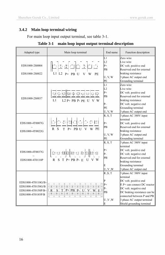
3.4.2 Main loop terminal wiring
For main loop input output terminal, see table 3-1.
Table 3-1 main loop input output terminal description
Adapted type Main loop terminal End name Function description
EDS1000-2S0004 ~
EDS1000-2S0022
L1 L2 P+ PB U, V, W PE
Zero wire Live wire DC volt. positive endReserved end for external braking resistance3 phase AC output end Grounding terminal
EDS1000-2S0037
L1 L2 P+ PB P- PE U, V, W
Zero wire Live wireDC volt. positive end Reserved end for external braking resistanceDC volt. negative endGrounding terminal3 phase AC output end
EDS1000-4T0007G ~
EDS1000-4T0022G
R, S, T P+ PB U, V, W PE
3 phase AC 380V input terminal DC volt. positive end Reserved end for external braking resistance 3 phase AC output end Grounding terminal
EDS1000-4T0037G ~
EDS1000-4T0110P
R, S, T P+ P- PB E U, V ,W
3 phase AC 380V input terminalDC volt. positive endDC volt. negative endReserved end for external braking resistance Grounding terminal3 phase AC output end
EDS1000-4T0110G/B~ EDS1000-4T0150G/B EDS1000-4T0150P/B~ EDS1000-4T0185P/B
R ,S, T P P+ P- PB U ,V ,W E
3 phase AC 380V input terminal DC volt. positive end P, P+ can connect DC reactorDC volt. negative endDC braking resistance can be connected between P and PB3 phase AC output terminalShield grounding terminal
R S T P+ PB P- U V WE
L1 L2 P+ PB P- U V WPE
R S T P+ PB P- U V W E
L1 L2 P+ PB U V W PE
R S T P+ PB V W PE U
Shenzhen Gozuk Co., Limited www.gozuk.com---------------------------------------------------------------------------------------------------------------------------

17
EDS1000-4T0185G~ EDS1000-4T0550G EDS1000-4T0220P~ EDS1000-4T0750P
R, S, T P P+ P- U, V, W E
3 phase AC 380V input terminal DC volt. positive end Reserved terminal for exterior DC reactor DC volt. negative end 3 phase AC output terminalShield grounding terminal
EDS1000-7T0185G~ EDS1000-7T1320G EDS1000-7T0220P~ EDS1000-7T1600P
P+ P P- R, S, T U, V, W PE
Reserved terminal for exterior DC reactor DC volt. positive end DC volt. negative end 3 phase AC 690V input terminal 3 phase AC output terminalShield grounding terminal
R S T P P+ P- U V W E
P+ P P- R S T U V W PE
(1) Can connect braking unit between P+ and P- externally if necessary. (2) Can connect DC braking resistor between PB and P+ externally if necessary. (3) DC reactor can be connected between P and P+ if necessary. (4) P and P+ must be short-circuited before shipment, otherwise the inverter can�t work.
note
Shenzhen Gozuk Co., Limited www.gozuk.com---------------------------------------------------------------------------------------------------------------------------
18
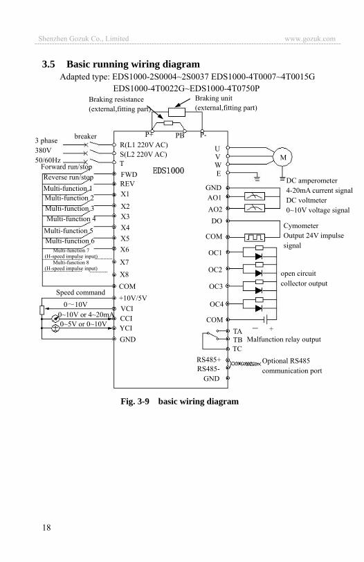
3.5 Basic running wiring diagram Adapted type: EDS1000-2S0004~2S0037 EDS1000-4T0007~4T0015G
EDS1000-4T0022G~EDS1000-4T0750P
Fig. 3-9 basic wiring diagram
P+ P-PBR(L1 220V AC)S(L2 220V AC)T
breaker
Forward run/stop Reverse run/stop Multi-function 1 Multi-function 2 Multi-function 3 Multi-function 4
Multi-function 5 Multi-function 6
Multi-function 7 (H-speed impulse input)
COM
FWDREV
X8
X7
X6X5X4X3X2
X1
U V W E
GND AO1 AO2
OC1
COM
TC RS485+
Malfunction relay output
M
Speed command +10V/5VVCICCIYCI0~5V or 0~10V
Multi-function 8 (H-speed impulse input)
COM
+
3 phase 380V 50/60Hz
OC3
OC4
Braking resistance (external,fitting part)
Braking unit (external,fitting part)
open circuit collector output
Cymometer Output 24V impulse signal
DC amperometer 4-20mA current signal DC voltmeter 0~10V voltage signal
GND
Optional RS485 communication port
GND RS485-
TB TA
OC2
DO
0 10V 0~10V or 4~20mA
Shenzhen Gozuk Co., Limited www.gozuk.com---------------------------------------------------------------------------------------------------------------------------
19
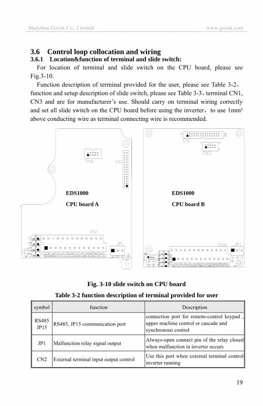
3.6 Control loop collocation and wiring 3.6.1 Location&function of terminal and slide switch:
For location of terminal and slide switch on the CPU board, please see Fig.3-10.
Function description of terminal provided for the user, please see Table 3-2function and setup description of slide switch, please see Table 3-3 terminal CN1, CN3 and are for manufacturer�s use. Should carry on terminal wiring correctly and set all slide switch on the CPU board before using the inverter to use 1mm² above conducting wire as terminal connecting wire is recommended.
Fig. 3-10 slide switch on CPU board
Table 3-2 function description of terminal provided for user
symbol function Description
RS485 JP15 RS485, JP15 communication port
connection port for remote-control keypad , upper machine control or cascade and synchronous control
JP1 Malfunction relay signal output Always-open connect pin of the relay closed when malfunction in inverter occurs
CN2 External terminal input output control Use this port when external terminal control inverter running
EDS1000
CPU board A
EDS1000
CPU board B
Shenzhen Gozuk Co., Limited www.gozuk.com---------------------------------------------------------------------------------------------------------------------------
20
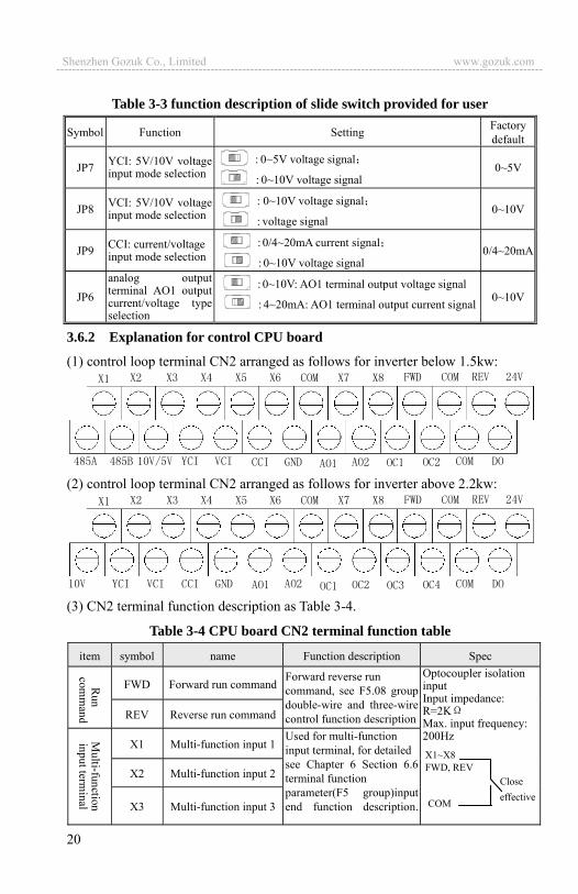
Table 3-3 function description of slide switch provided for user
Symbol Function Setting Factory default
JP7 YCI: 5V/10V voltage input mode selection
: 0~5V voltage signal
: 0~10V voltage signal 0~5V
JP8 VCI: 5V/10V voltage input mode selection
: 0~10V voltage signal
: voltage signal 0~10V
JP9 CCI: current/voltage input mode selection
: 0/4~20mA current signal
: 0~10V voltage signal 0/4~20mA
JP6 analog output terminal AO1 output current/voltage type selection
: 0~10V: AO1 terminal output voltage signal
: 4~20mA: AO1 terminal output current signal 0~10V
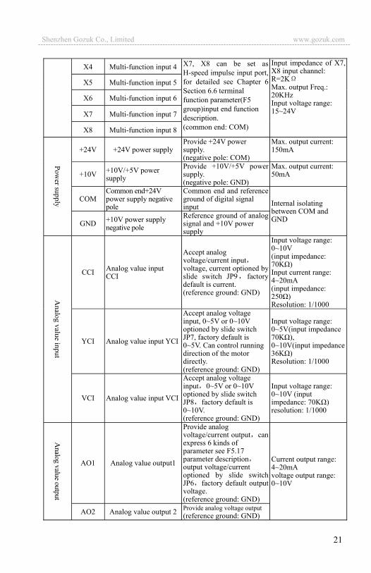
3.6.2 Explanation for control CPU board
(1) control loop terminal CN2 arranged as follows for inverter below 1.5kw:
(2) control loop terminal CN2 arranged as follows for inverter above 2.2kw:
(3) CN2 terminal function description as Table 3-4.
Table 3-4 CPU board CN2 terminal function table
item symbol name Function description Spec
FWD Forward run commandForward reverse run command, see F5.08 group double-wire and three-wire control function description
Optocoupler isolation input Input impedance: R=2K Max. input frequency: 200Hz
REV Reverse run command
X1 Multi-function input 1Used for multi-function input terminal, for detailedsee Chapter 6 Section 6.6 terminal function parameter(F5 group)input end function description.
X2 Multi-function input 2
X3 Multi-function input 3
X1~X8 FWD, REV
COM
Close effective
Shenzhen Gozuk Co., Limited www.gozuk.com---------------------------------------------------------------------------------------------------------------------------
21
X4 Multi-function input 4 X7, X8 can be set as H-speed impulse input port, for detailed see Chapter 6 Section 6.6 terminal function parameter(F5 group)input end function description. (common end: COM)
Input impedance of X7, X8 input channel: R=2K Max. output Freq.: 20KHz Input voltage range: 15~24V
X5 Multi-function input 5
X6 Multi-function input 6
X7 Multi-function input 7
X8 Multi-function input 8
+24V +24V power supply Provide +24V power supply. (negative pole: COM)
Max. output current:150mA
+10V +10V/+5V power supply
Provide +10V/+5V power supply. (negative pole: GND)
Max. output current:50mA
COM Common end+24Vpower supply negative pole
Common end and reference ground of digital signal input Internal isolating
between COM and GND GND +10V power supply
negative pole
Reference ground of analog signal and +10V power supply
CCI Analog value input CCI
Accept analog voltage/current input voltage, current optioned by slide switch JP9 factory default is current. (reference ground: GND)
Input voltage range: 0~10V (input impedance: 70K ) Input current range: 4~20mA (input impedance: 250 ) Resolution: 1/1000
YCI Analog value input YCI
Accept analog voltage input, 0~5V or 0~10V optioned by slide switch JP7, factory default is 0~5V. Can control running direction of the motor directly. (reference ground: GND)
Input voltage range: 0~5V(input impedance 70K ), 0~10V(input impedance36K ) Resolution: 1/1000
VCI Analog value input VCI
Accept analog voltage input 0~5V or 0~10V optioned by slide switch JP8 factory default is 0~10V. (reference ground: GND)
Input voltage range: 0~10V (input impedance: 70K ) resolution: 1/1000
AO1 Analog value output1
Provide analog voltage/current output can express 6 kinds of parameter see F5.17 parameter description output voltage/current optioned by slide switch JP6 factory default output voltage. (reference ground: GND)
Current output range: 4~20mA voltage output range: 0~10V
AO2 Analog value output 2 Provide analog voltage output (reference ground: GND)
Shenzhen Gozuk Co., Limited www.gozuk.com---------------------------------------------------------------------------------------------------------------------------
22
OC1 Open circuit collector output terminal 1 Used for multi-function
switch output terminal, fordetailed see Chapter 6 Section 6.6 terminal function parameter (F5 group) output end function description. (common end: COM)
optocoupler isolation output Work voltage range: 15~30V Max. output current: 50mA Use method see Description of parameter F5.10~F5.13
OC2 Open circuit collector output terminal 2
OC3 Open circuit collector output terminal 3
OC4 Open circuit collectoroutput terminal 4
DO H-speed impulse output terminal
Used for multi-function impulse signal output terminal, for detailed see Chapter 6 Section 6.6 terminal function parameter(F5 group) output end function description. (common end: COM)
Output impulse voltage: 24V Output frequency range:depending on parameter F5.24, max.20KHz
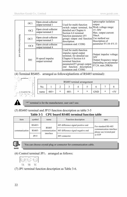
(4) Terminal RS485 arranged as follows(planform of RS485 terminal):
(5) RS485 terminal and JP15 function description as table 3-5
Table 3-5 CPU board RS485 terminal function tableitem symbol name Function description spec
communication
RS485+ RS485
communication interface
485 difference signal positive end For standard RS-485 communication interface please use twisted-pair or STP
RS485- 485 difference signal negative end
JP15 485 connector
(6) Control terminal JP1 arranged as follows:
(7) JP1 terminal function description as Table 3-6.
RS485 terninal arrangement
No. 1 2 3 4 5 6 7 8
name 485+ * 485- * * GND * +5V1 2 3 4 5 6 7 8
�*� terminal is for the manufacturer, user can�t use. !
note You can choose crystal plug or connector for communication cable.
Shenzhen Gozuk Co., Limited www.gozuk.com---------------------------------------------------------------------------------------------------------------------------
23
Table 3-6 CPU board JP1 terminal functionItem symbol name Function description Spec
Relay output
terminal
TA Inverter
malfunction output relay
Normal: TB-TC closed, TA-TC open Malfunction: TB-TC open, TA-TC closed
TB-TC: always-closed, TA-TC: always-open Contact capacity: AC250V/2A (COS =1) AC250V/1A (COS =0.4) DC30V/1A
TB
TC
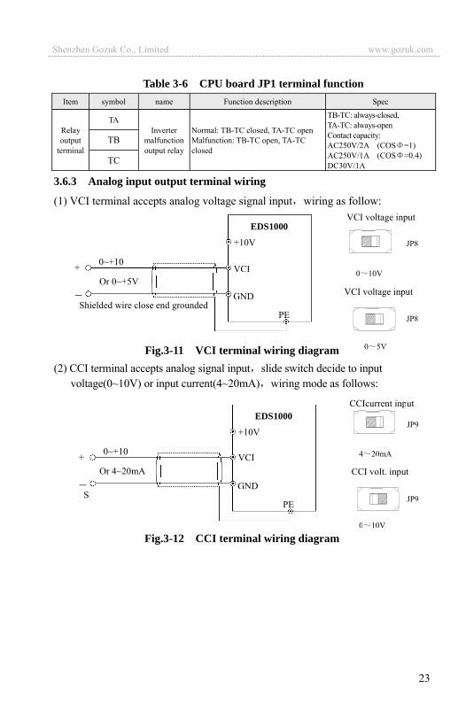
3.6.3 Analog input output terminal wiring
(1) VCI terminal accepts analog voltage signal input wiring as follow:
Fig.3-11 VCI terminal wiring diagram (2) CCI terminal accepts analog signal input slide switch decide to input
voltage(0~10V) or input current(4~20mA) wiring mode as follows:
Fig.3-12 CCI terminal wiring diagram
+10V
VCI
GND
PE
EDS1000
0~+10+ Or 0~+5V
Shielded wire close end grounded
VCI voltage input
VCI voltage input
JP8
JP8
0 10V
0 5V
CCIcurrent input
CCI volt. input
JP9
JP9
4 20mA
0 10V
Shielded wire close end grounded
+10V
VCI
GND
PE
EDS1000
0~+10+ Or 4~20mA
Shenzhen Gozuk Co., Limited www.gozuk.com---------------------------------------------------------------------------------------------------------------------------

24
(3) YCI terminal accepts analog voltage signal input wiring mode as follows:
Fig.3-13 YCI terminal wiring diagram
Explanation: relation between YCI input voltage and set frequency is as following figure:
1> when YCI input voltage is 0~10V:
2> when YCI input voltage is 0~5V:
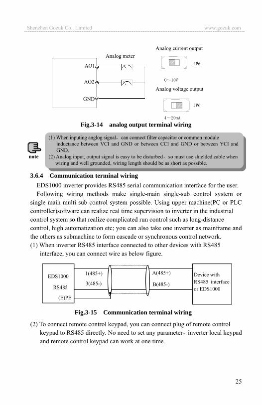
(4) wiring of analog output terminals AO1, AO2 Analog output terminals AO1, AO2 connected to analog meter and kinds
of physical data can be indicated, thereinto AO1 can output current (4~20mA) or voltage (0~10V) decided by slide switch JP6. Terminal wiring mode as Fig.3-13.
10V
5V
0V
V
f(Hz)
high limit frequency (REV)
+high limit frequency (FWD)
5V
2.5V
0V
V
f(Hz)
high limit frequency (REV)
+ high limit frequency (FWD)
+10V
VCI
GND
PE
EDS1000
0~+10+ Or 0~+5V
Shielded wire close end grounded
YCI current input
YCI volt.
JP7
JP7
0 5V
0 10V
Shenzhen Gozuk Co., Limited www.gozuk.com---------------------------------------------------------------------------------------------------------------------------
25
Fig.3-14 analog output terminal wiring
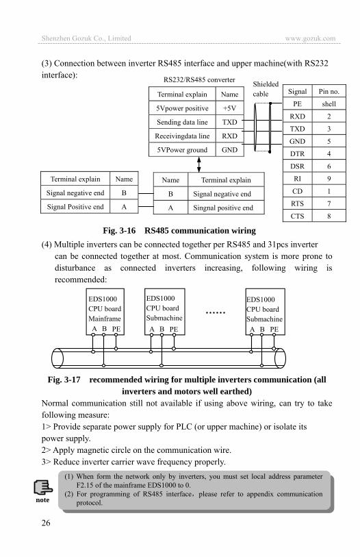
3.6.4 Communication terminal wiring EDS1000 inverter provides RS485 serial communication interface for the user. Following wiring methods make single-main single-sub control system or
single-main multi-sub control system possible. Using upper machine(PC or PLC controller)software can realize real time supervision to inverter in the industrial control system so that realize complicated run control such as long-distance control, high automatization etc; you can also take one inverter as mainframe and the others as submachine to form cascade or synchronous control network. (1) When inverter RS485 interface connected to other devices with RS485
interface, you can connect wire as below figure.
(2) To connect remote control keypad, you can connect plug of remote control
keypad to RS485 directly. No need to set any parameter inverter local keypad and remote control keypad can work at one time.
Analog meter
AO1
AO2
GND
Analog current output
Analog voltage output
JP6
JP6
(1) When inputing anglog signal can connect filter capacitor or common module inductance between VCI and GND or between CCI and GND or between YCI and GND.
(2) Analog input, output signal is easy to be disturbed so must use shielded cable when wiring and well grounded, wiring length should be as short as possible.
note
EDS1000
RS485
Device with RS485 interface or EDS1000
A(485+)
B(485-)
1(485+) 3(485-)
(E)PE
Fig.3-15 Communication terminal wiring
Shenzhen Gozuk Co., Limited www.gozuk.com---------------------------------------------------------------------------------------------------------------------------
26
(3) Connection between inverter RS485 interface and upper machine(with RS232 interface):
Fig. 3-16 RS485 communication wiring (4) Multiple inverters can be connected together per RS485 and 31pcs inverter
can be connected together at most. Communication system is more prone to disturbance as connected inverters increasing, following wiring is recommended:
Fig. 3-17 recommended wiring for multiple inverters communication (all inverters and motors well earthed)
Normal communication still not available if using above wiring, can try to take following measure: 1> Provide separate power supply for PLC (or upper machine) or isolate its power supply. 2> Apply magnetic circle on the communication wire. 3> Reduce inverter carrier wave frequency properly.
RS232/RS485 converter Signal Pin no.
PE shell
RXD 2
TXD 3
GND 5
DTR 4
DSR 6
RI 9
CD 1
RTS 7
CTS 8
Terminal explain Name
5Vpower positive +5V
Sending data line TXD
Receivingdata line RXD
5VPower ground GND
Name Terminal explain
B Signal negative end
A Singnal positive end
Terminal explain Name
Signal negative end B
Signal Positive end A
Shielded cable
EDS1000 CPU board Mainframe
A B PE
EDS1000 CPU board Submachine
EDS1000 CPU board Submachine
A B PE A B PE
……
(1) When form the network only by inverters, you must set local address parameter F2.15 of the mainframe EDS1000 to 0.
(2) For programming of RS485 interface please refer to appendix communication protocol. note
Shenzhen Gozuk Co., Limited www.gozuk.com---------------------------------------------------------------------------------------------------------------------------
27
3.7 Installation guide for anti-jamming Main circuit of the inverter is composed of high-power semiconductor switch
gear so some electromagnetic noise will arise during work to reduce or stop disturbance to environment show you assembling method of inverter disturbance suppressing from many aspects such as disturbance suppressing, spot wiring, system grounding, leak current, usage of power supply filter etc. in this section to be referred to during spot assembling. 3.7.1 Restraining to noise disturbance
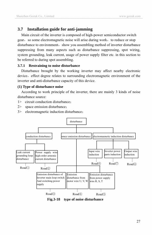
Disturbance brought by the working inverter may affect nearby electronic device effect degree relates to surrounding electromagnetic environment of the inverter and anti-disturbance capacity of this device. (1) Type of disturbance noise
According to work principle of the inverter, there are mainly 3 kinds of noise disturbance source: 1> circuit conduction disturbance 2> space emission disturbance 3> electromagnetic induction disturbance
Fig.3-18 type of noise disturbance
disturbance
Emission disturbance from motor wire U, V, W
Emission disturbancefrom power supply wire R, S, T
Emission disturbance of Inverter main loop switch And switching power supply
conduction disturbance space emission disturbance electromagnetic induction disturbance
Leak current grounding loop disturbance
Power supply wirehigh-order armoniccurrent disturbance
Road
Road
Road Road
Road Road
Road
Input wire induction
Inverter power parts induction
Output wire induction
Road
Shenzhen Gozuk Co., Limited www.gozuk.com---------------------------------------------------------------------------------------------------------------------------

28
(2) Noise spread road
Fig.3-19 noise disturbance spread road sketch (3) basic countermeasure for suppressing disturbance
Table 3-7 disturbance suppressing countermeasure table Noise spread road
Countermeasure of weakening effect
When grounding wire of peripheral device and wiring of the inverter compose closed-loop, inverter grounding wire leakage current would make the device do wrong action. Can reduce wrong action if the device is not earthed here. High-order harmonic from the inverter would make voltage and current transmit through power supply wire when peripheral device and the inverter electrified by same power supply, would disturb other devices in this same power supply systemcan take following suppressing measure: assemble electromagnetic noise filter at inverter input end isolate other devices by isolation transformer; connect power supply for peripheral device with remote power source; install ferrite filter magnetic circle for R, S, T three-phase conducting wire of the inverter to suppress conduction of high-frequency harmonic current.
Keep device and signal wire prone to disturbance from the inverter. Should use shielded signal wire, shielding layer single end earthed and try best to keep away from the inverter and its input, output wire. If signal wire must intersect strong power cable, must keep them in real intersection and avoid parallel.
Install high-frequency noise filter(ferrite common module choke, folksay magnetic circle) separately at input, output root which can effectively suppress emission disturbance from dynamic wire.
Should place motor cable shield of biggish thickness, for instance set it in tube with biggish thickness (above 2mm) or bury it in cement slot. Dynamic wire set into metal tube and use shielding wire to be grounded (use 4-core motor cable, one side is earthed through the inverter, the other side connected to motor shell).
power supply inverterWireless set meter
motor sensor
TV
Shenzhen Gozuk Co., Limited www.gozuk.com---------------------------------------------------------------------------------------------------------------------------
29
To prevent parallel or bundled power and weak conducting wire should keep away from inverter mounted device to the best and its wiring should keep away from power wire of the inverter such as R, S, T, U, V, W etc.. Should pay attention to relative mounting place between device with strong electric field or strong magnetic field and the inverter, should keep distance and vertical intersection.
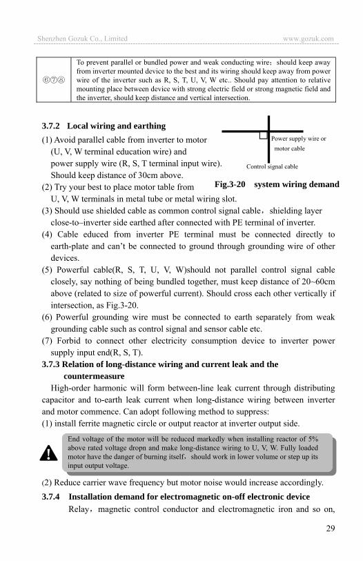
3.7.2 Local wiring and earthing (1) Avoid parallel cable from inverter to motor
(U, V, W terminal education wire) and power supply wire (R, S, T terminal input wire). Should keep distance of 30cm above.
(2) Try your best to place motor table from U, V, W terminals in metal tube or metal wiring slot.
(3) Should use shielded cable as common control signal cable shielding layer close-to�inverter side earthed after connected with PE terminal of inverter.
(4) Cable educed from inverter PE terminal must be connected directly to earth-plate and can�t be connected to ground through grounding wire of other devices.
(5) Powerful cable(R, S, T, U, V, W)should not parallel control signal cable closely, say nothing of being bundled together, must keep distance of 20~60cm above (related to size of powerful current). Should cross each other vertically if intersection, as Fig.3-20.
(6) Powerful grounding wire must be connected to earth separately from weak grounding cable such as control signal and sensor cable etc.
(7) Forbid to connect other electricity consumption device to inverter power supply input end(R, S, T).
3.7.3 Relation of long-distance wiring and current leak and the countermeasure
High-order harmonic will form between-line leak current through distributing capacitor and to-earth leak current when long-distance wiring between inverter and motor commence. Can adopt following method to suppress: (1) install ferrite magnetic circle or output reactor at inverter output side.
(2) Reduce carrier wave frequency but motor noise would increase accordingly. 3.7.4 Installation demand for electromagnetic on-off electronic device
Relay magnetic control conductor and electromagnetic iron and so on,
Power supply wire or motor cable
Control signal cable
Fig.3-20 system wiring demand
End voltage of the motor will be reduced markedly when installing reactor of 5% above rated voltage dropn and make long-distance wiring to U, V, W. Fully loaded motor have the danger of burning itself should work in lower volume or step up its input output voltage.
!
Shenzhen Gozuk Co., Limited www.gozuk.com---------------------------------------------------------------------------------------------------------------------------

30
these electromagnetic on-off electronic device would bring lots of noise during work, so you should pay full attention to when installing them beside the inverter or in the same control chamber with the inverter and must install surge absorbing device as shown in Fig. 3-21.
Fig.3-21 installation demand for electromagnetic on-off device
Inverter or other electric apparatus
Voltage-sensible resistor
diode
RC-filter
220VAC
220VAC
24VDC +
_
Shenzhen Gozuk Co., Limited www.gozuk.com---------------------------------------------------------------------------------------------------------------------------

31
4 Run and operation explanation for inverter 4.1 Run of inverter 4.1.1 Running order channels
There are 3 kinds of order channel for controlling run action of the inverter such as run, stop, jog etc.:
0: keypad
Control by key , , on keypad(factory default).
1: Control terminal Use control terminal FWD, REV, COM to make of double-line control oruse one terminal of X1 X8 and FWD or REV to make of three-line control. 2: Serial portControl run and stop of the inverter through upper machine or other device which can communicate with the inverter. Choose order channel by setting function code F0.02 and also can choose by multi-function input terminal(F5.00~F5.07 choose function 29, 30, 31).
4.1.2 Frequency-provision channel EDS1000 common run mode there are 10 kinds of provision channel: 0: keypad analog potentiometer provision1: direct digital frequency provision2: terminal UP/DOWN provision(store after power-off or stop)3: serial port provision4: analog value VCI provision5: analog value CCI provision6: analog value YCI provision7: terminal pulse(PULSE) provision8: combination set; 9: terminal UP/DOWN provision(not store after power-off or stop)
4.1.3 Work state Work state of EDS1000 is classified as waiting state and running state:
waiting state: If there is no running command after the inverter electrified or after stop command during running state, the inverter enters into waiting state. running state: the inverter enters into running state after receiving run command.
Please make switching debugging in advance when switch the order channel to check if it can fulfil system requirement otherwise have danger of damaging device and injuring personal.
!
Shenzhen Gozuk Co., Limited www.gozuk.com---------------------------------------------------------------------------------------------------------------------------
32
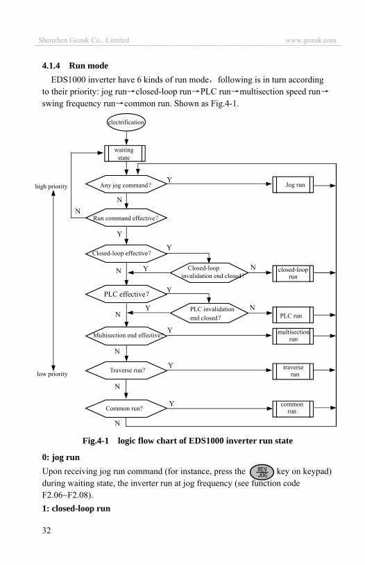
4.1.4 Run modeEDS1000 inverter have 6 kinds of run mode following is in turn according
to their priority: jog run closed-loop run PLC run multisection speed runswing frequency run common run. Shown as Fig.4-1.
0: jog run Upon receiving jog run command (for instance, press the key on keypad) during waiting state, the inverter run at jog frequency (see function code F2.06~F2.08).1: closed-loop run
Fig.4-1 logic flow chart of EDS1000 inverter run state
high priority Jog run
PLC run
closed-loop run
multisectionrun
traverse run
electrification
waitingstate
Any jog command
Run command effective
Closed-loop effective
PLC effective
Multisection end effective?
PLC invalidation end closed
Closed-loop invalidation end closed
low priority
N
Traverse run? Y
Y
Y
Y
Y
Y
Y
Y
N
N
N
N
N
N
N
common runCommon run?
Y
N
Shenzhen Gozuk Co., Limited www.gozuk.com---------------------------------------------------------------------------------------------------------------------------
33
The inverter will come into closed-loop run mode when closed –loop run control effective parameter is set(F3.00=1). Namely carry on PID adjustment to specified value and feedback value(proportion integral differential calculation see F3 group function code) and PID adjustor output is inverter output frequency. Can make closed-loop run mode ineffective and switch to lower level run mode by multi-function terminal (function 20). 2: PLC runThe inverter will enter into PLC run mode and run according to run mode preset(see F4 group function code description) through setting PLC function effective parameter(F4.00 last bit 0). Can make PLC run mode ineffective and switch to lower level run mode by multi-function terminal (function 21). 3: multi-section speed runBy nonzero combination of multi-function terminal(1, 2, 3, 4 function) choosemultisection frequency 1~7(F2.30~F2.36) to run at multisection speed. 4: swing frequency runThe inverter will enter into swing frequency run mode when swing frequency function effective parameter(F6.00=1)is set. Set relevant swing frequency run special parameter according to textile swing frequency craft to realize swing frequency run. 5: common run Common open loop run mode of general inverter. In above 6 kinds of run mode except “jog run” the inverter can run according to kinds of frequency setting method. In PID run PLC run multisection run
common run mode the inverter can also carry on pendular frequency adjustment.
Shenzhen Gozuk Co., Limited www.gozuk.com---------------------------------------------------------------------------------------------------------------------------

34
4.2 Operation and use of key board 4.2.1 Keypad layout
Keypad is main unit for receiving command, displaying parameter. Outer dimension of EN-KB6 is as Fig.4-2:
Fig.4-2 keypad layout sketch 4.2.2 Keypad function description
There are 8 key-presses and one adjusting button for analog potentiometer on inverter Keypad and function definition of each key is as shown in table 4-1.
Table 4-1 keypad function table
key name Function description
Program/Exit key Enter into or exit programming state
Shift/Supervision key
Can choose modification digit of set data under editor state can switch display status supervision parameter under other state.
Function/Data key Enter into the next menu or data confirmation
Rev/Jog key Under keypad mode, to press this key can set reverse run or Jog run according to the 2nd bit of parameter F0.03
Run key Enter into forward run under keypad mode
Stop/reset key
In common run status the inverter will be stopped according to set mode after pressing this key if run command channel is set as keypad stop effective mode. The inverter will be reset and resume normal stop status after pressing this key when the inverter is in malfunction status.
Frequency unit(Hz)
Current unit(A) Reverse run indicator light
Forward run indicator light Failure alarm indicator light
Mode indicator light
Rev/Jog key Program, exit key
Stop, reset key Run key
Shift/supervision
Confirm/data key
Analog potentiometer
Digital display (LED)
Data modification key
Voltage unit(V)
Shenzhen Gozuk Co., Limited www.gozuk.com---------------------------------------------------------------------------------------------------------------------------
35
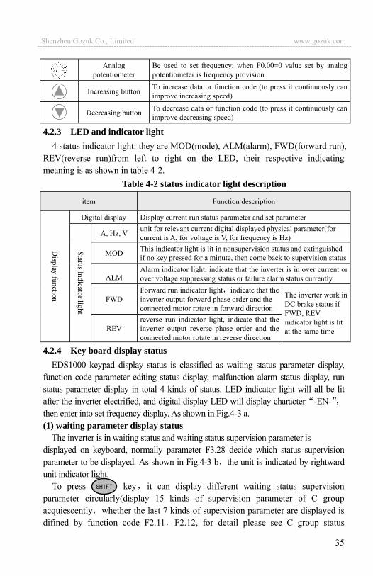
Analog potentiometer
Be used to set frequency; when F0.00=0 value set by analog potentiometer is frequency provision
Increasing button To increase data or function code (to press it continuously can improve increasing speed)
Decreasing button To decrease data or function code (to press it continuously can improve decreasing speed)
4.2.3 LED and indicator light 4 status indicator light: they are MOD(mode), ALM(alarm), FWD(forward run),
REV(reverse run)from left to right on the LED, their respective indicating meaning is as shown in table 4-2.
Table 4-2 status indicator light description
item Function description
Digital display Display current run status parameter and set parameter
A, Hz, V unit for relevant current digital displayed physical parameter(for current is A, for voltage is V, for frequency is Hz)
MOD This indicator light is lit in nonsupervision status and extinguished if no key pressed for a minute, then come back to supervision status
ALM Alarm indicator light, indicate that the inverter is in over current or over voltage suppressing status or failure alarm status currently
FWD Forward run indicator light indicate that the inverter output forward phase order and the connected motor rotate in forward direction
The inverter work in DC brake status if FWD, REV indicator light is lit at the same time REV
reverse run indicator light, indicate that the inverter output reverse phase order and the connected motor rotate in reverse direction
4.2.4 Key board display status EDS1000 keypad display status is classified as waiting status parameter display,
function code parameter editing status display, malfunction alarm status display, run status parameter display in total 4 kinds of status. LED indicator light will all be lit after the inverter electrified, and digital display LED will display character -EN-then enter into set frequency display. As shown in Fig.4-3 a. (1) waiting parameter display status
The inverter is in waiting status and waiting status supervision parameter is displayed on keyboard, normally parameter F3.28 decide which status supervision parameter to be displayed. As shown in Fig.4-3 b the unit is indicated by rightward unit indicator light.
To press key it can display different waiting status supervision parameter circularly(display 15 kinds of supervision parameter of C group acquiescently whether the last 7 kinds of supervision parameter are displayed is difined by function code F2.11 F2.12, for detail please see C group status
Shenzhen Gozuk Co., Limited www.gozuk.com---------------------------------------------------------------------------------------------------------------------------

36
supervision parameter in function parameter schedule graph of chapter 5). (2) run parameter display status
The inverter enters into run status when receiving effective run command and normally parameter F3.28 decide which status supervision parameter to be displayed on the keypad. As shown in Fig.4-3 c unit is displayed by rightward unit indicator light.
To press key can display run status supervision parameter circularly (defined by function code F2.11 and F2.12). During displaying, can press to switch to initial supervision parameter decided by F3.28, otherwise will display the last displayed parameter all along.
Fig.4-3 inverter electrification, waiting, run status display
(3) Failure alarm display status The inverter enters into failure alarm display
status upon detecting failure signal and display failure code sparklingly(as shown in Fig.4-4); To press key can look over relative parameter after stopping running Canpress key to enter into program status to see about Fd group parameter if want to search failure information. Can carry on failure restoration by key, control terminal or communication command on the keypad after troubleshooting. Keep displaying failure code if failure exist continuously.
over current in accelerating
Fig.4-4 failure alarm
electrificationdisplay-EN-
waiting status display waiting status parameter
run status, display run status parameterFig.a Fig.b Fig.c
Set frequency Output frequency
For some serious failure such as inverse module protect over current, over voltage etc., must not carry on failure reset forcibly to make the inverter run again without failure elimination confirmed. Otherwise have danger of damaging the inverter
!
Shenzhen Gozuk Co., Limited www.gozuk.com---------------------------------------------------------------------------------------------------------------------------
37
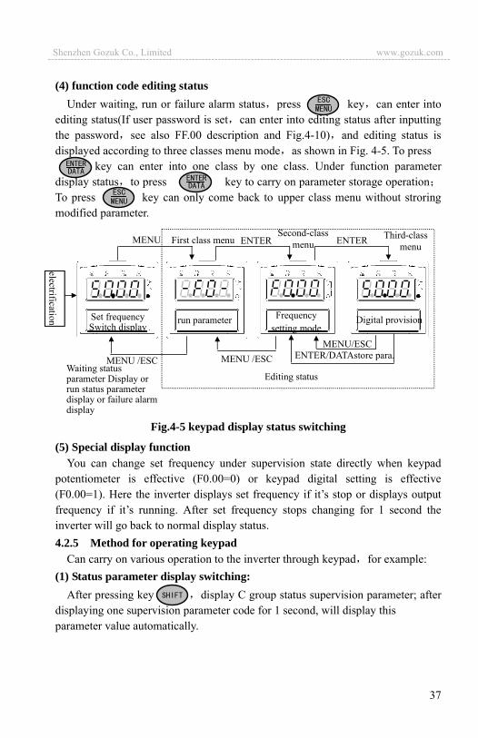
(4) function code editing status Under waiting, run or failure alarm status press key can enter into
editing status(If user password is set can enter into editing status after inputting the password see also FF.00 description and Fig.4-10) and editing status is displayed according to three classes menu mode as shown in Fig. 4-5. To press
key can enter into one class by one class. Under function parameter display status to press key to carry on parameter storage operationTo press key can only come back to upper class menu without stroring modified parameter.
Fig.4-5 keypad display status switching
(5) Special display function You can change set frequency under supervision state directly when keypad
potentiometer is effective (F0.00=0) or keypad digital setting is effective (F0.00=1). Here the inverter displays set frequency if it’s stop or displays output frequency if it’s running. After set frequency stops changing for 1 second the inverter will go back to normal display status. 4.2.5 Method for operating keypad
Can carry on various operation to the inverter through keypad for example: (1) Status parameter display switching:
After pressing key display C group status supervision parameter; after displaying one supervision parameter code for 1 second, will display this parameter value automatically.
ENTER ENTER MENU Second-class
menu First class menu Third-class menu
MENU/ESC
MENU /ESC ENTER/DATAstore para.
Editing status Waiting status parameter Display or run status parameter display or failure alarm display
Set frequency Switch display
run parameter Frequency setting mode
Digital provision
MENU /ESC
Shenzhen Gozuk Co., Limited www.gozuk.com---------------------------------------------------------------------------------------------------------------------------

38
Fig. 4-6 waiting status parameter display operating example Description: 1> All status parameters C-00 C-14 can be displayed when the inverter leaves
factory. You can make a change by modifying function code F2.11, F2.12 if you want to, for detail please refer to F2.11, F2.12function code description.
2> Can press key to switch into constant supervision C-01 display status directly when the user see about status supervision parameter.
(2) Function code parameter setting Take function code F2.06 modified from 5.00Hz to 6.00Hz as example.
Boldface in Fig.4-7 shows flickering digit.
Fig.4-7 example for parameter setting and modification Description: under third-class menu, if the parameter has no blinking digit this function code can’t be modified possible reasons are as follows: 1> This function code shouldn’t be modified, for example actual detected status
parameter, run record parameter etc.2> This function code can’t be modified under run status and can be changed
after stopping running
50.00 -F0- -F2- F2.00 F2.06
05.00-F2-
Key-press operation order Enter into
editing Status display first-class menu
Choose F2 groupfunction
code
Function group confirmation go into second-class menu
Choose function code F2.06
Go back to First-class
menu
Exit editing status
Store modified value,back to second-class menuDisplay next function code
LEDdisplayed content
05.00F2.07 06.00
Function code confirmation, Enter into third-class menu
Parameter modification, Choose parameterdigit
Parameter modification, 5 6
LED displayed content
1s 1s50.00 C-01
Set frequencyKey-press operation order
Output frequency Output current
Output voltagePulse input
Para. value C-02 Para. value
C-031s
parameterC-141s
parameter
Shenzhen Gozuk Co., Limited www.gozuk.com---------------------------------------------------------------------------------------------------------------------------

39
3> Parameter protected. All the function code can’t be modified when function code F2.13=1 or 2 in order to avoid wrong operation. Need to set the function code F2.13 to 0 if you want to edit function code parameter.
(3) Specified frequency adjustment for common run Take example modifying specified frequency from 50.00Hz to 40.00Hz at
F0.00=0 during running for explanation.
Fig. 4-8 set frequency adjustment operation example
(4) Jog run operation For example, keypad as current run command channel, jog run frequency 5Hz,
waiting status.
Fig.4-9 Jog run operating example (5) Operation for entering to function code editing status after setting user
password “user password”FF.00 is set to 6886 . Boldfaced digit in Fig.4-7 shows
blinking bit.
Fig.4-10 inputting password to go into function code operation
0.0.0.6 6.0.0.60.0.0.050.00 0.0.0.6
6.8.0.6 6.0.0.66.8.8.6-F0- 6.8.0.6
Nonediting status
user passwordeffective, go intopassword validation status
At first last Digit flash, Increase to 6
move cursor position to first digit
Increase to 6
Increase to 8
Increase to 8
Move to second digit
Press confirmation Key, pass validation, Go into editing status
Move to third digit
LED displayed contentKey-press operation order
5.00 50.000.0150.00 release
waiting waiting
Display run output frequency
Output frequency Increased by 5Hz
LED displayed content
Key-press operation order Display
set frequency
presskeep
Output frequencyFall down to 0HzStop running
0.01
50.00 45.00 40.00
Press decreasingbutton for one time
Adjust frequency based on requirement
49.99
Stop pressing after set value reached, go back to normal display statusafter 1 second
LED displayed contentKey-press operation order
Shenzhen Gozuk Co., Limited www.gozuk.com---------------------------------------------------------------------------------------------------------------------------

40
(6) See about failure parameter under failure status:
Fig.4-11 failure status searching operation exampleDescription: 1> If press key under failure status the user can see about Fd group function code parameter, search range Fd.06 Fd.14 LED first display function code number when the user press key and display parameter digit of this function code after 1s. 2> When the user see about failure parameter can press key directly to switch back to failure alarm display status (E0XX)
(7) keypad key-press locking operation
Under unlocked keypad situation press key for 5s to lock the keypad. For detailed operation please refer to 2nd bit of F2.13 function code.
(8) keypad key-press unlocking operation
Under locked keypad situation press key for 5s to unlock the keypad.
1s 1s 1s
1s
E001 Fd.06 50:00 Fd.07 45:00 Fd.08 5.5
Fd.09380Fd.1311111s
Fd.1415001s
Failure set freq. Failure output freq. Failure current
Failure output volt.Failure terminal statusFailure run time
LED displayed content
Key-press operation order
Shenzhen Gozuk Co., Limited www.gozuk.com---------------------------------------------------------------------------------------------------------------------------
41
4.3 Inverter electrification 4.3.1 Check before electrification
Please carry on wiring based on operation requirement provided in “inverter wiring” of this Service manual.
4.3.2 First electrification Close input side AC power
supply switch after correct wiring and power supply confirmed, electrify the inverter and keypad LED display “-EN-”, contactor closed normally, LED displayed set frequency shows that electrification is finished. First electrification operation process is shown as figure in the page.
Fig. 4-12 first electrification operation flow
display-EN-
Hear contactor closed sound
display set frequency?
cut off power
success
check reason
failure
Y
Y
Y
Y
N
N
N
start
wiring based on 3.5 section
wiring correct?
input voltage correct?
electrify
Y
Y
N
N
Shenzhen Gozuk Co., Limited www.gozuk.com---------------------------------------------------------------------------------------------------------------------------
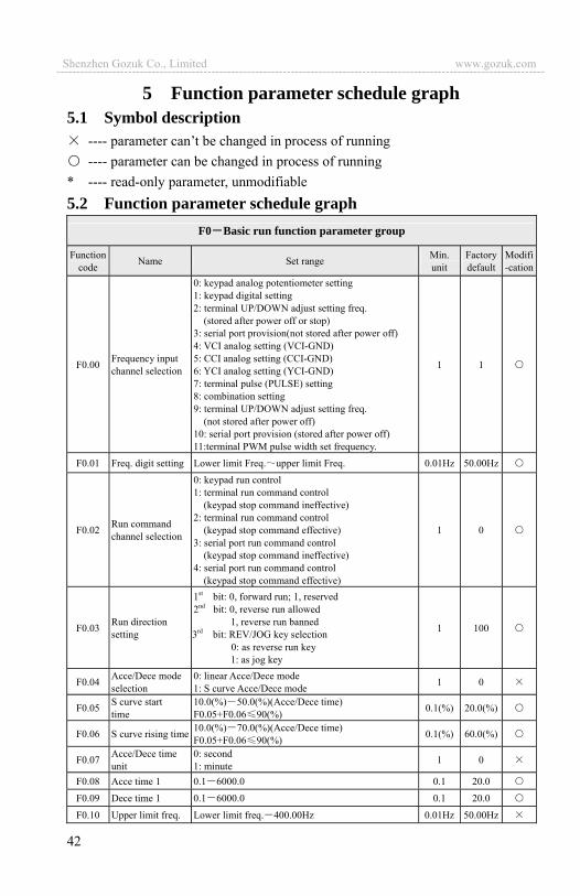
42
5 Function parameter schedule graph5.1 Symbol description
---- parameter can’t be changed in process of running ---- parameter can be changed in process of running
* ---- read-only parameter, unmodifiable 5.2 Function parameter schedule graph
F0 Basic run function parameter group
Functioncode Name Set range Min.
unit Factory default
Modifi-cation
F0.00 Frequency input channel selection
0: keypad analog potentiometer setting 1: keypad digital setting 2: terminal UP/DOWN adjust setting freq.
(stored after power off or stop) 3: serial port provision(not stored after power off) 4: VCI analog setting (VCI-GND) 5: CCI analog setting (CCI-GND) 6: YCI analog setting (YCI-GND) 7: terminal pulse (PULSE) setting 8: combination setting 9: terminal UP/DOWN adjust setting freq. (not stored after power off) 10: serial port provision (stored after power off) 11:terminal PWM pulse width set frequency.
1 1
F0.01 Freq. digit setting Lower limit Freq. upper limit Freq. 0.01Hz 50.00Hz
F0.02 Run command channel selection
0: keypad run control 1: terminal run command control
(keypad stop command ineffective) 2: terminal run command control
(keypad stop command effective) 3: serial port run command control
(keypad stop command ineffective) 4: serial port run command control
(keypad stop command effective)
1 0
F0.03 Run direction setting
1st bit: 0, forward run; 1, reserved 2nd bit: 0, reverse run allowed 1, reverse run banned
3rd bit: REV/JOG key selection 0: as reverse run key 1: as jog key
1 100
F0.04 Acce/Dece mode selection
0: linear Acce/Dece mode 1: S curve Acce/Dece mode 1 0
F0.05 S curve start time
10.0(%) 50.0(%)(Acce/Dece time) F0.05+F0.06 90(%) 0.1(%) 20.0(%)
F0.06 S curve rising time 10.0(%) 70.0(%)(Acce/Dece time) F0.05+F0.06 90(%) 0.1(%) 60.0(%)
F0.07 Acce/Dece time unit
0: second 1: minute 1 0
F0.08 Acce time 1 0.1 6000.0 0.1 20.0
F0.09 Dece time 1 0.1 6000.0 0.1 20.0
F0.10 Upper limit freq. Lower limit freq. 400.00Hz 0.01Hz 50.00Hz
Shenzhen Gozuk Co., Limited www.gozuk.com---------------------------------------------------------------------------------------------------------------------------
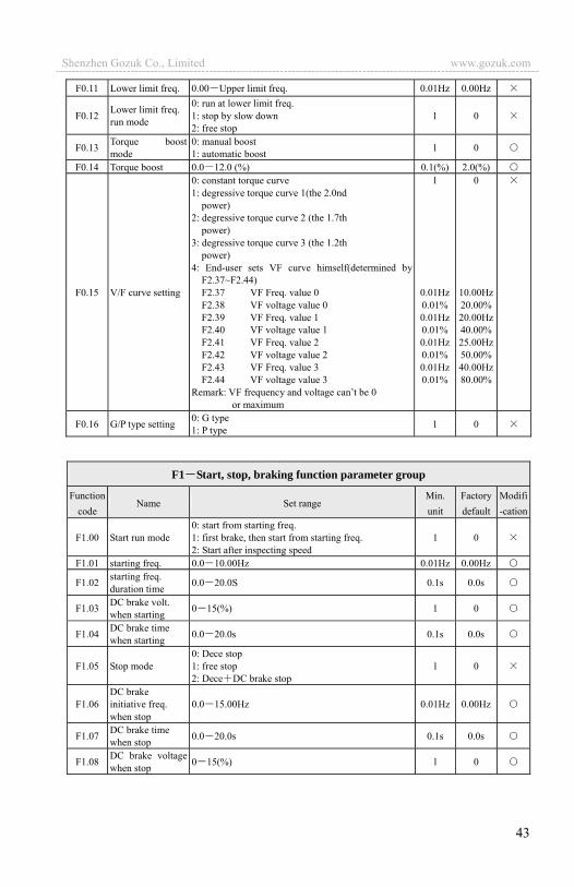
43
F0.11 Lower limit freq. 0.00 Upper limit freq. 0.01Hz 0.00Hz
F0.12 Lower limit freq. run mode
0: run at lower limit freq. 1: stop by slow down 2: free stop
1 0
F0.13 Torque boost mode
0: manual boost 1: automatic boost 1 0
F0.14 Torque boost 0.0 12.0 (%) 0.1(%) 2.0(%)
F0.15 V/F curve setting
0: constant torque curve 1: degressive torque curve 1(the 2.0nd
power) 2: degressive torque curve 2 (the 1.7th
power) 3: degressive torque curve 3 (the 1.2th
power) 4: End-user sets VF curve himself(determined by
F2.37~F2.44) F2.37 VF Freq. value 0 F2.38 VF voltage value 0 F2.39 VF Freq. value 1 F2.40 VF voltage value 1 F2.41 VF Freq. value 2 F2.42 VF voltage value 2 F2.43 VF Freq. value 3 F2.44 VF voltage value 3 Remark: VF frequency and voltage can’t be 0
or maximum
1
0.01Hz0.01%0.01Hz0.01%0.01Hz0.01%0.01Hz0.01%
0
10.00Hz20.00%20.00Hz40.00%25.00Hz50.00%40.00Hz80.00%
F0.16 G/P type setting 0: G type 1: P type 1 0
F1 Start, stop, braking function parameter group
Functioncode
Name Set range Min. unit
Factory default
Modifi-cation
F1.00 Start run mode 0: start from starting freq. 1: first brake, then start from starting freq. 2: Start after inspecting speed
1 0
F1.01 starting freq. 0.0 10.00Hz 0.01Hz 0.00Hz
F1.02 starting freq. duration time 0.0 20.0S 0.1s 0.0s
F1.03 DC brake volt. when starting 0 15(%) 1 0
F1.04 DC brake time when starting 0.0 20.0s 0.1s 0.0s
F1.05 Stop mode 0: Dece stop 1: free stop 2: Dece DC brake stop
1 0
F1.06 DC brake initiative freq. when stop
0.0 15.00Hz 0.01Hz 0.00Hz
F1.07 DC brake time when stop 0.0 20.0s 0.1s 0.0s
F1.08 DC brake voltage when stop 0 15(%) 1 0
Shenzhen Gozuk Co., Limited www.gozuk.com---------------------------------------------------------------------------------------------------------------------------

44
F2 Auxiliary run function parameter group Function
code Name Set range Min. unit
Factory default
Modifi-cation
F2.00 Analog filter time constant 0.00 30.00s 0.01s 0.20s
F2.01 Forward reverse run dead-section time
0.0 3600.0s 0.1s 0.1s
F2.02 Automatic energy save run
0: no action 1: action 1 0
F2.03 AVR function 0: no action 1: action all the time 2: no action only during Dec
1 0
F2.04 Slip frequency compensation 0 150(%)0-no slip frequency compensation 1 0
F2.05 Carrier wave freq. 2 15.0K 0.1K
dependon
machine type
F2.06 Jog run frequency 0.10 50.00Hz 0.01Hz 5.00HzF2.07 Jog Acce time 0.1 60.0s 0.1s 20.0sF2.08 Jog Dece time 0.1 60.0s 0.1s 20.0s
F2.09 Frequency input channelcombination
0: VCI CCI 1: VCI CCI 2: YCI CCI 3: RS485+YCI 4: VCI YCI 5: reserved 6: exterior pulse provision CCI 7: exterior pulse provision CCI 8: reserved 9: reserved 10: reserved 11: reserved 12: reserved 13: VCI CCI any nonzero value effective, VCI
preferred 14: reserved 15: RS485+CCI 16: RS485-CCI 17: RS485+VCI 18: RS485-VCI 19: RS485+keypad potentiometer 20: RS485- keypad potentiometer 21: VCI+ keypad potentiometer 22: VCI- keypad potentiometer 23: CCI+ keypad potentiometer 24: CCI- keypad potentiometer 25: reserved 26: reserved 27: reserved 28: reserved
1 0
F2.10
Main & sub invertercommunication frequency provisionproportion
0 500(%) 1(%) 100(%)
Shenzhen Gozuk Co., Limited www.gozuk.com---------------------------------------------------------------------------------------------------------------------------
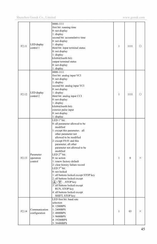
45
F2.11 LED display control 1
0000-1111 first bit: running time 0: not display 1: display second bit: accumulative time 0: not display 1: display third bit: input terminal status 0: not display 1: display kilobit(fourth bit): output terminal status 0: not display 1: display
1 1111
F2.12 LED display control 2
0000-1111 first bit: analog input VCI 0: not display 1: display second bit: analog input YCI 0: not display 1: display third bit: analog input CCI 0: not display 1: display kilobit(fourth bit): exterior pulse input 0: not display 1: display
1 1111
F2.13 Parameter operation control
LED 1st bit: 0: all parameter allowed to be
modified 1: except this parameter all
other parameter not allowed to be modified
2: except F0.01 and this parameter, all other parameter not allowed to be modified
LED 2nd bit: 0: no action 1: renew factory default 2: clear history failure record LED 3rd bit: 0: not locked 1: all buttons locked except STOP key 2: all buttons locked except
, STOP key 3: all buttons locked except RUN, STOP key 4: all buttons locked except SHIFT, STOP key
1 0
F2.14 Communication configuration
LED first bit: baud rate selection 0: 1200BPS 1: 2400BPS 2: 4800BPS 3: 9600BPS 4: 19200BPS 5: 38400BPS
1 03
Shenzhen Gozuk Co., Limited www.gozuk.com---------------------------------------------------------------------------------------------------------------------------

46
LED second bit: data format 0: 1 8 1format, no checkout 1: 1 8 1 format,
even checkout 2: 1 8 1 format,
odd checkout
F2.15 Local address 0 127 127 is broadcast address. The inverter only receive but not send when it is set to be 127, 0 is address for main device.
1 1
F2.16 Communication overtime checkout time
0.0 1000.0s 0.1s 0.0s
F2.17 Local response delay time 0 1000ms 1ms 5ms
F2.18 Acce time 2 0.1 6000.0 0.1 20.0 F2.19 Dece time 2 0.1 6000.0 0.1 20.0 F2.20 Acce time 3 0.1 6000.0 0.1 20.0 F2.21 Dece time 3 0.1 6000.0 0.1 20.0 F2.22 Acce time 4 0.1 6000.0 0.1 20.0 F2.23 Dece time 4 0.1 6000.0 0.1 20.0 F2.24 Acce time 5 0.1 6000.0 0.1 20.0 F2.25 Dece time 5 0.1 6000.0 0.1 20.0 F2.26 Acce time 6 0.1 6000.0 0.1 20.0 F2.27 Dece time 6 0.1 6000.0 0.1 20.0 F2.28 Acce time 7 0.1 6000.0 0.1 20.0 F2.29 Dece time 7 0.1 6000.0 0.1 20.0 F2.30 Muti-step freq. 1 Lower limit freq. upper limit freq. 0.01Hz 5.00HzF2.31 Muti-step freq. 2 Lower limit freq. upper limit freq. 0.01Hz 10.00HzF2.32 Muti-step freq. 3 Lower limit freq. upper limit freq. 0.01Hz 20.00HzF2.33 Muti-step freq. 4 Lower limit freq. upper limit freq. 0.01Hz 30.00HzF2.34 Muti-step freq. 5 Lower limit freq. upper limit freq. 0.01Hz 40.00HzF2.35 Muti-step freq. 6 Lower limit freq. upper limit freq. 0.01Hz 45.00HzF2.36 Muti-step freq. 7 Lower limit freq. upper limit freq. 0.01Hz 50.00Hz
F2.37 VF frequency value 0 0.00-F2.39 0.01Hz 10.00Hz
F2.38 VF voltage value 0 0.00-F2.40 0.01% 20.00%
F2.39 VF frequency value 1 F2.37-F2.41 0.01Hz 20.00Hz
F2.40 VF voltage value 1 F2.38-F2.42 0.01% 40.00%
F2.41 VF frequency value 2 F2.39-F2.43 0.01Hz 25.00Hz
F2.42 VF voltage value 2 F2.40-F2.44 0.01% 50.00%
F2.43 VF frequency value 3 F2.41-high limit frquency 0.01Hz 40.00Hz
F2.44 VF voltage value 3 F2.42-100.0% (rated voltage) 0.01% 80.00%
F2.45 Jumping freq. 1 0.00 400.00Hz 0.01Hz 0.00Hz
F2.46 Jumping freq. 1 range 0.00 30.00Hz 0.01Hz 0.00Hz
F2.47 Jumping freq. 2 0.00 400.00Hz 0.01Hz 0.00Hz
F2.48 Jumping freq. 2 range 0.00 30.00Hz 0.01Hz 0.00Hz
F2.49 Jumping freq. 3 0.00 400.00Hz 0.01Hz 0.00Hz
Shenzhen Gozuk Co., Limited www.gozuk.com---------------------------------------------------------------------------------------------------------------------------

47
F2.50 Jumping freq. 3 range 0.00 30.00Hz 0.01Hz 0.00Hz
F2.51 Sett run time 0 65535 hours 1 0
F2.52 Run time accumulation 0 65535 hours 1 0 *
F2.53
RS485/232 communication frame format selection
0: a ASCII frame of 14 byte or 18 byte 1: a hex frame of 8 byte or 10 byte, original response
not changed 2: a hex frame of 8 byte or 10 byte, 12 command has
no response 3: a hex frame of 8 byte or 10 byte, 14 command has
no response 4: a hex frame of 8 byte or 10 byte, both 12 and 14
command have no response
1 0
F3 Closed-loop run function parameter group Function
code Name Set range Min. unit
Factory default
Modifi-cation
F3.00 Closed-loop run control selection
0: closed-loop control ineffective 1: PID closed-loop control effective 2:constant pressure water supply PID control
effective(F5.10 F5.13 must be set to 21)
1 0
F3.01 Provision channel selection
0: digital provision 1: VCI analog 0 10V voltage provision 2: CCI analog provision 3: keypad analog potentiometer provision
1 1
F3.02 Feedback channel selection
0: VCI analog input voltage 0 10V 1: CCI analog input 2: VCI+CCI 3: VCI-CCI 4: Min { VCI, CCI } 5: Max { VCI, CCI } 6: pulse feedback
1 1
F3.03
Specified value digital setting 0.000~9.999V(setF3.00=1,F3.21=9.999) 0.001 1.000
Target pressure value setting 0.000~F3.21Mpa(setF3.00=2) 0.001 1.000
F3.04 Minimum specified value
0.0 maximum specified value; percentage relative to 10.00V 0.1(%) 0.000
F3.05
Corresponding feedback value responding of minimum specified value
0.0 100.0(%) 0.1(%) 0.000
F3.06 maximum specified value
Minimum specified value 100.0(%) 0.1(%) 100.0(%)
F3.07
Corresponding feedback value responding of maximum specified value
0.0 100.0(%) 0.1(%) 100.0(%)
F3.08 proportion gain Kp 0.000 9.999 0.001 0.050F3.09 Integral gain Ki 0.000 9.999 0.001 0.050
F3.10 Differential gain Kd 0.000 9.999 0.001 0.000
Shenzhen Gozuk Co., Limited www.gozuk.com---------------------------------------------------------------------------------------------------------------------------

48
F3.11 Sampling cycle T 0.01 1.00s 0.01s 0.10sF3.12 Deviation limit 0.0 20.0(%)percentage relative to 10.00V 0.1(%) 2.0(%)
F3.13 Integral separation PID adjusting threshold
0.0 100.0% 0.1% 100.0%
F3.14 Closed-lop preset frequency 0 upper limit frequency 0.01Hz 00.00
F3.15 Closed-loop preset frequency holding time
0.0 6000s 0.1s 000.0
F3.16 Sleep frequency threshold 0.00 400.00Hz 0.01Hz 30.00
F3.17 Wake pressure threshold 0.000 F3.21Mpa 0.001 0.500
F3.18 Sleep delay time 0.0 6000.0s 0.1 000.0F3.19 Revival delay time 0.0 6000.0s 0.1 000.0
F3.20 Constant pressure water supply mode 1
0: inverter works in one-drive-two water supply mode1: constant pressure water supply board acts in
one-drive-two mode 2: constant pressure water supply board acts in
one-drive-three mode 3: constant pressure water supply board acts in
one-drive-four mode
1 0
F3.21 Long-distance manometer range 0.001 9.999Mpa 0.001 9.999
F3.22
Allowed offset to upper limit frequency and lower limit frequency when add or reduce pumps
0.1 100.0% 0.1 001.0
F3.23 Pump switch judging time 0.0 999.9s 0.1 005.0
F3.24 Magnetic control conductor switch delay time
0.1 10.0s 0.1 00.5
F3.25 Automatic switch intervel 0000 9999minutes 1 0000
F3.26 Water supply supervision parameter display
0: C-11, C-12 denote voltage value of VCI, CCI 1: C-11, C-12 denote PID specified pressure and
feedback pressure 1 0
F3.27 Closed-loop adjustingcharacteristic
0: Forward function 1: Reverse function 0
F3.28
LED initial supervision parameter selection
0: set frequency 1: output frequency 2: output current 3: output voltage 4: DC bus bar voltage 5: motor speed 6: heat sink temperature 7: run time 8: accumulative run time 9: input terminal status 10: output terminal status 11: analog input VCI/PID provision 12: analog input CCI/PID feedback
1
Shenzhen Gozuk Co., Limited www.gozuk.com---------------------------------------------------------------------------------------------------------------------------
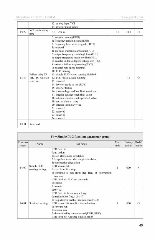
49
13: analog input YCI 14: exterior pulse inputs
F3.29 YCI run-in delay time 0.0 999.9s 0.0 10.0
F3.30 Failure relay TATB TC function selection
0: inverter running(RUN) 1: frequency arriving signal(FAR) 2: frequency level detect signal (FDT1) 3: reserved 4: overload warning alarm signal (OL) 5: output frequency reach high limit(FHL) 6: output frequency reach low limit(FLL) 7: inverter under voltage blockage stop (LU) 8: external failure stop-running(EXT) 9: inverter zero speed running 10: PLC running 11: simple PLC section running finished 12: PLC finish a cycle running 13: reserved 14: inverter ready to run (RDY) 15: inverter failure 16: traverse high and low limit restriction 17: interior counter reach final value 18: interior counter reach specified value 19: set run time arriving 20: interior timing arriving 21: reserved 22: reserved 23: reserved 24: reserved
15
F3.31 Reserved
F4 Simple PLC function parameter group
Functioncode Name Set range Min.
unit Factory default
Modifi-cation
F4.00 Simple PLC running setting
LED first bit: 0: no action 1: stop after single circulation 2: keep final value after single circulation 3: consecutive circulation LED second bit: 0: start from first step 1: continue to run from step freq. of interruption
moment LED third bit: PLC run time unit 0: second 1: minute
1 000
F4.01 Section 1 setting
000 621 LED first bit: frequency setting 0: multisection freq. i (i=1~7) 1: freq. determined by function code F0.00 LED second bit: run direction selection 0: forward run 1: reverse run 2: determined by run command(FWD, REV) LED third bit: Acc/Dec time selection
1 000
Shenzhen Gozuk Co., Limited www.gozuk.com---------------------------------------------------------------------------------------------------------------------------
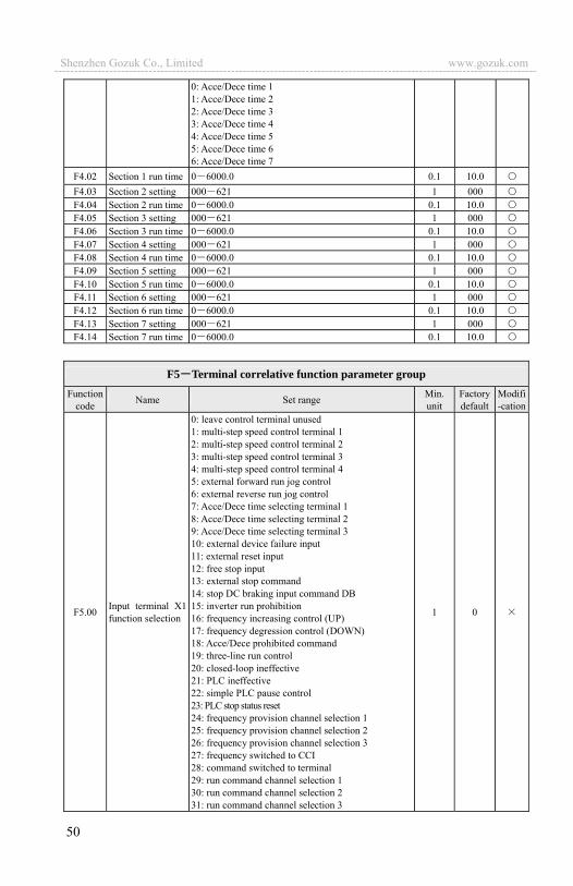
50
0: Acce/Dece time 1 1: Acce/Dece time 2 2: Acce/Dece time 3 3: Acce/Dece time 4 4: Acce/Dece time 5 5: Acce/Dece time 6 6: Acce/Dece time 7
F4.02 Section 1 run time 0 6000.0 0.1 10.0 F4.03 Section 2 setting 000 621 1 000 F4.04 Section 2 run time 0 6000.0 0.1 10.0 F4.05 Section 3 setting 000 621 1 000 F4.06 Section 3 run time 0 6000.0 0.1 10.0 F4.07 Section 4 setting 000 621 1 000 F4.08 Section 4 run time 0 6000.0 0.1 10.0 F4.09 Section 5 setting 000 621 1 000 F4.10 Section 5 run time 0 6000.0 0.1 10.0 F4.11 Section 6 setting 000 621 1 000 F4.12 Section 6 run time 0 6000.0 0.1 10.0 F4.13 Section 7 setting 000 621 1 000 F4.14 Section 7 run time 0 6000.0 0.1 10.0
F5 Terminal correlative function parameter group Function
code Name Set range Min.unit
Factory default
Modifi-cation
F5.00 Input terminal X1 function selection
0: leave control terminal unused 1: multi-step speed control terminal 1 2: multi-step speed control terminal 2 3: multi-step speed control terminal 3 4: multi-step speed control terminal 4 5: external forward run jog control 6: external reverse run jog control 7: Acce/Dece time selecting terminal 1 8: Acce/Dece time selecting terminal 2 9: Acce/Dece time selecting terminal 3 10: external device failure input 11: external reset input 12: free stop input 13: external stop command 14: stop DC braking input command DB 15: inverter run prohibition 16: frequency increasing control (UP) 17: frequency degression control (DOWN) 18: Acce/Dece prohibited command 19: three-line run control 20: closed-loop ineffective 21: PLC ineffective 22: simple PLC pause control 23: PLC stop status reset 24: frequency provision channel selection 1 25: frequency provision channel selection 2 26: frequency provision channel selection 3 27: frequency switched to CCI 28: command switched to terminal 29: run command channel selection 1 30: run command channel selection 2 31: run command channel selection 3
1 0
Shenzhen Gozuk Co., Limited www.gozuk.com---------------------------------------------------------------------------------------------------------------------------

51
32: swing frequency jump-in 33: external interruption input 34: interior counter clearing end 35: interior counter triggering end 36: interior timer clearing end 37: interior timer triggering end 38: pulse frequency input(only effective forX7,X8) 39: reserved 40: reserved 41: reserved 42: reserved
F5.01 Input terminal X2 function selection Same as above
F5.02 Input terminal X3 function selection Same as above
F5.03 Input terminal X4 function selection Same as above
F5.04 Input terminal X5 function selection Same as above
F5.05 Input terminal X6 function selection Same as above
F5.06 Input terminal X7 function selection Same as above
F5.07 Input terminal X8 function selection Same as above
F5.08 FWD/REV run mode selection
0: 2-wire control mode 1 1: 2-wire control mode 2 2: 3-wire control mode 1 3: 3-wire control mode 2
1 0
F5.09 UP/DOWN velocity 0.01 99.99Hz/s 0.01Hz/s 1.00Hz/s
F5.10
Open circuit collector output terminal OC1 output setting
0: inverter running signal(RUN) 1: frequency arriving signal(FAR) 2: frequency level detect signal (FDT1) 3: reserved 4: overload warning signal (OL) 5: output frequency reach high limit(FHL) 6: output frequency reach low limit(FLL) 7: inverter under voltage blockage stop (LU) 8: stop for exterior failure(EXT) 9: inverter zero rotate speed running 10: PLC running 11: simple PLC segment running finished 12: PLC finish one cycle run 13: reserved 14: inverter ready to run (RDY) 15: inverter failure 16: swing frequency high&low limit restriction 17: interior counter reach final value 18: interior counter reach specified value 19: set runtime arrive 20: interior timing arrive 21: OC1-variable frequency for the 1st pump
OC2-power source for the 1st pump OC3- variable frequency for the 2nd pump OC4-power source for the 2nd pump
22: reserved 23: reserved
1 0
Shenzhen Gozuk Co., Limited www.gozuk.com---------------------------------------------------------------------------------------------------------------------------

52
24: reserved
F5.11
Open circuit collector output terminal OC2 output setting
Same as above 1 0
F5.12
Open circuit collector output terminal OC3 output setting
Same as above 1 0
F5.13
Open circuit collector output terminal OC4 output setting
Same as above 1 0
F5.14 Frequency arriving (FAR) detect range 0.00 50.00Hz 0.01Hz 5.00Hz
F5.15 FDT1 (frequency level) electric level 0.00 high limit frequency 0.01Hz 10.00Hz
F5.16 FDT1 lag 0.00 50.00Hz 0.01Hz 1.00Hz
F5.17 Analog output (AO1) selection
0: output frequency(0 high limit frequency) 1: set frequency(0 high limit frequency) 2: output current(0 2×rated current) 3: output voltage(0 1.2×load motor rated voltage) 4: bus-bar voltage(0 800V) 5: PID provision (0.00-10.00V) 6: PID feedback (0.00-10.00V) 7: reserved 8: reserved 9: reserved
1 0
F5.18 Analog output (AO1) gain 0.00 2.00 0.01 1.00
F5.19 Analog output (AO1) offset 0.00 10.00V 0.01 0.00
F5.20 Analog output (AO2) selection Same as F5.17 1 0
F5.21 Analog output (AO2) gain 0.10 2.00 0.01 1.00
F5.22 Analog output (AO2) offset 0.00 10.00V 0.01 0.00
F5.23 DO terminal output function selection
Same as F5.17 1 0
F5.24 DO maximum pulse output frequency
0.1 20.0(max. 20KHz)Max. DO port output pulse frequency corresponds to Max. value selected by F5.23
0.1KHz 10.0
F5.25 Set interior count number arriving provision
0 9999 1 0
F5.26 Specified interior count number arriving provision
0 9999 1 0
F5.27 Interior timer setting 0.1 6000.0s 0.1 60.0
Shenzhen Gozuk Co., Limited www.gozuk.com---------------------------------------------------------------------------------------------------------------------------
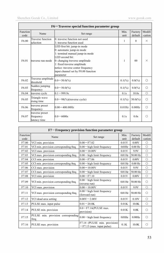
53
F6 Traverse special function parameter group Function
code Name Set range Min.unit
Factory default
Modifi-cation
F6.00 Traverse function selection
0: traverse function not used 1: traverse function used 1 0
F6.01 traverse run mode
LED first bit: jump-in mode 0: automatic jump-in mode 1: terminal manual jump-in mode LED second bit: 0: changing traverse amplitude 1: fixed traverse amplitude notice: traverse center frequency input channel set by F0.00 function parameter
1 00
F6.02 Traverse amplitude threshold 0.0 50.0(%) 0.1(%) 0.0(%)
F6.03 Sudden jumping frequency 0.0 50.0(%) 0.1(%) 0.0(%)
F6.04 traverse cycle 0.1 999.9s 0.1s 10.0s
F6.05 Triangle wave rising time 0.0 98(%)(traverse cycle) 0.1(%) 50.0(%)
F6.06 traverse preset frequency 0.00 400.00Hz 0.01Hz 0.00Hz
F6.07 traverse preset frequency latency time
0.0 6000s 0.1s 0.0s
F7 Frequency provision function parameter group Function
code Name Set range Min. unit
Factory default
Modifi-cation
F7.00 VCI min. provision 0.00 F7.02 0.01V 0.00VF7.01 VCI min. provision corresponding freq. 0.00 high limit frequency 0.01Hz 0.00 HzF7.02 VCI max. provision 0.00 10.00V 0.01V 9.9V F7.03 VCI max. provision corresponding freq. 0.00 high limit frequency 0.01 Hz 50.00 HzF7.04 CCI min. provision 0.00 F7.06 0.01V 0.00VF7.05 CCI min. provision corresponding freq. 0.00 high limit frequency 0.01 Hz 0.00 HzF7.06 CCI max. provision 0.00 10.00V 0.01V 9.9V F7.07 CCI max. provision corresponding freq. 0.00 high limit frequency 0.01 Hz 50.00 HzF7.08 YCI min. provision 0.00 F7.10 0.01V 0.00V
F7.09 YCI min. provision corresponding freq. 0.00 high limit frequency (reverse run) 0.01 Hz 50.00 Hz
F7.10 YCI max. provision 0.00 10.00V 0.01V 9.9V
F7.11 YCI max. provision corresponding freq. 0.00 high limit frequency (forward run) 0.01 Hz 50.00 Hz
F7.12 YCI dead area setting 0.00V 2.00V 0.01V 0.10V
F7.13 PULSE max. input pulse 0.01 20.0K 0.01K 10.0K
F7.14 PULSE min. provision 0.0 F7.16(PULSE max. provision) 0.01K 0.0K
F7.15 PULSE min. provision correspondingfreq. 0.00 high limit frequency 0.01Hz 0.00Hz
F7.16 PULSE max. provision F7.14 (PULSE min. provision)F7.13 (max. input pulse) 0.1K 10.0K
Shenzhen Gozuk Co., Limited www.gozuk.com---------------------------------------------------------------------------------------------------------------------------

54
F7.17 PULSE max. provision correspondingfreq. 0.00 high limit frequency 0.01 Hz 50.00 Hz
F8 Motor and vector control parameter group Function
code Name Set range Min.unit
Factory default
Modifi-cation
F8.00 Control mode setting 0: V/F control1: vector control remark: for EDS1300 it can’t be 1
1 0
F8.01 Motor rated voltage 1 480V 1V Depend on device type
F8.02 Motor rated current 0.1 999.9A 0.1A Depend on device type
F8.03 Motor rated frequency 1.00 400.00Hz 0.01 Hz Depend on device type
F8.04 Motor rated speed 1 9999r/min 1r/min Depend on device type
F8.05 Motor pole quantity 2 14 2 Depend on device type
F8.06 Motor rated power 0.1 999.9KW 0.1 Depend on device type
F8.07 Motor stator resistance 0.000 9.9999ohm 0.001 ohm Depend on device type
F8.08 Motor rotor resistance 0.000 9.9999ohm 0.001 ohm Depend on device type
F8.09 Motor stator leakage inductance 0.0 999.9mH 0.1 mH Depend on device type
F8.10 Motor rotor leakage inductance 0.0 999.9mH 0.1 mH Depend on device type
F8.11 Motor mutual inductance 0.0 999.9mH 0.1 mH Depend on device type
F8.12 Torque limit 50.0 200.0%(rated current) 0.1% 150.0% F8.13 Speed loop proportion gain 0.000 6.000 0.001 0.700 F8.14 Speed loop integral time constant 0.000 9.999 0.001 0.360 F8.15 Motor stability coefficient 0 4 3 F8.16 Filter time displayed instead freq. 0~999 1 6 F8.17 Motor speed correction factor 0 9999% 0 100%
F9 Protection function parameter group
Functioncode Name Set range Min.
unit Factory default
Modifi-cation
F9.00 Waiting time for starting again when power off
0.0 20.0S (0 means do not enable this function) 0.1S 0
F9.01 Failure self-renew times
0 100 shows no automatic reset function Note:no automatic reset function when over
load and over heat.1 0
F9.02 Failure self-renew interval 0.5 20.0S 0.1S 5.0S
F9.03 Motor overload protection mode selection
0: no action 1: inverter close off output 1 1
F9.04 Motor overload protection coefficient 20.0 120.0(%) 0.1(%) 100.0(%)
Shenzhen Gozuk Co., Limited www.gozuk.com---------------------------------------------------------------------------------------------------------------------------
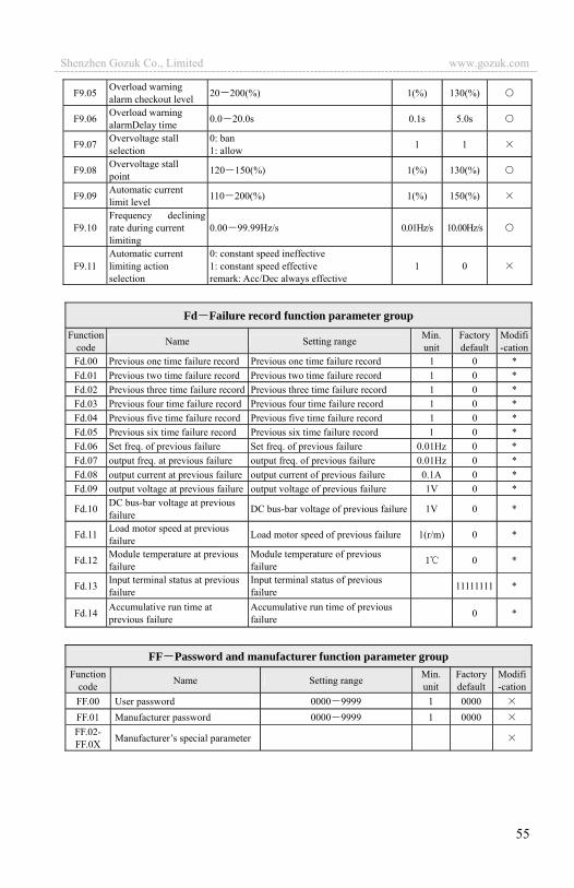
55
F9.05 Overload warning alarm checkout level 20 200(%) 1(%) 130(%)
F9.06 Overload warning alarmDelay time 0.0 20.0s 0.1s 5.0s
F9.07 Overvoltage stall selection
0: ban 1: allow 1 1
F9.08 Overvoltage stall point 120 150(%) 1(%) 130(%)
F9.09 Automatic current limit level 110 200(%) 1(%) 150(%)
F9.10 Frequency declining rate during current limiting
0.00 99.99Hz/s 0.01Hz/s 10.00Hz/s
F9.11 Automatic current limiting action selection
0: constant speed ineffective 1: constant speed effective remark: Acc/Dec always effective
1 0
Fd Failure record function parameter group Function
code Name Setting range Min. unit
Factory default
Modifi-cation
Fd.00 Previous one time failure record Previous one time failure record 1 0 * Fd.01 Previous two time failure record Previous two time failure record 1 0 * Fd.02 Previous three time failure record Previous three time failure record 1 0 * Fd.03 Previous four time failure record Previous four time failure record 1 0 * Fd.04 Previous five time failure record Previous five time failure record 1 0 * Fd.05 Previous six time failure record Previous six time failure record 1 0 * Fd.06 Set freq. of previous failure Set freq. of previous failure 0.01Hz 0 * Fd.07 output freq. at previous failure output freq. of previous failure 0.01Hz 0 * Fd.08 output current at previous failure output current of previous failure 0.1A 0 * Fd.09 output voltage at previous failure output voltage of previous failure 1V 0 *
Fd.10 DC bus-bar voltage at previous failure DC bus-bar voltage of previous failure 1V 0 *
Fd.11 Load motor speed at previous failure Load motor speed of previous failure 1(r/m) 0 *
Fd.12 Module temperature at previousfailure
Module temperature of previous failure 1 0 *
Fd.13 Input terminal status at previousfailure
Input terminal status of previous failure 11111111 *
Fd.14 Accumulative run time at previous failure
Accumulative run time of previous failure 0 *
FF Password and manufacturer function parameter group Function
code Name Setting range Min.unit
Factory default
Modifi-cation
FF.00 User password 0000 9999 1 0000 FF.01 Manufacturer password 0000 9999 1 0000 FF.02- FF.0X Manufacturer’s special parameter
Shenzhen Gozuk Co., Limited www.gozuk.com---------------------------------------------------------------------------------------------------------------------------
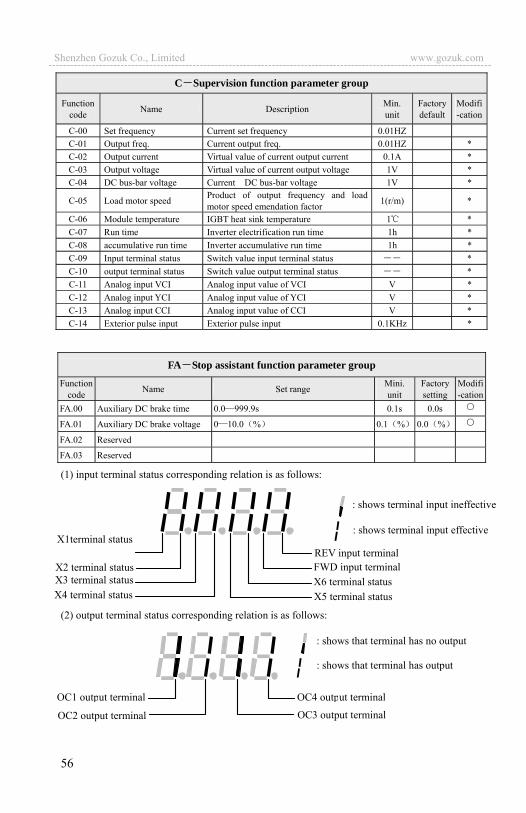
56
C Supervision function parameter group
Function code Name Description Min.
unit Factory default
Modifi-cation
C-00 Set frequency Current set frequency 0.01HZ C-01 Output freq. Current output freq. 0.01HZ * C-02 Output current Virtual value of current output current 0.1A * C-03 Output voltage Virtual value of current output voltage 1V * C-04 DC bus-bar voltage Current DC bus-bar voltage 1V *
C-05 Load motor speed Product of output frequency and load motor speed emendation factor 1(r/m) *
C-06 Module temperature IGBT heat sink temperature 1 * C-07 Run time Inverter electrification run time 1h * C-08 accumulative run time Inverter accumulative run time 1h * C-09 Input terminal status Switch value input terminal status * C-10 output terminal status Switch value output terminal status * C-11 Analog input VCI Analog input value of VCI V * C-12 Analog input YCI Analog input value of YCI V * C-13 Analog input CCI Analog input value of CCI V * C-14 Exterior pulse input Exterior pulse input 0.1KHz *
FA Stop assistant function parameter group Function
code Name Set range Mini. unit
Factorysetting
Modifi-cation
FA.00 Auxiliary DC brake time 0.0 999.9s 0.1s 0.0s
FA.01 Auxiliary DC brake voltage 0 10.0 % 0.1 % 0.0 %
FA.02 Reserved
FA.03 Reserved
(1) input terminal status corresponding relation is as follows:
(2) output terminal status corresponding relation is as follows:
REV input terminal FWD input terminal
X1terminal status
X2 terminal status X3 terminal status X4 terminal status X5 terminal status
X6 terminal status
: shows terminal input ineffective
: shows terminal input effective
: shows that terminal has no output
: shows that terminal has output
OC4 output terminal
OC3 output terminal
OC1 output terminal
OC2 output terminal
Shenzhen Gozuk Co., Limited www.gozuk.com---------------------------------------------------------------------------------------------------------------------------
57
6 Detailed function description Listed column content for parameter function code description in this chapter is
as follows: Code Name Set range or description Factory default
6.1 Basic run function parameter group: F0
F0.00 Frequency input channel selection range: 0~11 1
0: keypad analog potentiometer setting. Set running frequency by keypad analog potentiometer.
1: keypad digital setting. Initial set frequency value is F0.01 can change set frequency by changing F0.01 parameter through keypad and you can also modify F0.01 by , key.
2: terminal UP/DOWN adjust setting frequency(stored after power off or stop). Initial set frequency value is the value stored during the last power off time and you can adjust set running frequency by terminal UP/DOWN.
3: serial port provision(not stored after power off). Serial port frequency set initial value is F0.01 change set frequency by setting F0.01 through serial port, after electic off ,it need to set the new specified frequency value.
4: VCI analog setting(VCI GND).Frequency setting determined by VCI terminal analog voltage input voltage range: DC0~10V.
5: CCI analog setting (CCI GND). Frequency setting determined by CCI terminal analog voltage /current input range: DC0~10(CCI jumping wire choose V side) DC: 4~20mA (CCI jumping wire choose A side).
6: YCI analog setting (YCI GND). Frequency setting determined by YCI terminal analog voltage input range: DC0~10V(YCI jumping wire choose10V side)or DC0~5V(YCI jumping wire choose 5V side).
7: terminal pulse (PULSE) setting. Frequency set by terminal pulse(only input through X7 or X8 see F5.06~F5.07 definition) input pulse signal spec: voltage range15~24V frequency range 0~20.0KHz.
8: combination setting. See function parameter F2.09 set frequency by eachchannel combination setting.
9: terminal UP/DOWN adjust setting frequency(not stored after power off or stop)Initial set frequency value is F0.01 and adjust set running frequency by terminal UP/DOWN.
10:serial port provision(stored after power off):when the inverter is disconnected with electic, it will keep the currently running frequency, and next time it will keep the former frequency running the electric on .
Shenzhen Gozuk Co., Limited www.gozuk.com---------------------------------------------------------------------------------------------------------------------------

58
11: terminal PWM pulse width set frequency.
F0.01 parameter is original set frequency of the inverter when frequency setting channel is defined as number setting (F0.00 1, 3).
0: keypad run control. Start and stop the inverter by , , key on the keypad.
1: terminal run command control (keypad STOP command ineffective). Start and stop the inverter by exterior control terminal FWD, REV, X1~X8 etc..
2: terminal run command control (keypad STOP command effective). Start and stop the inverter by exterior control terminal FWD, REV, X1~X8 etc..
3: serial port run command control (keypad STOP command ineffective). Start and stop the inverter by RS485 interface.
4: serial port run command control (keypad STOP command effective). Start and stop the inverter by RS485 interface.
The 1st bit: 0: forward run 1: reserved
The 2nd bit: 0: reverse run allowed 1: reverse run banned. The inverter will stop output when there is reverse
run command. The 3rd bit:
REV/JOG key selection0: as reverse run key 1: as jog key
F0.02 Run command channel selection range: 0~4 0
F0.03 Run direction setting Range: 0, 1 100
F0.01 Freq. digit setting range: low limit high limit 50.00Hz
Relation between frequency and input information is determined by function code F7.00~F7.17 when frequency input channel is 4, 5, 6, 7 please see Section 6.8.
note
! The inverter can change run command channel by modifying F0.02 during waiting and running please confirm that modification is allowed during running on the spot.
If the 2nd bit is set to 1 this function is effective for keypad run command channel, terminal run command channel and serial port run command channel.
note
Shenzhen Gozuk Co., Limited www.gozuk.com---------------------------------------------------------------------------------------------------------------------------

59
: linear Acce/Dece mode. Output frequency increases or decreases according to constant slope, just as shown in Fig.6-1.
: S curve Acce/Dece mode. Output frequency increases or decreases according to S curve, just as shown in Fig.6-2.
Fig.6-1 linear Acce/Dece Fig.6-2 S curve Acce/Dece
F0.05, F0.06 is only effective when S curve Acce/Dece mode(F0.04 1)isselected during Acc/Dec selection, and F0.05 ,F0.06 90%.
S curve starting time is shown as Fig. 6-2 slope of output frequency variation increases by degrees from 0.
S curve rising time is shown as Fig.6-2 slope of output frequency variation is constant.
S curve ending time is shown as Fig.6-2 slope of output frequency variation steps down to 0.
This function determines Acce/Dece time unit. 0: second 1: minute
F0.05 S curve starting time
range: 10.0(%) 50.0(%) (Acc/Dec time)F0.05 F0.06 90(%) 20.0(%)
F0.06 S curve rising time
range: 10.0(%) 70.0(%) (Acc/Dec time)F0.05 F0.06 90(%)s 60.0(%)
F0.07 Acce/Dece time unit range: 0, 1 0
F0.04 Acce/Dece mode selection range: 0, 1 0
t1 t2
time
Freq. 50.00Hz
50.00Hz Freq.
t1 t2
time
S curve Acce/Dece mode suitable for starting and stopping elevator, deferent belt, carrier transporter load etc..
note
note
(1) This function is effective for all Acce/Dece process except for jog run. (2) To choose second as time unit is recommended.
Shenzhen Gozuk Co., Limited www.gozuk.com---------------------------------------------------------------------------------------------------------------------------

60
Accelerating time is defined as time for inverter accelerating from 0Hz to high limit frequency see t1 in Fig.6-3 Dece time is defined as time for inverter decelerating from high limit frequency to 0Hz, see t2 in Fig.6-3.
Fig.6-3 Acce/Dece time definition
The inverter will decrease output frequency gradually in set decelerating time when actual set frequency is lower than low limit frequency after reaching low limit frequency the inverter will run at low limit frequency if low limit frequency running mode set to 0 The inverter will reduce output frequency sequentially to zero frequency run if low limit frequency running mode set to 1; The inverter will free stop if low limit frequency running mode set to 2. The inverter will begin to re-start from 0HZ and accelerate to a given value if given value higher than low limit frequency.
0: manual boost. Torque boost voltage is determined completely by parameter F0.14 its characteristic is boost voltage fixed but the motor is prone to magnetic
F0.08 Acce time 1 range: 0.1 6000.0 20.0
F0.09 Dece time 1 range: 0.1 6000.0 20.0
F0.10 Upper limit freq. range: lower limit freq. 400.00Hz 50.00Hz
F0.11 lower limit freq. range: 0.00 upper limit freq. 0.00Hz
F0.12 Lower limit freq. run mode
range: 0:run at lower limit freq. 1: stop by slow down 2: Free stop
0
t1 t2
time
Output freq. high limit frequency
note
(1) In EDS1000 series inverter 7 kinds of Acce/Dece time are defined in total here we only define Acce/Dece time 1 Acc/Dec time 2~7 are defined in F2.18~F2.29please refer to Section 6.3.
(2) Can choose time unit minute or second for Acce/Dece time 1~7 by F0.07, factory default is second.
F0.13 Torque boost mode Range: 0:manual boost 1:automatic boost
0
Shenzhen Gozuk Co., Limited www.gozuk.com---------------------------------------------------------------------------------------------------------------------------
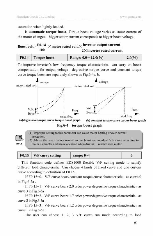
61
saturation when lightly loaded.1: automatic torque boost. Torque boost voltage varies as stator current of
the motor changes bigger stator current corresponds to bigger boost voltage.
Boost volt.= motor rated volt.
To improve inverter’s low frequency torque characteristic can carry on boost compensation for output voltage degressive torque curve and constant torque curve torque boost are separately shown as Fig.6-4a, b.
Fig.6-4 torque boost graph
This function code defines EDS1000 flexible V/F setting mode to satisfy different load characteristic. Can choose 4 kinds of fixed curve and one custom curve according to definition of F0.15.
If F0.15=0 V/F curve bears constant torque curve characteristic as curve 0 in Fig.6-5a .
If F0.15=1 V/F curve bears 2.0 order power degressive torque characteristic as curve 3 in Fig.6-5a .
If F0.15=2 V/F curve bears 1.7 order power degressive torque characteristic as curve 2 in Fig.6-5a .
If F0.15=3 V/F curve bears 1.2 order power degressive torque characteristic as curve 1 in Fig.6-5a .
The user can choose 1, 2, 3 V/F curve run mode according to load
F0.15 V/F curve setting range: 0~4 0
F0.14 Torque boost Range: 0.0 12.0(%) 2.0(%)
inverter output current 2 inverter rated current
(a)degressive torque curve torque boost graph (b) constant torque curve torque boost graph
motor rated volt.
Volt. Boost
voltage
rated freq.
Freq. Volt. Boost
rated freq.
Freq.
motor rated volt. voltage
100F0.14
(1) Improper setting to this parameter can cause motor heating or over current protection.
(2) Advise the user to adopt manual torque boost and to adjust V/F curve according to motor parameter and usage occasion when driving synchronous motor.note
Shenzhen Gozuk Co., Limited www.gozuk.com---------------------------------------------------------------------------------------------------------------------------

62
characteristic to reach better energy save result while the inverter is driving degressive torque load such as blower and water pump etc..
If F0.15=4, you can set V/F curve yourself by setting F2.37-F2.44 parameters.
As shown in Fig.6-5b, by setting three inflexion point (V1,F1), (V2,F2), (V3,F3), you can define V/F curve arbitrarily to apply to special load.
Fig.6-5a V/F curve b Users set the general form of V/F curve
0: G type 1: P type
6.2 Start, stop, braking function parameter group: F1
0: start from starting frequency. The inverter start according to F1.01 starting frequency and F1.02 starting frequency holding time.
1: first brake then start from starting freq. First brake according to DCbraking voltage and time (F1.03, F1.04) then start at starting frequency.
2: Start after inspecting speed.
F1.00 Start run mode range: 0, 1, 2 0
F0.16 G/P type setting range: 0, 1 0
rated freq.
Rated volt.
0
0 12
3
Output freq. Hz
Output volt. Voltage %
Frequency Hz
F1 F2 F3 Fb
V1
V2V3
100%
V1~V3 The 1th-3th voltage percentage of VF multi section
F1~F3 The1th-3th of multi section VF frequency points
Fb Setting frequency
(1) Start-up mode 0: Advise the user to adopt start-up mode 0 in common application occasion and when driving synchronous motor.
(2) Start-up mode 1: Be applicable to small inertia load with forward run or reverse run phenomena when the motor doesn’t drive any device, for big inertia load, advise not to adopt start-up mode 1.
(3) Start up mode2: Be application for big inertia load haven’t firm stopped start, usually cooperate with restart after power lost, fault recovery function and so on. Please notice the following two points before use the start. A. Wait few seconds to restart after inverter free stop. If turn out over current fault in
start process, please extend restart time. B. Don’t revise frequency in speed check process, otherwise it will alarm.
note
Shenzhen Gozuk Co., Limited www.gozuk.com---------------------------------------------------------------------------------------------------------------------------
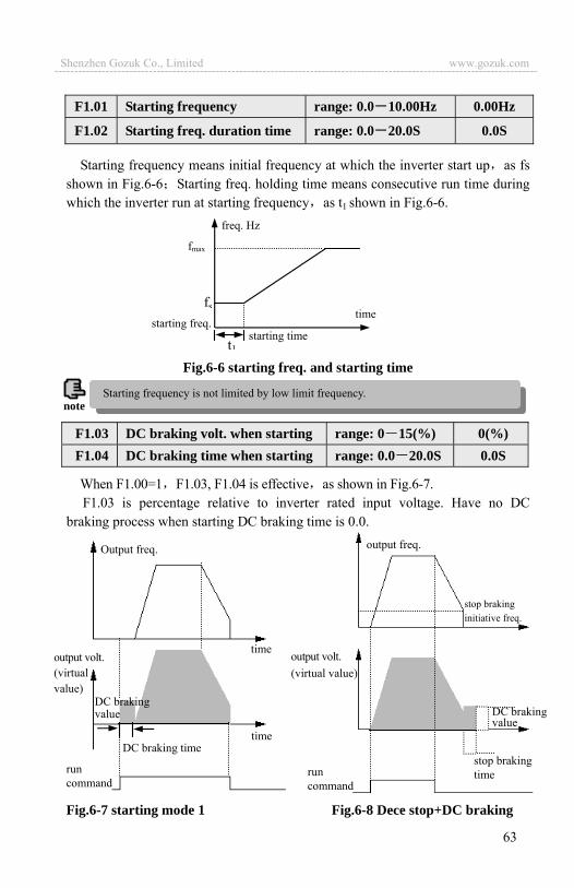
63
Starting frequency means initial frequency at which the inverter start up as fs shown in Fig.6-6 Starting freq. holding time means consecutive run time during which the inverter run at starting frequency as t1 shown in Fig.6-6.
Fig.6-6 starting freq. and starting time
When F1.00=1 F1.03, F1.04 is effective as shown in Fig.6-7. F1.03 is percentage relative to inverter rated input voltage. Have no DC
braking process when starting DC braking time is 0.0.
Fig.6-7 starting mode 1 Fig.6-8 Dece stop+DC braking
F1.03 DC braking volt. when starting range: 0 15(%) 0(%) F1.04 DC braking time when starting range: 0.0 20.0S 0.0S
output freq.
DC braking value
stop braking time run
command
output volt. (virtual value)
stop braking initiative freq.
F1.01 Starting frequency range: 0.0 10.00Hz 0.00Hz
F1.02 Starting freq. duration time range: 0.0 20.0S 0.0S
Starting frequency is not limited by low limit frequency. note
starting timestarting freq.
time
t1
fs
fmax
freq. Hz
output volt. (virtual value)
time
time DC braking time
run command
DC braking value
Output freq.
Shenzhen Gozuk Co., Limited www.gozuk.com---------------------------------------------------------------------------------------------------------------------------

64
0: Dece stop. The inverter reduces output frequency gradually according to set Dece time upon receival of stop command and stops running after frequency is reduced to 0.
1: free stop. The inverter stop outputting at once when receiving stop command and the load stops freely according to mechanical inertia.
2: Dec plus DC braking stop. The inverter reduces output frequency gradually according to set Dece time upon receival of stop command and start DC braking when F1.06 stop braking initiative frequency is reached.
F1.08 is percentage relative to inverter rated input voltage. Have no DC braking process if stop braking time is 0.0s as shown in Fig.6-8.
6.3 Auxiliary run function parameter group: F2
The time constant used when the inverter filter sampled value when frequency is set by exterior analog channel. Can improve the situation by increasing this filtering time constant if connecting wire is long or disturbance is serious which cause unstable set frequency.
Analog filtering time constant must be bigger than F3.11(sampling cycle), otherwise the system would run unsteadily.
During process of transiting from
forward run to reverse run or from
reverse run to forward run, transition
time during which the inverter wait at zero output frequency, as t1 shown in
Fig.6-9.
F1.05 Stop mode Range: 0, 1, 2 0
F1.06 DC braking initiative frequency when stop
range: 0.0 15.00Hz 3.00Hz
F1.07 DC braking time when stop range: 0.0 20.0S 0.0S
F1.08 DC braking voltage when stop range: 0 15(%) 0
F2.01 FWD REV run dead-section time range: 0.0 3600.0S 0.1S
F2.00 Analog filter time constant range: 0.00 30.00S 0.20S
F2.02 Automatic energy save run range: 0, 1 0
Fig.6-9 FWD REV run dead-section time
time
t1
Output frequency
Shenzhen Gozuk Co., Limited www.gozuk.com---------------------------------------------------------------------------------------------------------------------------

65
To reach better energy save result, the inverter would detect load current to get the purpose of automatic energy save.
0: no action 1: action
Empty or lightly loaded motor can get the purpose of energy save by detecting load current to adjust output voltage properly. Automatic energy save run is mainly applied to occasion of stable load, speed.
AVR namely automatic voltage adjusting function. Indicate that the inverter can output constant voltage by AVR function when the inverter input voltage fluctuates.
0: no action 1: action all the time 2: no action only during Dece
This function can adjust output frequency properly as the load varies to compensate slip frequency of the asynchronous motor dynamically, so that control motor speed in constant value. If act with automatic torque boost function, can get better low speed moment characteristic. As shown in Fig.6-10.
F2.03 AVR function range: 0, 1, 2 0
F2.05 Carrier wave freq. range: 2 15.0K Depend on device type
Output current 100% Slip compensation
After slip
compensation
Motor speed
Before slip compensation
150%
100%
50%
Fig.6-10 slip freq. compensation graph
note This function commonly applied to load such as blower and water pump etc.
(1) when input voltage is higher than rated value, under normal situation should set F2.03=1. When F1.05=0 namely inverter in decelerating stop motor Dec time is short and running current would be bigger. But the motor decrease speed placidly with small run current and long Dec time if choose AVR action all the time.
(2) should set F2.03=0, namely AVR function ineffective when the motor systemoscillates which caused by choosing AVR function.
note
F2.04 Slip freq. compensation range:0~150% 0
Shenzhen Gozuk Co., Limited www.gozuk.com---------------------------------------------------------------------------------------------------------------------------

66
Carrier frequency mainly affects motor noise and heat consumption during running. Relation between carrier frequency and motor noise, current leakage, disturbance is as follows:
Carrier frequency increase( ) motor noise decrease( ) motor current leakage increase( ) disturbance to environment increase( )
Carrier frequency decrease ( ) motor noise increase ( ) motor current leakage decrease ( ) disturbance to environment decrease ( )
Should decrease carrier frequency properly to reduce heat consumption of the inverter when ambient temperature is high and motor load is heavy. Relation of EDS1000 each type and carrier frequency is as shown in Table 6-1.
Table 6-1 Relation table of device type and carrier frequency Max.carrier freq.
(KHz) Min. carrier freq
(KHz) factory default
(KHz) 0.4KW 15 2.0 2
0.75KW 14 2.0 2 1.5KW 13 2.0 2 2.2KW 12 2.0 2 3.7KW 12 2.0 2 5.5KW 11 2.0 2 7.5KW 10 2.0 2 11KW 11.0 0.7 2 15KW 10.0 0.7 2
18.5KW 9.0 0.7 2 22KW 8.0 0.7 2 30KW 7.5 0.7 2 37KW 7.0 0.7 2 45KW 6.0 0.7 2 55KW 5.5 0.7 2
Jog frequency has the highest priority. Under any status, the inverter would transit to run at jog frequency at once according to set jog accelerating, decelerating time as long as jog command is inputted, as shown in Fig.6-11.
F2.06 Jog run frequency range: 0.10 50.00Hz 5.00Hz
F2.07 Jog Acce time range: 0.1 60.0S 20.0SF2.08 Jog Dece time range: 0.1 60.0S 20.0S
carrier freq. device type
note
(1) To get better control characteristic suggest that the ratio of carrier frequency to inverter max. run frequency be not smaller than 36.
(2) Error exists in current displayed value when carrier frequency is small.
Shenzhen Gozuk Co., Limited www.gozuk.com---------------------------------------------------------------------------------------------------------------------------

67
Jog accelerating time means time during which the inverter accelerate from 0Hz to high limit frequency Jog Dec time means time during which the inverter decelerate from high limit frequency to 0Hz.
0: VCI CCI 1: VCI CCI 2: YCI CCI
YCI specified frequency is positive or negative. Here YCI input 0 10V corresponds to frequency -50.00Hz~+50.00Hz 0~5V corresponds to frequency -50.00 0Hz 5~10V corresponds to 0~+50.00Hz.
3: RS485+YCI When you choose RS485+YCI YCI input voltage 0~5V—YCI dead band
(F7.12) corresponds to -50.00Hz—0.00Hz 5V—YCI dead band (F7.12) YCI5V+YCI dead band (F7.12) corresponds to 0Hz YCI>5V+YCI dead band (F7.12) corresponds to 0.00~+50.00Hz. You can carry out tension control by this function.
4: VCI YCI 5: reserved 6: external pulse provision CCI7: external pulse provision CCI 8: reserved 9: reserved 10: reserved 11: reserved12: reserved
Fig.6-11 jog run
Jogfreq.
Jogaccelerating time
Jog decelerating time
Jog signal
Jogfreq.
Jog signal
F2.09 Freq. input channel combination range: 0 28 0
(1) Keypad, control terminal and serial port can do jog control all. (2) The inverter will stop according to Dec stop mode after jog run command is withdrawn.
note
Shenzhen Gozuk Co., Limited www.gozuk.com---------------------------------------------------------------------------------------------------------------------------

68
13: VCI CCI any nonzero value effective VCI preferred 14: reserved 15: RS485+CCI 16: RS485-CCI 17: RS485+VCI 18: RS485-VCI 19: RS485+keypad analog potentiometer 20: RS485- keypad analog potentiometer 21: VCI+ keypad analog potentiometer 22: VCI- keypad analog potentiometer 23: CCI+ keypad analog potentiometer 24: CCI- keypad analog potentiometer 25: reserved 26: reserved 27: reserved 28: reserved
Main&sub inverter communication freq. provision proportion this parameter need to be set in sub inverter but not need in main inverter.
F2.11 make use of 4 bits of the parameter to set if C-07—C-10 is displayed in parameter, thereinto 0 indicates not displayed, 1 indicates displayed. Set parameter of 4 bit is as following figure:
Remark: accu. is abbreviation of accumulative.
F2.11 LED display control 1 range: 0000-1111 0000
F2.12 LED display control 2 range: 0000-1111 1111
C-07: run time
C-08: accu. run time
C-09: input end status
C-10: output end status
4th bit 3rd bit 2nd bit 1st bit
F2.10 main&sub inverter communication freq. provision proportion
range: 0 500(%)
100(%)
Shenzhen Gozuk Co., Limited www.gozuk.com---------------------------------------------------------------------------------------------------------------------------
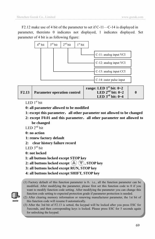
69
F2.12 make use of 4 bit of the parameter to set if C-11—C-14 is displayed in parameter, thereinto 0 indicates not displayed, 1 indicates displayed. Set parameter of 4 bit is as following figure:
LED 1st bit 0: all parameter allowed to be modified 1: except this parameter all other parameter not allowed to be changed 2: except F0.01 and this parameter all other parameter not allowed to
be changed LED 2nd bit 0: no action 1: renew factory default 2: clear history failure record LED 3rd bit 0: not locked 1: all buttons locked except STOP key 2: all buttons locked except , STOP key 3: all buttons locked except RUN, STOP key 4: all buttons locked except SHIFT, STOP key
F2.13 Parameter operation controlrange: LED 1st bit: 0~2
LED 2nd bit: 0~2 LED 3rd bit: 0~4
0
C-11: analog input VCI
C-12: analog input YCI
C-13: analog input CCI
C-14: outer pulse input
4th bit 3rd bit 2nd bit 1st bit
(1) Factory default of this function parameter is 0 i.e., all the function parameter can be modified. After modifying the parameter, please first set this function code to 0 if you want to modify function code setting. After modifying the parameter you can change this function code setting to expected protection grade if parameter protection is needed.
(2) After clearing memory information or renewing manufacturer parameter, the 1st bit of this function code will resume 0 automatically.
(3) After the 3rd bit of F2.13 is setted, the keypad will be locked after you press ESC for 5seconds, and then corresponding keys is locked. Please press ESC for 5 seconds again for unlocking the keypad.
note
Shenzhen Gozuk Co., Limited www.gozuk.com---------------------------------------------------------------------------------------------------------------------------
70
F2.14 make use of 1st bit, 2nd bit to set baud rate and data format of serial communication thereinto LED 1st bit represents communication baud rate, set value as follows:
0: 1200BPS 1: 2400BPS 2: 4800BPS 3: 9600BPS 4: 19200BPS 5: 38400BPS LED 2nd bit: represents data format set value as follows: 0: 1 8 1 format, no checkout. Namely: 1 bit for starting, 8 bits for data,
1 bit for stop, no checkout.1: 1 8 1 format even checkout. Namely: 1 bit for starting, 8 bits for data,
1 bit for stop, even checkout.2: 1 8 1 format odd checkout. Namely: 1 bit for starting, 8 bits for data,
1 bit for stop, odd checkout.
This function code is used to identify address of this inverter during serial port communication.127 is for main inverter during main and sub device communication between inverters.
When serial port communication fails and its continuous time exceed set value of this function code the inverter judge it as communication failure. The inverter would not detect serial port communication signal, namely this function ineffective when set value is 0.
Local response delay time represents the time within which the inverter serial port receive and execute command from upper device and then respond to upper device this function is just used for setting this delay time.
F2.15 Local address range: 0 127 127 is broadcast address 1
F2.16 Communication overtime checkout time range: 0.0 1000.0S 0.0S
F2.17 Local response delay time range: 0 200ms 5ms
F2.14 communication configuration range: LED 1st bit: 0~5 LED 2nd bit: 0, 1, 2
03
127 is broadcast address can only receive and execute broadcast command from upper machine but not respond to upper machine when 127 is set to broadcast address.!
Shenzhen Gozuk Co., Limited www.gozuk.com---------------------------------------------------------------------------------------------------------------------------
71
Can define 3 kinds of accelerating decelerating time and can choose accelerating decelerating time 1 7 during inverter run process by different combination of control terminal please see definition for function of accelerating decelerating time terminal in F5.00 F5.07.
These set frequency will be used in multi-step speed run mode and simple PLC run mode please refer to multi-step speed run terminal function of F5.00 F5.07and F4 group simple PLC function.
F2.30 Multi-step freq. 1 range: low limit high limit 5.00Hz
F2.31 Multi-step freq. 2 range: low limit high limit 10.00Hz
F2.32 Multi-step freq. 3 range: low limit high limit 20.00Hz
F2.33 Multi-step freq. 4 range: low limit high limit 30.00Hz
F2.34 Multi-step freq. 5 range: low limit high limit 40.00Hz
F2.35 Multi-step freq. 6 range: low limit high limit 45.00Hz
F2.36 Multi-step freq. 7 range: low limit high limit 50.00Hz
F2.18 Acce time 2 range: 0.1 6000.0 20.0
F2.19 Dece time 2 range: 0.1 6000.0 20.0
F2.20 Acce time 3 range: 0.1 6000.0 20.0
F2.21 Dece time 3 range: 0.1 6000.0 20.0
F2.22 Acce time 4 range: 0.1 6000.0 20.0
F2.23 Dece time 4 range: 0.1 6000.0 20.0
F2.24 Acce time 5 range: 0.1 6000.0 20.0
F2.25 Dece time 5 range: 0.1 6000.0 20.0
F2.26 Acce time 6 range: 0.1 6000.0 20.0
F2.27 Dece time 6 range: 0.1 6000.0 20.0
F2.28 Acce time 7 range: 0.1 6000.0 20.0
F2.29 Dece time 7 range: 0.1 6000.0 20.0
Accelerating decelerating time 1 is defined in F0.08 and F0.09. note
Shenzhen Gozuk Co., Limited www.gozuk.com---------------------------------------------------------------------------------------------------------------------------
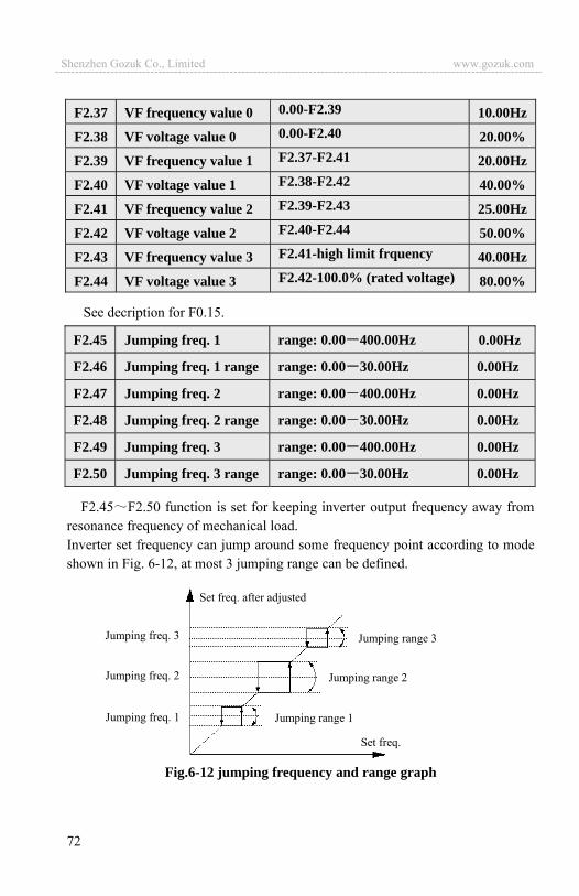
72
See decription for F0.15.
F2.45 F2.50 function is set for keeping inverter output frequency away from resonance frequency of mechanical load. Inverter set frequency can jump around some frequency point according to mode shown in Fig. 6-12, at most 3 jumping range can be defined.
Fig.6-12 jumping frequency and range graph
Jumping range 3
Jumping freq. 1
Jumping freq. 2
Jumping freq. 3
Set freq. after adjusted
Jumping range 2
Jumping range 1
Set freq.
F2.45 Jumping freq. 1 range: 0.00 400.00Hz 0.00Hz
F2.46 Jumping freq. 1 range range: 0.00 30.00Hz 0.00Hz
F2.47 Jumping freq. 2 range: 0.00 400.00Hz 0.00Hz
F2.48 Jumping freq. 2 range range: 0.00 30.00Hz 0.00Hz
F2.49 Jumping freq. 3 range: 0.00 400.00Hz 0.00Hz
F2.50 Jumping freq. 3 range range: 0.00 30.00Hz 0.00Hz
F2.37 VF frequency value 0 0.00-F2.39 10.00Hz
F2.38 VF voltage value 0 0.00-F2.40 20.00%
F2.39 VF frequency value 1 F2.37-F2.41 20.00Hz
F2.40 VF voltage value 1 F2.38-F2.42 40.00%
F2.41 VF frequency value 2 F2.39-F2.43 25.00Hz
F2.42 VF voltage value 2 F2.40-F2.44 50.00%
F2.43 VF frequency value 3 F2.41-high limit frquency 40.00Hz
F2.44 VF voltage value 3 F2.42-100.0% (rated voltage) 80.00%
Shenzhen Gozuk Co., Limited www.gozuk.com---------------------------------------------------------------------------------------------------------------------------
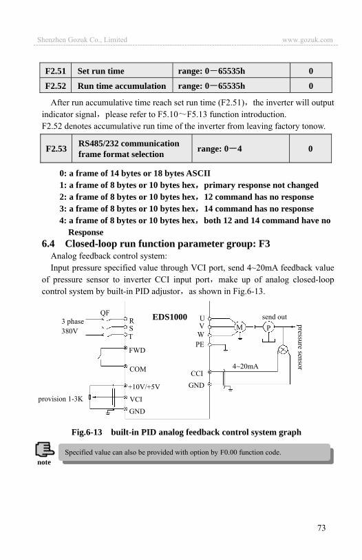
73
After run accumulative time reach set run time (F2.51) the inverter will output indicator signal please refer to F5.10 F5.13 function introduction. F2.52 denotes accumulative run time of the inverter from leaving factory tonow.
0: a frame of 14 bytes or 18 bytes ASCII 1: a frame of 8 bytes or 10 bytes hex primary response not changed 2: a frame of 8 bytes or 10 bytes hex 12 command has no response 3: a frame of 8 bytes or 10 bytes hex 14 command has no response 4: a frame of 8 bytes or 10 bytes hex both 12 and 14 command have no
Response 6.4 Closed-loop run function parameter group: F3
Analog feedback control system: Input pressure specified value through VCI port, send 4~20mA feedback value
of pressure sensor to inverter CCI input port make up of analog closed-loop control system by built-in PID adjustor as shown in Fig.6-13.
F2.51 Set run time range: 0 65535h 0
F2.52 Run time accumulation range: 0 65535h 0
F2.53 RS485/232 communication frame format selection range: 0 4 0
FWD
COM
GND VCI
+10V/+5V GNDCCI
provision 1-3K
M PUVWPE
3 phase 380V
QF EDS1000 send outRST
4~20mA
Fig.6-13 built-in PID analog feedback control system graph
Specified value can also be provided with option by F0.00 function code.note
Shenzhen Gozuk Co., Limited www.gozuk.com---------------------------------------------------------------------------------------------------------------------------
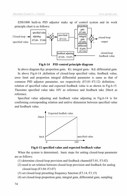
74
EDS1000 built-in PID adjustor make up of control system and its work principle chart is as follows:
Fig.6-14 PID control principle diagramIn above diagram Kp: proportion gain Ki: integral gain Kd: differential gain In above Fig.6-14 ,definition of closed-loop specified value, feedback value,
error limit and proportion integral differential parameter is same as that of common PID adjustor parameter, see respectively (F3.01~F3.12) definitionrelation of specified value and expected feedback value is as shown in Fig.6-15. Thereinto specified value take 10V as reference and feedback take 20mA as reference.
Specified value adjusting and feedback value adjusting in Fig.6-14 is for confirming corresponding relation and unitive dimension between specified value and feedback value.
Fig.6-15 specified value and expected feedback value When the system is determined basic steps for setting closed-loop parameter
are as follows: (1) determine closed-loop provision and feedback channel(F3.01, F3.02) (2) need to set relation between closed-loop provision and feedback for analog
closed-loop (F3.04~F3.07) (3) set closed-loop presetting frequency function (F3.14, F3.15) (4) set closed-loop proportion gain, integral gain, differential gain, sampling
specified value
Expected feedbck value 20mA
4mA
10V0
Closed-loop
specified value
feedback adjusting(F3.05 F3.07)
error limit (F3.12)
closed-loop feedback value
+
_integral
gain (F3.09)
proportion gain
(F3.08)
closed-loopoutput+
+
differenti-al gain (F3.10)
specified value adjusting
(F3.04 F3.06)
Shenzhen Gozuk Co., Limited www.gozuk.com---------------------------------------------------------------------------------------------------------------------------

75
cycle, error limit (F3.08~F3.12)
0: closed-loop run control ineffective 1: PID closed-loop run control effective 2: constant pressure water supply PID control effective
This parameter is mainly used for implementing one-driving-two water supply function. If need one driving three or one driving four, please choose a dedicated water supply substrates to achiveve.
0: digital provision. 1: VCI analog 0 10V voltage provision 2: CCI analog provision. Can choose 0~10V voltage or 4~20mA current
provision3: keypad analog potentiometer provision
0: VCI analog input voltage 0 10V 1: CCI analog input 2: VCI+CCI 3: VCI-CCI 4: Min { VCI, CCI }5: Max { VCI, CCI }
When CCI analog input is selected to be current input, it will be converted to voltage value in the inverter.
6: pulse feedback
When F3.00=1, figure given value F3.03 will be as specified value of closed-loop control system directly. At this time please setF3.21to 9.999(v);
When F3.00=2, Start PID control constant pressure water supply, At this point the water supply system F3.03 will become the target pressure value. Upper limit is F3.21Mpa.
F3.00 Closed-loop run control selection range: 0, 1, 2 0
F3.02 Feedback channel selection range: 0~6 1
F3.03
Specified value digital setting range: 0.00 9.999V 1.000V
Target pressure value setting Range:0.00 F3.21Mpa 1.000(Mpa)
Besides setting F3 group of related closed loop running parameters, F5.10 F5.13 OC1 OC4 must be set to 21.!
F3.01 provision channel selection range: 0~3 1
Shenzhen Gozuk Co., Limited www.gozuk.com---------------------------------------------------------------------------------------------------------------------------
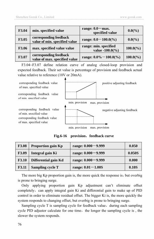
76
F3.04~F3.07 define relation curve of analog closed-loop provision and expected feedback. Their set value is percentage of provision and feedback actual value relative to reference (10V or 20mA).
The more big Kp proportion gain is, the more quick the response is but overbig is prone to bringing surge.
Only applying proportion gain Kp adjustment can’t eliminate offset completely can apply integral gain Ki and differential gain to make up of PID control in order to eliminate residual offset. The bigger Ki is, the more quickly the system responds to changing offset, but overbig is prone to bringing surge.
Sampling cycle T is sampling cycle for feedback value during each sampling cycle PID adjustor calculate for one time the longer the sampling cycle is , the slower the system responds.
F3.04 min. specified value range: 0.0 max. specified value 0.0(%)
F3.05 corresponding feedback value of min. specified value range: 0.0 100.0(%) 0.0(%)
F3.06 max. specified value value range: min. specified value -100.0(%) 100.0(%)
F3.07 corresponding feedback value of max. specified value range: 0.0% 100.0(%) 100.0(%)
F3.08 Proportion gain Kp range: 0.000 9.999 0.050
F3.09 Integral gain Ki range: 0.000 9.999 0.050S
F3.10 Differential gain Kd range: 0.000 9.999 0.000
F3.11 Sampling cycle T range: 0.01 1.00S 0.10S
Fig.6-16 provision feedback curve
positive adjusting feedback corresponding feedback value of max. specified value
corresponding feedback value of min. specified value
max. provisionmin. provision
corresponding feedback value of min. specified value corresponding feedback value of max. specified value
negative adjusting feedback
max. provisionmin. provision
Shenzhen Gozuk Co., Limited www.gozuk.com---------------------------------------------------------------------------------------------------------------------------

77
For Max. offset of closed-loop specified value as shown in Fig.6-17 PID
adjustor stops adjusting when feedback value is within this range. To utilize this function reasonably redound to harmonizing the conflict between system output precision and stabilization.
PID integral separation integral don’t react when specified value and feedback value are bigger than this limit only when specified value and feedback value are smaller than or equal to this limit integral react. Can adjust system response speed by adjusting this parameter.
This function can make closed-loop adjusting enter into stable phase quickly. After closed-loop run starts, the inverter first accelerates to preset frequency F3.14 in terms of accelerating time and after running at this frequency for a period of time F3.15, it runs according to closed-loop characteristic. As shown in Fig.6-18.
The function of sleep frequency threshold: When the system water pressure in
F3.12 Deviation limit range: 0.0 20.0(%) 2.0(%)
F3.16 Sleep frequency threshold range: 0.00 400.00Hz 30.00Hz
F3.17 Wake pressure threshold range: 0.00 F3.21Mpa 0.500Mpa
preset freq.
time T
preset freq. holding time
output freq. offsetlimit
time
time
Output Freq.
specified value
Feedback value
F3.13 Integral separation PID adjusting threshold range: 0.0 100.0% 100.0
F3.14 Closed-loop preset frequency range: 0-high limit freq. 0.00Hz
F3.15 Closed-loop preset frequency holding time range: 0.0-6000S 0.0S
Fig.6-17 offset limit Fig.6-18 closed-loop preset freq.
Set preset freq. and holding time to “0’ if closed-loop preset freq. function is not needed.note
Shenzhen Gozuk Co., Limited www.gozuk.com---------------------------------------------------------------------------------------------------------------------------
78
the scope of F3.12 (deviation limit), and the inverter operating frequency is under the F3.16 (sleep frequency), after the F3.18 (sleep delay time), the inverter will enter a sleep state, operating frequency will drop to 0.00HZ in order to save energy conservation and protect motor.
Wake function: When the system is in sleep mode, When the water feedback pressure is less than F3.17 (wake pressure ). At this time the inverter had passed F3.19(Delayed recovery time) , Sleep out.
This parameter is to set delay time when entering into sleep function. Inverter will enter the delay time of sleep state. When the system pressure at this delay time does not meet the conditions of sleep, System does not enter the sleepin mode.
System in sleep mode, if the feedback pressure of system less than F3. 17 wake pressure threshold value , the system will out of sleep after this delay time.
0: inverter works in one-drive-two water supply mode 1: constant pressure water supply board acts in one-drive-two mode 2: constant pressure water supply board acts in one-drive-three mode 3: constant pressure water supply board acts in one-drive-four mode
To set this parameter correspondingly to 10V or 20mA.
By this parameter, we defines that the inverter begins to add or reduce pumps when output frequency falls in offset range of high limit frequency or lower limit frequency. The inverter begins to add or reduce pumps at high limit frequency or lower limit frequency if this parameter is set to be 0.0%.
This parameter defines the judging time from output frequency up to high limit to adding pump and the same from ouput frequency up to lower limit to reducing pump.
F3.19 Revival delay time range: 0.0 6000.0S 0.0
F3.20 Constant pressure water supply mode 1 range: 0~3 0
F3.23 Pump switchover judging time range: 0.0 999.9S 5.0
F3.18 Sleep delay time range: 0.0 6000.0S 0.0
F3.21 Long-distance manometer range range: 0.001 9.999 1.000
F3.22 Allowed offset to high limit and lower limit Freq. when add or reduce pumps
range: 0.0 100.0%
1.0
F3.24 Magnetic control conductor switchover delay time range: 0.1 10.0S 0.5
Shenzhen Gozuk Co., Limited www.gozuk.com---------------------------------------------------------------------------------------------------------------------------

79
This parameter defines the action delay time of magnetic control conductor when it’s from power source to variable frequency or from variable frequency to power source.
By setting this parameter, can achieve the function of rust-proof die of the motor, the inverter can delay time by it and then automatically smart switch run pumps and static pump. When setting value is 0000 minutes, the automatic switching is invalid; when setting value is 0001,the system will automatically switch one time in each restarted time. when work it would’t switch: when setting value is above 0002,the system will automatically switch by setting value.
0: C-11, C-12 display voltage value of VCI, CCI. 1: C-11, C-12 display PID specified pressure and feedback pressure.
0: Forward function. motor speed increases as specified value increases. 1: Reverse function. motor speed decreases as specified value increases.
This parameter defines initial supervision parameter selection during running or stop. For example F3.28=3, LED displays output voltage initially, please press SHIFT key if you want to see about other supervision parameter.
0: set frequency: Standby mode display set the frequency, output frequency is displayed after running.
1: output frequency: Display output frequency not only standby but also running .
2: output current 3: output voltage 4: DC bus bar voltage 5: motor speed 6: heat sink temperature 7: run time 8: accumulative run time 9: input terminal status 10: output terminal status 11: analog input VCI/PID provision
F3.27 Closed-loop adjusting characteristic range: 0, 1 0
F3.25 Automatic switchover interval range: 0000 9999 0000
F3.26 Water supply supervision Para. display range: 0, 1 0
F3.28 LED initial supervision Para. selection range: 0~14 1
Shenzhen Gozuk Co., Limited www.gozuk.com---------------------------------------------------------------------------------------------------------------------------
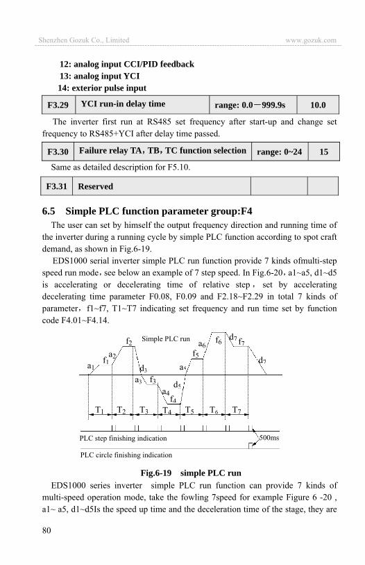
80
12: analog input CCI/PID feedback 13: analog input YCI 14: exterior pulse input
The inverter first run at RS485 set frequency after start-up and change set frequency to RS485+YCI after delay time passed.
Same as detailed description for F5.10.
6.5 Simple PLC function parameter group:F4 The user can set by himself the output frequency direction and running time of
the inverter during a running cycle by simple PLC function according to spot craft demand, as shown in Fig.6-19.
EDS1000 serial inverter simple PLC run function provide 7 kinds ofmulti-step speed run mode see below an example of 7 step speed. In Fig.6-20 a1~a5, d1~d5 is accelerating or decelerating time of relative step set by accelerating decelerating time parameter F0.08, F0.09 and F2.18~F2.29 in total 7 kinds of parameter f1~f7, T1~T7 indicating set frequency and run time set by function code F4.01~F4.14.
Fig.6-19 simple PLC run EDS1000 series inverter simple PLC run function can provide 7 kinds of
multi-speed operation mode, take the fowling 7speed for example Figure 6 -20 , a1~ a5, d1~d5Is the speed up time and the deceleration time of the stage, they are
F3.29 YCI run-in delay time range: 0.0 999.9s 10.0
F3.30 Failure relay TA TB TC function selection range: 0~24 15
F3.31 Reserved
a1f1
a2
f2
d3
a3 f3
T1
a4f4
d5
a5
f5a6
f6d7 f7
d7
T2 T3 T4 T5 T6 T7
500ms PLC step finishing indication
PLC circle finishing indication
Simple PLC run
Shenzhen Gozuk Co., Limited www.gozuk.com---------------------------------------------------------------------------------------------------------------------------

81
setted by the acceleration time parameters F 0.08,F0.09and F2.18~F2.29, a total of seven kinds of parameters, the run frequency and run time of f1~ f7, T1~ T7 are setted by function code F4.01~f4.14.
Fig.6-20 stop after PLC single circlePLC step finishing and circle finishing indication can be realized by outputting
500mS pulse indicator signal through open circuit collector terminal OC1~OC4detailed function defined by F5.10~F5.13.
This function code make use of its 1st bit, 2nd bit, 3rd bit to set PLC run mode, PLC rerun mode after interruption set run time unit detail as follows:
LED 1st:0: no action. PLC run mode ineffective. 1: stop after single circulation. As shown in Fig.6-20 the inverter stops
automatically after finishing a circle can only start when another run command is available.
2: keep final value after single circulation. As shown in Fig.6-21 the inverter keep running according to frequency, direction of final step after finishing a circle the inverter won’t stop according to set decelerating time until the stop command is available.
F4.00 Simple PLC running setting
range: LED 1st bit: 0~3 LED 2nd bit: 0, 1 LED 3rd bit :0, 1 000
T1 T2 T3 T4 T5 T6 T7
a1f1
a2
f2
d3a3 f3
a4f4
d5
a5
f5
f6d7 f7
d7
Simple PLC run a6
RUN command
Shenzhen Gozuk Co., Limited www.gozuk.com---------------------------------------------------------------------------------------------------------------------------

82
3: consecutive circulation. As shown in Fig.6-22 the inverter start next circle automatically after finishing a circle until there is stop command.
LED 2nd bit: 0: start from first step. Stop during running caused by stop command,
failure or power off after restarting the inverter will run from first step. 1: continue to run from step frequency of interruption moment. When
stop during running caused by stop command or failure the inverter will record current step used time automatically and enter into this step automatically after restarting continue to run for residual time according to defined frequency of this step, as shown in Fig.6-23. The inverter will rerun from first step after restarting if power off.
Fig.6-21 holding mode after PLC single circle
f2 a6f6 d7f7
T1 T2 T3 T4 T5 T6 T7
a1f1
a2d3
a3 f3a4
f4
d5
a5
f5 d7
RUN command
STOP command
Fig.6-22 PLC consecutive circle modeSTOP
f6
RUN command
First circle Second circleT1 T2 T3 T4 T5 T6 T7 T1 T2 T3 T4 T5 T6 T7 T1
f1
d1
d1d2PLC run
f2
f3
f4
f5
f7
f1
f2
f3
f4
f5
f6
f7
f1
Shenzhen Gozuk Co., Limited www.gozuk.com---------------------------------------------------------------------------------------------------------------------------

83
Fig.6-23 PLC starting mode 1LED 3rd bit : PLC run time unit 0: second 1: minute
This unit is only effective to PLC run step time for accelerating decelerating time of PLC run period, their unit selection is determined by F0.07.
output freq.Hz
Interruption signal
a1: step 1 accelerating time a2: step 2 accelerating time a3: step 3 accelerating time d2: step 2 decelerating time f1: step 1 frequency f2: step 2 frequency f3: step 3 frequency
a1
f1d2
a2
f2a3
f3
Step 1 Step 2
Used time Step 2 residual time
Time t
(1) If run time of PLC segment is set to 0 this segment is ineffective. (2) can make PLC process a pause, ineffective, work etc. through terminal for detail please refer to terminal correlative function parameter group F5.note
F4.01 Section 1 setting range: 000 621 000F4.02 Section 1 runtime range: 0 6000.0 10.0 F4.03 Section 2 setting range: 000 621 000F4.04 Section 2 runtime range: 0 6000.0 10.0 F4.05 Section 3 setting range: 000 621 000F4.06 Section 3 runtime range: 0 6000.0 10.0 F4.07 Section 4 setting range: 000 621 000F4.08 Section 4 runtime range: 0 6000.0 10.0 F4.09 Section 5 setting range: 000 621 000F4.10 Section 5 runtime range: 0 6000.0 10.0 F4.11 Section 6 setting range: 000 621 000F4.12 Section 6 runtime range: 0 6000.0 10.0 F4.13 Section 7 setting range: 000 621 000F4.14 Section 7 runtime range: 0 6000.0 10.0
Shenzhen Gozuk Co., Limited www.gozuk.com---------------------------------------------------------------------------------------------------------------------------
84
F4.01~F4.14 utilize LED 1st bit, 2nd bit, 3rd bit to separately define frequency setting direction and accelerating decelerating time of PLC Run, see following for detail:
LED1st bit: frequency setting 0: multi-step frequency i i=1~7 is defined by F2.30~F2.44. 1: frequency is determined by function code F0.00 LED 2nd bit: run direction selection 0: forward run 1: reverse run 2: determined by run command (FWD,REV)LED3rd bit: accelerating decelerating time selection 0: accelerating decelerating time 1 1: accelerating decelerating time 2 2: accelerating decelerating time 3 3: accelerating decelerating time 4 4: accelerating decelerating time 5 5: accelerating decelerating time 6 6: accelerating decelerating time 7
6.6 Terminal correlative function parameter group: F5
Multi-function input terminal X1~X8 provides 43 kinds of selection mode for the user can choose based on spot requirement. For parameter function table please see Table 6-2.
F5.00 Input terminal X1 function selection range: 0~42 0
F5.01 Input terminal X2 function selection range: 0~42 0
F5.02 Input terminal X3 function selection range: 0~42 0
F5.03 Input terminal X4 function selection range: 0~42 0
F5.04 Input terminal X5 function selection range: 0~42 0
F5.05 Input terminal X6 function selection range: 0~42 0
F5.06 Input terminal X7 function selection range: 0~42 0
F5.07 Input terminal X8 function selection range: 0~42 0
Shenzhen Gozuk Co., Limited www.gozuk.com---------------------------------------------------------------------------------------------------------------------------

85
Table 6-2 multifunction input function selection table item corresponding function item corresponding function
0 Leave control terminal unused 1 Multi-step speed control terminal 1
2 Multi-step speed control terminal 2 3 Multi-step speed control terminal 3
4 Multi-step speed control terminal 4 5 External forward run jog control
6 External reverse run jog control 7 Acce/Dece time selecting terminal 1
8 Acce/Dece time selecting terminal 2 9 Acce/Dece time selecting terminal 3
10 External device failure input 11 External reset input
12 Free stop input 13 External stop command
14 stop DC braking input command DB 15 Inverter run prohibition
16 Frequency increasing control (UP) 17 frequency descending control(DOWN)
18 Acce/Dece prohibited command 19 Three-wire run control
20 Closed-loop ineffective 21 PLC ineffective
22 Simple PLC pause command 23PLC stop status reset (reset variable of PLC interruption moment, make it restart from first segment)
24 Frequency provision channel selection 1 25 Frequency provision channel selection 2
26 Frequency provision channel selection 3 27 Frequency switched to CCI
28 Command switched to terminal 29 Run command channel selection 1
30 Run command channel selection 2 31 Run command channel selection 3
32 Swing frequency jumpin 33 External interruption input
34 interior counter clearing end 35 interior counter triggering end
36 Interior timer clearing end 37 interior timer triggering end
38 Pulse frequency input(only effective for X7,X8) 39 Reserved
40 Reserved 41 Reserved
42 Reserved
Now explain listed function in Table 6-2 as follows: 1~4: Multi-step speed control terminal. Can set 15 step speed run
frequency by choosing ON/OFF combination of these function terminal.
Shenzhen Gozuk Co., Limited www.gozuk.com---------------------------------------------------------------------------------------------------------------------------
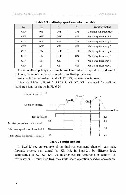
86
Multi-stepspeed control terminal 3
Multi-stepspeed control terminal 2
Multi-stepspeed control terminal 1
Output frequency
Common set freq.
Run command
Time
Speed1Speed2
Speed6Speed7
on
on
onK1
K2
K3
K4
Table 6-3 multi-step speed run selection table K4 K3 K2 K1 Frequency setting
OFF OFF OFF OFF Common run frequency
OFF OFF OFF ON Multi-step frequency 1
OFF OFF ON OFF Multi-step frequency 2
OFF OFF ON ON Multi-step frequency 3
OFF ON OFF OFF Multi-step frequency 4
OFF ON OFF ON Multi-step frequency 5
OFF ON ON OFF Multi-step frequency 6
OFF ON ON ON Multi-step frequency 7
Above multi-step frequency can be used in multi-step speed run and simple PLC run, please see below an example of multi-step speed run:
We now define control terminal X1, X2, X3, separately as follows: After set F5.00=1, F5.01=2, F5.03=3, X1, X2, X3, are used for realizing
multi-step run as shown in Fig.6-24.
Fig.6-24 multi-step run In fig.6-25 see an example of terminal run command channel can make
forward, reverse run control by K5, K6. In Fig.6-24, by different logic combination of K2, K3, K4 the inverter can run according to common set frequency or 1~7multi-step frequency multi-speed operation based on above table.
Shenzhen Gozuk Co., Limited www.gozuk.com---------------------------------------------------------------------------------------------------------------------------
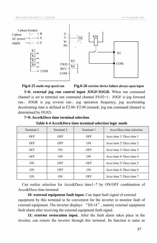
87
Fig.6-25 multi-step speed run Fig.6-26 exterior device failure always-open input
5~6: external jog run control input JOGF/JOGR. When run command channel is set to terminal run command channel F0.02=1 JOGF is jog forward run JOGR is jog reverse run jog operation frequency, jog accelerating decelerating time is defined in F2.06~F2.08 (remark: jog run command channel is determined by F0.02)
7~9: Acce&Dece time terminal selection Table 6-4 Acce&Dece time terminal selection logic mode
Can realize selection for Acce&Dece time1~7 by ON/OFF combination of Acce&Dece time terminal.
10: external equipment fault input. Can input fault signal of external equipment by this terminal to be convenient for the inverter to monitor fault of external equipment. The inverter displays E0.14 , namely external equipment fault alarm after receiving the external equipment fault signal.
11: exterior restoration input. After the fault alarm takes place in the inverter, can restore the inverter through this terminal. Its function is same as
Terminal 2 Terminal 2 Terminal 1 Acce/Dece time selection
OFF OFF OFF Acce time 1/ Dece time 1
OFF OFF ON Acce time 2/ Dece time 2
OFF ON OFF Acce time 3/ Dece time 3
OFF ON ON Acce time 4/ Dece time 4
ON OFF OFF Acce time 5/ Dece time 5
ON OFF ON Acce time 6/ Dece time 6
ON ON OFF Acce time 7/ Dece time 7
X5
COM
KM
3 phase breakerRST
K1K2K3
UVWPE
K5K6FWD
REVCOM
K4
COM
M3 phase AC power supply
Shenzhen Gozuk Co., Limited www.gozuk.com---------------------------------------------------------------------------------------------------------------------------
88
function of key on the operation panel. 12: free stop input. This function is same as free stop during running
defined in F1.05 but it’s realized by control terminal to be convenient for long-distance control.
13: exterior stop command. This command is effective to all run command channel when this function is effective the inverter stops running in mode set by F1.05.
14: DC injection braking input command DB during stop. Implement DC injection braking to the motor during stop by control terminal in order to realize urgent parking and accurate orientation of the motor. Braking initial frequency, braking time are defined in F1.06, F1.07.
15: inverter run forbiddance. The inverter during running stops freely when this terminal is effective and forbidden to start in waiting status. Mainly applied to occasion needing safe linkage.
16~17: frequency increasing control UP/descending control DOWN.Realize frequency increasing or descending by control terminal, which substitute for keypad to realize long-distance control. Effective during common run if F0.00=2.Increasing descending speed is set by F5.09.
18: Acce&Dece speed forbidden command. Let the motor not effected by any foreign signal(except stop command) keep running at current frequency.
19: three-wire run control. Please refer to function description of F5.08 run mode (three-wire run mode).
20: closed-loop ineffective. Realize flexible switch to lower level runmode under closed-loop run status.
21: PLC ineffective. Realize flexible switch to lower level run mode under PLC run status.
Ineffective during normal decelerating stop.note
(1) Can switch between closed-loop and lower level run mode only during closed-loop run(F3.00=1).
(2) Start stop control, direction and Acce&Dece time are subject to setting of corresponding run mode when it’s switched to lower level run mode. note
(1) Can switch between PLC and lower level run mode only during PLC run(F4.00 0). (2) Start stop control, direction and Acce&Dece time are subject to setting of
corresponding run mode when it’s switched to lower level run mode. note
Shenzhen Gozuk Co., Limited www.gozuk.com---------------------------------------------------------------------------------------------------------------------------
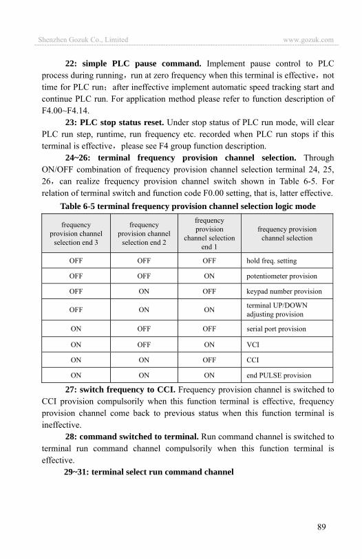
89
22: simple PLC pause command. Implement pause control to PLC process during running run at zero frequency when this terminal is effective nottime for PLC run after ineffective implement automatic speed tracking start and continue PLC run. For application method please refer to function description of F4.00~F4.14.
23: PLC stop status reset. Under stop status of PLC run mode, will clear PLC run step, runtime, run frequency etc. recorded when PLC run stops if this terminal is effective please see F4 group function description.
24~26: terminal frequency provision channel selection. Through ON/OFF combination of frequency provision channel selection terminal 24, 25, 26 can realize frequency provision channel switch shown in Table 6-5. For relation of terminal switch and function code F0.00 setting, that is, latter effective.
Table 6-5 terminal frequency provision channel selection logic mode
frequency provision channel
selection end 3
frequency provision channel
selection end 2
frequency provision
channel selection end 1
frequency provision channel selection
OFF OFF OFF hold freq. setting
OFF OFF ON potentiometer provision
OFF ON OFF keypad number provision
OFF ON ON terminal UP/DOWN adjusting provision
ON OFF OFF serial port provision
ON OFF ON VCI
ON ON OFF CCI
ON ON ON end PULSE provision
27: switch frequency to CCI. Frequency provision channel is switched to CCI provision compulsorily when this function terminal is effective, frequency provision channel come back to previous status when this function terminal is ineffective.
28: command switched to terminal. Run command channel is switched to terminal run command channel compulsorily when this function terminal is effective.
29~31: terminal select run command channel
Shenzhen Gozuk Co., Limited www.gozuk.com---------------------------------------------------------------------------------------------------------------------------

90
Table 6-6 Run command channel logic mode
Run command channel selection
terminal 3
Run command channel selection
terminal 2
Run command channel selection
terminal 1 Run command channel
OFF OFF OFF hold run command channel
OFF OFF ON keypad run command channel
OFF ON OFF end run command channel (keypad STOP command ineffective)
OFF ON ON end run command channel (keypad STOP command effective)
ON OFF OFF serial port run command channel(keypad STOP command ineffective)
ON OFF ON serial port run command channel(keypad STOP command effective)
Can realize control command selection shown in Table 6-6 by ON/OFF combination of run command channel selection terminal For relation of terminal switch and function code F0.00 setting, that is, latter effective.
32: swing frequency jump-in. When swing frequency start mode is manual jump-in swing frequency function effective if this terminal effective see F6 function parameter description.
33: exterior interruption input. The inverter close off output and run at zero frequency during running upon receiving exterior interruption signal. The inverter implement automatic speed tracking start-up to resume running once external interruption signal is relieved.
34: interior counter clearing end. To clear built-in counter in the inverter with cooperation of counter triggering signal.
35: interior counter triggering end. Counting pulse input port of built-in counter pulse max. frequency: 200Hz see function code F5.24, F5.25.
36: interior timer clearing end. To clear built-in timer in the inverter with cooperation of timer triggering signal.
37: interior timer triggering end. Please see function description for parameter F5.27.
38: pulse frequency input(only effective to X7,X8). Only effective for multifunction input terminal X7, X8 this function terminal receive pulse signal as frequency provision, for relation between inputted signal pulse frequency and set frequency in detail, please refer to F7 group parameter.
Shenzhen Gozuk Co., Limited www.gozuk.com---------------------------------------------------------------------------------------------------------------------------
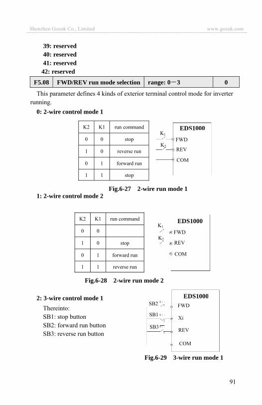
91
39: reserved40: reserved 41: reserved
42: reserved
This parameter defines 4 kinds of exterior terminal control mode for inverter running.
0: 2-wire control mode 1
1: 2-wire control mode 2
2: 3-wire control mode 1Thereinto: SB1: stop button SB2: forward run button SB3: reverse run button
F5.08 FWD/REV run mode selection range: 0 3 0
Fig.6-27 2-wire run mode 1
K2 K1 run command
0 0 stop
1 0 reverse run
0 1 forward run
1 1 stop
EDS1000
FWD
REV
COM
K1
K2
Fig.6-28 2-wire run mode 2
K2 K1 run command
0 0
1 0 stop
0 1 forward run
1 1 reverse run
EDS1000
FWD
REV
COM
K1
K2
Fig.6-29 3-wire run mode 1
EDS1000FWD
REV
COM
Xi
SB2
SB1
SB3
Shenzhen Gozuk Co., Limited www.gozuk.com---------------------------------------------------------------------------------------------------------------------------

92
Xi is multifunction input terminal of X1~X8 here should define its corresponding terminal function as No. 19 “3-wire run control” function.
3: 3-wire control mode 2 SB1: stop button SB2: run button
Xi is multifunction input terminal X1~X8, here should define its corresponding terminal function as No. 19 “3-wire run control” function.
The inverter restores after failure and start at once if run command channel selecting terminal and terminal FWD/REV is effective during warning alarm stop.
This function code defines varying rate of the set frequency when it’s modified by UP/DOWN terminal.
OC1~OC4 open collector output terminal Table 6-7 shows option of above 4 function parameter choosing same output terminal function repeatedly is allowed.
Table 6-7 output terminal function selection table
Item Corresponding function Item Corresponding function
0 Inverter running signal (RUN) 1 Frequency arriving signal (FAR)
2 Frequency level detecting signal (FDT1) 3 Reserved
F5.09 UP/DOWN velocity range: 0.01 99.99Hz/S 1.00Hz/S
F5.10 Open circuit collector output terminal OC1 output setting range: 0~24 0
F5.11 Open circuit collector output terminal OC2 output setting range: 0~24 0
F5.12 Open circuit collector output terminal OC3 output setting range: 0~24 0
F5.13 Open circuit collector output terminal OC4 output setting range: 0~24 0
K2 run direction selection
0 Forward run
1 Reverse run
FWD
REV
COM
Xi
EDS1000SB2
SB1
K2
Fig.6-30 3-wire run mode 2
Shenzhen Gozuk Co., Limited www.gozuk.com---------------------------------------------------------------------------------------------------------------------------
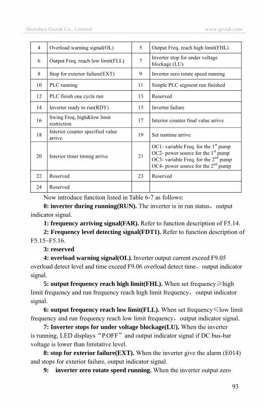
93
4 Overload warning signal(OL) 5 Output Freq. reach high limit(FHL)
6 Output Freq. reach low limit(FLL) 7 Inverter stop for under voltage blockage (LU)
8 Stop for exterior failure(EXT) 9 Inverter zero rotate speed running
10 PLC running 11 Simple PLC segment run finished
12 PLC finish one cycle run 13 Reserved
14 Inverter ready to run(RDY) 15 Inverter failure
16 Swing Freq. high&low limit restriction 17 Interior counter final value arrive
18 Interior counter specified value arrive 19 Set runtime arrive
20 Interior timer timing arrive 21
OC1- variable Freq. for the 1st pump OC2- power source for the 1st pump OC3- variable Freq. for the 2nd pump OC4- power source for the 2nd pump
22 Reserved 23 Reserved
24 Reserved
Now introduce function listed in Table 6-7 as follows: 0: inverter during running(RUN). The inverter is in run status output
indicator signal. 1: frequency arriving signal(FAR). Refer to function description of F5.14. 2: Frequency level detecting signal(FDT1). Refer to function description of
F5.15~F5.16.3: reserved4: overload warning signal(OL). Inverter output current exceed F9.05
overload detect level and time exceed F9.06 overload detect time output indicator signal.
5: output frequency reach high limit(FHL). When set frequency high limit frequency and run frequency reach high limit frequency output indicator signal.
6: output frequency reach low limit(FLL). When set frequency low limit frequency and run frequency reach low limit frequency output indicator signal.
7: Inverter stops for under voltage blockage(LU). When the inverter is running, LED displays P.OFF and output indicator signal if DC bus-bar voltage is lower than limitative level.
8: stop for exterior failure(EXT). When the inverter give the alarm (E014) and stops for exterior failure, output indicator signal.
9: inverter zero rotate speed running. When the inverter output zero
Shenzhen Gozuk Co., Limited www.gozuk.com---------------------------------------------------------------------------------------------------------------------------
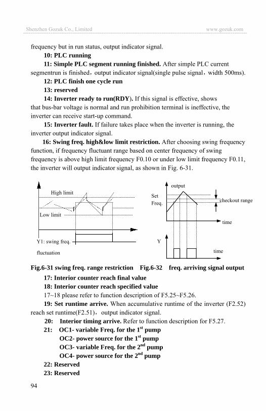
94
frequency but in run status, output indicator signal. 10: PLC running 11: Simple PLC segment running finished. After simple PLC current
segmentrun is finished output indicator signal(single pulse signal width 500ms). 12: PLC finish one cycle run 13: reserved 14: Inverter ready to run(RDY). If this signal is effective, shows
that bus-bar voltage is normal and run prohibition terminal is ineffective, the inverter can receive start-up command.
15: Inverter fault. If failure takes place when the inverter is running, the inverter output indicator signal.
16: Swing freq. high&low limit restriction. After choosing swing frequency function, if frequency fluctuant range based on center frequency of swing frequency is above high limit frequency F0.10 or under low limit frequency F0.11, the inverter will output indicator signal, as shown in Fig. 6-31.
Fig.6-31 swing freq. range restriction Fig.6-32 freq. arriving signal output17: Interior counter reach final value 18: Interior counter reach specified value 17~18 please refer to function description of F5.25~F5.26. 19: Set runtime arrive. When accumulative runtime of the inverter (F2.52)
reach set runtime(F2.51) output indicator signal. 20: Interior timing arrive. Refer to function description for F5.27. 21: OC1- variable Freq. for the 1st pump
OC2- power source for the 1st pump OC3- variable Freq. for the 2nd pump OC4- power source for the 2nd pump
22: Reserved23: Reserved
Y1: swing freq.
fluctuation
Low limit
High limit output
Set Freq.
time
time
Y
checkout range
Shenzhen Gozuk Co., Limited www.gozuk.com---------------------------------------------------------------------------------------------------------------------------

95
24: ReservedF5.14 Freq. arriving(FAR)detect range range: 0.00 50.00Hz 5.00Hz
This parameter is supplementary definition to No. 1 function in Table 6-7.As shown in Fig.6-32 when output frequency of the inverter is within high&low detect range of set frequency output pulse signal.
F5.15~F5.16 is supplementary definition to No.2 function in Table 6-7, introduce as follows: When output frequency exceed the set frequency(FDT1 electric level)output indicator signal till output frequency descend to be some frequency(FDT1 electric level-FDT1 lag) lower than FDT1 electric levelas shown in Fig.6-33.
0: output frequency(0 high limit frequency) 1: set frequency(0 high limit frequency) 2: output current(0 2 rated current) 3: output voltage(0 1.2 load motor rated voltage) 4: bus-bar voltage(0 800V)5: PID provision (0.00-10.00V) 6: PID feedback (0.00-10.00V) 7: reserved 8: reserved 9: reserved
F5.18 Analog output(AO1)gain range: 0.00 2.00 1.00
F5.19 Analog output(AO1) offset range: 0.00 10.00V 0.00
For AO1 and AO2 analog output, the user can modify display measuring range or emend meter head error by adjusting output gain if necessary.
Same as F5.17 function parameter description.
F5.15 FDT1(freq. level) electric level
range: 0.00 high limit frequency 10.00Hz
F5.16 FDT1 lag range: 0.00 50.00Hz 1.00Hz
Output freq.FDT1 electric level
time
time
Y
FDT1 lag
Fig.6-33 freq. level detecting
F5.17 Analog output(AO1)selection range: 0 9
F5.20 Analog output(AO2)selection range: 0 9 0
Shenzhen Gozuk Co., Limited www.gozuk.com---------------------------------------------------------------------------------------------------------------------------
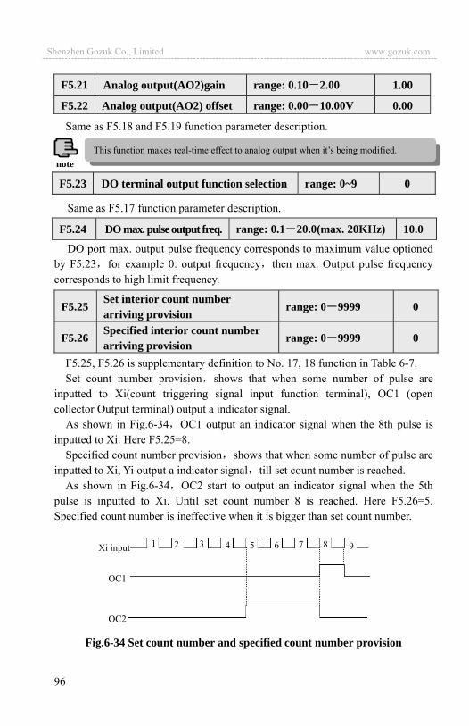
96
F5.21 Analog output(AO2)gain range: 0.10 2.00 1.00
F5.22 Analog output(AO2) offset range: 0.00 10.00V 0.00
Same as F5.18 and F5.19 function parameter description.
Same as F5.17 function parameter description.
DO port max. output pulse frequency corresponds to maximum value optioned by F5.23 for example 0: output frequency then max. Output pulse frequency corresponds to high limit frequency.
F5.25, F5.26 is supplementary definition to No. 17, 18 function in Table 6-7. Set count number provision shows that when some number of pulse are
inputted to Xi(count triggering signal input function terminal), OC1 (open collector Output terminal) output a indicator signal.
As shown in Fig.6-34 OC1 output an indicator signal when the 8th pulse is inputted to Xi. Here F5.25=8.
Specified count number provision shows that when some number of pulse are inputted to Xi, Yi output a indicator signal till set count number is reached.
As shown in Fig.6-34 OC2 start to output an indicator signal when the 5th pulse is inputted to Xi. Until set count number 8 is reached. Here F5.26=5. Specified count number is ineffective when it is bigger than set count number.
Fig.6-34 Set count number and specified count number provision
F5.23 DO terminal output function selection range: 0~9 0
F5.24 DO max. pulse output freq. range: 0.1 20.0(max. 20KHz) 10.0
F5.25 Set interior count number arriving provision
range: 0 9999 0
F5.26 Specified interior count number arriving provision
range: 0 9999 0
1 2 3 4 5 6 7 8 9Xi input
OC1
OC2
This function makes real-time effect to analog output when it’s being modified.note
Shenzhen Gozuk Co., Limited www.gozuk.com---------------------------------------------------------------------------------------------------------------------------
97
This parameter is used to set timing time of interior timer of the inverter. The timer is activated by exterior triggering end(triggering end selected by F5.00~F5.07), the timer begins timing upon receiving exterior triggering signal, after it’s up to timing time one effective pulse signal of 0.5s will be outputted from relative OC end.
6.7 Traverse special function parameter group: F6
0: traverse function ineffective 1: traverse function effective
LED 1st bit: jump-in mode 0: automatic jump-in mode. After start-up run at traverse preset frequency
for a period of time, then enter into traverse operation automatically. 1: terminal manual run mode. When set the multifunction terminal
Xi(Xi=X1~X8)to function 32 and it’s effective enter into traverse state quit traverse state if ineffective and run frequency is at traverse preset frequency.
LED 2nd bit: 0: changing traverse amplitude. Amplitude AW varies with center
frequency for its changing rate please see F6.02 definition. 1: fixed traverse amplitude. Amplitude AW is determined by high limit
frequency and F6.02.
changing amplitude: AW=center frequency F6.02 fixed amplitude: AW=high limit frequency F6.02
As shown in Fig.6-35.If this parameter is set to 0, no jumping frequency.
F6.00 Traverse function selection range: 0, 1 0
F6.01 Traverse run mode range: LED 1st bit: 0, 1 LED 2nd bit: 0, 1 00
F6.02 Traverse amplitude threshold range: 0.0 50.0(%) 0.0(%)
F6.03 Sudden jumping freq. range: 0.0 50.0 0.0(%)
F5.27 Interior timing setting range: 0.1 6000.0s 60.0
Traverse center frequency input setting channel is set by F0.00 function.!
Traverse run frequency is restricted by high limit, low limit frequency if set improperly abnormal traverse operaion arise.
note
Shenzhen Gozuk Co., Limited www.gozuk.com---------------------------------------------------------------------------------------------------------------------------

98
Whole time for a cycle including traverse rising, descending process.
Define runtime of traverse rising segment=F6.04 F6.05 (s) runtime of descending segment = F6.04 (1-F6.05) (s). Please refer to description in Fig.6-35.
F6.06 is used for defining inverter run frequency before entering into traverse operation. When automatic start-up mode is optioned F6.07 is used for setting holding time running at traverse preset frequency before enter into traverse operation When manual start-up mode is optioned F6.07 setting is ineffective. Please see description in Fig.6-35.
F6.04 Traverse cycle range: 0.1 999.9S 10.0S
F6.06 Traverse preset frequency range: 0.00 400.00Hz 0.00Hz
F6.07 Traverse preset frequency latency time range: 0.0 6000S 0.0S
F6.05 Triangle wave rising time
range: 0.0 98.0(%)(traverse cycle) 50.0(%)
traverse preset freq.
run command
Dece per Dece time
Accel per accel time
weavingstart-up latency time F6.07 traverse cycle
Run freq. Hz
a
-AW +AW
weaving sudden jumping freq. =AW*F6.03
stop command
triangle wave rising time
traverse low limit FL
center freq.Fset traverse high limit Fh
Traverse amplitude AW=Fset*F6.02
Fig. 6-35 Traverse
time
Shenzhen Gozuk Co., Limited www.gozuk.com---------------------------------------------------------------------------------------------------------------------------
99
6.8 Frequency provision function parameter group: F7
The inverter can decide FWD run or REV run according to YCI input when YCI is selected to be frequency provision(i.e. F0.00=6). YCI frequency defined in F2.09 may be positive or negative when YCI isn’t selected to be frequency provision.
Shown as the figure: 0—dead band the frequency is negative. 5V dead band—5V+dead band YCI set frequency is 0
5V+ dead band—10V the frequency is positive
F7.00 VCI min. provision range: 0.00 F7.02 0.0V
F7.01 VCI min. provision corresponding freq.
range: 0.00 high limit frequency 0.00Hz
F7.02 VCI max. provision range: 0.00 10.00V 9.9V
F7.03 VCI max. provision corresponding freq.
range: 0.00 high limit frequency 50.00Hz
F7.04 CCI min. provision range: 0.00 F7.06 0.00V
F7.05 CCI min. provision corresponding freq.
range: 0.00 high limit frequency 0.00Hz
F7.06 CCI max. provision range: 0.00 10.00V 9.9V
F7.07 CCI max. provision corresponding freq.
range: 0.00 high limit frequency 50.00Hz
F7.08 YCI min. provision range: 0.00 F7.10 0.00V
F7.09 YCI min. provision corresponding freq.
range: 0.00 high limit frequency(REV) 0.00Hz
F7.10 YCI max. provision range: 0.00 10.00V/5V 9.9V
F7.11 YCI max. provision corresponding freq.
range: 0.00 high limit frequency(FWD) 50.00Hz
F7.12 YCI dead area setting range: 0.00V 2.00V 0.10V
F7.13 PULSE max. input pulse range: 0.01 20.0K 10.0K
F7.14 PULSE min. provision range: 0.0 F7.16 0.0K
F7.15 PULSE min. provision corresponding freq.
range: 0.00 high limit frequency 0.00Hz
Shenzhen Gozuk Co., Limited www.gozuk.com---------------------------------------------------------------------------------------------------------------------------
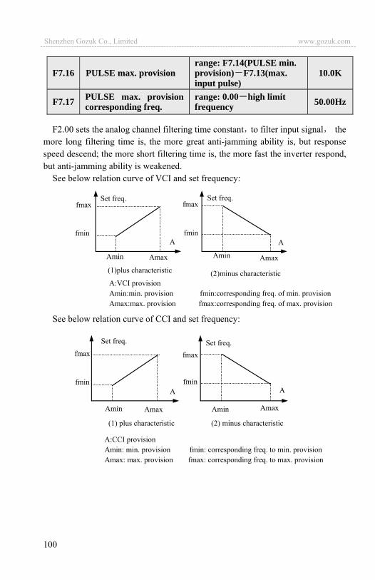
100
F2.00 sets the analog channel filtering time constant to filter input signal the more long filtering time is, the more great anti-jamming ability is, but response speed descend; the more short filtering time is, the more fast the inverter respond, but anti-jamming ability is weakened.
See below relation curve of VCI and set frequency:
See below relation curve of CCI and set frequency:
F7.16 PULSE max. provision range: F7.14(PULSE min. provision) F7.13(max. input pulse)
10.0K
F7.17 PULSE max. provision corresponding freq.
range: 0.00 high limit frequency 50.00Hz
Set freq. Set freq. fmax
fmin A A
Amin Amin Amax Amax (1)plus characteristic (2)minus characteristic A:VCI provision Amin:min. provision fmin:corresponding freq. of min. provision Amax:max. provision fmax:corresponding freq. of max. provision
fmax
fmin
Set freq. Set freq. fmax
fmin A A
Amin Amin Amax Amax
(1) plus characteristic (2) minus characteristic
A:CCI provision Amin: min. provision fmin: corresponding freq. to min. provision Amax: max. provision fmax: corresponding freq. to max. provision
fmax
fmin
Shenzhen Gozuk Co., Limited www.gozuk.com---------------------------------------------------------------------------------------------------------------------------
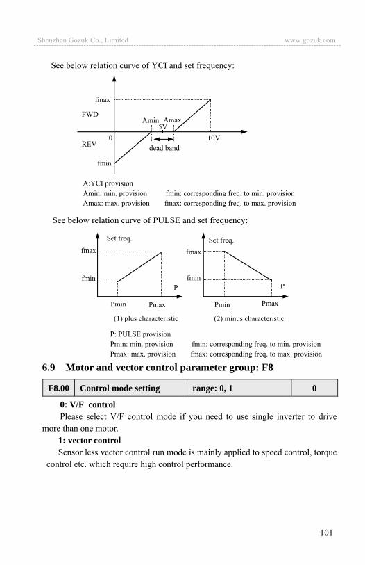
101
See below relation curve of YCI and set frequency:
See below relation curve of PULSE and set frequency:
6.9 Motor and vector control parameter group: F8
0: V/F controlPlease select V/F control mode if you need to use single inverter to drive
more than one motor. 1: vector control Sensor less vector control run mode is mainly applied to speed control, torque
control etc. which require high control performance.
Set freq. Set freq. fmax
fmin P P
Pmin Pmin Pmax Pmax
(1) plus characteristic (2) minus characteristic
P: PULSE provision Pmin: min. provision fmin: corresponding freq. to min. provision Pmax: max. provision fmax: corresponding freq. to max. provision
fmax
fmin
A:YCI provision Amin: min. provision fmin: corresponding freq. to min. provision Amax: max. provision fmax: corresponding freq. to max. provision
0 10V 5V
fmax
fmin
FWD
REV dead band
Amax Amin
F8.00 Control mode setting range: 0, 1 0
Shenzhen Gozuk Co., Limited www.gozuk.com---------------------------------------------------------------------------------------------------------------------------

102
Please set above parameters according to rated data of motor drived by the inverter for the sake of safe running.
The inverter will set F8.07-F8.10 to be default standard motor parameter everty time after motor rated data modified.
This parameter is used to limit torque current outputted from speed adjustor. Torque limit value 50.0 200.0% is percentage of inverter rated current; torque
limit=100% i.e., set torque current limit is rated current of the frequency inverter.
By F8.13, F8.14 you can set proportion gain and integral time of the speed adjustor to change speed response characteristic of vector control.
F8.01 Motor rated voltage range: 1 480V Depend on device type
F8.02 Motor rated current range: 0.1 999.9A Depend on device type
F8.03 Motor rated frequency range: 1.00 400.0Hz Depend on device type
F8.04 Motor rated speed range: 1 9999r/min Depend on device type
F8.05 Motor pole quantity range: 2 14 Depend on device type
F8.06 Motor rated power range: 0.1 999.9KW Depend on device type
F8.07 Motor stator resistance range: 0.000 9.999ohm Depend on
device type
F8.08 Motor rotorresistance range: 0.000 9.999ohm Depend on
device type
F8.09 Motor statorleakage inductance range: 0.0 999.9mH Depend on
device type
F8.10 Motor rotorleakage inductance range: 0.0 999.9mH Depend on
device type
F8.11 Motor mutual inductance range: 0.0 999.9mH Depend on
device type
F8.13 Speed loop proportion gain range: 0.000 6.000 0.700
F8.14 Speed loop integral time constant range: 0.000 9.999 0.360
F8.12 Torque limit range: 50.0 200.0% 150.0%
Shenzhen Gozuk Co., Limited www.gozuk.com---------------------------------------------------------------------------------------------------------------------------
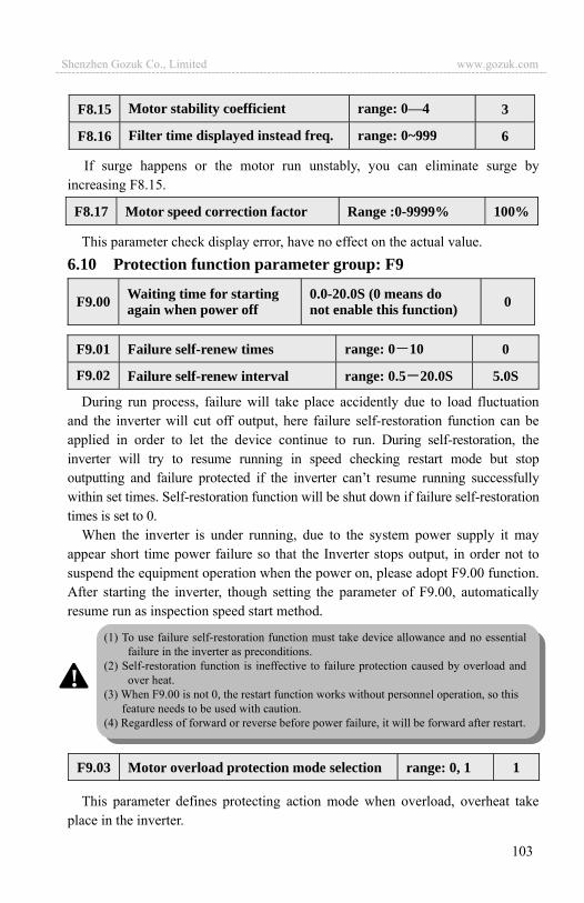
103
If surge happens or the motor run unstably, you can eliminate surge by increasing F8.15.
This parameter check display error, have no effect on the actual value. 6.10 Protection function parameter group: F9
During run process, failure will take place accidently due to load fluctuation and the inverter will cut off output, here failure self-restoration function can be applied in order to let the device continue to run. During self-restoration, the inverter will try to resume running in speed checking restart mode but stop outputting and failure protected if the inverter can’t resume running successfully within set times. Self-restoration function will be shut down if failure self-restoration times is set to 0.
When the inverter is under running, due to the system power supply it may appear short time power failure so that the Inverter stops output, in order not to suspend the equipment operation when the power on, please adopt F9.00 function. After starting the inverter, though setting the parameter of F9.00, automatically resume run as inspection speed start method.
This parameter defines protecting action mode when overload, overheat take place in the inverter.
F9.01 Failure self-renew times range: 0 10 0
F9.02 Failure self-renew interval range: 0.5 20.0S 5.0S
F9.03 Motor overload protection mode selection range: 0, 1 1
F8.15 Motor stability coefficient range: 0—4 3
F8.16 Filter time displayed instead freq. range: 0~999 6
F9.00 Waiting time for starting again when power off
0.0-20.0S (0 means do not enable this function) 0
F8.17 Motor speed correction factor Range :0-9999% 100%
(1) To use failure self-restoration function must take device allowance and no essential failure in the inverter as preconditions.
(2) Self-restoration function is ineffective to failure protection caused by overload and over heat.
(3) When F9.00 is not 0, the restart function works without personnel operation, so this feature needs to be used with caution.
(4) Regardless of forward or reverse before power failure, it will be forward after restart.
!
Shenzhen Gozuk Co., Limited www.gozuk.com---------------------------------------------------------------------------------------------------------------------------
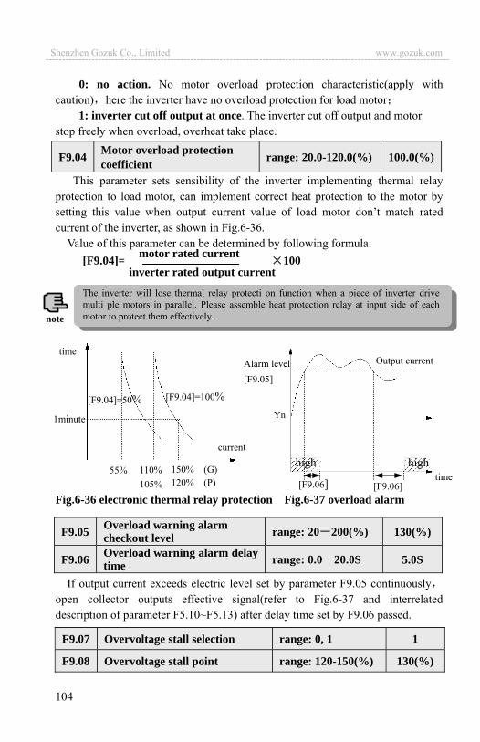
104
0: no action. No motor overload protection characteristic(apply with caution) here the inverter have no overload protection for load motor
1: inverter cut off output at once. The inverter cut off output and motor stop freely when overload, overheat take place.
This parameter sets sensibility of the inverter implementing thermal relay protection to load motor, can implement correct heat protection to the motor by setting this value when output current value of load motor don’t match rated current of the inverter, as shown in Fig.6-36.
Value of this parameter can be determined by following formula: [F9.04]= 100
Fig.6-36 electronic thermal relay protection Fig.6-37 overload alarm
If output current exceeds electric level set by parameter F9.05 continuouslyopen collector outputs effective signal(refer to Fig.6-37 and interrelated description of parameter F5.10~F5.13) after delay time set by F9.06 passed.
F9.04 Motor overload protection coefficient range: 20.0-120.0(%) 100.0(%)
motor rated current inverter rated output current
F9.05 Overload warning alarm checkout level range: 20 200(%) 130(%)
F9.06 Overload warning alarm delay time range: 0.0 20.0S 5.0S
time
current
[F9.04]=100%[F9.04]=50%1minute
55% 110% 105%
150% (G) 120% (P) time
Alarm level [F9.05]
Output current
highhigh
Yn
[F9.06] [F9.06]
F9.07 Overvoltage stall selection range: 0, 1 1
F9.08 Overvoltage stall point range: 120-150(%) 130(%)
The inverter will lose thermal relay protecti on function when a piece of inverter drive multi ple motors in parallel. Please assemble heat protection relay at input side of each motor to protect them effectively. note
Shenzhen Gozuk Co., Limited www.gozuk.com---------------------------------------------------------------------------------------------------------------------------
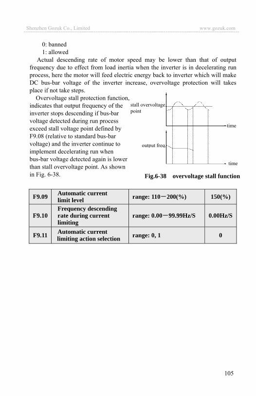
105
0: banned 1: allowed
Actual descending rate of motor speed may be lower than that of output frequency due to effect from load inertia when the inverter is in decelerating run process, here the motor will feed electric energy back to inverter which will make DC bus-bar voltage of the inverter increase, overvoltage protection will takes place if not take steps.
Overvoltage stall protection function, indicates that output frequency of the inverter stops descending if bus-bar voltage detected during run process exceed stall voltage point defined by F9.08 (relative to standard bus-bar voltage) and the inverter continue to implement decelerating run when bus-bar voltage detected again is lower than stall overvoltage point. As shown in Fig. 6-38.
F9.09 Automatic current limit level range: 110 200(%) 150(%)
F9.10 Frequency descending rate during current limiting
range: 0.00 99.99Hz/S 0.00Hz/S
F9.11 Automatic current limiting action selection range: 0, 1 0
time
time
stall overvoltage point
output freq.
Fig.6-38 overvoltage stall function
Shenzhen Gozuk Co., Limited www.gozuk.com---------------------------------------------------------------------------------------------------------------------------

106
By automatic current limiting function the inverter can limit load current not to exceed automatic current limiting level set by F9.09 to avoid tripping out for failure caused by rushing current. This function is especially suitable for some biggish inertia or acutely changing load occasion.
Automatic current limiting (F9.09) defines current threshold value of automatic current limiting action, its value is the percentage relative to inverter rated current.
Frequency descending rate during current limiting (F9.10) defines adjusting rate to output frequency during automatic current limiting action.
If frequency descending rate during automatic current limiting F9.10 is too small inverter isn’t easy to get rid of automatic current limiting state which may cause overload failure finally If descending rate F9.10 is too big, the inverter may be in generating state for long time which will cause overvoltage protection.
Automatic current limiting function is effective in accelerating decelerating state and whether it’s effective in constant speed run state is determined by automatic current limiting action selection (F9.11).
F9.11=0 indicates that automatic current limiting is ineffective during constant speed running
F9.11=1 indicates that automatic current limiting is effective during constant speed running
Output frequency may varies during automatic current limiting action soautomatic current limiting function is not suitable for occasion demanding stable output frequency during constant speed run.
6.11 Failure record function parameter group: Fd
0: no failure 1 23: failure E0.01-E0.23 please see chapter 7 for specified failure type
Fd.00 Previous one time failure record range: 0~23 0
Fd.01 Previous two time failure record range: 0~23 0
Fd.02 Previous three time failure record range: 0~23 0
Fd.03 Previous four time failure record range: 0~23 0
Fd.04 Previous five time failure record range: 0~23 0
Fd.05 Previous six time failure record range: 0~23 0
Shenzhen Gozuk Co., Limited www.gozuk.com---------------------------------------------------------------------------------------------------------------------------

107
6.12 Password and manufacturer function parameter group: FF
User password setting function is used for prohibiting unauthorized personnel from consulting and modifying function parameter.
Set this function code to 0000 when user password function isn’t wanted. First input 4 bits number as user password and press key to confirm,
then the password will come into effect at once. Password modification: Enter into password verification state by pressing key, after inputting
primary 4 bits password parameter editing state is available choose FF.00(here FF.00=0000) input new password and press key to confirm then the password come into effect at once.
Setting function for the manufacturer, user need not modify it.
Fd.06 Set freq. at previous failure range: 0-high limit 0
Fd.07 Output freq. at previous failure range: 0-high limit 0
Fd.08 Output current at previous failure range: 0-999.9A 0
Fd.09 Output volt. at previous failure range: 0-999V 0
Fd.10 DC bus-bar volt. at previous failure range: 0~800V 0
Fd.11 Load motor speed at previous failure range: 0~9999 0
Fd.12 Module temp. at previous failure range: 0~100 0
Fd.13 Input end state at previous failure 0
Fd.14 Accu. runtime at previous failure range: 0~65535h 0
FF.00 User password range: 0000 9999 1
FF.01 Manufacturer password range: 0000 9999 0000
Please keep the password you set without fail, in case the password is missing please consult the manufacturer.
note
Shenzhen Gozuk Co., Limited www.gozuk.com---------------------------------------------------------------------------------------------------------------------------

108
6.13 Stop assistant function parameter group: FA
Auxiliary DC brake means when the inverter stop DC brake is finished give the second stage DC braking. Role in some special circumstances require rapid braking, and stop long time in the state of DC braking, but to prevent motor heat circumstances.
V(%)
t(s)
F1.08
FA.01
0F1.07 FA.00
FA.00 Auxiliary DC brake time Range 0.0 20.0s 0.0sFA.01 Auxiliary DC brake voltage Range 0 15 % 0
FA.02 Reserved FA.03 Reserved
Shenzhen Gozuk Co., Limited www.gozuk.com---------------------------------------------------------------------------------------------------------------------------

109
7 Troubleshooting 7.1 Failure and countermeasure
Possible failure types in EDS1000 are shown in Table 7-1 and failure code is from E001 to E023. Some failure code is reserved for intelligent automatic diagnosis function which will be executed continuously in future. When failure takes place in the inverter, the user should check according to note of this table first and record failure phenomena detailedly. Please contact our after-sale service and technical support Department or agent in your local place when technical service is needed.
Table 7-1 Failure type and the countermeasure Failure code Failure type Possible reason Countermeasure
E001 overcurrent during accelerating process
Accelerating time is too short Prolong accelerating time
Improper V/F curve Adjust V/F curve setting adjust manual torque boost or change to automatic torque boost
Restart rotating motor Set speed checking restart function Low power source voltage Check input power supply Too small power of the inverter Choose inverter with high-power
E002 overcurrent during decelerating process
Decelerating time is too short Prolong decelerating time
Have potential energy load or big Inertia load
Increase braking power of external energy consumption braking subassembly
Power of inverter is a bit small Choose inverter with high-powerE003 overcurrent
during constant speed process
Load change suddenly orHave unwonted phenomena Check or reduce break of the load
Accel/Decel time is set to too short
Prolong accelerating decelerating time properly
low power source voltage Check input power supply Power of inverter is a bit small Choose inverter with high-power
E004 overvoltage during accelerating process
Unwonted input voltage Check input power supply
Accel time is set to too short Prolong accelerating time properly
Restart rotating motor Set speed checking restart function E005 overvoltage
during decelerating process
Decelerating time is too short Prolong decelerating time
Have potential energy load or big inertia load
Increase braking power of external energy consumption braking subassembly
E006 Overvoltage during constant speed process
Unwonted input voltage Check input power supply Accel/Decel time is set to too short
Prolong accelerating deceleratingtime properly
Input voltage change abnormally Assemble reactor
Load inertia is a bit big Use energy consumptionsubassembly
E007 Inverter control power supply overvoltage
Unwonted input voltage Check input power supply or look for service
Shenzhen Gozuk Co., Limited www.gozuk.com---------------------------------------------------------------------------------------------------------------------------
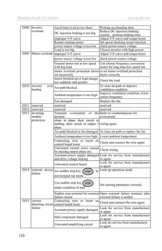
110
E008 Inverter overload
Accel time is set to too short Prolong accelerating time
DC injection braking is too big Reduce DC injection brakingcurrent prolong braking time
improper V/F curve Adjust V/F curve and torque boostRestart rotating motor Set speed checking restart functionpower source voltage is too low check power source voltageLoad is too big Choose inverter with high-power
E009 Motor overload improper V/F curve Adjust V/F curve and torque boost power source voltage is too low check power source voltage General motor run at low speed with big load
Can choose frequency conversion motor for long time low speed run
motor overload protection factor set incorrectly
to set motor overload protection factor correctly
motor blocked up or load change too suddenly and quickly Check the load
E010 inverter over heating Air-path blocked To clear air-path or improve
ventilation condition
Ambient temperature is too high Improve ventilation condition, lower carrier frequency
Fan damaged Replace the fan E011 reserved reserved reservedE012 reserved reserved reservedE013 Inverting
module protection
Transient overcurrent of the inverter
Refer to countermeasure forovercurrent
phase to phase short circuit or earthing short circuit of output 3 phase
wiring again
Air-path blocked or fan damaged To clear air-path or replace the fan Ambient temperature is too high Lower ambient temperature Connecting wire or insert on control board loose Check and connect the wire again
Unwonted current wave caused by missing output phase etc. Check wiring
Assistant power supply damaged and drive voltage lacking
Look for service from manufacturer or agent
Unwonted control board Look for service from manufacturer or agent
E014 external device failure
use sudden stop key in non-keypad run mode
Look up operation mode
Use sudden stop key under condition of stall
Set running parameter correctly
Sudden stop terminal for external failure closed
Open external failure terminal after external failure is settled
E015 current detecting circuit failure
Connecting wire or insert on control board loose Check and connect the wire again
Assistant power supply damaged Look for service from manufacturer or agent
Hall component damaged Look for service from manufacturer or agent
Unwonted amplifying circuit Look for service from manufacturer or agent
Shenzhen Gozuk Co., Limited www.gozuk.com---------------------------------------------------------------------------------------------------------------------------
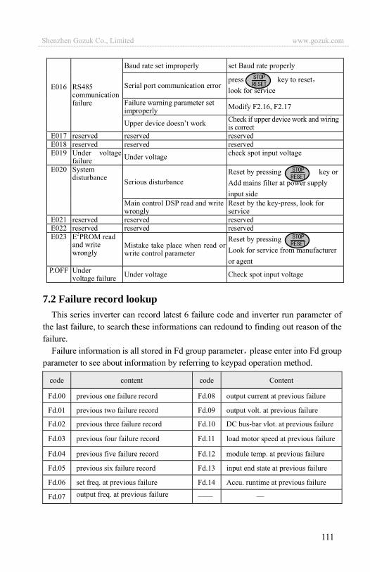
111
E016 RS485 communication failure
Baud rate set improperly set Baud rate properly
Serial port communication error press key to resetlook for service
Failure warning parameter set improperly Modify F2.16, F2.17
Upper device doesn’t work Check if upper device work and wiring is correct
E017 reserved reserved reservedE018 reserved reserved reservedE019 Under voltage
failure Under voltage check spot input voltage
E020 System disturbance Serious disturbance
Reset by pressing key orAdd mains filter at power supply input side
Main control DSP read and write wrongly
Reset by the key-press, look for service
E021 reserved reserved reservedE022 reserved reserved reservedE023 E2PROM read
and write wrongly
Mistake take place when read or write control parameter
Reset by pressing Look for service from manufacturer or agent
P.OFF Under voltage failure Under voltage Check spot input voltage
7.2 Failure record lookup This series inverter can record latest 6 failure code and inverter run parameter of
the last failure, to search these informations can redound to finding out reason of the failure.
Failure information is all stored in Fd group parameter please enter into Fd group parameter to see about information by referring to keypad operation method.
code content code Content
Fd.00 previous one failure record Fd.08 output current at previous failure
Fd.01 previous two failure record Fd.09 output volt. at previous failure
Fd.02 previous three failure record Fd.10 DC bus-bar vlot. at previous failure
Fd.03 previous four failure record Fd.11 load motor speed at previous failure
Fd.04 previous five failure record Fd.12 module temp. at previous failure
Fd.05 previous six failure record Fd.13 input end state at previous failure
Fd.06 set freq. at previous failure Fd.14 Accu. runtime at previous failure
Fd.07 output freq. at previous failure
Shenzhen Gozuk Co., Limited www.gozuk.com---------------------------------------------------------------------------------------------------------------------------

112
7.3 Failure reset
To resume normal running when failure takes place in the inverter, you can choose following any kind of operation: (1) After you set any terminal of X1~X8 to be inputted by external RESET
(F5.00~F5.07=11), you can open it after connected to COM. (2) When failure code is displayed press key after restoration is
confirmed.(3) Cut off power supply.
(1) Before reset you must find out reason of failure downright and eliminate itotherwise may cause permanent damage to the inverter.
(2) If can’t reset or failure takes place again after resetting, should look for reason and continuous resetting will damage the inverter.
(3) Reset should take place 5 minutes after overload, overheat protection action.
!
Shenzhen Gozuk Co., Limited www.gozuk.com---------------------------------------------------------------------------------------------------------------------------

113
8 Maintenance 8.1 Routine maintenance
When you use EDS1000 series you must assemble and operate it according to demand listed in this service manual strictly. During run state, temperature, humidity, vibration and aging parts may affect it. To avoid this, it is recommended to perform routine inspections.
Table 8-1 Daily inspection items Period Inspection
item Inspection content Criterion daily periodic
Run state parameter
(1)output current (1)within range of rated value
(2)output voltage (2)within range of rated value
(3)inside temp. (3)temp. increment < 35
Cooling system
(1)installing ambient (1)good ventilation, unblocked air-path
(2)local fan (2)rotate normally without abnormal noise
Motor (1)heating (1)no abnormality
(2)noise (2)even
Inverter
(1) vibration, heating (1)vibration balanced, proper wind temp.
(2)noise (2) without abnormal sound
(3)fixation of lead, terminal (3)fixed screw don’t loose
Run ambient
(1)temperature, humidity (1)-10 ~+40
40 ~50 used in lower volume or execute compulsory heat dissipating
(2)dust, water and leakage (2)no water leakage imprint, no dust
(3)gas (3)no peculiar smell
Recommend to inspect with following instrument: Input voltage: electric voltmeter output voltage: rectifying voltmeter
inputoutput current: pincers ammeter. 8.2 Inspection and replacement of damageable parts
Some component parts in the inverter will be abraded or bear descending performance for long-term usage to assure that the inverter can run stably and reliably, it is recommended to perform defending maintenance and replace corresponding parts if necessary. (1) cooling fan
Abnormal noise, even oscillation may take place if the fan have wearingbearing, aging blade, here replacement of the fan should be considered.
Shenzhen Gozuk Co., Limited www.gozuk.com---------------------------------------------------------------------------------------------------------------------------
114
(2) filter electrolyte capacitance When frequent-changing load causes increasing pulsant current and aging
electrolyte under high ambient temperature, the electrolyte capacitance may be damaged and here should replace it. 8.3 Repair guarantee(1) Within 18 months from purchasing date, if failure caused by inverter itself
takes place under normal conservation and usage, we will provide free repair service.
(2) We will take some upkeep if one of following situations takes place within period of repair guarantee. a. If did not use the inverter according to service manual strictly or did not
use it under ambient demanded in service manual , which cause failure. b. Failure caused by applying the inverter to non-normal function; c. Failure caused by self-repair, refit which is not already allowed; d. Damage caused by bad keeping, falling down from high place or other
extrinsic factor after purchasing the inverter; e. Failure caused by natural disaster or its reason such as unwonted voltage,
thunderbolt, water fog, fire, salt corroding, gas corroding, earthquake and storm etc.;
f. Make bold to tear up product logo (such as: nameplate etc.); Body serial number don’t accord with that in repair guarantee card.
(3) We calculate service fee based on actual cost, which is subject to contract if any.
(4) You can contact the agent and also our company directly if you have questions. After repair guarantee period, we shall also provide lifetime charged repair service for our products.
8.4 StorageThe user must pay attention to following points for temporary storage and
long-term storage after purchasing the inverter: (1) Avoid storing the inverter in high temperature, moist place and place of dust,
metal powder and assure good ventilation. (2) Longtime storage will cause electrolyte capacitance of low quality, so must
assure that it’s electrified for one time within 2 years and electrification time is not shorter than 5 hours and input voltage must be increased to rated value gradually by voltage adjustor.
note
Our company will also provide lifetime repair service with fee for inverter which is not within period of repair guarantee.
Shenzhen Gozuk Co., Limited www.gozuk.com---------------------------------------------------------------------------------------------------------------------------
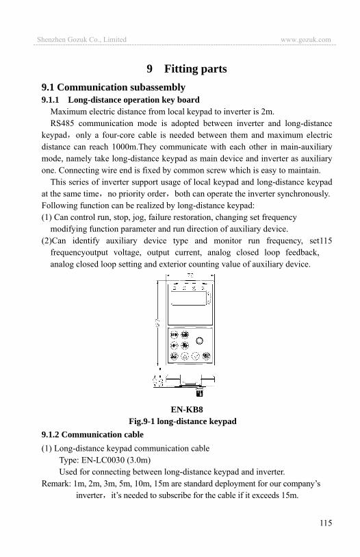
115
9 Fitting parts 9.1 Communication subassembly9.1.1 Long-distance operation key board
Maximum electric distance from local keypad to inverter is 2m. RS485 communication mode is adopted between inverter and long-distance
keypad only a four-core cable is needed between them and maximum electric distance can reach 1000m.They communicate with each other in main-auxiliary mode, namely take long-distance keypad as main device and inverter as auxiliary one. Connecting wire end is fixed by common screw which is easy to maintain.
This series of inverter support usage of local keypad and long-distance keypad at the same time no priority order both can operate the inverter synchronously. Following function can be realized by long-distance keypad: (1) Can control run, stop, jog, failure restoration, changing set frequency
modifying function parameter and run direction of auxiliary device. (2)Can identify auxiliary device type and monitor run frequency, set
frequencyoutput voltage, output current, analog closed loop feedback, analog closed loop setting and exterior counting value of auxiliary device.
EN-KB8
Fig.9-1 long-distance keypad 9.1.2 Communication cable (1) Long-distance keypad communication cable
Type: EN-LC0030 (3.0m) Used for connecting between long-distance keypad and inverter.
Remark: 1m, 2m, 3m, 5m, 10m, 15m are standard deployment for our company’s inverter it’s needed to subscribe for the cable if it exceeds 15m.
115
Shenzhen Gozuk Co., Limited www.gozuk.com---------------------------------------------------------------------------------------------------------------------------
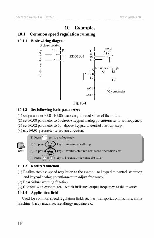
116
10 Examples10.1 Common speed regulation running 10.1.1 Basic wiring diagram
Fig.10-1
10.1.2 Set following basic parameter: (1) set parameter F8.01-F8.06 according to rated value of the motor. (2) set F0.00 parameter to 0 choose keypad analog potentiometer to set frequency. (3) set F0.02 parameter to 0 choose keypad to control start-up, stop. (4) use F0.03 parameter to set run direction.
10.1.3 Realized function(1) Realize stepless speed regulation to the motor, use keypad to control start/stop
and keypad analog potentiometer to adjust frequency. (2) Bear failure warning function. (3) Connect with cymometer which indicates output frequency of the inverter. 10.1.4 Application field
Used for common speed regulation field such as: transportation machine, china machine, baccy machine, metallurgy machine etc.
3 phase breaker RS
T
TATBTC
AO1
MUVWE
motor
L1
L2
failure waring light
GNDcymometer
EDS1000
(1) Press key to set frequency.
(2) To press key the inverter will stop.
(3) To press key inverter enter into next menu or confirm data.
(4) Press key to increase or decrease the data.
note
Shenzhen Gozuk Co., Limited www.gozuk.com---------------------------------------------------------------------------------------------------------------------------

117
10.2 Terminal control running 10.2.1 Basic wiring diagram
Fig.10-2
10.2.2 Parameter setting (1) Set parameter F8.01-F8.06 according to rated value of the motor. (2) Set F0.00 parameter to 4~6 to choose VCI, CCI, YCI accordingly, can accept
frequency set signal within 0~10V. (3) Set F0.02 parameter to 1 to choose terminal run command channel.
10.2.3 Realized function (1) control forward run/reverse run of the motor by external on-off quantum. (2) control speed of the motor by 0~10V signal. (3) bear failure warning and output current indication function. 10.2.4 Application field
Used in field where need long-distance control to start/stop of the motor such as blower, food, chemical machine, packing machine, transportation machine etc.
S
T
FWD
COM
TA
TC
MU
E
motor
WV
TBREV
VCI
GND
AO1
GND
R
3 phase breaker
3 phase 380V 50/60Hz
forward run reverse run
specified signal 10K10V/5V
L1
L2
failure warning light
ammeter
EDS1000
(1) If F5.08=0,namely 2 wire control mode 1: FWD and COM are closed moter is in forward run REV and COM are closed motor is in reverse run FWD, REV and COM are closed or opened together the inverter stop.
(2) Set frequency is specified through VCI analog channel. note
Shenzhen Gozuk Co., Limited www.gozuk.com---------------------------------------------------------------------------------------------------------------------------
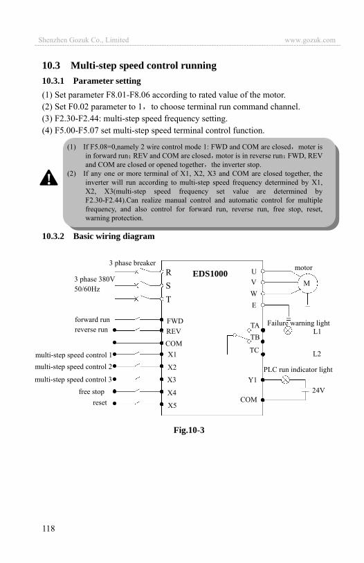
118
10.3 Multi-step speed control running 10.3.1 Parameter setting (1) Set parameter F8.01-F8.06 according to rated value of the motor. (2) Set F0.02 parameter to 1 to choose terminal run command channel. (3) F2.30-F2.44: multi-step speed frequency setting. (4) F5.00-F5.07 set multi-step speed terminal control function.
10.3.2 Basic wiring diagram
Fig.10-3
multi-step speed control 2
ST
FWD
COM
TA
TC
MU
E
motor
WV
TBREV
X1
X5
Y1
COM
R
forward run reverse run
multi-step speed control 1
X2
X3free stop X4
L2
Failure warning light L1
24V
PLC run indicator light
reset
multi-step speed control 3
3 phase breaker EDS1000
3 phase 380V 50/60Hz
(1) If F5.08=0,namely 2 wire control mode 1: FWD and COM are closed moter is in forward run REV and COM are closed motor is in reverse run FWD, REV and COM are closed or opened together the inverter stop.
(2) If any one or more terminal of X1, X2, X3 and COM are closed together, the inverter will run according to multi-step speed frequency determined by X1, X2, X3(multi-step speed frequency set value are determined by F2.30-F2.44).Can realize manual control and automatic control for multiple frequency, and also control for forward run, reverse run, free stop, reset, warning protection.
!
Shenzhen Gozuk Co., Limited www.gozuk.com---------------------------------------------------------------------------------------------------------------------------
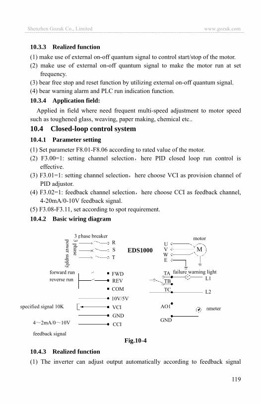
119
10.3.3 Realized function (1) make use of external on-off quantum signal to control start/stop of the motor. (2) make use of external on-off quantum signal to make the motor run at set
frequency. (3) bear free stop and reset function by utilizing external on-off quantum signal. (4) bear warning alarm and PLC run indication function. 10.3.4 Application field:
Applied in field where need frequent multi-speed adjustment to motor speed such as toughened glass, weaving, paper making, chemical etc.. 10.4 Closed-loop control system10.4.1 Parameter setting (1) Set parameter F8.01-F8.06 according to rated value of the motor. (2) F3.00=1: setting channel selection here PID closed loop run control is
effective. (3) F3.01=1: setting channel selection here choose VCI as provision channel of
PID adjustor. (4) F3.02=1: feedback channel selection here choose CCI as feedback channel,
4-20mA/0-10V feedback signal. (5) F3.08-F3.11, set according to spot requirement. 10.4.2 Basic wiring diagram
Fig.10-4
10.4.3 Realized function (1) The inverter can adjust output automatically according to feedback signal
specified signal 10K
4 2mA/0 10V
feedback signal
ammeter
ST
FWD
COM
TA
TC
MU
E
motor
WV
TBREV
10V/5V
GND
AO1
GND
R3 phase breaker
forward run reverse run
CCI
VCI
L2
failure warning lightL1
EDS1000
Shenzhen Gozuk Co., Limited www.gozuk.com---------------------------------------------------------------------------------------------------------------------------
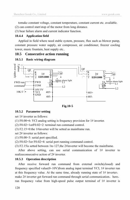
120
tomake constant voltage, constant temperature, constant current etc. available. (2) can control start/stop of the motor from long distance. (3) bear failure alarm and current indicator function. 10.4.4 Application field
Applied in field where need stable system, pressure, flux such as blower pump, constant pressure water supply, air compressor, air conditioner, freezer cooling tower, music fountain, heat supply etc.. 10.5 Consecutive action running10.5.1 Basic wiring diagram
Fig.10-5
10.5.2 Parameter setting set 1# inverter as follows: (1) F0.00=6: YCI analog setting is frequency provision for 1# inverter. (2) F0.02=1orF0.02=2: terminal run command control. (3) F2.15=0:the 1#inverter will be setted as mainframe run. set 2# inverter as follows: (1) F0.00=3: serial port specified. (2) F0.02=3or F0.02=4: serial port running command control. (3) F2.15is setted between 1to 127,the 2#inverter will become the mainframe.
After above setting, can use serial communication of 1# inverter to realizeconsecutive action of 2# inverter. 10.5.3 Operation description
After receive forward run command from external switch(closed) and frequency specified value(0~10V)from analog input terminal YCI, 1# inverter run at this frequency value. At the same time, already running state of 1# invertermake 2# inverter get forward run command through serial communication hererun frequency value from high-speed pulse output terminal of 1# inverter is
QF
ST
U
EWVR
TA
TC TB
GND
COMFWD run command
M ST
U
EW
R
TA
TCTB L1
L2
failure alarm light
L2
L1
485+
M
10V/5VYCI
FWD
10K
1# 2#
QF
EDS1000 EDS1000
485-
485+
485-
failure alarm light
Shenzhen Gozuk Co., Limited www.gozuk.com---------------------------------------------------------------------------------------------------------------------------
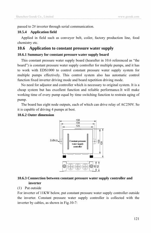
121
passed to 2# inverter through serial communication. 10.5.4 Application field
Applied in field such as conveyer belt, coiler, factory production line, food chemistry etc. 10.6 Application to constant pressure water supply10.6.1 Summary for constant pressure water supply board
This constant pressure water supply board (hearafter in 10.6 referenced as “the board”) is constant pressure water supply controller for multiple pumps, and it has to work with EDS1000 to control constant pressure water supply system for multiple pumps effectively. This control system also has automatic control function fixed inverter driving mode and board repetition driving mode.
No need for adjustor and controller which is necessary to original system. It is a cheap system but has excellent function and reliable performance.It will make working time of every pump equal by time switching function to restrain aging of pump.
The board has eight node outputs, each of which can drive relay of AC250V. So it is capable of driving 4 pumps at best. 10.6.2 Outer dimension
10.6.3 Connection between constant pressure water supply controller and inverter
(1) Put outside For inverter of 11KW below, put constant pressure water supply controller outside the inverter. Constant pressure water supply controller is collected with the inverter by cables, as shown in Fig.10-7:
Shenzhen Gozuk Co., Limited www.gozuk.com---------------------------------------------------------------------------------------------------------------------------
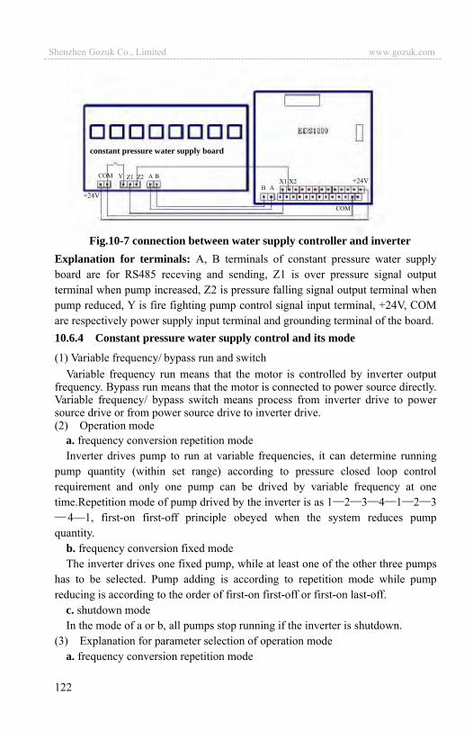
122
+24V
COM Y Z1 Z2 A B
B A X1 X2 +24V
COM
constant pressure water supply board
Fig.10-7 connection between water supply controller and inverter Explanation for terminals: A, B terminals of constant pressure water supply board are for RS485 receving and sending, Z1 is over pressure signal output terminal when pump increased, Z2 is pressure falling signal output terminal when pump reduced, Y is fire fighting pump control signal input terminal, +24V, COM are respectively power supply input terminal and grounding terminal of the board. 10.6.4 Constant pressure water supply control and its mode
(1) Variable frequency/ bypass run and switch Variable frequency run means that the motor is controlled by inverter output
frequency. Bypass run means that the motor is connected to power source directly. Variable frequency/ bypass switch means process from inverter drive to power source drive or from power source drive to inverter drive. (2) Operation mode
a. frequency conversion repetition mode Inverter drives pump to run at variable frequencies, it can determine running
pump quantity (within set range) according to pressure closed loop control requirement and only one pump can be drived by variable frequency at one time.Repetition mode of pump drived by the inverter is as 1 2 3 4 1 2 3
4—1, first-on first-off principle obeyed when the system reduces pump quantity.
b. frequency conversion fixed mode The inverter drives one fixed pump, while at least one of the other three pumps
has to be selected. Pump adding is according to repetition mode while pump reducing is according to the order of first-on first-off or first-on last-off.
c. shutdown mode In the mode of a or b, all pumps stop running if the inverter is shutdown.
(3) Explanation for parameter selection of operation mode a. frequency conversion repetition mode
Shenzhen Gozuk Co., Limited www.gozuk.com---------------------------------------------------------------------------------------------------------------------------

123
If you would like to choose frequency conversion repetition mode, F3.31 must be set to 0. The board control is ineffective if F3.20 is set to 0, while F3.20 is set to other values the board will work according to description of the parameter.
b. frequency conversion fixed mode If you would like to choose frequency conversion fixed mode, F3.31 must be
set to 1 or 2. The board control is ineffective if F3.20 is set to 0, while F3.20 is set to other values the board will work according to description of the parameter. (4) Automatic switch function
Automatic switch function is only effective in frequency conversion repetition mode(F3.31 is 0). The system will switch automatically like pump adding when switch time is up and pumps are in stable running state (no pump adding or reducing). For example, before switch board driving mode is 2G 3G 4B while it is 3G 4G 1B after switch. If drived pump quantity reaches the maximum, automatic switch function is ineffective even though switch time is up. 10.6.5 Function parameter setting for constant pressure water supply
For details of function parameter for constant pressure water supply, please see detailed description of F3 group (Closed-loop run control parameter group) in Chapter 6. Please notice that accelerating or decelerating time can’t be longer than switch judging time for pumps. After wire as the figure, F5.00 must be set to 33 (external interruption input) and F5.01 must be 20 (closed-loop ineffective) in order to avoid water pressure fluctuation when pump adding or reducing. For detailed parameter setting information, please see below table. function
code name set range explanation
F0.08 Acce time 1 Set according to actual situation
F0.09 Dece time 1 Same as above
F0.10 Upper limit freq. Same as above
F0.11 Lower limit freq. Same as above
F3.16 The value of sleep frequency valve Same as above
F3.17 The value of wake pressure valve Same as above
F3.18 The time of delay sleeping time Same as above
F3.19 The time of delay waking time Same as above
F3.20 Constant pressure water supply mode 1 selection
0:inverter works in one-drive-two water supply mode
1:constant pressure water supply board acts in one-drive-two mode
2:constant pressure water supply board acts in one-drive-three
This parameter needs to work with F3.31 to make constant pressure water supply control effective ( for details please see description in 10.6.4)
Shenzhen Gozuk Co., Limited www.gozuk.com---------------------------------------------------------------------------------------------------------------------------
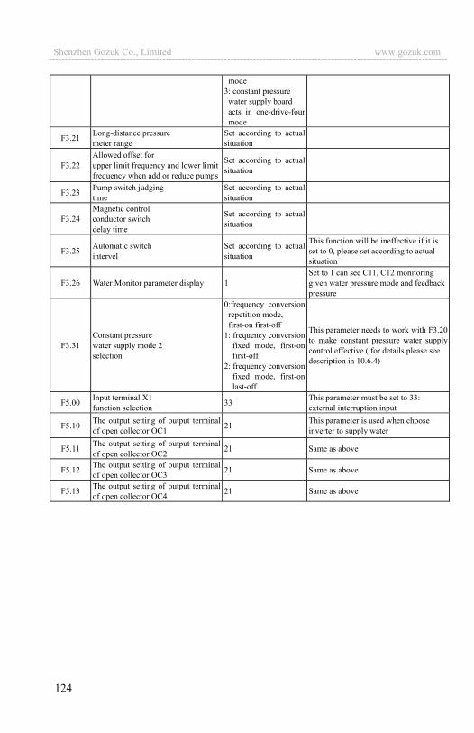
124
mode 3: constant pressure water supply board acts in one-drive-four mode
F3.21 Long-distance pressure meter range
Set according to actual situation
F3.22 Allowed offset for upper limit frequency and lower limit frequency when add or reduce pumps
Set according to actual situation
F3.23 Pump switch judging time
Set according to actual situation
F3.24 Magnetic control conductor switch delay time
Set according to actual situation
F3.25 Automatic switch intervel
Set according to actual situation
This function will be ineffective if it is set to 0, please set according to actual situation
F3.26 Water Monitor parameter display 1 Set to 1 can see C11, C12 monitoring given water pressure mode and feedback pressure
F3.31 Constant pressure water supply mode 2 selection
0:frequency conversion repetition mode, first-on first-off
1: frequency conversion fixed mode, first-on first-off
2: frequency conversion fixed mode, first-on last-off
This parameter needs to work with F3.20 to make constant pressure water supply control effective ( for details please see description in 10.6.4)
F5.00 Input terminal X1 function selection 33 This parameter must be set to 33:
external interruption input
F5.10 The output setting of output terminal of open collector OC1 21 This parameter is used when choose
inverter to supply water
F5.11 The output setting of output terminal of open collector OC2 21 Same as above
F5.12 The output setting of output terminal of open collector OC3 21 Same as above
F5.13 The output setting of output terminal of open collector OC4 21 Same as above
Shenzhen Gozuk Co., Limited www.gozuk.com---------------------------------------------------------------------------------------------------------------------------
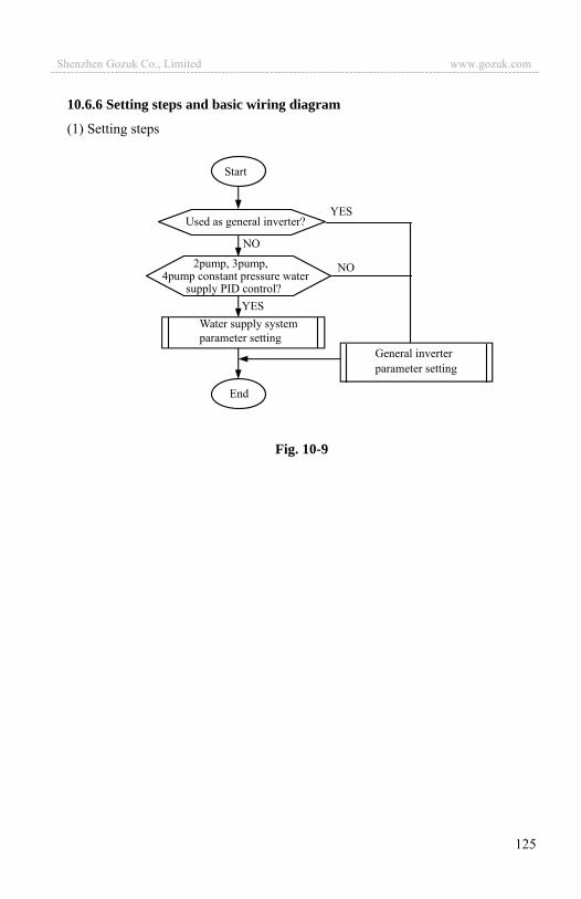
125
10.6.6 Setting steps and basic wiring diagram
(1) Setting steps
Fig. 10-9
Start
YES
NO
YES
NO
Used as general inverter?
2pump, 3pump, 4pump constant pressure water
supply PID control?
End
General inverter parameter setting
Water supply system parameter setting
Shenzhen Gozuk Co., Limited www.gozuk.com---------------------------------------------------------------------------------------------------------------------------
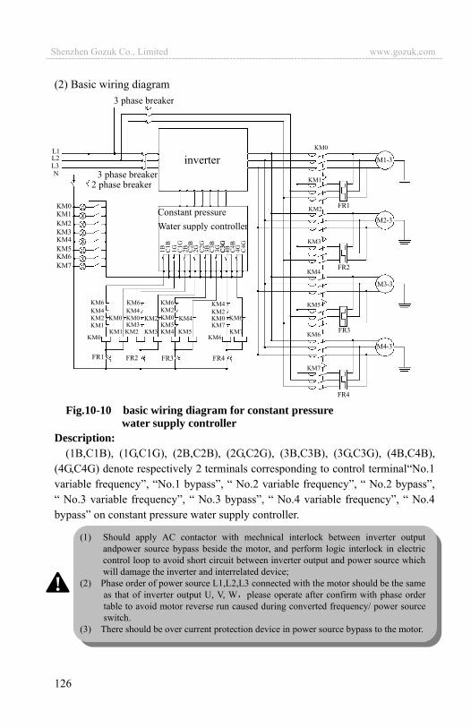
126
(2) Basic wiring diagram
Fig.10-10 basic wiring diagram for constant pressure water supply controller
Description: (1B,C1B), (1G,C1G), (2B,C2B), (2G,C2G), (3B,C3B), (3G,C3G), (4B,C4B),
(4G,C4G) denote respectively 2 terminals corresponding to control terminal“No.1 variable frequency”, “No.1 bypass”, “ No.2 variable frequency”, “ No.2 bypass”, “ No.3 variable frequency”, “ No.3 bypass”, “ No.4 variable frequency”, “ No.4 bypass” on constant pressure water supply controller.
KM0 KM1 KM2 KM3 KM4 KM5 KM6 KM7
KM7 KM6
KM5 KM4 KM3 KM2 KM1 KM0
FR1 FR2 FR3 FR4
KM6 KM4 KM2 KM1
KM6 KM4 KM0 KM3
KM0 KM2
KM6 KM2 KM0 KM5
KM4
KM4 KM2 KM0 KM7
KM6
KM0
KM1
KM2
KM3
KM4
KM5
KM6
KM7
FR1
FR2
FR3
FR4
M4-3
M1-3
M2-3
M3-3
3 phase breaker
3 phase breaker2 phase breaker
L1L2L3N
inverter
Constant pressure Water supply controller
(1) Should apply AC contactor with mechnical interlock between inverter output andpower source bypass beside the motor, and perform logic interlock in electric control loop to avoid short circuit between inverter output and power source which will damage the inverter and interrelated device;
(2) Phase order of power source L1,L2,L3 connected with the motor should be the same as that of inverter output U, V, W please operate after confirm with phase order table to avoid motor reverse run caused during converted frequency/ power source switch.
(3) There should be over current protection device in power source bypass to the motor.
!
Shenzhen Gozuk Co., Limited www.gozuk.com---------------------------------------------------------------------------------------------------------------------------
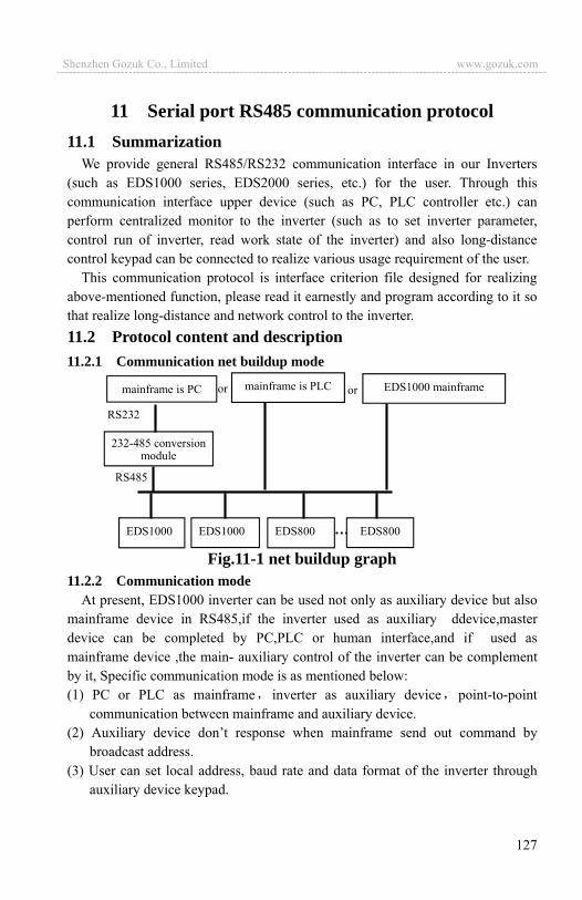
127
11 Serial port RS485 communication protocol 11.1 Summarization
We provide general RS485/RS232 communication interface in our Inverters (such as EDS1000 series, EDS2000 series, etc.) for the user. Through this communication interface upper device (such as PC, PLC controller etc.) can perform centralized monitor to the inverter (such as to set inverter parameter, control run of inverter, read work state of the inverter) and also long-distance control keypad can be connected to realize various usage requirement of the user.
This communication protocol is interface criterion file designed for realizing above-mentioned function, please read it earnestly and program according to it so that realize long-distance and network control to the inverter. 11.2 Protocol content and description 11.2.1 Communication net buildup mode
Fig.11-1 net buildup graph 11.2.2 Communication mode
At present, EDS1000 inverter can be used not only as auxiliary device but also mainframe device in RS485,if the inverter used as auxiliary ddevice,master device can be completed by PC,PLC or human interface,and if used as mainframe device ,the main- auxiliary control of the inverter can be complement by it, Specific communication mode is as mentioned below: (1) PC or PLC as mainframe inverter as auxiliary device point-to-point
communication between mainframe and auxiliary device. (2) Auxiliary device don’t response when mainframe send out command by
broadcast address. (3) User can set local address, baud rate and data format of the inverter through
auxiliary device keypad.
EDS1000 mainframe mainframe is PC mainframe is PLC
232-485 conversionmodule
EDS1000 EDS1000 EDS800 EDS800
or
RS232
RS485
or
Shenzhen Gozuk Co., Limited www.gozuk.com---------------------------------------------------------------------------------------------------------------------------
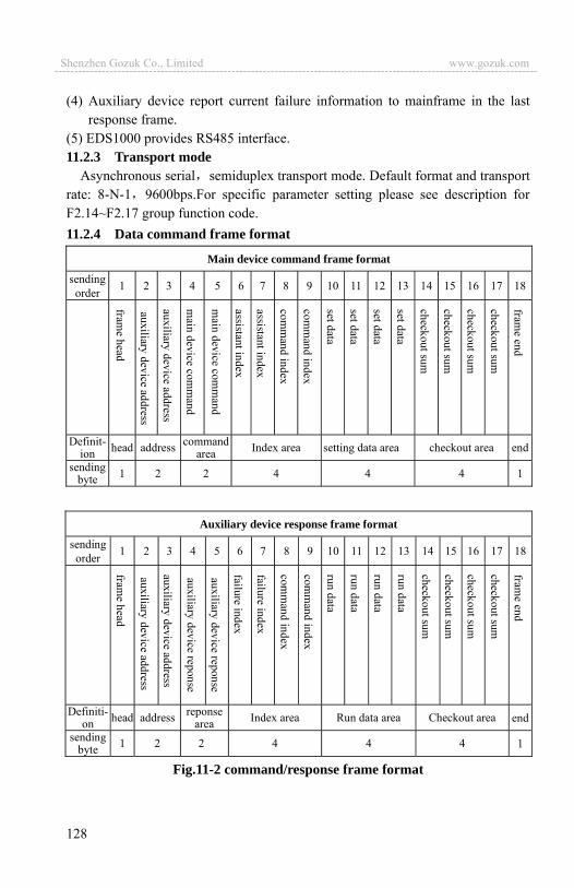
128
(4) Auxiliary device report current failure information to mainframe in the last response frame.
(5) EDS1000 provides RS485 interface. 11.2.3 Transport mode
Asynchronous serial semiduplex transport mode. Default format and transport rate: 8-N-1 9600bps.For specific parameter setting please see description for F2.14~F2.17 group function code.11.2.4 Data command frame format
Main device command frame format
sending order 1 2 3 4 5 6 7 8 9 10 11 12 13 14 15 16 17 18
Definit-ion head address command
area Index area setting data area checkout area end
sending byte 1 2 2 4 4 4 1
Auxiliary device response frame format
sending order 1 2 3 4 5 6 7 8 9 10 11 12 13 14 15 16 17 18
Definiti-on head address reponse
area Index area Run data area Checkout area end
sending byte 1 2 2 4 4 4 1
Fig.11-2 command/response frame format
Shenzhen Gozuk Co., Limited www.gozuk.com---------------------------------------------------------------------------------------------------------------------------

129
Remark:(1) “Setting data area” and “run data area” may not be existent in some
command/data frame format, so in protocol command list it’s marked with “nothing”.
(2) In protocol effective character set is: ~, 1, 2, 3, 4, 5, 6, 7, 8, 9, A, B, C, D, E, F and hex data 0DH ASCII lowercase a, b, c, d, e, f are invalid.
(3) Effective command frame length is 14 or 18 byte. 11.2.5 Explanation and description for format(1) frame head
It’s character ~ (namely hex 7E),single byte. (2) auxiliary device address
Data meanings: local address of auxiliary device, double byte. ASCII format. Inverter factory default is 01. (3) mainframe command/auxiliary device respond
Data meanings: mainframe send out command and auxiliary device respond to the command. Double byte, ASCII format.
Response code function classification: Species 1>: command code= 10 mainframe ask auxiliary device to report current preparation state and control situation.
Table 11-1 response code meanings for command code 10
Response code
ASCII
Meanings Preparation state of auxiliary device
Control from mainframe is allowed
To set frequency is allowed
10 Don’t get ready No meaning
11 Get ready Allow Allow
12 Get ready Allow Allow
13 Get ready Don’t allow Don’t allow
14 Get ready Don’t allow Don’t allow
20 Frame error
Species 2>: command code= 11 ~ 15 , 5 kinds of function command which mainframe send to auxiliary device, for detail please see protocol command list.
Table 11-2 response code meanings for command code “11~15” response
code ASCII
Meanings of response code description
00
Auxiliary device communication and control is normal function code modification is effectivepassword is correct.
20 (1) frame checkout error When this response code is reported,
Shenzhen Gozuk Co., Limited www.gozuk.com---------------------------------------------------------------------------------------------------------------------------
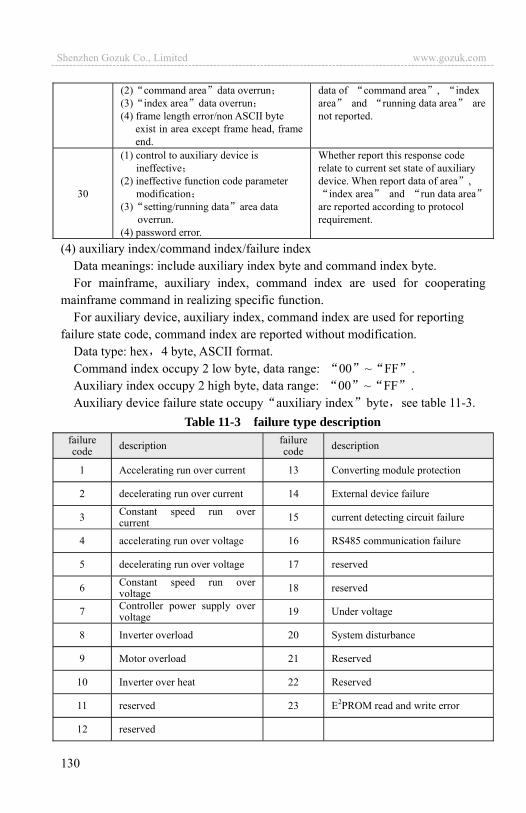
130
(2) command area data overrun(3) index area data overrun(4) frame length error/non ASCII byte
exist in area except frame head, frame end.
data of command area , index area and running data area arenot reported.
30
(1) control to auxiliary device is ineffective
(2) ineffective function code parameter modification
(3) setting/running data area data overrun.
(4) password error.
Whether report this response code relate to current set state of auxiliary device. When report data of area ,
index area and run data areaare reported according to protocol requirement.
(4) auxiliary index/command index/failure indexData meanings: include auxiliary index byte and command index byte. For mainframe, auxiliary index, command index are used for cooperating
mainframe command in realizing specific function. For auxiliary device, auxiliary index, command index are used for reporting
failure state code, command index are reported without modification. Data type: hex 4 byte, ASCII format. Command index occupy 2 low byte, data range: 00 ~ FF .Auxiliary index occupy 2 high byte, data range: 00 ~ FF .Auxiliary device failure state occupy auxiliary index byte see table 11-3.
Table 11-3 failure type description failure code description failure
code description
1 Accelerating run over current 13 Converting module protection
2 decelerating run over current 14 External device failure
3 Constant speed run over current 15 current detecting circuit failure
4 accelerating run over voltage 16 RS485 communication failure
5 decelerating run over voltage 17 reserved
6 Constant speed run over voltage 18 reserved
7 Controller power supply over voltage 19 Under voltage
8 Inverter overload 20 System disturbance
9 Motor overload 21 Reserved
10 Inverter over heat 22 Reserved
11 reserved 23 E2PROM read and write error
12 reserved
Shenzhen Gozuk Co., Limited www.gozuk.com---------------------------------------------------------------------------------------------------------------------------
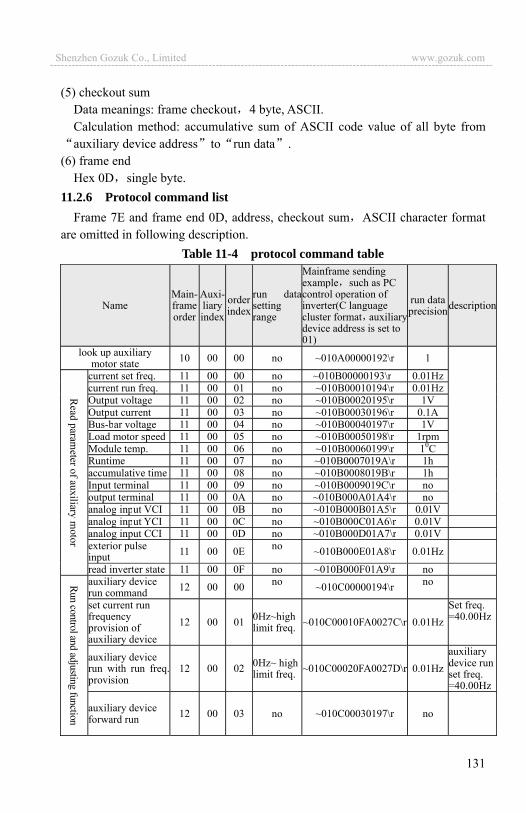
131
(5) checkout sum Data meanings: frame checkout 4 byte, ASCII. Calculation method: accumulative sum of ASCII code value of all byte fromauxiliary device address to run data .
(6) frame end Hex 0D single byte.
11.2.6 Protocol command list Frame 7E and frame end 0D, address, checkout sum ASCII character format
are omitted in following description. Table 11-4 protocol command table
Name Main-frame order
Auxi-liaryindex
orderindex
run datasetting range
Mainframe sending example such as PC control operation of inverter(C language cluster format auxiliarydevice address is set to01)
run data precisiondescription
look up auxiliary motor state 10 00 00 no ~010A00000192\r 1
current set freq. 11 00 00 no ~010B00000193\r 0.01Hzcurrent run freq. 11 00 01 no ~010B00010194\r 0.01HzOutput voltage 11 00 02 no ~010B00020195\r 1VOutput current 11 00 03 no ~010B00030196\r 0.1ABus-bar voltage 11 00 04 no ~010B00040197\r 1VLoad motor speed 11 00 05 no ~010B00050198\r 1rpmModule temp. 11 00 06 no ~010B00060199\r 10CRuntime 11 00 07 no ~010B0007019A\r 1haccumulative time 11 00 08 no ~010B0008019B\r 1hInput terminal 11 00 09 no ~010B0009019C\r nooutput terminal 11 00 0A no ~010B000A01A4\r noanalog input VCI 11 00 0B no ~010B000B01A5\r 0.01Vanalog input YCI 11 00 0C no ~010B000C01A6\r 0.01Vanalog input CCI 11 00 0D no ~010B000D01A7\r 0.01Vexterior pulse input 11 00 0E no ~010B000E01A8\r 0.01Hz
read inverter state 11 00 0F no ~010B000F01A9\r noauxiliary device run command 12 00 00 no ~010C00000194\r no
set current run frequency provision of auxiliary device
12 00 01 0Hz~highlimit freq. ~010C00010FA0027C\r 0.01Hz
Set freq.=40.00Hz
auxiliary device run with run freq.provision
12 00 02 0Hz~ highlimit freq. ~010C00020FA0027D\r 0.01Hz
auxiliary device run set freq. =40.00Hz
auxiliary device forward run 12 00 03 no ~010C00030197\r no
Shenzhen Gozuk Co., Limited www.gozuk.com---------------------------------------------------------------------------------------------------------------------------
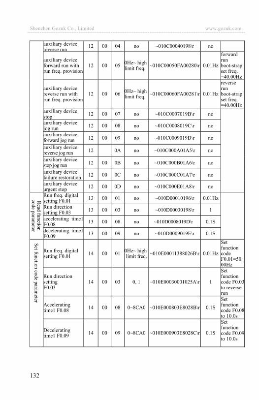
132
auxiliary device reverse run 12 00 04 no ~010C00040198\r no
auxiliary device forward run with run freq. provision
12 00 05 0Hz~ highlimit freq. ~010C00050FA00280\r 0.01Hz
forward runboot-strap set freq. =40.00Hz
auxiliary device reverse run with run freq. provision
12 00 06 0Hz~ highlimit freq. ~010C00060FA00281\r 0.01Hz
reverserunboot-strap set freq. =40.00Hz
auxiliary device stop 12 00 07 no ~010C0007019B\r no
auxiliary device jog run 12 00 08 no ~010C0008019C\r no
auxiliary device forward jog run 12 00 09 no ~010C0009019D\r no
auxiliary device reverse jog run 12 0A no ~010C000A01A5\r no
auxiliary device stop jog run 12 00 0B no ~010C000B01A6\r no
auxiliary device failure restoration 12 00 0C no ~010C000C01A7\r no
auxiliary device urgent stop 12 00 0D no ~010C000E01A8\r no
Run freq. digital setting F0.01 13 00 01 no ~010D00010196\r 0.01Hz
Run direction setting F0.03 13 00 03 no ~010D00030198\r 1
accelerating time1F0.08 13 00 08 no ~010D0008019D\r 0.1S
decelerating time1F0.09 13 00 09 no ~010D0009019E\r 0.1S
Run freq. digital setting F0.01 14 00 01 0Hz~ high
limit freq. ~010E00011388026B\r 0.01Hz
Set function code F0.01=50.00Hz
Run direction setting F0.03
14 00 03 0, 1 ~010E00030001025A\r 1
Set function code F0.03 to reverserun
Accelerating time1 F0.08 14 00 08 0~8CA0 ~010E000803E8028B\r 0.1S
Set function code F0.08 to 10.0s
Decelerating time1 F0.09 14 00 09 0~8CA0 ~010E000903E8028C\r 0.1S
Set function code F0.09 to 10.0s
Shenzhen Gozuk Co., Limited www.gozuk.com---------------------------------------------------------------------------------------------------------------------------
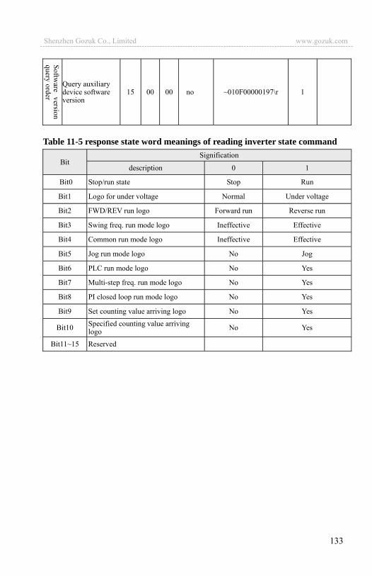
133
Query auxiliary device software version
15 00 00 no ~010F00000197\r 1
Table 11-5 response state word meanings of reading inverter state command
Bit Signification
description 0 1
Bit0 Stop/run state Stop Run
Bit1 Logo for under voltage Normal Under voltage
Bit2 FWD/REV run logo Forward run Reverse run
Bit3 Swing freq. run mode logo Ineffective Effective
Bit4 Common run mode logo Ineffective Effective
Bit5 Jog run mode logo No Jog
Bit6 PLC run mode logo No Yes
Bit7 Multi-step freq. run mode logo No Yes
Bit8 PI closed loop run mode logo No Yes
Bit9 Set counting value arriving logo No Yes
Bit10 Specified counting value arriving logo No Yes
Bit11~15 Reserved
Shenzhen Gozuk Co., Limited www.gozuk.com---------------------------------------------------------------------------------------------------------------------------
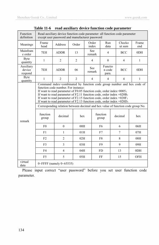
134
Table 11-6 read auxiliary device function code parameter Function definition
Read auxiliary device function code parameter: all function code parameter except user password and manufacturer password
Meanings Frame head Address Order Order
index Run data
Checkout sum
Frame end
Mainframe order 7EH ADDR 13 See
remark 4 BCC 0DH
Byte quantity 1 2 2 4 0 4 1
Auxiliary device
respond 7EH ADDR 06 See
remark Function code para.
BCC 0DH
Byte quantity 1 2 2 4 4 4 1
remark
Command index=combinated by function code group number and hex code of function code number. For instance: If want to read parameter of F0.05 function code, order index=0005If want to read parameter of F2.11 function code, order index =020BIf want to read parameter of F2.15 function code, order index =020FIf want to read parameter of F2.13 function code, order index =020DCorresponding relation between decimal and hex value of function code group No.
function group decimal hex function
group decimal hex
F0 0 00H F6 6 06H
F1 1 01H F7 7 07H
F2 2 02H F8 8 08H
F3 3 03H F9 9 09H
F4 4 04H FD 13 0DH
F5 5 05H FF 15 OFH virtual data 0~FFFF (namely 0~65535)
Please input correct “user password” before you set user function code parameter.
Shenzhen Gozuk Co., Limited www.gozuk.com---------------------------------------------------------------------------------------------------------------------------
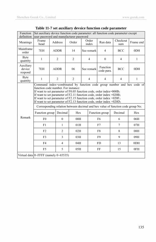
135
Table 11-7 set auxiliary devsice function code parameter Function definition
Set auxiliary device function code parameter: all function code parameter exceptuser password and manufacturer password
Meanings Frame head Address Order Order
index Run data Checkout sum Frame end
Mainframe order 7EH ADDR 14 See remark 4 BCC 0DH
Byte quantity 1 2 2 4 0 4 1
Auxiliary device
respond 7EH ADDR 06 See remark Function
code para. BCC 0DH
Byte quantity 1 2 2 4 4 4 1
Remark
Command index=combinated by function code group number and hex code of function code number. For instance: If want to set parameter of F0.05 function code, order index=000BIf want to set parameter of F2.11 function code, order index =020BIf want to set parameter of F2.15 function code, order index =020FIf want to set parameter of F2.13 function code, order index =020D
Corresponding relation between decimal and hex value of function code group No.
Function group Decimal Hex Function group Decimal Hex
F0 0 00H F6 6 06H
F1 1 01H F7 7 07H
F2 2 02H F8 8 08H
F3 3 03H F9 9 09H
F4 4 04H FD 13 0DH
F5 5 05H FF 15 0FH
Virtual data 0~FFFF (namely 0~65535)
Shenzhen Gozuk Co., Limited www.gozuk.com---------------------------------------------------------------------------------------------------------------------------
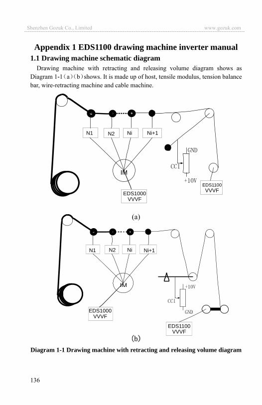
136
Appendix 1 EDS1100 drawing machine inverter manual 1.1 Drawing machine schematic diagram
Drawing machine with retracting and releasing volume diagram shows as Diagram 1-1 a b shows. It is made up of host, tensile modulus, tension balance bar, wire-retracting machine and cable machine.
(a)
Diagram 1-1 Drawing machine with retracting and releasing volume diagram
IM
EDS1000VVVF
EDS1100VVVF
N1 N2 Ni Ni+1
IM
EDS1000VVVF
EDS1100VVVF
N1 N2 Ni Ni+1
Shenzhen Gozuk Co., Limited www.gozuk.com---------------------------------------------------------------------------------------------------------------------------

137
2.1 Working Theory 2.1.1 Working Theory
To ensure the drawing machine keep constant tension in the process of receiving and releasing line and continue to line up line synchronously, especially for Micro-pulling machine, we generally take frequency output voltage signal of host as analog input voltage signal of wire retracting machine. The output frequency of wire retracting machine should be reduced gradually so as to make retracting and releasing wire in the same step with the increasing of wire retracting machine volume diameter, and the output frequency of wire-retracting machine is inversely proportional to volume diameter.
If we set the liner speed of retractable wire and releasable wire as V, and following:
V=i* *R=2 F*R= *i*F*D F=i*V/ *D F refers to output frequency of wire retracting machine, i refers to machinery rotation ratio of retractable wire and releasable wire, V refers to liner speed of host, which is proportional to the output frequency of
host. F is inversely proportional to the volume diameter of wire-retracting drum which indicated as D.
The output frequency of EDS1100 Series inverter is: F=i*V/ *D+K2*UPID
We define K1=i/ *D which called coil coefficient. D0 means empty diameter of wire-retracting coil, when the coil diameter
restores, K1 there means empty path coefficients.K1 is F2.22 and K2 is F2.23. 2.1.2 Working requirements
(1) Jog lead wire must be independent (2) Host operates with slow acceleration and deceleration (3) Smoothly start up with continuous line (4) Steady operation with small swing (5) Synchronous machine stop without hitting limit down.
2.1.3 Feedback polarity detection After EDS1100 inverter connects with tension balance bar voltage feedback as
diagram 1-1 shows, then move tension balance bar as it swings when wire-retracting machine retracts wire. In the mean while, you should monitor PID feedback voltage C.12 (to revise F3.28=12, so the panel monitor parameter is PID feedback voltage), the value should change from low to high, generally change in the range of 0.00V~10.00V or 2.00V~8.00V. If the value is not in this range, the
Shenzhen Gozuk Co., Limited www.gozuk.com---------------------------------------------------------------------------------------------------------------------------
138
position of tension potentiometer should be changed to make the central point as about 5.00V.This tension potentiometer should be the high-accuracy one with 360°. 2.1.4 Jog lead wire
The frequency of host jog lead wire and time of acceleration and deceleration are independent from the ones at normal work. Jog frequency is multi-section speed 2 F2.06 generally at about 6.0Hz. Jog acceleration and deceleration time
F2.07 and F2.08 is generally about 10.0S. 2.1.5 Maximum frequency
As the frequency output of host is provision linear speed of retractable and releasable wire, in order to ensure the liner relation between host frequency and wire-retracting machine frequency, we have to equate the maximum frequency between them. The high limit frequency of wire-retracting machine is just the maximum frequency of itself.
Maximum working frequency of host is decided by the maximum liner speed of drawing machine. Assuming we indicate the output frequency of host with highest linear speed as F0 and ratio between full-diameter and empty-diameter of wire-retracting machine as N=D1/D0 (N is generally 1.2~1.8). Mechanical transmission ratio between wire-retracting machine and host is i (i is usually about 1).Then the following:
FN/FF=N FN indicates output frequency of wire retracting machine empty- diameter FF indicates output frequency of wire retracting machine full-diameter. (FN+ FF)/2=i*F0 FN=N/(N+1)*2*i*F0 Maximum frequency of host and wire retracting machine is: FMAX=MAX FN F0 Suppose we set i=1 N=1.8 F0=70.0Hz,we can get FN=90.0Hz FF=50.0Hz. So the maximum frequency of host FMAX=90.0Hz, and the upper limit frequency F0=70.0Hz. And the maximum frequency of wire receiving machine FMAX=90.0Hz, and The upper limit frequency FMAX=90.0Hz.
2.1.6 Smoothly start up for wire retracting machine The wire retracting machine is generally in the machinery low limit position,
while not in zero position of tension sway bar. The PID adjustment makes a certain amount provision input frequency for wire receiving machine when host frequency is at 0Hz, which will cause impact when wire retracting machine starts up if haven�t made any relevant disposal, as to fine-drawing machine and
Shenzhen Gozuk Co., Limited www.gozuk.com---------------------------------------------------------------------------------------------------------------------------
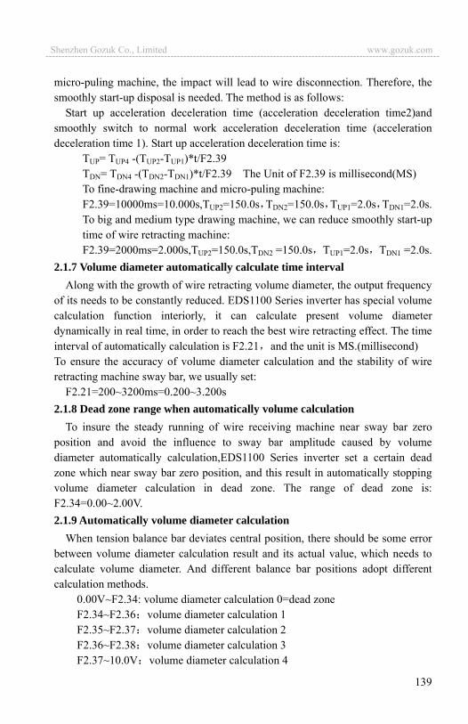
139
micro-puling machine, the impact will lead to wire disconnection. Therefore, the smoothly start-up disposal is needed. The method is as follows:
Start up acceleration deceleration time (acceleration deceleration time2)and smoothly switch to normal work acceleration deceleration time (acceleration deceleration time 1). Start up acceleration deceleration time is:
TUP= TUP4 -(TUP2-TUP1)*t/F2.39 TDN= TDN4 -(TDN2-TDN1)*t/F2.39 The Unit of F2.39 is millisecond(MS) To fine-drawing machine and micro-puling machine: F2.39=10000ms=10.000s,TUP2=150.0s TDN2=150.0s TUP1=2.0s TDN1=2.0s.
To big and medium type drawing machine, we can reduce smoothly start-up time of wire retracting machine: F2.39=2000ms=2.000s,TUP2=150.0s,TDN2 =150.0s TUP1=2.0s TDN1 =2.0s.
2.1.7 Volume diameter automatically calculate time interval Along with the growth of wire retracting volume diameter, the output frequency
of its needs to be constantly reduced. EDS1100 Series inverter has special volume calculation function interiorly, it can calculate present volume diameter dynamically in real time, in order to reach the best wire retracting effect. The time interval of automatically calculation is F2.21 and the unit is MS.(millisecond) To ensure the accuracy of volume diameter calculation and the stability of wire retracting machine sway bar, we usually set:
F2.21=200~3200ms=0.200~3.200s 2.1.8 Dead zone range when automatically volume calculation
To insure the steady running of wire receiving machine near sway bar zero position and avoid the influence to sway bar amplitude caused by volume diameter automatically calculation,EDS1100 Series inverter set a certain dead zone which near sway bar zero position, and this result in automatically stopping volume diameter calculation in dead zone. The range of dead zone is: F2.34=0.00~2.00V. 2.1.9 Automatically volume diameter calculation
When tension balance bar deviates central position, there should be some error between volume diameter calculation result and its actual value, which needs to calculate volume diameter. And different balance bar positions adopt different calculation methods.
0.00V~F2.34: volume diameter calculation 0=dead zone F2.34~F2.36 volume diameter calculation 1 F2.35~F2.37 volume diameter calculation 2 F2.36~F2.38 volume diameter calculation 3 F2.37~10.0V volume diameter calculation 4
Shenzhen Gozuk Co., Limited www.gozuk.com---------------------------------------------------------------------------------------------------------------------------

140
2.1.10 Volume diameter reset When with empty diameter, the output frequency of wire retracting machine
indicates as FN. And when with full diameter, the output frequency of wire retracting machine indicates as FF.
The output frequency with full diameter and empty diameter of wire retracting machine is different greatly, in order to make the liner speed of wire retracting machine and host in the same step as soon as possible, the volume diameter reset is needed when wire retracting machine changes volume. And the external terminal X6 should set as 39, this terminal is defined volume reset terminal with EDS1100 Series inverter. 2.1.11 Drawing machine tension control
F3.00=1 EDS1100 Series inverter is drawing machine tension control mode. 2.1.12 Control wiring (1) Connect Jog switch with host X2(defined as jog). (2) Connect external terminal start-up switch with host FWD terminal. (3)Connect pull wire speed potentiometer with host machine+10V VCI and
GND. (4) Connect host analog output A02 terminal and GND terminal with VCI
terminal and GND terminal of wire retracting machine. (5) Connect tension bar potentiometer with +10V, CCI and GND terminals of
EDS1100 Series inverter. (6) Other relative control signal. 3.1 EDS1100 Series inverter model No. and specification
EDS1100 Series inverter rated input power: 3 phase AC 380V; Adaptable electric motor power range is 0.75~37kW; Max.output voltage is the same as input voltage . EDS1100 Series inverter model No. and rated output current show as attached
list 1-1: Attached list 1-1 EDS1100 Series drawing machine inverter model No.
Model No. Adaptable Motor Rated power(kW)
Adaptable Motor Rated voltage(V)
Rated output current (A)
EDS1100-4T0007 0.75
3 Phase AC 380V
2.3
EDS1100-4T0015 1.5 3.7
EDS1100-4T0022 2.2 5.0
EDS1100-4T0037 3.7 8.5
EDS1100-4T0055 5.5 13
Shenzhen Gozuk Co., Limited www.gozuk.com---------------------------------------------------------------------------------------------------------------------------
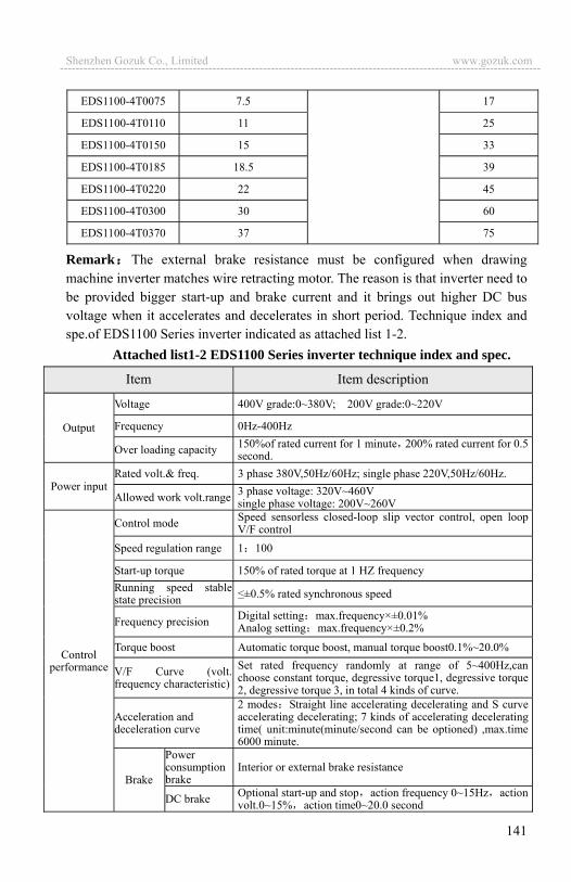
141
EDS1100-4T0075 7.5 17
EDS1100-4T0110 11 25
EDS1100-4T0150 15 33
EDS1100-4T0185 18.5 39
EDS1100-4T0220 22 45
EDS1100-4T0300 30 60
EDS1100-4T0370 37 75
Remark The external brake resistance must be configured when drawing machine inverter matches wire retracting motor. The reason is that inverter need to be provided bigger start-up and brake current and it brings out higher DC bus voltage when it accelerates and decelerates in short period. Technique index and spe.of EDS1100 Series inverter indicated as attached list 1-2.
Attached list1-2 EDS1100 Series inverter technique index and spec.
Item Item description
Output
Voltage 400V grade:0~380V; 200V grade:0~220V
Frequency 0Hz-400Hz
Over loading capacity 150%of rated current for 1 minute 200% rated current for 0.5 second.
Power input Rated volt.& freq. 3 phase 380V,50Hz/60Hz; single phase 220V,50Hz/60Hz.
Allowed work volt.range 3 phase voltage: 320V~460V single phase voltage: 200V~260V
Control performance
Control mode Speed sensorless closed-loop slip vector control, open loop V/F control
Speed regulation range 1 100
Start-up torque 150% of rated torque at 1 HZ frequency Running speed stable state precision ±0.5% rated synchronous speed
Frequency precision Digital setting max.frequency×±0.01% Analog setting max.frequency×±0.2%
Torque boost Automatic torque boost, manual torque boost0.1%~20.0%
V/F Curve (volt. frequency characteristic)
Set rated frequency randomly at range of 5~400Hz,can choose constant torque, degressive torque1, degressive torque 2, degressive torque 3, in total 4 kinds of curve.
Acceleration and deceleration curve
2 modes Straight line accelerating decelerating and S curve accelerating decelerating; 7 kinds of accelerating decelerating time( unit:minute(minute/second can be optioned) ,max.time 6000 minute.
Brake
Power consumption brake
Interior or external brake resistance
DC brake Optional start-up and stop action frequency 0~15Hz action volt.0~15% action time0~20.0 second
Shenzhen Gozuk Co., Limited www.gozuk.com---------------------------------------------------------------------------------------------------------------------------
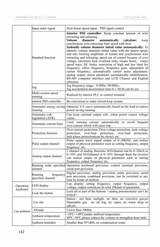
142
Input order signal Host linear speed input PID signal control
Standard function
Interior PID controller: Keep constant tension of wire retracting and releasing . Volume diameter automatically calculate: keep synchronous wire retracting liner speed with host. Indentify volume diameter initial value automatically: To identify volume diameter initial value with the fastest speed, and also limiting amplitude of instant and synchronous wire retracting and releasing, speed out of control because of over voltage, electronic heat overload relay, torque boost, rotary speed trace, DC brake, restriction of high and low limit for frequency, offset frequency, frequency gain, adjustment of carrier frequency, automatically carrier noise adjustment, analog output, motor parameter automatically identification, RS-485 computer interface and LCD Chinese and English selection.
Jog Jog frequency range 0.50Hz~50.00HzJog acceleration deceleration time 0.1~60.0s can be set
Multi-section speed running Realized by interior PLC or control terminal
interior PID controller Be convenient to make closed-loop system Automatic energy saving running
Optimize V/F curve automatically based on the load to realize power saving running
Automatic volt. regulation (AVR)
Can keep constant output volt., when power source voltage varies.
Automatic current limit Limit running current automatically to avoid frequent over-current which will cause trip.
Protection function Over-current protection, Over-voltage protection lack-voltage protection, over-heat protection, over-load protection, lack-phase protection(can be chose), etc.
Pulse output channel Pulse square wave signal output of 0~20KHZ, can realize output of physical parameter such as setting frequency, output frequency ,etc.
Analog output channel 2 channel of analog, thereinto AO1channel can be 4~20mA or 0~10V, and AO2channel is 0~10V; through them the inverter can realize output of physical parameter such as setting frequency, output frequency etc.
Running order specified channel
Operation keyboard provision, control terminal provision, serial port provision.
Running frequency specified channel
Digital provision, analog provision, pulse provision, serial port provision, combined provision, can be switched at any time by kinds of method.
Operation keyboard
LED display Can display setting frequency, output frequency, output voltage, output current,etc.In total 20kinds of parameter.
Lock the button Lock all or part of the buttons analog potentiometer can�t be locked
Use ambient
Use site Indoor not bear sunlight, no dust, no corrosive gas,no flammable gas, no oil fog, no vapor, no water drop or salt,etc.
Altitude Lower than 1000m.
Ambient temperature -10ºC~+40ºC(under ambient temperature40ºC~50ºC,please reduce the volume or strengthen heat sink)
Ambient humidity Smaller than 95%RH, no condensation water
Shenzhen Gozuk Co., Limited www.gozuk.com---------------------------------------------------------------------------------------------------------------------------

143
Vibration Smaller than 5.9m/s2(0.6g)
Storage tempera ion -40ºC~+70ºC
Defending grade IP20
Cooling mode Compel wind cooling By fan with automatic temperature control
Mounting mode Wall hanging
4.1 Function code schedule graph 4.1.1 Function code schedule graph especially for drawing machine
Telecommunication serial No. is the function code address when computer communicates.
F0 Basic run function parameter groupFunction
code Name Parameter setting Unit Factory default
Modification
F0.00 Frequency input channel selection
0 keyboard analog potentiometer setting 1 operation keyboard digital setting 2 terminal UP/DOWN adjust setting frequency(stored
after power off) 3 Serial port setting 4 VCI analog setting VCI-GND 5 CCI analog setting CCI-GND 6 YCI analog setting YCI-GND 7 terminal pulse PULSE frequency setting 8 combination setting 9 terminal UP/DOWN adjust setting frequency(not stored after power off)
1 0
F0.02 Run command channel selection
0 operation keyboard run control 1 terminal run command control(keypad STOP
command ineffective ) 2 terminal run command control(keypad STOP
command effective ) 3 serial port run command control ((keypad STOP
command ineffective) 4 serial port run command control ((keypad STOP
command effective)
1 0
F0.03 Run direction setting
Unit�s digit 0 forward run, 1 reverse run Tens place 0 reverse run allowed
1 reverse run banned 1 00
F0.08 Acce. time 1 0.1 6000.0 0.1 20.0
F0.09 Dece. time 1 0.1 6000.0 0.1 20.0
F0.10 Upper limit freq. Lower limit freq. 400.00Hz 0.01Hz 50.00Hz
F0.14 Torque boost 0.0 20.0(%) 0.1(%) 2.0(%)
Shenzhen Gozuk Co., Limited www.gozuk.com---------------------------------------------------------------------------------------------------------------------------
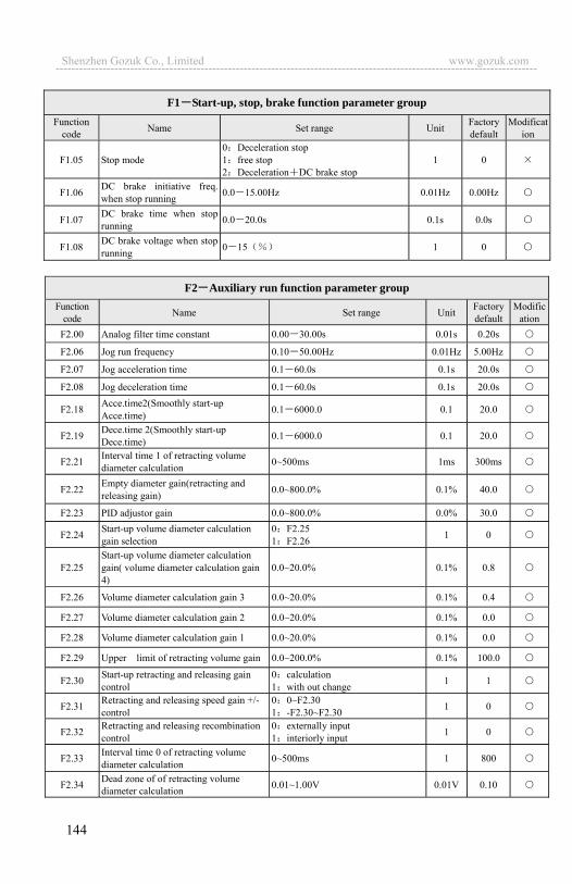
144
F1 Start-up, stop, brake function parameter group Function
code Name Set range Unit Factory default
Modification
F1.05 Stop mode 0 Deceleration stop 1 free stop 2 Deceleration DC brake stop
1 0
F1.06 DC brake initiative freq. when stop running 0.0 15.00Hz 0.01Hz 0.00Hz
F1.07 DC brake time when stop running 0.0 20.0s 0.1s 0.0s
F1.08 DC brake voltage when stop running 0 15 1 0
F2 Auxiliary run function parameter group
Function code Name Set range Unit Factory
defaultModific
ationF2.00 Analog filter time constant 0.00 30.00s 0.01s 0.20s
F2.06 Jog run frequency 0.10 50.00Hz 0.01Hz 5.00Hz
F2.07 Jog acceleration time 0.1 60.0s 0.1s 20.0s
F2.08 Jog deceleration time 0.1 60.0s 0.1s 20.0s
F2.18 Acce.time2(Smoothly start-up Acce.time) 0.1 6000.0 0.1 20.0
F2.19 Dece.time 2(Smoothly start-up Dece.time) 0.1 6000.0 0.1 20.0
F2.21 Interval time 1 of retracting volume diameter calculation 0~500ms 1ms 300ms
F2.22 Empty diameter gain(retracting and releasing gain) 0.0~800.0% 0.1% 40.0
F2.23 PID adjustor gain 0.0~800.0% 0.0% 30.0
F2.24 Start-up volume diameter calculation gain selection
0 F2.25 1 F2.26 1 0
F2.25 Start-up volume diameter calculation gain( volume diameter calculation gain 4)
0.0~20.0% 0.1% 0.8
F2.26 Volume diameter calculation gain 3 0.0~20.0% 0.1% 0.4
F2.27 Volume diameter calculation gain 2 0.0~20.0% 0.1% 0.0
F2.28 Volume diameter calculation gain 1 0.0~20.0% 0.1% 0.0
F2.29 Upper limit of retracting volume gain 0.0~200.0% 0.1% 100.0
F2.30 Start-up retracting and releasing gain control
0 calculation 1 with out change 1 1
F2.31 Retracting and releasing speed gain +/- control
0 0~F2.30 1 -F2.30~F2.30 1 0
F2.32 Retracting and releasing recombination control
0 externally input 1 interiorly input 1 0
F2.33 Interval time 0 of retracting volume diameter calculation 0~500ms 1 800
F2.34 Dead zone of of retracting volume diameter calculation 0.01~1.00V 0.01V 0.10
Shenzhen Gozuk Co., Limited www.gozuk.com---------------------------------------------------------------------------------------------------------------------------
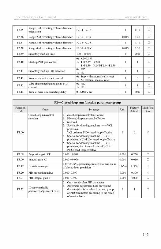
145
F2.35 Range 1 of retracting volume diameter calculation F2.34~F2.36 1 0.70
F2.36 Range 2 of retracting volume diameter F2.35~F2.37 0.01V 1.20
F2.37 Range 3 of retracting volume diameter F2.36~F2.38 1 1.70
F2.38 Range 4 of retracting volume diameter F2.37~5.00V 0.01V 2.20
F2.39 Smoothly start-up time 100~1500ms 1 2000
F2.40 Start-up PID gain control 0 K2=F2.39 1 T<F2.39 K2=0 T>F2.39 K2=T/F2.44*F2.39
1 1
F2.41 Smoothly start-up PID selection 0 PID 1 PD 1 1
F2.42 Volume diameter reset control 0 Stop with automatically reset 1 X6 terminal manual reset 1 0
F2.43 Wire disconnecting and delay PID control
0 PID 1 PD 1 1
F2.44 Time of wire disconnecting delay 0~32000Vms 1 5000
F3 Closed-loop run function parameter group
Function code Name Set range Unit Factory
default Modificat
ion
F3.00
Closed-loop run control selection
0 closed-loop run control ineffective 1 PI closed-loop run control effective 2 reserved 3 Special for drawing machine VCI
provision, VCI ordinary PID closed-loop effective
4 Special for drawing machine VCI provision VCI+PID closed-loop effective
5 Special for drawing machine VCI provision, feed forward control VCIPID closed-loop effective
1 0
F3.08 Proportion gain KP 0.000 9.999 0.001 0.250
F3.09 Integral gain KI 0.000 9.999 0.001 0.010
F3.12 Deviation margin 0.0 20.0(%) percentage relative to max.value of closed-loop provision 0.1(%) 1.0(%)
F3.20 PID proportion gain2 0.000~9.999 0.001 0.300
F3.21 PID integral gain 2 0.000~9.999 0.001 0.000
F3.22 ID Automatically parameter adjustment basis
0 Only use the first PID parameter 1 Automatic adjustment base on volume
diameter(that is to select from two group of PID parameters according to the place of tension bar )
1 1
Shenzhen Gozuk Co., Limited www.gozuk.com---------------------------------------------------------------------------------------------------------------------------

146
F3.30 Failure relay TA,TB,TC function selection
0 inverter running RUN 1 frequency arriving signal FAR 2 frequency level detecting signal FDT13 reserved 4 Over load warning alarm signal OL 5 Output frequency reach high limit
FHL 6 Output frequency reach low limit FLL7 inverter under voltage blockage stop (LU) 8 external failure stop running EXT 9 inverter zero speed running 10 PLC running 11 simple PLC section running finished 12 PLC finish a cycle running 13 reserved 14 inverter ready to run (RDY) 15 inverter malfunction 16 Swing frequency high and low limit
restriction 17 interior counter reach final value 18 interior counter reach specified value 19 set run time arriving 20 interior timing arriving 21 reserved 22 reserved 23 reserved 24 reserved
15
F5 Terminal correlative function parameter group Function
code Name Set range Unit Factory default
Modification
F5.00 Input terminal X1 function selection
31 Run command channel selection 3 32 Swing frequency jump-in 33 External interruption input 34: Interior counter reset end 35 Interior counter triggering end 36 Interior timer reset end 37 Interior timer triggering end 38 Pulse frequency input Only effective for
X7,X8 39 Reserved 40 Reserved 41 Reserved 42 Reserved
1 0
F5.01 Input terminal X2 function selection Same as above
F5.02 Input terminal X3 function selection Same as above
Shenzhen Gozuk Co., Limited www.gozuk.com---------------------------------------------------------------------------------------------------------------------------

147
F5.10 Open circuit electric collector output terminal OC1 output setting
0 inverter running RUN 1 frequency arriving signal FAR 2 frequency level detect signal FDT1 3 Reserved 4 Over load warning alarm signal OL 5 Output frequency reach high limit FHL6 Output frequency reach low limit FLL7 inverter under voltage blockage stop (LU) 8 external failure stop running EXT 9 inverter zero speed running 10 PLC running 11 simple PLC section running finished 12 PLC finish a cycle running 13 Reserved 14 inverter ready to run (RDY) 15 inverter malfunction 16 Swing frequency high and low limit restriction 17 interior counter reach final value 18 interior counter reach specified value 19 set run time arriving 20 interior timing arriving 21 OC1- the first pump of variable frequency
OC2- the first pump of bypass frequency OC3- the second pump of variable frequency OC4- the second pump of bypass frequency
22 Reserved 23 Reserved 24 Reserved
F5.15 FDT1(frequency level) electric level 0.00 Upper limit frequency 0.01Hz 10.00Hz
F5.16 FDT1 lag 0.00 50.00Hz 0.01Hz 1.00Hz
F5.17
Analog output (AO1)selection 0 output frequency (0 high limit frequency)1 set frequency (0 high limit frequency) 2 output current (0 2×rated current ) 3 output voltage (0 1.2×load motor rated
voltage) 4 Busbar voltage (0 800V) 5 PID provision (0.00 10.00V) 6 PID feedback (0.00 10.00V) 7 Reserved 8 Reserved 9 Reserved
1 0
F5.18 Analog (AO1)gain 0.50 2.00 0.01 1.00 F5.19 Analog output (AO1) offset 0.00 10.00V 0.01 0.00 F5.20 Analog output (AO2) selection Same as F5.17 1 0 F5.21 Analog output (AO2) gain 0.50 2.00 0.01 1.00 F5.22 Analog output (AO2) offset 0.00 10.00V 0.01 0.00
Shenzhen Gozuk Co., Limited www.gozuk.com---------------------------------------------------------------------------------------------------------------------------

148
F7 Frequency provision function parameter group Function
code Name Set range Unit Factory default
Modification
F7.03 VCI max.provision corresponding frequency 0.00 high limit frequency 0.01 Hz 50.00Hz
5.1.1 Wiring of host and wire retracting machine Connect host inverter freq.output signal (AO2 terminal of EDS1100 series
inverter) with VCI and GND terminals of EDS1100 Series inverter. The frequency output signal of host inverter is used as main synchronous signal of host and wire retracting machine and EDS1100 series inverter interior PID control as auxiliary synchronous adjustment signal, so as to insure constant wire retracting and releasing tension.
Potentiometer liner speed of host provision Host button start-up Host button stop Host jog empty mould lead wire Host speed express to slave machine with forward input Host frequency start up slave machine horizontally Slave machine tension potentiometer feedback Slave frequency start up cable machine horizontally Slave machine wire disconnecting input Slave machine volume diameter reset Slave machine swift brake resistance Urgent stop by using urgent button Host and slave machine inverter malfunction stop Host and slave machine inverter malfunction reset
Note Ansprechstrom current of intermediate relay KA6 KA8 should not more than 30mA otherwise, please use external power.
Shenzhen Gozuk Co., Limited www.gozuk.com---------------------------------------------------------------------------------------------------------------------------

149
5.1.2 Wiring for wire retracting machine feedback Connect 3 ends for tension balance bar potentiometer with +10V CCI and
GND terminals of EDS1100 series drawing machine inverter, so as to insure the minimum resistance between CCI and GND terminals when balance bar in the low limit position, and the maximum resistance when balance bar in the high limit position. 5.1.3 Wiring for brake resistance
EDS1100 Series drawing machine inverter need to accelerate and decelerate in short period to ensure constant wire-retracting and releasing tension. Inverter�s DC busbar voltage will rise when it decelerates with high speed, so we need connect brake resistance externally in order to ensure normal work of inverter. We connect brake resistance with P+ PB terminals of EDS1100 series inverter.
Shenzhen Gozuk Co., Limited www.gozuk.com---------------------------------------------------------------------------------------------------------------------------
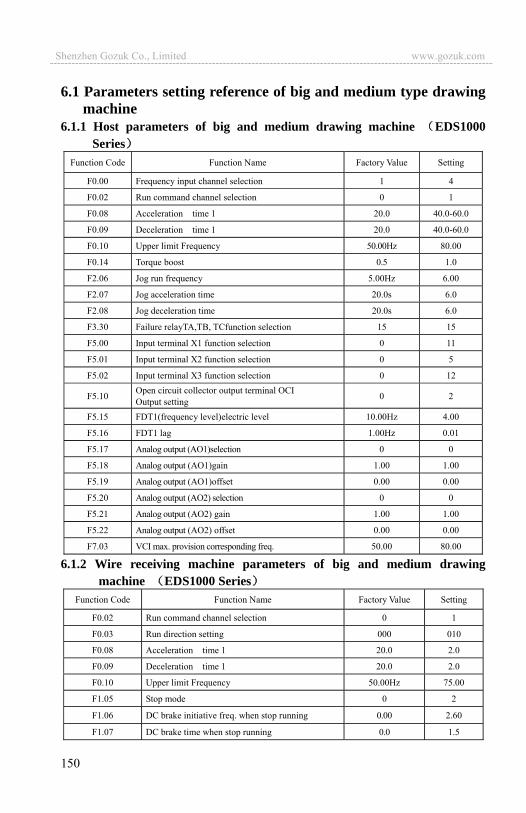
150
6.1 Parameters setting reference of big and medium type drawing machine
6.1.1 Host parameters of big and medium drawing machine EDS1000Series
Function Code Function Name Factory Value Setting
F0.00 Frequency input channel selection 1 4
F0.02 Run command channel selection 0 1
F0.08 Acceleration time 1 20.0 40.0-60.0
F0.09 Deceleration time 1 20.0 40.0-60.0
F0.10 Upper limit Frequency 50.00Hz 80.00
F0.14 Torque boost 0.5 1.0
F2.06 Jog run frequency 5.00Hz 6.00
F2.07 Jog acceleration time 20.0s 6.0
F2.08 Jog deceleration time 20.0s 6.0
F3.30 Failure relayTA,TB, TCfunction selection 15 15
F5.00 Input terminal X1 function selection 0 11
F5.01 Input terminal X2 function selection 0 5
F5.02 Input terminal X3 function selection 0 12
F5.10 Open circuit collector output terminal OCI Output setting 0 2
F5.15 FDT1(frequency level)electric level 10.00Hz 4.00
F5.16 FDT1 lag 1.00Hz 0.01
F5.17 Analog output (AO1)selection 0 0
F5.18 Analog output (AO1)gain 1.00 1.00
F5.19 Analog output (AO1)offset 0.00 0.00
F5.20 Analog output (AO2) selection 0 0
F5.21 Analog output (AO2) gain 1.00 1.00
F5.22 Analog output (AO2) offset 0.00 0.00
F7.03 VCI max. provision corresponding freq. 50.00 80.00
6.1.2 Wire receiving machine parameters of big and medium drawing machine EDS1000 Series
Function Code Function Name Factory Value Setting
F0.02 Run command channel selection 0 1
F0.03 Run direction setting 000 010
F0.08 Acceleration time 1 20.0 2.0
F0.09 Deceleration time 1 20.0 2.0
F0.10 Upper limit Frequency 50.00Hz 75.00
F1.05 Stop mode 0 2
F1.06 DC brake initiative freq. when stop running 0.00 2.60
F1.07 DC brake time when stop running 0.0 1.5
Shenzhen Gozuk Co., Limited www.gozuk.com---------------------------------------------------------------------------------------------------------------------------

151
F1.08 DC brake voltage when stop running 0 6
F2.00 Analog filter time constant 0.20s 0.03
F2.18 Acce. time 2(when start up smoothly ) 20.0 150.0
F2.19 Dece. time 2(when start up smoothly ) 20.0 150.0
F2.21 Interval time 1of retracting volume diameter calculation 500ms 300
F2.22 Empty diameter gain(retracting and releasing gain) 100.0 40.0
F2.23 PID adjustor gain 30.0 30.0
F2.24 Start-up volume diameter calculation gain selection 0 0
F2.25 Start-up volume diameter calculation gain(volume diameter calculation gain 4) 2.0 1.0
F2.26 Volume diameter calculation gain 3 0.4 0.4
F2.27 Volume diameter calculation gain 2 0.0 0.0
F2.28 Volume diameter calculation gain 1 0.0 0.0
F2.29 High limit of retracting volume gain 200.0 100.0
F2.30 Start-up retracting and releasing gain control 1 1
F2.31 Retracting and releasing speed gain +/- control 0 0
F2.32 Retracting and releasing recombination control 0 0
F2.33 Interval time 0of retracting volume diameter calculation 800 800
F2.34 Dead zone of retracting volume diameter calculation 0.10 0.10
F2.35 Range 1of retracting volume diameter calculation 0.70 0.70
F2.36 Range 2 of retracting volume diameter calculation 1.20 1.20
F2.37 Range 3 of retracting volume diameter calculation 1.70 1.70
F2.38 Range 4 of retracting volume diameter calculation 2.20 2.20
F2.39 Time of starting up smoothly 2000 2000
F2.40 Start up PID again control 1 1
F2.41 Start up PID smoothly selection 1 1
F2.42 Volume reset control 0 0
F2.43 Wire disconnecting delay PID control 1 1
F2.44 Time of wire disconnecting delay 5000 5000
F3.00 Closed-loop run 0 1
F3.08 proportion gain KP 0.250 0.800
F3.09 KI Integral gain KI 0.010 0.010
F3.12 Deviation margin 1.0(%) 1.0
F3.20 PID proportion gain 2 0.300 1.000
F3.21 PID Integral gain 2 0.000 0.000
F3.22 PID parameter self adjustment basis 1 1
F3.30 Failure relayTA,TB, TCfunction selection 15 15
F5.01 Input terminal X2 function selection 0 11
Shenzhen Gozuk Co., Limited www.gozuk.com---------------------------------------------------------------------------------------------------------------------------

152
F5.02 Input terminal X3 function selection 0 12
F5.10 Open circuit collector output terminal OCI Output setting 0 2
F5.15 FDT1(frequency level )electric level 2.60Hz 2.60Hz
F5.16 FDT1 lag 0.01Hz 0.01Hz
F7.03 VCI max provision corresponding freq. 50.00 75.00
7.1 parameters setting reference of fine-drawing machine and micro-pulling machine
7.1.1 Host parameters of fine-drawing machine and micro-pulling machine
EDS1000 SeriesFunction Code Function Name Factory Value Setting
F0.00 Frequency input channel selection 1 4
F0.02 Run command channel selection 0 1
F0.08 Acceleration time 1 20.0 40.0-60.0
F0.09 Deceleration time 1 20.0 40.0-60.0
F0.10 Upper limit Frequency 50.00Hz 80.00
F0.14 Torque boost 0.5 2.5
F2.06 Jog run frequency 5.00Hz 6.00
F2.07 Jog acceleration time 20.0s 6.0
F2.08 Jog deceleration time 20.0s 6.0
F3.30 Failure relayTA,TB, TCfunction selection 15 15
F5.00 Input terminal X1 function selection 0 11
F5.01 Input terminal X2 function selection 0 5
F5.02 Input terminal X3 function selection 0 12
F5.10 Open circuit collector output terminal OCI output setting 0 2
F5.15 FDT1(frequency level)electric level 10.00Hz 5.50
F5.16 FDT1 lag 1.00Hz 0.01
F5.17 Analog output (AO1)selection 0 0
F5.18 Analog output (AO1)gain 1.00 1.00
F5.19 Analog output (AO1)offset 0.00 0.00
F5.20 Analog output (AO2) selection 0 0
F5.21 Analog output (AO2) gain 1.00 1.00
F5.22 Analog output (AO2) offset 0.00 0.00
F7.03 VCI max. provision corresponding freq. 50.00 80.00
Shenzhen Gozuk Co., Limited www.gozuk.com---------------------------------------------------------------------------------------------------------------------------
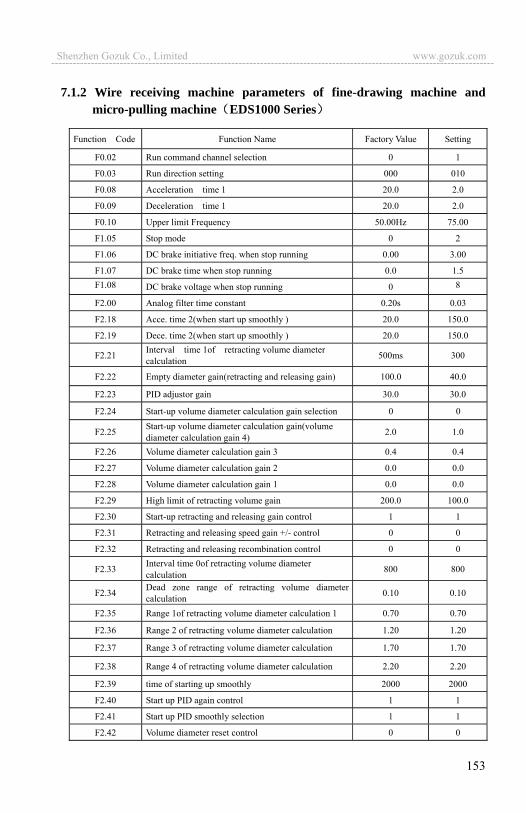
153
7.1.2 Wire receiving machine parameters of fine-drawing machine and micro-pulling machine EDS1000 Series
Function Code Function Name Factory Value Setting
F0.02 Run command channel selection 0 1
F0.03 Run direction setting 000 010
F0.08 Acceleration time 1 20.0 2.0
F0.09 Deceleration time 1 20.0 2.0
F0.10 Upper limit Frequency 50.00Hz 75.00
F1.05 Stop mode 0 2
F1.06 DC brake initiative freq. when stop running 0.00 3.00
F1.07 DC brake time when stop running 0.0 1.5 F1.08 DC brake voltage when stop running 0 8
F2.00 Analog filter time constant 0.20s 0.03
F2.18 Acce. time 2(when start up smoothly ) 20.0 150.0
F2.19 Dece. time 2(when start up smoothly ) 20.0 150.0
F2.21 Interval time 1of retracting volume diameter calculation 500ms 300
F2.22 Empty diameter gain(retracting and releasing gain) 100.0 40.0
F2.23 PID adjustor gain 30.0 30.0
F2.24 Start-up volume diameter calculation gain selection 0 0
F2.25 Start-up volume diameter calculation gain(volume diameter calculation gain 4) 2.0 1.0
F2.26 Volume diameter calculation gain 3 0.4 0.4
F2.27 Volume diameter calculation gain 2 0.0 0.0
F2.28 Volume diameter calculation gain 1 0.0 0.0
F2.29 High limit of retracting volume gain 200.0 100.0
F2.30 Start-up retracting and releasing gain control 1 1
F2.31 Retracting and releasing speed gain +/- control 0 0
F2.32 Retracting and releasing recombination control 0 0
F2.33 Interval time 0of retracting volume diameter calculation 800 800
F2.34 Dead zone range of retracting volume diameter calculation 0.10 0.10
F2.35 Range 1of retracting volume diameter calculation 1 0.70 0.70
F2.36 Range 2 of retracting volume diameter calculation 1.20 1.20
F2.37 Range 3 of retracting volume diameter calculation 1.70 1.70
F2.38 Range 4 of retracting volume diameter calculation 2.20 2.20
F2.39 time of starting up smoothly 2000 2000
F2.40 Start up PID again control 1 1
F2.41 Start up PID smoothly selection 1 1
F2.42 Volume diameter reset control 0 0
Shenzhen Gozuk Co., Limited www.gozuk.com---------------------------------------------------------------------------------------------------------------------------
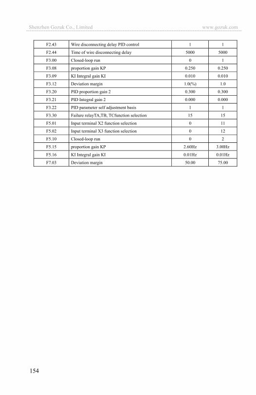
154
F2.43 Wire disconnecting delay PID control 1 1
F2.44 Time of wire disconnecting delay 5000 5000
F3.00 Closed-loop run 0 1
F3.08 proportion gain KP 0.250 0.250
F3.09 KI Integral gain KI 0.010 0.010
F3.12 Deviation margin 1.0(%) 1.0
F3.20 PID proportion gain 2 0.300 0.300
F3.21 PID Integral gain 2 0.000 0.000
F3.22 PID parameter self adjustment basis 1 1
F3.30 Failure relayTA,TB, TCfunction selection 15 15
F5.01 Input terminal X2 function selection 0 11
F5.02 Input terminal X3 function selection 0 12
F5.10 Closed-loop run 0 2
F5.15 proportion gain KP 2.60Hz 3.00Hz
F5.16 KI Integral gain KI 0.01Hz 0.01Hz
F7.03 Deviation margin 50.00 75.00
Shenzhen Gozuk Co., Limited www.gozuk.com---------------------------------------------------------------------------------------------------------------------------
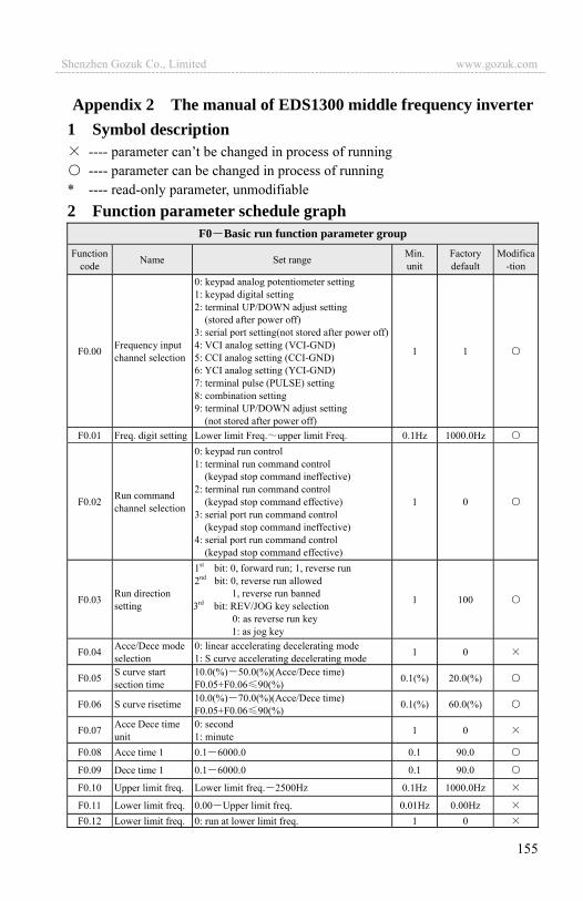
155
Appendix 2 The manual of EDS1300 middle frequency inverter 1 Symbol description
---- parameter can’t be changed in process of running ---- parameter can be changed in process of running
* ---- read-only parameter, unmodifiable 2 Function parameter schedule graph
F0 Basic run function parameter groupFunction
code Name Set range Min. unit
Factory default
Modifica-tion
F0.00 Frequency input channel selection
0: keypad analog potentiometer setting 1: keypad digital setting 2: terminal UP/DOWN adjust setting
(stored after power off) 3: serial port setting(not stored after power off) 4: VCI analog setting (VCI-GND) 5: CCI analog setting (CCI-GND) 6: YCI analog setting (YCI-GND) 7: terminal pulse (PULSE) setting 8: combination setting 9: terminal UP/DOWN adjust setting (not stored after power off)
1 1
F0.01 Freq. digit setting Lower limit Freq. upper limit Freq. 0.1Hz 1000.0Hz
F0.02 Run command channel selection
0: keypad run control 1: terminal run command control
(keypad stop command ineffective) 2: terminal run command control
(keypad stop command effective) 3: serial port run command control
(keypad stop command ineffective) 4: serial port run command control
(keypad stop command effective)
1 0
F0.03 Run direction setting
1st bit: 0, forward run; 1, reverse run 2nd bit: 0, reverse run allowed 1, reverse run banned
3rd bit: REV/JOG key selection 0: as reverse run key 1: as jog key
1 100
F0.04 Acce/Dece mode selection
0: linear accelerating decelerating mode 1: S curve accelerating decelerating mode 1 0
F0.05 S curve start section time
10.0(%) 50.0(%)(Acce/Dece time) F0.05+F0.06 90(%) 0.1(%) 20.0(%)
F0.06 S curve risetime 10.0(%) 70.0(%)(Acce/Dece time) F0.05+F0.06 90(%) 0.1(%) 60.0(%)
F0.07 Acce Dece time unit
0: second 1: minute 1 0
F0.08 Acce time 1 0.1 6000.0 0.1 90.0
F0.09 Dece time 1 0.1 6000.0 0.1 90.0
F0.10 Upper limit freq. Lower limit freq. 2500Hz 0.1Hz 1000.0Hz
F0.11 Lower limit freq. 0.00 Upper limit freq. 0.01Hz 0.00Hz F0.12 Lower limit freq. 0: run at lower limit freq. 1 0
Shenzhen Gozuk Co., Limited www.gozuk.com---------------------------------------------------------------------------------------------------------------------------
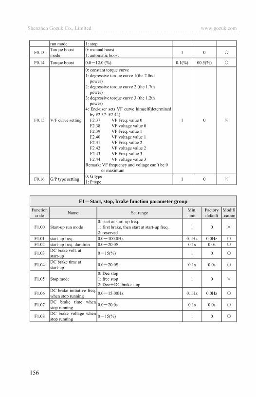
156
run mode 1: stop
F0.13 Torque boost mode
0: manual boost 1: automatic boost 1 0
F0.14 Torque boost 0.0 12.0 (%) 0.1(%) 00.5(%)
F0.15 V/F curve setting
0: constant torque curve 1: degressive torque curve 1(the 2.0nd
power) 2: degressive torque curve 2 (the 1.7th
power) 3: degressive torque curve 3 (the 1.2th
power) 4: End-user sets VF curve himself(determined
by F2.37~F2.44) F2.37 VF Freq. value 0 F2.38 VF voltage value 0 F2.39 VF Freq. value 1 F2.40 VF voltage value 1 F2.41 VF Freq. value 2 F2.42 VF voltage value 2 F2.43 VF Freq. value 3 F2.44 VF voltage value 3 Remark: VF frequency and voltage can’t be 0
or maximum
1 0
F0.16 G/P type setting 0: G type 1: P type 1 0
F1 Start, stop, brake function parameter groupFunction
code Name Set range Min. unit
Factory default
Modifi-cation
F1.00 Start-up run mode 0: start at start-up freq. 1: first brake, then start at start-up freq. 2: reserved
1 0
F1.01 start-up freq. 0.0 100.0Hz 0.1Hz 0.0HzF1.02 start-up freq. duration 0.0 20.0S 0.1s 0.0s
F1.03 DC brake volt. at start-up 0 15(%) 1 0
F1.04 DC brake time at start-up 0.0 20.0S 0.1s 0.0s
F1.05 Stop mode 0: Dec stop 1: free stop 2: Dec DC brake stop
1 0
F1.06 DC brake initiative freq. when stop running 0.0 15.00Hz 0.1Hz 0.0Hz
F1.07 DC brake time when stop running 0.0 20.0s 0.1s 0.0s
F1.08 DC brake voltage when stop running 0 15(%) 1 0
Shenzhen Gozuk Co., Limited www.gozuk.com---------------------------------------------------------------------------------------------------------------------------

157
F2 Auxiliary run function parameter group
Functioncode Name Set range Min.
unit Factory default
Modificat-ion
F2.00 Analog filter time constant 0.00 30.00s 0.01s 0.20s
F2.01 Forward reverse run dead-section time 0.0 3600.0s 0.1s 0.1s
F2.02 Automatic energy save run
0: no action 1: action 1 0
F2.03 AVR function 0: no action 1: action all the time 2: no action only during Dec
1 0
F2.04 Slip frequency compensation
0 150(%)0-no slip frequency compensation 1 0
F2.05 Carrier wave freq. 2 15.0K 0.1K depend on machine type
F2.06 Jog run frequency 1.0 1000.0Hz 0.1Hz 50.0Hz
F2.07 Jog Acc time 0.1 60.0s 0.1s 20.0s
F2.08 Jog Dec time 0.1 60.0s 0.1s 20.0s
F2.09 Frequency input channel combination
0: VCI CCI 1: VCI CCI 2: YCI CCI 3: RS485+YCI 4: VCI YCI 5: reserved 6: exterior pulse provision
CCI 7: exterior pulse provision
CCI 8: reserved 9: reserved 10: reserved 11: reserved 12: reserved 13: VCI CCI any nonzero
value effective, VCI preferred
14: reserved 15: RS485+CCI 16: RS485-CCI 17: RS485+VCI 18: RS485-VCI 19: RS485+keypad
potentiometer 20: RS485- keypad
potentiometer 21: VCI+ keypad
potentiometer 22: VCI- keypad potentiometer 23: CCI+ keypad
potentiometer 24: CCI- keypad potentiometer 25: reserved 26: reserved 27: reserved 28: reserved
1 0
Shenzhen Gozuk Co., Limited www.gozuk.com---------------------------------------------------------------------------------------------------------------------------
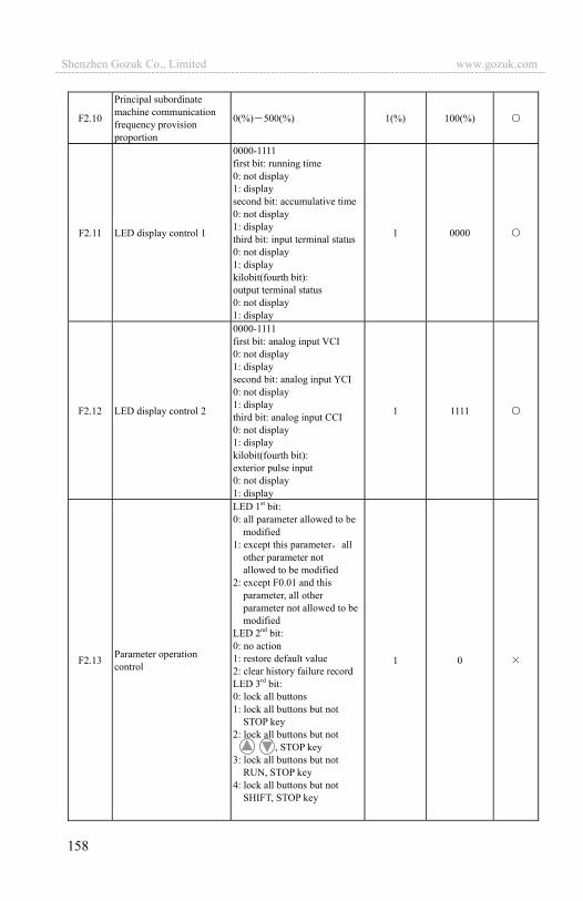
158
F2.10
Principal subordinate machine communication frequency provision proportion
0(%) 500(%) 1(%) 100(%)
F2.11 LED display control 1
0000-1111 first bit: running time 0: not display 1: display second bit: accumulative time 0: not display 1: display third bit: input terminal status 0: not display 1: display kilobit(fourth bit): output terminal status 0: not display 1: display
1 0000
F2.12 LED display control 2
0000-1111 first bit: analog input VCI 0: not display 1: display second bit: analog input YCI 0: not display 1: display third bit: analog input CCI 0: not display 1: display kilobit(fourth bit): exterior pulse input 0: not display 1: display
1 1111
F2.13 Parameter operation control
LED 1st bit: 0: all parameter allowed to be
modified 1: except this parameter all
other parameter not allowed to be modified
2: except F0.01 and this parameter, all other parameter not allowed to be modified
LED 2nd bit: 0: no action 1: restore default value 2: clear history failure record LED 3rd bit: 0: lock all buttons 1: lock all buttons but not
STOP key 2: lock all buttons but not
, STOP key 3: lock all buttons but not RUN, STOP key 4: lock all buttons but not SHIFT, STOP key
1 0
Shenzhen Gozuk Co., Limited www.gozuk.com---------------------------------------------------------------------------------------------------------------------------

159
F2.14 Communication configuration
LED first bit: baud rate selection 0: 1200BPS 1: 2400BPS 2: 4800BPS 3: 9600BPS 4: 19200BPS 5: 38400BPS LED second bit: data format 0: 1 8 1format, no checkout 1: 1 8 1 format,
even checkout 2: 1 8 1 format,
odd checkout
1 03
F2.15 Local address
0 127 127 is broadcast address. The inverter only receive but not send when it is set to be 127, 0 is address for main device.
1 1
F2.16 Communication overtime 0.0 1000.0s 0.1s 0.0s
F2.17 Local response delay 0 1000ms 1ms 5ms
F2.18 Acce time 2 0.1 6000.0 0.1 20.0 F2.19 Dece time 2 0.1 6000.0 0.1 20.0 F2.20 Acce time 3 0.1 6000.0 0.1 20.0 F2.21 Dece time 3 0.1 6000.0 0.1 20.0 F2.22 Acce time 4 0.1 6000.0 0.1 20.0 F2.23 Dece time 4 0.1 6000.0 0.1 20.0 F2.24 Acce time 5 0.1 6000.0 0.1 20.0 F2.25 Dece time 5 0.1 6000.0 0.1 20.0 F2.26 Acce time 6 0.1 6000.0 0.1 20.0 F2.27 Dece time 6 0.1 6000.0 0.1 20.0 F2.28 Acce time 7 0.1 6000.0 0.1 20.0 F2.29 Dece time 7 0.1 6000.0 0.1 20.0
F2.30 Multisection freq. 1 Lower limit freq. upper limit freq. 0.1Hz 100.0Hz
F2.31 Multisection freq. 2 Lower limit freq. upper limit freq. 0.1Hz 200.0Hz
F2.32 Multisection freq. 3 Lower limit freq. upper limit freq. 0.1Hz 300.0Hz
F2.33 Multisection freq. 4 Lower limit freq. upper limit freq. 0.1Hz 400.0Hz
F2.34 Multisection freq. 5 Lower limit freq. upper limit freq. 0.1Hz 500.0Hz
F2.35 Multisection freq. 6 Lower limit freq. upper limit freq. 0.1Hz 600.0Hz
F2.36 Multisection freq. 7 Lower limit freq. upper limit freq. 0.1Hz 700.0Hz
F2.37 VF frequency value 0 0.00-F2.39 0.01Hz 10.00Hz F2.38 VF voltage value 0 0.00-F2.40 0.01% 20.00% F2.39 VF frequency value 1 F2.37-F2.41 0.01Hz 20.00Hz F2.40 VF voltage value 1 F2.38-F2.42 0.01% 40.00% F2.41 VF frequency value 2 F2.39-F2.43 0.01Hz 25.00Hz F2.42 VF voltage value 2 F2.40-F2.44 0.01% 50.00% F2.43 VF frequency value 3 F2.41-high limit frquency 0.01Hz 40.00Hz F2.44 VF voltage value 3 F2.42-100.0% (rated voltage) 0.01% 80.00%
Shenzhen Gozuk Co., Limited www.gozuk.com---------------------------------------------------------------------------------------------------------------------------

160
F2.45 Jumping freq. 1 0.00 400.00Hz 0.1Hz 0.00Hz F2.46 Jumping freq. 1 range 0.00 30.00Hz 0.1Hz 0.00Hz F2.47 Jumping freq. 2 0.00 400.00Hz 0.1Hz 0.00Hz F2.48 Jumping freq. 2 range 0.00 30.00Hz 0.1Hz 0.00Hz F2.49 Jumping freq. 3 0.00 400.00Hz 0.1Hz 0.00Hz F2.50 Jumping freq. 3 range 0.00 30.00Hz 0.1Hz 0.00Hz F2.51 Setting run time 0 65535 hours 1 0 F2.52 Accumulative run time 0 65535 hours 1 0 *
F2.53 RS485/232 communication frame format selection
0: a ASCII frame of 14 byte or 18 byte
1: a hex frame of 8 byte or 10 byte, original response not changed
2: a hex frame of 8 byte or 10 byte, 12 command has no response
3: a hex frame of 8 byte or 10 byte, 14 command has no response
4: a hex frame of 8 byte or 10 byte, both 12 and 14 command have no response
1 0
F3 Closed-loop run function parameter group Function
code Name Set range Min. unit
Factory default
Modifi-cation
F3.00 Closed-loop run control selection
0: closed-loop control ineffective 1: PID closed-loop control effective 2: reserved
1 0
F3.01 Provision channel selection
0: digital provision 1: VCI analog 0 10V voltage provision 2: CCI analog provision 3: keypad potentiometer provision
1 1
F3.02 Feedback channel selection
0: VCI analog input voltage 0 10V 1: CCI analog input 2: VCI+CCI 3: VCI-CCI 4: Min { VCI, CCI } 5: Max { VCI, CCI } 6: pulse feedback
1 1
F3.03 Specified value digital setting 0.00~10.00V(setF3.00=1,F3.21=9.999) 0.01 0.00
F3.04 Minimum specified value
0.0 maximum specified value; percentage relative to 10.00V 0.1(%) (0.0)%
F3.05
feedback value responding to minimum specified value
0.0 100.0(%) 0.1(%) (0.0)%
F3.06 maximum specified value
Minimum specified value 100.0(%) 0.1(%) 100.0(%)
F3.07
feedback value responding to maximum specified value
0.0 100.0(%) 0.1(%) 100.0(%)
Shenzhen Gozuk Co., Limited www.gozuk.com---------------------------------------------------------------------------------------------------------------------------

161
F3.08 proportion gain Kp 0.000 9.999 0.001 0.050F3.09 Integral gain Ki 0.000 9.999 0.001 0.050F3.10 Differential gain Kd 0.000 9.999 0.001 0.000F3.11 Sampling cycle T 0.01 1.00s 0.01s 0.10sF3.12 Deviation margin 0.0 20.0(%)percentage relative to 10.00V 0.1(%) 2.0(%)
F3.13 Integral separation PID adjusting threshold
0.0 100.0% 0.1% 100.0%
F3.14 Closed-lop preset frequency 0 upper limit frequency 0.01Hz 000.0hz
F3.15 Closed-loop preset frequency holding time
0.0-6000s 0.1s 000.0s
F3.16 reserved F3.17 reserved F3.18 reserved F3.19 reserved
F3.20 reserved
F3.21 reserved F3.22 reserved F3.23 reserved F3.24 reserved F3.25 reserved F3.26 reserved
F3.27 Closed-loop adjusting characteristic
0: Forward function 1: Reverse function 0
F3.28 LED initial supervision parameter selection
0: set frequency 1: output frequency 2: output current 3: output voltage 4: DC bus bar voltage 5: motor speed 6: heat sink temperature 7: run time 8: accumulative run time 9: input terminal status 10: output terminal status 11: analog input VCI/PID provision 12: analog input CCI/PID feedback 13: analog input YCI 14: exterior pulse inputs
1
F3.29 YCI run-in delay time 0.0 999.9s 0.1 10.0
F3.30 Failure relay TA TBTC function selection
0: inverter running(RUN) 1: frequency arriving signal(FAR) 2: frequency level detect signal (FDT1) 3: reserved 4: overload warning alarm signal (OL) 5: output frequency reach high limit(FHL) 6: output frequency reach low limit(FLL) 7: inverter under voltage blockage stop (LU) 8: external failure stop-running(EXT) 9: inverter zero speed running 10: PLC running 11: simple PLC section running finished 12: PLC finish a cycle running 13: reserved
15
Shenzhen Gozuk Co., Limited www.gozuk.com---------------------------------------------------------------------------------------------------------------------------
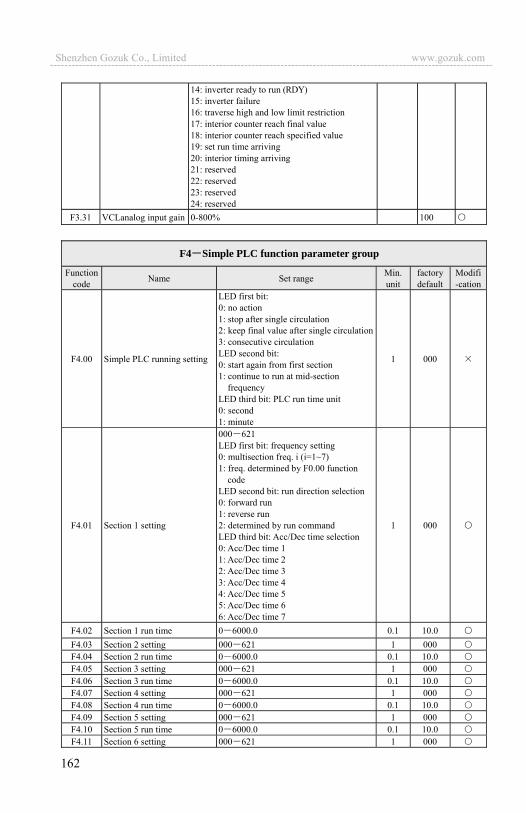
162
14: inverter ready to run (RDY) 15: inverter failure 16: traverse high and low limit restriction 17: interior counter reach final value 18: interior counter reach specified value 19: set run time arriving 20: interior timing arriving 21: reserved 22: reserved 23: reserved 24: reserved
F3.31 VCLanalog input gain 0-800% 100
F4 Simple PLC function parameter group
Functioncode Name Set range Min.
unit factory default
Modifi-cation
F4.00 Simple PLC running setting
LED first bit: 0: no action 1: stop after single circulation 2: keep final value after single circulation 3: consecutive circulation LED second bit: 0: start again from first section 1: continue to run at mid-section
frequency LED third bit: PLC run time unit 0: second 1: minute
1 000
F4.01 Section 1 setting
000 621 LED first bit: frequency setting 0: multisection freq. i (i=1~7) 1: freq. determined by F0.00 function
codeLED second bit: run direction selection 0: forward run 1: reverse run 2: determined by run command LED third bit: Acc/Dec time selection 0: Acc/Dec time 1 1: Acc/Dec time 2 2: Acc/Dec time 3 3: Acc/Dec time 4 4: Acc/Dec time 5 5: Acc/Dec time 6 6: Acc/Dec time 7
1 000
F4.02 Section 1 run time 0 6000.0 0.1 10.0 F4.03 Section 2 setting 000 621 1 000 F4.04 Section 2 run time 0 6000.0 0.1 10.0 F4.05 Section 3 setting 000 621 1 000 F4.06 Section 3 run time 0 6000.0 0.1 10.0 F4.07 Section 4 setting 000 621 1 000 F4.08 Section 4 run time 0 6000.0 0.1 10.0 F4.09 Section 5 setting 000 621 1 000 F4.10 Section 5 run time 0 6000.0 0.1 10.0 F4.11 Section 6 setting 000 621 1 000
Shenzhen Gozuk Co., Limited www.gozuk.com---------------------------------------------------------------------------------------------------------------------------
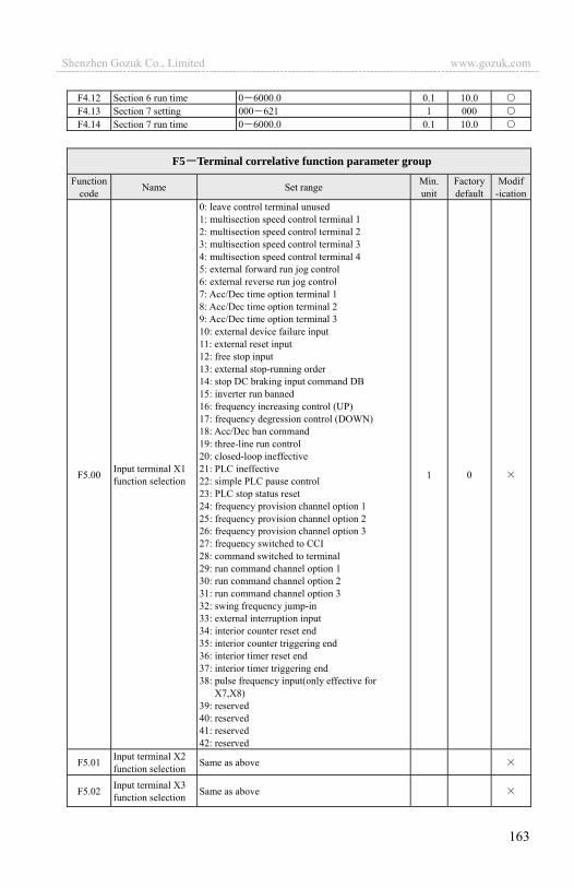
163
F4.12 Section 6 run time 0 6000.0 0.1 10.0 F4.13 Section 7 setting 000 621 1 000 F4.14 Section 7 run time 0 6000.0 0.1 10.0
F5 Terminal correlative function parameter groupFunction
code Name Set range Min.unit
Factory default
Modif-ication
F5.00 Input terminal X1 function selection
0: leave control terminal unused 1: multisection speed control terminal 1 2: multisection speed control terminal 2 3: multisection speed control terminal 3 4: multisection speed control terminal 4 5: external forward run jog control 6: external reverse run jog control 7: Acc/Dec time option terminal 1 8: Acc/Dec time option terminal 2 9: Acc/Dec time option terminal 3 10: external device failure input 11: external reset input 12: free stop input 13: external stop-running order 14: stop DC braking input command DB 15: inverter run banned 16: frequency increasing control (UP) 17: frequency degression control (DOWN) 18: Acc/Dec ban command 19: three-line run control 20: closed-loop ineffective 21: PLC ineffective 22: simple PLC pause control 23: PLC stop status reset 24: frequency provision channel option 1 25: frequency provision channel option 2 26: frequency provision channel option 3 27: frequency switched to CCI 28: command switched to terminal 29: run command channel option 1 30: run command channel option 2 31: run command channel option 3 32: swing frequency jump-in 33: external interruption input 34: interior counter reset end 35: interior counter triggering end 36: interior timer reset end 37: interior timer triggering end 38: pulse frequency input(only effective for
X7,X8) 39: reserved 40: reserved 41: reserved 42: reserved
1 0
F5.01 Input terminal X2 function selection Same as above
F5.02 Input terminal X3 function selection Same as above
Shenzhen Gozuk Co., Limited www.gozuk.com---------------------------------------------------------------------------------------------------------------------------
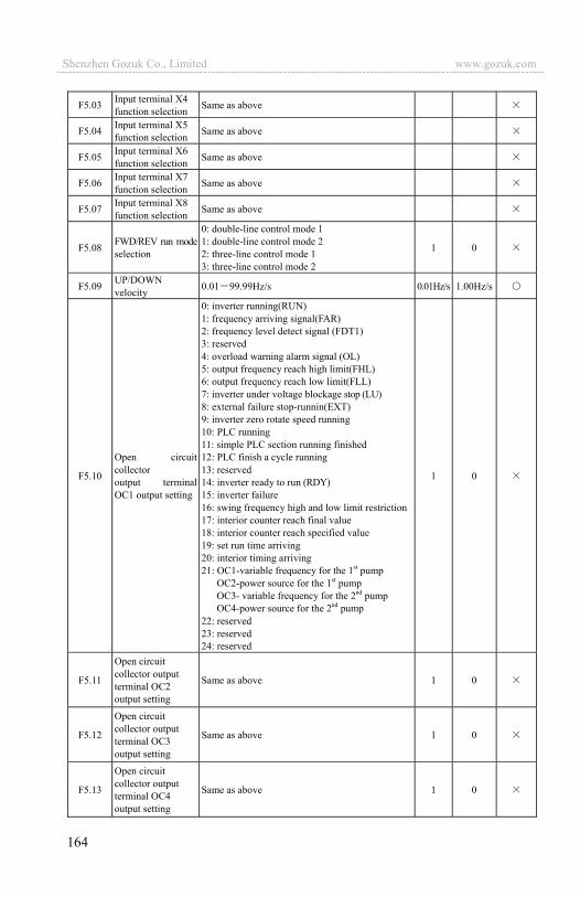
164
F5.03 Input terminal X4 function selection Same as above
F5.04 Input terminal X5 function selection Same as above
F5.05 Input terminal X6 function selection Same as above
F5.06 Input terminal X7 function selection Same as above
F5.07 Input terminal X8 function selection Same as above
F5.08 FWD/REV run mode selection
0: double-line control mode 1 1: double-line control mode 2 2: three-line control mode 1 3: three-line control mode 2
1 0
F5.09 UP/DOWN velocity 0.01 99.99Hz/s 0.01Hz/s 1.00Hz/s
F5.10
Open circuit collector output terminalOC1 output setting
0: inverter running(RUN) 1: frequency arriving signal(FAR) 2: frequency level detect signal (FDT1) 3: reserved 4: overload warning alarm signal (OL) 5: output frequency reach high limit(FHL) 6: output frequency reach low limit(FLL) 7: inverter under voltage blockage stop (LU) 8: external failure stop-runnin(EXT) 9: inverter zero rotate speed running 10: PLC running 11: simple PLC section running finished 12: PLC finish a cycle running 13: reserved 14: inverter ready to run (RDY) 15: inverter failure 16: swing frequency high and low limit restriction17: interior counter reach final value 18: interior counter reach specified value 19: set run time arriving 20: interior timing arriving 21: OC1-variable frequency for the 1st pump
OC2-power source for the 1st pump OC3- variable frequency for the 2nd pump OC4-power source for the 2nd pump
22: reserved 23: reserved 24: reserved
1 0
F5.11
Open circuit collector output terminal OC2 output setting
Same as above 1 0
F5.12
Open circuit collector output terminal OC3 output setting
Same as above 1 0
F5.13
Open circuit collector output terminal OC4 output setting
Same as above 1 0
Shenzhen Gozuk Co., Limited www.gozuk.com---------------------------------------------------------------------------------------------------------------------------
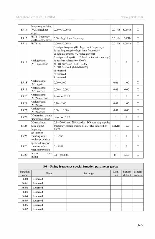
165
F5.14 Frequency arriving (FAR) checkout scope
0.00 50.00Hz 0.01Hz 5.00Hz
F5.15 FDT1 (frequency level) electric level 0.00 high limit frequency 0.01Hz 10.00Hz
F5.16 FDT1 lag 0.00 50.00Hz 0.01Hz 1.00Hz
F5.17 Analog output (AO1) selection
0: output frequency(0 high limit frequency) 1: set frequency(0 high limit frequency) 2: output current(0 2×rated current) 3: output voltage(0 1.2×load motor rated voltage)4: bus-bar voltage(0 800V)5: PID provision (0.00-10.00V) 6: PID feedback (0.00-10.00V) 7: reserved 8: reserved 9: reserved
1 0
F5.18 Analog output (AO1) gain 0.00 2.00 0.01 1.00
F5.19 Analog output (AO1) offset 0.00 10.00V 0.01 0.00
F5.20 Analog output (AO2) selection Same as F5.17 1 0
F5.21 Analog output (AO2) gain 0.10 2.00 0.01 1.00
F5.22 Analog output (AO2) offset 0.00 10.00V 0.01 0.00
F5.23 DO terminal output function selection Same as F5.17 1 0
F5.24 DO maximum pulse output frequency
0.1 20.0(max. 20KHz)Max. DO port output pulse frequency corresponds to Max. value selected by F5.23
0.1KHz 10.0
F5.25 Set interior counting value reaches provision
0 9999 1 0
F5.26 Specified interior counting value reaches provision
0 9999 1 0
F5.27 Interior timer setting 0.1 6000.0s 0.1 60.0
F6 Swing frequency special function parameter groupFunction
code Name Set range Min.unit
Factory default
Modifi-cation
F6.00 Reserved
F6.01 Reserved
F6.02 Reserved
F6.03 Reserved
F6.04 Reserved
F6.05 Reserved
F6.06 Reserved
F6.07 Reserved
Shenzhen Gozuk Co., Limited www.gozuk.com---------------------------------------------------------------------------------------------------------------------------

166
F7 Frequency provision function parameter groupFunction
code Name Set range Min.unit
Factory default
Modifi-cation
F7.00 VCI min. provision 0.00 F7.02 0.01V 0.00V F7.01 VCI min. provision corresponding freq. 0.00 high limit frequency 0.01Hz 000.0 HzF7.02 VCI max. provision 0.00 10.00V 0.01V 9.99V F7.03 VCI max. provision corresponding freq. 0.00 high limit frequency 0.01 Hz 1000 HzF7.04 CCI min. provision 0.00 F7.06 0.01V 0.00V F7.05 CCI min. provision corresponding freq. 0.00 high limit frequency 0.01 Hz 000.0 HzF7.06 CCI max. provision 0.00 10.00V 0.01V 9.99V F7.07 CCI max. provision corresponding freq. 0.00 high limit frequency 0.01 Hz 1000 HzF7.08 YCI min. provision 0.00 F7.10 0.01V 00.03V
F7.09 YCI min. provision corresponding freq. 0.00 high limit frequency(reverse run) 0.01 Hz 500.0 Hz
F7.10 YCI max. provision 0.00 10.00V 0.01V 9.99V
F7.11 YCI max. provision corresponding freq. 0.00 high limit frequency (forward run) 0.01Hz 1000Hz
F7.12 YCI dead area setting 0.00V 2.00V 0.01V 0.10V
F7.13 PULSE max. input pulse 0.01 20.0K 0.01K 10.0K
F7.14 PULSE min. provision 0.0 F7.16(PULSE max. provision) 0.01K 0.0K
F7.15 PULSE min. provision corresponding freq. 0.00 high limit frequency 0.01Hz 000.0Hz
F7.16 PULSE max. provision F7.14 (PULSE min. provision) F7.13 (max. input pulse)
0.1K 10.0K
F7.17 PULSE max. provision corresponding freq. 0.00 high limit frequency 0.01Hz 1000Hz
F8 Motor and vector control parameter groupFunction
code Name Set range Unit Factory default
Modifi-cation
F8.00 Control mode setting 0: V/F control 1: vector control remark: for EDS1300 it can’t be 1
1 0
F8.01 Motor rated voltage 1 480V 1V Depend on device type
F8.02 Motor rated current 0.1 999.9A 0.1A Depend on device type
F8.03 Motor rated frequency 10.0 1000.0Hz 0.01 Hz Depend on device type
F8.04 Motor rated speed 1 9999r/min 1r/min Depend on device type
F8.05 Motor pole 2 14 2 Depend on device type
F8.06 Motor rated power 0.1 999.9KW 0.1 Depend on device type
F8.07 Reserved
F8.08 Reserved
Shenzhen Gozuk Co., Limited www.gozuk.com---------------------------------------------------------------------------------------------------------------------------

167
F8.09 Reserved F8.10 Reserved F8.11 Reserved F8.12 Reserved F8.13 Reserved F8.14 Reserved F8.15 Reserved F8.16 Reserved F8.17 Reserved
F9 Protection correlative function parameter group
Functioncode Name Set range Min.
unit Factory default
Modific-ation
F9.00 Instantaneous power off restarting latency time
0.0 10.0S 0 indicates ineffective power off restarting 0.1S 0.0S
F9.01 Failure self-renew times
0 10 0 shows no automatic reset function 1 0
F9.02 Failure self-renew interval 0.5 20.0S 0.1S 5.0S
F9.03 Motor overload protection mode selection
0: no action 1: inverter close off output 1 1
F9.04 Motor overload protection coefficient 20.0-120.0(%) 0.1(%) 100.0(%)
F9.05 Overload warning alarm checkout level 20 200(%) 1(%) 130(%)
F9.06 Overload warning alarmDelay time 0.0 20.0s 0.1s 5.0s
F9.07 Overvoltage stall selection
0: ban 1: allow 1 1
F9.08 Overvoltage stall point 120-150(%) 1(%) 120(%)
F9.09 Automatic current limit level 110 200(%) 1(%) 140(%)
F9.10 Frequency declining rate during current limiting
0.00 99.99Hz/s 0.01Hz/s 10.00Hz/s
F9.11 Automatic current limiting action selection
0: constant speed ineffective 1: constant speed effective remark: Acc/Dec always effective
1 0
Fd Failure record function parameter groupFunction
code Name Setting range Min.unit
Factory default
Modifi-cation
Fd.00 Previous one time failure record Previous one time failure record 1 0 * Fd.01 Previous two time failure record Previous two time failure record 1 0 * Fd.02 Previous three time failure record Previous three time failure record 1 0 * Fd.03 Previous four time failure record Previous four time failure record 1 0 * Fd.04 Previous five time failure record Previous five time failure record 1 0 * Fd.05 Previous six time failure record Previous six time failure record 1 0 *
Shenzhen Gozuk Co., Limited www.gozuk.com---------------------------------------------------------------------------------------------------------------------------

168
Fd.06 Set freq. of previous failure Set freq. of previous failure 0.01Hz 0 *
Fd.07 output freq. of previous failure output freq. of previous failure 0.01Hz 0 *
Fd.08 output current of previous failure output current of previous failure 0.1A 0 *
Fd.09 output voltage of previous failure output voltage of previous failure 1V 0 *
Fd.10 DC bus-bar voltage of previous failure DC bus-bar voltage of previous failure 1V 0 *
Fd.11 Load motor speed of previous failure Load motor speed of previous failure 1(r/m) 0 *
Fd.12 Module temperature of previous failure Module temperature of previous failure 1 0 *
Fd.13 Input terminal status of previous failure Input terminal status of previous failure 11111111 *
Fd.14 Accumulative run time of previous failure
Accumulative run time of previous failure 0 *
FF Password and manufacturer function parameter group
Functioncode Name Setting range Min.
unitfactory default
Modific-ation
FF.00 User password 0000 9999 1 0000
FF.01 Manufacturer password 0000 9999 1 0000 FF.02- FF.0X Manufacturer’s special parameter
C Supervision function parameter groupFunction
code Name Description Min. unit
Factory default
Modific -ation
C-00 Set frequency Current set frequency 0.01HZ
C-01 Output freq. Current output freq. 0.01HZ *
C-02 Output current Virtual value of current output current 0.1A *
C-03 Output voltage Virtual value of current output voltage 1V *
C-04 DC bus-bar voltage Current DC bus-bar voltage 1V *
C-05 Load motor speed Product of output frequency and load motor speed emendation factor 1(r/m) *
C-06 Module temperature IGBT heat sink temperature 1 *
C-07 Run time Inverter electrification run time 1h *
C-08 Accumulative run time Inverter accumulative run time 1h *
C-09 Input terminal status Switch value input terminal status *
C-10 Output terminal status Switch value output terminal status *
C-11 Analog input VCI Analog input value of VCI V *
C-12 Analog input YCI Analog input value of YCI V *
C-13 Analog input CCI Analog input value of CCI V *
C-14 Exterior pulse input Exterior pulse input 0.1KHz *
Shenzhen Gozuk Co., Limited www.gozuk.com---------------------------------------------------------------------------------------------------------------------------
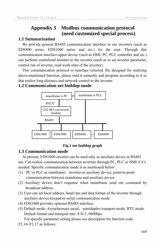
169
Appendix 3 Modbus communication protocol (need customized special process)
1.1 SummarizationWe provide general RS485 communication interface in our inverters (such as
EDS800 series, EDS1000 series and etc.) for the user. Through this communication interface upper device (such as HMI, PC, PLC controller and etc.) can perform centralized monitor to the inverter (such as to set inverter parameter, control run of inverter, read work state of the inverter).
This communication protocol is interface criterion file designed for realizing above-mentioned function, please read it earnestly and program according to it so that realize long-distance and network control to the inverter. 1.2 Communication net buildup mode
Fig.1 net buildup graph 1.3 Communication mode
At present, EDS1000 inverter can be used only as auxiliary device in RS485 net. Can realize communication between inverters through PC, PLC or HMI if it’s needed. Specific communication mode is as mentioned below: (1) PC or PLC as mainframe inverter as auxiliary device, point-to-point
communication between mainframe and auxiliary device. (2) Auxiliary device don’t response when mainframe send out command by
broadcast address. (3) User can set local address, baud rate and data format of the inverter through
auxiliary device keypad or serial communication mode. (4) EDS1000 provides optional RS485 interface. (5) Default mode: Asynchronous serial semiduplex transport mode. RTU mode.
Default format and transport rate: 8-N-1, 9600bps. For specific parameter setting please see description for function code
F2.14~F2.17 as follows:
EDS1000 EDS1000 EDS800 EDS800
mainframe is PC mainframe is PLC
232-485 conversionmodule
or
RS232
RS485
Shenzhen Gozuk Co., Limited www.gozuk.com---------------------------------------------------------------------------------------------------------------------------
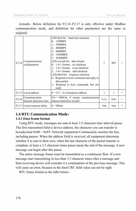
170
(remark Below definition for F2.14~F2.17 is only effective under Modbus communication mode, and definition for other parameters are the same as original)
F2.14 Communication configuration
LED first bit baud rate selection 0 1200BPS 1 2400BPS 2 4800BPS 3 9600BPS 4 19200BPS 5 38400BPS LED second bit data format 0 1-8-1 format no checkout 1 1-8-1 format even checkout 2 1-8-1 format odd checkout LED third bit response selection 0 Respond to host command and reply to
data packet 1 Respond to host command, but not
reply
1 003 ×
F2.15 Local address 0 127 0 is broadcast address 1 1 ×
F2.16 Communication timeout detection time
0.0 1000.0s, 0 means communication timeout detection invalid 0.1s 0.0s ×
F2.17 Local response delay 0 200ms 1ms 5ms ×
1.4 RTU Communication Mode1.4.1 Data frame format
Using RTU mode, messages are sent at least 3.5 character time interval pause. The first transmitted field is device address, the character you can transfer is hexadecimal 0x00 ~ 0xFF. Network equipment Continuously monitor the bus, including pauses. When the address field is received, all equipment determine whether it is sent to their own. when the last character of the packet transfer is complete, at least a 3.5 character times pause mean the end of the message. A new message can begin after this pause.
The entire message frame must be transmitted as a continuous flow. If a new message start transmitting in less than 3.5 character times after a message and then receiving device will consider it a continuation of the previous message. This will cause an error, because in the final CRC field value can not be right.
RTU frame format as the talbe below
Shenzhen Gozuk Co., Limited www.gozuk.com---------------------------------------------------------------------------------------------------------------------------

171
Frame Header 3.5 characters time pause
Slave address Slave value 1~127
Communication command code 03H read slave parameter 06H write slave parameter
Data content DATA The contents of packet: Parameter address 16bit ;Number of parameter or bytes of parameter value; Parameter value 16bit
Data content DATA …………CRC check value low byte 16bit Unsigned check value CRC check value high byte Closing Flag 3.5 characters time pause
Regarding generation method of CRC check value, please refer to this Appendix check way paragraph.
1.4.2 Host read slave parameter Command code 03H. Host can read or one or more parameter( up to ten) by
initiating a communication transaction . E.g., read 2 contiguous inverter parameter values from the address 0000H of
inverter whoes address is 01, the contents of host command ADR 01H CMD 03H
Parameters initial address high byte 00H Parameters initial address low byte 00H
Number of parameter high byte 00H Number of parameter low byte 02H
CRC check value low byte Be calculated CRC check value high byte Be calculated
The contents of slave replyADR 01H CMD 03H
Parameter value bytes 04H Address 0000H content high byte 00H Address 0000H content low byte 01H Address 0001H content high byte 13H Address 0001H content low byte 88H
CRC check value low byte Be calculated CRC check value high byte Be calculated
1.4.3 Host write slave parameter Command code 06H. Host can write an parameter by initiating a
communication transaction . E.g.,The decimal system 5000 (1388H) written to the inverter 0001H address
whose slave address is 02 host command including
Shenzhen Gozuk Co., Limited www.gozuk.com---------------------------------------------------------------------------------------------------------------------------
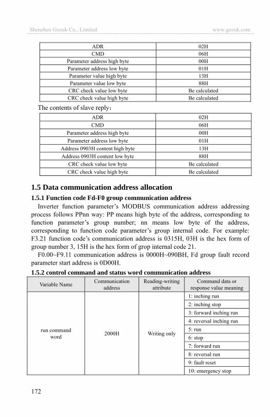
172
ADR 02H CMD 06H
Parameter address high byte 00H Parameter address low byte 01H Parameter value high byte 13H Parameter value low byte 88H
CRC check value low byte Be calculated CRC check value high byte Be calculated
The contents of slave replyADR 02H CMD 06H
Parameter address high byte 00H Parameter address low byte 01H
Address 0903H content high byte 13H Address 0903H content low byte 88H
CRC check value low byte Be calculated CRC check value high byte Be calculated
1.5 Data communication address allocation 1.5.1 Function code Fd-F0 group communication address
Inverter function parameter’s MODBUS communication address addressing process follows PPnn way: PP means high byte of the address, corresponding to function parameter’s group number; nn means low byte of the address, corresponding to function code parameter’s group internal code. For example: F3.21 function code’s communication address is 0315H, 03H is the hex form of group number 3, 15H is the hex form of grop internal code 21.
F0.00~F9.11 communication address is 0000H~090BH, Fd group fault record parameter start address is 0D00H. 1.5.2 control command and status word communication address
Variable Name Communication address
Reading-writing attribute
Command data or response value meaning
run command word 2000H Writing only
1: inching run 2: inching stop 3: forward inching run 4: reversal inching run 5: run 6: stop 7: forward run 8: reversal run 9: fault reset 10: emergency stop
Shenzhen Gozuk Co., Limited www.gozuk.com---------------------------------------------------------------------------------------------------------------------------
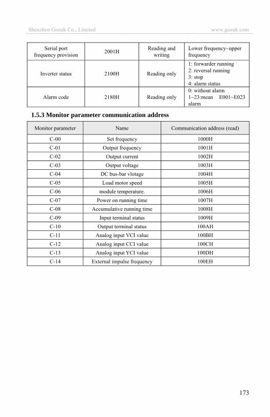
173
Serial port frequency provision 2001H Reading and
writing Lower frequency~upper frequency
Inverter status 2100H Reading only
1: forwarder running 2: reversal running 3: stop 4: alarm status
Alarm code 2180H Reading only 0: without alarm 1~23:mean E001~E023 alarm
1.5.3 Monitor parameter communication address
Monitor parameter Name Communication address (read)
C-00 Set frequency 1000H C-01 Output frequency 1001H C-02 Output current 1002H C-03 Output voltage 1003H C-04 DC bus-bar vlotage 1004H C-05 Load motor speed 1005H C-06 module temperature. 1006H C-07 Power on running time 1007H C-08 Accumulative running time 1008H C-09 Input terminal status 1009H C-10 Output terminal status 100AH C-11 Analog input VCI value 100BH C-12 Analog input CCI value 100CH C-13 Analog input YCI value 100DH C-14 External impulse frequency 100EH
Shenzhen Gozuk Co., Limited www.gozuk.com---------------------------------------------------------------------------------------------------------------------------

174
1.6 Communication error processingInverter receiving data packet detection error, it finds reading&writing
parameter address or parameter value invalid, so reply to the host with communication error response packet. Communication error response packet (host command code +80H) as command code, with 1 byte error code.
Format for communication error response packet as follows:
ADR 01H
CMD 83H/86H
Communication error code 01H~06H (for details, please check below table)
Low byte of CRC checksum Obtain by calculating
High byte of CRC checksum Obtain by calculating
Meaning for each communication error code value as follows:
Communication error code value Type of communication error
0x01 CRC checksum error
0x02 Command code illegal
0x03 Register address visited illegal
0x04 Value to register illegal
0x05 Not allow to modify parameters
0x06 Register number read illegal
Shenzhen Gozuk Co., Limited www.gozuk.com---------------------------------------------------------------------------------------------------------------------------
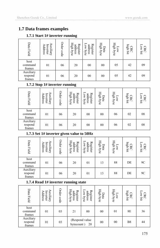
175
1.7 Data frames examples 1.7.1 Start 1# inverter running
host command
frames 01 06 20 00 00 05 42 09
Auxiliary respond frames
01 06 20 00 00 05 42 09
1.7.2 Stop 1# inverter running
host command
frames 01 06 20 00 00 06 02 08
Auxiliary respond frames
01 06 20 00 00 06 02 08
1.7.3 Set 1# inverter given value to 50Hz
host command
frames 01 06 20 01 13 88 DE 9C
Auxiliary respond frames
01 06 20 01 13 88 DE 9C
1.7.4 Read 1# inverter running state
host command
frames 01 03 21 00 00 01 8E 36
Auxiliary respond frames
01 03 (Respond value bytecount ) 20
00 00 B8 44
Shenzhen Gozuk Co., Limited www.gozuk.com---------------------------------------------------------------------------------------------------------------------------
176
1.8 CRC checksum mode CRC checksum value calculating function written by C language is as
follows:unsigned int cal_crc_value (unsigned char *pval, unsigned char len) { unsigned int crc_value=0xFFFF; unsigned int i;
while(len--) { crc_value ^= *pval++; for(i=0; i<8; i++) { if(crc_value & 0x0001) { crc_value >>= 1; crc_value ^= 0xA001; } else { crc_value >>= 1; } } } return(crc_value); }
Shenzhen Gozuk Co., Limited www.gozuk.com---------------------------------------------------------------------------------------------------------------------------
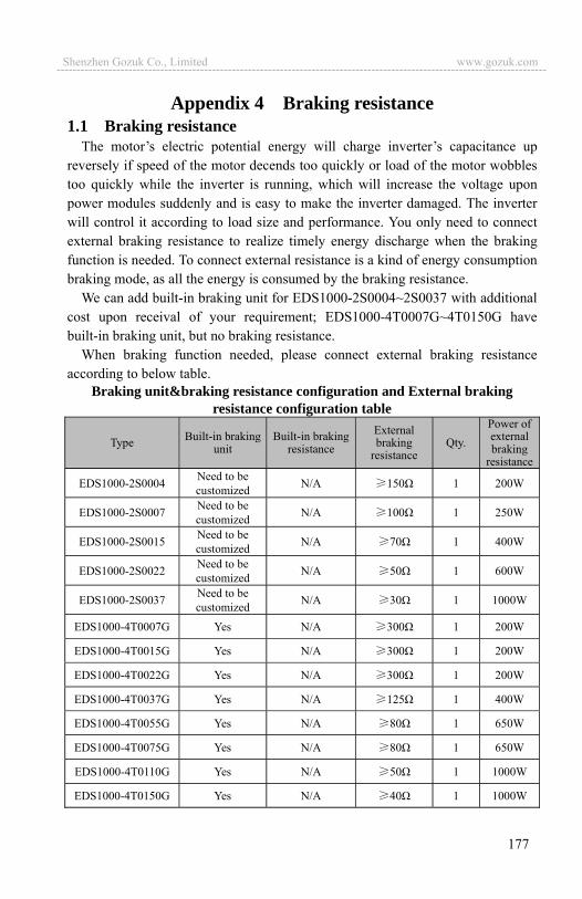
177
Appendix 4 Braking resistance 1.1 Braking resistance
The motor�s electric potential energy will charge inverter�s capacitance up reversely if speed of the motor decends too quickly or load of the motor wobbles too quickly while the inverter is running, which will increase the voltage upon power modules suddenly and is easy to make the inverter damaged. The inverter will control it according to load size and performance. You only need to connect external braking resistance to realize timely energy discharge when the braking function is needed. To connect external resistance is a kind of energy consumption braking mode, as all the energy is consumed by the braking resistance.
We can add built-in braking unit for EDS1000-2S0004~2S0037 with additional cost upon receival of your requirement; EDS1000-4T0007G~4T0150G have built-in braking unit, but no braking resistance.
When braking function needed, please connect external braking resistance according to below table.
Braking unit&braking resistance configuration and External braking resistance configuration table
Type Built-in braking unit
Built-in braking resistance
External braking
resistance Qty.
Power of external braking
resistance
EDS1000-2S0004 Need to be customized N/A 150 1 200W
EDS1000-2S0007 Need to be customized N/A 100 1 250W
EDS1000-2S0015 Need to be customized N/A 70 1 400W
EDS1000-2S0022 Need to be customized N/A 50 1 600W
EDS1000-2S0037 Need to be customized N/A 30 1 1000W
EDS1000-4T0007G Yes N/A 300 1 200W
EDS1000-4T0015G Yes N/A 300 1 200W
EDS1000-4T0022G Yes N/A 300 1 200W
EDS1000-4T0037G Yes N/A 125 1 400W
EDS1000-4T0055G Yes N/A 80 1 650W
EDS1000-4T0075G Yes N/A 80 1 650W
EDS1000-4T0110G Yes N/A 50 1 1000W
EDS1000-4T0150G Yes N/A 40 1 1000W
Shenzhen Gozuk Co., Limited www.gozuk.com---------------------------------------------------------------------------------------------------------------------------