Embed Size (px)
Citation preview

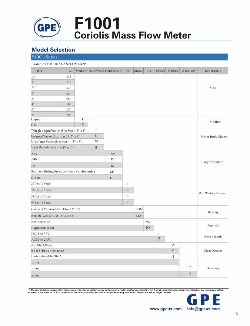
F1001 Coriolis Mass Flow Meter uses two parallel arranged pipes which are rotated at their resonant frequency by coils. Any mass flow passing through the tubes will generate coriolis forces which appear whenever a mass moves radially in a rotating system. The forces have opposed effects on the inlet and outlet sides, they slightly deform the pipes. The excursion of the pipes is detected by sensors on the inlet and outlet side.The phase shift between the rotational frequencies of both pipes are proportional to the mass flow rate. The resonant frequency of both pipes changes in accordance with the density of the medium. This effect determines the density. Using one sensor density and temperature can also be measured.The extent of deformation of the pipes depends on temperature.Therefore the temperature is measured for compensation purposes.
Fluid Reactive Force(Intlet)
The specifications contained herein are subject to change without notice and any user of said specifications should verify from the manufacturer that the specifications are currently in effect. Otherwise, the manufacturer assumes no responsibility for the use of specifications which may have been changed and are no longer in effect.
Outlet
Inlet Twist
AxisOutletSide
Inlet Side
Transmitter
Connection Flange
Housing
Magnet
VF1001-002.00-13/04
GPE www.gpeus.com [email protected]
Oscillating Flow Tube, Response To Flow
Size Allowable Flow Range Normal Flow Range
for Accuracy 0.2% & 0.5% Stability of Zero
Point (kg/h)
Size Allowable Flow Range Normal Flow Range
for Accuracy 0.2% & 0.5% Stability of Zero
Point (kg/h)
General Version
Micro-bend Version
Normal Flow Rangefor Accuracy 0.1% & 0.15%
Normal Flow Rangefor Accuracy 0.1% & 0.15%
Fluid Reactive Force(Outlet)

The specifications contained herein are subject to change without notice and any user of said specifications should verify from the manufacturer that the specifications are currently in effect. Otherwise, the manufacturer assumes no responsibility for the use of specifications which may have been changed and are no longer in effect.
DSP transmitter with superior accuracy 0.1%20:1 turndown ratio
5 to 8 calibration points Mass flow, density, temperature and volume flow
can be measured at the same timeImproved startup and availability with simple
commissioning and reduced risk No moving parts result in no maintenanceInstall anywhere with no flow conditioning or
straight pipe required
Flow Range: 16 kg/h to 2500 t/hConnection: Flange/Thread
Operating Pressure:CustomizedProcess Temperature: Up to 662 F (up to +350 )Body Material: 304 Stainless Steel
Measuring Tube Material: 316L Stainless Steel Ambient Temperature: -40 to 131 F (-40 to +55 ) Working Humidity: (5% to 95%) RH@77 F (+25 ) Accuracy: Up to 0.1%Repeatability: 0.05%Protection: IP 65 (IP 67 optional) Approvals: CE, Exd (ib)II CT4 RS 485 OutputPulse Output: 0 to 10 kHz, 0.001%F.S/Current Output: 4 to 20mA, 0.005%F.S/ ,Power Supply: 85 to 265 VAC, 18 to 36 VDCDensity Measuring:
Range: 0.2 to 2.0 kg/l, Repeatability: 0.001 kg/l
GPEwww.gpeus.com [email protected]
pharmaceutical industry,
medium
medium
, CNG and LNG.

The diagram shows typical values.Individual values may be taken from the calibration records supplied with each meter. 0 10 20 30 40 50 60 70 80 90
Flow in %
Accuracy =Zero Stability
Measuring value100 Basic Error
Accuracy
Repeatability
Accuracy is calculated based on the water measurement under the condition of +20 to 25 and 0.1MPa to 0.2MPa.
Density Range
Basic Error
Repeatability
The specifications contained herein are subject to change without notice and any user of said specifications should verify from the manufacturer that the specifications are currently in effect. Otherwise, the manufacturer assumes no responsibility for the use of specifications which may have been changed and are no longer in effect.
-
-
-
-
-
GPE www.gpeus.com [email protected]

Coriolis Mass Flowmeter Dimension and Weight
Figure A.1 Outline dimensions
Compact version – Figure A.1.1, A.1.2 (F1001-T and F1001-U series) Remote version – Figure A.1.3, A.1.4(F1001-T and F1001-U series)
The specifications contained herein are subject to change without notice and any user of said specifications should verify from the manufacturer that the specifications are currently in effect. Otherwise, the manufacturer assumes no responsibility for the use of specifications which may have been changed and are no longer in effect.
G P E
H1
LL
H1
L1L1
H
D2
hb
BD1 d1
D
nx
d
PN = 1.6 - 4.0 MPa
hb
nx
dd1D
D1D2
BРN = 6.4 MPa
h2D6
A.1.1 A.1.2
A.1.3 A.1.4
H
B
B
C max130
L1
L
H2H
12531
2 115
Е
175
B
L1
125
312
115
ЕL
H2H
110
4 holes 8,5
Е
B
175
130
h2

Coriolis Mass Flowmeter
Table A.1 – Outline dimensions and weight
L, mm Weight, kg Process connection size Figure 1.6-4.0
MPa 6.4
MPa
L1, mm
H, mm
H1, mm
H2, mm
С max, mm * А.1.1,
А.1.2А.1. 3, А.1.4
DN10,3/8 inch А.1.1; А.1.3 150 170 350 290 260 190 95 11 14 DN15,1/2 inch А.1.1; А.1.3 180 194 350 300 260 190 95 11 14
DN25,1 inch А.1.1; А.1.3 200 248 450 420 280 210 115 15 18
DN40,1 1/2 inch А.1.2; А.1.4 520 547 470 660 280 210 150 30 33
DN50,2 inch А.1.2; А.1.4 558 588 550 730 290 220 165 35 38
DN80,3 inch А.1.2; А.1.4 780 808 710 1040 320 250 205 80 83
DN100,4 inch А.1.2; А.1.4 920 948 860 1140 350 280 416 185 188
DN150,6 inch А.1.2; А.1.4 1100 1140 1050 1520 380 310 440 320 323
DN200,8 inch А.1.2; А.1.4 1364 1410 1160 1655 420 350 535 625 628
* Overall width of the body, excluding transmitter
Table A.2 – Flowmeter flange dimensions
Process connection size
PN, MPa
d1, mm
D6, mm
D2, mm
D1, mm D, mm b, mm h, mm h2,
mm n d, mm
1.6; 2.5; 4 10 ̶ 40 60 90 12 2 ̶ 4 14 DN10,3/8 inch 6.4 8 35 41 70 100 16 4 3 4 14 1.6; 2.5; 4 15 ̶ 46 65 95 12 2 ̶ 4 14 DN15,1/2 inch 6.4 11.6 40 46 75 105 16 4 3 4 14 1.6; 2.5; 4 27.3 ̶ 65 85 115 13 3 ̶ 4 14 DN25,1 inch 6.4 24.8 58 65 100 140 20 4 3 4 18 1.6; 2.5; 4 41.1 ̶ 85 110 150 15 3 ̶ 4 18 DN40,1 1/2 inch 6.4 37 76 84 125 170 22 4 3 4 22 1.6; 2.5; 4 52.3 ̶ 99 125 165 18 2 ̶ 4 18 DN50,2 inch 6.4 47 88 99 135 180 22 4 3 4 22 1.6; 2.5; 4 79.5 ̶ 132 160 200 20 2 ̶ 8 18 DN80,3 inch 6.4 77 121 132 170 215 24 4 3 8 22 1.6; 2.5; 4 101.7 ̶ 156 190 235 21 3 ̶ 8 22 DN100,4 inch 6.4 94 150 156 200 250 25.5 4.5 3.5 8 26 1.6; 2.5; 4 154 ̶ 211 250 300 26 2 ̶ 8 26 DN150,6 inch 6.4 142 204 211 280 345 31.5 4.5 3.5 8 33 1.6; 2.5; 4 200 ̶ 285 320 375 35 3 ̶ 12 30 DN200,8 inch 6.4 198 260 284 345 415 37.5 4.5 3.5 12 36
The specifications contained herein are subject to change without notice and any user of said specifications should verify from the manufacturer that the specifications are currently in effect. Otherwise, the manufacturer assumes no responsibility for the use of specifications which may have been changed and are no longer in effect.
G P E

312
115
125
Н2 Н
1
175
Н
Н
Coriolis Mass Flowmeter Dimension and Weight
L
L B
L1 L1
A.2.1 A.2.2
Figure A.2 Outline dimensions ( F1001-M series) Integral type – Figure A.2.1 Separate type – Figure A.2.2
Table A.3 – Outline dimensions and weight
L, mm Weight, kg Process connection size Figure 1.6-4.0
MPa 6.4
MPa
L1, mm
H, mm
H1, mm
H2, mm
С max, mm * A.2.1
A.2.2 DN10, 3/8 inch A.2 360 374 240 180 290 220 95 11 14
DN15, 1/2 inch A.2 400 414 280 184 290 220 115 15 18 DN25,1 inch A.2 500 536 360 250 300 230 150 30 33
DN40, 1 1/2 inch A.2 600 634 460 300 310 240 165 35 38
DN50, 2 inch A.2 800 828 640 410 320 250 205 80 83
DN80, 3 inch A.2 900 928 700 490 350 280 416 185 188
DN100, 4 inch A.2 1130 1156 860 660 370 290 440 320 323 DN150, 6 inch A.2 1410 1450 1200 900 400 330 535 625 628
DN200, 8 inch A2 1800 1844 1450 1170 420 350 580 820 823 * Overall width of the body, excluding transmitter
The specifications contained herein are subject to change without notice and any user of said specifications should verify from the manufacturer that the specifications are currently in effect. Otherwise, the manufacturer assumes no responsibility for the use of specifications which may have been changed and are no longer in effect.
GPE

Coriolis Mass Flowmeter
D2
hb
D1
d1D
nx
d
Figure A.2 Outline dimensions of connection kit flanges Table A.4 – Connection kit flange dimensions and weight
DN(mm), inch PN, MPa
d1, mm
D2, mm
D1, mm
D, mm
b, mm
h, mm n d,
mm Weight,
kg
1.6; 2.5; 4 10 40 60 90 12 2 4 14 0.7 DN10,3/8inch 6.4 8 34 70 100 16 4 4 14 1.0 1.6; 2.5; 4 15 46 65 95 12 2 4 14 0.8 DN15, 1inch 6.4 11.6 39 75 105 16 4 4 14 1.1 1.6; 2.5; 4 27.3 65 85 115 13 3 4 14 1.2 DN25, 1inch 6.4 24.8 57 100 140 20 4 4 18 2.3 1.6; 2.5; 4 41.1 85 110 150 13 3 4 18 2.1 DN40, 1 1/2inch 6.4 37 75 125 170 22 4 4 22 3.7 1.6; 2.5; 4 52.3 99 125 165 18 2 4 18 2.8 DN50,2 inch 6.4 47 87 135 180 22 4 4 22 4.6 1.6; 2.5; 4 79.5 132 160 200 20 2 8 18 4.8 DN80, 3 inch 6.4 77 120 170 215 24 4 8 22 7.2 1.6; 2.5; 4 101.7 156 190 235 21 3 8 22 7.0 DN100, 4 inch 6.4 94 149 200 250 25.5 4.5 8 26 10.7 1.6; 2.5; 4 154 211 250 300 26 2 8 26 13.2 DN150, 6inch 6.4 142 203 280 345 31.5 4.5 8 33 25.4 1.6; 2.5; 4 200 285 320 375 35 3 12 30 24.0 DN200, 8inch 6.4 198 259 345 415 37.5 4.5 12 36 38.5
The specifications contained herein are subject to change without notice and any user of said specifications should verify from the manufacturer that the specifications are currently in effect. Otherwise, the manufacturer assumes no responsibility for the use of specifications which may have been changed and are no longer in effect.
G P E

L
Coriolis Mass Flowmeter Dimension and Weight
Figure A.3.1 Outline dimensions ( F1001-S series)
Table A.3.1 – Outline dimensions and weight
Process connection size Figure
L, mm L1, mm
H, mm
H1, mm
С max, mm *
Weight, kg
1.6-4.0 MPa
6.4 MPa A.3
DN50, 2 inch A.3 800 828 450 200 315 205 30 DN80, 3 inch A.3 935 950 645 200 335 416 60
* Overall width of the body, excluding transmitter Tri-clamp
Figure A.3.2 Outline dimensions ( F1001-S series) Table A.3.2 – Outline dimensions and weight
Process connection size Figure
L, mm L1, mm
H, mm
H1, mm
С max, mm *
Weight, kg
1.6-4.0 MPa
6.4 MPa A.3
DN50, 2 inch A.4 800 828 450 200 315 205 30 DN80, 3 inch A.4 935 950 645 200 335 416 60
The specifications contained herein are subject to change without notice and any user of said specifications should verify from the manufacturer that the specifications are currently in effect. Otherwise, the manufacturer assumes no responsibility for the use of specifications which may have been changed and are no longer in effect.
GPE