Embed Size (px)
Citation preview
GPM
GPMGlobal Precipitation Measurement
JPL Planned Contribution to GPM
Eastwood Im, Ziad S. HaddadJPL5/16/2001
GPMGlobal Precipitation Measurement
JPL Planned Contribution to GPM
Eastwood Im, Ziad S. HaddadJPL5/16/2001
E. Im, Z. Haddad
IntroductionIntroduction
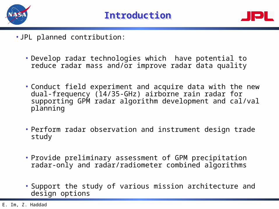
•JPL planned contribution:
• Develop radar technologies which have potential to reduce radar mass and/or improve radar data quality
• Conduct field experiment and acquire data with the new dual-frequency (14/35-GHz) airborne rain radar for supporting GPM radar algorithm development and cal/val planning
• Perform radar observation and instrument design trade study
• Provide preliminary assessment of GPM precipitation radar-only and radar/radiometer combined algorithms
• Support the study of various mission architecture and design options
E. Im, Z. Haddad
1: Develop Spaceborne Precipitation Radar Technologies
1: Develop Spaceborne Precipitation Radar Technologies
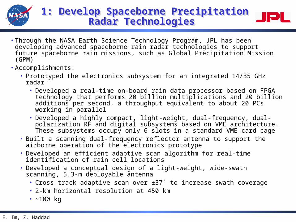
• Through the NASA Earth Science Technology Program, JPL has been developing advanced spaceborne rain radar technologies to support future spaceborne rain missions, such as Global Precipitation Mission (GPM)
• Accomplishments:• Prototyped the electronics subsystem for an integrated 14/35 GHz radar
• Developed a real-time on-board rain data processor based on FPGA technology that performs 20 billion multiplications and 20 billion additions per second, a throughput equivalent to about 20 PCs working in parallel
• Developed a highly compact, light-weight, dual-frequency, dual-polarization RF and digital subsystems based on VME architecture. These subsystems occupy only 6 slots in a standard VME card cage
• Built a scanning dual-frequency reflector antenna to support the airborne operation of the electronics prototype
• Developed an efficient adaptive scan algorithm for real-time identification of rain cell locations
• Developed a conceptual design of a light-weight, wide-swath scanning, 5.3-m deployable antenna
• Cross-track adaptive scan over ±37˚ to increase swath coverage• 2-km horizontal resolution at 450 km• ~100 kg
Advanced Precipitation Radar Technologies
Advanced Precipitation Radar Technologies
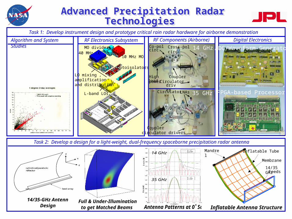
Algorithm and System Studies
10 MHz MO
L-band LOs
40 MHz LOMO dividers
Optoisolators
LO mixing ,amplificationand distribution
RF Electronics Subsystem RF Components (Airborne)
Task 1: Develop instrument design and prototype critical rain radar hardware for airborne demonstration
Digital Electronics Subsystem
CouplerCirculator
High power
Co-pol Cross-pol circ.
circulator drivers
LNAs
loaddriver
Coupler
Circulator 35 GHz
14 GHzcirc.
FPGA-based Processor
ADC/Waveform Generator
14/35-GHz AntennaDesign Antenna Patterns at 0˚ Scan
35 GHz
14 GHz
Membrane
Inflatable TubeMandrel
14/35 GHz
Task 2: Develop a design for a light-weight, dual-frequency spaceborne precipitation radar antenna
Inflatable Antenna Structure
Feeds
Full & Under-Illuminationto get Matched Beams
E. Im, Z. Haddad
2: Airborne Precipitation Radar Experiments
2: Airborne Precipitation Radar Experiments
•The Airborne Rain Mapping Radar (ARMAR) was developed in early 1990’s
• Operated on DC-8 with TRMM PR geometry and frequency• also provides dual-polarization and Doppler capabilities• Field experiments with ARMAR
• TOGA-COARE (1993)• TEFLUN-B/CAMEX3 (1998)• KWAJEX (1999)
•The new dual-frequency airborne rain radar will participate in CAMEX-4 experiment (8-9/2001)
• Will operate on DC-8 with the planned GPM radar geometry and frequency
• Will support GPM radar algorithm development and calibration/validation planning
•Current status• The radar ground testing will be completed in May’01• Airborne engineering flights (20 hours) are scheduled for June’01
Examples of ARMAR Measurements and Science Results
Examples of ARMAR Measurements and Science Results
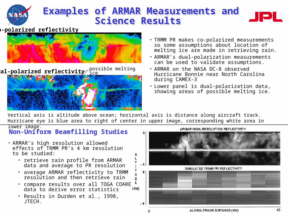
Vertical axis is altitude above ocean; horizontal axis is distance along aircraft track. Hurricane eye is blue area to right of center in upper image, corresponding white area in lower image.
possible melting ice
• ARMAR’s high resolution allowed effects of TRMM PR’s 4 km resolution to be studied:
• retrieve rain profile from ARMAR data and average to PR resolution
• average ARMAR reflectivity to TRMM resolution and then retrieve rain
• compare results over all TOGA COARE data to derive error statistics
• Results in Durden et al., 1998, JTECH.
Dual-polarized reflectivity
Co-polarized reflectivity
• TRMM PR makes co-polarized measurements so some assumptions about location of melting ice are made in retrieving rain.
• ARMAR’s dual-polarization measurements can be used to validate assumptions.
• ARMAR on the NASA DC-8 observed Hurricane Bonnie near North Carolina during CAMEX-3
• Lower panel is dual-polarization data, showing areas of possible melting ice.
Non-Uniform Beamfilling Studies
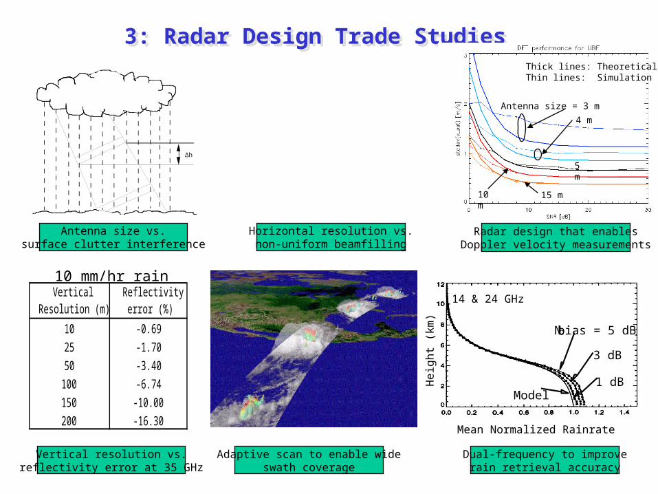
3: Radar Design Trade Studies 3: Radar Design Trade Studies
∆h
Antenna size = 3 m
4 m
5 m
10 m 15 m
Thick lines: TheoreticalThin lines: Simulation
He
igh
t (k
m)
Mean Normalized Rainrate
14 & 24 GHz
3 dB
No bias = 5 dB
1 dBModel
Horizontal resolution vs.non-uniform beamfilling
Radar design that enablesDoppler velocity measurements
Vertical resolution vs.reflectivity error at 35 GHz
Adaptive scan to enable wideswath coverage
Dual-frequency to improverain retrieval accuracy
Antenna size vs.surface clutter interference
Vertical Resolution (m)
Reflectivity error (%)
10 -0.6925 -1.7050 -3.40
100 -6.74150 -10.00200 -16.30
10 mm/hr rain
E. Im, Z. Haddad
4: Retrieval Algorithms 4: Retrieval Algorithms
•Main goals:• water cycle => surface precipitation (benchmarks: GPI, SSM/I)• parametrize convection => latent heating profiles
•Main problems in the estimation process:• differentiating between (liquid) rain, hail, graupel, aggregates, snow• unknown Drop Size Distribution• radar attenuation
•Approach: Develop preliminary assessment of radar algorithms• Compile a representative cloud-model simulated storm database and
synthesize corresponding “observations”• Synthesize 35-GHz “data” from TRMM estimated profiles• Analyze dual-frequency wind-profiler data to estimate DSD and
synthesize corresponding “observations”• Implement various algorithms, apply them to the data and compile
performance statistics
Principal Component Analysis of Vertical Hydrometeor Profiles
Principal Component Analysis of Vertical Hydrometeor Profiles
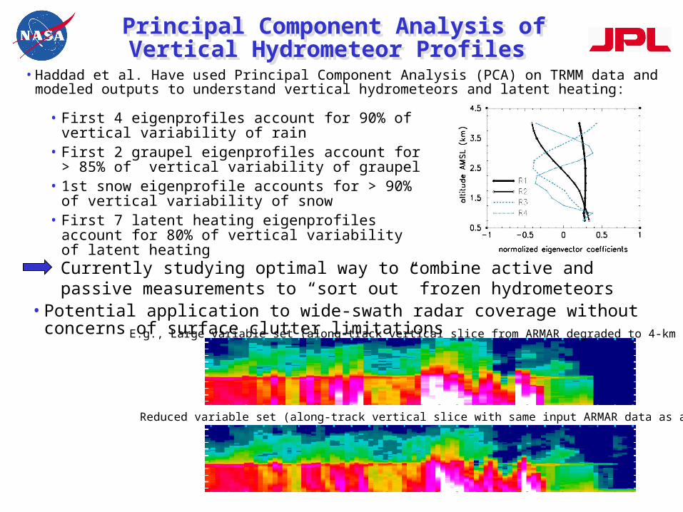
• First 4 eigenprofiles account for 90% of vertical variability of rain
• First 2 graupel eigenprofiles account for > 85% of vertical variability of graupel
• 1st snow eigenprofile accounts for > 90% of vertical variability of snow
• First 7 latent heating eigenprofiles account for 80% of vertical variability of latent heating
Currently studying optimal way to combine active and passive measurements to “sort out” frozen hydrometeors
•Haddad et al. Have used Principal Component Analysis (PCA) on TRMM data and modeled outputs to understand vertical hydrometeors and latent heating:
•Potential application to wide-swath radar coverage without concerns of surface clutter limitations
Reduced variable set (along-track vertical slice with same input ARMAR data as above)
E.g., Large variable set (along-track vertical slice from ARMAR degraded to 4-km resolution)
E. Im, Z. Haddad
Precipitation Retrieval with Radar Algorithm
Precipitation Retrieval with Radar Algorithm
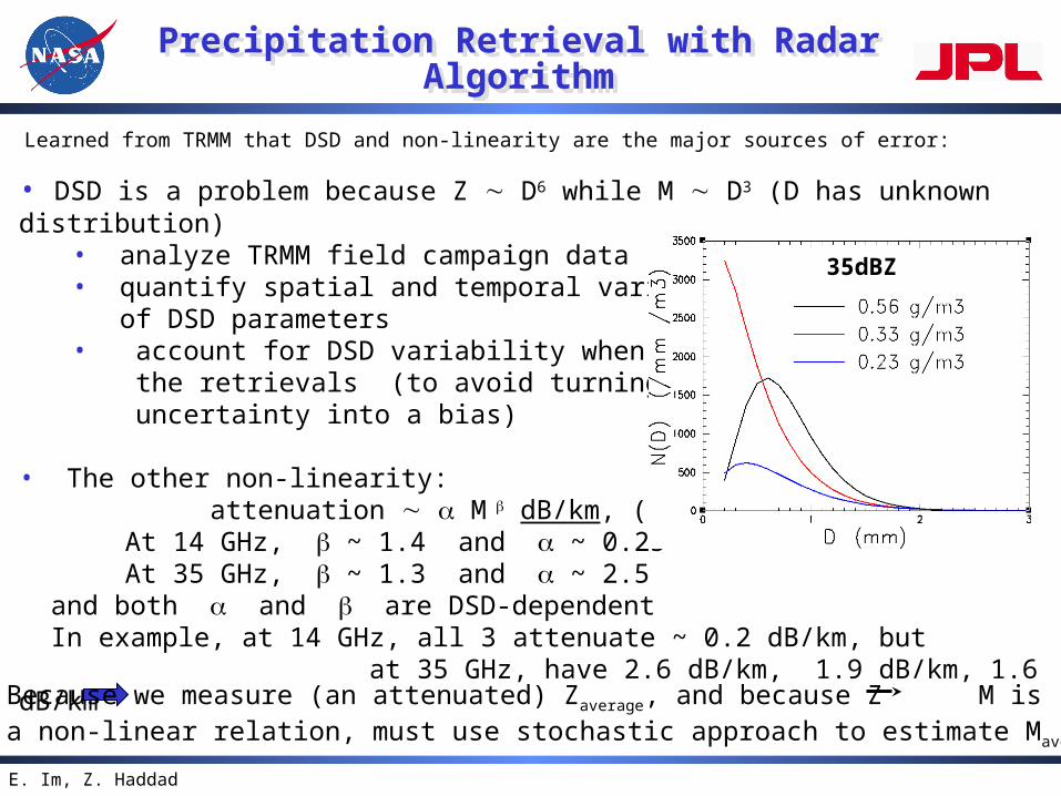
• DSD is a problem because Z D6 while M D3 (D has unknown distribution) • analyze TRMM field campaign data • quantify spatial and temporal variability of DSD parameters• account for DSD variability when performing the retrievals (to avoid turning a “white” uncertainty into a bias)
• The other non-linearity: attenuation M dB/km, (M in g/m3)
At 14 GHz, ~ 1.4 and ~ 0.25At 35 GHz, ~ 1.3 and ~ 2.5
and both and are DSD-dependent In example, at 14 GHz, all 3 attenuate ~ 0.2 dB/km, but at 35 GHz, have 2.6 dB/km, 1.9 dB/km, 1.6 dB/km
Learned from TRMM that DSD and non-linearity are the major sources of error:
Because we measure (an attenuated) Zaverage, and because Z M isa non-linear relation, must use stochastic approach to estimate Maverage
35dBZ
E. Im, Z. Haddad
5: Support Mission and SystemConcept Tradeoffs
5: Support Mission and SystemConcept Tradeoffs
•JPL's Rapid Concurrent Engineering Design Team works closely with GSFC’s IMDC will support GPM on:
• Trade study of various mission architecture concepts• Review of the eventual baseline mission concept• Develop impact metrics on technology utilization
•Identify newer technologies which have the potential to reduce cost/risk, and/or improve science data return. Examples include: Autonomous station-keeping to reduce operations and
maintain precise altitudes or repeat passes Advanced GPS technologies for precision position
knowledge Autonomous mission planning technologies for rapid,
automated mission planning and coverage assessment
E. Im, Z. Haddad 1717
Cloud Profiling Radar for the CloudSat Mission
Cloud Profiling Radar for the CloudSat Mission
Horiz. Res.
Vert. Res.
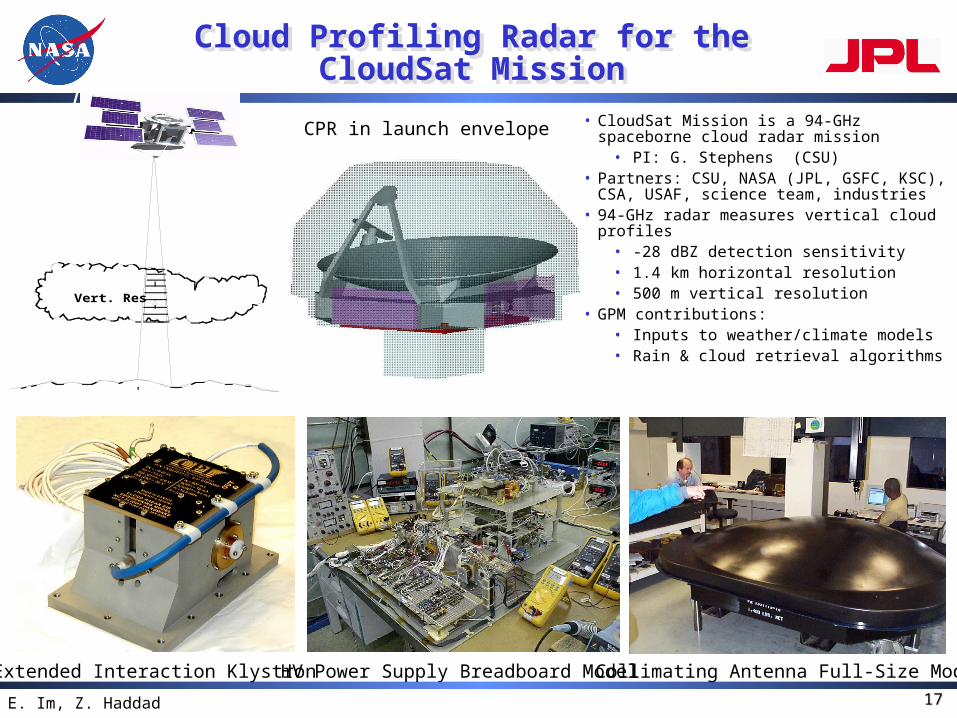
Collimating Antenna Full-Size Mode
CPR in launch envelope
Extended Interaction Klystron HV Power Supply Breadboard Model
• CloudSat Mission is a 94-GHz spaceborne cloud radar mission
• PI: G. Stephens (CSU)• Partners: CSU, NASA (JPL, GSFC, KSC),
CSA, USAF, science team, industries• 94-GHz radar measures vertical cloud
profiles• -28 dBZ detection sensitivity• 1.4 km horizontal resolution• 500 m vertical resolution
• GPM contributions:• Inputs to weather/climate models• Rain & cloud retrieval algorithms