Embed Size (px)
DESCRIPTION
GPRS Design and Optimisation Report Ver 1.
Citation preview

Wireless Facilities International Limited74 North Street w Guildford GU1 4AW w United Kingdom
Tel +44 (0) 1483 400900 w Fax +44 (0) 1483 400909 w http://www.wfinet.com
GPRS RF Design and Optimisation
November 2001
Version 1.0
GPRS RF Optimization Report ver 1.0
© Copyright 2000 Wireless Facilities, Inc. - EMEA Confidential- Internal Use Only1
Executive Summary
This report endeavors to give a guideline to optimise a GPRS network. There aredifferent scenarios in which GPRS services are required. One that requires a new designof a GSM network having the GPRS services in mind and the other a migration from anexisting GSM to GPRS network.
The densed urban area of Paris is taken as an example for this study. As a result a linkbudget is created for this design and two coverage scenarios are created which showsthe need for optimisation of such a network.
Finally for capacity dimensioning has been carried out to show the capacity calculationsand assumptions for such a network.

GPRS RF Optimization Report ver 1.0
© Copyright 2000 Wireless Facilities, Inc. - EMEA Confidential- Internal Use Only2
Document History
Version Prepared by Edited by Date Modifications (Do notWrite in this section)
V1.0 Hilda Correia Payam Taaghol 11/13/01Luis Rivilla
Maseeh AzhandMo Eskici
Ravi GovindasamySasan Fahim
Lauro OrtigozaHedayat Azad

GPRS RF Optimization Report ver 1.0
© Copyright 2000 Wireless Facilities, Inc. - EMEA Confidential- Internal Use Only3
1 Abbreviations ............................................................................................................. 52 Introduction and Background .................................................................................. 8
2.1 WHAT IS GPRS?..................................................................................................... 82.2 GPRS ARCHITECTURE............................................................................................ 92.3 NETWORK ELEMENTS OF THE BASE STATION SYSTEM (BSS)................................ 10
2.3.1 Base station controllers (BSC) ..................................................................... 102.3.2 Base transceiver stations (BTS)................................................................... 10
2.4 NETWORK ELEMENTS OF THE GPRS SWITCHING SUBSYSTEM (GSS).................... 102.4.1 Serving GPRS support node (SGSN) .......................................................... 102.4.2 Gateway GPRS support node (GGSN)........................................................ 112.4.3 Home location register (HLR) (for GPRS PLMN)......................................... 112.4.4 Authentication center (AC)............................................................................ 112.4.5 Visitor location register (VLR)....................................................................... 11
2.5 MOBILE STATION FOR GPRS ................................................................................. 122.5.1 Class-A.......................................................................................................... 122.5.2 Class-B.......................................................................................................... 122.5.3 Class-C ......................................................................................................... 12
2.6 INTERNAL GPRS PLMN INTERFACES.................................................................... 122.6.1 Abis-interface................................................................................................ 122.6.2 Gb-interface .................................................................................................. 132.6.3 Gd-interface .................................................................................................. 132.6.4 Gf-interface ................................................................................................... 132.6.5 Gn-interface .................................................................................................. 132.6.6 Gp-interface .................................................................................................. 132.6.7 Gr-interface................................................................................................... 132.6.8 Gs-interface .................................................................................................. 13
2.7 EXTERNAL GPRS PLMN INTERFACES................................................................... 142.7.1 Gi-interface (GPRS PLMN to Internet) ......................................................... 14
2.8 THE TRANSMISSION PLANE.................................................................................... 142.8.1 Signaling Plane ............................................................................................. 15
2.9 THE AIR INTERFACE............................................................................................... 162.9.1 Physical Layer............................................................................................... 162.9.2 Medium Access Control................................................................................ 192.9.3 Radio Resource Management...................................................................... 192.9.4 Mobility Management.................................................................................... 19
2.10 GPRS OPERATION ................................................................................................ 202.10.1 Mobile Originated Packet Transfer............................................................... 212.10.2 Mobile Terminated Packet Transfer ............................................................. 22
2.11 WHERE IS GPRS NOW? ........................................................................................ 233 GPRS Radio Design and Optimisation Methodology.......................................... 28
3.1 VISIBILITY OF NETWORK PERFORMANCE................................................................. 293.2 UNKNOWN SERVICE REQUIREMENTS ...................................................................... 293.3 DESIGN CASES ...................................................................................................... 30
3.3.1 New GSM Network Design with GPRS........................................................ 303.3.2 Migration from GSM to GPRS network......................................................... 31
4 GPRS Link Budgets ................................................................................................. 324.1 MAXIMUM ALLOWABLE PATH LOSS......................................................................... 344.2 CELL SIZE ESTIMATION .......................................................................................... 354.3 CELL COUNT ESTIMATION ...................................................................................... 36
5 Considerations in the GPRS link budgets ............................................................ 37

GPRS RF Optimization Report ver 1.0
© Copyright 2000 Wireless Facilities, Inc. - EMEA Confidential- Internal Use Only4
5.1 RX SENSITIVITY VS CODING SCHEME..................................................................... 375.2 BODY LOSS ........................................................................................................... 375.3 2 DB C/I DEGRADATION IN THE DOWNLINK............................................................. 385.4 CODING SCHEMES VS CLUTTERS .......................................................................... 38
6 Coverage Analysis ................................................................................................... 396.1 COVERAGE CASE STUDY 1..................................................................................... 39
6.1.1 GSM Coverage for Paris within the periphery area...................................... 396.1.2 GPRS Coverage for Paris within the periphery area for CS1...................... 416.1.3 GPRS Coverage for Paris within the periphery area for CS2...................... 436.1.4 GPRS Coverage for Paris within the periphery area for CS3...................... 456.1.5 GPRS coverage for Paris within the periphery area for CS4..................... 47
6.2 COVERAGE CASE STUDY 2 .................................................................................... 496.2.1 GSM Coverage for Paris within the periphery area with 240 sites .............. 496.2.2 GPRS Coverage for Paris within the periphery area for CS1 with 240 sites516.2.3 GPRS Coverage for Paris within the periphery area for CS2 with 240 sites536.2.4 GPRS Coverage for Paris within the periphery area for CS3 with 240 sites556.2.5 GPRS Coverage for Paris within the periphery area for CS4 with 240 sites57
7 Capacity Dimensioning ........................................................................................... 597.1 NETWORK PERFORMANCE ..................................................................................... 61
7.1.1 Peak Throughput........................................................................................... 617.2 SYSTEM C/I PROFILE AND MEAN DATA RATE PER CHANNEL .................................. 63
7.2.1 Latency.......................................................................................................... 658 Capacity case study................................................................................................. 67
8.1 CASE ONE: ADDING TRXS WITHOUT CONSIDERING DEDICATED TSLS TO GPRSUSERS............................................................................................................................. 67
8.1.1 GPRS migration ............................................................................................ 688.2 CASE TWO: ADDING TRXS WITH CONSIDERING TWO DEDICATED TSLS TO GPRSUSERS............................................................................................................................. 69
8.2.1 GPRS migration ............................................................................................ 708.3 CASE THREE: ADDING NEW SITES WITH CONSIDERING TWO DEDICATED TSLS TOGPRS USERS ................................................................................................................. 71
8.3.1 GPRS migration ............................................................................................ 719 Mobiles availability................................................................................................... 72
9.1 WORLDWIDE GPRS TERMINALS AND HANDSETS ................................................... 72
GPRS RF Optimization Report ver 1.0
© Copyright 2000 Wireless Facilities, Inc. - EMEA Confidential- Internal Use Only5
1 Abbreviations
ABC Administration and Billing CentreAC Authentication CentreAGCH Access Grant ChannelAPN Access Point NameASN ATM Switching NetworkBCT Basic Craft TerminalBER Bit Error RateBVC BSSGP Virtual ConnectionBVCI BSSGP Virtual Connection IdentifierAMX ATM MultiplexerATM Asynchronous Transfer ModeCCU Channel Coding UnitCCCH Common Control ChannelCS Coding SchemesCT Craft TerminalBG Border GatewayBSS Base Station SystemBSSAP Base Station System Application PartBSSGP Base Station System GPRS ProtocolBSSMAP Base Station System Management Application PartBSC Base Station ControllerBTS Base Transceiver StationCCS7 Common Channel Signalling System No. 7 (equal to SS7)DLCI Data Link Connection IdentifierEIR Equipment Identification RegisterETSI European Telecommunications Standards InstituteEWSD Elektronisches Wählsystem DigitalEWSX Elektronisches Wählsystem ExpressFR Frame RelayFTP File Transfer ProtocolGGSN Gateway GPRS Support NodeGR GPRS RegisterGPRS General Packet Radio ServiceGSM Global system for mobile communicationGSN GPRS Support NodeGTP GPRS Tunnelling ProtocolGTT Global Title TranslationHDLC High Level Data Link Control protocolHLR Home Location RegisterHO HandoverHSCSD High Speed Circuit Switched DataIANA Internet Assigned Numbers AuthorityID IdentifierIF InterfaceIMSI International Mobile Subscriber IdentityIP Internet ProtocolIPv4 Internet Protocol version 4IPv6 Internet Protocol version 6
GPRS RF Optimization Report ver 1.0
© Copyright 2000 Wireless Facilities, Inc. - EMEA Confidential- Internal Use Only6
ISP Internet Service ProviderLA Location AreaLAN Local Area NetworkLIC Line Interface ControllerLLC Logical Link ControlMAC Media Access ControlMAP Mobile Application PartMM Mobility ManagementMP Main ProcessorMP:PD Main Processor for Packet DispatchingMP:SA Main Processor with Standalone CapabilitiesMS Mobile StationMSC Mobil Switching CentreMT Mobile TerminatedNS-VC Network Service Virtual ConnectionNS-VCI Network Service Virtual Connection IdentifierNS-VL Network Service Virtual LinkNUC Nailed Up ConnectionsO&M Operation and MaintenanceOMC Operation and Maintenance CentreOMC-S OMC-Switching SubsystemOS Operation SystemPAGCH Packet Access Grant ChannelPCM Pulse Code ModulationPCU Packet Control UnitPCCCH Packet Common Control ChannelPDTCH Packet Data ChannelPDN Packet Data NetworkPDP Packet Data Protocol, e.g. IP or X.25PDU Protocol Data UnitPLMN Public Land Mobile NetworkPRACH Packet Random Access ChannelPSPDN Packet-Switched Private Data NetworksPTM Point To MultipointPTP Point To PointPTP-CLNS Point To Point - Connection Less Network ServicePTP-CONS Point To Point - Connection Oriented Network ServicePVC Permanent Virtual ConnectionP-TMSI Packet - Temporary Mobile Subscriber IdentityQoS Quality of ServiceRA Routing AreaRIP Routing Information ProtocolRLC Radio Link ControlRSS Radio SubsystemSDU Service Data UnitSGSN Serving GPRS Support NodeSM Short MessageSM-SC Short Message Service CentreSMS-GMSC Short Message Service Gateway MSCSMS-IWMSC Short Message Service Interworking MSCSSNC Signalling System Network Control

GPRS RF Optimization Report ver 1.0
© Copyright 2000 Wireless Facilities, Inc. - EMEA Confidential- Internal Use Only7
SSS Switching SubsystemSTP Signalling Transfer PointTE Terminal EquipmentTCH Traffic ChannelUDI Unrestricted Digital InformationUMTS Universal Mobile Telecommunication SystemVCI Virtual Channel or Circuit IdentifierVLR Visited Location RegisterVPI Virtual Path IdentifierWAN Wide Area Network

GPRS RF Optimization Report ver 1.0
© Copyright 2000 Wireless Facilities, Inc. - EMEA Confidential- Internal Use Only8
2 Introduction and Background
Life styles are changing rapidly and subscribers, including individuals, businesses andcorporate users alike, are expecting more mobile services. Ordering cinema ticketswirelessly, accessing up-to-date traffic information from your car, or viewing video clipsof the latest news will soon become common events in everyday life.
For corporate users, accessing corporate intranets and downloading files quickly andefficiently will become essential business skills. The data application opportunities forbusiness and industry are diverse, including remote equipment management, locationidentification for transportation companies, and remote information access for mobileworkers. Mobile data technology affords added value to life styles and businessprocesses leading to enhanced productivity, reduced costs and an overall increase inefficiency.
The Internet has become a critical resource for millions of people worldwide, with manyindividuals doing their shopping on-line, and corporations sharing information andcommunicating around the globe via their corporate intranets.
The explosive demand for mobile communications and the tremendous growth of theInternet present an exciting opportunity for GSM operators to capture new markets byprovisioning a variety of exciting new data applications. GPRS solution, easy access tohigh-speed data packet services is easily achieved, enabling operators to respondquickly to market demands.
GPRS also presents cost implications as users are likely to pay a monthly charge or payfor the quantity of the data they transfer rather than current billing-by-minute basis oftoday’s GSM network. For people who want to stay on-line for long periods of time anduse devices for Internet browsing, GPRS will almost certainly be cheaper.
2.1 What is GPRS?
GPRS is a packet switched data service in GSM for mobile access to the Internet andother packet data networks (PDN). It provides higher user data rates by using trafficchannel combining and different coding schemes. GPRS allows the service subscriber tosend and receive data in an end-to-end transfer mode without utilizing networkresources in circuit switched mode. Resources are used only in case of datatransmission. This allows volume-dependent charging; i.e. the user only pays for thetransferred data.
The GPRS system provides a basic solution for Internet Protocol (IP) communicationbetween Mobile Stations and Internet Service Hosts (IH) and provides:
• efficient use of scarce radio resources
• a flexible service, with volume-based (or session duration-based)charging
• fast set-up/access time
GPRS RF Optimization Report ver 1.0
© Copyright 2000 Wireless Facilities, Inc. - EMEA Confidential- Internal Use Only9
• efficient transport of packets in the GSM network
• simultaneous GSM and GPRS, co-existence without disturbance
• connectivity to other external packet data networks, using theInternet Protocol.
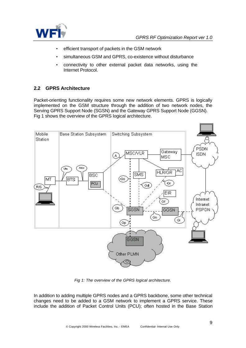
2.2 GPRS Architecture
Packet-orienting functionality requires some new network elements. GPRS is logicallyimplemented on the GSM structure through the addition of two network nodes, theServing GPRS Support Node (SGSN) and the Gateway GPRS Support Node (GGSN).Fig 1 shows the overview of the GPRS logical architecture.
Fig 1: The overview of the GPRS logical architecture.
In addition to adding multiple GPRS nodes and a GPRS backbone, some other technicalchanges need to be added to a GSM network to implement a GPRS service. Theseinclude the addition of Packet Control Units (PCU); often hosted in the Base Station

GPRS RF Optimization Report ver 1.0
© Copyright 2000 Wireless Facilities, Inc. - EMEA Confidential- Internal Use Only10
Subsystems (BSS), mobility management to locate the GPRS Mobile Station (MS), anew air interface for packet traffic, new security features such as ciphering and newGPRS specific signaling.
2.3 Network Elements of the Base Station System (BSS)
2.3.1 Base station controllers (BSC)
The BSCs form the intelligent part of the BSS. They handle the most important BSScontrol functions. They also perform the radio processing functions such asmanagement of the radio resources, radio channel management, local connectionmanagement and safeguarding functions. One or more BSCs are linked to a MSC. ForGPRS support the BSC has to be completed with the new hardware unit, known as apacket control unit (PCU). Furthermore in the BTS new software functionality has to becompleted, called channel codec units (CCU). The packet control unit (PCU) is logicalpart of the BSC. The PCU provides interworking between the network side of the GPRSsystem and the radio side. In particular it performs the radio specific function of theGPRS operation. That is, it requests the radio resources from the BSC, manages thesub-multiplexing of multiple GPRS-MS on one physical channel and performs theautomatic repeat request (ARQ) protocol to guarantee a reliable link to the GPRS-MS.Furthermore it supports layer 1 protocols (frame relay) via the Gb-interface in thedirection to the SGSN. Like the TRAU, the PCU can be located near (or into) the BSC aswell as the SGSN.
2.3.2 Base transceiver stations (BTS)
The PCU function in the BSC is completed by more channel codec units (CCU) in theBTS, which is realized as a software function. The software function CCU performschannel coding, including forward error correction (FEC) and interleaving included.Furthermore it performs radio channel measurements and mapping of GPRS andsignaling onto the Abis interface in the direction to BSC.
2.4 Network Elements of the GPRS Switching Subsystem (GSS)
The GSS consists of (or involves) the following network elements:
- the serving GPRS support node (SGSN)- the gateway GPRS support node (GGSN)- the home location register (HLR)- the authentication center (AC)- the visitor location register (VLR)
These network elements are described in detail below.
2.4.1 Serving GPRS support node (SGSN)
The SGSN is the GPRS node that serves the GPRS-MS. It can be compared with theMSC/VLR in case of circuit-switched connections. The SGSN knows the location of the

GPRS RF Optimization Report ver 1.0
© Copyright 2000 Wireless Facilities, Inc. - EMEA Confidential- Internal Use Only11
GPRS-MS, its states, the supported packet data protocol(s) and the correspondingGGSN. It is mainly responsible for access control, mobility management and packet dataprotocol activation. Regarding the user packet data transfer it maintains a tunnel towardthe corresponding GGSN.
2.4.2 Gateway GPRS support node (GGSN)
The GGSN is the GPRS node that performs interworking with the external packetnetwork. It is comparable with the combination of a gateway MSC and a part of the HLR.It knows the address of the SGSN where the mobile is logged on and processes thepacket data protocols that are supported by the GPRS network. It is able to accessPublic Data Networks such as IP and X.25. On the other hand the GGSN forwards thepackets of the external packet data protocols by using the GPRS tunneling protocol GTPto the related SGSN where the destination user resides. Therefore the GGSN holds aGPRS specific routing table which is updated by the GPRS mobility managementinformation also provided by the GTP. The GGSN can assign dynamic packet dataprotocol addresses.
2.4.3 Home location register (HLR) (for GPRS PLMN)
The subscriber record is extended by the subscription information for GPRS, whichcontains the GPRS subscription, itself and a set of the allowed packet dataprotocol/address pairs. A packet data protocol (PDP) address pair is qualified by theassigned GGSN address, quality of service (QoS) and screening parameters. For thepurpose of mobility management the HLR holds the current SGSN address. In a firstapproach of ETSI standardization of GPRS the GPRS mobile subscriber database wasnamed GPRS register (GR). This logical GR was then integrated into the HLR, whichrepresents a unified home location register for GSM subscriber and GPRS mobilesubscriber. Thus the HLR holds the GPRS mobile subscriber data for the purpose ofGPRS. Although the HLR is part of the GSM PLMN the GPRS mobile subscriber datahas to be considered as an extension of the subscriber data record of a GSM subscriber.The HLR is connected to the SGSN via the Gr-interface.
2.4.4 Authentication center (AC)
The authentication center (AC) of the GSM PLMN is also used for subscriberauthentication of GPRS mobile subscriber. It is connected to the SGSN via the Gr-interface.
2.4.5 Visitor location register (VLR)
With GPRS a PLMN operator can provide a new packet oriented network transfer inaddition to the existing circuit-switched network services for data applications. Thenetwork resources can be used more efficiently by a "combined mobility management"of the packet oriented GPRS network and the circuit-switched GSM network byintroducing the Gs-interface. The interface has to be supported by the MSC/VLR nodeand the SGSN. The Gs-interface connects the databases in the MSC/VLR and theSGSN in order to co-ordinate the location information of a mobile station that is attachedto both GSM and GPRS services.

GPRS RF Optimization Report ver 1.0
© Copyright 2000 Wireless Facilities, Inc. - EMEA Confidential- Internal Use Only12
2.5 Mobile station for GPRS
According to their capability with respect to parallel operation of circuit-switched andpacket-oriented (GPRS); three classes of GPRS mobile stations (GPRS-MS) are de-fined:
2.5.1 Class-A
Simultaneous and independent execution of signaling as well as traffic for both circuit-switched and packet-oriented (GPRS) operation is possible. Therefore the class-A MSuses two independent receiver/transmitters. The class-A MS is a typical high end MS.
2.5.2 Class-B
Simultaneous execution of signaling for both circuit-switched and packet-oriented(GPRS) operation is possible. The GPRS traffic will be suspended in case of a pendingor established circuit-switched connection. The class-B MS is a typical all-purposemobile.
2.5.3 Class-C
Alternate use of circuit-switched and packet-oriented (GPRS) operation is possible. TheMS supports either packet-oriented (GPRS) operation only or both circuit-switched andpacket-oriented (GPRS) operation. In the latter case only one service at time is availableby default or manual preselection. That means at one time a class-C MS is either aGPRS-MS or a non GPRS-MS. The class-C MS with exclusive GPRS capability is atypical low-cost mobile.
2.6 Internal GPRS PLMN Interfaces
2.6.1 Abis-interface
The Abis-interface is the interface from the BSC to the BTS known from non-GPRSoperation. For GPRS purposes the signaling part of the Abis-interface is slightly modifiedwith respect to message contents and message flow. The traffic data (and dedicatedGPRS signaling) are transferred by TRAU frames, which include the measurement andphysical information.
Examples of the functions for GPRS-MS implemented at the Abis-interface are asfollows:- transfer of GPRS data and RLC/MAC associated signaling information via 16 kbit/schannels- transfer of PCU frames, which are an extension of existing TRAU frames- logical multiplexing in LAPD channels between BTS and BSC via sent RLC/MACsignaling over separate control channels

GPRS RF Optimization Report ver 1.0
© Copyright 2000 Wireless Facilities, Inc. - EMEA Confidential- Internal Use Only13
2.6.2 Gb-interface
The Gb-interface is the interface of the SGSN and BSC (PCU). It consists of permanentvirtual connections (PVCs) which carry packet and signaling data simultaneously. It isalso possible to connect the SGSN and the BSS via an MSC using nailed-upconnections (NUCs) or point-to-point connections. The BSSGP protocol on top of framerelay (FR) is used to transfer these data. For communication between the SGSN and theBSS, the BSS GPRS protocol (BSSGP) is used. This protocol is handled between twopeer BSSGP entities, one in the BSS and one in the SGSN. They exchange data viavirtual connections, so-called BSSGP virtual connections (BVCs), which are definedbetween the SGSN and each BTS (radio cell) of the BSS and additionally between theSGSN and a BSS for signaling purposes.
2.6.3 Gd-interface
The Gd-interface is the interface between SGSN and the SMS-GMSC/SMS-IWMSC.
2.6.4 Gf-interface
The Gf-interface is the interface between SGSN and the Equipment Identity Register(EIR).
2.6.5 Gn-interface
The Gn-interface is the interface between SGSN and GGSN as well as SGSN andSGSN of the own network. It is used to transfer the packet data and control informationinside the GPRS network by use of the GPRS tunneling protocol (GTP) which runs ontop of the user datagram protocol (UDP) of the Internet protocol (IP) protocol stack.
2.6.6 Gp-interface
The Gp-interface represents the logical interface between two GPRS PLMN operators. Itmay be a direct connection or a connection with help of transport network. The protocollayer is identical with that of the Gn interface.
2.6.7 Gr-interface
The Gr-interface represents the interface between the SGSN and the HLR/AC whichholds the GPRS register. It is used to transfer subscription, authentication and locationinformation by means of the MAP.
2.6.8 Gs-interface
The Gs-interface describes the logical interface between the SGSN and the MSC/VLR. Itis used to transfer mobility management information.

GPRS RF Optimization Report ver 1.0
© Copyright 2000 Wireless Facilities, Inc. - EMEA Confidential- Internal Use Only14
2.7 External GPRS PLMN Interfaces
2.7.1 Gi-interface (GPRS PLMN to Internet)
The Gi-interface is the interface of the GGSN and the external packet data network(PDN, i.e. Internet). There are several incarnations of that interface according to theconnected PDN. It is possible that a single GGSN keeps connections to differentexternal PDN (e.g. public Internet, private Intranets).
2.8 The Transmission Plane
The transmission plane consists of a layered protocol structure providing userinformation transfer, along with associated information transfer control procedures (e.g.,flow control, error detection, error correction and error recovery). The transmission planeindependence of the Network Subsystem (NSS) platform from the underlying radiointerface is preserved via the Gb interface. The following transmission plane is used inGPRS, as shown in Fig. 2:
IP
TID TID
MS Um BSS Gb SGSN Gn GGSN Gi
Fig.2: Transmission plane
Application
IP/X.25
SNDCP
LLC
RLC
MAC
GSM PL
LLC Relay
RLC BSSGP
SNDCP
LLC
BSSGP
FrameRelay
L1bis
GTP
IP
L2
L1
IP/X.25
GTP
IP
L2
L1
MAC
GSM
FrameRelay
L1bis
TLLI
GPRS RF Optimization Report ver 1.0
© Copyright 2000 Wireless Facilities, Inc. - EMEA Confidential- Internal Use Only15
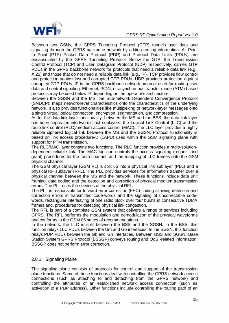
Between two GSNs, the GPRS Tunneling Protocol (GTP) tunnels user data andsignaling through the GPRS backbone network by adding routing information. All Pointto Point (PTP) Packet Data Protocol (PDP) and Protocol Data Units (PDUs) areencapsulated by the GPRS Tunneling Protocol. Below the GTP, the TransmissionControl Protocol (TCP) and User Datagram Protocol (UDP) respectively, carries GTPPDUs in the GPRS backbone network for protocols that need a reliable data link (e.g.,X.25) and those that do not need a reliable data link (e.g., IP). TCP provides flow controland protection against lost and corrupted GTP PDUs. UDP provides protection againstcorrupted GTP PDUs. IP is the GPRS backbone network protocol used for routing userdata and control signaling. Ethernet, ISDN, or asynchronous transfer mode (ATM) basedprotocols may be used below IP depending on the operator's architecture.Between the SGSN and the MS, the Sub-network Dependent Convergence Protocol(SNDCP): maps network-level characteristics onto the characteristics of the underlyingnetwork. It also provides functionalities like multiplexing of network-layer messages ontoa single virtual logical connection, encryption, segmentation, and compression.As for the data link layer functionality, between the MS and the BSS, the data link layerhas been separated into two distinct sublayers, the Logical Link Control (LLC) and theradio link control (RLC)/medium access control (MAC). The LLC layer provides a highlyreliable ciphered logical link between the MS and the SGSN. Protocol functionality isbased on link access procedure-D (LAPD) used within the GSM signaling plane withsupport for PTM transmission.The RLC/MAC layer contains two functions. The RLC function provides a radio-solution-dependent reliable link. The MAC function controls the access signaling (request andgrant) procedures for the radio channel, and the mapping of LLC frames onto the GSMphysical channel.The GSM physical layer (GSM PL) is split up into a physical link sublayer (PLL) and aphysical RF sublayer (RFL). The PLL provides services for information transfer over aphysical channel between the MS and the network. These functions include data unitframing, data coding and the detection and correction of physical medium transmissionerrors. The PLL uses the services of the physical RFL.The PLL is responsible for forward error correction (FEC) coding allowing detection andcorrection errors in transmitted code-words and the signaling of uncorrectable code-words, rectangular interleaving of one radio block over four bursts in consecutive TDMAframes and, procedures for detecting physical link congestion.The RFL is part of a complete GSM system that delivers a range of services includingGPRS. The RFL performs the modulation and demodulation of the physical waveformsand conforms to the GSM 05 series of recommendations.In the network, the LLC is split between the BSS and the SGSN. In the BSS, thisfunction relays LLC PDUs between the Um and Gb interfaces. In the SGSN, this functionrelays PDP PDUs between the Gb and Gn interfaces. Between BSS and SGSN, BaseStation System GPRS Protocol (BSSGP) conveys routing and QoS -related information.BSSGP does not perform error correction.
2.8.1 Signaling Plane
The signaling plane consists of protocols for control and support of the transmissionplane functions. Some of these functions deal with controlling the GPRS network accessconnections (such as attaching to and detaching from the GPRS network) andcontrolling the attributes of an established network access connection (such asactivation of a PDP address). Other functions include controlling the routing path of an

GPRS RF Optimization Report ver 1.0
© Copyright 2000 Wireless Facilities, Inc. - EMEA Confidential- Internal Use Only16
established network connection in order to support user mobility; and controlling theassignment of network resources to meet changing user demands; and providingsupplementary services.Fig. 3 shows the signaling plane between MS and SGSN. GPRS Mobility Managementand Session Management (GMM/SM) is a protocol that supports mobility managementfunctionality such as GPRS attach, GPRS detach, security, routing area update, locationupdate, PDP context activation, and PDP context deactivation.
Ms Um BSS Gb SGSN
Fig.3: Signaling plane MS-SGSN
2.9 The Air Interface
The air interface design of GSM-GPRS allows a GPRS MS to access and obtain servicefrom a GPRS-network. The air interface protocol is concerned with communicationsbetween MS and BSS at the physical, MAC, and RLC protocol layers. The RLC/MACsublayer allows efficient multi-user multiplexing on the shared packet data channel(s)(PDCH) and utilizes a selective ARQ protocol for reliable transmissions across the airinterface.
2.9.1 Physical Layer
The physical channel dedicated to packet data traffic is called a packet data channel(PDCH). A cell that supports GPRS may allocate one or more shared PDCHs, which aretaken from the common pool of physical channels available to the cell and otherwiseused as traffic channels (TCHs). The allocation of TCHs and PDCHs is done
GMM/SM
BSSGP
Networkservice
GMM/SM
LLC
RLC
MAC
GSM RF
LLC
L1bis
RLC
MAC
GSM RF
BSSGP
NetworkService
L1bis

GPRS RF Optimization Report ver 1.0
© Copyright 2000 Wireless Facilities, Inc. - EMEA Confidential- Internal Use Only17
dynamically according to the "capacity on demand" principle, which is an importantconcept in GPRS air interface other than the Master-slave concept.The master-slave concept states that at least one PDCH (mapped on one physical timeslot), acting as a master, accommodates packet common control channels (PCCCHs)which carry all necessary control signaling for initiating packet transfer as well as userdata and dedicated signaling. The others, acting as slaves, are only used for user datatransfer. The capacity on demand concept states that load supervision should be done inthe MAC layer to monitor the load on the PDCH(s), and the number of allocated PDCHsin a cell can be increased or decreased according to demand. However, the existence ofPDCH(s) does not imply the existence of PCCCH. When no PCCCH is allocated in acell, all GPRS attached MSs automatically camp on the existing GSM CCCH as they doin the idle state. When a PCCCH is allocated in a cell, all GPRS attached MS camp on it.
Group Name Direction Function DescriptionPBCCH PBCCH Downlink Broadcast Transmits system information to all GPRS
terminals in a cell.PRACH Uplink Random
accessUsed by the MSs to initiate packet transfers orrespond to paging messages on this chanel.MSstransmit access burst with long guard times.Onreceiving access bursts the BSS assigns a timingadvance to each terminal.
PPCH Downlink Paging Used to page an MS prior to downlink packettransfer
PAGCH Downlink Accessgrant
Used in the packet transfer establishment phaseto send resource assignment to an MS prior tothe packet transfer.
PCCCH
PNCH Downlink Multicast Used to send a PTM Multicast notification to agroup of MSs prior to a PTM packet transfer.Thenotification hasthe form of a resource assignmentfor the packet transfer.
PDTCH Downlinkand Uplink
Data It’s used for data transfer.More than one PDTCHcan be used in parallel(Multislot operation) forindividual.
PTCH
PACCH Downlinkand Uplink
Associatedcontrol
It’s used to convey signalling Information relatedto agiven Ms such asacknowledgements (Ack)and power control (PC) information.It also carriesresource assignment messages either forallocation of a PDTCH or further occurences of aPACCH,one PACCH is associated with one orseveral PDTCHs concurrently assigned to oneMS.
Table 1: GPRS Logical Channels
In GPRS, a multiframe structure is needed for the PDCH in order to accommodatepaging groups and possibly blocks for broadcasting GPRS system information. The

GPRS RF Optimization Report ver 1.0
© Copyright 2000 Wireless Facilities, Inc. - EMEA Confidential- Internal Use Only18
multiframe structure of both 51 TDMA frames and 52 TDMA frames are the same asthose specified for GSM.The network layer protocol data units (N-PDUs or packets) received form the networklayer are transmitted across the air interface between the MS and the SGSN using theLLC protocol. First, the SNDCP transforms packets into LLC frames. The processincludes optional header/data compression, segmentation, and encryption. An LLCframe is then segmented into RLC data blocks, which are formatted into the physicallayer. Each block comprises four normal bursts in consecutive TDMA frames. Table 2lists the GPRS logical channels and their functions. Fig. 4 shows the packettransformation data flow.
Packet(N-PDU) Network Layer
LLC Frame SNDCP Layer
LLC Layer
RLC Block RLC/MAC Layer
Normal burst
Physical Layer
PH: Packet headerFH: Frame headerBH: Block headerFCS: Frame check sequenceBSC: Block check sequence
Fig. 4: Packet transformation data flow
Four different coding schemes, CS-1 to CS-4, are defined for the radio blocks carryingRLC data blocks. In GPRS, the differential initial code rates are obtained by puncturing adifferent number of bits from a common convolution code (rate 1/3). The resulting codingschemes are listed in Table 2. The selection of the initial modulation and code rate touse is based on regular measurements of the link quality.
PH User data
Segment Segment
FH Info FSC
Segme Segme Segme
BH Info BS Trail
Convolutional encoding
Burst Burst Burst Burst

GPRS RF Optimization Report ver 1.0
© Copyright 2000 Wireless Facilities, Inc. - EMEA Confidential- Internal Use Only19
Table 2 - Coding parameters for the GPRS coding schemes
2.9.2 Medium Access Control
The MAC sublayer manages access to the physical layer resources to minimizecollisions between multiple users and to efficiently use the RF resources. The MACsublayer serves as a shared medium between multiple MSs and the BSs for the transferof higher layer service data units (SDUs).
2.9.3 Radio Resource Management
GPRS radio resource management procedures are required for the following functions:− allocation and release of physical resources (i.e., timeslots) associated with a
GPRS channel;− monitoring GPRS channel utilization to detect under-utilized or congested GPRS
channels;− initiating congestion control procedures; and− distribution of GPRS channel configuration information for broadcasting to the
MSs.
GSM radio resources are dynamically shared between GPRS and other GSM services.GPRS radio resources may dynamically be increased to an operator defined maximumor decrease to an operator defined minimum.
2.9.4 Mobility Management
The mobility management functions of GPRS ensure that the network knows the currentlocation of MSs and provides user identity confidentiality. This is done by informationexchange between the SGSN and the MSC/VLR.Among other functions, mobility management deals with cell selection, attach, routingarea, update, detach and suspend procedures. These functions are based on thedefinition of the possible states and MS and a SGSN can have (i.e., idle, steady andready). Mobility management functions are performed taking into account the mobileclass.
Channel name Radio Interface rate per timeslot(kbps)
CS-1CS-2CS-3CS-4
9.0513.415.621.4

GPRS RF Optimization Report ver 1.0
© Copyright 2000 Wireless Facilities, Inc. - EMEA Confidential- Internal Use Only20
2.10 GPRS Operation
In order to access the GPRS services, an MS shall first make its presence known to thenetwork by performing a GPRS attach. This operation establishes a logical link betweenthe MS and the SGSN, and makes the MS available for SMS over GPRS, paging viaSGSN, and notification of incoming GPRS data.In order to send and receive GPRS data, the MS shall activate the packet data addressthat it wants to use. This operation makes the MS known in the corresponding GGSN,and interworking with external data networks can commence.User data is transferred transparently between the MS and the external data networkswith a method known as encapsulation and tunneling: data packets are equipped withGPRS-specific protocol information and transferred between the MS and GGSN. Thistransparent transfer method lessens the requirement for the GPRS PLMN to interpretexternal data protocols, and it enables easy introduction of additional interworkingprotocols in the future. User data can be compressed and protected with retransmissionprotocols for efficiency and reliability.
Fig. 5 - An example of routing
Fig. 5 shows a simple example of routing in a mobile originated transmission. Theserving SGSN of the source mobile encapsulates the packets transmitted by the MS androutes them to the appropriate GGSN. Based on the examination of the destinationaddress, packets are then routed on the destination GGSN through the packet datanetwork. The GGSN checks the routing context associated with the destination addressand determines the serving SGSN and relevant tunneling information. Each packet is

GPRS RF Optimization Report ver 1.0
© Copyright 2000 Wireless Facilities, Inc. - EMEA Confidential- Internal Use Only21
then encapsulated and forwarded to the SGSN, which delivers it to the destinationmobile.
2.10.1 Mobile Originated Packet Transfer
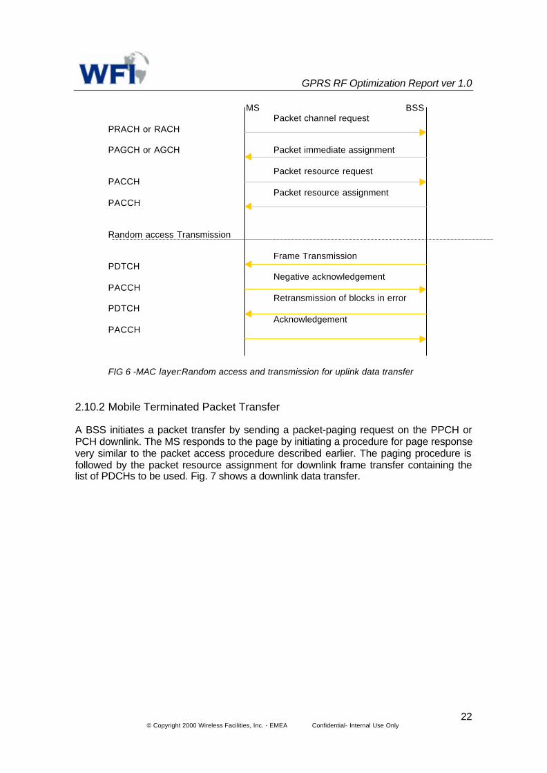
An MS initiates a packet transfer by making a packet channel request on the PRACH orRACH. The network responds on PAGCH or AGCH, respectively. Fig. 6 shows an up-link data transfer procedure. It is possible to use a one -or two phase- packet accessmethod. In one phase access, the network responds to the packet channel request withthe packet immediate assignment, reserving the resources on the PDCHs for up-linktransfer of radio blocks. In a two-phase access, the network responds to the packetchannel request with the packet immediate assignment, which reserves the up-linkresources for transmitting the packet resource request. The packet resource requestcarries the complete description of the requested resources for the up-link transfer.Thereafter, the network responds with the packet resource assignment, reservingresources for the up-link transfer.
If there is no response to the packet channel request within a predefined time period, theMS retries after a random back-off time. However, the MS may contend again eventhough its last packet channel request was already correctly received. This couldproduce a wave of packet channel request on the BSS that may exceed the limit ofpackets that it can handle. To avoid this problem, the sender is notified that its messageis correctly received and that it will receive a resource assignment later. In this way, thesystem builds a queue of MSs, which wait for their turn to receive a packet resourceassignment to send a frame.On a request for an attach, authentication of the MS may be performed (i.e. the SGSNobtains triplet information and challenges the MS). If the MS passes authentication,GSM encryption is used and subscriber data from the GPRS HLR is downloaded into theSGSN. In order to access a data service, the user is first required to establish a PDPcontext with the network. This identifies to the network the type of data network to whichthe mobile station wishes to connect (e.g., X.25 or IP) and, in the case of IP, if a static ordynamic IP address is to be used. The IP address space may belong to either a GSMservice provider or another data network. In addition, the context identifies the point ofinterconnect to the data network (the GGSN). In the case of dynamic IP allocation, theGGSN or network behind the GGSN allocates the IP address.
GPRS RF Optimization Report ver 1.0
© Copyright 2000 Wireless Facilities, Inc. - EMEA Confidential- Internal Use Only22
MS BSS Packet channel request
PRACH or RACH
PAGCH or AGCH Packet immediate assignment
Packet resource requestPACCH
Packet resource assignmentPACCH
Random access Transmission
Frame TransmissionPDTCH
Negative acknowledgementPACCH
Retransmission of blocks in errorPDTCH
AcknowledgementPACCH
FIG 6 -MAC layer:Random access and transmission for uplink data transfer
2.10.2 Mobile Terminated Packet Transfer
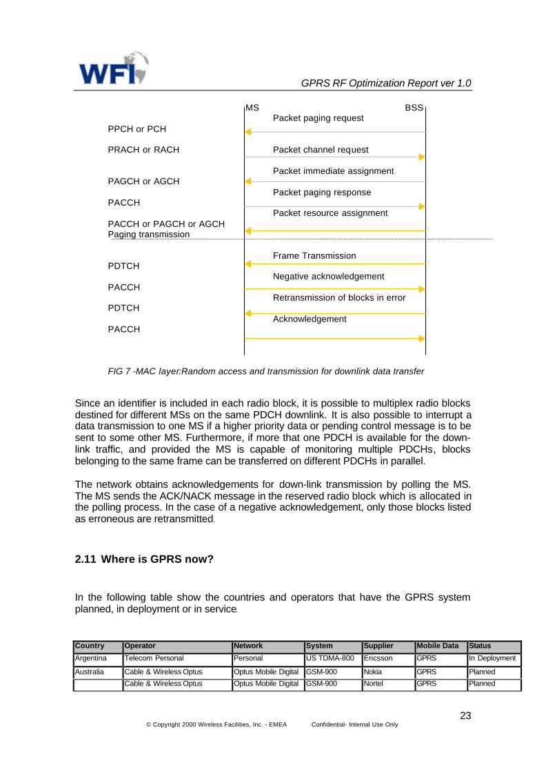
A BSS initiates a packet transfer by sending a packet-paging request on the PPCH orPCH downlink. The MS responds to the page by initiating a procedure for page responsevery similar to the packet access procedure described earlier. The paging procedure isfollowed by the packet resource assignment for downlink frame transfer containing thelist of PDCHs to be used. Fig. 7 shows a downlink data transfer.
GPRS RF Optimization Report ver 1.0
© Copyright 2000 Wireless Facilities, Inc. - EMEA Confidential- Internal Use Only23
MS BSS Packet paging request
PPCH or PCH
PRACH or RACH Packet channel request
Packet immediate assignmentPAGCH or AGCH
Packet paging responsePACCH
Packet resource assignmentPACCH or PAGCH or AGCHPaging transmission
Frame TransmissionPDTCH
Negative acknowledgementPACCH
Retransmission of blocks in errorPDTCH
AcknowledgementPACCH
FIG 7 -MAC layer:Random access and transmission for downlink data transfer
Since an identifier is included in each radio block, it is possible to multiplex radio blocksdestined for different MSs on the same PDCH downlink. It is also possible to interrupt adata transmission to one MS if a higher priority data or pending control message is to besent to some other MS. Furthermore, if more that one PDCH is available for the down-link traffic, and provided the MS is capable of monitoring multiple PDCHs, blocksbelonging to the same frame can be transferred on different PDCHs in parallel.
The network obtains acknowledgements for down-link transmission by polling the MS.The MS sends the ACK/NACK message in the reserved radio block which is allocated inthe polling process. In the case of a negative acknowledgement, only those blocks listedas erroneous are retransmitted.
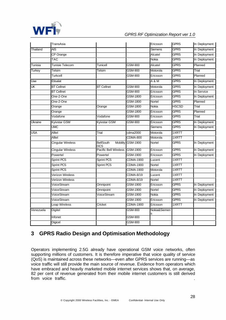
2.11 Where is GPRS now?
In the following table show the countries and operators that have the GPRS systemplanned, in deployment or in service.
Country Operator Network System Supplier Mobile Data Status
Argentina Telecom Personal Personal US TDMA-800 Ericsson GPRS In Deployment
Australia Cable & Wireless Optus Optus Mobile Digital GSM-900 Nokia GPRS PlannedCable & Wireless Optus Optus Mobile Digital GSM-900 Nortel GPRS Planned

GPRS RF Optimization Report ver 1.0
© Copyright 2000 Wireless Facilities, Inc. - EMEA Confidential- Internal Use Only24
Telstra CDMA-800 Nortel 1XRTTVodafone Vodafone GSM-900 Ericsson GPRS Planned
Austria Connect Austria One GSM-1800 Nokia HSCSD Plannedmax.mobil Siemens GPRS In ServiceMobilkom A1 - Mobilkom GSM-9/18 Motorola GPRS Plannedtele.ring GSM-1800 Alcatel GPRS In Service
Belgium Belgacom Mobile Proximus GSM-900 Motorola GPRS PlannedBelgacom Mobile Proximus GSM-9/18 Motorola GPRS PlannedMobistar GSM-900 Nokia GPRS Trial
Bolivia Entel Movil Entel Movil GSM-1900 Ericsson GPRS In DeploymentNuevatel Nuevatel GSM-1900 Nokia GPRS In DeploymentTelemar Alcatel&Nokia GPRS In Deployment
Brazil MobiTel Siemens GPRS In Service
Bulgaria GloBul Motorola GPRS In Deployment
Canada Clearnet Communications PCS CDMA-1900 Lucent 1XRTTMicrocell Telecommunications Fido CDMA-1900 Ericsson GPRS In DeploymentMicrocell Telecommunications Fido CDMA-1900 Nortel GPRS In DeploymentRogers AT&T Cantel AT&T US TDMA-8/19 Ericsson GPRS In DeploymentBell Mobility CDMA-1900 Nortel 1XRTTBell Mobility CDMA-1900 Nortel 1XRTT
China Beijing Mobile GSM-900 Motorola GPRS In DeploymentBeijing Unicom GSM-900 Siemens GPRS TrialChina Mobile A, M, N & E GPRS TestChina Unicom No, M & S GPRS TestChongqing Mobile CTA GSM-900 Ericsson GPRS In DeploymentFujian Mobile GSM-900 Nokia GPRS In DeploymentFujian Mobile GSM-9/18 Nokia GPRS PlannedFuzhou Unicom GSM-900 Siemens GPRS TrialGuangdong Mobile GSM-900 Ericsson GPRS In DeploymentGuangdong Mobile GSM-900 Nokia GPRS In DeploymentShenzhen Unicom GSM-900 Motorola GPRS In DeploymentGuangxi Mobile GSM-900 Ericsson GPRS In DeploymentHainan Mobile GSM-900 Nokia GPRS In DeploymentHebei Mobile GSM-900 Ericsson GPRS In DeploymentHebei Mobile GSM-900 Motorola GPRS PlannedHebei Mobile GSM-900 Nortel GPRS TrialHeilongjiang Unicom GSM-900 Siemens GPRS In DeploymentHenan Mobile GSM-900 Nokia GPRS PlannedHubei Mobile GSM-900 Ericsson GPRS In DeploymentJiangsu Mobile GSM-900 Ericsson GPRS In DeploymentNanjing Unicom GSM-900 Alcatel GPRS TrialWuxi Unicom GSM-900 Ericsson GPRS TrialShandong Mobile GSM-900 Ericsson GPRS In DeploymentShanghai Mobile GSM-1800 Ericsson GPRS In DeploymentShanghai Mobile GSM-900 Siemens GPRS TrialShanghai Unicom GSM-900 Nokia GPRS PlannedShanghai Unicom GSM-900 Siemens GPRS PlannedSichuan Mobile GSM-900 Motorola GPRS In Deployment

GPRS RF Optimization Report ver 1.0
© Copyright 2000 Wireless Facilities, Inc. - EMEA Confidential- Internal Use Only25
Tianjin Mobile GSM-900 Motorola GPRS In DeploymentTianjin Mobile GSM-900 Nortel GPRS TrialYunnan PTA GSM-900 Nokia HSCSD In DeploymentZhejiang Mobile GSM-900 Alcatel GPRS TrialZhejiang Mobile GSM-900 Motorola GPRS In DeploymentZhejiang Unicom GSM-900 Nortel GPRS PlannedCroNet Siemens GPRS In Service
Croatia Vip Net Ericsson GPRS In Service
Cyprus CYTA (South) Ericsson GPRS In Deployment
Czech Cesky Mobil Oscar GSM-9/18 Ericsson GPRS PlannedRepublic EuroTel Praha Nokia GPRS In Deployment
RadioMobil Paegas GSM-900 Motorola GPRS In Deployment
Denmark Dansk Mobil Telefon Sonofon GSM-900 Nokia GPRS TrialMobilix Mobilix GSM-1800 Nokia GPRS TrialOrange Nokia GPRS In DeploymentTele Danmark Mobil GSM-1800 Nokia HSCSD In ServiceTelia Ericsson GPRS In ServiceTele Danmark Mobil GSM-900 Nokia HSCSD In Service
El Salvador Personal Alcatel GPRS In Deployment
Estonia Radiolinja Nokia GPRS In Deployment
Finland Alands Mobile Ericsson GPRS In DeploymentRadiolinja GSM-900 Nokia GPRS In DeploymentRadiolinja GSM-900 Siemens GPRS TrialRadiolinja GSM-9/18 Nokia GPRS In DeploymentRadiolinja GSM-9/18 Siemens GPRS TrialSonera GSM-900 Ericsson GPRS In ServiceSonera GSM-9/18 Nokia HSCSD In ServiceSuomen 2G Ericsson GPRS In DeploymentTelia Nokia GPRS In Deployment
France Bouygues Telecom Bouygues GSM-1800 Nortel GPRS TrialCegetel SFR GSM-900 Alcatel GPRS TrialCegetel SFR GSM-900 Nokia GPRS PlannedFrance Telecom Itineris GSM-900 Alcatel GPRS TrialFrance Telecom Itineris GSM-900 Motorola GPRS TrialFrance Telecom Itineris GSM-9/18 Alcatel GPRS TrialFrance Telecom Itineris GSM-9/18 Motorola GPRS TrialOrange France Alcatel GPRS In Deployment
Germany E-Plus Nokia GPRS In ServiceMannesmann Mobilfunk D2 GSM-900 Ericsson HSCSD In ServiceMannesmann Mobilfunk D2 GSM-900 Siemens GPRS PlannedT-Mobil D1 GSM-900 Alcatel GPRS In DeploymentT-Mobil D1 GSM-900 Ericsson GPRS In DeploymentT-Mobil D1 GSM-900 Lucent GPRS In DeploymentT-Mobil D1 GSM-900 Motorola GPRS In ServiceViag Interkom E2 Mobilfunk GSM-1800 Nokia GPRS In Service
Greece Cosmote Cosmote GSM-1800 Nokia GPRS In ServicePanafon Panafon GSM-900 Ericsson GPRS In Service
Hong Kong Cable & Wireless HKT 1010 and One2Free GSM-9/18 Nokia HSCSD Planned

GPRS RF Optimization Report ver 1.0
© Copyright 2000 Wireless Facilities, Inc. - EMEA Confidential- Internal Use Only26
Mandarin Communications Sunday GSM-1800 Nortel GPRS TrialNew World Telephone New World PCS GSM-1800 Nokia HSCSD In DeploymentNew World Telephone New World PCS GSM-1800 Nokia HSCSD In DeploymentPacific Century CyberWorksHKT
1010 and One2Free GSM-9/18 Nokia HSCSD Planned
Peoples Phone Ericsson GPRS In DeploymentSmarTone SmarTone GSM-900 Ericsson GPRS In DeploymentSmarTone SmarTone GSM-9/18 Ericsson GPRS In DeploymentSmarTone GSM-900 Ericsson GPRS In DeploymentSunday Communications GSM-1800 Nortel GPRS TrialPannon Ericsson GPRS In Service
Hungary Westel 900 Eurofon GSM-900 Motorola GPRS Trial
Iceland Landssimi Ericsson GPRS In DeploymentTAL TAL GSM-900 Nortel GPRS Planned
India BPL Mobile GSM-900 Motorola GPRS PlannedEscotel Mobile-Haryana Lucent GPRS In DeploymentEscotel Mobile-Kerala Lucent GPRS In DeploymentEscotel Mobile-Uttar Pradesh Lucent GPRS In DeploymentSpice Communications-Punjab GPRS Planned
Indonesia Telkomsel Siemens GPRS In Deployment
Ireland Eircell Ericsson GPRS In ServiceEsat Digifone Nortel GPRS In Deployment
Israel Orange Ericsson GPRS In Service
Italy Blu GSM-1800 Nokia GPRS PlannedOmnitel Nokia GPRS In ServiceTelecom Italia Mobile GSM-900 Ericsson HSCSD In DeploymentTelecom Italia Mobile GSM-900 Siemens GPRS TrialTelecom Italia Mobile GSM-9/18 Ericsson HSCSD In Deployment
Lebanon FTML Cellis GSM-900 Ericsson GPRS Planned
Liechtenstein Viag Europlattform GSM-1800 Nokia GPRS In DeploymentBite Ericsson GPRS In Deployment
Lithuania Omnitel Motorola GPRS In Deployment
Luxembourg LuxGSM Siemens GPRS In ServiceSociété Européenne deCommunication
TANGO GSM-9/18 Ericsson HSCSD In Service
Celcom Celcom GSM GSM-900 Ericsson GPRS PlannedCelcom Cellcom GSM GSM-900 Lucent GPRS Trial
Malaysia Digi Ericsson GPRS In DeploymentTime Wireless Adam GSM-1800 Nokia GPRS In Service
Malta MobIsle Communications GSM-1800 Nortel GPRS PlannedVodafone Siemens GPRS In Service
Mexico Telcel Telcel US TDMA 1900 Ericsson GPRS In Deployment
Morocco ONPT Siemens GPRS In Deployment
Netherlands Ben Nederland Ben GSM-1800 Nokia GPRS PlannedDutchtone Nokia GPRS In DeploymentKPN ATF-4 GSM-900 Ericsson GPRS TrialLibertel Vodafone Ericsson GPRS In ServiceTelfort GSM-1800 Ericsson GPRS In Deployment

GPRS RF Optimization Report ver 1.0
© Copyright 2000 Wireless Facilities, Inc. - EMEA Confidential- Internal Use Only27
New Zealand Vodafone New Zealand (formerly BellSouth) GSM-900 Nokia GPRS Trial
Norway NetCom NetCom GSM-900 Siemens GPRS In ServiceTelenor Mobil Telenor Mobil GSM-900 Ericsson HSCSD In DeploymentTelenor Mobil Telenor Mobil GSM-900 Nokia HSCSD In DeploymentTelenor Mobil Telenor Mobil GSM-9/18 Nokia HSCSD In Deployment
Philippines Globe Telecom Handyphone GSM-900 Nokia GPRS PlannedSmart Communications Gold GSM GSM-9/18 Nokia GPRS Planned
Poland Centertel Idea GSM-1800 Nokia GPRS In ServicePolkomtel Plus GSM GSM-900 Nokia GPRS PlannedPolska Telefonia Cyfrowa Era GSM GSM-9/18 Ericsson GPRS Trial
Portugal Optimus Nokia GPRS In DeploymentTelecel Telecel GSM-900 Ericsson GPRS TrialTelecel Telecel GSM-9/18 Ericsson GPRS In DeploymentTMN Telemovel GSM-9/18 Alcatel GPRS Trial
Qatar Q-Tel Alcatel GPRS In Deployment
Romania MobilRom Siemens GPRS In Service
Russia KB Impuls Bee Line GSM GSM-9/18 Nokia GPRS In DeploymentMobile Telesystems MTS GSM-900 Motorola GPRS In DeploymentSonic Duo Ericsson GPRS In Deployment
Saudi Arabia STC Al-Jawwal GSM GSM-9/18 Lucent GPRS Trial
Singapore MobileOne GSM M1 GSM GSM-900 Nokia HSCSD In ServiceSingapore Telecom SingTel Mobile GSM-900 Ericsson HSCSD In DeploymentSingapore Telecom SingTel Mobile GSM-9/18 Ericsson HSCSD In DeploymentStarHub GSM-1800 Nokia GPRS Trial
South Africa Vodacom Vodacom GSM-900 Alcatel GPRS TrialVodacom Vodacom GSM-900 Siemens GPRS Trial
Spain AirTel S & E GPRS In DeploymentAmena GPRS In ServiceTelefónica MoviStar GSM-9/18 Nokia GPRS In Service
Sweden Convig Siemens GPRS In DeploymentEuropolitan Europolitan GSM-900 Nokia GPRS PlannedEuropolitan GSM-1800 Nokia HSCSD In ServiceTele2 Siemens GPRS In ServiceTelia Mobitel Telia Mobitel GSM GSM-900 Ericsson HSCSD Trial
Switzerland diAx GSM-9/18 Nokia GPRS PlannedOrange GSM-1800 Nokia GPRS PlannedSunrise Nokia GPRS In DeploymentSwisscom GSM-9/18 Ericsson GPRS In Deployment
Taiwan Chunghwa Telecom GSM National GSM-9/18 Nokia GPRS PlannedChunghwa Telecom GSM National GSM-9/18 Nortel GPRS PlannedFarEasTone GSM-1800 GSM-9/18 Ericsson GPRS TrialMobitai Siemens GPRS In DeploymentKG Telecom GSM-1800 GSM-1800 Nokia GPRS In DeploymentFarEasTone GSM North GSM-900 Ericsson GPRS TrialKG Telecom GSM-1800 GSM-1800 Lucent GPRS PlannedKG Telecom GSM-1800 GSM-1800 Nokia GPRS In ServiceKG Telecom GSM-1800 GSM-1800 Nokia GPRS In Deployment
GPRS RF Optimization Report ver 1.0
© Copyright 2000 Wireless Facilities, Inc. - EMEA Confidential- Internal Use Only28
TransAsia Ericsson GPRS In Deployment
Thailand AIS Siemens GPRS In DeploymentCP Orange Alcatel GPRS In DeploymentTAC Nokia GPRS In Deployment
Tunisia Tunisie Telecom Tunicell GSM-900 Alcatel GPRS Planned
Turkey Telsim Telsim GSM-900 Motorola GPRS TrialTurkcell GSM-900 Ericsson GPRS Planned
Uae Etisalat A & M GPRS In Deployment
UK BT Cellnet BT Cellnet GSM-900 Motorola GPRS In DeploymentBT Cellnet GSM-900 Ericsson GPRS In ServiceOne-2-One GSM-1800 Ericsson GPRS In DeploymentOne-2-One GSM-1800 Nortel GPRS PlannedOrange Orange GSM-1800 Nokia HSCSD TrialOrange GSM-1800 Ericsson GPRS PlannedVodafone Vodafone GSM-900 Ericsson GPRS Trial
Ukraine Kyivstar GSM Kyivstar GSM GSM-900 Ericsson GPRS In DeploymentUMC Siemens GPRS In Deployment
USA Alltel Trial cdma2000 Motorola 1XRTTAlltel CDMA-800 Motorola 1XRTTCingular Wireless BellSouth Mobility
DCSGSM-1900 Nortel GPRS In Deployment
Cingular Wireless Pacific Bell Wireless GSM-1900 Ericsson GPRS In DeploymentPowertel Powertel GSM-1900 Ericsson GPRS In DeploymentSprint PCS Sprint PCS CDMA-1900 Lucent 1XRTTSprint PCS Sprint PCS CDMA-1900 Nortel 1XRTTSprint PCS CDMA-1900 Motorola 1XRTTVerizon Wireless CDMA-8/19 Lucent 1XRTTVerizon Wireless CDMA-8/19 Nortel 1XRTTVoiceStream Omnipoint GSM-1900 Ericsson GPRS In DeploymentVoiceStream Omnipoint GSM-1900 Nortel GPRS In DeploymentVoiceStream VoiceStream GSM-1900 Nokia GPRS In DeploymentVoiceStream GSM-1900 Ericsson GPRS In DeploymentLeap Wireless Cricket CDMA-1900 Ericsson 1XRTT
Venezuela Digitel GSM-900 Nokia&Siemens
Infonet GSM-900Digicel GSM-900
3 GPRS Radio Design and Optimisation Methodology
Operators implementing 2.5G already have operational GSM voice networks, oftensupporting millions of customers. It is therefore imperative that voice quality of service(QoS) is maintained across these networks—even after GPRS services are running—asvoice traffic will still provide the main source of revenue. Evidence from operators whichhave embraced and heavily marketed mobile internet services shows that, on average,82 per cent of revenue generated from their mobile internet customers is still derivedfrom voice traffic. .
GPRS RF Optimization Report ver 1.0
© Copyright 2000 Wireless Facilities, Inc. - EMEA Confidential- Internal Use Only29
Currently, some of the largest GSM networks have over 60 per cent of their customerbase using prepaid services. While the growth of prepaid services has greatly enhancedoperators' customer bases and revenues, it has also driven the requirements for fullyoptimised radio interfaces, as the increased demand has required more efficientfrequency reuse, traffic management algorithms and aggressive parametermanagement.
3.1 Visibility of network performance
The importance of an optimised air interface, one that will deliver 2.5G services throughthe same scarce air interface resource effectively, increases as the network customerbase grows—and particularly when that growth is rapid. In order for operators to meetthis increased challenge through optimisation techniques, the need for clear and relevantvisibility of network performance becomes critical. The reuse of the same radio interfacein 2.5G networks means that visibility of interactions between the circuit and packet-switched traffic in radio resource usage is imperative for capacity planning, trafficmanagement algorithm development, hot-spot detection and engineering rule designand validation.
One of the major factors driving this search for detail is the significant differences in howand where control of the interaction between the mobile terminal and the networkresides in 2G and 2.5G networks. In 2.5G, the network will no longer enjoy the levels ofcontrol that it currently has in 2G and this will directly affect optimisation strategies.
Providing an optimised 2G network requires a detailed understanding of how thenetwork is operating. This understanding is gained through a mixture of OSS systems,drive tests, comparative / benchmarking exercises, detailed investigation and, of course,customer feedback.
2G operators have access to measurement systems that have matured with thenetworks, providing a rich variety of views on network performance. These tools enableboth network monitoring and localised investigation to be available to optimisationteams. Although there are limitations in each individual tool, used together, the operatorcan access a wealth of data and accumulated knowledge.
The 2.5G networks, which have recently been launched or are very soon to be launched,lack the support of mature measurement systems and the ubiquitously available toolsfrom the 2G environment. In fact, until relatively recently, the extent of the problem wassuch that reliable terminals with which network testing could begin were not evenavailable.
3.2 Unknown service requirements
Although the introduction of test mobiles has been addressed and measurementsystems are beginning to deliver the visibility of network performance operators expectand require, other issues for 2.5G network optimisation have become more pressing. In2G, where voice calls and usage patterns are relatively well understood, the majorproblems faced by the operator were the volumes of data to be captured and analysed.
GPRS RF Optimization Report ver 1.0
© Copyright 2000 Wireless Facilities, Inc. - EMEA Confidential- Internal Use Only30
In 2.5G networks, whilst the existing challenges with voice remain, there are additionalproblems, particularly 'what services will be used by which customers, where, when andin what quantities?’ For example, if we look at the Scandinavian countries where mobilepenetration rates are highest, the impact of having sections of the population with almost100 per cent mobile ownership rates has meant that additional services, such as mobilechat rooms, are being developed and deployed. These were unforeseen at the launch ofGSM. Again, looking at how mobile usage patterns have migrated from the early adoptercountries to the rest of the world, it is fair to assume that what is happening inScandinavia is likely to appear elsewhere as the economic opportunity for servicesdevelop. This leaves the operators with a challenge: how to optimise the 2.5G networkswithout impacting their growing 2G networks and without fully understanding how thesenetworks will be used? However, the rate at which the new 2.5G networks will be used islargely in the hands of the network operators. They can control the rate of uptakesthrough their policies on handset availability, service offering, pricing structures,partnerships and co-operation with branded and proven content providers. Operators arealready aware of the impact of these policies through their 2G experience and thepolicies through their 2G experience and the effects of the prepaid explosion on theirnetworks.
In order to optimise these 2.5G networks, operators now require tools that can be usedto understand, in detail, how the packet network service usage is interacting with theirvoice services. These tools must provide the ability to analyse and report on networkperformance based on multiple manufacturer test handset types, because as with 2G,terminal performance directly impacts the customers' perception of service. The detailsof call/session events and the sequences of these events, as seen from the often multi-vendor network infrastructure, must therefore be clearly visible and accessible throughany new optimisation tools.
Any new tools must also permit operators to develop algorithms in their network-levelmeasurement tools for wholesale network optimisation— algorithms that will requirerefining and developing as the handset and service mix on the 2.5G networks alter andas the user base grows. The advantages of providing optimised networks, deliveringmaximum QoS and equipment use are well known from experience in 2G.
3.3 Design Cases
This document considers two scenarios where the GPRS design is concern. This caninvolve a new design for a GPRS services and a migration from GSM to GPRS network.
3.3.1 New GSM Network Design with GPRS
In comparison, designing a new 2.5G GSM air interface from scratch (one which wouldcater for internet) is much easier than optimising the existing GSM air interface toaccommodate for GPRS.
In the new design for GPRS all parameters regarding GPRS will be included in the linkbudgets as shown below in the next section. In the new design the cell radius will havebeen already calculated with GPRS in mind. As a result the network will be designed
GPRS RF Optimization Report ver 1.0
© Copyright 2000 Wireless Facilities, Inc. - EMEA Confidential- Internal Use Only31
according to the market requirements to ensure QoS. Further more, the allocation oftime slot to GPRS could also be determined from the start to ensure the requiredthroughput with regards to capacity study.
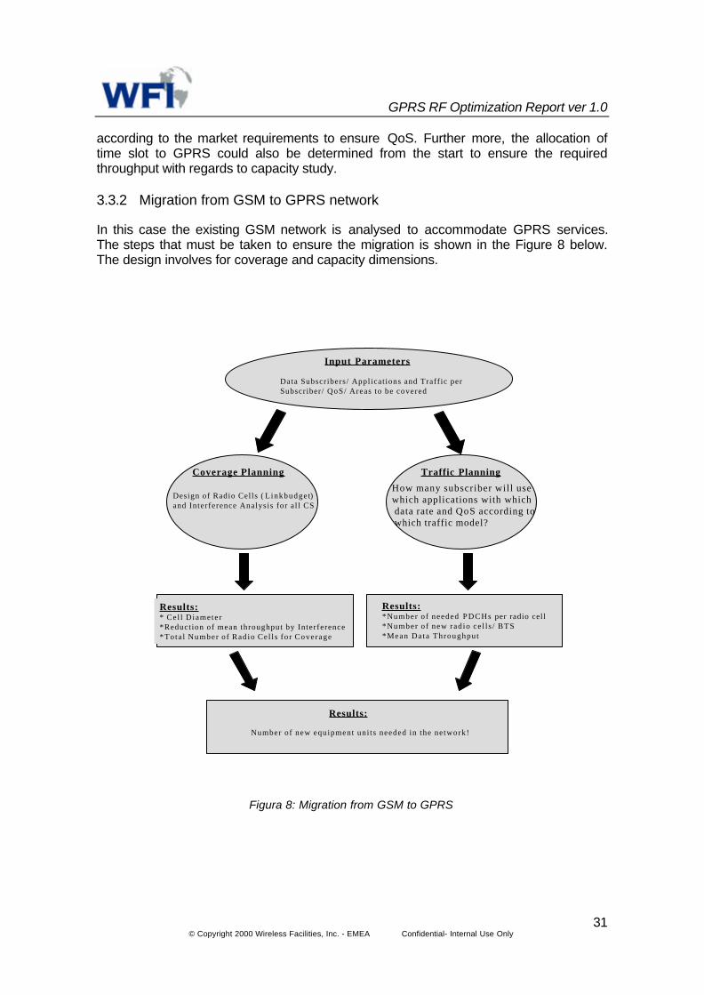
3.3.2 Migration from GSM to GPRS network
In this case the existing GSM network is analysed to accommodate GPRS services.The steps that must be taken to ensure the migration is shown in the Figure 8 below.The design involves for coverage and capacity dimensions.
Input Parameters
Data Subscribers/ Applicat ions and Traffic perSubscriber/ QoS/ Areas to be covered
Coverage Planning
Design of Radio Cells ( L inkbudge t)and Interference Analysis for a l l CS
Traffic Planning
How many subscriber will usewhich applications with which data rate and QoS according to which traffic model?
Results:* Cel l Diameter*Reduct ion of mean throughput by Interference*Tota l Number o f Radio Cel l s fo r Coverage
Results:*Number of needed PDCHs per radio cell*Number o f new rad io ce l l s / BTS*Mean Data Throughput
Results:
Number of new equipment uni ts needed in the network!
Figura 8: Migration from GSM to GPRS

GPRS RF Optimization Report ver 1.0
© Copyright 2000 Wireless Facilities, Inc. - EMEA Confidential- Internal Use Only32
4 GPRS Link Budgets
In analysing the GPRS link budgets, as an example the dense urban area of Paris isconsidered. The design is based on this area. The examples of the link budgets andother parameters are show below.
Inputs to the Link budgets of both GSM and GPRS are shown in the table below.
Table 3: Input data for the GPRS link Budget
Denseurban InDoor Urban InDoor Suburban InDoor Rural-Open InCar Rural-Open OutdoorArea that should be covered (km2) 40 35 1 20 4.2Total Area (km2) 100.2
GeneralInformation Frequency (MHz) 900
Cell pattern Clover pattern Clover pattern Clover pattern Clover pattern Clover patternStandard deviation (dB) 7 7 6 5 5Probability on cell border (%) 90 90 90 90 90BS antenna height (m) 30 30 35 50 50BS Peak Power at PA output (Watt) 35BS Peak Power at PA output (dBm) 45.4BS sensitivity (dBm) -109.4BS sensitivity for CS-1 for GPRS -109.2BS sensitivity for CS-2 for GPRS -105.6
Base BS sensitivity for CS-3 for GPRS -103.4Station BS sensitivity for CS-4 for GPRS -96.1
BS antenna gain (dB) 15.5Uplink diversity gain (dB) 4BS cable loss (dB) 2Connector loss (dB) 0Combiner loss (dB) 5.7Jumper cables loss 0Duplexer loss dB 0MS antenna height (m) 1.5MS Power (Watt) 2
Mobile MS Power (dBm) 33Station MS sensitivity for GSM handsets (dBm) -100
MS sensitivity for GPRS handsets (dBm) -104MS antenna gain (dB) 0Downlink diversity gain (dB) 0Interference degradation margin (dB) 3Inter. Degrad. margin for GPRS load (dB) 2
Other Body loss (dB) 3losses InDoor/InCar penetration loss (dB) 18 18 15 6 0
Fade margin 9 9 7.7 6.4 6.4

GPRS RF Optimization Report ver 1.0
© Copyright 2000 Wireless Facilities, Inc. - EMEA Confidential- Internal Use Only33
Power_Threshold = Mobile_Sensitivity + Losses – MS_Gains
Table 4: Received power thresholds
ERP = Output_Power – Hardware_Losses + BS_Gains
Table 5: Effective Radiated Power
Denseurban InDoor Urban InDoor Suburban InDoor Rural-Open InCar Rural-Open OutdoorPower thresholds (dBm) -67 -67 -71.3 -81.6 -87.6MS sensitivity (dBm) -100 -100 -100 -100 -100
Losses Interference degradation margin (dB) 3 3 3 3 3Body loss (dB) 3 3 3 3 3Fade margin (dB) 9 9 7.7 6.4 6.4InDoor/InCar penetration loss (dB) 18 18 15 6 0
Gains MS antenna gain (dB) 0 0 0 0 0Downlink diversity gain (dB) 0 0 0 0 0
Fade Standard deviation (dB) 7 7 6 5 5margin Probability on cell border (%) 90 90 90 90 90
calculation Fade Margin (dB) 9 9 7.7 6.4 6.4Coding scheme Denseurban InDoor Urban InDoor Suburban InDoor Rural-Open InCar Rural-Open Outdoor
Coding scheme-1 (dBm) -71.8 -71.8 -76.1 -86.4 -92.4For GPRS Coding scheme-2 (dBm) -68.1 -68.1 -72.4 -82.7 -88.7
Coding scheme-3 (dBm) -66.4 -66.4 -70.7 -81 -87Coding scheme-4 (dBm) -58.7 -58.7 -63 -73.3 -79.3
ERP (dBm) 53.2EIRP (dBm) 55.4BS Peak Power at PA output (dBm) 45.4DL-Cable Loss (dB) 2Connector loss (dB) 0Combiner loss (dB) 5.7Duplexer loss (dB) 0Jumper cables loss (dB) 0BS downlink diversity gain (dB) 0BS antenna gain (dB) 15.5
Hardware losses
Gains

GPRS RF Optimization Report ver 1.0
© Copyright 2000 Wireless Facilities, Inc. - EMEA Confidential- Internal Use Only34
4.1 Maximum Allowable Path Loss
Table 6: Maximum allowable path losses for uplink and for downlink
MAPL Up = PA m - L CCC - L Body - L Bldg - M Fade + G B + G M + Diversity gain - RX BaseUplink Denseurban InDoor Urban InDoor Suburban InDoor Rural-Open InCar Rural-Open Outdoor
Max. Allowable Path Loss 126.9 126.9 131.2 141.5 147.5MAPL for GPRS for CS-1 (dB) 129.7 129.7 134 144.3 150.3MAPL for GPRS for CS-2 (dB) 126 126 130.3 140.6 146.6MAPL for GPRS for CS-3 (dB) 124.3 124.3 128.6 138.9 144.9MAPL for GPRS for CS-4 (dB) 116.6 116.6 120.9 131.2 137.2MS Power (dBm) 33BS cable loss (dB) 2Connector loss (dB) 0Jumper cables loss 0Duplexer loss 0Interference degradation margin (dB) 3Body loss (dB) 3InDoor/InCar penetration loss (dB) 18 18 15 6Fade Margin (dB) 9 9 7.7 6.4 6.4MS antenna gain (dB) 0BS antenna gain (dB) 15.5Uplink diversity gain (dB) 4BS sensitivity (dBm) -109.4
PL Down = PA B - L CCC - L Bldg - L Body - M Fade + G M + G B - RX MobileDownlink Denseurban InDoor Urban InDoor Suburban InDoor Rural-Open InCar Rural-Open Outdoor
Max. Allowable Path Loss 120.2 120.2 124.5 134.8 140.8MAPL for GPRS for CS-1 (dB) 125 125 129.3 139.6 145.6MAPL for GPRS for CS-2 (dB) 121.3 121.3 125.6 135.9 141.9MAPL for GPRS for CS-3 (dB) 119.6 119.6 123.9 134.2 140.2MAPL for GPRS for CS-4 (dB) 111.9 111.9 116.2 126.5 132.5BS Power (dBm) 45.4BS cable loss (dB) 2Connector loss (dB) 0Combiner loss (dB) 5.7Jumper cables loss 0Duplexer loss 0Interference degradation margin (dB) 3Body loss (dB) 3InDoor/InCar penetration loss (dB) 18 18 15 6Fade Margin (dB) 9 9 7.7 6.4 6.4MS antenna gain (dB) 0BS antenna gain (dB) 15.5Downlink diversity gain (dB) 0MS sensitivity (dBm) -100

GPRS RF Optimization Report ver 1.0
© Copyright 2000 Wireless Facilities, Inc. - EMEA Confidential- Internal Use Only35
4.2 Cell Size Estimation
Table 7: Cell size estimation
(PathLoss-A+C+A(hm)-Cm )/BPathLoss = A+BlogR-A(hm)-C+Cm R=10
f<1500 A= 69.55+26.16log(f)-13.82log(hb) f = frequency (MHz)1500<f<2000 A= 46.3+33.9log(f)-13.82log(hb) hb = height of the base station antenna (m)
B= 44.9-6.55log(hb)for urban C= 0
for Suburban C= 2[log(f/28)]2+5.4for Open & Rural C= 4.78[log(f)]2-18.33log(f)+40.94
for large cities, A(hm)= [log(11.75hm)]2-4.97 hm = height of the mobile station antenna (m)for other cities, A(hm)= [1.11log(f)-0.7]hm-[1.56log(f)-0.8]
f<1500 Cm= 0f>1500 for large cities Cm= 3f>1500 for other cities Cm= 0
Frequency band A B C [suburban] C [open&rural] A(hm) Cm300< f < 1500MHz 126.4191683 35.22485578 9.942607248 28.50641809 0.060195463 0
1500 > f > 2000MHzDenseurban InDoor Urban InDoor Suburban InDoor Rural-Open InCar Rural-Open Outdoor
Maximum Allowable PathLoss 120.2 120.2 124.5 134.8 140.8MAPL for GPRS for CS-1 (dB) 125.0 125.0 129.3 139.6 145.6MAPL for GPRS for CS-2 (dB) 121.3 121.3 125.6 135.9 141.9MAPL for GPRS for CS-3 (dB) 119.6 119.6 123.9 134.2 140.2MAPL for GPRS for CS-4 (dB) 111.9 111.9 116.2 126.5 132.5A 126.4191683B 35.22485578Clutter correction factor C -1.0 1.0 11.0 29.0 29.0A(hm) 0.060195463Cm 0Range or Radius for GSM (km) 0.626 0.714 1.818 11.559 17.110Radius for CS-1 for GPRS (km) 0.857 0.977 2.488 15.819 23.416Radius for CS-2 for GPRS (km) 0.673 0.767 1.953 12.421 18.386Radius for CS-3 for GPRS (km) 0.602 0.686 1.748 11.114 16.452Radius for CS-4 for GPRS (km) 0.364 0.415 1.057 6.719 9.945

GPRS RF Optimization Report ver 1.0
© Copyright 2000 Wireless Facilities, Inc. - EMEA Confidential- Internal Use Only36
4.3 Cell Count Estimation
Site_Count = ∑(Clutter_Area)/(Site_Area_in_the_Clutter)
Table 8: Cell count estimation
For Clover Pattern: For Hexagon Pattern:R
R
The area of each Cell: The area of each Cell:
The area of each Site: The area of each Site:
C 2
833
_ ×=
RS 2
839
_ ×=
RC 2
23
_ ×=
RS 2
233
_ ×=
Clutter Denseurban InDoor Urban InDoor Suburban InDoor Rural-Open InCar Rural-Open OutdoorClutter area (km2) 40 35 1 20 4.2Cell pattern Clover pattern Clover pattern Clover pattern Clover pattern Clover pattern
Cell range for GSM (km) 0.626 0.714 1.818 11.559 17.11Site size for GSM (km2) 0.764 0.993 6.440 260.348 570.444No of sites in each clutter for GSM 53 36 1 1 1Total no of sites for GSM 92
Required Coding Schemes for GPRS CS-3 CS-3 CS-2 CS-2 CS-2Cell range for required CS for GPRS (km) 0.602 0.686 1.953 12.421 18.386Site size for required CS for GPRS (km2) 0.706 0.917 7.432 300.626 658.700No of sites in each clutter for GPRS 57 39 1 1 1Total no of sites for GPRS 99
Cell Range for GPRS CS-1 (km) 0.857 0.977 2.488 15.819 23.416Cell Range for GPRS CS-2 (km) 0.673 0.767 1.953 12.421 18.386Cell Range for GPRS CS-3 (km) 0.602 0.686 1.748 11.114 16.452Cell Range for GPRS CS-4 (km) 0.364 0.415 1.057 6.719 9.945Site size for GPRS CS-1 (km2) 1.431 1.860 12.062 487.608 1068.412Site size for GPRS CS-2 (km2) 0.883 1.146 7.432 300.626 658.700Site size for GPRS CS-3 (km2) 0.706 0.917 5.954 240.688 527.413Site size for GPRS CS-4 (km2) 0.258 0.336 2.177 87.968 192.718No of sites in each clutter for GPRS CS-1 28 19 1 1 1No of sites in each clutter for GPRS CS-2 46 31 1 1 1No of sites in each clutter for GPRS CS-3 57 39 1 1 1No of sites in each clutter for GPRS CS-4 155 105 1 1 1

GPRS RF Optimization Report ver 1.0
© Copyright 2000 Wireless Facilities, Inc. - EMEA Confidential- Internal Use Only37
5 Considerations in the GPRS link budgets
As we will see in the link budgets there are some new aspects regarding the GPRSdesign that we will have to take into account.
5.1 Rx Sensitivity Vs Coding Scheme
It is known that for a given BLER each type of modulation and coding requires aminimum signal to noise ratio (C/N), which at bit level is stated Eb/No. The Rx sensitivityis depending on this C/N as shown here
Rx= 10 log (KTB) + NF + C/N
To achieve the required BLER (eg 10%) each coding scheme requires a level of C/N,therefore due to the differrent C/N requirements of each coding schemes, the Rxsensitivity will be different for each one of them too. As the data rates increases the errorprotection is reduced and therefore more C/N is required.
As an example here is a table with some results based on simulation of propagationcondition TU50 with ideal frequency hopping and without Rx diversity:
Service QoS RequiredC/N
BS Sensitivity forTalk Family from
NOKIASpeech RBERII<8% 6.0 dB -108 dBmCS-1 BLER<10% 6.2 dB -107.8 dBmCS-2 BLER<10% 9.8 dB -104.1 dBmCS-3 BLER<10% 12 dB -102,0 dBmCS-4 BLER<10% 19.3 dB -94,7 dBm
Table 9: Changes in BTS Sensitivity for differents coding schemes
5.2 Body Loss
The typical 3 dB body loss associated with voice service has to be excluded from theGPRS service link budgets. This gives GPRS services a 3 dB benefit. In effect, thisresult in CS-1 is achieving a higher tolerable path loss than the voice service, while CS-2becomes comparable to the voice service. So the cell radio for CS-1 and CS-2 is usuallybigger or similar than for voice service. Therefore, in terms of coverage, the service forCS-1 and CS-2 will be available at least in the area that would have been covered in aGSM voice network.
The table below shows the parameters that have differences in maximum allowable pathloss in case of sensitivities for various coding schemes and for the GSM voice traffic.
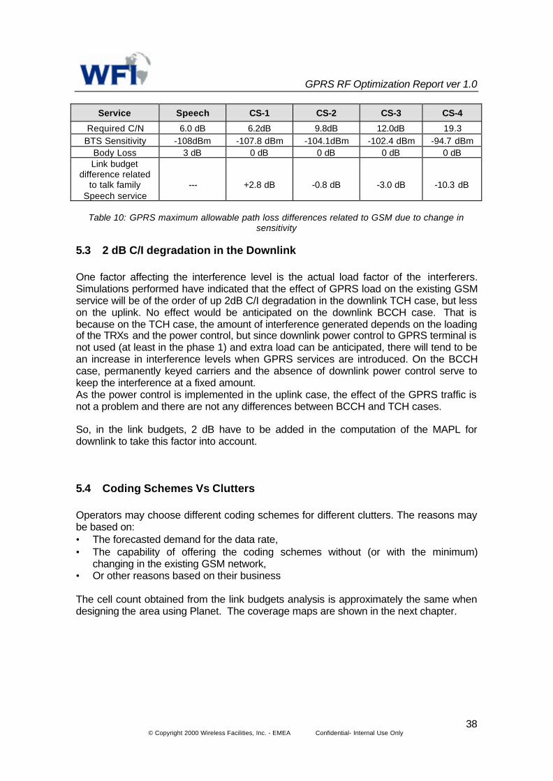
GPRS RF Optimization Report ver 1.0
© Copyright 2000 Wireless Facilities, Inc. - EMEA Confidential- Internal Use Only38
Service Speech CS-1 CS-2 CS-3 CS-4
Required C/N 6.0 dB 6.2dB 9.8dB 12.0dB 19.3BTS Sensitivity -108dBm -107.8 dBm -104.1dBm -102.4 dBm -94.7 dBm
Body Loss 3 dB 0 dB 0 dB 0 dB 0 dBLink budget
difference relatedto talk family
Speech service--- +2.8 dB -0.8 dB -3.0 dB -10.3 dB
Table 10: GPRS maximum allowable path loss differences related to GSM due to change insensitivity
5.3 2 dB C/I degradation in the Downlink
One factor affecting the interference level is the actual load factor of the interferers.Simulations performed have indicated that the effect of GPRS load on the existing GSMservice will be of the order of up 2dB C/I degradation in the downlink TCH case, but lesson the uplink. No effect would be anticipated on the downlink BCCH case. That isbecause on the TCH case, the amount of interference generated depends on the loadingof the TRXs and the power control, but since downlink power control to GPRS terminal isnot used (at least in the phase 1) and extra load can be anticipated, there will tend to bean increase in interference levels when GPRS services are introduced. On the BCCHcase, permanently keyed carriers and the absence of downlink power control serve tokeep the interference at a fixed amount.As the power control is implemented in the uplink case, the effect of the GPRS traffic isnot a problem and there are not any differences between BCCH and TCH cases.
So, in the link budgets, 2 dB have to be added in the computation of the MAPL fordownlink to take this factor into account.
5.4 Coding Schemes Vs Clutters
Operators may choose different coding schemes for different clutters. The reasons maybe based on:• The forecasted demand for the data rate,• The capability of offering the coding schemes without (or with the minimum)
changing in the existing GSM network,• Or other reasons based on their business
The cell count obtained from the link budgets analysis is approximately the same whendesigning the area using Planet. The coverage maps are shown in the next chapter.

GPRS RF Optimization Report ver 1.0
© Copyright 2000 Wireless Facilities, Inc. - EMEA Confidential- Internal Use Only39
6 Coverage Analysis
6.1 Coverage case study 1
Based on the Link Budgets Analysis we designed a GSM network for the city Paris. Thetotal area considered for the design is approximately for 100 km2 including 40 km2 ofdense urban, 35 km2 urban, 1 km2 suburban and 1 km2 rural and open area.
6.1.1 GSM Coverage for Paris within the periphery area
Figure 9: GSM Coverage for Paris
CoverageOpen/Rural outdoor Level: -87.6 dBm
Open/rural Incar Level: -81.6 dBm
Suburban-Indoor Level: -71.3 dBm
Urban-Indoor Level: -67dBm

GPRS RF Optimization Report Ver 4.0
© Copyright 2000 Wireless Facilities, Inc. - EMEA Confidential- Internal Use Only 40
Figure 10: Details of the coverage
The above table shows the covered area with the required threshold for Dense urban forGSM signal for different clutters.

GPRS RF Optimization Report Ver 4.0
© Copyright 2000 Wireless Facilities, Inc. - EMEA Confidential- Internal Use Only 41
6.1.2 GPRS Coverage for Paris within the periphery area for CS1
Figure 11: GPRS CS1 Coverage
CoverageCoding Scheme-1 Level: -71.8 dBm
Coding Scheme-2 Level: -68.1 dBm
Coding Scheme-3 Level: -66.4 dBm
Coding Scheme-4 Level: -58.7dBm

GPRS RF Optimization Report Ver 4.0
© Copyright 2000 Wireless Facilities, Inc. - EMEA Confidential- Internal Use Only 42
Figure 12: Details of coverage for CS1
The above table shows the covered area with the required threshold for GPRS Codingscheme 1 for different clutters. As we see comparing to the GSM coverage CS1 gives usa better coverage than GSM.

GPRS RF Optimization Report Ver 4.0
© Copyright 2000 Wireless Facilities, Inc. - EMEA Confidential- Internal Use Only 43
6.1.3 GPRS Coverage for Paris within the periphery area for CS2
Figure 13: GPRS coverage for CS2
CoverageCoding Scheme-1 Level: -71.8 dBm
Coding Scheme-2 Level: -68.1 dBm
Coding Scheme-3 Level: -66.4 dBm
Coding Scheme-4 Level: -58.7dBm

GPRS RF Optimization Report Ver 4.0
© Copyright 2000 Wireless Facilities, Inc. - EMEA Confidential- Internal Use Only 44
Figure 14: Details of coverage for CS2
The above table shows the covered area with the required threshold for GPRS Codingscheme 2 for different clutters. As we could expect from the Link Budgets results CS2coverage is almost the same as GSM coverage. That means with an existing GSMnetwork we can meet at least the GPRS CS2 threshold.

GPRS RF Optimization Report Ver 4.0
© Copyright 2000 Wireless Facilities, Inc. - EMEA Confidential- Internal Use Only 45
6.1.4 GPRS Coverage for Paris within the periphery area for CS3
Figure 15: GPRS coverage for CS3
CoverageCoding Scheme-1 Level: -71.8 dBm
Coding Scheme-2 Level: -68.1 dBm
Coding Scheme-3 Level: -66.4 dBm
Coding Scheme-4 Level: -58.7dBm
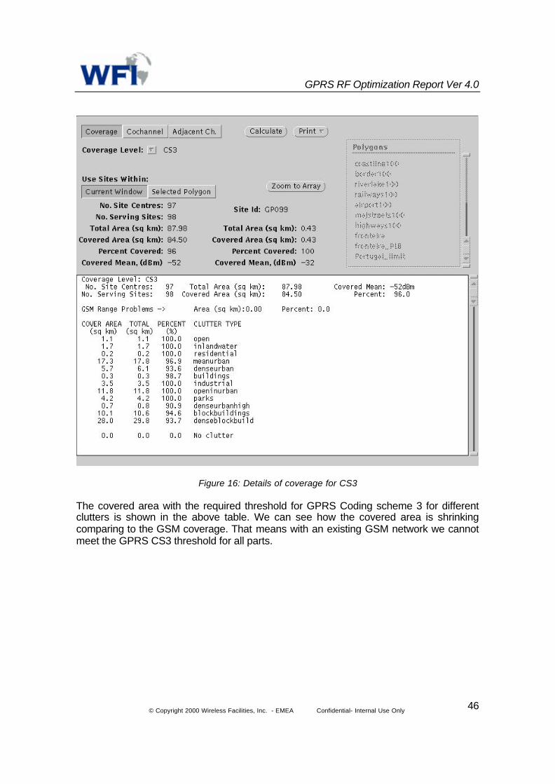
GPRS RF Optimization Report Ver 4.0
© Copyright 2000 Wireless Facilities, Inc. - EMEA Confidential- Internal Use Only 46
Figure 16: Details of coverage for CS3
The covered area with the required threshold for GPRS Coding scheme 3 for differentclutters is shown in the above table. We can see how the covered area is shrinkingcomparing to the GSM coverage. That means with an existing GSM network we cannotmeet the GPRS CS3 threshold for all parts.

GPRS RF Optimization Report Ver 4.0
© Copyright 2000 Wireless Facilities, Inc. - EMEA Confidential- Internal Use Only 47
6.1.5 GPRS coverage for Paris within the periphery area for CS4
Figure 17: GPRS coverage for CS4
CoverageCoding Scheme-1 Level: -71.8 dBm
Coding Scheme-2 Level: -68.1 dBm
Coding Scheme-3 Level: -66.4 dBm
Coding Scheme-4 Level: -58.7dBm

GPRS RF Optimization Report Ver 4.0
© Copyright 2000 Wireless Facilities, Inc. - EMEA Confidential- Internal Use Only 48
Figure 18: Details of coverage for CS4
The above table shows the covered area with the required threshold for GPRS Codingscheme 4 for different clutters. As we can see the covered area in the objective areas isshrinking to 1/3 to 1/5 comparing to the GSM coverage. That means with an existingGSM network we can not meet the GPRS CS4 threshold.

GPRS RF Optimization Report Ver 4.0
© Copyright 2000 Wireless Facilities, Inc. - EMEA Confidential- Internal Use Only 49
6.2 Coverage Case Study 2
In some cases due to the nature of the network there might be more sites available thanrequired for a specific coding scheme. In this case the radio interface can simply beoptimised to respond to the requirement of the throughput. For example as shownbelow a is the same area analysed in case study 1. But here the design shows 240 sitesto cover traffic issues.
6.2.1 GSM Coverage for Paris within the periphery area with 240 sites
Figure 19: GSM Coverage for 240 sites
Coverage
Open/Rural outdoor Level: -87.6 dBm
Open/rural Incar Level: -81.6 dBm
Suburban-Indoor Level: -71.3 dBm
Urban-Indoor Level: -67dBm

GPRS RF Optimization Report Ver 4.0
© Copyright 2000 Wireless Facilities, Inc. - EMEA Confidential- Internal Use Only 50
Figure 20: Details of the coverage for GSM with 240 sites
The above table shows the covered area with the required threshold for Dense urban forGSM signal for different clutters.

GPRS RF Optimization Report Ver 4.0
© Copyright 2000 Wireless Facilities, Inc. - EMEA Confidential- Internal Use Only 51
6.2.2 GPRS Coverage for Paris within the periphery area for CS1 with 240 sites
Figure 21: GPRS CS-1 coverage for 240 sites
CoverageCoding Scheme-1 Level: -71.8 dBm
Coding Scheme-2 Level: -68.1 dBm
Coding Scheme-3 Level: -66.4 dBm
Coding Scheme-4 Level: -58.7dBm
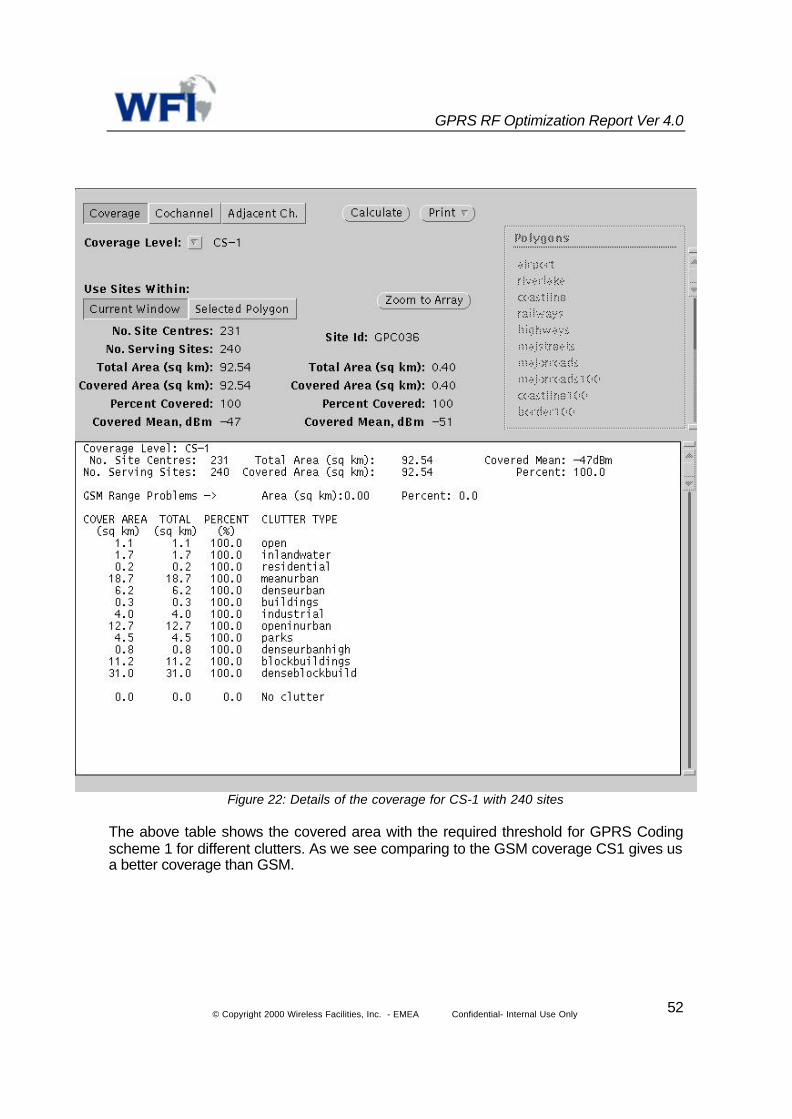
GPRS RF Optimization Report Ver 4.0
© Copyright 2000 Wireless Facilities, Inc. - EMEA Confidential- Internal Use Only 52
Figure 22: Details of the coverage for CS-1 with 240 sites
The above table shows the covered area with the required threshold for GPRS Codingscheme 1 for different clutters. As we see comparing to the GSM coverage CS1 gives usa better coverage than GSM.

GPRS RF Optimization Report Ver 4.0
© Copyright 2000 Wireless Facilities, Inc. - EMEA Confidential- Internal Use Only 53
6.2.3 GPRS Coverage for Paris within the periphery area for CS2 with 240 sites
Figure 23: GPRS CS-2 coverage for 240 sites
CoverageCoding Scheme-1 Level: -71.8 dBm
Coding Scheme-2 Level: -68.1 dBm
Coding Scheme-3 Level: -66.4 dBm
Coding Scheme-4 Level: -58.7dBm

GPRS RF Optimization Report Ver 4.0
© Copyright 2000 Wireless Facilities, Inc. - EMEA Confidential- Internal Use Only 54
Figure 24: Details of the coverage for CS-2 with 240 sites
The above table shows the covered area with the required threshold for GPRS Coding scheme 2 fordifferent clutters. As we see comparing to the GSM coverage CS2 gives us a better coverage thanGSM.

GPRS RF Optimization Report Ver 4.0
© Copyright 2000 Wireless Facilities, Inc. - EMEA Confidential- Internal Use Only 55
6.2.4 GPRS Coverage for Paris within the periphery area for CS3 with 240 sites
Figure 25: GPRS CS-3 coverage for 240 sites
CoverageCoding Scheme-1 Level: -71.8 dBm
Coding Scheme-2 Level: -68.1 dBm
Coding Scheme-3 Level: -66.4 dBm
Coding Scheme-4 Level: -58.7dBm

GPRS RF Optimization Report Ver 4.0
© Copyright 2000 Wireless Facilities, Inc. - EMEA Confidential- Internal Use Only 56
Figure 26: Details of the coverage for CS-3 with 240 sites
The covered area with the required threshold for GPRS Coding scheme 3 for differentclutters, is shown in the above table. We can see how the covered area is almost thesame as GSM coverage. That means with an existing GSM network we can meet atleast the GPRS CS3 threshold for this network.

GPRS RF Optimization Report Ver 4.0
© Copyright 2000 Wireless Facilities, Inc. - EMEA Confidential- Internal Use Only 57
6.2.5 GPRS Coverage for Paris within the periphery area for CS4 with 240 sites
Figure 27: GPRS CS-4 coverage for 240 sites with 240 sites
CoverageCoding Scheme-1 Level: -71.8 dBm
Coding Scheme-2 Level: -68.1 dBm
Coding Scheme-3 Level: -66.4 dBm
Coding Scheme-4 Level: -58.7dBm

GPRS RF Optimization Report Ver 4.0
© Copyright 2000 Wireless Facilities, Inc. - EMEA Confidential- Internal Use Only 58
Figure 28: Details of the coverage for CS-4
The above table shows the covered area with the required threshold for GPRS Codingscheme 4 for different clutters. As we can see the covered area in the objective areas isshrinking comparing to the GSM coverage. That means we cannot meet the GPRS CS4threshold for this network.

GPRS RF Optimization Report Ver 4.0
© Copyright 2000 Wireless Facilities, Inc. - EMEA Confidential- Internal Use Only 59
7 Capacity Dimensioning
The notion of running a new data service on residue capacity in the GSM network mayseem at first to relegate GPRS to the status of a second class service. However, a fewsimple calculations will show us that the residue capacity in a typical cell is more thanenough to provide a high level of service to IP traffic. Table 2 shows the capacity of ashared 4 carriers (30 channel) cell operating at a circuit switched blocking level of 1% - atypical design level.
Cell capacity 30 channelsCircuit switched capacity @ 1% blocking 20 Erlangs, i.e 20
channels averageResultant capacity for IP data traffic 10 channelsResultant end user IP throughput available 1 100kbit/sNote 1: assumes Coding Scheme 2 (CS2) ie approximately 10kbit/s per channel.
Table 11: Typical loading capability of a GSM cell (4 carriers)
What this tells us is that in a cell where we can support an average of 20 voice users wecan also support a data throughput of 100kbit/s. If each of the data users requires anaverage throughput of 5kbit/s (not untypical in a bursty data environment) the cell canalso support 20 data users. In practice since only 10-20% of data users will want totransfer data simultaneously, the peak data rate available per user will be in the region of25 – 50kbit/s.
This simplistic calculation needs to be refined to take account of the probability ofmultiple users all requiring instantaneous transmission of large files of data, but inpractice when such occasions arise the end result will simply be that all users willexperience slow data transfer, the files will still transfer successfully.
Theoretically a GSM network having 2% blocking and having 1 TRX a sector will have traffic2.9 Erlangs. This means there is 7 timeslots available for usage. A cell offering a circuit-switched load of 2.9 Erlangs with 7 circuits will, on average, have 4.1 spare circuits.However, there is a certain overhead associated with the division of the circuit-switched areaand the GPRS area. Due to this reason by simulation tests done the available circuits forGPRS is reduced from 4.1 to 3.1 circuits. On the other hand if this overhead in notconsidered this will lead to adverse effects of increased blocking percentage. Therefore themean free time slots in a circuit-switched environment will be 1. This can be extended to 14,22 etc timeslots depending on the traffic with a blocking of 2% as shown in the table below .

GPRS RF Optimization Report Ver 4.0
© Copyright 2000 Wireless Facilities, Inc. - EMEA Confidential- Internal Use Only 60
No of TRX (TCH) GSM Traffic @ 2%blocking (Erl)
Mean free TCH forGPRS (2%blocking)
Mean free TimeSlots in Circuit
Switch1(7) 2.9 3.1 1.02(14) 8.2 4.3 1.53(22) 14.9 5.6 1.54(30) 21.9 5.6 2.55(38) 29.2 5.8 3.06(46) 36.5 6.5 3.07(54) 43.9 7.1 3.08(62) 51.5 6.5 4.0
Table 12: Mean free time slots for GPRS in a circuit-switch
What the foregoing example tells us is that for a large number of cells in a GSM network,the existing capacity of the network will suffice to provide a good quality data service to alarge community of data customers. In practice, the take-up of GPRS will not beinstantaneous across the GSM customer base from day one, so it will be possible tomonitor usage and performance as GPRS usage grows, to validate performanceexpectations.
There are a number of cases where the existing capacity of a GSM network will not besufficient to provide a satisfactory level of service to GPRS users:
- In existing network hotspots, where the circuit switched network is congested.- In locations where high usage of GPRS data service is encountered (e.g. in-
building cells)- In multilayer networks where one layer of the network is used in high
utilization mode – ie where the blocking level on circuit switched traffic isknowingly driven up in order to achieve high levels of channel utilization.
In all these cases, additional carrier capacity must be provided to offer GPRS trafficsuitable throughput.
The real answer to the radio network dimensioning challenge will come from experience.Experience will tell us whether the busy hour for voice traffic (circuit switched) coincideswith that for data traffic. Experience will also tell us whether the geographic spread ofdata usage matches that of voice. Finally, experience will tell us what sort of usecustomers make of GPRS, what sort of file sizes are transported, and what sort ofspeeds they require. Careful monitoring of loading and service levels experienced onGPRS in the growth phase of the service will enable dimensioning decisions to be madeahead of growth.
All the foregoing analysis and discussion has assumed provision of equal performanceacross GPRS users on a GSM network. However, the GPRS standards proved for usersto be given differential service levels. In particular, users may be offered a precedenceclass that promotes their data to ‘ first in the queue’ when encountering shared radio (orCore network) resources. Once this feature is developed by equipment vendors it will bepossible to offer a subset of GPRS users premium service, guaranteeing high levels ofthroughput even if the cell they are in is heavily loaded.

GPRS RF Optimization Report Ver 4.0
© Copyright 2000 Wireless Facilities, Inc. - EMEA Confidential- Internal Use Only 61
7.1 Network Performance
The two major measures of GPRS performance are:• Peak Throughput: the rate at which data is transferred• Latency: the time taken for data packets to pass through the GPRS bearer
7.1.1 Peak Throughput
An overview of GPRS peak throughputs based on the number of timeslosts available inGPRS handsets, and the Coding Schemes supported by the network is shown in Table13.
Timeslots CS-1 (kbps)Raw throughput/
Useable data
CS-2 (kbps)Raw throughput/
Useable data1 9.05/7.41 13.4/11.112 18.1/14.29 26.8/22.223 27.15/22.22 40.2/33.334 36.2/28.57 53.6/40
Table 13 Typical GPRS Peak Throughputs
The key drivers for peak throughput are:• Mobile terminal timeslots / available radio capacity• Radio coding scheme• Protocol overhead• Radio blocking level
Timeslots - As shown in the table, the number of timeslots (TS) that a mobile terminalhas will drive the peak throughput. Initial GPRS terminals are expected to be on theorder of 1 TS uplink and 2 TS downlink (1U/2D). Future handsets are likely to have atleast 4 TS downlink, and perhaps multiple uplink TSs. It is also important to rememberthat the throughputs in Table 16 are ‘peak’ throughputs and are only achievable if thereis sufficient capacity available in the radio network support them. In busy times whenmultiple GSM and GPRS users are vying for the same timeslots, the actual throughputwill vary and will often be well below the peak level.
Coding Schemes - The second key driver of throughput is the radio interface codingscheme. As shown in Table 16, higher coding schemes offer greater throughputs.GPRS offers four coding schemes, but initial supplier GPRS radio infrastructure offeringsare expected to be limited to CS-1 and CS-2. Higher CS coding levels also result ingreater C/I levels which results in reduced coverage areas. For CS-2 the coverage areais not significantly lower that CS-1, but coverage is progressively reduced for CS-3 andCS-4. Due to the reliability of CS1 this coding scheme is always used for signallingpackets. Whereas it is planned that a bursty data transfer always start with CS1 for thefirst data packets. The resource management shall use a higher CS if it is possible.The actual performance of each of these CS is dependent upon the chanel C/I. The
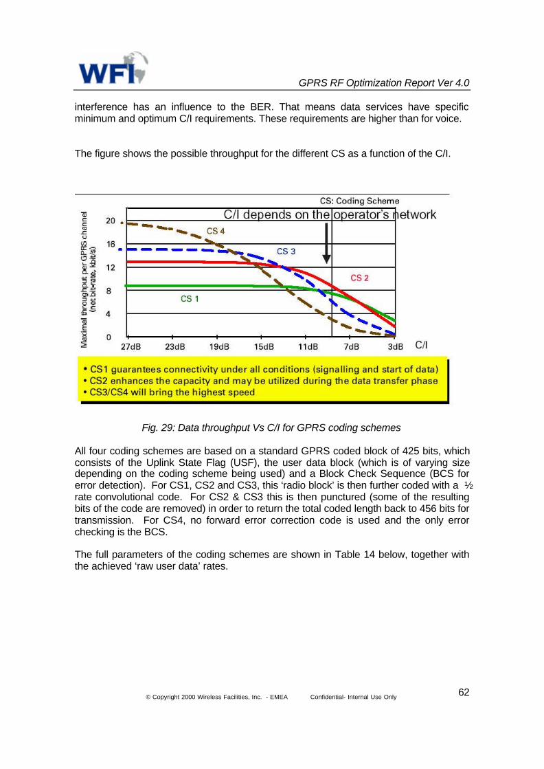
GPRS RF Optimization Report Ver 4.0
© Copyright 2000 Wireless Facilities, Inc. - EMEA Confidential- Internal Use Only 62
interference has an influence to the BER. That means data services have specificminimum and optimum C/I requirements. These requirements are higher than for voice.
The figure shows the possible throughput for the different CS as a function of the C/I.
Fig. 29: Data throughput Vs C/I for GPRS coding schemes
All four coding schemes are based on a standard GPRS coded block of 425 bits, whichconsists of the Uplink State Flag (USF), the user data block (which is of varying sizedepending on the coding scheme being used) and a Block Check Sequence (BCS forerror detection). For CS1, CS2 and CS3, this ‘radio block’ is then further coded with a ½rate convolutional code. For CS2 & CS3 this is then punctured (some of the resultingbits of the code are removed) in order to return the total coded length back to 456 bits fortransmission. For CS4, no forward error correction code is used and the only errorchecking is the BCS.
The full parameters of the coding schemes are shown in Table 14 below, together withthe achieved ‘raw user data’ rates.

GPRS RF Optimization Report Ver 4.0
© Copyright 2000 Wireless Facilities, Inc. - EMEA Confidential- Internal Use Only 63
CodingScheme
Coderate
USFbits
Pre-codedUSFbits
RadioBlock bitsexcl. USFand BCS
BCSbits
Tailbits
Codedbits
Puncturedbits
RawUserData ratekb/s
CS-1 ½ 3 3 181 40 4 456 0 9.05CS-2 ≈2/3 3 6 268 16 4 588 132 13.4CS-3 ≈3/4 3 6 312 16 4 676 220 15.6CS-4 1 3 12 428 16 - 456 - 21.4
Table 14: Coding Parameters for the Coding Schemes.
7.2 System C/I Profile and Mean Data Rate per Channel
The C/I for a given user will depend on the location within the cell. Depending on the C/Iratio and the frequency reuse factor, the probability of the C/I range within the cell foreach reuse factor can be compared.
Taking into consideration of a lognormal fading (Standard deviation of 7) simulation testsshow typical C/I distributions for different reuse patterns. This is show in the figure 30below.
Figure 30: C/I distribution, 3-sector sites, 65 degree antennas, K=3,9 and 12
Also the data rate depends on the C/I and the coding schemes used. The figure 31below shows the comparison of data rates for different C/I intervals.

GPRS RF Optimization Report Ver 4.0
© Copyright 2000 Wireless Facilities, Inc. - EMEA Confidential- Internal Use Only 64
Figure 31: Typical data rate per C/I interval
Considering the probability and data rate for each C/I interval the mean data rate can becalculated using the formula shown.
pr ii
iD ∑=
The results of the above formula are tabulated in the Table Y below showing for omni, sector,reuse patterns and the data rate for the coding schemes.
Configuration Mean data rate (optimum)kbps
(CS-1 and 2)
Mean data rate (optimum)kbps
(CS-1, 2, 3 and 4)Omni, K=3 9.8 12.4Omni, K=9 12.5 17.3Omni, K=12 12.8 18.2
3-Sector, K=3 11.4 15.13-Sector, K=9 12.9 18.73-Sector, K=12 13.1 19.3
Table 15: Mean data rate per channel for different coding schemes and configurations

GPRS RF Optimization Report Ver 4.0
© Copyright 2000 Wireless Facilities, Inc. - EMEA Confidential- Internal Use Only 65
Protocol Overhead – This causes the true user throughput to be significantly less thanthe peak raw throughput. The ‘raw user data’ rates assume an error free channel, andexclude any higher layer protocol overheads, such as TCP/IP, and the link establishmentand control overheads. Therefore, the ‘true peak user throughput’ rates for any of thesecoding schemes will be lower, as shown earlier in Table 14.
An overview of the GPRS protocols that impact the useable peak data rate is shownbelow in Table 16.
CS2, 2 TS CS2, 4 TSApplication Data 20.44kb/s 40.88 kb/sTCP/IP 22.2 kb/s 44.44 kb/sSNDCP 22.32 kb/s 44.64 kb/sLogical Link 22.62 kb/s 45.24 kb/sRadio Link 23.2 kb/s 46.4 kb/sRadio Layer 26.8 kb/s 53.6 kb/s
Table 16 : Impact of GPRS protocol overheads on peak throughput
By adding headers and error detection trailers, each protocol reduces the effectiveamount of useable data that is transmitted with a given packet. The method used for thenumbers quoted in Table 6 for useable data is the throughput that includes the TCP/IPoverhead. This is consistent with data rates quoted for other Internet communications;however, TCP/IP itself adds a 40 bytes header per packet, leaving the final peakthroughout of actual application data at 6.81 kbps for CS-1 or 10.22 kbps for CS-2,assuming no header compression.
Radio Blocking – Finally, the actual useable peak throughput will be influenced by thequality of the radio environment. The numbers for useable throughput described in thissection is all based on an ideal radio environment. The useable throughput achieved ina real world radio environment is likely to be less than this, and can vary widely atdifferent times and locations in the network based on radio blocking levels and numberof required re-transmissions.
7.2.1 Latency
The major elements of latency and representative latency figures are provided below inTable 17.
Latency Element Uplink TBFEstablishment1TS
OngoingUplink Latency1 TS
Downlink TBFEstablishment2TS
OngoingDownlinkLatency 2TS
MS Delay 250 ms 100 ms 150 ms 150 ms
TBF Establishment 400 ms 0 1000 ms 0

GPRS RF Optimization Report Ver 4.0
© Copyright 2000 Wireless Facilities, Inc. - EMEA Confidential- Internal Use Only 66
Over the Air Delay 400 ms 400 ms 200 ms 200 ms
SGSN/GGSNLatency
50 ms 50 ms 50 ms 50 ms
Total 1.1 seconds 0.55 seconds 1.4 seconds 0.4 seconds
Table 17: GPRS Latency Examples for 1 TS Uplink, and 2TS Downlink
These latency calculations are from the Mobile Station (MS) to the Gi GGSN interface toexternal networks. Any delays in external to the GPRS network from interconnections viathe Internet or in application processing are not included.
In this example, a round trip ‘ping’ which measures the time to send a packet to a serveroutside the network and receive a response, the total time would be at approximately 2.5seconds (1.1 uplink plus 1.4 downlink). Based on a 500 ms variance, a round trip ‘ping’should generally take 2-3 seconds since radio resources must be allocated for a onetime ping. Subsequent transfers would only require about one second round trip as longas the radio resources are allocated to GPRS, since Temporary Block Flow (TBF)establishment would not be necessary.
The actual latency experienced by the user could also vary based on the specific waythe infrastructure is implemented by suppliers and the applications accessed. Moreoperational experience is required to understand which types of applications will requirefrequent TBF set-ups and hence have greater latency.
The key elements of GPRS latency are defined below:
RLC Block Error Rate - the time taken to retransmit erroneous information due to errorscaused by the hostile radio environment. This rate is highly variable depending on radioconditions. For the purposes of the examples in Table 17, ideal radio conditions areassumed and no delay is accounted for.
Mobile Station (MS) delay - the time taken by the Mobile Station (MS) to process an IPdatagram and request radio resource. This includes the delay from the PC to MS, andthe MS processing time. This delay is typically less than 100ms, with the exception ofthe processing to establish a request for an uplink TBF channel, which could be in theorder of 100-200 ms.
Temporary Block Flow (TBF) Establishment/Cleardown Time - the time it takes theBSS/PCU to provide and release the radio resources required by the user to enable datatransfer to take place in either the uplink or downlink. This only occurs on the firsttransmission, and is not required for subsequent transmissions as long as the resourcesare allocated to GPRS. The time for TBF establishment can be on the order of 500 msto 1s and is independent upon the amount of data to be transferred.
Throughput over the air delay - the rate at which user data is physically transmitted fromthe MS to the SGSN once a TBF is established. This delay is directly related to the sizeof the IP datagram being sent. The smaller the packet sizes the shorter the delay. For

GPRS RF Optimization Report Ver 4.0
© Copyright 2000 Wireless Facilities, Inc. - EMEA Confidential- Internal Use Only 67
the examples used we are assuming an MTU (Message Transmission Unit) of 400- 600kbytes for a 400ms delay for 1 TS. This delay is proportionally reduced for multipletimeslot MSs.
SGSN/GGSN delay - the delay for the packet to transit through the SGSN and GGSN.This should be almost negligible, and is assumed to be less than 50ms.
8 Capacity case study
Generic impact of the migration of GSM towards GPRS on capacity
The report investigates GPRS migration and its impact on existing GSM network capacity.The following example aims to shed light on the various options available to the networkplanners.
Assumptions
• The city comprises of 30,000 subscribers
• A city is covered by 9 base stations regularly locatedin a grid (3x3)
• Each base station is 3-sectored with 3 TRXs persector
• Traffic demand is almost uniform geographically
• 20mErlang per subscriber during busy hour- GSM
• 2% blocking probability
• For GPRS Coding schemes 1 & 2 will be offered
8.1 Case one: Adding TRXs without considering dedicated TSLs to GPRSusers
There are 9 sites (all with three sectors). So the number of the subscribers per sector willbe:
30000 / 27 = 1111.1111 Subscribers
The required traffic per sector:
1111.1111 x 20 mE = 22.2222 Erlangs/ sector
Considering 2% blocking, from the Erlang B table 14.9 Erlangs can offered with 3 TRXsper sector. However the traffic offered is 22.22 Erlangs. Therefore the network suffers

GPRS RF Optimization Report Ver 4.0
© Copyright 2000 Wireless Facilities, Inc. - EMEA Confidential- Internal Use Only 68
with a 15.7% blocking which is not acceptable. So we need to increase the TRXs tomeet the required blocking.
According to the Erlang-B equation we can offer a 21.9 Erlangs traffic with 4 TRXs for2% blocking. The traffic offered is 22.22 Erlangs. This is very close to our need but isstill not enough.So let’s try to find how many more TRXs we need after adding one TRX to each sector.
With 4 TRXs/sec sites we will offer:
21.9 x 27= 591.3 Erlangs traffic offered
While the demand for traffic is:
30000 x 0.020 = 600 Erlang
That means we still need to offer 8.7 Erlangs more:
600 – 591.3 = 8.7 Erlangs
for offering an additional of 8.7 Erlang we need to change some of the sectors to 5TRXsfrom 4TRXs. Any change from 4TRXs to 5TRXs gives us 7.3 Erlang more for thatsector:
29.2 [the traffic offered by 5TRXs] – 21.9 [the traffic offered by 5TRXs] = 7.3 Erlangsmore8.7 [the required traffic] / 7.3 = 1.4 sectors or approximately 2 sectors. In other words2 sectors will have to be upgraded with 5 TRXs.
This can be achieved by adding only two more TRXs in total. (i.e. all the sectors shouldbe up graded to 4 TRXs except two of them that should be 5 TRXs).In fact, in a real network we usually don’t have a uniform traffic and it is very likely tohave more traffic in some regions. In that case, with taking the statistics into accountthese two sectors can be chosen.
8.1.1 GPRS migration
According to Table 12 the number of free time slots in a circuit switched territory for4TRXs sectors we have to leave 2.5 TSLs in order to not to exceed 2% blocking duringGPRS usage.
We have then:
TSL available for GPRS = Total channels - used traffic - 2.5= 30 - 21.9 - 2.5= 5.6 Timeslots available for GPRS
The mean data rate per Timeslot for CS1 & CS2 having the frequency reuseconfiguration of 3 sec./ 9 is 12.9 kbps. That means:

GPRS RF Optimization Report Ver 4.0
© Copyright 2000 Wireless Facilities, Inc. - EMEA Confidential- Internal Use Only 69
Total Data Rate in Cell = 12.9 x 5.6 = 72.24 kbps (in busy hour)
According to the number of free time slots in a circuit switched territory for 5TRXssectors we have to leave 3 TSLs in order not to exceed 2% blocking during GPRSusage.
We have then:
TSL available for GPRS = Total channels - used traffic - 3= 38 – (21.9 + 8.7/2) - 3= 8.7 Timeslots available for GPRS in the 5TRXs sectors
That means:
Total Data Rate in Cell = 12.9 x 8.7 = 112.23 kbps (in busy hour)
8.2 Case two: Adding TRXs with considering two dedicated TSLs to GPRSusers
In this case we consider two dedicated TSLs for each sector. There are 9 sites (all withthree sectors). So the number of the subscribers per sector will be:
30000 / 27 = 1111.1111 Subscribers
The required traffic per sector:
1111.1111 x 20 mE = 22.2222 Erlangs/ sector
Considering 2% blocking, from the Erlang B table 14.9 Erlangs are offered with 3 TRXsper sector. From the previous analysis this network suffered from 15.7% blocking whichis not acceptable. Again the situation will be even worse with the GPRS usage. Becauseafter assigning two TSLs for GPRS, GSM traffic will we left out with 20 TSLs whichcauses 21.5% blocking. So we need to increase the TRXs to meet the required blocking.
The number of available TSLs for GSM after dedicating two channels for GPRS will be:
Considering 4 TRXs per sector Available TSLs for GSM= 32 – 2 [for control channels] –2 [for GPRS] = 28 TSLs
According to the Erlang-B equation we can offer a 20.2 Erlangs traffic with 4 TRXs (28TSLs) for 2% blocking. This is close to our need but is still not enough.So let’s try to find how many more TRXs we need after adding one TRX to each sector.
With 4 TRXs/sec sites we will offer:
20.2 x 27= 545.4 Erlangs traffic offered

GPRS RF Optimization Report Ver 4.0
© Copyright 2000 Wireless Facilities, Inc. - EMEA Confidential- Internal Use Only 70
While the demand for traffic is:
30000 x 0.020 = 600 Erlang
That means we still need to offer 54.6 Erlangs more:
600 – 545.4 = 54.6 Erlangs
The available TSLs for GSM with 5 TRXs are:
Available TSLs for GSM= 40 – 2 [for control channels] – 2 [for GPRS] = 36 TSLs
According to the Erlang-B equation we can offer a 27.4 Erlangs traffic with 5 TRXs (36TSLs) for 2% blocking. Which 20.2 of it is already considered. That means for eachsector with 5 TRXs 7.2 more Erlangs is offered. The no. of the 5 TRXs sectors can befound then:
27.4 [Erlangs offered by 5TRXs] – 20.2 [Erlangs offered by 4TRXs] = 7.2 [Erlangsadded]
And:
Number of Sectors with 5 TRXs = 54.6 / 7.2 = 7.6 (or 8 sectors)
8.2.1 GPRS migration
According to the Table 12 number of free time slots in a circuit switched territory for4TRXs sectors we have to leave 2.5 TSLs in order to not to exceed 2% blocking duringGPRS usage.
We have then:
TSL available for GPRS = Total channels - used traffic - 2.5= 30 – 20.2 - 2.5= 7.3 Timeslots available for GPRS
The mean data rate per Timeslot for CS1 & CS2 having the frequency reuseconfiguration of 3 sec./ 9 is 12.9 kbps. That means:
Total Data Rate in Cell = 12.9 x 7.3 = 94.17 kbps (in GSM busy hour)
According to the number of free time slots in a circuit switched territory for 5TRXssectors we have to leave 3 TSLs to not to exceed 2% blocking during GPRS usage.
We have then:
TSL available for GPRS = Total channels - used traffic - 3= 38 – (20.2 + 54.6/8) - 3

GPRS RF Optimization Report Ver 4.0
© Copyright 2000 Wireless Facilities, Inc. - EMEA Confidential- Internal Use Only 71
= 7.975 Timeslots available for GPRS in the 5TRXs sectors
That means:
Total mean Data Rate in Cell = 12.9 x 7.975 = 102.88 kbps (in busy hour)
For both 4 TRX sectors and 5 TRX sectors we will have the minimum data rate of:
12.9 x 2 [dedicated TSLs to GPRS] = 25.8 kbps
8.3 Case three: Adding new sites with considering two dedicated TSLs toGPRS users
The demanded traffic is:
0.020 x 30000 =600 Erlangs
The offered traffic is:
13.2 [for 20 TSLs] x 27 [sectors] = 356.4 Erlangs
so we need to offer 243.6 Erlangs more:
600 – 356.4 = 243.6 Erlangs
Then the required no. of sites (based on 3 TRXs per sector) will be:
243.6 / (13.2 x 3) = 6.15 Sites (or 7 sites)
8.3.1 GPRS migration
The traffic handled by each sector is:
600 [demanded traffic] / (9 + 7) x 3 = 12.5 ErlangsAccording to the Table 12 number of free time slots in a circuit switched territory for3TRXs sectors we have to leave 1.5 TSLs in order to not to exceed 2% blocking duringGPRS usage.
We have then:
TSL available for GPRS = Total channels - used traffic - 1.5= 24 – 2 [control] – 12.5 [used traffic] - 1.5= 8 Timeslots available for GPRS
The mean data rate per Timeslot for CS1 & CS2 having the frequency reuseconfiguration of 3 sec./ 9 is 12.9 kbps. That means:
Total mean Data Rate in Cell = 12.9 x 8 = 103.2 kbps (in GSM busy hour)

GPRS RF Optimization Report Ver 4.0
© Copyright 2000 Wireless Facilities, Inc. - EMEA Confidential- Internal Use Only 72
And the minimum data rate will be:
• 12.9 x 2 [dedicated TSLs to GPRS] = 25.8 kbps
9 Mobiles availability
Availability of GPRS handsets, which include: GSM/GPRS mobile Internet phones,Personal Digital Assistants with the GSM/GPRS PC Card modem or with a GSM/GPRSmobile Internet phone used as a modem and GSM/GPRS PC Card modems, is a bigfactor.
There are expected to be many more GPRS enabled phones coming to market over thenext six months. However, more critical right now to the development of the GPRSmarket is the availability of GPRS-enabled PDAs and other hand-held computingdevices. To date none of the popular PDA devices on the market has a networkapproved GPRS enabled version commercially available. Given the expectation that theGPRS market will build initially around business applications, this is a problem.
In the table below shows the available GPRS hand sets in the market.
9.1 Worldwide GPRS Terminals and Handsets
9/25/01
Vendor Model Frequency AvailableAlcatel One Touch 502
One Touch 700702
900/1800900/1800900/1800
Q2 2001Q4 2001Q4 2001
Audiovox GP710 YesEricsson R520
R600T39T65T68
900/1800/1900900/1800900/1800/1900900/1800900/1800/1900
YesQ4 2001 / Q1 2002YesQ4 2001Q4 2001
GTran Wireless Dot SurferPCMCIAWireless Dot SurferPCMCIA
1800 only900/1800/1900
Q3 2001Q4 2001
Maxon MX 7810 EGSM 900/GSM 1800 Q4 2001Mitsubishi / Trium
Trium G360Trium G520Trium GT550Trium EclipseTrium Geo GPRS
900/1800900/1800900/1800900/1800900/1800
Q3 2001Q1 2002Q1 2002AvailableAvailable
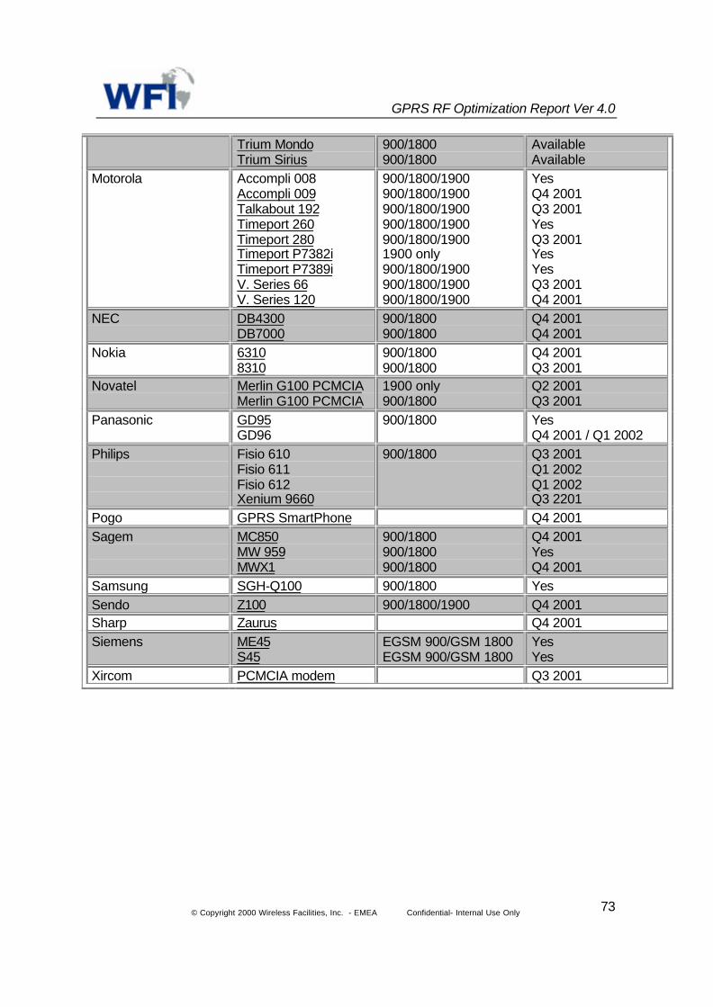
GPRS RF Optimization Report Ver 4.0
© Copyright 2000 Wireless Facilities, Inc. - EMEA Confidential- Internal Use Only 73
Trium MondoTrium Sirius
900/1800900/1800
AvailableAvailable
Motorola Accompli 008Accompli 009Talkabout 192Timeport 260Timeport 280Timeport P7382iTimeport P7389iV. Series 66V. Series 120
900/1800/1900900/1800/1900900/1800/1900900/1800/1900900/1800/19001900 only900/1800/1900900/1800/1900900/1800/1900
YesQ4 2001Q3 2001YesQ3 2001YesYesQ3 2001Q4 2001
NEC DB4300DB7000
900/1800900/1800
Q4 2001Q4 2001
Nokia 63108310
900/1800900/1800
Q4 2001Q3 2001
Novatel Merlin G100 PCMCIAMerlin G100 PCMCIA
1900 only900/1800
Q2 2001Q3 2001
Panasonic GD95GD96
900/1800 YesQ4 2001 / Q1 2002
Philips Fisio 610Fisio 611Fisio 612Xenium 9660
900/1800 Q3 2001Q1 2002Q1 2002Q3 2201
Pogo GPRS SmartPhone Q4 2001Sagem MC850
MW 959MWX1
900/1800900/1800900/1800
Q4 2001YesQ4 2001
Samsung SGH-Q100 900/1800 YesSendo Z100 900/1800/1900 Q4 2001Sharp Zaurus Q4 2001Siemens ME45
S45EGSM 900/GSM 1800EGSM 900/GSM 1800
YesYes
Xircom PCMCIA modem Q3 2001

GPRS RF Optimization Report Ver 4.0
© Copyright 2000 Wireless Facilities, Inc. - EMEA Confidential- Internal Use Only 74
SIEMENS, S45
Siemens´ first GPRS Phone, the S45, is an innovative mobile business tool with anoutstanding performance via high-speed data transfer and flexible memory

GPRS RF Optimization Report Ver 4.0
© Copyright 2000 Wireless Facilities, Inc. - EMEA Confidential- Internal Use Only 75
ERICSSON, T39
The T39 was first launched on the Swedish and Italian markets. Reaction fromconsumers has been positive.
T39 has plenty of features of interest to a broad market.To date, the T39 is available in stores all over Europe. And it will become available onthe Asian and U.S. markets shortly.
NOKIA, 6310
• Availability: Europe, Africa,Asia Pacific
• Key features: GPRS, HSCSD,Bluetooth, WAP 1.2.1, voicerecorder, voice commands, voicedialing
• Operating frequency: EGSM900/1800 networks in Europe,Africa and Asia Pacific

GPRS RF Optimization Report Ver 4.0
© Copyright 2000 Wireless Facilities, Inc. - EMEA Confidential- Internal Use Only 76
NOKIA, 8310
• Availability: Europe, Africa,Asia Pacific
• Key features: Latest look andfeel, WAP over GPRS,integrated FM radio, userchangeable front and backcovers, voice features
• Operating frequency: EGSM900/1800 networks in Europe,Africa, and Asia Pacific
MOTOROLA, P7389i
• Microbrowser for web access (01)
on the go
• Tri-band GSM 900/1800/1900MHz networks (provides roamingin select cities in Europe, Asia orAmerica)
• Built-In Microbrowser - accessDirections, Stock quotes, andAirline information, all wireless!(01)
• iTAP™ software for simplifiedtext entry - anticipates the wordyou are trying to spell whenentering text in email, shortmessages or other edit modes.
• Supports European OperatorsStandard - SMG 31
• International Access
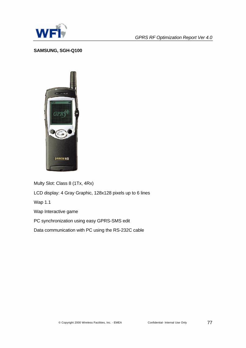
GPRS RF Optimization Report Ver 4.0
© Copyright 2000 Wireless Facilities, Inc. - EMEA Confidential- Internal Use Only 77
SAMSUNG, SGH-Q100
Multy Slot: Class 8 (1Tx, 4Rx)
LCD display: 4 Gray Graphic, 128x128 pixels up to 6 lines
Wap 1.1
Wap Interactive game
PC synchronization using easy GPRS-SMS edit
Data communication with PC using the RS-232C cable