Embed Size (px)
Citation preview
GPSMAPTM
215/225
OWNER’S MANUAL& REFERENCE
®
215225manb.qxd 4/27/00 9:22 AM Page 1

215225manb.qxd 4/27/00 9:22 AM Page 2

Software Version 2.12 or above
Internal Database Version 3.00 © 1998-2000 GARMIN Corporation
G-chart™ cartridge data is copyrighted and may not be copied or used for any other purposewithout permission.
GARMIN Corporation, 1200 E. 151st Street, Olathe, KS 66062 USA
Tel: 913.397.8200 Fax: 913.397.8282
GARMIN (Europe) Ltd., Unit 5, The Quadrangle, Abbey Park, Romsey, Hampshire SO51 9AQ UK
Tel: 44/1794.519944 Fax: 44/1794.519222
Garmin (Asia) Corp., No. 68, Jangshu 2nd Rd., Shijr, Taipei County, Taiwan
Tel: 886/02.2642.8999 Fax: 886/02.2642.9099
Web Site Address: www.garmin.com
© Copyright 1998-2000 GARMIN Corporation All Rights ReservedExcept as expressly provided herein, no part of this manual may be reproduced, copied, transmitted, disseminated, downloaded or stored in any storage medium, for any purpose without the express prior written consent of GARMIN Corporation. GARMIN Corporationhereby grants permission to download a single copy of this manual and of any revision to thismanual onto a hard drive or other electronic storage medium to be viewed and to print onecopy of this manual or of any revision hereto, provided that such electronic or printed copy ofthis manual or revision must contain the complete text of this copyright notice and providedfurther that any unauthorized commercial distribution of this manual or any revision hereto isstrictly prohibited. Information in this document is subject to change without notice. GARMINreserves the right to change or improve their products and to make changes in the content without obligation to notify any person or organization of such changes.
GARMIN, GPSMAP 215, GPSMAP 225, AutoLocate, TracBack, MapSource, and PhaseTrac12are all trademarks of GARMIN Corporation and may not be used without the expressed permis-sion of GARMIN.
April 2000 Part Number 190-00061-20 Rev. B Printed in Taiwan. i
INTRODUCTIONForeword
215225manb.qxd 4/27/00 9:22 AM Page i

ii
CAUTION: The Global Positioning System (GPS) is operated by the government ofthe United States, which is solely responsible for its accuracy and maintenance. The sys-tem is subject to changes which could affect the accuracy and performance of all GPSequipment. Although the GPSMAP is a precision electronic NAVigation AID (NAVAID),any NAVAID can be misused or misinterpreted and, therefore, become unsafe.
Use the GPSMAP at your own risk. To reduce the risk of unsafe operation, carefullyreview and understand all aspects of this Owner’s Manual and thoroughly practiceoperation using the simulator mode prior to actual use. When in actual use, carefullycompare indications from the GPSMAP to all available navigation sources includingthe information from other NAVAIDs, visual sightings, charts, etc. For safety, alwaysresolve any discrepancies before continuing navigation.
WARNING: The electronic chart is an aid to navigation designed to facilitate theuse of authorized government charts, not to replace them. Only official governmentcharts and notices to mariners contain all information needed for the safety of naviga-tion, and as always, the user is responsible for their prudent use.
CAUTION: The GPSMAP does not contain any user-serviceable parts. Repairsshould only be made by an authorized GARMIN service center. Unauthorized repairsor modifications could void your warranty and your authority to operate this deviceunder Part 15 FCC regulations.
INTRODUCTIONCautions
FCC Compliance
This device complies with Part 15 of the FCC limitsfor Class B digital devices. This equipment gener-ates, uses, and can radiate radio frequency energyand, if not installed and used in accordance with theinstructions, may cause harmful interference toradio communications.
There is no guarantee that interference will notoccur in a particular installation. If this equipmentdoes cause harmful interference to other equipment,which can be determined by turning the affectedequipment off and on, the user is encouraged to trycorrecting the interference by relocating the equip-ment or connecting the equipment to a different cir-cuit than the affected equipment. Consult an autho-rized dealer or service technician for additionalhelp.
Operation is subject to the following: (1) This devicecannot cause harmful interference, and (2) thisdevice must accept any interference received, includ-ing interference that may cause undesired operation.
I
I
I
215225manb.qxd 4/27/00 9:22 AM Page ii
iii
GARMIN Corporation warrants this product to be free from defects in materialsand manufacture for one year from the date of purchase. GARMIN will, at its soleoption, repair or replace any components that fail in normal use. Such repairs orreplacement will be made at no charge to the customer for parts or labor. The customer is, however, responsible for any transportation costs. This warranty does notcover failures due to abuse, misuse, accident or unauthorized alteration or repairs.
THE WARRANTIES AND REMEDIES CONTAINED HEREIN ARE EXCLUSIVEAND IN LIEU OF ALL OTHER WARRANTIES EXPRESS OR IMPLIED OR STATUTO-RY, INCLUDING ANY LIABILITY ARISING UNDER ANY WARRANTY OF MER-CHANTABILITY OR FITNESS FOR A PARTICULAR PURPOSE, STATUTORY OROTHERWISE. THIS WARRANTY GIVES YOU SPECIFIC LEGAL RIGHTS, WHICHMAY VARY FROM STATE TO STATE.
IN NO EVENT SHALL GARMIN BE LIABLE FOR ANY INCIDENTAL, SPECIAL,INDIRECT OR CONSEQUENTIAL DAMAGES, WHETHER RESULTING FROM THEUSE, MISUSE, OR INABILITY TO USE THIS PRODUCT OR FROM DEFECTS INTHE PRODUCT. SOME STATES DO NOT ALLOW THE EXCLUSION OF INCIDENTAL OR CONSEQUENTIAL DAMAGES, SO THE ABOVE LIMITATIONSMAY NOT APPLY TO YOU.
To obtain warranty service, call the GARMIN Customer Service department (913-397-8200) for a returned merchandise tracking number or contact yourGARMIN dealer. The unit should be securely packaged with the tracking numberclearly marked on the outside of the package and sent freight prepaid and insured to aGARMIN warranty service station. A copy of the original sales receipt is required asthe proof of purchase for warranty repairs. GARMIN retains the exclusive right torepair or replace the unit or software or offer a full refund of the purchase price at itssole discretion. SUCH REMEDY SHALL BE YOUR SOLE AND EXCLUSIVE REMEDYFOR ANY BREACH OF WARRANTY.
Serial Number
Use the area below to record the serial number (8-digit number located on the back of the unit) in case it is lost, stolen, or needs service. Be sure to keep your original sales receipt in a safe place or attach a photocopy inside the manual.
INTRODUCTIONLimited Warranty & Registration
RegistrationHelp us better support you by completing ouron-line registration today! Have the serialnumber of your GPSMAP 215/225 handy andconnect to our website at (www.garmin.com).Look for the Product Registration link on theHome page.
Why should you register your GPSMAP215/225?• Notification of Product Updates• Notification of New Products• Lost or Stolen unit tracking
NOTE: If you have previously registered yourGARMIN product purchase using a mail-inregistration card, we invite you to re-registerusing our NEW on-line system. Many servicesprovided by our new product registration system are now being automated and re-registering your purchase ensures you thebest possible support from GARMIN.
* *
215225manb.qxd 4/27/00 9:22 AM Page iii

The following optional accessories are available foryour GPSMAP system:
• G-chart Electronic Chart Cartridges• 110/220 Volt AC Adapter• Flush Mounting Kit• Cigarette Lighter Adapter• MapSource™ PC Software• PC Interface Cable• GA23 H-Field DGPS Antenna• GBR 21/23 DGPS Receivers• Antenna Extension Cable• Second Mounting Station• Protective Coveriv
Congratulations on choosing one of the most advanced marine navigationsystems available! The GARMIN GPSMAP navigators combine the proven performance of GARMIN PhaseTrac12™ GPS, built-in “basemap” cartographyand powerful G-Chart™ electronic charting for detailed cartography whereveryou cruise.
To get the most out of your new GPS navigation system, take the time toread through this owner’s manual and learn the operating procedures for yourunit. This manual covers the following GPSMAP units:
GPSMAP 215 3-gray level LCD chart plotter with built-in GPS(available with or without built-in DGPS beacon receiver)
GPSMAP 225 color LCD chart plotter with built-in GPS(available with or without built-in DGPS beacon receiver)
Before installing and getting started with your unit, please check to see thatyour package includes the following items. If any parts are missing, please seeyour GARMIN dealer immediately.
Standard Package:
• GPSMAP Unit
• Remote GPS Antenna with 30’ Antenna Cable
• Mounting Bracket and 2 Mounting Knobs
• Power/Data Cable (with fuse)
• Owner’s Manual
• Antenna Combiner & cable (for GPSMAP purchased with built-in DGPS)
• Antenna Coupler and Whip Antenna (for GPSMAP purchased with built-in DGPS)
INTRODUCTIONPacking List
215225manb.qxd 4/27/00 9:22 AM Page iv
v
PART ONE: INTRODUCTION
Foreword.......................................................................................................i
Cautions.......................................................................................................ii
Limited Warranty & Registration.................................................................iii
Packing List .................................................................................................iv
Table of Contents......................................................................................v-vi
Capabilities.................................................................................................vii
Keypad Usage ............................................................................................viii
The GPSMAP Tour ..................................................................................1-13
PART TWO: REFERENCE
Section 1: Satellite Status Page.........................................................15-16
Satellite and receiver status, entering initial positions
Section 2: Map Page & Map Configuration.....................................17-24
Using the target cursor, selecting zoom scales, calculating range and bearing, map configuration
Section 3: Highway Page ...................................................................25-26
Navigation data and steering guidance, highway scale
Section 4: Active Route Page ..................................................................27
Scrolling and reviewing the active route
INTRODUCTIONTable of Contents
215225manb.qxd 4/27/00 9:22 AM Page v

Section 5: Waypoints .........................................................................28-33Creating, editing and using waypoints; using the WAYPTS softkey
Section 6: MARK Key ..............................................................................34Marking present position and target cursor position
Section 7: GOTO/MOB Keys .............................................................35-36Going to a destination and using man overboard function
Section 8: Routes................................................................................37-45Creating, activating and modifying routes; using the ROUTES softkey
Section 9: Auxiliary Menu / Menu Options......................................46-61System, navigation and auxiliary functions and setups;using the AUX softkey
Section 10: Using G-chartTM cartridges.............................................62-64Inserting, removing and using electronic chart cartridges;viewing port services information
Appendix A: Installation ......................................................................65-68Appendix B: Wiring Installation / NMEA Formats ...............................69-70Appendix C: Physical Specifications..........................................................71Appendix D: Messages.........................................................................72-74Appendix E: Time Offsets .........................................................................75Appendix F: Map Datums....................................................................76-78Appendix G: Glossary..........................................................................79-80Appendix H: LORAN TDs ...................................................................81-82Index....................................................................................................83-85vi
INTRODUCTIONTable of Contents
215225manb.qxd 4/27/00 9:22 AM Page vi

Designed for detailed electronic charting and simple operation, theGARMIN GPSMAP system is a powerful navigation device that can help guide you in waterways around the world:
Precision Performance
• 16-color active-matrix TFT screen (GPSMAP 225)
• 3-Gray FTN LCD screen (GPSMAP 215)
• PhaseTrac12TM receiver tracks up to 12 satellites simultaneously for fast, accurate positioning
• Differential-Ready— available with optional built-in beacon receiver forunder 10 meter accuracy
• Fully gasketed, high-impact plastic alloy case
Advanced Navigating and Plotting
• Over 1900 alphanumeric waypoints with selectable icons and comments
• Built-in worldwide database usable from 4096 to 64 n.m. scales
• 20 reversible routes with up to 50 waypoints each
• Graphic softkeys for easy operation right from the map display
• G-chartTM electronic charting for seamless, worldwide coverage
• On-screen point-to-point distance and bearing calculations
• 2,000 track log points with time, distance or resolution settings
• Built-in simulator mode for full route and trip planning
vii
INTRODUCTIONCapabilities
215225manb.qxd 4/27/00 9:22 AM Page vii

The GPSMAP system uses a set of on-screen ‘softkeys’ Mto perform route, waypointand setup functions. These softkeys allow youto perform many navigation functions andcustom setups right from the map display.
viii
L The ZOOM key changes the map display scale to one of 16 avail-able settings, or the highway display scale to one of five settings.
A The CTR key eliminates the cursor and centers your vessel on the screen.
K The ARROW KEYPAD controls the movement of the cursor and isused to select screen options and positions.
C The ENTER key is used to confirm data entry and execute variouson-screen function prompts.
E The MAPS key returns the display to the map page and/or displaysthe outlines of chart coverage in use.
I The PAGE key scrolls through the main screen pages in sequence.
B The DATA key turns the data window on or off in map mode andtoggles the displayed data on other pages.
G The MENU key turns the softkey menu on or off in map mode.
F The MARK key captures present position for storage as a waypoint.
H The MOB key marks your present GPS position and instantly pro-vides a return course with steering guidance.
D The GOTO key lets you select a waypoint or target cursor positionas a destination and sets a course from your present position.
J The POWER key turns the GPSMAP on and off and adjusts thescreen backlight level.
INTRODUCTIONKeypad Usage
215225manb.qxd 4/27/00 9:22 AM Page viii

The GPSMAP system is designed as an aid tonavigation, and is not intended to replace theuse of government-approved charts and tradi-tional navigation practices. Make sure youread and understand the mariner’s acknowl-edgement before using the unit.
1
The GARMIN GPSMAP is a powerful electronic charting/navigating systemthat provides detailed chart coverage and convenient control of manyadvanced features right from the graphic charting page. This tour is designedto take you through the basic pages and functions of the GPSMAP system.Once you’re familiar with the main pages and functions of the unit, refer to thereference section for instructions on performing specific tasks and functions.
Before beginning the GPSMAP tour, make sure the main unit and antennahave been properly installed (see Appendices A & B). Note that our tour willuse the GPSMAP’s built-in worldwide database and the simulator mode, so youwon’t have to install a chart cartridge or acquire satellites for this exercise. Thetour assumes you have not changed any of the default settings for the unit. Ifyou have changed any settings (position formats, units of measure, etc.), thedescriptions and pictures in the tour may not match your configuration.
Powering Up and Starting the GPSMAP Tour
The GPSMAP’s power and screen backlighting are controlled by the Jkey at the bottom left of the unit. To turn the GPSMAP on:
1. Press and hold the right side of the J key until the power tone sounds.
2. Once the welcome page appears, press the C key to acknowledge themariner’s warning notice and begin operation.
To adjust the screen backlighting level:
1. To increase the brightness level, press and release the right side of the J key.
2. To decrease the brightness level, press and release the left side of the J key.
GPSMAP TOURPower On
215225manb.qxd 4/27/00 9:22 AM Page 1

IThe GPSMAP system does not actively tracksatellites in the simulator mode. Never use thesimulator mode for actual navigation. Anywaypoints, routes and track logs you createwhile simulating navigation will be saved inmemory, and are available for use when usingthe unit in normal operating mode.
2
Once you’ve acknowledged the mariner’s warning, the Satellite Status Pagewill appear. The Satellite Status Page provides a visual reference of satelliteacquisition and status, with a signal strength bar graph and satellite sky viewin the center of the screen. The status field at the top left of the screen indi-cates the unit’s operating mode, with current GPS accuracy displayed below.
Across the bottom of the screen, you’ll find five on-screen menu buttonscalled ‘softkeys’. Each softkey corresponds to the M key directly below it,and provides access to various route, waypoint and auxiliary functions. To seehow softkeys work, let’s put the GPSMAP in simulator mode:
1. Press the AUX softkey to display the Auxiliary Menu.
The Auxiliary Options Menu will appear, with the System Setup optionhighlighted. At the bottom of the screen, you’ll notice a prompt field that pro-vides you with instructions to help you through operating procedures.
1. With the System Setup option highlighted, press the C key.
2. The System Setup Menu will appear. Highlight the Operational Mode field,using the K keypad, and press C to see the available options.
3. Use the K keypad to highlight ‘Simulator’ and press C to accept.
4. Press C to acknowledge the simulator warning notice.
5. Press the EXIT softkey to return to the Auxiliary Options menu.
6. Press the EXIT softkey again to return to the Satellite Status Page.
Your GPSMAP is now in simulator mode.
GPSMAP TOURSimulator Setup
215225manb.qxd 4/27/00 9:22 AM Page 2

Use the K KEYPAD to choose letters, numbers, spaces and symbols in a data field.Only the appropriate characters will be available for a particular data entry window.
3
Now that you are back at the Satellite Status Page, let’s enter a starting posi-tion for our tour. Entering names and numbers in the GPSMAP system is donethrough data entry windows. Once a data entry window is open, the Kkeypad and C key are used to choose and accept a value for each characterposition:
1. Press the K key to highlight the position field (top right).
2. Press the C key to begin entry of the following position: N 24º 43.111’, W 077º 42.407’.
3. Use the K keypad to highlight the appropriate character choice for each field.
4. Press the C key to accept each choice and move to the next character posi-tion. When you accept a value for the last character position, you will automatically return to the Satellite Status Page.
If you need to correct a mistake or change values in a character field, use the appro-priate softkeys at the bottom of the screen. Use BKSPC to move back one characterposition; CLEAR to erase all entered data; and RESTORE to restore the previous fieldvalue. The OK softkey accepts data entry and returns the display to the previouspage, and the CANCEL softkey stops the current data entry mode.
The Satellite Status Page will now indicate the position you entered and giveyou a simulated display of signal strength and satellite position. To continuethe tour, let’s move on to the Map Page.
1. Press the E key to display the Map Page.
GPSMAP TOUREntering a Position
I
215225manb.qxd 4/27/00 9:22 AM Page 3

The Data Window (at the right side of thescreen) and the Softkey Menu Display (at thebottom of the screen) may be turned off for afull page display of cartography:
• To turn the Data Window off, press B.
• To turn the Softkey Menu off, press G.
4
The GPSMAP system is built around a powerful graphical Map Page. TheMap Page combines digital electronic charting with a complete display ofimportant navigational data and easy access to advanced features. After completing the tour, you’ll be able to perform most navigation, waypoint androute functions directly from the Map Page. Before we start creating waypointsand routes, let’s take a brief look at its various features and displays.
The Map Page can be broken down into three main sections: map display,data window and softkey menu.
The map display shows your boat as a wedge icon on an electronicallygenerated chart, complete with geographic names, markers, buoys and depthcontours. It also displays your track, routes and nearby waypoints. An on-screen target cursor lets you pan to other map areas, determine the rangeand bearing to a position and perform various route and waypoint functions.
The data window provides a digital display of navigation data, in relationto your present position, the target cursor position or a particular waypoint.
Map Display
Softkey Menu
DataWindow
BoatIconGPSMAP TOUR
Map Page
215225manb.qxd 4/27/00 9:22 AM Page 4
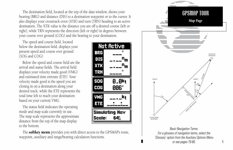
The destination field, located at the top of the data window, shows yourbearing (BRG) and distance (DIS) to a destination waypoint or to the cursor. Italso displays your crosstrack error (XTK) and turn (TRN) heading to an activedestination. The XTK value is the distance you are off a desired course (left orright), while TRN represents the direction (left or right) in degrees betweenyour course over ground (COG) and the bearing to your destination.
The speed and course field, locatedbelow the destination field, displays yourpresent speed and course over ground(SOG and COG).
Below the speed and course field are thearrival and status fields. The arrival fielddisplays your velocity made good (VMG)and estimated time enroute (ETE). Yourvelocity made good is the speed you areclosing in on a destination along yourdesired track, while the ETE represents thetotal time left to reach your destinationbased on your current VMG.
The status field indicates the operatingmode and map scale currently in use. The map scale represents the approximatedistance from the top of the map display to the bottom.
The softkey menu provides you with direct access to the GPSMAP’s route,waypoint, auxiliary and range/bearing calculation functions.
5
Basic Navigation Terms:For a glossary of navigation terms, select the
‘Glossary’ option from the Auxiliary Options Menuor see pages 79-80.
GPSMAP TOURMap Page
NORTH
ACTIVE FROMWAYPOINT
NORTH
DTK
CROSSTRACK ERROR
XTK
BRG
COG
SPEED OVER G
ROUND
DIS
TAN
CE
ACTIVE TOWAYPOINT
215225manb.qxd 4/27/00 9:22 AM Page 5

As you move the cursor, the distance andbearing from your present position to the cursor will be displayed in the destinationfield (at the top right of the screen).
The cursor’s position coordinates will be dis-played in the position field (below the speedand course field).
While in cursor mode, the boat icon will continue to move, and may go off screen toaccommodate the scrolling cursor.
6
Using the Map Page is a simple process that centers around the use of thecursor. Controlled by the arrow keypad, the cursor is an important tool thatcan be used as a distance and bearing marker, to create new waypoints androutes, and to review position data of on-screen waypoints, buoys and markers. Try moving the cursor using the following exercise:
1. Use the L key to set the map scale to 64 n.m.
2. Your boat should be in the center of the map display, near Andros Island andNassau (the position you entered earlier).
3. Press the bottom arrow of the K keypad to move the cursor down to the firstlat/lon grid South of your boat’s position.
4. Using the K keypad to move the target crosshair in each direction, try follow-ing the outline of the lat/lon grid closest to your boat. Notice how the destination field of the data window displays the distance and bearing fromyour position to the target cursor, with the cursor’s coordinate position indicated in the position field.
5. Press the A key to eliminate the cursor and re-center your position on themap display.
As you become more familiar with using the cursor, you’ll see that the mapdisplay actively scrolls forward with your panning, letting you explore areasaround the world (even outside of your current G-chartTM coverage) and createwaypoints and routes. Wherever you move the cursor, you’ll always be oneA keystroke away from returning to your present position.
GPSMAP TOURUsing the Target Cursor
215225manb.qxd 4/27/00 9:22 AM Page 6

The GPSMAP system stores over 1900alphanumeric waypoints, with selectablegraphic icons and a user-defined commentfield. If you mark a navaid position thatappears on a G-chart electronic cartridge, the default comment will automatically selectthe navaid text associated with the marker.
7
To continue the tour, let’s mark our simulated present position for reference:
1. Press the F key to capture your present position as a waypoint.
The Mark GPS Position window will appear, with a default three-digit waypoint name and symbol. By pressing the C key, you can confirm thewaypoint with the default name and symbol, but let’s change the name andsymbol to something a little more meaningful:
1. Use the K keypad to move the field highlight to the ‘Wpt’ field and press C.
2. Enter the name ‘DAY1’ with the K keypad, pressing C after each character.
3. After you’ve entered the last letter, press the OK softkey to confirm the name.
4. The field highlight will move to the waypoint symbol field. Press C to beginselection of a new waypoint symbol.
5. Use the K keypad to highlight the fish symbol (on the second line of the window) and press the C key.
6. The field highlight will move to the comment field, where you may enter a 20-character comment (the default comment is the date and time of creation).
7. Press C to begin entry of a comment.
8. Use the K keypad to enter ‘TOUR’ in the comment field, pressing the C keyafter each character.
9. Press the OK softkey to accept your comment.
10. Use the K keypad to highlight the OK field.
11. Press the C key to save your new waypoint.
GPSMAP TOURMarking a Position
215225manb.qxd 4/27/00 9:22 AM Page 7

Whenever the cursor comes in close proximityto an on-screen waypoint or navaid, it will‘snap’ to and highlight its on-screen icon.
Once an on-screen marker has been high-lighted, destination and position informationwill be displayed in the data window.
This feature makes it easy to review waypointpositions right from the map display.
8
Now that you’ve marked a waypoint for your starting position, let’s make aroute to navigate using the ROUTES softkey. (For the purposes of this tour,make sure that the current map scale is still at 64 n.m.)
1. Press the ROUTES softkey to begin creating a route.
2. Use the K keypad to highlight the Route 1 field and press C.
The GPSMAP system can store 20 reversible routes of up to 50 waypoints each.Routes 1-19 are used as storage routes, with Route 0 always serving as the activeroute. Although you may create a route in the Route 0 position, be aware that it willautomatically become the active route upon completion. If you want to save a routecreated in the Route 0 position, be sure to copy it to another storage route, as it willbe overwritten by the next route activation (see Section 8 for more details on routes).
As the GPSMAP returns to the Map Page, you’ll notice several changes. Themap display will now show the cursor as an arrow at your present position,with the prompt field indicating instructions for adding waypoints to yourroute. To select the DAY1 waypoint as your first route waypoint:
1. Press the C key to add the waypoint to the route.
Now add the next waypoint to the route:
1. Use the K keypad to move the arrow cursor as close as possible to the following coordinates: N 24º 27.371’, W 077º 42.407’.
2. Press C to save the waypoint position.
3. Press C to confirm the default waypoint name, symbol and comment.
GPSMAP TOURCreating a Route
I
215225manb.qxd 4/27/00 9:22 AM Page 8

9
Now add the final waypoint to the route:
1. Use the K keypad to move the arrow cursor as close as possible to the following coordinates: N24º21.777’, W077º51.424.
2. Press the C key to save the waypoint position.
3. Press C to confirm the default waypoint name, symbol and comment.
We now have a three waypoint route from our present position to waypoint 002. To activate the route and begin navigation:
1. Press the EXIT softkey to quit the route creation mode.
2. Press the ACTIVTE softkey.
The GPSMAP will return to the Map Page, with your active route (Route 0)shown on the map display and the ‘active to’ waypoint (001) displayed in thedestination field. The speed and course field tells us we’re getting nowherefast, so let’s go to the Highway Page and enter a speed for our simulated trip:
1. Press the I key to display the Highway Page.
The Highway Page provides you with a large, digital display of navigationdata and graphic steering guidance to an active destination via a three-dimen-sional perspective of your course. As you head toward your destination, themiddle of the screen provides visual guidance on a moving “graphic” highway.
Your present position is at the bottom of the highway display. The linedown the middle of the highway represents your desired course. As you navigate toward a waypoint, the highway will actually move—indicating the direction you’re off course. To stay on course, simply steer toward the centerof the highway.
GPSMAP TOURModifying a Route Graphically
Activating a Route
215225manb.qxd 4/27/00 9:22 AM Page 9

The Simulator SOG/COG window lets youspecify the speed and course for the simulatormode. By leaving the COG field value at the default setting, the GPSMAP system willautomatically set a course directly to yourdestination.
If you choose to enter your own course overground, highlight the COG field and enter the desired course. To reset the simulator tosteer a direct course for you, highlight the‘Reset COG to Nav Course’ prompt and press the C key.10
The active destination waypoint is displayed at the top of the screen, withthe ETE (estimated time enroute) and ETA (estimated time of arrival) based onyour present speed and course at the bottom.
The distance and bearing to the first route waypoint, along with your cur-rent speed and course over ground (SOG and COG), are indicated along theright-hand side of the screen. The SOG and COG fields can be changed to display velocity made good (VMG) and turn (TRN). To toggle the speed andcourse displays, press the B key.
Now enter a speed of 60 knots for our simulated trip:
1. Press the SOG/COG softkey to display the Simulator SOG/COG window.
2. Press the C key to begin data entry.
3. Use the K keypad to enter a speed of 60 knots, pressing the C key aftereach character entry.
4. Once you’ve entered your speed, press the EXIT softkey.
By leaving the COG field value at the default setting, the GPSMAP systemwill automatically set a direct course to each route waypoint. If you choose toenter your own course, highlight the COG field and enter the desired course.To reset the simulator to automatically steer a direct course for you, highlightthe ‘Reset COG to Nav Course’ prompt and press the C key.
At the bottom right corner of the highway display is the highway scale. Thehighway scale ranges from ‘1X’ to ‘16X’, and allows you to change the perspective view of the highway to show a larger or smaller area.
1. Press the down arrow on L to decrease the scale and show a smaller area.
2. Press the up arrow on L to increase the scale and show a larger area.
GPSMAP TOURNavigating a Route
215225manb.qxd 4/27/00 9:22 AM Page 10

11
You are now underway toward the first waypoint in your route. Wheneverthere is an active route in use for navigation, the GPSMAP will display routewaypoint and leg information on the Active Route Page. To view the ActiveRoute Page from the Highway Page:
1. Press the I key.
The Active Route Page shows each waypoint of the active route in sequence,along with the desired track, distance and ETE or ETA to each waypoint fromyour present position. As you navigate a route, the waypoint list will automati-cally update to list the next ‘active to’ waypoint first, followed by the remain-ing route waypoints in sequence. From the Active Route Page, you can:
1. Scroll through the entire list of route waypoints using the K key.
2. Review a highlighted waypoint by pressing the C key.
3. Change the ETE field to display ETA by pressing the B key.
Let’s go back to the Map Page to look at our progress:
1. Press the E key.
As you travel along your route, your boat will move across the map display,leaving a track plot of your course. You may have some difficulty differentiat-ing track plots and route legs at the 64 n.m. scale, so try zooming down pastthe built-in database with L to get a good view of the track plot.
Whenever you zoom past the usable range of the current electronic chart, the rangefield will display ‘Ovr Zm’ or ‘No Map’. These warnings indicate that although youmay still have cartography, you should exercise extreme caution using the data. Fora more detailed explanation of Overzoom and No Map modes, see page 20.
Map Display in Overzoom Mode
GPSMAP TOURActive Route Page
I
215225manb.qxd 4/27/00 9:22 AM Page 11

12
As you approach a destination waypoint, an audible alert and on-screenmessage will indicate when you are one minute from your destination. Toacknowledge the message:
1. Press the C key.
Whenever you’re finished navigating a route with the GPSMAP system,you’ll need to clear the Active Route to stop navigation guidance to the lastroute waypoint. To stop navigation of the Active Route:
1. Press the ROUTES softkey.
2. Press the DELETE softkey, followed by C. (Press the EXIT softkey to return tothe previous page.)
Although creating and navigating routes in the GPSMAP system is a simpleprocess, there may be times when you want to head right to a specific destination without creating a route. Imagine that as you were navigating thecurrent route, you see a spot of interest off the starboard bow. By marking anew position with the cursor and using the GOTO function, we can set a newcourse right from the map display:
1. Use the K keypad to move the cursor as close to the following position aspossible: N 24º 30.000, W 077º 30.000.
2. Press the D key.
Notice that the cursor has become an arrow pointer, and the prompt fielddisplays instructions for going to the cursor position.
1. Press the C key.
2. The New GOTO Waypoint window will appear, asking you to confirm the way-point name, position and details. Press the C key to confirm the information.
GPSMAP TOURMarking a GOTO Destination
215225manb.qxd 4/27/00 9:22 AM Page 12

13
The GPSMAP will now provide you with steering guidance to your new waypoint. To stop navigation to a GOTO destination, clear the active GOTO:
1. Press the D key.
2. Press the CLR GOTO softkey. (Note that in simulator mode, navigation will continue along the previously defined course over ground.)
Congratulations! You’ve now gone through the basic operation of theGARMIN GPSMAP system. Your new unit is a powerful navigation device with many advanced features not covered in the tour.
Now that you have a working knowledge of the unit, use the reference sectionof this manual to help you with advanced navigation and setup functions. Thereference section is organized by topic, so you can quickly find instructions forperforming specific functions, including the installation and use of G-chartTM
electronic navigation charts.
To turn your GPSMAP off:
1. Press and hold the left side of the J key for three seconds.
Thank you for choosing the GARMIN GPSMAP Navigation System. We hope it will be a useful navigation tool for you wherever you may travel. If you have any questions or comments about its use, please call our ProductSupport staff at 913-397-8200. You may also FAX our Product Support staff at 913-397-8282.
Press CLR GOTO to stop navigation.
GPSMAP TOURPower Off
215225manb.qxd 4/27/00 9:22 AM Page 13

REFERENCE SECTION1 – SATELLITE STATUS PAGE
2 – MAP PAGE
3 – HIGHWAY PAGE
4 – ACTIVE ROUTE PAGE
5 – WAYPOINTS
6 – MARK KEY
7 – GOTO/MOB
8 – ROUTES
9 – AUXILIARY MENU
10 – G-CHART CARTRIDGES
14
215225manb.qxd 4/27/00 9:22 AM Page 14

In this example, satellites 5, 21, 23, 25 and 29 arecurrently being tracked, with the corresponding signal strength bars indicating the relative strengthof the signals. Satellites 3, 9, 15, 30 and 31 (shownwith numbers highlighted) are visible, but are notcurrently being tracked. Satellite 8 is being received(as indicated by a hollow bar), but the data is notyet available for use in determining your position.
NOTE: For first time operation, GPSMAP 215 and225 units may require 5 minutes to collect initialsatellite almanac data and establish a present position. You may speed up the initial acquisitionprocess by entering an initial position (see page 16). 15
The GPSMAP 215/225 Satellite Status Page provides a visual reference ofvarious receiver functions, including current satellite coverage, receiver operating mode and present position or DGPS status. The status informationwill give you an idea of what the receiver is doing at any given moment.
The sky view and signal strength bars give you an indication of what satellites are visible to the receiver and whether or not they are being tracked.The signal strength is shown on a bar graph for each satellite, with the satellitenumber below. When a satellite is visible but not being tracked, the strengthbar will remain blank and the sky view indicator will remain highlighted.
The sky view shows a bird’s eye view of the position of each satellite relative to the receiver’s last known position. The outer circle represents the horizon(North up); the inner circle 45º above the horizon; and the center point a position directly overhead. Use the sky view to determine if there are obstructions shading your reception of GPS signals.
SECTION
1Position
Field(or Beacon
Status)
SatelliteSky
View
Status Field
SignalStrength
Indicators
SATELLITE STATUS PAGE
Overview
215225manb.qxd 4/27/00 9:22 AM Page 15
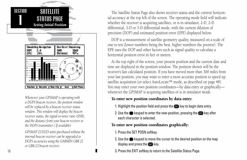
Whenever your GPSMAP is operating with a DGPS beacon receiver, the position windowwill be replaced by a beacon receiver statuswindow. This window will display the beaconreceiver status, the signal-to-noise ratio (SNR),and the distance from your beacon receiver tothe DGPS transmitter.( If available)
GPSMAP 215/225 units purchased without theinternal beacon receiver can be upgraded toDGPS accuracies using the GARMIN GBR 21or GBR 23 beacon receiver.
16
The Satellite Status Page also shows receiver status and the current horizon-tal accuracy at the top left of the screen. The operating mode field will indicatewhether the receiver is acquiring satellites, or is in simulator, 2-D, 2-D differential, 3-D or 3-D differential mode; with the current dilution of precision (DOP) and estimated position error (EPE) displayed below.
DOP is a measurement of satellite geometry quality, measured on a scale ofone to ten (lower numbers being the best, higher numbers the poorest). TheEPE uses the DOP and other factors such as signal quality to calculate a horizontal position error in feet or meters.
At the top right of the screen, your present position and the current date andtime are displayed in the position window. The position shown will be thereceiver’s last calculated position. If you have moved more than 300 miles fromyour last position, you may want to enter a more accurate position to speed upsatellite acquisition (or select AutoLocate™ mode, as described on page 48).You may enter your own position coordinates—by data entry or graphically—whenever the GPSMAP is acquiring satellites or is in simulator mode.
To enter new position coordinates by data entry:
1. Highlight the position field and press the C key to begin data entry.
2. Use the K keypad to enter the new position, pressing the C key after each character is selected.
To enter new position coordinates graphically:
1. Press the SET POSN softkey.
2. Use the K keypad to move the cursor to the desired position on the map display and press the C key.
3. Press the EXIT softkey to return to the Satellite Status Page.
SECTION
1SATELLITE
STATUS PAGESetting Initial Position
215225manb.qxd 4/27/00 9:22 AM Page 16

The GPSMAP Map Page provides a comprehensive display of electronic cartography, plotting and navigational data. It is the primary page used fornavigating with the GPSMAP system. The Map Page can be broken down into three main sections: map display, data window and softkey menu.
The map display shows your boat on an electronically generated chart,complete with geographic names, navaids, depth contours and a host of otherchart features. It also plots your track and displays any routes and waypointsyou create. An on-screen cursor lets you pan and scroll to other map areas,determine the distance and bearing to a position, and perform various routeand waypoint functions. The GPSMAP system has a built-in worldwide database to 64 n.m. (see Appendix F for built-in coverage map), with moredetailed coverage available through the use of G-chartTM data cartridges (seeSection 10 for installing and using G-chartTM cartridges).
Your boat’s position is represented by a wedge icon, with your track plot shown as a dottedline (GPSMAP215) or a solid yellow line(GPSMAP225).
To select what chart features are displayed on a particular chart scale, refer to the MapConfiguration section on pages 23-24.
17
SECTION
2Data
Window
Map Display
SoftkeyMenu
Boat Icon
DestinationFields
MAP PAGEOverview
215225manb.qxd 4/27/00 9:22 AM Page 17

18
The map display uses the cursor keypad and a set of hard keys to controlmost map display functions. The L, A, C and E keys, combinedwith the K keypad lets you select zoom ranges, move the cursor and displaychart outlines. Two basic map operating modes determine what cartography isshown on the map display: boat mode and cursor mode. Boat mode pans thecartography to keep the present position marker within the display area, whilecursor mode pans the cartography to keep the cursor within the display area.
The GPSMAP system will always power up in the boat mode, with your vessel centered on the map display. In boat navigation mode:
• Your movement is shown by the map scrolling past the centered boat.
• Whenever sufficient map coverage is not available to keep the boat centered,the boat icon will move toward the edge of the display.
• If the boat icon attempts to go off the display, the zoom level may need to beadjusted to keep cartography on screen.
Whenever the K keypad is pressed, the GPSMAP will enter cursor mode.In cursor mode:
• The cursor can be moved over the map display using the K keypad.
• Whenever the cursor reaches the edge of the display, the map will scroll forward under the cursor. Keep in mind that the boat icon will move with themap scrolling, and may go off the display screen (you may not be able to seeyour present position).
• When the cursor is stationary, a fixed coordinate position will appear in theposition field. Note that the distance and bearing, displayed in the destinationfield, will change as your boat’s position changes.
• Whenever you zoom in cursor mode, the cursor will be centered on screen.
SECTION
2
Boat Mode
Cursor Mode
MAP PAGEMap Page Modes
215225manb.qxd 4/27/00 9:22 AM Page 18

19
The cursor allows you to pan away from your present position and scroll to other map areas around the world (even outside of your current G-chartTM
coverage). As you pan past the edge of the current map display, the screen will actively scroll forward to provide continuous map coverage wherever you move the cursor.
To move the cursor:
1. Press the appropriate arrow icon on the K keypad to move the cursor in thedesired direction.
As you move the cursor, the distance and bearing from your present position to the cursor, will be displayed in the data window, with the cursor’sposition coordinates shown in the position field. Keep in mind that when thecursor is stationary, the distance and bearing from your present position willchange as your boat moves.
The cursor may also be used to ‘snap’ to on-screen waypoints and navaids,allowing you to review the selected position directly from the map display
To select an on-screen waypoint or navaid with the cursor:
1. Use the K keypad to move the cursor to the desired waypoint or navaid. (If there are several waypoints grouped closely together, zoom in closer for a better view of the area.)
2. When a waypoint or navaid is selected, it will become highlighted on-screen,with the name, position, comment and icon displayed in the data window.
To eliminate the cursor, re-center your position on-screen and returnto the boat navigation mode:
1. Press the A key.
SECTION
2
Snapping to an on-screen waypoint
Remove the cursor by pressing the A key
MAP PAGEUsing the Cursor
215225manb.qxd 4/27/00 9:22 AM Page 19

20
The map display has 16 available range scales from 1/8th to 4096 n.m. (1/4to 7500km). The map scale is controlled by the L key, with the currentscale displayed at the bottom of the data window.
To select a map scale:
1. Press the arrow icon on the right or left side of the L key to zoom in or out.
The GPSMAP will display cartography as long as there is chart informationavailable for the range you’ve selected. Zooming operation will conform to thefollowing default settings:
• When the selected zoom range is covered by either the internal database or aG-chartTM data cartridge, cartography will be displayed.
• When the selected zoom range is covered by both the internal database and a G-chartTM cartridge, cartography will be displayed using the data with the best resolution.
• When the selected zoom range exceeds the resolution of the chart in use by up to two settings, OVERZOOM cartography will be displayed. The display will not show any filled landmass areas, and an ‘Ovr Zm’ warning will appear in the scale field and the lat/lon grid will be turned on regardless of the mapconfiguration setting. Although OVERZOOM cartography provides some level of map detail, additional caution should be used while navigating.
• When the selected zoom range exceeds the resolution of the chart in use bymore than two settings, a ‘No Map’ warning will appear and all cartography willbe replaced by a TRACK PLOT display. The lat/lon grid will be displayed regard-less of the map configuration setting. Additional caution should be used whilenavigating in track plot mode.
SECTION
2
Overzoom Mode
Track Plot Mode
MAP PAGESelecting Zoom Scales
215225manb.qxd 4/27/00 9:22 AM Page 20

21
The second section of the Map Page is the data window, located at the rightside of the screen display. The data window provides a digital display of navigation data in relation to your present position, the cursor position or a particular waypoint.
The top area of the data window includes the destination fields, which display the bearing and distance to the destination waypoint indicated, withcrosstrack error (XTK) and turn value (TRN) shown at the bottom. If there isnot an active destination waypoint, ‘Not Active’ will be indicated above thedestination fields. The XTK value is the distance you are off a desired course,while TRN represents the direction in degrees between your course overground (COG) and the bearing to your destination. Whenever the cursor is inuse, the destination field will display the distance and bearing from your present position to the cursor.
The speed and course fields, located below the destination fields, displayyour present speed and course over ground (SOG and COG). Directly belowthese fields are the arrival and status fields. The arrival fields display yourvelocity made good (VMG) and estimated time enroute (ETE). VMG is thespeed you are closing in on a destination along the desired track, with the ETErepresenting the total time left to your destination based on your currentVMG. Whenever the cursor is in use, the arrival fields will be replaced by aposition field, which displays the coordinates of the cursor.
The status field, located directly below the arrival field, indicates the operating mode and map scale currently in use. When the cursor is used to‘snap’ to an on-screen waypoint or navaid, the arrival and status fields will bereplaced with a waypoint review field, showing the name, position, icon andcomment for the selected on-screen position.
SECTION
2
Destination Fields
Speed & CourseFields
Arrival Fields
StatusField
MAP PAGEData Window
215225manb.qxd 4/27/00 9:22 AM Page 21

The last section of the Map Page is the softkey menu, which is displayedacross the bottom of the screen. The first two softkeys provide quick access toroute and waypoint functions from any GPSMAP page. The AUX softkey provides instant access to the Auxiliary Menu. For instructions on using thesesoftkeys, refer to the section dedicated to each key. The RNG/BRG softkeyappears only on the Map Page, and lets you use the cursor to calculate therange and bearing between any two on-screen positions.
To calculate the distance and bearing between two points:
1. Press the RNG/BRG softkey.
2. Use the K keypad to move the arrow cursor to the desired reference positionand press the C key. To clear a reference point, press the CLEAR softkey.
3. Use the K keypad to move the arrow cursor to the desired finish position. The bearing and distance from the reference point will be displayed in the destination window.
4. Press the EXIT softkey to quit the RNG/BRG mode.
Although the Map Page’s data window/softkeys provide you with importantdata and system functions, you may prefer to have a full-screen map display.To display cartography on the entire page, simply ‘turn off’ the other displays.
To turn the data window display on or off:
1. Press the B key.
To turn the softkey menu display on or off:
1. Press the G key.22
SECTION
2
Calculating Range/Bearing
Expanded Map Display
MAP PAGERange & Bearing
Softkey Menu
215225manb.qxd 4/27/00 9:22 AM Page 22

23
The GARMIN GPSMAP system features a graphic map display with 16 zoomscales from 1/8th to 4096 n.m. (1/4 to 7500km). By using G-chartTM inlandand offshore chart cartridges, the map display can show a wide variety of chartdetails such as depth contours, shorelines, marinas and navigation aids.
The MAP CFG softkey allows you to determine what chart features are dis-played on a particular range scale. By selecting individual features on the mapconfiguration windows, you can choose what specific information to display.
To access the map display configuration windows:
1. Press the MAP CFG softkey.
The configuration windows feature an on/off grid with a list of chart featuresdown the left side of the grid. The zoom scales are displayed across the top ofthe grid, with the chart scale currently in use indicated by a box outlinearound the selection grid The far left column denotes range scales 64 n.m.(120 km) and greater. A check mark in a grid box indicates that the chart fea-ture listed will be displayed at the scale marked at the top of the grid. A con-figuration grid is available for Marine and Land data.
To select a configuration window for Marine or Land data:
1. Press the MARINE or LAND softkey (as appropriate).
Individual grid boxes are turned on and off with the C key, while entirerows may be controlled by using the configuration softkeys.
To use the map configuration grid:
1. Use the K key to toggle an individual grid box on or off.
2. Press the DEFAULTS softkey to return the entire grid to the factory settings.
3. Use the SET ROW softkey to turn an entire horizontal row on.
4. Use the CLR ROW softkey to turn an entire horizontal row off.
SECTION
2MAP CONFIGURATION
Selecting On-ScreenDisplay Features
Marine Data Configuration
Land Data Configuration
215225manb.qxd 4/27/00 9:22 AM Page 23

Note that geographic names and navaid text can’t be displayed simultane-ously at range scales greater than 2 n.m. (4 km) and that navaid text is alwaysavailable in the review window by highlighting the navaid with the cursor.Waypoint names and lat/lon labels cannot be displayed unless the waypointsor lat/lon grid options have been selected. The lat/lon grid will always appearin Overzoom and No Map modes, regardless of the configuration selection.
The map display configuration windows also feature a map calibration soft-key to provide access to a user-defined map correction function. This functionallows you to calibrate the map display to match your exact physical position(see left for Selective Availability warning) or correct data from older charts.
If your GPSMAP is not providing an accurate display of your position (within the estimated position error noted on the Satellite Status Page), check to seethat your GPSMAP map datum matches the datum on the chart(s) you areusing (see Section 9 for selecting a map datum). To calibrate the map display,you must know exactly where you are, and understand that the correction isgenerally valid only in a limited range from the point of correction. Youshould also only perform a map calibration when your boat is not moving.The maximum correction is 16,400 feet (5000m). Note that all map calibrationoffsets will stay in effect until they are cancelled!
To perform a map calibration from the map configuration window:
1. Press the MAP CAL softkey.
2. Use the K key to move the arrow cursor from the satellite position (indicatedby the satellite icon) to your exact position. The bearing, distance, and horizon-tal and vertical offset will be indicated at the top of the data window, with theposition coordinates indicated in the position field.
3. Press C to confirm the offset, and EXIT to return to the configuration window.
4. To cancel a map calibration offset, press the MAP CAL softkey. When the mapdisplay appears, press the CLEAR softkey, followed by the EXIT softkey.
WARNING!The map calibration function is valid only ina limited range. The further you are awayfrom the point of correction, the larger theposition error will be. Keep in mind thatSelective Availability can cause positionerrors up to 330 feet (100 m).
The map calibration function should NEVERbe used to attempt SA corrections. Any incor-rect use of the calibration function can seri-ously affect the accuracy of your unit.
24
SECTION
2MAP CONFIGURATION
Map Calibrations
215225manb.qxd 4/27/00 9:22 AM Page 24
25
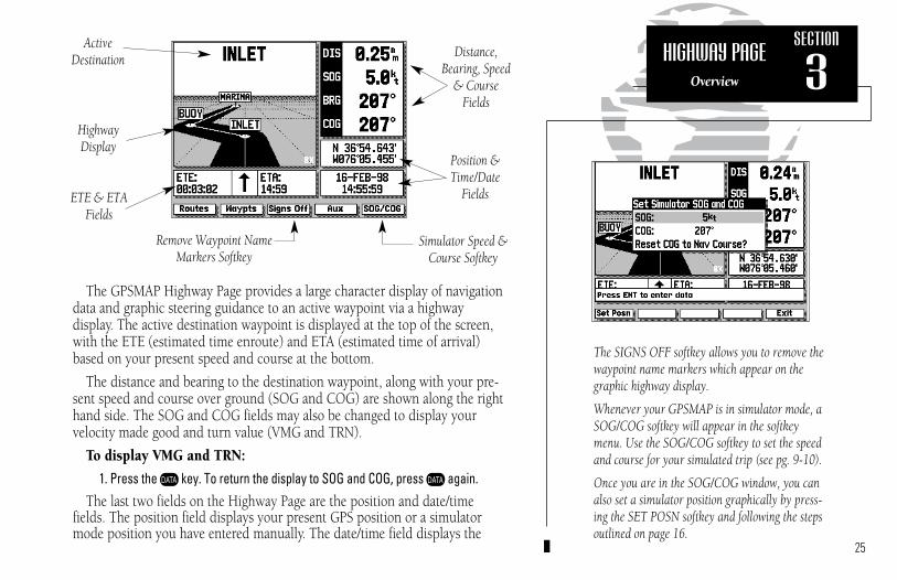
The GPSMAP Highway Page provides a large character display of navigationdata and graphic steering guidance to an active waypoint via a highway display. The active destination waypoint is displayed at the top of the screen,with the ETE (estimated time enroute) and ETA (estimated time of arrival)based on your present speed and course at the bottom.
The distance and bearing to the destination waypoint, along with your pre-sent speed and course over ground (SOG and COG) are shown along the righthand side. The SOG and COG fields may also be changed to display yourvelocity made good and turn value (VMG and TRN).
To display VMG and TRN:
1. Press the B key. To return the display to SOG and COG, press B again.The last two fields on the Highway Page are the position and date/time
fields. The position field displays your present GPS position or a simulatormode position you have entered manually. The date/time field displays the
The SIGNS OFF softkey allows you to remove thewaypoint name markers which appear on thegraphic highway display.
Whenever your GPSMAP is in simulator mode, aSOG/COG softkey will appear in the softkeymenu. Use the SOG/COG softkey to set the speedand course for your simulated trip (see pg. 9-10).
Once you are in the SOG/COG window, you canalso set a simulator position graphically by press-ing the SET POSN softkey and following the stepsoutlined on page 16.
SECTION
3Distance,
Bearing, Speed& Course
Fields
Position &Time/Date
Fields
ActiveDestination
HighwayDisplay
ETE & ETA Fields
Simulator Speed & Course Softkey
HIGHWAY PAGEOverview
Remove Waypoint NameMarkers Softkey
215225manb.qxd 4/27/00 9:22 AM Page 25

current date and time as calculated from GPS satellites. The date and time for-mats may be changed through the system setup softkey (see Section 9), andthe time may be set to display either UTC (Greenwich Mean Time) time or thelocal time, based on a local offset entered in the system setup menu.
The Highway Page’s graphic highway display occupies the majority of thescreen, starting at the upper left corner.
The highway display provides visual guidance to the destination waypointand keeps you on your intended course line. Your course is represented by thecenter line down the middle of the graphic highway. As you head toward yourdestination, the highway perspective will change to indicate your progress tothe waypoint and which direction you should steer to stay on course. If thehighway moves off to one side, simply steer toward the highway to return tocourse. When navigating a route, the highway display will show each routewaypoint in sequence. Nearby waypoints not in the route will also be dis-played. You can zoom in or out on the highway display (through five availablesettings) for a smaller or larger view.
To zoom in or out on the highway display:
1. Press the down arrow on L to show a smaller view area.2. Press the up arrow on L to show a larger view area.
The bearing pointer, directly below the high-way display, always points to the destinationwaypoint (or the next waypoint when using aroute) relative to your course over ground(COG). If the bearing pointer points straightahead, you are heading directly to your destination. If the bearing pointer points anydirection other than up, turn toward thearrow until it points up—then continue inthat direction.
26
SECTION
3Current and Final
DestinationWaypoints
Highway Scale
Desired Course(highway centerline)
Nearby RouteWaypoint
HIGHWAY PAGEHighway Display
& Scale
215225manb.qxd 4/27/00 9:22 AM Page 26
27
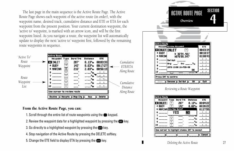
The last page in the main sequence is the Active Route Page. The ActiveRoute Page shows each waypoint of the active route (in order), with the waypoint name, desired track, cumulative distance and ETE or ETA for eachwaypoint from the present position. Your current destination waypoint, the‘active to’ waypoint, is marked with an arrow icon, and will be the first waypoint listed. As you navigate a route, the waypoint list will automaticallyupdate to display the next ‘active to’ waypoint first, followed by the remainingroute waypoints in sequence.
From the Active Route Page, you can:
1. Scroll through the entire list of route waypoints using the K keypad.
2. Review the waypoint data for a highlighted waypoint by pressing the C key.
3. Go directly to a highlighted waypoint by pressing the D key.
4. Stop navigation of the Active Route by pressing the DELETE softkey.
5. Change the ETE field to display ETA by pressing the B key.
SECTION
4
RouteWaypoint
List
CumulativeETE/ETA
Along Route
CumulativeDistance
Along Route
‘Active To’Route
Waypoint
Reviewing a Route Waypoint
Deleting the Active Route
ACTIVE ROUTE PAGEOverview
215225manb.qxd 4/27/00 9:22 AM Page 27

28
The GARMIN GPSMAP system stores over 1900 alphanumeric waypointswith a user-defined icon and comment available for each waypoint. Waypointscan be created, reviewed, moved or deleted right from the Map Page using thetarget cursor to select positions and waypoints, and are managed through theWAYPOINTS softkey. Once you are in the waypoint mode, you can also create,edit and review waypoints through the waypoints list and the nearest waypoints windows. Let’s cover the graphic waypoint functions first.
To create a waypoint from the map display:
1. Press the WAYPTS softkey. The target cursor will appear as an arrow pointer.
2. Use the K keypad to move the arrow cursor to the desired waypoint position.
3. Press the C key to capture the position.
The New Waypoint window will appear, with a default three-digit name andgraphic icon. The position coordinates are displayed in the center of the window, with a user-defined comment field below.
4. To accept the default waypoint name, icon and comment (the date and time ofcreation), press the C key to confirm the ‘OK’ prompt.
The GPSMAP system lets you enter your own six character waypoint name,a 20-character user comment and a graphic icon for each waypoint.
To enter a user-defined name, icon or comment:
1. Highlight the name, icon or comment field and press C.
2. Use the K keypad to enter a name, icon or comment and press the OK softkey (for name and comment entry) or the C key (for icon selection).
3. After you’ve made your changes, highlight the OK prompt and press C.
SECTION
5WAYPOINTS
Creating WaypointsGraphically
215225manb.qxd 4/27/00 9:22 AM Page 28

29
Other graphic waypoint functions include reviewing and modifying on-screen waypoints. By moving the cursor close to an on-screen waypoint,you can “snap” to a specific waypoint. Once the target cursor snaps to a waypoint, the waypoint will be highlighted with a white circle, and theGPSMAP will display waypoint information in the data window at the bottomright corner of the screen. When an on-screen waypoint is highlighted, you’llbe able to review, edit, move or delete the waypoint.
To select and review an on-screen waypoint:
1. Use the K keypad to ‘snap to’ the on-screen waypoint.
2. Press C to display the Review Waypoint window for the highlighted waypoint.
From the Waypoint Review window, you can change the waypoint name,icon or comment, edit the position coordinates, or delete the waypoint. Youcan also determine the distance and bearing from the displayed waypoint toany other waypoint stored in your GPSMAP system.
To change the waypoint icon, comment or position:
1. Highlight the icon, comment, or position field and press C.
2. Use the K keypad to enter the new icon, comment or position and press theOK softkey (for name and comment entry) or the C key (for icon selection).
3. After you’ve made your changes, highlight the ‘OK’ prompt and press C.
To change the waypoint name or delete the waypoint from memory:
1. To rename the waypoint, press the RENAME softkey, use the K keypad toenter the new waypoint name, and press the OK softkey when finished.
2. To delete the waypoint, press the DEL WPT softkey and C to confirm.
Note:‘Active to’ destination waypoints cannot bedeleted from system memory until the activeGOTO or route has been cancelled.
To cancel an active GOTO, press the Dkey, then press the CLR GOTO softkey.
To cancel an active route, press the ROUTES softkey, highlight route 0, then press the DELETE softkey.
SECTION
5WAYPOINTS
Reviewing & Editing Waypoints Graphically
Data for the selected waypoint or navaid isdisplayed at the bottom right corner of screen.
215225manb.qxd 4/27/00 9:22 AM Page 29
30
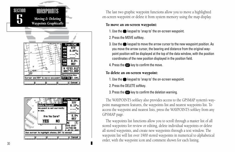
The last two graphic waypoint functions allow you to move a highlightedon-screen waypoint or delete it from system memory using the map display.
To move an on-screen waypoint:
1. Use the K keypad to ‘snap to’ the on-screen waypoint.
2. Press the MOVE softkey.
3. Use the K keypad to move the arrow cursor to the new waypoint position. Asyou move the arrow cursor, the bearing and distance from the original way-point position will be displayed at the top of the data window, with the positioncoordinates of the new position displayed in the position field.
4. Press the C key to confirm the move.
To delete an on-screen waypoint:
1. Use the K keypad to ‘snap to’ the on-screen waypoint.
2. Press the DELETE softkey.
3. Press the C key to confirm the deletion warning.
The WAYPOINTS softkey also provides access to the GPSMAP system’s way-point management features, the waypoints list and nearest waypoints list. Toaccess the waypoint and nearest lists, press the WAYPOINTS softkey from anyGPSMAP page.
The waypoints list functions allow you to scroll through a master list of allstored waypoints for review or editing, delete individual waypoints or deleteall stored waypoints, and create new waypoints through a text window. Thewaypoint list will list over 1900 stored waypoints in numerical to alphabeticalorder, with the waypoint icon and comment shown for each listing.
SECTION
5WAYPOINTS
Moving & DeletingWaypoints Graphically
215225manb.qxd 4/27/00 9:22 AM Page 30

31
To scroll through and review the waypoint list:
1. Press the WAYPTS softkey (if you are not currently in the waypoints submenu).
2. Press the LIST softkey.
3. Use the K keypad to scroll through the list in either direction.
4. Press the C key to review the highlighted waypoint.
5. Highlight the OK prompt and press C to return to the waypoint list.
6. The field highlight will automatically scroll to the next waypoint. If you want tosee the review waypoint window for each listing, you can also scroll throughany waypoint list by pressing the C key repeatedly.
Once the waypoint review window is displayed, you may change any datafield, rename or delete the waypoint by following the steps outlined on page29. You can also delete an individual waypoint or the entire list of waypointsright from the waypoint list.
To delete an individual waypoint from the list:
1. Use the K keypad to highlight the waypoint to be deleted.
2. Press the DELETE softkey.
3. Press the C key to confirm the deletion warning.
To delete the entire list of waypoints:
1. Press the DEL ALL softkey.
2. Press the K keypad to highlight the ‘YES’ prompt.
3. Press the C key to confirm the deletion.
Once a waypoint on the waypoint list is highlighted, you can select it as a GOTO destination right from the list by pressing theD key, followed by C.
SECTION
5WAYPOINTS
Using the Waypoints List
215225manb.qxd 4/27/00 9:22 AM Page 31

32
The CREATE softkey lets you create new waypoints by entering a name andposition, or by entering the distance and bearing from an existing (reference)waypoint.
To create a new waypoint from the list submenu:
1. If the waypoints list isn’t currently displayed, select it by pressing the WAYPTSsoftkey, followed by the LIST softkey.
2. Press the CREATE softkey.
3. Use the K keypad to enter the new waypoint name.
4. Press the OK softkey to confirm the name.
5. The Create a New Waypoint window will appear, with the icon field highlighted. To select an icon for your waypoint, press C and use the Kkeypad to choose the icon. Press the C key to confirm the selection.
6. To enter the position coordinates of the new waypoint, highlight the positionfield and press C. Use the K keypad to enter the position, and press C toconfirm the entry.
7. To accept the new waypoint with the default comment (the date and time ofcreation), press C. To enter your own comment, highlight the comment fieldand press the C key. Use the K keypad to enter the comment and press theOK softkey to confirm your entry.
8. When you have finished entering all your waypoint data, use the K keypad tohighlight the OK prompt and press the C key.
If you don’t know the position coordinates for your new waypoint, you canenter the distance and bearing from a reference waypoint (any waypoint storedin memory), and the GPSMAP will calculate the coordinates for you.
SECTION
5WAYPOINTS
Creating Waypoints by Text Entry
215225manb.qxd 4/27/00 9:22 AM Page 32
33
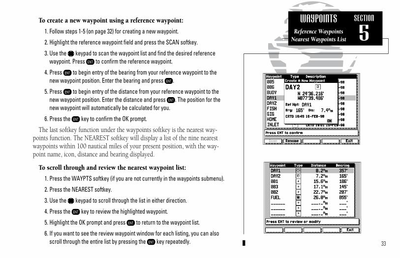
To create a new waypoint using a reference waypoint:
1. Follow steps 1-5 (on page 32) for creating a new waypoint.
2. Highlight the reference waypoint field and press the SCAN softkey.
3. Use the K keypad to scan the waypoint list and find the desired referencewaypoint. Press C to confirm the reference waypoint.
4. Press C to begin entry of the bearing from your reference waypoint to thenew waypoint position. Enter the bearing and press C.
5. Press C to begin entry of the distance from your reference waypoint to thenew waypoint position. Enter the distance and press C. The position for thenew waypoint will automatically be calculated for you.
6. Press the C key to confirm the OK prompt.
The last softkey function under the waypoints softkey is the nearest way-points function. The NEAREST softkey will display a list of the nine nearestwaypoints within 100 nautical miles of your present position, with the way-point name, icon, distance and bearing displayed.
To scroll through and review the nearest waypoint list:
1. Press the WAYPTS softkey (if you are not currently in the waypoints submenu).
2. Press the NEAREST softkey.
3. Use the K keypad to scroll through the list in either direction.
4. Press the C key to review the highlighted waypoint.
5. Highlight the OK prompt and press C to return to the waypoint list.
6. If you want to see the review waypoint window for each listing, you can alsoscroll through the entire list by pressing the C key repeatedly.
SECTION
5WAYPOINTS
Reference WaypointsNearest Waypoints List
215225manb.qxd 4/27/00 9:22 AM Page 33

The GARMIN GPSMAP system features a F key that lets you quickly capture your present position or a target cursor position and create a newwaypoint right from the map display. The F key will capture your presentposition when the cursor is not in use, or will give you the option of markingyour present position or the cursor position when the cursor is in use.
To mark your present position:
1. Press the F key to capture your present position.
2. If you want to accept the waypoint with the default name, symbol and comment, press C to confirm the ‘OK’ prompt.
3. To enter your own name, symbol or comment, highlight the appropriate fieldand press C.
4. After entering your changes, using the K keypad, move the field highlightback to the ‘OK’ prompt and press C.
To mark the cursor position:
1. Use the K keypad to move the cursor to the desired position.
2. Press the F key to mark the position.
3. Press the CURSOR softkey to use the Cursor Position.
4. If you want to accept the waypoint with the default name, symbol and comment, press C to confirm the ‘OK’ prompt.
5. After entering your changes, using the K keypad, move the field highlightback to the ‘OK’ prompt and press C.
The cursor may also be used to mark a navaid position as a waypoint bypointing to the desired navaid with the cursor, following the steps above, andselecting the NAVAID softkey (in lieu of the CURSOR softkey). The defaultcomment will be the navaid text shown on the Map Page.34
SECTION
6MARK KEY
Marking GPS & Cursor Positions
215225manb.qxd 4/27/00 9:22 AM Page 34
35
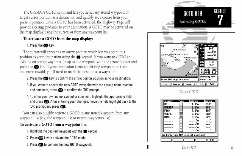
The GPSMAP’s GOTO command lets you select any stored waypoint or target cursor position as a destination and quickly set a course from your present position. Once a GOTO has been activated, the Highway Page willprovide steering guidance to your destination. A GOTO may be activated onthe map display using the cursor, or from any waypoint list.
To activate a GOTO from the map display:
1. Press the D key.
The cursor will appear as an arrow pointer, which lets you point to a position as your destination using the K keypad. If you want to GOTO anexisting on-screen waypoint, ‘snap to’ the waypoint with the arrow pointer andpress the C key. If your destination is not an existing waypoint or is an on-screen navaid, you’ll need to mark the position as a waypoint:
2. Press the C key to confirm the arrow pointer position as your destination.
3. If you want to accept the new GOTO waypoint with the default name, symboland comment, press C to confirm the ‘OK’ prompt.
4. To enter your own name, symbol or comment, highlight the appropriate fieldand press C. After entering your changes, move the field highlight back to the‘OK’ prompt and press C.
You can also quickly activate a GOTO to any stored waypoint from any waypoint list (e.g. the waypoint list or nearest waypoints list).
To activate a GOTO from a waypoint list:
1. Highlight the desired waypoint with the K keypad.
2. Press D key to activate the GOTO mode.
3. Press C to confirm the new GOTO waypoint.
SECTION
7GOTO KEY
Activating GOTOs
Cursor GOTO
List GOTO
215225manb.qxd 4/27/00 9:22 AM Page 35
36
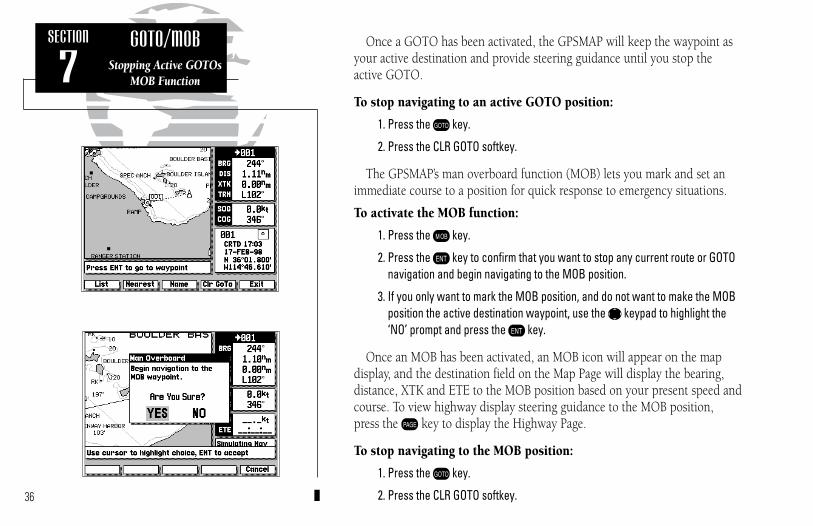
Once a GOTO has been activated, the GPSMAP will keep the waypoint asyour active destination and provide steering guidance until you stop the active GOTO.
To stop navigating to an active GOTO position:
1. Press the D key.
2. Press the CLR GOTO softkey.
The GPSMAP’s man overboard function (MOB) lets you mark and set animmediate course to a position for quick response to emergency situations.
To activate the MOB function:
1. Press the H key.
2. Press the C key to confirm that you want to stop any current route or GOTOnavigation and begin navigating to the MOB position.
3. If you only want to mark the MOB position, and do not want to make the MOBposition the active destination waypoint, use the K keypad to highlight the‘NO’ prompt and press the C key.
Once an MOB has been activated, an MOB icon will appear on the map display, and the destination field on the Map Page will display the bearing, distance, XTK and ETE to the MOB position based on your present speed andcourse. To view highway display steering guidance to the MOB position, press the I key to display the Highway Page.
To stop navigating to the MOB position:
1. Press the D key.
2. Press the CLR GOTO softkey.
SECTION
7GOTO/MOB
Stopping Active GOTOsMOB Function
215225manb.qxd 4/27/00 9:22 AM Page 36

Routes are broken down and navigated insmaller segments called ‘legs’. The waypointyou are going to in a leg is called the ‘activeto’ waypoint, and the waypoint immediatelybehind you is called the ‘active from’ waypoint. The line connecting the ‘active to’and ‘active from’ waypoint is referred to asthe ‘active leg’.
When a route is activated in the GPSMAPsystem, the route leg closest to your position isautomatically selected as the ‘active leg’.
Waypoint 2(“active to” waypoint)
Waypoint 1(“active from” waypoint)
“Active Leg”
«
««
«
ê
37
The GARMIN GPSMAP system lets you create and store up to 20 reversibleroutes with up to 50 waypoints each. Routes can be created and modified rightfrom the Map Page, allowing you to see each route graphically on-screen asyou create, review, modify or navigate the route. The GARMIN route system isa powerful and extremely flexible system that you’ll want to master to get themost out of your GPSMAP system.
Each route in the GPSMAP system has its own route number. Routes 1through 19 are used as storage routes, with Route 0 always serving as theactive route you are navigating. When you activate a route, the storage routeyou are activating is simply copied into Route 0, the active route.
This feature lets you modify your active route while you navigate, withoutchanging the storage route you activated. When you are finished navigatingthe active route, simply delete Route 0 by pressing the DELETE softkey (youstill have the original route in storage) to stop navigating the active route. Tostore a modified Active Route, copy Route 0 to an empty storage route.
SECTION
8ROUTESOverview
When a route is activated or inverted, it is copied into Route 0. The original routeremains intact in its original storage route.
215225manb.qxd 4/27/00 9:22 AM Page 37

38
All of the GPSMAP route functions are accessed through the ROUTES softkey, located at the far left of the softkey menu.
To create a route from the map display:
1. Press the ROUTES softkey to display the route list window.
2. Use the K keypad to select an empty storage route (routes 1-19) and press theC key. You can create a route in the active route (Route 0) position, but you’llneed to copy it to an empty storage route to save it, as it will be overwritten bythe next route activation.
3. The route list window will be replaced by the Map Page, with the target cursorappearing as an arrow pointer. To add waypoints to the route, use the K key-pad to move the arrow cursor to the desired position and press the C key.
HINT: Once the map display is in route creation mode, you can use the arrow cursor to ‘snap to’ existing on-screen waypoints or navaids, or create new waypoint positions. Existing waypoint positions will be added to the route withoutconfirmation. Whenever you are adding a new route waypoint not currentlystored in memory, you’ll be asked to save the new waypoint.
4. Press C to confirm the ‘OK’ prompt.
5. Once you’ve entered all the desired route waypoints, press the EXIT softkey.
The map display will now return to the map review mode, where you can review, activate, invert or modify the current on-screen route. The reviewmode will always appear when you have finished creating a new route on the map display or when you have selected an existing route for review fromthe route list window.
SECTION
8ROUTES
Creating RoutesGraphically
215225manb.qxd 4/27/00 9:22 AM Page 38

39
When the review mode is in use, the cursor may be used to highlight indi-vidual route legs. When a route leg is highlighted, the ‘active from’ and ‘activeto’ waypoints will be displayed at the bottom of the data window, with thedesired track (DTK) and distance (DIS) for the leg indicated below. The rest ofthe map review functions are performed through the map review softkeys atthe bottom of the screen.
To activate or invert the on-screen route:
1. Press the ACTIVATE softkey.
2. To invert (activate in reverse order) the route, press the INVERT softkey.
Once a route has been activated or inverted, the destination field in the datawindow will display navigation information to the next ‘active to waypoint’.As you complete navigation of each route leg, this information will be updatedto reflect the next ‘active to’ waypoint in the route. When you reach the finaldestination waypoint in the active route, you’ll need to cancel the active routeto stop navigation to the last route waypoint. Also note that the Active Route,if not cancelled, will be automatically reactivated when the unit is powered up.
To stop navigation of the active route:
1. Press the ROUTES softkey.
2. Press the DELETE softkey.
3. Press the C key to confirm the delete route warning.
To save a newly created or modified Active Route, copy Route 0 to an openstorage route (Routes 1-19), as the Active Route will be overwritten by anynew route activation.
SECTION
8ROUTES
Map Review ModeActivating & Deleting
Activated Routes appear as solid lines.
215225manb.qxd 4/27/00 9:22 AM Page 39

The next softkey in the route review mode allows you to modify a route bymoving, inserting or removing route waypoints on screen or editing a routethrough a text review window.
To modify the on-screen route:
1. Select the route review mode for the desired route, as described on page 38.
2. Press the MODIFY softkey.
Once you have pressed the MODIFY softkey, you’ll notice that you have anew set of softkeys below the map display:
• The MOVE softkey allows you to move the position of any route waypoint on screen.
• The INSERT softkey will let you add a new route waypoint before thefirst route waypoint, add a new route waypoint after the last route waypoint or add a new waypoint anywhere in between.
• The REMOVE softkey will let you delete any waypoint from the routeand adjusts the route legs accordingly.
• The ENT TEXT softkey provides an editing window to add a comment;review, insert or remove waypoints; or activate/invert the route.
• The EXIT softkey returns you to the route review mode.
To move an on-screen waypoint:
1. Use the K keypad to snap to the waypoint you want to move.
2. Press the MOVE softkey.
3. Use the K keypad to move the arrow cursor to the new waypoint position.
4. Press the C key to complete the move.40
SECTION
8ROUTES
Modifying RoutesMoving Route Waypoints
215225manb.qxd 4/27/00 9:22 AM Page 40

41
The INSERT softkey allows you to add a waypoint before the first routewaypoint or after the last route waypoint; or add a new route waypoint to anexisting route leg.
To insert a new starting or ending route waypoint:
1. Use the K keypad to snap to and highlight the first or last route waypoint.
2. Press the INSERT softkey.
3. Use the K keypad to move the arrow cursor to the new waypoint position.
4. If the new waypoint position is not an existing waypoint, confirm the New RouteWaypoint by highlighting the ‘OK’ prompt and pressing the C key.
5. Press the C key to complete the insertion.
6. Press the EXIT softkey to return to the route modification mode.
To insert a new waypoint in an existing route leg:
1. Use the K keypad to snap to and highlight a route leg.
2. Press the INSERT softkey.
3. Use the K keypad to move the arrow cursor to the new waypoint position.
4. If the new waypoint position is not an existing waypoint, confirm the New RouteWaypoint by highlighting the ‘OK’ prompt and pressing the C key.
5. Press the C key to complete the waypoint insertion. Two route legs (onegoing to the new waypoint and another from the new waypoint) will nowreplace the original single route leg.
SECTION
8ROUTES
Inserting New RouteWaypoints Graphically
215225manb.qxd 4/27/00 9:22 AM Page 41

To remove a route waypoint:
1. Use the K keypad to snap to and highlight the waypoint you want to remove.
2. Press the REMOVE softkey.
The ENT TEXT softkey will display a text editing window where you mayadd a route comment, insert or delete waypoints or review any waypoint ofthe on-screen route. You can also activate or invert the route using theACTIVTE or INVERT softkeys available from the Edit Route window.
To display the Edit Route window:
1. Press the ENT TEXT softkey.
The Edit Route window will appear with the route comment field highlight-ed. The waypoint list shows the route waypoints in sequence, with the way-point name, symbol, and bearing and distance between waypoints indicated.
To enter a route comment:
1. Highlight the comment field and press the C key.
2. Use the K keypad to enter your comment.
3. Press the OK softkey to accept the comment.
4. Press the EXIT softkey to return to the modify mode.
5. Press the EXIT softkey again to return to the route review mode.
You can also quickly access the Edit Route window and add a route com-ment after a route has been created by pressing the TXT RVW softkey from theroute review mode.
42
SECTION
8ROUTES
Removing WaypointsRoute Comments
215225manb.qxd 4/27/00 9:22 AM Page 42

The Edit Route window will also let you scroll through the list of route waypoints, review each waypoint, and change waypoint information.
To review a route waypoint:
1. Select the Edit Route window using either method described on page 42.
2. Use the K keypad to scroll through and select the waypoint to be reviewed.
3. Press the C key to display additional information for the selected waypoint.
4. Press the OK softkey to return to the Edit Route window. The field highlight willautomatically scroll to the next route waypoint on the list.
With the additional waypoint information displayed (on the Select RouteWaypoint window), you may change the name, symbol, position or commentby highlighting the appropriate field and entering new information. You canalso replace any route waypoint with an existing or entirely new waypoint.
To replace a route waypoint with another stored waypoint:
1. Use the K keypad to highlight the waypoint name field.
2. Press the SCAN softkey.
3. Use the K keypad to scan the waypoint list and select a new waypoint.
4. Press C to return the cursor to the OK prompt.
5. Press C to confirm the replacement waypoint.
To replace a route waypoint with a new waypoint:
1. Use the K keypad to highlight the waypoint name field.
2. Press the C key and use the K keypad to enter the new waypoint name.
3. Enter the waypoint position (and any other data) and press the OK softkey.43
SECTION
8ROUTES
Reviewing & EditingRoutes by Text
215225manb.qxd 4/27/00 9:22 AM Page 43

The Select Route Waypoint window also lets you rename a route waypoint, ordelete a waypoint from system memory (‘active to’ waypoints cannot be deleted).
To rename a route waypoint:
1. Press the RENAME softkey.
2. Use the K keypad to enter the new name.
3. Press the OK softkey to accept the new waypoint name.
To delete a route waypoint from system memory:
1. Press the DEL WPT softkey.
2. Press the C key to confirm the delete waypoint warning.
The last two functions of the Edit Route window (described on pages 42-43)are removing and inserting route waypoints from the route waypoint list.
To remove a route waypoint from the list:
1. Using the K keypad, highlight the waypoint you want to remove from the route.
2. Press the REMOVE softkey.
To insert a route waypoint in the list:
1. Use the K keypad to highlight the existing route waypoint position where youwant the new waypoint to appear.
2. Press the INSERT softkey.
3. To insert a waypoint from the main waypoint list, press the SCAN softkey, usethe K keypad to select a waypoint and press the C key twice.
4. To enter a new waypoint, press the C key, use the K keypad to enter thenew waypoint name and press the OK softkey.
5. Enter the waypoint position and data and press the OK softkey.
From the Select Route Waypoint window, youcan also determine the distance and bearingbetween the route waypoint shown and anyother waypoint in memory.
To use the reference waypoint function:
• Highlight the ‘Ref Wpt’ field• Press the SCAN softkey• Use the K keypad to scroll through and
find the desired waypointThe distance and bearing will now be displayed below the reference waypoint field.44
SECTION
8ROUTES
Editing Routes by Text
215225manb.qxd 4/27/00 9:22 AM Page 44
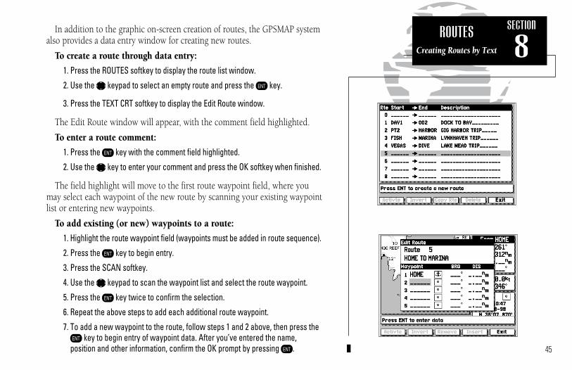
45
In addition to the graphic on-screen creation of routes, the GPSMAP systemalso provides a data entry window for creating new routes.
To create a route through data entry:
1. Press the ROUTES softkey to display the route list window.
2. Use the K keypad to select an empty route and press the C key.
3. Press the TEXT CRT softkey to display the Edit Route window.
The Edit Route window will appear, with the comment field highlighted.
To enter a route comment:
1. Press the C key with the comment field highlighted.
2. Use the K key to enter your comment and press the OK softkey when finished.
The field highlight will move to the first route waypoint field, where youmay select each waypoint of the new route by scanning your existing waypointlist or entering new waypoints.
To add existing (or new) waypoints to a route:
1. Highlight the route waypoint field (waypoints must be added in route sequence).
2. Press the C key to begin entry.
3. Press the SCAN softkey.
4. Use the K keypad to scan the waypoint list and select the route waypoint.
5. Press the C key twice to confirm the selection.
6. Repeat the above steps to add each additional route waypoint.
7. To add a new waypoint to the route, follow steps 1 and 2 above, then press theC key to begin entry of waypoint data. After you’ve entered the name, position and other information, confirm the OK prompt by pressing C.
SECTION
8ROUTES
Creating Routes by Text
215225manb.qxd 4/27/00 9:22 AM Page 45

46
The GPSMAP’s AUX softkey provides access to the various system, naviga-tion and interface setup menus used to customize your unit’s operation. Onceyou have pressed the AUX softkey, you’ll see a complete list of availableoptions listed by category. Each category on the list has its own submenu ofsetup options and functions which can be accessed by selecting an AuxiliaryMenu option with the K keypad and pressing C. Available options are:
System Setup Settings for operating mode, date/time format, enable/disable audio tone, screen contrast adjustment
Navigation Setup Position format; units of measure for distance, speed and depth; heading reference; Settings for map datum and map orientation
Timer/Alarm Setup Timers for count down and elapsed time; Alarms for clock time,anchor drag, waypoint proximity and off course
Interface Setup Input/output interface settings, beacon receiver frequency/bit rate
Proximity Waypoints List of any designated proximity waypoints along with on-screensymbol and proximity distance, also create new proximity wpts
Route Trip Planning Planning window providing route calculations for desired track,distance between waypoints, total fuel required and time enroute
Point-to-Point Planning Planning window to calculate trip distance, fuel usage, timeenroute and ETA between any two waypoint positions
Sunrise/Sunset Planning Sunrise/sunset times calculated for any waypoint position
Track Recording Enable/disable recording, settings for recording status and interval,options for erasing track memory and enabling TracBack route
Glossary Listings of basic information/definitions for navigation terms andon-screen abbreviations
SECTION
9AUXILIARY MENU
Menu Options
215225manb.qxd 4/27/00 9:22 AM Page 46

47
When an Auxiliary Menu option is selected and displayed, you’ll see a complete listing of available functions, with the current setting for each optionindicated. Once you’ve entered a submenu, you’ll use one of two data entryformats to enter most of your setup preferences:
The option window provides you with a list of menu choices from which youselect your preferences.
To select a menu choice from an options window:
1. Use the K key to highlight an option from the list.
2. Press the C key to see a list of menu options.
3. Use the K keypad to highlight your choice and press C.
The data entry window is used for settings that require entry of numerical oralphabetical values, and provides a table of values to enter characters.
To enter a value in a data entry window:
1. Use the K keypad to select a character value for each position. Press the Ckey to accept the value and move to the next character position.
2. Press the OK softkey to accept the data entry (pressing the key after the finalcharacter will also accept the data entry).
SECTION
9AUXILIARY MENUUsing Menu Options
215225manb.qxd 4/27/00 9:22 AM Page 47
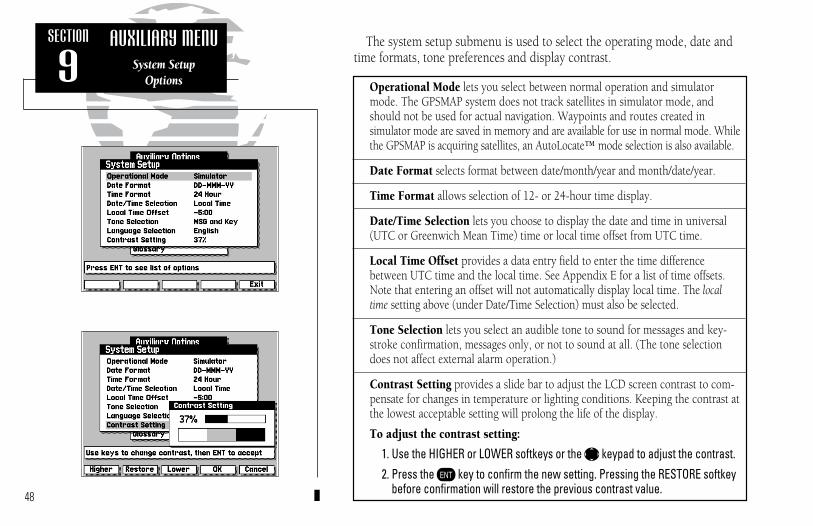
Operational Mode lets you select between normal operation and simulatormode. The GPSMAP system does not track satellites in simulator mode, andshould not be used for actual navigation. Waypoints and routes created in simulator mode are saved in memory and are available for use in normal mode. Whilethe GPSMAP is acquiring satellites, an AutoLocate™ mode selection is also available.
Date Format selects format between date/month/year and month/date/year.
Time Format allows selection of 12- or 24-hour time display.
Date/Time Selection lets you choose to display the date and time in universal(UTC or Greenwich Mean Time) time or local time offset from UTC time.
Local Time Offset provides a data entry field to enter the time differencebetween UTC time and the local time. See Appendix E for a list of time offsets.Note that entering an offset will not automatically display local time. The localtime setting above (under Date/Time Selection) must also be selected.
Tone Selection lets you select an audible tone to sound for messages and key-stroke confirmation, messages only, or not to sound at all. (The tone selectiondoes not affect external alarm operation.)
Contrast Setting provides a slide bar to adjust the LCD screen contrast to com-pensate for changes in temperature or lighting conditions. Keeping the contrast atthe lowest acceptable setting will prolong the life of the display.
To adjust the contrast setting:
1. Use the HIGHER or LOWER softkeys or the K keypad to adjust the contrast.2. Press the C key to confirm the new setting. Pressing the RESTORE softkey
before confirmation will restore the previous contrast value.48
The system setup submenu is used to select the operating mode, date andtime formats, tone preferences and display contrast.
SECTION
9AUXILIARY MENU
System SetupOptions
215225manb.qxd 4/27/00 9:22 AM Page 48
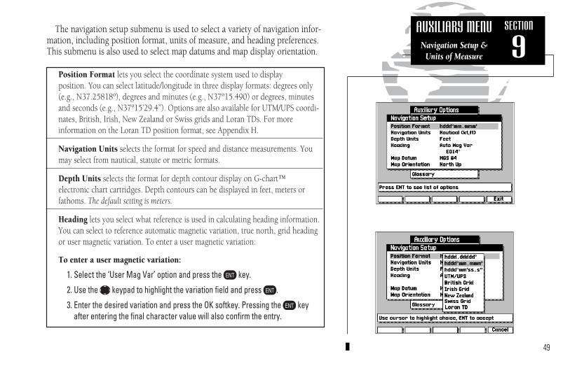
Position Format lets you select the coordinate system used to display position. You can select latitude/longitude in three display formats: degrees only(e.g., N37.25818º), degrees and minutes (e.g., N37º15.490) or degrees, minutesand seconds (e.g., N37º15’29.4”). Options are also available for UTM/UPS coordi-nates, British, Irish, New Zealand or Swiss grids and Loran TDs. For more information on the Loran TD position format, see Appendix H.
Navigation Units selects the format for speed and distance measurements. Youmay select from nautical, statute or metric formats.
Depth Units selects the format for depth contour display on G-chart™ electronic chart cartridges. Depth contours can be displayed in feet, meters orfathoms. The default setting is meters.
Heading lets you select what reference is used in calculating heading information.You can select to reference automatic magnetic variation, true north, grid headingor user magnetic variation. To enter a user magnetic variation:
To enter a user magnetic variation:
1. Select the ‘User Mag Var’ option and press the C key.
2. Use the K keypad to highlight the variation field and press C.
3. Enter the desired variation and press the OK softkey. Pressing the C keyafter entering the final character value will also confirm the entry.
49
The navigation setup submenu is used to select a variety of navigation infor-mation, including position format, units of measure, and heading preferences.This submenu is also used to select map datums and map display orientation.
SECTION
9AUXILIARY MENU
Navigation Setup & Units of Measure
215225manb.qxd 4/27/00 9:22 AM Page 49

The navigation setup submenu is also used to select map datums and adjustthe built-in position and velocity filters. The GPSMAP system’s default mapdatum is WGS 84, a worldwide map datum that’s suitable for use with mostgovernment charts. You should only change the map datum if the legend onthe charts you are currently using specifies a different map datum.
Using an incorrect map datum can seriously effect the accuracy of your GPSMAPnavigator. The map datum used on the GPSMAP should always match the datum ofthe chart you are using. If no datum information is indicated on the charts you areusing, contact the chart manufacturer. Selecting and defining a user datum is rec-ommended only for navigators with experience in global models and datums.
Map Datum provides a list of the available map datums for use with theGPSMAP system. For a list of the available GPSMAP datums, see Appendix F. A‘user’ datum option is also available to allow entry of your own datum corrections.
To define a user map datum:
1. Select the ‘User’ option from the datum list.
2. Enter the datum values in each field. The values you enter will be based ontheir difference from the WGS 84 datum.
3. Highlight the OK prompt and press C to confirm the user datum.
Map Orientation lets you specify whether the top of the map display remainsfixed at north (North Up); fixed along your desired course (DTK Up); or allow themap display to continually rotate, keeping your current ground track at the top ofthe display (Track Up). When any option other than North Up is selected, an indi-cator will appear on the map display to always show you where north is.
50
SECTION
9AUXILIARY MENU
Navigation Setup & Map Settings
I
215225manb.qxd 4/27/00 9:22 AM Page 50

Count Down timer controls an alarm to sound when an entered interval (up to99:59:59) has expired. Enter a time interval in the time field and use the controlfield to the immediate right to run, stop or reset the timer.
Elapsed Timer provides a running clock to 99:59:59. To run, stop or reset theelapsed time clock, highlight the control field to the right of the timer display,select the appropriate option.
Clock Alarm provides an alarm for the system clock. Enter a time in the time fieldand turn the alarm on and off from the control field menu. Remember to enteralarm times in the same time format (UTC or local) you’re using for your system.
Anchor Alarm lets you specify an alarm to sound when you’ve exceeded a speci-fied drift distance. Enter a distance up to 9.9 miles or kilometers in the distancefield and use the control field to turn the alarm on and off.
Arrival Alarm lets you specify an alarm to sound when you’re a specified dis-tance away from a destination waypoint. Enter a distance radius for sounding thealarm and use the control field to turn the alarm on and off. If the arrival alarm isturned off, the alarm will still sound one minute before reaching the destinationwaypoint at your current speed and course.
Prox Alarm lets you select an alarm to sound when you’re a specified distancefrom a proximity waypoint. Use the control field to turn the alarm on and off.Proximity waypoints and radius values are entered from the proximity waypointlist submenu (see page 56).
Off Course Alarm lets you select an alarm to sound when you’re off a desiredcourse by a specified distance. Enter a distance in the distance field and use thecontrol field to turn the off course alarm on and off.
51
The timer/alarm setup submenu is used to control the GPSMAP’s variousalarm and timer settings.
SECTION
9AUXILIARY MENU
Timer/Alarm Setup
215225manb.qxd 4/27/00 9:22 AM Page 51
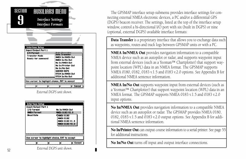
The GPSMAP interface setup submenu provides interface settings for con-necting external NMEA electronic devices, a PC and/or a differential GPS(DGPS) beacon receiver. The settings, listed at the top of the interface setupwindow, control a bi-directional I/O port with six (built in DGPS) or nine(optional, external DGPS) available interface formats:
Data Transfer is a proprietary interface that allows you to exchange data suchas waypoints, routes and track logs between GPSMAP units or with a PC.
NMEA In/NMEA Out provides navigation information to a compatibleNMEA device such as an autopilot or radar, and supports waypoint inputfrom external devices (such as a Yeoman™ Chartplotter) that support way-point location (WPL) data in an NMEA format. The GPSMAP supportsNMEA 0180, 0182, 0183 v.1.5 and 0183 v.2.0 options. See Appendix B foradditional NMEA sentence information.
NMEA In/No Out supports waypoint input from external devices (such asa Yeoman™ Chartplotter) that support waypoint location (WPL) data in anNMEA format. The GPSMAP supports NMEA 0183 v.1.5 and 0183 v.2.0input options.
No In/NMEA Out provides navigation information to a compatible NMEAdevice such as an autopilot or radar. The GPSMAP provides NMEA 0180,0182, 0183 v.1.5 and 0183 v.2.0 output options. See Appendix B for addi-tional NMEA sentence information.
No In/Printer Out can output course information to a serial printer. See page 55for additional instructions.
No In/No Out turns off input and output interface connections.
52
SECTION
9AUXILIARY MENU
Interface SettingsInterface Formats
External DGPS unit shown.
External DGPS unit shown.
215225manb.qxd 4/27/00 9:22 AM Page 52
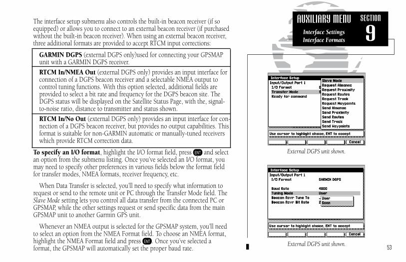
53
The interface setup submenu also controls the built-in beacon receiver (if soequipped) or allows you to connect to an external beacon receiver (if purchasedwithout the built-in beacon receiver). When using an external beacon receiver,three additional formats are provided to accept RTCM input corrections:
GARMIN DGPS (external DGPS only)used for connecting your GPSMAP unit with a GARMIN DGPS receiver.
RTCM In/NMEA Out (external DGPS only) provides an input interface for connection of a DGPS beacon receiver and a selectable NMEA output to control tuning functions. With this option selected, additional fields are provided to select a bit rate and frequency for the DGPS beacon site. TheDGPS status will be displayed on the Satellite Status Page, with the, signal-to-noise ratio, distance to transmitter and status shown.
RTCM In/No Out (external DGPS only) provides an input interface for con-nection of a DGPS beacon receiver, but provides no output capabilities. Thisformat is suitable for non-GARMIN automatic or manually-tuned receiverswhich provide RTCM correction data.
To specify an I/O format, highlight the I/O format field, press C and selectan option from the submenu listing. Once you’ve selected an I/O format, youmay need to specify other preferences in various fields below the format fieldfor transfer modes, NMEA formats, receiver frequency, etc.
When Data Transfer is selected, you’ll need to specify what information torequest or send to the remote unit or PC through the Transfer Mode field. TheSlave Mode setting lets you control all data transfer from the connected PC orGPSMAP, while the other settings request or send specific data from the mainGPSMAP unit to another Garmin GPS unit.
Whenever an NMEA output is selected for the GPSMAP system, you’ll needto select an option from the NMEA Format field. To choose an NMEA format,highlight the NMEA Format field and press C. Once you’ve selected a format, the GPSMAP will automatically set the proper baud rate.
SECTION
9AUXILIARY MENU
Interface SettingsInterface Formats
External DGPS unit shown.
External DGPS unit shown.
215225manb.qxd 4/27/00 9:22 AM Page 53

When equipped with a built-in beacon receiver or external DGPS receiver,the GPSMAP system can automatically scan for the DGPS beacon signal or youmay manually enter a frequency and bit rate. DGPS status will be displayed onthe Satellite Status Page (only when the unit is in 2D or 3D nav mode), alongwith the, signal-to-noise ratio (SNR) and distance to transmitter (if available).
If your GPSMAP contains an internal DGPS beacon receiver, it is not necessary to select ‘GARMIN DGPS’ or ‘RTCM In/NMEA Out’ from theInterface Setup Menu. The GPSMAP will automatically display the frequencyand bit rate settings for the beacon receiver at the bottom of the Interface SetupMenu. The DGPS beacon transmitters are operated by the U.S. Coast Guard (or similar government agency in other countries), which is responsible for theiraccuracy and maintenance. For DGPS transmitter problems or to find the mostupdated list of frequencies & coverage areas, contact your local USCG, or seetheir web site at http://www.navcen.uscg.mil/.
To have the unit automatically scan for a frequency:1. With the unit set to ‘Garmin DGPS’ or ‘RTCM In/NMEA Out’, use the
K key to highlight the “Tuning Mode” field and press C.
2. Highlight ‘Scan’ and press C. The numbers in the “ Tune To” and
“Bit Rate” Beacon Rcvr fields will change as the unit scans from
284 kHz to 325 kHz 200 bit rate, then 100, at 6-second intervals.
To manually enter a frequency and bit rate:1. With the unit set to ‘Garmin DGPS’ or ‘RTCM In/NMEA Out’, use the
K key to highlight the “Tuning Mode” field and press C.
2. Highlight ‘User’ and press C.
3. Highlight the “Tune To” or “Bit Rate” Beacon Rcvr fields, press
C, then enter a frequency or bit rate and press C when done.54
SECTION
9AUXILIARY MENU
Interface SettingsInterface Formats
Internal DGPS unit shown.
Internal DGPS unit shown.
215225manb.qxd 4/27/00 9:22 AM Page 54

The “Bcn Rcvr” field on the Status Page will show one of the following:• Tuning— unit is attempting to tune to the specified frequency and bit rate.• Scanning— unit is automatically scanning through the frequencies and bit rates.• Receiving— unit is receiving DGPS signal and ready for operation.• Check Wiring— unit is not making connection with an external DGPS receiver. • No Signal— unit is not receiving a DGPS signal for the specified frequency.
When the unit is receiving a DGPS signal, the “SNR” (Signal to Noise Ratio)and “Distance” fields will show data. The SNR range is 0dB to 30dB, with 30being the best. The Distance may or may not show data, depending upon thesignal being broadcast from the DGPS site.
No In/Printer Out can output course information to a serial printer.
To enable the serial printer output:1. Activate the Interface Setup Menu.2. Using the K key, highlight the ‘I/O Format’ field and press C.3. Using the K key, select ‘No In/Printer Out’ on the selection list and press C.
The Baud Rate can be set to a range between 300 - 9600. To change the Baud Rate:
1. Using the K key, highlight the ‘Baud Rate’ field and press C.2. Using the K key, select the desired baud rate and press C.
The Output Interval can be set to a time between 3 seconds and 9 hours.
To change the Output Interval:1. Using the K key, highlight the ‘Output Interval’ field and press C.2. Using the K key, enter the desired time pressing C to access the next digit. 3. To accept the new time press C. 55
SECTION
9AUXILIARY MENU
Interface SettingsInterface Formats
Internal DGPS unit shown.
External DGPS unit shown.
215225manb.qxd 4/27/00 9:22 AM Page 55

If a proximity alarm circle overlaps with anexisting alarm circle, a ‘proximity overlap’warning will be displayed. As long as the over-lap exists, the overlap warning will be dis-played each time the GPSMAP is turned on.
If you enter an alarm circle overlap, theGPSMAP will only inform you of the closestproximity waypoint.
56
The next submenu listing on the Auxiliary Menu is the proximity waypoints list. The proximity waypoints list lets you define an alarm circlearound a stored waypoint position, and can be used to help you avoid reefs,rocks or restricted waters. Up to nine waypoints may be listed, with a maximum alarm radius of 99.9 nautical or statute miles or kilometers. Thealarm is turned on and off through the alarm/timer setup submenu.
To enter a proximity waypoint:
1. Highlight a blank proximity waypoint name field on the list and press C.
2. Press the C key to begin manually entering the waypoint name, or
3. Press the SCAN softkey to scan through all waypoints in memory.
4. Use the K keypad to select the desired waypoint and press C.
5. Press the OK softkey (twice if entering waypoint name manually). The radiusfield will now be highlighted.
6. Press C to begin entry of the proximity radius.
7. Use the K keypad to enter a distance value and press C.
To review a proximity waypoint from the list:
1. Use the K key to highlight the waypoint to be reviewed.
2. Press the C key.
3. Press the C key again to return to the proximity list.
To remove a proximity waypoint from the list:
1. Use the K key to highlight the waypoint to be removed.
2. Press the REMOVE softkey.
SECTION
9AUXILIARY MENU
Proximity Waypoints List
215225manb.qxd 4/27/00 9:22 AM Page 56

57
The GPSMAP system features a route planning window that will calculateand display the desired track and distance to route waypoints, along with thetotal fuel required and estimated time enroute (ETE).
To use the route planning mode:
1. Highlight the Route Trip Planning option from the Auxiliary Options window andpress the C key.
2. Use the PREV RTE and NEXT RTE softkeys to select a route.
3. Highlight the speed field and enter a speed for your trip.
4. Highlight the fuel flow field and enter a units per hour flow.
5. Highlight the departure date field and enter a date.
6. Highlight the departure time field and enter a departure time.
The starting route waypoint is indicated under the departure date field, witha list of the remaining route waypoints in sequence below. The distance, fuelrequired and ETE displayed are the total values from the starting waypoint toeach listed waypoint, with the desired track representing the course betweenany two route waypoints.
From the route waypoint list, you can use the K keypad to scroll throughthe entire list and review individual route legs by highlighting the desired destination waypoint and pressing the C key.
The Point-To-Point route planning window lets you review leg totals for distance, fuel required and ETE. The estimated time of arrival (ETA), alongwith the sunrise and sunset at your destination are also displayed. You can usethe leg planning window to perform additional speed, fuel and time calcula-tions. To return to the main route planning page, press the EXIT softkey.
SECTION
9AUXILIARY MENURoute Trip Planning
215225manb.qxd 4/27/00 9:22 AM Page 57
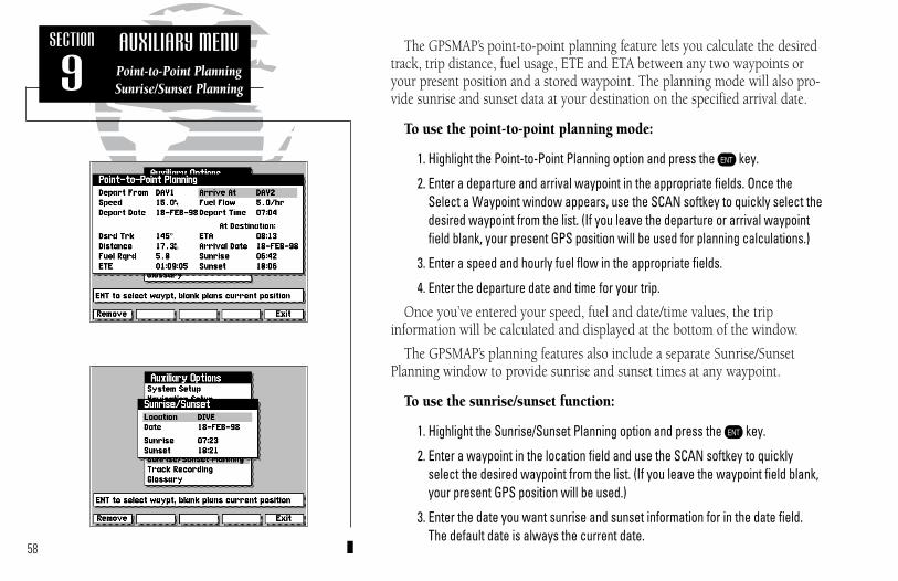
58
The GPSMAP’s point-to-point planning feature lets you calculate the desiredtrack, trip distance, fuel usage, ETE and ETA between any two waypoints oryour present position and a stored waypoint. The planning mode will also pro-vide sunrise and sunset data at your destination on the specified arrival date.
To use the point-to-point planning mode:
1. Highlight the Point-to-Point Planning option and press the C key.
2. Enter a departure and arrival waypoint in the appropriate fields. Once theSelect a Waypoint window appears, use the SCAN softkey to quickly select thedesired waypoint from the list. (If you leave the departure or arrival waypointfield blank, your present GPS position will be used for planning calculations.)
3. Enter a speed and hourly fuel flow in the appropriate fields.
4. Enter the departure date and time for your trip.
Once you’ve entered your speed, fuel and date/time values, the trip information will be calculated and displayed at the bottom of the window.
The GPSMAP’s planning features also include a separate Sunrise/SunsetPlanning window to provide sunrise and sunset times at any waypoint.
To use the sunrise/sunset function:
1. Highlight the Sunrise/Sunset Planning option and press the C key.
2. Enter a waypoint in the location field and use the SCAN softkey to quicklyselect the desired waypoint from the list. (If you leave the waypoint field blank,your present GPS position will be used.)
3. Enter the date you want sunrise and sunset information for in the date field.The default date is always the current date.
SECTION
9AUXILIARY MENUPoint-to-Point PlanningSunrise/Sunset Planning
215225manb.qxd 4/27/00 9:22 AM Page 58

Recording Status lets you define how track plot memory will be used:
Off– no track plot will be recorded. (NOTE: Selecting ‘Off’ will prevent youfrom using the TracBack feature.)
Fill– a track plot will be recorded until track memory is full.
Wrap (default)– a track plot will be continuously recorded, wrapping throughthe available memory (replacing the oldest track data with new data).
Recording Interval defines the frequency with which the track plot is recorded:
Time– records track plot based upon a user-defined time interval.
Distance– records track plot based upon a user-defined distance between points.
Resolution– records track plot based upon a user-defined variance from yourcourse over the ground. This setting is recommended for the most efficient useof track memory and TracBack performance. The distance value (entered in theInterval Value field) is the maximum left/right deviation allowed from the lastdefined ground track before recording a new track point.
Interval Value defines the distance or time interval used to record the track plot.
Erase Track Memory lets you clear all track plot data currently stored in memory.
To erase the track plot memory:
1. Highlight the Erase Track Memory field and press C.
2. Move the field highlight to the ‘Yes’ prompt and press the C key.59
The GPSMAP’s track recording submenu lets you specify whether or not torecord a track plot (an electronic recording of your path) and define how it isrecorded. It also provides an indicator of the track memory used, and functionsto clear the track memory or create a TracBack route.
SECTION
9AUXILIARY MENU
Track RecordingConfiguration
The ‘Track Memory Used’ field displays the percentage of available memory currentlybeing used. If you are nearing 100% capacity,you can download (and save) the track datato a PC using an optional PC Software kit.
Track plot data may also be converted into aroute by using the ‘Start TracBack?’ option.See page 60 for more information on this feature.
215225manb.qxd 4/27/00 9:22 AM Page 59

SECTION
9AUXILIARY MENU
Track RecordingTracBack
Start TracBack allows you to retrace your path using the track plot automaticallystored in the receiver’s memory. This eliminates the need to manually store way-points along the way. A track plot is an electronic breadcrumb trail, showing thepath you have travelled. Your GPSMAP can be set to automatically record trackplot points any time the receiver is on and locked onto satellites (see page 59).
TracBack routes are created by reducing your track plot into a route of up to 50waypoints and activating the new route in reverse order along those waypoints.Once activated, a TracBack route will lead you back to the oldest track plot pointstored in memory, so it’s a good idea to erase the track memory at the beginning ofyour current trip (e.g., at the dock), before you get started (see page 59).
To create and activate a TracBack route:
1. Enable track plot recording and leave the GPSMAP on to automaticallyrecord track log positions while underway (see page 59).
2. Select the Start TracBack option from the track recording submenu andpress C to create/activate the TracBack route. (A message box will appearwhile the GPSMAP analyzes the data and creates the route.)
The TracBack route will contain waypoints (labeled ‘T###’, e.g. ‘T001’) whichmark the most significant features of the original track plot in order to duplicateyour path as closely as possible. To gain the most benefit from the TracBack feature, keep the following tips in mind:
• Always clear the track plot at the point you wish to return to (ramp, dock, etc.)• The Recording Status must be set to ‘Wrap’ or ‘Fill’.• There must be at least two track plot points stored in memory to create a route.• If the Recording Interval is set to ‘Time’ or ‘Distance’, the route may not closely
follow your path. Use ‘Resolution’ for best results. • If the receiver is turned off or satellite coverage is lost during your trip,
TracBack will draw a straight line between any point where coverage was lostand where it resumed.
60
215225manb.qxd 4/27/00 9:22 AM Page 60

61
SECTION
9AUXILIARY MENU
On-Screen GlossaryViewing Messages
The last listing on the auxiliary options menu is the glossary function. TheGPSMAP’s on-screen glossary contains basic information on general navigationterms and abbreviations, as well as helpful hints on using your unit.
To use the on-screen glossary:
1. Highlight the Glossary option from the Auxiliary Options window and press theC key.
2. Use the PREV PG and NEXT PG softkeys to scroll through the glossary listings.
The Auxiliary Options window is also used to access any current messagesin your unit. There are two types of messages used in the GPSMAP system:temporary messages (eg. approaching a waypoint) and condition messages (eg. no DGPS position). All message are initially indicated by a flashing on-screen alert (and a tone, if specified). After a temporary message has beenacknowledged (by pressing the C key), it is cleared from the screen.Condition messages will remain displayed in the messages window until thecondition has been resolved.
To view condition messages:
1. From the Auxiliary Options window, press the MESSAGE softkey.
2. To return to the Auxiliary Options window, press the C key.
215225manb.qxd 4/27/00 9:22 AM Page 61

The GARMIN GPSMAP system uses G-chart™ digital cartography to displaynautical charts on-screen. G-chart™ inland and offshore cartridges are installedin the card slot located at the bottom right of the GPSMAP unit. G-chart™ car-tridges may be installed or removed at any time, whether the unit is on or off.
To install a G-chart™ cartridge:
1. Turn the latch ring 1/4 turn counterclockwise and open the cartridge door.2. Insert the card (label facing front and G-chart™ logo at top) into the slot.3. Use your thumb to firmly push the cartridge into place, until the cartridge will
not go any further into the unit. 4. If your GPSMAP is on, a confirmation tone will sound when the cartridge has
been properly installed and accepted.5. Close the cover and turn the latch ring 1/4 turn clockwise to secure. The car-
tridge door features a sealing gasket to keep moisture out of the G-chart™ area.
If you insert a G-chart™ cartridge and get a ‘card format not recognized’ message,try removing the card and reinserting it. If the card is still not recognized, contact thedealer you purchased it from for assistance. G-chart™ cartridges are not waterproof, and should not be exposed to moisture or static discharges.
To remove a G-chart™ cartridge:
1. Turn the latch ring 1/4 turn counterclockwise and open the cartridge door.2. Grasp the card at the bottom groove and pull firmly to remove.3. If your GPSMAP is on, a confirmation tone will sound when the G-chart™
cartridge has been removed.
62
SECTION
10G-CHART CARTRIDGESInserting & Removing
Cartridges
I
Cartridge Door Latch Ring
215225manb.qxd 4/27/00 9:22 AM Page 62

63
Once a G-chart cartridge has been inserted, the map coverage outlines for thecartridge will automatically appear on screen. Keep in mind that the displaywill not automatically scroll to the map area or zoom to a level where you cansee the coverage outlines. If you do not immediately see the outlines, scroll thecursor to the broad geographic area covered by the chart and/or zoom out toanother map scale. You may have to press the E key to display the outlines.
The large outline box shown is the main chart, which serves as the boundary area for the entire cartridge. The smaller boxes inside the main boxare subcharts, which provide more detailed coverage of the area indicated. Toview the detailed cartography of any subchart, scroll the cursor to the subchartoutline and use the L key to zoom in to smaller range scales.
Whenever you zoom past the usable range of the current electronic chart, the rangefield will display ‘Ovr Zm’ or ‘No Map’. These warnings indicate that although youmay still have cartography, you should exercise extreme caution using the data. Seepage 20 for more information on Overzoom and No Map modes.
When a G-chart cartridge is installed, the GPSMAP system will automatical-ly use the best available chart for display. As you enter and exit various sub-charts, the system will automatically display the appropriate chart for the areayou are in. When you leave the area covered by the main map of a cartridge,the GPSMAP will default back to using the built-in worldwide database if it isavailable at the current scale. Once you’ve inserted a cartridge, the coverageoutlines can be turned off to keep the display as uncluttered as possible.
To turn the map outlines on or off:
1. Press the E key.
SECTION
10G-CHART CARTRIDGESG-chart Map Scales
Displaying Map Outlines
I
215225manb.qxd 4/27/00 9:22 AM Page 63

Some G-chart™ cartridges include port services information, which listsavailable services and facilities for the selected area. When this information isavailable, a port services ‘information’ icon will appear on the map display(typically at lower scale settings only).
To view port services information:
1. Use the K keypad to place the panning cursor on a port services informationicon. Once the icon is selected, an information box appears (at lower right corner of the screen) showing the name of the selected port.
2. Press C to display the full listing of available services.
3. Use the NEXT PG and PREV PG softkeys to view additional pages of information.
At this writing, port services information is available on many G-chart™ cartridgesthroughout Europe, with plans underway to expand this coverage worldwide.
64
SECTION
10G-CHART CARTRIDGES
Port ServicesInformation Port Services
InformationIcons
I
215225manb.qxd 4/27/00 9:22 AM Page 64

Your GPSMAP system includes the following hardware components:
GPSMAP UnitGimbal Mount Bracket (with knobs)GPS Antenna with 30’ cablePower/Data Cable2-amp in-line fuse (included with Power/Data cable)Antenna Combiner (for GPSMAP purchased with built-in DGPS)Antenna Coupler and Whip Antenna (for GPSMAP purchased withbuilt-in DGPS)
If you are missing any of the above pieces, see your dealer. To complete thestandard installation, you’ll also need the following additional:
Four 1/4” (6 mm) diameter mounting screws1” x 14 thread antenna mounts (Two for GPSMAP with built-in DGPS)
Several optional accessories are also available to provide flexible installationon any vessel. See your GARMIN dealer for more information on these items:
GA23 H-Field antenna.Flush Mount Kit30’ Antenna Cable Extension110/220 volt AC adapterCigarette Lighter Adapter
Reading through the entire installation section before starting your installation willhelp you get the most out of your GARMIN navigation system. An improper or poorlyplanned installation can affect the GPS receiver’s accuracy, overall performanceand your ability to satisfactorily use the GPSMAP system.
65
WARNING!The GPSMAP system has no user-serviceableparts, and you should never attempt anyrepairs yourself. The unit is gasket-sealed toprevent moisture penetration. Opening thecase or loosening any fittings may exposeinternal components to moisture and willvoid the manufacturer’s warranty!
For warranty and service details, see page iiiat the front of this manual.
SECTION
AAPPENDIX Installation
I
215225manb.qxd 4/27/00 9:22 AM Page 65

To begin installation, you’ll need to select a suitable mounting position forthe antenna(s) and the GPSMAP unit. Once you’ve identified the best mountinglocations for your application, install the antenna(s) and its cable(s) first, thenthe unit and power/data cable.Mounting the antenna(s)
The GPS antenna should be mounted in a location that has a clear, unobstructed view of the sky in all directions to ensure the best reception in all conditions. Avoid mounting the antenna where it will be shaded by the boat’ssuperstructure, a radome antenna, or mast.
The beacon antenna provides more flexibility in mounting locations. Mounting near objects which partially shade its field of view is not a critical concern, however large metal objects may create enough obstruction to degradereception and performance. As a general rule, mount the antenna at least 3 feet.from all other antennas and the vessel’s alternator/ignition system components. Aground strap is attached to the antenna coupler, except on the GA 23 H-fieldantenna. For proper operation, the ground strap must be connected to a vessel (earth)ground. Do not ground the coupler to the electrical system.
GARMIN antennas screw directly onto any standard 1” x 14 thread antennamount. If you need to raise an antenna to avoid shading, try using a 1” x 14thread extension mast available at most marine dealers.
To install the antenna(s):1. Screw the antenna directly onto the 1” x 14 thread mount.2. Route the cable to the mounting location of the display unit, using the appropri-
ate tie-wraps, escutcheon plates and sealant to secure the cable along the routeand through any bulkhead or deck.
3. Once the GPSMAP unit has been installed, connect the cable to the antennaconnector on the back of the unit. Make sure that you turn the antenna 1/4 turnclockwise to lock the cable into place. (For models purchased with built-inDGPS, connect each antenna cable to the Antenna Combiner. Then use the sup-plied short cable to connect the Antenna Combiner to the back of the unit.)
66
SECTION
AAPPENDIX Installation
CAUTION!Cutting or modifying the antenna(s)may result in undesired operationof the GPS. If the standard cable isnot long enough for your applica-tion, see your dealer for the properGARMIN cable extension. When indoubt, seek the assistance of a qualified installation technician.
215225manb.qxd 4/27/00 9:22 AM Page 66

Antenna connection for GPSMAP system with built-in DGPS
Antenna connection for GPSMAP system without built-in DGPS:
GPSMAP systems without the built-in DGPS beacon receiver do not includethe antenna combiner and antenna coupler. The GPS antenna is connecteddirectly to the BNC connector on the back of the unit. DGPS capability can beadded, as an option, by purchasing an external beacon receiver—such asGARMIN’s GBR 21/23.
Connections to an external beacon receiver are made using the NMEA IN,NMEA OUT (for GBR 21/23 only) and GROUND connections on the suppliedpower/data cable. See the beacon receiver owner’s manual for connectioninformation not covered in the above diagram. 67
SECTION
AAPPENDIXInstallation
A second 1” x 14 thread antenna mount is neededwhen installing a GPSMAP with built-in DGPSbeacon receiver. The second mount is used for the
antenna coupler and whip antenna.Connect the antenna coupler’s ground strap to a vessel(earth) ground. An earth ground connection can usually be made by connecting to a thru-hull fitting,engine block, dynaplate or body of a metal vehicle.
Note: The GA 23 H-field antenna does not requiregrounding.
GPS Antenna
Antenna Combiner
Beacon Antennaand Coupler
GPSMAP 215/225(rear view)
BNC ConnectorPWR/DATA
215225manb.qxd 4/27/00 9:22 AM Page 67

Mounting the GPSMAP unit
The GARMIN GPSMAP’s fully gasketed and sealed case is suitable for mount-ing in exposed locations or at the nav station. The unit comes with a gimbalbracket that can be used for surface or overhead mounting. When choosing alocation for the display unit, make sure you consider the following conditions:
• There should be at least 3.25” (8.25 cm) clearance behind the case toallow connection of the antenna and power/data cables.
• Provide adequate clearance for the G-chart cartridge cover to swingopen freely. You may swivel the unit to get a firm grip on the cartridge.
• The mounting surface should be heavy enough to support the unit andprotect it from excessive vibration and shock.
• The GPSMAP 215 screen will provide crisp contrast in most lightingconditions, even in full sunlight. Because of the technology used in TFTscreens, the GPSMAP 225 performs best in shaded conditions, protect-ed from direct sunlight.
To install the GPSMAP unit:
1. Place the mounting bracket in the desired location.
2. Mark and drill the four mounting holes for the fasteners you are using.
3. Fasten the bracket to the surface using the appropriate fasteners.
4. Insert the GPSMAP into the mounting bracket. The bracket is designed for atight fit to provide additional support when swiveling the unit.
5. Screw the two mounting knobs through the bracket and into the display case.
6. Connect the power/data and antenna cables to the back of the unit, makingsure the locking rings are fully tightened on both connectors.
WARNING!The temperature range for GPSMAP units is from -4 to +158ºF (-20- 70ºC). Extendedexposure to temperatures exceeding this range(in storage or operating conditions) may causefailure of the LCD screen. This type of failureand related consequences ARE NOT coveredby the manufacturer’s warranty.
68
SECTION
AAPPENDIXInstallation
215225manb.qxd 4/27/00 9:22 AM Page 68

69
Connecting the power/data cable
The power/data cable connects the GPSMAP system to a 10-40 volt DCpower source and provides interface capabilities for connecting NMEA devices,an external beacon receiver (if not equipped with built-in DGPS), and anexternal alarm (see section 9 for interface operation details). The color code inthe diagram below indicates the appropriate harness connections.
To connect the GPSMAP to a power source:
1. Connect the RED harness lead to the positive side of a 10-40 volt DC powersource. Make sure the power lead has an in-line 2-amp fuse installed.
2. Connect the BLACK harness lead to a ground strip or the negative side of a 10-40 volt DC power source.
The GPSMAP system will interface to RS-232 devicesusing NMEA data, to an external alarm device, andto a PC (see PC connection info above).
To connect to an NMEA device, use the BLUE (out)and BLACK (ground) harness leads. Some deviceswill support bi-directional data exchange. For thosedevices you must also use the BROWN (in) lead.
To connect an external alarm (100 mA max. coil current), connect the ground side of the alarm deviceor relay to the YELLOW harness lead.
SECTION
BAPPENDIX
Wiring Installation
PIN 1 (red): 10-40 volts DC
PIN 2 (black): Ground
PIN 3 (blue): NMEA out
PIN 4 (brown): NMEA in
PIN 5 (white): no connect
PIN 6 (green): no connect
PIN 7 (yellow): alarm low
Connect the harness leadsfrom the GPS to a 9-pin serialconnector:BLUE (Data Out) - Pin 2BROWN (Data In) - Pin 3BLACK (Ground) - Pin 5
PC Connections
DB-9
12345
679 8
1
2
34
5
6
7
Pin assignment(CABLE VIEW)
(-) (+)
10-40 volts DC
Autopilot/NMEA Device
GBR 21/23BeaconReceiver
(for GPSMAP w/obuilt-in DGPS)
Alarm/Relay
(-)
Shield Grounded Through GPS
(+)
(+)
(-)
(-)
OUT
IN
(+)
215225manb.qxd 4/27/00 9:22 AM Page 69

Complete information concerning NMEA formats and sentences is available for purchase from NMEA at:
NMEAPO Box 3435
New Bern, NC 28564-3435252-638-2626
252-638-4885 FAX.
70
The following interface formats are supported by the GPSMAP system for connection to up to three NMEA devices (GPSMAP units with built-in DPGSdo not support RTCM DGPS corrections data inputs or the PSLIB beaconreceiver control sentence output):
NMEA 0180
NMEA 0182
NMEA 0183 version 1.5Approved sentences—
GPBWC, GPGLL, GPRMB, GPRMC, GPXTE, GPVTG, GPWPL
Proprietary sentences—PGRMM (map datum), PGRMZ (altitude), PSLIB (beacon receiver control input)
NMEA 0183 version 2.0Approved sentences—
GPGGA, GPGSA, GPGSV, GPRMB, GPRMC, GPRTE, GPWPLProprietary sentences—
PGRME (estimated error), PGRMM (map datum)PGRMZ (altitude), PSLIB (beacon receiver control input)
DGPS corrections are accepted in RTCM-104 v. 2.0 format through theNMEA in (BROWN) harness lead. The GARMIN GBR 21 or GBR 23 are therecommended beacon receivers for use with the GPSMAP system.Otherreceivers with the correct RTCM format may be used, but may not correctlydisplay DGPS status on the GPSMAP display or allow tuning control from theGPSMAP unit.
SECTION
BAPPENDIX
NMEA Formats
215225manb.qxd 4/27/00 9:22 AM Page 70

GPSMAP Specifications
PHYSICAL
Case: Fully gasketed, high-impact plastic alloy
Size: 5.8”H x 9”W x 3”D(14.7 x 22.9 x 7.6 cm)
Weight: Less than 3 lbs. (1.4 kg)
Temperature Range: -4º to 158ºF (-20º to 70ºC)
PERFORMANCE
Receiver: Differential-ready 12 parallel channel
Acquisition Time: Approx. 15 seconds (warm)Approx. 45 seconds (cold)Approx. 5 minutes (AutoLocate™)
Update Rate: 1/second, continuous
Position Accuracy: 1-5 meters (3-15 ft.) with DGPS corrections*15 meters (49 ft.) RMS**
Velocity Accuracy: 0.1 knot RMS steady state
Dynamics: 6g’s
POWER
Input: 10-40vDC
Usage: 15 watts max. / 9 watts typical (215) 25 watts max. / 13 watts typical (225)
Specifications subject to change without notice.
* With built-in DGPS beacon receiver orexternal GARMIN GBR 21 or GBR 23Beacon Receiver Input.
** Subject to accuracy degradation to 100m 2DRMS under the United StatesDepartment of Defense-imposed Selective Availability Program.
71
SECTION
CAPPENDIX
Physical Specifications
215225manb.qxd 4/27/00 9:22 AM Page 71

The GPSMAP system uses an on-screen message field to alert you to important information. Whenever a message appears,press the C key to confirm the message.
There are two types of messages: temporarymessages and condition messages. Temporarymessages are cleared from the message pageafter viewing, while condition messagesremain in the message window until the condition has been resolved.
To view the message window, press the MESSAGES softkey from the AuxiliaryOptions Window. Pay careful attention to all messages for your own safety.
72
Alarm Clock—The alarm clock time has been reached and the alarm has sounded.
Anchor Drag Alarm—You have drifted out of the specified distance range.
Antenna Input Shorted to Ground—The GPSMAP has detected a short on theantenna connection. Check the connection, combiner (if used) and cable(s).Modifying cables (shortening or changing connectors) can also cause this condition ifdone improperly and may void your warranty.
Approaching—You are less than one minute away from reaching a destination way-point at your present speed over ground.
Arrival At—You are within the distance specified on the timer/alarm setup fromreaching your final destination waypoint.
Can’t Change Active Waypoint—You have attempted to change the ‘active to’ or‘active from’ waypoint. Clear the active route or GOTO before making your changes.
Card Format Not Recognized—The cartridge you have inserted is not readable bythe GPSMAP system and may be damaged. Reinsert the cartridge and make sure it isproperly installed.
Database Memory Failed—The built-in 64 n.m. database has failed. See an autho-rized service center for repair.
Degraded Accuracy—The accuracy of the GPSMAP has been degraded beyond 500 meters due to poor satellite geometry or data quality. You should check othernavigational sources to verify the position indicated.
Display ROM Failed—The graphic processor read-only memory has failed and theunit is no longer operable. See an authorized GARMIN service center for repair.
Max Calibration Is 5000mt (16,400 ft)—You have exceeded the maximum possi-ble map calibration.
SECTION
DAPPENDIX
Messages
215225manb.qxd 4/27/00 9:22 AM Page 72

73
Memory Battery Low—The internal lithium battery that maintains waypoint, routeand track plot memory (when the unit is off) needs to be replaced. Take your unit toan authorized GARMIN service center for installation of a new battery.
No DGPS Position—Not enough data is being received to compute a DGPS positionor unit has lost DGPS signal. Make sure the antenna coupler is properly grounded (seeAppendix A-Installation) and the correct frequency and bit rate are selected on theInterface Setup page.
Off Course Alarm—You have exceeded the off-course distance (left or right) specified in the timer/alarm setup.
Oscillator Needs Adjustment—The GPSMAP has detected excessive drift in itsinternal oscillator which may result in longer acquisition times. Take your unit to anauthorized GARMIN service center for adjustment.
Poor GPS Coverage—The GPSMAP cannot acquire the necessary number of satellitesto compute a position.
Power Down and Re-init—The GPSMAP cannot calculate a position due to abnormalsatellite conditions. Power down and verify the last position shown by other means.
Proximity Alarm—You have entered the alarm radius specified for the proximitywaypoint indicated.
Proximity Overlap—The alarm radius specified overlaps the area specified for another proximity waypoint. See section 9 for more information on proximity over-laps.
RAM Failed—The random access memory has failed and the unit is not operable.Take your unit to an authorized GARMIN service center for repairs.
ROM Failed—The permanent memory has failed and the unit is not operable. Takeyour unit to an authorized GARMIN service center for repairs.
SECTION
DAPPENDIX
Messages
GPSMAP Units with Built-in DGPSA DGPS beacon receiver is contained withinthe GPSMAP package. No interface connec-tions are required other than connection ofantenna combiner and antennas.
215225manb.qxd 4/27/00 9:22 AM Page 73

74
Received Invalid Waypoint—A waypoint was received during upload transfer thathas an invalid identifier.
Receiver Failed—A failure in receiver hardware has been detected. If this messagepersists, do not use the unit and take it to an authorized dealer for repair.
Route is Full—You have attempted to add more than 50 waypoints to a route.
Route Waypoint Deleted—A route waypoint entered does not exist in the databaseand has been deleted from the route.
Searching the Sky—The GPSMAP is in searching the sky for almanac data or the unitis in AutoLocateTM mode.
Stored Data Lost—All waypoints, routes and almanac data has been lost due tointernal battery failure.
Timer Expired—The countdown timer has expired.
Track Memory Full—The track memory is full and no additional track plot will berecorded until the track memory has been cleared or set to wrap mode (see page 59).
Transfer Completed—The receiver is finished uploading or downloading information to the connected device.
User Card Operation Complete—The user card data transfer has been completed.
Waypoint Exists—The waypoint name you’re entering already exists in memory.
Waypoint Memory Full—You have used all available waypoints in the GPSMAP unit.
SECTION
DAPPENDIX
Messages
215225manb.qxd 4/27/00 9:22 AM Page 74

75
The chart below gives an approximate UTC(Universal Time Coordinate) time offsetfor the various longitudinal zones. Check with local charts for more detailed informa-tion. If you are in daylight savings time, add one hour to the offset.
Longitudinal Zone OffsetW180.0º to W172.5º -12W172.5º to W157.5º -11W157.5º to W142.5º -10W142.5º to W127.5º -9W127.5º to W112.5º -8W112.5º to W097.5º -7W097.5º to W082.5º -6W082.5º to W067.5º -5W067.5º to W052.5º -4W052.5º to W037.5º -3W037.5º to W022.5º -2W022.5º to W007.5º -1W007.5º to E007.5º 0E007.5º to E022.5º +1E022.5º to E037.5º +2E037.5º to E052.5º +3E052.5º to E067.5º +4E067.5º to E082.5º +5E082.5º to E097.5º +6E097.5º to E112.5º +7E112.5º to E127.5º +8E127.5º to E142.5º +9E142.5º to E157.5º +10E157.5º to E172.5º +11E172.5º to E180.0º +12
SECTION
EAPPENDIXTime Offsets
A simple way to determine your local timeoffset is how many hours you are behindor ahead of UTC (also called ‘Greenwich’or ‘zulu’ time).
Example: EST(Eastern Standard Time) is5 hours behind UTC, so your offset wouldbe -5. Adding one hour for daylight savings would make EDT(EasternDaylight Time) -4. Subtract an hour foreach time zone as you travel west.
Offsets for Continental U.S. would be:EST -5 EDT -4CST -6 CDT -5MST -7 MDT -6PST -8 PDT -7
215225manb.qxd 4/27/00 9:22 AM Page 75

76
Adindan Adindan- Ethiopia, Mali,Senegal, Sudan
Afgooye Afgooye- Somalia
AIN EL ABD ‘70 AIN EL ANBD 1970-Bahrain Island, SaudiArabia
Anna 1 Ast ‘65 Anna 1 Astro ‘65- Cocos I.
ARC 1950 ARC 1950- Botswana,Lesotho, Malawi,Swaziland, Zaire, Zambia,Zimbabwe
ARC 1960 Kenya, Tanzania
Ascnsn Isld ‘58 Ascension Island ‘58-Ascension Island
Astro B4 Sorol Sorol Atoll- Tern Island
Astro Bcn “E” Astro Beacon “E”- Iwo Jima
Astro Dos 71/4 Astro Dos 71/4- St. Helena
Astr Stn ‘52 Astronomic Stn ‘52-Marcus Island
Astrln Geod ‘66 Australian Geod ‘66-Australia, Tasmania Island
Austria Austria
Astrln Geod ‘84 Australian Geod ‘84-Australia, Tasmania Island
Bellevue (IGN) Efate and ErromangoIslands
Bermuda 1957 Bermuda 1957- BermudaIslands
Bogata Observ Bogata Obsrvatry-Colombia
Campo Inchspe Campo Inchauspe-Argentina
Canton Ast ‘66 Canton Astro 1966-Phoenix Islands
SECTION
FAPPENDIXMap Datums
The GPSMAP’s built-in world-wide database includes chart coverage down to 64 n.m. (120km) for the areas outlined above. Note that the GPSMAP database is only valid to 68º15’ of latitude. The maximum cursor latitude is 85º05’, and the maximum waypoint latitude is89º24.543 north or south.
215225manb.qxd 4/27/00 9:22 AM Page 76

77
Cape Cape- South Africa
Cape Canavrl Cape Canaveral- Florida,Bahama Islands
Carthage Carthage- Tunisia
CH-1903 CH 1903- Switzerland
Chatham 1971 Chatham 1971- ChathamIsland (New Zealand)
Chua Astro Chua Astro- Paraguay
Corrego Alegr Corrego Alegre- Brazil
Djakarta Djakarta (Batavia)- SumatraIsland (Indonesia)
Dos 1968 Dos 1968- Gizo Island (New Georgia Islands)
Easter Isld 67 Easter Island 1967
European 1950 European 1950- Austria,Belgium, Denmark,Finland, France, Germany,Gibraltar, Greece, Italy,Luxembourg, Netherlands,Norway, Portugal, Spain,Sweden, Switzerland
European 1979 European 1979- Austria,Finland, Netherlands,Norway, Spain, Sweden,Switzerland
Finland Hayfrd Finland Hayford- Finland
Gandajika Base Gandajika Base- Republicof Maldives
Geod Datm ‘49 Geodetic Datum ‘49- New Zealand
Guam 1963 Guam 1963- Guam Island
Gux 1 Astro Guadalcanal Island
Hjorsey 1955 Hjorsey 1955- Iceland
Hong Kong ‘63 Hong Kong
Hu-Tzu-Shan Taiwan
Indian Bngldsh Indian- Bangladesh, India,Nepal
Indian Thailand Indian- Thailand, Vietnam
Indonesia 74 Indonesia 1974-Indonesia
Ireland 1965 Ireland 1965- Ireland
ISTS 073 Astro ISTS 073 ASTRO ‘69- Diego Garcia
Johnston Island Johnston Island
Kandawala Kandawala- Sri Lanka
Kerguelen Islnd Kerguelen Island
Kertau 1948 West Malaysia, Singapore
L. C. 5 Astro Cayman Brac Island
Liberia 1964 Liberia 1964- Liberia
Luzon Mindanao Luzon- Mindanao Island
Luzon Philippine Luzon- Philippines (excluding Mindanao Isl.)
Mahe 1971 Mahe 1971- Mahe Island
Marco Astro Marco Astro- Salvage Isl.
Massawa Massawa- Eritrea (Ethiopia)
Merchich Merchich- Morocco
Midway Ast ‘61 Midway Astro ‘61- Midway
Minna Minna- Nigeria
NAD27 Alaska North American 1927-Alaska
NAD27 Bahamas North American 1927- Bahamas (excluding SanSalvador Island)
NAD27 Canada North American 1927-Canada and Newfoundland
NAD27 Canal Zone North Am. 1927- CanalZone
NAD27 Caribbn North American 1927-Caribbean (Barbados,Caicos Islands, Cuba,Dom. Rep., Grd. Cayman,Jamaica, Leeward andTurks Islands)
NAD27 Central North American 1927-
SECTION
FAPPENDIXMap Datums
215225manb.qxd 4/27/00 9:22 AM Page 77

78
Central America (Belize, Costa Rica, El Salvador,Guatemala, Honduras, Nicaragua)
NAD27 CONUS North Am. 1927- MeanValue (CONUS)
NAD27 Cuba North American 1927-Cuba
NAD27 Grnland North American 1927- Greenland (HayesPeninsula)
NAD27 Mexico N. American 1927- Mexico
NAD27 San Sal North American 1927- SanSalvador Island
NAD83 North American 1983-Alaska, Canada, CentralAmerica, CONUS, Mexico
Nhrwn Masirah Nahrwn- Masirah Island(Oman)
Nhrwn Saudi A Nahrwn- Saudi Arabia
Nhrwn United A Nahrwn- United ArabEmirates
Naparima BWI Naparima BWI- Trinidadand Tobago
Obsrvtorio ‘66 Observatorio 1966- Corvo and Flores Islands (Azores)
Old Egyptian Old Egyptian- Egypt
Old Hawaiian Old Hawaiian- Mean Value
Oman Oman- Oman
Ord Srvy GB Old Survey Grt Britn-England, Isle of Man,Scotland, Shetland Isl.,Wales
Pico De Las Nv Canary Islands
Potsdam Potsdam-Germany
Ptcairn Ast ‘67 Pitcairn Astro ‘67- Pitcairn
Prov S Am ‘56 Prov So Amricn ‘56-Bolivia, Chile,Colombia,Ecuador, Guyana, Peru,Venezuela
Prov S Chln ‘63 So Chilean ‘63- S. Chile
Puerto Rico Puerto Rico & Virgin Isl.
Qatar National Qatar National- Qatar
Qornoq Qornoq- South Greenland
Reunion Reunion- Mascarene Island
Rome 1940 Rome 1940- Sardinia Isl.
RT 90 Sweden
Santo (Dos) Santo (Dos)- Espirito Santo
Sao Braz Sao Braz- Sao Miguel,Santa Maria Islands
Sapper Hill ‘43 Sapper Hill 1943- EastFalkland Island
Schwarzeck Schwarzeck- Namibia
Sth Amrcn ‘69 S. American ‘69- Argentina,Bolivia, Brazil, Chile,Colombia, Ecuador,Guyana, Paraguay, Peru, Venezuela, Trin/Tobago
South Asia South Asia- Singapore
SE Base Southeast Base- PortoSanto and Madiera Islands
SW Base Southwest Base- Faial,Graciosa, Pico, Sao Jorgeand Terceira Islands
Timbalai 1948 Timbalai 1948- Brunei andE. Malaysia (Sarawak andSabah)
Tokyo Tokyo- Japan, Korea,Okinawa
Tristan Ast ‘68 Tristan Astro 1968- Tristanda Cunha
Viti Levu 1916 Viti Levu 1916- Viti Levu/Fiji Islands
Wake-Eniwetok Wake-Eniwetok- Marshall
WGS 72 World Geodetic System 72
WGS 84 World Geodetic System 84
Zanderij Zanderij- Surinam
SECTION
FAPPENDIXMap Datums
215225manb.qxd 4/27/00 9:22 AM Page 78

79
Almanac Data—Satellite constellation information (including location and health of satellites) that is transmitted to your receiver from every GPS satellite. Almanac datamust be acquired before GPS navigation can begin.
Bearing—The compass direction from your position to a destination.
Course Over Ground (COG)—Direction of movement relative to a ground position.
Crosstrack Error (XTK)—The distance you are off a desired course in either direction.
Desired Track (DTK)—The compass course between the ‘from’ and ‘to’ waypoints.
Differential GPS (DGPS)—An extension of the GPS system that uses land-based radio beacons to transmit position corrections to GPS receivers.
Estimated Time of Arrival (ETA)—The time of day of your arrival at a destination.
Estimated Time Enroute (ETE)—The time left to your destination at your present speed.
Grid—A coordinate system that projects the earth on a flat surface, using square zones for position measurements.
Ground Speed—The velocity you are travelling relative to a ground position.
Latitude—A north/south measurement of position perpendicular to the earth’s polar axis.
Longitude—An east/west measurement of position in relation to the Prime Meridian, an imaginary circle that passes through the north and south poles.
Position—An exact, unique location based on a geographic coordinate system.
SECTION
GAPPENDIX
Glossary
215225manb.qxd 4/27/00 9:22 AM Page 79

Turn (TRN)— The difference and direction in degrees between the bearing to your destination and your course over ground. The TRN value is used to indicate whatdirection and how many degrees to turn to get back on course.
Universal Time Coordinated (UTC)— The time of day at the prime meridian (0º longitude) in Greenwich, England.
Universal Transverse Mercator- (UTM)— A grid coordinate system that projects global sections onto a flat surface to measure position in specific zones.
Velocity Made Good (VMG)—The speed you are closing in on a destination along a desired course.
80
SECTION
GAPPENDIX
Glossary
NORTH
ACTIVE FROMWAYPOINT
NORTH
DTK
CROSSTRACK ERROR
XTK
BRG
COG
SPEED OVER G
ROUND
DIS
TAN
CE
ACTIVE TOWAYPOINT
215225manb.qxd 4/27/00 9:22 AM Page 80

81
SECTION
HAPPENDIXLoran TDs
Loran TD SystemLORAN C is a radio navigation aid operated and maintained in the United Statesby the United States Coast Guard. The name LORAN is an acronym for "LOngRAnge Navigation". The LORAN system covers the entire United States and theU.S. Coastal Confluence Zone. From the perspective of a mariner, the system isused for ocean and coastal navigation. It can be used as a supplemental system forharbor and harbor approach navigation, and it is used for inland navigation byrecreational vehicles.
LORAN TD FeatureThe LORAN TD(Time Delay) feature eases the transition from using LORAN tousing GPS. The GPSMAP unit automatically converts GPS coordinates to LORANTDs for those who have a collection of LORAN fixes for favorite fishing spots andother waypoints recorded as TDs. You can display your position as a TD or enterwaypoints as TDs. The accuracy to be expected from this conversion is approxi-mately thirty meters. When the unit is placed in the LORAN TD format mode, itsimulates the operation of a LORAN receiver. Position coordinates may be displayed as TDs, and all navigation functions may be used as if the unit were actually receiving LORAN signals.
Using the LORAN TD FormatWhen creating new waypoints using LORAN TD coordinates you must set the correct LORAN chain number and secondary stations in the Setup TD field beforestoring the waypoint. After the waypoint is stored in unit memory, it will alwaysreference the LORAN chain number and secondary stations currently selected inthe Setup TD field. If you enter a different LORAN chain number, change the secondary stations or offsets in the Setup TD field, the active waypoint
215225manb.qxd 4/27/00 9:22 AM Page 81
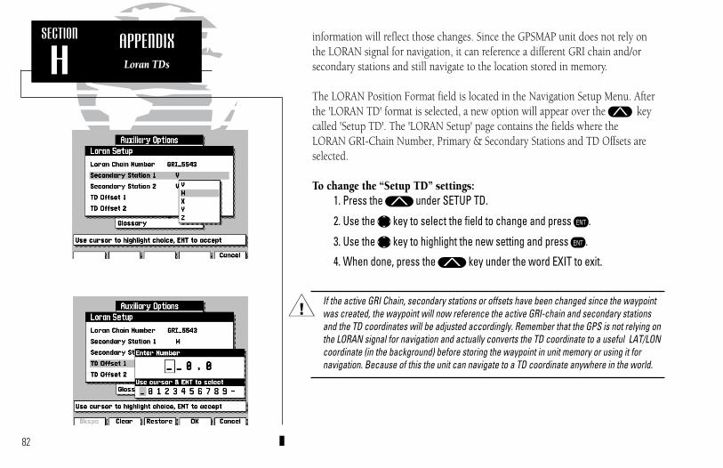
82
SECTION
HAPPENDIXLoran TDs
information will reflect those changes. Since the GPSMAP unit does not rely onthe LORAN signal for navigation, it can reference a different GRI chain and/or secondary stations and still navigate to the location stored in memory.
The LORAN Position Format field is located in the Navigation Setup Menu. Afterthe 'LORAN TD' format is selected, a new option will appear over the M keycalled 'Setup TD'. The 'LORAN Setup' page contains the fields where the LORAN GRI-Chain Number, Primary & Secondary Stations and TD Offsets areselected.
To change the “Setup TD” settings:1. Press the M under SETUP TD.
2. Use the K key to select the field to change and press C.
3. Use the K key to highlight the new setting and press C.
4. When done, press the M key under the word EXIT to exit.
If the active GRI Chain, secondary stations or offsets have been changed since the waypoint was created, the waypoint will now reference the active GRI-chain and secondary stations and the TD coordinates will be adjusted accordingly. Remember that the GPS is not relying onthe LORAN signal for navigation and actually converts the TD coordinate to a useful LAT/LONcoordinate (in the background) before storing the waypoint in unit memory or using it for navigation. Because of this the unit can navigate to a TD coordinate anywhere in the world.
I
215225manb.qxd 4/27/00 9:22 AM Page 82

AActivating Routes........................................39Active Route ..................................11, 27, 37Active Route Page .................................11, 27Active Waypoints ...........................25, 27, 37Alarm Setup................................................51Anchor Alarm.............................................51Antenna Installation ..............................66-67Arrival Alarm..............................................51Auxiliary Menu .................................2, 46-61
BBacklight Level .............................................1Beacon Receiver Setup.....................52-54, 67Beacon Status ........................................15-16Bearing .......................................................79Bearing Pointer ...........................................26Boat Icon ....................................................17Boat Mode ..................................................18Built-in Map Coverage ................................76
CCalibrations, Map .......................................24Cancelling Active Routes ............................39Cancelling Active GOTOs...........................36Capabilities .................................................viiCautions .......................................................iiClock Alarm ...............................................51Configurations, GPSMAP Unit...............46-61Configurations, Map..............................23-24Contrast Setting..........................................48Countdown/Elapsed Timers .......................51Creating Routes ....................................38, 45Creating Waypoints..............................28, 32
Cross Track Error .......................................79CTR Key ..........................................viii, 6, 19Cursor Mode ..............................................18Cursor Movement...................................6, 19
DData Entry ..............................................3, 47DATA Key ......................viii, 4, 10-11, 22, 25Data Window .........................................4, 21Date/Time Formats .....................................48Datums ...........................................50, 76-78Definitions ......................................59, 79-80Desired Track (DTK) ..................................79Depth Contours ..............................23-24, 49Depth Units ................................................49Deleting Routes ..........................................39Deleting Waypoints...............................30-31DGPS Setup.....................................52-54, 67DGPS Status ..........................................15-16
EEditing Routes by Text ..........................43-44Editing Routes Graphically ....................40-42Editing Waypoints by Text .........................31Editing Waypoints Graphically..............29-30Elapsed Timer ............................................51ENT Key.....................................viii, 3, 46-47Entering Initial Position ..............................16Estimated Time of Arrival (ETA).................79Estimated Time Enroute (ETE) ...................79
FFull Screen Mapping...................................22
83
INDEX
215225manb.qxd 4/27/00 9:22 AM Page 83

GG-chart Cartridges.................................62-64Glossary ..........................................59, 79-80GOTO Key ...............................viii, 12, 35-36Grid Coordinates ........................................49Ground Speed............................................79
HHeading Selection.......................................49Highway Page........................................25-26Highway Scale ............................................26
IInstallation ............................................65-69Interface Formats........................................80Interface Setup ......................................52-55Interval, track storage .................................59Inverting Routes .........................................39
KKeypad Usage ............................................viiiKeypad Tone ..............................................48
LLand Data ...................................................23Local Time Offset .......................................48LORAN TDs .........................49, 81-82
MMagnetic Variation......................................49Man Overboard Function (MOB)................36Map Calibration..........................................24Map Configuration ................................23-24Map Datum List ....................................76-78
Map Datum Selection .................................50Map Display .................................................4Map Orientation .........................................50Map Page...............................................17-24Map Scales..................................................20MAPS Key......................................viii, 11, 63Marine Data................................................23MARK Key .......................................viii, 7, 34Marking Positions...................................7, 34MENU Key ......................................viii, 4, 22Menu Options .......................................46-47Menu Selection......................................46-47Messages...............................................12, 61Message Descriptions ............................72-74MOB Key .............................................viii, 36Modifying Routes ..................................40-44Modifying Waypoints............................29-30Moving Waypoints ...............................30, 40
NNavigation Setup ........................................49Navigation Units.........................................49Nearest Waypoint List ................................33NMEA Formats...........................................70NMEA Setup .........................................54-55No Map Mode ......................................11, 20Normal Mode .............................................48
OOff Course Alarm .......................................51Offset, local time ..................................48, 73Operation Setup .........................................48Overzoom Mode...................................11, 20
84
INDEX
215225manb.qxd 4/27/00 9:22 AM Page 84

PPacking List .................................................ivPAGE Key ..................................................viiiPhysical Specifications ................................71Point-to-Point Planning ..............................58Port Services Information ...........................64Position Entry.........................................3, 16Position Format ..........................................49Power/Data Cable .......................................69Power Off ............................................viii, 13Power On ..............................................viii, 1Proximity Alarm .........................................51Proximity Waypoints List ...........................56
RRange/Bearing Calculations.........................22Reference Waypoints ..................................33Removing G-chart Cartridges .....................62Removing Route Waypoints .................42, 44Removing Waypoints ............................30-31Renaming Waypoints............................29, 44Resolution, Track Plot ................................59Reviewing Routes ...........................40, 43, 45Reviewing Waypoints .................................29Routes ...............................................8, 37-45Route Comments........................................42Route Planning Mode .................................57
SSatellite Acquisition ..............................15, 16Signal Strength Bars....................................15Simulator Mode......................................2, 48Simulator Tour........................................1-13
Sky View (Satellite).....................................15Softkeys ........................................................2Softkey Menu .........................................5, 22Satellite Status Page ...........................2, 15-16Sunrise/Sunset Calculation .........................58
TTarget Cursor .........................................6, 18Text Entry ..............................................3, 47Time Offsets .........................................48, 75Timer/Alarm Setup .....................................51Tone Selection ............................................48TracBack Routes .........................................58Track Memory ............................................59Track Plot...................................................59Track Recording .........................................59Turn (TRN) ................................................80
UUnits of Measure.........................................49UTC time....................................................48UTM/UPS Coordinates .........................49, 80
VVelocity Made Good (VMG) .......................80
WWarranty & Registration..............................iiiWaypoints.............................................28-33Waypoints List ......................................30-31Waypoints, Nearest ....................................33Wiring Installation................................67, 69
ZZOOM Key ....................................viii, 20, 26 85
INDEX
215225manb.qxd 4/27/00 9:22 AM Page 85

215225manb.qxd 4/27/00 9:22 AM Page 86

215225manb.qxd 4/27/00 9:22 AM Page 87

®
© 1998-2000 GARMIN Corporation
1200 E. 151st Street, Olathe, KS 66062 U.S.A.
Web Site Address: www.garmin.com
GARMIN (Europe) Ltd., Unit 5, The Quadrangle, Abbey Park, Romsey, Hampshire SO51 9AQ U.K.
Garmin (Asia) Corp., No. 68, Jangshu 2nd Rd., Shijr, Taipei County, Taiwan
Part Number 190-00061-20 Rev. B
215225manb.qxd 4/27/00 9:22 AM Page 88