Embed Size (px)
Citation preview

Your source for quality GNSS Networking Solutions and Design Services, Now!
Document Description: GPSRKXL1 Data Sheet Document Number:
Author: Phillip Coiner Department:
GPSRK
Features
• L1 Filtering for interference rejection • High Gain G = 40dB • Low Noise Figure F < 2.2dB
Description
Designed for use as a gain block in a GPS distribution network GPSRKXL1 features L1 filtering, low The product may be powered externally with be powered by a GPS receiver’s antenna voltage output. GPSRKXL1 can provide a DC voltage The GPSRKXL1 amplifier comes with many available options to meet your specific needs. Please call, fax, email ([email protected] on product options, specifications
Page 1 of GNSS Networking Solutions and Design Services, Now!
Document Number: 059-FAF-ACB-AAS-YYZ Revision: 002 Department: R&D Date: 03 June 2010
GPSRKXL1 Amplifier Technical Product Data
rejection
as a gain block in a GPS distribution network where high gain low noise figure and 40dB of gain.
may be powered externally with an AC input voltage option, a DC input option, oriver’s antenna voltage output. With the source voltage option
can provide a DC voltage output to power an active GPS antenna. comes with many available options to meet your specific needs. Please
rce.com), or visit our website (www.gpssource.cominformation on product options, specifications.
of 7
2010
is required, the
DC input option, or it may oltage option the
. comes with many available options to meet your specific needs. Please
www.gpssource.com) for further
Your source for quality GNSS Networking Solutions and Design Services, Now!
Document Description: GPSRKXL1 Data Sheet Document Number:
Author: Phillip Coiner Department:
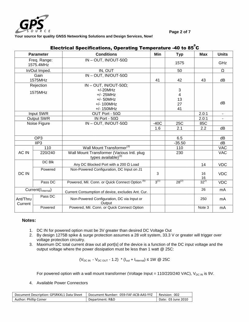
Electrical Specifications, Operating Temperature
Parameter Freq. Range: 1575.4MHz
IN –
In/Out Imped. Gain
1575MHz IN –
Rejection
1575MHz
IN –
Input SWR OUTOutput SWR Noise Figure IN –
OP3 IIP3
AC IN 110 Wall Mount Transformer
220/240 Wall Mount Transformer (Vartypes available)
DC IN
DC Blk Any DC Blocked Port with
Powered Non-Powered Configuration, DC Input on
Pass DC Powered, Mil. Conn. or Quick Connect Option
Current(Iinternal) Current Consumption of device, excludes Ant. Cur.
Ant/Thru Current
Pass DC Non-Powered
Powered Powered, Mil. Conn. or Quick Connect Option
Notes:
1. DC IN for powered option must be 3V greater than desired DC Voltage Out2. By design 1275B spike & surge protection assumes a 28 volt system, 33.3 V or greater will trigger over
voltage protection circuitry. 3. Maximum DC total current draw out all port[s] of the device is a funct
output voltage where the power dissipation must be less than 1 watt @ 25C:
(VDC IN -
For powered option with a wall mount transformer (Voltage Input = 110/220/240 VAC),
4. Available Power Connectors
Page 2 of GNSS Networking Solutions and Design Services, Now!
Document Number: 059-FAF-ACB-AAS-YYZ Revision: 002 Department: R&D Date: 03 June 2010
Electrical Specifications, Operating Temperature -40 to 85
Conditions Min Typ OUT, IN/OUT-50Ω
1575
IN, OUT 50 OUT, IN/OUT-50Ω
41
42 OUT, IN/OUT-50Ω;
+/-20MHz +/- 25MHz +/- 50MHz +/- 100MHz +/- 150MHz
3 4
13 27 41
OUT Port - 50Ω IN Port - 50Ω
OUT, IN/OUT-50Ω -40C 25C 1.6 2.1
6.5 -35.50
Wall Mount Transformer(3) 110 Wall Mount Transformer (Various Intl. plug
types available)(3) 230
DC Blocked Port with a 200 Ω Load Powered Configuration, DC Input on J1
3
Powered, Mil. Conn. or Quick Connect Option (5) 3(1) 28(2)
Current Consumption of device, excludes Ant. Cur.
Powered Configuration, DC via Input or Output
Powered, Mil. Conn. or Quick Connect Option
ption must be 3V greater than desired DC Voltage Out By design 1275B spike & surge protection assumes a 28 volt system, 33.3 V or greater will trigger over
Maximum DC total current draw out all port[s] of the device is a function of the DC input voltage and the output voltage where the power dissipation must be less than 1 watt @ 25C:
- VDC OUT - 1.2) * (Iout + Iinternal) ≤ 1W @ 25C
For powered option with a wall mount transformer (Voltage Input = 110/220/240 VAC),
of 7
2010
40 to 850C
Max Units
GHz
Ω
43
dB
dB
2.0:1 - 2.0:1 - 85C 2.2 dB
dB
dB VAC VAC
14 VDC
16 16
VDC
322) VDC
26 mA
250 mA
Note 3 mA
By design 1275B spike & surge protection assumes a 28 volt system, 33.3 V or greater will trigger over
ion of the DC input voltage and the
For powered option with a wall mount transformer (Voltage Input = 110/220/240 VAC), VDC IN is 9V.
Your source for quality GNSS Networking Solutions and Design Services, Now!
Document Description: GPSRKXL1 Data Sheet Document Number:
Author: Phillip Coiner Department:
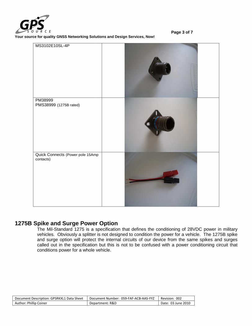
MS3102E10SL-4P
PM38999 PMS38999 (1275B rated)
Quick Connects (Power pole 15Amp contacts)
1275B Spike and Surge Power Option
The Mil-Standard 1275 is a specification that defines the conditioning of 2vehicles. Obviously a splitter is not designed to condition the power for a vehicle. The 1275B spike and surge option will protect the internal circuits of our device from the same spikes and surges called out in the specification conditions power for a whole vehicle.
Page 3 of GNSS Networking Solutions and Design Services, Now!
Document Number: 059-FAF-ACB-AAS-YYZ Revision: 002 Department: R&D Date: 03 June 2010
(Power pole 15Amp
1275B Spike and Surge Power Option Standard 1275 is a specification that defines the conditioning of 2
vehicles. Obviously a splitter is not designed to condition the power for a vehicle. The 1275B spike and surge option will protect the internal circuits of our device from the same spikes and surges called out in the specification but this is not to be confused with a power conditioning circuit that conditions power for a whole vehicle.
of 7
2010
Standard 1275 is a specification that defines the conditioning of 28VDC power in military vehicles. Obviously a splitter is not designed to condition the power for a vehicle. The 1275B spike and surge option will protect the internal circuits of our device from the same spikes and surges
but this is not to be confused with a power conditioning circuit that
Your source for quality GNSS Networking Solutions and Design Services, Now!
Document Description: GPSRKXL1 Data Sheet Document Number:
Author: Phillip Coiner Department:
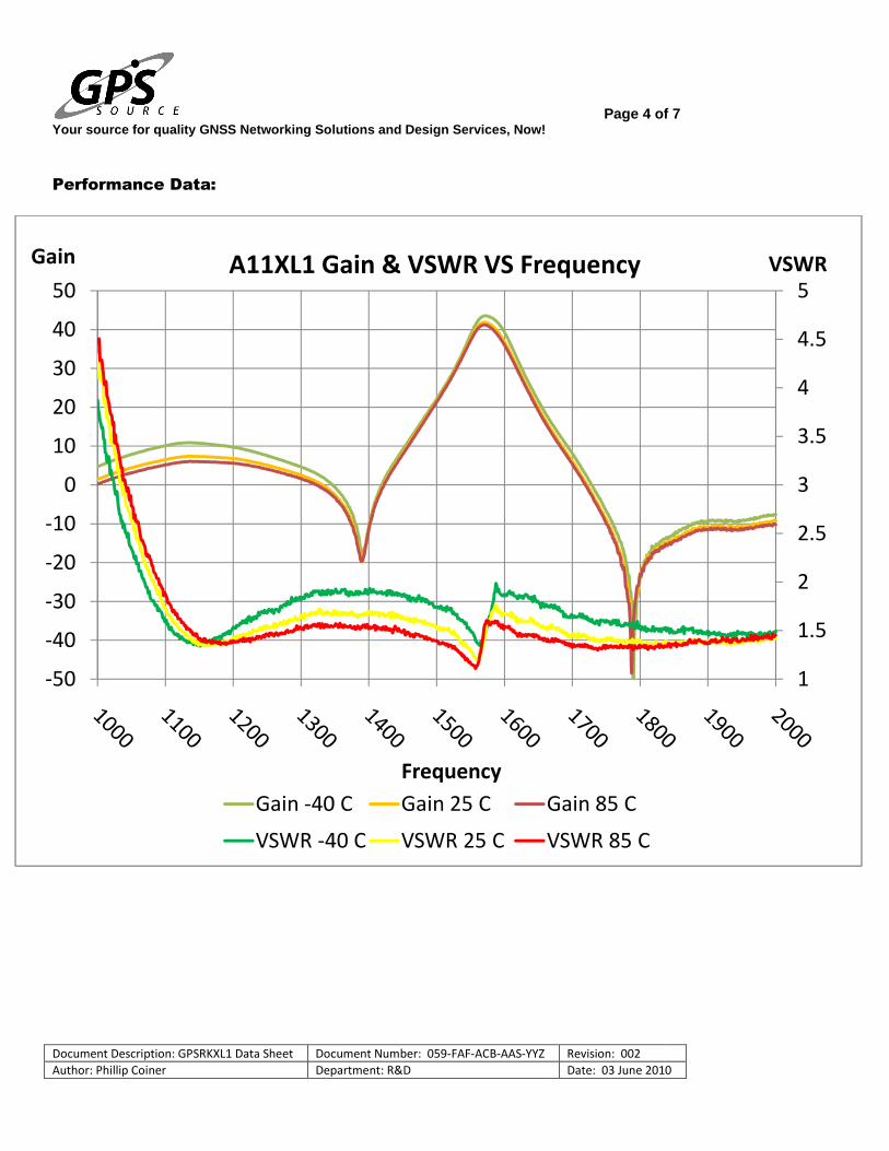
Performance Data:
-50
-40
-30
-20
-10
0
10
20
30
40
50
Gain A11XL1 Gain & VSWR VS Frequency
Gain -40 C
VSWR -40 C
Page 4 of GNSS Networking Solutions and Design Services, Now!
Document Number: 059-FAF-ACB-AAS-YYZ Revision: 002 Department: R&D Date: 03 June 2010
Frequency
A11XL1 Gain & VSWR VS Frequency
40 C Gain 25 C Gain 85 C
40 C VSWR 25 C VSWR 85 C
of 7
2010
1
1.5
2
2.5
3
3.5
4
4.5
5
VSWR
Your source for quality GNSS Networking Solutions and Design Services, Now!
Document Description: GPSRKXL1 Data Sheet Document Number:
Author: Phillip Coiner Department:
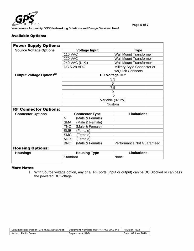
Available Options:
Power Supply Options:
Source Voltage Options 110 VAC220 VAC240 VAC (U.K.)DC 5-
Output Voltage Options(1)
RF Connector Options:
Connector Options N (Male & Female)SMA (Male & Female)TNC (Male & Female)SMB (Female)SMC (Female)MCX (Female)BNC (Male & Female)
Housing Options: Housings
Standard
More Notes: 1. With Source voltage option, any or all RF ports (input or output) can be DC Blocked or can pass
the powered DC voltage
Page 5 of GNSS Networking Solutions and Design Services, Now!
Document Number: 059-FAF-ACB-AAS-YYZ Revision: 002 Department: R&D Date: 03 June 2010
Voltage Input Type 110 VAC Wall Mount Transformer
0 VAC Wall Mount Transformer240 VAC (U.K.) Wall Mount Transformer
-28 VDC Military Style Connector or w/Quick Connects
DC Voltage Out
3.3 5
7.5 9 12
Variable (3-12V) Custom
Connector Type LimitationsN (Male & Female) SMA (Male & Female) TNC (Male & Female) SMB (Female) SMC (Female) MCX (Female) BNC (Male & Female) Performance Not Guaranteed
Housing Type LimitationsStandard None
With Source voltage option, any or all RF ports (input or output) can be DC Blocked or can pass
of 7
2010
Wall Mount Transformer Wall Mount Transformer Wall Mount Transformer Military Style Connector or
Limitations
Performance Not Guaranteed
Limitations
With Source voltage option, any or all RF ports (input or output) can be DC Blocked or can pass

Your source for quality GNSS Networking Solutions and Design Services, Now!
Document Description: GPSRKXL1 Data Sheet Document Number:
Author: Phillip Coiner Department:
Part Number:
Product: GPSRKXL1 Gain Option: XX – Custom Gain Housing Option: W – Water Proof
Source Voltage: P110 – Transformer, P220 – Transformer, P240 – Transformer, PDC – DC w/Quick Connects PM – Military Connector (User supplies DC) Output Voltage: 3.3, 5, 7.5, 9, 12, XX, V – Denotes Output Voltage (XX – custom output voltage, V Connector Options: NM – N, Male NF – N, Female SM – SMA, Male SF – SMA, Female TM – TNC, Male TF – TNC, Female BM – BNC, Male BF – BNC, Female SB – SMB Jack, Female SC – SMC Jack, Female MX – MCX Jack, Female
Page 6 of GNSS Networking Solutions and Design Services, Now!
Document Number: 059-FAF-ACB-AAS-YYZ Revision: 002 Department: R&D Date: 03 June 2010
GPSRKXL1 –XX –W – P110 / 5
Military Connector (User supplies DC)
Denotes Output Voltage custom output voltage, V – variable)
of 7
2010
– NF-NM
Your source for quality GNSS Networking Solutions and Design Services, Now!
Document Description: GPSRKXL1 Data Sheet Document Number:
Author: Phillip Coiner Department:
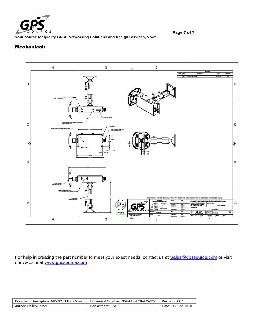
Mechanical:
For help in creating the part number to meet your exact needs, contact us at our website at www.gpssource.com
Page 7 of GNSS Networking Solutions and Design Services, Now!
Document Number: 059-FAF-ACB-AAS-YYZ Revision: 002 Department: R&D Date: 03 June 2010
meet your exact needs, contact us at [email protected]
of 7
2010
[email protected] or visit