Embed Size (px)
Citation preview

Grades of Reinforcing Steel
1

Grades of Reinforcing Steel
Reinforcing bars may be rolled from billet steel, axle steel, or rail
steel. Only occasionally, however, are they rolled from old train rails or
locomotive axles. These latter steels have been cold-worked for many years
and are not as ductile as the billet steels.
2
There are several types of reinforcing bars, designated by the
ASTM, which are listed after this paragraph. These steels are available in
different grades as Grade 50, Grade 60, and so on, where Grade 50 means
the steel has a specified yield point of 50,000 psi, Grade 60 means 60,000
psi, and so on.

Grades of Reinforcing Steel
3
1. ASTM A615: Deformed and plain billet steel bars. These bars, which
must be marked with the letter S (for type of steel), are the most
widely used reinforcing bars in the United States. Bars are of four
minimum yield strength levels: 40,000 psi (280 MPa); 60,000 psi
(420 MPa); 75,000 psi (520 MPa); and 80,000 psi (550 MPa).
2. ASTM A706: Low-alloy deformed and plain bars. These bars, which
must be marked with the letter W (for type of steel), are to be used
where controlled tensile properties and/or specially controlled
chemical composition is required for welding purposes. They are
available in two grades: 60,000 psi (420 MPa) and 80,000 psi (550
MPa), designated as Grade 60 (420) and Grade 80 (550),
respectively.
Grades of Reinforcing Steel
4
3. ASTM A996: Deformed rail steel or axle steel bars. They must be
marked with the letter R (for type of steel).
4. When deformed bars are produced to meet both the A615 and
A706 specifications, they must be marked with both the letters S
and W.
Grades of Reinforcing Steel
5
Almost all reinforcing bars conform to the A615 specification. Bars
conforming to the A706 specification are intended for certain uses when
welding and/or bending are of particular importance. Bars conforming to
this specification may not always be available from local suppliers.
There is only a small difference between the prices of reinforcing
steel with yield strengths of 40 ksi and 60 ksi. As a result, the 60-ksi bars are
the most commonly used in reinforced concrete design. When bars are
made from steels with fy of 60 ksi or more, the ACI (Section 3.5.3.2) states
that the specified yield strength must be the stress corresponding to a strain
of 0.35%.
Grades of Reinforcing Steel
6
For bars with fy less than 60 ksi, the yield strength shall be taken as
the stress corresponding to a strain of 0.5%. The ACI (Section 9.4) has
established an upper limit of 80 ksi on yield strengths permitted for design
calculations for reinforced concrete. If the ACI were to permit the use of
steels with yield strengths greater than 80 ksi, it would have to provide
other design restrictions, since the yield strain of 80 ksi steel is almost equal
to the ultimate concrete strain in compression. (This last sentence will make
sense after the reader has studied Chapter 2.)
There has been gradually increasing demand through the years for
Grade 75 and Grade 80 steel, particularly for use in high-rise buildings,
where it is used in combination with high strength concretes. The results are
smaller columns, more rentable floor space, and smaller foundations for the
resulting lighter buildings.

Grades of Reinforcing Steel
7
Grade 75 and Grade 80 steel are appreciably higher in cost, and the
#14 and #18 bars are often unavailable from stock and will probably have to
be specially ordered from the steel mills. This means that there may have to
be a special rolling to supply the steel. As a result, its use may not be
economically justified unless at least 50 or 60 tons are ordered.
The modulus of elasticity for non-prestressed steels is considered
to be equal to 29 × 10⁶ psi. For prestressed steels, it varies somewhat from
manufacturer to manufacturer, with a value of 27 × 10⁶ psi being fairly
common.
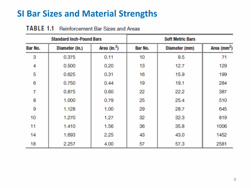
SI Bar Sizes and Material Strengths
8

Corrosive Environments
9
Corrosive Environments When reinforced concrete is subjected to deicing salts, seawater, or
spray from these substances, it is necessary to provide special corrosion
protection for the reinforcing. The structures usually involved are bridge
decks, parking garages, wastewater treatment plants, and various coastal
structures. We must also consider structures subjected to occasional
chemical spills that involve chlorides.
10
Should the reinforcement be insufficiently protected, it will
corrode; as it corrodes, the resulting oxides occupy a volume far greater
than that of the original metal. The results are large outward pressures that
can lead to severe cracking and spalling of the concrete. This reduces the
concrete protection, or cover, for the steel, and corrosion accelerates. Also,
the bond, or sticking of the concrete to the steel, is reduced. The result of all
of these factors is a decided reduction in the life of the structure.

Corrosive Environments Section 7.7.6 of the code requires that for corrosive environments,
more concrete cover must be provided for the reinforcing; it also requires
that special concrete proportions or mixes be used.
11
The lives of such structures can be greatly increased if epoxy-
coated reinforcing bars are used. Such bars need to be handled very
carefully so as not to break off any of the coating. Furthermore, they do not
bond as well to the concrete, and their embedment lengths will have to be
increased somewhat for that reason, as you will learn in Chapter 7. A new
type of bar coating, a dual coating of a zinc alloy and an epoxy coating, was
introduced in the 2011 ACI 318 Code. Use of stainless steel reinforcing, as
described in Section 1.14, can also significantly increase the service life of
structures exposed to corrosive environments.
Identifying Marks on Reinforcing Bars
12
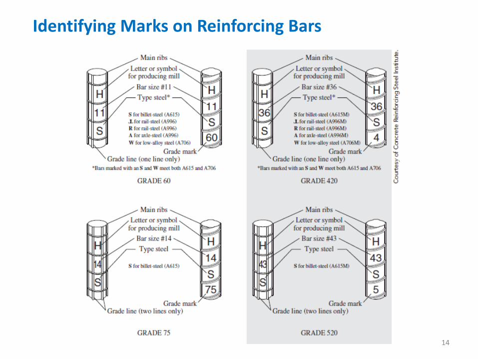
Identifying Marks on Reinforcing Bars
It is essential for people in the shop and the field to be able to
identify at a glance the sizes and grades of reinforcing bars. If they are not
able to do this, smaller and lower-grade bars other than those intended by
the designer may be used. To prevent such mistakes, deformed bars have
rolled-in identification markings on their surfaces. These markings are
described in the following list and are illustrated in Figure 1.4.
13
1. The producing company is identified with a letter.
2. The bar size number (3 to 18) is given next.
3. Another letter is shown to identify the type of steel (S for billet, R in
addition to a rail sign for rail steel, A for axle, and W for low alloy).
Identifying Marks on Reinforcing Bars
14
Identifying Marks on Reinforcing Bars
15
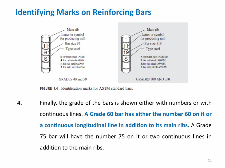
4. Finally, the grade of the bars is shown either with numbers or with
continuous lines. A Grade 60 bar has either the number 60 on it or
a continuous longitudinal line in addition to its main ribs. A Grade
75 bar will have the number 75 on it or two continuous lines in
addition to the main ribs.

Introduction to Loads
16

Introduction to Loads
17
Perhaps the most important and most difficult task faced by the
structural designer is the accurate estimation of the loads that may be
applied to a structure during its life. No loads that may reasonably be
expected to occur may be overlooked. After loads are estimated, the next
problem is to decide the worst possible combinations of these loads that
might occur at one time. For instance, would a highway bridge completely
covered with ice and snow be simultaneously subjected to fast-moving lines
of heavily loaded trailer trucks in every lane and to a 90-mile lateral wind, or
is some lesser combination of these loads more reasonable?

Introduction to Loads
18
The next few sections of this chapter provide a brief introduction to
the types of loads with which the structural designer must be familiar. The
purpose of these sections is not to discuss loads in great detail but rather to
give the reader a feel for the subject. As will be seen, loads are classed as
being dead, live, or environmental.

Dead Loads
19

Dead Loads
20
Dead loads are loads of constant magnitude that remain in one
position. They include the weight of the structure under consideration as
well as any fixtures that are permanently attached to it. For a reinforced
concrete building, some dead loads are the frames, walls, floors, ceilings,
stairways, roofs, and plumbing.
To design a structure, it is necessary for the weights or dead loads
of the various parts to be estimated for use in the analysis. The exact sizes
and weights of the parts are not known until the structural analysis is made
and the members of the structure are selected. The weights, as determined
from the actual design, must be compared with the estimated weights. If
large discrepancies are present, it will be necessary to repeat the analysis
and design using better estimated weights.

Dead Loads
21
Reasonable estimates of structure weights may be obtained by
referring to similar structures or to various formulas and tables available in
most civil engineering handbooks. An experienced designer can estimate
very closely the weights of most structures and will spend little time
repeating designs because of poor estimates.
The approximate weights of some common materials used for
floors, walls, roofs, and the like are given in Table 1.2.

Live Loads
22
Live Loads
23
Live loads are loads that can change in magnitude and position.
They include occupancy loads, warehouse materials, construction loads,
overhead service cranes, equipment operating loads, and many others. In
general, they are induced by gravity.
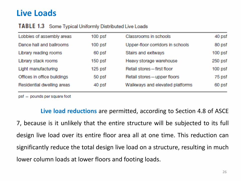
Some typical floor live loads that act on building structures are
presented in Table 1.3. These loads, which are taken from Table 4-1 in ASCE
7-10, act downward and are distributed uniformly over an entire floor. By
contrast, roof live loads are 20 psf (pounds per square feet) maximum
distributed uniformly over the entire roof.
Among the many other types of live loads are:
Traffic loads for bridges—Bridges are subjected to series of concentrated
loads of varying magnitude caused by groups of truck or train wheels.
Live Loads
24
Impact loads—Impact loads are caused by the vibration of moving or
movable loads. It is obvious that a crate dropped on the floor of a
warehouse or a truck bouncing on uneven pavement of a bridge causes
greater forces than would occur if the loads were applied gently and
gradually. Impact loads are equal to the difference between the magnitude
of the loads actually caused and the magnitude of the loads had they been
dead loads.
Longitudinal loads—Longitudinal loads also need to be considered in
designing some structures. Stopping a train on a railroad bridge or a truck
on a highway bridge causes longitudinal forces to be applied. It is not
difficult to imagine the tremendous longitudinal force developed when the
driver of a 40-ton trailer truck traveling at 60 mph suddenly has to apply the

Live Loads
25
Miscellaneous loads—Among the other types of live loads with which the
structural designer will have to contend are soil pressures (such as the
exertion of lateral earth pressures on walls or upward pressures on
foundations), hydrostatic pressures (such as water pressure on dams, inertia
forces of large bodies of water during earthquakes, and uplift pressures on
tanks and basement structures), blast loads (caused by explosions, sonic
booms, and military weapons), and centrifugal forces (such as those caused
on curved bridges by trucks and trains or similar effects on roller coasters).
brakes while crossing a highway bridge. There are other longitudinal load
situations, such as ships running into docks and the movement of traveling
cranes that are supported by building frames.
Live Loads
26
Live load reductions are permitted, according to Section 4.8 of ASCE
7, because is it unlikely that the entire structure will be subjected to its full
design live load over its entire floor area all at one time. This reduction can
significantly reduce the total design live load on a structure, resulting in much
lower column loads at lower floors and footing loads.

Live Loads
27

Environmental Loads
28

Environmental Loads
29
Environmental loads are loads caused by the environment in which
the structure is located. For buildings, they are caused by rain, snow, wind,
temperature change, and earthquake. Strictly speaking, these are also live
loads, but they are the result of the environment in which the structure is
located. Although they do vary with time, they are not all caused by gravity
or operating conditions, as is typical with other live loads. In the next few
paragraphs, a few comments are made about the various kinds of
environmental loads.
1. Snow and ice. In the colder states, snow and ice loads are often
quite important. One inch of snow is equivalent to approximately
0.5 psf, but it may be higher at lower elevations where snow is
denser. For roof designs, snow loads of from 10 psf to 40 psf are

Environmental Loads
30
used, the magnitude depending primarily on the slope of the roof
and to a lesser degree on the character of the roof surface. The
larger values are used for flat roofs, the smaller ones for sloped
roofs. Snow tends to slide off sloped roofs, particularly those with
metal or slate surfaces. A load of approximately 10 psf might be
used for 45◦ slopes, and a 40-psf load might be used for flat roofs.
Snow is a variable load, which may cover an entire roof or only part of it.
Snow may slide off one roof and onto a lower one.

Environmental Loads
31
2. Rain. Although snow loads are a more severe problem than rain
loads for the usual roof, the situation may be reversed for flat
roofs—particularly those in warmer climates. If water on a flat roof
accumulates faster than it runs off, the result is called ponding
because the increased load causes the roof to deflect into a dish
shape that can hold more water, which causes greater deflections,
and so on. This process continues until equilibrium is reached or

Environmental Loads
32
3. Wind. A survey of engineering literature for the past 150 years
reveals many references to structural failures caused by wind.
Perhaps the most infamous of these have been bridge failures such
as those of the Tay Bridge in Scotland in 1879 (which caused the
deaths of 75 persons) and the Tacoma Narrows Bridge (Tacoma,
Washington) in 1940. There have also been some disastrous
building failures from wind during the same period, such as that of the
Union Carbide Building in Toronto in 1958. It is important to realize that a
large percentage of building failures from wind have occurred during the
buildings’ erection.
Environmental Loads
33
The magnitude and duration of wind loads vary with geographical locations,
the heights of structures above ground, the types of terrain around the
structures, the proximity of other buildings, the location with in the
structure, and the character of the wind itself.
Environmental Loads
34
The basic form of the equation presented in the specification is
In this equation, p is the estimated wind load (in psf) acting on the
structure. This wind load will vary with height above the ground and with
the location on the structure. The quantity, q, is the reference velocity
pressure. It varies with height and with exposure to the wind. The
aerodynamic shape factor, C, is dependent upon the shape and orientation
of the building with respect to the direction from which the wind is
blowing. Lastly, the gust response factor, G, is dependent upon the nature
of the wind and the location of the building. Other considerations in
determining design wind pressure include importance factor and surface
roughness.

Environmental Loads
35
4. Seismic loads. Many areas of the world are in earthquake territory,
and in those areas, it is necessary to consider seismic forces in
design for all types of structures. Through the centuries, there have
been catastrophic failures of buildings, bridges, and other
structures during earthquakes. It has been estimated that as many
as 50,000 people lost their lives in the 1988 earthquake in Armenia.
The 1989 Loma Prieta and 1994 Northridge earthquakes in
California caused many billions of dollars of property damage as
well as considerable loss of life. The 2008 earthquake in Sichuan
Province, China, caused 69,000 fatalities and another 18,000
missing.

Environmental Loads
36
Recent earthquakes have clearly shown that the average building or
bridge that has not been designed for earthquake forces can be destroyed by
an earthquake that is not particularly severe. Most structures can be
economically designed and constructed to withstand the forces caused
during most earthquakes. The cost of providing seismic resistance to existing
structures (called retrofitting), however, can be extremely high.
Some engineers seem to think that the seismic loads to be used in
design are merely percentage increases of the wind loads. This assumption
is incorrect, however, as seismic loads are different in their action and are
not proportional to the exposed area of the building but rather are
proportional to the distribution of the mass of the building above the
particular level being considered.

Environmental Loads
37
Another factor to be considered in seismic design is the soil
condition. Almost all of the structural damage and loss of life in the Loma
Prieta earthquake occurred in areas that have soft clay soils. Apparently
these soils amplified the motions of the underlying rock. It is well to
understand that earthquakes load structures in an indirect fashion. The
ground is displaced, and because the structures are connected to the
ground, they are also displaced and vibrated. As a result, various
deformations and stresses are caused throughout the structures.
From the preceding information, you can understand that no
external forces are applied aboveground by earthquakes to structures.

Selection of Design Loads
38
Selection of Design Loads
39
To assist the designer in estimating the magnitudes of live loads
with which he or she should proportion structures, various records have
been assembled through the years in the form of building codes and
specifications. These publications provide conservative estimates of live load
magnitudes for various situations. One of the most widely used design-load
specifications for buildings is that published by the American Society of Civil
Engineers (ASCE).
The designer is usually fairly well controlled in the design of live loads by the
building code requirements in his or her particular area. Unfortunately, the
values given in these various codes vary from city to city, and the designer
must be sure to meet the requirements of a particular locality. In the
absence of a governing code, the ASCE Code is an excellent one to follow.

Selection of Design Loads
40

Selection of Design Loads
41
Some other commonly used specifications are:
These specifications will on many occasions clearly prescribe the
loads for which structures are to be designed. Despite the availability of this
information, the designer’s ingenuity and knowledge of the situation are
often needed to predict what loads a particular structure will have to
support in years to come. Over the past several decades, insufficient
estimates of future traffic loads by bridge designers have resulted in a great
number of replacements with wider and stronger structures.
1. For railroad bridges, American Railway Engineering Association
(AREA).
2. For highway bridges, American Association of State Highway and
Transportation Officials (AASHTO).
3. For buildings, the International Building Code (IBC).