Embed Size (px)
Citation preview
Grading permit applications must be accompanied by drawings which graphically show the grading site and proposed grading changes. The completed application and attached plan pages must contain the following information for the permit application to be processed.
D Grading permit application (same form used for building permit application), filled out and signed
D Written statement of the intended purpose of the fill/excavation (for example, structural fill for building pad, retaining wall for landscaping yard, etc). This may be included on building permit application.
D Location (street address) of proposed grading work (this should be on grading permit application and each page of drawings
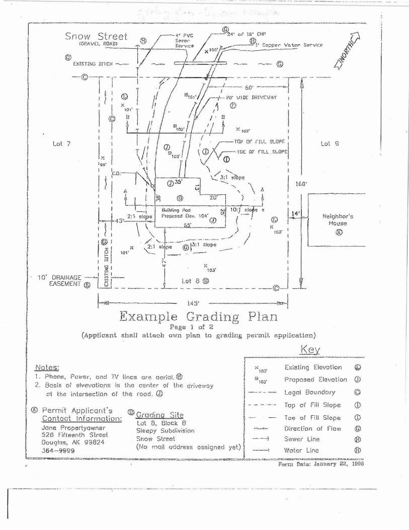
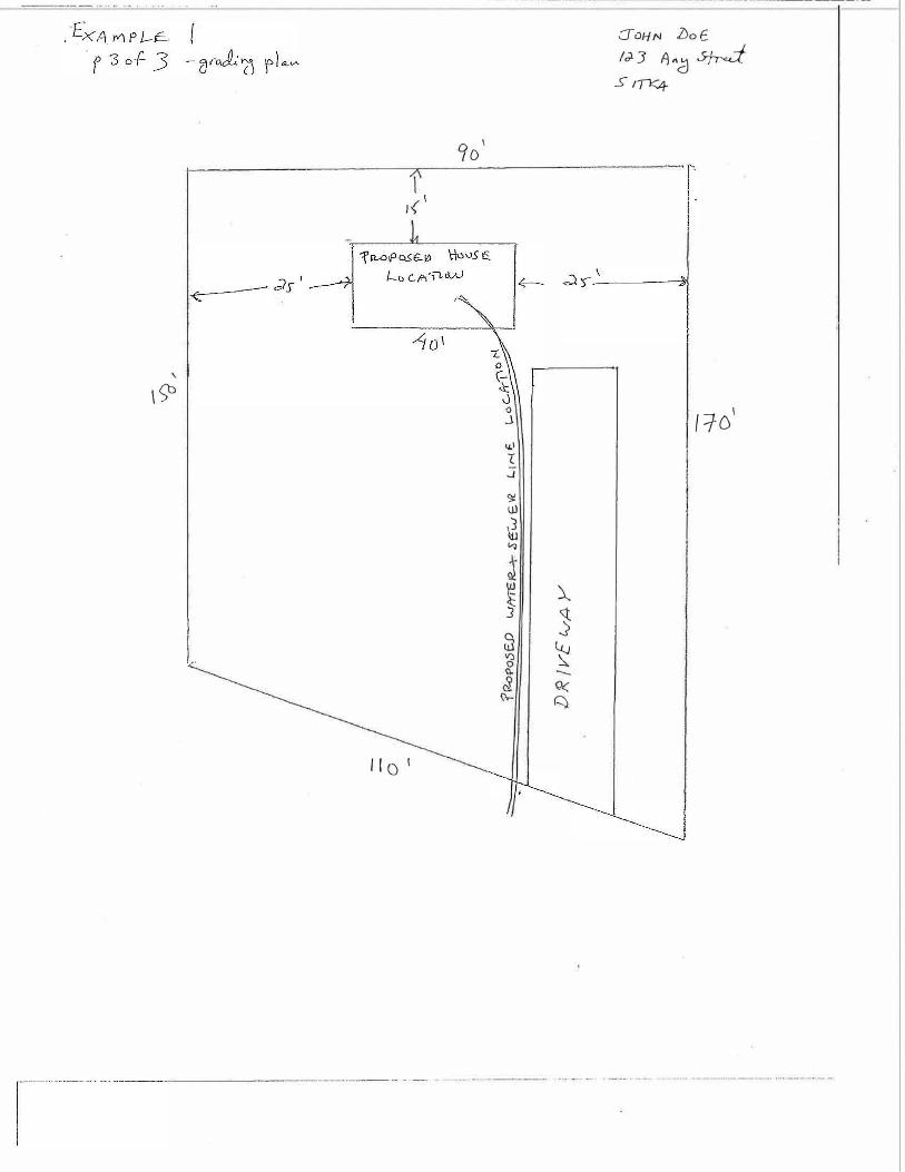
D Plan view (overhead birds-eye view) of site showing lot boundary lines and locations of proposed excavation and/or fill. Plan must show distance, in feet, of distance of toe of fill, or top of cutbank, to property lines.
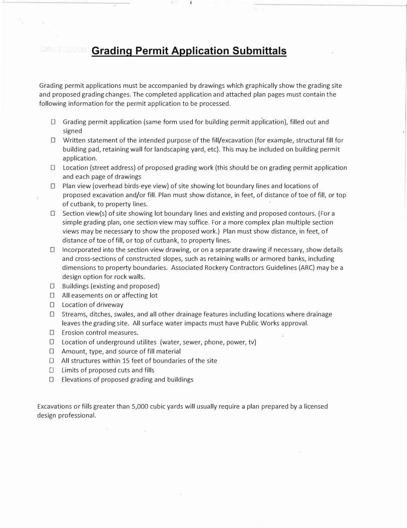
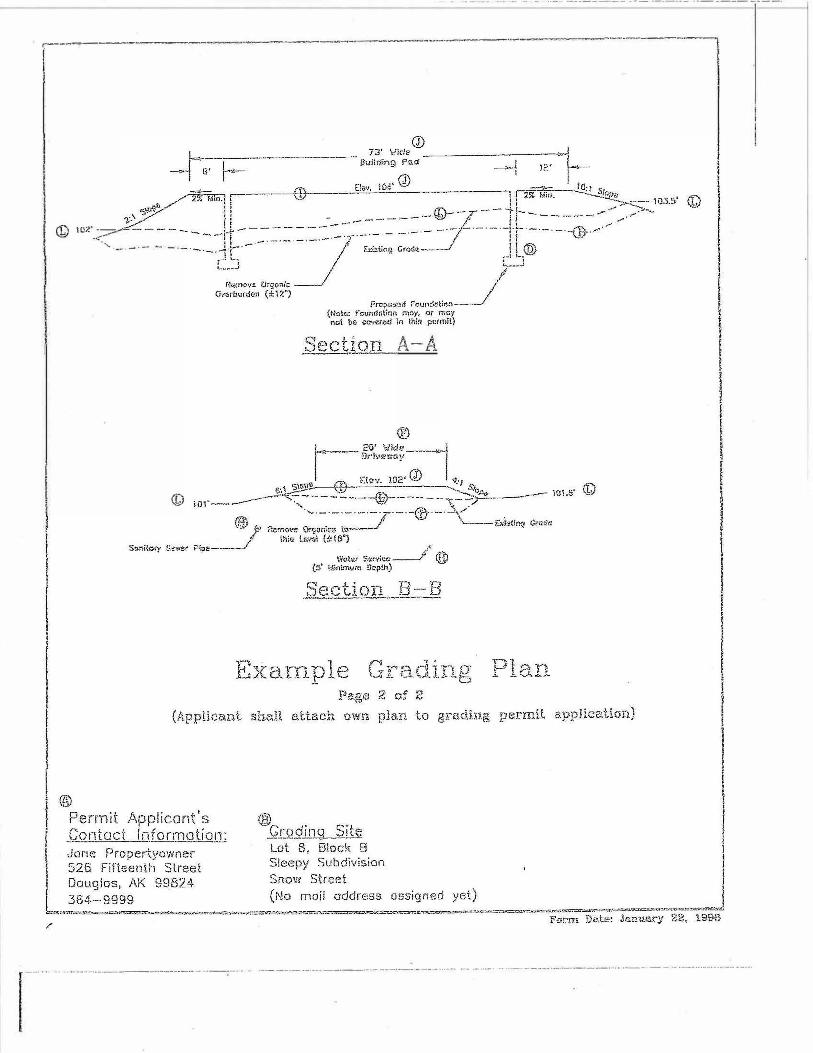
D Section view(s) of site showing lot boundary lines and existing and proposed contours. (For a simple grading plan, one section view may suffice. For a more complex plan multiple section views may be necessary to show the proposed work.) Plan must show distance, in feet, of distance of toe of fill, or top of cutbank, to property lines.
D Incorporated into the section view drawing, or on a separate drawing if necessary, show details and cross-sections of constructed slopes, such as retaining walls or armored banks, including dimensions to property boundaries. Associated Rockery Contractors Guidelines (ARC) may be a design option for rock walls.
D Buildings.(existing and proposed) D All easements on or affecting lot D Location of driveway D Streams, ditches, swales, and all other drainage features including locations where drainage
leaves the grading site. All surface water impacts must have Public Works approval. D Erosion control measures. D Location of underground utilites (water, sewer, phone, power, tv) D Amount, type, and source of fill material D All structures within 15 feet of boundaries of the site
D Limits of proposed cuts and fills D Elevations of proposed grading and buildings
Excavations or fills greater than 5,000 cubic yards will usually require a plan prepared by a licensed design professional.
Grading Permit Application Submittals
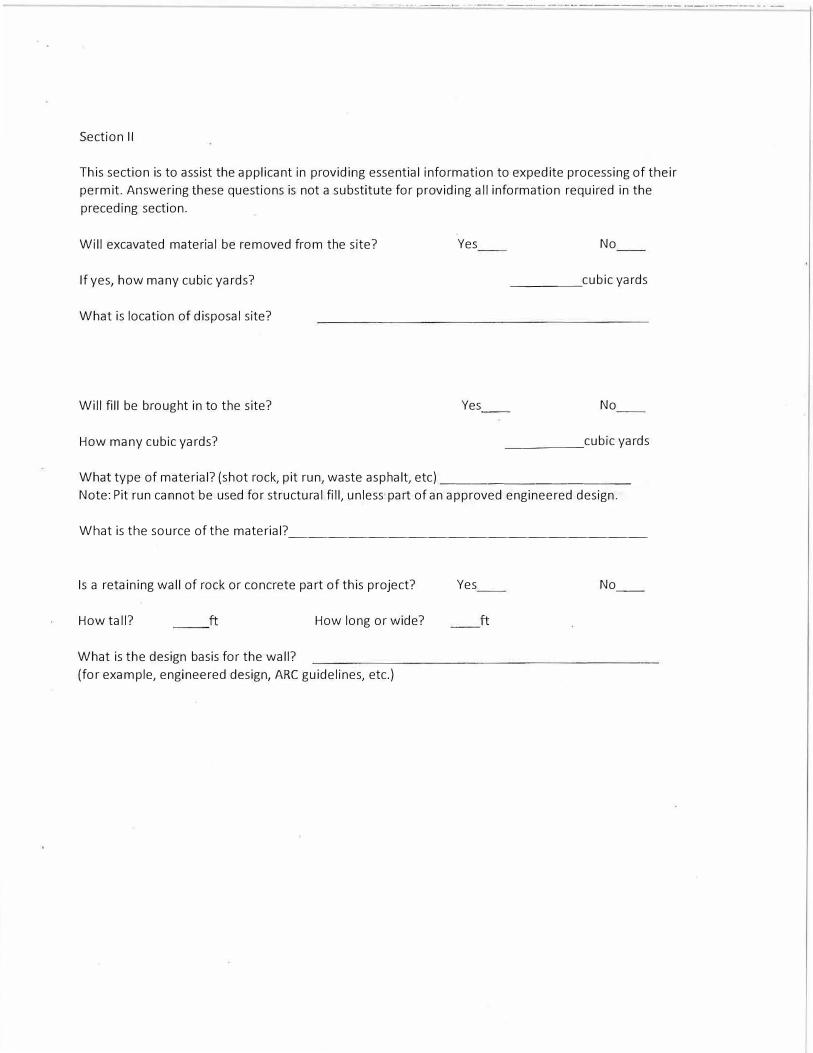
Section II
This section is to assist the applicant in providing essential information to expedite processing of their
permit. Answering these questions is not a substitute for providing all information required in the
preceding section.
Will excavated material be removed from the site?
If yes, how many cubic yards?
What is location of disposal site?
Will fill be brought in to the site?
How many cubic yards?
Yes
Yes
No
_____ cubic yards
No
_____ cubic yards
What type of material? (shot rock, pit run, waste asphalt, etc) ____________
Note: Pit run cannot be used for structural fill, unless part of an approved engineered design.
What is the source of the material?__________________
Is a retaining wall of rock or concrete part of this project? Yes No_._
How tall? ft How long or wide? ft
What is the design basis for the wall?
(for example, engineered design, ARC guidelines, etc.)
,-----------�----- --- ----·----·--�
© <:::novv Street ;---<!· ?\JC r--24· of' 18� CMP )\ ...., '@/ Sene1< } ® V
1
I I l ! r
I t
I I
1 I
I ll I l !
£GRAVEL P:�-------f---; / Serv,i.:e , :.....----· !' Co�per �,- Se,-vict-�
© 1 ;-
1 X ,oo r------- {f"
EXISTING DITCH - J - ;-T, - -- @ iJ
Lot 7
-©-----. -1- _I_ - -----p- r - -t --r- ··· - --- - - ·-.--c .. _ ---
1 � r / ;;-,, _ _____;__ __ 60' ------·� fi
A I (''-"· I I I fB I ' I I l 1 � / / 1 ,.;;o:// r-:·- 20: \/!DE DRJVE\)AY 1 1
I x,o,· � 11 Ii; /: ®
I
© f l J �� !1- '�1'. tI LJ._// _,.�;:· J , X W7.'
! I /'. /i 1 ·_ ,,-- TOP or nu_ SLOPE
1
I l // / � , / \�mE" HLL SLOrEI Lot 9
]:�; :,o���\ ! -:·�. . \.(:,,c�,, '1I
I
I 't, I (.J)3;) - ..... ...., \ lGO' , P 1 . u \ A
: f L i 1� @ - 20, ') . � I �-----------
u. : -,-=r· I Built.ling Ped �-10:J. �,l;;--1tf! fl 2: 1. s!Cf� Propcsed Elev. 101;' I?\ 1.,i ( --
} 4
' - LNe1'.?ohub•s�_ .. r' s
l I 43' . : ·· 1 S5' ,:1, I QJ -, ,.
I � i \ '-
._ --,;------'=-----� ) � re,.:;• I f
@
I (J : /-\. �_.l. ___ . .--:-_------ __ ./ )I
1-0 I 10/' � sl1pe © l.).1 slope ----
::; I _1--
1 A i"... f oq· }( ' i � i l
. 10.5'
; 1 0 ORAII-JAGE -·•- !:: -@
J EASEMENT ® G5 _______ _L_ -�-�t ! __ -· _ --- __ --©-- _J_
��-· ------ 145' -{1:-s-J r, � (� 1 · -H v�rrpl� 1/'0 0. ·-11ng L, ..(',,. L,I. • L l - ...... . .. _,! J. {:::;( t .!. J_ J. '
Di,::,, 1-1 r 1Ll Page 1 of 2
(Applicant she.11 attach ow-n plan to grading pen:niL application)
l<.ev ____ ,,_
J:iotes� l
�--� i< E}:istino"' Elevation II), • JO.>' \!;II 'f 1. Phone, Power, end TV lines are oeriai. ®
I
2 .. k
1910S' Proposed Elevation
I !®
drivewayBasis of elvevotio_ns is the center of the
at the intersection of th,� road. Q) i i -·· - - ·- Legal Boundary l f ! - - -·-·- Top of Fii! Slope
Permit Applicant's ® _0rodi_o_g SitE; i
·r�-" of I'.', ;.11 Slope Co_ntad Information: · t - · - ... -lot 6, Block 8 1 Jone Propertyowner Sleepy Subdivision �
526 fifteenth Slreei il·-Snow Street -�
Douglas, AK 99824 1
Direction of Flow
Sewe1· Line
(J)
©
(1)
co
®
3F.A-noao (No moil odd,ess assigned yet) 1 �--l
Water line
@)
® { u. ""�-::. i !����.:s::z!.=---r-�"Y'��••-........ ����r:t�··r..=:c::::::.::?rn::.,ra:,;.oe.-���-..,.,_�-z:.,·�����.:11,;2
Form Dafo: Jcmun;• 22, 19S8
,----·------- - '
r-n•�---,-•------
ii !
QJ ID?.'-
<.-''- .
©
- ·----·-- ---·-- -· - ··-·· ·-------- -----·---- - -----------
_________ ...,._--.-------.... -------"-
.. ,,. A-·A
-·------�--·=--1
---- . . . .. . .. ·--··--·------------··--·-··- -·----··-· .. -----·-··-�-- .. -- -------·-···---··-·--�----··-· ·--- ··-- .... ··-· -- ·-·------··· --------·--· · ------- .. , ····--
·······-····· ·--·- .. ···--
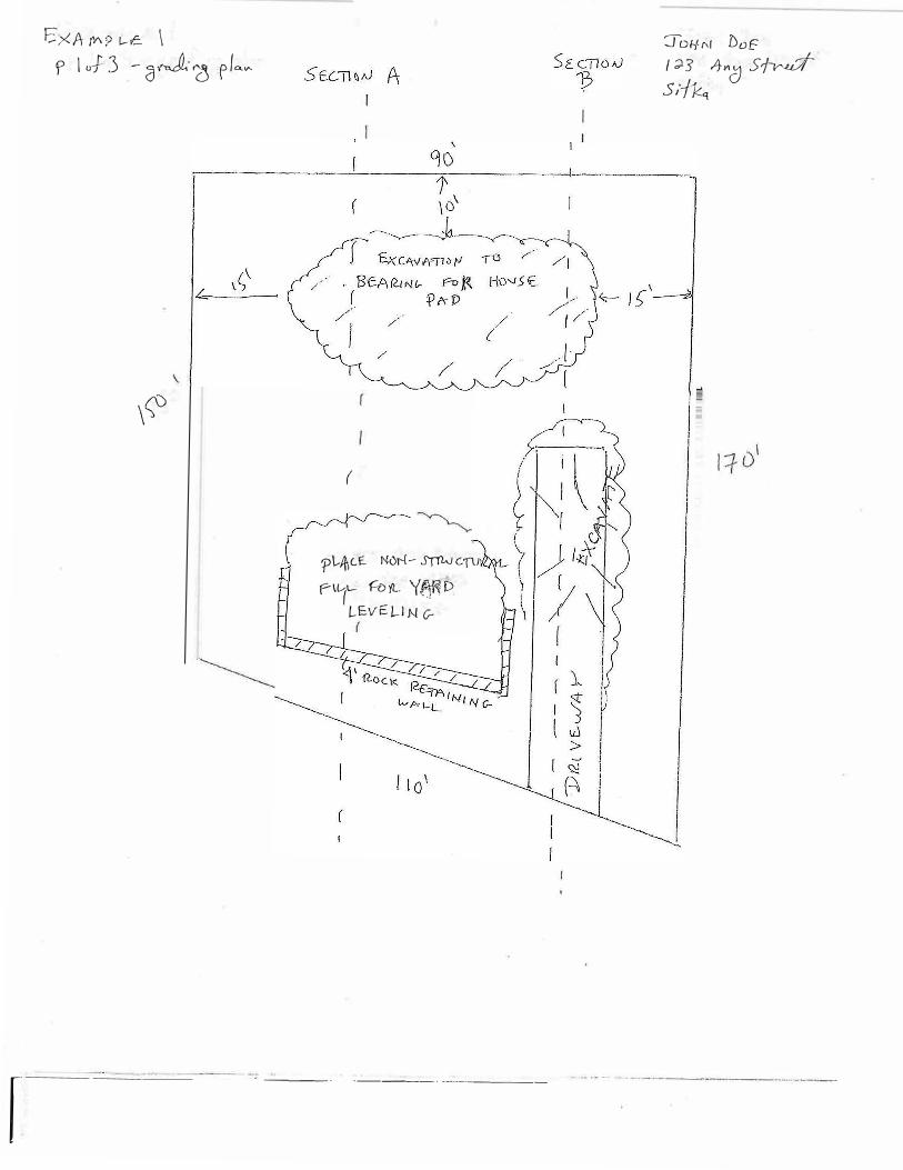
E.xA t0'? l--v� \
P l o-J 3 - c:J"J· 1ci f IQ."'
\(;)
r
(
q:>l-Jj\cJ:. Nur-(- .5'fl'W Cf\J
(-'\t-t- H)yl. Y(�D LEVE!.-.lN G-
---· -----· · ·-···-·----
JOI-fr,( DvE
I ;;i.5 ,4,.,c) Sr/� S/�
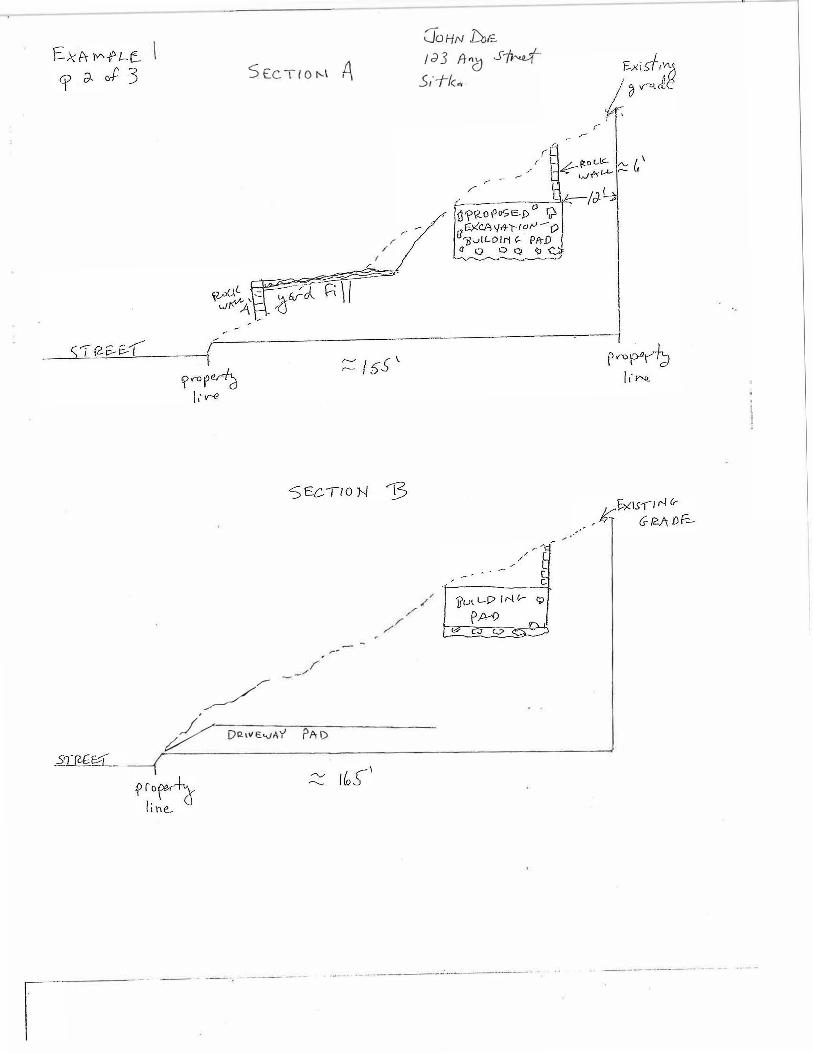
S Ee TI o t--1 A
�� /
�- D121\IE."'AY rAI)
f ,r
0oHrv DJ£
J()3 f}G Sf� .5,·--t1c.,.
'
\�
I
I ..
\
i(
/[QI
90
1
0 J
.,_1
t
.J
S::
iJ)
��
� 3
�
)__
i �
�
JOHN l)o f.
I J. 3 A "d Sfr.J S1TK4-
, ,10 '
I I I
I
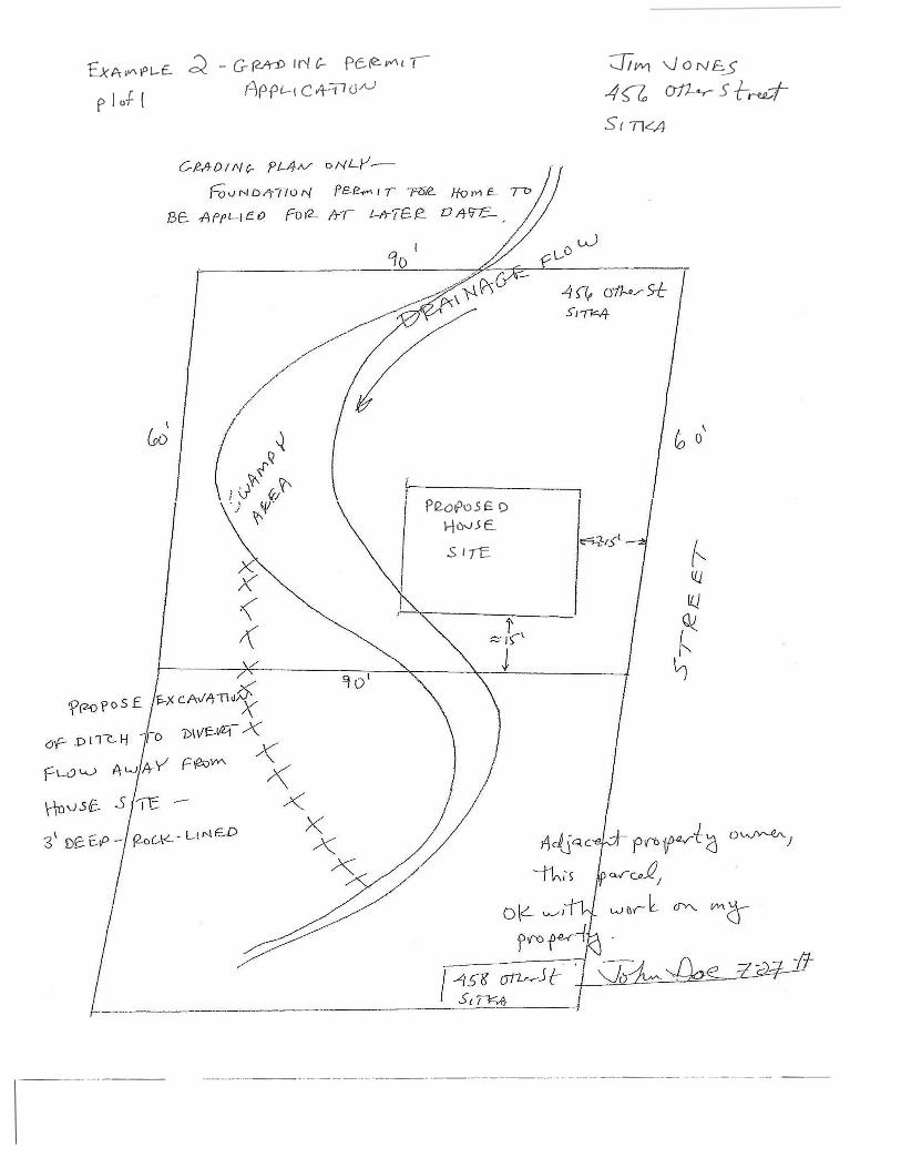
& A- if"\ I° 1-£. � - G- (?..In) ""' C- Pc.� j,Y'\ L ! °JIM '-.JONE.5
p I o-F- [
-------··-··---
f1PP£-1 C 4-TI (J N
Pf2.o�o5£ 0 i-jov.H: ..
.s I ,E.
4 a � s +-r-«..,--t
s r 71<4
·------····-----------·-·· ·---- ·--···--------···· .. ---·-·-------- ...... ·-·------ ·-·- ·--
Guidance Regarding Drainage and Erosion Control
General: Grading plans shall include a drainage plan conforming to the requirements of the adopted
grading code (1997 Uniform Building Code Appendix Chapter 33) and the Building Department's
adopted policies.
Standards: Grading plans shall comply with the requirements of municipal grading code. Post
development drainage plans shall be designed such that there will be no adverse off-site impacts. Any
net increase of water volumes shall be mitigated and/or directed to adjacent drainage systems or
receiving waters that has the demonstrated capacity to handle the new flows. The municipality may
require a dedicated drainage easement(s) to ensure proper drainage is consistent and compatible with
the surrounding drainage patterns.
Drainage Across Property Lines: Drainage across property lines shall not exceed that which existed prior
to earthwork construction. Excess or concentrated drainage shall be contained on site or directed to an
approved drainage facility. Erosion of the ground in the area of discharge shall be prevented by
installation of non-erosive down drains or other devices.
Erosion Control: The faces of excavation and fill slopes shall be prepared and maintained to control
against erosion. The protection shall be installed as soon as practicabl� and prior to scheduling final
inspections. Where necessary, check dams, cribbing, riprap, or other suitable devices or methods shall
be employed to control erosion and provide slope stability and safety.
Exception: Where cut slopes are not subject to erosion due to the erosion-resistant characteristics of
the facing materials, such protection may be omitted.