Embed Size (px)
Citation preview

College of Engineering
Electrical Engineering Department
Communication and Electronics Engineering
Bachelor Thesis
Graduation Project
Smart Security System Based on Wireless Sensor Network and
Third Generation Technology
Project Team
Duaa Tamimi Sabrin Balassi
Samah Zamareh Nidal Zaareer
Project Supervisor
Eng. Ayman Wazwaz
Hebron – Palestine
Jun. 2014
كلمة شكر
.على إتمام هذا المشروع ناالقدير على إعانته وتوفيقه ل أولا الحمد لله العلي في الهندسةتقدم بجزيل الشكر وخالص العرفان إلى الهيئة التدريسية في كلية ون
وزوز أيمن الأستاذخص بالشكر ن، و البوليتكنكجامعة
هذا، ومساهمته في رفع مستوانا بتوجيهاته الحكيمة . ناعلى إرشاده لنا في مشروعتقدم بجزيل الشكر إلى كل من ساهم بإنجاح هذا المشروع بإمداده العون نكما
..والمساعدة بشكل مباشر أو غير مباشر

إهداء
.صلى الله عليه وسلمإلى أول المعلمين سيدنا محمد كل اللحظات فكانوا نعم الأخوة ناأجمل الذكريات وكانوا مع اإلى من شاركون
والأصدقاء. إلى أسطورة الزمان شعب كنعان صانع حضارتنا.
إلى الشامخات الماجدات...... أمهات الشهداء. إلى الطيور المرفرفة....... أطفالنا المشردون تحت الحصار و القمع.
النضال. إلى أنين الجرحى و عذاب المعتقلين في دروب إلى شوارع المدينة العتيقة..... زهرة المدائن..... إلى القدس.
فلسطين من زرقة البحر إلى خضرة النهر. ناإلى وطن إلى معاناة أهلنا وذوينا من أجل أن نرى النور.
إلى أنفسنا إذا كنا نستحق ذلك.

Abstract
This project is developed and implemented as an integrated wireless
sensor system; it is specialized in safety and security issues in buildings, in
order to protect it from risks before they happen, or at least to minimize the
impact of risks as much as possible.
The first phase of the project is the Wireless Sensor Network WSN; it
contains fire and motion sensors, water pumps and doors connected to the
network using Zig-Bee technology. The second phase is the central server,
which let the users control and monitor buildings by Wi-Fi technology.
Moreover, control an IP camera using the same technology .the final phase
is the tele-controlling subsystem, which allows users to monitor and control
the whole system using 3G network. At the end, we developed a robust,
efficient and valuable system that helps to protect our stuff wherever we are.

الملخص
من شبكة باستخدام والسرقات، قرائالح من للمباني ذكي حماية نظام عن عبارة هو المشروع .اللاسلكية للهواتف الثالث الجيل وشبكات قرائوالح الإنسان حركة حساسات
خلال ومن الإنسان، من صادرة حركة او المبنى في حريق هناك كان إذا بكشف الحساسات تقوم حركة، أو حريق بوجود إشارة له ترسل (Zig-Bee) لاسلكية تقنية باستخدام دقيق مبمتحك ربطها في النجاة أبواب واغلاق بفتح أيضا ويقوم الحريق لإطفاء مياه مضخة بتشغيل المتحكم قومي وبدوره إغلاق أو للأذى، التعرض وبدون بسهولة منه الخروج من المبنى في القاطنين ليتمكن المبنى .بالداخل سارق هناك كان إن الأبواب
على بالاعتماد الكاميرا هذه وستعمل ، Wi-Fi ال تقنية على تعمل قبهرا مراكامي إلى بالإضافة لاسلكية إشارة تصل المبنى، في إنسان هناك كان حال ففي للإنسان، الحركة حساسات من إشارة الحاسوب لجهاز وارساله الفيديو تسجيلب لكاميراا تبدأ حيث Wi-Fi ل ا تقنية خلال من الكاميرا إلى خلال من الذكي الهاتف إلى الفيديو بإرسال الحاسوب جهاز يقوم وبدوره .نفسها التقنية خلال من
.اللاسلكية للهواتف الثالث الجيل شبكات
.فلسطين بوليتكنيك جامعة ،(B)مبنى في الطوابق أحد على تطبيقه تم المشروع

III
Contents
Abstract (English)…………...……………………………………………..……………….…..…I
Abstract (Arabic)…………...……………………………………………..………………...……II
Contents…….....……..………………………..……………….………………………...…...…III
List of Figures…...…………………………….……………………..……………......………VIII
List of Tables…………………………………………………..……..…………………….……X
List of Abbreviations……….…………………………………………………………….....…..XI
Chapter 1: Introduction
1.1: Overview………………………………………………………………….…….……….....…2
1.2: Project Objective……………………………………………..………………..……………..2
1.3: Motivation………………………………………….………………………………...…….…2
1.4: Requirements...……………..……………………………………………...….......………….2
1.5: Challenges…………………………………………………………………….………..…..…3
1.6: Assumptions…………………………………………………….…………………………....3
1.7: Approach………………………………………………………….………………………......4
1.8: Scenarios………………………….……………………………………...….………..........…5
1.9: Literature Review (Related Works).…………………………………………………..…...…6
1.10: Project Schedule ………………………….…………………………….……………...…...9
1.11: Budget …………………………………….………………………………...…….......…...10

IV
Chapter Two: Theoretical Background
2.1: Wi-Fi Technology
2.1.1: Introduction……………………………………………………………...….….….….12
2.1.2: Wireless Standard…………………………………….…………………………….…12
2.1.3: Advantages and limitations...……………..……………….…....…………………….13
2.1.4: Wi-Fi Camera…………………………………………………………………………14
2.2: Zig-Bee
2.2.1: Overview …………………………………………………...………………..…..….....14
2.2.2: Zig-Bee Types……..…………………………………………………………...….…...14
2.2.3: Topologies…………………………….……………………………………..............…15
2.2.4: Zig-Bee Properties…………….…………………………………………...…….….…16
2.3: 3G Technology
2.3.1: Overview ………………………………………………………………………….…...17
2.3.2: Principle …………………………………...….………………….…………………....17
2.3.3: Main Characteristic …………………………….…………………...……….…..……18
2.3.4: Advantages and Disadvantages ……………..………….……………………......……18
2.3.5: 3G Modem …………………………...………………………………………….….…18
2.4: Microcontroller
2.4.1: Introduction .……………………………………………..………………………...…..19
2.4.2: Types of Microcontroller … ……………….………….......................................……..19
2.4.3: Arduino ……………………………………….…………………………………….....20
2.4.4: Arduino Feature ...………….…………………...………………………….…..…...…20
2.5: Fire System
2.5.1: Smoke Detector ……………….……………………..……...........................................21
2.5.2: Basic Types …………………………….…...………........................................….…..21

V
2.5.3: Water Pump……………………..……………………….………..………….……...…22
2.5.4: Applications ….…………………...…………………..................................................22
2.6: Motion Sensor
2.6.1: Introduction …………………………………..…………...…………………………...22
2.6.2: Kind of Motion Detectors……………….……………………..……………………....22
2.7: Android
2.7.1: Mobile ………………………………………………………...…………………..…...24
2.7.2: Introduction …………...…………………….…………..…….……………….…........25
2.7.3: Android Architecture …………………………….……...………………………....…26
Chapter Three: Conceptual Design
3.1: System Function and Block Diagram
3.1.1: General Block Diagram…………...………………………...........................................28
3.1.2: Detailed Block Diagram………………………….…….…............................................29
3.1.3: System environment ……………..……….…...……….....................................…..…..29
3.2: Block Diagrams, Flowcharts, Illustrations for each Subsystem
3.2.1: Zig-Bee Network ……………………………….….…………………………….….…30
3.2.2:Zig-Bee Block Diagram…. …………....……...………………………..………........…31
3.2.3: Zig-Bee Network flow charts………………… ….………………...……................…31
3.2.4: Arduino………….……………………...…………………………………….…......…34
3.2.5: Arduino Interface……..…….……...………………………………………..….…...…34
3.2.6: Arduino Flow chart…………..…….…………………………………………….....….35
3.2.7: 3G and Wi-Fi Subsystem…………….…………… …………………….…….…....…36
3.2.8: Human Detection System………….……… …………………………………….....…36

VI
3.2.9: PC to (3G) Modem……..…..……..…….……………………….…………………..…37
3.2.10: Mobile Application Controlling System………… …………………….……..…...…38
3.3: System Components
3.3.1: Human Motion Detector..….………………………..……….....................................…40
3.3.2: Smoke Detector….………………...……...................................................................…41
3.3. 3: X-Bee Unit (Zig-Bee) …………..………………………………………………….…41
3.3.4: Arduino Microcontroller ……..…….…………………………………………..…...…42
3.3.5 :USB 3G Modem.……………………………………………………………..…….......43
3.3.6:Wi-Fi Camera………….………….………………………………………....….........…45
3.4: Microcontroller interfaces with Xbee unit, pump
3.4.1: Microcontroller Interface with Xbee Unit……………….…………… ……....………46
3.5: System Data Flow
3.5: System Data Flow………………………………………..…………… ……..………….47
Chapter Four: Detailed System Design
4.1: Overview………………………………………………………………………………....50
4.2: Arduino Interfacing with Zig-Bee………………………...…………………………..…50
4.2.1: Circuits Design ………………………………………………………………...…....…50
4.2.2: Xbee Interface……………….…………………...……..… ………………….........…51
4.3: Interfacing Zig-Bee with PC…………………………………………………………..…52
4.4 WSN nodes circuit design………………………………………………………….…….53

VII
Chapter Five: Software Design & Implementation
5.1: Overview……………………………………………………………………….………...55
5.2: Arduino software Programming…………………...…………………………………….55
5.3: Android Mobile Application………..……………………………………………………58
5.4: C# Programming………………………………………...……………………………….61
5.5: Zig-Bee Network Implementation………………………..……………………………...64
Chapter Six: Testing and Results
6.1: Overview…………………...………………………….…………………………………67
6.2: WSN Nodes…………...…………...…………………………………………………….67
6.3: Door Prototype…………………..……………………………………………………….70
6.4: Controlling with c#............................................................................................................71
Chapter Seven: Testing and Results
7.1: Overview…………………………………………………………………………………74
7.2: Achievements ……………………………………………………………………………74
7.3: Conclusion ………………………………...…………………………………………….74
7.4: Future work………………………………………………………………………………75
Reference………...……………………………………………………………………..….…76
Appendix A…………………………………………………………………………………...77
Appendix B…………………………………………………………….…………………..…80
Appendix C……………………………………………………………………….…………..83
Appendix D…………………………………………………………………………….……..88

VIII
List of Figures
Page Figure
4 Figure 1.1: General System Block Diagram
12 Figure 2.1: Wi-Fi technology
15 Figure 2.2: Zigbee topologies
15 Figure 2.3: Zigbee Mesh topology
21 Figure 2.4: Photoelectric smoke detector
23 Figure 2.5: Active motion detector
23 Figure 2.6: Explanation of basic sensor operation
25 Figure 2.7: Android Phone
26 Figure 2.8: Android Architecture
28 Figure 3.1:General Block Diagram
29 Figure 3.2:Detailed Block Diagram
30 Figure 3.3:System environment
31 Figure 3.4 Zig-Bee block diagram
32 Figure 3.5: Network establishing flow chart
33 Figure 3.6: Starting the Zig-Bee network flow chart
34 Figure 3.7: Arduino Interface
35 Figure 3.8: Arduino decision flow chart
36 Figure 3.9: Viewing an IP Camera video using Smartphone
37 Figure 3.10: Human detection system flow chart
38 Figure 3.11: PC to 3G modem flow chart
39 Figure 3.12: Mobile application controlling flowchart
40 Figure 3.13: Human motion detector
41 Figure 3.14: Smoke sensor
44 Figure 3.15: ZTE 3G Modem dongle
45 Figure 3.16: VisionNet security IP camera
47 Figure 3.17: Zig-Bee interference with the microcontroller
47 Figure 3.18: System data flow
50 Figure 4.1:General circuit design.
51 Figure 4.2:Xbee to Arduino interface
52 Figure 4.3: Zig-Bee interfacing with PC
53 Figure 4.4: WSN node circuit design
55 Figure 51: Definitions and pin connections
56 Figure 5.2: Pump function
57 Figure 5.3: The door function

IX
58 Figure5.4: The system compiling
59 Figure 5.5: Initial interface
59 Figure5.6: Options interface
60 Figure5.7: Live Video Streaming
60 Figure 5.8: Inserting Settings on the Android Application
61 Figure 5.9: C# program graphical user interface
62 Figure 5.10: Open connection with 3G Modem
62 Figure 5.11: Security Doors Controlling Code
63 Figure 5.12: Water Pumps Controlling Code
64 Figure 5.13: Specific settings for each Xbee unit
65 Figure 5.14: Xbee unit with MAC address
65 Figure 5.15: Message between Zig-Bee Units
67 Figure 6.1: WSN node A
68 Figure 6.2: WSN node B
68 Figure 6.3: All WSN nodes
69 Figure 6.4: Motion sensor
69 Figure 6.5: Water Pump connected to WSN node
70 Figure 6.6: Smoke sensor
70 Figure 6.7: Door Prototype
71 Figure 6.8: Door connect to node A
72 Figure 6.9: Server Connection with WSN
72 Figure 6.10: Controlling using Server

X
List of Tables
Page Table
9 Table 1.1: Project timing schedule
9 Table 1.2: Summery of project plan for the first semester
10 Table 1.3: Summery of project plan for the second semester
10 Table 1.4: Budget
13 Table 2.1: Brief overview of the four most popular current 802.11 standards
16 Table 2.2: The ZigBee properties
16 Table 2.3: ZigBee in comparison with Wi-Fi and Bluetooth
40 Table 3.1: Technical specification for human motion detector
41 Table 3.2: Physical specification for Zig -Bee unit
43 Table 3.3: Specification for Arduino
44 Table 3.4: Technical specification for 3G Modem
45 Table 3.5: Technical specification for Wi-Fi Camera
51 Table 4.1:Pins connection for Figure 4.2
52 Table 4.2: Pins connection for Figure 4.3

XI
List of Abbreviations
Abbreviation Stands for
PC Personal Computer
Wi-Fi Wireless Fidelity
PIC Programmable Integrated Circuit
3G Third Generation
HSDPA High-Speed Downlink Packet Access
GSM Global System for Mobile Communication
WSN Wireless Sensor Network
SMS Short Message Service
A/D Analog to Digital
LED Light Emitting Diode
RF Radio Frequency
IDE integrated development environment
PAN ID Personal Area Network identifier
1
Chapter 1: Introduction
1.1 Overview.
1.2 Project Objectives.
1.3 Motivation.
1.4 Requirements.
1.5 Challenges.
1.6 Assumptions.
1.7 Approach.
1.8 Scenario.
1.9 Literature Review (Related Works).
1.10 Project Schedule.
1.11 Budget.

2
1.1: Overview
In this chapter, a brief description of the system will be shown .Starting with objectives,
the goals that we are targeting to achieve will be shown by the end of this project. Then, the
hardware and software requirements and challenges, that will we face. At the end, we will show
the approach and scenario of the project.
1.2: Project Objectives
The main aim of our project is to provide the building's guard a valuable information and
ability to control, in the case theft or fire. Thereby protect the residents of the building from the
risk before it happens, or at least minimize the impact of the risk as much as possible.
We can divide objectives to the following:
Design and Implement a robust and accurate security system that can detect motion by certain
detection sensors and camera.
Automatic fire alarm system to prevent fire from burn, damage the building, by detecting fire
through smoke detectors, and automatically turn on a firefighter device (water pump).
The whole system is battery power dependent, so it is independent on buildings electricity,
which is an important matter in security issues.
System with the lowest possible costs compared to other available systems in the market.
1.3: Motivation
The building's guard is responsible in monitoring the front and back yards and building's
entries. Moreover, he is responsible in monitoring several floors and be ready for any emergency
case .The idea behind the intelligent safe building comes from the huge need of an integrated safety
system that helps the building's guard in his work, and the use of available technologies to make
this job much easier and better.

3
1.4: Requirements
This system requires hardware and software requirements in order to achieve our goals in
this project. We need sensors and security camera for detection, controllers, PC, smart phone for
monitoring and controlling, and pumps and relays to carry out orders:
Hardware requirements:
Motion, smoke sensors.
Wi-Fi camera.
X-Bee PRO S2 and X-Bee Regulator.
3G HSDPA Modem.
Arduino microcontroller.
Personal Computer (PC).
Smart phone with android platform.
Electronic firefighter (Pump).
Electronic and Electrical components.
Software Requirements:
Programming Languages such as Android, Arduino Programming Language (C), Zig-Bee
configuration, and 3Gmodem configuration.
1.5: Challenges
Some challenges we expect to face in our project:
1) Designing an accurate, efficient and valuable system, with limited hardware and software
resources.
2) Learning programming languages that we need in programming system devices.
3) Implementing a subsystem depends on 3G technology, which is not supported in our area.
4) Building live video streaming software with acceptable resolution and short delay.

4
1.6: Assumption
The project will be applied in Palestine Polytechnic University in one of the floorsin
Building "B" as following:
There will be Wi-Fi camera with human detection sensor to catch the theft when pass through
it.
Three nodes will control water pump, fire and motion sensors to sense existence of fire and
motion, automatically control and notify the guard.
1.7: Approach
This system uses wireless sensor network to protect the building from fire, accidents,
remotely control, and monitor using mobile. The following is the general block diagram.
(Interfaces will discussed later)
Figure 1.1 General System Block Diagram
5
Step by step description approach:
WSN send signal about its status to the Zig-Bee, e.g. the fire detection sensor detect a fire
accident and send this information to the nearest Zig-Bee node.
The information travels from Zig-Bee nodes to another node until it reached the central
node, which is directly connected to the PC.
Wi-Fi camera detect the human motion using sensors and send the recoded videos to the
PC device.
PC device managed the received data from camera and microcontrollers, then send it to the
3G modem.
3G modem receives signal from the PC and send it to smart phone with high speed, high
data rate.
All monitoring data will reach the guard's phone, which makes him familiar with all details
of the building (fire alarm, motion detection).
Android application allows the guard to control and overcome the accident immediately,
so he send control signal to 3G modem – PC – microcontroller.
1.8: Scenario
Location: Building B in Palestine Polytechnic University (PPU)
Security Systems
A) Indoor System:
1) At night, the motion across the university corridors or classes will be absolutely from
an unauthorized person. The human motion sensor triggers the security system by
sending its alert signal to the Zig-Bee unit, which will communicate to the Zig-Bee
coordinator .In its turn the Zig-Bee coordinator will send the signal to the PC.
2) The PC provides the gaud through the 3G modem about the sensor place.
3) The expected control step from the guard is to close the doors. The building guard can
send the order through his android application to the 3G modem then to the PC, which
will translate this signal to the microcontroller to close the doors.
6
B) Outdoor System:
1) In the case of any unexpected motion around the building within its surroundings, the
Wi-Fi human detection camera will start record the motion. Then, through the Wi-Fi
network, it will send the video to the receiver node, which is the PC in this case.
2) The PC will send the recorded video to the guard smart phone. Then, he will decide to
close the doors as the process above or to call the police.
Safety System:
At the emergency case of fire, the fire sensors will trigger the system by sending its alert
signal to the microcontroller through the Zig-Bee coordinator. The microcontroller will open the
water pump automatically, and then sends a notification to the guard. He will decide to open the
emergency doors through his android application.
1.9: Literature Review (Related Works)
Smart Farm [1]
In the project, Alsharawi et al, described the design of "chicken Eggs Farm", that allows
the system to collect the eggs automatically when its ready to be collected, without the need to get
inside the farm, and allow the manager to get an measurement for the temperature and humidity
status on the mobile, the sensors covers the farm connected via Wi-Fi network. The
Microcontroller that use in this project is PIC 16f688, it processes the temperature and humidity
in the farm, and this processed information send to the owner using GSM modem as a short
message (SMS) at his request through Wi-Fi network.
We use in our project Zig-Bee network to connected the sensors the Zig-Bee is better than
Wi-Fi because Zig-Bee is a low-cost, low power transceiver. The low cost allows the technology
to be widely deployed in wireless control and monitoring applications. Other differences, in our
project the mobile station is communicate with the system through the 3G modem, the 3G modem
is consider too much faster and higher data rate than use GSM modem.

7
A Remote Home Security System Based on WSN and GSM Technology. [2]
In this paper, Huang et al, describe the remote home security alarm with low-power
consumption system developed by applying WSN and GSM technology presented. It can detect
the theft, leaking of raw gas and fire, and send alarm message remotely. The hardware of this
system includes the single chip C5081F310, wireless receiving and sending chip CC1100 as well
as the SIMENS TC35 GSM module. The system software developed in C51 language has the
ability of collecting, wireless receiving and sending data, and can send a piece of alarm short
message to the user.
We will design a remote security system mainly for large buildings like Universities, that
needs a security guard, but it can be implemented for homes. Our system designed by using Zig-
Bee based WSN configuration for motion and fire detection, 3G technology for sending alarm
messages - including data packets - faster using 3G modem instead of GSM modem they used,
and Wi-Fi technology for remote control security cameras. We used human recognition algorithm
for detection any person who want to steal the building or damage it. Moreover, there will be an
Android platform used for controlling the whole system. This research paper is clearly part of our
widened, compact project.
Home Automation System [3]
In this project, S. Khan et al, mainly focused on the design and implementation of system
that control various appliances at home. The system used A/D converter that connected to a
temperature sensor .Moreover, a light monitoring and controlling subsystem implemented in this
project. The 89C51 microcontroller is the brain of the whole system. A java software application,
which downloaded on a fixed PC machine, presents the user interference part.
The Zig-Bee and Wi-Fi technologies with their huge benefits and challenges will be the
main advanced step in our system. Furthermore, the remotely monitoring and controlling system
will be a great change in the world of smart buildings.

8
Building Management System [4]
In this project, H. Abu Ajamia et al, design stand-alone system that utilize power
consumption and other house application (lighting management, security by using electronic lock
motion detector, water and electricity monitoring, control via voice recognition mechanism ).The
project use data base, C# programming language, sensors, GSM cellular module and PIC
microcontroller (18F4550).
Our project will focus on safety and security system in building(fire and human motion
detection) using wireless sensor network, cameras,3G modem, microcontroller, based on( Zig-
Bee, Wi-Fi) technology. Android software configuration will be used to monitoring and control
our system, which makes our project different from others .Moreover, our project not depends only
on alarm notifications, but allows the guard to give orders to overcome accidents directly.
Alarm System Using Body Detector [5]
In this project, U. Noor Din, designed alarm system adopts advanced RF oscillators
matched with reliable software technology and advanced hardware circuitry. It integrates
capacitance detection, network search, and automatic voice alarm. This system mainly uses
capacitance detector, body-intruding detection to transmit alarming signal to main unit. When
signal received, it processes it immediately, and then main unit will automatically give an alarm
by the designed code. In this project, a Microcontroller PIC16F877 will be used as an actuator of
the system that will control the output system through a programming system. The system will be
developed to control the system flow such as register data, delete data, and creating program flow
to produce the output depends on the activation of body detector hardware circuitry. The
PIC16F877 microcontroller will analyze and process the data and if the data has been registered
in the system, the security application will work such as triggering the buzzer and LED.
In our project, we will use cameras for human detection instead of using capacity sensors,
for tow advantages, traditional security monitoring and human detection. Although using capacity
sensors is useful technique it probably less accurate than others.
9
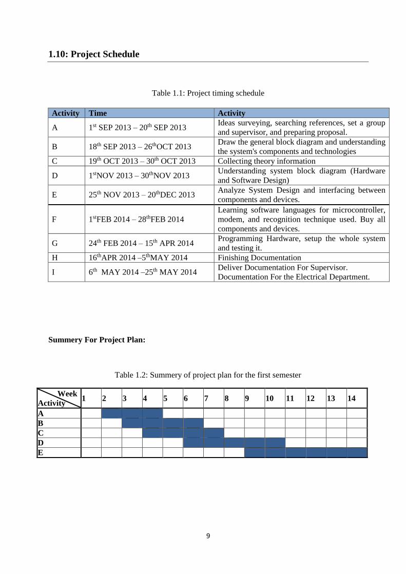
1.10: Project Schedule
Table 1.1: Project timing schedule
Summery For Project Plan:
Table 1.2: Summery of project plan for the first semester
Week
Activity 1 2 3 4 5 6 7 8 9 10 11 12 13 14
A
B
C
D
E
Activity Time Activity
Ideas surveying, searching references, set a group
and supervisor, and preparing proposal. 1st SEP 2013 – 20th SEP 2013 A
Draw the general block diagram and understanding
the system's components and technologies 18th SEP 2013 – 26thOCT 2013 B
Collecting theory information 19th OCT 2013 – 30th OCT 2013 C
Understanding system block diagram (Hardware
and Software Design) 1stNOV 2013 – 30thNOV 2013 D
Analyze System Design and interfacing between
components and devices. 25th NOV 2013 – 20thDEC 2013 E
Learning software languages for microcontroller,
modem, and recognition technique used. Buy all
components and devices.
1stFEB 2014 – 28thFEB 2014 F
Programming Hardware, setup the whole system
and testing it. 24th FEB 2014 – 15th APR 2014 G
Finishing Documentation 16thAPR 2014 –5thMAY 2014 H
Deliver Documentation For Supervisor.
Documentation For the Electrical Department. 6th MAY 2014 –25th MAY 2014 I

11
Table 1.3: Summery of project plan for the second semester
Week
Activity 1 2 3 4 5 6 7 8 9 10 11 12 13 14
F
G
H
I
1.11: Budget
Table 1.4: Budget
Equipment Quantity Price / Unit
Arduino Microcontroller 2 163 $
3G modem 1 200 $
Security Camera (Wi-Fi camera) 1 400 $
X-bee transceiver 3 20 $
Automatic Water Pump 1 131 $
Fire Sensors 2 60 $
Motion Sensors 2 46 $
Documentations - 50 $
Others - 140 $
Total 13 1210 $

11
Chapter 2: Theoretical Background
2.1 Wi-Fi Technology.
2.2 Zig-Bee Theory.
2.3 3G Technology.
2.4 Microcontroller.
2.5 Fire System.
2.6 Motion sensor.
2.7 Android.

12
2.1: Wi-Fi Technology
2.1.1 : Introduction
Short for "wireless fidelity", Wi-Fi is one of the most popular wireless communication
standards on the market. Wi-Fi is technically a trademarked brand name for the wireless standard
owned by the Wi-Fi Alliance, much like Bluetooth is trademarked by the Bluetooth Special Interest
Group. In its fledgling stages, Wi-Fi technology was almost solely used to wirelessly connect
laptop computers to the Internet via local area networks (LANs), but thanks to the immense
flexibility the technology provides, that's no longer the case. Wi-Fi technology now found in a host
of non-computer electronic devices as well, such as home theater receivers, video game consoles,
Blu-ray player digital cameras, and even GPS devices.
Figure 1.1: Wi-Fi technology
2.1.2: Wireless Standards
The official name for the specification is IEEE 802.11, and it is comprised of more than 20
different standards, each of which denoted by a letter appended to the end of the name. The most
familiar standards are 802.11b and 802.11g (Wireless B and G) which are used in the majority of
commercial Wi-Fi devices. Both of these standards operate in the 2.4 GHz band, and the only
major difference between the two is the transfer rate (see chart below).
Some consumer electronics, however, use a different standard — Wireless A. These
devices operate within the 5 GHz range and have transfer rates equivalent to 802.11g. However,
since they operate on different frequencies, devices using the 802.11a standard can't communicate
with B and G-enabled devices.

13
The newest standard, dubbed 802.11n was designed to replace all three of the previous
standards. It's up to five times faster than 802.11g, with a range almost twice as far. It also adds
multiple-input multiple-output (MIMO) technology, which uses multiple antennas to increase data
transfer rates. The 802.11n standard was drafted to allow up to four channel configurations with
potential speeds up to 600 Mb/sec. It is becoming increasingly popular for its high speeds, which
allow for smoother audio and video streaming among devices.
The table below provides a brief overview of the four most popular current 802.11 standards.
Table 2.1: Brief overview of the four most popular current 802.11 standards
Standard Frequency Data Transfer Rate Typical (Max) Range (indoor)
802.11a 3.7/5 GHz 20 (54) Mb/sec About 35 m (115 ft.)
802.11b 2.4 GHz 5.5 (11) Mb/sec 38 m (125 ft.)
802.11g 2.4 GHz 22 (54) Mb/sec 38 m (125 ft.)
802.11n 2.4/5 GHz 110+ (300+) Mb/sec 70m (230ft)
2.1.3: Advantages and Limitations
Advantages:
The Wi-Fi technology have many advantages some of them are:
1) Unparalleled mobility and flexibility
2) Quick, easy setup
3) Fast data transfer rates
4) Flexibility to connect Wi-Fi camera with PC and Arduino.
5) Quick, easy setup, do not need complex configuration to connect devices. Fast data transfer rates,
that we need it specially to transfer lifetime video from Wi-Fi to PC camera immediately.

14
Limitations:
So far, we've covered some of the advantages offered by Wi-Fi wireless technology, but
there are some limitations that must be addressed as well. Security and interference are the main
issues with current Wi-Fi standards.
1) Security concerns
2) Interference from other devices.[6]
2.1.4: Wi-Fi Camera
A Wireless IP Camera lets you view real-time images over the Internet. In other words,
you can monitor your home or office from a distant location using a PC, even a Multi-Function
mobile telephone or PDA. Network cameras even feature a built-in Web server function, so the
network camera does not have to be connected to a PC.
Wireless means that you can set up wireless IP cameras anywhere without
cumbersome LAN cable connections. Most wireless IP cameras support the 802.11g
54-Mbps / IEEE 802.11b 11-Mbps wireless communication protocol and the latest
Wireless-N 802.11n for fast transmission of recorded images to a distant PC. [7]
2.2: Zig-Bee Theory
2.2.1: Overview
Zig-Bee is a specification based on the IEEE 802.15.4 standard for wireless personal area
networks (WPANs). Zig-Bee operates in the ISM radio bands, and it defines a general-purpose,
inexpensive, self-organizing, mesh network for industrial control, embedded sensing, medical data
collection, smoke and intruder warning, building automation and home automation.
2.2.2: Zig-Bee Types
There are three different types of Zig-Bee devices in a Zig-Bee network:
1) Coordinator (Master): Only one coordinator exists in each Zig-Bee network. Its function is to
store information about the network and to determine the optimum transmission path between
any two points of the network.
2) Full function device (Router, Repeater): Routers act as an intermediate repeater that passes
data from other devices.
3) Reduced Function Device (End Device): This device contains a minimal amount of
functionality to enable it to talk to its parent node (either the coordinator or a router); itcannot
relay data directly from other devices.

15
2.2.3: Topologies
There are three types of Zig-Bee topologies:
Mesh
Star
Cluster Tree
Figure 2.2 Zig-Bee topologies
We will implement the mesh topology, since it provides three enhanced capabilities to the
wireless network as shown in figure 2.3.Extended range through multi-hop, ad-hoc formation of
the network, and most importantly automatic route discovery and self-buildings. [8]
Figure 2.3 Zig-Bee Mesh topology

16
2.2.4: Zig-Bee properties
The following table summarizes the properties of the Zig-Bee technology:
Table 2.2: The Zig-Bee properties
Zig-Bee vs. other technologies:
Table 2.3: Zig-Bee in comparison with Wi-Fi and Bluetooth

17
Based on the previous table (Table 2.3) the Zig-Bee technology will fit our needs to build
a wireless sensor monitoring and control system, because it is:
1) Highly reliable :the Zig-Bee can achieve high reliability in a number of ways :
o IEEE 802.15.4 with O-QPSK & DSSS.
o CDMA-CA
o 16 bit CRC's
2) Able to achieve very low power: devices in Zig-Bee network can operate for years on a pair
of AA batteries.
3) Highly secured: it is an internationally recognized and trusted standard. It is free patent
infringements.
4) An open global standard: Zig-Bee uses as its foundation of IEEE 802.15.4 specification for
lower MAC and physical layers. The IEEE defines a reliable radio slandered in the 2.4GHz
bandwidth, which used worldwide.
2.3: 3G Technology
2.3.1: Overview
Short for third generation is the third generation of mobile telecommunication technology.
3Gtelecommunication networks support services that provide an information transfer rate of at
least 200 Kbit/s. However, many services advertised as 3G provide higher speed than the minimum
technical requirements for a 3G service. Later 3G releases, often denoted 3.5G and 3.75G, also
provide mobile broadband access of several Mbit/s to smart phones and mobile modems in laptop
computers.3G finds application in wireless voice telephony, mobile Internet access, fixed wireless
Internet access
2.3.2: Principle
3G works by parceling the data sent on the network into small packets. These packets are
then assembled in the correct order at the receiver’s end. This is very different from normal 2G
(GSM) technology, in which a small portion of the network is ‘reserved’ or kept open for a call.
Thanks to this parceling process, 3G networks are able to send more data efficiently in a shorter
period of time, smart 3G technology also enables mobile service providers to know the location
(to within a new meters) of the handsets using their service. This not only allows them to send
information about offers in certain areas (say, if you are near a restaurant your service provider
might send you a message about a special dish being served there on that particular day), but is
also immense help in case of emergencies those who are lost can find their way out or the police
18
can be directed to them, based on information from the service provider about the location of the
phone. [9]
2.3.3: Main Characteristics
• IP connectivity, which is packet based.
• Multimedia services with streaming audio and video.
• Email with full-fledged attachments such as Power Point files.
• Instant messaging with video / audio clips.
• Fast downloads of large files such as faxes and PowerPoint files.
• Access to corporate applications.
2.3.4: ADVANTAGES and DISADVANTAGES
ADVANTAGES
High-speed network for communication.
Customer can see video or satellite based programs like TV programs using this technology.
The many in one services will be available at the same network. Due to use of the DTH & the
3G technology, everyone will use multi-purpose services to avoid time loss and keeping
records for different service providers.
DISADVANTAGES
• High costs (the technology and the maintenance are more expensive than the ones in 2G
networks, reflecting in higher end-consumer prices)
• Base stations need to be closer to each other (again more cost). [10]
2.3.5: 3G modem
A 3G modem is a device that allows a computer to connect to the internet via a high-speed
mobile broadband connection. This means that the internet signal broadcast over the airwaves

19
rather than sent and received through a cable or telephone line. The technology is largely the same
that used for delivering internet content to modern cell phones.
There are a variety of broadcasting standards covered by the 3G title, which is short for the
"third generation" of mobile technologies. The most common standards in the United States are
UMTS and CDMA. Because the various standards are not always compatible with one another,
users must check carefully that a 3G modem is compatible with the cell phone network from which
they intend to get 3G service.
In most cases, a 3G modem will come as a plug-in device, often referred to as a dongle.
This is usually plugs into a USB slot on a computer and closely resembles a portable memory
drive. The device houses the antennae that receive the signal, the SIM card that authenticates the
user to communicate on the network, and the modem itself, which converts the wireless
information into data the computer can understand. [11]
2.4: Microcontroller
2.4.1: Introduction
A microcontroller is a self-contained system with peripherals, memory and a processor that can
be used as an embedded system. Most programmable microcontrollers that are used today are
embedded in other consumer products or machinery including phones , peripherals,automobile
and household appliances for computer systems. Due to that, another name for a microcontroller
is "embedded controller." Some embedded systems are more sophisticated, while others have
minimal requirements for memory and programming length and a low software complexity. Input
and output devices include solenoids, LCD displays, relays, switches and sensors for data like
human detection, fire system, amongst others.
2.4.2: Types of Microcontrollers
There are several different kinds of programmable microcontrollers at future electronics
many of the most common types categorized by several parameters including Bits, Flash size,
RAM size, number of input/output lines, packaging type, supply voltage and speed. Our parametric
filters will allow you to refine your search results according to the required specifications.
Programmable microcontrollers contain general-purpose input/output pins. The number of
these pins varies depending on the microcontroller. They can be configured to an input or an
output state by software. When configured to an input state, these pins can be used to read
21
external signals or sensors. When they are configured to the output state, they can drive external
devices like those that LED displays and motors.
Common type's microcontroller:
1) 1-PIC (PIC 18 family and PIC16 family)
2) 2-Arduino
3) 3-Intel (8048, 8051, and 8086). [12]
2.4.3: Arduino
Arduino is a single-board microcontroller to make using electronics in multidisciplinary
projects more accessible. The hardware consists of an open-source hardware board designed
around an 8-bit Atmel AVR microcontroller, or a 32-bit Atmel ARM. The software consists of a
standard programming language compiler and a boot loader that executes on the microcontroller.
Arduino boards can be purchased pre-assembled or as do-it-yourself kits. Hardware design
information is available for those who would like to assemble an Arduino by hand. It estimated in
mid-2011 that over 300,000 official Arduino had been commercially produced.
.
2.4.4: Arduino Feature
Some of the features of the Arduino include:
An open source design. The advantage of it being open source is that it has a large
community of people using and troubleshooting it. This makes it easy to find someone to
help you debug your projects.
An easy USB interface. The chip on the board plugs straight into your USB port and
registers on your computer as a virtual serial port
Very convenient power management and built-in voltage regulation. You can connect an
external power source of up to 12v and it will regulate it to both 5v and 3.3v. It also can be
powered directly off of a USB port without any external power.[13]

21
2.5: Fire system
2.5.1: Smoke Detector
A smoke detector is a device that senses the presence of smoke in a building and warns the
occupants, enabling them to escape a fire before succumbing to smoke inhalation or burns.
Equipping a home with at least one smoke detector cuts in half the chances that the residents will
die in a fire. In 1992, the readers of R&D Magazine selected home smoke alarms as one of the "30
Products that Changed Our Lives." Smoke detectors became widely available and affordable in
the early 1970s. Prior to that date, fatalities from fires in the home averaged 10,000 per year, but
by the early 1990s, the figure dropped to fewer than 6,000 per year.
2.5.2: Basic types of Smoke Detector
The photoelectric smoke detector: uses an optical beam to search for smoke. When smoke
particles cloud the beam, a photoelectric cell senses the decrease in light intensity and triggers
an alarm. This type of detector reacts most quickly to smoldering fires that release relatively
large amounts of smoke.
Figure 2.4 Photoelectric smoke detector
The second type of smoke detector, known as an ionization chamber smoke detector (ICSD), is
quicker at sensing flaming fires that produce little smoke. It employs a radioactive material to
ionize the air in a sensing chamber; the presence of smoke affects the flow of the ions between
a pair of electrodes, which triggers the alarm. Between 80 and 90% of the smoke detectors in
(American homes) are of this type. Although most residential models are self-contained units
that operate on a 9-volt battery. [14]

22
2.5.3: Water Pump
A pump is a device that raises or transfers fluids. Pumps selected processes to not only raise
and transfer fluids, but also to meet some other criteria. This other criteria may be constant flow rate
or constant pressure.
2.5.4: Water Pump Applications
Pumps used for variety applications. Here is a list of a few applications:
Drainage - Used to control the level of water in a protected area.
Sewage - Used in the collection and treatment of sewage.
Irrigation - Used to make dry lands agriculturally productive.
Chemical Industry - Used to transport fluids to and from various sites in the chemical plant.
Petroleum Industry - Used in every phase of petroleum production, transportation, and refining.
Medical Field - Used to pump fluids in and out of the body.
Steel Mills - Used to transport cooling water.
2.6: Motion Sensor
2.6.1: Introduction
A motion detector is a device that monitors a field of view and performs a function if
motion detected within that field. The function might be to trigger the opening of a door, as in the
case of a grocery store; start a videotape machine for surveillance; turn on floodlights; or sound an
alarm. A motion detector might detect motion with optics or acoustics and can be passive or active.
2.6.2: Kinds of motion detectors
Active motion detectors:
An active motion detector emits optics or sound waves and measures feedback to detect
motion. The simplest type of active motion detector commonly used in commercial doorways to
trigger a doorbell. A device fixed to one side of the doorway, an optical sensor to the other. A
beam of light passes from the device to the sensor. When someone enters the establishment, the
beam is broken, triggering the doorbell.

23
Another kind of active motion detector used at grocery stores to automatically open the
doors for customers. Other active motion detectors emit ultrasonic acoustic waves to detect motion.
Any object moving across that plane will disturb the acoustic signature and change the picture.
The human ear cannot detect ultrasonic waves, but certain animals are sensitive to ultrasonic
signals. Some motion detectors can be set to be less sensitive to the movement of small animals.
They transmit energy and look for a frequency (Doppler) shift due to motion in the covered
area. The microwave motion detector sends out high radio frequency waves and then detect the
level of energy reflected back to the device. If the radio frequency wave hits a moving object, the
frequency changes and the motion detector activated. [16]
Figure 2.5: Active motion detector
Passive infrared (PIR) motion detectors:
Commonly used inside homes, linked to security systems. PIR sensors allow you to sense
motion, almost used to detect whether a human has moved in or out of the sensors range. They are
small, inexpensive, low power, easy to use and do not wear out. For that reason, they commonly
found in appliances and gadgets used in homes or businesses. They are often referred to as PIR,
"Passive Infrared", "Piezoelectric", or "IR motion" sensors.
PIRs made of a pyro electric which can detect levels of infrared radiation. Everything emits
some low level radiation, and the hotter something is, the more radiation emitted. The sensor in a
motion detector actually split in two halves. For many basic projects or products that need to detect
when a person has left or entered the area, or has approached.

24
To explain how a basic sensor works, see Figure2.6
Figure 2.6: Explanation of basic sensor operation
The PIR sensor has two slots; each slot is made of a special material that is sensitive to IR. The
lens used here is not really doing much and so we see that the two slots can see out past some distance
(the sensitivity of the sensor). When the sensor is idle, both slots detect the same amount of IR, the
ambient amount radiated from the room, walls, or outdoors. When a warm body like a human or animal
passes by, it first intercepts one-half of the PIR sensor, which causes a positive differential change
between the two halves. When the warm body leaves the sensing area, the reverse happens, whereby
the sensor generates a negative differential change. These change pulses are what detected. [17]
2.7: Android
2.7.1: Mobile
Mobile phone is one of the most sophisticated and modern techniques that spread
dramatically in our societies, it transformed from a simple use to make call, to be used nowadays
in many complex and useful applications.
The most common mobile operating systems are:
Android is a Linux-based operating system (open source).
IPhone OS FROM apple Inc. (closed source).
Blackberry OS from RIM (closed source).
Windows phone from Microsoft (closed source).

25
In our system Android is the operating system that we want to use in order to support our project
objective requirements, like in Figure 2.7
Figure 2.7 Android Phone
2.7.2: Introduction
Android is one of the most versatile, powerful and elegant platforms coming out of Google
in recent. It initially developed by Android Incorporation. Later purchased by Google and
positioned in the Open Handset Alliance.
Android is an open source platform and it is released under open source license. The
Android operating system software stack consists of Java applications running on a Java based
object oriented application framework on top of Java core libraries running on a Dalvik virtual
machine featuring JIT compilation. Libraries written in C include the surface manager, Open Core
media framework, SQ Lite relational database management system, OpenGL ES 2.0 3D ,graphics
API, Web Kit. Layout engine, SGL graphics engine, SSL, and Bionic.
Applications: Android will ship with a set of core applications including an email client, SMS
program, calendar, maps, browser, contacts, and others. All applications written using the Java
programming language.

26
2.7.3: Android Architecture
The following diagram shows the major components of the Android operating system. [18]
Figure 2.8 Android Architecture

27
Chapter 3: Conceptual Design
3.1 System Function and Block Diagram.
3.2 Block diagrams, Flow Charts, and Illustrations for each
Subsystem.
3.3 System Components.
3.4 Microcontroller Interfaces with Xbee Unit, Water Pump
3.5 Data Flow.
28
3.1: System Function and Block Diagram
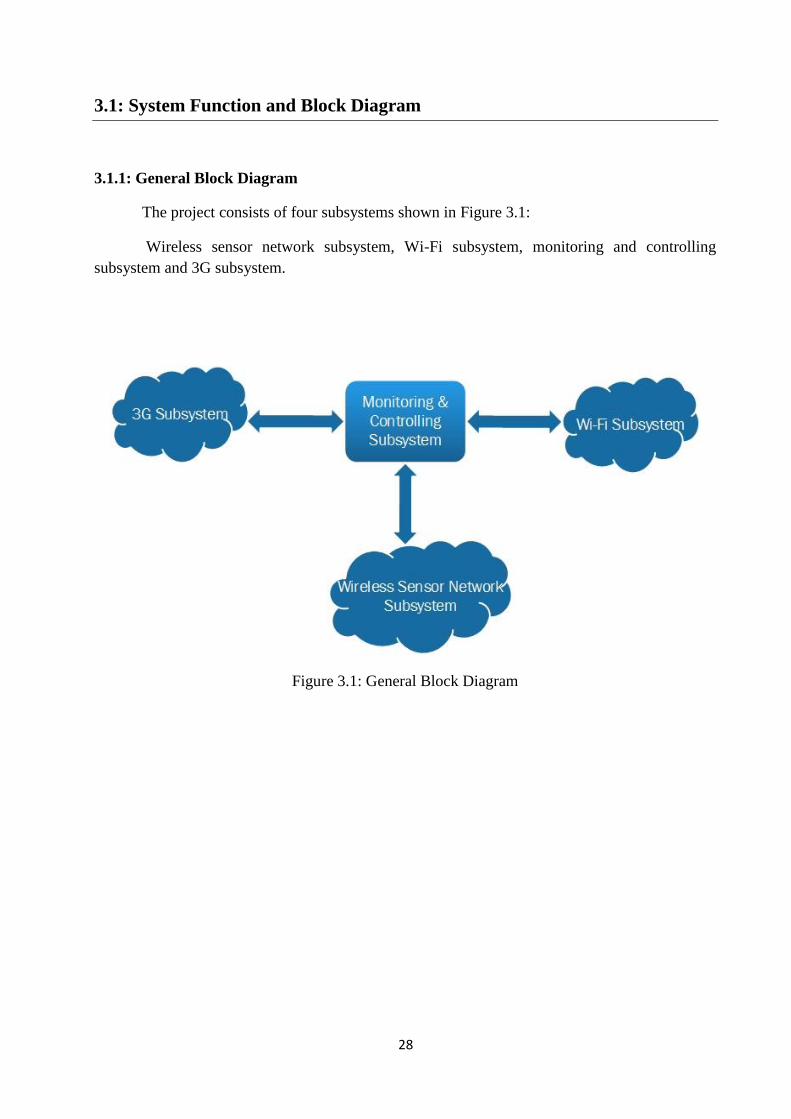
3.1.1: General Block Diagram
The project consists of four subsystems shown in Figure 3.1:
Wireless sensor network subsystem, Wi-Fi subsystem, monitoring and controlling
subsystem and 3G subsystem.
Figure 3.1: General Block Diagram

29
3.1.2: Detailed Block Diagram
All system components and interfaces shown in figure3.2. Four subsystems (wireless sensor
network subsystem, Wi-Fi subsystem, monitoring and controlling subsystem and 3G subsystem)
are connected to perform the smart security system.
Figure 3.2: Detailed Block Diagram
3.1.3: System Environment
The wireless sensor network will be submitted in the seventh floor of building B.Th.
network consists of three sections, two sections contains motion and fire sensor connected to a
microcontroller, which will transmit its data to the central Zig-Bee node. In fire alarm system, two
smoke sensors will be installed in the University. A water pump will be used to overcome the fire.

31
In monitoring system, we aim to detect human motion in four directions, a Wi-Fi camera
and two human motion sensors with sensing range up to 12 meters will be installed in our
university.
Figure 3.3: System Environment
3.2: Block Diagrams, Flow charts, Illustrations for each Subsystem
3.2.1: Zig-Bee Network
In our project, we are going to use three (X-bee Pro S1) units. One of them will be the network
coordinator and the other two will be transceivers.

31
3.2.2: Zig-Bee Block Diagram
Figure 3.4: Zig-Bee block diagram
Figure3.4 shows the main Zig-Bee components in the system .The Zig-Bee network
consists of X-bee coordinator and two X-bee routers. The X-bee coordinator connected to the PC,
each X-bee router connected to a microcontroller that is responsible to connect the network to the
sensors.
3.2.3: Zig-Bee Network Flow Charts:
Figure3.5 shows the network establishing flow chart:
It describes the delivering signals technique from PC to the Arduino microcontrollers to control
the system.

32
Figure 3.5: Network Establishing Flow Chart
The following flow chart in Figure 3.6 shows that the coordinator responsible for starting the
Zig-Bee network
Start
X-bee coordinator receives data
from Arduino Microcontroller
Routing packet in Ad-hoc Network
Deliver data to Arduino
End

33
Figure 3.6: Starting the Zig-Bee network flow chart
Network initialization involves the following steps:
1) Search for a Radio Channel The coordinator first searches for a suitable radio channel (usually the one, which has least
activity).
2) Assign PAN ID
The coordinator starts the network, assigning a PAN ID (Personal Area Network identifier)
to the network.
3) Start the Network
The coordinator then finishes configuring itself and starts itself in coordinator mode. It is
then ready to respond to queries from other devices that wish to join the network.
34
3.2.4: Arduino
In our project, we are going to use two Arduino Uno, to construct the wireless sensor network.
Arduino function: The functions of Arduino which is divided into two parts (Input, Output).
The input functions are:
Read the incoming signal from sensors (motion, fire) through Zig-Bee
Receive control signal from the mobile through PC.
The output functions are:
If there are a fire detection turn on the water pump and send control signal to close or
open the doors.
Send control signal to turn the Wi-Fi camera through the PC ,if there is a human motion
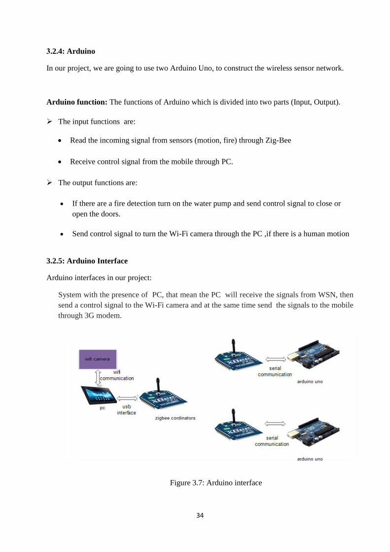
3.2.5: Arduino Interface
Arduino interfaces in our project:
System with the presence of PC, that mean the PC will receive the signals from WSN, then
send a control signal to the Wi-Fi camera and at the same time send the signals to the mobile
through 3G modem.
Figure 3.7: Arduino interface

35
3.2.6: Arduino Flow Chart
The decision points that the Arduino will take divided in two parts as Figure 3.8
Figure 3.8: Arduino decision flow chart
Arduino processes the commands received from Zig-Bee and decisions as follows:
1) If this command is about fire, WSN sends the signal to pc. This signal contains
information about the place of fire.
2) If this command is about human motion, WSN send control signal to get video from
camera.

36
3.2.7: 3G and Wi-Fi subsystem
Interface Wi-Fi camera with smart phone:
For viewing an IP Camera video using smartphone, there are five components to the system:
1) IP camera, it needs to compress the video so that it uses as little data as possible to see the
video without reducing the resolution.
2) Personal computer needed to transfer video captured from IP camera to 3G Modem connected
to USB port of the PC.
3) The Data Rate available at our cellular modem is maximum 7.2 Mbps, which is enough to
handle the data flow we need.
4) Phone company cellular system has 5 MHz bandwidth, which is very good to carry our data
flow.
5) Smartphones has excellent performance to support the latest cellular services and to display
the video.
Figure 3.9: viewing an IP Camera video using Smartphone
3.2.8: Human Detection system
Wi-Fi camera will depends on human motion sensors to detect humans, so the camera will
be in silent mode by default, and it starting capturing when it receives a control signal from
Arduino due to WSN sensing.

37
Figure 3.10: Human detection system flow chart
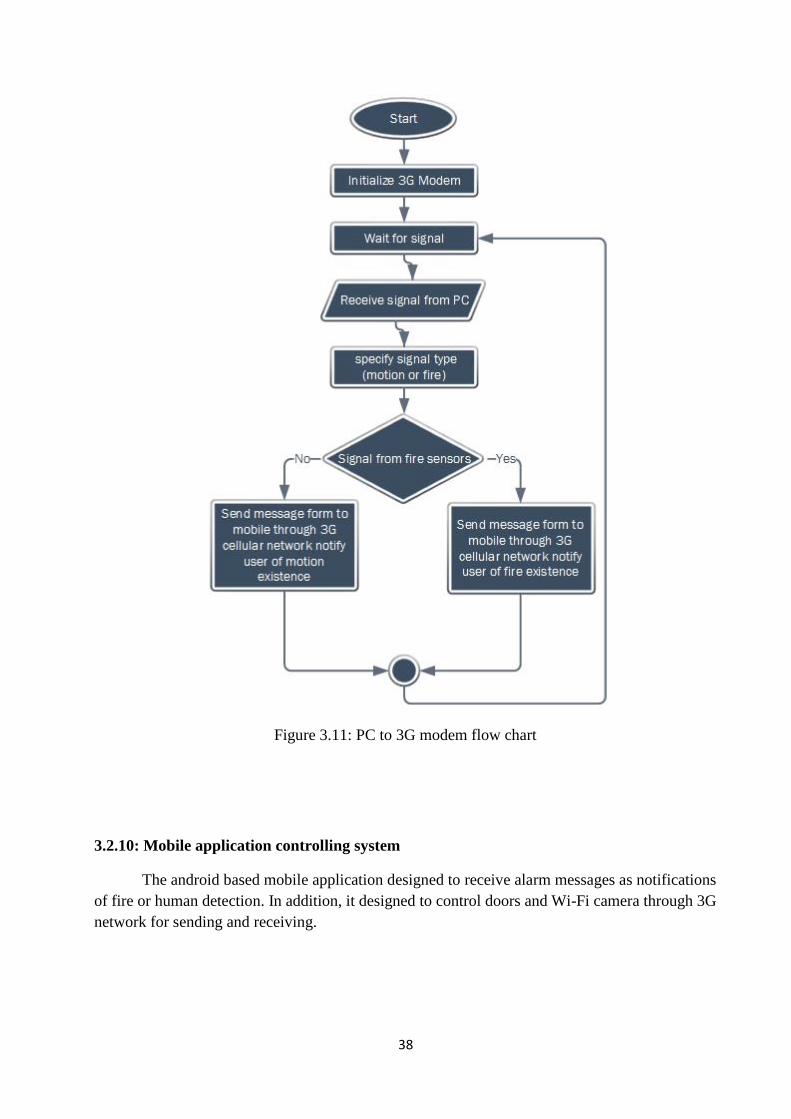
3.2.9: PC to (3G) Modem
3G modem programmed to send alarm messages and video to the smartphone, and to
receive different control signal from smartphone as follows:
38
Figure 3.11: PC to 3G modem flow chart
3.2.10: Mobile application controlling system
The android based mobile application designed to receive alarm messages as notifications
of fire or human detection. In addition, it designed to control doors and Wi-Fi camera through 3G
network for sending and receiving.

39
Figure 3.12: Mobile application controlling flow chart

41
3.3: System Components
3.3.1: Human motion detector
Figure 3.13 shows the human motion detector .We will use IS215T Honeywell Standard PIR,
which is an entry-level passive infrared motion sensor.
Figure 3.13: Human motion detector
Technical Specification:
Table 3.1: Technical specification for human motion detector
Sensor Honeywell Standard PIR
Operating Voltage 12V DC
Range 12 meters +/- 1m @ 20C, @ 2.4 m high, two steps
walk at 1m/sec
Indicators Red LED for alarm
Optical Filtering White light protection, pigmented lens
41
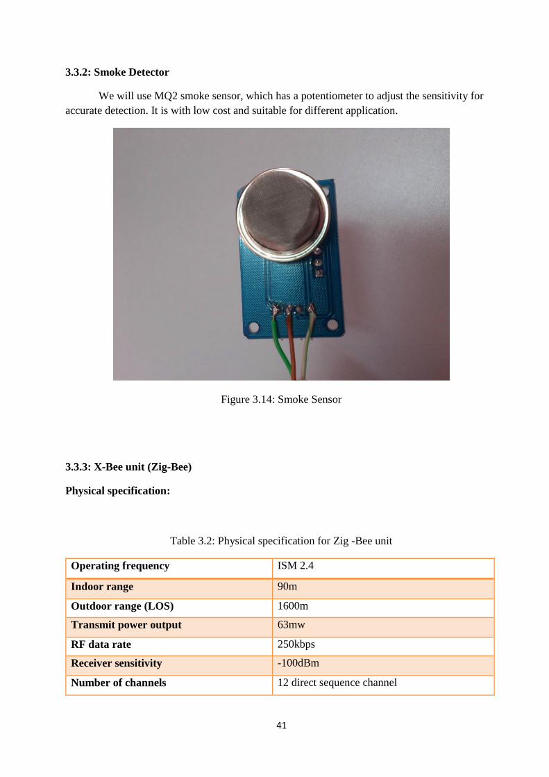
3.3.2: Smoke Detector
We will use MQ2 smoke sensor, which has a potentiometer to adjust the sensitivity for
accurate detection. It is with low cost and suitable for different application.
Figure 3.14: Smoke Sensor
3.3.3: X-Bee unit (Zig-Bee)
Physical specification:
Table 3.2: Physical specification for Zig -Bee unit
Operating frequency ISM 2.4
Indoor range 90m
Outdoor range (LOS) 1600m
Transmit power output 63mw
RF data rate 250kbps
Receiver sensitivity -100dBm
Number of channels 12 direct sequence channel

42
The above table explain some physical specifications about the (X-Bee Pro S1) component. In our
project, we are going to use three (X-Bee Pro S1) units .one of them will be the network coordinator
and the other two will be transceivers.
3.3.4: Arduino Microcontroller
The microcontroller is the brain of the automation management system that we are going
to build; we should look for the flexibility in those processors is that they will give to the system.
We have a limited time to develop the project, so we need the easiest and cheapest solution in
order to satisfy the goals of the system, looking to that we will try to find a hardware that can be
highly compatible with Zig-Bee and Wi-Fi communication. They should have low power
consumption, and have enough I/O input to control of the system.
One of the most important features that we would like to add to the system is that it should
be completely Open Hardware/Software, so we need a microcontroller, can be programmed using
Open Source Software.
Filtering these criteria, we will compare Arduino Uno and Arduino Mega:
Arduino Uno
It is the standard Arduino, it uses 8-bit microcontroller, ATmega328, and it has 32 Kb flash
memory, 2 Kb RAM, 16 MHz, 1 Serial port analog I/O ports, 13 digital ports.
Arduino Mega
It is the big one of the Arduino family, it based on ATmega1280. It has 54 digital input/output
pins (of which 14 can be used as PWM outputs), 16 analog inputs, 4 UARTs (hardware serial
ports), a 16 MHz crystal oscillator.
Arduino Uno vs. Arduino Mega:
These are some of the reasons of why we chose Arduino Uno to develop the system:
It is easily available than Arduino Mega
It is low cost; in our project, we will design system lower cost than other system will
present in the market.
Arduino Uno:
The Arduino Uno is a microcontroller board based on the ATmega328 (datasheet). It
has 14 digital input/output pins (of which 6 can be used as PWM outputs), 6 analog inputs, a
16 MHz ceramic resonator, a USB connection, a power jack, an ICSP header, and a reset

43
button. It contains everything needed to support the microcontroller, simply connect it to a
computer with a USB cable or power it with AC-to-DC adapter or battery to get started.
Specification for Arduino:
Table 3.3: Specification for Arduino
Microcontroller ATmega328
Operating Voltage 5V
Digital I/O Pins 14 (of which 6 provide PWM output)
Analog Input Pins 6
Flash Memory 32 KB (ATmega328) of which 0.5 KB used by boot loader
SRAM 2 KB
EEPROM 1 KB
Clock Speed 16 MHz
3.3.5: USB 3G Modem
A USB 3G modem (dongle) allows a computer to connect to the Internet via a high-speed
mobile broadband connection. This means that the Internet signal broadcasted over the airwaves
rather than sent and received through a cable or telephone line. The included SIM
card authenticates the user to communicate on the network, and the modem itself, which converts
the wireless information into data the computer can understand.
We need this device in our project to send alarm messages that includes data to the mobile
application, sends video streaming captured from Wi-Fi camera, and receive control messages
(signals) to control other system components. This 3G modem is better than GPRS one, cause it
can transmit and receive data in a high speed and low delay. Controlling (programming) the 3G
modem achieved by using AT commands. 3G Modem programming will be discussed later on
chapter 4.

44
In our project, we will use ZTE MF190 HSUPA USB Modem.
Figure 3.15: ZTE 3G Modem Dongle
Technical Specifications:
Table 3.4: Technical Specification for 3G Modem
Power supply 5V
Maximum power consumption 2.5W
USB Version USB 2.0 HIGH SPEED
Support HSDPA up to 7.2Mbps, HSUPA up to 2Mbps
Frequency UMTS/HSDPA/WCDMA 2100MHz
GSM/GPRS/EDGE 850/900/1800/1900MHz
Why we use this 3G Modem?
The great user-friendly 3G Modem Manager interface not only manages connection, it
displays all the messages receive on your mobile broadband number. It can even reply to text
messages while logged in. In addition, the very best Internet speeds with 3G Reception Diversity,
which improves the coverage in buildings and makes sure to stay on a Turbo Network.

45
3.3.6: Wi-Fi Camera
We need this camera to detect and track people who wants to steal or damage the building,
and this camera will be connected to PC through Wi-Fi technology to send the real time streaming
video using IP of its own. Wi-Fi camera better than wired one, because its connection flexibility
with the microcontroller and PC.
In our project, we will use VisionNet 720p wireless IP camera. Model: (p.n. 571020)
Figure 3.16: VisionNet security IP camera
Technical Specifications:
Table 3.6: Technical specification for Wi-Fi Camera
1. Standard H.264 video compression algorithm that satisfy transmission of high
definition video over narrow bandwidth network
2. 1.0 Mega Pixel
3. Pan 300 degree, tilt 120 degree
4. WEP,WPA and WPA2 encryption
5. IR night vision (Range:8m)

46
6. Wi-Fi compliant with wireless standards IEEE 802.11 b/g/n
7. Supports image snapshot, dual stream, and IR-Cut.
8. Supports HTTP/ TCP/ IP/ UDP/ FTP/ DHCP/ DDNS/ UPNP
9. Motion detection alert via email or upload image to FTP
10. Supports SD card to 32G
Human detection can be done by one of the following scenarios:
1) Wi-Fi Camera send video streaming to PC through Wi-Fi, then 3G Modem takes video
from PC and send it to guard’s smart phone.
2) Wi-Fi Camera send video streaming to the smart phone directly through Wi-Fi without
need of 3G Modem.
To achieve the reliability, and perfect using of components in our system, we will use the
first method for video streaming between camera and smart phone.
3.4: Microcontroller Interfaces with Xbee Unit, Water Pump
3.4.1: Microcontroller interface with Xbee unit:
Figure3.18 shows the general Universal Asynchronous Receiver/Transmitter (UART)
interfaced environment.

47
Figure 3.17: Zig-Bee Interference with the Microcontroller
The system triggered if any alert signal sent from sensors to the microcontroller. With serial
data transmission the microcontroller, send the message to the main coordinator through Zig-Bee
network to take the appropriate decision. The control signals sent from the user to the
microcontrollers through the Zig-Bee network.
DI (Data Input): message from microcontroller to X-Bee.
DO (Data Out): message from X-Bee to microcontroller.
3.5: System Data Flow
Figure 3.18: System data flow

48
WSN data flow for node A and node B
Node A:
M(A)The human motion sensor detects motion within room A, and then it send the sensing signal
to the node connected to it.
The network node consist of Arduino microcontroller and Xbee transceiver.
S(A)The fire sensor detects fire within room A, and then it send the sensing signal to the node
connected to it.
A(1) the node routs commands which consists information about the sensor location and states to
the central node.
(S') the Arduino sends control signal to the water pump to switch it on in room A
Node B:
M(B)The human motion sensor detects motion within room B, then it send the sensing signal to
the node connected to it .
the network node consist of Arduino microcontroller and Xbee transceiver.
S(B)The fire sensor detects fire within room B, it sends the sensing signal to the node connected
to it.
B(1)the node routs commands which consists information about the sensor location and states to
the central node .
(S') the Arduino sends control signal to the water pump to switch it on in room B
The central node receive the information commands process it and transmit it to the rest of the
system.
(c)The PC switch on the Wi-Fi camera.
(c') The camera provides the PC with live video streaming.
(2) The PC in its turn transmit the data that contain video to the 3G modem.
(3) The 3G modem transmit sensor alert message and camera video to the mobile sequentially.
(4) (5) (red line) the user control message will flow in the reverse direction (3G modem, central
node).connected to the doors to close them.
A(6) the PC transmit the control signals to node A, in order to open and close the door .
49
Chapter 4: Detailed System Design
4.1 Overview
4.2 Arduino Interfacing with Zig-Bee
4.3 Interfacing Zig-Bee with PC
4.4 WSN nodes circuit design
51
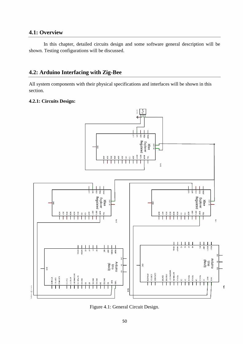
4.1: Overview
In this chapter, detailed circuits design and some software general description will be
shown. Testing configurations will be discussed.
4.2: Arduino Interfacing with Zig-Bee
All system components with their physical specifications and interfaces will be shown in this
section.
4.2.1: Circuits Design:
Figure 4.1: General Circuit Design.

51
4.2.2: Xbee Interface
The Xbee transceivers will be connected to two Arduino Uno microcontrollers.
Figure4.2shows the connection between Xbee transceiver and Arduino Uno microcontroller.
Figure 4.2: Xbee to Arduino Uno interface
Table 4.1: Pins connection for Figure 4.2
Xbee pin Arduino Uno pin
DIN TX
DOUT RX
52
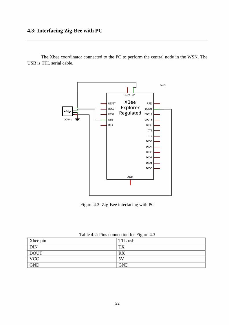
4.3: Interfacing Zig-Bee with PC
The Xbee coordinator connected to the PC to perform the central node in the WSN. The
USB is TTL serial cable.
Figure 4.3: Zig-Bee interfacing with PC
Table 4.2: Pins connection for Figure 4.3
Xbee pin TTL usb
DIN TX
DOUT RX
VCC 5V
GND GND

53
4.4: WSN Nodes Circuit Design
Figure 4.4: WSN node circuit design
The circuit above shows the detailed electronic circuit design for one node. Each node
consists of AT mega microprocessor, Xbee transceiver, motion sensor, smoke detector, pump,
regulators and relays.
54
Chapter 5: Software Design & Implementation
5.1 Overview
5.2 Arduino Software Programming
5.3 Android Mobile Application
5.4 C# Programming
5.5 Zig-Bee Network Implementation

55
5.1: Overview
In this chapter, we will show the implementation and programming of all system parts,
from System WSN Nodes (Sensors, Arduino Microcontrollers, Zig-Bee Units, security door, and
Pumps) to PC and mobile application.
5.2: Arduino Software Programming
The open source Arduino environment makes it easy to us to develop our system. Firstly,
we define the parameters of the WSN (motion sensor, fire sensor, pumps and doors).
Then, each parameter is set at a specific pin number weather it is an input or an output.
Figure 5.1 explain definitions and pin connections.
Figure 5.1: Definitions and Pin Connections
56
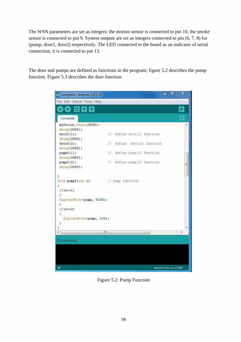
The WSN parameters are set as integers; the motion sensor is connected to pin 10, the smoke
sensor is connected to pin 9. System outputs are set as integers connected to pin (6, 7, 8) for
(pump, door1, door2) respectively. The LED connected to the board as an indicator of serial
connection, it is connected to pin 13.
The door and pumps are defined as functions in the program; figure 5.2 describes the pump
function. Figure 5.3 describes the door function.
Figure 5.2: Pump Function

57
Figure 5.3: Door Function
The door function explains (x) as variable parameter; if it equals (1) then door1and door2 are
activated ,but if it equals (2) then door1 and door2 are off .
Note: door2 is not implemented in our system; the code can be developed for number of sensors,
doors and pumps.

58
Finally, the program verified, and then uploaded to the Arduino board. Figure5.4 shows the steps
of compiling.
Figure 5.4: System Compiling
5.3: Android Mobile Application
We have designed Android application to control and monitor our system by using eclipse
program. Through this program, we can design interfaces capable of receiving and sending data.
Figure 5.5 shows the initial application interface, which includes specific information (such as
username and password) to increase the protection and prevent unauthorized people to use this
application

59
Figure 5.5: Initial Interface
The options interface in Figure 5.6 shows that t the user can choose the monitor or control
button, also it contain back button to move to initial interface.
Figure 5.6: Options Interface
We also tested the IP camera, and stream live video through the Wi-Fi network on PC and on
Smartphone using an Android application. By getting the static IP and port from camera, putting
it in those devices, then start streaming, as shown in the following figures:

61
Figure 5.7: Live Video Streaming
Figure 5.8: Inserting Settings on the Android Application

61
5.4: C# Programming
A C# program has the functionalities of controlling Security Door, Pumps, and the ability
of automatically sending notification messages to 3G modem depending on specific conditions of
Motion or Fire.
Here is the application graphical user interface:
Figure 5.9: C# program graphical user interface
The Connect button above opens the connection with WSN Nodes and 3G modem that
interfaced with PC COM ports, and that TextBox necessary to show information about each
process. We will show more about these buttons in chapter 6
Underneath this User Interface, there are codes for every button and label as follows:
1) This code opens ports with WSN Nodes and 3G modem

62
Figure 5.10: Open connection with 3G Modem
2) The following code has functionality of sending control signal to Security door.
Figure 5.11: Security Doors Controlling Code
3) The following code has functionality of sending control signals to the two Water Pumps
in the system.

63
Figure 5.12: Water Pumps Controlling Code

64
5.5: Zig-Bee Network Implementation
The zig-bee network testing done by X-CTU software, which is a configuration and test
utility software. Through a USB serial port, each Xbee unit will be connected to PC in order to set
each unit parameters
PC settings:
It allows selecting the desired COM port, and configuring that port. Figure 5.10 shows the
specific settings for each Xbee unit (baud rate, flow control, data bit, parity, stop bit).
Figure 5.13: Specific settings for each Xbee unit
In order to establish the testing configurations we use two Xbee units and two PC's. We
set each one as the destination of the other.

65
Figure 5.14: Xbee unit with MAC address
After setting the Xbee units, we have tried to send message from each on to the other .Figure
5.12 shows the text message (blue line: Transmit, red line: Receive)
Figure 5.15: Message between Zig-Bee Units

66
Chapter 6: Testing and Results
6.1 Overview
6.2 WSN Nodes
6.3 Door Prototype
6.4 Controlling with C#

67
6.1: Overview
In this chapter, we will show the testing and results of the system. The test of WSN and
the video streaming technique, also the door controlling using C# programming will be shown.
6.2: WSN nodes
The WSN in our project is an ad hoc network consists of three nodes:
Node A: Arduino, Xbee transceiver, motion sensor (1), smoke detector, water pump, and two
normally open relays connected to the door and other electronic components. As shown in figure
6.1
Node B: Arduino, Xbee transceiver, motion sensor (2), smoke detector, water pump and other
electronic components. As shown in figure 6.2
Central node: Xbee transceiver and Xbee USB dongle. Figure 6.3 shows the WSN that we
designed.
Figure 6.1: WSN Node A

68
Figure 6.2: WSN node B
Figure 6.3: All WSN nodes

69
Motion Sensor:
We use Honeywell Standard PIR IS215T motion sensor. Figure 6.4 shows the sensor connected
to the node. The range of this sensor is (8_12 meters).
Figure 6.4: Motion sensor connection with WSN node
Figure 6.5 shows the water pump connected to the node. This water pump usually used for car, but
we use it in our project as reuse of resources with least possible cost.
Figure 6.5: Water Pump connected to WSN node

71
Smoke sensor:
We use MQ2 smoke sensor. Figure 6.6 shows the sensor connected to the node.it has a good
sensitivity to combustible gas in wide range.
Figure 6.6: Smoke Sensor connection with WSN node
6.3: Door Prototype:
We design this door prototype by using CD–ROM in order to open and close it. Figure 6.7 shows
the inside and outside view of it.
Figure 6.7: Door Prototype

71
We connected the door with the node A, to open or close it, as shown in Figure 6.8
Figure 6.8: Door Model connected to WSN node A
6.4: Controlling with C#
Control feature is one of the major parts of PC program, using our C# program we can
control security door as well as water pumps. In order to send controlling signals to these devices,
we need to set connection with WSN then enabling control buttons to send these signals.
The following steps shows the process:

72
1) Connecting to WSN central node through pre-set COM port, so that word (+ZPSTM:)
means that the connection was successful.
Figure 6.9: Server Connection with WSN
2) Controlling water pumps and security door, each with specific button.
Figure 6.10: Controlling using Server

73
Chapter 7: Conclusion
7.1 Overview
7.2 Achievements
7.3 Conclusion
7.4 Future Work

74
7.1: Overview
In this chapter, we will discuss what we achieved in this project, overall conclusion, and
future work suggestions and recommendations for even better implementation.
7.2: Achievements
Through past months, we achieve different points according to our project plan:
Implementing a small sized electronic nodes
Building an android mobile application for security notifications, accepted delay live
video streaming viewing (monitoring), and controlling camera, pumps, and security door
with a simple designed user interface.
Building a specific PC program based on C# language with controlling functions for
pumps and security door, and automatically sending alarm messages to mobile phone
depending on motion or fire events. This program has simple and effective user interface
as well.
Implementing suitable door model for our project.
7.3: Conclusion
At the end of our project, we conclude some ideas as follows:
Working with a team is very important thing, and give a power and meaning to the project.
The fact that four students in this project helped everyone in his/her project load, because of
cooperation of different suggestions, and ideas and solutions that taken from everyone in our
group, and this help us a lot especially when we faced some challenges. Because of that
cooperation, our project succeed.
Video Streaming is one of the widely used techniques for many useful applications, in our
project; we use video streaming to increase security protection for the building using IP camera
that streams the live video to the Android mobile application using streaming protocol http, over
TCP/IP. Video LAN VLC media player helped as a lot in this segment of the project, because it
has streaming capability over many protocols.

75
An Open source android program is the more effective solution for developing mobile
application for our project. We have learned many things about android programming while
building the application, from dealing with Activities to designing the user interface.
Using C# to program the PC, because it fully featured and smooth on windows
environment, so we build our monitoring and surveillance program using this programming
language.
Arduino Microcontroller is very useful and simple than other microcontrollers, especially
for controlling such devices, inputs, outputs, and the capability of interfacing with wide variety of
transceivers such as Zig-Bee. We learned to program Arduino and connect it with different
electronics and devices.
The high data rate and the wide coverage of the third generation cellular system is very
important to achieve mobility in our project. Third generation modem stick interfaced with PC
used in our project to send and receive data from mobile device over cellular network.
7.4: Future Work
We hope that our project will be a valuable and useful reference for other future projects
related to smart security systems.
In our project, we focus on WSN that uses safety and security sensors to protect the
building, other projects can use the same system topology for other purposes .For example: power
efficient, lighting systems.
One of the most important goals of our project is to use the techniques of communications that
we learned in our university study. Other future techniques might be useful for higher accuracy
and efficiency.
Finally, the system can be implemented in companies and other Institutions by increasing the
number of nodes fitting the building’s shape.

#include <SoftwareSerial.h>
SoftwareSerial mySerial(2, 3); // RX, TX
int motion =10; // motion sensor at pin 10
int smoke=9; //smoke sensor at pin 9
int pump=6; //water pump at pin 6
int door1=7; //door1 at pin 7
int door2=8; //door2 at pin 8
int led=13; //led(indicator)at pin 13
// the setup routine runs once when you press reset:
void setup()
pinMode(motion,INPUT); // motion sensor digital value as input
pinMode(smoke,INPUT); // smoke sensor digital value as input
pinMode(pump,OUTPUT); // water pump digital value as output
pinMode(door1,OUTPUT); //door1 digital value as output
pinMode(door2,OUTPUT); //door2 digital value as output
pinMode(led,OUTPUT); //indicator for zigbee setup
Serial.begin(9600); // initialize serial communication at 9600 bits per second
mySerial.begin(9600);
delay(2000);
doorf(1); // define door(1) function
delay(2000);
doorf(2); // define door(2) function
delay(2000);
pumpf(1); // define pump(1) function

delay(2000);
pumpf(2); // define pump(2) function
delay(2000);
void pumpf(int x) // pump function
if(x==1)
digitalWrite(pump, HIGH);
if(x==2)
digitalWrite(pump, LOW);
void doorf(int x) //door function
if(x==1)
digitalWrite(door1, HIGH);
digitalWrite(door2, LOW);
delay(1500);
digitalWrite(door2, LOW);
digitalWrite(door1, LOW);
delay(500);
else if(x==2)

digitalWrite(door1, LOW);
digitalWrite(door2, HIGH);
delay(1500);
digitalWrite(door2, LOW);
digitalWrite(door1, LOW);
delay(500);
void loop()
int red;
if (mySerial.available()) //verify the serial connection
red=mySerial.read(); //read data from serial connection
if(red=='R')doorf(1);
if(red=='r')doorf(2);
if(red=='U')pumpf(1);
if(red=='u')pumpf(2);
if(digitalRead(motion)==HIGH)
mySerial.print("*A>M#"); //print at the serial port
delay(5000);

if(digitalRead(smoke)==LOW)
mySerial.print("*A>S#");
pumpf(1);
delay(5000);

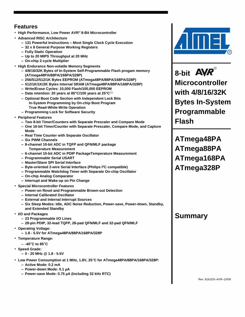
Features • High Performance, Low Power AVR® 8-Bit Microcontroller • Advanced RISC Architecture
– 131 Powerful Instructions – Most Single Clock Cycle Execution – 32 x 8 General Purpose Working Registers – Fully Static Operation – Up to 20 MIPS Throughput at 20 MHz – On-chip 2-cycle Multiplier
• High Endurance Non-volatile Memory Segments – 4/8/16/32K Bytes of In-System Self-Programmable Flash progam memory
(ATmega48PA/88PA/168PA/328P) – 256/512/512/1K Bytes EEPROM (ATmega48PA/88PA/168PA/328P) – 512/1K/1K/2K Bytes Internal SRAM (ATmega48PA/88PA/168PA/328P) – Write/Erase Cycles: 10,000 Flash/100,000 EEPROM – Data retention: 20 years at 85°C/100 years at 25°C(1) – Optional Boot Code Section with Independent Lock Bits
In-System Programming by On-chip Boot Program True Read-While-Write Operation
– Programming Lock for Software Security • Peripheral Features
– Two 8-bit Timer/Counters with Separate Prescaler and Compare Mode – One 16-bit Timer/Counter with Separate Prescaler, Compare Mode, and Capture
Mode – Real Time Counter with Separate Oscillator – Six PWM Channels – 8-channel 10-bit ADC in TQFP and QFN/MLF package
Temperature Measurement – 6-channel 10-bit ADC in PDIP PackageTemperature Measurement – Programmable Serial USART – Master/Slave SPI Serial Interface – Byte-oriented 2-wire Serial Interface (Philips I2C compatible) – Programmable Watchdog Timer with Separate On-chip Oscillator – On-chip Analog Comparator – Interrupt and Wake-up on Pin Change
• Special Microcontroller Features – Power-on Reset and Programmable Brown-out Detection – Internal Calibrated Oscillator – External and Internal Interrupt Sources – Six Sleep Modes: Idle, ADC Noise Reduction, Power-save, Power-down, Standby,
and Extended Standby • I/O and Packages
– 23 Programmable I/O Lines – 28-pin PDIP, 32-lead TQFP, 28-pad QFN/MLF and 32-pad QFN/MLF
• Operating Voltage: – 1.8 - 5.5V for ATmega48PA/88PA/168PA/328P
• Temperature Range:
– -40°C to 85°C • Speed Grade:
– 0 - 20 MHz @ 1.8 - 5.5V
• Low Power Consumption at 1 MHz, 1.8V, 25°C for ATmega48PA/88PA/168PA/328P: – Active Mode: 0.2 mA – Power-down Mode: 0.1 µA – Power-save Mode: 0.75 µA (Including 32 kHz RTC)
8- bit
Microcontroller
with 4/8/16/32K
Bytes In-Syste m
Programmable
Flash
ATmega48PA
ATmega88PA
ATmega168PA
ATmega328P
Summary
Rev. 8161DS–AVR–10/09
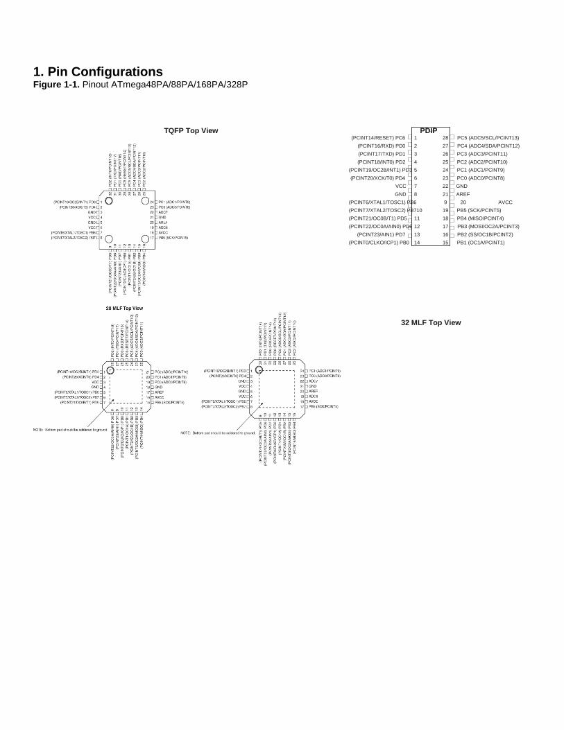
1. Pin Configurations Figure 1-1. Pinout ATmega48PA/88PA/168PA/328P
TQFP Top View PDIP (PCINT14/RESET) PC6 1 28 PC5 (ADC5/SCL/PCINT13)
(PCINT16/RXD) PD0 2 27 PC4 (ADC4/SDA/PCINT12) (PCINT17/TXD) PD1 3 26 PC3 (ADC3/PCINT11) (PCINT18/INT0) PD2 4 25 PC2 (ADC2/PCINT10) (PCINT19/OC2B/INT1) PD3 5 24 PC1 (ADC1/PCINT9) (PCINT20/XCK/T0) PD4 6 23 PC0 (ADC0/PCINT8) VCC 7 22 GND GND 8 21 AREF (PCINT6/XTAL1/TOSC1) PB6 9 20 AVCC (PCINT7/XTAL2/TOSC2) PB710 19 PB5 (SCK/PCINT5) (PCINT21/OC0B/T1) PD5 11 18 PB4 (MISO/PCINT4) (PCINT22/OC0A/AIN0) PD6 12 17 PB3 (MOSI/OC2A/PCINT3) (PCINT23/AIN1) PD7 13 16 PB2 (SS/OC1B/PCINT2) (PCINT0/CLKO/ICP1) PB0 14 15 PB1 (OC1A/PCINT1)
32 MLF Top View

77
Appendix A
ATmega 328 Microcontroller
Data Sheet

80
Appendix B
Motion sensor
Honeywell Standard PIR
Data sheet

83
Appendix C
Smoke Sensor MQ-2
Data sheet

88
Appendix D
Arduino Uno Code

IS215T
The IS215T is an entry level passive infrared motionsensor. Dip switch setting, a large wiring channel and mountingflexibility make the IS215T easy to install.
Compromising the IS215T is inhibited by the look-downzones, tamper switch, sabotage-resistant lens designand the magnet-proof relay.All these factors make the IS215T an ideal sensor forresidential and light commercial applications.
PIR motion sensor
Features:
Cannot be compromised by a
magnet
Dip switches for easy setting of
parameters
Improved RF immunity
Large wiring channel on back to
allow surface wiring
Patented look-down mirror
provides optimum detection
directly beneath the sensor
Wall-mount and corner mount
knockouts provides mounting
flexibility
Sabotage-resistant lens design
Selectable sensitivity
Tamper switch: activates before access
to the circuitry is possible
White Light Immunity of minimum
6500 Lux reduces the chance of
false activiation
Bug guard prevents insects access to
the sensor optics which reduces the
chance of false activation
Designed for residential and light
commercial applications
Silent relay allows for use in quiet
environments

HSC-IS215T-02-EN(1008)DS-ZOctober 2008 © 2008 Honeywell International Inc.
IS215TPIR motion sensor
Detection Patterns:
Accessories:SMB10 White swivel mount bracket (5 pack)
SMB10C White ceiling mount bracket (5 pack)
SMB10T Tampered white swivel mount bracket (5 pack)
Ordering:
IS215T Passive infrared motion sensor
Agency Listings:CE
Honeywell reserves the right to alterthe specification of products withoutprior notice
Top View
Side View
SpecificationsDetection method Dual element passive infrared
Range 12 x 12 m
Detection zones44 long range, 14 intermediate, 8 lower
and 4 look-down
PIR sensitivity Low (3-5 steps) and High (1-3 steps) by dipswitch
LED enable By dipswitch
Mounting height 2.3 to 2.7 m
Power requirements 10 - 14 Vdc, 7 mA @ 12 Vdc
Alarm relayForm A (NC) / 90 mA@16 Vdc, max. 40 Ohm
protective resistor
Tamper switch 500 mA @ 30 Vdc
Operating temperature -10oC to +55oC
Relative humidity 5% - 95% non condensing
RF Immunity 30 V/m from 10 to 1000 MHz
White Light Immunity Better than 6500 Lux
Dimensions 86 x 60 x 38 mm. (HxWxD)
Weight 67g.
Honeywell Security Newhouse Industrial EstateMotherwellLanarkshireML1 5SBScotlandTel :+44 (0) 1698 738200Fax : +44 (0) 1698 738300www.honeywell.com/security/uk
Look down intermediate long
Lower
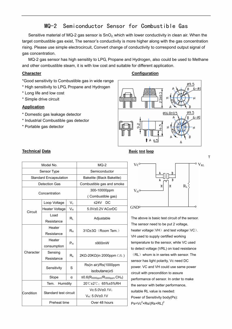
MQ-2 Semiconductor Sensor for Combustible Gas
Sensitive material of MQ-2 gas sensor is SnO2, which with lower conductivity in clean air. When the target combustible gas exist, The sensor’s conductivity is more higher along with the gas concentration rising. Please use simple electrocircuit, Convert change of conductivity to correspond output signal of gas concentration.
MQ-2 gas sensor has high sensitity to LPG, Propane and Hydrogen, also could be used to Methane and other combustible steam, it is with low cost and suitable for different application.
Character Configuration
*Good sensitivity to Combustible gas in wide range * High sensitivity to LPG, Propane and Hydrogen * Long life and low cost * Simple drive circuit
Application
* Domestic gas leakage detector * Industrial Combustible gas detector * Portable gas detector Technical Data Basic test loop
T
The above is basic test circuit of the sensor.
The sensor need to be put 2 voltage,
heater voltage(VH) and test voltage(VC).
VH used to supply certified working
temperature to the sensor, while VC used
to detect voltage (VRL) on load resistance
(RL)whom is in series with sensor. The
sensor has light polarity, Vc need DC
power. VC and VH could use same power
circuit with precondition to assure
performance of sensor. In order to make
the sensor with better performance,
suitable RL value is needed:
Power of Sensitivity body(Ps):
Ps=Vc2×Rs/(Rs+RL)2
Model No. MQ-2
Sensor Type Semiconductor
Standard Encapsulation Bakelite (Black Bakelite)
Detection Gas Combustible gas and smoke
Concentration 300-10000ppm
( Combustible gas)
Loop Voltage Vc ≤24V DC
Heater Voltage VH 5.0V±0.2V ACorDC Circuit
Load
Resistance RL Adjustable
Heater
Resistance RH 31Ω±3Ω(Room Tem.)
Heater
consumption PH ≤900mW
Sensing
Resistance Rs 2KΩ-20KΩ(in 2000ppm C3H8 )
Sensitivity S Rs(in air)/Rs(1000ppm
isobutane)≥5
Character
Slope α ≤0.6(R5000ppm/R3000ppm CH4)
Tem. Humidity 20±2;65%±5%RH
Standard test circuit Vc:5.0V±0.1V;
VH: 5.0V±0.1V Condition
Preheat time Over 48 hours
Vc
VH
GND
RL
VRL

Resistance of sensor(Rs): Rs=(Vc/VRL-1)×RL
Sensitivity Characteristics Influence of Temperature/Humidity
Fig.1 shows the typical sensitivity characteristics of Fig.2 shows the typical temperature and humidity
the MQ-2, ordinate means resistance ratio of the sensor characteristics. Ordinate means resistance ratio
(Rs/Ro), abscissa is concentration of gases. Rs means of the sensor (Rs/Ro), Rs means resistance of sensor
resistance in different gases, Ro means resistance of in 1000ppm Butane under different tem. and humidity.
sensor in 1000ppm Hyrogen. All test are under standard Ro means resistance of the sensor in environment of
test conditions. 1000ppm Methane, 20/65%RH
Structure and configuration
Structure and configuration of MQ-2 gas sensor is shown as Fig. 3, sensor composed by micro AL2O3 ceramic tube, Tin
Dioxide (SnO2) sensitive layer, measuring electrode and heater are fixed into a crust made by plastic and stainless steel
net. The heater provides necessary work conditions for work of sensitive components. The enveloped MQ-2 have 6 pin, 4
of them are used to fetch signals, and other 2 are used for providing heating current.
Fig1
0.5
0.7
0.9
1.1
1.3
1.5
1.7
1.9
-20 -10 0 10 20 30 40 50
Rs/
R0
60%RH
30%RH
85%RH
Fig2

Notification 1 Following conditions must be prohibited 1.1 Exposed to organic silicon steam
Organic silicon steam cause sensors invalid, sensors must be avoid exposing to silicon bond, fixature, silicon latex, putty or plastic contain silicon environment 1.2 High Corrosive gas
If the sensors exposed to high concentration corrosive gas (such as H2Sz, SOX,Cl2,HCl etc), it will not only result in corrosion of sensors structure, also it cause sincere sensitivity attenuation. 1.3 Alkali, Alkali metals salt, halogen pollution
The sensors performance will be changed badly if sensors be sprayed polluted by alkali metals salt especially brine, or be exposed to halogen such as fluorin. 1.4 Touch water
Sensitivity of the sensors will be reduced when spattered or dipped in water. 1.5 Freezing
Do avoid icing on sensor’surface, otherwise sensor would lose sensitivity. 1.6 Applied voltage higher
Applied voltage on sensor should not be higher than stipulated value, otherwise it cause down-line or heater damaged, and bring on sensors’ sensitivity characteristic changed badly. 1.7 Voltage on wrong pins
For 6 pins sensor, if apply voltage on 1、3 pins or 4、6 pins, it will make lead broken, and without signal when apply on 2、4 pins 2 Following conditions must be avoided 2.1 Water Condensation
Indoor conditions, slight water condensation will effect sensors performance lightly. However, if water condensation on sensors surface and keep a certain period, sensor’ sensitivity will be decreased.
2.2 Used in high gas concentration
No matter the sensor is electrified or not, if long time placed in high gas concentration, if will affect sensors characteristic.
2.3 Long time storage
The sensors resistance produce reversible drift if it’s stored for long time without electrify, this drift is related with storage conditions. Sensors should be stored in airproof without silicon gel bag with clean air. For the sensors with long time storage but no electrify, they need long aging time for stbility before using.
2.4 Long time exposed to adverse environment
No matter the sensors electrified or not, if exposed to adverse environment for long time, such as high humidity, high temperature, or high pollution etc, it will effect the sensors performance badly.
2.5 Vibration
Continual vibration will result in sensors down-lead response then repture. In transportation or assembling line, pneumatic screwdriver/ultrasonic welding machine can lead this vibration.
2.6 Concussion
If sensors meet strong concussion, it may lead its lead wire disconnected.
2.7 Usage For sensor, handmade welding is optimal way. If use wave crest welding should meet the following
conditions: 2.7.1 Soldering flux: Rosin soldering flux contains least chlorine 2.7.2 Speed: 1-2 Meter/ Minute 2.7.3 Warm-up temperature:100±20 2.7.4 Welding temperature:250±10 2.7.5 1 time pass wave crest welding machine
If disobey the above using terms, sensors sensitivity will be reduced.

76
References
[1] M.Alsharawi, S. Suliman, T. Abu Zahra ," Smart Farm", Bachelor project dissertation,
Palestine Polytechnic University ,Hebron , Jun 2013.
[2] Huiping Huang, Shide Xiao, XiangyinMeng, Ying Xiong. "A Remote Home Security System
Based on Wireless Sensor Network and GSM Technology", paper Southwest Jiaotong
University, Chengdu, China, 2010.
[3] Sajidullah S. Khan, AnujaKhoduskar, Dr. N. A. Koli, "Home Automation System",
International Journal of Advanced Engineering Technology 46, pp.128-148, 2011.
[4] Hamza Abu Ajamia, Fouad Abu Eisheh, Sara Haddad, Amnah Almasri," Building
Management System ", Bachelor project dissertation, Hebron: Palestine polytechnic University
2012.
[5] Ummi kalsom Binti Noor Din, "Alarm System Using Body Detector", Bachelor project
dissertation, Faculty of Electrical & Electronics Engineering, Malaysia Pahang University, Nov
2008.
[6] Introduction to Wi-Fi networks, Advantages and Limitations of Wi-Fi, white paper,
http://www.crutchfield.com/SWjrNF1g5oYG/learn/learningcenter/home/wifi.html
[7] Specifications of wireless IP camera, white paper,
http://www.broadbandbuyer.co.uk/Shop/ShopSearch.asp?CategoryID=687
[8] Drew Gislson, "Zigbee wireless networking- Zigbee specification types and topology ",
Elsevier Inc., Burlington, MA, 2008.
[9] Korhonen, Juha,"Introduction to 3G mobile communication", 2nd Edition, Artech House Inc.
Norwood, MA, 2003.
[10]Main characteristic, advantages and disadvantages of the 3G technology, white paper
http://www.itmindia.edu/images/ITM/pdf/3G%20Technology.pdf
[11] 3G modem description, white paper,
http://denmasbroto.com/article-8-3g-modem-connections.html
[12] Definition of a microcontroller and the type of it, white paper .
http://www.futureelectronics.com/en/microcontrollers/microcontrollers.aspx

76
[13] Alan G. Smith," Introduction to Arduino", CreateSpace Independent Publishing Platform,
August 30, 2011.
[14] Joseph M. Fleming," Smoke Detector Technology and the Investigation of Fatal Fires ",
Deputy Chief/Fire Marshal, Boston Fire Department, Boston, MA.
[15] Definition and types of pump, white paper,
http://www.rpi.edu/dept/chem-eng/Biotech-Environ/PUMPS/intro.html
[16] Jon S. Wilson, "Sensor Technology-Motion sensor", Elsevier Inc., 2005.
[17] PIR motion sensor, definition and principle, white paper,
http://www.ladyada.net/learn/sensors/pir.html
[18] Introduction, applications and architecture of Android, white paper,
http://shrikantandroidinfo.blogspot.com/2013/01/android-architecture.html.
[19] Video Surveillance Bandwidth Requirements - Calculation of Utilization, white paper,
http://www.mistralsolutions.com/hs-downloads/tech-briefs/jul09-article-1.html
[20] H.264 Compression, conclusion, white paper,
http://www.imakenews.com/kin2/e_article001550736.cfm?x=b11,0,w
[21] HSDPA (High-Speed Downlink Packet Access), white paper,
http://www.gsmarena.com/glossary.php3?term=hsdpa