Embed Size (px)
Citation preview
HANOI UNIVERSITY OF SCIENCE AND TECHNOLOGY
SCHOOL OF MATERIALS SCIENCE AND ENGINEERING ------o0o------
GRADUATION THESIS
Student: Vu Dinh Thang
Class: Materials Science Engineering, Advanced Program
Student ID: 20113349
Course: K56
Advisor: Assoc. Prof. Le Thai Hung
Hanoi, 2016
Vũ
Đìn
h T
hắn
g
R
esea
rch,
des
ign
, fa
bri
cate
ele
ctr
ical
so
cket
co
ver
by
usi
ng
SM
C m
ater
ials
2
01
4, Ju
ne
HANOI UNIVERSITY OF SCIENCE AND TECHNOLOGY
SCHOOL OF MATERIALS SCIENCE AND ENGINEERING ------o0o------
GRADUATION THESIS
“RESEARCH, DESIGN AND FABRICATE ELECTRICAL
SOCKET COVERS BY USING POLYMER MATRIX
COMPOSITE WITH GLASS FIBER REINFORCEMENT
(SMC)”
Student: Vu Dinh Thang
Class: Materials Science Engineering, Advanced Program
Student ID: 20113349
Course: K56
Advisor: Assoc. Prof. Le Thai Hung
Hanoi, 2016
MINISTRY OF EDUCATION AND TRAINING
HANOI UNIVERSITY OF SCIENCE AND
TECHNOLOGY
.................................................
SOCIALISTS REPUBLIC OF VIETNAM
Independence – Freedom – Happiness
…………………........
Student‟s name: Vu Dinh Thang
Student ID: 20113349
Course: K56
Major: Materials Science Engineering
1. Topic
Research, design, fabricate electrical socket covers by using polymer matrix
composite with glass fiber reinforcement (SMC)
Initial data:
Sheet molding compound materials
Graduation thesis “research about rheological behavior of SMC materials” of
Nguyen Quy Dat – student at School of Materials Science and Technology
2. Content:
Theoretical overview
Design electrical socket cover mold
Simulate compression process
Experimental fabricate electrical socket covers
Test and analyze mechanical, thermal and electrical properties of the products.
Advisor‟s signature
Hanoi University of Science and Technology Graduation thesis
Vu Dinh Thang, MSE-K56 Page 4
CONTENTS
LIST OF FIGURES ........................................................................................................... 6
LIST OF TABLES ............................................................................................................. 8
ABSTRACT ....................................................................................................................... 9
ACKNOWLEDGMENT ................................................................................................. 10
CHAPTER 1: THEORETICAL OVERVIEW ............................................................. 11
1.1 Overview of the research process ........................................................................ 11
1.1.1 Research purposes ......................................................................................... 11
1.1.2 Research methodology and approach ........................................................... 11
1.2 Definition and classification of composite materials ........................................... 11
1.2.1 Definition of composite materials ................................................................. 11
1.2.2 Properties of composite materials ................................................................. 12
1.2.3 Classification of composite materials ........................................................... 12
1.3 Overview of polymer matrix composite .............................................................. 14
1.3.1 Definition ...................................................................................................... 14
1.3.2 Properties ....................................................................................................... 15
1.3.3 Classification ................................................................................................. 15
1.4 Overview of SMC composite materials ............................................................... 15
1.4.1 Definition of SMC composite materials ....................................................... 15
1.4.2 Matrix polymer of SMC composite materials ............................................... 15
1.4.3 Reinforcement ............................................................................................... 17
1.4.4 Properties of SMC materials ......................................................................... 18
1.5 Fabricating SMC materials .................................................................................. 20
1.6 Applications of SMC materials ............................................................................ 23
1.7 History and current research about SMC materials ............................................. 24
1.8 Summary .............................................................................................................. 27
CHAPTER 2: DESIGNING THE MOLD AND SIMULATING COMPRESSION
PROCESS ......................................................................................................................... 28
2.1 Overview about compression molding ................................................................ 28
2.2 Technical demands of a compression mold ......................................................... 29
Hanoi University of Science and Technology Graduation thesis
Vu Dinh Thang, MSE-K56 Page 5
2.3 Mold manufacturing process................................................................................ 29
2.4 Designing on Solidworks software ...................................................................... 29
2.4.1 Introduction of Solidworks software ............................................................. 29
2.4.2 Mold designing steps ..................................................................................... 30
2.5 Introduction of Deform 3D software ................................................................... 32
2.6 Technical specifications and simulation process ................................................. 32
2.6.1 Simulation steps ............................................................................................ 32
2.6.2 Behavior model of fabricated sheet molding composite ............................... 38
2.6.3 Boundary conditions ..................................................................................... 39
2.6.4 Simulation results .......................................................................................... 40
2.7 Summary .............................................................................................................. 41
CHAPTER 3: FABRICATING ELECTRICAL SOCKET COVER ......................... 42
3.1 Manufacturing the electrical socket cover mold .................................................. 42
3.2 Introduction about equipment .............................................................................. 43
3.3 Material demands of the compression process .................................................... 45
3.4 Technical modes of the compression process ...................................................... 46
3.5 Fabricating electrical socket cover process ......................................................... 50
3.6 Summary .............................................................................................................. 52
CHAPTER 4: TESTING AND ANALYZING PROPERTIES OF ELECTRICAL
SOCKET COVER ........................................................................................................... 53
4.1 Testing mechanical, thermal and electrical properties methods .......................... 53
4.1.1 Testing compressive strength method ........................................................... 53
4.1.2 Testing flexural modulus method.................................................................. 53
4.1.3 Measuring thermal resistance method ........................................................... 54
4.1.4 Measuring breakdown voltage ...................................................................... 55
4.1.5 Measuring surface resistor ............................................................................ 55
4.2 Mechanical, thermal, electrical properties of the socket products ....................... 56
CONCLUSIONS .............................................................................................................. 60
REFERENCES ................................................................................................................ 61
APPENDIX....................................................................................................................... 62
Hanoi University of Science and Technology Graduation thesis
Vu Dinh Thang, MSE-K56 Page 6
1 LIST OF FIGURES
Figure 1.1: The classification of composite materials based on reinforcement phase ...... 13
Figure 1.2: The classification of composite materials based on matrix phase .................. 14
Figure 1.3: A representative unsaturated (ortho) polyester resin ...................................... 16
Figure 1.4: Oversimplified scheme of a typical compounding line (paste mixing + SMC
machine). ........................................................................................................................... 20
Figure 1.5: Photograph showing chopped glass fiber bundles falling onto the lower paste
film ..................................................................................................................................... 22
Figure 1.6: Applications of SMC composite materials ..................................................... 24
Figure 1.7: Assumption of composite materials in the world ........................................... 25
Figure 1.8: Assumption of composite materials in Vietnam ............................................. 25
Figure 2.1: Compression mold of sheet molding composite materials ............................. 28
Figure 2.2: A Solidworks drawing of electrical socket cover ........................................... 30
Figure 2.3: An electrical socket covert. ............................................................................. 30
Figure 2.4: A 3D model of the socket cover mold. ........................................................... 31
Figure 2.5a: a model 3D of bottom mold .......................................................................... 31
Figure 2.5 b: a model 3D of top mold. .............................................................................. 31
Figure 2.6: A model of complete mold ............................................................................. 32
Figure 2.7: Import Geometry command ............................................................................ 34
Figure 2.8: Insert a behavior model of material ................................................................ 35
Figure 2.9: Mesh for work piece ....................................................................................... 35
Figure 2.10: Movement command .................................................................................... 36
Figure 2.11: Set up temperature ........................................................................................ 36
Figure 2.12: Set up friction coefficient.............................................................................. 37
Figure 2.13: Set up steps for simulation problem ............................................................. 37
Figure 2.14: Database generation command ..................................................................... 38
Figure 2.15: Simulation results .......................................................................................... 38
Figure 2.16: Stress- strain curve of fabricated SMC materials. ........................................ 39
Figure 3.1 (a): A top die of electrical socket cover mold .................................................. 42
Hanoi University of Science and Technology Graduation thesis
Vu Dinh Thang, MSE-K56 Page 7
Figure 3.1(b): A bottom die of electrical socket cover mold ............................................ 42
Figure 3.2: Hydraulic vertical press .................................................................................. 43
Figure 3.3: System of mold heating .................................................................................. 43
Figure 3.4: Rod resistors .................................................................................................... 44
Figure 3.5: Thermocouples ................................................................................................ 44
Figure 3.6: Thermal resistant plates .................................................................................. 45
Figure 3.7 (a): Grease ........................................................................................................ 45
Figure 3.7 (b): Silicone release agent ................................................................................ 45
Figure 3.8: The second compression result ....................................................................... 47
Figure 3.9: the third compression result ............................................................................ 48
Figure 3.10: The fouth compression result ........................................................................ 49
Figure 3.11: The fifth compression result ......................................................................... 49
Figure 4.1: MTS 809 axial/ torsional testing machine 100kN .......................................... 53
Figure 4.2: Three points bending flexural test .................................................................. 54
Figure 4.3: Thermometer machine US 450 ....................................................................... 55
Figure 4.4: high voltage one direction testing machine model Phenix 4100-10. .............. 55
Figure 4.5: Surface resistor measuring machine ............................................................... 56
Figure 4.6: Stress- strain curve of an socket cover product. ............................................. 57
Hanoi University of Science and Technology Graduation thesis
Vu Dinh Thang, MSE-K56 Page 8
LIST OF TABLES
Table 1.1: Typical properties of different glass fibers ..................................................... 18
Table 1.2: Typical properties of SMC ............................................................................... 20
Table 2.1: Boundary conditions of simulation problem .................................................... 40
Table 2.2: Simulation results of three boundary conditions .............................................. 41
Table 3.1: the compositions of SMC material ................................................................... 46
Table 3.2: Technical modes of compression process ........................................................ 46
Table 4.1: Flexural strength of the products ...................................................................... 57
Table 4.2: Compression strength of the products .............................................................. 58
Table 4.3: Thermal resistance, break down voltage and surface resistor of the products . 58
Table 4.4: Comparison some properties between manufactured products and standard
properties of SMC materials .............................................................................................. 59
Hanoi University of Science and Technology Graduation thesis
Vu Dinh Thang, MSE-K56 Page 9
ABSTRACT
In recent years, science and technology in the world is growing greatly, especially in
the study of new materials because of their wide applications in many fields of life. The
highlight is introduction and development of polymer composite materials. Polymer
composite materials have many advanced properties as well as applied widely in real life
such as light, stability, wear resistance, long life cycle, and etc. With many progressive
properties, they will gradually replace traditional materials like steel, iron, wood in all of
our life. Despite this, in Vietnam, polymer composite materials still remain relatively
extraneous to domestic industries because of a shortage in science and technology.
One of the most recently popular polymer composite types is sheet molding
composite material (SMC). The sheet molding composite materials (SMC) is a thermoset
polymer matrix composite, and is usually fabricated by hot compression molding method.
Graduation thesis: “research, design and fabricate electrical socket cover by using
polymer matrix composite with glass fiber reinforcement (SMC)” will contribute to the
research and development of sheet molding composite in Vietnam. This research will
focus on process of fabricating composite materials SMC as well as manufacturing a
practical application of SMC in electrical industry – electrical socket cover. Besides, the
mechanical, thermal and electrical properties of products are evaluated and investigated in
order to satisfy technical requirements in the electrical industry.
Keywords: Sheet molding compounds (SMC), polymer matrix composite, and glass
fiber, electrical socket cover.
Hanoi University of Science and Technology Graduation thesis
Vu Dinh Thang, MSE-K56 Page 10
ACKNOWLEDGMENT
This project would not have been possible without the support of many people. I
would like to express my gratitude to my professors at School of Materials Science and
Engineering, Hanoi University of Science and Technology, my advisors Associate
Professor Dr. Le Thai Hung for their support and supervision in orienting studies at
HUST and conducting this research.
Particular thanks go Associate Professor Dr. Le Thai Hung for his valuable
comments and helpful advice, scientific guidance and electrical socket cover valuable
feedback throughout the time at HUST, especially with my work.
I would also like to extend my appreciation and gratitude to the Laboratory of
Mechanical Testing Properties and National Key Laboratory for Polymer and Composite
Materials for helping me to carry on some experiments in their laboratories.
Finally, I wish to express my special thanks to my family for their great
encouragement throughout my project and thesis, as well as my friends for their continual
support and encouragement.
Hanoi, June 2016
Student
Vu Dinh Thang
Hanoi University of Science and Technology Graduation thesis
Vu Dinh Thang, MSE-K56 Page 11
CHAPTER 1
THEORETICAL OVERVIEW
1.1 Overview of the research process
1.1.1 Research purposes
Manufacturing successfully electrical socket cover made from sheet molding
composite materials.
Investigating mechanical properties of sheet molding composite materials in order
to satisfy the demands of manufacturing these products.
Applying simulation tools such as Solidworks, Deform3D to fabricate electrical
socket cover.
Testing mechanical, electrical properties of socket cover products.
1.1.2 Research methodology and approach
1.1.2.1 Research methodology
This research is based on combination of theoretical basics with deformation
simulation process and experimental methodology.
- Theoretical basics about materials: based on the mechanical, chemical
properties of sheet molding composite materials.
- Simulating compression molding process of electrical socket cover on Deform
3D software and then determining the technological parameters and molding
specifications.
- Practical methodology: manufacturing electrical socket cover and testing
mechanical properties of these products.
1.1.2.2 Research content
- Design and manufacture a compression mold to produce electrical socket cover.
- Simulate the mold filling of products by using Deform3D software.
- Manufacture electrical socket cover in a compression mold
- Test and analyze mechanical, electrical and thermal properties of products which is
manufactured; and compared to practical demands.
1.2 Definition and classification of composite materials
1.2.1 Definition of composite materials
Many of our modern technologies require materials with unusual combinations of
properties that cannot be met by the conventional metal alloys, ceramics, and polymeric
Hanoi University of Science and Technology Graduation thesis
Vu Dinh Thang, MSE-K56 Page 12
materials. This is especially true for materials that are needed for aerospace, underwater,
and transportation applications. For example, recently, aerospace engineers are
increasingly searching for new advanced materials that have low densities, are strong,
impact resistant, and are not easily corroded. Frequently, strong materials are relatively
dense; also, increasing the strength or stiffness generally results in a decrease in impact
strength.
Material property combinations and ranges have been, and are yet being, extended
by the development of composite materials. Generally speaking, composite materials are
combination of two or more constituent materials with significantly distinct properties in
order to produce new materials with aggregate performance exceeding that of its
components.
1.2.2 Properties of composite materials
The technological and commercial interest in composite materials derives from the
fact that their properties are not just different from their components but are often far
superior. Some of the possibilities include:
Composites can be designed that are very strong and stiff, yet very light in weight,
giving them strength to-weight and stiffness-to-weight ratios several times greater than
steel or aluminum. These properties are highly desirable in applications ranging from
commercial aircraft to sports equipment.
Fatigue properties and toughness are generally better than for the common
engineering metals. Furthermore, composites can be designed that do not corrode like
steel in order to apply in maritime industries.
With composite materials, it is possible to achieve combinations of properties not
attainable with metals, ceramics, or polymers alone.
Better appearance and control of surface smoothness are possible with certain
composite materials.
1.2.3 Classification of composite materials
Many composite materials are usually composed of just two phases; one term is the
matrix, which is continuous and surrounded the other phase, often called the
reinforcement because it usually serves to strengthen the composite. The properties of
composites are a function of the properties of the constituent phases, their relative
amounts, and the geometry of the reinforcement phase. The reinforcing phase may be in
the form of fibers, particles, or various other geometries. The phases are generally
insoluble in each other, but strong adhesion must exist at their interface(s). The effective
method to increase the strength and to improve overall properties is to incorporate
Hanoi University of Science and Technology Graduation thesis
Vu Dinh Thang, MSE-K56 Page 13
dispersed phases into the matrix, which can be an engineering material such as ceramic,
metal or polymer.
The matrix in a composite is the continuous phase providing uniform load
distribution to the reinforcing constituent(s). The matrix material serves several functions
in the composite. First, it provides the bulk form of the part or product made of the
composite material. Second, it holds the imbedded phase in place, usually enclosing and
often concealing it. Third, when a load is applied, the matrix shares the load with the
secondary phase, in some cases deforming so that the stress is essentially born by the
reinforcing agent.
The reinforcing phase may be in the form of fibers, particles, or various other
geometries. The phases are generally insoluble in each other, but strong adhesion must
exist at their interface(s). The effective method to increase the strength and to improve
overall properties is to incorporate dispersed phases into the matrix, which can be an
engineering material such as ceramic, metal or polymer.
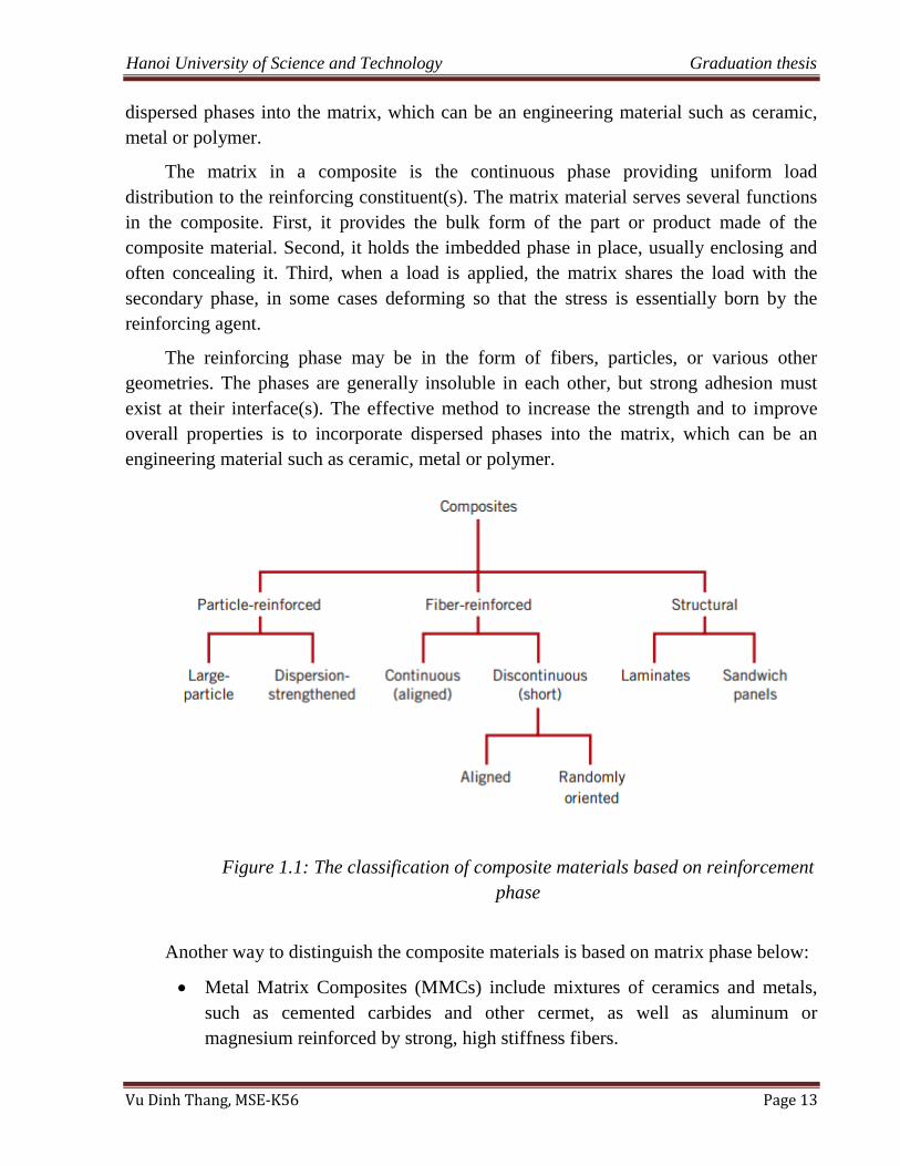
Figure 1.1: The classification of composite materials based on reinforcement
phase
Another way to distinguish the composite materials is based on matrix phase below:
Metal Matrix Composites (MMCs) include mixtures of ceramics and metals,
such as cemented carbides and other cermet, as well as aluminum or
magnesium reinforced by strong, high stiffness fibers.
Hanoi University of Science and Technology Graduation thesis
Vu Dinh Thang, MSE-K56 Page 14
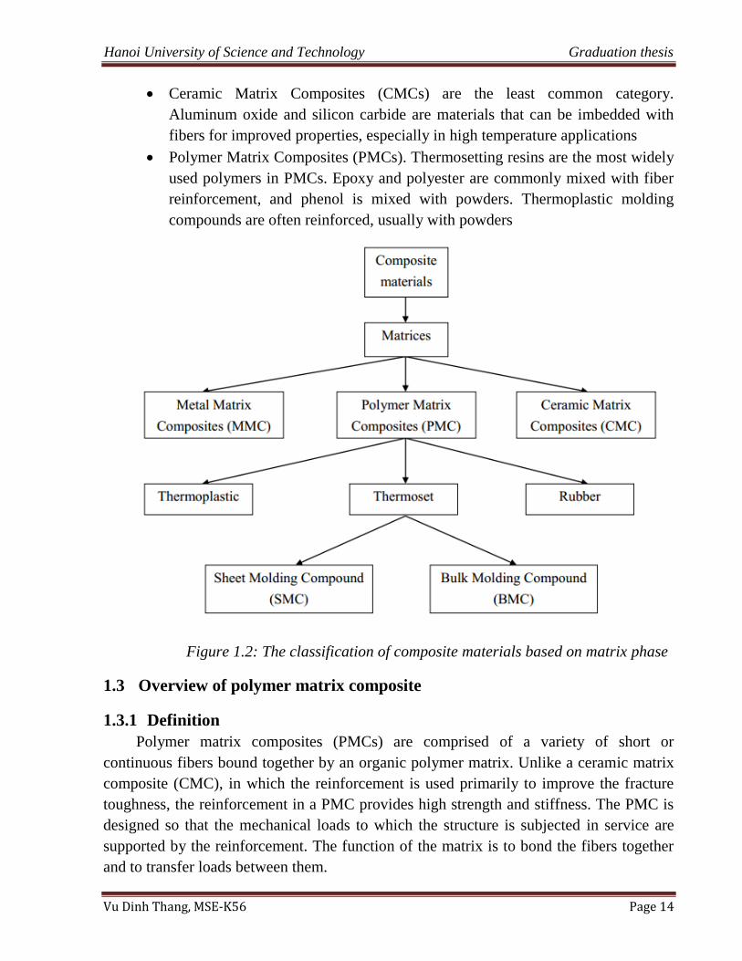
Ceramic Matrix Composites (CMCs) are the least common category.
Aluminum oxide and silicon carbide are materials that can be imbedded with
fibers for improved properties, especially in high temperature applications
Polymer Matrix Composites (PMCs). Thermosetting resins are the most widely
used polymers in PMCs. Epoxy and polyester are commonly mixed with fiber
reinforcement, and phenol is mixed with powders. Thermoplastic molding
compounds are often reinforced, usually with powders
Figure 1.2: The classification of composite materials based on matrix phase
1.3 Overview of polymer matrix composite
1.3.1 Definition
Polymer matrix composites (PMCs) are comprised of a variety of short or
continuous fibers bound together by an organic polymer matrix. Unlike a ceramic matrix
composite (CMC), in which the reinforcement is used primarily to improve the fracture
toughness, the reinforcement in a PMC provides high strength and stiffness. The PMC is
designed so that the mechanical loads to which the structure is subjected in service are
supported by the reinforcement. The function of the matrix is to bond the fibers together
and to transfer loads between them.
Hanoi University of Science and Technology Graduation thesis
Vu Dinh Thang, MSE-K56 Page 15
1.3.2 Properties
Polymer matrix composite is a class of composite materials, so it inherits many
advanced properties of composite materials. Besides, the advantages of PMCs are their
light weight coupled with high stiffness and strength along the direction of the
reinforcement. This combination is the basis of their usefulness in aircraft, automobiles,
and other moving structures. Other desirable properties include superior corrosion and
fatigue resistance compared to metals. Because the matrix decomposes at high
temperatures, however, current PMCs are limited to service temperatures below about
600° F (316° C).
1.3.3 Classification
A simple classification of polymer matrix composite is based on matrix phase, which
is given in Figure 1.2; the three classes: thermosets, thermoplastics and rubbers.
Thermosets: are composite whose resins react and harden either at room
temperature or on heating because the polymer of thermoset composite is
usually heavily cross-linked.
Thermoplastics: In thermoplastic composites, the individual molecules of
polymer are linear in structure with no chemical linking between them. They
are held in place by weak secondary bond such as van der Walls. Therefore,
these composites may be repeatedly heated, fabricated and cooled and
consequently scrap may be recycled.
Rubbers: the individual molecules of polymer are linear in structure, and there
is linking between them. They cannot be repeatedly heated or fabricated.
This study investigates the SMC composite materials which belong to thermosets
class.
1.4 Overview of SMC composite materials
1.4.1 Definition of SMC composite materials
Sheet molding compounds (SMC) are fiber-reinforced thermosetting semi-finished
products. They are produced in thin uncured and thickened sheets between 1 and 3 mm
thick that can be handled easily.
1.4.2 Matrix polymer of SMC composite materials
The matrix in a composite is the continuous phase providing uniform load
distribution to the reinforcing constituent(s). The matrix, in addition to protecting the
reinforcing constituent(s), safeguards the composite surface against abrasion, mechanical
damage and environmental corrosion.
Hanoi University of Science and Technology Graduation thesis
Vu Dinh Thang, MSE-K56 Page 16
In this research, the matrix of SMC composite material is made of unsaturated
polyester, catalysts and accelerators, fillers, thickeners and additives.
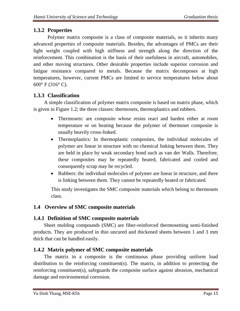
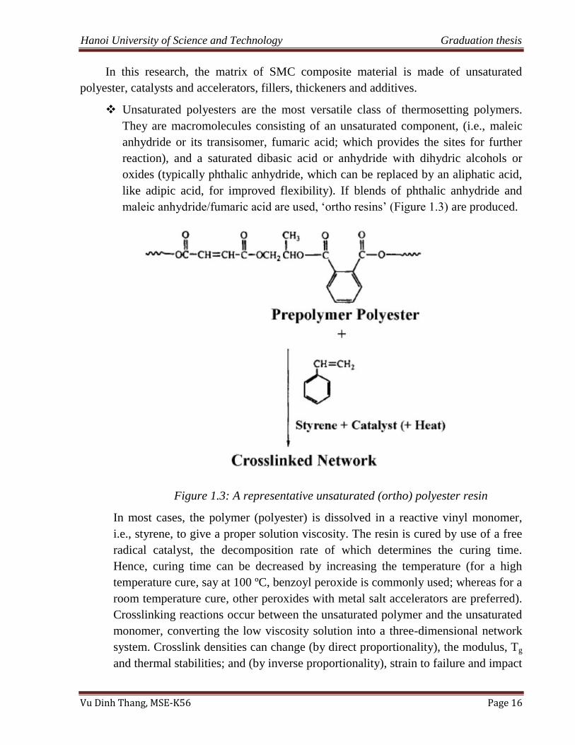
Unsaturated polyesters are the most versatile class of thermosetting polymers.
They are macromolecules consisting of an unsaturated component, (i.e., maleic
anhydride or its transisomer, fumaric acid; which provides the sites for further
reaction), and a saturated dibasic acid or anhydride with dihydric alcohols or
oxides (typically phthalic anhydride, which can be replaced by an aliphatic acid,
like adipic acid, for improved flexibility). If blends of phthalic anhydride and
maleic anhydride/fumaric acid are used, „ortho resins‟ (Figure 1.3) are produced.
Figure 1.3: A representative unsaturated (ortho) polyester resin
In most cases, the polymer (polyester) is dissolved in a reactive vinyl monomer,
i.e., styrene, to give a proper solution viscosity. The resin is cured by use of a free
radical catalyst, the decomposition rate of which determines the curing time.
Hence, curing time can be decreased by increasing the temperature (for a high
temperature cure, say at 100 ºC, benzoyl peroxide is commonly used; whereas for a
room temperature cure, other peroxides with metal salt accelerators are preferred).
Crosslinking reactions occur between the unsaturated polymer and the unsaturated
monomer, converting the low viscosity solution into a three-dimensional network
system. Crosslink densities can change (by direct proportionality), the modulus, Tg
and thermal stabilities; and (by inverse proportionality), strain to failure and impact
Hanoi University of Science and Technology Graduation thesis
Vu Dinh Thang, MSE-K56 Page 17
energies. The formation of the cross-link structure is accompanied by some volume
contraction (7%–27%).
Catalysts and accelerators: For polyester-type resins, peroxides are the main
catalysts. Common examples are benzoyl peroxide (BPO) and t-butyl perbenzoate,
which is a high temperature catalyst.
Fillers are used in SMC as low cost inert additives. In addition, fillers can:
o modify the viscosity and act as flow control agents
o reduce the CTE (coefficient of thermal expansion)
o serve as heat sink for exothermal that develop during the curing reaction
o increase hardness, rigidity and dimensional stability.
The most common powder filler is calcium carbonate. Ground clay (kaolin clay) is
also used; however it causes more discoloration and higher shrinkage than calcium
carbonate. Talc is often used for improved electrical strength and resistance to
humidity. Aluminum hydrate is commonly used for fire retardancy as it contains
35% of hydration water, which is released upon exposure to fire. Powdered
polyethylene is used in low profile (low shrinkage) formulations, since it improves
surface quality and impact strength. Antimony trioxide and chlorinated waxes are
also used for self-extinguishing properties.
Thickeners: To ensure controlled moldability, thickeners are used for controlled
increase of the viscosity of the polyester resin. Typical thickeners are magnesium
oxide and hydroxide, calcium oxides and hydroxides.
Miscellaneous additives: In addition to the additives mentioned in the previous
section, stearates are used for internal mold release and as various pigments for
coloring.
1.4.3 Reinforcement
Chopped E glass type fibbers are used as the reinforcing agent.
Glass fiber is simply a composite consisting of glass fibers, either continuous or
discontinuous, contained within a polymer matrix; this type of composite is produced in
the largest quantities. The composition of the glass that is most commonly drawn into
fibers (sometimes referred to as E-glass) is contained 55% wt of SiO2, 16% wt of CaO,
15% wt of Al2O3, 10% wt of B2O3, and 4% wt of MgO; fiber diameters normally range
between 3 and 20 µm.
Glass is an amorphous material composed of a silica network. There are four main
classes of glass used commercially: high alkali (essentially soda-lime-silica: A glass),
electrical grade (a calcium aluminous-borosilicate with low alkali oxide content: E glass),
chemically-resistant modified E glass grade (with calcium aluminous-silicate: ECR glass)
Hanoi University of Science and Technology Graduation thesis
Vu Dinh Thang, MSE-K56 Page 18
and high strength grade (with magnesium aluminous-silicate and no boron oxide: S glass).
Fibers from any of these can be prepared, however, E glass fiber is the one most widely
used for reinforcement purposes, although S glass fiber has the highest tensile strength
and elastic modulus of these four types of glasses (Table 1.1).
Glass fiber is spun from the melt and it is obtained after cooling it to the rigid
condition without crystallizing. Once the continuous glass fibers are produced, they are
transformed into one of the finished forms, which are (continuous or woven) roving,
yarns (mostly for textile applications), chopped strands, (glass fiber) mats and pre-forms.
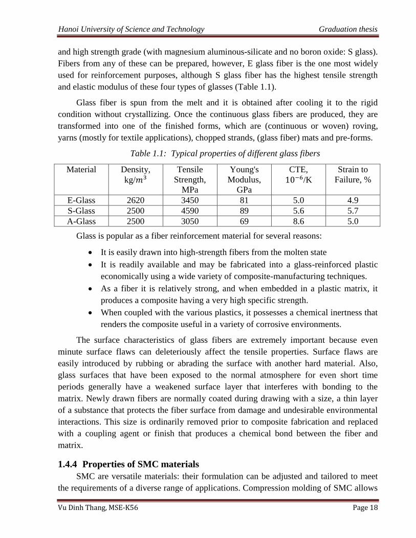
Table 1.1: Typical properties of different glass fibers
Material Density,
kg/
Tensile
Strength,
MPa
Young's
Modulus,
GPa
CTE,
/K
Strain to
Failure, %
E-Glass 2620 3450 81 5.0 4.9
S-Glass 2500 4590 89 5.6 5.7
A-Glass 2500 3050 69 8.6 5.0
Glass is popular as a fiber reinforcement material for several reasons:
It is easily drawn into high-strength fibers from the molten state
It is readily available and may be fabricated into a glass-reinforced plastic
economically using a wide variety of composite-manufacturing techniques.
As a fiber it is relatively strong, and when embedded in a plastic matrix, it
produces a composite having a very high specific strength.
When coupled with the various plastics, it possesses a chemical inertness that
renders the composite useful in a variety of corrosive environments.
The surface characteristics of glass fibers are extremely important because even
minute surface flaws can deleteriously affect the tensile properties. Surface flaws are
easily introduced by rubbing or abrading the surface with another hard material. Also,
glass surfaces that have been exposed to the normal atmosphere for even short time
periods generally have a weakened surface layer that interferes with bonding to the
matrix. Newly drawn fibers are normally coated during drawing with a size, a thin layer
of a substance that protects the fiber surface from damage and undesirable environmental
interactions. This size is ordinarily removed prior to composite fabrication and replaced
with a coupling agent or finish that produces a chemical bond between the fiber and
matrix.
1.4.4 Properties of SMC materials
SMC are versatile materials: their formulation can be adjusted and tailored to meet
the requirements of a diverse range of applications. Compression molding of SMC allows
Hanoi University of Science and Technology Graduation thesis
Vu Dinh Thang, MSE-K56 Page 19
processing complex and large shapes on a rapid cycle time. Features such as inserts, ribs,
bosses, and attachments can be molded in. This process needs little mold preparation and
generates few scraps, thus reducing the cost of trimming operations. Good surface
finishes are obtainable, contributing to lower part-finishing cost. This process can also be
automated.
Compared, for instance, to steels, SMC provide design freedom and flexibility by
accommodating shape complexity and geometric details; reduced manufacturing
complexity through part integration in a single assembly; and combining structural,
assembly, and integration functions (e.g., antennae embedment); substantial weight
reduction (∼20–35% lighter than equivalent steel parts); superior corrosion resistance;
and reduced tooling costs (40% less than tools for steel stamping). SMC also offer
enhanced damage resistance from dents and dings, especially in exterior cladding (body
panels), as compared to aluminum alloys and steels; good harshness properties; and good
noise and vibration properties. The benefits of using SMC are also: in-mold coloring and
powder priming for painted parts with the requirement of high temperature resistance
from 150 to 2000C for e-coat application.
Compared with injection molded parts, particularly those produced using the BMC
process; SMC parts have better mechanical properties. For instance, equivalent parts
exhibit typically an average thickness of 2.5 mm in the SMC case, whereas this thickness
is about 3.5 mm in the case of injection molded BMC to meet the same mechanical
requirements. This is due to the highest length of the fibers used in SMC. Even if fibers
having the same length can be used in both processes, it is known that injection processes
have a clear tendency to damage the fibrous reinforcement resulting in a drastic length
reduction. This shows a limitation and inefficiency in the injection processes. On the
contrary, compression molding allows a lower freedom of design and complex geometry
to be molded. This can be seen as an advantage when comparing SMC with prepreg
fabrics: the latter indeed offer higher mechanical properties, but the parts have simpler
geometry.
For many applications, SMC compete with fiber-reinforced thermoplastic materials.
Those materials can be injection molded or compression molded as GMT. SMC parts
have better mechanical properties, heat resistance, better than usual dimensional stability
and environmental resistance, and cost-effective thermoplastic composite parts. In
contrast, fiber-reinforced thermoplastics generate fewer scraps than SMC, thus lowering
labor costs. Furthermore, SMC have some disadvantages: the continuous thickening of
the paste, the variations of the rheological properties, as well as the emission of styrene,
which impacts the curing reaction, the variations of the basis weight, and the cooling of
molding parts, which may induce some geometrical distortions if not controlled properly,
Hanoi University of Science and Technology Graduation thesis
Vu Dinh Thang, MSE-K56 Page 20
still remain tricky to control at the industrial scale. But there is no clear trend yet that
SMC will be replaced by composite thermoplastics. Indeed, assembly can be
manufactured from a subset of parts. SMC can be used for the structural parts of the
assembly, whereas visible skins can be composed of thermoplastic composites. This type
of solution is currently implemented in the automotive industry. Nevertheless, painted
SMC body panels are still being produced without major insoluble industrial problems.
Various formulations yield a spectrum of physical and mechanical properties of the
final products.
Table 1.2: Typical properties of SMC
General Purpose High Toughness Low Shrink
Specific gravity 1.14 1.17 1.67
Flex modulus, GPa 4.2 3.9 11.6
Flex strength, MPa 95 150 85
Tensile strength, MPa 70 76 35
Tensile elongation, % 1.8 4.0 -
Barcol hardness 50 45 60
1.5 Fabricating SMC materials
According to a research about sheet molding composite on Dat‟s graduation thesis
[10] and a paper of LAURENT ORGEAS [4], the fabricating process of SMC material is
showed below.
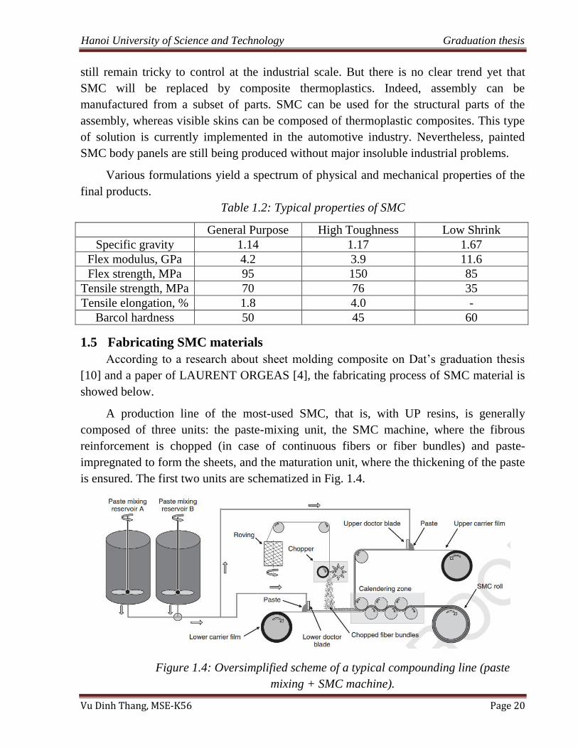
A production line of the most-used SMC, that is, with UP resins, is generally
composed of three units: the paste-mixing unit, the SMC machine, where the fibrous
reinforcement is chopped (in case of continuous fibers or fiber bundles) and paste-
impregnated to form the sheets, and the maturation unit, where the thickening of the paste
is ensured. The first two units are schematized in Fig. 1.4.
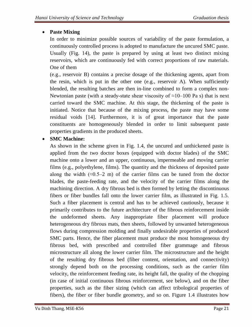
Figure 1.4: Oversimplified scheme of a typical compounding line (paste
mixing + SMC machine).
Hanoi University of Science and Technology Graduation thesis
Vu Dinh Thang, MSE-K56 Page 21
Paste Mixing
In order to minimize possible sources of variability of the paste formulation, a
continuously controlled process is adopted to manufacture the uncured SMC paste.
Usually (Fig. 14), the paste is prepared by using at least two distinct mixing
reservoirs, which are continuously fed with correct proportions of raw materials.
One of them
(e.g., reservoir B) contains a precise dosage of the thickening agents, apart from
the resin, which is put in the other one (e.g., reservoir A). When sufficiently
blended, the resulting batches are then in-line combined to form a complex non-
Newtonian paste (with a steady-state shear viscosity of ≈10–100 Pa s) that is next
carried toward the SMC machine. At this stage, the thickening of the paste is
initiated. Notice that because of the mixing process, the paste may have some
residual voids [14]. Furthermore, it is of great importance that the paste
constituents are homogeneously blended in order to limit subsequent paste
properties gradients in the produced sheets.
SMC Machine:
As shown in the scheme given in Fig. 1.4, the uncured and unthickened paste is
applied from the two doctor boxes (equipped with doctor blades) of the SMC
machine onto a lower and an upper, continuous, impermeable and moving carrier
films (e.g., polyethylene, films). The quantity and the thickness of deposited paste
along the width (≈0.5–2 m) of the carrier films can be tuned from the doctor
blades, the paste-feeding rate, and the velocity of the carrier films along the
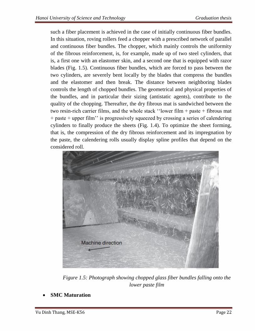
machining direction. A dry fibrous bed is then formed by letting the discontinuous
fibers or fiber bundles fall onto the lower carrier film, as illustrated in Fig. 1.5.
Such a fiber placement is central and has to be achieved cautiously, because it
primarily contributes to the future architecture of the fibrous reinforcement inside
the undeformed sheets. Any inappropriate fiber placement will produce
heterogeneous dry fibrous mats, then sheets, followed by unwanted heterogeneous
flows during compression molding and finally undesirable properties of produced
SMC parts. Hence, the fiber placement must produce the most homogeneous dry
fibrous bed, with prescribed and controlled fiber grammage and fibrous
microstructure all along the lower carrier film. The microstructure and the height
of the resulting dry fibrous bed (fiber content, orientation, and connectivity)
strongly depend both on the processing conditions, such as the carrier film
velocity, the reinforcement feeding rate, its height fall, the quality of the chopping
(in case of initial continuous fibrous reinforcement, see below), and on the fiber
properties, such as the fiber sizing (which can affect tribological properties of
fibers), the fiber or fiber bundle geometry, and so on. Figure 1.4 illustrates how
Hanoi University of Science and Technology Graduation thesis
Vu Dinh Thang, MSE-K56 Page 22
such a fiber placement is achieved in the case of initially continuous fiber bundles.
In this situation, roving rollers feed a chopper with a prescribed network of parallel
and continuous fiber bundles. The chopper, which mainly controls the uniformity
of the fibrous reinforcement, is, for example, made up of two steel cylinders, that
is, a first one with an elastomer skin, and a second one that is equipped with razor
blades (Fig. 1.5). Continuous fiber bundles, which are forced to pass between the
two cylinders, are severely bent locally by the blades that compress the bundles
and the elastomer and then break. The distance between neighboring blades
controls the length of chopped bundles. The geometrical and physical properties of
the bundles, and in particular their sizing (antistatic agents), contribute to the
quality of the chopping. Thereafter, the dry fibrous mat is sandwiched between the
two resin-rich carrier films, and the whole stack „„lower film + paste + fibrous mat
+ paste + upper film‟‟ is progressively squeezed by crossing a series of calendering
cylinders to finally produce the sheets (Fig. 1.4). To optimize the sheet forming,
that is, the compression of the dry fibrous reinforcement and its impregnation by
the paste, the calendering rolls usually display spline profiles that depend on the
considered roll.
Figure 1.5: Photograph showing chopped glass fiber bundles falling onto the
lower paste film
SMC Maturation
Hanoi University of Science and Technology Graduation thesis
Vu Dinh Thang, MSE-K56 Page 23
After the SMC machine, the produced and collected sheets are often packed by a
thin polymer film (e.g., cellophane). This film limits the loss of styrene before the
end of thickening and compression molding, whereas the PE carrier films also
protect the produced sheets from humidity. These two types of protection films,
together with the strict preconditioning of the raw materials guarantee, in case of
metal oxides or hydroxides thickening agents, the best maturation conditions and
conservation of thickened SMC. Furthermore, to ensure optimal thickening,
packed sheets are stored in a dedicated maturation area, where the temperature
(nominal value ranging between 20 and 30C) together with the relative humidity
(nominal value ranging between 20% and 50% HR) are accurately controlled.
Under such maturation conditions, the thickening of the paste is properly achieved
until the paste viscosity reaches a forming plateau (cf. Fig. 7). Beyond this
maturation time, the SMC can be preserved (in colder rooms) and used for
compression molding for several weeks or months (depending on the paste
formulation)
1.6 Applications of SMC materials
Today, SMC materials are used worldwide and represent a major part of the world‟s
thermoset composites. Globally, the compression molding of SMC is the third most
intensively used technique for the production of polymer composite parts worldwide
(behind the injection of reinforced thermoplastics and the hand lay-up techniques). It
represents about 15% of the total of produced parts and of the total of materials used by
the composite industry. There is a large diversity of fields of applications for SMC. The
automotive and truck industries remain the drivers of the SMC technology, but SMC are
commonly used in the agricultural, rail and marine (interior and body parts, watercraft
parts, etc.), electrical (low voltage and medium voltage energy systems, fuses and
switchgear, cabinets and junction boxes, encapsulation of wirings and electronic circuits,
electrical components with reduced surface resistivity, lamp housings) and energy (parts
for wind turbine and solar power applications, etc.), sanitary (sinks and bath tubs, toilet
seats, drain covers, etc.), domestic appliance (blower housings, drain pans, and heating,
ventilation, and air conditioning (HVAC) systems, vent trims, parabolic mirrors,
swimming pool panels, etc.), building and construction (drinking water tanks, panels,
doors, etc.), and medical (surgery equipment, dental medication systems, antibacterial
components) sectors.
In the automotive and truck industries, SMC parts are used notably in exterior and
interior body panels, painted (class A parts) and unpainted, semi-structural and structural
parts. Basically, class A means that the surface finish has to exhibit an aspect of flatness,
smoothness, and light reflection similar to that of stamped steels. A non-exhaustive list of
Hanoi University of Science and Technology Graduation thesis
Vu Dinh Thang, MSE-K56 Page 24
automotive parts gives, for instance, bumpers, fenders, trunk divider, hood and door
assemblies, deck lids, body panels, fenders, roof panels, spoilers, step assists, back panels,
wheelhouses, firewalls, grilles, tailboards, cargo lids, stowage tubs, headlamp housings,
and supports. More recently, high temperature under-hood parts have been developed
(e.g., valve covers).
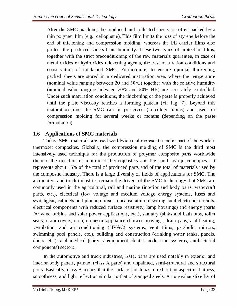
SMC composite materials are widely used to produce assemble parts in short time
curing. Typical applications include demanding electrical applications, corrosion resistant
needs, structural components at low cost, automotive, and transit. SMC delivers high
surface quality. SMC is used for larger parts where higher mechanical strength is needed.
Figure 1.6: Applications of SMC composite materials
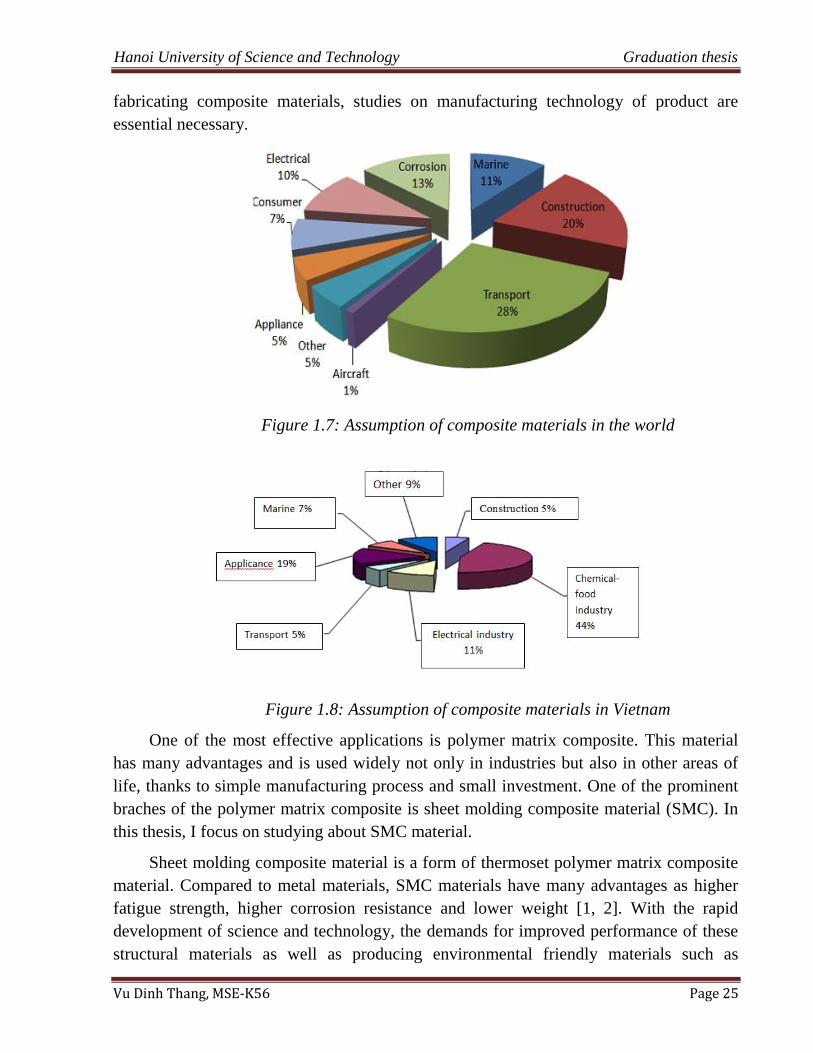
1.7 History and current research about SMC materials
In the today industrialized trend of my country, the composite products are used
more and more widely, at the same time the quality requirements for these products are
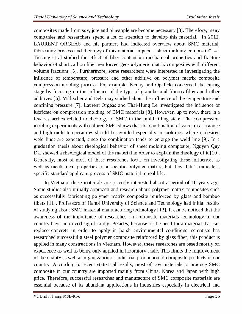
also enhanced. The below pie charts shows that consumption and applicant fields of
composite materials in the word and in Vietnam (Figure 1.7, 1.8). This requires that
people must seize control of modern technology, of which the two main requirements are
high productivity and stable quality. Therefore, being along with researches about
Hanoi University of Science and Technology Graduation thesis
Vu Dinh Thang, MSE-K56 Page 25
fabricating composite materials, studies on manufacturing technology of product are
essential necessary.
Figure 1.7: Assumption of composite materials in the world
Figure 1.8: Assumption of composite materials in Vietnam
One of the most effective applications is polymer matrix composite. This material
has many advantages and is used widely not only in industries but also in other areas of
life, thanks to simple manufacturing process and small investment. One of the prominent
braches of the polymer matrix composite is sheet molding composite material (SMC). In
this thesis, I focus on studying about SMC material.
Sheet molding composite material is a form of thermoset polymer matrix composite
material. Compared to metal materials, SMC materials have many advantages as higher
fatigue strength, higher corrosion resistance and lower weight [1, 2]. With the rapid
development of science and technology, the demands for improved performance of these
structural materials as well as producing environmental friendly materials such as
Hanoi University of Science and Technology Graduation thesis
Vu Dinh Thang, MSE-K56 Page 26
composites made from soy, jute and pineapple are become necessary [3]. Therefore, many
companies and researchers spend a lot of attention to develop this material. In 2012,
LAURENT ORGEAS and his partners had indicated overview about SMC material,
fabricating process and rheology of this material in paper “sheet molding composite” [4].
Tiesong et al studied the effect of fiber content on mechanical properties and fracture
behavior of short carbon fiber reinforced geo-polymeric matrix composites with different
volume fractions [5]. Furthermore, some researchers were interested in investigating the
influence of temperature, pressure and other additive on polymer matrix composite
compression molding process. For example, Kenny and Opalicki concerned the curing
stage by focusing on the influence of the type of granular and fibrous fillers and other
additives [6]. Millischer and Delaunay studied about the influence of the temperature and
confining pressure [7]. Laurent Orgéas and Thai-Hung Le investigated the influence of
lubricate on compression molding of BMC materials [8]. However, up to now, there is a
few researches related to rheology of SMC in the mold filling state. The compression
molding experiments with colored SMC shows that the combination of vacuum assistance
and high mold temperatures should be avoided especially in moldings where undesired
weld lines are expected, since the combination tends to enlarge the weld line [9]. In a
graduation thesis about rheological behavior of sheet molding composite, Nguyen Quy
Dat showed a rheological model of the material in order to explain the rheology of it [10].
Generally, most of most of these researches focus on investigating these influences as
well as mechanical properties of a specific polymer matrix, but they didn‟t indicate a
specific standard applicant process of SMC material in real life.
In Vietnam, these materials are recently interested about a period of 10 years ago.
Some studies also initially approach and research about polymer matrix composites such
as successfully fabricating polymer matrix composite reinforced by glass and bamboo
fibers [11]. Professors of Hanoi University of Science and Technology had initial results
of studying about SMC material manufacturing technology [12]. It can be noticed that the
awareness of the importance of researches on composite materials technology in our
country have improved significantly. Besides, because of the need for a material that can
replace concrete in order to apply in harsh environmental conditions, scientists has
researched successful a steel polymer composite reinforced by glass fiber; this product is
applied in many constructions in Vietnam. However, these researches are based mostly on
experience as well as being only applied in laboratory scale. This limits the improvement
of the quality as well as organization of industrial production of composite products in our
country. According to recent statistical results, most of raw materials to produce SMC
composite in our country are imported mainly from China, Korea and Japan with high
price. Therefore, successful researches and manufacture of SMC composite materials are
essential because of its abundant applications in industries especially in electrical and
Hanoi University of Science and Technology Graduation thesis
Vu Dinh Thang, MSE-K56 Page 27
automotive industry. Furthermore, researches on the electrical field of manufacturing
polymer matrix composite materials are now mainly focus to fabricate with phenolic
resin. The main disadvantage of this polymer is the longer time of compression process as
well as higher temperature than SMC materials. Also, electrical parts are manufactured by
thermoplastic materials with low cost, but its thermal resistant ability is so low. Moreover,
working life of this material is rapidly declined in outdoor environments. Besides, in
previous research, we have successfully fabricated circuit breaker products by using bulk
molding composite materials [15]. This research will focus on using simulation software
in order to test accuracy of the electrical cover mold as well as indicating a standard
process to manufacture socket cover product.
1.8 Summary
Through this chapter, we can see that SMC materials are used widely in electrical
and automotive industries thanks to its advanced properties such as light, high corrosion.
However, while most of domestic researches are only focused on fabricating SMC
materials and properties of SMC, there are a few researches studying on standard
procedure to apply SMC materials in electrical industry. Therefore, this thesis researches
on using SMC material to manufacture electrical socket cover and investigates
mechanical, thermal and electrical properties of the product.
Hanoi University of Science and Technology Graduation thesis
Vu Dinh Thang, MSE-K56 Page 28
CHAPTER 2
2 DESIGNING THE MOLD AND SIMULATING
COMPRESSION PROCESS
2.1 Overview about compression molding
Compression molding is a molding method in which the molding material, generally
preheated, is first placed in an open, heated mold cavity. The mold is closed with a top
force or plug member, pressure is applied to force the material into contact with all mold
areas, while heat and pressure are maintained until the molding material has cured. The
process employs thermosetting resins in a partially cured stage, either in the form of
granules, putty-like masses, or preforms.
Materials may be loaded into the mold either in the form of pellets or sheet, or the
mold may be loaded from a plasticizing extruder. Materials are heated above their melting
points, formed and cooled. The more evenly the feed material is distributed over the mold
surface, the less flow orientation occurs during the compression stage.
Compression molding is a high-volume, high-pressure method suitable for molding
complex, high-strength glass fiber reinforcements. Advanced composite thermoplastics
can also be compression molded with unidirectional tapes, woven fabrics, randomly
oriented fiber mat or chopped strand. The advantage of compression molding is its ability
to mold large, fairly intricate parts. Also, it is one of the lowest cost molding methods
compared with other methods such as transfer molding and injection molding; moreover it
wastes relatively little material, giving it an advantage when working with expensive
compounds.
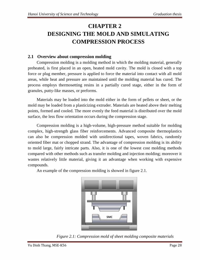
An example of the compression molding is showed in figure 2.1.
Figure 2.1: Compression mold of sheet molding composite materials
Hanoi University of Science and Technology Graduation thesis
Vu Dinh Thang, MSE-K56 Page 29
In order to product electrical socket cover, a compression mold is applied in this
research.
2.2 Technical demands of a compression mold
Parts or products, which are manufactured by compression molding method, is
demanded to have correct size as well as satisfy technical requirements of product
drawing.
The mold should be designed to manipulate easily.
The working and exposure surfaces of the mold must ensure the glossy and
smoothness in order to decrease the friction and the adhesion of SMC materials
onto the mold.
Components of the mold should be undergone heat treatment so that ensure
toughness of the mold. Besides, we should choose appropriate material for each
component of the mold.
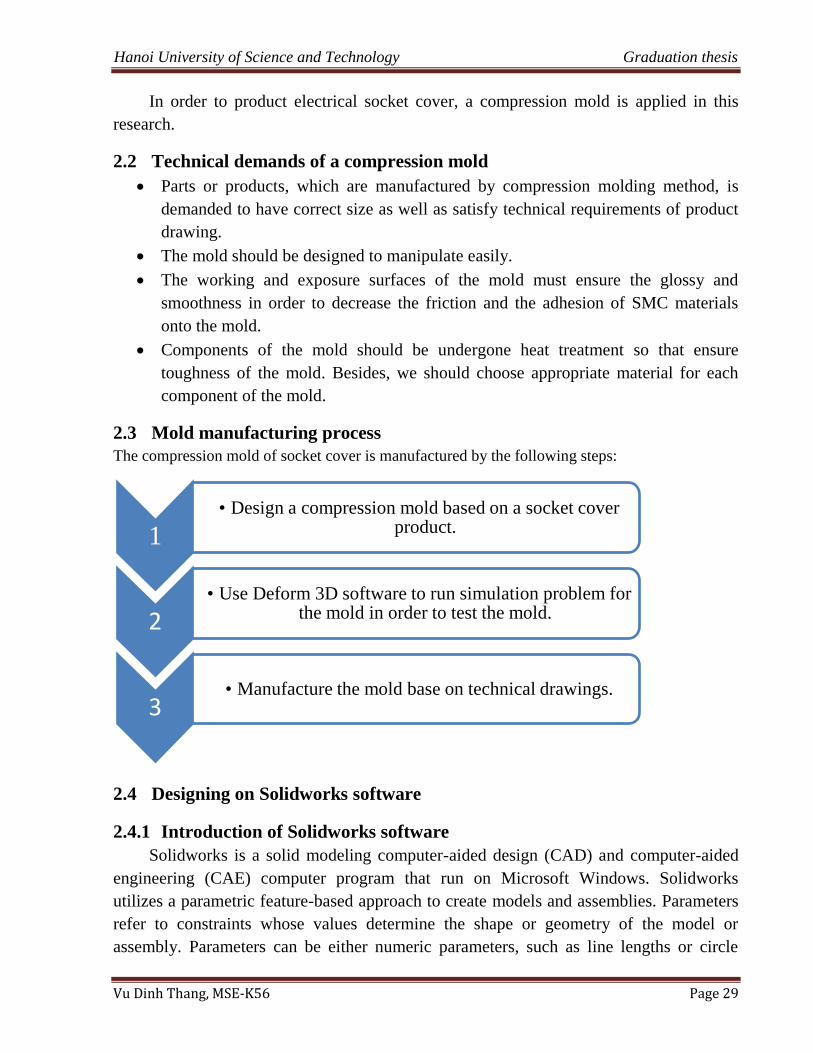
2.3 Mold manufacturing process
The compression mold of socket cover is manufactured by the following steps:
2.4 Designing on Solidworks software
2.4.1 Introduction of Solidworks software
Solidworks is a solid modeling computer-aided design (CAD) and computer-aided
engineering (CAE) computer program that run on Microsoft Windows. Solidworks
utilizes a parametric feature-based approach to create models and assemblies. Parameters
refer to constraints whose values determine the shape or geometry of the model or
assembly. Parameters can be either numeric parameters, such as line lengths or circle
1
• Design a compression mold based on a socket cover product.
2 • Use Deform 3D software to run simulation problem for
the mold in order to test the mold.
3 • Manufacture the mold base on technical drawings.
Hanoi University of Science and Technology Graduation thesis
Vu Dinh Thang, MSE-K56 Page 30
diameters, or geometric parameters, such as tangent, parallel, concentric, horizontal or
vertical, etc. Design intent is how the creator of the part wants it to respond to changes
and updates. Features refer to the building blocks of the part. They are the shapes and
operations that construct the part.
Solidworks software is applied broadly in mechanical design, construction and
architecture… in order to create details or products with complex shape and surface that
the other software cannot design. Therefore, Solidworks is the most suitable software to
design and manufacture a compression mold.
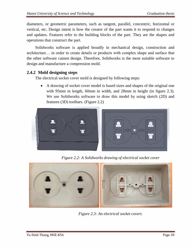
2.4.2 Mold designing steps
The electrical socket cover mold is designed by following steps:
A drawing of socket cover model is based sizes and shapes of the original one
with 95mm in length, 60mm in width, and 28mm in height (in figure 2.3).
We use Solidworks software to draw this model by using sketch (2D) and
features (3D) toolbars. (Figure 2.2)
Figure 2.2: A Solidworks drawing of electrical socket cover
Figure 2.3: An electrical socket covert.
Hanoi University of Science and Technology Graduation thesis
Vu Dinh Thang, MSE-K56 Page 31
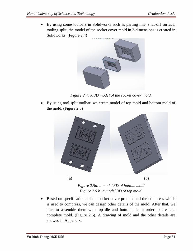
By using some toolbars in Solidworks such as parting line, shut-off surface,
tooling split, the model of the socket cover mold in 3-dimensions is created in
Solidworks. (Figure 2.4)
Figure 2.4: A 3D model of the socket cover mold.
By using tool split toolbar, we create model of top mold and bottom mold of
the mold. (Figure 2.5)
(a) (b)
Figure 2.5a: a model 3D of bottom mold
Figure 2.5 b: a model 3D of top mold.
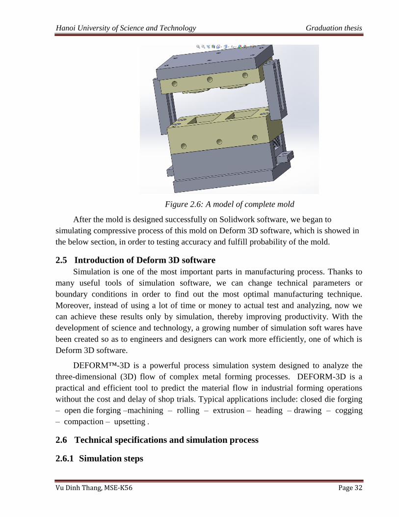
Based on specifications of the socket cover product and the compress which
is used to compress, we can design other details of the mold. After that, we
start to assemble them with top die and bottom die in order to create a
complete mold. (Figure 2.6). A drawing of mold and the other details are
showed in Appendix.
Hanoi University of Science and Technology Graduation thesis
Vu Dinh Thang, MSE-K56 Page 32
Figure 2.6: A model of complete mold
After the mold is designed successfully on Solidwork software, we began to
simulating compressive process of this mold on Deform 3D software, which is showed in
the below section, in order to testing accuracy and fulfill probability of the mold.
2.5 Introduction of Deform 3D software
Simulation is one of the most important parts in manufacturing process. Thanks to
many useful tools of simulation software, we can change technical parameters or
boundary conditions in order to find out the most optimal manufacturing technique.
Moreover, instead of using a lot of time or money to actual test and analyzing, now we
can achieve these results only by simulation, thereby improving productivity. With the
development of science and technology, a growing number of simulation soft wares have
been created so as to engineers and designers can work more efficiently, one of which is
Deform 3D software.
DEFORM™-3D is a powerful process simulation system designed to analyze the
three-dimensional (3D) flow of complex metal forming processes. DEFORM-3D is a
practical and efficient tool to predict the material flow in industrial forming operations
without the cost and delay of shop trials. Typical applications include: closed die forging
– open die forging –machining – rolling – extrusion – heading – drawing – cogging
– compaction – upsetting .
2.6 Technical specifications and simulation process
2.6.1 Simulation steps
Hanoi University of Science and Technology Graduation thesis
Vu Dinh Thang, MSE-K56 Page 33
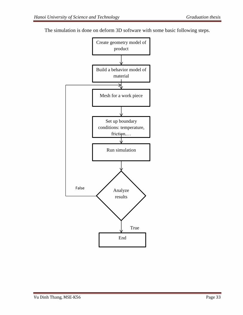
The simulation is done on deform 3D software with some basic following steps.
Create geometry model of
product
Build a behavior model of
material
Mesh for a work piece
Set up boundary
conditions: temperature,
friction,…
Run simulation
Analyze
results
True
End
False
Hanoi University of Science and Technology Graduation thesis
Vu Dinh Thang, MSE-K56 Page 34
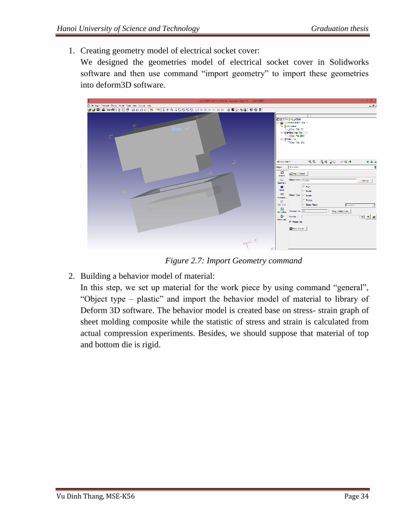
1. Creating geometry model of electrical socket cover:
We designed the geometries model of electrical socket cover in Solidworks
software and then use command “import geometry” to import these geometries
into deform3D software.
Figure 2.7: Import Geometry command
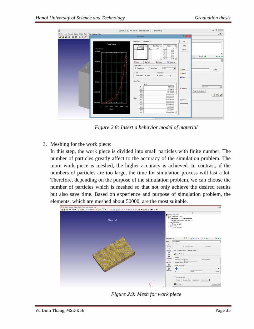
2. Building a behavior model of material:
In this step, we set up material for the work piece by using command “general”,
“Object type – plastic” and import the behavior model of material to library of
Deform 3D software. The behavior model is created base on stress- strain graph of
sheet molding composite while the statistic of stress and strain is calculated from
actual compression experiments. Besides, we should suppose that material of top
and bottom die is rigid.
Hanoi University of Science and Technology Graduation thesis
Vu Dinh Thang, MSE-K56 Page 35
Figure 2.8: Insert a behavior model of material
3. Meshing for the work piece:
In this step, the work piece is divided into small particles with finite number. The
number of particles greatly affect to the accuracy of the simulation problem. The
more work piece is meshed, the higher accuracy is achieved. In contrast, if the
numbers of particles are too large, the time for simulation process will last a lot.
Therefore, depending on the purpose of the simulation problem, we can choose the
number of particles which is meshed so that not only achieve the desired results
but also save time. Based on experience and purpose of simulation problem, the
elements, which are meshed about 50000, are the most suitable.
Figure 2.9: Mesh for work piece
Hanoi University of Science and Technology Graduation thesis
Vu Dinh Thang, MSE-K56 Page 36
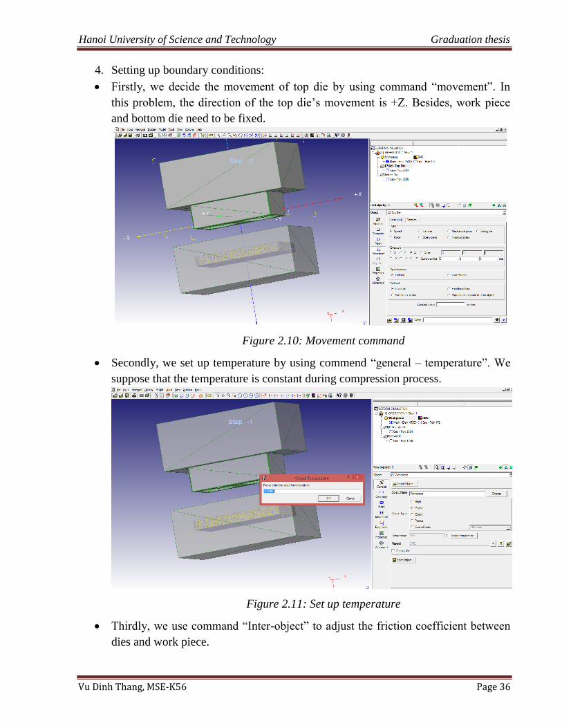
4. Setting up boundary conditions:
Firstly, we decide the movement of top die by using command “movement”. In
this problem, the direction of the top die‟s movement is +Z. Besides, work piece
and bottom die need to be fixed.
Figure 2.10: Movement command
Secondly, we set up temperature by using commend “general – temperature”. We
suppose that the temperature is constant during compression process.
Figure 2.11: Set up temperature
Thirdly, we use command “Inter-object” to adjust the friction coefficient between
dies and work piece.
Hanoi University of Science and Technology Graduation thesis
Vu Dinh Thang, MSE-K56 Page 37
Figure 2.12: Set up friction coefficient
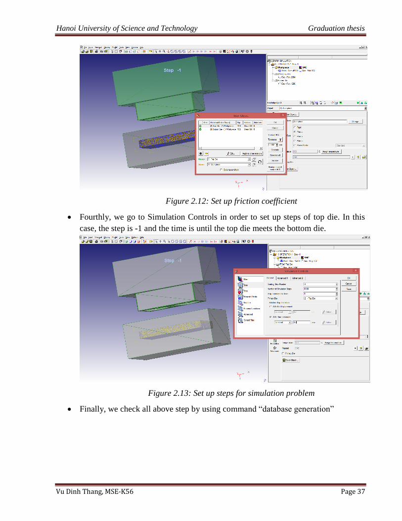
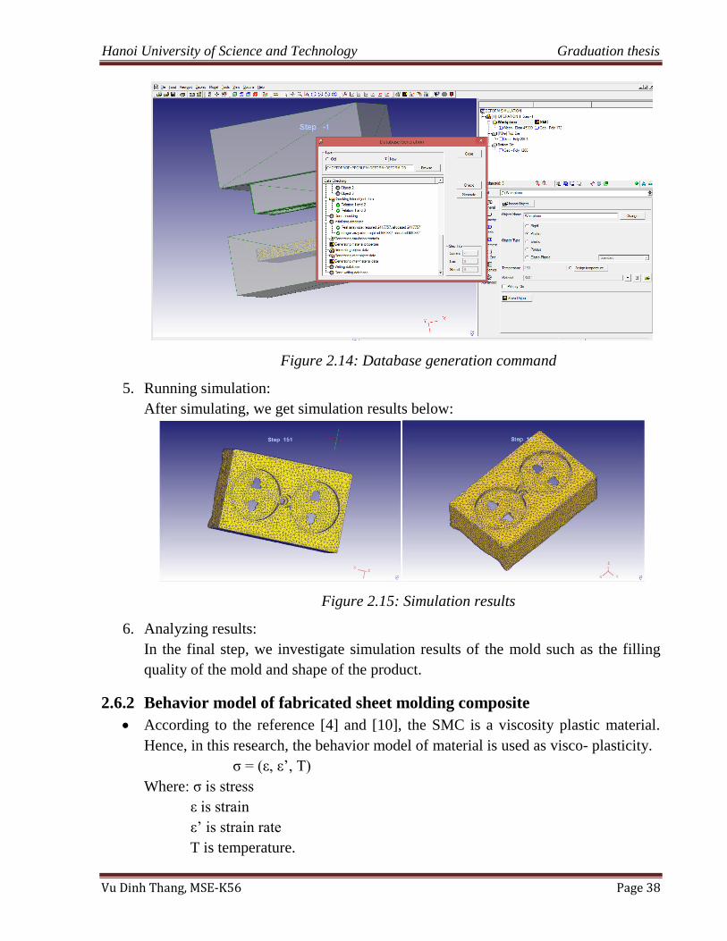
Fourthly, we go to Simulation Controls in order to set up steps of top die. In this
case, the step is -1 and the time is until the top die meets the bottom die.
Figure 2.13: Set up steps for simulation problem
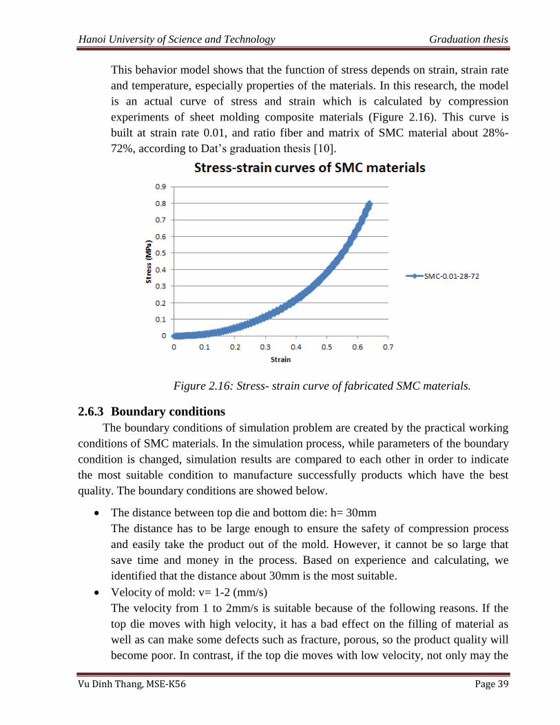
Finally, we check all above step by using command “database generation”
Hanoi University of Science and Technology Graduation thesis
Vu Dinh Thang, MSE-K56 Page 38
Figure 2.14: Database generation command
5. Running simulation:
After simulating, we get simulation results below:
Figure 2.15: Simulation results
6. Analyzing results:
In the final step, we investigate simulation results of the mold such as the filling
quality of the mold and shape of the product.
2.6.2 Behavior model of fabricated sheet molding composite
According to the reference [4] and [10], the SMC is a viscosity plastic material.
Hence, in this research, the behavior model of material is used as visco- plasticity.
σ = (ε, ε‟, T)
Where: σ is stress
ε is strain
ε‟ is strain rate
T is temperature.
Hanoi University of Science and Technology Graduation thesis
Vu Dinh Thang, MSE-K56 Page 39
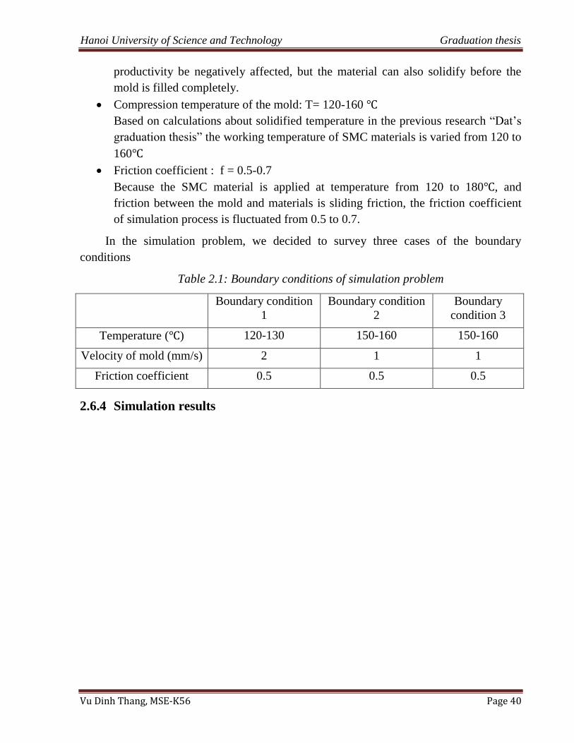
This behavior model shows that the function of stress depends on strain, strain rate
and temperature, especially properties of the materials. In this research, the model
is an actual curve of stress and strain which is calculated by compression
experiments of sheet molding composite materials (Figure 2.16). This curve is
built at strain rate 0.01, and ratio fiber and matrix of SMC material about 28%-
72%, according to Dat‟s graduation thesis [10].
Figure 2.16: Stress- strain curve of fabricated SMC materials.
2.6.3 Boundary conditions
The boundary conditions of simulation problem are created by the practical working
conditions of SMC materials. In the simulation process, while parameters of the boundary
condition is changed, simulation results are compared to each other in order to indicate
the most suitable condition to manufacture successfully products which have the best
quality. The boundary conditions are showed below.
The distance between top die and bottom die: h= 30mm
The distance has to be large enough to ensure the safety of compression process
and easily take the product out of the mold. However, it cannot be so large that
save time and money in the process. Based on experience and calculating, we
identified that the distance about 30mm is the most suitable.
Velocity of mold: v= 1-2 (mm/s)
The velocity from 1 to 2mm/s is suitable because of the following reasons. If the
top die moves with high velocity, it has a bad effect on the filling of material as
well as can make some defects such as fracture, porous, so the product quality will
become poor. In contrast, if the top die moves with low velocity, not only may the
Hanoi University of Science and Technology Graduation thesis
Vu Dinh Thang, MSE-K56 Page 40
productivity be negatively affected, but the material can also solidify before the
mold is filled completely.
Compression temperature of the mold: T= 120-160
Based on calculations about solidified temperature in the previous research “Dat‟s
graduation thesis” the working temperature of SMC materials is varied from 120 to
160
Friction coefficient : f = 0.5-0.7
Because the SMC material is applied at temperature from 120 to 180 , and
friction between the mold and materials is sliding friction, the friction coefficient
of simulation process is fluctuated from 0.5 to 0.7.
In the simulation problem, we decided to survey three cases of the boundary
conditions
Table 2.1: Boundary conditions of simulation problem
Boundary condition
1
Boundary condition
2
Boundary
condition 3
Temperature ( ) 120-130 150-160 150-160
Velocity of mold (mm/s) 2 1 1
Friction coefficient 0.5 0.5 0.5
2.6.4 Simulation results
Hanoi University of Science and Technology Graduation thesis
Vu Dinh Thang, MSE-K56 Page 41
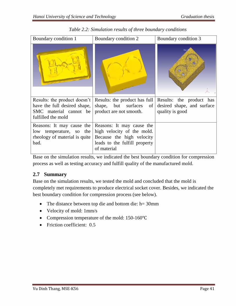
Table 2.2: Simulation results of three boundary conditions
Boundary condition 1 Boundary condition 2 Boundary condition 3
Results: the product doesn‟t
have the full desired shape,
SMC material cannot be
fulfilled the mold
Results: the product has full
shape, but surfaces of
product are not smooth.
Results: the product has
desired shape, and surface
quality is good
Reasons: It may cause the
low temperature, so the
rheology of material is quite
bad.
Reasons: It may cause the
high velocity of the mold.
Because the high velocity
leads to the fulfill property
of material
Base on the simulation results, we indicated the best boundary condition for compression
process as well as testing accuracy and fulfill quality of the manufactured mold.
2.7 Summary
Base on the simulation results, we tested the mold and concluded that the mold is
completely met requirements to produce electrical socket cover. Besides, we indicated the
best boundary condition for compression process (see below).
The distance between top die and bottom die: h= 30mm
Velocity of mold: 1mm/s
Compression temperature of the mold: 150-160
Friction coefficient: 0.5
Hanoi University of Science and Technology Graduation thesis
Vu Dinh Thang, MSE-K56 Page 42
3 CHAPTER 3
FABRICATING ELECTRICAL SOCKET COVER
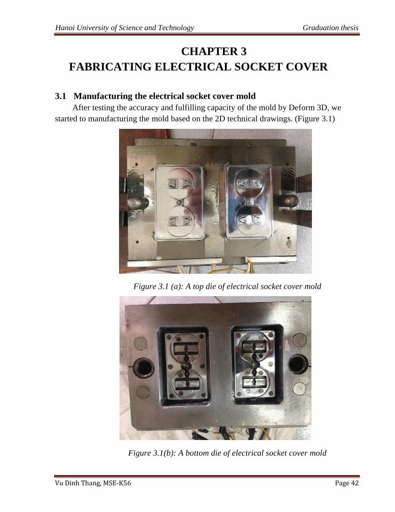
3.1 Manufacturing the electrical socket cover mold
After testing the accuracy and fulfilling capacity of the mold by Deform 3D, we
started to manufacturing the mold based on the 2D technical drawings. (Figure 3.1)
Figure 3.1 (a): A top die of electrical socket cover mold
Figure 3.1(b): A bottom die of electrical socket cover mold
Hanoi University of Science and Technology Graduation thesis
Vu Dinh Thang, MSE-K56 Page 43
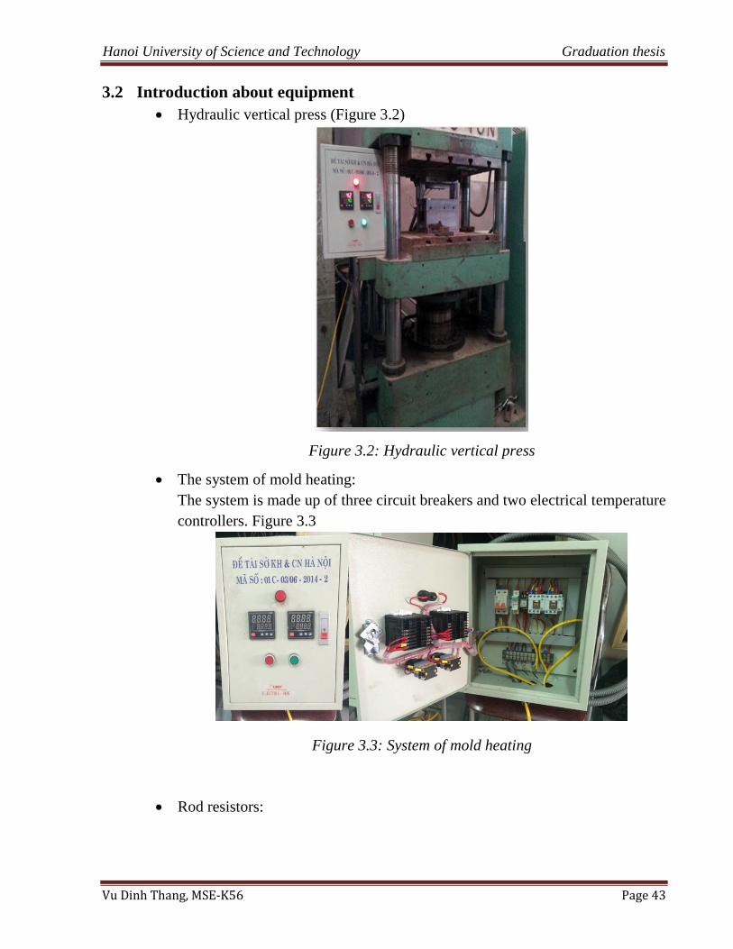
3.2 Introduction about equipment
Hydraulic vertical press (Figure 3.2)
Figure 3.2: Hydraulic vertical press
The system of mold heating:
The system is made up of three circuit breakers and two electrical temperature
controllers. Figure 3.3
Figure 3.3: System of mold heating
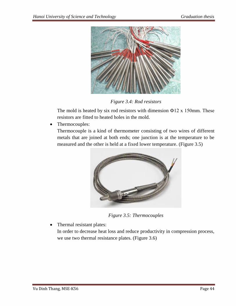
Rod resistors:
Hanoi University of Science and Technology Graduation thesis
Vu Dinh Thang, MSE-K56 Page 44
Figure 3.4: Rod resistors
The mold is heated by six rod resistors with dimension Ф12 x 150mm. These
resistors are fitted to heated holes in the mold.
Thermocouples:
Thermocouple is a kind of thermometer consisting of two wires of different
metals that are joined at both ends; one junction is at the temperature to be
measured and the other is held at a fixed lower temperature. (Figure 3.5)
Figure 3.5: Thermocouples
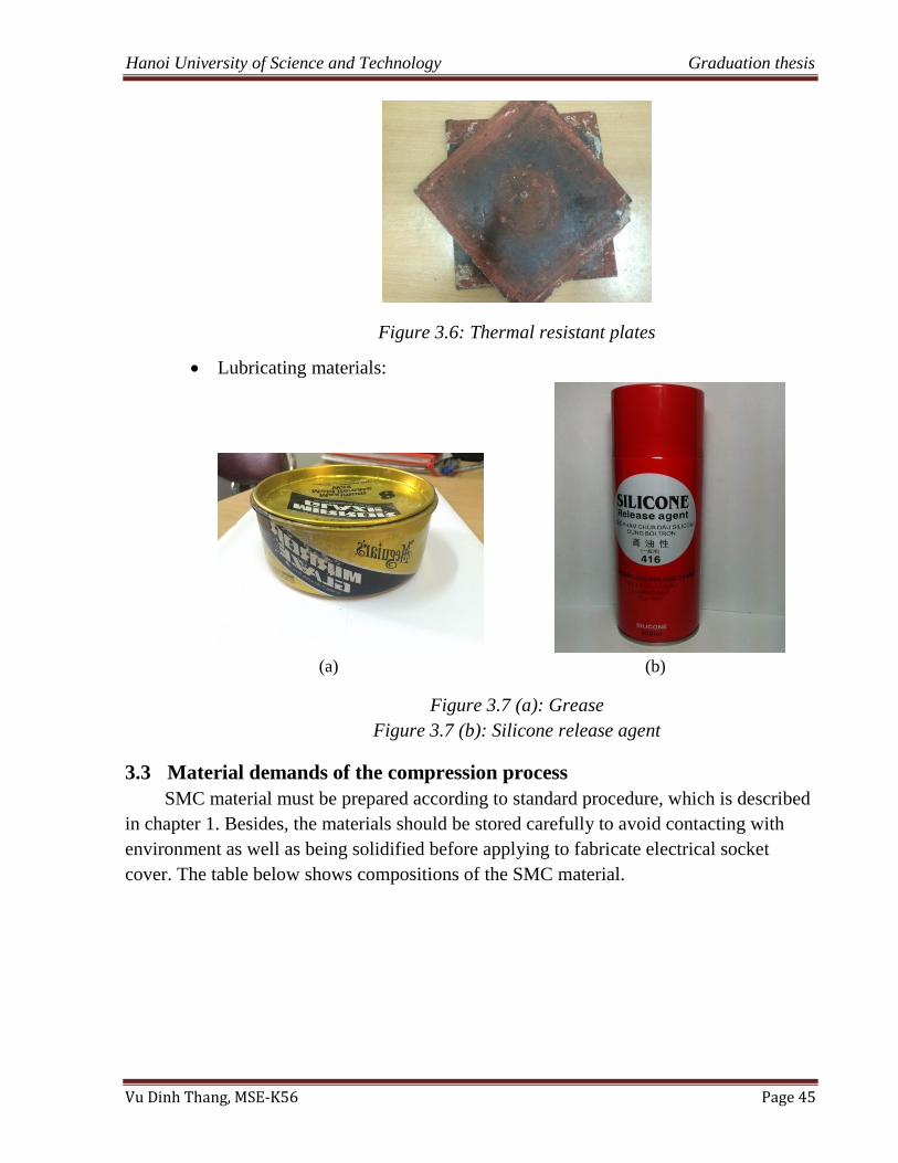
Thermal resistant plates:
In order to decrease heat loss and reduce productivity in compression process,
we use two thermal resistance plates. (Figure 3.6)
Hanoi University of Science and Technology Graduation thesis
Vu Dinh Thang, MSE-K56 Page 45
Figure 3.6: Thermal resistant plates
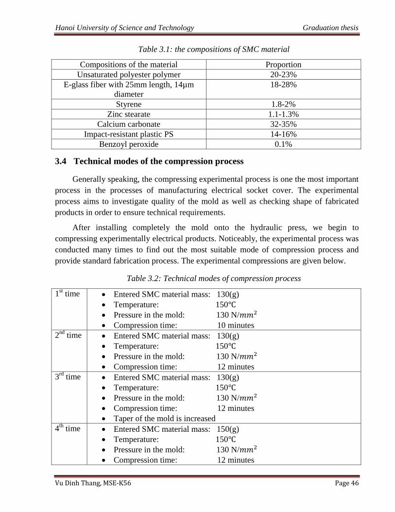
Lubricating materials:
(a) (b)
Figure 3.7 (a): Grease
Figure 3.7 (b): Silicone release agent
3.3 Material demands of the compression process
SMC material must be prepared according to standard procedure, which is described
in chapter 1. Besides, the materials should be stored carefully to avoid contacting with
environment as well as being solidified before applying to fabricate electrical socket
cover. The table below shows compositions of the SMC material.
Hanoi University of Science and Technology Graduation thesis
Vu Dinh Thang, MSE-K56 Page 46
Table 3.1: the compositions of SMC material
Compositions of the material Proportion
Unsaturated polyester polymer 20-23%
E-glass fiber with 25mm length, 14µm
diameter
18-28%
Styrene 1.8-2%
Zinc stearate 1.1-1.3%
Calcium carbonate 32-35%
Impact-resistant plastic PS 14-16%
Benzoyl peroxide 0.1%
3.4 Technical modes of the compression process
Generally speaking, the compressing experimental process is one the most important
process in the processes of manufacturing electrical socket cover. The experimental
process aims to investigate quality of the mold as well as checking shape of fabricated
products in order to ensure technical requirements.
After installing completely the mold onto the hydraulic press, we begin to
compressing experimentally electrical products. Noticeably, the experimental process was
conducted many times to find out the most suitable mode of compression process and
provide standard fabrication process. The experimental compressions are given below.
Table 3.2: Technical modes of compression process
1st time Entered SMC material mass: 130(g)
Temperature: 150
Pressure in the mold: 130 N/
Compression time: 10 minutes
2nd
time Entered SMC material mass: 130(g)
Temperature: 150
Pressure in the mold: 130 N/
Compression time: 12 minutes
3rd
time Entered SMC material mass: 130(g)
Temperature: 150
Pressure in the mold: 130 N/
Compression time: 12 minutes
Taper of the mold is increased
4th
time Entered SMC material mass: 150(g)
Temperature: 150
Pressure in the mold: 130 N/
Compression time: 12 minutes
Hanoi University of Science and Technology Graduation thesis
Vu Dinh Thang, MSE-K56 Page 47
5th
time Entered SMC material mass: 130(g)
Temperature: 150
Pressure in the mold: 150 N/
Compression time: 12 minutes
The mold is coated by chromium
The first time:
Base on calculating mass of electrical sample and properties of sheet molding
compound materials, we set up technical parameters for compression process:
mass of materials is 130(g), temperature is about 150 ; pressure is 130 N/ ,
and compression time is 10 minutes.
- Results: the mold cannot be opened, and product is stuck in the mold.
- Reasons: The material may not have enough time to transform to solid form,
so it stuck in the mold. According calculating and simulating on Deform 3D
software, the material is solidified in 10 minutes at temperature 150 .
However, in the compression process, heat must to transfer from the mold
to the material, so the material may take some time to reach 150 , and the
compression time about 10 minutes is not enough.
- Fixing methods: Firstly, the mold is dismounted off the press, and defective
product is taken out of the mold. Secondly, the compression time is
increased to 12 minutes in the following compression.
The second time:
In the second compression, the compression time is about 12 minutes and the other
parameters are remained unchanged.
- Results: the product cannot be taken out because the material remains stuck
in the mold
Figure 3.8: The second compression result
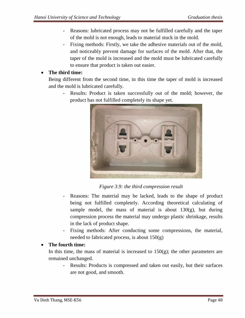
Hanoi University of Science and Technology Graduation thesis
Vu Dinh Thang, MSE-K56 Page 48
- Reasons: lubricated process may not be fulfilled carefully and the taper
of the mold is not enough, leads to material stuck in the mold.
- Fixing methods: Firstly, we take the adhesive materials out of the mold,
and noticeably prevent damage for surfaces of the mold. After that, the
taper of the mold is increased and the mold must be lubricated carefully
to ensure that product is taken out easier.
The third time:
Being different from the second time, in this time the taper of mold is increased
and the mold is lubricated carefully.
- Results: Product is taken successfully out of the mold; however, the
product has not fulfilled completely its shape yet.
Figure 3.9: the third compression result
- Reasons: The material may be lacked, leads to the shape of product
being not fulfilled completely. According theoretical calculating of
sample model, the mass of material is about 130(g), but during
compression process the material may undergo plastic shrinkage, results
in the lack of product shape.
- Fixing methods: After conducting some compressions, the material,
needed to fabricated process, is about 150(g)
The fourth time:
In this time, the mass of material is increased to 150(g); the other parameters are
remained unchanged.
- Results: Products is compressed and taken out easily, but their surfaces
are not good, and smooth.
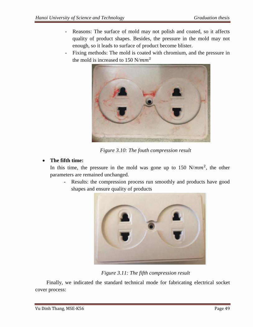
Hanoi University of Science and Technology Graduation thesis
Vu Dinh Thang, MSE-K56 Page 49
- Reasons: The surface of mold may not polish and coated, so it affects
quality of product shapes. Besides, the pressure in the mold may not
enough, so it leads to surface of product become blister.
- Fixing methods: The mold is coated with chromium, and the pressure in
the mold is increased to 150 N/
Figure 3.10: The fouth compression result
The fifth time:
In this time, the pressure in the mold was gone up to 150 N/ , the other
parameters are remained unchanged.
- Results: the compression process run smoothly and products have good
shapes and ensure quality of products
Figure 3.11: The fifth compression result
Finally, we indicated the standard technical mode for fabricating electrical socket
cover process:
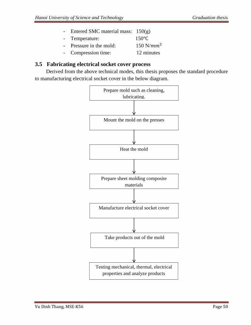
Hanoi University of Science and Technology Graduation thesis
Vu Dinh Thang, MSE-K56 Page 50
- Entered SMC material mass: 150(g)
- Temperature: 150
- Pressure in the mold: 150 N/
- Compression time: 12 minutes
3.5 Fabricating electrical socket cover process
Derived from the above technical modes, this thesis proposes the standard procedure
to manufacturing electrical socket cover in the below diagram.
Prepare mold such as cleaning,
lubricating.
Mount the mold on the presses
Heat the mold
Prepare sheet molding composite
materials
Manufacture electrical socket cover
Take products out of the mold
Testing mechanical, thermal, electrical
properties and analyze products
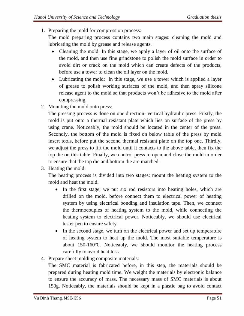
Hanoi University of Science and Technology Graduation thesis
Vu Dinh Thang, MSE-K56 Page 51
1. Preparing the mold for compression process:
The mold preparing process contains two main stages: cleaning the mold and
lubricating the mold by grease and release agents.
Cleaning the mold: In this stage, we apply a layer of oil onto the surface of
the mold, and then use fine grindstone to polish the mold surface in order to
avoid dirt or crack on the mold which can create defects of the products,
before use a tower to clean the oil layer on the mold.
Lubricating the mold: In this stage, we use a tower which is applied a layer
of grease to polish working surfaces of the mold, and then spray silicone
release agent to the mold so that products won‟t be adhesive to the mold after
compressing.
2. Mounting the mold onto press:
The pressing process is done on one direction- vertical hydraulic press. Firstly, the
mold is put onto a thermal resistant plate which lies on surface of the press by
using crane. Noticeably, the mold should be located in the center of the press.
Secondly, the bottom of the mold is fixed on below table of the press by mold
insert tools, before put the second thermal resistant plate on the top one. Thirdly,
we adjust the press to lift the mold until it contacts to the above table, then fix the
top die on this table. Finally, we control press to open and close the mold in order
to ensure that the top die and bottom die are matched.
3. Heating the mold:
The heating process is divided into two stages: mount the heating system to the
mold and heat the mold.
In the first stage, we put six rod resistors into heating holes, which are
drilled on the mold, before connect them to electrical power of heating
system by using electrical bonding and insulation tape. Then, we connect
the thermocouples of heating system to the mold, while connecting the
heating system to electrical power. Noticeably, we should use electrical
tester pen to ensure safety.
In the second stage, we turn on the electrical power and set up temperature
of heating system to heat up the mold. The most suitable temperature is
about 150-160 . Noticeably, we should monitor the heating process
carefully to avoid heat loss.
4. Prepare sheet molding composite materials:
The SMC material is fabricated before, in this step, the materials should be
prepared during heating mold time. We weight the materials by electronic balance
to ensure the accuracy of mass. The necessary mass of SMC materials is about
150g. Noticeably, the materials should be kept in a plastic bag to avoid contact
Hanoi University of Science and Technology Graduation thesis
Vu Dinh Thang, MSE-K56 Page 52
with environment in order to eliminate chemical reactions of the material and
environment or dirt, etc.
5. Manufacture electrical socket cover :
When the temperature reaches 150-160 , we start to manufacture electrical socket
cover. Firstly, we control the press to split the mold (the distance between two dies
should be about 30cm to easily put material to the mold). Secondly, after spraying
silicone release agent to the mold, we put the prepared material into the mold,
before closing the mold. We should use insulation gloves to press the material into
the mold so that it can be filled all cavity of the mold. Thirdly, we close the mold
with slow velocity and then set up pressure for the compression machine. In order
to ensure surface quality as well as the filling of the mold, the pressure should be
about 150 kg/ . The compression time should range from 12 to 15 minutes.
Noticeably, temperature and insulation of the mold should be usually checked in
order to ensure safety.
6. Take products out of the mold:
The process of obtaining product is achieved by using pushing system which is
designed on the mold. Firstly, when the below table of the press is gone down
slowly, the mold will be open and the pushing system will gradually push product
out of the mold. After that, we use gloves to take product out of the mold, then
clean and spray silicone release agents to the mold in order to prepare for the next
compression. Finally, we use a file to eliminate excess of the product as well as
perforate holes for product.
7. Testing mechanical, thermal and electrical properties and analyze products:
In this step, the mechanical, thermal and electrical properties of the product such as
tensile strength, fatigue strength are tested in the laboratory by using the MTS 809
axial/ torsional testing machine or measuring surface resistors machine, etc.
Besides, we also analyze the product quality such as investigating surface quality,
shape and filling of product, etc.
3.6 Summary
In this chapter, the thesis indicated the complete socket cover mold and five
technical modes of experimental compressive process in order to determine the most
suitable mode to manufacture electrical socket cover. Furthermore, based on the standard
procedure, we have manufactured successfully electrical socket cover and in the next
chapter they will be tested mechanical, thermal and electrical properties.
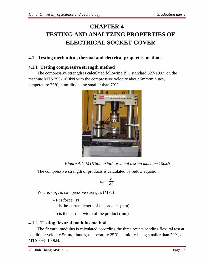
Hanoi University of Science and Technology Graduation thesis
Vu Dinh Thang, MSE-K56 Page 53
CHAPTER 4
4 TESTING AND ANALYZING PROPERTIES OF
ELECTRICAL SOCKET COVER
4.1 Testing mechanical, thermal and electrical properties methods
4.1.1 Testing compressive strength method
The compressive strength is calculated following ISO standard 527-1993, on the
machine MTS 793- 100kN with the compressive velocity about 5mm/minutes,
temperature 25 , humidity being smaller than 70%.
Figure 4.1: MTS 809 axial/ torsional testing machine 100kN
The compressive strength of products is calculated by below equation:
Where: - : is compressive strength, (MPa)
- F is force, (N)
- a is the current length of the product (mm)
- b is the current width of the product (mm)
4.1.2 Testing flexural modulus method
The flexural modulus is calculated according the three points bending flexural test at
condition: velocity 5mm/minutes, temperature 25 , humidity being smaller than 70%, on
MTS 793- 100kN.
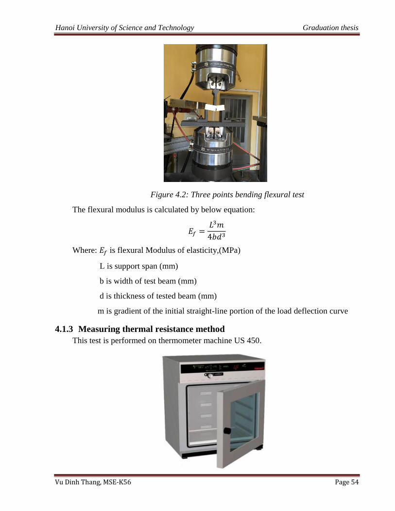
Hanoi University of Science and Technology Graduation thesis
Vu Dinh Thang, MSE-K56 Page 54
Figure 4.2: Three points bending flexural test
The flexural modulus is calculated by below equation:
Where: is flexural Modulus of elasticity,(MPa)
L is support span (mm)
b is width of test beam (mm)
d is thickness of tested beam (mm)
m is gradient of the initial straight-line portion of the load deflection curve
4.1.3 Measuring thermal resistance method
This test is performed on thermometer machine US 450.
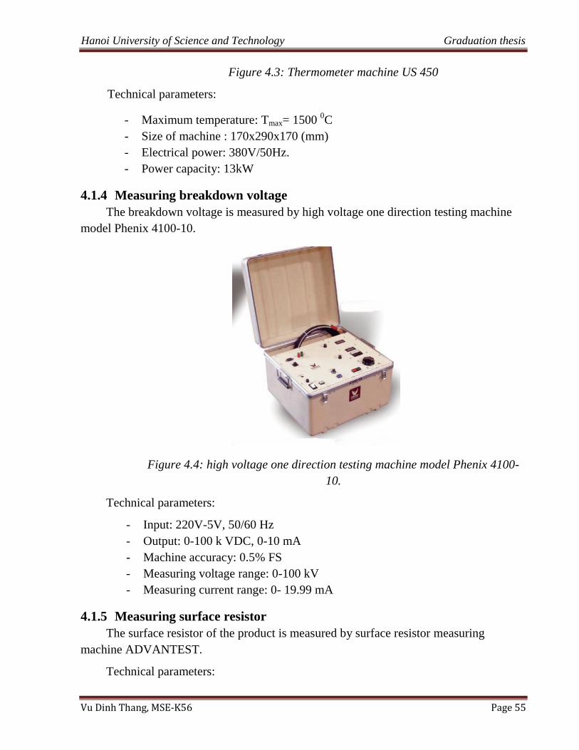
Hanoi University of Science and Technology Graduation thesis
Vu Dinh Thang, MSE-K56 Page 55
Figure 4.3: Thermometer machine US 450
Technical parameters:
- Maximum temperature: Tmax= 1500 0C
- Size of machine : 170x290x170 (mm)
- Electrical power: 380V/50Hz.
- Power capacity: 13kW
4.1.4 Measuring breakdown voltage
The breakdown voltage is measured by high voltage one direction testing machine
model Phenix 4100-10.
Figure 4.4: high voltage one direction testing machine model Phenix 4100-
10.
Technical parameters:
- Input: 220V-5V, 50/60 Hz
- Output: 0-100 k VDC, 0-10 mA
- Machine accuracy: 0.5% FS
- Measuring voltage range: 0-100 kV
- Measuring current range: 0- 19.99 mA
4.1.5 Measuring surface resistor
The surface resistor of the product is measured by surface resistor measuring
machine ADVANTEST.
Technical parameters:
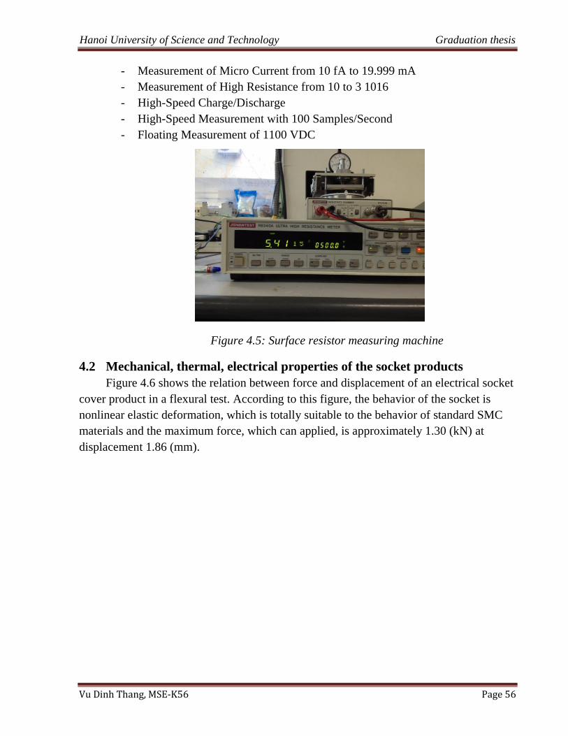
Hanoi University of Science and Technology Graduation thesis
Vu Dinh Thang, MSE-K56 Page 56
- Measurement of Micro Current from 10 fA to 19.999 mA
- Measurement of High Resistance from 10 to 3 1016
- High-Speed Charge/Discharge
- High-Speed Measurement with 100 Samples/Second
- Floating Measurement of 1100 VDC
Figure 4.5: Surface resistor measuring machine
4.2 Mechanical, thermal, electrical properties of the socket products
Figure 4.6 shows the relation between force and displacement of an electrical socket
cover product in a flexural test. According to this figure, the behavior of the socket is
nonlinear elastic deformation, which is totally suitable to the behavior of standard SMC
materials and the maximum force, which can applied, is approximately 1.30 (kN) at
displacement 1.86 (mm).
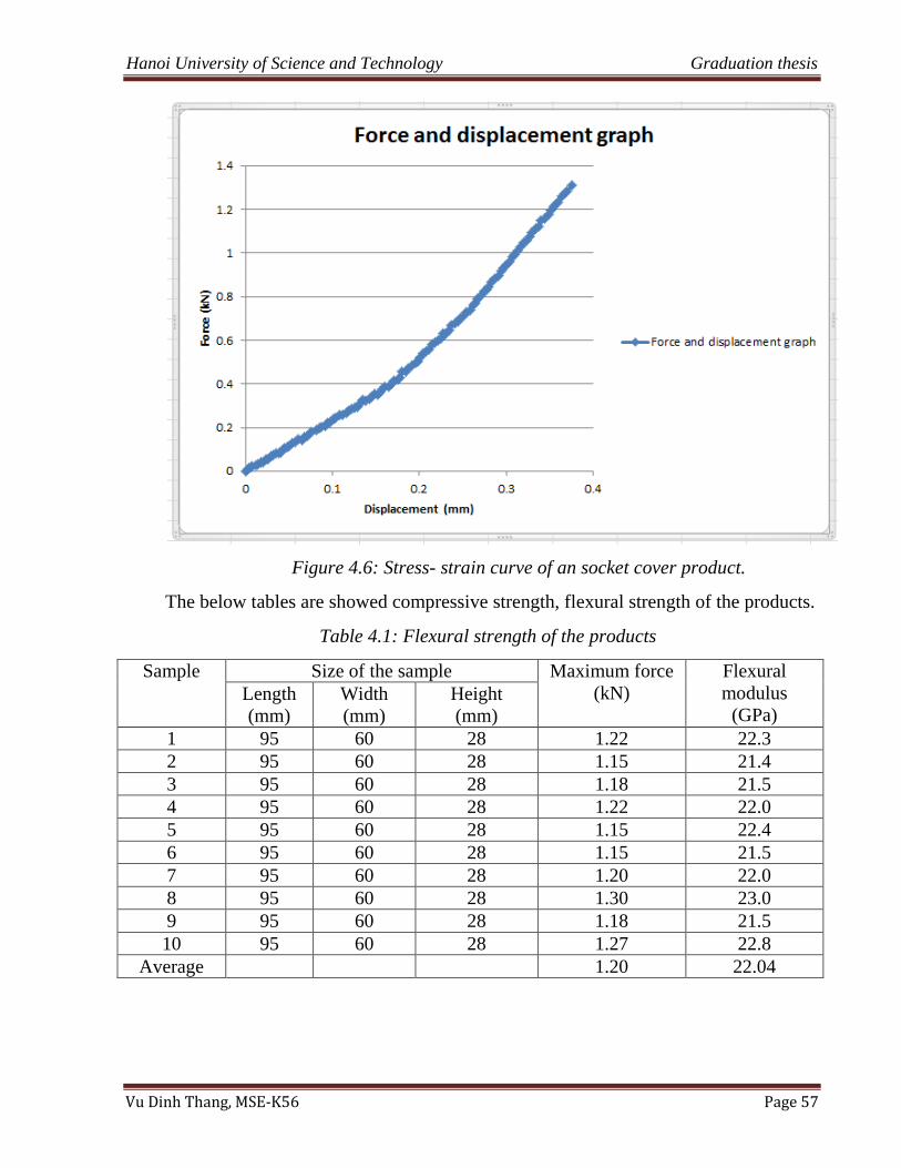
Hanoi University of Science and Technology Graduation thesis
Vu Dinh Thang, MSE-K56 Page 57
Figure 4.6: Stress- strain curve of an socket cover product.
The below tables are showed compressive strength, flexural strength of the products.
Table 4.1: Flexural strength of the products
Sample Size of the sample Maximum force
(kN)
Flexural
modulus
(GPa) Length
(mm)
Width
(mm)
Height
(mm)
1 95 60 28 1.22 22.3
2 95 60 28 1.15 21.4
3 95 60 28 1.18 21.5
4 95 60 28 1.22 22.0
5 95 60 28 1.15 22.4
6 95 60 28 1.15 21.5
7 95 60 28 1.20 22.0
8 95 60 28 1.30 23.0
9 95 60 28 1.18 21.5
10 95 60 28 1.27 22.8
Average 1.20 22.04
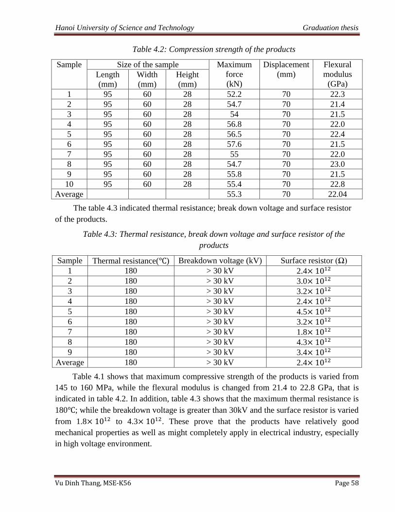
Hanoi University of Science and Technology Graduation thesis
Vu Dinh Thang, MSE-K56 Page 58
Table 4.2: Compression strength of the products
Sample Size of the sample Maximum
force
(kN)
Displacement
(mm)
Flexural
modulus
(GPa) Length
(mm)
Width
(mm)
Height
(mm)
1 95 60 28 52.2 70 22.3
2 95 60 28 54.7 70 21.4
3 95 60 28 54 70 21.5
4 95 60 28 56.8 70 22.0
5 95 60 28 56.5 70 22.4
6 95 60 28 57.6 70 21.5
7 95 60 28 55 70 22.0
8 95 60 28 54.7 70 23.0
9 95 60 28 55.8 70 21.5
10 95 60 28 55.4 70 22.8
Average 55.3 70 22.04
The table 4.3 indicated thermal resistance; break down voltage and surface resistor
of the products.
Table 4.3: Thermal resistance, break down voltage and surface resistor of the
products
Sample Thermal resistance( ) Breakdown voltage (kV) Surface resistor (Ω)
1 180 > 30 kV 2.4
2 180 > 30 kV 3.0
3 180 > 30 kV 3.2
4 180 > 30 kV 2.4
5 180 > 30 kV 4.5
6 180 > 30 kV 3.2
7 180 > 30 kV 1.8
8 180 > 30 kV 4.3
9 180 > 30 kV 3.4
Average 180 > 30 kV 2.4
Table 4.1 shows that maximum compressive strength of the products is varied from
145 to 160 MPa, while the flexural modulus is changed from 21.4 to 22.8 GPa, that is
indicated in table 4.2. In addition, table 4.3 shows that the maximum thermal resistance is
180 ; while the breakdown voltage is greater than 30kV and the surface resistor is varied
from 1.8 to 4.3 . These prove that the products have relatively good
mechanical properties as well as might completely apply in electrical industry, especially
in high voltage environment.
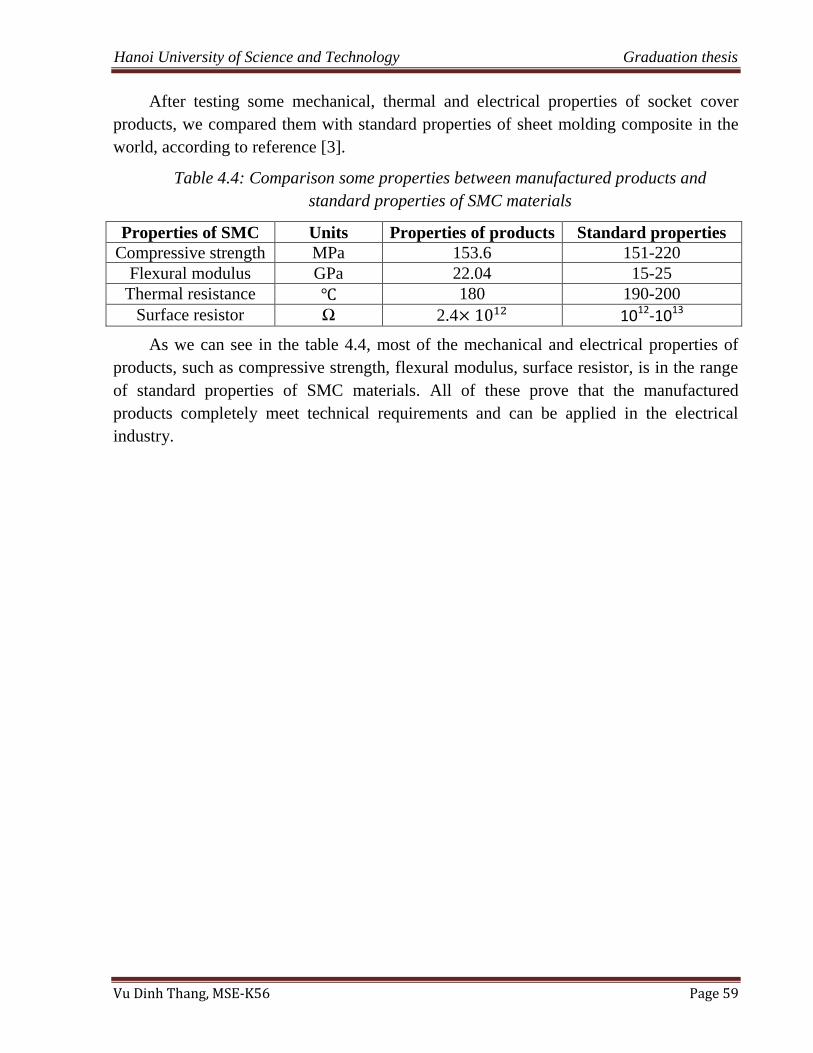
Hanoi University of Science and Technology Graduation thesis
Vu Dinh Thang, MSE-K56 Page 59
After testing some mechanical, thermal and electrical properties of socket cover
products, we compared them with standard properties of sheet molding composite in the
world, according to reference [3].
Table 4.4: Comparison some properties between manufactured products and
standard properties of SMC materials
Properties of SMC Units Properties of products Standard properties
Compressive strength MPa 153.6 151-220
Flexural modulus GPa 22.04 15-25
Thermal resistance 180 190-200
Surface resistor Ω 2.4 1012-1013
As we can see in the table 4.4, most of the mechanical and electrical properties of
products, such as compressive strength, flexural modulus, surface resistor, is in the range
of standard properties of SMC materials. All of these prove that the manufactured
products completely meet technical requirements and can be applied in the electrical
industry.
Hanoi University of Science and Technology Graduation thesis
Vu Dinh Thang, MSE-K56 Page 60
CONCLUSIONS
Based on the testing mechanical, thermal and electrical results of socket cover
products, we can conclude that:
Manufactured the complete mold of electrical socket cover as well as fabricating
electrical socket cover.
After testing properties of products, we concluded that the manufactured sockets are
totally met technical requirements in order to apply in electrical industry.
Indicated successful fabrication process of electrical socket cover as well as applied in
electrical industry.
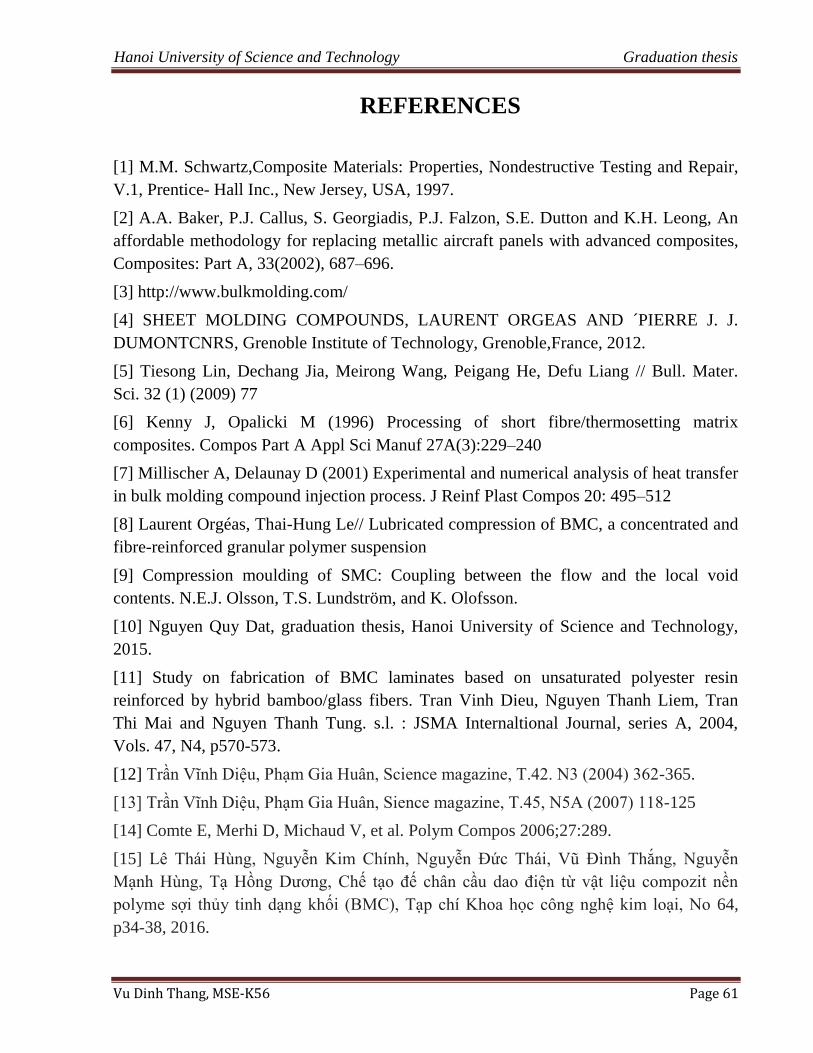
Hanoi University of Science and Technology Graduation thesis
Vu Dinh Thang, MSE-K56 Page 61
REFERENCES
[1] M.M. Schwartz,Composite Materials: Properties, Nondestructive Testing and Repair,
V.1, Prentice- Hall Inc., New Jersey, USA, 1997.
[2] A.A. Baker, P.J. Callus, S. Georgiadis, P.J. Falzon, S.E. Dutton and K.H. Leong, An
affordable methodology for replacing metallic aircraft panels with advanced composites,
Composites: Part A, 33(2002), 687–696.
[3] http://www.bulkmolding.com/
[4] SHEET MOLDING COMPOUNDS, LAURENT ORGEAS AND ´PIERRE J. J.
DUMONTCNRS, Grenoble Institute of Technology, Grenoble,France, 2012.
[5] Tiesong Lin, Dechang Jia, Meirong Wang, Peigang He, Defu Liang // Bull. Mater.
Sci. 32 (1) (2009) 77
[6] Kenny J, Opalicki M (1996) Processing of short fibre/thermosetting matrix
composites. Compos Part A Appl Sci Manuf 27A(3):229–240
[7] Millischer A, Delaunay D (2001) Experimental and numerical analysis of heat transfer
in bulk molding compound injection process. J Reinf Plast Compos 20: 495–512
[8] Laurent Orgéas, Thai-Hung Le// Lubricated compression of BMC, a concentrated and
fibre-reinforced granular polymer suspension
[9] Compression moulding of SMC: Coupling between the flow and the local void
contents. N.E.J. Olsson, T.S. Lundström, and K. Olofsson.
[10] Nguyen Quy Dat, graduation thesis, Hanoi University of Science and Technology,
2015.
[11] Study on fabrication of BMC laminates based on unsaturated polyester resin
reinforced by hybrid bamboo/glass fibers. Tran Vinh Dieu, Nguyen Thanh Liem, Tran
Thi Mai and Nguyen Thanh Tung. s.l. : JSMA Internaltional Journal, series A, 2004,
Vols. 47, N4, p570-573.
[12] Trần Vĩnh Diệu, Phạm Gia Huân, Science magazine, T.42. N3 (2004) 362-365.
[13] Trần Vĩnh Diệu, Phạm Gia Huân, Sience magazine, T.45, N5A (2007) 118-125
[14] Comte E, Merhi D, Michaud V, et al. Polym Compos 2006;27:289.
[15] Lê Thái Hùng, Nguyễn Kim Chính, Nguyễn Đức Thái, Vũ Đình Thắng, Nguyễn
Mạnh Hùng, Tạ Hồng Dương, Chế tạo đế chân cầu dao điện từ vật liệu compozit nền
polyme sợi thủy tinh dạng khối (BMC), Tạp chí Khoa học công nghệ kim loại, No 64,
p34-38, 2016.
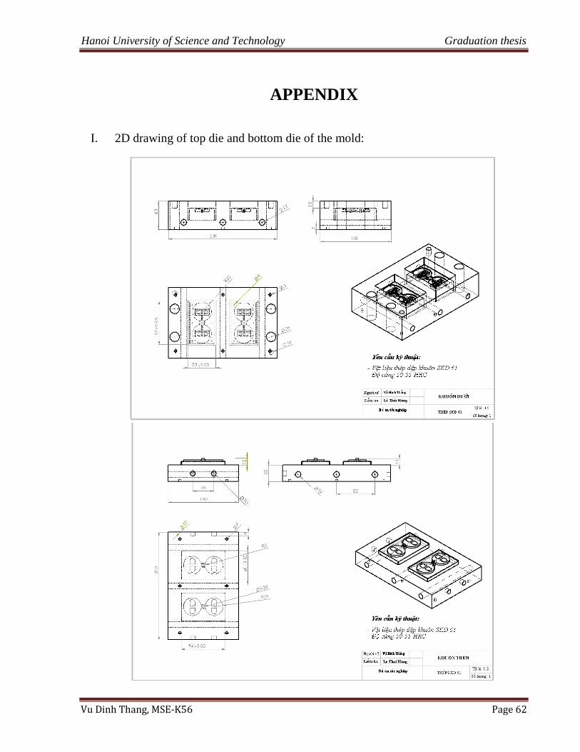
Hanoi University of Science and Technology Graduation thesis
Vu Dinh Thang, MSE-K56 Page 62
5 APPENDIX
I. 2D drawing of top die and bottom die of the mold:
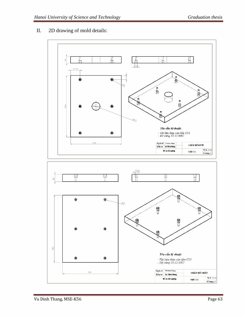
Hanoi University of Science and Technology Graduation thesis
Vu Dinh Thang, MSE-K56 Page 63
II. 2D drawing of mold details:
Hanoi University of Science and Technology Graduation thesis
Vu Dinh Thang, MSE-K56 Page 64
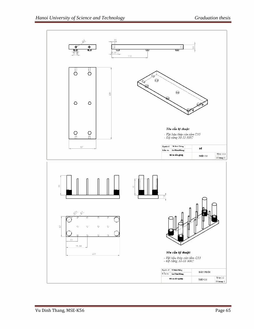
Hanoi University of Science and Technology Graduation thesis
Vu Dinh Thang, MSE-K56 Page 65
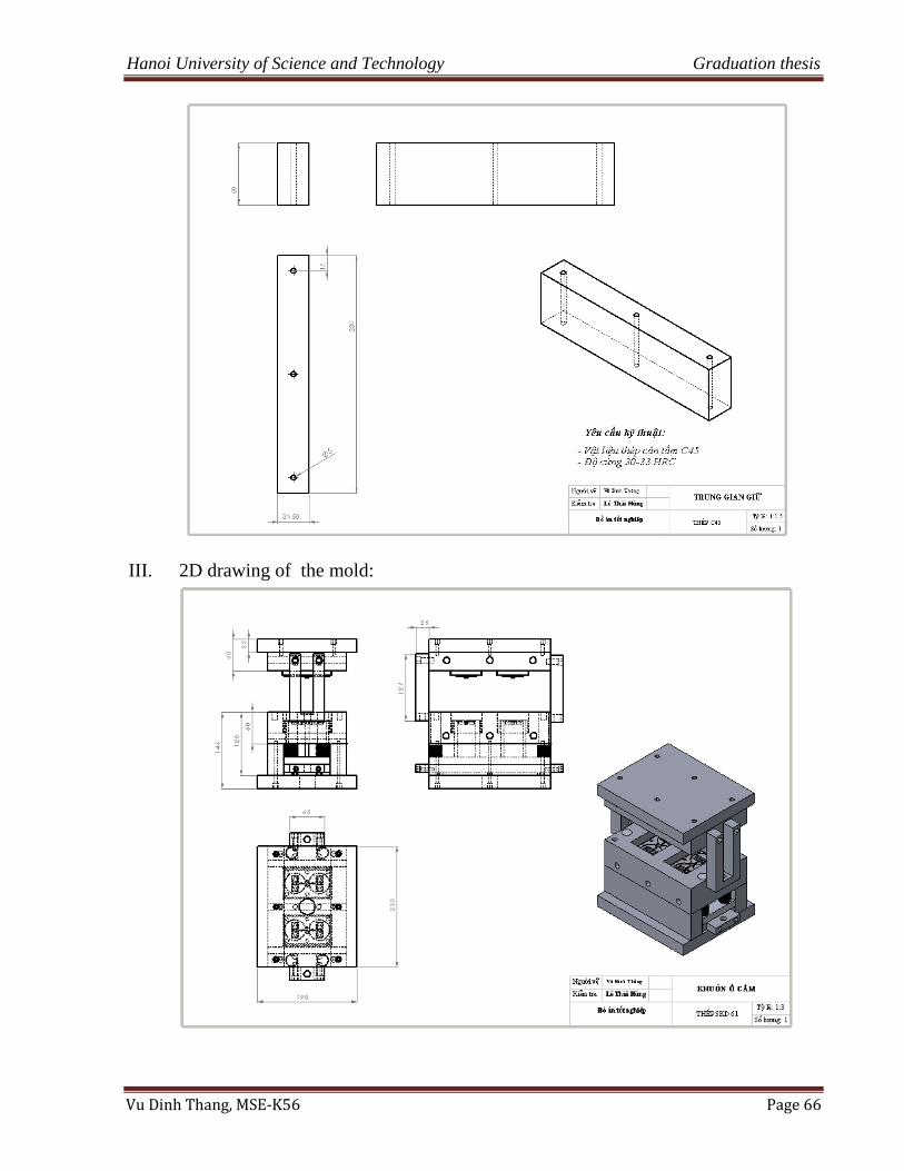
Hanoi University of Science and Technology Graduation thesis
Vu Dinh Thang, MSE-K56 Page 66
III. 2D drawing of the mold: