Embed Size (px)
Citation preview
Grape Solar 400 Watt Off Grid Kit
(GS-400-KIT)
www.grapesolar.com Tel. 1-877-264-1014 (toll free), 1-541-349-9000, Fax: 1-541-343-9000
1
©Copyright 2016, Grape Solar, Inc. All Rights Reserved
For additional information about this kit visit grapesolar.com/products, or
email [email protected]
GS-100+KIT EXPANDABLE PHOTOVOLTAIC POWER GENERATION SYSTEM CONFIGURATION MANUAL Rev. 140304
Valid from Jan. 2016
www.grapesolar.com Tel. 1-877-264-1014 (toll free), 1-541-349-9000, Fax: 1-541-343-9000
2 Valid from Jan. 2016
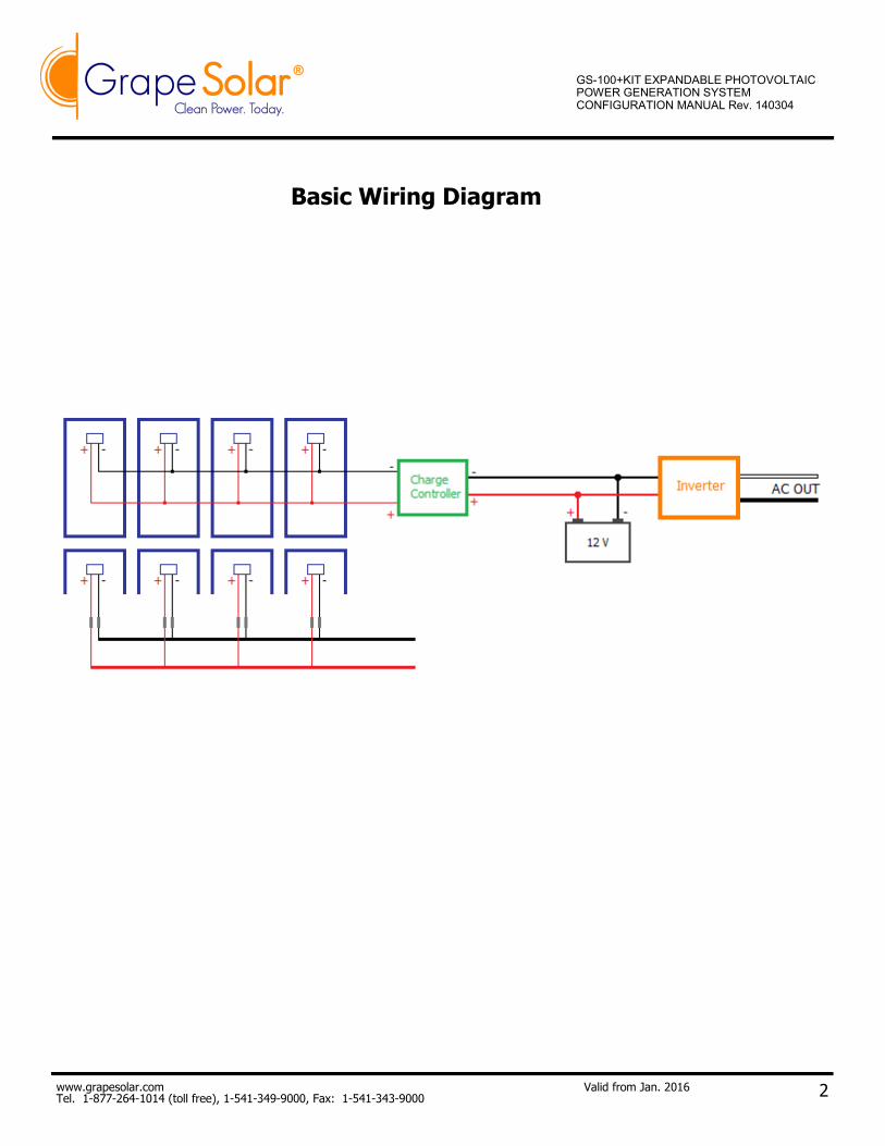
Basic Wiring Diagram
GS-100+KIT EXPANDABLE PHOTOVOLTAIC POWER GENERATION SYSTEM CONFIGURATION MANUAL Rev. 140304
www.grapesolar.com Tel. 1-877-264-1014 (toll free), 1-541-349-9000, Fax: 1-541-343-9000
3
QuickStart Setup
Valid from July 2015
GS-100-Basic PHOTOVOLTAIC POWER GEN-ERATION SYSTEM CONFIGURATION MANUAL Rev. 140303
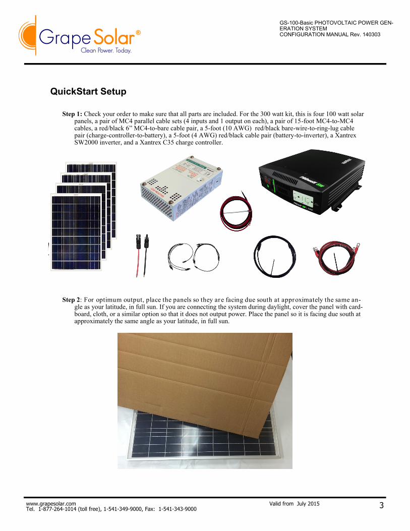
Step 1: Check your order to make sure that all parts are included. For the 300 watt kit, this is four 100 watt solar panels, a pair of MC4 parallel cable sets (4 inputs and 1 output on each), a pair of 15-foot MC4-to-MC4 cables, a red/black 6” MC4-to-bare cable pair, a 5-foot (10 AWG) red/black bare-wire-to-ring-lug cable pair (charge-controller-to-battery), a 5-foot (4 AWG) red/black cable pair (battery-to-inverter), a Xantrex SW2000 inverter, and a Xantrex C35 charge controller.
Step 2: For optimum output, place the panels so they are facing due south at approximately the same an-gle as your latitude, in full sun. If you are connecting the system during daylight, cover the panel with card-board, cloth, or a similar option so that it does not output power. Place the panel so it is facing due south at approximately the same angle as your latitude, in full sun.
www.grapesolar.com Tel. 1-877-264-1014 (toll free), 1-541-349-9000, Fax: 1-541-343-9000
4
QuickStart Setup
Valid from July 2015
GS-100-Basic PHOTOVOLTAIC POWER GEN-ERATION SYSTEM CONFIGURATION MANUAL Rev. 140303
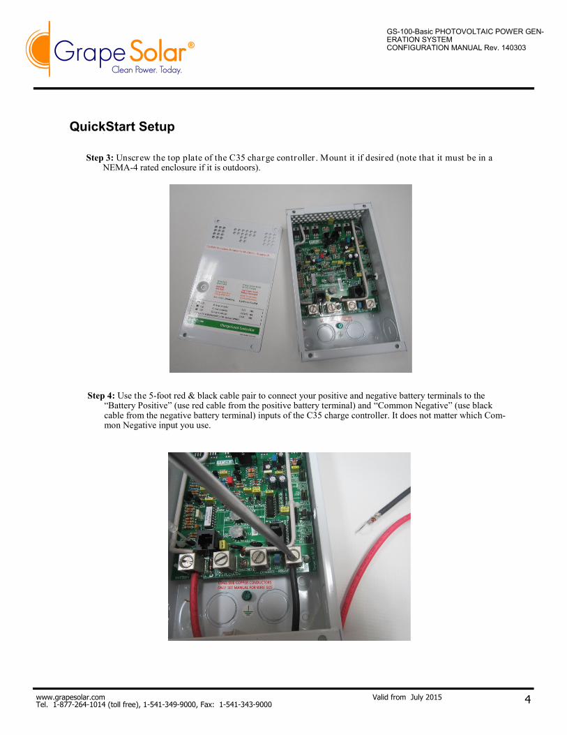
Step 4: Use the 5-foot red & black cable pair to connect your positive and negative battery terminals to the “Battery Positive” (use red cable from the positive battery terminal) and “Common Negative” (use black cable from the negative battery terminal) inputs of the C35 charge controller. It does not matter which Com-mon Negative input you use.
Step 3: Unscrew the top plate of the C35 charge controller . Mount it if desired (note that it must be in a NEMA-4 rated enclosure if it is outdoors).
www.grapesolar.com Tel. 1-877-264-1014 (toll free), 1-541-349-9000, Fax: 1-541-343-9000
5
QuickStart Setup
Valid from July 2015
GS-100-Basic PHOTOVOLTAIC POWER GEN-ERATION SYSTEM CONFIGURATION MANUAL Rev. 140303
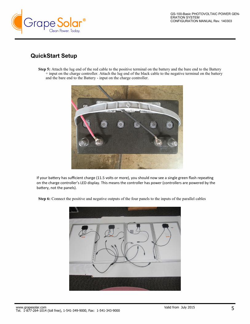
Step 6: Connect the positive and negative outputs of the four panels to the inputs of the parallel cables
Step 5: Attach the lug end of the red cable to the positive terminal on the battery and the bare end to the Battery + input on the charge controller. Attach the lug end of the black cable to the negative terminal on the battery and the bare end to the Battery - input on the charge controller.
If your battery has sufficient charge (11.5 volts or more), you should now see a single green flash repeating on the charge controller’s LED display. This means the controller has power (controllers are powered by the battery, not the panels).
www.grapesolar.com Tel. 1-877-264-1014 (toll free), 1-541-349-9000, Fax: 1-541-343-9000
6
QuickStart Setup
Valid from July 2015
GS-100-Basic PHOTOVOLTAIC POWER GEN-ERATION SYSTEM CONFIGURATION MANUAL Rev. 140303
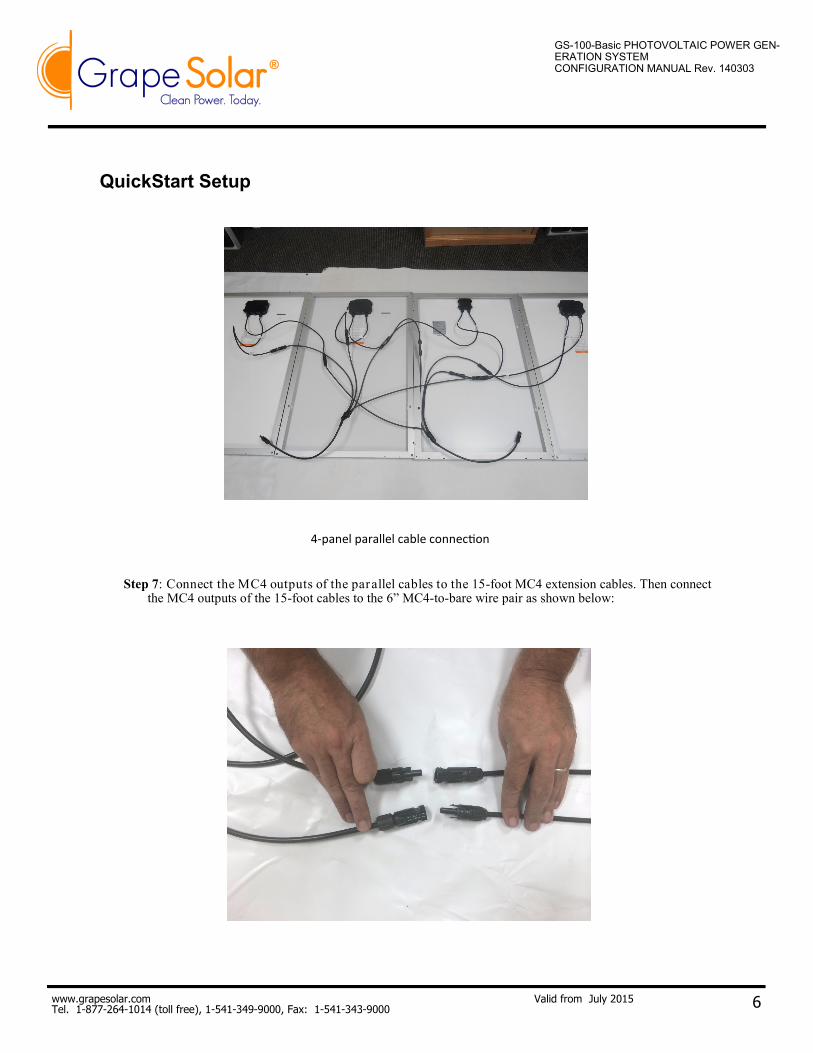
Step 7: Connect the MC4 outputs of the parallel cables to the 15-foot MC4 extension cables. Then connect the MC4 outputs of the 15-foot cables to the 6” MC4-to-bare wire pair as shown below:
4-panel parallel cable connection
www.grapesolar.com Tel. 1-877-264-1014 (toll free), 1-541-349-9000, Fax: 1-541-343-9000
7
QuickStart Setup
Valid from July 2015
GS-100-Basic PHOTOVOLTAIC POWER GEN-ERATION SYSTEM CONFIGURATION MANUAL Rev. 140303
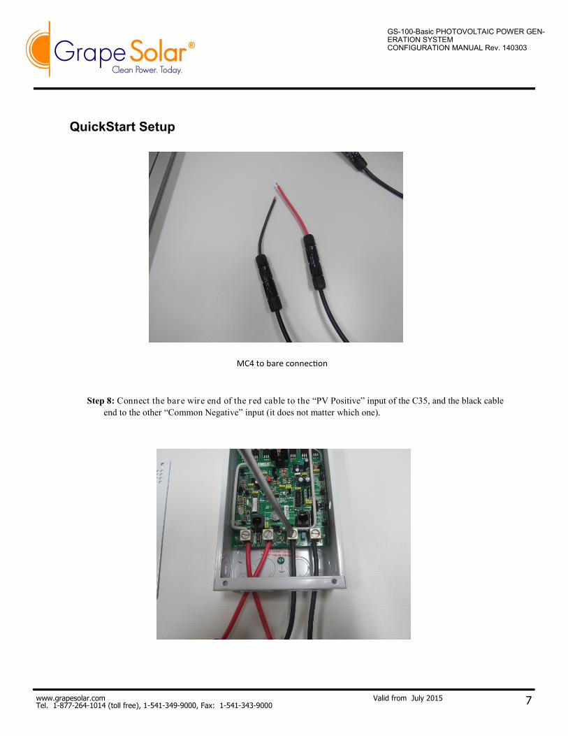
Step 8: Connect the bare wire end of the red cable to the “PV Positive” input of the C35, and the black cable
end to the other “Common Negative” input (it does not matter which one).
MC4 to bare connection
www.grapesolar.com Tel. 1-877-264-1014 (toll free), 1-541-349-9000, Fax: 1-541-343-9000
8
QuickStart Setup
Valid from July 2015
GS-100-Basic PHOTOVOLTAIC POWER GEN-ERATION SYSTEM CONFIGURATION MANUAL Rev. 140303
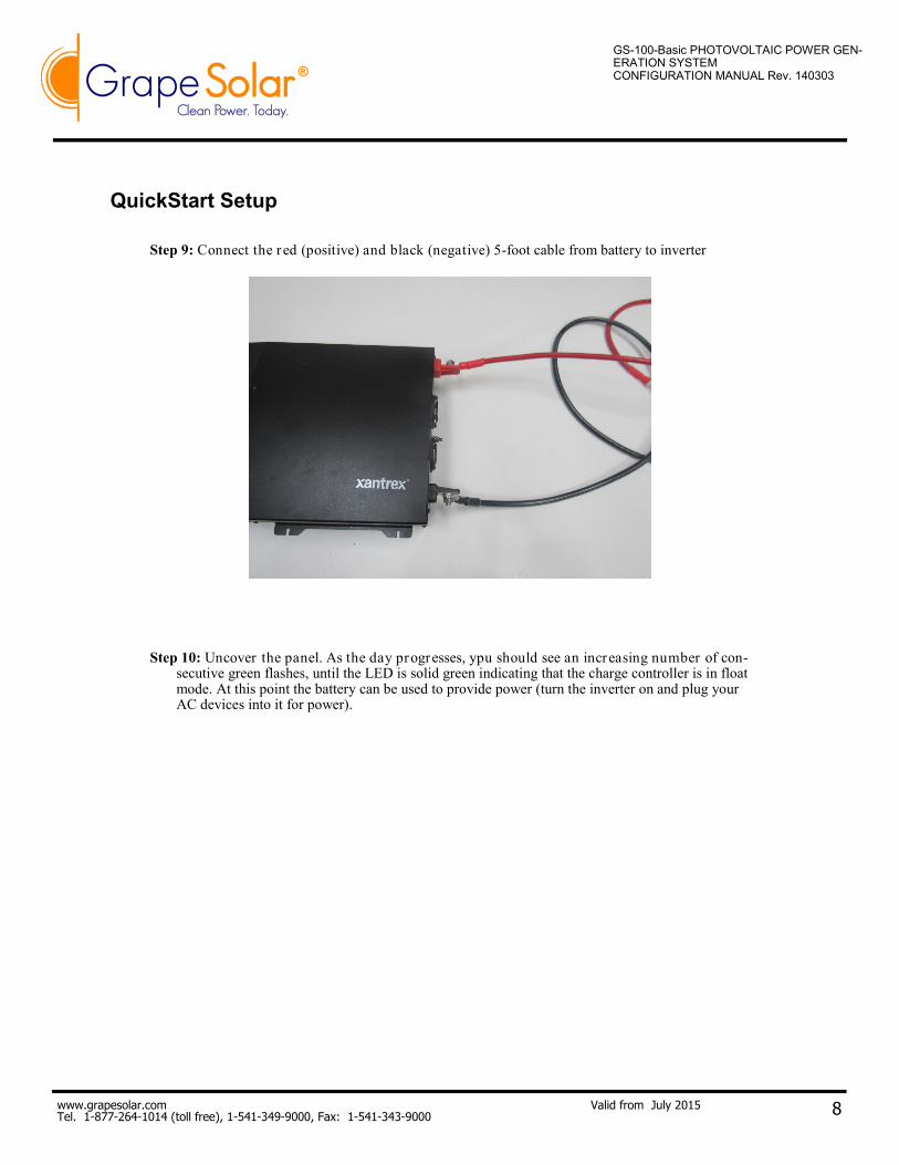
Step 9: Connect the red (positive) and black (negative) 5-foot cable from battery to inverter
Step 10: Uncover the panel. As the day progresses, ypu should see an increasing number of con-secutive green flashes, until the LED is solid green indicating that the charge controller is in float mode. At this point the battery can be used to provide power (turn the inverter on and plug your AC devices into it for power).