Embed Size (px)
Citation preview
Reciprocating Compressors for industrial refrig-erationGrasso
Maintenance checklistpador9130gbr_6
COPYRIGHT
All Rights reserved. No part of this publication may be copied or published bymeans of printing, photocopying, microfilm or otherwise without prior written con-sent of Grasso.This restriction also applies to the corresponding drawings and diagrams.
LEGAL NOTICE
This publication has been written in good faith. However, Grasso cannot be heldresponsible, neither for any errors occurring in this publication nor for their conse-quences.
pador9130gbr_62 15.03.2017
SAFETY INSTRUCTIONS
Hint!
This manual must be carefully read and understood prior to installingand servicing the compressor (package)
General Safety
All service operations described in this servicemanual are only to be carried outby well-trained/qualified personnel and even then only after this service manualhas been read carefully and is fully understood.
Personal safety
Observe all (inter)national and/or local safety standards, measures and regula-tions during reinstalling, repairing and connecting the compressor (package).
Mechanical safety
If the compressor does not have to be removed from its base, it is advisable toput warning labels on vital parts of the compressor saying that the plant is out-of-operation and must not be started up.If the compressor has to be opened for service,the refrigerant has to be pumpeddown and the electric supply has to be cut off.After having run the initial 100 operating hours,it is essential (in both new andmodified plants) to replace the red running-in discharge oil filter element with thepermanent grey filter element. Also replace the running-in suction gas filter ele-ment.Check the direction of rotation is correct before re-starting the compressor.
pador9130gbr_6 15.03.2017 3
PREFACE
General
1. All documentation can be downloaded via our web site.
2. Grasso’s technical manuals includes “generic paragraphs”; this means that itcan occur that not all data as described is relevant for the current compres-sor series as mentioned in this manual. (For instance, not all compressor ser-ies are suitable for all mentioned refrigerants or not all compressor seriesincludes two-stage compressors)
Directives
Equipment is based on Pressure Equipment Directive (PED 97/23/EG) regula-tions and according to Machine Directive (MD 2006/42/EG) regulations.
The applied standards are:NEN-EN-IEC 60204, NEN-EN-ISO 12100, NEN-EN-ISO 13857, NEN-EN 378
pador9130gbr_64 15.03.2017
NEVER CHANGE POSITIONS!
Warning
Never change positions of parts when re-assembling the compressor.E.g. cylinder liners, suction valves, discharge valves and relief valveshave to be replaced always in the origional position.
pador9130gbr_6 15.03.2017 5

pador9130gbr_66 15.03.2017
TABLE OF CONTENTS1 MAINTENANCE 91.1 Replacement piston rings and cylinder liners 91.2 Running-in oil filter has to be installed after an overhaul or big repair 101.3 SMS FACTOR 101.4 Legend 111.5 Description Maintenance ABC when GMM is applied 111.5.1 Compressor 121.5.2 Package components 141.6 Grasso V 300 .. 1800 (T), WITHOUT GMM 151.7 Grasso VCM (CLASSIC MECHANISM, Nmax=1000 min-1 191.8 Grasso 5HP R744 & R717 221.9 Grasso 12E 251.10 Grasso 12 291.11 Grasso 10 321.12 Grasso 6 371.13 Grasso 7S and Grasso 8S 401.14 Grasso 11 (RC11) and Grasso 9 (RC9) 421.15 Checklist 44
pador9130gbr_6 15.03.2017 7
pador9130gbr_68 15.03.2017
1 MAINTENANCE
1.1 Replacement piston rings and cylinder liners
Hint!
Recommendation/warning!For major overhauls or every repair where piston rings are beingreplaced it is strongly recommended to replace the cylinder liners aswell. This is very important for the next reasons:
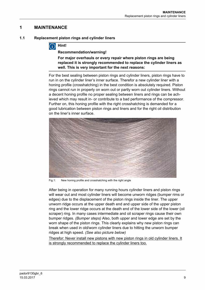
For the best sealing between piston rings and cylinder liners, piston rings have torun in on the cylinder liner’s inner surface. Therefor a new cylinder liner with ahoning profile (crosshatching) in the best condition is absolutely required. Pistonrings cannot run in properly on worn out or partly worn out cylinder liners. Withouta decent honing profile no proper sealing between liners and rings can be ach-ieved which may result in- or contribute to a bad performance of the compressor.Further on, this honing profile with the right crosshatching is demanded for agood lubrication between piston rings and liners and for the right oil distributionon the liner’s inner surface.
Fig.1: New honing profile and crosshatching with the right angle
After being in operation for many running hours cylinder liners and piston ringswill wear out and most cylinder liners will become unworn ridges (bumper rims oredges) due to the displacement of the piston rings inside the liner. The upperunworn ridge occurs at the upper death end and upper side of the upper pistonring and the lower ridge occurs at the death end of the lower side of the lower (oilscraper) ring. In many cases intermediate and oil scraper rings cause their ownbumper ridges. (Bumper steps) Also, both upper and lower edge are set by theworn shape of the piston rings. This clearly explains why new piston rings canbreak when used in old/worn cylinder liners due to hitting the unworn bumperridges at high speed. (See also picture below)Therefor: Never install new pistons with new piston rings in old cylinder liners. Itis strongly recommended to replace the cylinder liners too.
MAINTENANCEReplacement piston rings and cylinder liners
pador9130gbr_6 15.03.2017 9
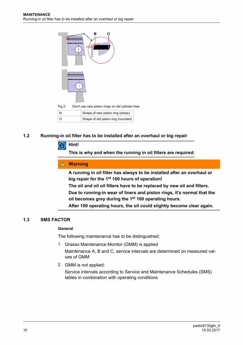
Fig.2: Don't use new piston rings on old cylinder liner
N Shape of new piston ring (sharp)
O Shape of old piston ring (rounded)
1.2 Running-in oil filter has to be installed after an overhaul or big repair
Hint!
This is why and when the running in oil filters are required:
Warning
A running in oil filter has always to be installed after an overhaul orbig repair for the 1st 100 hours of operation!The oil and oil oil filters have to be replaced by new oil and filters.Due to running-in wear of liners and piston rings, it's normal that theoil becomes grey during the 1st 100 operating hours.After 100 operating hours, the oil could slightly become clear again.
1.3 SMS FACTOR
General
The following maintenance has to be distinguished:
1. Grasso Maintenance Monitor (GMM) is appliedMaintenance A, B and C, service intervals are determined on measured val-ues of GMM
2. GMM is not applied:Service intervals according to Service and Maintenance Schedules (SMS)tables in combination with operating conditions
MAINTENANCERunning-in oil filter has to be installed after an overhaul or big repair
pador9130gbr_610 15.03.2017
Warning
GMM is not used: The running hours mentioned in the SMS tablesshould only be used as a reference for maintenance intervals.The number of running hours mentioned in the SMS tables have to beadjusted accordingly depending on the operating conditions of thecompressor (speed, evaporating temperature, condensing tempera-ture, refrigerant, start frequency, capacity control steps, etc.. Thismeans that the service intervals could be significantly different.The running hours mentioned in the tables are based on a single stagecompressor running at -10oC/+35oC, NH3 at nominal speed. In thiscase the SMS factor = 1, in all other cases the maintenance intervalshave to be adjusted accordingly.
1.4 Legend
Warning
These operations cover routine maintenance and are meant as a guideonly. Lack of maintenance, frequency of stop/starting, extreme operat-ing conditions etc could lead to accelerated wear.
General;
The service and maintenance schedules use the codes as explained in the tablebelow;
Actions
Legend for service and maintenance schedules (SMS)
Item Code/Actions Description
1 IC Inspection / Alternatively renewal - correcting / Testing
2 IV Inspection Visual / Alternatively electrical testing
3 RE Renewal
4 ME Measure
5 CL Clean
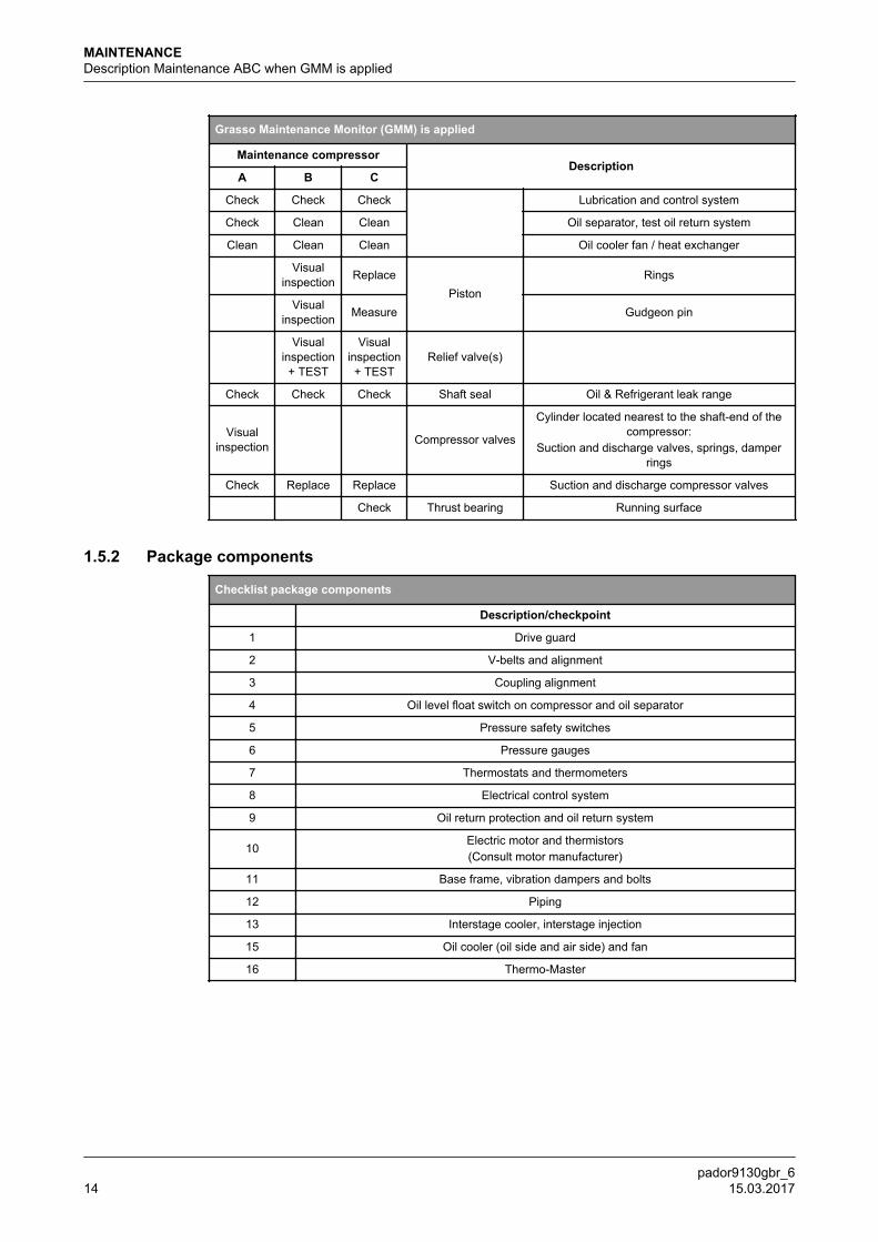
1.5 Description Maintenance ABC when GMM is appliedThe information in this section has to be used when GMM is applied.
Hint!
This section is only valid in case the Grasso Maintenance Monitor(GMM) is applied.
General
The following maintenance has to be distinguished;
1. Small maintenance, Maintenance A, Yearly inspection
2. Medium maintenance, Maintenance B
MAINTENANCELegend
pador9130gbr_6 15.03.2017 11
3. Large maintenance, Maintenance C
Description maintenance A;
1. Replace/clean oil discharge filter, clean oil suction filter
2. Visual inspection of cylinders and crankcase
3. Visual inspection of cylinder no. 1
4. Check compressor running conditions
5. Check/test safety equipment
Description maintenance B;
1. Maintenance A +
2. Replace suction and discharge valve rings and springs (“top end“ overhaul)
3. Inspection of pistons and cylinder liners
Description maintenance C;
1. Maintenance B +
2. Major inspection/overhaul;Depending on requirements and expectations, required actions have to betaken. (complete disassembly, replacement of bearings, inspection/replace-ment of all main components like crankshaft, cylinder liners, pistons, ...)
1.5.1 Compressor
General remarks about check list;
1. Check list for compressor only; all other components have to be maintainedaccording to their specific manuals (IMM and SIM).
2. All items of the list below marked “check“, have to be checked visually andchecked for proper working.
3. Some components have to be measured.For measuring details refer to SIM.
4. Measuring means also that visual inspection is required.
5. Visual inspections:The visual inspections during maintenance are of importance; measurementsshould be carried out at the moment that visually abnormalities are detected.The result of the inspection determines whether one or more parts have to bereplaced. For more detailed information refer (SIM) and Installation and Main-tenance Manual (IMM).
MAINTENANCEDescription Maintenance ABC when GMM is applied
pador9130gbr_612 15.03.2017
6. Oil and oil return systems:The quality of the oil effects the oil consumption and the life time of the mov-ing parts. For oil return systems or systems in which soluble oil is being used,we advise to check (or have checked) the quality of the oil every 5000 hoursand - if necessary - to renew the oil and/or filters. If there is no oil analysisavailable, we advise to renew the oil. By regularly carrying out oil analysesand registering them in a log, aberrations will be noticed in an early stage,which may prevent or reduce resultant damage(s).
Note 1:When renewing the oil, in the crankcase the oil in the oil separator and the oilreturn or oil rectifier system (if fitted) has to be renewed.
Note 2:Pre-lubricate the compressor before re-starting. Used or filtered oil shouldNEVER be added to a compressor under any circumstance. Use only new oilas selected from the Grasso oil table. Oil charging via the suction line of thecompressor is not allowed.
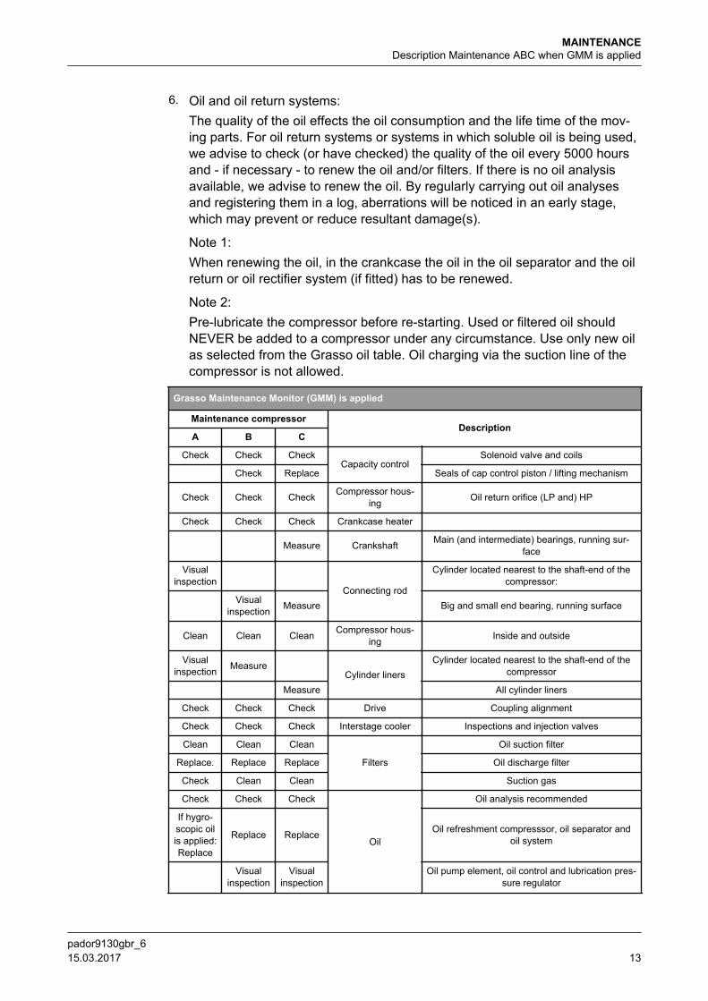
Grasso Maintenance Monitor (GMM) is applied
Maintenance compressorDescription
A B C
Check Check CheckCapacity control
Solenoid valve and coils
Check Replace Seals of cap control piston / lifting mechanism
Check Check Check Compressor hous-ing Oil return orifice (LP and) HP
Check Check Check Crankcase heater
Measure Crankshaft Main (and intermediate) bearings, running sur-face
Visualinspection
Connecting rod
Cylinder located nearest to the shaft-end of thecompressor:
Visualinspection Measure Big and small end bearing, running surface
Clean Clean Clean Compressor hous-ing Inside and outside
Visualinspection Measure
Cylinder linersCylinder located nearest to the shaft-end of the
compressor
Measure All cylinder liners
Check Check Check Drive Coupling alignment
Check Check Check Interstage cooler Inspections and injection valves
Clean Clean Clean
Filters
Oil suction filter
Replace. Replace Replace Oil discharge filter
Check Clean Clean Suction gas
Check Check Check
Oil
Oil analysis recommended
If hygro-scopic oilis applied:Replace
Replace Replace Oil refreshment compresssor, oil separator andoil system
Visualinspection
Visualinspection
Oil pump element, oil control and lubrication pres-sure regulator
MAINTENANCEDescription Maintenance ABC when GMM is applied
pador9130gbr_6 15.03.2017 13
Grasso Maintenance Monitor (GMM) is applied
Maintenance compressorDescription
A B C
Check Check Check Lubrication and control system
Check Clean Clean Oil separator, test oil return system
Clean Clean Clean Oil cooler fan / heat exchanger
Visualinspection Replace
PistonRings
Visualinspection Measure Gudgeon pin
Visual
inspection+ TEST
Visualinspection+ TEST
Relief valve(s)
Check Check Check Shaft seal Oil & Refrigerant leak range
Visualinspection Compressor valves
Cylinder located nearest to the shaft-end of thecompressor:
Suction and discharge valves, springs, damperrings
Check Replace Replace Suction and discharge compressor valves
Check Thrust bearing Running surface
1.5.2 Package components
Checklist package components
Description/checkpoint
1 Drive guard
2 V-belts and alignment
3 Coupling alignment
4 Oil level float switch on compressor and oil separator
5 Pressure safety switches
6 Pressure gauges
7 Thermostats and thermometers
8 Electrical control system
9 Oil return protection and oil return system
10Electric motor and thermistors(Consult motor manufacturer)
11 Base frame, vibration dampers and bolts
12 Piping
13 Interstage cooler, interstage injection
15 Oil cooler (oil side and air side) and fan
16 Thermo-Master
MAINTENANCEDescription Maintenance ABC when GMM is applied
pador9130gbr_614 15.03.2017
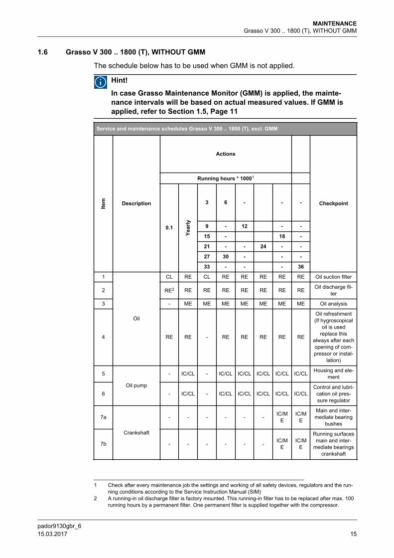
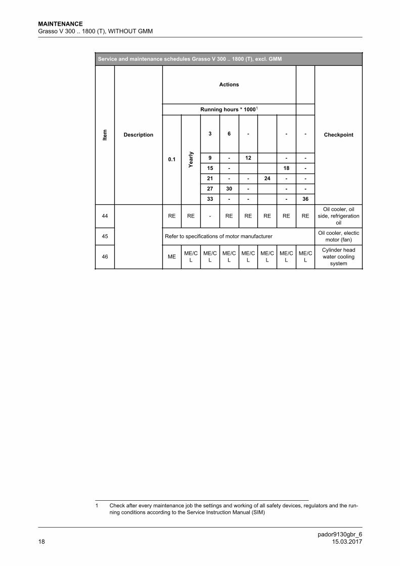
1.6 Grasso V 300 .. 1800 (T), WITHOUT GMM
The schedule below has to be used when GMM is not applied.
Hint!
In case Grasso Maintenance Monitor (GMM) is applied, the mainte-nance intervals will be based on actual measured values. If GMM isapplied, refer to Section 1.5, Page 11
Service and maintenance schedules Grasso V 300 .. 1800 (T), excl. GMM
Item Description
Actions
Checkpoint
Running hours * 10001
0.1
Year
ly
3 6 - - -
9 - 12 - -
15 - 18 -
21 - - 24 - -
27 30 - - -
33 - - - 36
1
Oil
CL RE CL RE RE RE RE RE Oil suction filter
2 RE2 RE RE RE RE RE RE RE Oil discharge fil-ter
3 - ME ME ME ME ME ME ME Oil analysis
4 RE RE - RE RE RE RE RE
Oil refreshment(If hygroscopical
oil is usedreplace this
always after eachopening of com-pressor or instal-
lation)
5
Oil pump
- IC/CL - IC/CL IC/CL IC/CL IC/CL IC/CL Housing and ele-ment
6 - IC/CL - IC/CL IC/CL IC/CL IC/CL IC/CLControl and lubri-
cation oil pres-sure regulator
7a
Crankshaft
- - - - - - IC/ME
IC/ME
Main and inter-mediate bearing
bushes
7b - - - - - - IC/ME
IC/ME
Running surfacesmain and inter-
mediate bearingscrankshaft
1 Check after every maintenance job the settings and working of all safety devices, regulators and the run-ning conditions according to the Service Instruction Manual (SIM)
2 A running-in oil discharge filter is factory mounted. This running-in filter has to be replaced after max. 100running hours by a permanent filter. One permanent filter is supplied together with the compressor.
MAINTENANCEGrasso V 300 .. 1800 (T), WITHOUT GMM
pador9130gbr_6 15.03.2017 15
Service and maintenance schedules Grasso V 300 .. 1800 (T), excl. GMM
Item Description
Actions
Checkpoint
Running hours * 10001
0.1
Year
ly
3 6 - - -
9 - 12 - -
15 - 18 -
21 - - 24 - -
27 30 - - -
33 - - - 36
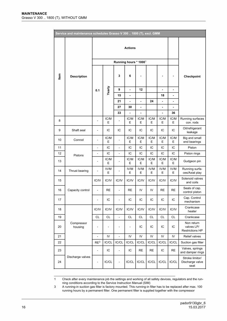
8 - IC/ME - IC/M
EIC/M
EIC/M
EIC/M
EIC/M
ERunning surfaces
con. rods
9 Shaft seal - IC IC IC IC IC IC IC Oil/refrigerantleakage
10 Conrod - IC/ME - IC/M
EIC/M
EIC/M
EIC/M
EIC/M
EBig and smallend bearings
11
Pistons
- IC - IC IC IC IC IC Piston
12 - IC - IC IC IC IC IC Piston rings
13 - IC/ME - IC/M
EIC/M
EIC/M
EIC/M
EIC/M
E Gudgeon pin
14 Thrust bearing - IV/ME - IV/M
EIV/M
EIV/M
EIV/M
EIV/M
ERunning surfa-ces/Axial play
15
Capacity control
IC/IV IC/IV IC/IV IC/IV IC/IV IC/IV IC/IV IC/IV Solenoid valvesand coils
16 - RE - RE IV IV RE RE Seals of cap.control piston
17 - IC - IC IC IC IC IC Cap. Controlmechanism
18
Compressorhousing
IC/IV IC/IV IC/IV IC/IV IC/IV IC/IV IC/IV IC/IV Crankcaseheater
19 CL CL - CL CL CL CL CL Crankcase
20 - - - - IC IC IC ICNon returnvalves LP/
Restrictions HP
21 - IV - IV IV IV IV IV Relief valves
22 RE3 IC/CL IC/CL IC/CL IC/CL IC/CL IC/CL IC/CL Suction gas filter
23
Discharge valves
- IC - IC RE RE IC RE Valves, springsand damper rings
24 - IC/CL - IC/CL IC/CL IC/CL IC/CL IC/CLStroke limitor/
Discharge valveseat
1 Check after every maintenance job the settings and working of all safety devices, regulators and the run-ning conditions according to the Service Instruction Manual (SIM)
3 A running-in suction gas filter is factory mounted. This running-in filter has to be replaced after max. 100running hours by a permanent filter. One permanent filter is supplied together with the compressor
MAINTENANCEGrasso V 300 .. 1800 (T), WITHOUT GMM
pador9130gbr_616 15.03.2017
Service and maintenance schedules Grasso V 300 .. 1800 (T), excl. GMM
Item Description
Actions
Checkpoint
Running hours * 10001
0.1
Year
ly
3 6 - - -
9 - 12 - -
15 - 18 -
21 - - 24 - -
27 30 - - -
33 - - - 36
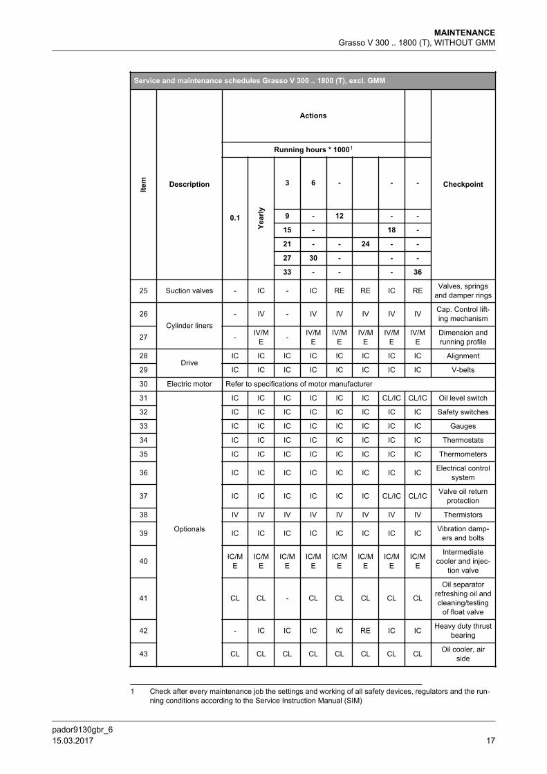
25 Suction valves - IC - IC RE RE IC RE Valves, springsand damper rings
26Cylinder liners
- IV - IV IV IV IV IV Cap. Control lift-ing mechanism
27 - IV/ME - IV/M
EIV/M
EIV/M
EIV/M
EIV/M
EDimension andrunning profile
28Drive
IC IC IC IC IC IC IC IC Alignment
29 IC IC IC IC IC IC IC IC V-belts
30 Electric motor Refer to specifications of motor manufacturer
31
Optionals
IC IC IC IC IC IC CL/IC CL/IC Oil level switch
32 IC IC IC IC IC IC IC IC Safety switches
33 IC IC IC IC IC IC IC IC Gauges
34 IC IC IC IC IC IC IC IC Thermostats
35 IC IC IC IC IC IC IC IC Thermometers
36 IC IC IC IC IC IC IC IC Electrical controlsystem
37 IC IC IC IC IC IC CL/IC CL/IC Valve oil returnprotection
38 IV IV IV IV IV IV IV IV Thermistors
39 IC IC IC IC IC IC IC IC Vibration damp-ers and bolts
40 IC/ME
IC/ME
IC/ME
IC/ME
IC/ME
IC/ME
IC/ME
IC/ME
Intermediatecooler and injec-
tion valve
41 CL CL - CL CL CL CL CL
Oil separatorrefreshing oil andcleaning/testing
of float valve
42 - IC IC IC IC RE IC IC Heavy duty thrustbearing
43 CL CL CL CL CL CL CL CL Oil cooler, airside
1 Check after every maintenance job the settings and working of all safety devices, regulators and the run-ning conditions according to the Service Instruction Manual (SIM)
MAINTENANCEGrasso V 300 .. 1800 (T), WITHOUT GMM
pador9130gbr_6 15.03.2017 17
Service and maintenance schedules Grasso V 300 .. 1800 (T), excl. GMM
Item Description
Actions
Checkpoint
Running hours * 10001
0.1
Year
ly
3 6 - - -
9 - 12 - -
15 - 18 -
21 - - 24 - -
27 30 - - -
33 - - - 36
44 RE RE - RE RE RE RE REOil cooler, oil
side, refrigerationoil
45 Refer to specifications of motor manufacturer Oil cooler, electicmotor (fan)
46 ME ME/CL
ME/CL
ME/CL
ME/CL
ME/CL
ME/CL
ME/CL
Cylinder headwater cooling
system
1 Check after every maintenance job the settings and working of all safety devices, regulators and the run-ning conditions according to the Service Instruction Manual (SIM)
MAINTENANCEGrasso V 300 .. 1800 (T), WITHOUT GMM
pador9130gbr_618 15.03.2017
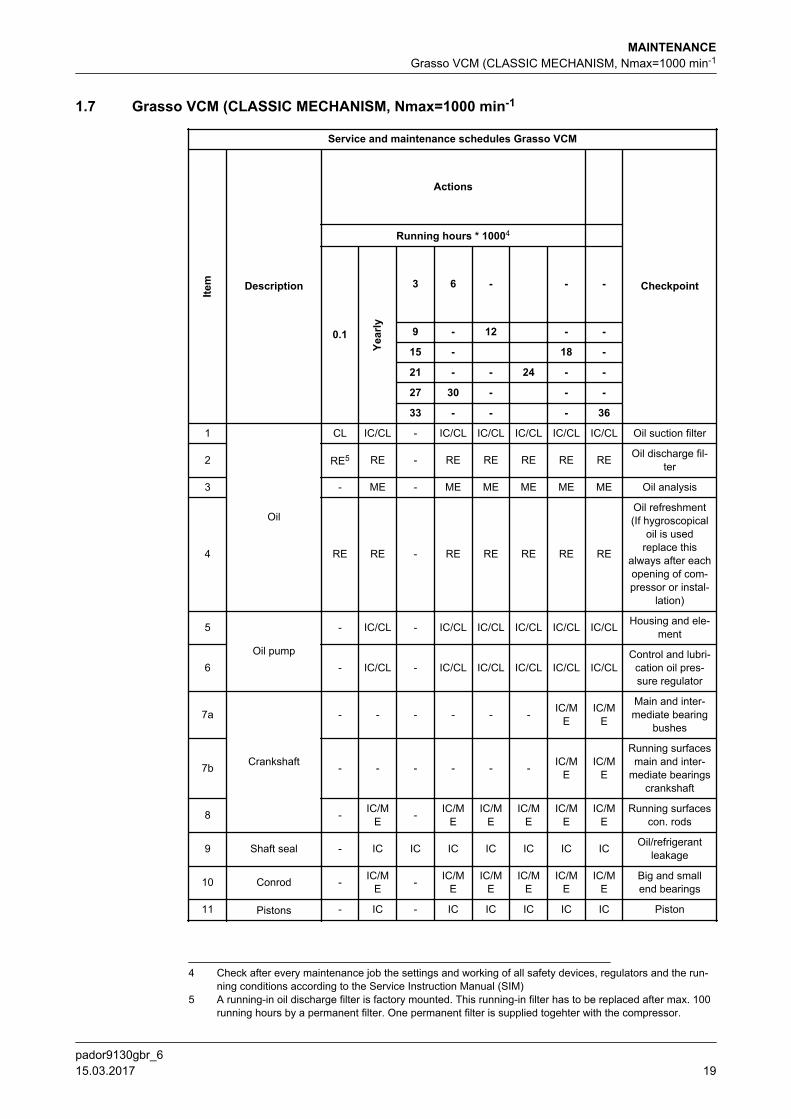
1.7 Grasso VCM (CLASSIC MECHANISM, Nmax=1000 min-1
Service and maintenance schedules Grasso VCM
Item Description
Actions
Checkpoint
Running hours * 10004
0.1
Year
ly
3 6 - - -
9 - 12 - -
15 - 18 -
21 - - 24 - -
27 30 - - -
33 - - - 36
1
Oil
CL IC/CL - IC/CL IC/CL IC/CL IC/CL IC/CL Oil suction filter
2 RE5 RE - RE RE RE RE RE Oil discharge fil-ter
3 - ME - ME ME ME ME ME Oil analysis
4 RE RE - RE RE RE RE RE
Oil refreshment(If hygroscopical
oil is usedreplace this
always after eachopening of com-pressor or instal-
lation)
5
Oil pump
- IC/CL - IC/CL IC/CL IC/CL IC/CL IC/CL Housing and ele-ment
6 - IC/CL - IC/CL IC/CL IC/CL IC/CL IC/CLControl and lubri-
cation oil pres-sure regulator
7a
Crankshaft
- - - - - - IC/ME
IC/ME
Main and inter-mediate bearing
bushes
7b - - - - - - IC/ME
IC/ME
Running surfacesmain and inter-
mediate bearingscrankshaft
8 - IC/ME - IC/M
EIC/M
EIC/M
EIC/M
EIC/M
ERunning surfaces
con. rods
9 Shaft seal - IC IC IC IC IC IC IC Oil/refrigerantleakage
10 Conrod - IC/ME - IC/M
EIC/M
EIC/M
EIC/M
EIC/M
EBig and smallend bearings
11 Pistons - IC - IC IC IC IC IC Piston
4 Check after every maintenance job the settings and working of all safety devices, regulators and the run-ning conditions according to the Service Instruction Manual (SIM)
5 A running-in oil discharge filter is factory mounted. This running-in filter has to be replaced after max. 100running hours by a permanent filter. One permanent filter is supplied togehter with the compressor.
MAINTENANCEGrasso VCM (CLASSIC MECHANISM, Nmax=1000 min-1
pador9130gbr_6 15.03.2017 19

Service and maintenance schedules Grasso VCM
Item Description
Actions
Checkpoint
Running hours * 10004
0.1
Year
ly
3 6 - - -
9 - 12 - -
15 - 18 -
21 - - 24 - -
27 30 - - -
33 - - - 36
12 - IC - IC IC IC IC IC Piston rings
13 - IC/ME - IC/M
EIC/M
EIC/M
EIC/M
EIC/M
E Gudgeon pin
14 HD thrust bearing - IC IC IC IC RE IC IC Running surfaces
15
Capacity control
IC/IV IC/IV IC/IV IC/IV IC/IV IC/IV IC/IV IC/IV Solenoid valvesand coils
16 - RE - RE IV IV RE RE Seals of cap.control piston
17 - IC - IC IC IC IC IC Cap. Controlmechanism
18
Compressorhousing
IC/IV IC/IV IC/IV IC/IV IC/IV IC/IV IC/IV IC/IV Crankcaseheater
19 CL CL - CL CL CL CL CL Crankcase
20 - - - - IC IC - ICNon returnvalves LP/
Restrictions HP
21 - IV - IV IV IV IV IV Relief valves
22 CL IC/CL - IC/CL IC/CL IC/CL IC/CL IC/CL Suction gas filter
23
Discharge valves
- IC - RE RE RE RE RE Valves, springsand damper rings
24 - IC/CL - IC/CL IC/CL IC/CL IC/CL IC/CLStroke limitor/
Discharge valveseat
25 Suction valves - IC - RE RE RE RE RE Valves, springsand damper rings
26Cylinder liners
- IV - IV IV IV IV IV Cap. Control lift-ing mechanism
27 - IV/ME - IV/M
EIV/M
EIV/M
EIV/M
EIV/M
EDimension andrunning profile
28Drive
IC IC - IC IC IC IC IC Alignment
29 IC IC IC IC IC IC IC IC V-belts
30 Electric motor Refer to specifications of motor manufacturer
4 Check after every maintenance job the settings and working of all safety devices, regulators and the run-ning conditions according to the Service Instruction Manual (SIM)
MAINTENANCEGrasso VCM (CLASSIC MECHANISM, Nmax=1000 min-1
pador9130gbr_620 15.03.2017
Service and maintenance schedules Grasso VCM
Item Description
Actions
Checkpoint
Running hours * 10004
0.1
Year
ly
3 6 - - -
9 - 12 - -
15 - 18 -
21 - - 24 - -
27 30 - - -
33 - - - 36
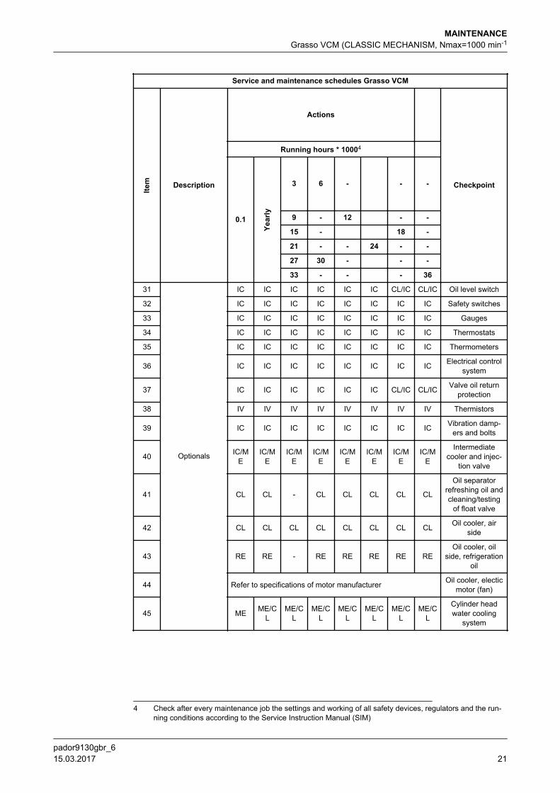
31
Optionals
IC IC IC IC IC IC CL/IC CL/IC Oil level switch
32 IC IC IC IC IC IC IC IC Safety switches
33 IC IC IC IC IC IC IC IC Gauges
34 IC IC IC IC IC IC IC IC Thermostats
35 IC IC IC IC IC IC IC IC Thermometers
36 IC IC IC IC IC IC IC IC Electrical controlsystem
37 IC IC IC IC IC IC CL/IC CL/IC Valve oil returnprotection
38 IV IV IV IV IV IV IV IV Thermistors
39 IC IC IC IC IC IC IC IC Vibration damp-ers and bolts
40 IC/ME
IC/ME
IC/ME
IC/ME
IC/ME
IC/ME
IC/ME
IC/ME
Intermediatecooler and injec-
tion valve
41 CL CL - CL CL CL CL CL
Oil separatorrefreshing oil andcleaning/testing
of float valve
42 CL CL CL CL CL CL CL CL Oil cooler, airside
43 RE RE - RE RE RE RE REOil cooler, oil
side, refrigerationoil
44 Refer to specifications of motor manufacturer Oil cooler, electicmotor (fan)
45 ME ME/CL
ME/CL
ME/CL
ME/CL
ME/CL
ME/CL
ME/CL
Cylinder headwater cooling
system
4 Check after every maintenance job the settings and working of all safety devices, regulators and the run-ning conditions according to the Service Instruction Manual (SIM)
MAINTENANCEGrasso VCM (CLASSIC MECHANISM, Nmax=1000 min-1
pador9130gbr_6 15.03.2017 21
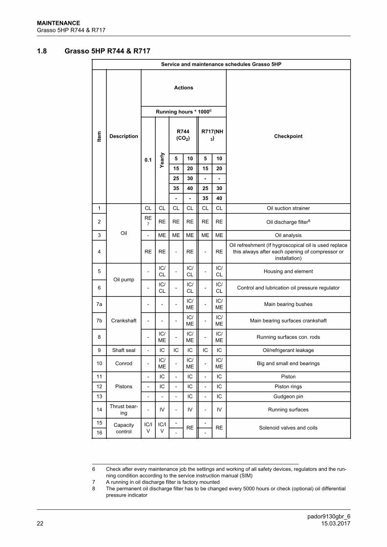
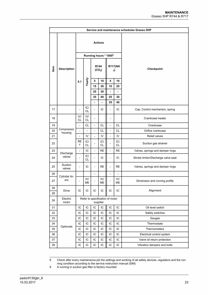
1.8 Grasso 5HP R744 & R717
Service and maintenance schedules Grasso 5HP
Item Description
Actions
Checkpoint
Running hours * 10006
0.1Ye
arly
R744(CO2)
R717(NH3)
5 10 5 10
15 20 15 20
25 30 - -
35 40 25 30
- - 35 40
1
Oil
CL CL CL CL CL CL Oil suction strainer
2RE
7 RE RE RE RE RE Oil discharge filter8
3 - ME ME ME ME ME Oil analysis
4 RE RE - RE - REOil refreshment (If hygroscopical oil is used replace
this always after each opening of compressor orinstallation)
5Oil pump
- IC/CL - IC/
CL - IC/CL Housing and element
6 - IC/CL - IC/
CL - IC/CL Control and lubrication oil pressure regulator
7a
Crankshaft
- - - IC/ME - IC/
ME Main bearing bushes
7b - - - IC/ME - IC/
ME Main bearing surfaces crankshaft
8 - IC/ME - IC/
ME - IC/ME Running surfaces con. rods
9 Shaft seal - IC IC IC IC IC Oil/refrigerant leakage
10 Conrod - IC/ME - IC/
ME - IC/ME Big and small end bearings
11
Pistons
- IC - IC - IC Piston
12 - IC - IC - IC Piston rings
13 - - - IC - IC Gudgeon pin
14 Thrust bear-ing - IV - IV - IV Running surfaces
15 Capacitycontrol
IC/IV
IC/IV
-RE
-RE Solenoid valves and coils
16 - -
6 Check after every maintenance job the settings and working of all safety devices, regulators and the run-ning condition according to the service instruction manual (SIM)
7 A running in oil discharge filter is factory mounted8 The permanent oil discharge filter has to be changed every 5000 hours or check (optional) oil differential
pressure indicator
MAINTENANCEGrasso 5HP R744 & R717
pador9130gbr_622 15.03.2017
Service and maintenance schedules Grasso 5HP
Item Description
Actions
Checkpoint
Running hours * 10006
0.1
Year
ly
R744(CO2)
R717(NH3)
5 10 5 10
15 20 15 20
25 30 - -
35 40 25 30
- - 35 40
17 - IC/CL - IC - IC Cap. Control mechanism, spring
18
Compressorhousing
IV/CL
IV/CL - - Crankcase heater
19 - CL - CL - CL Crankcase
20 - - - CL - CL Orifice crankcase
21 - IV - IV - IV Relief valves
22RE
9IC/CL - IC/
CL - IC/CL Suction gas strainer
23Discharge
valves
- IC - RE - RE Valves, springs and damper rings
24 - IC/CL - IC - IC Stroke limitor/Discharge valve seat
25 Suctionvalves - IC - RE - RE Valves, springs and damper rings
26Cylinder lin-
ers
- - -
27 - IV/ME - IV/
ME - IV/ME Dimension and running profile
28Drive IC IC IC IC IC IC Alignment
29
30 Electricmotor
Refer to specification of motorsupplier
31
Optionals
IC IC IC IC IC IC Oil level switch
32 IC IC IC IC IC IC Safety switches
33 IC IC IC IC IC IC Gauges
34 IC IC IC IC IC IC Thermostats
35 IC IC IC IC IC IC Thermometers
36 IC IC IC IC IC IC Electrical control system
37 IC IC IC IC IC IC Valve oil return protection
39 IC IC IC IC IC IC Vibration dampers and bolts
6 Check after every maintenance job the settings and working of all safety devices, regulators and the run-ning condition according to the service instruction manual (SIM)
9 A running in suction gas filter is factory mounted
MAINTENANCEGrasso 5HP R744 & R717
pador9130gbr_6 15.03.2017 23
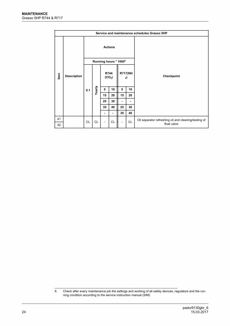
Service and maintenance schedules Grasso 5HP
Item Description
Actions
Checkpoint
Running hours * 10006
0.1
Year
ly
R744(CO2)
R717(NH3)
5 10 5 10
15 20 15 20
25 30 - -
35 40 25 30
- - 35 40
41CL CL - CL - CL Oil separator refreshing oil and cleaning/testing of
float valve42
6 Check after every maintenance job the settings and working of all safety devices, regulators and the run-ning condition according to the service instruction manual (SIM)
MAINTENANCEGrasso 5HP R744 & R717
pador9130gbr_624 15.03.2017
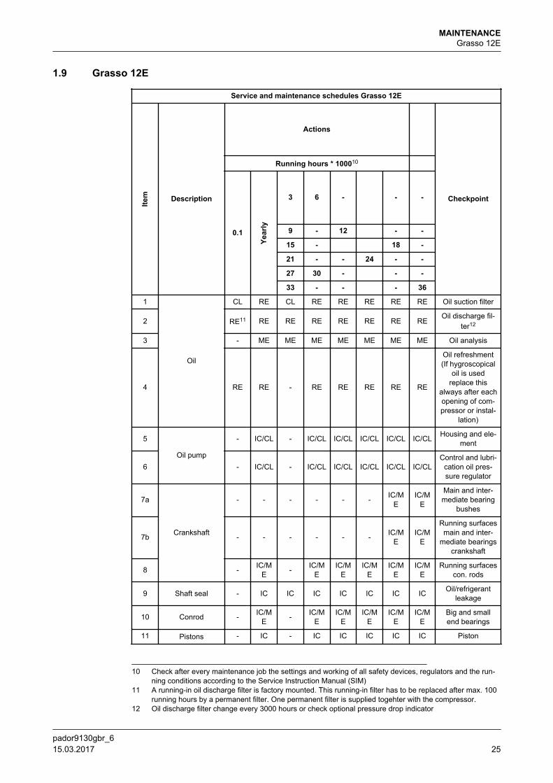
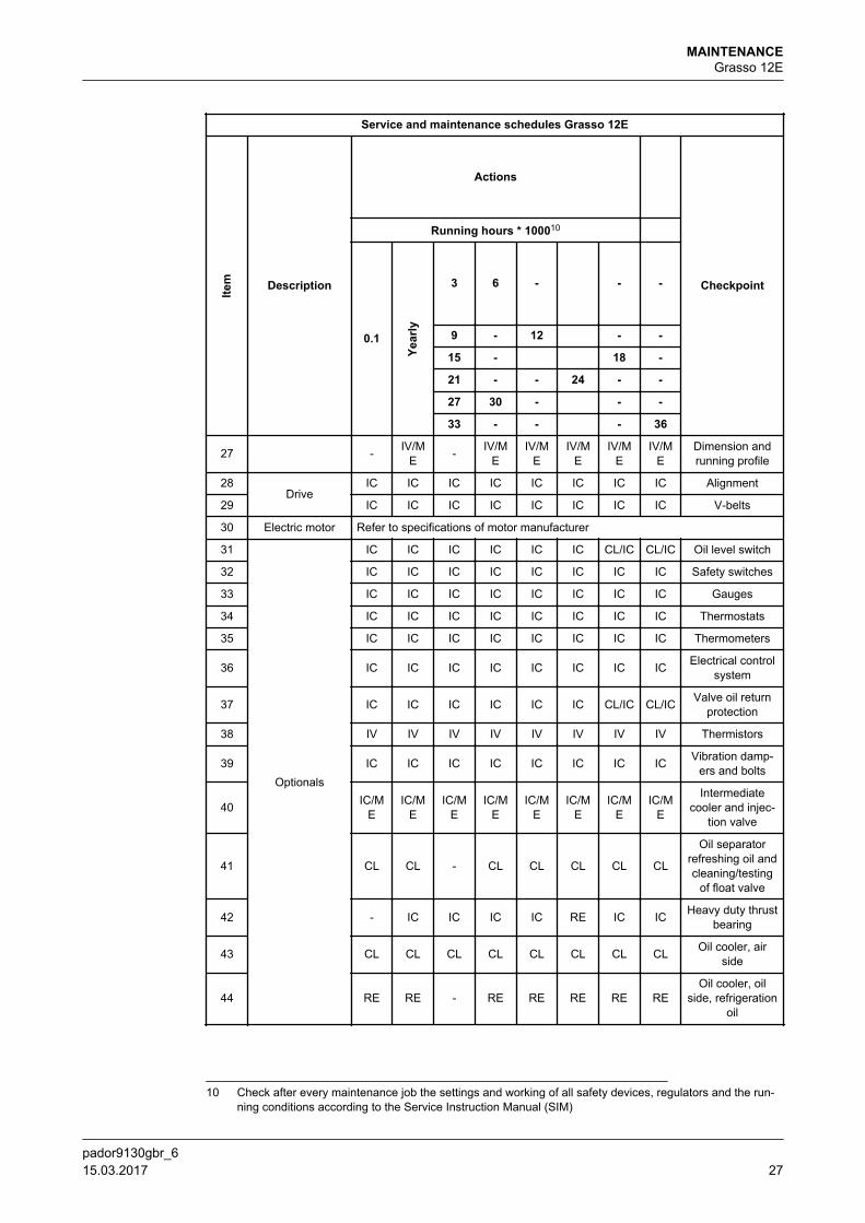
1.9 Grasso 12E
Service and maintenance schedules Grasso 12E
Item Description
Actions
Checkpoint
Running hours * 100010
0.1
Year
ly
3 6 - - -
9 - 12 - -
15 - 18 -
21 - - 24 - -
27 30 - - -
33 - - - 36
1
Oil
CL RE CL RE RE RE RE RE Oil suction filter
2 RE11 RE RE RE RE RE RE REOil discharge fil-
ter12
3 - ME ME ME ME ME ME ME Oil analysis
4 RE RE - RE RE RE RE RE
Oil refreshment(If hygroscopical
oil is usedreplace this
always after eachopening of com-pressor or instal-
lation)
5
Oil pump
- IC/CL - IC/CL IC/CL IC/CL IC/CL IC/CL Housing and ele-ment
6 - IC/CL - IC/CL IC/CL IC/CL IC/CL IC/CLControl and lubri-
cation oil pres-sure regulator
7a
Crankshaft
- - - - - - IC/ME
IC/ME
Main and inter-mediate bearing
bushes
7b - - - - - - IC/ME
IC/ME
Running surfacesmain and inter-
mediate bearingscrankshaft
8 - IC/ME - IC/M
EIC/M
EIC/M
EIC/M
EIC/M
ERunning surfaces
con. rods
9 Shaft seal - IC IC IC IC IC IC IC Oil/refrigerantleakage
10 Conrod - IC/ME - IC/M
EIC/M
EIC/M
EIC/M
EIC/M
EBig and smallend bearings
11 Pistons - IC - IC IC IC IC IC Piston
10 Check after every maintenance job the settings and working of all safety devices, regulators and the run-ning conditions according to the Service Instruction Manual (SIM)
11 A running-in oil discharge filter is factory mounted. This running-in filter has to be replaced after max. 100running hours by a permanent filter. One permanent filter is supplied togehter with the compressor.
12 Oil discharge filter change every 3000 hours or check optional pressure drop indicator
MAINTENANCEGrasso 12E
pador9130gbr_6 15.03.2017 25
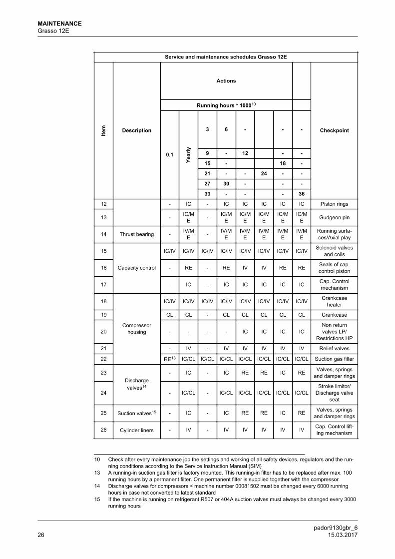
Service and maintenance schedules Grasso 12E
Item Description
Actions
Checkpoint
Running hours * 100010
0.1
Year
ly
3 6 - - -
9 - 12 - -
15 - 18 -
21 - - 24 - -
27 30 - - -
33 - - - 36
12 - IC - IC IC IC IC IC Piston rings
13 - IC/ME - IC/M
EIC/M
EIC/M
EIC/M
EIC/M
E Gudgeon pin
14 Thrust bearing - IV/ME - IV/M
EIV/M
EIV/M
EIV/M
EIV/M
ERunning surfa-ces/Axial play
15
Capacity control
IC/IV IC/IV IC/IV IC/IV IC/IV IC/IV IC/IV IC/IV Solenoid valvesand coils
16 - RE - RE IV IV RE RE Seals of cap.control piston
17 - IC - IC IC IC IC IC Cap. Controlmechanism
18
Compressorhousing
IC/IV IC/IV IC/IV IC/IV IC/IV IC/IV IC/IV IC/IV Crankcaseheater
19 CL CL - CL CL CL CL CL Crankcase
20 - - - - IC IC IC ICNon returnvalves LP/
Restrictions HP
21 - IV - IV IV IV IV IV Relief valves
22 RE13 IC/CL IC/CL IC/CL IC/CL IC/CL IC/CL IC/CL Suction gas filter
23Dischargevalves14
- IC - IC RE RE IC RE Valves, springsand damper rings
24 - IC/CL - IC/CL IC/CL IC/CL IC/CL IC/CLStroke limitor/
Discharge valveseat
25 Suction valves15 - IC - IC RE RE IC RE Valves, springsand damper rings
26 Cylinder liners - IV - IV IV IV IV IV Cap. Control lift-ing mechanism
10 Check after every maintenance job the settings and working of all safety devices, regulators and the run-ning conditions according to the Service Instruction Manual (SIM)
13 A running-in suction gas filter is factory mounted. This running-in filter has to be replaced after max. 100running hours by a permanent filter. One permanent filter is supplied together with the compressor
14 Discharge valves for compressors < machine number 00081502 must be changed every 6000 runninghours in case not converted to latest standard
15 If the machine is running on refrigerant R507 or 404A suction valves must always be changed every 3000running hours
MAINTENANCEGrasso 12E
pador9130gbr_626 15.03.2017
Service and maintenance schedules Grasso 12E
Item Description
Actions
Checkpoint
Running hours * 100010
0.1
Year
ly
3 6 - - -
9 - 12 - -
15 - 18 -
21 - - 24 - -
27 30 - - -
33 - - - 36
27 - IV/ME - IV/M
EIV/M
EIV/M
EIV/M
EIV/M
EDimension andrunning profile
28Drive
IC IC IC IC IC IC IC IC Alignment
29 IC IC IC IC IC IC IC IC V-belts
30 Electric motor Refer to specifications of motor manufacturer
31
Optionals
IC IC IC IC IC IC CL/IC CL/IC Oil level switch
32 IC IC IC IC IC IC IC IC Safety switches
33 IC IC IC IC IC IC IC IC Gauges
34 IC IC IC IC IC IC IC IC Thermostats
35 IC IC IC IC IC IC IC IC Thermometers
36 IC IC IC IC IC IC IC IC Electrical controlsystem
37 IC IC IC IC IC IC CL/IC CL/IC Valve oil returnprotection
38 IV IV IV IV IV IV IV IV Thermistors
39 IC IC IC IC IC IC IC IC Vibration damp-ers and bolts
40 IC/ME
IC/ME
IC/ME
IC/ME
IC/ME
IC/ME
IC/ME
IC/ME
Intermediatecooler and injec-
tion valve
41 CL CL - CL CL CL CL CL
Oil separatorrefreshing oil andcleaning/testing
of float valve
42 - IC IC IC IC RE IC IC Heavy duty thrustbearing
43 CL CL CL CL CL CL CL CL Oil cooler, airside
44 RE RE - RE RE RE RE REOil cooler, oil
side, refrigerationoil
10 Check after every maintenance job the settings and working of all safety devices, regulators and the run-ning conditions according to the Service Instruction Manual (SIM)
MAINTENANCEGrasso 12E
pador9130gbr_6 15.03.2017 27
Service and maintenance schedules Grasso 12E
Item Description
Actions
Checkpoint
Running hours * 100010
0.1
Year
ly
3 6 - - -
9 - 12 - -
15 - 18 -
21 - - 24 - -
27 30 - - -
33 - - - 36
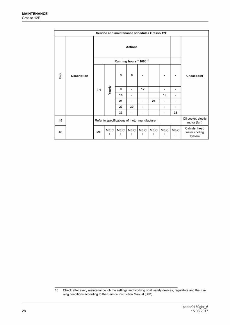
45 Refer to specifications of motor manufacturer Oil cooler, electicmotor (fan)
46 ME ME/CL
ME/CL
ME/CL
ME/CL
ME/CL
ME/CL
ME/CL
Cylinder headwater cooling
system
10 Check after every maintenance job the settings and working of all safety devices, regulators and the run-ning conditions according to the Service Instruction Manual (SIM)
MAINTENANCEGrasso 12E
pador9130gbr_628 15.03.2017

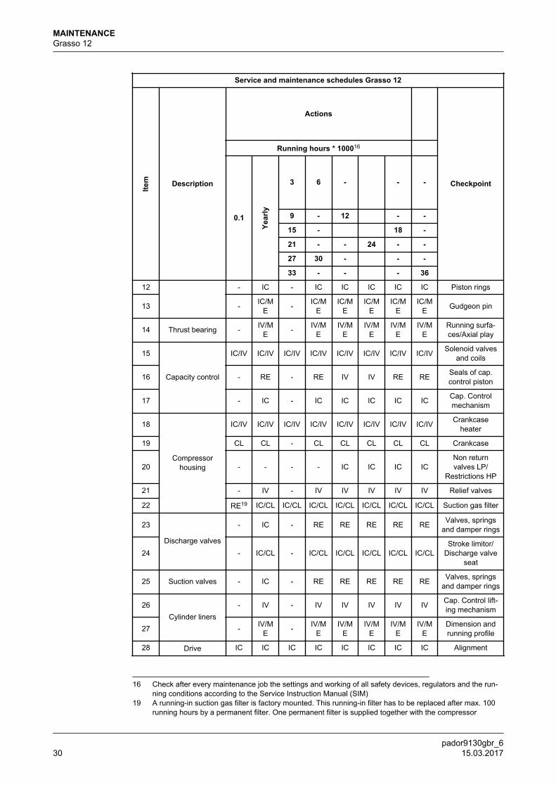
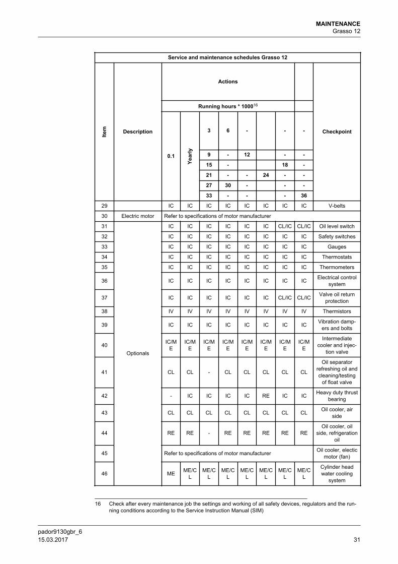
1.10 Grasso 12
Service and maintenance schedules Grasso 12
Item Description
Actions
Checkpoint
Running hours * 100016
0.1
Year
ly
3 6 - - -
9 - 12 - -
15 - 18 -
21 - - 24 - -
27 30 - - -
33 - - - 36
1
Oil
CL RE CL RE RE RE RE RE Oil suction filter
2 RE17 RE RE RE RE RE RE REOil discharge fil-
ter18
3 - ME ME ME ME ME ME ME Oil analysis
4 RE RE - RE RE RE RE RE
Oil refreshment(If hygroscopical
oil is usedreplace this
always after eachopening of com-pressor or instal-
lation)
5
Oil pump
- IC/CL - IC/CL IC/CL IC/CL IC/CL IC/CL Housing and ele-ment
6 - IC/CL - IC/CL IC/CL IC/CL IC/CL IC/CLControl and lubri-
cation oil pres-sure regulator
7a
Crankshaft
- - - - - - IC/ME
IC/ME
Main and inter-mediate bearing
bushes
7b - - - - - - IC/ME
IC/ME
Running surfacesmain and inter-
mediate bearingscrankshaft
8 - IC/ME - IC/M
EIC/M
EIC/M
EIC/M
EIC/M
ERunning surfaces
con. rods
9 Shaft seal - IC IC IC IC IC IC IC Oil/refrigerantleakage
10 Conrod - IC/ME - IC/M
EIC/M
EIC/M
EIC/M
EIC/M
EBig and smallend bearings
11 Pistons - IC - IC IC IC IC IC Piston
16 Check after every maintenance job the settings and working of all safety devices, regulators and the run-ning conditions according to the Service Instruction Manual (SIM)
17 A running-in oil discharge filter is factory mounted. This running-in filter has to be replaced after max. 100running hours by a permanent filter. One permanent filter is supplied togehter with the compressor.
18 Oil discharge filter change every 3000 hours or check optional pressure drop indicator
MAINTENANCEGrasso 12
pador9130gbr_6 15.03.2017 29
Service and maintenance schedules Grasso 12
Item Description
Actions
Checkpoint
Running hours * 100016
0.1
Year
ly
3 6 - - -
9 - 12 - -
15 - 18 -
21 - - 24 - -
27 30 - - -
33 - - - 36
12 - IC - IC IC IC IC IC Piston rings
13 - IC/ME - IC/M
EIC/M
EIC/M
EIC/M
EIC/M
E Gudgeon pin
14 Thrust bearing - IV/ME - IV/M
EIV/M
EIV/M
EIV/M
EIV/M
ERunning surfa-ces/Axial play
15
Capacity control
IC/IV IC/IV IC/IV IC/IV IC/IV IC/IV IC/IV IC/IV Solenoid valvesand coils
16 - RE - RE IV IV RE RE Seals of cap.control piston
17 - IC - IC IC IC IC IC Cap. Controlmechanism
18
Compressorhousing
IC/IV IC/IV IC/IV IC/IV IC/IV IC/IV IC/IV IC/IV Crankcaseheater
19 CL CL - CL CL CL CL CL Crankcase
20 - - - - IC IC IC ICNon returnvalves LP/
Restrictions HP
21 - IV - IV IV IV IV IV Relief valves
22 RE19 IC/CL IC/CL IC/CL IC/CL IC/CL IC/CL IC/CL Suction gas filter
23
Discharge valves
- IC - RE RE RE RE RE Valves, springsand damper rings
24 - IC/CL - IC/CL IC/CL IC/CL IC/CL IC/CLStroke limitor/
Discharge valveseat
25 Suction valves - IC - RE RE RE RE RE Valves, springsand damper rings
26Cylinder liners
- IV - IV IV IV IV IV Cap. Control lift-ing mechanism
27 - IV/ME - IV/M
EIV/M
EIV/M
EIV/M
EIV/M
EDimension andrunning profile
28 Drive IC IC IC IC IC IC IC IC Alignment
16 Check after every maintenance job the settings and working of all safety devices, regulators and the run-ning conditions according to the Service Instruction Manual (SIM)
19 A running-in suction gas filter is factory mounted. This running-in filter has to be replaced after max. 100running hours by a permanent filter. One permanent filter is supplied together with the compressor
MAINTENANCEGrasso 12
pador9130gbr_630 15.03.2017
Service and maintenance schedules Grasso 12
Item Description
Actions
Checkpoint
Running hours * 100016
0.1
Year
ly
3 6 - - -
9 - 12 - -
15 - 18 -
21 - - 24 - -
27 30 - - -
33 - - - 36
29 IC IC IC IC IC IC IC IC V-belts
30 Electric motor Refer to specifications of motor manufacturer
31
Optionals
IC IC IC IC IC IC CL/IC CL/IC Oil level switch
32 IC IC IC IC IC IC IC IC Safety switches
33 IC IC IC IC IC IC IC IC Gauges
34 IC IC IC IC IC IC IC IC Thermostats
35 IC IC IC IC IC IC IC IC Thermometers
36 IC IC IC IC IC IC IC IC Electrical controlsystem
37 IC IC IC IC IC IC CL/IC CL/IC Valve oil returnprotection
38 IV IV IV IV IV IV IV IV Thermistors
39 IC IC IC IC IC IC IC IC Vibration damp-ers and bolts
40 IC/ME
IC/ME
IC/ME
IC/ME
IC/ME
IC/ME
IC/ME
IC/ME
Intermediatecooler and injec-
tion valve
41 CL CL - CL CL CL CL CL
Oil separatorrefreshing oil andcleaning/testing
of float valve
42 - IC IC IC IC RE IC IC Heavy duty thrustbearing
43 CL CL CL CL CL CL CL CL Oil cooler, airside
44 RE RE - RE RE RE RE REOil cooler, oil
side, refrigerationoil
45 Refer to specifications of motor manufacturer Oil cooler, electicmotor (fan)
46 ME ME/CL
ME/CL
ME/CL
ME/CL
ME/CL
ME/CL
ME/CL
Cylinder headwater cooling
system
16 Check after every maintenance job the settings and working of all safety devices, regulators and the run-ning conditions according to the Service Instruction Manual (SIM)
MAINTENANCEGrasso 12
pador9130gbr_6 15.03.2017 31
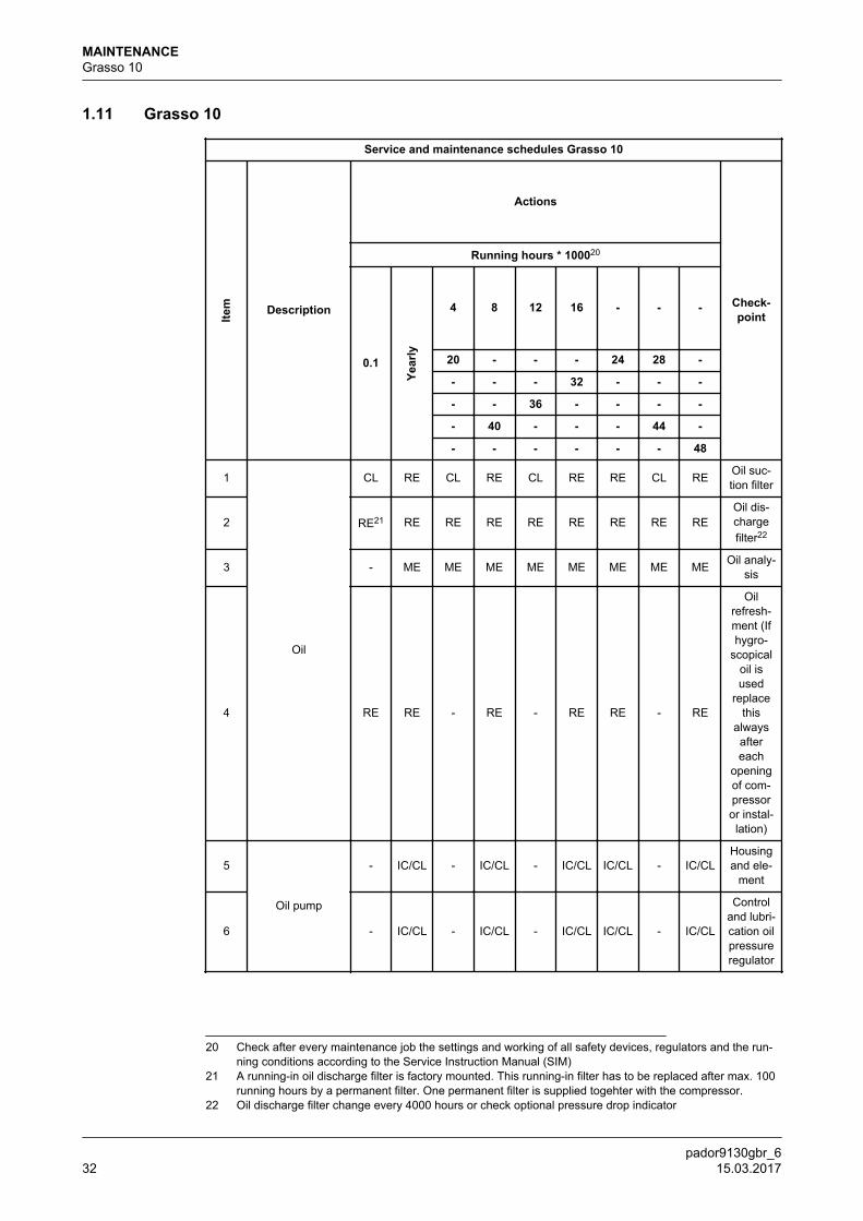
1.11 Grasso 10
Service and maintenance schedules Grasso 10
Item Description
Actions
Check-point
Running hours * 100020
0.1
Year
ly
4 8 12 16 - - -
20 - - - 24 28 -
- - - 32 - - -
- - 36 - - - -
- 40 - - - 44 -
- - - - - - 48
1
Oil
CL RE CL RE CL RE RE CL RE Oil suc-tion filter
2 RE21 RE RE RE RE RE RE RE REOil dis-chargefilter22
3 - ME ME ME ME ME ME ME ME Oil analy-sis
4 RE RE - RE - RE RE - RE
Oilrefresh-ment (Ifhygro-
scopicaloil isused
replacethis
alwaysaftereach
openingof com-pressoror instal-lation)
5
Oil pump
- IC/CL - IC/CL - IC/CL IC/CL - IC/CLHousingand ele-
ment
6 - IC/CL - IC/CL - IC/CL IC/CL - IC/CL
Controland lubri-cation oilpressureregulator
20 Check after every maintenance job the settings and working of all safety devices, regulators and the run-ning conditions according to the Service Instruction Manual (SIM)
21 A running-in oil discharge filter is factory mounted. This running-in filter has to be replaced after max. 100running hours by a permanent filter. One permanent filter is supplied togehter with the compressor.
22 Oil discharge filter change every 4000 hours or check optional pressure drop indicator
MAINTENANCEGrasso 10
pador9130gbr_632 15.03.2017
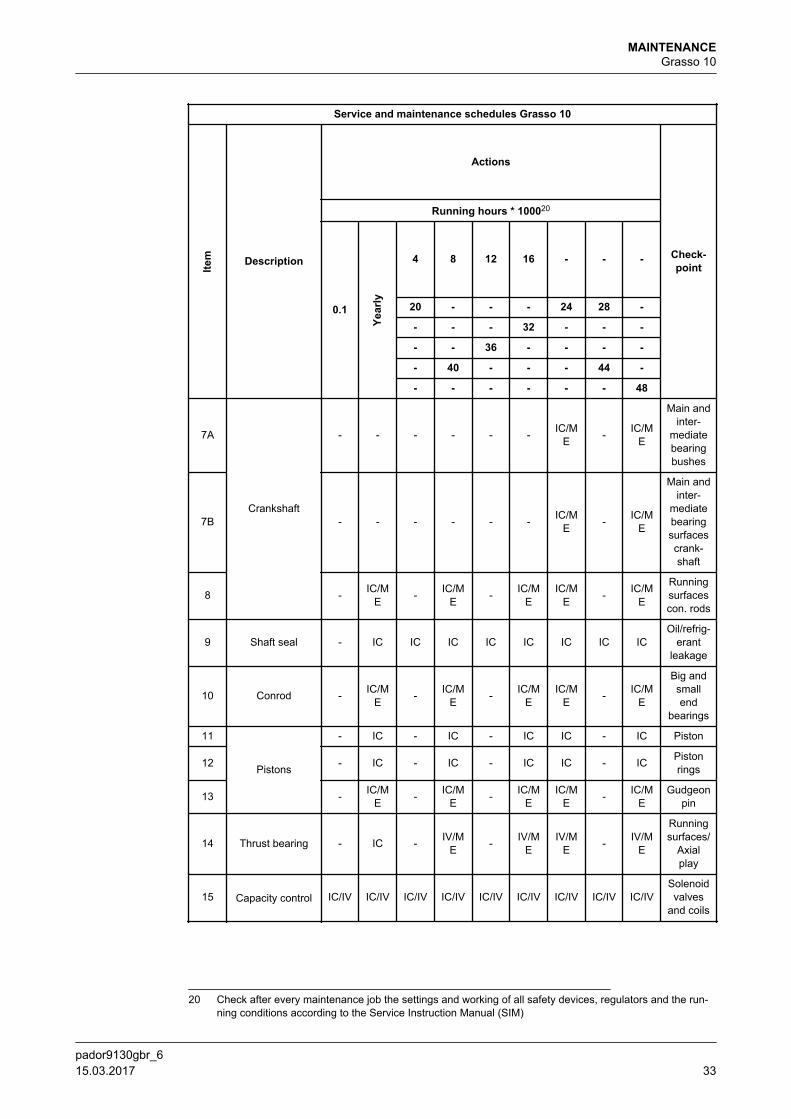
Service and maintenance schedules Grasso 10
Item Description
Actions
Check-point
Running hours * 100020
0.1
Year
ly
4 8 12 16 - - -
20 - - - 24 28 -
- - - 32 - - -
- - 36 - - - -
- 40 - - - 44 -
- - - - - - 48
7A
Crankshaft
- - - - - - IC/ME - IC/M
E
Main andinter-
mediatebearingbushes
7B - - - - - - IC/ME - IC/M
E
Main andinter-
mediatebearingsurfacescrank-shaft
8 - IC/ME - IC/M
E - IC/ME
IC/ME - IC/M
E
Runningsurfacescon. rods
9 Shaft seal - IC IC IC IC IC IC IC ICOil/refrig-
erantleakage
10 Conrod - IC/ME - IC/M
E - IC/ME
IC/ME - IC/M
E
Big andsmallend
bearings
11
Pistons
- IC - IC - IC IC - IC Piston
12 - IC - IC - IC IC - IC Pistonrings
13 - IC/ME - IC/M
E - IC/ME
IC/ME - IC/M
EGudgeon
pin
14 Thrust bearing - IC - IV/ME - IV/M
EIV/M
E - IV/ME
Runningsurfaces/
Axialplay
15 Capacity control IC/IV IC/IV IC/IV IC/IV IC/IV IC/IV IC/IV IC/IV IC/IVSolenoidvalves
and coils
20 Check after every maintenance job the settings and working of all safety devices, regulators and the run-ning conditions according to the Service Instruction Manual (SIM)
MAINTENANCEGrasso 10
pador9130gbr_6 15.03.2017 33
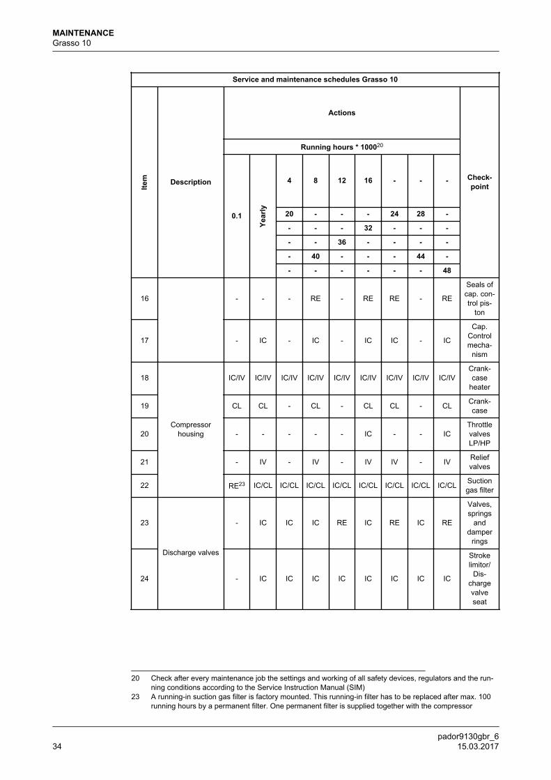
Service and maintenance schedules Grasso 10
Item Description
Actions
Check-point
Running hours * 100020
0.1
Year
ly
4 8 12 16 - - -
20 - - - 24 28 -
- - - 32 - - -
- - 36 - - - -
- 40 - - - 44 -
- - - - - - 48
16 - - - RE - RE RE - RE
Seals ofcap. con-trol pis-
ton
17 - IC - IC - IC IC - IC
Cap.Controlmecha-
nism
18
Compressorhousing
IC/IV IC/IV IC/IV IC/IV IC/IV IC/IV IC/IV IC/IV IC/IVCrank-case
heater
19 CL CL - CL - CL CL - CL Crank-case
20 - - - - - IC - - ICThrottlevalvesLP/HP
21 - IV - IV - IV IV - IV Reliefvalves
22 RE23 IC/CL IC/CL IC/CL IC/CL IC/CL IC/CL IC/CL IC/CL Suctiongas filter
23
Discharge valves
- IC IC IC RE IC RE IC RE
Valves,springs
anddamper
rings
24 - IC IC IC IC IC IC IC IC
Strokelimitor/
Dis-chargevalveseat
20 Check after every maintenance job the settings and working of all safety devices, regulators and the run-ning conditions according to the Service Instruction Manual (SIM)
23 A running-in suction gas filter is factory mounted. This running-in filter has to be replaced after max. 100running hours by a permanent filter. One permanent filter is supplied together with the compressor
MAINTENANCEGrasso 10
pador9130gbr_634 15.03.2017
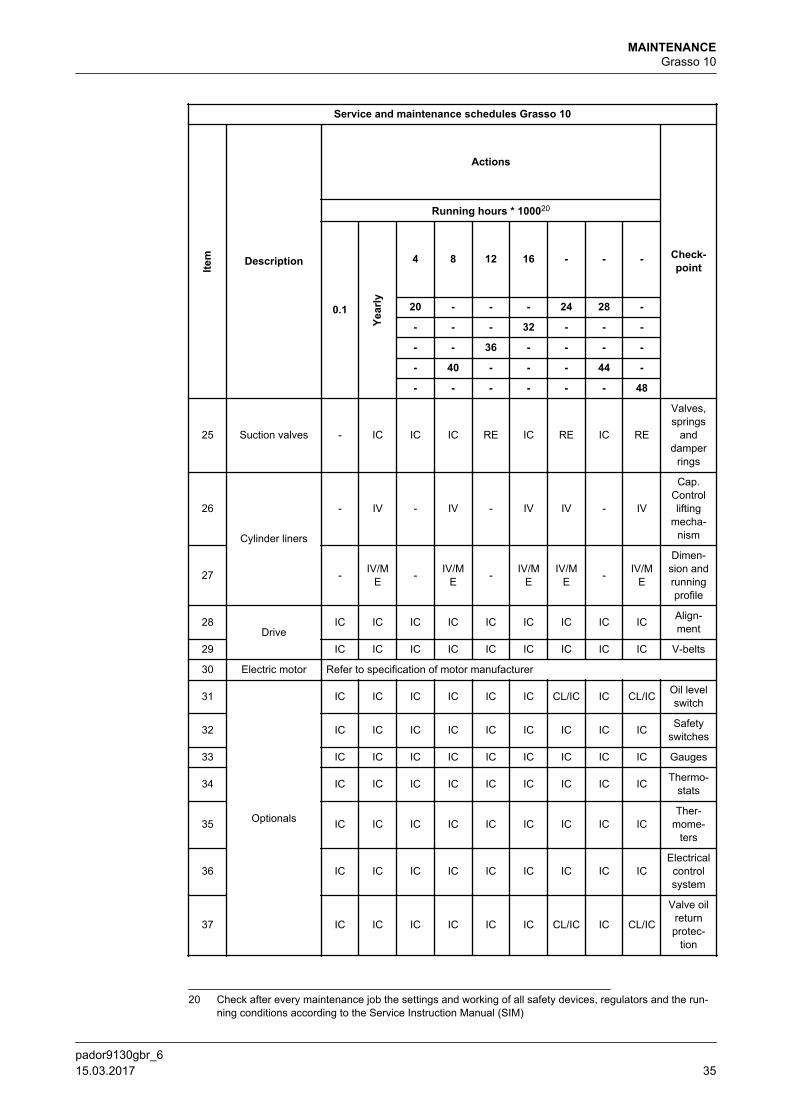
Service and maintenance schedules Grasso 10
Item Description
Actions
Check-point
Running hours * 100020
0.1
Year
ly
4 8 12 16 - - -
20 - - - 24 28 -
- - - 32 - - -
- - 36 - - - -
- 40 - - - 44 -
- - - - - - 48
25 Suction valves - IC IC IC RE IC RE IC RE
Valves,springs
anddamper
rings
26
Cylinder liners
- IV - IV - IV IV - IV
Cap.Controllifting
mecha-nism
27 - IV/ME - IV/M
E - IV/ME
IV/ME - IV/M
E
Dimen-sion andrunningprofile
28Drive
IC IC IC IC IC IC IC IC IC Align-ment
29 IC IC IC IC IC IC IC IC IC V-belts
30 Electric motor Refer to specification of motor manufacturer
31
Optionals
IC IC IC IC IC IC CL/IC IC CL/IC Oil levelswitch
32 IC IC IC IC IC IC IC IC IC Safetyswitches
33 IC IC IC IC IC IC IC IC IC Gauges
34 IC IC IC IC IC IC IC IC IC Thermo-stats
35 IC IC IC IC IC IC IC IC ICTher-
mome-ters
36 IC IC IC IC IC IC IC IC ICElectricalcontrolsystem
37 IC IC IC IC IC IC CL/IC IC CL/IC
Valve oilreturnprotec-
tion
20 Check after every maintenance job the settings and working of all safety devices, regulators and the run-ning conditions according to the Service Instruction Manual (SIM)
MAINTENANCEGrasso 10
pador9130gbr_6 15.03.2017 35
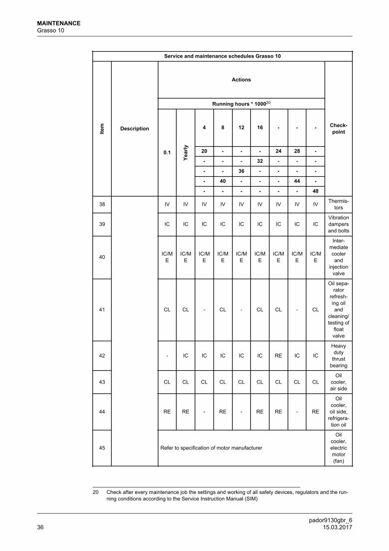
Service and maintenance schedules Grasso 10
Item Description
Actions
Check-point
Running hours * 100020
0.1
Year
ly
4 8 12 16 - - -
20 - - - 24 28 -
- - - 32 - - -
- - 36 - - - -
- 40 - - - 44 -
- - - - - - 48
38 IV IV IV IV IV IV IV IV IV Thermis-tors
39 IC IC IC IC IC IC IC IC ICVibrationdampersand bolts
40 IC/ME
IC/ME
IC/ME
IC/ME
IC/ME
IC/ME
IC/ME
IC/ME
IC/ME
Inter-mediatecoolerand
injectionvalve
41 CL CL - CL - CL CL - CL
Oil sepa-rator
refresh-ing oiland
cleaning/testing of
floatvalve
42 - IC IC IC IC IC RE IC IC
Heavyduty
thrustbearing
43 CL CL CL CL CL CL CL CL CLOil
cooler,air side
44 RE RE - RE - RE RE - RE
Oilcooler,oil side,
refrigera-tion oil
45 Refer to specification of motor manufacturer
Oilcooler,electricmotor(fan)
20 Check after every maintenance job the settings and working of all safety devices, regulators and the run-ning conditions according to the Service Instruction Manual (SIM)
MAINTENANCEGrasso 10
pador9130gbr_636 15.03.2017
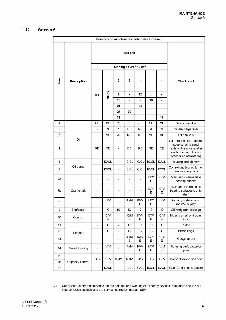
1.12 Grasso 6
Service and maintenance schedules Grasso 6
Item Description
Actions
Checkpoint
Running hours * 100024
0.1
Year
ly
3 6 - - -
9 - 12 - -
15 - - 18 -
21 - 24 - -
27 30 - - -
33 - - - 36
1
Oil
CL CL CL CL CL CL CL Oil suction filter
2 - RE RE RE RE RE RE Oil discharge filter
3 - ME ME ME ME ME ME Oil analysis
4 RE RE - RE RE RE RE
Oil refreshment (If hygro-scopical oil is used
replace this always aftereach opening of com-pressor or installation)
5Oil pump
- IC/CL - IC/CL IC/CL IC/CL IC/CL Housing and element
6 - IC/CL - IC/CL IC/CL IC/CL IC/CL Control and lubrication oilpressure regulator
7a
Crankshaft
- - - - - IC/ME
IC/ME
Main and intermediatebearing bushes
7b - - - - - IC/ME
IC/ME
Main and intermediatebearing surfaces crank-
shaft
8 - IC/ME - IC/M
EIC/M
EIC/M
EIC/M
ERunning surfaces con.
rods/Axial play
9 Shaft seal - IC IC IC IC IC IC Oil/refrigerant leakage
10 Conrod - IC/ME - IC/M
EIC/M
EIC/M
EIC/M
EBig and small end bear-
ings
11
Pistons
- IC - IC IC IC IC Piston
12 - IC - IC IC IC IC Piston rings
13 - - - IC/ME
IC/ME
IC/ME
IC/ME Gudgeon pin
14 Thrust bearing - IV/ME - IV/M
EIV/M
EIV/M
EIV/M
ERunning surfaces/axial
play
15
Capacity controlIC/IV IC/IV IC/IV IC/IV IC/IV IC/IV IC/IV Solenoid valves and coils
16
17 - IC/CL - IC/CL IC/CL IC/CL IC/CL Cap. Control mechanism
24 Check after every maintenance job the settings and working of all safety devices, regulators and the run-ning condition according to the service instruction manual (SIM)
MAINTENANCEGrasso 6
pador9130gbr_6 15.03.2017 37
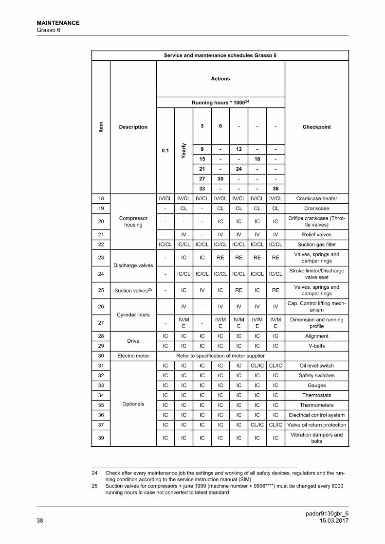
Service and maintenance schedules Grasso 6
Item Description
Actions
Checkpoint
Running hours * 100024
0.1
Year
ly
3 6 - - -
9 - 12 - -
15 - - 18 -
21 - 24 - -
27 30 - - -
33 - - - 36
18
Compressorhousing
IV/CL IV/CL IV/CL IV/CL IV/CL IV/CL IV/CL Crankcase heater
19 - CL - CL CL CL CL Crankcase
20 - - - IC IC IC IC Orifice crankcase (Throt-tle valves)
21 - IV - IV IV IV IV Relief valves
22 IC/CL IC/CL IC/CL IC/CL IC/CL IC/CL IC/CL Suction gas filter
23Discharge valves
- IC IC RE RE RE RE Valves, springs anddamper rings
24 - IC/CL IC/CL IC/CL IC/CL IC/CL IC/CL Stroke limitor/Dischargevalve seat
25 Suction valves25 - IC IV IC RE IC RE Valves, springs anddamper rings
26Cylinder liners
- IV - IV IV IV IV Cap. Control lifting mech-anism
27 - IV/ME - IV/M
EIV/M
EIV/M
EIV/M
EDimension and running
profile
28Drive
IC IC IC IC IC IC IC Alignment
29 IC IC IC IC IC IC IC V-belts
30 Electric motor Refer to specification of motor supplier 31
Optionals
IC IC IC IC IC CL/IC CL/IC Oil level switch
32 IC IC IC IC IC IC IC Safety switches
33 IC IC IC IC IC IC IC Gauges
34 IC IC IC IC IC IC IC Thermostats
35 IC IC IC IC IC IC IC Thermometers
36 IC IC IC IC IC IC IC Electrical control system
37 IC IC IC IC IC CL/IC CL/IC Valve oil return protection
39 IC IC IC IC IC IC IC Vibration dampers andbolts
24 Check after every maintenance job the settings and working of all safety devices, regulators and the run-ning condition according to the service instruction manual (SIM)
25 Suction valves for compressors < june 1999 (machine number < 9906****) must be changed every 6000running hours in case not converted to latest standard
MAINTENANCEGrasso 6
pador9130gbr_638 15.03.2017
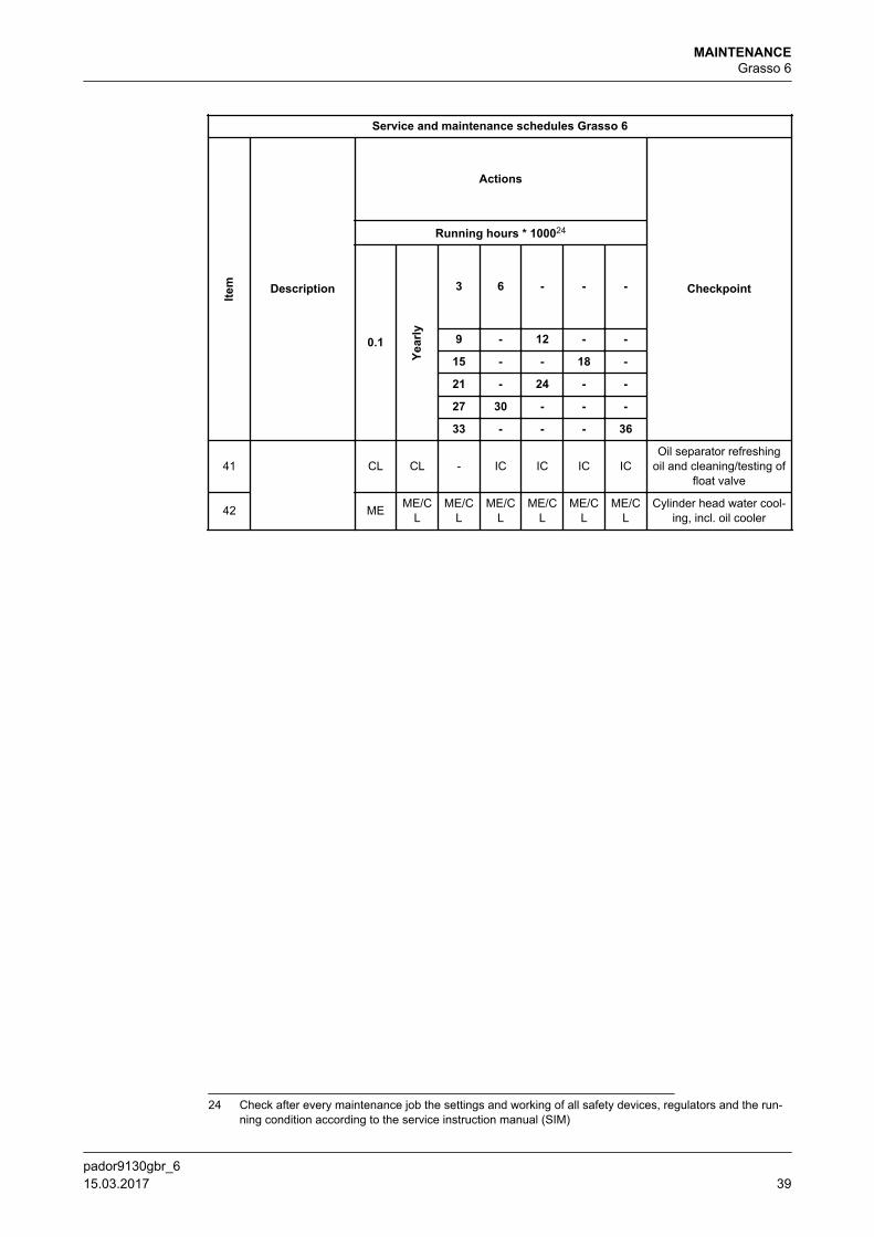
Service and maintenance schedules Grasso 6
Item Description
Actions
Checkpoint
Running hours * 100024
0.1
Year
ly
3 6 - - -
9 - 12 - -
15 - - 18 -
21 - 24 - -
27 30 - - -
33 - - - 36
41 CL CL - IC IC IC ICOil separator refreshing
oil and cleaning/testing offloat valve
42 ME ME/CL
ME/CL
ME/CL
ME/CL
ME/CL
ME/CL
Cylinder head water cool-ing, incl. oil cooler
24 Check after every maintenance job the settings and working of all safety devices, regulators and the run-ning condition according to the service instruction manual (SIM)
MAINTENANCEGrasso 6
pador9130gbr_6 15.03.2017 39
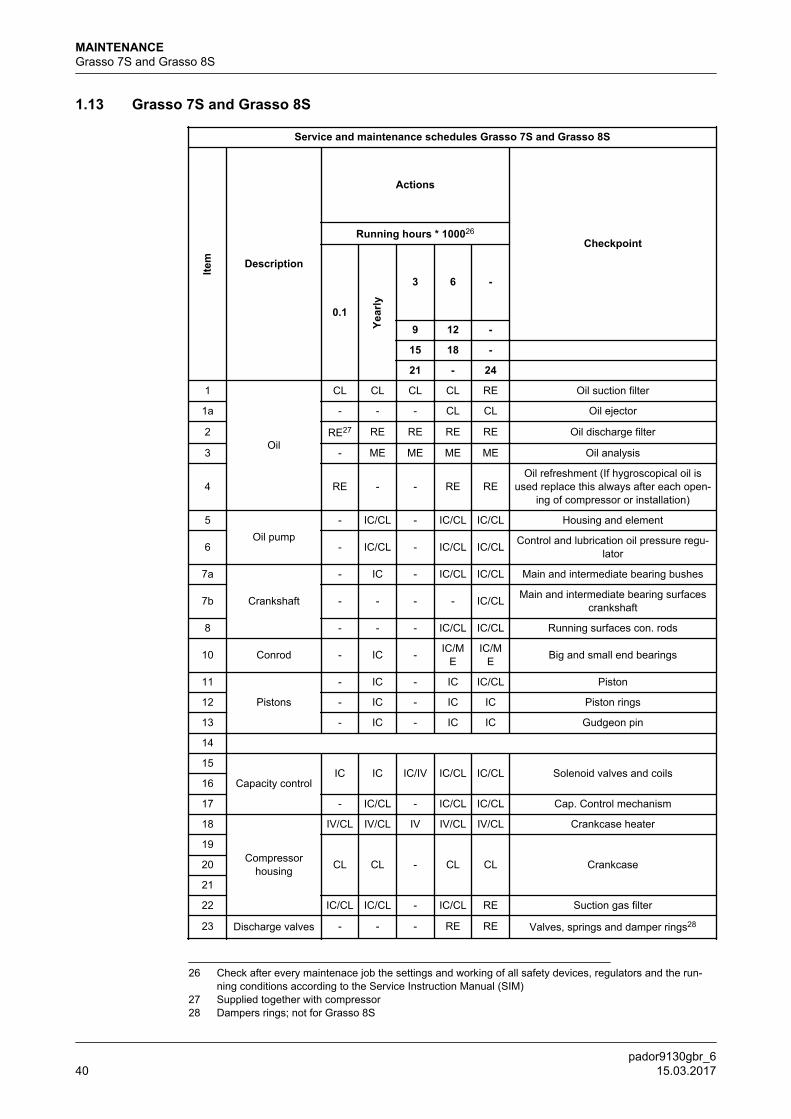
1.13 Grasso 7S and Grasso 8S
Service and maintenance schedules Grasso 7S and Grasso 8S
Item Description
Actions
CheckpointRunning hours * 100026
0.1
Year
ly
3 6 -
9 12 -
15 18 - 21 - 24
1
Oil
CL CL CL CL RE Oil suction filter
1a - - - CL CL Oil ejector
2 RE27 RE RE RE RE Oil discharge filter
3 - ME ME ME ME Oil analysis
4 RE - - RE REOil refreshment (If hygroscopical oil is
used replace this always after each open-ing of compressor or installation)
5Oil pump
- IC/CL - IC/CL IC/CL Housing and element
6 - IC/CL - IC/CL IC/CL Control and lubrication oil pressure regu-lator
7a
Crankshaft
- IC - IC/CL IC/CL Main and intermediate bearing bushes
7b - - - - IC/CL Main and intermediate bearing surfacescrankshaft
8 - - - IC/CL IC/CL Running surfaces con. rods
10 Conrod - IC - IC/ME
IC/ME Big and small end bearings
11
Pistons
- IC - IC IC/CL Piston
12 - IC - IC IC Piston rings
13 - IC - IC IC Gudgeon pin
14 15
Capacity controlIC IC IC/IV IC/CL IC/CL Solenoid valves and coils
16
17 - IC/CL - IC/CL IC/CL Cap. Control mechanism
18
Compressorhousing
IV/CL IV/CL IV IV/CL IV/CL Crankcase heater
19
CL CL - CL CL Crankcase20
21
22 IC/CL IC/CL - IC/CL RE Suction gas filter
23 Discharge valves - - - RE RE Valves, springs and damper rings28
26 Check after every maintenace job the settings and working of all safety devices, regulators and the run-ning conditions according to the Service Instruction Manual (SIM)
27 Supplied together with compressor28 Dampers rings; not for Grasso 8S
MAINTENANCEGrasso 7S and Grasso 8S
pador9130gbr_640 15.03.2017
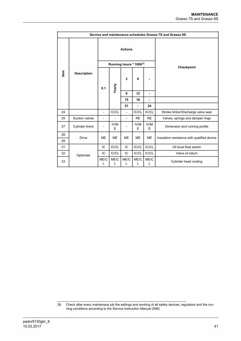
Service and maintenance schedules Grasso 7S and Grasso 8S
Item Description
Actions
CheckpointRunning hours * 100026
0.1
Year
ly
3 6 -
9 12 -
15 18 - 21 - 24
24 - IC/CL - IC/CL IC/CL Stroke limitor/Discharge valve seat
25 Suction valves - - - RE RE Valves, springs and damper rings
27 Cylinder liners - IV/ME - IV/M
EIV/M
E Dimension and running profile
28Drive ME ME ME ME ME Insulation resistance with qualified device
29
31
Optionals
IC IC/CL IC IC/CL IC/CL Oil level float switch
32 IC IC/CL IC IC/CL IC/CL Valve oil return
33 ME/CL
ME/CL
ME/CL
ME/CL
ME/CL Cylinder head cooling
26 Check after every maintenace job the settings and working of all safety devices, regulators and the run-ning conditions according to the Service Instruction Manual (SIM)
MAINTENANCEGrasso 7S and Grasso 8S
pador9130gbr_6 15.03.2017 41
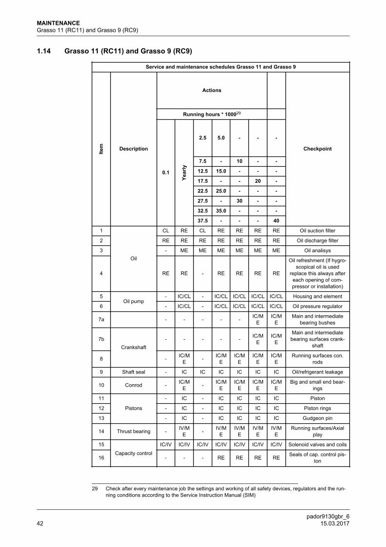
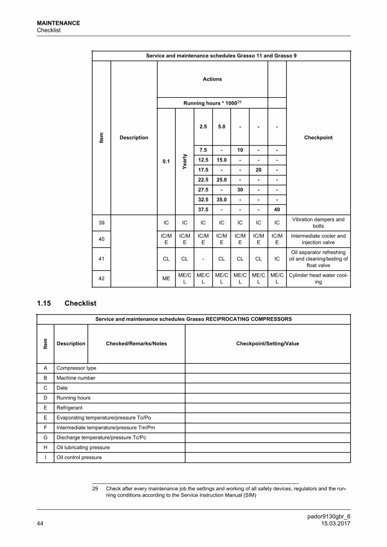
1.14 Grasso 11 (RC11) and Grasso 9 (RC9)
Service and maintenance schedules Grasso 11 and Grasso 9
Item Description
Actions
Checkpoint
Running hours * 100029
0.1
Year
ly
2.5 5.0 - - -
7.5 - 10 - -
12.5 15.0 - - -
17.5 - - 20 -
22.5 25.0 - - -
27.5 - 30 - -
32.5 35.0 - - -
37.5 - - - 40
1
Oil
CL RE CL RE RE RE RE Oil suction filter
2 RE RE RE RE RE RE RE Oil discharge filter
3 - ME ME ME ME ME ME Oil analisys
4 RE RE - RE RE RE RE
Oil refreshment (If hygro-scopical oil is used
replace this always aftereach opening of com-pressor or installation)
5Oil pump
- IC/CL - IC/CL IC/CL IC/CL IC/CL Housing and element
6 - IC/CL - IC/CL IC/CL IC/CL IC/CL Oil pressure regulator
7a - - - - - IC/ME
IC/ME
Main and intermediatebearing bushes
7bCrankshaft
- - - - - IC/ME
IC/ME
Main and intermediatebearing surfaces crank-
shaft
8 - IC/ME - IC/M
EIC/M
EIC/M
EIC/M
ERunning surfaces con.
rods
9 Shaft seal - IC IC IC IC IC IC Oil/refrigerant leakage
10 Conrod - IC/ME - IC/M
EIC/M
EIC/M
EIC/M
EBig and small end bear-
ings
11
Pistons
- IC - IC IC IC IC Piston
12 - IC - IC IC IC IC Piston rings
13 - IC - IC IC IC IC Gudgeon pin
14 Thrust bearing - IV/ME - IV/M
EIV/M
EIV/M
EIV/M
ERunning surfaces/Axial
play
15
Capacity control
IC/IV IC/IV IC/IV IC/IV IC/IV IC/IV IC/IV Solenoid valves and coils
16 - - - RE RE RE RE Seals of cap. control pis-ton
29 Check after every maintenance job the settings and working of all safety devices, regulators and the run-ning conditions according to the Service Instruction Manual (SIM)
MAINTENANCEGrasso 11 (RC11) and Grasso 9 (RC9)
pador9130gbr_642 15.03.2017
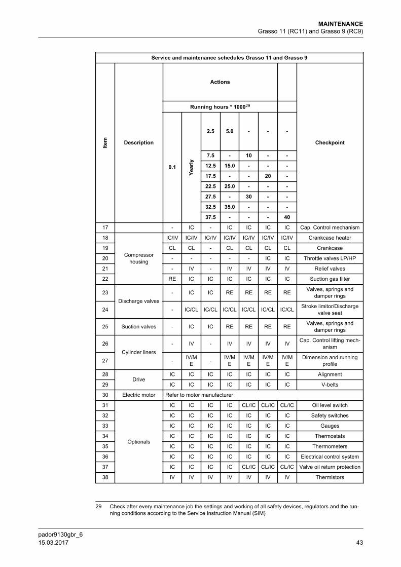
Service and maintenance schedules Grasso 11 and Grasso 9
Item Description
Actions
Checkpoint
Running hours * 100029
0.1
Year
ly
2.5 5.0 - - -
7.5 - 10 - -
12.5 15.0 - - -
17.5 - - 20 -
22.5 25.0 - - -
27.5 - 30 - -
32.5 35.0 - - -
37.5 - - - 40
17 - IC - IC IC IC IC Cap. Control mechanism
18
Compressorhousing
IC/IV IC/IV IC/IV IC/IV IC/IV IC/IV IC/IV Crankcase heater
19 CL CL - CL CL CL CL Crankcase
20 - - - - - IC IC Throttle valves LP/HP
21 - IV - IV IV IV IV Relief valves
22 RE IC IC IC IC IC IC Suction gas filter
23Discharge valves
- IC IC RE RE RE RE Valves, springs anddamper rings
24 - IC/CL IC/CL IC/CL IC/CL IC/CL IC/CL Stroke limitor/Dischargevalve seat
25 Suction valves - IC IC RE RE RE RE Valves, springs anddamper rings
26Cylinder liners
- IV - IV IV IV IV Cap. Control lifting mech-anism
27 - IV/ME - IV/M
EIV/M
EIV/M
EIV/M
EDimension and running
profile
28Drive
IC IC IC IC IC IC IC Alignment
29 IC IC IC IC IC IC IC V-belts
30 Electric motor Refer to motor manufacturer
31
Optionals
IC IC IC IC CL/IC CL/IC CL/IC Oil level switch
32 IC IC IC IC IC IC IC Safety switches
33 IC IC IC IC IC IC IC Gauges
34 IC IC IC IC IC IC IC Thermostats
35 IC IC IC IC IC IC IC Thermometers
36 IC IC IC IC IC IC IC Electrical control system
37 IC IC IC IC CL/IC CL/IC CL/IC Valve oil return protection
38 IV IV IV IV IV IV IV Thermistors
29 Check after every maintenance job the settings and working of all safety devices, regulators and the run-ning conditions according to the Service Instruction Manual (SIM)
MAINTENANCEGrasso 11 (RC11) and Grasso 9 (RC9)
pador9130gbr_6 15.03.2017 43
Service and maintenance schedules Grasso 11 and Grasso 9
Item Description
Actions
Checkpoint
Running hours * 100029
0.1
Year
ly
2.5 5.0 - - -
7.5 - 10 - -
12.5 15.0 - - -
17.5 - - 20 -
22.5 25.0 - - -
27.5 - 30 - -
32.5 35.0 - - -
37.5 - - - 40
39 IC IC IC IC IC IC IC Vibration dampers andbolts
40 IC/ME
IC/ME
IC/ME
IC/ME
IC/ME
IC/ME
IC/ME
Intermediate cooler andinjection valve
41 CL CL - CL CL CL ICOil separator refreshing
oil and cleaning/testing offloat valve
42 ME ME/CL
ME/CL
ME/CL
ME/CL
ME/CL
ME/CL
Cylinder head water cool-ing
1.15 Checklist
Service and maintenance schedules Grasso RECIPROCATING COMPRESSORS
Item Description Checked/Remarks/Notes Checkpoint/Setting/Value
A Compressor type
B Machine number
C Date
D Running hours
E Refrigerant
E Evaporating temperature/pressure To/Po
F Intermediate temperature/pressure Tm/Pm
G Discharge temperature/pressure Tc/Pc
H Oil lubricating pressure
I Oil control pressure
29 Check after every maintenance job the settings and working of all safety devices, regulators and the run-ning conditions according to the Service Instruction Manual (SIM)
MAINTENANCEChecklist
pador9130gbr_644 15.03.2017
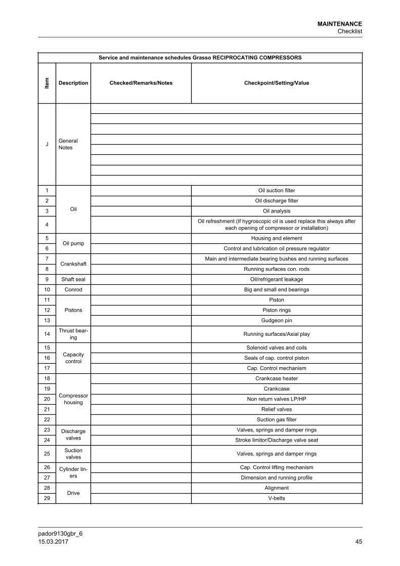
Service and maintenance schedules Grasso RECIPROCATING COMPRESSORS
Item Description Checked/Remarks/Notes Checkpoint/Setting/Value
J GeneralNotes
1
Oil
Oil suction filter
2 Oil discharge filter
3 Oil analysis
4 Oil refreshment (If hygroscopic oil is used replace this always aftereach opening of compressor or installation)
5Oil pump
Housing and element
6 Control and lubrication oil pressure regulator
7Crankshaft
Main and intermediate bearing bushes and running surfaces
8 Running surfaces con. rods
9 Shaft seal Oil/refrigerant leakage
10 Conrod Big and small end bearings
11
Pistons
Piston
12 Piston rings
13 Gudgeon pin
14 Thrust bear-ing Running surfaces/Axial play
15Capacitycontrol
Solenoid valves and coils
16 Seals of cap. control piston
17 Cap. Control mechanism
18
Compressorhousing
Crankcase heater
19 Crankcase
20 Non return valves LP/HP
21 Relief valves
22 Suction gas filter
23 Dischargevalves
Valves, springs and damper rings
24 Stroke limitor/Discharge valve seat
25 Suctionvalves Valves, springs and damper rings
26 Cylinder lin-ers
Cap. Control lifting mechanism
27 Dimension and running profile
28Drive
Alignment
29 V-belts
MAINTENANCEChecklist
pador9130gbr_6 15.03.2017 45
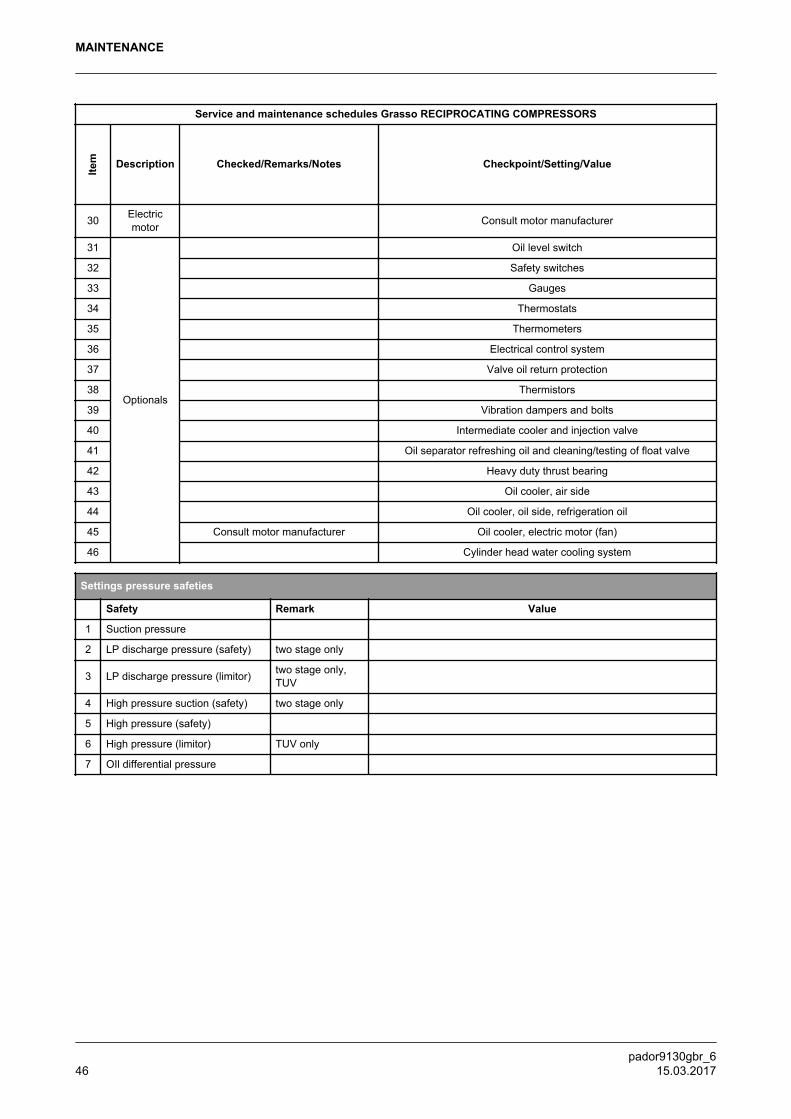
Service and maintenance schedules Grasso RECIPROCATING COMPRESSORS
Item Description Checked/Remarks/Notes Checkpoint/Setting/Value
30 Electricmotor Consult motor manufacturer
31
Optionals
Oil level switch
32 Safety switches
33 Gauges
34 Thermostats
35 Thermometers
36 Electrical control system
37 Valve oil return protection
38 Thermistors
39 Vibration dampers and bolts
40 Intermediate cooler and injection valve
41 Oil separator refreshing oil and cleaning/testing of float valve
42 Heavy duty thrust bearing
43 Oil cooler, air side
44 Oil cooler, oil side, refrigeration oil
45 Consult motor manufacturer Oil cooler, electric motor (fan)
46 Cylinder head water cooling system
Settings pressure safeties
Safety Remark Value
1 Suction pressure
2 LP discharge pressure (safety) two stage only
3 LP discharge pressure (limitor) two stage only,TUV
4 High pressure suction (safety) two stage only
5 High pressure (safety)
6 High pressure (limitor) TUV only
7 OIl differential pressure
MAINTENANCE
pador9130gbr_646 15.03.2017
MAINTENANCE
pador9130gbr_6 15.03.2017 47
GEA Group is a global engineering company with multi-billion euro sales and operations in more than 50 countries. Founded in 1881, the company is one of the largest providers of innovative equipment and process technology. GEA Group is listed in the STOXX® Europe 600 Index.
We live our values.Excellence • Passion • Integrity • Responsibility • GEA-versity
GEA RefrigerationGEA Refrigeration Netherlands N.V.Parallelweg 255223 AL ‘s-Hertogenbosch,Netherlands
Phone +31 (0)73 6203 911
[email protected] gea.com