Embed Size (px)
Citation preview
EUROPEAN SOUTHERN OBSERVATORY
Organisation Europeene pour des Recherches Astronomiques dans l’Hemisphere AustralEuropaische Organisation fur astronomische Forschung in der sudlichen Hemisphare
ESO - European Southern ObservatoryKarl-Schwarzschild Str. 2, D-85748 Garching bei Munchen
Very Large Telescope
Paranal Science Operations
GRAVITY Template Manual
Doc. No. VLT-MAN-ESO-15830-3523
Issue 99, Date 01/12/2016
Gravity consortium & IOT 01/12/2016Prepared . . . . . . . . . . . . . . . . . . . . . . . . . . . . . . . . . . . . . . . . . .
Date Signature
S. MieskeApproved . . . . . . . . . . . . . . . . . . . . . . . . . . . . . . . . . . . . . . . . . .
Date Signature
A. KauferReleased . . . . . . . . . . . . . . . . . . . . . . . . . . . . . . . . . . . . . . . . . .
Date Signature

GRAVITY Template Manual VLT-MAN-ESO-15830-3523 ii
This page was intentionally left blank

GRAVITY Template Manual VLT-MAN-ESO-15830-3523 iii
Change Record
Issue/Rev. Date Section/Parag. affected Remarks
98 30/04/16 Document created99 01/12/16 Acquisition template split for SF and DF
99.1 31/01/17 Tables 1 and 2

GRAVITY Template Manual VLT-MAN-ESO-15830-3523 iv
This page was intentionally left blank

GRAVITY Template Manual VLT-MAN-ESO-15830-3523 v
Contents
1 INTRODUCTION 1
1.1 Scope . . . . . . . . . . . . . . . . . . . . . . . . . . . . . . . . . . . . . . . . 1
1.2 Contact information . . . . . . . . . . . . . . . . . . . . . . . . . . . . . . . . 1
1.3 Period of validity of this manual . . . . . . . . . . . . . . . . . . . . . . . . . . 1
1.4 Glossary . . . . . . . . . . . . . . . . . . . . . . . . . . . . . . . . . . . . . . . 1
1.5 Modifications for P99 . . . . . . . . . . . . . . . . . . . . . . . . . . . . . . . . 2
1.5.1 Instrument . . . . . . . . . . . . . . . . . . . . . . . . . . . . . . . . . 2
1.5.2 Templates . . . . . . . . . . . . . . . . . . . . . . . . . . . . . . . . . . 2
2 GRAVITY TEMPLATES 3
2.1 Observing modes . . . . . . . . . . . . . . . . . . . . . . . . . . . . . . . . . . 3
2.2 The acquisition template . . . . . . . . . . . . . . . . . . . . . . . . . . . . . . 4
2.2.1 Which star is which in single-field mode? . . . . . . . . . . . . . . . . . 4
2.2.2 Which star is which in dual-field mode? . . . . . . . . . . . . . . . . . . 5
2.2.3 Proper motion and parallax . . . . . . . . . . . . . . . . . . . . . . . . 5
2.2.4 STRAP guiding with the ATs . . . . . . . . . . . . . . . . . . . . . . . 5
2.2.5 Science and fringe-tracking target K magnitudes . . . . . . . . . . . . . 5
2.2.6 Field guiding H magnitude . . . . . . . . . . . . . . . . . . . . . . . . . 6
2.2.7 Selecting the polarisation mode . . . . . . . . . . . . . . . . . . . . . . 6
2.2.8 Selecting the resolution mode . . . . . . . . . . . . . . . . . . . . . . . 6
2.2.9 Fringe-tracker . . . . . . . . . . . . . . . . . . . . . . . . . . . . . . . . 6
2.2.10 Dual-field mode . . . . . . . . . . . . . . . . . . . . . . . . . . . . . . . 7
2.3 The observation template . . . . . . . . . . . . . . . . . . . . . . . . . . . . . 7
2.3.1 Integration time . . . . . . . . . . . . . . . . . . . . . . . . . . . . . . . 8
2.3.2 Execution time . . . . . . . . . . . . . . . . . . . . . . . . . . . . . . . 8
2.3.3 Acquisition camera frames . . . . . . . . . . . . . . . . . . . . . . . . . 10
2.4 User keywords . . . . . . . . . . . . . . . . . . . . . . . . . . . . . . . . . . . . 10
2.4.1 GRAVITY dual acq.tsf . . . . . . . . . . . . . . . . . . . . . . . . . . . 11
2.4.2 GRAVITY single acq.tsf . . . . . . . . . . . . . . . . . . . . . . . . . . 12
2.4.3 Acquisition keywords . . . . . . . . . . . . . . . . . . . . . . . . . . . . 12
2.4.4 GRAVITY single obs exp.tsf, GRAVITY single obs calibrator.tsf, GRAV-ITY dual obs exp.tsf and GRAVITY dual obs calibrator.tsf . . . . . . 14
GRAVITY Template Manual VLT-MAN-ESO-15830-3523 1
1 INTRODUCTION
1.1 Scope
This document describes the observing templates for the 2nd generation VLTI instrumentGRAVITY. This document will need to be used for preparing GRAVITY observations forobservations in P99. Like with other VLT instruments, observations with GRAVITY arecarried out making use of observation blocks (OBs). The OBs must be created by the userduring Phase-2 preparation with the P2PP tool. An OB is a set of observing templates thatdescribe and detail the target acquisition and the data recording. The user has to define thevalues of the template keywords (parameters).
The Template Manual requires the user to have some basic understanding of the GRAVITYinstrument. If you are a first time user, we recommend to read the GRAVITY User Manualfor P99:
http://www.eso.org/sci/facilities/paranal/instruments/gravity/doc
The OBs are prepared with the P2PP tool. For its installation and documentation of its us-age see: http://www.eso.org/observing/p2pp. GRAVITY specific templates will be down-loaded by the P2PP tool itself. If help is needed, we kindly point the reader towards the stepby step tutorial for using P2PP with the GRAVITY templates.
Finally, the VLTI manual needs to be consulted for description of the system which are notinstrument specific (e.g. AT configurations, limited magnitudes for field guiding, etc.) thatone needs for preparing VLTI observations: link to VLTI User Manual
1.2 Contact information
In case of questions or suggestions related to Phase-2 preparation, please contact the ESOUser Support Department ([email protected]).
1.3 Period of validity of this manual
This manual is valid for observations with GRAVITY during ESO Period 99, starting April1st, 2017 and ending October 31st, 2017.
1.4 Glossary
• Constrain Set (CS)List of requirements for the conditions of the observation that is given inside an OB.OBs are only executed under this set of minimum conditions.
• Observation Block (OB)An Observation Block is the smallest schedulable entity for the VLT. It consists of asequence of Templates. Usually, one Observation Block include one target acquisitionand up to three exposure templates.
• Observation Description (OD)A sequence of templates used to specify the observing sequences within one or moreOBs.
GRAVITY Template Manual VLT-MAN-ESO-15830-3523 2
• Observation Toolkit (OT)Tool used to create queues of OBs for later scheduling and possible execution (servicemode).
• Proposal Preparation and Submission (Phase-I)The Phase-I begins right after the CfP (Call-for-Proposals) and ends at the deadline forCfP. During this period the potential users are invited to prepare and submit scientificproposals. For more information, see:
http://www.eso.org/observing/proposals.index.html
• Phase-2 Proposal Preparation (P2PP)Once proposals have been approved by the ESO Observation Program Committee (OPC),users are notified and the Phase-2 begins. In this phase, users are requested to preparetheir accepted proposals in the form of OBs, and to submit them by Internet (in caseof service mode). The software tool used to build OBs is called the P2PP tool. It isdistributed by ESO and can be installed on the personal computer of the user. See:
http://www.eso.org/observing/p2pp.
• Service Mode (SM)In service mode (opposite of the “Visitor-Mode”), the observations are carried out bythe ESO Paranal Science-Operation staff (PSO) alone. Observations can be done at anytime during the period, depending on the CS given by the user. OBs are put into aqueue schedule in OT which later sends OBs to the instrument.
• TemplateA template is a sequence of operations to be executed by the instrument. The observa-tion software of an instrument dispatches commands written in templates not only toinstrument modules that control its motors and the detector, but also to the telescopesand VLTI sub-systems.
• Template signature file (TSF)File which contains template input parameters.
• Visitor Mode (VM)The classic observation mode. The user is on-site to supervise his/her program execution.
1.5 Modifications for P99
1.5.1 Instrument
P99 sees an expansion in the possible uses of GRAVITY by the community. First, GRAVITY isoffered with the UTs and their MACAO systems. This increases the offered limiting magnitudeby three. Secondly, the instrument’s low spectral resolution setting can be used (only) in dual-field mode.
1.5.2 Templates
For P99, two template changes are implemented with respect to the templates from the pastperiod and science verification.
GRAVITY Template Manual VLT-MAN-ESO-15830-3523 3
• The biggest change is the split of the acquisition template according to single or dualfield set-up. The split results in the absence of DF keywords in a SF observation, whichshould increase the transparency and ease of use. For DF observations there are nodifferences to the acquistion template apart from the name (see Sect. 2.2.2).
• The second change is the addition of a keyword that describes the expected visibilitywhich is introduced for operational reasons.
• We would also like to make the reader aware of an improvement in the table of recom-mended exposure times
2 GRAVITY TEMPLATES
The number of GRAVITY OB templates for P99 is minimal and grouped according to themode, i.e. either single-field (SF, on-axis fringe-tracking using the science star) or dual field(DF, off-axis fringe tracking using a reference star). Thus a SF and DF template for (1) preset,acquisition and fringe search and (2) fringe observation (for either science or calibrator). Thetemplates need user-provided input for a limited number of keywords.
2.1 Observing modes
A description of the GRAVITY observing modes can be found on the public GRAVITYweb pages for the science users. In summary, the instrument consists of two independentinterferometers, the so-called fringe-tracker (FT) and the science spectrometer (SC). Thefringe-tracker stabilizes the fringes on the science target (in single-field mode) or a nearbyfringe-tracking reference star (in dual-field mode). This observing strategy allows exposuresof up to 30 s on the science spectrometer without losing significant fringe contrast. Theobserving wavelength is for both channels the K-band (2.0 − 2.45µm). In P99 (as in the pastperiod) only the imaging mode is offered. The astrometric mode will be offered at a laterstage. The following setups of GRAVITY can be used for P99:
• Two distinct field modes: the dual-field and the single-field. In single-field mode thelight of the science target is split 50/50 between fringe-tracker and science channel. Indual-field mode a nearby object (separation with the science target 1.5′′ ≤ d ≤ 4′′ forATs and 0.4” ≤ d ≤ 2” for UTs) is used for fringe-tracking. All the light of the sciencetarget is injected into the science channel.
• Three spectral setups for the science spectrometer :
1. Low Resolution R ∼ 20 (DF only)
2. Medium Resolution R ∼ 500 (SF and DF)
3. High Resolution R ∼ 4000 (SF and DF)
Note, the resolution of the fringe-tracker is fixed at R ∼ 20 and its data is alwaysdelivered in the fits files. Hence the reason for low resolution for the SC spectrometer indual field only.
• Two polarisation modes for the fringe-tracker & science spectrometer:
GRAVITY Template Manual VLT-MAN-ESO-15830-3523 4
1. Split polarisation (only linear polarisation).
2. Combined polarisation.
For the best visibility accuracy ”split polarisation” is recommended. In case of faintobjects and SNR limitations ”combined polarisation” is recommended. The polarisationmode has to be the same for fringe-tracker and science spectrometer.
• Telescope configurations of four ATs or four UTs.
Table 1 in Sect. 2.3.2 gives some preliminary guidelines for DIT values for the science spec-trometer (the table has been updated with respect to the past period). The fringe-tracker DITis set automatically based on the object’s correlated K-band magnitude. It should be notedthat the STRAP tip-tilt unit on the ATs or the AO unit MACAO on the UTs is a prerequisitefor observations with GRAVITY. For proper MACAO/STRAP operations the Coude guidestar must be suitably bright for guiding. See VLTI user manual for the limiting brightness.
2.2 The acquisition template
According to P2PP rules, the first template in an OB must be an acquisition template. ForGRAVITY, the name of this template is either GRAVITY single acq or GRAVITY dual acq.The sequence of these templates are very similar. They start by a “preset”: the targetcoordinates (α, δ) are sent to the telescopes and the delay lines, so they can slew to theposition corresponding to the target coordinates at preset time. Once the VLTI is trackingand Coude-guiding, the target(s) should be seen on the Acquisition Camera of GRAVITY.Internal actuators take care of the field rotation and ensure that the target(s) is/are injectedinto the fringe-tracker and science channel fibers. In dual-field mode the internal differentialdelay lines are preset such that they compensate the differential optical path between the twoobjects. The final step in the acquisition template is to search and track fringes. The searchuses a saw tooth pattern around the nominal fringe position (i.e. zero OPD). As soon as thefringes are found and the control loop is locked the acquisition template is finished and thescience exposures defined in the observation template can commence.
What follows is a detailed description of some important definitions and parameters of theacquisition templates. The user is advised to read through these subsections in order to createthe acquisition template correctly.
2.2.1 Which star is which in single-field mode?
As GRAVITY observations may need up to three different objects (telescope Coude guidestar, instrument fringe-track object and instrument science object), the user can find in thesetwo subsections details on how the different objects are defined in the acquisition template.
In GRAVITY SF mode, the science star and the FT star are the same object. The SFacquisition template only lists the keyword related to the science object. In standard observing,one can either chose telescope on-axis or off-axis Coude guiding. In telescope on-axis guiding,the observation uses only one star to guide the telescope, to track the fringes and to record thescience data. If the science star is not bright enough for the optical telescope guiding system,another, off-axis star can be chosen to guide the telescope. This is explained in detail in theVLTI user manual.

GRAVITY Template Manual VLT-MAN-ESO-15830-3523 5
2.2.2 Which star is which in dual-field mode?
In order to make efficient use of the VLTI field of view of 4” (ATs) and 2” (UTs), GRAVITYDF observations are preset at the telescope to coordinates that correspond to a position inbetween the FT and SC source. The system does this automatically based on the coordinatesand the separation provided in the acquisition template. (The coordinates in the target fieldare those of the FT star.) This implementation means that coude guiding in dual-field isalways off-axis. Therefore, the user has to chose “setuptfile” in dual-field model and providethe properties of the coude guide star. In most cases, the latter is the FT star as it is usuallythe brightest both in the optical (for STRAP) and in the near-IR (for fringe tracking). Howeverthe guide star can also be a third object (distance restrictions apply, see VLTI user manual)when both the FT and SC objects are too faint for STRAP. It is also possible that the targetof scientific interest is the Coude guide star, e.g. when it is much bluer than the FT objectand therefore the brighter object in V for STRAP guiding.
2.2.3 Proper motion and parallax
The knowledge of the current object coordinates (RA,DEC) determines the ability to predictthe fringe position. For targets with a proper motion larger than 50 mas/year or a parallaxgreater than 100 mas it is important to provide both values in the acquisition template. If notprovided, the fringe search can take significantly longer than normal. For an effective use ofthe allocated time we request that the known proper motions are incorporated into the OBs.
2.2.4 STRAP guiding with the ATs
The Auxiliary Telescopes guide by means of the STRAP tip-tilt sensor. The VLTI user manualgives details on STRAP which we summarize here. It is not possible under any weatherconditions to perform GRAVITY observations without the telescopes properly guiding. Therequirements for successful STRAP guiding are:
• The guide star must be brighter than V = 13m. Note however that the tip-tilt correctiondrops significantly in K with a STRAP guide star fainter than 11th magnitude and thatby Coude guiding on a star of V = 13m, the K-band limit for the SC object drops by 1magnitude.
• The guide star must be within a radius of <15” from the science target, implementingthe limits for fringe-tracking at the VLTI. The effective tip-tilt correction drops withdistance from the science target, so it is recommended that the user chooses a guidestar as close as possible. A rule of thumb is that the magnitude limit is brighter by 1magnitude for every 15” from the science object.
• It is requested that the faintest (if variable) V magnitude of the guide star is given inthe keyword COU.GS.MAG.
2.2.5 Science and fringe-tracking target K magnitudes
The SEQ.FT.ROBJ.MAG keyword should be used to specify the correlated K magnitude of thefringe-tracking object. This value is the −2.5 ×10 log(Visibility) + K for a visibility expected

GRAVITY Template Manual VLT-MAN-ESO-15830-3523 6
on the longest baseline of an ”open telescope triplet” (or non-closed triangle for example AT1-AT2, AT2-AT3 and AT3-AT4). This baseline does not correspond to the longest baseline ofthe quadruplet as fringe tracking will make use of so-called bootstrapping (i.e. if one knows thezero-OPD on two of the baselines of a closed triangle then the remaining one can be deduced,e.g. if ZOPD on baseline 12 and 23 are known then the ZOPD on 13 can be deduced).
In single-field mode the correlated K magnitude is equivalent to the science target correlatedK magnitude. In dual-field mode this corresponds to the correlated K magnitude of thereference object used for fringe-tracking. In dual-field mode the correlated K magnitude ofthe science target should be independently provided using the keyword SEQ.INS.SOBJ.MAG.
2.2.6 Field guiding H magnitude
The SEQ.FI.HMAG keyword should be used to specify the uncorrelated H magnitude of thescience source (in single field) or the H-band brightest of the two objects (SC or FT) in dualfield. The Acquisition Camera uses the H band light for the object acquisition and slow fieldguiding.
2.2.7 Selecting the polarisation mode
Observations can be done in polarisation split or combined mode. In split mode a Wollastonprism is introduced in the beam. It splits the two linear polarisations on the detector. Thisincreases the visibility accuracy as polarisation phase shifts originating from the optical trainare separated. The disadvantage however is that the light is spread over twice as manypixels, i.e. the read noise is increased. In case of bright targets (where read noise can beneglected) the split mode is to be preferred. The combined mode should be used in caseof faint objects, where read noise dominates the SNR. Currently FT and SC have to be inthe same polarisation mode. Polarisation split mode can be chosen by setting the keywordsINS.FT.POL and INS.SPEC.POL to IN. The combined mode is chosen with OUT.
2.2.8 Selecting the resolution mode
In P99 in SF two spectral resolutions are offered (medium and high), whereas in DF all threecan be chosen. The spectral mode can be selected by setting the keyword INS.SPEC.RES toLOW, MED or HIGH. The choice of resolution mode depends on whether it is SF or DF, thetarget brightness, science goals, desired visibility accuracy (SNR) and available observing time.As a ”rule-of-thumb” the user should consider high resolution (and combined polarisation) onlyfor targets brighter than K<5.5. Otherwise the necessary on-source integration time exceeds1 h for any reasonable SNR. Fainter targets should be observed in medium resolution (DFand SF) or low resolution (DF only). The reason why low resolution is offered in DF onlyis that the FT resolution is the same as SC and those SC low resolution in SF would implyduplication of data (as the same polarization is imposed).
2.2.9 Fringe-tracker
GRAVITY by default operates always with the internal fringe-tracker. It is not possible touse GRAVITY without this system. The DIT of the fringe-tracker is automatically selectedbased on the correlated K magnitude of the FT object provided by the user.
Currently, fringe-tracking is feasible under the following conditions:
GRAVITY Template Manual VLT-MAN-ESO-15830-3523 7
• Seeing below 1.5 arcseconds
• The transparency should be CLR or better.
• τ0 above 1.5 ms
• Altitude above 40 degrees
• The target must not be brighter than K=−2m because the fringe-tracker saturates oth-erwise.
• Under good seeing (better than 1”) the limiting correlated magnitude is K=6m in single-field mode and K=6.5m in dual-field mode on the ATs. For seeing between 1-1.5” thelimiting magnitude is K=5m in single-field mode and K=5.5m in dual-field. The limitingmagnitudes with the UTs are 3 magnitudes fainter for each of the two meteorologicalboundary condition.
• The correlated magnitude has to fulfill the above criteria on at least three baselinesthat do not form a triangle (e.g. 13/23/24, or 12/13/14). In this case it is possible toboot-strap other baselines with lower visibilities.
These numbers should be regarded as preliminary given that knowledge of the performancesof a new instrument under certain weather conditions is limited.
2.2.10 Dual-field mode
In dual-field mode the R.A. and Dec. offset in [mas] of the science target relative to the fringe-tracking object has to be provided with the keywords SEQ.INS.SOBJ.X and SEQ.INS.SOBJ.Y,i.e. the coordinates of the FT source are the reference. As a result, these coordinates alsoneed to be filled out in the ”target” tab in P2PP (i.e. the TEL.TARG keywords in Sect. 2.4).The binary separation should be accurate to better than 100 mas. If the separation is poorlyknown the time to fringe search might increase significantly, i.e. the observing efficiency couldbe reduced. See also Sect. 2.2.2 for the definition of the FT, SC and Coude guide objects.The requirements for the dual-field mode are:
• Science target correlated K magnitude must not differ more than 3 mag from fringe-tracker source.
• The separation between fringe-tracker source and science target must be within the range[0.4 ′′, 2 ′′] for UTs and [1.5 ′′, 4 ′′] for ATs.
2.3 The observation template
Following the acquistion template, the user has to chose a science observation template. Thistemplate is the second and the last one in any GRAVITY OB. It is used to record the fringeand sky data. There are currently only four templates:
1. single-field science target, GRAVITY single obs exp
2. single-field calibrator, GRAVITY single obs calibrator
3. dual-field science target, GRAVITY dual obs exp

GRAVITY Template Manual VLT-MAN-ESO-15830-3523 8
4. dual-field calibrator, GRAVITY dual obs calibrator
The templates use identical keywords. The appropriate template should be chosen accord-ing to the mode (single/dual) and the target (science/calibrator). Each template allows asequence of exposures. The sequence consists of science target exposures (OBJECT) and off-source exposures (SKY). The observing sequence can be defined by the user with the keywordSEQ.OBSSEQ. The sequence can contain any combination of object (O) and sky (S) exposures.The SEQ.SKY.X and SEQ.SKY.Y are used to select the offset of the sky exposure. These off-sets will move the GRAVITY internal actuators in the directions given. Make sure that indual-field the sky offset will not position the SC star on the FT fibre or vice versa. Safest isto offset perpendicular to the binary separation vector.
2.3.1 Integration time
The DIT of the fringe-tracker is automatically set based on the provided correlated K-bandmagnitude. The DIT DET2.DIT for the science spectrometer should be chosen according tothe mode and science target uncorrelated K-band magnitude. Table 1 lists the suggestedDITs for the various modes and magnitudes. The number of frames (NDIT) per exposure canbe specified with DET2.NDIT.OBJECT for the science exposure and DET2.NDIT.SKY for the skyexposure.The following requirements apply:
1. The total exposure time (DIT x NDIT) must not exceed 300 s.
2. The number of science frames (NDIT) must not exceed 300 and be more than 10.
Note: Stability of the instrument asssessed during the commissioning shows that the DITof the Science and Calibrator targets need not be the same, contrary to VLTI practice andexperience with the other instruments.
2.3.2 Execution time
A conservative estimate of a CAL/SCI sequence is one hour. Each acquisition takes roughly10 min (it can take longer on faint targets). About 20 min have to be spent for object and skyexposures. Note: The calibrator has to be observed with the same configuration and thusthe total execution time for one calibrated visibility spectrum is 60 minutes (SCI-CAL).
For this period, we apply the following model for the calculation of the execution time for SF:
exectime = 600 sec + DIT × NDIT × NEXP + 40 sec × NEXP (1)
and for DF:
exectime = 900 sec + DIT × NDIT × NEXP + 40 sec × NEXP, (2)
where NEXP is the number of exposure entered in the observing template keyword OBSSEQ(see following section). For background limited data, the default is to use the same numberof NDIT for S(ky) and O(bject).
A typical example on how to fill the 30 minutes would be the following:
In single-field: If we have a OSO sequence, we have to subtract 600 min offset and 3*40 secoffset, leaving 1080 sec, or 360 seconds for each exposure, which is too much.

GRAVITY Template Manual VLT-MAN-ESO-15830-3523 9
Table 1: Summary of available modes, spectral and polarisation configurations, telescopes(Tel), uncorrelated K magnitudes (K) and suggested DITs for the science spectrometer. In DFthe same DITs are adopted as in single-field except that the appropriate DF DIT correspondsto that of a star 0.7 mag brighter (Kdf=K - 0.7). This reflects that in dual-field the light is notsplit 50/50 between FT and SC. Likewise for UT observations, one choses a AT SF DIT thatcorresponds to a star 3 (or 3.7) magnitudes brighter than the UT science target. Note thatthe DIT for the calibrator can be different from the one used for the science object. P99 isthe first period with UT observations and the recommended DITs in this table are highlypreliminary. Performances are strongly seeing dependent.
Mode Spec Pol Tel K DIT [s]Single-field MR Comb AT -1.0<K≤1.0 0.3Single-field MR Comb AT 1.0<K≤2.5 1.0Single-field MR Comb AT 2.5<K≤3.0 3.0Single-field MR Comb AT 3.0<K≤3.5 5.0Single-field MR Comb AT 3.5<K≤4.5 10.0Single-field MR Comb AT 5.0<K≤9.0 30.0Single-field MR Split AT -2.0<K≤0.0 0.3Single-field MR Split AT 0.0<K≤1.5 1.0Single-field MR Split AT 1.5<K≤2.5 3.0Single-field MR Split AT 2.5<K≤3.0 5.0Single-field MR Split AT 3.0<K≤4.0 10.0Single-field MR Split AT 4.0<K≤9.0 30.0Single-field HR Comb AT -2.0<K≤-0.5 1.0Single-field HR Comb AT -0.5<K≤0.5 5.0Single-field HR Comb AT 0.5<K≤2.0 10.0Single-field HR Comb AT 2.0<K≤9.0 30.0Single-field HR Split AT -2.0<K≤-0.5 3.0Single-field HR Split AT -0.5<K≤0.0 5.0Single-field HR Split AT 0.0<K≤ 1.0 10.0Single-field HR Split AT 1.0<K≤ 4.5 30.0Dual-field all all AT K − 0.7 -Single-field all all UT K − 3.0 -Dual-field all all UT K − 3.7 -

GRAVITY Template Manual VLT-MAN-ESO-15830-3523 10
Table 2: Overview of DIT and recommended NDIT values for different number of exposuresfor SF and DF mode. The value DIT* NDIT should be less than 300 seconds, while the totalexecution time of the OB is <=1800 seconds. The number of science frames (NDIT) must notexceed 300.
DIT Nexp NDIT Execution time NDIT Execution time(s) (O S ..) SF SF DF DF1.0 2 300 1280 300 1580
3 300 1620 260 18004 260 1800 185 18005 200 1800 140 1800
3.0 2 100 1280 100 15803 100 1620 85 17854 85 1780 60 17805 65 1775 45 1775
5.0 2 60 1280 60 15803 60 1620 50 17704 50 1760 35 17605 40 1800 25 1725
10.0 2 30 1280 30 15803 30 1620 25 17704 25 1760 18 17805 20 1800 14 1800
30.0 2 10 1280 10 15803 10 1620 - -
So, we typically need to use OSOS, leaving 1040 sec, or 260 sec per exposure. So, for magnitude1 in MR, this would typically be DIT=1s and NDIT=260. Or, for magnitude 1 in HR, thiswould typically be DIT=30s and NDIT=8.
2.3.3 Acquisition camera frames
The internal Acquisition Camera is used for the object acquisition as well as slow pupil andtilt guiding. By default each science exposure contains one acquisition frame (NDIT=1) withan integration time DIT=0.7 s. This means the user obtains an H-band image of the sciencetarget with roughly 4” field-of-view.
2.4 User keywords
In the following tables, we give for each template the keywords that have to be set by the userwith the P2PP tool.
GRAVITY Template Manual VLT-MAN-ESO-15830-3523 11
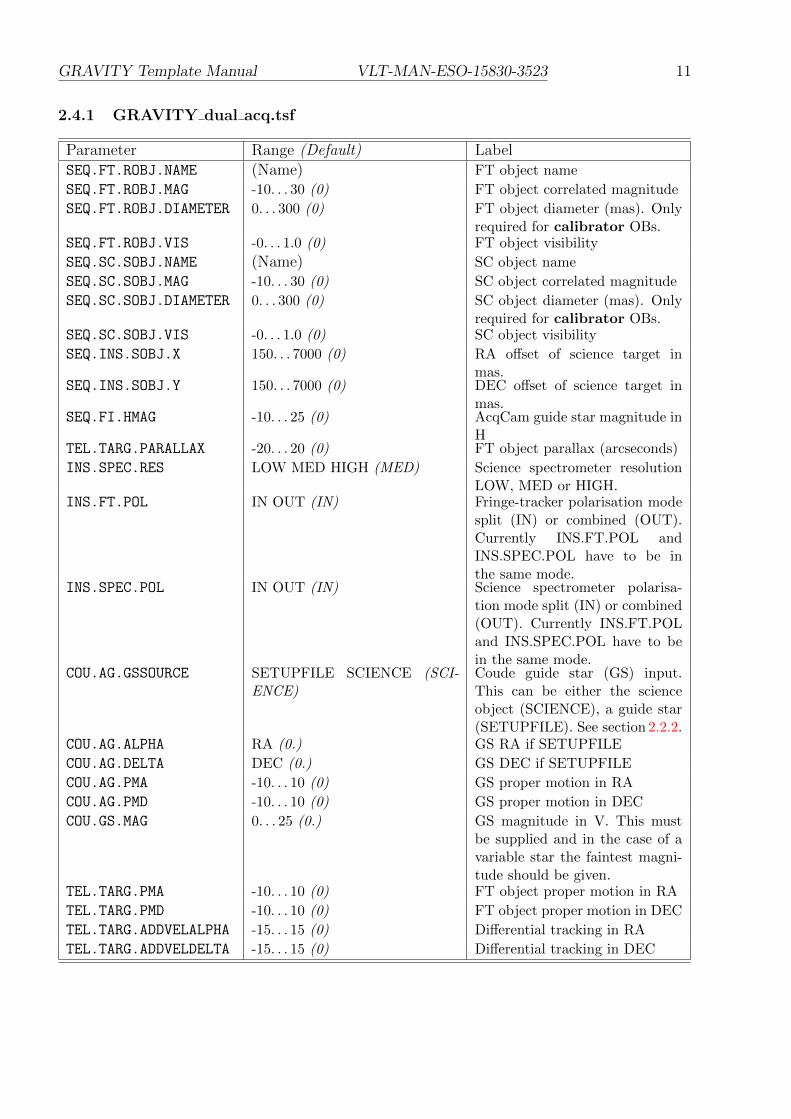
2.4.1 GRAVITY dual acq.tsf
Parameter Range (Default) LabelSEQ.FT.ROBJ.NAME (Name) FT object name
SEQ.FT.ROBJ.MAG -10. . . 30 (0) FT object correlated magnitude
SEQ.FT.ROBJ.DIAMETER 0. . . 300 (0) FT object diameter (mas). Onlyrequired for calibrator OBs.
SEQ.FT.ROBJ.VIS -0. . . 1.0 (0) FT object visibility
SEQ.SC.SOBJ.NAME (Name) SC object name
SEQ.SC.SOBJ.MAG -10. . . 30 (0) SC object correlated magnitude
SEQ.SC.SOBJ.DIAMETER 0. . . 300 (0) SC object diameter (mas). Onlyrequired for calibrator OBs.
SEQ.SC.SOBJ.VIS -0. . . 1.0 (0) SC object visibility
SEQ.INS.SOBJ.X 150. . . 7000 (0) RA offset of science target inmas.
SEQ.INS.SOBJ.Y 150. . . 7000 (0) DEC offset of science target inmas.
SEQ.FI.HMAG -10. . . 25 (0) AcqCam guide star magnitude inH
TEL.TARG.PARALLAX -20. . . 20 (0) FT object parallax (arcseconds)
INS.SPEC.RES LOW MED HIGH (MED) Science spectrometer resolutionLOW, MED or HIGH.
INS.FT.POL IN OUT (IN) Fringe-tracker polarisation modesplit (IN) or combined (OUT).Currently INS.FT.POL andINS.SPEC.POL have to be inthe same mode.
INS.SPEC.POL IN OUT (IN) Science spectrometer polarisa-tion mode split (IN) or combined(OUT). Currently INS.FT.POLand INS.SPEC.POL have to bein the same mode.
COU.AG.GSSOURCE SETUPFILE SCIENCE (SCI-ENCE)
Coude guide star (GS) input.This can be either the scienceobject (SCIENCE), a guide star(SETUPFILE). See section 2.2.2.
COU.AG.ALPHA RA (0.) GS RA if SETUPFILE
COU.AG.DELTA DEC (0.) GS DEC if SETUPFILE
COU.AG.PMA -10. . . 10 (0) GS proper motion in RA
COU.AG.PMD -10. . . 10 (0) GS proper motion in DEC
COU.GS.MAG 0. . . 25 (0.) GS magnitude in V. This mustbe supplied and in the case of avariable star the faintest magni-tude should be given.
TEL.TARG.PMA -10. . . 10 (0) FT object proper motion in RA
TEL.TARG.PMD -10. . . 10 (0) FT object proper motion in DEC
TEL.TARG.ADDVELALPHA -15. . . 15 (0) Differential tracking in RA
TEL.TARG.ADDVELDELTA -15. . . 15 (0) Differential tracking in DEC

GRAVITY Template Manual VLT-MAN-ESO-15830-3523 12
2.4.2 GRAVITY single acq.tsf
Parameter Range (Default) LabelSEQ.SC.SOBJ.NAME (Name) SC object name
SEQ.SC.SOBJ.MAG -10. . . 30 (0) SC object correlated magnitude
SEQ.SC.SOBJ.DIAMETER 0. . . 300 (0) SC object diameter (mas). Onlyrequired for calibrator OBs.
SEQ.SC.SOBJ.VIS -0. . . 1.0 (0) SC object visibility
SEQ.FI.HMAG -10. . . 25 (0) AcqCam guide star magnitude inH
TEL.TARG.PARALLAX -20. . . 20 (0) SC object parallax (arcseconds)
INS.SPEC.RES MED HIGH (MED) Science spectrometer resolutionLOW, MED or HIGH.
INS.FT.POL IN OUT (IN) Fringe-tracker polarisation modesplit (IN) or combined (OUT).Currently INS.FT.POL andINS.SPEC.POL have to be inthe same mode.
INS.SPEC.POL IN OUT (IN) Science spectrometer polarisa-tion mode split (IN) or combined(OUT). Currently INS.FT.POLand INS.SPEC.POL have to bein the same mode.
COU.AG.GSSOURCE SETUPFILE SCIENCE (SCI-ENCE)
Coude guide star (GS) input.This can be either the scienceobject (SCIENCE), a guide star(SETUPFILE). See section 2.2.2.
COU.AG.ALPHA RA (0.) GS RA if SETUPFILE
COU.AG.DELTA DEC (0.) GS DEC if SETUPFILE
COU.AG.PMA -10. . . 10 (0) GS proper motion in RA
COU.AG.PMD -10. . . 10 (0) GS proper motion in DEC
COU.GS.MAG 0. . . 25 (0.) GS magnitude in V. This mustbe supplied and in the case of avariable star the faintest magni-tude should be given.
TEL.TARG.PMA -10. . . 10 (0) FT object proper motion in RA
TEL.TARG.PMD -10. . . 10 (0) FT object proper motion in DEC
TEL.TARG.ADDVELALPHA -15. . . 15 (0) Differential tracking in RA
TEL.TARG.ADDVELDELTA -15. . . 15 (0) Differential tracking in DEC
2.4.3 Acquisition keywords
Below follows a more detailed description of the keywords in the acquisition templates:
• SEQ.FI.HMAG: is the uncorrelated H band magnitudes of the brightest target in the field(usually the fringe-tracking target). This target will be used for slow field guiding withthe Acquisition Camera.
• SEQ.FT.ROBJ.MAG: is the correlated K magnitude of the fringe-tracking target. Thisparameter is required to set the optimum DIT of the fringe-tracker.

GRAVITY Template Manual VLT-MAN-ESO-15830-3523 13
• TEL.TARG.PMA/PMD: RA/DEC proper motion of the fringe-tracking target in arcsec/yr.This parameter is required for high proper motion (>50 mas/yr) objects to estimatecorrect fringe position.
• TEL.TARG.PARALLAX: This keyword specifies the parallax of the fringe-tracking target.It is required for accurate fringe positioning if the parallax exceeds 100 mas.
• TEL.TARG.ADDVELALPHA/DELTA: These keywords should be used for object moving onthe sky with a large differential motion, as e.g. asteroids or comets. For the objects withnormal proper motion (a few arcseconds/year) should fill in the field proper motion
RA/DEC (units are in arcsec/year) in the bottom right of the P2PP window.
• COU.AG.GSSOURCE: This keyword is used to tell the system which source shall be usedfor Coude guiding (see Sect. 2.2.2).
– In single-field mode the keyword can have the following values:
∗ SCIENCE: Coude guiding on the science object. The coordinates are those givenin the RA/DEC fields in the target tab of P2PP.
∗ SETUPFILE: Coude guiding on a chosen guide star different from the scienceobject. The coordinates are those given in the COU.AG.ALPHA/DELTA fieldsin the acquisition template. Please note the constraints for STRAP/MACAOguide star in section 2.2.4 and that these constraints are also pertinent if Coudeguiding are attempted on the SCIENCE object.
– In dual-field mode it must always be SETUPFILE. The coordinates given inCOU.AG.ALPHA/DELTA can either be the fringe-tracking target coordinates or thecoordinates of a different guide star (Sect. 2.2.2).
• COU.AG.ALPHA/DELTA: Coordinates of the Coude guide star. These keywords shouldonly be specified if the keyword COU.AG.GSSOURCE is set to SETUPFILE. Otherwise theyshould be 0.0 as the Coude Guiding will use the science target to guide on.
• COU.AG.PMA/PMD: RA/DEC proper motion of the Coude guide star in arcsec/yr. Thesekeywords should only be specified if the keyword COU.AG.GSSOURCE is set to SETUPFILE.Otherwise they should be 0.0 as the Coude Guiding will use the science target to guideon.
• COU.GS.MAG: Coude guide star Visual magnitude. This should always be specified. Inthe case of a variable star the faintest magnitude should be given.
• INS.FT.POL and INS.SPEC.POL: These keywords set the desired FT and SC polarisationconfiguration. It can be:
– IN: Wollaston prism is moved in. The s and p polarisation are split on the detector.This mode offers the highest visibility accuracy at the cost of higher read noisesince the light is split over twice as many pixels. This mode is suggested for verybright targets.
– OUT: Wollaston prism is moved out. Both polarisations are combined on the detec-tor. This mode is suggested for faint targets.
Note: Currently the polarisation setting for FT and SC have to be the same.
GRAVITY Template Manual VLT-MAN-ESO-15830-3523 14
• INS.SPEC.RES: This keyword sets the desired SC spectral configuration. It can be:
– lOW: The medium resolution grism is used (R∼20).
– MED: The medium resolution grism is used (R∼500).
– HIGH: The high resolution grism is used (R∼4000).
LOW can only be requested in DF mode.
• FT.ROBJ.DIAMETER: This keyword is only required for a calibrator (if available). It isused by the pipeline to correct for the calibrator intrinsic size and visibility.
• SEQ.INS.SOBJ.MAG: is the correlated K magnitude of the science target in dual-fieldmode. This parameter is required to set the parameters for the science spectrometerfringe guiding.
• SEQ.INS.SOBJ.DIAMETER: This keyword is only required for calibrator observed in dual-field mode. It is used by the pipeline to correct for the calibrator intrinsic size andvisibility. It is however suggested to observe calibrators in single-field mode (also if usedfor dual-field science targets). Therefore this keyword is normally not required.
• SEQ.INS.SOBJ.X/Y: RA/DEC offsets in milli-arcseond of the science target relative tofringe-tracking target. The offsets have to be known to better than 100 mas in order toavoid delays in the fringe search. If this value is calculated from the positions of eachcomponent, the distance in RA (in mas) should include the cos(DEC) term. The offsetshave to be provided for the epoch of the observation. For binaries with high differentialproper motion this offset can change significantly within one period.
2.4.4 GRAVITY single obs exp.tsf, GRAVITY single obs calibrator.tsf, GRAV-ITY dual obs exp.tsf and GRAVITY dual obs calibrator.tsf
Parameter Range (Default) LabelDET2.DIT 0.3 1 3 5 10 30 60 100 300 (0.3) SC frame integration time (DIT
in s)DET2.NDIT.OBJECT 10. . . 300 (25) Number of science target frames
(NDIT)DET2.NDIT.SKY 10. . . 300 (25) Number of sky frames (NDIT)
SEQ.SKY.X 100. . . 2000 (1000) Sky offset in RA (mas).
SEQ.SKY.Y 100. . . 2000 (1000) Sky offset in DEC (mas).
SEQ.OBSSEQ O S (O S) Observing sequence of science(O) and sky (S) exposures.
A detailed explanation of the keywords in the observing template follows:
• DET2.DIT: SC frame integration time in seconds.
• DET2.NDIT.OBJECT/SKY: Number of science/sky frames per exposure. The total expo-sure time (DIT x NDIT) should not exceed 300s. For the best accuracy it is suggestedto use a similar number of frames for science and sky.
• SEQ.SKY.X/Y: Internal actuator sky offset in RA/DEC (mas), these offsets are used fortaking the sky exposure. These offsets will move the actuator in the given directions.

GRAVITY Template Manual VLT-MAN-ESO-15830-3523 15
• SEQ.OBSSEQ: Observing sequence of science (O) and sky (S) exposures. Any sequenceis possible as long as the total execution time does not exceed the limits discussed insection 2.3.2. As a tradeoff between efficiency and accuracy it is suggested to use asequence like O S O.

GRAVITY Template Manual VLT-MAN-ESO-15830-3523 16
oOo