Embed Size (px)
Citation preview
Gravure Flexography andScreen Printing
Department of Printing TechnologyArasan Ganesan Polytechnic College, Sivakasi
By,A. Paramasivam, Lecturer (SS)
Dr. M.Nandakuamr, HOD
‘M’ Scheme Syllabus
GRAVURE FLEXOGRAPHYAND
SCREEN PRINTING
PREFACE
This book of Gravure Flexography and Screen Printing covers all the topics in
a clear and organized format for the Second year Diploma in Printing Technology
students as prescribed by the Directorate of Technical Education, Chennai,
Tamilnadu. It is confidently believed that this book furnishes the students the
necessary study material. The topics covered were neatly illustrated for better
understanding of the students.
The book is prepared step-by-step lessons in large, eye pleasing calligraphy
make it suitable for both direct one-to-one tutoring and regular classroom use. The
highlight of this book is its simple English with clear and easy explanation of each
topic.
All the topics are explained with supporting diagram for diploma level students
to understand effectively.
This book majorly deals with Basic Principles of Flexography, Gravure,
Screen Printing Process, Image Carrier Preparation, Flexography Printing, Gravure
Printing and Screen Printing etc.
A. Paramasivam, Lecturer (SS) / Print. Tech
Dr. M.Nandakumar, HOD / Print.Tech
Arasan Ganesan Polytechnic College
Sivakasi
GRAVURE FLEXOGRAPHY AND SCREEN PRINTING
DETAILED SYLLABUS
Unit Name of the Topic Hours
I
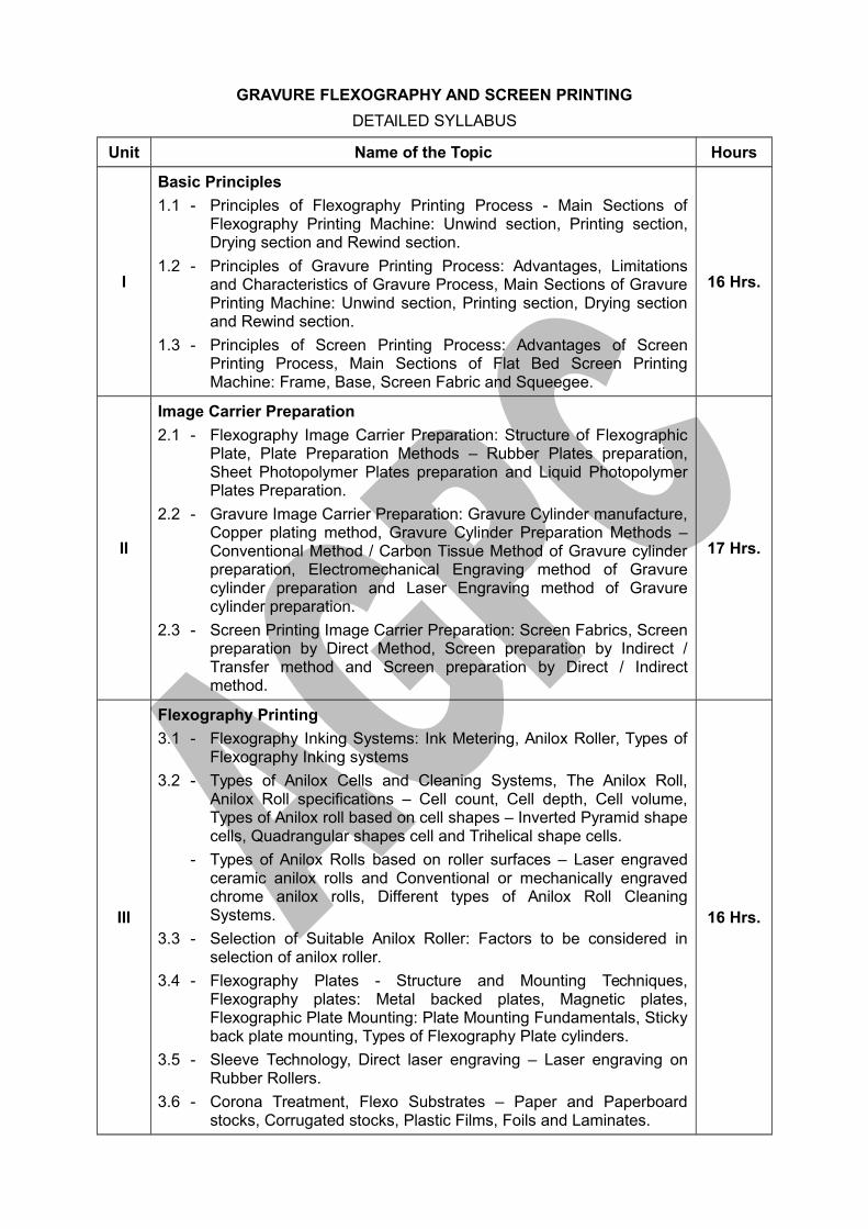
Basic Principles
1.1 - Principles of Flexography Printing Process - Main Sections ofFlexography Printing Machine: Unwind section, Printing section,Drying section and Rewind section.
1.2 - Principles of Gravure Printing Process: Advantages, Limitationsand Characteristics of Gravure Process, Main Sections of GravurePrinting Machine: Unwind section, Printing section, Drying sectionand Rewind section.
1.3 - Principles of Screen Printing Process: Advantages of ScreenPrinting Process, Main Sections of Flat Bed Screen PrintingMachine: Frame, Base, Screen Fabric and Squeegee.
16 Hrs.
II
Image Carrier Preparation
2.1 - Flexography Image Carrier Preparation: Structure of FlexographicPlate, Plate Preparation Methods – Rubber Plates preparation,Sheet Photopolymer Plates preparation and Liquid PhotopolymerPlates Preparation.
2.2 - Gravure Image Carrier Preparation: Gravure Cylinder manufacture,Copper plating method, Gravure Cylinder Preparation Methods –Conventional Method / Carbon Tissue Method of Gravure cylinderpreparation, Electromechanical Engraving method of Gravurecylinder preparation and Laser Engraving method of Gravurecylinder preparation.
2.3 - Screen Printing Image Carrier Preparation: Screen Fabrics, Screenpreparation by Direct Method, Screen preparation by Indirect /Transfer method and Screen preparation by Direct / Indirectmethod.
17 Hrs.
III
Flexography Printing
3.1 - Flexography Inking Systems: Ink Metering, Anilox Roller, Types ofFlexography Inking systems
3.2 - Types of Anilox Cells and Cleaning Systems, The Anilox Roll,Anilox Roll specifications – Cell count, Cell depth, Cell volume,Types of Anilox roll based on cell shapes – Inverted Pyramid shapecells, Quadrangular shapes cell and Trihelical shape cells.
- Types of Anilox Rolls based on roller surfaces – Laser engravedceramic anilox rolls and Conventional or mechanically engravedchrome anilox rolls, Different types of Anilox Roll CleaningSystems.
3.3 - Selection of Suitable Anilox Roller: Factors to be considered inselection of anilox roller.
3.4 - Flexography Plates - Structure and Mounting Techniques,Flexography plates: Metal backed plates, Magnetic plates,Flexographic Plate Mounting: Plate Mounting Fundamentals, Stickyback plate mounting, Types of Flexography Plate cylinders.
3.5 - Sleeve Technology, Direct laser engraving – Laser engraving onRubber Rollers.
3.6 - Corona Treatment, Flexo Substrates – Paper and Paperboardstocks, Corrugated stocks, Plastic Films, Foils and Laminates.
16 Hrs.
Unit Name of the Topic Hours
IV
Gravure Printing
4.1 - Structure of Gravure Cylinder: Gravure cylinder parts – Axis, Shaft,Diameter, Circumference and Face length.
4.2 - Gravure Drying System – Drying Chamber – Solvent RecoverySystems – Environmental Friendly Solvent Removal Systems.
4.3 - Doctor Blade –Structure, Types and Mechanisms of doctor blade.
4.4 - Impression Roller – Structure, Types and Mechanisms ofImpression Roller.
4.5 - Gravure Presses - Gravure Packaging Presses, Gravure LabelPresses and Gravure Publication Presses.
4.6 - Gravure Solvent based inks, Gravure Water based inks, GravureUV and Gravure EB inks.
16 Hrs.
V
Screen Printing
5.1 - Mesh, Squeegee Selection, Mesh / Woven Screen Printing Fabric:Materials used for Screen Printing Fabrics, Squeegee selection:The squeegee, Squeegee selection – Shapes of squeegee blades,Squeegee hardness and Squeegee materials.
5.2 - Screen Pretreatment, Screen Tensioning / Stretching: Basic stepsin Screen Tensioning, Stretching the Screen Printing Fabric –Manual Stretching and Machine Stretching.
5.3 - Types of Screen Printing Machines - Container Screen Printingmachine, Flat bed Hinged frame (Automatic) Screen Press, RotaryScreen Printing Press and Carousal Screen Printing Machines.
5.4 - Screen Printing Inks – Types, Properties, Types of Screen PrintingInks for specific Application
5.5 - Screen Printing Applications: Screen Printing on Flat surfaces andScreen Printing on Curved Surfaces.
15 Hrs.
AGPC, Sivakasi
AGPC, SIVAKASI GRAVURE, FLEXO AND SCREEN PRINTING
UNIT - I – BASIC PRINCIPLES
PRINTING PROCESSES - PRINCIPLES
Lithography, letterpress, flexography, gravure and screen are the major conventional
machine printing processes. Each of these processes is separate and distinct, because of
the different operation of the planographic, relief, intaglio and stencil types of printing.
Image carriers in the form of plates, cylinders or stencils can be created either by
exposing the assembled films onto a light sensitive image area which is then processed, or
by laser engraving, digital or chemical transfer.
All printing image carriers have two separate surfaces - an image or printing area and
a non-image or non-printing area. The image or printing area accepts the ink by mechanical
or chemical means but the non-image area does not accept or retain ink.
1.1.A. PRINCIPLES OF FLEXOGRAPHY PRINTING PROCESS
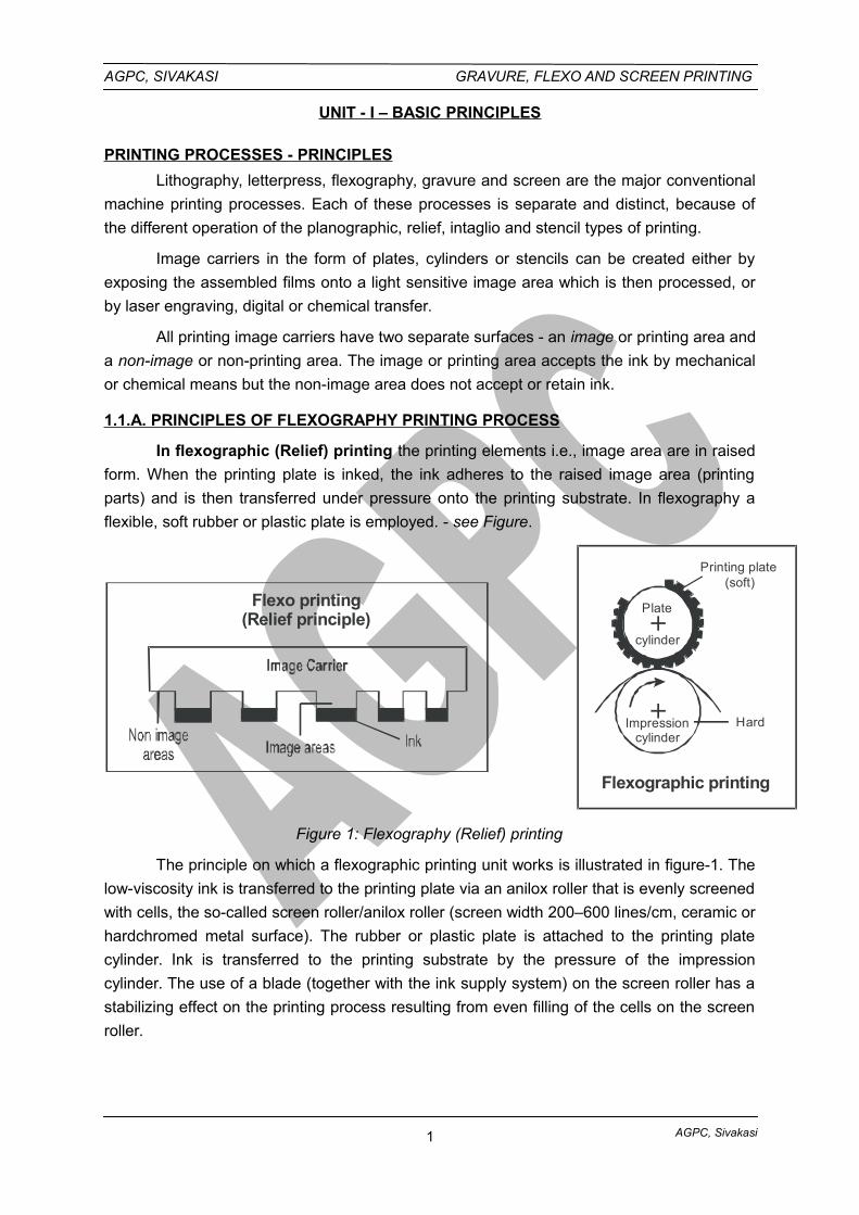
In flexographic (Relief) printing the printing elements i.e., image area are in raised
form. When the printing plate is inked, the ink adheres to the raised image area (printing
parts) and is then transferred under pressure onto the printing substrate. In flexography a
flexible, soft rubber or plastic plate is employed. - see Figure.
Flexo printing(Relief principle)
Flexographic printing
Impressioncylinder
Printing plate(soft)
Hard
cylinder
Plate
Figure 1: Flexography (Relief) printing
The principle on which a flexographic printing unit works is illustrated in figure-1. The
low-viscosity ink is transferred to the printing plate via an anilox roller that is evenly screened
with cells, the so-called screen roller/anilox roller (screen width 200–600 lines/cm, ceramic or
hardchromed metal surface). The rubber or plastic plate is attached to the printing plate
cylinder. Ink is transferred to the printing substrate by the pressure of the impression
cylinder. The use of a blade (together with the ink supply system) on the screen roller has a
stabilizing effect on the printing process resulting from even filling of the cells on the screen
roller.
1
AGPC, Sivakasi
AGPC, SIVAKASI GRAVURE, FLEXO AND SCREEN PRINTING
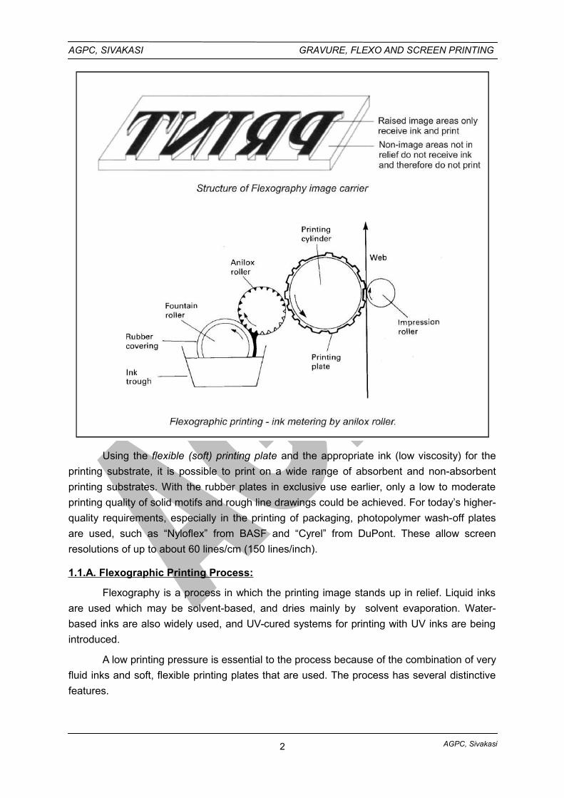
Using the flexible (soft) printing plate and the appropriate ink (low viscosity) for the
printing substrate, it is possible to print on a wide range of absorbent and non-absorbent
printing substrates. With the rubber plates in exclusive use earlier, only a low to moderate
printing quality of solid motifs and rough line drawings could be achieved. For today’s higher-
quality requirements, especially in the printing of packaging, photopolymer wash-off plates
are used, such as “Nyloflex” from BASF and “Cyrel” from DuPont. These allow screen
resolutions of up to about 60 lines/cm (150 lines/inch).
1.1.A. Flexographic Printing Process:
Flexography is a process in which the printing image stands up in relief. Liquid inks
are used which may be solvent-based, and dries mainly by solvent evaporation. Water-
based inks are also widely used, and UV-cured systems for printing with UV inks are being
introduced.
A low printing pressure is essential to the process because of the combination of very
fluid inks and soft, flexible printing plates that are used. The process has several distinctive
features.
2
AGPC, Sivakasi
AGPC, SIVAKASI GRAVURE, FLEXO AND SCREEN PRINTING
Liquid inks are used that dry rapidly by solvent evaporation, thus enabling fast
printing speeds to be achieved on non-absorbent materials such as films and
foils.
‘Soft’ and flexible relief printing plates are employed that can be mounted and
registered on a plate cylinder and proofs can also be obtained. Individual plates
can easily be changed or rectified, and a portion of a plate can be removed to
enable items such as price or expiry date to be changed.
The application of ink to the surface of the printing plate is by means of a
screened (Anilox) roller. The result is a simple ink feed system that consists of
not more than two rollers, or perhaps a single roller and doctor blade (s).
Although most flexographic printing is roll to roll, the machines enable changes
in the print repeat length to be made simply.
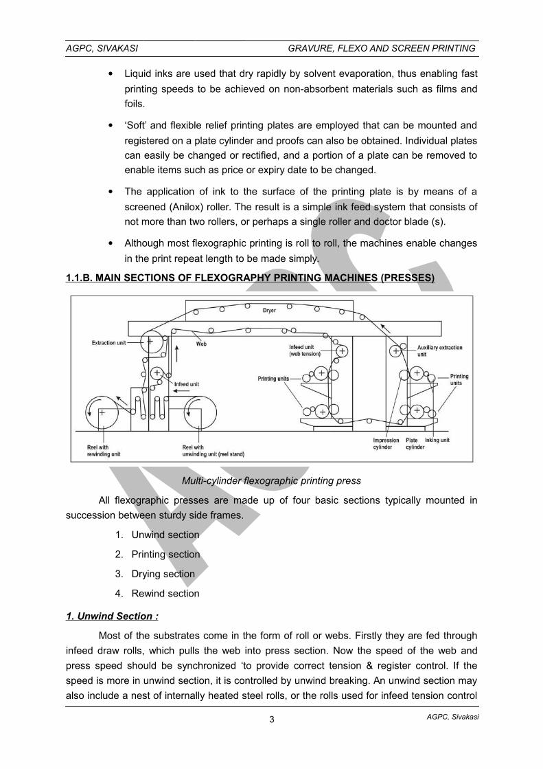
1.1.B. MAIN SECTIONS OF FLEXOGRAPHY PRINTING MACHINES (PRESSES)
Multi-cylinder flexographic printing press
All flexographic presses are made up of four basic sections typically mounted in
succession between sturdy side frames.
1. Unwind section
2. Printing section
3. Drying section
4. Rewind section
1. Unwind Section :
Most of the substrates come in the form of roll or webs. Firstly they are fed through
infeed draw rolls, which pulls the web into press section. Now the speed of the web and
press speed should be synchronized ‘to provide correct tension & register control. If the
speed is more in unwind section, it is controlled by unwind breaking. An unwind section may
also include a nest of internally heated steel rolls, or the rolls used for infeed tension control
3
AGPC, Sivakasi
AGPC, SIVAKASI GRAVURE, FLEXO AND SCREEN PRINTING
may be heated for a secondary purpose. This purpose is to ‘open’ the surface of heavily
glazed or ‘tight’ papers by preheating, thus rendering the surface more receptive to printing
ink. Preheating in this manner is also beneficial with some plastic materials, as it ‘normalizes’
the web, making it flatter and reducing the tendency to wrinkle.
2. Printing Section:
A single color station with the four essential rolls are fountain roller, inking roller,
printing plate cylinder and impression cylinder - is sufficient to constitute a press. The
majority of printing presses are multi-colour; from two to eight colors in printing section. In
some presses these color units are arranged horizontally, in-line, similar to a rotogravure
press. Much over common is an arrangement, unique of flexography, in one or more
‘stacks’with a single stack of two to four color units, each color unit arranged vertically one
above another. An arrangement of color units similar to a rotary letterpress, around a single,
large, common impression cylinder is also common. This arrangement is called a central
impression (CI) press.
The printing unit consists of the following three basic parts:
a. Inking unit
b. Plate cylinder
c. Impression cylinder
a. Inking Unit:
The function of the inking system is to meter out a fine and controlled film of liquid
ink, and apply this to the surface of the printing plate.
It typically consists of an ink trough, a rubber-covered fountain roller, and a screened
(Anilox) inking roller into which cells of uniform size and depth are engraved. The fountain
roller lifts ink to the nip position, where it is squeezed into the cells in the screened inking
roller and by a shearing action, ink is removed from the roller surface. The ink in the cells is
then transferred to the surface of the printing plates. To regulate ink film thickness in printing,
screened ink (anilox) rollers are available which have screens ranging from 40 to 200
cells/cm. These may be engraved or etched on metal or ceramic. The engraved cells are
generally square in shape (although many other shapes are available now) with sloping side
walls.
When printing halftones, the cells per centimetre of the anilox roller needs to be
about 3.5 times the halftone screen ruling. The number of cells and their size regulate the
volume of ink transferred. Further regulation of the ink is achieved by varying the surface
speed of the fountain roller, by altering the pressure between the fountain roller and
screened roller, and also by altering the hardness of the rubber covering on the fountain
roller. Despite these controllable factors it is still the basic characteristic of the anilox roller
which determines the ink supply to the plate. The anilox roller is a crucial factor in achieving
good-quality flexo printing.
4
AGPC, Sivakasi
AGPC, SIVAKASI GRAVURE, FLEXO AND SCREEN PRINTING
b. Plate Cylinder:
The plate cylinder is usually made from steel. The printing plates, which have a
thickness of up to a few millimetres are secured to the cylinder with double-sided self-
adhesive material.
c. Impression Cylinder :
The impression cylinder is also made from steel. The substrate passes between the
plate and impression cylinders, which generate light printing pressure. The ink is transferred
from the cells in the screened ink roller to the plate surface, and then to the substrate, during
which it reaches virtually a uniform film.
For high-quality flexographic printing the components of the printing unit must be
engineered to very tight tolerances (measured in tenths of thousandths of an inch). The
ability to manufacture to these standards is one of the factors which has contributed to the
growth of flexographic printing to produce higher-quality products.
3. Drying Section :
The Drying section require an after-drier to remove the remaining solvent from all the
colours before the web can be wound in to a roll. The drying section may also require
between printing units on multi color presses to permit the necessary printing of color on
color. The removal of solvents can be accomplished in several ways, hot air drier is the most
common. However revolutionary method of drying are being investigated.
An exhaust system conjunction with the after dryer prevents a build of solvent laden
air that might become an explosive hazard. In between color hot air dryers it is essential that
the exhaust exist the warm air supply, otherwise the location of these dryers in the very
minimal space between color units would result in warm air being blown on to the inking
rollers and plate cylinders. Premature ink drying would seriously interfere with the inking of
the plates and printing of their image on to the web.
4. Rewind Section :
This section is identical to the unwind section in most respects but with some
significant differences. It need to be nothing more than a shaft in plain bearings holding the
winding roll by means of core chucks. However, there is one important difference. The
unwind shaft is braked to add necessary tension as the press pulls the web off the roll. The
rewind shaft must be driven.
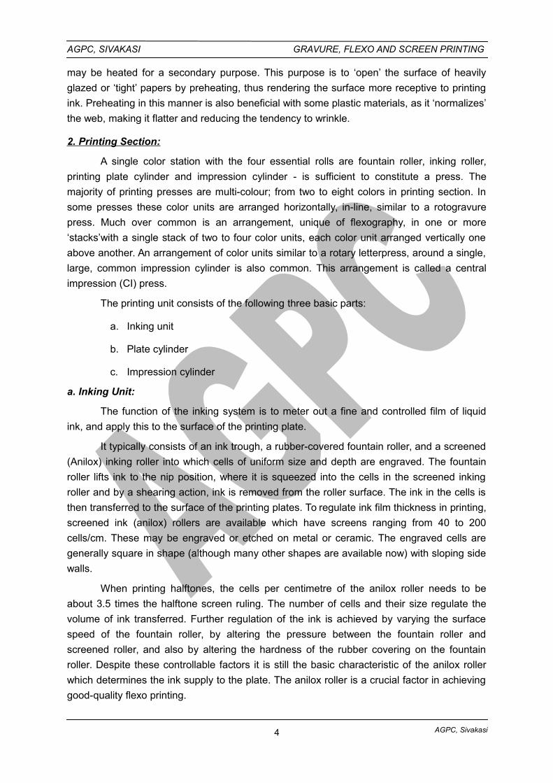
1.2.A. PRINCIPLES OF GRAVURE PRINTING PROCESS
In this type of printing, the printing areas are in recess - that is, on a lower level than
the non-printing surface. The recesses are filled with ink and surplus ink is removed from the
non-printing surface by doctor blade. The substrate is then pressed against the printing
cylinder to transfer the ink onto it - see Figure. The main examples of gravure printing are
Rotogravure printing and, in the area of arts and crafts, copper plate engraving and die-
stamping (also security printing).
5
AGPC, Sivakasi
AGPC, SIVAKASI GRAVURE, FLEXO AND SCREEN PRINTING
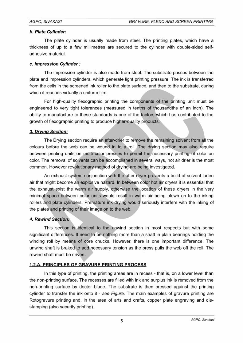
Gravure is the process which uses the intaglio principle. The shortest ink train is
found in the gravure process as the gravure cylinder actually revolves in a bath of ink. The
doctor blade removes excess ink, but leaves ink in the thousands of engraved cells in the
copper cylinder.
Figure: Gravure printing
The distinctive feature of gravure printing technology is the fact that the image
elements are engraved into the surface of the cylinder. The non-image areas are at a
constant, original level. Prior to printing, the entire printing plate (non-printing and printing
elements) is inked and flooded with ink. Ink is removed from the non-image (by a wiper or
blade) before printing, so that ink remains only in the cells. The ink is transferred from the
cells to the printing substrate by a high printing pressure and the adhesive forces between
printing substrate and ink.
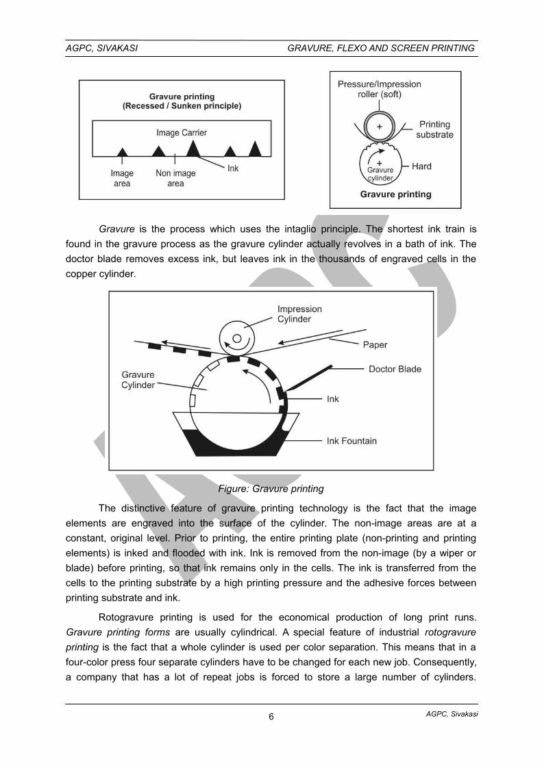
Rotogravure printing is used for the economical production of long print runs.
Gravure printing forms are usually cylindrical. A special feature of industrial rotogravure
printing is the fact that a whole cylinder is used per color separation. This means that in a
four-color press four separate cylinders have to be changed for each new job. Consequently,
a company that has a lot of repeat jobs is forced to store a large number of cylinders.
6
AGPC, Sivakasi
AGPC, SIVAKASI GRAVURE, FLEXO AND SCREEN PRINTING
Depending on the printing format, gravure printing cylinders are generally rather heavy and
require special conveying and handling gear systems.
Figure: Two-colour Rotogravure press
1.2.A. INTAGLIO / GRAVURE PROCESS
In this process a metal plate usually copper is used as a image carrier. Here, copper
etching or hand engraving is carried out to form an image. Ink is applied over the image
areas, excess inks are wiped off. A sheet is laid over the plate and pressure is applied. Ink
from recessed area is transferred to paper according to the width and depth of engraved
lines.
Photogravure:
Photogravure is an intaglio process. Image areas are deeply etched below the
surface of the copperised surface of printing cylinder. Liquid ink is filled in the recessed
image areas and a doctor blade wipes the surface clean free from surplus ink. The cylinder
is pressed on paper or other material for transferring the inked image.
Gravure Printing:
Gravure is the photographic version of the original “Intaglio” process and Gravure is a
process which follows the intaglio principle.
In Gravure process, the printing image is engraved into a cylinder in the form of cells.
The engraved cells are filled with ink and excess ink on the cylinder surface is wiped off by
7
AGPC, Sivakasi
AGPC, SIVAKASI GRAVURE, FLEXO AND SCREEN PRINTING
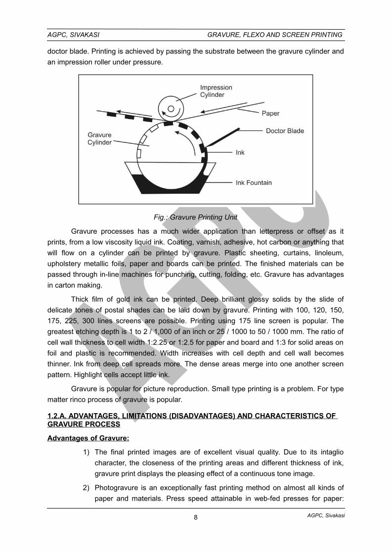
doctor blade. Printing is achieved by passing the substrate between the gravure cylinder and
an impression roller under pressure.
Fig.: Gravure Printing Unit
Gravure processes has a much wider application than letterpress or offset as it
prints, from a low viscosity liquid ink. Coating, varnish, adhesive, hot carbon or anything that
will flow on a cylinder can be printed by gravure. Plastic sheeting, curtains, linoleum,
upholstery metallic foils, paper and boards can be printed. The finished materials can be
passed through in-line machines for punching, cutting, folding, etc. Gravure has advantages
in carton making.
Thick film of gold ink can be printed. Deep brilliant glossy solids by the slide of
delicate tones of postal shades can be laid down by gravure. Printing with 100, 120, 150,
175, 225, 300 lines screens are possible. Printing using 175 line screen is popular. The
greatest etching depth is 1 to 2 / 1,000 of an inch or 25 / 1000 to 50 / 1000 mm. The ratio of
cell wall thickness to cell width 1:2.25 or 1:2.5 for paper and board and 1:3 for solid areas on
foil and plastic is recommended. Width increases with cell depth and cell wall becomes
thinner. Ink from deep cell spreads more. The dense areas merge into one another screen
pattern. Highlight cells accept little ink.
Gravure is popular for picture reproduction. Small type printing is a problem. For type
matter rinco process of gravure is popular.
1.2.A. ADVANTAGES, LIMITATIONS (DISADVANTAGES) AND CHARACTERISTICS OF GRAVURE PROCESS
Advantages of Gravure:
1) The final printed images are of excellent visual quality. Due to its intaglio
character, the closeness of the printing areas and different thickness of ink,
gravure print displays the pleasing effect of a continuous tone image.
2) Photogravure is an exceptionally fast printing method on almost all kinds of
paper and materials. Press speed attainable in web-fed presses for paper:
8
AGPC, Sivakasi
AGPC, SIVAKASI GRAVURE, FLEXO AND SCREEN PRINTING
1,000 fpm (Feet Per Minute) ; Film and Foil: 300 to 600 fpm. Sheet-fed
presses: 3000 sheets per hour.
3) The printed sheet is usually dried, when it leaves the press, due to the
volatility of the fluid ink.
4) Gravure cylinders yield very large number of impressions and under proper
handling even yield several millions copies. Chrome-plated copper cylinder
can print 1.5 million revolutions without re-chroming; and can print 12 to 20
million revolutions before making new cylinders, depending on material
printed.
5) Rotogravure ink, based on, fluid ink can be formulated for printing on a,
variety of printing stocks - paper, paperboard, plastic films, metal foils,
textiles, etc.
6) The supplementary operations like cutting, punching, creasing and stripping
are done “Inline”, the end product are fabricated at the same speed at which
printing press runs.
7) Cheaper paper stock can be used on gravure presses compared with other
processes.
8) Quality reproductions at low cost is possible.
9) Large presses with a web width of 144inch are used for printing of vinyl floor
covering.
10) Virtually, there is no make-ready involved while printing on a Gravure press.
Limitations of Gravure :
1) Length of time to prepare and etch a cylinder. Generally, it required between
three and four hours from the time resist has been applied to the copper
surface until the printing form is ready to be proofed.
2) The high initial cost incurred in the cylinder preparation.
3) Type, Text matter and fine line illustrations do not reproduce as sharply in
gravure as it is reproduced in offset chiefly because the rotogravure screen
gives a “sawtooth” edge to vertical lines and horizontal lines while using
gravure screens.
4) Minimum economical run is said to be 50,000 copies.
5) Once the cylinder has been prepared, very limited alterations or revisions
alone can be made without having to prepare a new cylinder.
6) Air conditioning of the plant is necessary due to the inherent nature of the
process.
Characteristics :
1) All gravure text matter as well as pictures must be screened.
9
AGPC, Sivakasi
AGPC, SIVAKASI GRAVURE, FLEXO AND SCREEN PRINTING
2) Generally the gravure cylinder itself is etched and acts as the image carrier.
3) Gravure prints from a design below the surface of the plate or cylinder.
4) Gradations of tone are obtained by etched cells to different depths, so that
more or less ink is carried by the cells and transferred to the paper according
to their depth.
5) The use of the “Doctor blade” in the printing press (to remove ink from non-
printing areas).
6) An interesting possibility of gravure press is the fact that a simple basic
principle allows the use of cylinders of different diameters, without complicate
changes in the unit gearings.
7) A continuous tone positive is used for exposing on the carbon tissue.
1.2.B. MAIN SECTIONS OF GRAVURE PRINTING MACHINE:
All gravure machines consist of following main sections:
1) Unwind section
2) Printing section
3) Drying section
4) Rewind section
1. Unwind Section :
Most of the substrates come in the form of roll or web. First web is fed through infeeddraw rolls, which pulls the web into press section. Now the speed of the web and pressspeed should be synchronized to provide correct tension & register control. If the speed ismore in unwind section, it is controlled by unwind breaking. An unwind section may alsoinclude a nest of internally heated steel rolls, or the rolls used for infeed tension control maybe heated for a secondary purpose. This purpose is to ‘open’ the surface of heavily glazed or‘tight’ papers by preheating, thus rendering the surface more receptive to printing ink.Preheating in this manner is also beneficial with some plastic materials, as it ‘normalizes’ theweb, making it flatter and reducing the tendency to wrinkle.
2. Printing Section :
The printing unit of gravure machine consist of following :
a) Ink duct
b) Printing cylinder
c) Doctor blade
d) Impression cylinder
a. Ink Duct
In olden days open ink trough was used. There is no control of solvent evaporationand ink is not well agitated, it was unsuitable for high speed machines. Where there is apump which continuously agitate the ink and pump it to the ink trough in which printingcylinder rotates. Excess ink is returned back to the tank from ink trough.
10
AGPC, Sivakasi
AGPC, SIVAKASI GRAVURE, FLEXO AND SCREEN PRINTING
Due to this enclosed system solvent evaporation is reduced. This enclosed systemalso employs viscosity control of the ink. In this system whenever the ink is returned from inktrough, it is filtered and solvent is added to maintain the viscosity of ink.
Further to this enclosed inking system a spray system is also used for very highspeed machines, where ink pump delivers the ink to nozzles pointing at the cylinder. Thenozzle surface is always kept wet. It will never dry out. This system also fully enclosed.
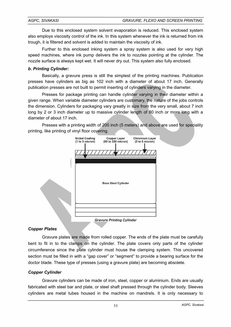
b. Printing Cylinder:
Basically, a gravure press is still the simplest of the printing machines. Publicationpresses have cylinders as big as 102 inch with a diameter of about 17 inch. Generallypublication presses are not built to permit inserting of cylinders varying in the diameter.
Presses for package printing can handle cylinder varying in their diameter within agiven range. When variable diameter cylinders are customary, the nature of the jobs controlsthe dimension. Cylinders for packaging vary greatly in size from the very small, about 7 inchlong by 2 or 3 inch diameter up to massive cylinder length of 80 inch or more long with adiameter of about 17 inch.
Presses with a printing width of 200 inch (5 meters) and above are used for specialityprinting, like printing of vinyl floor covering.
Copper Plates
Gravure plates are made from rolled copper. The ends of the plate must be carefully
bent to fit in to the clamps on the cylinder. The plate covers only parts of the cylinder
circumference since the plate cylinder must house the clamping system. This uncovered
section must be filled in with a “gap cover” or “segment” to provide a bearing surface for the
doctor blade. These type of presses (using a gravure plate) are becoming absolete.
Copper Cylinder
Gravure cylinders can be made of iron, steel, copper or aluminium. Ends are usually
fabricated with steel bar and plate, or steel shaft pressed through the cylinder body. Sleeves
cylinders are metal tubes housed in the machine on mandrels. It is only necessary to
11
AGPC, Sivakasi
AGPC, SIVAKASI GRAVURE, FLEXO AND SCREEN PRINTING
produce a sleeve or tube with this system, for subsequent mounting on a machine mandrel.
The sleeve is generally made of steel base and deposited with copper, to a diameter slightly
larger than the required size. It is then turned and polished in a lath to obtain the correct
diameter and perfect stage. This system is not recommended for multi-unit web-fed presses
and for large-run package printing.
In the Ballard process, a thin skin deposit of copper is loosely adhered to the bulk of
the cylinder surface, but is firmly attached at the bar ends. After printing, the copper skin is
removed by cutting and then pulling off. The advantages of Ballard process are elimination
of grinding of the old etching and allowing exact size cylinders for color works. The thin film
of copper is approximately 0.006 inch thick and is deposited in about one and a half hours.
This type of cylinder is used for printing of short-run magazine and packing. On an average,
to deposit one square foot of copper for 0.001 inch thick, the requirements of copper is 0.74
oz.
Solid cylinders are invariably used on web-fed presses. The thickness of the copper
deposit varies depending upon the circumference, length and construction of the cylinder.
The copper deposit ranges from 0.015 to 0.050 inch thick, and copper is deposited slightly
more than the required thickness. Afterwards the cylinder is taken out and brought to the
required diameter by turning it on a lathe and then it is polished to a high luster. The
accuracy of the cylinder is maintained within a tolerance of + or – 0.0005 inch.
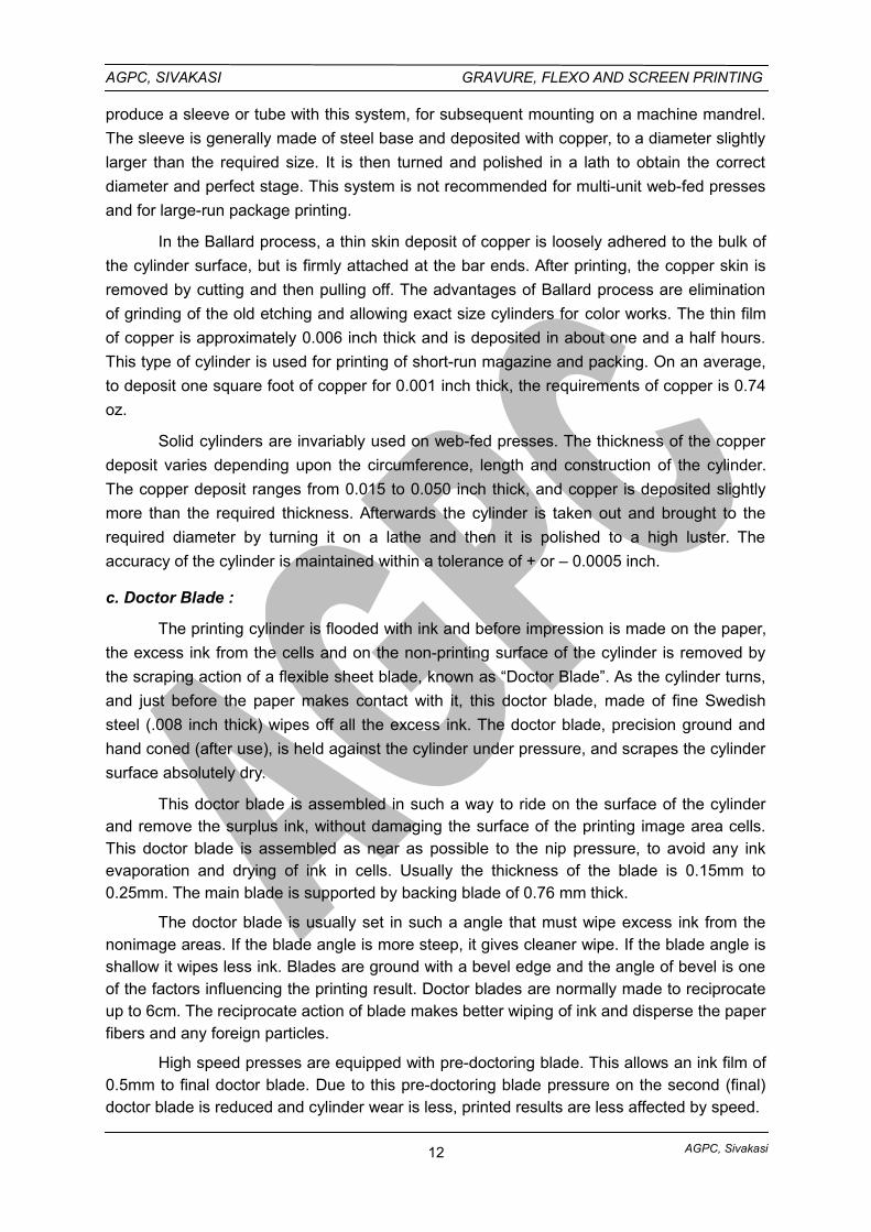
c. Doctor Blade :
The printing cylinder is flooded with ink and before impression is made on the paper,
the excess ink from the cells and on the non-printing surface of the cylinder is removed by
the scraping action of a flexible sheet blade, known as “Doctor Blade”. As the cylinder turns,
and just before the paper makes contact with it, this doctor blade, made of fine Swedish
steel (.008 inch thick) wipes off all the excess ink. The doctor blade, precision ground and
hand coned (after use), is held against the cylinder under pressure, and scrapes the cylinder
surface absolutely dry.
This doctor blade is assembled in such a way to ride on the surface of the cylinderand remove the surplus ink, without damaging the surface of the printing image area cells.This doctor blade is assembled as near as possible to the nip pressure, to avoid any inkevaporation and drying of ink in cells. Usually the thickness of the blade is 0.15mm to0.25mm. The main blade is supported by backing blade of 0.76 mm thick.
The doctor blade is usually set in such a angle that must wipe excess ink from thenonimage areas. If the blade angle is more steep, it gives cleaner wipe. If the blade angle isshallow it wipes less ink. Blades are ground with a bevel edge and the angle of bevel is oneof the factors influencing the printing result. Doctor blades are normally made to reciprocateup to 6cm. The reciprocate action of blade makes better wiping of ink and disperse the paperfibers and any foreign particles.
High speed presses are equipped with pre-doctoring blade. This allows an ink film of0.5mm to final doctor blade. Due to this pre-doctoring blade pressure on the second (final)doctor blade is reduced and cylinder wear is less, printed results are less affected by speed.
12
AGPC, Sivakasi
AGPC, SIVAKASI GRAVURE, FLEXO AND SCREEN PRINTING
d. Impression Roller:
This has a steel core with hard rubber covering to bear the heavy pressure. The
rubber covering is of 12 to 20 mm thickness. Its hardness is from 60o to 100o shore. If thesubstrate is too rough and more compressible then hard rubber is used. Plastic films arenormally printed with soft roll and with low impression pressure.
In general the pressure applied between impression roller and printing cylinder ishigher than any other processes. The impression roller is oftenly supported with third rollercalled “BACK UP” to overcome the impression roller deflection and give sufficient pressurein the center. Another technique is “flexible” roll which can be adjusted to even out thepressure across the width of the web.
Now a days impression rollers are employed with electrostatically assisted inktransfer. To overcome the printing problem “speckle” (individual cells not printing on roughpapers and noncompressible papers even if it is coated one). In this special roller during theturning (rotation) high voltage is generated. This electric field encourages the ink to leave thecells and transfer to the paper even the contact is imperfect.
3. Drying Section :
The Drying section require an after-drier to remove the remaining solvent from all thecolours before the web can be wound in to a roll. The drying section may also requirebetween printing units on multi color presses to permit the necessary printing of color oncolor. The removal of solvents can be accomplished in several ways, hot air driers being themost common.
An exhaust system conjunction with the after dryer prevents a build of solvent ladenair that might become an explosive hazard. In between color hot air dryers it is essential thatthe exhaust exist the warm air supply, otherwise the location of these dryers in the veryminimal space between color units would result in warm air being blown on to the inkingrollers and plate cylinders. Premature ink drying would seriously interfere with the inking ofthe plates and printing of their image on to the web.
4. Rewind Section :
This section is identical to the unwind section in most respects but with somesignificant differences. It need be nothing more than a shaft in plain bearings holding thewinding roll by means of core chucks. However, there is one important difference. Theunwind shaft is braked to add necessary tension as the press pulls the web off the roll. Therewind shaft must be driven.
13
AGPC, Sivakasi
AGPC, SIVAKASI GRAVURE, FLEXO AND SCREEN PRINTING
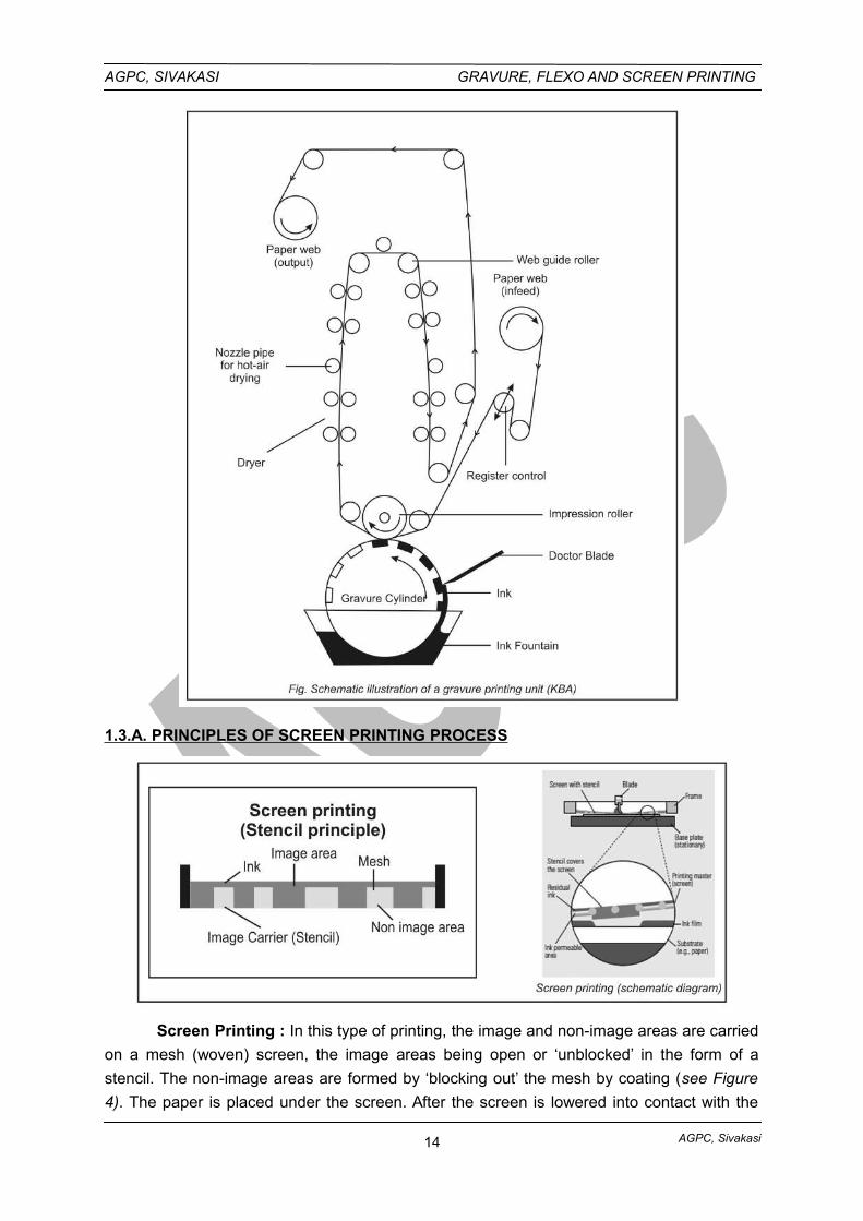
1.3.A. PRINCIPLES OF SCREEN PRINTING PROCESS
Screen Printing : In this type of printing, the image and non-image areas are carried
on a mesh (woven) screen, the image areas being open or ‘unblocked’ in the form of a
stencil. The non-image areas are formed by ‘blocking out’ the mesh by coating (see Figure
4). The paper is placed under the screen. After the screen is lowered into contact with the
14
AGPC, Sivakasi
AGPC, SIVAKASI GRAVURE, FLEXO AND SCREEN PRINTING
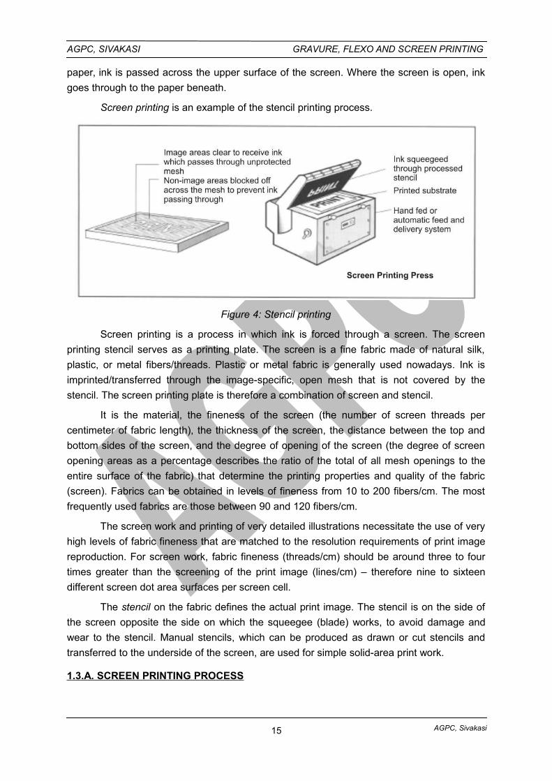
paper, ink is passed across the upper surface of the screen. Where the screen is open, ink
goes through to the paper beneath.
Screen printing is an example of the stencil printing process.
Figure 4: Stencil printing
Screen printing is a process in which ink is forced through a screen. The screen
printing stencil serves as a printing plate. The screen is a fine fabric made of natural silk,
plastic, or metal fibers/threads. Plastic or metal fabric is generally used nowadays. Ink is
imprinted/transferred through the image-specific, open mesh that is not covered by the
stencil. The screen printing plate is therefore a combination of screen and stencil.
It is the material, the fineness of the screen (the number of screen threads per
centimeter of fabric length), the thickness of the screen, the distance between the top and
bottom sides of the screen, and the degree of opening of the screen (the degree of screen
opening areas as a percentage describes the ratio of the total of all mesh openings to the
entire surface of the fabric) that determine the printing properties and quality of the fabric
(screen). Fabrics can be obtained in levels of fineness from 10 to 200 fibers/cm. The most
frequently used fabrics are those between 90 and 120 fibers/cm.
The screen work and printing of very detailed illustrations necessitate the use of very
high levels of fabric fineness that are matched to the resolution requirements of print image
reproduction. For screen work, fabric fineness (threads/cm) should be around three to four
times greater than the screening of the print image (lines/cm) – therefore nine to sixteen
different screen dot area surfaces per screen cell.
The stencil on the fabric defines the actual print image. The stencil is on the side of
the screen opposite the side on which the squeegee (blade) works, to avoid damage and
wear to the stencil. Manual stencils, which can be produced as drawn or cut stencils and
transferred to the underside of the screen, are used for simple solid-area print work.
1.3.A. SCREEN PRINTING PROCESS
15
AGPC, Sivakasi
AGPC, SIVAKASI GRAVURE, FLEXO AND SCREEN PRINTING
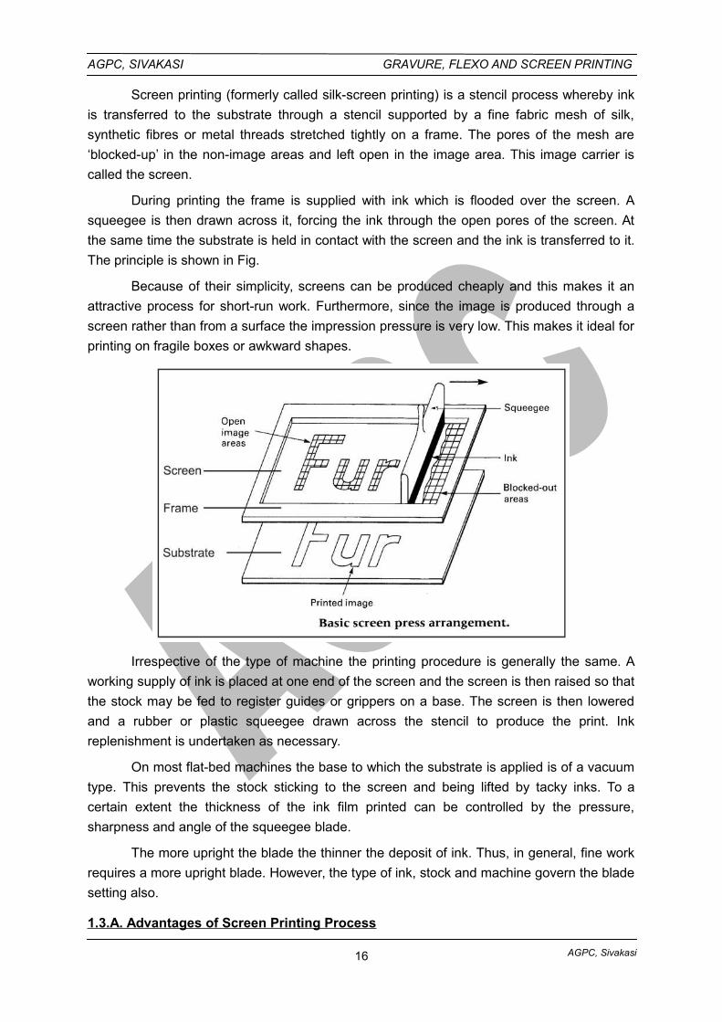
Screen printing (formerly called silk-screen printing) is a stencil process whereby ink
is transferred to the substrate through a stencil supported by a fine fabric mesh of silk,
synthetic fibres or metal threads stretched tightly on a frame. The pores of the mesh are
‘blocked-up’ in the non-image areas and left open in the image area. This image carrier is
called the screen.
During printing the frame is supplied with ink which is flooded over the screen. A
squeegee is then drawn across it, forcing the ink through the open pores of the screen. At
the same time the substrate is held in contact with the screen and the ink is transferred to it.
The principle is shown in Fig.
Because of their simplicity, screens can be produced cheaply and this makes it an
attractive process for short-run work. Furthermore, since the image is produced through a
screen rather than from a surface the impression pressure is very low. This makes it ideal for
printing on fragile boxes or awkward shapes.
Irrespective of the type of machine the printing procedure is generally the same. A
working supply of ink is placed at one end of the screen and the screen is then raised so that
the stock may be fed to register guides or grippers on a base. The screen is then lowered
and a rubber or plastic squeegee drawn across the stencil to produce the print. Ink
replenishment is undertaken as necessary.
On most flat-bed machines the base to which the substrate is applied is of a vacuum
type. This prevents the stock sticking to the screen and being lifted by tacky inks. To a
certain extent the thickness of the ink film printed can be controlled by the pressure,
sharpness and angle of the squeegee blade.
The more upright the blade the thinner the deposit of ink. Thus, in general, fine work
requires a more upright blade. However, the type of ink, stock and machine govern the blade
setting also.
1.3.A. Advantages of Screen Printing Process
16
AGPC, Sivakasi
AGPC, SIVAKASI GRAVURE, FLEXO AND SCREEN PRINTING
One of the major advantages of the screen process is the ability to obtain prints on
non-flat objects. For example, printing on bottles or other cylindrical objects is achieved by
using a press of the cylinder type described above but the object to be printed is placed in
the machine where the impression cylinder is shown. After each impression the bottle is
removed and another unprinted one substituted. There are few limitations on size or shape.
Special screens and jigs are produced for printing on shaped objects such as cups with
handles or tapering cylinders, and screens with high elasticity combined with shaped
squeegees are used for conforming to irregular objects. Print heads can also be bolted to
automatic production lines, so that printing becomes a part of the total production process of
such objects as filled polythene bottles.
1.3.A. APPLICATIONS OF SCREEN PRINTING
i. Screen Printing on Flat Surfaces
Posters and Graphics Printing in Short Print Runs.
Large-format posters in particular can be produced relatively conveniently in fairly
small print runs. The quite thick ink film produces coloring that is very brilliant and resistant
even with halftone color impressions.
Traffic Routing Systems and Signs. Large printing surfaces for high resistance inks
are found with traffic signs and routing systems. The requirements they impose are best met
using screen printing.
Vehicle Fittings and Instrument Dials. With vehicle fittings a narrow tolerance
range of the translucency of the impression is required in addition to its precision. For
example, it must be possible for control lights to light up in precisely defined colors.
Printed Circuit Boards for Electronics. Due to its simplicity and flexibility, screen
printing is an important process during the development of printed circuit boards for
electronic circuits. Accurate printing onto copper-laminated hard paper or glass-fiber
reinforced epoxy board with etching allowance, solder resist, or assembly designations in the
necessary coating thickness is only possible in large quantities with screen printing.
Restrictions are, however, imposed on the latter as a result of the extreme miniaturization of
components and printed circuit boards.
Photovoltaic. Special conductive pastes are used to print on photo resistors and
solar cells, which serve as the contact points for current transfer. In doing so, particular
importance is placed on high coating thickness in areas that are, at the same time, extremely
small and covered with printed conductors, in order to optimize the efficiency of the energy
production with the solar cells as fully as possible.
Compact Discs (CD). Screen printing is one of the major processes for printing on
CDs. Pad printing and more recently even offset printing are also used.
Textiles. The depth of the ink absorption in textiles calls for a large volume of ink to
be supplied and screen printing is the preferable process for applying it. Clothing, canvas
17
AGPC, Sivakasi
AGPC, SIVAKASI GRAVURE, FLEXO AND SCREEN PRINTING
shopping bags, webs of material, and so on, can be printed in both flatbed and rotary screen
printing.
Transfer Images. Screen printing is frequently used to produce transfer images for
ceramic decoration. These images are put together from ceramic pigments for firing. The
pigment’s grain size necessitates the use of a screen mesh that is not too fine. After
detachment the images are removed from the base material and placed on the preburned
bodies by hand. A recognizable feature of these ceramic products is the thick layer of ink.
The images can be placed above or below the glazing.
Decorative Products, Labels, Wallpapers. Seamless decorations such as textile
webs, wallpaper, and other decorative products, as well as labels often require rotary printing
combined with reel material. Special machines are designed for this. Rotary screen printing
with sheet material is used primarily for higher print runs.
Surface Finishing. Transparent varnish can also be applied using screen printing
technology (for spot varnishing, in particular) to finish the printed product as add on value to
attract the customers.
ii. Screen Printing on Curved Surfaces
Almost any body that has an even, convex and concave (to a limited extent) not too
structured surface can be printed using screen printing. There are virtually no restrictions
with regard to the material of the body to be printed on. Ceramics can be printed directly with
screen printing. Ceramic pigment inks can be used for subsequent baking or just a low
durability varnish applied to the glazed product. It is not always possible to print directly onto
plastic components. Surface treatment, for example involving flame treatment, corona
charging, or the application of primer is often necessary to ensure that the ink adheres.
Bottles. Glass bottles with a baked finish or pretreated plastic bottles for the food
and domestic products sector are printed using the screen printing process.
Toys.Toys, such as balls, and so forth, can be printed in full in several operational
steps.
Glasses. The screen printing process is often used for drinking glass decoration,
with thick coatings of all inks and also gold being applied.
Advertising Media. The type of advertising medium that can be decorated or
provided with some other overprinting by the screen printing process ranges from cigarette
lighters or ballpoint pens to pocket knives and pocket calculators.
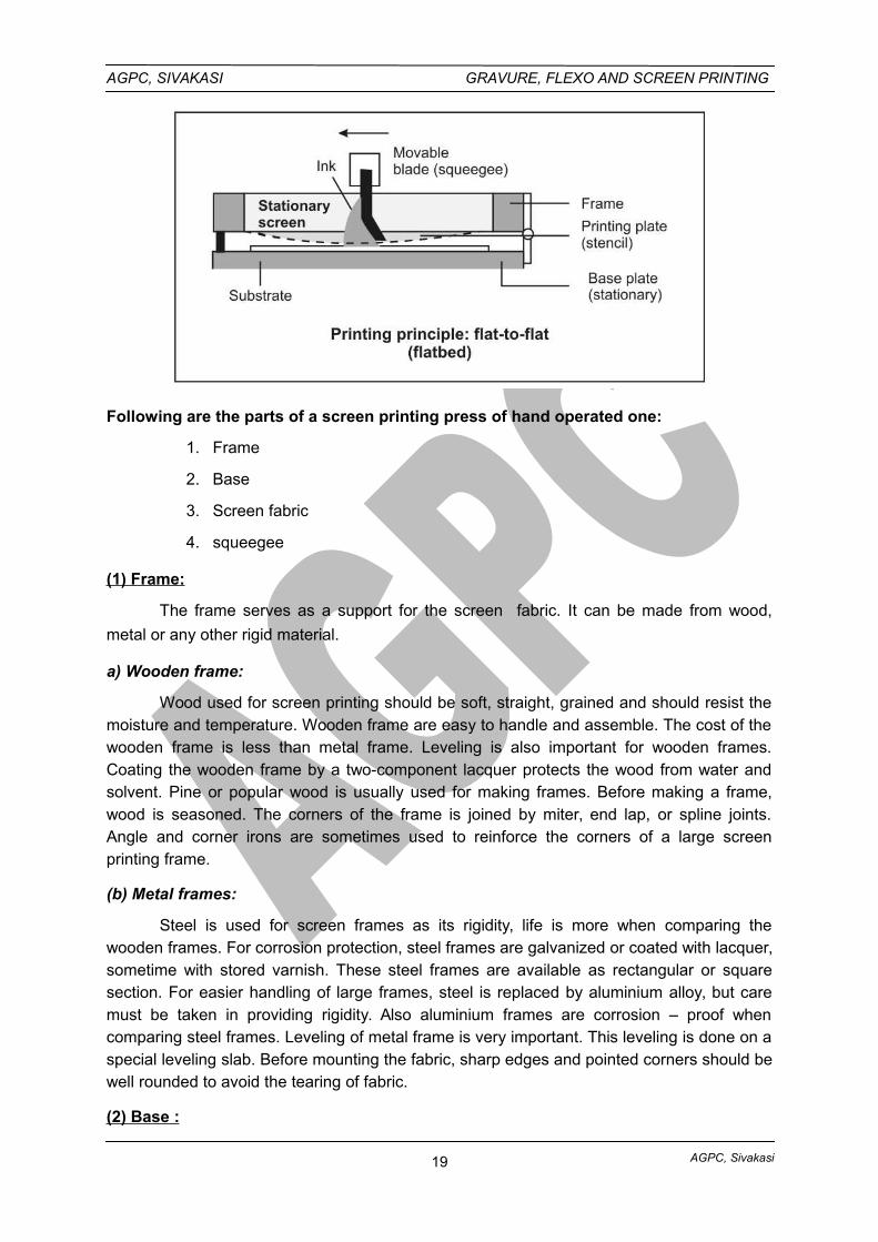
1.3.B. MAIN SECTIONS OF A FLATBED SCREEN PRINTING MACHINE
18
AGPC, Sivakasi
AGPC, SIVAKASI GRAVURE, FLEXO AND SCREEN PRINTING
Following are the parts of a screen printing press of hand operated one:
1. Frame
2. Base
3. Screen fabric
4. squeegee
(1) Frame:
The frame serves as a support for the screen fabric. It can be made from wood,
metal or any other rigid material.
a) Wooden frame:
Wood used for screen printing should be soft, straight, grained and should resist themoisture and temperature. Wooden frame are easy to handle and assemble. The cost of thewooden frame is less than metal frame. Leveling is also important for wooden frames.Coating the wooden frame by a two-component lacquer protects the wood from water andsolvent. Pine or popular wood is usually used for making frames. Before making a frame,wood is seasoned. The corners of the frame is joined by miter, end lap, or spline joints.Angle and corner irons are sometimes used to reinforce the corners of a large screenprinting frame.
(b) Metal frames:
Steel is used for screen frames as its rigidity, life is more when comparing thewooden frames. For corrosion protection, steel frames are galvanized or coated with lacquer,sometime with stored varnish. These steel frames are available as rectangular or squaresection. For easier handling of large frames, steel is replaced by aluminium alloy, but caremust be taken in providing rigidity. Also aluminium frames are corrosion – proof whencomparing steel frames. Leveling of metal frame is very important. This leveling is done on aspecial leveling slab. Before mounting the fabric, sharp edges and pointed corners should bewell rounded to avoid the tearing of fabric.
(2) Base :
19
AGPC, Sivakasi
AGPC, SIVAKASI GRAVURE, FLEXO AND SCREEN PRINTING
This is the surface upon which the substrate to be printed is positioned and held. It is
usually made from a thin sheet of plywood or hardboard or table. This is longer than the
frame used. Loose-pin built hinges serve to hold the frame and base together.
(3) Screen Fabric :
The screen fabric is a woven material. It is a tightly stretched across the frame. This
Screen fabric serves as a carrier for stencil. The selection of fabric for particular work plays a
major role. Following are the types of fabrics.
a) Silk:
Silk is a natural fiber produced by the silk worm. Hand cut and indirect stencils
adhere well to silk fabrics. However this silk is not dimensionally stable. Size variation can
occur due to change in temperature and humidity. Therefore silk is unsuitable for jobs
requiring critical registration.
(b) Polyesters:
Polyesters such as darcon, Terital and polylast are man-made synthetic materials
containing cellulose, resins and hydrocarbons. Polyesters fabrics are woven very uniformly
and possess good dimension stability. They are extremely strong and used for long runs. A
major disadvantage is that indirect photographic stencil will not adhere so good as like in
silk.
(c) Nylon:
Nylon is also a man-made synthetic material having uniformly woven fabrics. This
fabric is strong and durable and can be used for long run jobs. Unlike polyesters, nylon
fabrics lack dimensional stability. Nylon fabrics will go on stretched and react to temperature
& humidity changes. So before mounting a nylon fabric on frames, it should be wet firstly and
stretched very taut, to maintain the good registration.
d) Metal fabrics:
These types of fabrics are used for only special application. Unlike the synthetic
fabric, it does not absorb moisture and is therefore unaffected by changes in humidity. Also it
is unaffected by temperature. As it has very good dimensional stability it is used for very
precision printing like printed circuit board or very specialized application. Usually “Stainless
Steel wire” is used as a metal fabric.
Stainless steel will retain its tension almost indefinitely, where as all synthetic
meshes-show a tendency to loose tension with use. Also stainless steel mesh allow more
volume of ink to pass through. As it is electrically conductive it can be used for printing
thermoplastic inks. Stainless steel screen printing fabrics are more expensive than synthetic
material.
(4) Squeegee :
20
AGPC, Sivakasi
AGPC, SIVAKASI GRAVURE, FLEXO AND SCREEN PRINTING
The squeegee performs a very important function in screen printing. It is used to
force the ink through the screen mesh and stencil on to the printing stock below. Squeegee
blades are made from high quality natural rubbers and synthetic material. Polyurethane
squeegee blades are now- a-days used widely due to their resistance property to abrasion
so there is no need for sharpening or reshaping.
Squeegeees are normally supplied in three grades : Hard, Medium, Soft. The hard
and medium grades are used for printing thin film inks, the soft grade is used for printing on
to non-absorbent materials such as metal & glass. During the printing action the squeegee is
moved across the screen and force the ink to pass through the mesh opening.
21
AGPC, Sivakasi
AGPC, SIVAKASI GRAVURE, FLEXO AND SCREEN PRINTING
UNIT: I – BASIC PRINCIPLES
PART - A - 2 Marks Questions
1. Name the printing process which utilizes intaglio principle.
Gravure prinitng process
2. What is direct printing process?
If the image is directly transferred from the image carrier to the substrate, then it is
called direct printing process.
Eg: Letterpress, Flexo Gravure & Screen printing process are direct printing
processes.
3. State the functions of doctor blade in gravure printing. / What is doctor blade?
Doctor blade is a thin, flexible steel, plastic or composite blade that passes over
gravure cylinder to wipe off excess ink before impression is made on to the substrate.
4. What is the image carrier used in Gravure printing?
Copper Cylinder
5. How do flexo and gravure inks dry?
Flexo and gravure inks dry by eveporation of solvents.
6. Name the main sections of gravure printing machine.
i. Unwind section,
ii. Printing section - Gravure cylinder, Ink Trough, Doctor Blade, Impression Roller,
iii. Dryer section,
iv. Rewind section.
7. What is the earlier name of flexography printing process?
Aniline printing process
8. State the purpose of anilox roll in flexo printing machine. / What is anilox roller?
Anilox roll is a mechanically or laser engraved metering roll used in flexo presses to
meter a controlled film of ink from the fountain roller to printing plates.
9. Name the main components of Flexography printing unit.
Ink fountain roller, Anilox roller, Plate cylinder, Impression cylinder.
22
AGPC, Sivakasi
AGPC, SIVAKASI GRAVURE, FLEXO AND SCREEN PRINTING
10. Name the main sections of flexography printing machine.
i. Unwind section,
ii. Prinitng section - Fountain roller, Anilox roller, Plate cylinder, Impressioncylinder,
iii. Dryer section
iv. Rewinding section.
11. Name the various frames used for screen printing process.
Wooden frame, Metal frame
12. State the different fabric materials used for screen printing.
Silk, Polyester, Nylon, Metal fabrics
13. What is the function of squeegee?
Squeegee is used to force the ink through the screen mesh and stencil on to the
printing stock kept below.
14. What is the earlier name of screen printing process?
Silk screen printing
15. Name the major printing processes.
Offset, Letterpress, Flexography, Gravure and Screen printing processes.
16. What is Intaglio printing?
In this process a metal plate usually copper is used as a image carrier. Here, copper
etching or hand engraving is carried out to form an image. Ink is applied over the image
areas, excess inks are wiped off. A sheet is laid over the plate and pressure is applied. Ink
from recessed area is transferred to paper according to the width and depth of engraved
lines.
17. What is ESA?
Now a days impression rollers are employed with electrostatically assisted (ESA) ink
transfer to overcome the printing problem “speckle” (individual cells not printing on rough
papers and non compressible papers even if it is coated one). In this special roller during the
turning (rotation) high voltage is generated. This electric field encourages the ink to leave the
cells and transfer to the paper even the contact is imperfect.
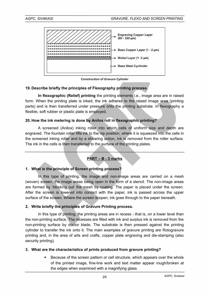
18. State briefly the construction of gravure cylinder.
Basically the gravure cylinder is made up of steel. Over the steel core cylinder, a
nickel layer coating of 1 to 3 µm is applied. Then the cylinder receives a base copper layer of
1-2 µm. Then the application of another layer i.e., engraved copper layer of 80 to 320 µm is
applied over the base copper layer.
23
AGPC, Sivakasi
AGPC, SIVAKASI GRAVURE, FLEXO AND SCREEN PRINTING
19. Describe briefly the principles of Flexography printing process.
In flexographic (Relief) printing the printing elements i.e., image area are in raisedform. When the printing plate is inked, the ink adheres to the raised image area (printingparts) and is then transferred under pressure onto the printing substrate. In flexography aflexible, soft rubber or plastic plate is employed.
20. How the ink metering is done by Anilox roll in flexographic printing?
A screened (Anilox) inking roller into which cells of uniform size and depth areengraved. The fountain roller lifts ink to the nip position, where it is squeezed into the cells inthe screened inking roller and by a shearing action, ink is removed from the roller surface.The ink in the cells is then transferred to the surface of the printing plates.
PART – B - 3 marks
1. What is the principle of Screen printing process?
In this type of printing, the image and non-image areas are carried on a mesh(woven) screen, the image areas being open in the form of a stencil. The non-image areasare formed by ‘blocking out’ the mesh by coating. The paper is placed under the screen.After the screen is lowered into contact with the paper, ink is passed across the uppersurface of the screen. Where the screen is open, ink goes through to the paper beneath.
2. Write briefly the principles of Gravure Printing process.
In this type of printing, the printing areas are in recess - that is, on a lower level thanthe non-printing surface. The recesses are filled with ink and surplus ink is removed from thenon-printing surface by doctor blade. The substrate is then pressed against the printingcylinder to transfer the ink onto it. The main examples of gravure printing are Rotogravureprinting and, in the area of arts and crafts, copper plate engraving and die-stamping (alsosecurity printing).
3. What are the characteristics of prints produced from gravure printing?
Because of the screen pattern or cell structure, which appears over the whole
of the printed image, fine-line work and text matter appear rough/broken atthe edges when examined with a magnifying glass.
24
AGPC, Sivakasi
AGPC, SIVAKASI GRAVURE, FLEXO AND SCREEN PRINTING
Wide range of tonal values is possible, giving an effect of continuous tone-like
quality (especially in four-colour process work). Under a magnifying glass the ‘screen pattern’ in conventional gravure is seen
to be of a regular square formation (showing uniform cells). The final printed images are of excellent visual quality. Due to its intaglio
character, the closeness of the printing areas and different thickness of ink,gravure print displays the pleasing effect of a continuous tone image.
4. Write briefly about the image carriers used for gravure printing.
Gravure image carrier
Copper plates
Gravure plates are made from rolled copper. The ends of the plate must be carefully
bent to fit in to the clamps on the cylinder. The plate covers only parts of the cylinder
circumference since the plate cylinder must house the clamping system. This uncovered
section must be filled in with a “gap cover” or “segment” to provide a bearing surface for the
doctor blade. These type of presses (using a gravure plate) are fast becoming absolete.
Copper cylinder
Cylinders can be made of iron, steel, copper or aluminium. Solid (Integral) cylinders
are invariably used on web-fed presses. The thickness of the copper deposit varies
depending upon the circumference, length and construction of the cylinder. The copper
deposit ranges from 0.015 to 0.050 inch thick, and copper is deposted slightly more than the
required thickness. Afterwards the cylinder is taken out and brought to the required diameter
by turning it on a lathe; then it is polished to a high luster. The accuracy of the cylinder is
maintained within a tolerance of + or – 0.0005 inches. (In the cylinder, image areas are on a
sunken (lower) level than the non image areas).
5. Write notes on doctor blade.
The printing cylinder is flooded with ink and before impression is made on the paper,
the excess ink from the cells and on the non-printing surface of the cylinder is removed by
the scraping action of a flexible sheet blade, known as “Doctor Blade”. As the cylinder turns,
and just before the paper makes contact with it, this doctor blade, made of fine Swedish
steel (.008 inch thick) wipes off all the excess ink. The doctor blade, precision ground and
hand coned (after use), is held against the cylinder under pressure, and scrapes the cylinder
surface absolutely dry.
6. Write notes on dryers in flexographic presses.
The Drying section require an after-drier to remove the remaining solvent from all the
colours before the web can be wound in to a roll. The drying section may also require
between-color driers between printing units on multi color presses to permit the necessary
printing of color on color. The removal of solvents can be accomplished in several ways, hot
air current being the most common. However revolutionary method of drying are being
investigated.
25
AGPC, Sivakasi
AGPC, SIVAKASI GRAVURE, FLEXO AND SCREEN PRINTING
An exhaust system conjunction with the after dryer prevents a build of solvent laden
air that might become an explosive hazard: In between color hot air dryers it is essential that
the exhaust exist the warm air supply, otherwise the location of these dryers in the very
minimal space between color units would result in warm air being blown on to the inking
rollers and plate cylinders. Premature ink drying would seriously interfere with the inking of
the plates and printing of their image on to the web.
7. Write notes on screen fabrics used for screen printing.
Screen Fabric :
The screen fabric is a woven material. It is a tightly stretched across the frame. This
Screen fabric serves as a carrier for stencil. The selection of fabric for particular work plays a
major role. Following are the types of fabrics.
a) Silk:
Silk is a natural fiber produced by the silk worm. Hand cut and indirect stencils
adhere well to silk fabrics. However this silk is not dimensionally stable. Size variation can
occur due to change in temperature and humidity. Therefore silk is unsuitable for jobs
requiring critical registration.
(b) Polyesters:
Polyesters such as darcon, Terital and polylast are man-made synthetic materials
containing cellulose, resins and hydrocarbons. Polyesters fabrics are woven very uniformly
and possess good dimension stability. They are extremely strong and used for long runs. A
major disadvantage is that indirect photographic stencil will not adhere so good as like in
silk.
(c) Nylon:
Nylon is also a man-made synthetic material having uniformly woven fabrics. This
fabric is strong and durable and can be used for long run jobs. Unlike polyesters, nylon
fabrics lack dimensional stability. Nylon fabrics will go on stretched and react to temperature
& humidity changes. So before mounting a nylon fabric on frames, it should be wet firstly and
stretched very taut, to maintain the good registration.
d) Metal fabrics:
These types of fabrics are used for only special application. Unlike the synthetic
fabric, it does not absorb moisture and is therefore unaffected by changes in humidity. Also it
is unaffected by temperature. As it has very good dimensional stability it is used for very
precision printing like printed circuit board or very specialized application. Usually “Stainless
Steel wire” is used as a metal fabric.
8. State the functions of squeegees in screen printing.
The squeegee performs a very important function in screen printing. It is used to
force the ink through the screen mesh and stencil on to the printing stock below. Squeegee
blades are made from high quality natural rubbers and synthetic material. Polyurethane
26
AGPC, Sivakasi
AGPC, SIVAKASI GRAVURE, FLEXO AND SCREEN PRINTING
squeegee blades are now- a-days used widely due to their resistance property to abrasion
so there is no need for sharpening or reshaping.
Squeegeees are normally supplied in three grades : Hard, Medium, Soft. The hard
and medium grades are used for printing thin film inks, the soft grade is used for printing on
to non-absorbent materials such as metal & glass. During the printing action the squeegee is
moved across the screen and force the ink to pass through the mesh opening.
9. What are the applications of screen printing process?
Sheet-fed Screen printing
As the process is best known for its ability to print a thicker ink film than any other
printing process this makes it ideal for printing light coloured inks on dark coloured materials,
also onto awkward, rough surfaces, uneven and moulded shape surfaces. Examples include
posters, showcards, printed circuits, T-shirts, printing on cloth, vinyl, metal, glass and plastic,
etc.
Rotary/web-fed Screen Printing
Specialist area of the process used for self-adhesive labels, scratch-off lottery tickets,
packaging, transfer printing, fabric printing, security printing, direct mail and high quality
greetings cards with die-cutting and additional finishing requirements.
PART - C: 10 Marks Questions
1. Describe the principles of Gravure printing process with suitable diagrams.
2. Explain the principles of flexographic printing process with necessary sketches.
3. Explain the principles of screen printing process with suitable diagrams.
4. Describe the main sections of Gravure printing machine with sketches.
5. Explain the main sections of Flexographic printing machine with diagrams.
6. Describe the main sections of screen printing machine with necessary sketches.
GLOSSARY
Aniline
The former term for flexography; the name was derived from aniline dyes obtainedfrom coal tar (an obsolete technology).
Dancer Roll
A web-tensioning device in the form of a roller that uses weights or springs whichmonitors web tension by controlling the unwind brake or rewind tension.
Driving Side
That side of a flexographic press on which the main gear train(s) are located; alsogear side; opposite of operating side.
27
AGPC, Sivakasi
AGPC, SIVAKASI GRAVURE, FLEXO AND SCREEN PRINTING
Dryer
That auxiliary unit of a flexographic printing press through which the printed webtravels and is dried prior to rewinding. Drying units are placed as required between colorstations.
Gravure
A printing process in which the image area is etched below the surface of the printingplate. The ink is carried below the printing surface in small wells or lines etched or scribedinto a metal plate. The surface of the plate is wiped clean so nonimage areas carry no inkand the image is transferred directly to the paper by means of pressure.
Infeed
A mechanism designed to control the forward travel of the web into the press.
In-Line Press
1. A press coupled to another operation such as a bag making, sheeting, diecutting,creasing, etc;
2. A multicolor press in which the color stations are mounted horizontally in a line.
Intaglio
An engraved or etched design which is below the surface as cells in an anilox roll or
gravure cylinder.
Letterpress
A method of printing that uses hard-relief plates as an image carrier. The image area
of the plate, raised above the nonprinting area, receives the ink and is then transferred
directly to the substrate.
28
AGPC, Sivakasi
AGPC, SIVAKASI GRAVURE, FLEXO AND SCREEN PRINTING
UNIT - II – IMAGE CARRIER PREPARATION
2.1. FLEXOGRAPHIC IMAGE CARRIER PREPARATION
Flexographic Plate
The first plates developed for flexographic printing were made of natural or, more
commonly, synthetic rubber, and were manufactured much like letterpress plates. Although
photopolymer plates are now widely used in flexographic platemaking, rubber still has its
adherents, primarly because of its economy, its simplicity, and its compatibility with ink
solvents that cannot be used with photopolymer plates.
Structure of Flexographic Plate
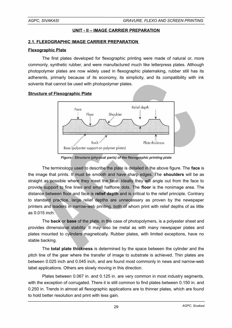
Figure - Structure (physical parts) of the flexographic printing plate
The terminology used to describe the plate is detailed in the above figure. The face is
the image that prints. It must be smooth and have sharp edges. The shoulders will be as
straight as possible where they meet the face. Ideally they will angle out from the face to
provide support to fine lines and small halftone dots. The floor is the nonimage area. The
distance between floor and face is relief depth and is critical to the relief principle. Contrary
to standard practice, large relief depths are unnecessary as proven by the newspaper
printers and leaders in narrow-web printing, both of whom print with relief depths of as little
as 0.015 inch.
The back or base of the plate, in the case of photopolymers, is a polyester sheet and
provides dimensional stability. It may also be metal as with many newspaper plates and
plates mounted to cylinders magnetically. Rubber plates, with limited exceptions, have no
stable backing.
The total plate thickness is determined by the space between the cylinder and the
pitch line of the gear where the transfer of image to substrate is achieved. Thin plates are
between 0.025 inch and 0.045 inch, and are found most commonly in news and narrow-web
label applications. Others are slowly moving in this direction.
Plates between 0.067 in. and 0.125 in. are very common in most industry segments,
with the exception of corrugated. There it is still common to find plates between 0.150 in. and
0.250 in. Trends in almost all flexographic applications are to thinner plates, which are found
to hold better resolution and print with less gain.
29
AGPC, Sivakasi
AGPC, SIVAKASI GRAVURE, FLEXO AND SCREEN PRINTING
There are several kinds of image carrier used in flexography
1. The traditional rubber plate
2. Photopolymer plates
3. Laser-engraved rubber plates or rubber rollers.
Flexographic plate composition must match to some extent the type of ink to be used
and to the substrate to be printed. Both rubber and photopolymer plates are used.
2.1.1. RUBBER FLEXOGRAPHIC PLATES PREPARATION (IN BRIEF)
Natural and synthetic rubber plates were the first type of flexo plates developed, and
they are still used for some applications. The process of producing a rubber plate is not far
different from the process used to produce photoengravings used in the hot type letterpress
process (figure).
i. Preparation of Original Plate
A sheet of metal alloy coated with a light-sensitive emulsion is first placed in a
specially designed vacuum frame. The emulsion is not only light-sensitive, it is also an acid
resist.
A negative is placed over the emulsion and light is passed through the negative. The
acid resist hardens where light strikes the emulsion (image areas).
During processing, the unhardened resist in the non-image areas is washed away,
leaving hardened resist only on the image areas. The metal alloy is then etched, which
lowers the non-image areas and leaves the image areas raised. The remaining resist is
washed off.
ii. Preparation of Mold or Matrix
The completed engraving is then moved to a molding press where a matrix (mold) of
the engraving is made by pressing matrix material against the engraving with controlled heat
and pressure. The matrix material sinks into the metal engraving to form the mold.
iii. Preparation of Rubber Plate
The rubber plate is made from the matrix by pressing a rubber sheet into the matrix,
again under controlled heat and pressure.
Preformed sheets for rubber plates are available in a variety of thick nesses. The
thickness depends on the job to be printed and the press to be used.
The major disadvantage of rubber plates is that they are more costly to make than
photopolymer plates. Also, because they are made from an engraving, any plate problems
identified during proofing must be corrected by remaking the engraving, which further
increases the expense of the process.
2.1.2. PHOTOPOLYMER FLEXOGRAPHIC PLATES
30
AGPC, Sivakasi
AGPC, SIVAKASI GRAVURE, FLEXO AND SCREEN PRINTING
Photopolymer plates are made from light-sensitive polymers (plastics). When they
are exposed to ultra violet light, they undergo polymerization, or the chemical conversion of
many small molecules into long-chain molecules. The result is that they will be harder and
more insoluble in exposed areas and softer in unexposed areas. Photopolymer plates
eliminate many of the disadvantages of rubber plates. There are two basic types of
photopolymer plates used in flexographic platemaking - Sheet photopolymer plates & Liquid
photopolymer plates.
2.1.2.a. SHEET PHOTOPOLYMER FLEXOGRAPHIC PLATES PREPARATOPN (IN BRIEF)
Sheet photopolymer plates are supplied in a variety of thicknesses for specificapplications. These plates are cut to the required size and placed in an ultraviolet lightexposure unit (figure). One side of the plate is completely exposed to ultraviolet light toharden or cure the base of the plate.
The plate is then turned over, a negative of the job is mounted over the uncured side,and the plate is again exposed to ultraviolet light. This hardens the plate in the image areas.
The plate is then processed to remove the unhardened photopolymer from thenonimage areas, which lowers the plate surface in these nonimage areas.
After processing, the plate is dried and given a postexposure dose of ultraviolet lightto cure the whole plate.
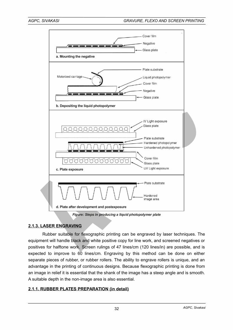
2.1.2.b. LIQUID PHOTOPOLYMER FLEXOGRAPHIC PLATES (IN BRIEF)
Liquid photopolymer plates are made in a special ultraviolet light exposure unit. Inthis process, a clear plastic protective cover film is mounted over a negative transparencywhich is placed emulsion side up on the exposure unit (figure a).
A layer of liquid photopolymer is then deposited by a motorized carriage over thetransparency and cover film. The carriage deposits the liquid evenly over the cover film andcontrols the thickness of the deposit. While the carriage deposits the liquid, it also places asubstrate sheet over the liquid (figure b).
The substrate sheet is specially coated on one side to bond with the liquidphotopolymer and to serve as the back of the plate after exposure.
Exposure is made first on the substrate side of plate. This exposure hardens a thinbase layer of the liquid photopolymer and causes it to adhere to the plate substrate. Asecond exposure through the negative forms the image on the plate (figure c). As with sheetmaterials, the image areas are hardened by this exposure. The non-image areas, however,remain liquid.
Processing removes unwanted liquid in the non-image areas to leave raised imageareas. A post-exposure is then made to cure the whole plate (figure d).
31
AGPC, Sivakasi
AGPC, SIVAKASI GRAVURE, FLEXO AND SCREEN PRINTING
a. Mounting the negative
b. Depositing the liquid photopolymer
c. Plate exposure
d. Plate after development and postexposure
Figure: Steps in producing a liquid photopolymer plate
2.1.3. LASER ENGRAVING
Rubber suitable for flexographic printing can be engraved by laser techniques. The
equipment will handle black and white positive copy for line work, and screened negatives or
positives for halftone work. Screen rulings of 47 lines/cm (120 lines/in) are possible, and is
expected to improve to 60 lines/cm. Engraving by this method can be done on either
separate pieces of rubber, or rubber rollers. The ability to engrave rollers is unique, and an
advantage in the printing of continuous designs. Because flexographic printing is done from
an image in relief it is essential that the shank of the image has a steep angle and is smooth.
A suitable depth in the non-image area is also essential.
2.1.1. RUBBER PLATES PREPARATION (in detail)
32
AGPC, Sivakasi
AGPC, SIVAKASI GRAVURE, FLEXO AND SCREEN PRINTING
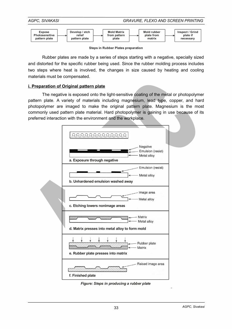
ExposePhotosensitivepattern plate
Develop / etchrelief
pattern plate
Mold Matrixfrom pattern
plate
Mold rubberplate from
matrix
Inspect / Grindplate if
necessary
Steps in Rubber Plates preparation
Rubber plates are made by a series of steps starting with a negative, specially sized
and distorted for the specific rubber being used. Since the rubber molding process includes
two steps where heat is involved, the changes in size caused by heating and cooling
materials must be compensated.
i. Preparation of Original pattern plate
The negative is exposed onto the light-sensitive coating of the metal or photopolymerpattern plate. A variety of materials including magnesium, lead type, copper, and hardphotopolymer are imaged to make the original pattern plate. Magnesium is the mostcommonly used pattern plate material. Hard photopolymer is gaining in use because of itspreferred interaction with the environment and the workplace.
a. Exposure through negative
b. Unhardened emulsion washed away
c. Etching lowers nonimage areas
d. Matrix presses into metal alloy to form mold
e. Rubber plate presses into matrix
f. Finished plate
Figure: Steps in producing a rubber plate
33
AGPC, Sivakasi
AGPC, SIVAKASI GRAVURE, FLEXO AND SCREEN PRINTING
The pattern plate is processed into a hard, letterpress-type relief plate. This becomesthe “original” relief plate that will be duplicated in rubber for use in flexographic printing.Metal pattern plates are developed after exposure to remove the acid-resistant coating. Theplate is etched with acid to the desired depth. This determines the relief depth of the finalrubber plate. Then the plate is inspected and flaws are removed to prepare it for making thematrix, a mold.
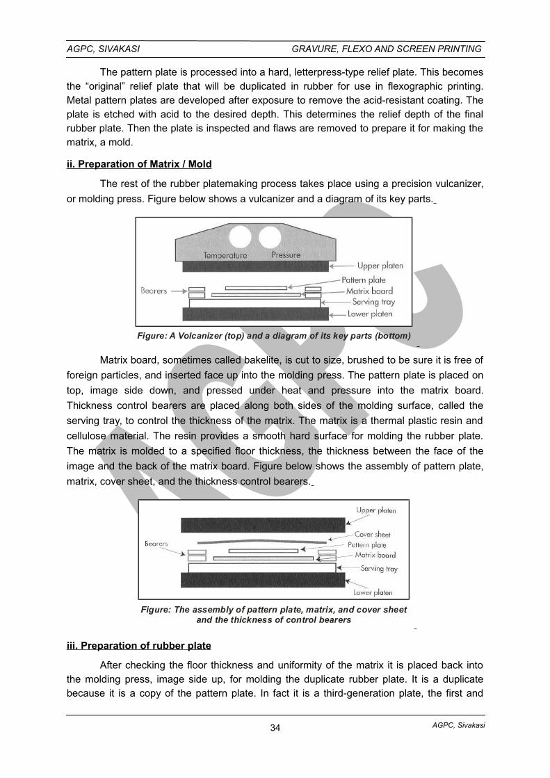
ii. Preparation of Matrix / Mold
The rest of the rubber platemaking process takes place using a precision vulcanizer,
or molding press. Figure below shows a vulcanizer and a diagram of its key parts.
Figure: A Volcanizer (top) and a diagram of its key parts (bottom)
Matrix board, sometimes called bakelite, is cut to size, brushed to be sure it is free of
foreign particles, and inserted face up into the molding press. The pattern plate is placed on
top, image side down, and pressed under heat and pressure into the matrix board.
Thickness control bearers are placed along both sides of the molding surface, called the
serving tray, to control the thickness of the matrix. The matrix is a thermal plastic resin and
cellulose material. The resin provides a smooth hard surface for molding the rubber plate.
The matrix is molded to a specified floor thickness, the thickness between the face of the
image and the back of the matrix board. Figure below shows the assembly of pattern plate,
matrix, cover sheet, and the thickness control bearers.
Figure: The assembly of pattern plate, matrix, and cover sheetand the thickness of control bearers
iii. Preparation of rubber plate
After checking the floor thickness and uniformity of the matrix it is placed back intothe molding press, image side up, for molding the duplicate rubber plate. It is a duplicatebecause it is a copy of the pattern plate. In fact it is a third-generation plate, the first and
34
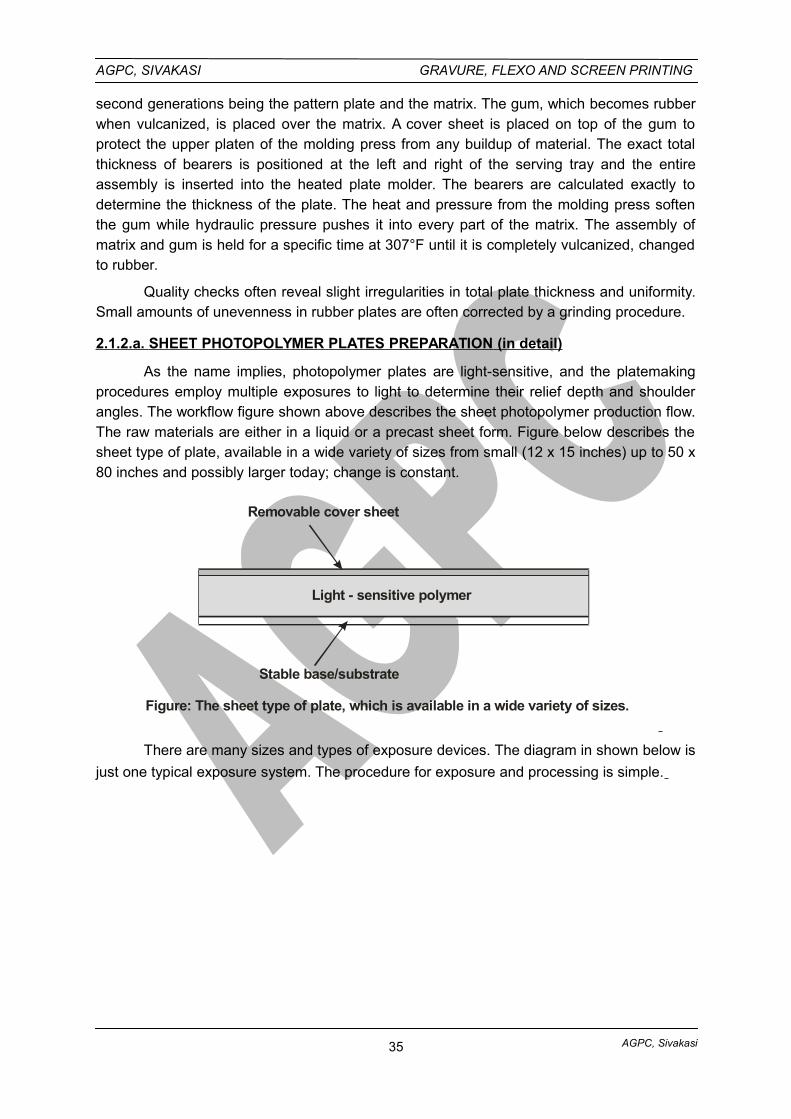
AGPC, Sivakasi
AGPC, SIVAKASI GRAVURE, FLEXO AND SCREEN PRINTING
second generations being the pattern plate and the matrix. The gum, which becomes rubberwhen vulcanized, is placed over the matrix. A cover sheet is placed on top of the gum toprotect the upper platen of the molding press from any buildup of material. The exact totalthickness of bearers is positioned at the left and right of the serving tray and the entireassembly is inserted into the heated plate molder. The bearers are calculated exactly todetermine the thickness of the plate. The heat and pressure from the molding press softenthe gum while hydraulic pressure pushes it into every part of the matrix. The assembly ofmatrix and gum is held for a specific time at 307°F until it is completely vulcanized, changedto rubber.
Quality checks often reveal slight irregularities in total plate thickness and uniformity.Small amounts of unevenness in rubber plates are often corrected by a grinding procedure.
2.1.2.a. SHEET PHOTOPOLYMER PLATES PREPARATION (in detail)
As the name implies, photopolymer plates are light-sensitive, and the platemakingprocedures employ multiple exposures to light to determine their relief depth and shoulderangles. The workflow figure shown above describes the sheet photopolymer production flow.The raw materials are either in a liquid or a precast sheet form. Figure below describes thesheet type of plate, available in a wide variety of sizes from small (12 x 15 inches) up to 50 x80 inches and possibly larger today; change is constant.
Light - sensitive polymer
Removable cover sheet
Stable base/substrate
Figure: The sheet type of plate, which is available in a wide variety of sizes.
There are many sizes and types of exposure devices. The diagram in shown below is
just one typical exposure system. The procedure for exposure and processing is simple.
35
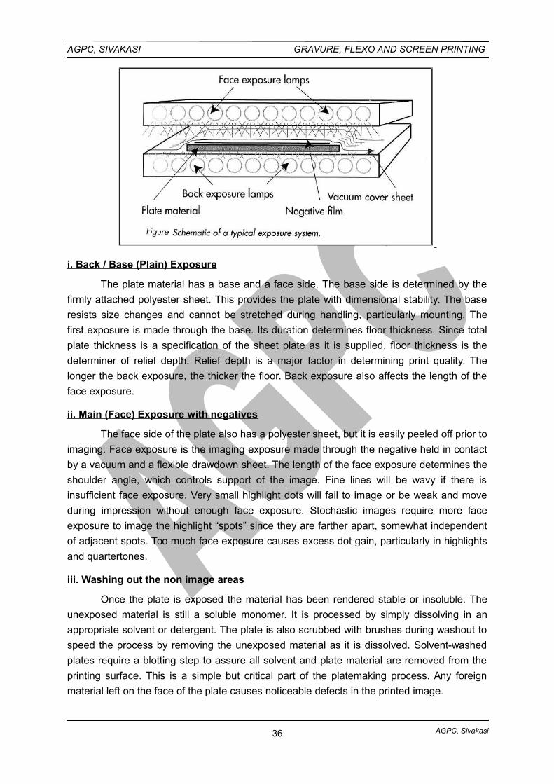
AGPC, Sivakasi
AGPC, SIVAKASI GRAVURE, FLEXO AND SCREEN PRINTING
i. Back / Base (Plain) Exposure
The plate material has a base and a face side. The base side is determined by the
firmly attached polyester sheet. This provides the plate with dimensional stability. The base
resists size changes and cannot be stretched during handling, particularly mounting. The
first exposure is made through the base. Its duration determines floor thickness. Since total
plate thickness is a specification of the sheet plate as it is supplied, floor thickness is the
determiner of relief depth. Relief depth is a major factor in determining print quality. The
longer the back exposure, the thicker the floor. Back exposure also affects the length of the
face exposure.
ii. Main (Face) Exposure with negatives
The face side of the plate also has a polyester sheet, but it is easily peeled off prior to
imaging. Face exposure is the imaging exposure made through the negative held in contact
by a vacuum and a flexible drawdown sheet. The length of the face exposure determines the
shoulder angle, which controls support of the image. Fine lines will be wavy if there is
insufficient face exposure. Very small highlight dots will fail to image or be weak and move
during impression without enough face exposure. Stochastic images require more face
exposure to image the highlight “spots” since they are farther apart, somewhat independent
of adjacent spots. Too much face exposure causes excess dot gain, particularly in highlights
and quartertones.
iii. Washing out the non image areas
Once the plate is exposed the material has been rendered stable or insoluble. The
unexposed material is still a soluble monomer. It is processed by simply dissolving in an
appropriate solvent or detergent. The plate is also scrubbed with brushes during washout to
speed the process by removing the unexposed material as it is dissolved. Solvent-washed
plates require a blotting step to assure all solvent and plate material are removed from the
printing surface. This is a simple but critical part of the platemaking process. Any foreign
material left on the face of the plate causes noticeable defects in the printed image.
36
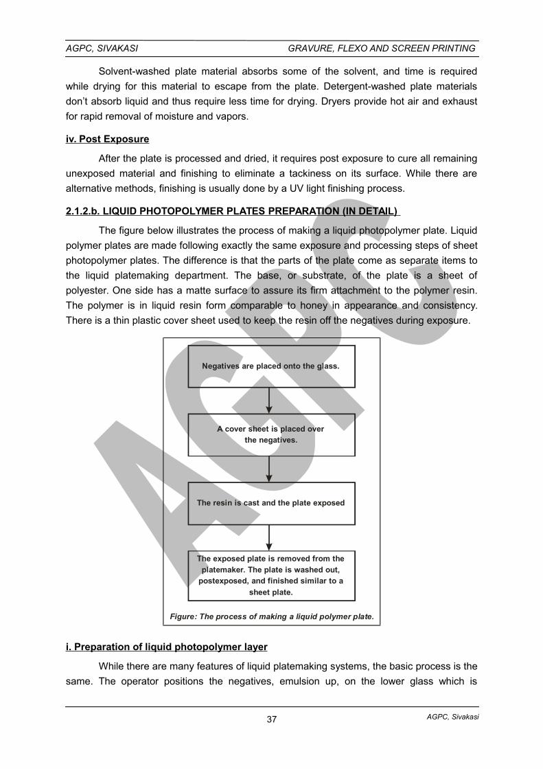
AGPC, Sivakasi
AGPC, SIVAKASI GRAVURE, FLEXO AND SCREEN PRINTING
Solvent-washed plate material absorbs some of the solvent, and time is required
while drying for this material to escape from the plate. Detergent-washed plate materials
don’t absorb liquid and thus require less time for drying. Dryers provide hot air and exhaust
for rapid removal of moisture and vapors.
iv. Post Exposure
After the plate is processed and dried, it requires post exposure to cure all remaining
unexposed material and finishing to eliminate a tackiness on its surface. While there are
alternative methods, finishing is usually done by a UV light finishing process.
2.1.2.b. LIQUID PHOTOPOLYMER PLATES PREPARATION (IN DETAIL)
The figure below illustrates the process of making a liquid photopolymer plate. Liquid
polymer plates are made following exactly the same exposure and processing steps of sheet
photopolymer plates. The difference is that the parts of the plate come as separate items to
the liquid platemaking department. The base, or substrate, of the plate is a sheet of
polyester. One side has a matte surface to assure its firm attachment to the polymer resin.
The polymer is in liquid resin form comparable to honey in appearance and consistency.
There is a thin plastic cover sheet used to keep the resin off the negatives during exposure.
Negatives are placed onto the glass.
A cover sheet is placed overthe negatives.
The resin is cast and the plate exposed
The exposed plate is removed from the
platemaker. The plate is washed out,postexposed, and finished similar to a
sheet plate.
Figure: The process of making a liquid polymer plate.
i. Preparation of liquid photopolymer layer
While there are many features of liquid platemaking systems, the basic process is the
same. The operator positions the negatives, emulsion up, on the lower glass which is
37
AGPC, Sivakasi
AGPC, SIVAKASI GRAVURE, FLEXO AND SCREEN PRINTING
cleaned before every plate is made. A very thin cover sheet is pulled over the negatives and
drawn down with vacuum.
The resin supply carriage moves across the negatives, pouring a metered quantity of
resin and simultaneously laying down the polyester base of the plate. As soon as the
carriage is clear of the plate area the top of the machine is closed and vacuum is applied
between the top and bottom glasses. This is done to assure the plate completely fills the
space between the two glasses. This space is the critical plate thickness and determines
plate uniformity required for quality flexographic printing.
ii. Exposure
The exposures are made. First the back exposure lamp is switched on. As with a
sheet system, this is timed to establish the floor thickness (and relief depth) while also
increasing the sensitivity of the resin to the face exposure. While the back exposure is being
made the face exposure is started from the bottom lamps. This exposure is made through
the negatives and determines the imaging and the shoulder support of the plate.
iii. Washing out
When the exposures are complete the unit is opened and the plate is removed. The
cover sheet is discarded and unexposed resin reclaimed. The plate is placed into the
processor washout unit; the processor washes out all the unexposed resin using a heated
detergent and water solution.
iv. Post Exposure
Once washed out, the plate is rinsed and moved to the finishing unit where it is post
exposed and finished simultaneously, in a special solution to remove the tackiness and to
leave the plate ready to be used once it has been dried. Drying is done only to remove water
from the surface since there is no absorption into the plate.
v. Finishing
Liquid platemaking departments almost always reclaim a significant amount of the
unexposed resin before the plate is washed out. This is done by placing it on a vertical
surface where, after removal of the cover sheet, a high-velocity air knife is passed down over
the plate causing the unexposed resin to roll off into a catch basin. This resin is used again
in the platemaking process, saving both material cost and pollution of the washout and
subsequent wastewater.
DIGITAL FLEXOGRAPHIC PLATES
Currently there are several varieties of direct-to-plate, or digitally imaged flexographic
plates. As with all printing processes, the motivation is to eliminate film imaging costs and
improve throughput. Of course, improvements in quality are also expected.
2.1.3. LASER ENGRAVING ON RUBBER ROLLERS
38
AGPC, Sivakasi
AGPC, SIVAKASI GRAVURE, FLEXO AND SCREEN PRINTING
The first direct-to-plate process was laser engraving rubber. In the process gum is
vulcanized and precisely ground to final plate thickness. It is then mounted to a drum and
rotated in front of a CO2 laser. The nonimage area is burned away leaving the image in relief
and the plate ready for mounting (see Figure 8-11). Laser-engraved rubber plates have
precisely controlled shoulder angle, and resolution as high as 120-line halftone screens can
be produced. One of the most appealing applications of this technology is the production of
continuous-pattern images. Conventional plates always leave a gap of line where the two
ends of the plate come together on the cylinder. Continuous patterns are laser-engraved
onto rubber-covered rollers. Rubber is vulcanized to roller bases and ground to the exact
repeat length. This roller is then laser-imaged. Gift wrap and wall covering often require
uninterrupted patterns, and laser imaging is a popular solution. This process also eliminates
any plate mounting and the cost of potential register flaws that go with mounting.
2.2. GRAVURE IMAGE CARRIER PREPARATION
HAND ENGRAVING AND PRINTING:
There are several methods of hand engraving and etching. These terms are usedinterchangeably, but actually should not be. To engrave is to cut an object with a tool and toetch is to remove by chemical-acid means.
Both engravings and etchings are true intaglio methods of reproducing images. Linesare cut or etched below the non image surface of the image carrier. The image carrier madeof copper, steel, or plastic, is then inked over the entire surface. The ink is wiped from thenon-image high portion, leaving the lines filled with ink. The image carrier is then pressedagainst a paper receptor to transfer the image.
GRAVURE IMAGE CARRIERS:
The three main types of gravure image carriers are 1) flat plate 2) wraparoundplate, and 3) cylinder.
Flat plates are used on special sheet-fed presses that produce stock certificates andother highgrade limited-copy materials.
Wrap-around plates are used to print art reproductions, books, mail order booklets,calendars, and packaging materials. The wrap-around plate is thin and flexible and attachesto a cylinder similar to one on an offset-lithography press. They can be used economicallyonly on short runs (30,00 copies or less). They cannot produce a continuous design orpattern because of the area needed to clamp the plate to the cylinder.
Cylinder image carriers are the most common within the industry; Preparation of agravure cylinder is a most critical process and each step in its production must be done withexacting care if quality results are expected.
GRAVURE CYLINDER MANUFACTURE
With the exception of sheet-fed gravure printing, which is now found only rarely, web-fed gravure printing requires a gapless gravure cylinder,onto which the image is applieddirectly,by means of etching or engraving. For this, the cylinder must be prepared in a costlymechanical and galvanic process.
39
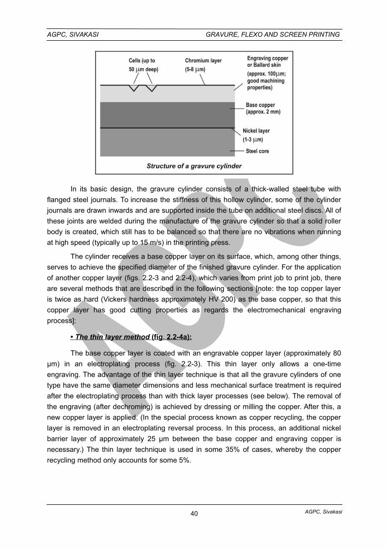
AGPC, Sivakasi
AGPC, SIVAKASI GRAVURE, FLEXO AND SCREEN PRINTING
In its basic design, the gravure cylinder consists of a thick-walled steel tube with
flanged steel journals. To increase the stiffness of this hollow cylinder, some of the cylinder
journals are drawn inwards and are supported inside the tube on additional steel discs. All of
these joints are welded during the manufacture of the gravure cylinder so that a solid roller
body is created, which still has to be balanced so that there are no vibrations when running
at high speed (typically up to 15 m/s) in the printing press.
The cylinder receives a base copper layer on its surface, which, among other things,
serves to achieve the specified diameter of the finished gravure cylinder. For the application
of another copper layer (figs. 2.2-3 and 2.2-4), which varies from print job to print job, there
are several methods that are described in the following sections [note: the top copper layer
is twice as hard (Vickers hardness approximately HV 200) as the base copper, so that this
copper layer has good cutting properties as regards the electromechanical engraving
process]:
• The thin layer method (fig. 2.2-4a):
The base copper layer is coated with an engravable copper layer (approximately 80
µm) in an electroplating process (fig. 2.2-3). This thin layer only allows a one-time
engraving. The advantage of the thin layer technique is that all the gravure cylinders of one
type have the same diameter dimensions and less mechanical surface treatment is required
after the electroplating process than with thick layer processes (see below). The removal of
the engraving (after dechroming) is achieved by dressing or milling the copper. After this, a
new copper layer is applied. (In the special process known as copper recycling, the copper
layer is removed in an electroplating reversal process. In this process, an additional nickel
barrier layer of approximately 25 µm between the base copper and engraving copper is
necessary.) The thin layer technique is used in some 35% of cases, whereby the copper
recycling method only accounts for some 5%.
40
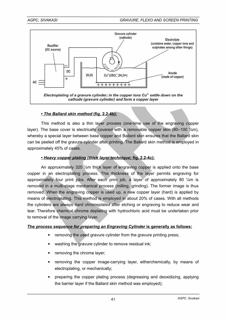
AGPC, Sivakasi
AGPC, SIVAKASI GRAVURE, FLEXO AND SCREEN PRINTING
• The Ballard skin method (fig. 2.2-4b):
This method is also a thin layer process (one-time use of the engraving copper
layer). The base cover is electrically covered with a removable copper skin (80–100 ¼m),
whereby a special layer between base copper and Ballard skin ensures that the Ballard skin
can be peeled off the gravure cylinder after printing. The Ballard skin method is employed in
approximately 45% of cases.
• Heavy copper plating (thick layer technique ; fig. 2.2-4c):
An approximately 320 ¼m thick layer of engraving copper is applied onto the base
copper in an electroplating process. This thickness of the layer permits engraving for
approximately four print jobs. After each print job, a layer of approximately 80 ¼m is
removed in a multi-stage mechanical process (milling, grinding). The former image is thus
removed. When the engraving copper is used up, a new copper layer (hard) is applied by
means of electroplating. This method is employed in about 20% of cases. With all methods
the cylinders are always hard chromeplated after etching or engraving to reduce wear and
tear. Therefore chemical chrome deplating with hydrochloric acid must be undertaken prior
to removal of the image carrying layer.
The process sequence for preparing an Engraving Cylinder is generally as follows:
removing the used gravure cylinder from the gravure printing press;
washing the gravure cylinder to remove residual ink;
removing the chrome layer;
removing the copper image-carrying layer, eitherchemically, by means of
electroplating, or mechanically;
preparing the copper plating process (degreasing and deoxidizing, applying
the barrier layer if the Ballard skin method was employed);
41
AGPC, Sivakasi
AGPC, SIVAKASI GRAVURE, FLEXO AND SCREEN PRINTING
electroplating;
surface finishing with a high-speed rotary diamond milling head and/or with a
burnishing stone or a polishing band;
etching or engraving (producing the image on the gravure cylinder);
test printing (proof print);
correcting the cylinder, minus or plus (i.e., reducing or increasing the volume
of cells);
preparing the chrome-plating process (degreasing and deoxidizing,
preheating, and – if necessary – sometimes polishing);
chrome-plating;
surface-finishing with a fine burnishing stone or abrasive paper;
storing the finished cylinder or installing it directly in the gravure printing
press.
Today, all these operations are performed, more or less fully automated, in
production lines, whereby overhead traveling cranes and in some cases the transportation of
the gravure cylinder from station to station is carried out by automated guided vehicle (AGV)
systems.
GRAVURE CYLINDER IMAGING
In addition to an image-carrying function, the screen structure of the gravure cylinder
surface has the significant task of guiding and supporting the doctor blade. The blade
supports itself on the cell walls, which demarcate the cells. The continuous-tone-like
graduation in the image of conventional gravure (etching) is achieved through the various
depths of the cells.
However, there is a mixed form, the variable area and depth gravure process, in
which the cell diameter and depth of the cells are altered for the continuous tone graduation
Variable area gravure printing without cell depth variation (corresponding to the dot
size variation in offset and letterpress printing) has gained little significance.
Electromechanical engraving with diamond stylus (variable area and depth gravure)
is the dominant process. Only seldom is etching still used as an imaging process in gravure
printshops. Despite this, and in the interests of thoroughness, a short description of this
process is given below.
GRAVURE ENGRAVING
Collective term for the various means of engraving or etching the image onto the
gravure cylinder. Gravure, unlike most other printing processes, prints from depressed,
inkfilled cells produced on the surface of a copper-plated cylinder. The ink in the cells is then
transferred to the desired substrate.
42
AGPC, Sivakasi
AGPC, SIVAKASI GRAVURE, FLEXO AND SCREEN PRINTING
The four basic means of engraving the image into a gravure cylinder are
i. the diffusion-etch process or carbon tissue or conventional method
ii. the directtransfer process or halftone gravure process
iii. electromechanical engraving, and
iv. the laser-cutting process.
I. CONVENTIONAL CYLINDER PREPARATIONS:
Conventional methods of cylinder preparation date back to the nineteenth century
when the first commercial application of the intaglio mechanical principles took place. This
early effort took into account the concept of a pattern of square dots, all the same size
laterally arranged. The etched cells in highlight areas are very shallow, with the depth
increasing in direct ratio to the incerase in tone. Tones are thus determined by the thickness
of the ink film in the cells, rather than by the size of the dots. Principles of this form the basis
for virtually all other gravure processes.
PREPARING OF GRAVURE CYLINDER BY CONVENTIONAL METHOD OR CARBONTISSUE METHOD
It is necessary to prepare film positives for gravure production.
Preparation of Originals
1. Prepare photographs, artwork, and type composition necessay for the images.
Film Processing
2. The type and artwork are photographed in a process camera to obtain the film
negative.
3. The continuous-tone film negatives (those that contain no dots) are prepared from
photographs that contain varying shades of gray.
4. The film negatives are then carefully retouched by the engraver to correct
imperfections.
5. The retouched negatives are set up in proper position and a one-piece film positive
combining all elements of the image, is made.
6. The engraver carefully inspects the film positive and retouches it to make final
corrections and adjustments.
7. Several film positives are stripped together for the image to cover the entire
cylinder.
8. Photographic proofs are made of the film positives and the engraver closely
inspects them for needed correction.
Readying (Preparation) of the Cylinder :
43

AGPC, Sivakasi
AGPC, SIVAKASI GRAVURE, FLEXO AND SCREEN PRINTING
During the time that the film positives are being prepared, the surface of the gravurecylinder is prepared to accept the iamge. The cylinder must be carefully prepared before theetched image is placed onto it.
9. The thin coating of copper, containing the image used on the previous printing job,is removed. This is done on a special gravure cutting lathe.
10. A new coating of copper must be placed on the cylinder surface. To do this thecylinder is placed into an electroplating tank coated with copper to approximately 0.005 inchover the specified finished diameter.
11. The cylinder is accurately centered in a high-precision lathe and is cut to a finefinish with a diamond tool to within 0.002 inch.
12. The cylinder is placed on a special grinder and super finished to the exactspecified diameter and smoothness. It is now ready to receive the image.
Exposing the Image :
The entire image is screened in the gravure process. This includes the type, artwork,and photographs. Special gravure screens containing 150 to 300 lines to the inch are used.A sheet of carbon tissue, coated with a layer of orange-colored light sensitive gelatin on apaper backing sheet, is placed in contact with a gravure screen. Both items are placed invaccum frame.
Exposure with Gravure Screen :
13. The carbon tissue is exposed to strong arc lamps through the screen. Thetransparent lines of the screen allow light to strike the carbon tissue, hardening it and makingit insoluble to the etching solution which wil later be placed upon it.
Exposure with film positive (image) :
14. The screen is removed from the carbon tissue and the film positive is placed overthe tissue. The tissue is again exposed to light source through the film positive. The gelatinsensitized coating of the carbon tissue hardens in proportion to the amount of light thatpasses through the positive. In highlight or lightest areas the gelatin is hardened to thegreatest amount; in shadow areas (darkest) it is hardened to the least.
Mounting the carbon tissue on cylinder
15. The exposed carbon tissue, containing the complete image, is transferred
carefully to the copper cylinder. It is important to place the tissue in exactly the correct
position on the cylinder.
The transfer machine places approximately 1,300 pounds of pressure per square
inch on the carbon tissue to make it adhere properly to the copper cylinder.
Peeling off paper back from carbon tissue
16. After the carbon tissue has been adhered to the cylinder, the paper backing is
removed and hot water is used to wash away unhardened gelatin remaining where the light
did not penetrate. Large nonimage areas of the cylinder are “staged out” (hand painted with
asphaltum) to resist the action of the etching solution. The cylinder is now ready for etching.
44
AGPC, Sivakasi
AGPC, SIVAKASI GRAVURE, FLEXO AND SCREEN PRINTING
Etching the Cylinder :
17. The cylinder is carefully removed from the transfer machine to the etching trough.
The etching solution (ferric chloride solution) can be either poured onto the rotating copper
cylinder or placed in an etching machine that allows the cylinder to rotate constantly in a
bath of acid. The etching solution penetrates the gelatin and attacks the copper.
The etching depth of the copper is determined by the thickness of gelatin in each
rectangular dot. Because the gelatin is thickest within the highlight area of the image, it takes
a longer period of time before the etch penetrates it. The depth of the etching within that
area is therefore vey slight. Within the shadow area of the image there is only a small
amount of gelatin to protect the cylinder, and the etching solution quickly attacks the copper
and etches to greater depth. The shadow cells are etched to approximately 38 microns in
depth; highlight cells to 3 or 4 microns. Cells of depth between these extremes represent the
middle tones. (25 microns = 0.001 inch.)
18. The cylinder is carefully inspected microscopically after it has been etched for a
period of time. If any flaws appear it is possible to re-etch to corect the defect.
PROOFING AND FINISHING THE CYLINDER:
19. The cylinder is proofed on a special gravure press after inspection. The proof
results are compared with the original copy. If flaws are found in the cylinder, it is possible for
the finisher to hand-correct them.
20. A thin chrome plating is done over the copper cylinder surface after it is
considered to be perfect. The chrome is much harder than the copper and offer better
resistance to wear for many more copies. The cylinder is now completely prepared and is
ready to be placed on the printing press.
OTHER METHODS OF CYLINDER PREPARATIONS:
Several variations in methods of preparing the gravure cylinder are now practiced.
Each method of special technique has special advantages, and also disadvantages. The
major difference between these processes and the conventional gravure process is that in
the former the square dots vary in size as well as depth. This allows a wider range of tonal
values.
III. ELECTRONIC / ELECTROMECHANICAL ENGRAVING OF GRAVURE CYLINDERS:
Present procedures for producing gravure cylinders are time consuming and demand
several skilled personnel. Electronic engraving machines reduce the amount of production
time and labour.
Electromechanical engraving appeared as a commercial process in the late 1960s
and has almost completely replaced earlier chemical processes. In its simplest form, the
engraving machine has three basic parts:
i. a scanning head and cylindrical drum for mounting copy, or a digital input
device;
45
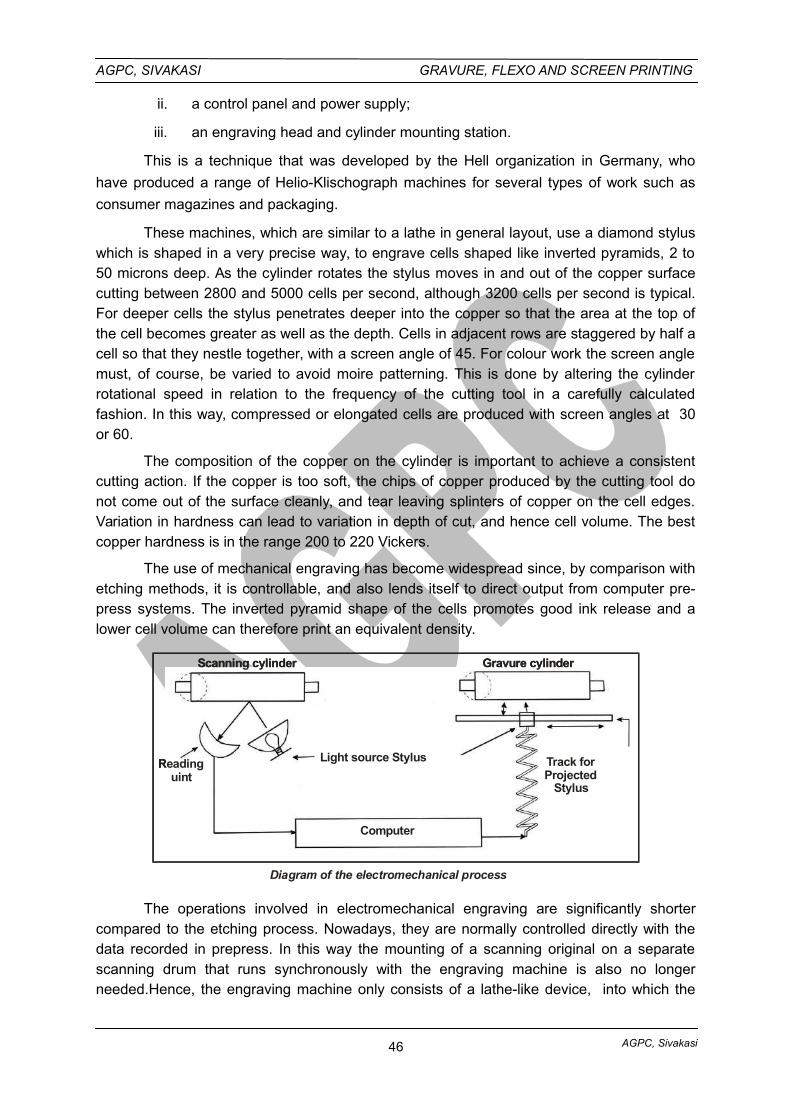
AGPC, Sivakasi
AGPC, SIVAKASI GRAVURE, FLEXO AND SCREEN PRINTING
ii. a control panel and power supply;
iii. an engraving head and cylinder mounting station.
This is a technique that was developed by the Hell organization in Germany, who
have produced a range of Helio-Klischograph machines for several types of work such as
consumer magazines and packaging.
These machines, which are similar to a lathe in general layout, use a diamond styluswhich is shaped in a very precise way, to engrave cells shaped like inverted pyramids, 2 to50 microns deep. As the cylinder rotates the stylus moves in and out of the copper surfacecutting between 2800 and 5000 cells per second, although 3200 cells per second is typical.For deeper cells the stylus penetrates deeper into the copper so that the area at the top ofthe cell becomes greater as well as the depth. Cells in adjacent rows are staggered by half acell so that they nestle together, with a screen angle of 45. For colour work the screen anglemust, of course, be varied to avoid moire patterning. This is done by altering the cylinderrotational speed in relation to the frequency of the cutting tool in a carefully calculatedfashion. In this way, compressed or elongated cells are produced with screen angles at 30or 60.
The composition of the copper on the cylinder is important to achieve a consistentcutting action. If the copper is too soft, the chips of copper produced by the cutting tool donot come out of the surface cleanly, and tear leaving splinters of copper on the cell edges.Variation in hardness can lead to variation in depth of cut, and hence cell volume. The bestcopper hardness is in the range 200 to 220 Vickers.
The use of mechanical engraving has become widespread since, by comparison withetching methods, it is controllable, and also lends itself to direct output from computer pre-press systems. The inverted pyramid shape of the cells promotes good ink release and alower cell volume can therefore print an equivalent density.
Scanning cylinder Gravure cylinder
Readinguint
Light source Stylus
Computer
Track forProjected
Stylus
Scanning cylinder Gravure cylinder
Readinguint
Light source Stylus
Computer
Track forProjected
Stylus
Diagram of the electromechanical process
The operations involved in electromechanical engraving are significantly shortercompared to the etching process. Nowadays, they are normally controlled directly with thedata recorded in prepress. In this way the mounting of a scanning original on a separatescanning drum that runs synchronously with the engraving machine is also no longerneeded.Hence, the engraving machine only consists of a lathe-like device, into which the
46
AGPC, Sivakasi
AGPC, SIVAKASI GRAVURE, FLEXO AND SCREEN PRINTING
prepared gravure cylinder is mounted. The engraving procedure is similar to a rotatingcutting process, but the cut is intermittent (stylus frequency).
The gravure cylinder rotates during engraving at a constant surface speed(depending on the screen at approximately 1 m/s).At the same time the diamond stylus ofthe engraving head moves at a high frequency (4–8 kHz). The diamond penetrates thecopper at different depths and produces the cell.
The cells are equidistant from each other in the circumferential direction (direction ofengraving) due to the continuous circumferential velocity and the engraving frequency.Engraving of neighboring tracks is semi-staggered. The lateral repeat length corresponds tothe forward motion of the engraving head per cylinder revolution in the shaft direction of thegravure cylinder.
Depending on the width of the web to be printed, up to sixteen engraving heads(typically eight) with styli are used for publication gravure printing. The burrs on the coppersurface are usually removed by a scraper which is fixed to the engraving head during theengraving process. The cylinder must therefore only be lightly polished before it is used for atest print in a proofing press, corrected manually in accordance with this, and then finallychrome-plated.
IV. LASER ENGRAVING/LASER CUTTING PROCESS
In the past, there have been numerous attempts to make engraving faster andcheaper. One possibility lies in the implementation of non-contact methods, such as electronor laser beam. In individual cases, laser engraving is already in practical usage today. In theyear 1995, a direct engraving process using a laser was brought onto the market(“Laserstar”by Max Dätwyler AG), where a solid-state laser engraves a zinc layer. The cellshapes produced are similar to those of etched cells (the process operates at 70 kHzengraving frequency). The engraved cylinder is chrome-plated after a grinding and cleaningprocess.Dressing of the gravure cylinder after printing is carried out using similar chemical,mechanical, and electroplating methods as with a copper cylinder. Basically the step ofcopper plating (to permit engraving copper) is replaced by a process of electroplating zinc.
Laser engraving opens several new doors for gravure printing. The unwanted sawtooth effect with fine fonts can be reduced. Alongside this, there is the possibility of workingwith frequency-modulated screens.
Indirect laser engraving processes use a light-sensitive black layer that is appliedonto the copper of the gravure cylinder.The laser removes this layer in accordance with theimage (on the basis of already available digital data files). The gravure cylinder is thenetched (e.g., “DIGILAS” by Schepers-Ohio).
2.3. IMAGE CARRIERS USED FOR SCREEN PRINTING
Negative and Positive making:
Line and halftone positives are needed to prepare photographic screens. Thesepositives are obtained by photographing line and continuous tone copy.
47
AGPC, Sivakasi
AGPC, SIVAKASI GRAVURE, FLEXO AND SCREEN PRINTING
In every printing unit, whether the work is done by hand or by machine, they employa screen as a means of holding the design to be printed. The screen consists of a woodenframe, metal frame or plastic frame. Metal meshes are used for high precision jobs. Thestainless steel mesh is usally fitted in a metal frame with the use of vacuum pressure.
Preparation of a Screen Frame
The most common frame used is made up of soft, straight, grained, dried soft woodsuch as white pine or walnut or any other wood which is light in weight and strong. Thethickness and width of the sides of the frame varies depending upon the size of the screen.
Attaching the Screen Fabric to the Frame
The screen fabric may be attached to the wooden frame by means of nails orstapplers to the underside of the screen. Care should be taken so that the threads of thefabric run parallel to the sides.
Metal Screens
Metal meshes are used when thousands of impressions are to be printed from ascreen and for high precision work or where the ink employed is unsuited for fabric screens.Ceramic ink or dye, could destroy synthetic fabrics after a relatively smaller number ofimpressions.
Metal meshes are made of very fine threads of uniform diameter and their strengthsare also classified by their numbers. The numbers denote the mesh variety or number ofopenings per square inch. The most common metal screen used is stainless steel, althoughphospher bronze and copper meshes are also used. Wire or metal screen are very durablebut they do bend and crack, where as silk is resilient and gives more value than working withscreens made of metal.
Screen Fabrics
The printing screen contains uniform mesh openings and blocking material or amasking medium applied to the fabric which provides the design to be printed.
The meshes or the bolting cloth must have uniform strong and fine threads. It mustbe durable and it must be woven in such a way that the threads are parallel and will not bemis-positioned. The mesh or the bolting cloth variety used for screen process work isidentified by a number. Smaller the number the coarser the mesh, that is the larger theopenings in the fabric. The numbers ordinarily employed vary from 120 mesh to 400 mesh,that is the number of weaves vary from 120 to 400. The mesh number is usually followed byone or more X's. It indicates the strength of the mesh or fabric, for example the 120 XXX isstronger than number 120XX, and the number 120 X is weaker than 120XX. 120 mesh canbe used by the beginner for most purposes and the quality is recommended for quality worksbecause it has more twisted fibres than the plain number 120. Coarser meshes give a heavydeposit of ink when printed and takes a longer drying period. In these meshes fine detailscannot be obtained in printing.
New meshes should be washed with warm water (about boiling temperature). After itis attached to the frame, soap or detergent can be used for washing. Washing not onlycleans the fabric for the photographic film to adhere properly, but also results in rougheningof the fabric. Meshes are available in different widths and is generally sold by meters oryards and the cost varying with width, classification and quality of the fabric. All screens
48
AGPC, Sivakasi
AGPC, SIVAKASI GRAVURE, FLEXO AND SCREEN PRINTING
should be cleaned immediately after use with proper solvents. If ink is allowed to remain onthe screen, it will dry and harden, thus shortening the life of the fabric.
VARIOUS METHODS OF PREPARING IMAGE CARRIERS FOR SCREEN PRINTING
There are several methods of preparing printing screens, most of which havebecome standardised. These methods enable the printer to reproduce any type of copy,including fine details in line drawing, single and multi colour halftone pictures forreproduction.
To a great extent, the versatility of screen printing is made posible by the variedprinting screens which are used. These screens first of all must withstand enamellinglacquers, synthetic inks, ceramic inks, water based inks, textile dyes etc., that are forced orpushed through the screens. In addition each screen must be resistant to normal handlingand to atmospheric conditions. Variations are due to wear and tear in printing. It mustwithstand the cleaning solvents employed to clean the screens for future storage and use ;and when necessary it should be possible to remove the screen completely from the screenfabric for future use.
The printing screens are prepared by hand or photographically. The actual printing ismade possible by blocking out the unwanted parts of the screen or those areas that are notto print and keeping open only those parts in the screen that are to be printed, or areasthrough which the ink is to be squeegeed. There are many types of printing screens andeach having its own methods of preparation. Four general types have been developed. Theyare
i. the knife cut printing screen,
ii. photographic printing screen,
iii. the wash out or etched screen and
iv. the block art printing screen.
The first printing screens consisted of simple stencils which were attached to the
screen fabric, screen printing has sometimes been reffered to as stencil printing due to this
reason. Any printing screen can be used for single colour or multi-colour work. Regardless of
the type of printing screen employed a screen has to be prepared for each colour that is to
be printed.
Preparing the Screen by Knife-cut Stencil Method
The first printing screen used in the early days of screen printing consisted of knife
cut or paper cut out or stencils representing the design or originals to be prited. These were
adhered to the fabric with adhesives such as glue, shellac and paste or the cut outs were
just held in place on the underside of the screen by the tackiness of the ink employed in
printing. Then shellacked papers and lacqured papers were employed because they were
easier to attach on the screens and the result was much better.
• The present day printer employs a synthetic film as a stencil.
• The method of cutting is by using a sharp knife blade.
49
AGPC, Sivakasi
AGPC, SIVAKASI GRAVURE, FLEXO AND SCREEN PRINTING
• Placing the stencil film over the master drawing, the stencil is pasted on the four
corners by adhesive tapes. The film side of the stencil is in contact with the
design. The emulsion should face the user.
• The required areas are cut carefully.
• After completing the cutting, image areas are removed leaving only the non
image areas to block out the screen.
• Now the stencil is placed below a screen and solvent of the particular type mostly
thinner is rubbed with a cotton waste from the top. This should be done slowly in
all the areas of the stencil. First the thinner should be applied with one waste and
rubbed on with another. This process should be repeated to all the areas of the
stencil film.
• After drying for a few minutes, the backing film is peeled off.
• Now the screen is ready for blocking out the non image areas and to carry out the
printing.
I. PHOTOGRAPHIC METHODS OF MAKING SCREEN IMAGE CARRIERS
2.3.1. PREPARING THE SCREEN BY GELATINE PROCESS ("DIRECT" METHOD)
The photographic methods of making screens are greatly responsible for the
tremendous growth of the industry. These have encouraged printers to step into fields which
would have been impossible for them to enter in with handcut screens.
It is possible to print fine details, illustrations and to separate colours photographically
from a coloured original and then print the colours to produce prints on varied surfaces. This
enables to do one, two, three or four colour works by screen process printing. All proofs from
engraving or from other printing processes can be used, enlarged, reduced and printed.
Screen process printing produces a more distinct and concentrated colour effect than it is
possible to attain with photographic plates used in other printing processes.
Although the method of photographic screen making is not difficult to carry out, it took
a vast amount of experimentation and research by experts and suppliers to develop this
phase of the graphic arts. The first photographic screen was made in United States.
Photographic screen process printing deals with the arts and processes employed in
the production of photographic printing screens which are used for photography and screen
printing as a combition of light energy or chemical energy to make the printing screens. It is
based on the principle that substances such as gelatine, albumin, polyvinyl alcohol (PVA) or
glue when coated or mixed with light sensitive salts such as potassium bichromate or
ammonium bichromate harden upon exposures to light. Those parts of the screen which are
covered (sensitized) so that no light strikes them during the period of exposure will not
become hardened. The hardened or exposed parts will remain insoluble in water, while the
unexposed parts can be washed or etched out in water. The substance or compound which
makes the emulsion or coating sensitive to light is known as a sensitizer.
The Process
50
AGPC, Sivakasi
AGPC, SIVAKASI GRAVURE, FLEXO AND SCREEN PRINTING
In the present day market the gelatine or gum is sold in commercial names such as
Silk coat, Red star etc.
• The method of preparing a sensitized emulsion is as follows
Emulsion - composed of polyvinyl chloride, a gelatin - based substance,
Sensitizer 2% (Ammonium Bichromate),
Few drops of liquor Ammonia (3 to 4 drops)
• The above proportion may be increased or decreased accordingly when larger orsmaller quantities are required.
• The emulsion thus prepared is coated to the cleaned screen with a scale or asharp edged squeegee in a dark room. The emulsion becomes light sensitiveafter the addition of Ammonium Bichromate.
• The coated screen is dried with a fan in the dark room.
• After drying the required positive is placed readable side in contact with the under
side of the screen.
• The screen is then exposed to a light source, where light will go through the
transparent parts of the positive but not through the opaque parts of the positive.
• Thus leaving some parts of the sensitized emulsion exposed and some parts
where the light does not strike which will be washed away with the water when
developed and produced as openings in the stencil.
• When the emulsion is dry, the screen is ready for printing.
2.3.2. SCREEN MAKING BY PHOTO SENSITIVE FILMS (5-STAR FILM) METHOD
(INDIRECT OR TRANSFER METHOD)
The photographic screen process printing is made from an emulsion which is coated
on a strong translucent or tranparent backing sheet such as Vinylite (for perfect accuracy in
large printing or small printing screens and when many colours are to be printed). The film
with the plastic backing sheet will prove very effective especially in hot and humid conditions.
Contraction of the plastic backing sheet is negligible and therefore the registration of
different colours is easier.
Usually the thin emulsion coating which is carefully applied on the backing sheetunder cotrolled condition consists of the colliodal gelatine, pigment and plasticizer forimparting softness and flexibility to the coating.
The film should be stored according to the manufacturers directions. It is ordinarlysold in tubes and may be left in these tubes in cool, dry places for a long time when not inuse. The film should be stored in total darkness.
The technique of film cutting deserves careful consideration. Skill in cutting isdeveloped through persistent practice.
The Process
Cut the five star film to required size and in excess of the positive’s size. Be sure that
the hands are free from grease or perspiration. Keep the film well covered, especially after it
is stripped to avoid dust or damage. Examine the cut film closely for ‘mistakes’, omissions
51
AGPC, Sivakasi
AGPC, SIVAKASI GRAVURE, FLEXO AND SCREEN PRINTING
and presence of foreign matter. Keep the film side in contact with the readable side of the
positive.
• Then place it in a contact box so that light will pass through the positive and strikethe five star film. Then expose it to sunlight or artificial light source. The exposuretime varies from design to design, from 1 minute 10 minutes in some cases.
• After exposing remove the five star film from the contact box and place it in a tray,care should be taken so as not to expose it to actinic light. Then pour a dilutedsolution of Hydrogen peroxide, that is, one part of Hydrogen peroxide mixed withthree parts of water. Develop the film for about one minute. Remove theHydrogen peroxide solution from the tray and pour warm water, over the film.Now the image areas wil open up. After all the image areas have been openedup, cool down the film by pouring cold water.
• Then adhere the developed film on the back side of the screen with the filmsemulsion side in contact with the screen.
• Keep the screen flat by placing it over some pile of papers. Then from the topplace a blotting paper to blot out excess water. Allow the screen to dry either witha drier or allow it to dry naturally.
• When the screen is completly dry, peel off the backing transparent film of the 5star film. Now the screen has a stencil which will allow the ink to pass through,only on the opened up areas.
• Cover the screen on the non-image areas. Bloack out unwanted areas withopaquing solutions like lacquer, gum, photographic opaque or any other blockingout medium recommeded.
• The screen is now ready for printing.
2.3.3. CHROMALINE FILM METHOD OF SCREEN MAKING (DIRECT/INDIRECTMETHOD)
This film combines the advantages of the strength of gelatin method and the
sharpness of the photographic method. Hence it is a hybrid film. With this type of film we can
print fine details and halftone reproductions including colour separation work. This film can
be used for long runs and are not easily damaged.
The method of preparing the screens are as follows:
• Prepare the gelatin or silkcoat solution and sensitize it with AmmoniumBichromate to 100 grams of silkcoat solution. Add 2% of Ammonium Bichromate.Thin the solution till it becomes like honey.
• Cut the chromaline film (dark blue in colour) to the required size.
• Place the screen over the chromaline film emulsion side. Pour the sensitizedsolution over the screen. Using a squeegee give an even coat of the solution overthe film. Remove the excess solutions which appear on the sides of the film witha waste. Dry the screen under a fan. Carry out this process in a dark room.
• After the film is dry peel off the backing of the chromaline film.
52
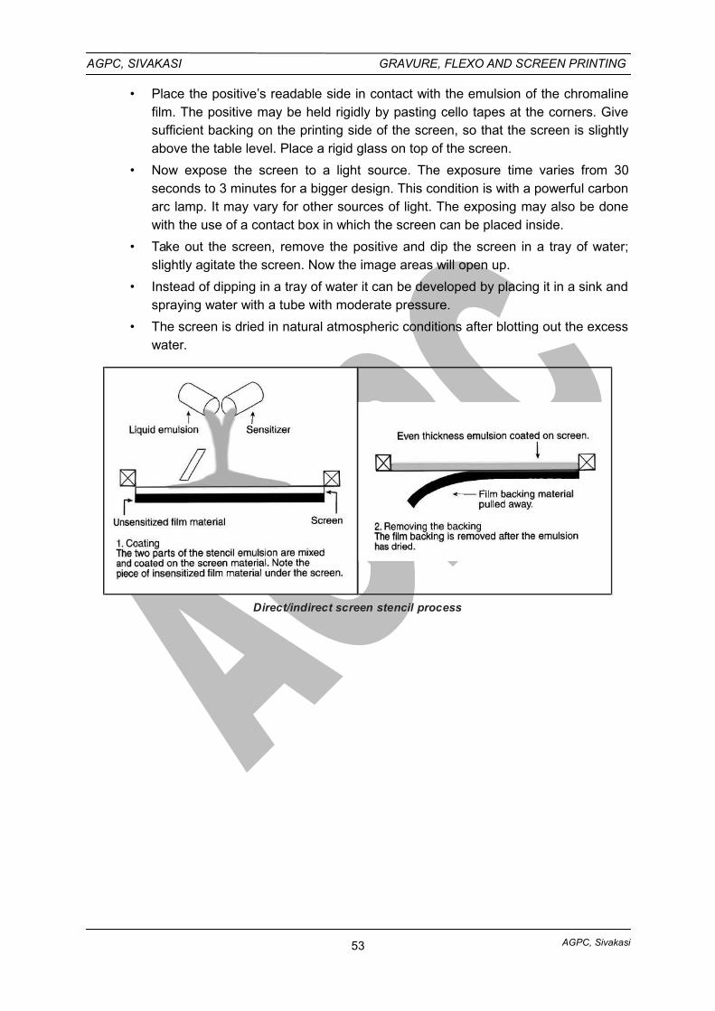
AGPC, Sivakasi
AGPC, SIVAKASI GRAVURE, FLEXO AND SCREEN PRINTING
• Place the positive’s readable side in contact with the emulsion of the chromalinefilm. The positive may be held rigidly by pasting cello tapes at the corners. Givesufficient backing on the printing side of the screen, so that the screen is slightlyabove the table level. Place a rigid glass on top of the screen.
• Now expose the screen to a light source. The exposure time varies from 30seconds to 3 minutes for a bigger design. This condition is with a powerful carbonarc lamp. It may vary for other sources of light. The exposing may also be donewith the use of a contact box in which the screen can be placed inside.
• Take out the screen, remove the positive and dip the screen in a tray of water;slightly agitate the screen. Now the image areas will open up.
• Instead of dipping in a tray of water it can be developed by placing it in a sink andspraying water with a tube with moderate pressure.
• The screen is dried in natural atmospheric conditions after blotting out the excesswater.
Direct/indirect screen stencil process
53
AGPC, Sivakasi
AGPC, SIVAKASI GRAVURE, FLEXO AND SCREEN PRINTING
UNIT: II - IMAGE CARRIER PREPARATION
Part – A (2 Marks Questions)
1. State the type of image carrier used for flexographic printing.
Relief image carriers.
2. What are rubber plates?
Rubber plates made from natural and synthetic rubber were the first type of plates
developed for flexographic printing. Rubber plates are prepared from mould or matrix. The
mould is prepared from the original relief metal plate.
3. What do you mean by relief depth?
The distance between the floor and face of the flexographic (relief) plate is known as
the relief depth.
4. What is matrix?
A matrix is a mould made from an engraving or a metal relief master into which
softened rubber is pressed for rubber plates preparation. Matrix is composed of
thermoplastic resin and cellulose material.
5. State the purpose of back exposure given to flexo plates.
Back exposure is done to harden or cure the base of the flexo plate. Back exposure
determines floor thickness and relief depth of the flexo plate.
6. What do you mean by face & floor of the plate?
Face: The physical past of the flexographic printing plate that holds the image to be
printed is called the face of the plate.
Floor: The non image area of the flexographic plate is called the floor of the plate.
7. What is vulcanization?
The process in which gum is cured and changing its physical properties to rubber.
8. Mention the layers of photopolymer plates.
i. Stable base / Substrate layer.
ii. Light sensitive photopolymer plates.
iii. Removable cover sheet layer.
9. State the type of image carrier used for gravure printing.
Recessed or sunken image carrier.
10. What are the various methods of copper plating the cylinder?
a) The thin copper layer method (approximately 80 µm of copper)
b) The ballard skin method (removable copper skin of 80 to 100 µm)
c) The heavy copper plating method (approximately 320 µm of copper)
54
AGPC, Sivakasi
AGPC, SIVAKASI GRAVURE, FLEXO AND SCREEN PRINTING
11. Name the various layers of imaged copper cylinder.
Stainless steel base cylinder, nickel layer, base copper layer, engraving copper layer,
chromium layer.
12. What is gravure scope?
A microscope used to examine engraved gravure cylinder or Anilox roller cell as a
means of evaluating cell depth, the cell opening, and cell wall thickness.
13. What is carbon tissue?
Carbon tissue is light sensitive material attached to gravure cylinders, used as a
resist during the chemical etching process. Carbon tissue consists of layers of gelatin, dye,
photosensitive material, and a paper or plastic backing.
14. What is electroplating process?
The electro deposition of an adherent metallic coating on an electrode for the
purpose of securing a surface with properties or dimension different from those of base
material.
15. Define etching.
This is the process of dissolving unevenly a part of the surface of a metal using an
acid or other corrosive substance.
16. What is sleeve?
This is tubular part of a base cylinder, which can be mounted on a shaft.
17. What is the chemical used for etching gravure cylinder?
Ferric chloride solution.
18. State the purpose of chrome plating gravure cylinder.
A thin chrome plating is done over the copper cylinder in order to protect the cylinder
surface from wear and tear caused by the wiping action of doctor blade.
19. Name the various halftone processes available for gravure cylinder preparation.
i) Double positive system halftone gravure.
ii) Halftone gravure process or direct transfer process.
20. What are screen fabrics?
In screen-printing, screen fabric is the material used to make the screen to which the
stencil is attached and through which the ink is transferred. Screen fabrics include such
substances as silk, polyester fibers, nylon, and metal wires.
21. What is direct stencil?
A light –sensitive liquid emulsion that squeezed into the screen fabric and becomes
stencil when contact exposing and processing are done on the screen.
55
AGPC, Sivakasi
AGPC, SIVAKASI GRAVURE, FLEXO AND SCREEN PRINTING
22. What is emulsion?
A solution that contains light-sensitive diazo or bichromatic components used in thedirect stencil method in screen-printing.
23. What is indirect film or transfer film?
A light sensitive gelatin emulsion coated on a polyester or plastic carrier sheet that isexposed to a film positive and chemically processed into a stencil before being adhered tothe stretched screen fabric. After the stencil is dry, the carrier sheet is removed.
24. What is mesh?
The open space between the woven threads of screen-printing fabric through whichthe ink passes during printing.
25. What is photo stencil?
A stencil in which image and non-image areas are produced photographically iscalled a photo stencil.
26. What is a scoop coater?
A tool for coating screen-printing fabrics with photosensitive emulsions for makingphoto stencils.
27. What is serigraphy?
A fine art screen-printing reproduction of an original artwork is called serigraphy.
28. What is tension meter?
A precision instrument used to measure the surface tension of the stretched screenfabrics.
29. State the thickness of different range of photopolymer plates available.
Single layer sheet photopolymer plates are available in thickness fro 0.76mm to 6.35mm. Thicker sheet photopolymer plates are available in thickness from 4 to 5 mm.
30. What are image carriers?
Any plate, film, cylinder or other surface which contains an image are called imagecarriers. Image carriers receive ink, and transfers it to the substrate to be printed.
Eg: Gravure cylinders, Flexo photopolymer plates, screen stencils, offset plates,letterpress blocks.
31. What is integral shaft and mandrel shaft?
Integral Shaft: A cylinder base design in which the supporting shaft is permanentlyattached to the printing cylinder.
Mandrel Shaft : A cylinder that is not permanently mounted on a shaft and can beremoved.
32. What is engraving?
Engraving is a printing principle whereby an image area lies beneath the surface of aplate and the non image areas exist on the plate surface. Ink is applied to the plate and then
56
AGPC, Sivakasi
AGPC, SIVAKASI GRAVURE, FLEXO AND SCREEN PRINTING
wiped from the surface, leaving the ink in the recessed image areas. Pressure applied to thesubstrate transfers the image.
33. State the advantages of electron beam engraving.
This technology, working on a vacuum, could engrave cells at speeds upto 1, 50,000
cells per second in a copper image carrier using digital information as input.
Part – B (3 Marks Questions)
1. State the various image carriers used for Flexographic printing.
a. Rubber Plates
b. Photopolymer plates
i. Sheet Photopolymer plates
ii. Liquid photopolymer plates
c. Laser – engraved rubber plates or rubber rollers
d. Laser engraving on polymer plates
e. Computer to photopolymer plates.
2. What are photopolymer plates?
Photopolymer plates are made from light – sensitive polymers (plastics). When they
are exposed to light, they undergo polymerization, or the chemical conversion of may small
molecules into long – chain molecules. The result is that they will be harder and more
insoluble in exposed image areas and become softer in unexposed non image areas.
There are two basic types of photopolymer plates used in Flexographic plate making
– sheet photopolymer plates and liquid photopolymer plates.
3. State the purpose of post exposure given to flexo plates.
After washing off the plate has to be dried thoroughly in order to evaporate any wash
– off agent that has penetrated relief layer. Post exposure is done to harden all parts of relief
completely. In this state, the plate has a sticky surface, on which dust and dirt would collect.
This stickness disappears as a result of exposure to UV- light or after immersion in a
bromine solution.
4. What are the various cylinder preparation methods available for gravure printing?
a. Conventional or carbon tissue or diffusion-etch method
b. Halftone Process
i. Double positive system halftone method
ii. Halftone gravure or direct transfer process
c. Electromechanical engraving process
d. Direct digital (Computer to cylinder for gravure printing) engraving process
e. Laser engraving process
f. Electron beam engraving process
57
AGPC, Sivakasi
AGPC, SIVAKASI GRAVURE, FLEXO AND SCREEN PRINTING
5. What are the various gravure cell configurations available?
Conventional Process - Cells having the same width but varied depth
Halftone gravure or direct transfer process - Cells having the same depth but
varied width
Electromechanical engraving Process - Cells having the varied width and varied
depth.
6. What is Ballard skin copper plating?
This method is also a thin layer copper deposition process (one – time use of the
engraving copper layer). The base copper layer is electrically covered with a removable
copper layer (80 to 100 µm), where by a special layer between base copper and Ballard skin
ensures that the Ballard skin can be peeled off from the gravure cylinder after printing. The
Ballard skin method is employed in approximately 45% of cases.
7. State the advantages of laser gravure engraving process.
i. Laser engraving opens new doors for gravure printing.
ii. The real advantage of this process is the speed of 30,000 cells per second.
iii. The unwanted saw tooth effect with fine fonts can be reduced.
iv. There is also the possibility of working with frequency modulated screens withlaser engraving process.
v. The laser engraver is designed to be six times faster than the existingelectromechanical equipment.
8. What are the advantages of direct digital engraving?
In Direct digital engraving, all image corrections are done in the digital file, eliminating
the need to correct film and/or cylinders. This significantly reduces the time required for the
manufacturing cycle and produces consistent quality. A duplicate cylinder can be made from
the digital data, thus minimizing the variables inherent in the use of film.
9. What are the various screen stencils available for screen printing?
Following are the various types of screen printing stencils available and each having
its own methods of preparation.
1. The knife cut printing screen,
2. The photographic printing screen,
3. The washout or etched screen, and
4. The block art printing screen.
10. What is mesh count and mesh opening?
Mesh Count: The number of openings per linear inch in any given screen printing
fabric. The higher the number, the finer the weave of the screen fabric.
Mesh Opening: In screen printing, a measure of the distance across the space
between two parallel threads, expressed in microns.
58
AGPC, Sivakasi
AGPC, SIVAKASI GRAVURE, FLEXO AND SCREEN PRINTING
11. What is monofilament, and multifilament?
Monofilament: A single strand of synthetic fiber that is woven with others to form a
porous screen fabric.
Multifilament: Many fine threads twisted together to form a single thread of synthetic
fiber that is woven with others to form a porous screen fabric.
Part – C (10 Marks Questions)
1. Describe the structure of flexographic plate with diagrams.
2. How will you prepare flexographic plates by laser engraving method?
3. Explain the steps involved in preparation of rubber plates with necessary diagrams.
4. Describe the steps involved in preparation of sheet photopolymer plates with suitable
sketches.
5. Explain the steps involved in liquid photopolymer plates preparation with suitable
diagrams.
6. Describe the process sequence for the preparation of copper cylinder.
7. Explain the various methods of copper plating the gravure cylinder.
8. Explain the steps involved in preparation of gravure cylinder by carbon tissue method with
necessary diagrams.
9. Explain the steps involved in electromechanical engraving of gravure cylinders with
necessary diagrams.
10. How will you prepare gravure cylinder by laser engraving process?
11. Explain the preparation of screen printing stencils by direct method with sketches.
12. Describe the steps involved in preparation of screen stencils by indirect method with
necessary diagrams.
13. How will you prepare screen-printing stencils by Direct / Indirect method. Support your
answer with diagrams.
14. Write notes on screen fabrics used for stencil preparation.
GLOSSARY
Computer-to-Sleeve (CTS)
A system where the plate is mounted on a sleeve and imaged in the round directlyfrom a computer system using laser ablation.
Cure
The process of hardening a heat-set or photoreactive material. For examplehardening photopolymers requires exposing the photoinitiator to UV light.
Deep-relief Powder Molding (DRPM)
59
AGPC, Sivakasi
AGPC, SIVAKASI GRAVURE, FLEXO AND SCREEN PRINTING
The rubber plate-making process where the finished plate relief is more than 0.125".
Matrix
An intermediate mold, made from an engraving or type form, from which a rubberplate is subsequently molded.
Photopolymer Plate
A flexible, relief-printing plate, used in flexography, made of either precast sheet orliquid light-sensitive polymers. Photopolymer plates require exposure to UV light during theplatemaking process.
Vulcanization
A curing process to change the physical properties of a rubber.
60
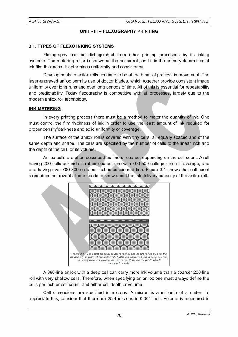
AGPC, Sivakasi
AGPC, SIVAKASI GRAVURE, FLEXO AND SCREEN PRINTING
UNIT - III – FLEXOGRAPHY PRINTING
3.1. TYPES OF FLEXO INKING SYSTEMS
Flexography can be distinguished from other printing processes by its inkingsystems. The metering roller is known as the anilox roll, and it is the primary determiner ofink film thickness. It determines uniformity and consistency.
Developments in anilox rolls continue to be at the heart of process improvement. Thelaser-engraved anilox permits use of doctor blades, which together provide consistent imageuniformity over long runs and over long periods of time. All of this is essential for repeatabilityand predictability. Today flexography is competitive with all processes, largely due to themodern anilox roll technology.
INK METERING
In every printing process there must be a method to meter the quantity of ink. Onemust control the film thickness of ink in order to use the least amount of ink required forproper density/darkness and solid uniformity or coverage.
The surface of the anilox roll is covered with tiny cells, all equally spaced and of thesame depth and shape. The cells are specified by the number of cells to the linear inch andthe depth of the cell, or its volume.
Anilox cells are often described as fine or coarse, depending on the cell count. A rollhaving 200 cells per inch is rather coarse, one with 400-500 cells per inch is average, andone having over 700-800 cells per inch is considered fine. Figure 3.1 shows that cell countalone does not reveal all one needs to know about the ink delivery capacity of the anilox roll.
Figure 3.1 - Cell count alone does not reveal all one needs to know about theink delivery capacity of the anilox roll. A 360-line anilox roll with a deep cell (top)
can carry more ink volume than a coarser 200- line roll (bottom) withvery shallow cells.
A 360-line anilox with a deep cell can carry more ink volume than a coarser 200-lineroll with very shallow cells. Therefore, when specifying an anilox one must always define thecells per inch or cell count, and either cell depth or volume.
Cell dimensions are specified in microns. A micron is a millionth of a meter. Toappreciate this, consider that there are 25.4 microns in 0.001 inch. Volume is measured in
70
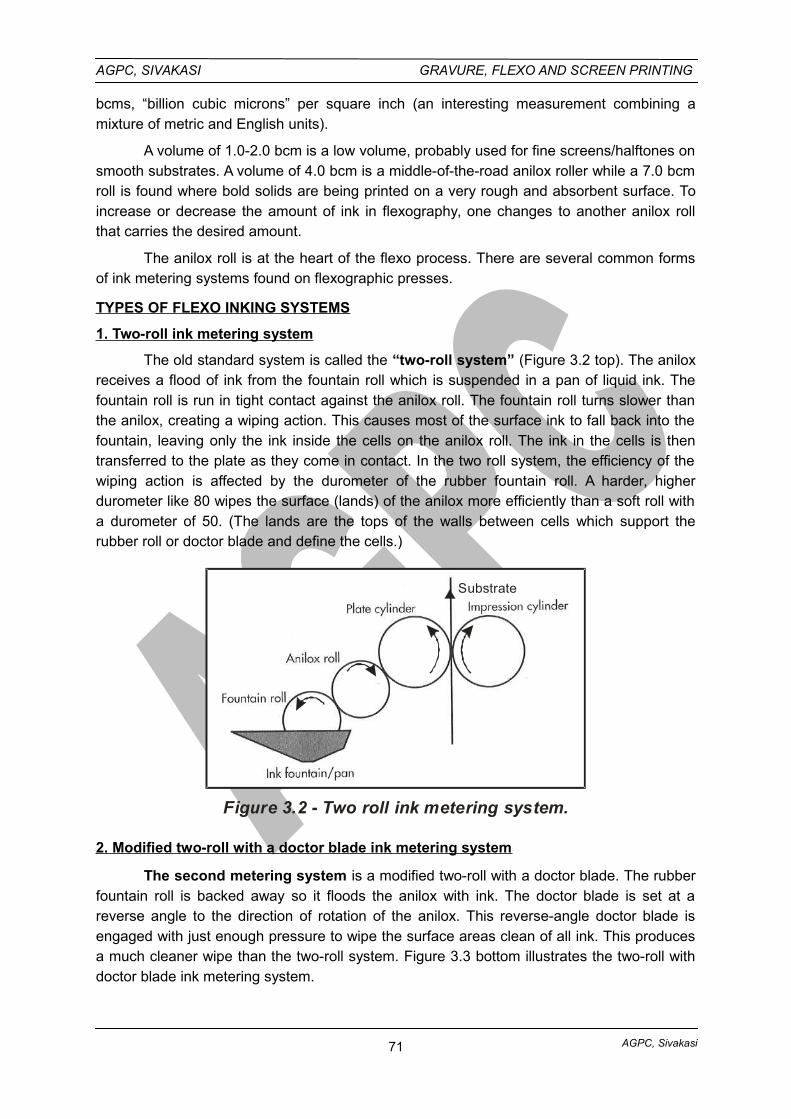
AGPC, Sivakasi
AGPC, SIVAKASI GRAVURE, FLEXO AND SCREEN PRINTING
bcms, “billion cubic microns” per square inch (an interesting measurement combining amixture of metric and English units).
A volume of 1.0-2.0 bcm is a low volume, probably used for fine screens/halftones onsmooth substrates. A volume of 4.0 bcm is a middle-of-the-road anilox roller while a 7.0 bcmroll is found where bold solids are being printed on a very rough and absorbent surface. Toincrease or decrease the amount of ink in flexography, one changes to another anilox rollthat carries the desired amount.
The anilox roll is at the heart of the flexo process. There are several common formsof ink metering systems found on flexographic presses.
TYPES OF FLEXO INKING SYSTEMS
1. Two-roll ink metering system
The old standard system is called the “two-roll system” (Figure 3.2 top). The aniloxreceives a flood of ink from the fountain roll which is suspended in a pan of liquid ink. Thefountain roll is run in tight contact against the anilox roll. The fountain roll turns slower thanthe anilox, creating a wiping action. This causes most of the surface ink to fall back into thefountain, leaving only the ink inside the cells on the anilox roll. The ink in the cells is thentransferred to the plate as they come in contact. In the two roll system, the efficiency of thewiping action is affected by the durometer of the rubber fountain roll. A harder, higherdurometer like 80 wipes the surface (lands) of the anilox more efficiently than a soft roll witha durometer of 50. (The lands are the tops of the walls between cells which support therubber roll or doctor blade and define the cells.)
Substrate
Figure 3.2 - Two roll ink metering system.
2. Modified two-roll with a doctor blade ink metering system
The second metering system is a modified two-roll with a doctor blade. The rubberfountain roll is backed away so it floods the anilox with ink. The doctor blade is set at areverse angle to the direction of rotation of the anilox. This reverse-angle doctor blade isengaged with just enough pressure to wipe the surface areas clean of all ink. This producesa much cleaner wipe than the two-roll system. Figure 3.3 bottom illustrates the two-roll withdoctor blade ink metering system.
71
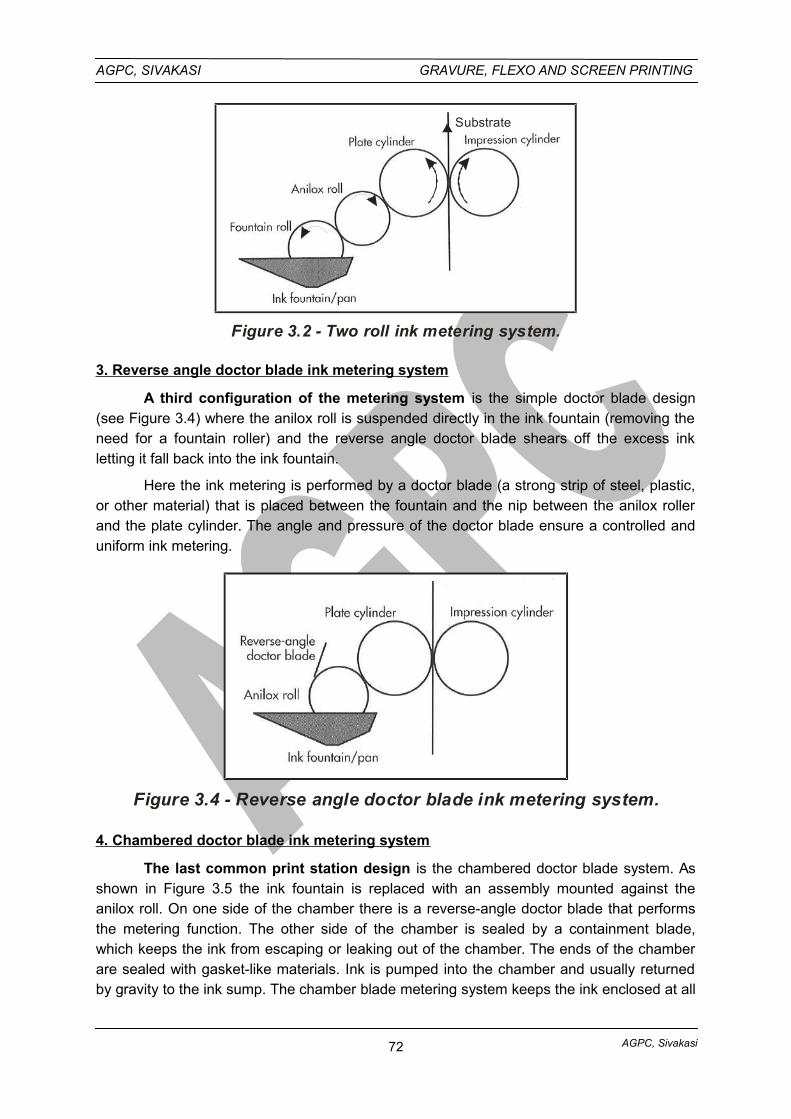
AGPC, Sivakasi
AGPC, SIVAKASI GRAVURE, FLEXO AND SCREEN PRINTING
Substrate
Figure 3.2 - Two roll ink metering system.
3. Reverse angle doctor blade ink metering system
A third configuration of the metering system is the simple doctor blade design(see Figure 3.4) where the anilox roll is suspended directly in the ink fountain (removing theneed for a fountain roller) and the reverse angle doctor blade shears off the excess inkletting it fall back into the ink fountain.
Here the ink metering is performed by a doctor blade (a strong strip of steel, plastic,or other material) that is placed between the fountain and the nip between the anilox rollerand the plate cylinder. The angle and pressure of the doctor blade ensure a controlled anduniform ink metering.
Figure 3.4 - Reverse angle doctor blade ink metering system.
4. Chambered doctor blade ink metering system
The last common print station design is the chambered doctor blade system. Asshown in Figure 3.5 the ink fountain is replaced with an assembly mounted against theanilox roll. On one side of the chamber there is a reverse-angle doctor blade that performsthe metering function. The other side of the chamber is sealed by a containment blade,which keeps the ink from escaping or leaking out of the chamber. The ends of the chamberare sealed with gasket-like materials. Ink is pumped into the chamber and usually returnedby gravity to the ink sump. The chamber blade metering system keeps the ink enclosed at all
72
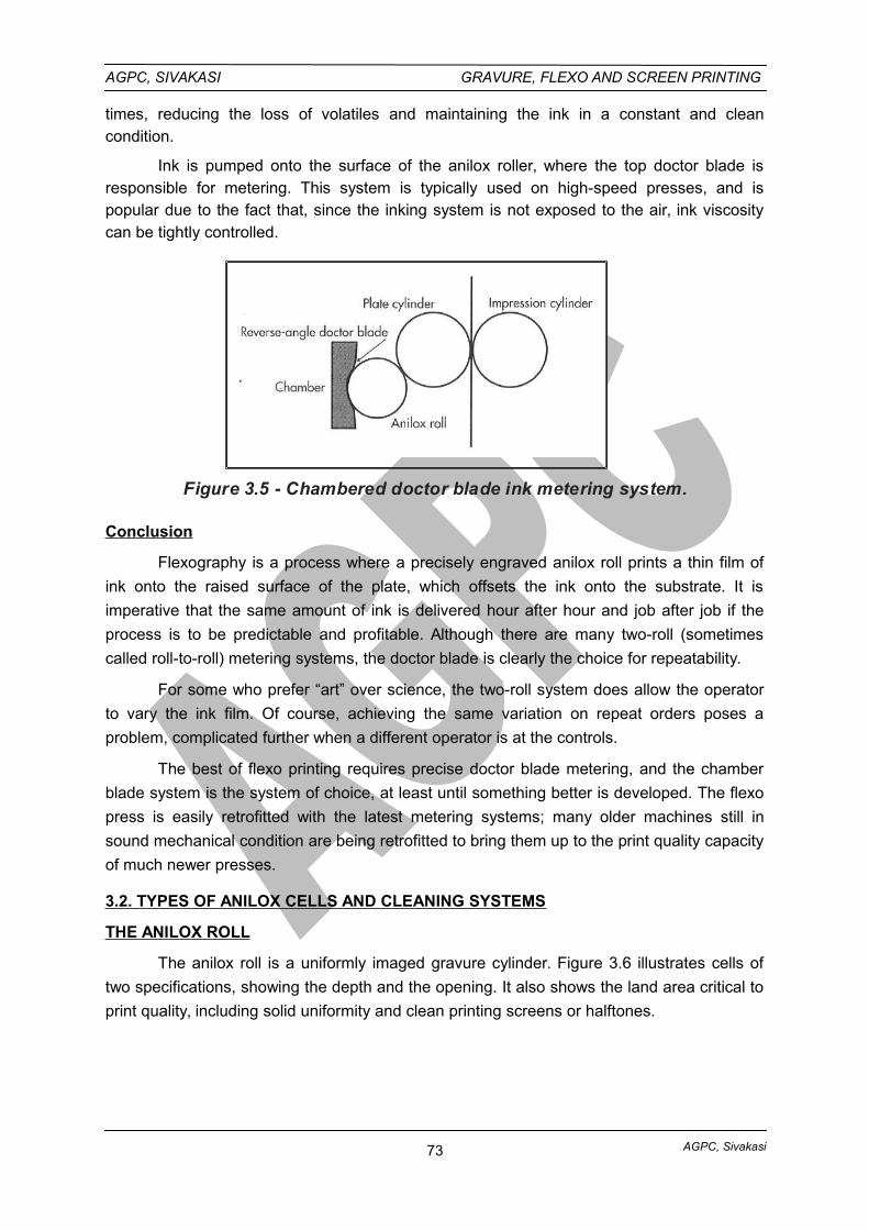
AGPC, Sivakasi
AGPC, SIVAKASI GRAVURE, FLEXO AND SCREEN PRINTING
times, reducing the loss of volatiles and maintaining the ink in a constant and cleancondition.
Ink is pumped onto the surface of the anilox roller, where the top doctor blade isresponsible for metering. This system is typically used on high-speed presses, and ispopular due to the fact that, since the inking system is not exposed to the air, ink viscositycan be tightly controlled.
Figure 3.5 - Chambered doctor blade ink metering system.
Conclusion
Flexography is a process where a precisely engraved anilox roll prints a thin film of
ink onto the raised surface of the plate, which offsets the ink onto the substrate. It is
imperative that the same amount of ink is delivered hour after hour and job after job if the
process is to be predictable and profitable. Although there are many two-roll (sometimes
called roll-to-roll) metering systems, the doctor blade is clearly the choice for repeatability.
For some who prefer “art” over science, the two-roll system does allow the operator
to vary the ink film. Of course, achieving the same variation on repeat orders poses a
problem, complicated further when a different operator is at the controls.
The best of flexo printing requires precise doctor blade metering, and the chamber
blade system is the system of choice, at least until something better is developed. The flexo
press is easily retrofitted with the latest metering systems; many older machines still in
sound mechanical condition are being retrofitted to bring them up to the print quality capacity
of much newer presses.
3.2. TYPES OF ANILOX CELLS AND CLEANING SYSTEMS
THE ANILOX ROLL
The anilox roll is a uniformly imaged gravure cylinder. Figure 3.6 illustrates cells of
two specifications, showing the depth and the opening. It also shows the land area critical to
print quality, including solid uniformity and clean printing screens or halftones.
73
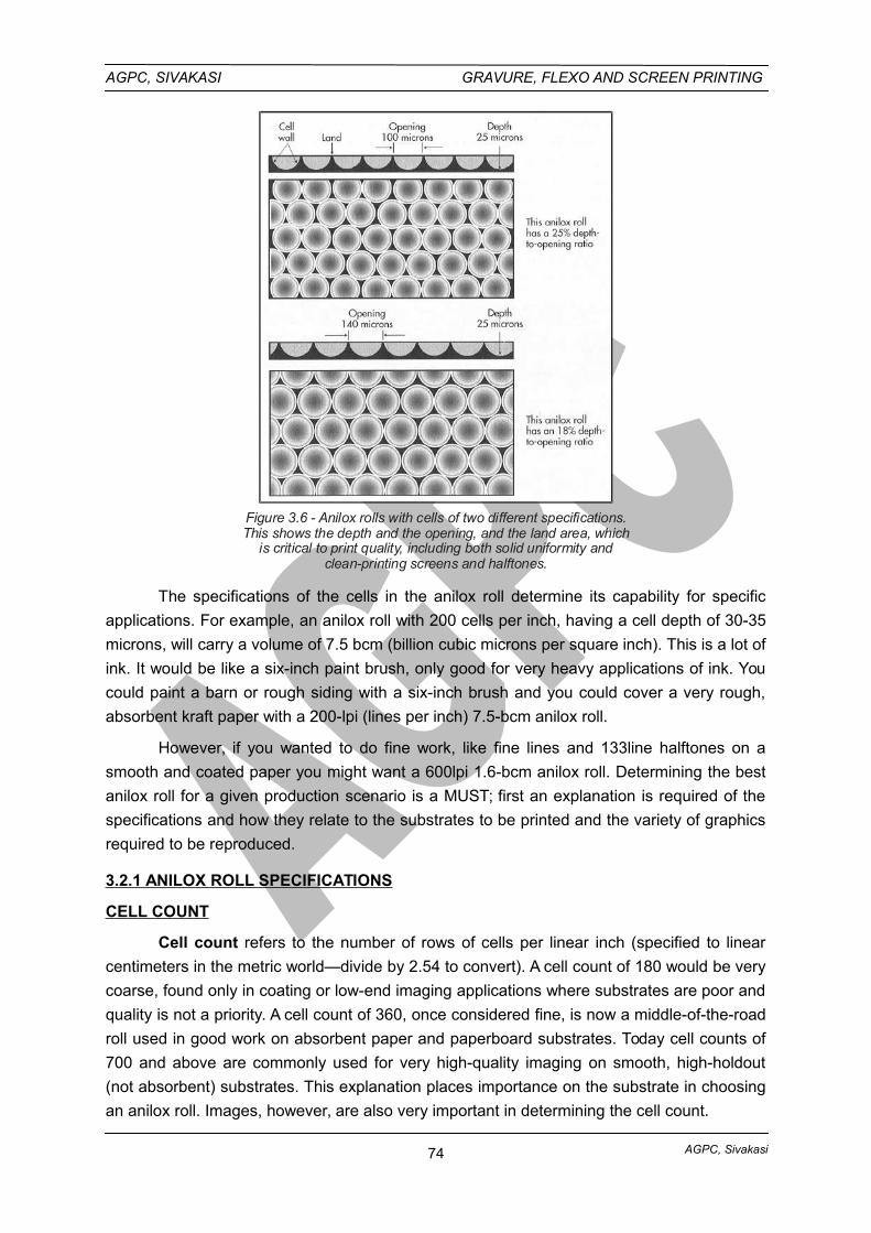
AGPC, Sivakasi
AGPC, SIVAKASI GRAVURE, FLEXO AND SCREEN PRINTING
Figure 3.6 - Anilox rolls with cells of two different specifications.This shows the depth and the opening, and the land area, which
is critical to print quality, including both solid uniformity andclean-printing screens and halftones.
The specifications of the cells in the anilox roll determine its capability for specific
applications. For example, an anilox roll with 200 cells per inch, having a cell depth of 30-35
microns, will carry a volume of 7.5 bcm (billion cubic microns per square inch). This is a lot of
ink. It would be like a six-inch paint brush, only good for very heavy applications of ink. You
could paint a barn or rough siding with a six-inch brush and you could cover a very rough,
absorbent kraft paper with a 200-lpi (lines per inch) 7.5-bcm anilox roll.
However, if you wanted to do fine work, like fine lines and 133line halftones on a
smooth and coated paper you might want a 600lpi 1.6-bcm anilox roll. Determining the best
anilox roll for a given production scenario is a MUST; first an explanation is required of the
specifications and how they relate to the substrates to be printed and the variety of graphics
required to be reproduced.
3.2.1 ANILOX ROLL SPECIFICATIONS
CELL COUNT
Cell count refers to the number of rows of cells per linear inch (specified to linear
centimeters in the metric world—divide by 2.54 to convert). A cell count of 180 would be very
coarse, found only in coating or low-end imaging applications where substrates are poor and
quality is not a priority. A cell count of 360, once considered fine, is now a middle-of-the-road
roll used in good work on absorbent paper and paperboard substrates. Today cell counts of
700 and above are commonly used for very high-quality imaging on smooth, high-holdout
(not absorbent) substrates. This explanation places importance on the substrate in choosing
an anilox roll. Images, however, are also very important in determining the cell count.
74
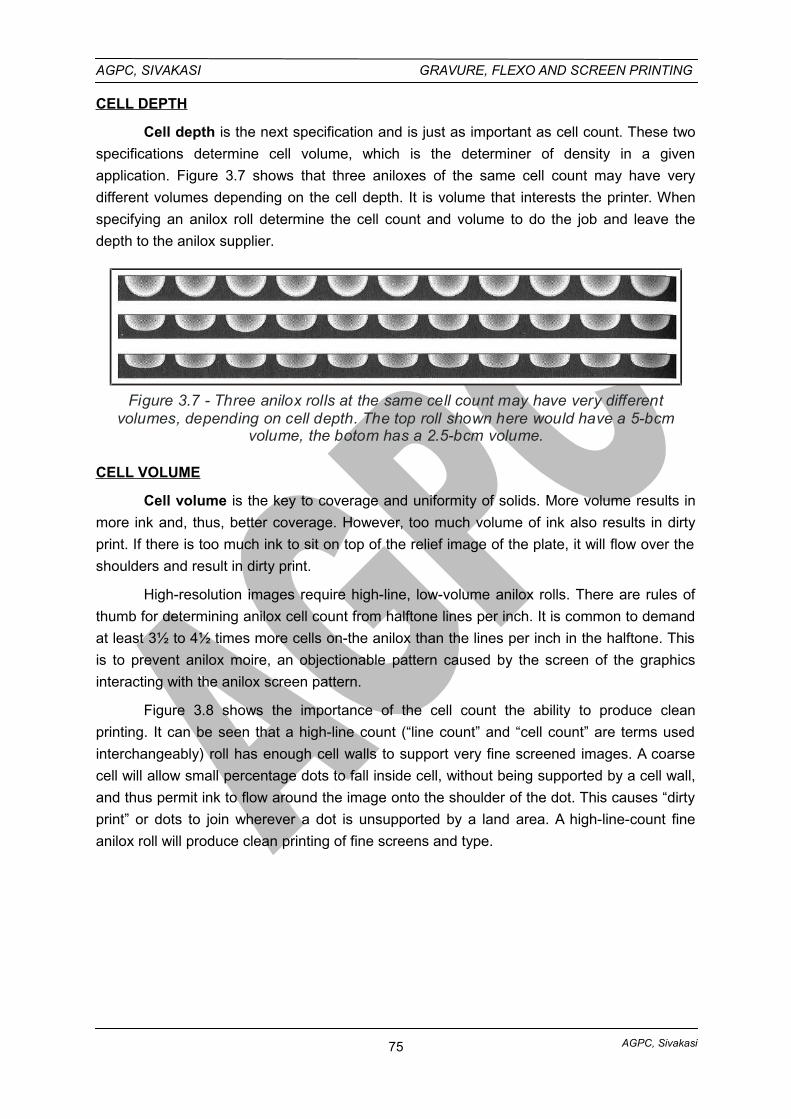
AGPC, Sivakasi
AGPC, SIVAKASI GRAVURE, FLEXO AND SCREEN PRINTING
CELL DEPTH
Cell depth is the next specification and is just as important as cell count. These two
specifications determine cell volume, which is the determiner of density in a given
application. Figure 3.7 shows that three aniloxes of the same cell count may have very
different volumes depending on the cell depth. It is volume that interests the printer. When
specifying an anilox roll determine the cell count and volume to do the job and leave the
depth to the anilox supplier.
Figure 3.7 - Three anilox rolls at the same cell count may have very differentvolumes, depending on cell depth. The top roll shown here would have a 5-bcm
volume, the botom has a 2.5-bcm volume.
CELL VOLUME
Cell volume is the key to coverage and uniformity of solids. More volume results in
more ink and, thus, better coverage. However, too much volume of ink also results in dirty
print. If there is too much ink to sit on top of the relief image of the plate, it will flow over the
shoulders and result in dirty print.
High-resolution images require high-line, low-volume anilox rolls. There are rules of
thumb for determining anilox cell count from halftone lines per inch. It is common to demand
at least 3½ to 4½ times more cells on-the anilox than the lines per inch in the halftone. This
is to prevent anilox moire, an objectionable pattern caused by the screen of the graphics
interacting with the anilox screen pattern.
Figure 3.8 shows the importance of the cell count the ability to produce clean
printing. It can be seen that a high-line count (“line count” and “cell count” are terms used
interchangeably) roll has enough cell walls to support very fine screened images. A coarse
cell will allow small percentage dots to fall inside cell, without being supported by a cell wall,
and thus permit ink to flow around the image onto the shoulder of the dot. This causes “dirty
print” or dots to join wherever a dot is unsupported by a land area. A high-line-count fine
anilox roll will produce clean printing of fine screens and type.
75
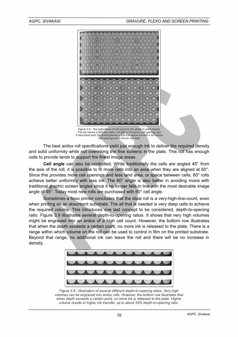
AGPC, Sivakasi
AGPC, SIVAKASI GRAVURE, FLEXO AND SCREEN PRINTING
Figure 3.8 - The importance of cell count to the ability to print cleanly.The top shows a 900-line anilox roll with a 25-micron cell opening and
3-microncell wall; the bottomshows a 550-line anilox roll with a 42-microncell opening and 4-micron cell wall.
The best anilox roll specifications yield just enough ink to deliver the required densityand solid uniformity while not overinking the fine screens in the plate. This roll has enoughcells to provide lands to support the finest image areas.
Cell angle can also be controlled. While traditionally the cells are angled 45° fromthe axis of the roll, it is possible to fit more cells into an area when they are aligned at 60°.Since this provides more cell openings and less land area, or space between cells, 60° rollsachieve better uniformity with less ink. The 60° angle is also better in avoiding moire withtraditional graphic screen angles since it no longer falls in line with the most desirable imageangle of 45°. Today most new rolls are purchased with 60° cell angle.
Sometimes a flexo printer concludes that the ideal roll is a very-high-line-count, evenwhen printing on an absorbent substrate. The all that is needed is very deep cells to achievethe required volume. This introduces one last concept to be considered, depth-to-openingratio. Figure 3.9 illustrates several depth-to-opening ratios. It shows that very high volumesmight be engraved into an anilox of a high cell count. However, the bottom row illustratesthat when the depth exceeds a certain point, no more ink is released to the plate. There is arange within which volume on the roll can be used to control in film on the printed substrate.Beyond that range, no additional ink can leave the roll and there will be no increase indensity.
Figure 3.9 - Illustration of several different depth-to-opening ratios. Very highvolumes can be engraved into anilox rolls. However, the bottom row illustrates that
when depth exceeds a certain point, no more ink is released to the plate. Highervolume results in higher ink transfer, up to about 35% depth-to-opening ratio.
76
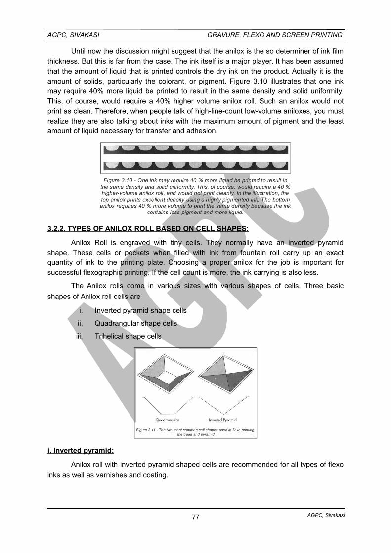
AGPC, Sivakasi
AGPC, SIVAKASI GRAVURE, FLEXO AND SCREEN PRINTING
Until now the discussion might suggest that the anilox is the so determiner of ink filmthickness. But this is far from the case. The ink itself is a major player. It has been assumedthat the amount of liquid that is printed controls the dry ink on the product. Actually it is theamount of solids, particularly the colorant, or pigment. Figure 3.10 illustrates that one inkmay require 40% more liquid be printed to result in the same density and solid uniformity.This, of course, would require a 40% higher volume anilox roll. Such an anilox would notprint as clean. Therefore, when people talk of high-line-count low-volume aniloxes, you mustrealize they are also talking about inks with the maximum amount of pigment and the leastamount of liquid necessary for transfer and adhesion.
Figure 3.10 - One ink may require 40 % more liquid be printed to result inthe same density and solid uniformity. This, of course, would require a 40 %higher-volume anilox roll, and would not print cleanly. In the illustration, thetop anilox prints excellent density using a highly pigmented ink. The bottomanilox requires 40 % more volume to print the same density because the ink
contains less pigment and more liquid.
3.2.2. TYPES OF ANILOX ROLL BASED ON CELL SHAPES:
Anilox Roll is engraved with tiny cells. They normally have an inverted pyramidshape. These cells or pockets when filled with ink from fountain roll carry up an exactquantity of ink to the printing plate. Choosing a proper anilox for the job is important forsuccessful flexographic printing. If the cell count is more, the ink carrying is also less.
The Anilox rolls come in various sizes with various shapes of cells. Three basic
shapes of Anilox roll cells are
i. Inverted pyramid shape cells
ii. Quadrangular shape cells
iii. Trihelical shape cells
Figure 3.11 - The two most common cell shapes used in flexo printing,the quad and pyramid
i. Inverted pyramid:
Anilox roll with inverted pyramid shaped cells are recommended for all types of flexo
inks as well as varnishes and coating.
77
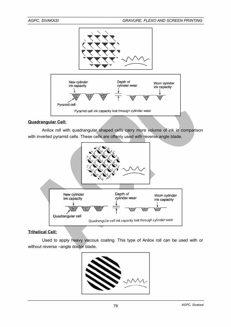
AGPC, Sivakasi
AGPC, SIVAKASI GRAVURE, FLEXO AND SCREEN PRINTING
Quadrangular Cell:
Anilox roll with quadrangular shaped cells carry more volume of ink in comparison
with inverted pyramid cells. These cells are oftenly used with reverse angle blade.
Trihelical Cell:
Used to apply heavy viscous coating. This type of Anilox roll can be used with or
without reverse –angle doctor blade.
78
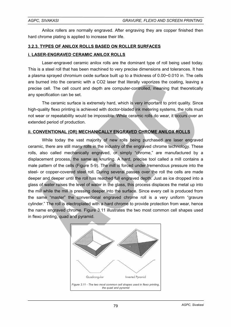
AGPC, Sivakasi
AGPC, SIVAKASI GRAVURE, FLEXO AND SCREEN PRINTING
Anilox rollers are normally engraved. After engraving they are copper finished then
hard chrome plating is applied to increase their life.
3.2.3. TYPES OF ANILOX ROLLS BASED ON ROLLER SURFACES
i. LASER-ENGRAVED CERAMIC ANILOX ROLLS
Laser-engraved ceramic anilox rolls are the dominant type of roll being used today.
This is a steel roll that has been machined to very precise dimensions and tolerances. It has
a plasma sprayed chromium oxide surface built up to a thickness of 0.00~0.010 in. The cells
are burned into the ceramic with a CO2 laser that literally vaporizes the coating, leaving a
precise cell. The cell count and depth are computer-controlled, meaning that theoretically
any specification can be set.
The ceramic surface is extremely hard, which is very important to print quality. Since
high-quality flexo printing is achieved with doctor-bladed ink metering systems, the rolls must
not wear or repeatability would be impossible. While ceramic rolls do wear, it occurs over an
extended period of production.
ii. CONVENTIONAL (OR) MECHANICALLY ENGRAVED CHROME ANILOX ROLLS
While today the vast majority of new rolls being purchased are laser engraved
ceramic, there are still many rolls in the industry of the engraved chrome technology. These
rolls, also called mechanically engraved, or simply “chrome,” are manufactured by a
displacement process, the same as knurling. A hard, precise tool called a mill contains a
male pattern of the cells (Figure 5-9). The mill is forced under tremendous pressure into the
steel- or copper-covered steel roll. During several passes over the roll the cells are made
deeper and deeper until the roll has reached full engraved depth. Just as ice dropped into a
glass of water raises the level of water in the glass, this process displaces the metal up into
the mill while the mill is pressing deeper into the surface. Since every cell is produced from
the same “master” the conventional engraved chrome roll is a very uniform “gravure
cylinder.” The roll is electroplated with a hard chrome to provide protection from wear, hence
the name engraved chrome. Figure 3.11 illustrates the two most common cell shapes used
in flexo printing, quad and pyramid.
Figure 3.11 - The two most common cell shapes used in flexo printing,the quad and pyramid
79
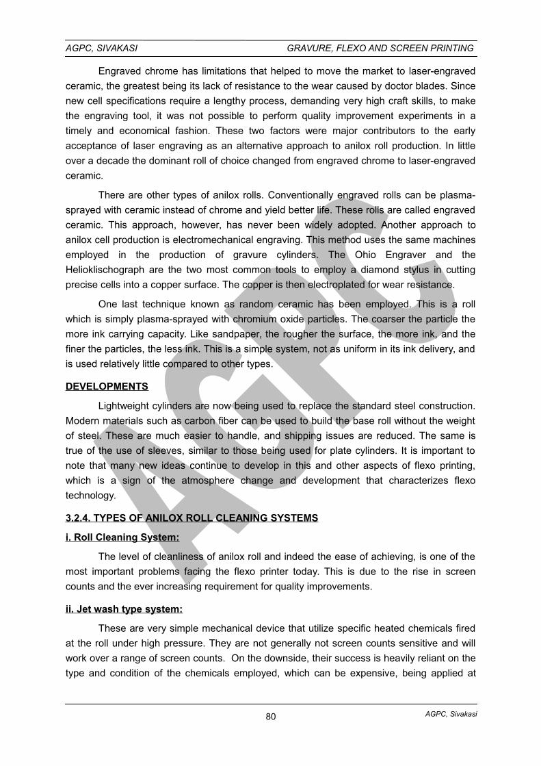
AGPC, Sivakasi
AGPC, SIVAKASI GRAVURE, FLEXO AND SCREEN PRINTING
Engraved chrome has limitations that helped to move the market to laser-engraved
ceramic, the greatest being its lack of resistance to the wear caused by doctor blades. Since
new cell specifications require a lengthy process, demanding very high craft skills, to make
the engraving tool, it was not possible to perform quality improvement experiments in a
timely and economical fashion. These two factors were major contributors to the early
acceptance of laser engraving as an alternative approach to anilox roll production. In little
over a decade the dominant roll of choice changed from engraved chrome to laser-engraved
ceramic.
There are other types of anilox rolls. Conventionally engraved rolls can be plasma-
sprayed with ceramic instead of chrome and yield better life. These rolls are called engraved
ceramic. This approach, however, has never been widely adopted. Another approach to
anilox cell production is electromechanical engraving. This method uses the same machines
employed in the production of gravure cylinders. The Ohio Engraver and the
Helioklischograph are the two most common tools to employ a diamond stylus in cutting
precise cells into a copper surface. The copper is then electroplated for wear resistance.
One last technique known as random ceramic has been employed. This is a roll
which is simply plasma-sprayed with chromium oxide particles. The coarser the particle the
more ink carrying capacity. Like sandpaper, the rougher the surface, the more ink, and the
finer the particles, the less ink. This is a simple system, not as uniform in its ink delivery, and
is used relatively little compared to other types.
DEVELOPMENTS
Lightweight cylinders are now being used to replace the standard steel construction.
Modern materials such as carbon fiber can be used to build the base roll without the weight
of steel. These are much easier to handle, and shipping issues are reduced. The same is
true of the use of sleeves, similar to those being used for plate cylinders. It is important to
note that many new ideas continue to develop in this and other aspects of flexo printing,
which is a sign of the atmosphere change and development that characterizes flexo
technology.
3.2.4. TYPES OF ANILOX ROLL CLEANING SYSTEMS
i. Roll Cleaning System:
The level of cleanliness of anilox roll and indeed the ease of achieving, is one of the
most important problems facing the flexo printer today. This is due to the rise in screen
counts and the ever increasing requirement for quality improvements.
ii. Jet wash type system:
These are very simple mechanical device that utilize specific heated chemicals fired
at the roll under high pressure. They are not generally not screen counts sensitive and will
work over a range of screen counts. On the downside, their success is heavily reliant on the
type and condition of the chemicals employed, which can be expensive, being applied at
80
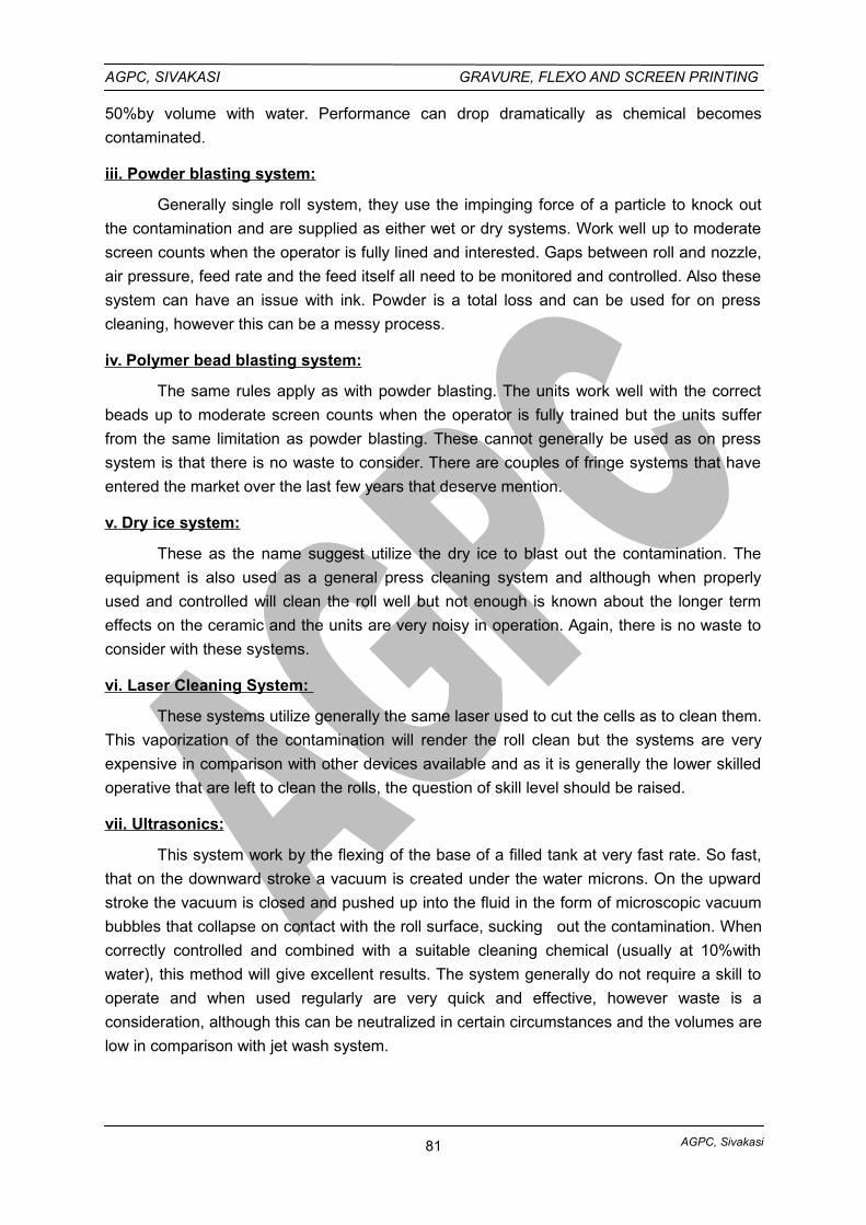
AGPC, Sivakasi
AGPC, SIVAKASI GRAVURE, FLEXO AND SCREEN PRINTING
50%by volume with water. Performance can drop dramatically as chemical becomes
contaminated.
iii. Powder blasting system:
Generally single roll system, they use the impinging force of a particle to knock out
the contamination and are supplied as either wet or dry systems. Work well up to moderate
screen counts when the operator is fully lined and interested. Gaps between roll and nozzle,
air pressure, feed rate and the feed itself all need to be monitored and controlled. Also these
system can have an issue with ink. Powder is a total loss and can be used for on press
cleaning, however this can be a messy process.
iv. Polymer bead blasting system:
The same rules apply as with powder blasting. The units work well with the correct
beads up to moderate screen counts when the operator is fully trained but the units suffer
from the same limitation as powder blasting. These cannot generally be used as on press
system is that there is no waste to consider. There are couples of fringe systems that have
entered the market over the last few years that deserve mention.
v. Dry ice system:
These as the name suggest utilize the dry ice to blast out the contamination. The
equipment is also used as a general press cleaning system and although when properly
used and controlled will clean the roll well but not enough is known about the longer term
effects on the ceramic and the units are very noisy in operation. Again, there is no waste to
consider with these systems.
vi. Laser Cleaning System:
These systems utilize generally the same laser used to cut the cells as to clean them.
This vaporization of the contamination will render the roll clean but the systems are very
expensive in comparison with other devices available and as it is generally the lower skilled
operative that are left to clean the rolls, the question of skill level should be raised.
vii. Ultrasonics:
This system work by the flexing of the base of a filled tank at very fast rate. So fast,
that on the downward stroke a vacuum is created under the water microns. On the upward
stroke the vacuum is closed and pushed up into the fluid in the form of microscopic vacuum
bubbles that collapse on contact with the roll surface, sucking out the contamination. When
correctly controlled and combined with a suitable cleaning chemical (usually at 10%with
water), this method will give excellent results. The system generally do not require a skill to
operate and when used regularly are very quick and effective, however waste is a
consideration, although this can be neutralized in certain circumstances and the volumes are
low in comparison with jet wash system.
81
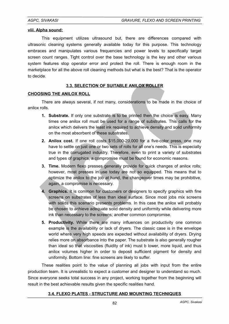
AGPC, Sivakasi
AGPC, SIVAKASI GRAVURE, FLEXO AND SCREEN PRINTING
viii. Alpha sound:
This equipment utilizes ultrasound but, there are differences compared with
ultrasonic cleaning systems generally available today for this purpose. This technology
embraces and manipulates various frequencies and power levels to specifically target
screen count ranges. Tight control over the base technology is the key and other various
system features stop operator error and protect the roll. There is enough room in the
marketplace for all the above roll cleaning methods but what is the best? That is the operator
to decide.
3.3. SELECTION OF SUITABLE ANILOX ROLLER
CHOOSING THE ANILOX ROLL
There are always several, if not many, considerations to be made in the choice ofanilox rolls.
1. Substrate. If only one substrate is to be printed then the choice is easy. Manytimes one anilox roll must be used for a range of substrates. This calls for theanilox which delivers the least ink required to achieve density and solid uniformityon the most absorbent of these substrates.
2. Anilox cost. If one roll costs $15,000-20,000 for a five-color press, one mayhave to settle on just one or two sets of rolls for all one’s needs. This is especiallytrue in the corrugated industry. Therefore, even to print a variety of substratesand types of graphics, a compromise must be found for economic reasons.
3. Time. Modern flexo presses generally provide for quick changes of anilox rolls;however, most presses in use today are not so equipped. This means that tooptimize the anilox to the job at hand, the changeover times may be prohibitive,again, a compromise is necessary.
4. Graphics. It is common for customers or designers to specify graphics with finescreens on substrates of less than ideal surface. Since most jobs mix screenswith solids this scenario presents problems. In this case the anilox will probablybe chosen to achieve adequate solid density and uniformity while delivering moreink than necessary to the screens; another common compromise.
5. Productivity. While there are many influences on productivity one commonexample is the availability or lack of dryers. The classic case is in the envelopeworld where very high speeds are expected without availability of dryers. Dryingrelies more on absorbance into the paper. The substrate is also generally rougherthan ideal so that viscosities (fluidity of ink) must b lower, more liquid, and thusanilox volumes higher in order to deposit sufficient pigment for density anduniformity. Bottom line: fine screens are likely to suffer.
These realities point to the value of planning all jobs with input from the entire
production team. It is unrealistic to expect a customer and designer to understand so much.
Since everyone seeks total success in any project, working together from the beginning will
result in the best achievable results given the specific realities hand.
3.4. FLEXO PLATES - STRUCTURE AND MOUNTING TECHNIQUES
82
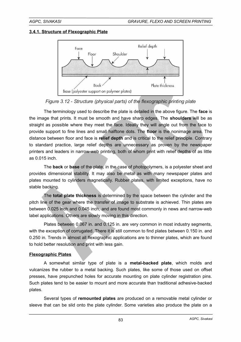
AGPC, Sivakasi
AGPC, SIVAKASI GRAVURE, FLEXO AND SCREEN PRINTING
3.4.1. Structure of Flexographic Plate
Figure 3.12 - Structure (physical parts) of the flexographic printing plate
The terminology used to describe the plate is detailed in the above figure. The face is
the image that prints. It must be smooth and have sharp edges. The shoulders will be as
straight as possible where they meet the face. Ideally they will angle out from the face to
provide support to fine lines and small halftone dots. The floor is the nonimage area. The
distance between floor and face is relief depth and is critical to the relief principle. Contrary
to standard practice, large relief depths are unnecessary as proven by the newspaper
printers and leaders in narrow-web printing, both of whom print with relief depths of as little
as 0.015 inch.
The back or base of the plate, in the case of photopolymers, is a polyester sheet and
provides dimensional stability. It may also be metal as with many newspaper plates and
plates mounted to cylinders magnetically. Rubber plates, with limited exceptions, have no
stable backing.
The total plate thickness is determined by the space between the cylinder and the
pitch line of the gear where the transfer of image to substrate is achieved. Thin plates are
between 0.025 inch and 0.045 inch, and are found most commonly in news and narrow-web
label applications. Others are slowly moving in this direction.
Plates between 0.067 in. and 0.125 in. are very common in most industry segments,
with the exception of corrugated. There it is still common to find plates between 0.150 in. and
0.250 in. Trends in almost all flexographic applications are to thinner plates, which are found
to hold better resolution and print with less gain.
Flexographic Plates
A somewhat similar type of plate is a metal-backed plate, which molds and
vulcanizes the rubber to a metal backing. Such plates, like some of those used on offset
presses, have prepunched holes for accurate mounting on plate cylinder registration pins.
Such plates tend to be easier to mount and more accurate than traditional adhesive-backed
plates.
Several types of remounted plates are produced on a removable metal cylinder or
sleeve that can be slid onto the plate cylinder. Some varieties also produce the plate on a
83
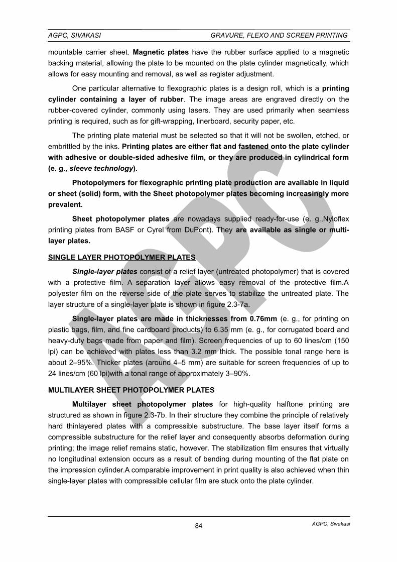
AGPC, Sivakasi
AGPC, SIVAKASI GRAVURE, FLEXO AND SCREEN PRINTING
mountable carrier sheet. Magnetic plates have the rubber surface applied to a magnetic
backing material, allowing the plate to be mounted on the plate cylinder magnetically, which
allows for easy mounting and removal, as well as register adjustment.
One particular alternative to flexographic plates is a design roll, which is a printing
cylinder containing a layer of rubber. The image areas are engraved directly on the
rubber-covered cylinder, commonly using lasers. They are used primarily when seamless
printing is required, such as for gift-wrapping, linerboard, security paper, etc.
The printing plate material must be selected so that it will not be swollen, etched, or
embrittled by the inks. Printing plates are either flat and fastened onto the plate cylinder
with adhesive or double-sided adhesive film, or they are produced in cylindrical form
(e. g., sleeve technology).
Photopolymers for flexographic printing plate production are available in liquid
or sheet (solid) form, with the Sheet photopolymer plates becoming increasingly more
prevalent.
Sheet photopolymer plates are nowadays supplied ready-for-use (e. g.,Nyloflex
printing plates from BASF or Cyrel from DuPont). They are available as single or multi-
layer plates.
SINGLE LAYER PHOTOPOLYMER PLATES
Single-layer plates consist of a relief layer (untreated photopolymer) that is covered
with a protective film. A separation layer allows easy removal of the protective film.A
polyester film on the reverse side of the plate serves to stabilize the untreated plate. The
layer structure of a single-layer plate is shown in figure 2.3-7a.
Single-layer plates are made in thicknesses from 0.76mm (e. g., for printing on
plastic bags, film, and fine cardboard products) to 6.35 mm (e. g., for corrugated board and
heavy-duty bags made from paper and film). Screen frequencies of up to 60 lines/cm (150
lpi) can be achieved with plates less than 3.2 mm thick. The possible tonal range here is
about 2–95%. Thicker plates (around 4–5 mm) are suitable for screen frequencies of up to
24 lines/cm (60 lpi)with a tonal range of approximately 3–90%.
MULTILAYER SHEET PHOTOPOLYMER PLATES
Multilayer sheet photopolymer plates for high-quality halftone printing are
structured as shown in figure 2.3-7b. In their structure they combine the principle of relatively
hard thinlayered plates with a compressible substructure. The base layer itself forms a
compressible substructure for the relief layer and consequently absorbs deformation during
printing; the image relief remains static, however. The stabilization film ensures that virtually
no longitudinal extension occurs as a result of bending during mounting of the flat plate on
the impression cylinder.A comparable improvement in print quality is also achieved when thin
single-layer plates with compressible cellular film are stuck onto the plate cylinder.
84
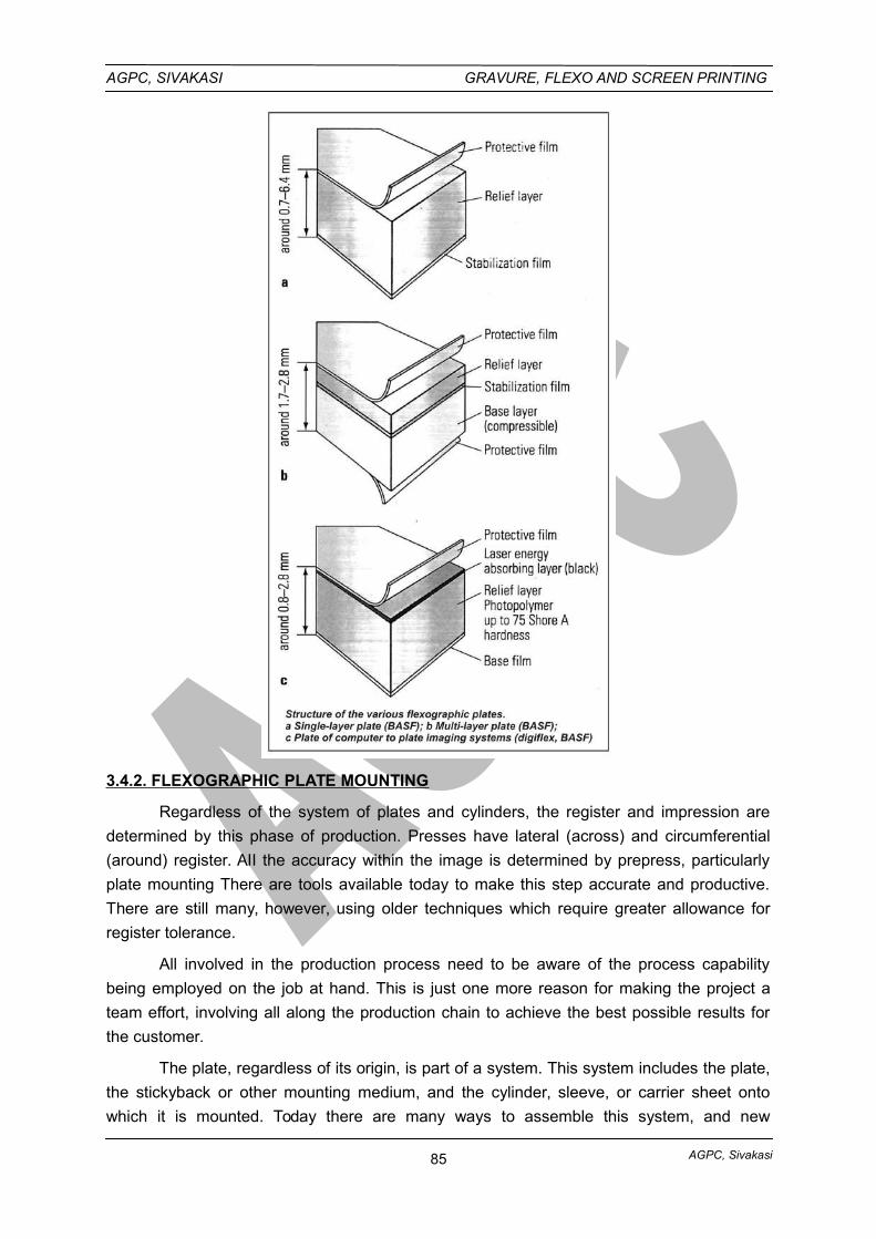
AGPC, Sivakasi
AGPC, SIVAKASI GRAVURE, FLEXO AND SCREEN PRINTING
3.4.2. FLEXOGRAPHIC PLATE MOUNTING
Regardless of the system of plates and cylinders, the register and impression are
determined by this phase of production. Presses have lateral (across) and circumferential
(around) register. AII the accuracy within the image is determined by prepress, particularly
plate mounting There are tools available today to make this step accurate and productive.
There are still many, however, using older techniques which require greater allowance for
register tolerance.
All involved in the production process need to be aware of the process capability
being employed on the job at hand. This is just one more reason for making the project a
team effort, involving all along the production chain to achieve the best possible results for
the customer.
The plate, regardless of its origin, is part of a system. This system includes the plate,
the stickyback or other mounting medium, and the cylinder, sleeve, or carrier sheet onto
which it is mounted. Today there are many ways to assemble this system, and new
85
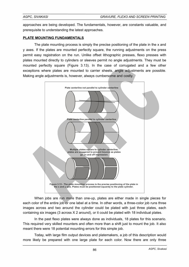
AGPC, Sivakasi
AGPC, SIVAKASI GRAVURE, FLEXO AND SCREEN PRINTING
approaches are being developed. The fundamentals, however, are constants valuable, and
prerequisite to understanding the latest approaches.
PLATE MOUNTING FUNDAMENTALS
The plate mounting process is simply the precise positioning of the plate in the x and
y axes. If the plates are mounted perfectly square, the running adjustments on the press
permit easy registration on the run. Unlike offset lithographic presses, flexo presses with
plates mounted directly to cylinders or sleeves permit no angle adjustments. They must be
mounted perfectly square (Figure 3.13). In the case of corrugated and a few other
exceptions where plates are mounted to carrier sheets, angle adjustments are possible.
Making angle adjustments is, however, always cumbersome and costly.
Plate centerline not parallel to cylinder centerline
Plate centerline parallel to cylinder centerline
Multiple plates square to cylinder centerline;plates are staggered to prevent bounce as plates
go on and off impression.
Figure 3.13 - The plate mounting process is the precise positioning of the plate inthe x and y axis. Plates must be positioned squarely to the plate cylinder.
When jobs are run more than one-up, plates are either made in single pieces foreach color of the entire job or one label at a time. In other words, a three-color job runs threeimages across and two around the cylinder could be plated with just three plates, eachcontaining six images (3 across X 2 around), or it could be plated with 18 individual plates.
In the past flexo plates were always done as individuals, 18 plates for this scenario.This required very skilled mounters and often more than a shift just to mount the job. It alsomeant there were 18 potential mounting errors for this simple job.
Today, with large film output devices and platemakers, a job of this description wouldmore likely be prepared with one large plate for each color. Now there are only three
86
AGPC, Sivakasi
AGPC, SIVAKASI GRAVURE, FLEXO AND SCREEN PRINTING
positioning tasks. There are also precision tools available to assure accurate location ofeach plate. The cost of plate mounting has moved from labor to tools and technology. Thispermits much shorter times to press and far less press downtime for repositioning plates thatwere poorly mounted.
STICKYBACK TYPE
Flexo plates mounting
Flexographic printing plates are usually secured to the printing cylinder by means oftwo-sided self-adhesive material. The plates are mounted on the plate cylinder and pre-registered in position on special equipment designed for this purpose. Several platecylinders are normally available for one machine to enable pre-mounting of plates. Thisreduces the unproductive time on the machine to a minimum. A 'cushion-back’ adhesivelayer behind the stereo is sometimes used to compensate for any inaccuracies in the plateor press. However, in halftone printing this can lead to greater enlargement of highlight dotsthan would otherwise have been the case. The current best practice is considered to be touse the thinnest possible adhesive tape since the potential for introduction of thicknessvariation is then minimized.
Two-sided self adhesive tapes are also called as stickyback. Stickyback comes inselected thicknesses, densities, and hardnesses. Some stickybacks simply adhere the plateand may be as thin as 0.002 in. Other stickybacks are thicker, most commonly 0.015 in. and0.020 in. thick. These are either rigid or cushioned.
Cushion stickyback is a foam material that aids impression uniformity. Consistentthickness of stickyback is critical to the job. Variation in stickyback is the same as variation inthe plate thickness. Much research has been done to understand the ideal stickyback andplate combinations for selected types of images. The mounting tape has a major effect onthe print quality of the product. To oversimplify, harder tape is best for solids and soft for finescreens. Since there is considerable interaction among graphics, inks, and substrates, theoptimum choice is generally given serious thought. This is an area where top printers oftenfind that one size does not fit all.
PLATE ALIGNMENT CONCEPTS
For the purpose of this text, all plate alignment systems will be grouped into three
categories: i) optical, ii) register pins, or iii) videoscopes and microtargets. These are not
clean divisions because some employ more than one concept.
i. OPTICAL DEVICES
Optical devices rely on simple visual alignment of the position marks on the plate with
grids or layout lines. The simplest optical approach relies on scribed lines in the cylinder
itself. The mounter simply lines up the vertical and horizontal center marks of the plate with
the marks scribed into the cylinder. Simple? Yes; remember, all that is required is a plate
mounted squarely on a cylinder. Other optical approaches enable the plate to be positioned
squarely on a sheet or table and then transferred to the cylinder. Figure 3.14 illustrates one
simple visual approach where the plate is aligned with a grid.
87
AGPC, Sivakasi
AGPC, SIVAKASI GRAVURE, FLEXO AND SCREEN PRINTING
Devices called optical mounter-proofers have been used for many years. Two such
mounters known by the names of their inventors, Harley and Mosstype (for Earl Harley and
Samuel Moss), employ mirrors to enable the operator to line up the marks on the plate with
a drafted position layout on the impression cylinder of the device.
The operator uses the drafting features of the machine to draw out the press/web
layout. Then the operator inserts a print cylinder for one color into the machine and attaches
a gear that in the “around the cylinder” position. If the plates are to be mounted three-
around, after each plate is positioned the cylinder is turned exactly one third the
circumference to mount the next plate. Each plate is positioned to hit exactly on the drafted
lines.
To Check register, the plates are inked and an impression made onto the drafted
sheet. After each cylinder is mounted it is inked and proofed, resulting in a paper-and-ink
proof of the entire mounted job. The proof normally is checked both in mounting and the
press department where it goes along with the cylinders for the pressrun.
Optical mounter-proofers require very skilled operators. It could take more than one
shift to mount a six-color, complex job where many plates are involved. Bieffebi is another
optical mounter-proofer based on the same principles.
Today these same “mounter-proofers” are often retrofitted with pin register systems
or videoscopes to permit more critical alignment with far less skill and time. There are
several retrofit options that permit modernizing older, yet still-valuable mounter-proofers.
Figure 3.15 shows a typical mounter-proofer.
ii. PIN REGISTRATION SYSTEMS
The graphic arts industry has employed pins to align images for decades. Prior to
sheet polymer plate materials, the use of register pins had to stop with the final film in the
flexographic process. Today there are approaches using pins to line up images with play and
plates with cylinders and carrier sheets.
Pin registration of images on film to the plate is achieved by drilling sheet
photopolymer plate material with holes matched to holes in the final films. After back-
exposing the plate material, the pins are placed through the holes and used to position the
film during face exposure, just as is routinely done with litho plates. These same registry
holes are then used for mounting onto the cylinders.
It is more common for plates to be made without regard to image position and then
drilled for plate mounting with pins. This approach involves locating the imaged plate
precisely using microscopes and tiny microtargets built into the image. Once positioned the
plate is drilled for mounting. The plate is then located on pins, sometimes right on the
cylinder or carrier. Pins are sometimes part a mounting device used to transfer the plate to
the cylinder.
88
AGPC, Sivakasi
AGPC, SIVAKASI GRAVURE, FLEXO AND SCREEN PRINTING
Figure 3.16 illustrates the concept of employing pins to position the plate for
mounting. On the top the plate is precisely aligned and drilled with holes for register pins. On
the bottom the plate is positioned on pin as it is transferred to the stickyback on the print
cylinder.
iii. VIDEO MICROSCOPES
Video microscopes represent the third approach. While these same tools are also
used in some pin register systems, this concept by-passes drilling and simply permits
precise positioning of the plate over the cylinder/carrier and attaching without any additional
action. A pair of microtargets are imaged into all the plates. The mounting system has at
least two video microscopes. If multiple plates are being mounted, there must be two scopes
for each plate position. The plate is precisely located so the video crosshair is exactly on the
microtarget. Once located, the plate is brought into contact with the stickyback. The position
of the scopes is locked for all colors being mounted and documented for future mounting, or
for remounting should a plate be damaged on press.
This is a very accurate and fast approach to mounting. It is so reliable that many
printers no longer demand a proof from the mounted plates. This approach to mounting also
has a perfect fit to modern digital prepress, which makes exact location of microtargets a
routine part of the workflow. Figure 3.17 shows a Heaford videoscope plate register system.
At the right the operator positions a plate while watching the monitor to see when it is
perfectly aligned.
TYPES OF FLEXO PLATE CYLINDERS
There are three general cylinder approaches from which flexographers may choose
when building their plate system. (See Figure 3.18.) They may be integral, demountable
(small narrow-web examples shown), or lightweight sleeves.
Integral plate cylinders are the most expensive and, arguably, probably the most
accurate and precise over their lifespan. The one-piece cylinder is made for a single repeat
length, circumference, and has precision journals to hold gears and bearings. They are often
unique to a given press. Since they are on piece, they have no tolerances for assembly and
are subjected to le labor activity, meaning less chance for accidental damage.
Demountable cylinder systems consist of a shaft or mandrel, art metal sleeves
machined to specific repeat lengths. These steel or aluminum sleeves are installed for the
specific job, and corresponding gears and bearings are installed at the time of mounting.
Therefore only one set of shafts with precision bearing and gear journals is required for a
wide variety of repeat lengths on a press. This system is the dominant approach in narrow-
web applications,
89
AGPC, Sivakasi
AGPC, SIVAKASI GRAVURE, FLEXO AND SCREEN PRINTING
Lightweight sleeves are a solution for the larger sizes of presses where the costs of
cylinders are especially high and where the demount system still requires a lifting apparatus
for handling. Jobs can be set up for mounting directly to the sleeve, or the sleeve may be
covered with vulcanized and ground rubber to provide desired resilience qualities and to
permit a range of repeat lengths from just a few mandrel diameters. Figure 3.19 illustrates
how a single sleeve and mandrel size can accommodate a range of repeat lengths.
To run light sleeves the press is equipped with hollow plate cylinder mandrels fitted
with compressed air fixtures. The sleeve is slipped over the end of the mandrel by hand. Air
is applied to the mandrel and passes through small holes positioned along the entire length
of the mandrel. This air provides sufficient pressure to expand the sleeve just enough to be
pushed by hand all the way onto the mandrel. When the air pressure is removed the sleeve
is too tight to be moved. After use the mandrel is again pressurized and the sleeve is
removed. Very large sleeves are still light enough to be handled manually, making their use
and storage easy, and requiring the least in materials handling systems.
Sleeves offer a variety of other benefits for the creative. Among the most obvious
advantages is the ability to leave jobs mounted for running on any one of a variety of
presses. Jobs can be left mounted for reruns since less cost is tied up with cylinder
inventory. This also results in substantial savings in plate mounting and in remaking plates
damaged during removal and storage. Jobs can be mixed on a pressrun by mounting more
than one narrow sleeve on a mandrel.
Where a converter runs repeat and standard items, this makes it possible to offer
short runs without unrealistic waste of press capacity. They are also popular where
continuous digitally imaged pattern rolls are used.
The sleeve allows much less expensive inventory of patterns for repeating jobs and
costs of handling and shipping to the laser engraver are substantially reduced. Sleeves are
also a convenient vehicle for trying out new plate thicknesses without investing in an
inventory of cylinders. Since they can be easily built up to various thicknesses they are
useful as tools for process improvement.
3.5. SLEEVE TECHNOLOGY, DIRECT LASER ENGRAVING
3.5.1. SLEEVE TECHNOLOGY
The principle of sleeve technology consists of a thin-walled metal sleeve, the inside
diameter of which is dimensioned so that the sleeve can be expanded under compressed air
and pushed axially onto the plate cylinder. Once the compressed air has been turned off, the
sleeve sits firmly on the plate cylinder by force fit. Before being pushed onto the plate
cylinder, the entire outer surface of this sleeve is covered with plate base material. The
cylindrical plate is directly imaged using lasers in a round imagesetter. With this process the
longitudinal extension that takes place during conventional mounting and the inaccuracies
connected with the attachment of the block do not occur.
There are two modes of procedure for sleeve technology:
90
AGPC, Sivakasi
AGPC, SIVAKASI GRAVURE, FLEXO AND SCREEN PRINTING
Covering the sleeve with a laser exposable plate cut exactly to the size of its
cylinder casing, in which case the sleeve has a seam.
The use of seamless sleeves which have been already fully prepared by the
manufacturer with the relief layer (e. g., BASF digisleeve).
3.5.2. DIRECT LASER ENGRAVING
In flexographic computer to plate systems for producing relatively soft rubber printing
plates, the recessed, ink-free parts of the printing plate are removed directly by laser energy
(laser engraving). The ablated particles are removed by suction. High-power lasers (such as
1–2.5 kW CO2 lasers) are used for this activity. The laser engraving of gummed rollers for
continuous printing has been possible since the seventies.With the maturing of computer
technology, computer to plate became available as early as the end of the eighties.
UV direct imaging is available as the “UV Laser Platesetter” from Napp Systems. By
means of high-power UV laser light the polymerisation needed for producing the flexographic
plate is carried out directly pixel by pixel.
LASER ENGRAVING ON RUBBER ROLLERS
The first direct-to-plate process was laser engraving rubber. In the process gum is
vulcanized and precisely ground to final plate thickness. It is then mounted to a drum and
rotated in front of a CO2 laser. The nonimage area is burned away leaving the image in relief
and the plate ready for mounting (see Figure 3.20). Laser-engraved rubber plates have
precisely controlled shoulder angle, and resolution as high as 120-line halftone screens can
be produced. One of the most appealing applications of this technology is the production of
continuous-pattern images. Conventional plates always leave a gap of line where the two
ends of the plate come together on the cylinder. Continuous patterns are laser-engraved
onto rubber-covered rollers. Rubber is vulcanized to roller bases and ground to the exact
repeat length. This roller is then laser-imaged. Gift wrap and wall covering often require
uninterrupted patterns, and laser imaging is a popular solution. This process also eliminates
any plate mounting and the cost of potential register flaws that go with mounting.
3.6. CORONA TREATMENT, FLEXO SUBSTRATES
SURFACE TREATMENT
Surface treating parts prior to printing ensures proper and complete ink adhesion and
can often make the printing process run more efficiently. Some materials are impossible to
print unless they have undergone surface treatment.
Materials having a low affinity for printing inks (low surface tension) can be modified
to improve their printability. There are three general ways this is done.
3.6.1. CORONA TREATMENT
The most common method today is corona discharge treatment, which raises the
printability by applying a high-voltage, high-frequency electrical charge to the web.
Treatment levels fall off with time. Materials treated by the manufacturer for printability may
91
AGPC, Sivakasi
AGPC, SIVAKASI GRAVURE, FLEXO AND SCREEN PRINTING
eventually lose their treatment level to the point that they must be retreated before
successful printing.
Wide-web printers of plastic bags and film laminates often have corona treaters on
the infeed sections of their presses, allowing them to raise the dyne level immediately prior
to printing. These treaters not only increase the surface area, but also burn away slip agents
and dust, which further improves ink transfer and adhesion.
Surface treatment is frequently used in printing and other converting processes to
alter the surface characteristics of a material. Treatment processes may be designed to
improve a substrate’s wetting properties, which influence how well inks and coatings will flow
out over the material’s surface. Treatments may also be used to enhance the bonding
between the substrate and the applied material or eliminate static charges that have
accumulated on the substrate surface. Surface-treatment technologies play a key role in
preparing the surfaces of many commonly used packaging materials (paper, plastic, foil,
etc.) for subsequent processing steps.
Most inks, paints, coatings, and adhesives resist wetting on the surface of virgin-
plastic parts, which are newly thermoformed or molded items characterized by an inert, non-
porous, low-energy surface. Virgin-plastic parts that screen and pad printers typically work
with include items made from polyethylene, polypropylene, and other polyolefin’s. These
materials tend to be very slippery and feel greasy to the touch.
Another common method is flame treatment, whereby the web passes over gas
burners which serve to clean and modify the surface resulting in improved printability.
The third approach is to apply a printable coating. This is most commonly done by
the packagers of specialty pressure-sensitive laminates. The narrow web label manufacturer
is called on to print a wide variety of specialty surfaces. The supplier to the narrow-web
printer is a converter who buys these materials in large rolls, slits to the narrow-web sizes,
applies adhesives to the back, and rewinds with a removable liner. This is the Simple
structure of a pressure-sensitive label stock. These repackagers commonly apply printable
clear coatings so the narrow-web printer can use his normal ink system.
Since there is a variety of materials and presses, the use of an in-line treater is often
not practical or affordable. Narrow-web printers who specialize in certain nonporous
substrate applications do treat or coat in-line to save on costs of special treating and
packaging.
3.6.2. Flexo Substrates
Introduction
The materials on which we print are many and varied, due to the virtues and the
versatility of the flexographic printing process. There is indeed almost no material which has
not been or cannot be printed by it.
The kinds of materials on which we print are divided into several major groups as
follows:
92
AGPC, Sivakasi
AGPC, SIVAKASI GRAVURE, FLEXO AND SCREEN PRINTING
1. Paper and paperboard stocks
2. Corrugated stocks
3. Films
4. Foils
5. Laminates
1. PAPER AND PAPERBOARD STOCKS
Paper is made in many different weights and thickness and in a wide variety ofdensities and surface finishes. Thick papers are usually referred to as “paperboard”. There isno definite point where paper becomes paperboard. The terminology usually depends onsuch factors as density, composition, end use.
“Basis weight” is the term used to define the weight of various grades of paper,referring to the weight of a ream of that grade.
Glassine
Glassine is paper made by prolonged “beating” or “hydrating” pulp, generallysulphite, down to a jelly-like consistency. The resulting sheet is very dense, and would behard and brittle without the addition of softeners and plasticizers which act as lubricants tomake the sheet more pliable.
Parchment Paper
Parchment papers are made by briefly immersing a web of unsized paper in a bath ofsulphuric acid, then quickly washing out the acid.
Release-Coated Papers
Paper coatings with resin, lacquer or latex type binders are usually receptive to flexoinks, in fact, many enhance printability, although some coatings tend to decrease theabsorbency of the paper surface so that ink trapping and drying problems are increased.
Paper Coating Material
Polyethylene is increasingly used as a paper coating material. If the polyethylenesurface is to be printed, the same principles apply as in printing polyethylene films exceptthat the paper adds dimensional stability and tensile strength. Polyethylene surfaces must betreated for a ink adhesion, and should be checked for such treatment prior to beginning thejob.
2. CORRUGATED STOCKS
The printing surface of corrugated board has been almost exclusively of natural Kraftpaper. Most of the basic recommendations for printing uncoated papers stockflexographically will therefore apply to the printing of corrugated board. There is also agrowing demand for boxes whose printing characteristics have been altered by the use ofvarious impregnating and/or coating materials to improve water resistance. These boxes areused to ship iced poultry, fish and these boxes are presently produced by several costly andseparate operations.
93
AGPC, Sivakasi
AGPC, SIVAKASI GRAVURE, FLEXO AND SCREEN PRINTING
3. FILMS
The following are types of films:
1. CELLOPHANES (plain and coated)
2. CELLULOSE ACETATE FILMS
3. ETHYL CELLULOSE
4. FLUOROHALOCARBON FILMS
5. METHYL CELLULOSE
6. POLYSTERS
7. POLYETHYLENE
8. POLYPROPYLENE
9. POLYSTYRENE
10. RUBBER HYDROCHLORIDE
11. VINYL CHLORIDE CO-POLYMERS
12. VINYLIDENE CHLORIDE
13. CO-POLYMERS
CELLOPHANES:
Cellophane is a clear, transparent, flexible, odourless, grease-proof, non-toxic,
regenerated cellulose film widely used for packaging an endless variety of consumer
products, and for miscellaneous other uses. Cellophane like paper is made from cellulose, of
which the main source is wood. Cellophane is made by processing highly purified wood pulp
into a transparent solution.
CELLULOSE ACETATE FILMS:
The group covered under the classification “acetate films” includes cellulose acetate,
cellulose tri-acetate, and cellulose acetate butyrate. These are clear, transparent, odourless,
tasteless, dimensionally stable films compounded from plasticized to the printer in
thicknesses from 0.0005" to about 0.10".
Cellulose acetate films are relatively water proof, but are not at all moisture vapor
proof.
ETHYL CELLULOSE:
Ethyl cellulose is a clear, transparent, flexible, odourless, tasteless, water-insoluble,
heat-sealable film. The film may be produced in such a variety of modifications that it is
difficult to give anything but a general description. Like the acetate films, only a small volume
of ethyl cellulose film is printed.
FLUOROHALOCARBON FILMS:
This family of films, known by such trade names as ACLAR (Allied Chemical) and
TEFLON (Dupont) are remarkably strong, chemically inert, flexible, thermoplastic, and
possess several unusual properties of interest in some areas of the flexible packaging field.
94
AGPC, Sivakasi
AGPC, SIVAKASI GRAVURE, FLEXO AND SCREEN PRINTING
Significant properties of these films include excellent clarity, zero water absorption,
high tensile strength, non-flammability, high softening temperature, and very high chemical
resistance, including little or no effect from most common acids, alkalis, solvents, oxygen, or
ultra-violet exposure.
METHYL CELLULOSE:
Methyl cellulose is a methyl ester of cellulose, in film form, which is clear,
transparent, odorless, tasteless, flexible, and water soluble. The latter characteristic would
make its use advantageous in packaging “throw-in” packs of soaps, bactericides, etc., but
very little of this type of film is printed.
POLYYESTER FILMS:
Polyester films are available in calipers ranging from a quarter of a thousandth of an
inch (.00025") in thickness to as much as seven to ten thousandths.
1. As “metallic yarn” when vacuum metalized, laminated and slit into narrowwidths.
2. As a tough surface laminate for paper paperboard, and foil, either clearor metalized, smooth or embossed,
3. Scuff panels on automobile doors.
4. Replacement for chrome decorative of functional panels.
5. Base for recording tapes.
6. As a tough, durable surface, or as a window in display packagesrequiring greater strength than available in other films.
7. Alone or laminated to other material for decorative paneling, shoes,pocket hooks, belts, lamp shades, etc.
8. For “boil-in” food pouches, permitting foods to be cooked in the package.
9. Vacuum packaging.
POLYETHYLENE:
Polyethylene is a thermoplastic, or heat softening resin formed by the polymerization
of ethylene gas under high pressure and temperature. The polyethylene film or tubing
extruded from this resin is relatively clear, transparent, odorless, tasteless, non-toxic, water
and moisture-vapor proof, heat-sealable, elastic, durable and extremely flexible even at sub
freezing temperatures.
Polyethylene resin, extruded into film form, is not printable until its surface is “treated”
so that ink will adhere to it. Treatment adversely affects heat-sealability of polyethylene
surfaces in proportion to the degree of treatment. Treatment can decrease tear and impact
resistance of the film.
Polyethylene film is usually treated for printing in connection with the extruding
operation by either of two methods. One of these methods called “flame-treatment” applies a
95
AGPC, Sivakasi
AGPC, SIVAKASI GRAVURE, FLEXO AND SCREEN PRINTING
carefully controlled gas flame to the surface of the film while the film is passing around as
refrigerated roller to prevent it from softening due to the heat of the flame.
Polyethylene film to be printed varies between .0005" and 0.10" in thickness, with the
most popular thickness range between 0.001" and .0015".
POLYPROPYLENE:
Polypropylene is so similar in apparent physical characteristics to some of the higher
density polyethylene films that it is difficult to distinguish between them. However,
polypropylene is superior to corresponding density polyethylene in grease resistance, gas
transmission rate, impact, and tear resistance.
POLYSTYRENE:
Polystyrene is a clear, transparent, odorless resin formed by carefully controlled
polymerization of highly purified styrene, sometimes known as vinyl benzene. As a film it is
unplasticized, semi-rigid, semi-flexible, weak in strength, brittle, is easily attacked by ink
solvents, and has poor heat sealing characteristics. Although it is a low cost material, it is
rarely used as a film, a notable exception being the packaging of fresh tomatoes.
4. ALUMINIUM FOILS:
Aluminium foils are thin, continuous sheets or webs of metallic aluminium or
aluminium alloys which may be flexible, semi-rigid, depending upon their thickness and
temper or hardness. They may be unmounted metal or the metal foil may be supported by
various films, paper, or paperboard, using adhesives, waxes, or plastics for bonding. Most
aluminium foil used in the flexo printing and packaging industries ranges from .0002" in
thickness to as much as .005" or .006".
Aluminium foil is made by hot or cold rolling aluminium goes in between hardened,
polished steel rollers into progressively thinner gauges until the desired thickness is
achieved.
Pure elemental aluminium and aluminium alloys are both used in making foils for
packaging, depending mainly upon the desired properties, but practically all foils contain at
least 97 percent pure aluminium.
The properties of aluminium foils are substantially those of the pure metal itself. It is
non-absorbent, odor-free, non-toxic, completely opaque, and impervious to most solvents,
oils, fats, waxes, foods and gases.
Aluminium foils are used in a wide range of familiar applications ranging from
insulation through military packaging to gift wraps, household use, a wide variety of food
packages and cigarette, ice cream, candy wrappers and the heavier gauge, more or less
rigid “cook-in/severe-in” food containers. Foils which have been adhesive-mounted or wax-
mounted to various papers and similar stocks are widely used for bags, packages, wrappers,
cans and other containers, while the most complex laminated structures made with foil,
96
AGPC, Sivakasi
AGPC, SIVAKASI GRAVURE, FLEXO AND SCREEN PRINTING
papers, films, and plastics are finding increasing uses in pouches and assorted packages for
all kinds of foods, drugs, and chemicals.
5. LAMINATES:
Laminates, rather than a single substrate, are used where product or end use
requirements are such that they cannot be met by a single material. Further, these same
stringent conditions may require a different ink than would normally be used for the surface
of the laminated structure alone.
Since laminated materials are obviously more expensive than any of their single
plies, waste is a much more important factor than in printing single webs. It is, therefore,
important to keep waste to a minimum.
97
AGPC, Sivakasi
AGPC, SIVAKASI GRAVURE, FLEXO AND SCREEN PRINTING
UNIT: III – FLEXOGRAPHY PRINTING
PART - A - 2 Marks Questions
1. Name the different flexo inking systems.
i. Two-roll ink metering systems
ii. Modified two-roll with a doctor blade ink metering system
iii. Reverse angle doctor blade ink metering system
iv. Chambered doctor blade ink metering system
2. Name the anilox cell shapes used in flexo printing.
i. Inverted pyramid shape cells
ii. Quadrangular shape cells
iii. Trihelical shape cells
3. What are the various anilox rolls available based on roller surface?
i. Laser engraved ceramic anilox rolls
ii. Conventional or Mechanical engraved chrome anilox rolls
4. Name the different layers of sheet photopolymer plates.
i. Stable base or substrate layer
ii. Light sensitive photopolymer layer
iii. Removable cover sheet layer
5. State the purpose of Corona treatment.
Corona treatment is done to eliminate static charges that have accumulated on the
substrate surface. This treatment raises the printability by applying a high-voltage, high-
frequency electrical charge to the web.
6. What is a sleeve?
Tubular component that can be mounted on a mandrel, sleeve cylinder is an
alternative to an integral or one piece cylinder.
7. Name the various Flexo plate alignment systems.
i. Optical plate alignment systems
ii. Register pins plate alignment systems
iii. Videoscopes and Microtargets plate alignment systems.
8. Define Cell depth of flexo anilox roller.
Cell depth is the next specification and is just as important as cell count. These two
specifications determine cell volume, which is the determiner of density in a given
application. When specifying an anilox roll determine the cell count and volume to do the job
and leave the depth to the anilox supplier.
9. Name the various technologies available for mounting flexo plates.
i. Plate mounting using optical devices.ii. Plate mounting using pin registration systemsiii. Plate mounting using video microscopes and microtargets.
98
AGPC, Sivakasi
AGPC, SIVAKASI GRAVURE, FLEXO AND SCREEN PRINTING
10. Name the different types of substrates used for Flexographic printing.
The kinds of materials on which we print are divided into several major groups as
follows:
1. Paper and paperboard stocks2. Corrugated stocks3. Films4. Foils5. Laminates
PART - B - 3 Marks Questions
1. What are the various anilox roll cleaning systems?
i. Jet wash type Systemii. Powder blasting systemiii. Polymer bead blasting systemiv. Dry ice systemv. Laser cleaning system
vi. Ultrasonicsvii. Alpha sound
2. What are the advantages of direct laser engraving of flexo plates?
Laser-engraved rubber plates have precisely controlled shoulder angle, andresolution as high as 120-line halftone screens can be produced. One of the most appealingapplications of this technology is the production of continuous-pattern images. Conventionalplates always leave a gap of line where the two ends of the plate come together on thecylinder. Continuous patterns are laser-engraved onto rubber-covered rollers. Gift wrap andwall covering often require uninterrupted patterns, and laser imaging is a popular solution.This process also eliminates any plate mounting and the cost of potential register flaws thatgo with mounting.
3. Draw the structure of multiplayer sheet photopolymer plates.
Multilayer sheet photopolymer plates for high-quality halftone printing arestructured as shown in figure 2.3-7b. In their structure they combine the principle of relativelyhard thinlayered plates with a compressible substructure. The base layer itself forms acompressible substructure for the relief layer and consequently absorbs deformation duringprinting; the image relief remains static, however. The stabilization film ensures that virtuallyno longitudinal extension occurs as a result of bending during mounting of the flat plate onthe impression cylinder.A comparable improvement in print quality is also achieved when thinsingle-layer plates with compressible cellular film are stuck onto the plate cylinder.
4. State the different modes of procedure for flexo sleeve technology.
There are two modes of procedure for sleeve technology:
Covering the sleeve with a laser exposable plate cut exactly to the size of its
cylinder casing, in which case the sleeve has a seam. The use of seamless sleeves which have been already fully prepared by the
manufacturer with the relief layer (e. g., BASF digisleeve).
99
AGPC, Sivakasi
AGPC, SIVAKASI GRAVURE, FLEXO AND SCREEN PRINTING
5. Define Cell count of flexo anilox roller.
Cell count refers to the number of rows of cells per linear inch. A cell count of 180
would be very coarse, found only in coating or low-end imaging applications. A cell count of
360, once considered fine, is now a middle-of-the-road roll used in good work. Today cell
counts of 700 and above are commonly used for very high-quality imaging on smooth, high-
holdout (not absorbent) substrates.
6. Define Cell volume of flexo anilox roller.
Cell volume is the key to coverage and uniformity of solids. More volume results in
more ink and, thus, better coverage. However, too much volume of ink also results in dirty
print. High-resolution images require high-line, low-volume anilox rolls. It is common to
demand at least 3½ to 4½ times more cells on-the anilox than the lines per inch in the
halftone.
PART - C: 10 Marks Questions
1. Explain the different types of flexographic inking systems with necessary diagrams.
2. Describe the various types of anilox roll cells with suitable sketches. Write about the
anilox roll cleaning systems.
3. Explain the various considerations to be made while selecting suitable anilox rollers.
4. Describe the structure of flexographic plates with necessary sketches.
5. Explain the various Flexographic plate mounting techniques.
6. Describe the direct laser engraving of flexo plates. Write about the principles of
sleeve technology.
7. Explain the various substrates used for flexo printing.
8. Describe the Corona treatment process.
9. Write short notes on (i) Anilox roller (ii) Sleeve Technology (iii) Flexo substrates.
GLOSSARY
Anilox Roll
An engraved ink-metering roll used in flexo presses to provide a controlled film of inkto the printing plates that print the substrate. The ink film is affected by the number of cellsper linear inch and volume of the individual cells in the engraving.
BCM
The abbreviation for one billion cubic microns per square inch, which is themeasurement of the volume of ink in an average engraved anilox cell.
Cell Count
The number of cells per linear inch (or centimeter) in either a laser or mechanicallyengraved anilox roll.
100
AGPC, Sivakasi
AGPC, SIVAKASI GRAVURE, FLEXO AND SCREEN PRINTING
Cell Volume
The volume delivery capability of a single anilox cell or group of cells in a given area.
Cellophane
A transparent, flexible sheeting consisting of regenerated cellulose plus plasticizers,with or without functional coatings, such as moistureproof, etc. Cellophane gainedwidespread use in the early 1930s and is credited with helping the flexo printing process toflourish.
Corona Treatment
To improve a film surface’s ink wettability, the dyne level or surface tension isincreased by applying a concentrated electrical discharge.
Doctor Roll
The fountain roll in a flexographic press which wipes against the anilox roll to removeexcess ink.
Extrusion
Continuous sheet or film (or other shapes not connected with flexography) producedby forcing thermoplastic material through a die or orifice.
Gear Marks
A defect in flexographic printing appearing as uniformly spaced, lateral variations intone corresponding exactly to the distance between the gear teeth.
Glassine
A type of translucent, flexible paper that is highly dense and resistant to the passageof oil, grease and air. Common uses are for envelopes, candy wrappers, liners for cereal andcookie boxes.
Laminate
1. A product made by bonding together two or more layers of material or materials;
2. To unite layers of materials with adhesives.
Mounting and Proofing Machine
A device for accurately positioning plates to the plate cylinder and for obtainingproofs for register and impression, off the press.
Two-roll System
The inking system commonly employed in flexographic presses, consisting of afountain roll running in an ink pan and contacting the engraved anilox roll; the two as a unit,meter the ink being transferred to the printing plates.
101
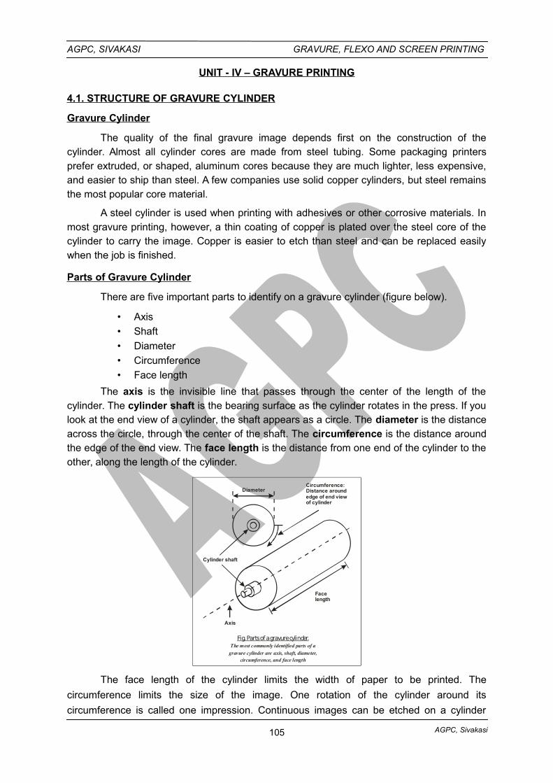
AGPC, Sivakasi
AGPC, SIVAKASI GRAVURE, FLEXO AND SCREEN PRINTING
UNIT - IV – GRAVURE PRINTING
4.1. STRUCTURE OF GRAVURE CYLINDER
Gravure Cylinder
The quality of the final gravure image depends first on the construction of thecylinder. Almost all cylinder cores are made from steel tubing. Some packaging printersprefer extruded, or shaped, aluminum cores because they are much lighter, less expensive,and easier to ship than steel. A few companies use solid copper cylinders, but steel remainsthe most popular core material.
A steel cylinder is used when printing with adhesives or other corrosive materials. Inmost gravure printing, however, a thin coating of copper is plated over the steel core of thecylinder to carry the image. Copper is easier to etch than steel and can be replaced easilywhen the job is finished.
Parts of Gravure Cylinder
There are five important parts to identify on a gravure cylinder (figure below).
• Axis
• Shaft
• Diameter
• Circumference
• Face length
The axis is the invisible line that passes through the center of the length of thecylinder. The cylinder shaft is the bearing surface as the cylinder rotates in the press. If youlook at the end view of a cylinder, the shaft appears as a circle. The diameter is the distanceacross the circle, through the center of the shaft. The circumference is the distance aroundthe edge of the end view. The face length is the distance from one end of the cylinder to theother, along the length of the cylinder.
DiameterCircumference:Distance aroundedge of end viewof cylinder
Facelength
Axis
Cylinder shaft
Fig. Parts of a gravure cylinder.The most commonly identified parts of a
gravure cylinder are axis, shaft, diameter,circumference, and face length
The face length of the cylinder limits the width of paper to be printed. The
circumference limits the size of the image. One rotation of the cylinder around its
circumference is called one impression. Continuous images can be etched on a cylinder
105
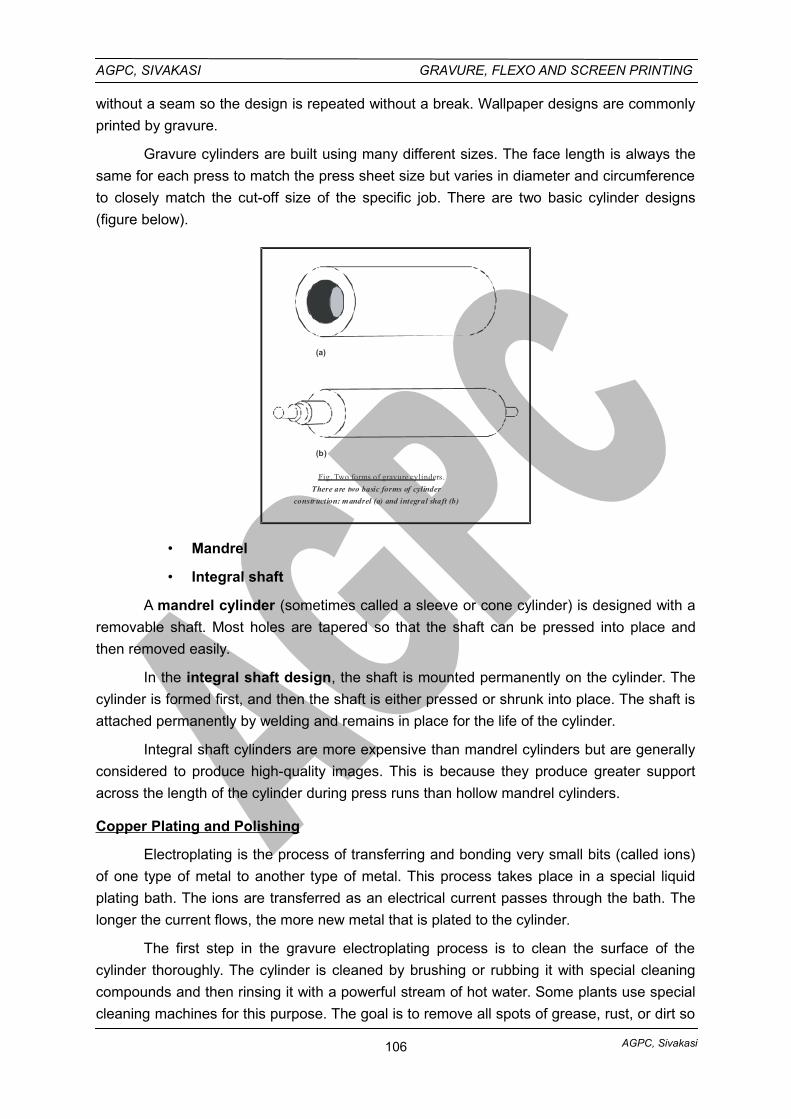
AGPC, Sivakasi
AGPC, SIVAKASI GRAVURE, FLEXO AND SCREEN PRINTING
without a seam so the design is repeated without a break. Wallpaper designs are commonly
printed by gravure.
Gravure cylinders are built using many different sizes. The face length is always the
same for each press to match the press sheet size but varies in diameter and circumference
to closely match the cut-off size of the specific job. There are two basic cylinder designs
(figure below).
(a)
(b)
Fig. Two forms of gravure cylinders.
There are two basic forms of cylinder
construction: mandrel (a) and integral shaft (b)
• Mandrel
• Integral shaft
A mandrel cylinder (sometimes called a sleeve or cone cylinder) is designed with a
removable shaft. Most holes are tapered so that the shaft can be pressed into place and
then removed easily.
In the integral shaft design, the shaft is mounted permanently on the cylinder. The
cylinder is formed first, and then the shaft is either pressed or shrunk into place. The shaft is
attached permanently by welding and remains in place for the life of the cylinder.
Integral shaft cylinders are more expensive than mandrel cylinders but are generally
considered to produce high-quality images. This is because they produce greater support
across the length of the cylinder during press runs than hollow mandrel cylinders.
Copper Plating and Polishing
Electroplating is the process of transferring and bonding very small bits (called ions)
of one type of metal to another type of metal. This process takes place in a special liquid
plating bath. The ions are transferred as an electrical current passes through the bath. The
longer the current flows, the more new metal that is plated to the cylinder.
The first step in the gravure electroplating process is to clean the surface of the
cylinder thoroughly. The cylinder is cleaned by brushing or rubbing it with special cleaning
compounds and then rinsing it with a powerful stream of hot water. Some plants use special
cleaning machines for this purpose. The goal is to remove all spots of grease, rust, or dirt so
106
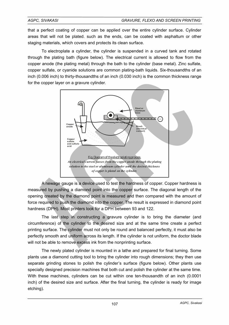
AGPC, Sivakasi
AGPC, SIVAKASI GRAVURE, FLEXO AND SCREEN PRINTING
that a perfect coating of copper can be applied over the entire cylinder surface. Cylinder
areas that will not be plated. such as the ends, can be coated with asphaltum or other
staging materials, which covers and protects its clean surface.
To electroplate a cylinder, the cylinder is suspended in a curved tank and rotated
through the plating bath (figure below). The electrical current is allowed to flow from the
copper anode (the plating metal) through the bath to the cylinder (base metal). Zinc sulfate,
copper sulfate, or cyanide solutions are common plating-bath liquids. Six-thousandths of an
inch (0.006 inch) to thirty-thousandths of an inch (0.030 inch) is the common thickness range
for the copper layer on a gravure cylinder.
Steel oraluminumbase
Brush(electricalcontact)
Coppersulfateand sulfuricacid
Copperanode
Fig. Diagram of the electroplating process.An electrical current passes from the copper anode through the plating
solution to the steel or aluminum cylinder until the desired thickness
of copper is plated on the cylinder.
A newage gauge is a device used to test the hardness of copper. Copper hardness is
measured by pushing a diamond point into the copper surface. The diagonal length of the
opening created by the diamond point is measured and then compared with the amount of
force required to push the diamond into the copper. The result is expressed in diamond point
hardness (DPH). Most printers look for a DPH between 93 and 122.
The last step in constructing a gravure cylinder is to bring the diameter (and
circumference) of the cylinder to the desired size and at the same time create a perfect
printing surface. The cylinder must not only be round and balanced perfectly, it must also be
perfectly smooth and uniform across its length. If the cylinder is not uniform, the doctor blade
will not be able to remove excess ink from the nonprinting surface.
The newly plated cylinder is mounted in a lathe and prepared for final turning. Some
plants use a diamond cutting tool to bring the cylinder into rough dimensions; they then use
separate grinding stones to polish the cylinder’s surface (figure below). Other plants use
specially designed precision machines that both cut and polish the cylinder at the same time.
With these machines, cylinders can be cut within one ten-thousandth of an inch (0.0001
inch) of the desired size and surface. After the final turning, the cylinder is ready for image
etching).
107
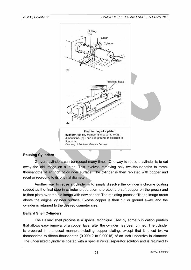
AGPC, Sivakasi
AGPC, SIVAKASI GRAVURE, FLEXO AND SCREEN PRINTING
Reusing Cylinders
Gravure cylinders can be reused many times. One way to reuse a cylinder is to cut
away the old image on a lathe. This involves removing only two-thousandths to three-
thousandths of an inch of cylinder surface. The cylinder is then replated with copper and
recut or reground to its original diameter.
Another way to reuse a cylinder is to simply dissolve the cylinder’s chrome coating
(added as the final step in cylinder preparation to protect the soft copper on the press) and
to then plate over the old image with new copper. The replating process fills the image areas
above the original cylinder surface. Excess copper is then cut or ground away, and the
cylinder is returned to the desired diameter size.
Ballard Shell Cylinders
The Ballard shell process is a special technique used by some publication printers
that allows easy removal of a copper layer after the cylinder has been printed. The cylinder
is prepared in the usual manner, including copper plating, except that it is cut twelve
thousandths to fifteen-thousandths (0.00012 to 0.00015) of an inch undersize in diameter.
The undersized cylinder is coated with a special nickel separator solution and is returned to
108
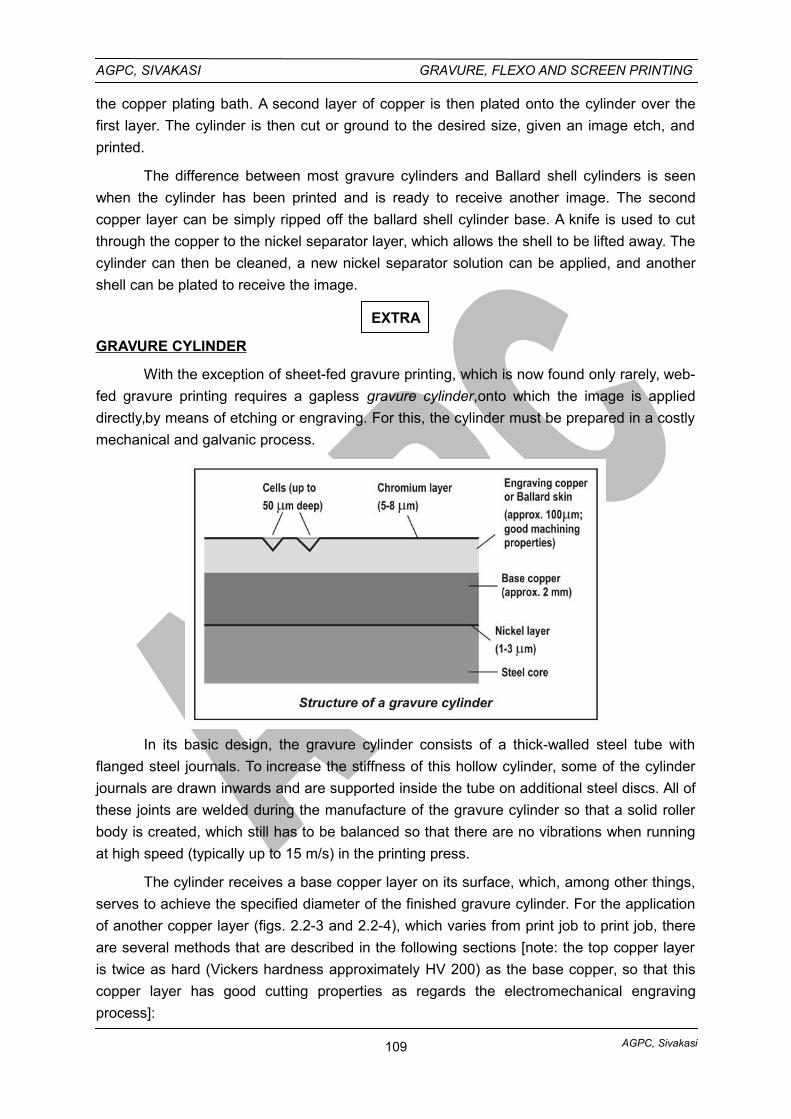
AGPC, Sivakasi
AGPC, SIVAKASI GRAVURE, FLEXO AND SCREEN PRINTING
the copper plating bath. A second layer of copper is then plated onto the cylinder over the
first layer. The cylinder is then cut or ground to the desired size, given an image etch, and
printed.
The difference between most gravure cylinders and Ballard shell cylinders is seen
when the cylinder has been printed and is ready to receive another image. The second
copper layer can be simply ripped off the ballard shell cylinder base. A knife is used to cut
through the copper to the nickel separator layer, which allows the shell to be lifted away. The
cylinder can then be cleaned, a new nickel separator solution can be applied, and another
shell can be plated to receive the image.
EXTRA
GRAVURE CYLINDER
With the exception of sheet-fed gravure printing, which is now found only rarely, web-
fed gravure printing requires a gapless gravure cylinder,onto which the image is applied
directly,by means of etching or engraving. For this, the cylinder must be prepared in a costly
mechanical and galvanic process.
In its basic design, the gravure cylinder consists of a thick-walled steel tube with
flanged steel journals. To increase the stiffness of this hollow cylinder, some of the cylinder
journals are drawn inwards and are supported inside the tube on additional steel discs. All of
these joints are welded during the manufacture of the gravure cylinder so that a solid roller
body is created, which still has to be balanced so that there are no vibrations when running
at high speed (typically up to 15 m/s) in the printing press.
The cylinder receives a base copper layer on its surface, which, among other things,
serves to achieve the specified diameter of the finished gravure cylinder. For the application
of another copper layer (figs. 2.2-3 and 2.2-4), which varies from print job to print job, there
are several methods that are described in the following sections [note: the top copper layer
is twice as hard (Vickers hardness approximately HV 200) as the base copper, so that this
copper layer has good cutting properties as regards the electromechanical engraving
process]:
109
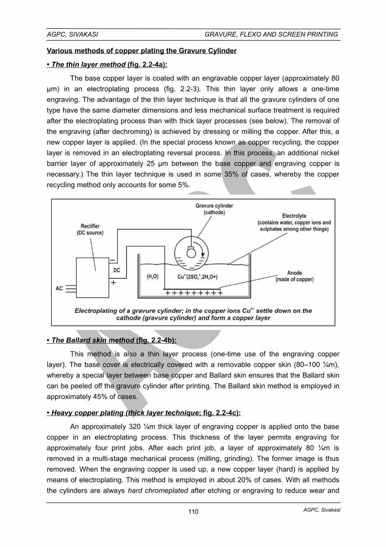
AGPC, Sivakasi
AGPC, SIVAKASI GRAVURE, FLEXO AND SCREEN PRINTING
Various methods of copper plating the Gravure Cylinder
• The thin layer method (fig. 2.2-4a):
The base copper layer is coated with an engravable copper layer (approximately 80
µm) in an electroplating process (fig. 2.2-3). This thin layer only allows a one-time
engraving. The advantage of the thin layer technique is that all the gravure cylinders of one
type have the same diameter dimensions and less mechanical surface treatment is required
after the electroplating process than with thick layer processes (see below). The removal of
the engraving (after dechroming) is achieved by dressing or milling the copper. After this, a
new copper layer is applied. (In the special process known as copper recycling, the copper
layer is removed in an electroplating reversal process. In this process, an additional nickel
barrier layer of approximately 25 µm between the base copper and engraving copper is
necessary.) The thin layer technique is used in some 35% of cases, whereby the copper
recycling method only accounts for some 5%.
• The Ballard skin method (fig. 2.2-4b):
This method is also a thin layer process (one-time use of the engraving copper
layer). The base cover is electrically covered with a removable copper skin (80–100 ¼m),
whereby a special layer between base copper and Ballard skin ensures that the Ballard skin
can be peeled off the gravure cylinder after printing. The Ballard skin method is employed in
approximately 45% of cases.
• Heavy copper plating (thick layer technique ; fig. 2.2-4c):
An approximately 320 ¼m thick layer of engraving copper is applied onto the base
copper in an electroplating process. This thickness of the layer permits engraving for
approximately four print jobs. After each print job, a layer of approximately 80 ¼m is
removed in a multi-stage mechanical process (milling, grinding). The former image is thus
removed. When the engraving copper is used up, a new copper layer (hard) is applied by
means of electroplating. This method is employed in about 20% of cases. With all methods
the cylinders are always hard chromeplated after etching or engraving to reduce wear and
110
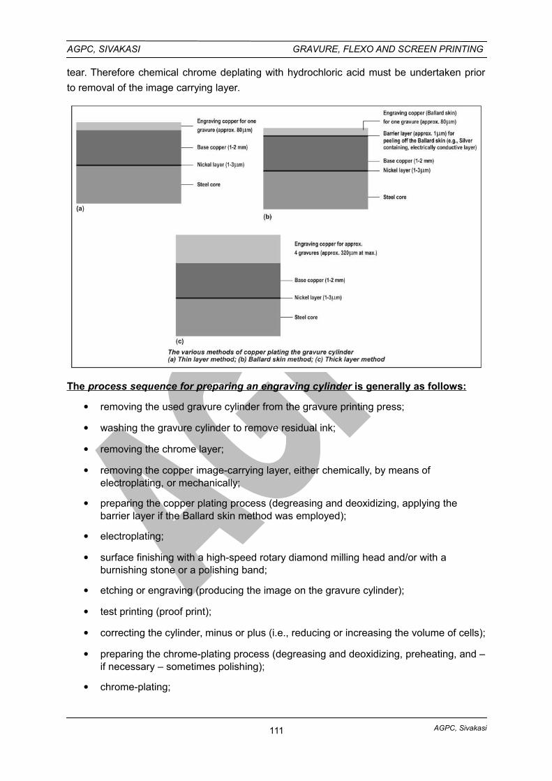
AGPC, Sivakasi
AGPC, SIVAKASI GRAVURE, FLEXO AND SCREEN PRINTING
tear. Therefore chemical chrome deplating with hydrochloric acid must be undertaken prior
to removal of the image carrying layer.
The process sequence for preparing an engraving cylinder is generally as follows:
removing the used gravure cylinder from the gravure printing press;
washing the gravure cylinder to remove residual ink;
removing the chrome layer;
removing the copper image-carrying layer, either chemically, by means of electroplating, or mechanically;
preparing the copper plating process (degreasing and deoxidizing, applying the barrier layer if the Ballard skin method was employed);
electroplating;
surface finishing with a high-speed rotary diamond milling head and/or with a burnishing stone or a polishing band;
etching or engraving (producing the image on the gravure cylinder);
test printing (proof print);
correcting the cylinder, minus or plus (i.e., reducing or increasing the volume of cells);
preparing the chrome-plating process (degreasing and deoxidizing, preheating, and –if necessary – sometimes polishing);
chrome-plating;
111
AGPC, Sivakasi
AGPC, SIVAKASI GRAVURE, FLEXO AND SCREEN PRINTING
surface-finishing with a fine burnishing stone or abrasive paper;
storing the finished cylinder or installing it directly in the gravure printing press.
Today, all these operations are performed, more or less fully automated, in
production lines, whereby overhead traveling cranes and in some cases the transportation of
the gravure cylinder from station to station is carried out by automated guided vehicle (AGV)
systems.
4.2.1. GRAVURE DRYING SYSTEM
The ink used for gravure printing has a low viscosity, so that the ink in the cells can
run out properly and be transferred onto the paper. This low viscosity is principally achieved
by using a high proportion of solvent with low boiling point in the ink. To dry the printed ink,
the solvent must evaporate in a high velocity air dryer after leaving the printing nip.
Previous systemss, such as counter flow/parallel flow drying systems and heating
drums are no longer used. Today, high-velocity nozzle dryers are used. Radial fans route the
air in pipes fitted closely above the web and equipped with circular or slot nozzles. The air
hits the web vertically, and thus the fresh print. The effect of the impact turns the air around
by 180° and returns between the pipes back to the radial fans to be fed back to the nozzle
pipes. In front of the radial fans, a part of this circulated air is branched off and routed into a
solvent recovery unit in order to prevent the concentration of solvents in the ambient air from
rising strongly. This proportion of air is automatically replaced by fresh air or ventilation air.
In many cases, the modern high-velocity nozzle dryers can operate without the need
for heating the air – air at room temperature is sufficient for the slightly volatile Toluene
(solvent) to evaporate from the ink; the air is slightly heated due solely to its friction by
circulation. If an additional heating unit is required, this is installed behind the exhaust of the
radial fan.
Since not only the speed at which the air emerges from the nozzles, but also the
length of the dryer plays a decisive role in determining the effectiveness of drying and
therefore the maximum production speed (typically 15 m/s) of the gravure printing press, the
dryers are placed on both sides and surround the entire printing unit. Therefore, the term
“drying hoods” is often used. Depending on the type of solvent used, shorter drying units,
which do not surround the entire printing unit, are sufficient (fig. below).
112
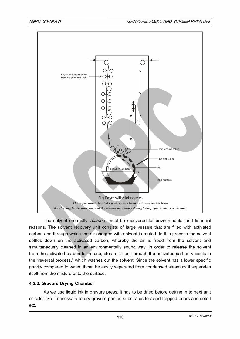
AGPC, Sivakasi
AGPC, SIVAKASI GRAVURE, FLEXO AND SCREEN PRINTING
Ink Fountain
Ink
Doctor Blade
Impression roller
Gravure Cylinder
Dryer (slot nozzles onboth sides of the web)
Fig. Dryer with slot nozzlesThe paper web is blasted wit air on the front and reverse side from
the slot nozzles because some of the solvent penetrates through the paper to the reverse side.
The solvent (normally Toluene) must be recovered for environmental and financial
reasons. The solvent recovery unit consists of large vessels that are filled with activated
carbon and through which the air charged with solvent is routed. In this process the solvent
settles down on the activated carbon, whereby the air is freed from the solvent and
simultaneously cleaned in an environmentally sound way. In order to release the solvent
from the activated carbon for re-use, steam is sent through the activated carbon vessels in
the “reversal process,” which washes out the solvent. Since the solvent has a lower specific
gravity compared to water, it can be easily separated from condensed steam,as it separates
itself from the mixture onto the surface.
4.2.2. Gravure Drying Chamber
As we use liquid ink in gravure press, it has to be dried before getting in to next unit
or color. So it necessary to dry gravure printed substrates to avoid trapped odors and setoff
etc.
113
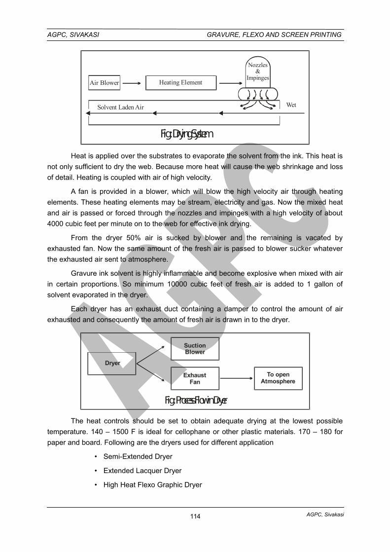
AGPC, Sivakasi
AGPC, SIVAKASI GRAVURE, FLEXO AND SCREEN PRINTING
Air Blower Heating Element
Nozzles&
Impinges
Solvent Laden Air Wet
Fig : Drying System
Heat is applied over the substrates to evaporate the solvent from the ink. This heat is
not only sufficient to dry the web. Because more heat will cause the web shrinkage and loss
of detail. Heating is coupled with air of high velocity.
A fan is provided in a blower, which will blow the high velocity air through heating
elements. These heating elements may be stream, electricity and gas. Now the mixed heat
and air is passed or forced through the nozzles and impinges with a high velocity of about
4000 cubic feet per minute on to the web for effective ink drying.
From the dryer 50% air is sucked by blower and the remaining is vacated by
exhausted fan. Now the same amount of the fresh air is passed to blower sucker whatever
the exhausted air sent to atmosphere.
Gravure ink solvent is highly inflammable and become explosive when mixed with air
in certain proportions. So minimum 10000 cubic feet of fresh air is added to 1 gallon of
solvent evaporated in the dryer.
Each dryer has an exhaust duct containing a damper to control the amount of air
exhausted and consequently the amount of fresh air is drawn in to the dryer.
Dryer
SuctionBlower
ExhaustFan
To open Atmosphere
Fig : Process Flow in Dryer
The heat controls should be set to obtain adequate drying at the lowest possible
temperature. 140 – 1500 F is ideal for cellophane or other plastic materials. 170 – 180 for
paper and board. Following are the dryers used for different application
• Semi-Extended Dryer
• Extended Lacquer Dryer
• High Heat Flexo Graphic Dryer
114
AGPC, Sivakasi
AGPC, SIVAKASI GRAVURE, FLEXO AND SCREEN PRINTING
All dryers’ uses air as a heat transfer medium for varying types of inks, coating and
liquids. In certain specialized job for drying and heating, infrared (IR), Ultraviolet (UV), Radio
Frequency (RF), Microwave (MW) and Electron Beam (EB) drying methods are used.
4.2.3. GRAVURE SOLVENT RECOVERY SYSTEM
Solvent recovery system removes solvent fumes from- the dryer exhaust air andcollects the solvent for reuse. Solvent recovery systems are excellent for multiple pressoperations where the solvents be selected for easy recovery and reuse. Publication gravureliters use solvent recovery systems almost exclusively. The recovered solvent costs only afraction of the cost of new solvent and helps to offset the cost of the solvent recoveryequipment.
Solvent recovery for packaging and product gravure operations more difficultbecause of the variety of solvents used in the ink and coating formulations. Recoveredsolvent requires further treatment before it can be reused. This often increases the costabove the cost of new solvent. Solvent recovery is very rarely cost effective for packagingand product printers running multiple solvents.
The purpose of a solvent recovery system is to remove evaporated solvents fromdryer exhaust air and the press room air and collecting the solvent for reuse. During therecovery process, the solvent undergoes a number of transformations, described below.
Solvent-laden air is drawn from the dryer by large fans. The air is channeled throughduct work to one or several adsorbers beds of activated carbon pellets. The pellets adsorbthe solvent as the air forced through them. The cleansed air passes out of the adsorber andinto the atmosphere.
After the carbon bed is reasonably saturated with solvent, steam is forced into theadsorber. This drives the solvent vapor backout of the carbon and into the steam.
The solvent vapor-steam mixture is then cooled and condensed into a liquid state.When this mixture is piped into a decant tank, the solvent and water separate into distinctlayers solvent is lighter than water). The solvent is siphoned off the top into a collection tank,from which it is returned to solvent storage or reuse. The water layer is removed to acollection tank for disposal or reuse.
The nonpolar solvents used in publication gravure are essentially not miscible withwater. Thus, the recovered solvent is water-free and can be reused directly. The recoveredwater, however, may contain traces of solvent which have to be removed by air stripping orliquid phase carbon adsorption.
Packaging and product gravure operations use polar solvents or mixtures containingpolar solvents. These are atleast partially miscible with water, and does the recovery solventcontains water and the decant water condensate contains solvent. The degree to which thewater has to be removed from the solvent before reuse depends on the nature of thesolvent, and the ink system’s tolerance for water. Purification of decant water is governed bythe method of disposal and local regulations.
Solvent recovery is appropriate for multiple press operations where solvents arenecessary, and where the solvents can be selected for easy recovery and re-use as a
115
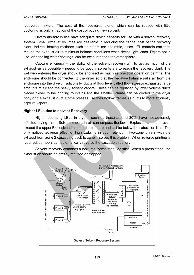
AGPC, Sivakasi
AGPC, SIVAKASI GRAVURE, FLEXO AND SCREEN PRINTING
recovered mixture. The cost of the recovered blend, which can be reused with littledoctoring, is only a fraction of the cost of buying new solvent.
Dryers already in use have adequate drying capacity for use with a solvent recoverysystem. Small exhaust volumes are desirable in reducing the capital cost of the recoveryplant. Indirect heating methods such as steam are desirable, since LEL controls can thenreduce the exhaust air to minimum balance conditions when drying light loads. Dryers not inuse, or handling water coatings, can be exhausted top the atmosphere.
Capture efficiency – the ability of the solvent recovery unit to get as much of theexhaust air as possible – needs to be good if solvents are to reach the recovery plant. Thewet web entering the dryer should be enclosed as much as practical operation permits. Theenclosure should be connected to the dryer so that the negative balance pulls air from theenclosure into the dryer. Traditionally, ducts at floor level called floor sweeps exhausted largeamounts of air and the heavy solvent vapors. These can be replaced by lower volume ductsplaced closer to the printing fountains and the smaller volume can be ducted to the dryerbody or the exhaust duct. Some presses use their hollow frames as ducts to more efficientlycapture vapors.
Higher LELs due to solvent Recovery
Higher operating LELs in dryers, such as those around 30%, have not adverselyaffected drying rates. Solvent vapors in air can surpass the lower Explosion Limit and evenexceed the upper Explosion Limit (too rich to burn) and still be below the saturation limit. Theonly noticed adverse effect of high LELs is in odor retention. Two-zone dryers with theexhaust from zone 2 cascading back to zone 1 solves this problem. When reverse printing isrequired, dampers can automatically reverse the cascade direction.
Solvent recovery demands a look into “press stop” logistics. When a press stops, theexhaust air should be greatly reduced or stopped.
Press 1(Typical)
Dryer
RoomAir In
Press 2
Press 3
Press 4So
lven
t to
Pre
sses
(In
k D
ilue
nt)
Dryer Exhaustto Adsorber
Steam inDuring steam-
ing Cycle Fixed CarbonBed Adsorber
Steam andSolvent
Vapour to Condenser
DuringRegeneration
Clean Air to AtmosphereDuring Adsorption Cycle
CoolingTower
Co
nd
ense
r Mixture ofWater and
Solvent
Solvent
Water
Decanter
Ma
ke U
p W
ate
r to
Co
olin
g T
ow
er
Gravure Solvent Recovery System
116
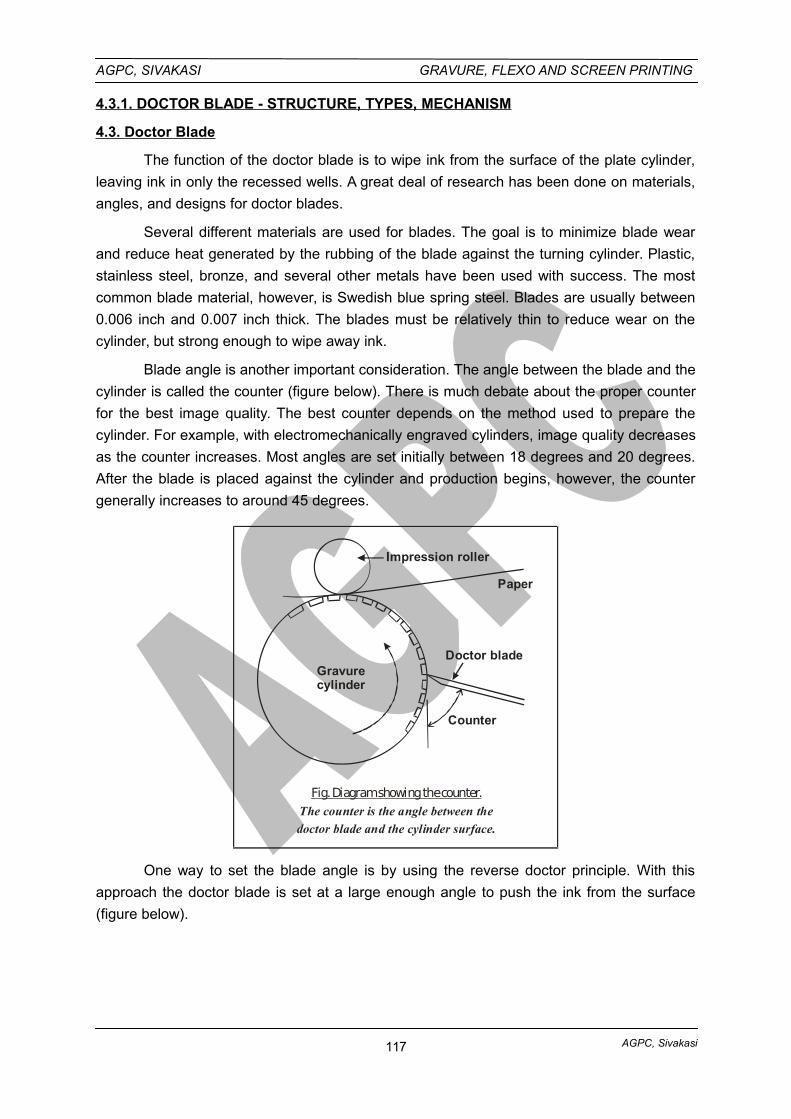
AGPC, Sivakasi
AGPC, SIVAKASI GRAVURE, FLEXO AND SCREEN PRINTING
4.3.1. DOCTOR BLADE - STRUCTURE, TYPES, MECHANISM
4.3. Doctor Blade
The function of the doctor blade is to wipe ink from the surface of the plate cylinder,
leaving ink in only the recessed wells. A great deal of research has been done on materials,
angles, and designs for doctor blades.
Several different materials are used for blades. The goal is to minimize blade wear
and reduce heat generated by the rubbing of the blade against the turning cylinder. Plastic,
stainless steel, bronze, and several other metals have been used with success. The most
common blade material, however, is Swedish blue spring steel. Blades are usually between
0.006 inch and 0.007 inch thick. The blades must be relatively thin to reduce wear on the
cylinder, but strong enough to wipe away ink.
Blade angle is another important consideration. The angle between the blade and the
cylinder is called the counter (figure below). There is much debate about the proper counter
for the best image quality. The best counter depends on the method used to prepare the
cylinder. For example, with electromechanically engraved cylinders, image quality decreases
as the counter increases. Most angles are set initially between 18 degrees and 20 degrees.
After the blade is placed against the cylinder and production begins, however, the counter
generally increases to around 45 degrees.
Paper
Impression roller
Gravurecylinder
Doctor blade
Counter
Fig. Diagram showing the counter.The counter is the angle between the
doctor blade and the cylinder surface.
One way to set the blade angle is by using the reverse doctor principle. With this
approach the doctor blade is set at a large enough angle to push the ink from the surface
(figure below).
117
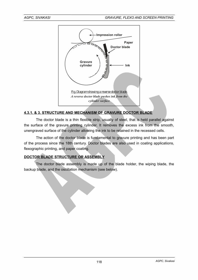
AGPC, Sivakasi
AGPC, SIVAKASI GRAVURE, FLEXO AND SCREEN PRINTING
Fig. Diagram showing a reverse doctor blade.A reverse doctor blade pushes ink from the
cylinder surface
Paper
Impression roller
Gravurecylinder
Doctor blade
Ink
4.3.1. & 3. STRUCTURE AND MECHANISM OF GRAVURE DOCTOR BLADE
The doctor blade is a thin flexible strip, usually of steel, that is held parallel against
the surface of the gravure printing cylinder. It removes the excess ink from the smooth,
unengraved surface of the cylinder allowing the ink to be retained in the recessed cells.
The action of the doctor blade is fundamental to gravure printing and has been part
of the process since the 18th century. Doctor blades are also used in coating applications,
flexographic printing, and paper coating.
DOCTOR BLADE STRUCTURE OR ASSEMBLY
The doctor blade assembly is made up of the blade holder, the wiping blade, the
backup blade, and the oscillation mechanism (see below).
118
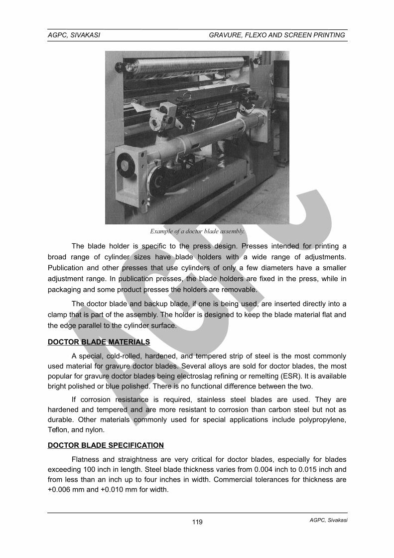
AGPC, Sivakasi
AGPC, SIVAKASI GRAVURE, FLEXO AND SCREEN PRINTING
Example of a doctor blade assembly.
The blade holder is specific to the press design. Presses intended for printing a
broad range of cylinder sizes have blade holders with a wide range of adjustments.
Publication and other presses that use cylinders of only a few diameters have a smaller
adjustment range. In publication presses, the blade holders are fixed in the press, while in
packaging and some product presses the holders are removable.
The doctor blade and backup blade, if one is being used, are inserted directly into a
clamp that is part of the assembly. The holder is designed to keep the blade material flat and
the edge parallel to the cylinder surface.
DOCTOR BLADE MATERIALS
A special, cold-rolled, hardened, and tempered strip of steel is the most commonlyused material for gravure doctor blades. Several alloys are sold for doctor blades, the mostpopular for gravure doctor blades being electroslag refining or remelting (ESR). It is availablebright polished or blue polished. There is no functional difference between the two.
If corrosion resistance is required, stainless steel blades are used. They arehardened and tempered and are more resistant to corrosion than carbon steel but not asdurable. Other materials commonly used for special applications include polypropylene,Teflon, and nylon.
DOCTOR BLADE SPECIFICATION
Flatness and straightness are very critical for doctor blades, especially for bladesexceeding 100 inch in length. Steel blade thickness varies from 0.004 inch to 0.015 inch andfrom less than an inch up to four inches in width. Commercial tolerances for thickness are+0.006 mm and +0.010 mm for width.
119
AGPC, Sivakasi
AGPC, SIVAKASI GRAVURE, FLEXO AND SCREEN PRINTING
The backup blade is used to give the doctor blade additional support. When set upproperly it creates a spring action when the doctor blade is applied to the cylinder. Stiffnesscan be adjusted by changing how far the doctor blade is extended beyond the backup lade.Excessive cylinder wear and premature blade wear will result if the blade setup is too stiff. Ifthe blade setup is not stiff enough, there will be excess sensitivity to contact angle, pressure,and press peed. Backup blades are typically 0.010-0.015 inch thick.
WIPING ANGLES
Setting the blade refers to the action of bringing the doctor blade in contact with theengraved cylinder at the best angle and pressure necessary to completely wipe the excessink from the cylinder. There are two important angles that the press operator must considerwhen setting a doctor blade, the set angle and the contact angle. The set angle is actually areference angle. Some presses are equipped with instruments that can be used to achieve apre-determined set angle. The contact angle is the net result of all the forces applied to thedoctor blade when it is in operation. Manufacturers recommend a contact angle of between55-65° for optimum wiping performance. When pressure is applied to the doctor blade at thestart of the pressrun, a certain amount of force is required to keep the blade in contact withthe cylinder. The ink being wiped from the cylinder surface can apply hydraulic forcesagainst the blade causing it to lift up and away from the cylinder. To alleviate this condition,some printing units are equipped with pre-wiping, non-contact blades that reduce thehydraulic pressure created on high-speed presses.
DOCTOR BLADE WEAR
ADHESIVE WEAR
Gravure inks provide the lubrication necessary to minimize blade and cylinder wear.The doctor blade actually rides on a thin film of ink. The cylinder surface is not wipedcompletely, but is sufficiently cleaned so that the remaining ink film will not transfer to thesubstrate. Adhesive wear occurs when the ink film fails to separate the blade from thecylinder.
ABRASIVE WEAR
This type of wear takes place whenever hard foreign particles are present betweenthe blade and the engraved cylinder. Potential sources of abrasive particles include inkpigment, dried ink, rust, paper dust, particles of paper coating, doctor blade particles, andchrome flakes from the printing cylinder. Gravure ink pumping systems are equipped withfilters to remove potentially abrasive materials from the ink before they can cause damage tothe blade or cylinder.
One of the most common print defects unique to gravure is the doctor blade streak.
Despite the many precautions taken in press design and ink handling, occasionally a foreign
particle will get lodged under the doctor blade, causing a streak. Proper blade oscillation can
minimize this problem and reduce cylinder wear.
Cylinder finish is also a factor in print defects. A certain amount of roughness can
actually improve lubricity and doctor blade performance. The best surface finish will take into
account the type of ink and solvent being used, the press speed, and the substrate. The
120
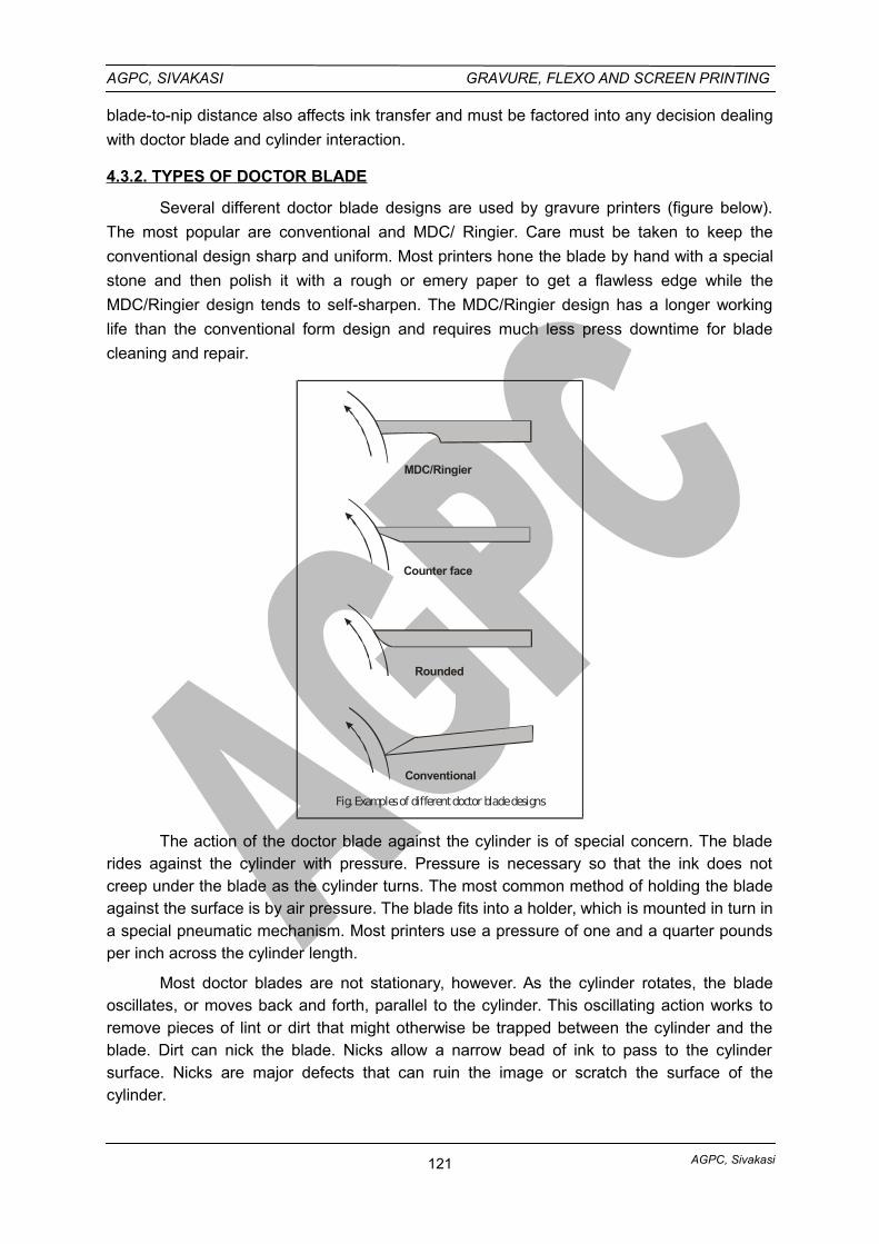
AGPC, Sivakasi
AGPC, SIVAKASI GRAVURE, FLEXO AND SCREEN PRINTING
blade-to-nip distance also affects ink transfer and must be factored into any decision dealing
with doctor blade and cylinder interaction.
4.3.2. TYPES OF DOCTOR BLADE
Several different doctor blade designs are used by gravure printers (figure below).
The most popular are conventional and MDC/ Ringier. Care must be taken to keep the
conventional design sharp and uniform. Most printers hone the blade by hand with a special
stone and then polish it with a rough or emery paper to get a flawless edge while the
MDC/Ringier design tends to self-sharpen. The MDC/Ringier design has a longer working
life than the conventional form design and requires much less press downtime for blade
cleaning and repair.
MDC/Ringier
Counter face
Rounded
Conventional
Fig. Examples of different doctor blade designs
The action of the doctor blade against the cylinder is of special concern. The bladerides against the cylinder with pressure. Pressure is necessary so that the ink does notcreep under the blade as the cylinder turns. The most common method of holding the bladeagainst the surface is by air pressure. The blade fits into a holder, which is mounted in turn ina special pneumatic mechanism. Most printers use a pressure of one and a quarter poundsper inch across the cylinder length.
Most doctor blades are not stationary, however. As the cylinder rotates, the bladeoscillates, or moves back and forth, parallel to the cylinder. This oscillating action works toremove pieces of lint or dirt that might otherwise be trapped between the cylinder and theblade. Dirt can nick the blade. Nicks allow a narrow bead of ink to pass to the cylindersurface. Nicks are major defects that can ruin the image or scratch the surface of thecylinder.
121
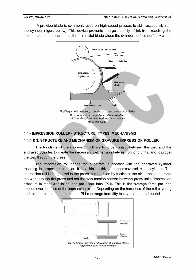
AGPC, Sivakasi
AGPC, SIVAKASI GRAVURE, FLEXO AND SCREEN PRINTING
A prewipe blade is commonly used on high-speed presses to skim excess ink fromthe cylinder (figure below). This device prevents a large quantity of ink from reaching thedoctor blade and ensures that the thin metal blade wipes the cylinder surface perfectly clean.
Fig. Diagram of a gravure cylinder showing prewipe and doctor blades.Most presses use prewipe blades skin most of theink from the cylinder before the cylinder reaches
the doctor blade.
Impression roller
Paper
Doctor blade
Pre wipe blade
InkInk fountain
GravureCylinder
4.4 - IMPRESSION ROLLER - STRUCTURE, TYPES, MECHANISMS
4.4.1 & 3. STRUCTURE AND MECHANISM OF GRAVURE IMPRESSION ROLLER
The functions of the impression roll are to force contact between the web and theengraved cylinder, to create the necessary web tension between printing units, and to propelthe web through the press.
The impression roll brings the substrate in contact with the engraved cylinderresulting in proper ink transfer. It is a friction-driven, rubber-covered metal cylinder. Theimpression roll is not geared to the press, but is driven by friction at the nip. It helps to propelthe web through the press and set the web tension pattern between press units. Impressionpressure is measured in pounds per linear inch (PLI). This is the average force per inchapplied over the face of the impression roller. Depending on the hardness of the roll coveringand the substrate to be printed, the PLI can range from fifty to several hundred pounds.
Fig. The typical impression roll consists of a tubular sleeve,supported at each end on bearings
122
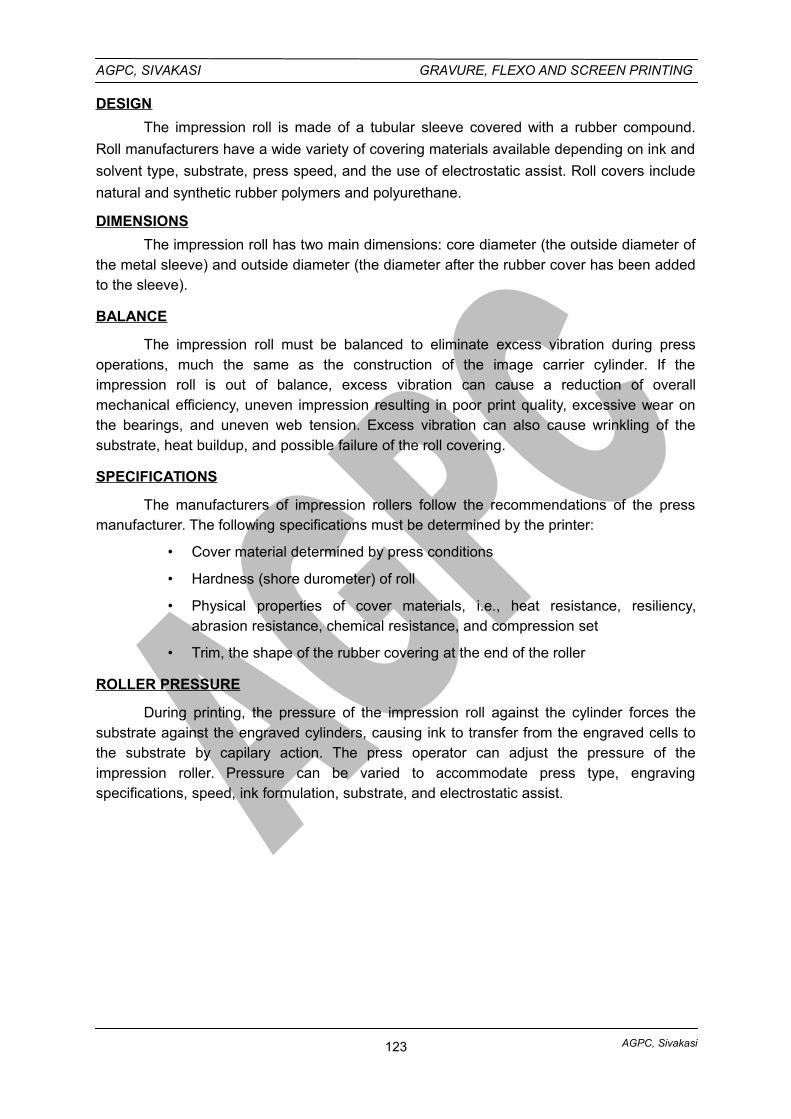
AGPC, Sivakasi
AGPC, SIVAKASI GRAVURE, FLEXO AND SCREEN PRINTING
DESIGN
The impression roll is made of a tubular sleeve covered with a rubber compound.
Roll manufacturers have a wide variety of covering materials available depending on ink and
solvent type, substrate, press speed, and the use of electrostatic assist. Roll covers include
natural and synthetic rubber polymers and polyurethane.
DIMENSIONS
The impression roll has two main dimensions: core diameter (the outside diameter ofthe metal sleeve) and outside diameter (the diameter after the rubber cover has been addedto the sleeve).
BALANCE
The impression roll must be balanced to eliminate excess vibration during pressoperations, much the same as the construction of the image carrier cylinder. If theimpression roll is out of balance, excess vibration can cause a reduction of overallmechanical efficiency, uneven impression resulting in poor print quality, excessive wear onthe bearings, and uneven web tension. Excess vibration can also cause wrinkling of thesubstrate, heat buildup, and possible failure of the roll covering.
SPECIFICATIONS
The manufacturers of impression rollers follow the recommendations of the pressmanufacturer. The following specifications must be determined by the printer:
• Cover material determined by press conditions
• Hardness (shore durometer) of roll
• Physical properties of cover materials, i.e., heat resistance, resiliency,abrasion resistance, chemical resistance, and compression set
• Trim, the shape of the rubber covering at the end of the roller
ROLLER PRESSURE
During printing, the pressure of the impression roll against the cylinder forces thesubstrate against the engraved cylinders, causing ink to transfer from the engraved cells tothe substrate by capilary action. The press operator can adjust the pressure of theimpression roller. Pressure can be varied to accommodate press type, engravingspecifications, speed, ink formulation, substrate, and electrostatic assist.
123
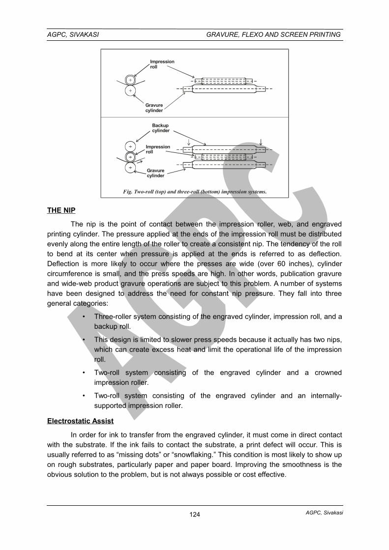
AGPC, Sivakasi
AGPC, SIVAKASI GRAVURE, FLEXO AND SCREEN PRINTING
Impressionroll
Gravurecylinder
Backupcylinder
Fig. Two-roll (top) and three-roll (bottom) impression systems.
Impressionroll
Gravurecylinder
THE NIP
The nip is the point of contact between the impression roller, web, and engravedprinting cylinder. The pressure applied at the ends of the impression roll must be distributedevenly along the entire length of the roller to create a consistent nip. The tendency of the rollto bend at its center when pressure is applied at the ends is referred to as deflection.Deflection is more likely to occur where the presses are wide (over 60 inches), cylindercircumference is small, and the press speeds are high. In other words, publication gravureand wide-web product gravure operations are subject to this problem. A number of systemshave been designed to address the need for constant nip pressure. They fall into threegeneral categories:
• Three-roller system consisting of the engraved cylinder, impression roll, and abackup roll.
• This design is limited to slower press speeds because it actually has two nips,which can create excess heat and limit the operational life of the impressionroll.
• Two-roll system consisting of the engraved cylinder and a crownedimpression roller.
• Two-roll system consisting of the engraved cylinder and an internally-supported impression roller.
Electrostatic Assist
In order for ink to transfer from the engraved cylinder, it must come in direct contactwith the substrate. If the ink fails to contact the substrate, a print defect will occur. This isusually referred to as “missing dots” or “snowflaking.” This condition is most likely to show upon rough substrates, particularly paper and paper board. Improving the smoothness is theobvious solution to the problem, but is not always possible or cost effective.
124
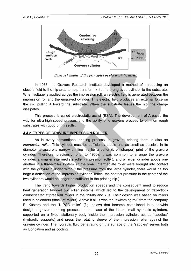
AGPC, Sivakasi
AGPC, SIVAKASI GRAVURE, FLEXO AND SCREEN PRINTING
Basic schematic of the principles of electrostatic assist.
In 1966, the Gravure Research Institute developed a method of introducing anelectric field to the nip area to help transfer ink from the engraved cylinder to the substrate.When voltage is applied across the impression roll, an electric field is generated between theimpression roll and the engraved cylinder. This electric field produces an external force onthe ink, pulling it toward the substrate. When the substrate leaves the nip, the chargedissipates.
This process is called electrostatic assist (ESA). The development of A paved theway for ultra-high-speed presses and the ability of e gravure process to print on roughsubstrates with good print results.
4.4.2. TYPES OF GRAVURE IMPRESSION ROLLER
As in every conventional printing process, in gravure printing there is also animpression roller. This cylinder must be sufficiently stable and as small as possible in itsdiameter to assure a narrow printing nip for a better (i. e., sharper) print of the gravurecylinder. Therefore, previously (prior to 1960), it was common to arrange the gravurecylinder, a smaller intermediate roller (impression roller), and a larger cylinder above oneanother in a three-roller system. (If the small intermediate roller were brought into contactwith the gravure cylinder without the pressure from the large cylinder, there would be toolarge a deflection of the impression cylinder.Hence, the contact pressure in the center of thetwo cylinders would no longer be sufficient in the printing nip.)
The trend towards higher production speeds and the consequent need to reduceheat generation favored two roller systems, which led to the development of deflection-compensated impression rollers in the 1960s and 70s. Their design was based on rollersused in calenders (stack of rollers). Above it all, it was the “swimming roll” from the companyE. Küsters and the “NIPCO roller” (fig. below) that became established in superwidedesigned gravure printing presses. In the case of the latter, small hydraulic cylinders,supported on a fixed, stationary body inside the impression cylinder, act as “saddles”(hydraulic supports) and press the rotating sleeve of the impression roller against thegravure cylinder. The hydraulic fluid penetrating on the surface of the “saddles” serves bothas lubrication and as cooling.
125
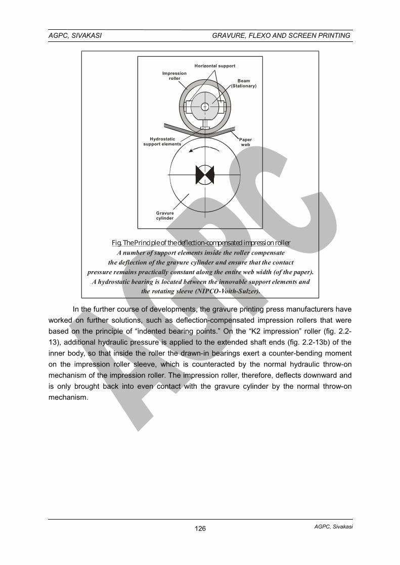
AGPC, Sivakasi
AGPC, SIVAKASI GRAVURE, FLEXO AND SCREEN PRINTING
Paperweb
Gravurecylinder
Hydrostaticsupport elements
Impressionroller
Horizontal support
Beam(Stationary)
Fig. The Principle of the deflection-compensated impression rollerA number of support elements inside the roller compensate
the deflection of the gravure cylinder and ensure that the contact
pressure remains practically constant along the entire web width (of the paper).
A hydrostatic bearing is located between the innovable support elements andthe rotating sleeve (NIPCO-Voith-Sulzer).
In the further course of developments, the gravure printing press manufacturers have
worked on further solutions, such as deflection-compensated impression rollers that were
based on the principle of “indented bearing points.” On the “K2 impression” roller (fig. 2.2-
13), additional hydraulic pressure is applied to the extended shaft ends (fig. 2.2-13b) of the
inner body, so that inside the roller the drawn-in bearings exert a counter-bending moment
on the impression roller sleeve, which is counteracted by the normal hydraulic throw-on
mechanism of the impression roller. The impression roller, therefore, deflects downward and
is only brought back into even contact with the gravure cylinder by the normal throw-on
mechanism.
126
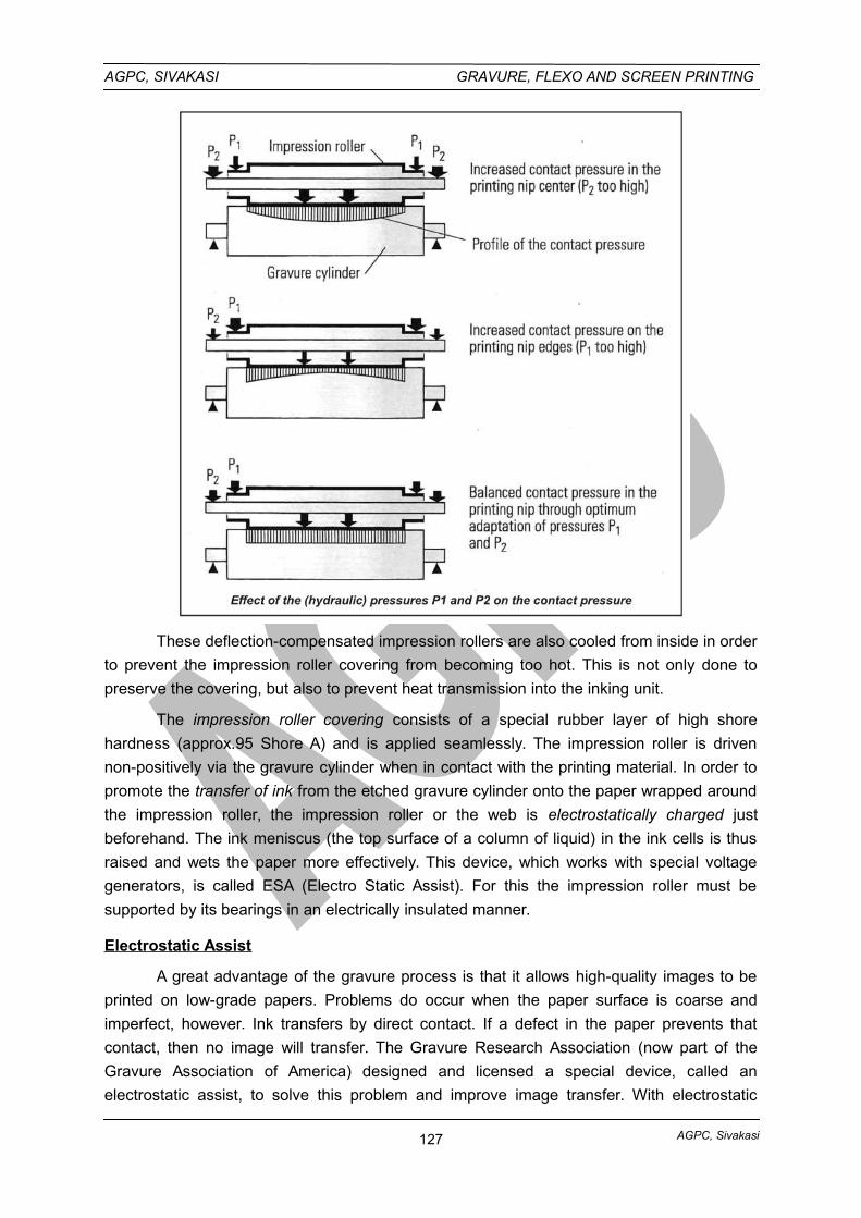
AGPC, Sivakasi
AGPC, SIVAKASI GRAVURE, FLEXO AND SCREEN PRINTING
These deflection-compensated impression rollers are also cooled from inside in order
to prevent the impression roller covering from becoming too hot. This is not only done to
preserve the covering, but also to prevent heat transmission into the inking unit.
The impression roller covering consists of a special rubber layer of high shore
hardness (approx.95 Shore A) and is applied seamlessly. The impression roller is driven
non-positively via the gravure cylinder when in contact with the printing material. In order to
promote the transfer of ink from the etched gravure cylinder onto the paper wrapped around
the impression roller, the impression roller or the web is electrostatically charged just
beforehand. The ink meniscus (the top surface of a column of liquid) in the ink cells is thus
raised and wets the paper more effectively. This device, which works with special voltage
generators, is called ESA (Electro Static Assist). For this the impression roller must be
supported by its bearings in an electrically insulated manner.
Electrostatic Assist
A great advantage of the gravure process is that it allows high-quality images to be
printed on low-grade papers. Problems do occur when the paper surface is coarse and
imperfect, however. Ink transfers by direct contact. If a defect in the paper prevents that
contact, then no image will transfer. The Gravure Research Association (now part of the
Gravure Association of America) designed and licensed a special device, called an
electrostatic assist, to solve this problem and improve image transfer. With electrostatic
127
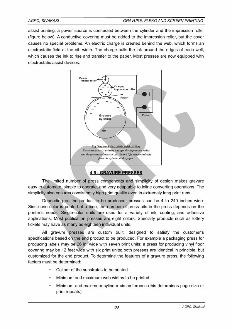
AGPC, Sivakasi
AGPC, SIVAKASI GRAVURE, FLEXO AND SCREEN PRINTING
assist printing, a power source is connected between the cylinder and the impression roller
(figure below). A conductive covering must be added to the impression roller, but the cover
causes no special problems. An electric charge is created behind the web, which forms an
electrostatic field at the nib width. The charge pulls the ink around the edges of each well,
which causes the ink to rise and transfer to the paper. Most presses are now equipped with
electrostatic assist devices.
Gravurecylinder
Chargedimpression roller
Paper
Power
PowerTransfer roller
Fig. Diagram of electrostatic assist printing.Electrostatic assist printing charges the impression roller
and the gravure cylinder so that the ink lifts electrostaticallyfrom the cylinder to the paper.
4.5 - GRAVURE PRESSES
The limited number of press components and simplicity of design makes gravureeasy to automate, simple to operate, and very adaptable to inline converting operations. Thesimplicity also ensures consistently high print quality even in extremely long print runs.
Depending on the product to be produced, presses can be 4 to 240 inches wide.Since one color is printed at a time, the number of press pits in the press depends on theprinter’s needs. Single-color units are used for a variety of ink, coating, and adhesiveapplications. Most publication presses are eight colors. Specialty products such as lotterytickets may have as many as eighteen individual units.
All gravure presses are custom built, designed to satisfy the customer’sspecifications based on the end product to be produced. For example a packaging press forproducing labels may be 26 in. wide with seven print units; a press for producing vinyl floorcovering may be 12 feet wide with six print units; both presses are identical in principle, butcustomized for the end product. To determine the features of a gravure press, the followingfactors must be determined:
• Caliper of the substrates to be printed
• Minimum and maximum web widths to be printed
• Minimum and maximum cylinder circumference (this determines page size orprint repeats)
128
AGPC, Sivakasi
AGPC, SIVAKASI GRAVURE, FLEXO AND SCREEN PRINTING
• Press speed as determined by in-line converting operations
• Tension ranges based on the physical characteristics of the substrates to beprinted
• Number of print units
• Dryers sized and zoned to handle press speed, substrate, and the type ofinks and coatings to be applied
• Infeed unit determined by the specific needs of the substrates to be handled
• Outfeed unit determined by the substrate and the in-line convertingoperations following the last print unit
• Drives, the power source determined by substrate, press speed, and tensionranges
• Controls, determined by the amount of automation desired (these include on-line video monitoring, register controls, preset job setup, production statistics,waste analysis, electrostatic assist, automated ink dispensing and viscositycontrol, and a long list of other on-line controls to assist in pressroommanagement.)
SECTIONS OF THE PRESS
SUBSTRATE SUPPLY
The substrate supply section includes the reel stand web guide, pre-treatment andinfeed tension control. All web-fed gravure presses start from a reel stand that unwinds theroll of substrate to be printed. The infeed is critical for web and tension control throughoutthe rest of the press. High-speed presses have what is called a two-position reel stand. Thisallows two rolls of substrate to be mounted on the press at one time. For presses printinglight weight materials, the unwind unit is equipped to splice a new roll to the end of theexpiring roll. This allows continuous operation of the press when the rolls are splicedtogether. Presses printing heavyweight material such as sheet vinyl or thick board have aweb accumulator or festoon that is described in detail later in this chapter.
GRAVURE PRINTING UNIT
At the heart of the gravure press is the printing unit. It contains the following five
basic components regardless of the application:
• The engraved cylinder (image carrier)
• An ink fountain, a large pan positioned beneath the cylinder that extends thewidth of the printing unit
• A doctor blade assembly consisting of a doctor blade, doctor blade holder,and oscillation mechanism
• An impression system to hold the substrate against the engraved cylinder tofacilitate ink transfer
• A dryer that provides heated air to dry the moving web before it enters thenext printing unit
129
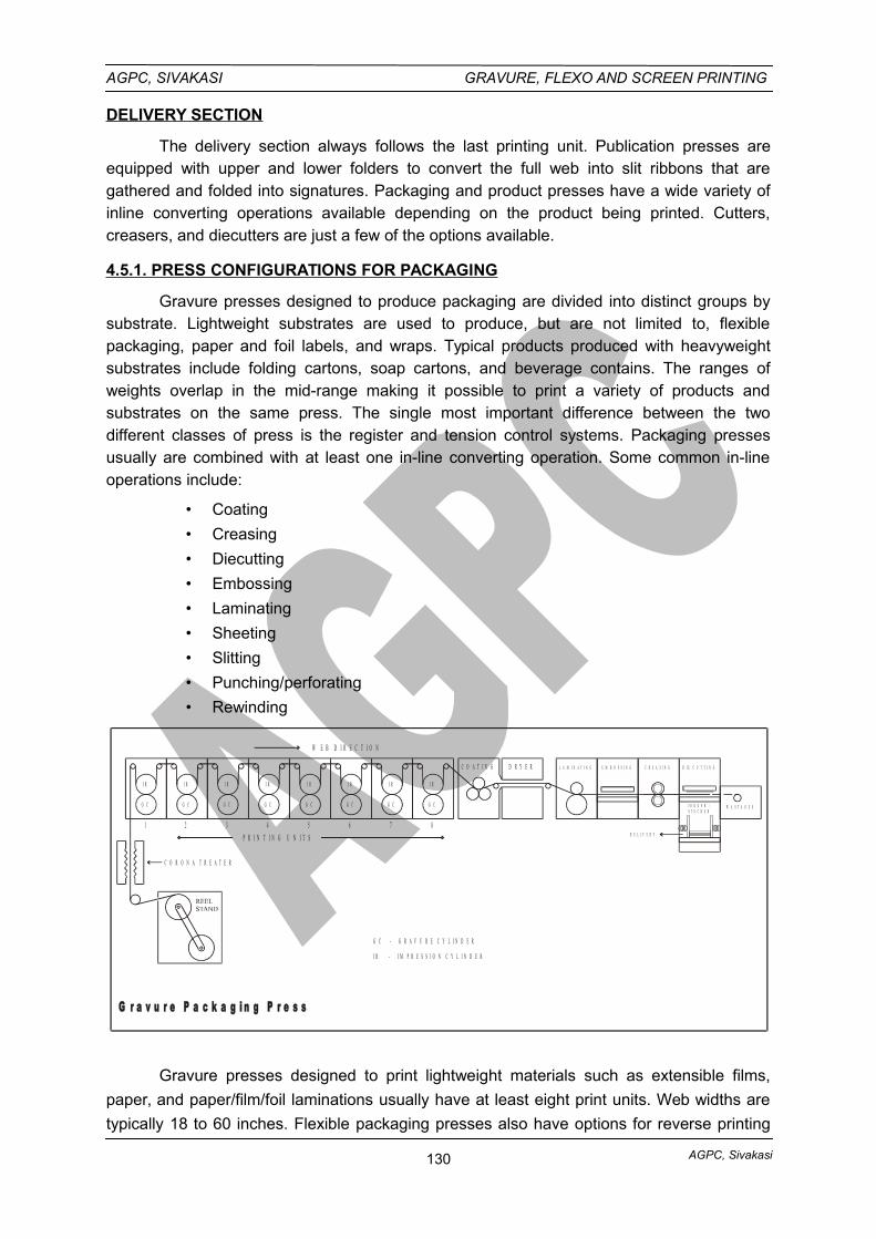
AGPC, Sivakasi
AGPC, SIVAKASI GRAVURE, FLEXO AND SCREEN PRINTING
DELIVERY SECTION
The delivery section always follows the last printing unit. Publication presses areequipped with upper and lower folders to convert the full web into slit ribbons that aregathered and folded into signatures. Packaging and product presses have a wide variety ofinline converting operations available depending on the product being printed. Cutters,creasers, and diecutters are just a few of the options available.
4.5.1. PRESS CONFIGURATIONS FOR PACKAGING
Gravure presses designed to produce packaging are divided into distinct groups bysubstrate. Lightweight substrates are used to produce, but are not limited to, flexiblepackaging, paper and foil labels, and wraps. Typical products produced with heavyweightsubstrates include folding cartons, soap cartons, and beverage contains. The ranges ofweights overlap in the mid-range making it possible to print a variety of products andsubstrates on the same press. The single most important difference between the twodifferent classes of press is the register and tension control systems. Packaging pressesusually are combined with at least one in-line converting operation. Some common in-lineoperations include:
• Coating
• Creasing
• Diecutting
• Embossing
• Laminating
• Sheeting
• Slitting
• Punching/perforating
• Rewinding
I R I R I R
G C G C G C
I R I R I R I R
G C G C G C G C
C O A T I N G D R Y E R
2 3 4 5 6 7 8
C O R O N A T R E A T E R
P R I N T I N G U N I T S
W E B D I R E C T I O N
L A M I N A T I N G E M B O S S I N G C R E A S I N G D I E C U T T I N G
J O G G E R / S T A C K E R
D E L I V E R Y
G r a v u r e P a c k a g i n g P r e s s
I R
G C
1
W A S T A G E S
G C - G R A V U R E C Y L I N D E R
I R - I M P R E S S I O N C Y L I N D E R
Gravure presses designed to print lightweight materials such as extensible films,
paper, and paper/film/foil laminations usually have at least eight print units. Web widths are
typically 18 to 60 inches. Flexible packaging presses also have options for reverse printing
130
AGPC, Sivakasi
AGPC, SIVAKASI GRAVURE, FLEXO AND SCREEN PRINTING
units, preconditioning systems to heat the substrate before printing, and cooling units or chill
rollers to cool temperature-sensitive films and laminations. Corona treaters can also be
added before printing to insure good ink and coating adhesion.
Presses designed to handle heavy substrates must have reel stands designed to
handle the weight of the substrates. Presses in this group are typically built between 44 to
216 inches wide. They run at slower speeds than presses running lightweight substrates. A
folding carton press with an in-line cutter/creaser will generally run at 600 to 800 feet per
minute.
SPLICING
Splicing is the attachment of a new roll of substrate to the end of an expiring roll. If
the press is equipped with a rewind unit for the printed web, it will also be equipped with a
splicing unit. Because of the variety of substrates, there are varieties of splicing options
available. There are two basic types of splices: the lap splice and the butt splice. For flexible
materials of low caliper (i.e., films, foil, laminations, and papers), a lap splice is
recommended.
A lap splice involves joining a new roll to the expiring roll by gluing, done at the
operating speed of the press. It is often referred to as a flying splice, meaning that rolls are
joined “on the fly.” Maintaining good tension and register control as the splice moves through
the printing units is necessary to avoid unnecessary waste.
A butt splice involves joining two webs with tape. They are butted end to end rather
than overlapping because of the thickness of the substrate. To make a butt splice while the
press is running, the press is equipped with a festoon.
The festoon is a series of rolls following the unwind section of the press that
gradually collapse to continue feeding substrate through the press when the unwind is
momentarily stopped to execute a butt splice. When the splice is completed, the festoon rolls
gradually return to their original position, ready for the next splice.
Typically applications for gravure package printing include folding cartons, flexible
packaging and gravure labels and wraps. Each of these applications makes special
demands of the gravure press, in addition to different requirements for in-line finishing.
Folding Carton Presses:
Folding carton press typically have from six to eight printing units and are available in
either narrow (under 36 inches) or wide web (up to 55 inches) with variable cut off (repeat) in
diameter ranges. Compared to the generic press, a folding carton press is designed to print
board from 9 to 40 points thick, the same press can also be used to print paper as low as 60
lb. Per ream. In order to design a folding carton press, the following specifications need to be
identified:
131
AGPC, Sivakasi
AGPC, SIVAKASI GRAVURE, FLEXO AND SCREEN PRINTING
• Reel stand is sized to handle the maximum diameter and weight of the rolls ofsubstrate to be printed. Rolls of board, depending on thickness, can reach upto 84 inches in diameter, where paper is usually packaged in up to 50 – inchO.D. rolls.
• Printing units and cut off ranges must also be determined by the range ofsubstrate to be printed. Other printing unit specs include web width, maximumprint width, printing speed, in fountain capacity, and whether one or both sidesof the web will be printed.
• Dryers are specified for maximum air flow, temperature of drying air, and weblength between printing nips, from printing nip to outlet roller, and length ofweb in the dryer.
Folding carton presses offer a variety of in-line converting operation. They include:
Cutter / creasers for folding carton production.
Sheeter.
Rewinder for production of miscellaneous printed paper and board products
that can be converted in an off-line cut – to – print unit. Sheeters andrewinders can both be incorporated at the end of press and usedinterchangeably depending on the end product.
Rotary die cutter.
Rotary embosser.
Pre conditioning systems installed at the unwinder exit are:
• A heated drum followed by a chill roller, is frequently used for presses
designed for printing both film and paper.
• A preconditioning chamber, which blows hot air are steamed onto the web.
• A decurling device.
• A web cleaner.
Flexible Packaging Presses
Flexible packaging presses typically have eight printing units, but have been with asmany as 11 units. Web widths range from under 12 inches to 63 inches, with variable repeat(cutoff) in diameter ranges. The flexible packaging press is designed to print light weightextensible films, paper and laminations (film / foil / paper combinations). In order to design aflexible packaging press, the following specifications need to be identified:
132
AGPC, Sivakasi
AGPC, SIVAKASI GRAVURE, FLEXO AND SCREEN PRINTING
• Reel stands. The reel stand is designed for the range of weight of substratesto be handled. Flexible substrates tend to come in rolls of 50 inches or less indiameter, and are quite heavy when compared to similar size rolls of paper orboard.
• Printing Units and Cut offs. Printing units and repeat length (cutoff) rangesmust also be determined by the range of substrates to be printed. Otherprinting unit specs include web width, maximum print width, printing speed,ink fountain capacity, and whether the web will be printed on one or bothsides.
• Dryers. Dryers are specified for maximum air flow, temperature of drying air,and web length between printing nips, from printing nip to outlet roller, andlength of web in the dryer. Dryer design is critical for printing heat – sensitivesubstrates.
Flexible packaging presses require unwinding reel stands with very sophisticatedtension control devices, both at the unwind and the infeed, to stabilize light weight extensiblematerials prior to entering the first printing unit.
Most flexible packaging presses are designed for roll – to – roll operation. Flexiblepackaging presses offer a variety on in – line converting operations. These include:
Reverse coating.
Laminating, either before or after printing.
Punching / Perforating.
Trimming.
Slitting.
Preconditioning systems installed at the unwinder exit are:
A heated drum, followed by a chill roller.
A preconditioning chamber which blows hot air onto the web.
A corona treater to ensure good ink and coating adhesion.
Most new packaging presses come equipped with trolleys or carts for complete off-
press makeready, reducing downtime and change over between jobs. These carts can
consist of a complete ink fountain, doctor blade and cylinder.
4.5.2. GRAVURE LABEL PRESSES
Gravure label presses typically have from six to eight printing units, web widths in the
area of 36 inches on some presses to a maximum of 36 inches.
The weight and size demands of substrate rolls are less extreme than in either
folding carton or flexible packaging presses. The typical label roll is 40 inches in diameter.
Dryers are similar to those on flexible packaging presses. Newer dryer units are
designed to accommodate the drying of water based inks and coatings.
Label presses can be equipped with a variety of in-line converting equipment:
133
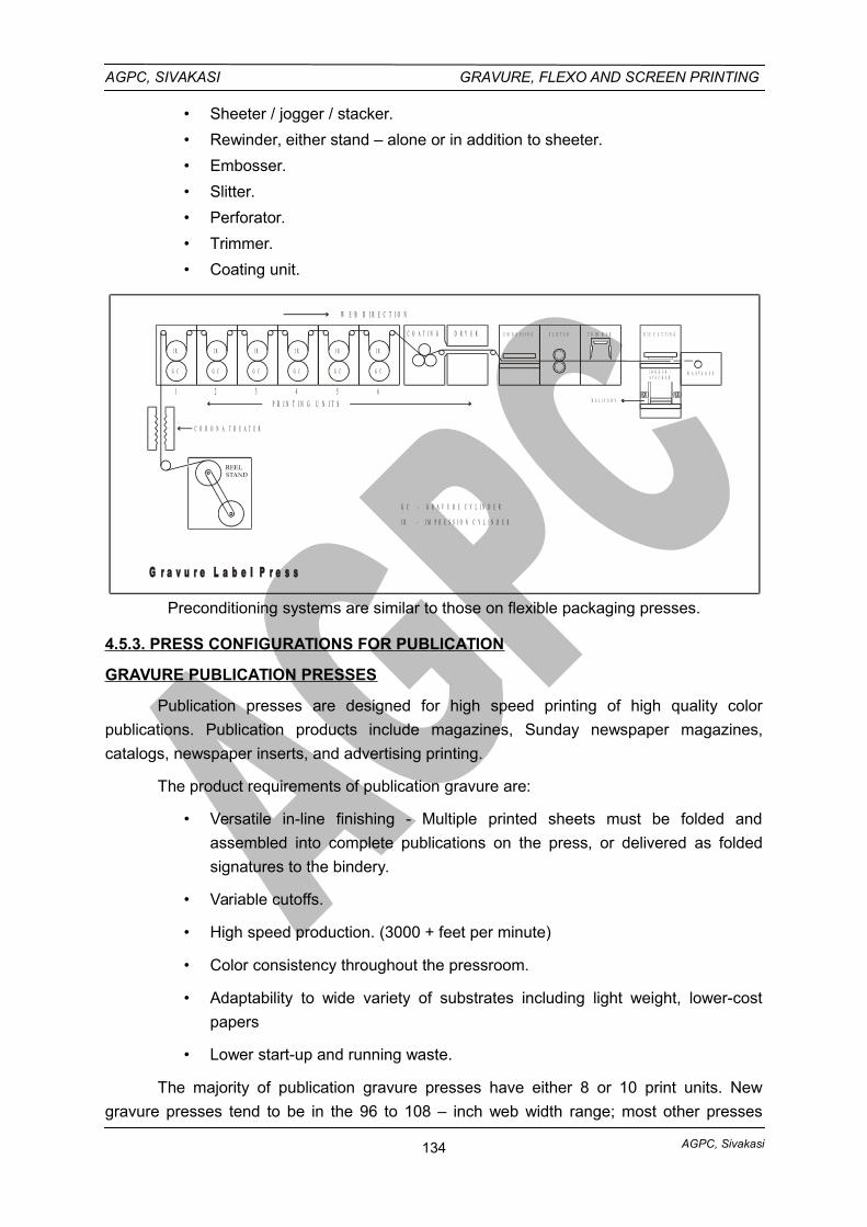
AGPC, Sivakasi
AGPC, SIVAKASI GRAVURE, FLEXO AND SCREEN PRINTING
• Sheeter / jogger / stacker.
• Rewinder, either stand – alone or in addition to sheeter.
• Embosser.
• Slitter.
• Perforator.
• Trimmer.
• Coating unit.
I R I R I R I R
G C G C G C G C
I R
G C
1 2 3 4 5
I R
G C
C O A T I N G D R Y E R
6
C O R O N A T R E A T E R
P R I N T I N G U N I T S
W E B D I R E C T I O N
E M B O S S I N G S L I T T E R D I E C U T T I N G
J O G G E R / S T A C K E R
D E L I V E R Y
W A S T A G E S
G r a v u r e L a b e l P r e s s
T R I M M E R
G C - G R A V U R E C Y L I N D E R
I R - I M P R E S S I O N C Y L I N D E R
Preconditioning systems are similar to those on flexible packaging presses.
4.5.3. PRESS CONFIGURATIONS FOR PUBLICATION
GRAVURE PUBLICATION PRESSES
Publication presses are designed for high speed printing of high quality color
publications. Publication products include magazines, Sunday newspaper magazines,
catalogs, newspaper inserts, and advertising printing.
The product requirements of publication gravure are:
• Versatile in-line finishing - Multiple printed sheets must be folded and
assembled into complete publications on the press, or delivered as folded
signatures to the bindery.
• Variable cutoffs.
• High speed production. (3000 + feet per minute)
• Color consistency throughout the pressroom.
• Adaptability to wide variety of substrates including light weight, lower-cost
papers
• Lower start-up and running waste.
The majority of publication gravure presses have either 8 or 10 print units. New
gravure presses tend to be in the 96 to 108 – inch web width range; most other presses
134
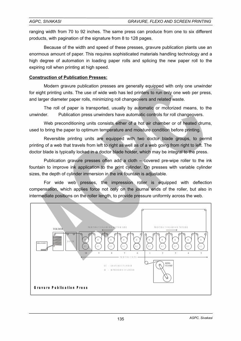
AGPC, Sivakasi
AGPC, SIVAKASI GRAVURE, FLEXO AND SCREEN PRINTING
ranging width from 70 to 92 inches. The same press can produce from one to six different
products, with pagination of the signature from 8 to 128 pages.
Because of the width and speed of these presses, gravure publication plants use an
enormous amount of paper. This requires sophisticated materials handling technology and a
high degree of automation in loading paper rolls and splicing the new paper roll to the
expiring roll when printing at high speed.
Construction of Publication Presses:
Modern gravure publication presses are generally equipped with only one unwinder
for eight printing units. The use of wide web has led printers to run only one web per press,
and larger diameter paper rolls, minimizing roll changeovers and related waste.
The roll of paper is transported, usually by automatic or motorized means, to the
unwinder. Publication press unwinders have automatic controls for roll changeovers.
Web preconditioning units consists either of a hot air chamber or of heated drums,
used to bring the paper to optimum temperature and moisture condition before printing.
Reversible printing units are equipped with two doctor blade groups, to permit
printing of a web that travels from left to right as well as of a web going from right to left. The
doctor blade is typically locked in a doctor blade holder, which may be integral to the press.
Publication gravure presses often add a cloth – covered pre-wipe roller to the ink
fountain to improve ink application to the print cylinder. On presses with variable cylinder
sizes, the depth of cylinder immersion in the ink fountain is adjustable.
For wide web presses, the impression roller is equipped with deflection
compensation, which applies force not only on the journal ends of the roller, but also in
intermediate positions on the roller length, to provide pressure uniformly across the web.
G r a v u r e P u b l i c a t i o n P r e s s
D R Y E R
P R I N T I N G U N I T S
P R I N T I N G 5 C O L O R S O N B O T T O M S I D E P R I N T I N G 5 C O L O R S O N T O P S I D E
I R I R I R I R I R I R I R I R I R
G C G C G C G C G C G C G C G C G C
G C - G R A V U R E C Y L I N D E R
I R - I M P R E S S I O N C Y L I N D E R
I R
G C
135
AGPC, Sivakasi
AGPC, SIVAKASI GRAVURE, FLEXO AND SCREEN PRINTING
Electrostatic Assist systems facilitate transfer of ink from the cylinder engraving to the
web. These systems charge the web, or the rubber, or the side of impression roller, attracting
ink electrostatically to the substrate.
Wide web presses generally equipped with the rehumidifying system (stream bars) to
raise the level of moisture in the paper when shrinkage occurs.
Publication gravure presses are connected to a wide variety of complex slitting,
folding and finishing machines. These in-line operations include:
• Folding
• Stitching
• Auto stacking
• Inserting cards and coupons
• Gluing
• Perforating
• Flexo imprinting
• Letterpress imprinting
• Coating
• Trimming
• Rewinding
GRAVURE FOLDERS
A gravure publication press can be equipped with a variety of folders. The purpose of
the folder is to take single or multiple webs from the printing units, slit them into ribbons,
assemble the ribbons in aligned groups, and pass them through a cut-and-fold mechanism
to produce a folded signature. Folding technology can only be described with a set of unique
terms. Understanding this terminology is essential for anyone buying print, planning layouts,
engraving cylinders, or operating a publication gravure press.
FOLDER TERMINOLOGY
Ribbons are formed by slitting the web as it emerges from the last print unit. These
ribbons continue into folders where they are folded and recombined in various ways.
Angle bars change the orientation of the ribbon by turning it at 90° angle. Singly or in
succession, angle bars are used to reorient web for reverse-direction processing, additional
folding, or to superimpose a group of ribbons to obtain desired pagination.
Cylinder imposition is the way pages are laid out on the publican cylinder. The pages
must match the configuration of the folder in order for every signature to have pages in the
correct sequence and orientation in the finished product. A variety of cylinder layouts can be
used depending on the type of folder, page size, page count, width of the press, and the final
trimmed page size. A one-up imposition refers to a cylinder layout with one set of unique
136
AGPC, Sivakasi
AGPC, SIVAKASI GRAVURE, FLEXO AND SCREEN PRINTING
pages. A two-up cylinder repeats the page layout twice around the circumference of the
cylinder and so on up to six- or eight-around on the newest presses.
TYPES OF FOLDERS
Variable cutoff folders are the most commonly used folders with publication gravure
presses. They enable gravure printers to supply print buyers with a wide variety of product
sizes.
• Upper and lower folders make up the two folder sections of a gravure press.
The upper folder typically slits the web into ribbons, then uses angle bars to
superimpose or gather the ribbons.
• The lower folder cuts and folds the gathered ribbons into signatures. The final
size of the signature can be any desired length and width based on the
dimensions of the printing cylinder.
• Former folders fold a moving web or ribbon in the grain direction of the paper
(parallel to the web path). They are also referred to as long-grain folders.
• Combination folders are capable of a wide variety of folds in both the grain
direction and cross-grain direction. Typically the first fold is accomplished over
a V-shaped former board and the second fold is at a right angle. Additional
folds may be completed before the ribbon leaves the folder.
• Gravure lower folders are often variable in size. They are capable of
producing products with different cutoffs, from different cylinder diameters,
and can accommodate four-, six-, or eight-page layouts around the cylinder.
• Ribbon jaw folders assemble the ribbons then cut and fold them in the cross-
grain direction. The folding action is accomplished by the jaw assembly and
can be either a single or double parallel fold.
• Chopper folders have farmers and are used to produce two-on signatures or
single signatures by alternating the deliveries. The fold is accomplished over
the former in the grain direction.
4.6. SOLVENT BASED INKS, WATER BASED INKS, UV AND EB INKS
Gravure Inks
Gravure inks, like flexographic inks, are liquid inks; that is, they are inks with low
viscosity. They are formulated with pigments, resin varnishes, plasticizers, and solvents.
Many of the pigments used in lithographic inks are also used in gravure inks. The different
types of gravure inks use different types of resins.
The mechanism of gravure ink drying is the same as that of flexographic inks. When
the solvents are evaporated in the dryers, the solid resin remains to hold the pigments and to
bind the ink to the substrate. The inks contain no driers. (Rotogravure news inks require no
heat, as they dry by absorption.)
137
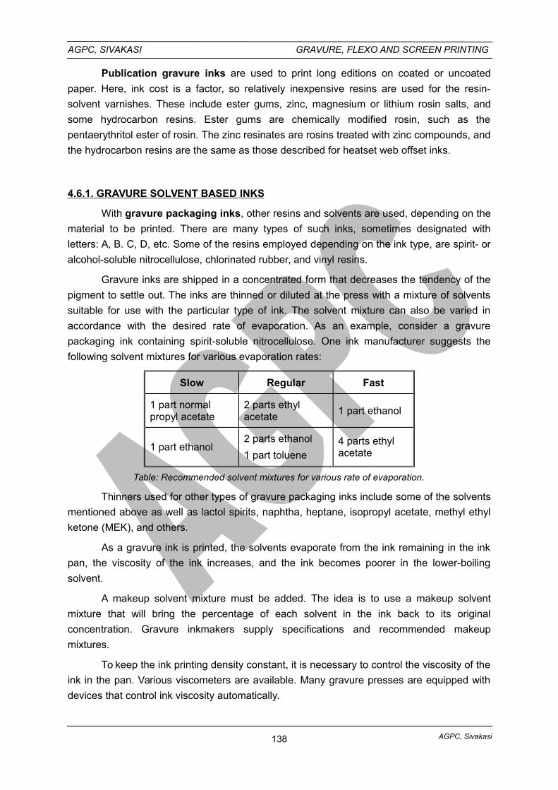
AGPC, Sivakasi
AGPC, SIVAKASI GRAVURE, FLEXO AND SCREEN PRINTING
Publication gravure inks are used to print long editions on coated or uncoated
paper. Here, ink cost is a factor, so relatively inexpensive resins are used for the resin-
solvent varnishes. These include ester gums, zinc, magnesium or lithium rosin salts, and
some hydrocarbon resins. Ester gums are chemically modified rosin, such as the
pentaerythritol ester of rosin. The zinc resinates are rosins treated with zinc compounds, and
the hydrocarbon resins are the same as those described for heatset web offset inks.
4.6.1. GRAVURE SOLVENT BASED INKS
With gravure packaging inks, other resins and solvents are used, depending on the
material to be printed. There are many types of such inks, sometimes designated with
letters: A, B. C, D, etc. Some of the resins employed depending on the ink type, are spirit- or
alcohol-soluble nitrocellulose, chlorinated rubber, and vinyl resins.
Gravure inks are shipped in a concentrated form that decreases the tendency of the
pigment to settle out. The inks are thinned or diluted at the press with a mixture of solvents
suitable for use with the particular type of ink. The solvent mixture can also be varied in
accordance with the desired rate of evaporation. As an example, consider a gravure
packaging ink containing spirit-soluble nitrocellulose. One ink manufacturer suggests the
following solvent mixtures for various evaporation rates:
Slow Regular Fast
1 part normal propyl acetate
2 parts ethyl acetate
1 part ethanol
1 part ethanol2 parts ethanol
1 part toluene4 parts ethyl acetate
Table: Recommended solvent mixtures for various rate of evaporation.
Thinners used for other types of gravure packaging inks include some of the solvents
mentioned above as well as lactol spirits, naphtha, heptane, isopropyl acetate, methyl ethyl
ketone (MEK), and others.
As a gravure ink is printed, the solvents evaporate from the ink remaining in the ink
pan, the viscosity of the ink increases, and the ink becomes poorer in the lower-boiling
solvent.
A makeup solvent mixture must be added. The idea is to use a makeup solvent
mixture that will bring the percentage of each solvent in the ink back to its original
concentration. Gravure inkmakers supply specifications and recommended makeup
mixtures.
To keep the ink printing density constant, it is necessary to control the viscosity of the
ink in the pan. Various viscometers are available. Many gravure presses are equipped with
devices that control ink viscosity automatically.
138
AGPC, Sivakasi
AGPC, SIVAKASI GRAVURE, FLEXO AND SCREEN PRINTING
Drying of Flexo and gravure inks
An advantage of water-based flexo is that and Gravure Inks recovery and disposal of
the solvent is greatly simplified, but most gravure printing and flexo package printing still
require inks containing organic solvents. (Many aqueous inks contain some organic solvents
that must be properly disposed of.)
Organic solvents in the exhaust gas from gravure and flexographic press dryers arecommonly removed by passing the gas through a chamber filled with activated carbon. Thesolvents are removed by adsorption onto the surface of the activated carbon particles. Whenthe carbon becomes saturated with solvent, steam is used to strip the solvents from thecarbon. While this operation is proceeding, the exhaust gas from the dryer is transferred to asecond chamber, also filled with activated carbon. On cooling, the steam and solventsliquefy, separating into two layers. The recovered solvents can be either sold or used on thepress as a dilution solvent.
4.6.2. GRAVURE WATER-BASED INKS
Water-based inks contain little or no volatile solvent and do not constitute anexplosive hazard. However, as relative humidity increases, water evaporates more slowly. Tokeep the humidity from increasing in a dryer, it is necessary to increase the amount ofexhaust air. Increasing the turbulence where the air impinges on the printed web is moreeffective than increasing the temperature when drying water-based inks and coating.Excessive heat can cause extensible substrates to stretch and paper-based substrates toshrink, leading to register and tension control problems.
Water-based ink technology has been around since the 1960s. It is the least costlycompliance option, but today’s technology has many limitations. Water systems require asmuch as five times the amount energy that is required to dry solvent inks. Water inks havebeen successful in packaging and product applications where press speeds have a tendencyto be slower than publication gravure press speeds. Acceptable print quality has beenachieved on coated board, vinyl, aluminum foil, and lightweight papers.
4.6.3. GRAVURE UV CURING INKS
UV-curing coatings and printing inks are typically composed of a vehicle (comprisingmonomers, oligomers, and prepolymers), pigment, and additives, which includephotoinitiator and inhibitor. The formulation is applied to a substrate and cured orpolymerized rapidly by exposure to UV energy. The prepolymers contain chemical groupsthat react and cure with the monomer. The function of the photoinitiator is to absorb theradiation and initiate the free-radical polymerization.
UV-curing inks contain very little VOCs (Volatile Organic Compounds). Solventsfound in conventional inks and coatings are replaced with low viscosity monomers andoligomers that adjust the viscosity and assist in pigment wetting to produce a workable inkvehicle. To produce a homogeneous polymerized ink film requires that the UV radiationpenetrate the full thickness of the film. Except with screen printing, ink and coating films forUV or EB curing are essentially thin films. A generalized formulation for UV ink is presentedin the following table.
139
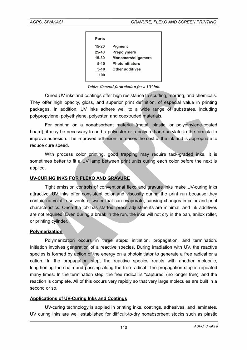
AGPC, Sivakasi
AGPC, SIVAKASI GRAVURE, FLEXO AND SCREEN PRINTING
Parts
15-20
25-40
15-30
5-10
5-10
100
Pigment
Prepolymers
Monomers/oligomers
Photoinitiators
Other additives
Table: General formulation for a UV ink.
Cured UV inks and coatings offer high resistance to scuffing, marring, and chemicals.
They offer high opacity, gloss, and superior print definition, of especial value in printing
packages. In addition, UV inks adhere well to a wide range of substrates, including
polypropylene, polyethylene, polyester, and coextruded materials.
For printing on a nonabsorbent material (metal, plastic, or polyethylene-coated
board), it may be necessary to add a polyester or a polyurethane acrylate to the formula to
improve adhesion. The improved adhesion increases the cost of the ink and is appropriate to
reduce cure speed.
With process color printing, good trapping may require tack-graded inks. It is
sometimes better to fit a UV lamp between print units curing each color before the next is
applied.
UV-CURING INKS FOR FLEXO AND GRAVURE
Tight emission controls of conventional flexo and gravure inks make UV-curing inks
attractive. UV inks offer consistent color and viscosity during the print run because they
contain no volatile solvents or water that can evaporate, causing changes in color and print
characteristics. Once the job has started, press adjustments are minimal, and ink additives
are not required. Even during a break in the run, the inks will not dry in the pan, anilox roller,
or printing cylinder.
Polymerization
Polymerization occurs in three steps: initiation, propagation, and termination.
Initiation involves generation of a reactive species. During irradiation with UV. the reactive
species is formed by action of the energy on a photoinitiator to generate a free radical or a
cation. In the propagation step, the reactive species reacts with another molecule,
lengthening the chain and passing along the free radical. The propagation step is repeated
many times. In the termination step, the free radical is “captured’ (no longer free), and the
reaction is complete. All of this occurs very rapidly so that very large molecules are built in a
second or so.
Applications of UV-Curing Inks and Coatings
UV-curing technology is applied in printing inks, coatings, adhesives, and laminates.
UV curing inks are well established for difficult-to-dry nonabsorbent stocks such as plastic
140
AGPC, Sivakasi
AGPC, SIVAKASI GRAVURE, FLEXO AND SCREEN PRINTING
packaging and wet-on-dry printing. Instantaneous drying allows colors to be dried at press
speed between printing units, thus eliminating the problems associated with wet-on-wet web
or sheetfed printing.
In publication and commercial printing, UV curing is used on posters, magazine
covers, book covers, and a broad range of products. In packaging, UV curing is used for
printing and coating of paper, paperboard, film, and ceramics, producing folding cartons,
labels, and record jackets among many products. In converting industries, it is used in many
applications such as laminates, adhesives, and clear and pigmented coatings.
OTHER UV-CURING SYSTEMS
i. Free-radical-curing systems
Photoinitiators that generate free radicals under UV illumination are used with
materials such as acrylic or methacrylic monomers or prepolymers.
Unsaturated, high-boiling acrylic or methacrylic monomers, oligomers, cross-inking
agents, and low-molecular-weight polymers comprise the fluid, low-viscosity, light-curing
coating system used in UV-curing inks and coatings initiated with free radicals.
Free-radical polymerization and cross-inking processes are inhibited by oxygen,
which reacts with free radicals and interferes with both the initiation and propagation steps of
the polymerization reaction. Coating surfaces are appropriate to remain tacky or “oxygen-
inhibited.” A blanket of nitrogen gas is used to remove air and prevent this inhibition. Good
design of the equipment keeps nitrogen consumption to a minimum. Tacky surfaces can be
overcome by a post cure or bake cycle.
The inhibition of cure is also overcome by incorporating amines into the formulation.
For UV-curing inks, a high concentration of free radicals at the surface overwhelms the
negative effects of oxygen.
The degree of cure, which is not easily measured, is affected by the following:
• Concentration of the photoinitiator
• Type of photoinitiator
• Radiation wavelength and intensity
• Film thickness
• Effect of oxygen
• Additives to the ink or coating
• Nature of the substrate and back scattering or transmission of UV light
ii. Cationic-curing systems
Most pigments absorb UV radiation, so that only very thin films or clear coatings canbe cured by UV-free-radical chemistry. Under UV radiation, cationic initiators form cations,reactive acidic materials that react with cycloaliphatic epoxy compounds and vinyl ethers in
141
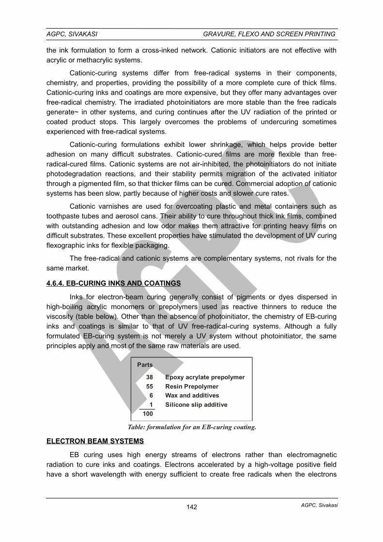
AGPC, Sivakasi
AGPC, SIVAKASI GRAVURE, FLEXO AND SCREEN PRINTING
the ink formulation to form a cross-inked network. Cationic initiators are not effective withacrylic or methacrylic systems.
Cationic-curing systems differ from free-radical systems in their components,chemistry, and properties, providing the possibility of a more complete cure of thick films.Cationic-curing inks and coatings are more expensive, but they offer many advantages overfree-radical chemistry. The irradiated photoinitiators are more stable than the free radicalsgenerate~ in other systems, and curing continues after the UV radiation of the printed orcoated product stops. This largely overcomes the problems of undercuring sometimesexperienced with free-radical systems.
Cationic-curing formulations exhibit lower shrinkage, which helps provide betteradhesion on many difficult substrates. Cationic-cured films are more flexible than free-radical-cured films. Cationic systems are not air-inhibited, the photoinitiators do not initiatephotodegradation reactions, and their stability permits migration of the activated initiatorthrough a pigmented film, so that thicker films can be cured. Commercial adoption of cationicsystems has been slow, partly because of higher costs and slower cure rates.
Cationic varnishes are used for overcoating plastic and metal containers such astoothpaste tubes and aerosol cans. Their ability to cure throughout thick ink films, combinedwith outstanding adhesion and low odor makes them attractive for printing heavy films ondifficult substrates. These excellent properties have stimulated the development of UV curingflexographic inks for flexible packaging.
The free-radical and cationic systems are complementary systems, not rivals for thesame market.
4.6.4. EB-CURING INKS AND COATINGS
Inks for electron-beam curing generally consist of pigments or dyes dispersed inhigh-boiling acrylic monomers or prepolymers used as reactive thinners to reduce theviscosity (table below). Other than the absence of photoinitiator, the chemistry of EB-curinginks and coatings is similar to that of UV free-radical-curing systems. Although a fullyformulated EB-curing system is not merely a UV system without photoinitiator, the sameprinciples apply and most of the same raw materials are used.
Parts
38
55
6
1
100
Epoxy acrylate prepolymer
Resin Prepolymer
Wax and additives
Silicone slip additive
Table: formulation for an EB-curing coating.
ELECTRON BEAM SYSTEMS
EB curing uses high energy streams of electrons rather than electromagneticradiation to cure inks and coatings. Electrons accelerated by a high-voltage positive fieldhave a short wavelength with energy sufficient to create free radicals when the electrons
142
AGPC, Sivakasi
AGPC, SIVAKASI GRAVURE, FLEXO AND SCREEN PRINTING
collide with monomers such as acrylates and methacrylates. Curing is instantaneous even inthick films, and no postcuring is required.
The 5-10% of UV formulation that comprises the initiator package is replaced byprepolymer or monomer. This offers several advantages. The EB energy easily penetratesthick films, and through-cure is no problem.
Replacing the photoinitiator with monomer or prepolymer enhances the mechanicalproperties of the cured film and reduces the presence of extractable materials. Eliminatingthe expensive photoinitiator reduces the cost of the ink and reduces risk of odor orcontamination with toxic materials. Eliminating the possibility of odor and taint from the photoinitiator is especially important with food packaging.
It should be possible, at a sufficiently high voltage, to generate electrons with enoughenergy to penetrate a sheet and cure ink or coating on both sides at once, but suitableequipment is apparently unavailable.
Equipment for Applying and Curing EB Inks and Coatings
Electron beams are generated by applying an accelerating voltage to a cathode.They have an energy of 120-300 KeV. Two types of EB accelerators are used in printing andconverting plants. In the scanner type, electrons, generated from a point cathode in a highvacuum, are spread out into a curtain by a beam splitter. In the linear cathode generator,electrons are emitted from a suspended wire cathode. The electrons are not focused but areemitted over the total length of the wire.
The electrons leave the beam housing through a very thin metal foil. When theseelectron beams strike suitable monomers, they initiate polymerization. It must be performedin the absence of oxygen by using a vacuum or a nitrogen atmosphere.
The disadvantages of EB curing are the high cost of the installation, the need tooperate in an inert atmosphere to minimize the inhibiting effects of oxygen, and the need toshield the equipment to protect operators from X rays generated when electron beams strikemetal.
These problems are reduced with the latest designs that incorporate developingtechnology.
143
AGPC, Sivakasi
AGPC, SIVAKASI GRAVURE, FLEXO AND SCREEN PRINTING
UNIT: IV – GRAVURE PRINTING
PART - A - 1 Mark Questions
1. Name the various layers of imaged copper cylinder.
i. Base steel core layer
ii. Nickel layer
iii. Base copper layer
iv. Engraving copper layer
v. Chromium layer
2. What are the different methods of copper plating the cylinder?
i. The thin copper layer method (approximately 80 mm of copper)
ii. The Ballard skin method (removable copper skin of 80 to 100 mm)
iii. The heavy copper plating method (approximately 320 mm of copper)
3. How do gravure inks dry?
Gravure inks dry by evaporation of solvents. Gravure inks are low viscous inks. This
low viscosity is achieved by using a high proportion of solvent. To dry the printed ink, the
solvent must be evaporated by using high velocity air drying after leaving the printing nip.
4. What are doctor blade streaks?
One of the most common print defects unique to gravure printing is the doctor blade
streak. This streaks occur because a foreign particle (dirt) will get lodged under the doctor
blade, causing a streak. Proper doctor blade oscillation can minimize this problem and
reduce cylinder wear.
5. What are solvents?
Solvents serves two purposes – to dissolve the resin and to adjust viscosity of ink.
Solvents are liquids that dissolve a solid. In an ink, the evaporation of solvent leave the
solids behind as an ink film on the substrate.
6. What do you mean by solvent based inks?
Gravure printing uses solvent based inks which are shipped in a concentrated form.
These inks are thinned or diluted with a mixture of solvents suitable for use with particular
type of ink. Gravure inks dry by evaporation of solvents.
7. State the different types of doctor blades used for gravure.
Types of Doctor Blades based on designs:
• Conventional doctor blades
• MDC / Ringier doctor blades
• Counter face doctor blades
• Rounded doctor blades
8. State the doctor blade-wiping angle recommended for gravure printing.
144
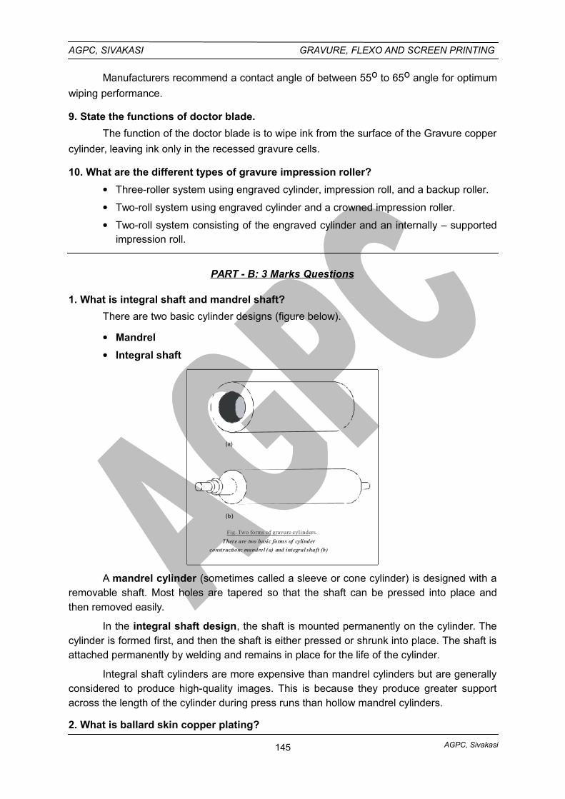
AGPC, Sivakasi
AGPC, SIVAKASI GRAVURE, FLEXO AND SCREEN PRINTING
Manufacturers recommend a contact angle of between 55o to 65o angle for optimum
wiping performance.
9. State the functions of doctor blade.
The function of the doctor blade is to wipe ink from the surface of the Gravure copper
cylinder, leaving ink only in the recessed gravure cells.
10. What are the different types of gravure impression roller?
Three-roller system using engraved cylinder, impression roll, and a backup roller.
Two-roll system using engraved cylinder and a crowned impression roller.
Two-roll system consisting of the engraved cylinder and an internally – supportedimpression roll.
PART - B: 3 Marks Questions
1. What is integral shaft and mandrel shaft?
There are two basic cylinder designs (figure below).
Mandrel
Integral shaft
(a)
(b)
Fig. Two forms of gravure cylinders.
There are two basic forms of cylinder
construction: mandrel (a) and integral shaft (b)
A mandrel cylinder (sometimes called a sleeve or cone cylinder) is designed with aremovable shaft. Most holes are tapered so that the shaft can be pressed into place andthen removed easily.
In the integral shaft design, the shaft is mounted permanently on the cylinder. Thecylinder is formed first, and then the shaft is either pressed or shrunk into place. The shaft isattached permanently by welding and remains in place for the life of the cylinder.
Integral shaft cylinders are more expensive than mandrel cylinders but are generallyconsidered to produce high-quality images. This is because they produce greater supportacross the length of the cylinder during press runs than hollow mandrel cylinders.
2. What is ballard skin copper plating?
145
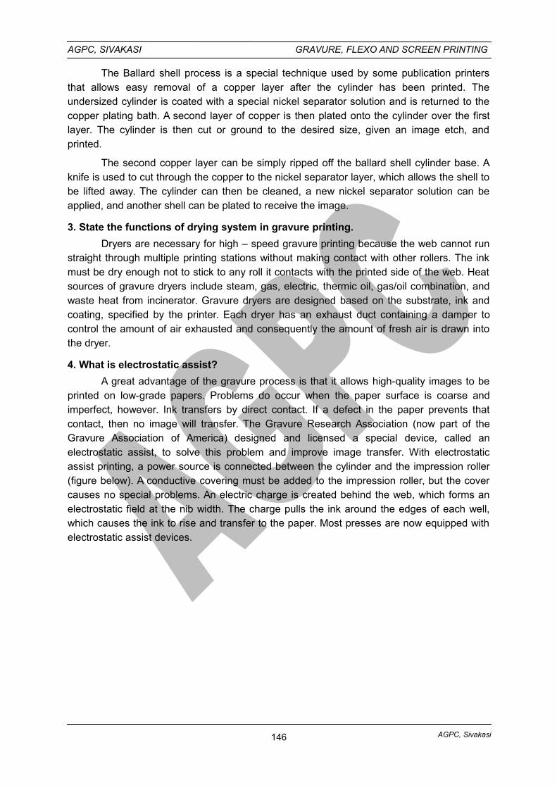
AGPC, Sivakasi
AGPC, SIVAKASI GRAVURE, FLEXO AND SCREEN PRINTING
The Ballard shell process is a special technique used by some publication printersthat allows easy removal of a copper layer after the cylinder has been printed. Theundersized cylinder is coated with a special nickel separator solution and is returned to thecopper plating bath. A second layer of copper is then plated onto the cylinder over the firstlayer. The cylinder is then cut or ground to the desired size, given an image etch, andprinted.
The second copper layer can be simply ripped off the ballard shell cylinder base. Aknife is used to cut through the copper to the nickel separator layer, which allows the shell tobe lifted away. The cylinder can then be cleaned, a new nickel separator solution can beapplied, and another shell can be plated to receive the image.
3. State the functions of drying system in gravure printing.
Dryers are necessary for high – speed gravure printing because the web cannot runstraight through multiple printing stations without making contact with other rollers. The inkmust be dry enough not to stick to any roll it contacts with the printed side of the web. Heatsources of gravure dryers include steam, gas, electric, thermic oil, gas/oil combination, andwaste heat from incinerator. Gravure dryers are designed based on the substrate, ink andcoating, specified by the printer. Each dryer has an exhaust duct containing a damper tocontrol the amount of air exhausted and consequently the amount of fresh air is drawn intothe dryer.
4. What is electrostatic assist?
A great advantage of the gravure process is that it allows high-quality images to beprinted on low-grade papers. Problems do occur when the paper surface is coarse andimperfect, however. Ink transfers by direct contact. If a defect in the paper prevents thatcontact, then no image will transfer. The Gravure Research Association (now part of theGravure Association of America) designed and licensed a special device, called anelectrostatic assist, to solve this problem and improve image transfer. With electrostaticassist printing, a power source is connected between the cylinder and the impression roller(figure below). A conductive covering must be added to the impression roller, but the covercauses no special problems. An electric charge is created behind the web, which forms anelectrostatic field at the nib width. The charge pulls the ink around the edges of each well,which causes the ink to rise and transfer to the paper. Most presses are now equipped withelectrostatic assist devices.
146
AGPC, Sivakasi
AGPC, SIVAKASI GRAVURE, FLEXO AND SCREEN PRINTING
Gravurecylinder
Chargedimpression roller
Paper
Power
PowerTransfer roller
Fig. Diagram of electrostatic assist printing.Electrostatic assist printing charges the impression roller
and the gravure cylinder so that the ink lifts electrostatically
from the cylinder to the paper.
5. What is a solvent recovery system?
Solvent recovery system removes solvent fumes from- the dryer exhaust air and
collects the solvent for reuse. Solvent recovery systems are excellent for multiple press
operations where the solvents be selected for easy recovery and reuse. Publication gravure
liters use solvent recovery systems almost exclusively. The recovered solvent costs only a
fraction of the cost of new solvent and helps to offset the cost of the solvent recovery
equipment.
Solvent recovery for packaging and product gravure operations more difficult
because of the variety of solvents used in the ink and coating formulations. Recovered
solvent requires further treatment before it can be reused. This often increases the cost
above the cost of new solvent. Solvent recovery is very rarely cost effective for packaging
and product printers running multiple solvents.
6. What are the factors that determine selection of solvents for gravure inks.
Solvents are particularly important in gravure – they ensure the low viscosity of the
ink and they also change the pigment concentration / optical ink density. The following
factors are important for selecting solvents:
• Boiling point
• Evaporation number
• Flash point
• Explosion limit
• Odour
• Work safety and
• Ecological compatibility.
Completely different solvents have to be used for Publication gravure and Gravure
package printing. This is mainly because of the very varied requirements of individual
packaging.
147
AGPC, Sivakasi
AGPC, SIVAKASI GRAVURE, FLEXO AND SCREEN PRINTING
7. State the advantages of water based gravure inks.
Water based inks are designed to be reduced with water and the press clean
up is done with water. Most water inks are emulsions rather than solutions asin the alcohol type ink.
Water based inks are almost always used on absorbent surfaces such as
paper. Water is the usual solvent.
The main advantage of water – based inks is that they do not present a fire
hazard since solvents other than water are not necessarily needed. Water isvery convenient for use and economically it is also cheaper.
Water based inks have been successful in packaging and product
applications where press speeds have a tendency to be slower thanpublication gravure press speeds. Acceptable print quality has been achievedon coated board, vinyl, aluminium foil, and light weight boards.
8. State the functions of gravure impression roller.
The functions of the impression roll are to force contact between the web and the
engraved cylinder, to create the necessary web tension between printing units, and to propel
the web through the press. The impression roll brings the substrate in contact with the
engraved cylinder resulting in proper ink transfer. It is a friction driven rubber covered metal
cylinder. It helps to propel the web through the press and set the web tension pattern
between press units.
PART - C: 10 Marks Questions
1. Describe the process sequence for the preparation of copper cylinder.
2. Explain the various methods of copper plating the gravure cylinder.
3. Explain the gravure drying systems with diagrams.
4. Describe the working principles and functioning of gravure solvent recovery system.
5. Explain the structure and mechanisms of gravure doctor blade.
6. Explain the structure and mechanisms of gravure impression roller.
7. Describe the construction of a gravure packaging press with diagrams.
8. Explain the main sections of a gravure label press with diagrams.
9. Describe the construction of a gravure publication press with necessary sketches.
10. Explain the characteristics of solvent-based inks and water-based inks used for gravure printing.
11. Write notes on a) Ultraviolet inks b) Electron beam inks used for gravure printing.
12. Write short notes on (a) Label press (b) Solvent based ink (c) Drying chambers.
GLOSSARY
Balance
148
AGPC, Sivakasi
AGPC, SIVAKASI GRAVURE, FLEXO AND SCREEN PRINTING
Even distribution of the mass or a cylinder or roll about its axis.
Carbon Absorber
An add-on device using activated carbon to absorb volatile organic compounds from
a gas stream.
Chalking
Occurs when the pigment in the printed ink is not properly bound to the paper,
becoming powdery and easily rubbed off.
Combination Folder
A folding unit which incorporates the characteristics of both a knife and buckle folder.
Consistency
The general body characteristics of an ink, (e.g., viscosity, uniformity) used to
describe the rheological property of an ink – i.e., thick, thin or buttery.
Doctor Blade
A thin, flexible blade mounted parallel to and adjustable against an engraved roll, forthe purpose of scraping off excess material.
Dynamic Balance
The state when rotating masses are in equilibrium.
Electron Beam (EB) Curing
Converting a wet coating or printing-ink film to a solid film by using an electron beam.Electrons are small, negatively charged particles that penetrate the material; thus using EBfor curing pigments is more efficient.
Engraved Roll
A roll having a mechanically or laser engraved surface. See also Anilox Roll, DesignRoll.
Engraving
A general term normally applied to any pattern which has been cut in or incised in asurface by hand, mechanical, laser or chemical etching processes.
Etch
To dissolve the nonprinting areas of a metal plate by the action of an acid, as in theengravings used to mold the matrix.
Eye Mark or Eye Spot
A small, rectangular printed area usually located near the edge of a web or design, toactivate an automatic electronic position regulator for controlling register of the printeddesign with subsequent equipment or operations.
Face Printing
Printing on the outer surface of a transparent film, contrary to printing on the back(reverse) of the film.
Gravurescope
149
AGPC, Sivakasi
AGPC, SIVAKASI GRAVURE, FLEXO AND SCREEN PRINTING
A type of microscope designed for inspecting and measuring the engraved cells on
an anilox roll or a gravure cylinder. Measures both vertically for depth and horizontally for
width.
Heat Seal
A method of uniting two or more surfaces by fusion, either of the coatings or of thebase materials, under controlled conditions of temperature, pressure and time (dwell).
Incineration
The destruction of solid, liquid or gaseous wastes by controlled burning at hightemperatures.
Mandrel
A shaft upon which cylinders, or other devices, are mounted or affixed.
Photoengraving
A metal plate prepared photochemically, from which the matrix or rubber mold isreproduced.
Pigment
An insoluble coloring material dispersed in a liquid vehicle to impart color to inks,
paints and plastics. See also dyes.
Plate Cylinder
The press cylinder on which the printing plates are mounted. There are two types.
Integral, the shaft is a permanent part of the body. Demountable, the shaft is removable to
receive a multiple of bodies of varying diameters and, in some cases, face widths.
Score
To make an impression or a partial cut in a material to facilitate its bending, creasing,
folding or tearing.
Slitter
A machine to cut roll stock in the long direction. Three types are widely used: razor
blade slitter, shear slitter and score cutter.
Solvent
A substance that is liquid at standard conditions and is used to dissolve or dilute
another substance. This term includes, but is not limited to, organic materials used as
dissolvers, viscosity reducers, degreasers or cleaning agents. Water is considered the
universal solvent.
Turning Bars
An arrangement of stationary bars on a flexo press which guide the web in such a
manner that it is turned front to back, and will be printed on the reverse side by the printing
units located subsequent to the turning bars.
Water-based Ink
An alternative to solvent-based inks, these contain a vehicle whose binder is water-
soluable or water dispersible.
150
AGPC, Sivakasi
AGPC, SIVAKASI GRAVURE, FLEXO AND SCREEN PRINTING
Web Guide
The device which keeps the web traveling in a straight or true path through the press.
151
AGPC, Sivakasi
AGPC, SIVAKASI GRAVURE, FLEXO AND SCREEN PRINTING
UNIT - V – SCREEN PRINTING
5.1. MESH, SQUEEGEE SELECTION
5.1.1. MESH (WOVEN SCREEN PRINTING FABRIC)
The woven screen printing fabric serves two primary functions: the fabric supportsthe stencil system, and the fabric’s mesh permits ink to flow through the image area. Themesh plays a dominant role in metering the amount of ink that will flow onto the substrate.
The earliest fabrics used for screen printing included silk, hence the former name forthe process: silk screen printing. Today, monofilament polyester is the most common screenfabric, followed by multifilament polyester, nylon, wire mesh, and silk, in that order.
Nylon, for example, is often used for container printing where the fabric must conformto unusual surfaces during printing and then it return to its original shape afterwards.Metalized polyester and stainless steel are commonly used when maximum stability isrequired and static is a by-product of the print action. The mesh may be grounded to relieveerratic print edges where the ink follows a conductive path onto the substrate.
MATERIALS USED FOR SCREEN P RINTING FABRICS
The two basic categories of fabrics commonly used in screen printing aremultifilament and monofilament.
MULTIFILAMENT FABRICS
Multifilament Fabric is made up of many fine strands twisted together to form asingle thread. The multifilament threads are woven together to form the screen mesh.Multifilament fabric is gauged by the double-X system. Used for many years for measuringsilk bolt cloth, but not based on any real measurement, the double X is preceded by anumber denoting mesh count. The higher the number the finer the mesh and the smaller themesh openings. Multifilament fabrics commonly range from 6XX to 25XX. Most multifilamentfabrics used for screen printing applications are either silk or polyester.
i. Silk
Silk, the original mesh fabric used in screen printing, is the strongest of all naturalfibers. Each silk filament varies in width, causing irregular mesh apertures that can distortthe printed image. Since silk is a multifilament mesh, it cannot be woven as fine asmonofilaments. Therefore silk is only suitable for work where accurate registration and finedetails are not required. Because silk has irregularities and a rough surface structure, inkparticles tend to become lodged between the twisted strands, making silk difficult to clean.For these and other reasons, long-time users of silk have turned to multifilament polyester.
ii. P olyester
Multifilament Polyester is less expensive than domestic and imported silk. It hasmore uniform mesh apertures and doesn’t expand as much as silk during printing. Asopposed to silk, polyester is not affected by strong chemicals used in cleaning or reclaimingthe screen. The disadvantage of multifilament polyester is that the fibers tend to flattenconsiderably more than monofilament fibers at thread intersections. This results in a closingof mesh apertures that shows up in printing as saw-toothed image edges.
151
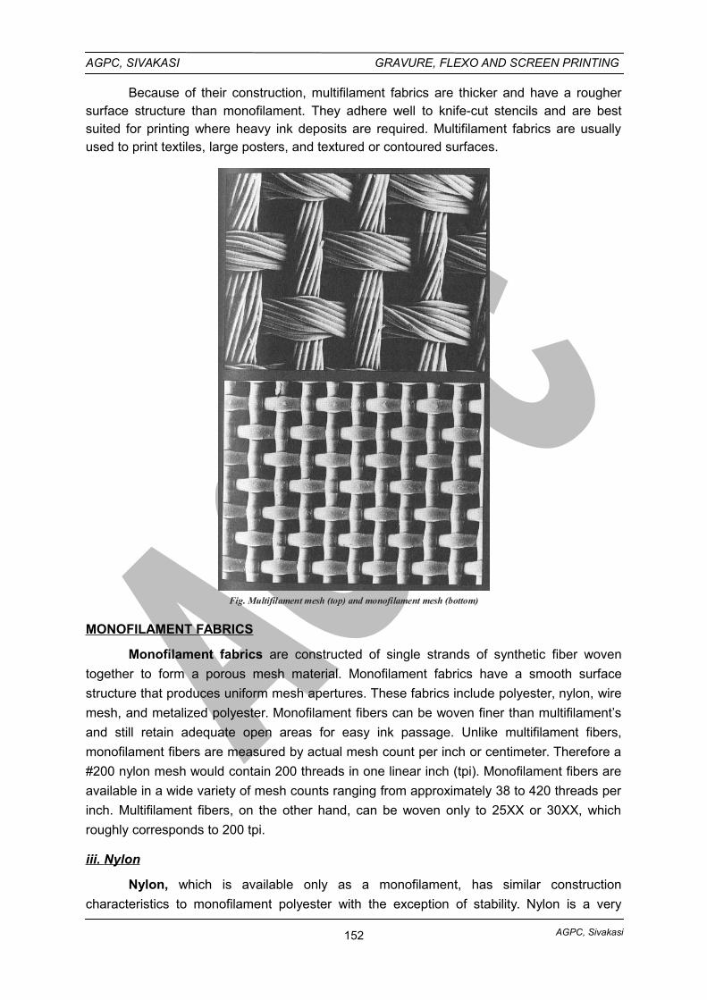
AGPC, Sivakasi
AGPC, SIVAKASI GRAVURE, FLEXO AND SCREEN PRINTING
Because of their construction, multifilament fabrics are thicker and have a roughersurface structure than monofilament. They adhere well to knife-cut stencils and are bestsuited for printing where heavy ink deposits are required. Multifilament fabrics are usuallyused to print textiles, large posters, and textured or contoured surfaces.
Fig. Multifilament mesh (top) and monofilament mesh (bottom)
MONOFILAMENT FABRICS
Monofilament fabrics are constructed of single strands of synthetic fiber woven
together to form a porous mesh material. Monofilament fabrics have a smooth surface
structure that produces uniform mesh apertures. These fabrics include polyester, nylon, wire
mesh, and metalized polyester. Monofilament fibers can be woven finer than multifilament’s
and still retain adequate open areas for easy ink passage. Unlike multifilament fibers,
monofilament fibers are measured by actual mesh count per inch or centimeter. Therefore a
#200 nylon mesh would contain 200 threads in one linear inch (tpi). Monofilament fibers are
available in a wide variety of mesh counts ranging from approximately 38 to 420 threads per
inch. Multifilament fibers, on the other hand, can be woven only to 25XX or 30XX, which
roughly corresponds to 200 tpi.
iii. Nylon
Nylon, which is available only as a monofilament, has similar construction
characteristics to monofilament polyester with the exception of stability. Nylon is a very
152
AGPC, Sivakasi
AGPC, SIVAKASI GRAVURE, FLEXO AND SCREEN PRINTING
elastic fiber, making it a favorite for printing irregularly shaped or contoured surfaces.
However, elasticity is an undesirable characteristic wherever critic registration is a necessity.
Nylon is also affected by temperature and humidity, making multicolor registration very
difficult at times.
iv. Wire Mesh
Wire mesh, commonly called wire cloth, is commonly used with abrasive inks, such
as those used to print on ceramics, or wherever extreme sharpness, close tolerance, and
thick ink film deposits are required, as in printed circuit boards. Wire mesh is extremely
stable and is available in very fine mesh counts up to approximately 635 tpi. Reclaiming
these screens, the process of stripping the stencil from a screen so it can be reused, is
comparatively easier than with nylon or polyester, and they can be reused many times. Wire
mesh, however has a total lack of memory, i.e., it will not spring back if dented or grooved,
as will nylon, polyester, or silk.
v. Metallized Mesh
Metallized mesh is a relatively new fabric developed for screen printing. It is
composed of a monofilament synthetic fiber, either polyester or nylon, coated by an
extremely thin layer of metal. In combining these elements, metalized polyester or nylon
mesh has the advantages of both wire and monofilament synthetics. It will not dent or
deform like wire nor does it repel indirect stencils without pretreatment as does polyester or
nylon. The metal coating makes cleaning the screen easier than that of synthetic fibers.
Metalized mesh has excellent dimensional stability and can be used for very long runs where
close tolerances and exact register are a necessity.
SELECTING A MESH (SCREEN PRINTING FABRIC)
Selecting a screen fabric is one of the most important decisions a screen printer must
make. The type of material along with mesh count, substrate absorptivity and shape, nature
of ink, type of stencil, squeegee composition and blade angle, the design characteristics,
and the thickness of the printed ink deposit required are all factors considered prior to actual
printing.
The following are general rules of thumb that can be used in deciding which screen
fabric will best suit the printer’s needs.
• Monofilaments are more abrasion resistant, available in finer mesh counts,
and offer easier cleaning and ink passage than multifilaments. The screen
surface must be mechanically and chemically pretreated to allow indirect
stencils to adhere.
• Multifilaments have a thicker and rougher surface than monofilaments and
offer excellent adherence for knife-cut stencils along with heavy deposits of
ink.
153
AGPC, Sivakasi
AGPC, SIVAKASI GRAVURE, FLEXO AND SCREEN PRINTING
• The open area of a mesh is the area between threads; it allows the passage
of ink. The larger the percentage of open mesh area, the greater the amount
of ink deposited during printing.
• Each mesh opening should be at least three times larger than the average
grain size in the pigment of the ink otherwise a screen will clog during
printing.
• Mesh count varies according to thread diameter the smaller the thread
diameter, the finer the mesh.
• Thread diameter is one factor that determines the thickness of the printed ink
film—the thinner the thread, the thinner the printed ink deposit; conversely,
the thicker the thread, the thicker the ink deposit.
• The finer the detail in the design, the finer the mesh needed to reproduce it.
For halftone and full-color printing, a mesh least three times finer than the
screen ruling of the halftone is needed.
5.1.2. SQUEEGEE SELECTION
THE SQUEEGEE
The squeegee is a rubber or plastic blade, attached to a handle, use to force ink
through the open areas of the stencil and mesh to the substrate. The functions of the
squeegee are to control the spread of ink across the screen during printing to bring the ink-
filled screen into contact with the substrate and-to a certain extent-to determine the
thickness of the printed ink film.
Ink is applied to one end of the screen. The squeegee blade should be slightly larger
than the image area to ensure even ink coverage. The Width of the blade is a function of the
image size. As much distance as possible between the blade and edges of the frame is
recommended, but the squeegee needs to exceed the width of the image area by a inch or
two on each side of the image width. The squeegee controls the spread of ink because it is
used to draw the ink across the screen, causing it to penetrate the open area of the image
carrier. This can be done either manually or by machine, depending upon the type of work,
length or run, or availability of equipment.
The second function of the squeegee is to bring the ink-filled screen into contact withthe substrate during off-contact printing. Screen printing can be done either on-contact or off-contact with the substrate.
During off-contact printing, the screen is lowered to a point slightly above thesubstrate. The squeegee is drawn across the screen with downward pressure. Because ofthe elasticity of the screen, the pressure of the squeegee forces the stencil into contact withthe substrate. As the squeegee passes, the stencil immediately separates or snaps off fromthe wet print. Off-contact printing generally produces sharper prints by eliminating imagespread and smudging. The use of a vacuum base will prevent a flat, lightweight substratefrom sticking to the underside of the screen when it is raised. In manual printing, off-contactcan be established by taping cardboard shims to the underside corners of the frame.
154
AGPC, Sivakasi
AGPC, SIVAKASI GRAVURE, FLEXO AND SCREEN PRINTING
Automated Screen printing presses employ adjustable devices that control the amount of off-contact.
On-contact printing is done with the underside of the screen in full contact with thesubstrate. On-contact is used when heavy ink deposits are required. However, since imagesharpness will decrease considerably, it is used only on substrates for which imagesharpness is of little importance, e.g., textiles such as terry cloth or towels.
SQUEEGEEE SELECTION
I. Shapes of Squeegee blades
Squeegee blades are available in a variety of shapes. Different shaped blades areused to print on different substrates. The simplest and most common profile used in screenprinting is a square 90° angle. The general shapes and uses for each blade angle are foundin the following table.
Shapes of Squeegee Blades
A. Square edge - For printing on flat objects
B. Square edge with rounded corners
-For extra-heavy deposits. For printing light color on dark backgrounds or printing with fluoresent inks.
C. Single-sided bevel edge - For use mostly by glass or nameplate printers.
D. Double-sided bevel edge - For direct printing on uneven surfaces; bottles.
E. rounded edge -For printing heavy deposits of ink on containers and ceramics.
F. Double bevel edge - For printing textile designs.
G. Diamond edge - For container printing and applications
II. Squeegee Hardness
Squeegee blades are rated according to hardness, which is measured in values ofdurometer. Generally, soft, low-durometer, dull squeegees deposit more ink; while hard,high-durometer, sharp squeegees deposit less ink.
Hardness Categories of Squeegee Blades
i. Extra
ii. Soft
iii. Medium
iv. Hard
45 - 50 durometer
50 - 60 durometer
60 - 70 durometer
70 - 90 durometer
III. Squeegee Materials
Squeegee blades are more commonly composed of synthetic materials rather than
rubber, especially for printing runs over 200. Although rubber blades are easy to use, they
tend to lose their shape and edge quickly. The introduction of plastic compounds, such as
polyvinyl and polyurethane, has solved this problem. Synthetics tend to keep the desired
155
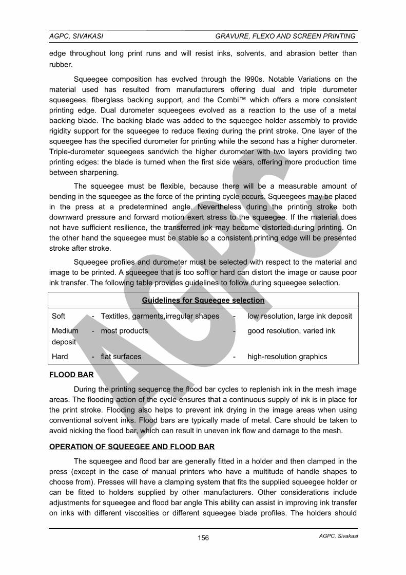
AGPC, Sivakasi
AGPC, SIVAKASI GRAVURE, FLEXO AND SCREEN PRINTING
edge throughout long print runs and will resist inks, solvents, and abrasion better than
rubber.
Squeegee composition has evolved through the l990s. Notable Variations on thematerial used has resulted from manufacturers offering dual and triple durometersqueegees, fiberglass backing support, and the Combi™ which offers a more consistentprinting edge. Dual durometer squeegees evolved as a reaction to the use of a metalbacking blade. The backing blade was added to the squeegee holder assembly to providerigidity support for the squeegee to reduce flexing during the print stroke. One layer of thesqueegee has the specified durometer for printing while the second has a higher durometer.Triple-durometer squeegees sandwich the higher durometer with two layers providing twoprinting edges: the blade is turned when the first side wears, offering more production timebetween sharpening.
The squeegee must be flexible, because there will be a measurable amount ofbending in the squeegee as the force of the printing cycle occurs. Squeegees may be placedin the press at a predetermined angle. Nevertheless during the printing stroke bothdownward pressure and forward motion exert stress to the squeegee. If the material doesnot have sufficient resilience, the transferred ink may become distorted during printing. Onthe other hand the squeegee must be stable so a consistent printing edge will be presentedstroke after stroke.
Squeegee profiles and durometer must be selected with respect to the material andimage to be printed. A squeegee that is too soft or hard can distort the image or cause poorink transfer. The following table provides guidelines to follow during squeegee selection.
Guidelines for Squeegee selection
Soft - Textitles, garments,irregular shapes - low resolution, large ink deposit
Medium - most products - good resolution, varied ink
deposit
Hard - flat surfaces - high-resolution graphics
FLOOD BAR
During the printing sequence the flood bar cycles to replenish ink in the mesh imageareas. The flooding action of the cycle ensures that a continuous supply of ink is in place forthe print stroke. Flooding also helps to prevent ink drying in the image areas when usingconventional solvent inks. Flood bars are typically made of metal. Care should be taken toavoid nicking the flood bar, which can result in uneven ink flow and damage to the mesh.
OPERATION OF SQUEEGEE AND FLOOD BAR
The squeegee and flood bar are generally fitted in a holder and then clamped in thepress (except in the case of manual printers who have a multitude of handle shapes tochoose from). Presses will have a clamping system that fits the supplied squeegee holder orcan be fitted to holders supplied by other manufacturers. Other considerations includeadjustments for squeegee and flood bar angle This ability can assist in improving ink transferon inks with different viscosities or different squeegee blade profiles. The holders should
156
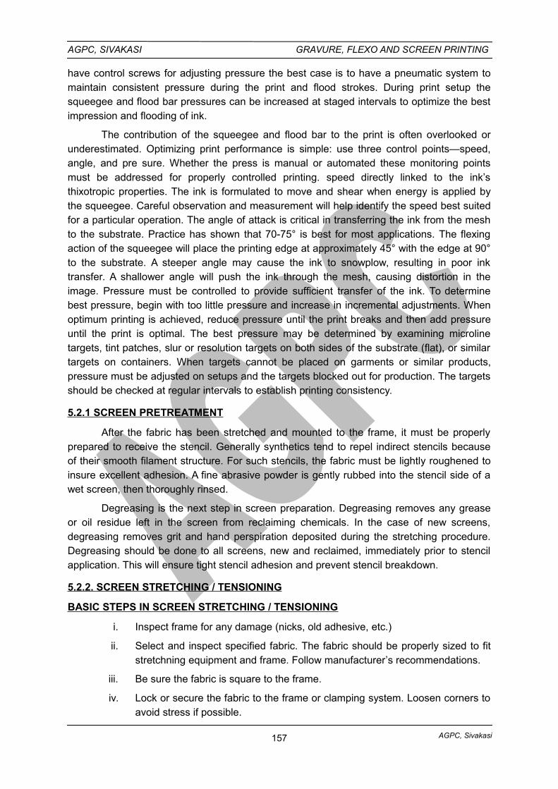
AGPC, Sivakasi
AGPC, SIVAKASI GRAVURE, FLEXO AND SCREEN PRINTING
have control screws for adjusting pressure the best case is to have a pneumatic system tomaintain consistent pressure during the print and flood strokes. During print setup thesqueegee and flood bar pressures can be increased at staged intervals to optimize the bestimpression and flooding of ink.
The contribution of the squeegee and flood bar to the print is often overlooked orunderestimated. Optimizing print performance is simple: use three control points—speed,angle, and pre sure. Whether the press is manual or automated these monitoring pointsmust be addressed for properly controlled printing. speed directly linked to the ink’sthixotropic properties. The ink is formulated to move and shear when energy is applied bythe squeegee. Careful observation and measurement will help identify the speed best suitedfor a particular operation. The angle of attack is critical in transferring the ink from the meshto the substrate. Practice has shown that 70-75° is best for most applications. The flexingaction of the squeegee will place the printing edge at approximately 45° with the edge at 90°to the substrate. A steeper angle may cause the ink to snowplow, resulting in poor inktransfer. A shallower angle will push the ink through the mesh, causing distortion in theimage. Pressure must be controlled to provide sufficient transfer of the ink. To determinebest pressure, begin with too little pressure and increase in incremental adjustments. Whenoptimum printing is achieved, reduce pressure until the print breaks and then add pressureuntil the print is optimal. The best pressure may be determined by examining microlinetargets, tint patches, slur or resolution targets on both sides of the substrate (flat), or similartargets on containers. When targets cannot be placed on garments or similar products,pressure must be adjusted on setups and the targets blocked out for production. The targetsshould be checked at regular intervals to establish printing consistency.
5.2.1 SCREEN PRETREATMENT
After the fabric has been stretched and mounted to the frame, it must be properlyprepared to receive the stencil. Generally synthetics tend to repel indirect stencils becauseof their smooth filament structure. For such stencils, the fabric must be lightly roughened toinsure excellent adhesion. A fine abrasive powder is gently rubbed into the stencil side of awet screen, then thoroughly rinsed.
Degreasing is the next step in screen preparation. Degreasing removes any greaseor oil residue left in the screen from reclaiming chemicals. In the case of new screens,degreasing removes grit and hand perspiration deposited during the stretching procedure.Degreasing should be done to all screens, new and reclaimed, immediately prior to stencilapplication. This will ensure tight stencil adhesion and prevent stencil breakdown.
5.2.2. SCREEN STRETCHING / TENSIONING
BASIC STEPS IN SCREEN STRETCHING / TENSIONING
i. Inspect frame for any damage (nicks, old adhesive, etc.)
ii. Select and inspect specified fabric. The fabric should be properly sized to fitstretchning equipment and frame. Follow manufacturer’s recommendations.
iii. Be sure the fabric is square to the frame.
iv. Lock or secure the fabric to the frame or clamping system. Loosen corners toavoid stress if possible.
157
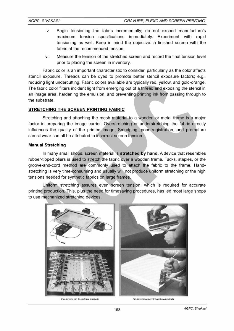
AGPC, Sivakasi
AGPC, SIVAKASI GRAVURE, FLEXO AND SCREEN PRINTING
v. Begin tensioning the fabric incrementally; do not exceed manufacture’smaximum tension specifications immediately. Experiment with rapidtensioning as well. Keep in mind the objective: a finished screen with thefabric at the recommended tension.
vi. Measure the tension of the stretched screen and record the final tension levelprior to placing the screen in inventory.
Fabric color is an important characteristic to consider, particularly as the color affectsstencil exposure. Threads can be dyed to promote better stencil exposure factors; e.g.,reducing light undercutting. Fabric colors available are typically red, yellow, and gold-orange.The fabric color filters incident light from emerging out of a thread and exposing the stencil inan image area, hardening the emulsion, and preventing printing ink from passing through tothe substrate.
STRETCHING THE SCREEN PRINTING FABRIC
Stretching and attaching the mesh material to a wooden or metal frame is a majorfactor in preparing the image carrier. Overstretching or understretching the fabric directlyinfluences the quality of the printed image. Smudging, poor registration, and prematurestencil wear can all be attributed to incorrect screen tension.
Manual Stretching
In many small shops, screen material is stretched by hand. A device that resemblesrubber-tipped pliers is used to stretch the fabric over a wooden frame. Tacks, staples, or thegroove-and-cord method are commonly used to attach the fabric to the frame. Hand-stretching is very time-consuming and usually will not produce uniform stretching or the hightensions needed for synthetic fabrics on large frames.
Uniform stretching assures even screen tension, which is required for accurateprinting production. This, plus the need for timesaving procedures, has led most large shopsto use mechanized stretching devices.
Fig. Screens can be stretched mechanicallyFig. Screens can be stretched manually
158
AGPC, Sivakasi
AGPC, SIVAKASI GRAVURE, FLEXO AND SCREEN PRINTING
Machine Stretching
Most machines used for stretching are either mechanically or pneumaticallycontrolled. In either system, the procedure is basically the same. The screen fabric is cutslightly larger than the frame to allow a series of grippers or stretcher bars to suspend itabove and outside the frame edges. The mesh is stretched to a specific tension percentagewhich is dependent upon the type of fabric and mesh count.
A tension meter is a precision instrument used to measure the surface tension of thestretched screen fabric. Obtaining a specific tension level affects print sharpness, register,printing ink density, and stencil life. The tension meter consists of an indicator dial and aspring-loaded measuring bar supported by metal beams. When a tension meter is placed onthe screen fabric, the tension meter’s measuring bar pushes into the fabric. As the screentension increases, so does the pressure on the measuring bar, and the tension is indicatedon the dial. The tension variation within a screen should not vary by more than +0.5newton/centimeter (N/cm) for high-quality printing and +1.0 N/cm for an average-quality job.The allowable variation between screens is just slightly higher: +1.0 N/cm for exact register,and +1.5 N/cm for average register.
Using a tension meter with a mechanized stretching device can make it possible toobtain the correct tension for screen printing and to duplicate tension accurately from screento screen.
In addition to separate machines and devices used to stretch the fabric off the frame,some frames have a built-in mechanical stretching system. Basically, these devices arecomposed of a hollow aluminum frame with adjustable gripper bars housed inside that holdthe mesh securely. A series of tension bolts, which are accessible from the outside frameedge, are tightened, causing the gripper bars to pull the mesh in a straight outward direction.
Fig. A Tension meter is used to ensure proper screen tension
5.3. SCREEN PRINTING MACHINES
5.3.1. CONTAINER PRINTING MACHINES
These machines are designed on the cylinder-bed principle. The curved surface ofthe printing cylinder is replaced by the curved surface of the container, which is supported bytwo roller bearings. The printing action is exactly the same as on the cylinder press; thescreen reciprocates over the rotating container while the stationary squeegee forces the inkthrough the screen. The machines are usually an integral part of the container making and
159
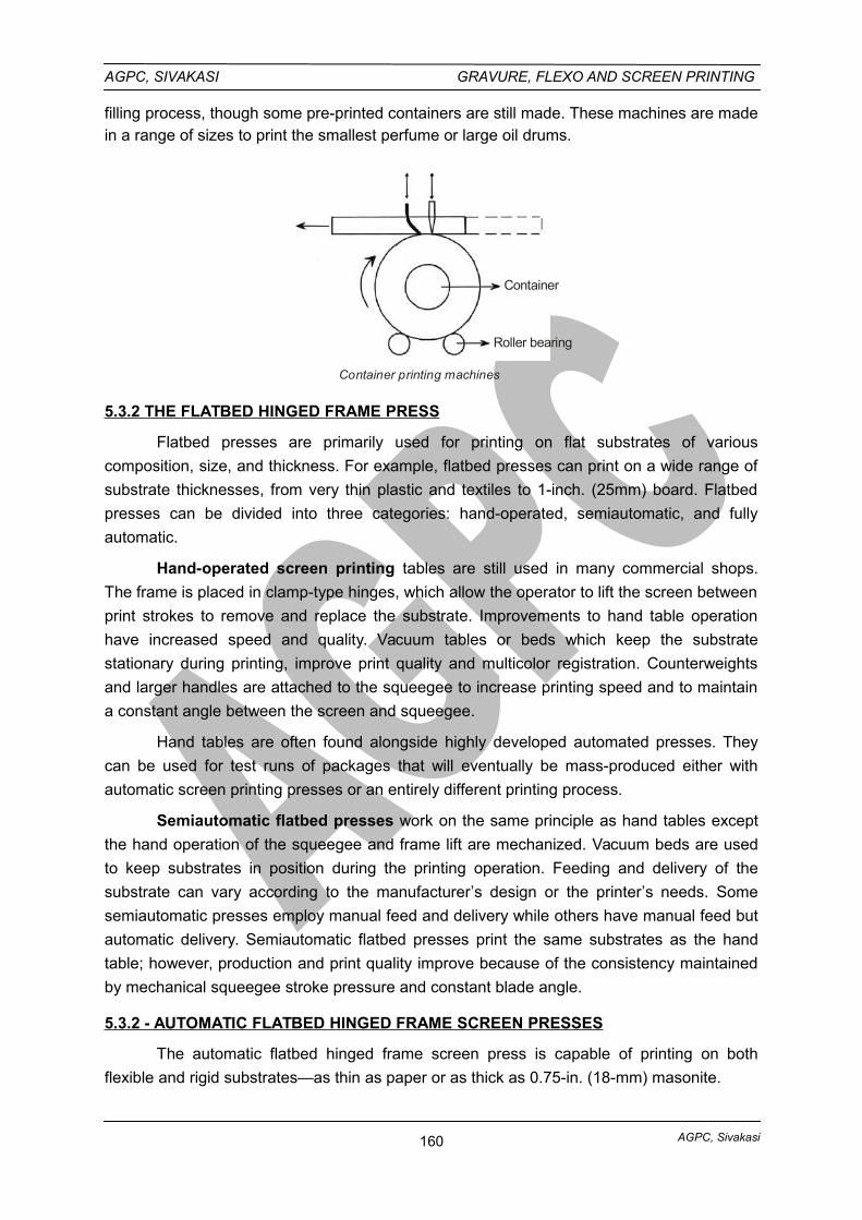
AGPC, Sivakasi
AGPC, SIVAKASI GRAVURE, FLEXO AND SCREEN PRINTING
filling process, though some pre-printed containers are still made. These machines are madein a range of sizes to print the smallest perfume or large oil drums.
Container
Roller bearing
Container printing machines
5.3.2 THE FLATBED HINGED FRAME PRESS
Flatbed presses are primarily used for printing on flat substrates of various
composition, size, and thickness. For example, flatbed presses can print on a wide range of
substrate thicknesses, from very thin plastic and textiles to 1-inch. (25mm) board. Flatbed
presses can be divided into three categories: hand-operated, semiautomatic, and fully
automatic.
Hand-operated screen printing tables are still used in many commercial shops.
The frame is placed in clamp-type hinges, which allow the operator to lift the screen between
print strokes to remove and replace the substrate. Improvements to hand table operation
have increased speed and quality. Vacuum tables or beds which keep the substrate
stationary during printing, improve print quality and multicolor registration. Counterweights
and larger handles are attached to the squeegee to increase printing speed and to maintain
a constant angle between the screen and squeegee.
Hand tables are often found alongside highly developed automated presses. They
can be used for test runs of packages that will eventually be mass-produced either with
automatic screen printing presses or an entirely different printing process.
Semiautomatic flatbed presses work on the same principle as hand tables except
the hand operation of the squeegee and frame lift are mechanized. Vacuum beds are used
to keep substrates in position during the printing operation. Feeding and delivery of the
substrate can vary according to the manufacturer’s design or the printer’s needs. Some
semiautomatic presses employ manual feed and delivery while others have manual feed but
automatic delivery. Semiautomatic flatbed presses print the same substrates as the hand
table; however, production and print quality improve because of the consistency maintained
by mechanical squeegee stroke pressure and constant blade angle.
5.3.2 - AUTOMATIC FLATBED HINGED FRAME SCREEN PRESSES
The automatic flatbed hinged frame screen press is capable of printing on both
flexible and rigid substrates—as thin as paper or as thick as 0.75-in. (18-mm) masonite.
160
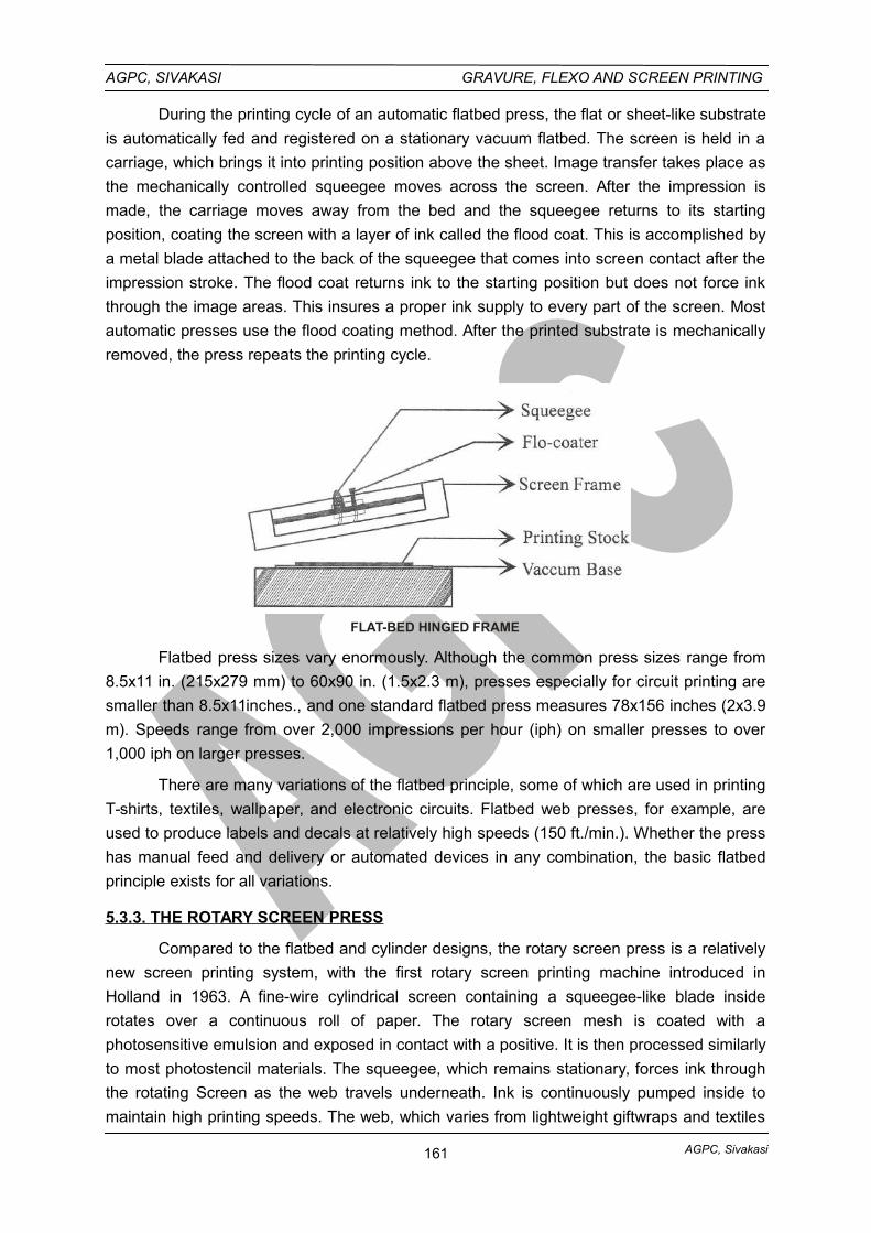
AGPC, Sivakasi
AGPC, SIVAKASI GRAVURE, FLEXO AND SCREEN PRINTING
During the printing cycle of an automatic flatbed press, the flat or sheet-like substrate
is automatically fed and registered on a stationary vacuum flatbed. The screen is held in a
carriage, which brings it into printing position above the sheet. Image transfer takes place as
the mechanically controlled squeegee moves across the screen. After the impression is
made, the carriage moves away from the bed and the squeegee returns to its starting
position, coating the screen with a layer of ink called the flood coat. This is accomplished by
a metal blade attached to the back of the squeegee that comes into screen contact after the
impression stroke. The flood coat returns ink to the starting position but does not force ink
through the image areas. This insures a proper ink supply to every part of the screen. Most
automatic presses use the flood coating method. After the printed substrate is mechanically
removed, the press repeats the printing cycle.
FLAT-BED HINGED FRAME
Flatbed press sizes vary enormously. Although the common press sizes range from
8.5x11 in. (215x279 mm) to 60x90 in. (1.5x2.3 m), presses especially for circuit printing are
smaller than 8.5x11inches., and one standard flatbed press measures 78x156 inches (2x3.9
m). Speeds range from over 2,000 impressions per hour (iph) on smaller presses to over
1,000 iph on larger presses.
There are many variations of the flatbed principle, some of which are used in printing
T-shirts, textiles, wallpaper, and electronic circuits. Flatbed web presses, for example, are
used to produce labels and decals at relatively high speeds (150 ft./min.). Whether the press
has manual feed and delivery or automated devices in any combination, the basic flatbed
principle exists for all variations.
5.3.3. THE ROTARY SCREEN PRESS
Compared to the flatbed and cylinder designs, the rotary screen press is a relatively
new screen printing system, with the first rotary screen printing machine introduced in
Holland in 1963. A fine-wire cylindrical screen containing a squeegee-like blade inside
rotates over a continuous roll of paper. The rotary screen mesh is coated with a
photosensitive emulsion and exposed in contact with a positive. It is then processed similarly
to most photostencil materials. The squeegee, which remains stationary, forces ink through
the rotating Screen as the web travels underneath. Ink is continuously pumped inside to
maintain high printing speeds. The web, which varies from lightweight giftwraps and textiles
161
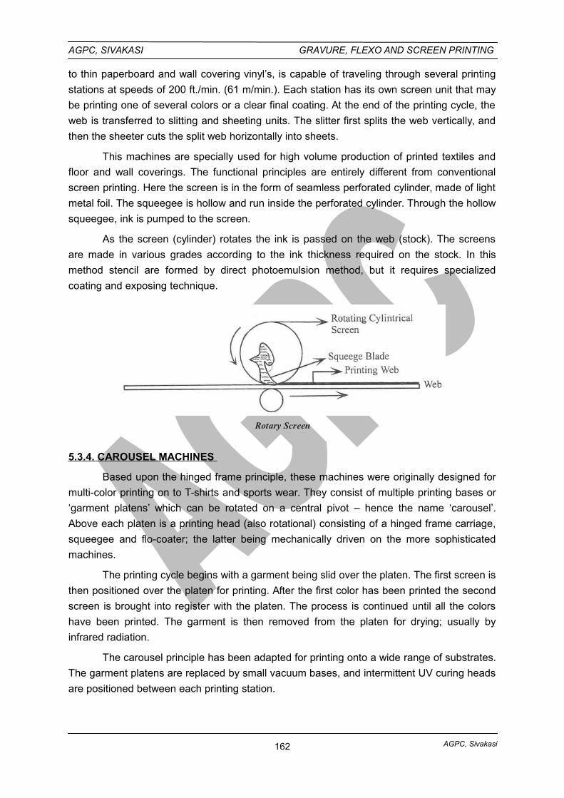
AGPC, Sivakasi
AGPC, SIVAKASI GRAVURE, FLEXO AND SCREEN PRINTING
to thin paperboard and wall covering vinyl’s, is capable of traveling through several printing
stations at speeds of 200 ft./min. (61 m/min.). Each station has its own screen unit that may
be printing one of several colors or a clear final coating. At the end of the printing cycle, the
web is transferred to slitting and sheeting units. The slitter first splits the web vertically, and
then the sheeter cuts the split web horizontally into sheets.
This machines are specially used for high volume production of printed textiles and
floor and wall coverings. The functional principles are entirely different from conventional
screen printing. Here the screen is in the form of seamless perforated cylinder, made of light
metal foil. The squeegee is hollow and run inside the perforated cylinder. Through the hollow
squeegee, ink is pumped to the screen.
As the screen (cylinder) rotates the ink is passed on the web (stock). The screens
are made in various grades according to the ink thickness required on the stock. In this
method stencil are formed by direct photoemulsion method, but it requires specialized
coating and exposing technique.
Rotary Screen
5.3.4. CAROUSEL MACHINES
Based upon the hinged frame principle, these machines were originally designed for
multi-color printing on to T-shirts and sports wear. They consist of multiple printing bases or
‘garment platens’ which can be rotated on a central pivot – hence the name ‘carousel’.
Above each platen is a printing head (also rotational) consisting of a hinged frame carriage,
squeegee and flo-coater; the latter being mechanically driven on the more sophisticated
machines.
The printing cycle begins with a garment being slid over the platen. The first screen is
then positioned over the platen for printing. After the first color has been printed the second
screen is brought into register with the platen. The process is continued until all the colors
have been printed. The garment is then removed from the platen for drying; usually by
infrared radiation.
The carousel principle has been adapted for printing onto a wide range of substrates.
The garment platens are replaced by small vacuum bases, and intermittent UV curing heads
are positioned between each printing station.
162
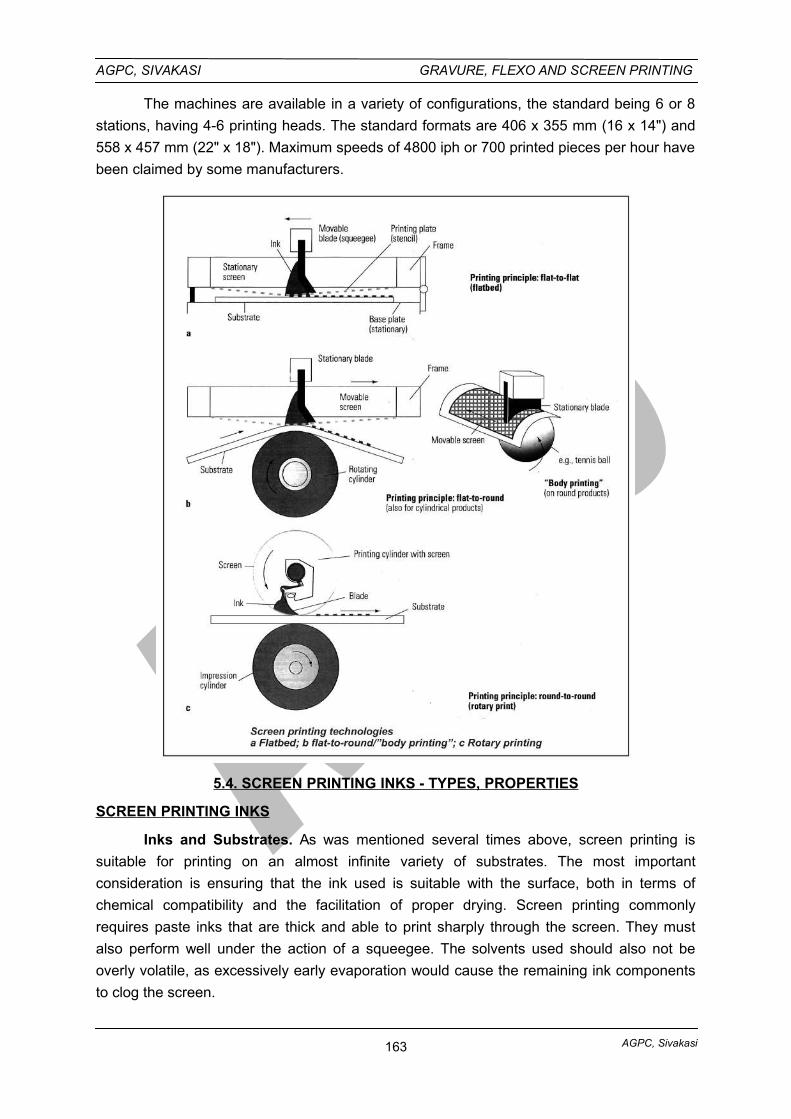
AGPC, Sivakasi
AGPC, SIVAKASI GRAVURE, FLEXO AND SCREEN PRINTING
The machines are available in a variety of configurations, the standard being 6 or 8
stations, having 4-6 printing heads. The standard formats are 406 x 355 mm (16 x 14") and
558 x 457 mm (22" x 18"). Maximum speeds of 4800 iph or 700 printed pieces per hour have
been claimed by some manufacturers.
5.4. SCREEN PRINTING INKS - TYPES, PROPERTIES
SCREEN PRINTING INKS
Inks and Substrates. As was mentioned several times above, screen printing is
suitable for printing on an almost infinite variety of substrates. The most important
consideration is ensuring that the ink used is suitable with the surface, both in terms of
chemical compatibility and the facilitation of proper drying. Screen printing commonly
requires paste inks that are thick and able to print sharply through the screen. They must
also perform well under the action of a squeegee. The solvents used should also not be
overly volatile, as excessively early evaporation would cause the remaining ink components
to clog the screen.
163
AGPC, Sivakasi
AGPC, SIVAKASI GRAVURE, FLEXO AND SCREEN PRINTING
Screen inks typically utilize a drying-oil vehicle, although ultraviolet-curing inks and
other forms of fast-drying inks are making strong inroads in screen printing. Often, in the
decoration of fabrics, glassware, and ceramics, heat transfer printing is utilized, which
involves screen printing the design onto a decal (in one of a variety of ways; see Decal),
then transferring the design (which is composed of sublimable dyes) to the desired end
substrate by means of exposing the decal to increased heat and pressure. (See Heat
Transfer Printing).
COMPONENTS OF INKS AND INK SYSTEMS
The principle components of a printing ink are pigments or dyes (colorants), vehicles,
and additives. An ink can be opaque or trans parent, depending on the ink’s components.
COLORANTS
All printing inks consist of a colorant, almost always a pigment but occasionally adye. Dyes are soluble in a solvent or vehicle, while pigments are insoluble.
Pigments are finely ground solid materials that impart colors to inks. The nature andamount of pigment that an ink contains, as well as the type of vehicle, contribute to the ink’sbody and working properties.
Pigments can be organic or inorganic. Organic pigments tend to produce transparentinks, which are used for process-color printing, while inorganic pigments tend to produceopaque inks.
The term organic means “derived from living organisms.” Organic pigments are madefrom petroleum products: blacks by burning gas or oil, other colors be reacting organicchemicals derived from petroleum. The most common black pigment, furnace black, is madeby burning atomized mineral oil in brick-lined furnaces with a carefully controlled supply ofair. The products of combustion are cooled, and the pigment is collected with electronicprecipitators or in bag filters.
Inorganic pigments are formed by precipitation—that is, by mixing chemicals thatreact to form the insoluble pigment, which then precipitates, or settles out. The mostcommon white inorganic pigment is titanium dioxide. Inks made from titanium oxide are veryopaque and have excellent colorfastness
VEHICLES
The vehicle carries the pigment and adheres it to the substrate. In addition, it givesan ink its consistency. The vehicle is composed mostly of a varnish, which is a solvent plusresin and/or drying oil, along with waxes, driers, and other additives. The vehicle carries thepigment, controls the flow of the ink or varnish on the press, and, after drying, binds thepigment to the substrate. Vehicles also control the film properties of dried ink, such as glossand rub resistance. The resins are formulated to optimize the ink’s ability to adhere to asubstrate.
The solvent serves to maintain the vehicle’s flow until curing. The solvent is carefullyselected for its compatibility with the vehicle and the substrate. Different ink systems usespecific solvents to enable the ink to function properly.
164
AGPC, Sivakasi
AGPC, SIVAKASI GRAVURE, FLEXO AND SCREEN PRINTING
The solvent in the ink can flash off during curing. The solvent products are termedvolatile organic compounds (VOCs) and are regulated by government agencies. Most inksystems producing VOCs contain petroleum-derived solvents. Consult the Material SafetyData Sheets (MSDS) for the content of the ink system. Note handling and disposalinstructions as well.
ADDITIVES
Most ink systems offer greater versatility through additives, which change an ink’sout-of-the-can personality. Toners will provide greater color strength while mixing, andhalftone bases reduce color strength. Thinners will change viscosity, and adhesionpromoters improve adhesion. The printer must consult with the ink supplier concerning theuse of additives. Improper use typically results in poor ink performance.
5.4.1 - TYPES OF SCREEN PRINTING INKS (FOR SPECIFIC APPLICATIONS)
i. INKS FOR DECALCOMANIAS
Pressure-sensitive decals or waterslide decal transfers are usually printed by screenbecause the process delivers thick, opaque films with enough flexibility to withstand themovement of the carrier paper while they are being transferred. These inks usually requiregood light resistance. UV inks have been used to successfully screen-print pressure-sensitive decals.
ii. INKS FOR CIRCUIT BOARDS
When a thick film is required on a printed circuit, the screen printing process is oftenthe best way to print it. The ink must adhere to clean copper and resist the chemicals used inetching the copper to produce the circuit. If it is necessary that the ink be removed with asolvent or alkali after etching, the ink must be sensitive to solvent or alkali.
iii. POSTER INKS
Posters are printed with poster inks on a variety of board and paper stocksNonoxidizing resins and oxidative drying inks are used the most. Overprinting with a glossvarnish extends the life of the print.
iv. ENAMEL INKS FOR METALS
Enamel inks formulated from oil-based alkyds modified with melamine or ureaformaldehyde, cellulose lacquer, epoxies, and other synthetic resins yield attractive signs foroutdoor use.
The metal surface must be thoroughly degreased; aluminum is often anodized orgiven a nitrocellulose wash for the ink to adhere well. Baking enamels yields a product that istough and has good resistance to aging, light, and weather.
Even more permanent are vitreous-enameled aluminum and steel products. Vitreousenamels are glasslike material or frit ground together with oxide colorants, clay, and water.After degreasing and surface treatment of the aluminum, it may be screen-printed withenamel based on borosilicates and immediately fired (without drying) at very hightemperatures.
165
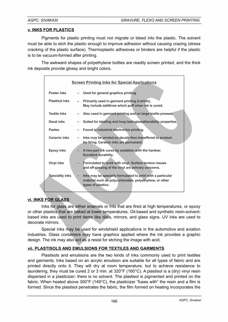
AGPC, Sivakasi
AGPC, SIVAKASI GRAVURE, FLEXO AND SCREEN PRINTING
v. INKS FOR PLASTICS
Pigments for plastic printing must not migrate or bleed into the plastic. The solventmust be able to etch the plastic enough to improve adhesion without causing crazing (stresscracking of the plastic surface). Thermoplastic adhesives or binders are helpful if the plasticis to be vacuum-formed after printing.
The awkward shapes of polyethylene bottles are readily screen printed, and the thickink deposits provide glossy and bright colors.
Plastisol inks Primarily used in garment printing (t-shirts).May include additives which puff when ink is cured.
–
Textile inks Also used in garment printing and on large textile presses.–
Decal inks Suited for labeling and long lasting/weatherability properties.–
Pastes Found in industrial electronics printing.–
Ceramic inks Inks may be printed on decals then transffered to productfor firing. Ceramic inks are permanent.
–
Epoxy inks A two-part ink cures by oxidation with the hardner.Excellent durability.
–
Vinyl inks Formulated to work with vinyl. Surface tension issuesand off-gassing of the vinyl are primary concerns.
–
Speciality inks Inks may be specially formulated to print with a particularmaterial such as polycarbonates, polyethylene, or othertypes of plastics.
–
Poster inks Used for general graphics printing.–
Screen Printing Inks for Special Applications
vi. INKS FOR GLASS
Inks for glass are either enamels or frits that are fired at high temperatures, or epoxyor other plastics that are baked at lower temperatures. Oil-based and synthetic resin-solvent-based inks are used to print items like dials, mirrors, and glass signs. UV inks are used todecorate mirrors.
Special inks may be used for windshield applications in the automotive and aviationindustries. Glass containers may have graphics applied where the ink provides a graphicdesign. The ink may also act as a resist for etching the image with acid.
vii. PLASTISOLS AND EMULSIONS FOR TEXTILES AND GARMENTS
Plastisols and emulsions are the two kinds of inks commonly used to print textilesand garments. Inks based on an acrylic emulsion are suitable for all types of fabric and areprinted directly onto it. They will dry at room temperature, but to achieve resistance tolaundering, they must be cured 2 or 3 min. at 320°F (160°C). A plastisol is a (dry) vinyl resindispersed in a plasticizer; there is no solvent. The plastisol is pigmented and printed on thefabric. When heated above 300°F (149°C), the plasticizer “fuses with” the resin and a film isformed. Since the plastisol penetrates the fabric, the film formed on heating incorporates the
166
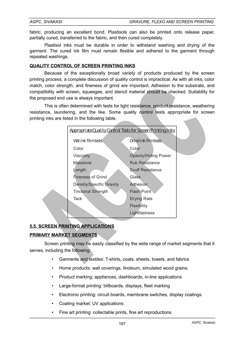
AGPC, Sivakasi
AGPC, SIVAKASI GRAVURE, FLEXO AND SCREEN PRINTING
fabric, producing an excellent bond. Plastisols can also be printed onto release paper,partially cured, transferred to the fabric, and then cured completely.
Plastisol inks must be durable in order to withstand washing and drying of thegarment. The cured ink film must remain flexible and adhered to the garment throughrepeated washings.
QUALITY CONTROL OF SCREEN PRINTING INKS
Because of the exceptionally broad variety of products produced by the screenprinting process, a complete discussion of quality control is impractical. As with all inks, colormatch, color strength, and fineness of grind are important. Adhesion to the substrate, andcompatibility with screen, squeegee, and stencil material should be checked. Suitability forthe proposed end use is always important.
This is often determined with tests for light resistance, product resistance, weatheringresistance, laundering, and the like. Some quality control tests appropriate for screenprinting inks are listed in the following table.
Appropriate Quality Control Tests for Screen Printing Inks
Color
Viscosity
Masstone
Length
Fineness of Grind
Density/Specific Gravity
Tinctorial Strength
Tack
Wet ink film tests Dried ink film tests
Color
Opacity/Hiding Power
Rub Resistance
Scuff Resistance
Glass
Adhesion
Flash Point
Drying Rate
Flexibility
Lightfastness
5.5. SCREEN PRINTING APPLICATIONS
PRIMARY MARKET SEGMENTS
Screen printing may be easily classified by the wide range of market segments that it
serves, including the following:
• Garments and textiles: T-shirts, coats, sheets, towels, and fabrics
• Home products: wall coverings, linoleum, simulated wood grains.
• Product marking: appliances, dashboards, in-line applications
• Large-format printing: billboards, displays, fleet marking
• Electronic printing: circuit boards, membrane switches, display coatings
• Coating market: UV applications
• Fine art printing: collectable prints, fine art reproductions
167
AGPC, Sivakasi
AGPC, SIVAKASI GRAVURE, FLEXO AND SCREEN PRINTING
• Poster printing: low-volume displays
These market segments point once again to the diverse applications for graphic
communication and manufacturing that screen printing affords.
Applications
Screen Printing on Flat Surfaces
Posters and Graphics Printing in Short Print Runs Large-format posters in
particular can be produced relatively conveniently in fairly small print runs. The quite thick ink
film produces coloring that is very brilliant and resistant even with halftone color impressions.
Traffic Routing Systems and Signs. Large printing surfaces for high resistance inks
are found with traffic signs and routing systems. The requirements they impose are best met
using screen printing.
Vehicle Fittings and Instrument Dials.With vehicle fittings a narrow tolerance range
of the translucency of the impression is required in addition to its precision. For example, it
must be possible for control lights to light up in precisely defined colors.
Printed Circuit Boards for Electronics. Due to its simplicity and flexibility, screen
printing is an important process during the development of printed circuit boards for
electronic circuits. Accurate printing onto copper-laminated hard paper or glass-fiber
reinforced epoxy board with etching allowance, solder resist, or assembly designations in the
necessary coating thickness is only possible in large quantities with screen
printing.Restrictions are, however, imposed on the latter as a result of the extreme
miniaturization of components and printed circuit boards.
Photovoltaic. Special conductive pastes are used to print on photoresistors and
solar cells, which serve as the contact points for current transfer. In doing so, particular
importance is placed on high coating thickness in areas that are, at the same time, extremely
small and covered with printed conductors, in order to optimize the efficiency of the energy
production with the solar cells as fully as possible.
Compact Discs (CD). Screen printing is one of the major processes for printing on
CDs. Pad printing and more recently even offset printing are also used.
Textiles. The depth of the ink absorption in textiles calls for a large volume of ink to
be supplied and screen printing is the preferable process for applying it. Clothing, canvas
shopping bags, webs of material, and so on, can be printed in both flatbed and rotary screen
printing.
Transfer Images. Screen printing is frequently used to produce transfer images for
ceramic decoration.These images are put together from ceramic pigments for firing. The
pigment’s grain size necessitates the use of a screen mesh that is not too fine. After
detachment the images are removed from the base material and placed on the preburned
bodies by hand. A recognizable feature of these ceramic products is the thick layer of ink.
The images can be placed above or below the glazing.
168
AGPC, Sivakasi
AGPC, SIVAKASI GRAVURE, FLEXO AND SCREEN PRINTING
Decorative Products, Labels, Wallpapers. Seamless decorations such as textile
webs, wallpaper, and other decorative products, as well as labels often require rotary printing
combined with reel material. Special machines are designed for this. Rotary screen printing
with sheet material is used primarily for higher print runs (examples are given in sec. 2.4.3).
Surface Finishing. Transparent varnish can also be applied using screen printing
technology (for spot varnishing, in particular) to finish the printed product.
Screen Printing on Curved Surfaces
Almost anybody that has an even, convex and concave (to a limited extent) not toostructured surface can be printed using screen printing.There are virtually no restrictions withregard to the material of the body to be printed on.
Ceramics can be printed directly with screen printing. Ceramic pigment inks can beused for subsequent baking or just a low durability varnish applied to the glazed product.
It is not always possible to print directly onto plastic components. Surface treatment,for example involving flame treatment, corona charging, or the application of primer is oftennecessary to ensure that the ink adheres.
Bottles. Glass bottles with a baked finish or pretreated plastic bottles for the foodand domestic products sector are printed using the screen printing process.
Toys.Toys, such as balls, and so forth, can be printed in full in several operational
steps.
Glasses. The screen printing process is often used for drinking glass decoration,
with thick coatings of all inks and also gold being applied.
Advertising Media. The type of advertising medium that can be decorated or
provided with some other overprinting by the screen printing process ranges from cigarette
lighters or ballpoint pens to pocket knives and pocket calculators.
PRODUCTS PRINTED BY SCREEN
Decalcomanias. Pressure-sensitive decals or waterslide decal transfers are usually
printed by screen because the process delivers thick, opaque films with enough flexibility to
with stand the movement of the carrier paper while they are being transferred. These inks
usually require good light resistance UV inks have been used to successfully screen-print
pressure sensitive decals.
Circuit boards. When a thick film is required on a printed circuit, screen process is
often the best way to print it. The ink must adhere to clean copper and resist the chemicals
used in etching the copper to produce the circuit. If it is necessary that the ink be removed
with a solvent or alkali after etching, the ink must be sensitive to solvent or alkali.
Posters. Posters are printed with poster inks on a variety board and paper stocks;
they may be clay-coated, patent-coated, or liner. Clay-coated board is well suited for
photographic halftone printing. Nonoxidizing resins and oxidative drying inks are used the
most. Overprinting with a gloss varnish extends the life of the print.
169
AGPC, Sivakasi
AGPC, SIVAKASI GRAVURE, FLEXO AND SCREEN PRINTING
Metals. Enamel inks formulated from oil-based alkyds modified with melamine or
urea formaldehyde, cellulose lacquer, epoxies, and other synthetic resins yield attractive
signs for outdoor use.
The metal surface must be thoroughly degreased; aluminum is often anodized or
given a nitrocellulose wash to improve ink adhesion. Baking enamel inks yields a product
that is tough and has good resistance to aging, light, and weather.
Even more permanent are vitreous-enameled aluminum and steel products.
Vitreous enamels are glasslike material or frit ground together with oxide colorants, clay,
and water. After degreasing and surface treatment of the aluminum, it may be screen-printed
with enamel based on borosilicates and immediately fired (without drying) at very high
temperatures.
Plastics. Thermoplastic adhesives or binders for inks are helpful if the plastic is to be
vacuum-formed after printing. Pigments for plastic printing must not migrate or bleed into the
plastic. The solvent must be able to etch the plastic enough to improve adhesion without
causing crazing (stress cracking of the plastic surface).
The awkward shapes of plastic bottles are readily screenprinted, and the thick ink
deposits provide bright, glossy colors.
Glass. Inks for glass are either enamels or frits that are fired at high temperatures, or
epoxy or other plastics that are baked at lower temperatures. Oil-based and synthetic
resinsolvent-based inks are used to print items like dials, mirrors, and glass signs. W inks
are used to decorate mirrors.
Textiles. Plastisols and emulsions are the two kinds of inks commonly used to print
textiles. Inks based on an acrylic emulsion are suitable for all types of fabric and are printed
directly onto it. They will dry at room temperature, but to achieve resistance to laundering,
they must be cured 2 or 3 min. at 320°F (160°C). A plastisol is a (dry) vinyl resin dispersed in
a plasticizer; there is no solvent. The plastisol is pigmented and printed on the fabric. When
heated above 300°F (150°C), the plasticizer “fuses with” the resin and a film is formed. Since
the plastisol penetrates the fabric, the film formed on heating incorporates the fabric,
producing an excellent bond. Plastisols can also be printed onto release paper, partially
cured, transferred to the fabric, and then cured completely.
Membrane touch switches. These switches, seen at checkout counters at fast-food
restaurants and supermarkets, on electronic games, on appliances, medical equipment, and
many other electronic devices, provide a major market for screen printing. They are made of
three layers of synthetic film the circuit layer, a spacer, and a graphic overlay.
The circuit is usually applied to a polyester (PET) film by screen printing with
conductive inks, which are typically blends of nonconductive, organic binders and conductive
particles, usually silver or graphite. The ink is cured at temperatures around 300°F (160°C)
to achieve the desired conductivity. Polyester is preferred because of its chemical resistance
and its ability to withstand the high curing temperature. Polyester shows good resistance to
flex fatigue, cracking, and deformation, and conductive inks work well on polyester.
170
AGPC, Sivakasi
AGPC, SIVAKASI GRAVURE, FLEXO AND SCREEN PRINTING
The space layer (or spacer) holds the circuit layer and overlay sheets in register and
keeps them apart except when the switch is depressed. The film has pressure-sensitive
adhesive on both sides and is diecut at the locations of each switch. To assure that this layer
expands and contracts at the same rate as the other layers, it is typically made of PET film.
The graphic overlay is usually made of PET, but polycarbonate is sometimes used. It
must withstand the flexing for the designed life of the device, and PET is reported to
withstand 100 million switchings. This layer is decorated with screen inks, often on the back
side (or second surface), which protects the print from scratching and abrasion. This
structure is visually summarized in figure 6-1.
Trouble- shooting
For the ink manufacturer to help solve ink problems, the printer should be ready to
supply the following information:
• Screen material (e.g., monofilament, nylon)
• Mesh size (e.g., 160)
• Stencil material (e.g., blackout materials, diazo-sensitized photo screens)
• Squeegee composition (e.g., polyurethane)
• Squeegee hardness and durometer (e.g., hard 66-75 Shore A).
171
AGPC, Sivakasi
AGPC, SIVAKASI GRAVURE, FLEXO AND SCREEN PRINTING
UNIT: V – SCREEN PRINTING
PART - A - 2 Marks Questions
1. Name the device used to measure the squeegee hardness.
Durometer.
2. What is a mesh? / What is the function of screen mesh?
In screen-printing, the fabric’s mesh permits the ink to flow through the image area.
The mesh plays a dominant role in metering the amount of ink that will flow onto the
substrate.
3. What is a squeegee? / State the functions of aqueege.
Squeegee is a rubber or plastic blade attached to a handle, used to force screen
printing ink through the open areas of the stencil and mesh to the substrate.
4. State the various parts of an automatic cylinder screen press.
A screen carriage, a squeegee, an impression cylinder.
5. What is the composition of screen printing inks? / State the main ingredients ofscreen printing inks.
Screen-printing ink consists of pigments or dyes (colorants), vehicles, and additives.
6. Name some of the products printed by screen-printing process.
Posters and displays, greeting cards, name plates, printed circuits, glass bottles, T-
shirts, Textiles, plastic bottles, etc.,.
7. What is the main limitation of Screen Printing?
Halftone printing is limited to coarse screens. Conventional inks requires some time
for drying and requires space consuming racks to allow the printing inks to dry.
8. Name any two applications of screen printing.
Garments and textiles : T-Shirts, Fabrics, Towels, Coats
Large format printing : Bill boards, Displays, Fleet marking.
9. Mention any three kinds of screen printing inks.
Plastic Inks, Glass Inks, Poster Inks, etc.
10. Mention any three applications of screen printing on curved surfaces.
Bottles, Toys, Glasses.
11. State the different meshes used for screen printing.
• Silk
• Polyester
• Nylon
• Wire mesh (or wire cloth)
• Metalised polyester.
172
AGPC, Sivakasi
AGPC, SIVAKASI GRAVURE, FLEXO AND SCREEN PRINTING
12. What are the applications of rotary screen-printing machines?
These machines are specially used for high volume production. These presses are
used to print on textile webs, floor coverings, wallpaper, decorative products, labels, stickers,
office stationery printing, canvas shopping bags, etc.,.
PART - B - 3 Marks Questions
1. What are the various types of screen-printing machines available?
i. Flatbed screen–printing presses
a) Hand operated flatbed press
b) Semi–automatic flatbed press
c) Fully automatic flatbed press
ii. Flatbed vertical lift screen printing presses
iii. Cylinder bed screen printing presses
iv. Container screen printing machines
v. Rotary screen printing presses
vi. Carousal screen printing presses
2. What are different screen squeegees available?
A. Squeegee blades (based on materials)
i) Rubber squeegee blade
ii) Squeegee blade made from synthetic materials
iii) Polyurethane squeegee blade
iv) Polyvinyl squeegee blade
B. Squeegee blades (based on hardness)
i) Extra soft blade (45- 50 durometer)
ii) Soft blade (50 – 60 durometer)
iii) Medium blade (60-70 durometer)
iv) Hard blade (70-90 durometer)
C. Squeegee blades (based on shapes)
i) Square edge blade
ii) Square edge with rounded corners blade
iii) Single sided bevel edge blade
iv) Double sided bevel edge blade
v) Rounded edge blade
vi) Diamond edge blade
173
AGPC, Sivakasi
AGPC, SIVAKASI GRAVURE, FLEXO AND SCREEN PRINTING
3. How screen pretreatment is done?
After the fabric has been stretched and mounted to the frame, it must be properly
prepared to receive the stencil. Generally synthetics tend to repel indirect stencils because
of their smooth filament structure. For such stencils, the fabric must be lightly roughened to
insure excellent adhesion. A fine abrasive powder is gently rubbed into the stencil side of a
wet screen, then thoroughly rinsed.
Degreasing is the next step in screen preparation. Degreasing removes any grease
or oil residue left in the screen from reclaiming chemicals. In the case of new screens,
degreasing removes grit and hand perspiration deposited during the stretching procedure.
Degreasing should be done to all screens, new and reclaimed, immediately prior to stencil
application. This will ensure tight stencil adhesion and prevent stencil breakdown.
4. State the various types of screen printing inks available.
Lacquer inks
Gloss enamel inks
Epoxy inks
Vinyl inks
Fluorescent inks
Phosphorescent inks
Textile inks
Plastisol inks
Catalytic inks
Enamel inks
Special inks for automotive and aviation industry.
5. Write about the properties of screen printing inks.
Screen printing applies the thickest film of any common printing process,
making it excellent for fluorescent and fade resistant inks.
Screen inks do not transfer from one roll to another. Therefore, they are
“short” and “buttery.” Short inks pass through the openings of the screenwithout leaving fuzzy edges.
Most screen inks contain volatile solvents, which represent up to 70% of the
formulation.
Like other sheetfed inks, oil-based screen inks that dry by oxidative
polymerization are normally alkyds based on linseed or another drying oil.
Catalytic-curing inks are often employed for printing bottles or circuit boards.
Most screen inks dry by evaporation: high-velocity, hot-air dryers, wicket
dryers, simple drying racks, flame dryers, and even microwave dryers areused.
174
AGPC, Sivakasi
AGPC, SIVAKASI GRAVURE, FLEXO AND SCREEN PRINTING
PART - C - 10 Marks Questions
1. Explain the various meshes used for screen printing.
2. Describe the different types of squeegees used for screen-printing. How will youselect the squeegees?
3. Describe the different methods of screen tensioning (or stretching).
4. Explain the working principles of automatic flatbed screen-printing machine.
5. Describe the working principles of rotary screen printing press.
6. Explain (a) Container screen-printing machine (b) Carousel printing machine.
7. Describe the different screen printing inks used for various applications.
8. Explain the various applications of screen-printing process.
9. Write notes on (i) Screen Tensioning (ii) Rotary Screen Printing (iii) Screen Mesh.
GLOSSARY
Durometer
A measure of hardness, by using a durometer gauge, either Shore A (for soft rubber)
or Shore D (for harder, less resillient materials).
Transparent Inks
Inks which do not have hiding power (opacity), permitting light to pass through and
selectively absorb light of specific wavelengths; essential to process printing.
175
![3D SCREEN PRINTING MASS PRODUCTION OF ... - · PDF file3D SCREEN PRINTING MASS PRODUCTION OF ... [HB] 3D Metal Printing - Binder Jetting approach ... 2D screen printing is an established](https://img.pdfslide.net/doc/110x75/5aa545cf7f8b9ab4788cecdc/3d-screen-printing-mass-production-of-screen-printing-mass-production.jpg)