Embed Size (px)
Citation preview

Grazing reflection of Gaussian beams
Lee W. Casperson
The reflectivities of most surfaces are higher for grazing or near-90-deg angles of incidence than for moreperpendicular or near-zero-deg angles. Grazing-incidence configurations are especially important in thedevelopment of lasers and optical systems that operate in the far-ultraviolet and soft-x-ray regions of thespectrum, where transparent or highly reflecting media are almost unknown. Analytical solutions of theparaxial wave equation are obtained for the grazing reflection and complex interference effects that takeplace when a Gaussian beam interacts at shallow angles with a reflecting surface. © 1999 OpticalSociety of America
OCIS codes: 140.0140, 240.0240, 260.0260, 350.5500.
rscb
bOgtcl
1. Introduction
It has long been recognized that Gaussian beams,and more generally polynomial-Gaussian beams, aresolutions of the paraxial wave equation in free space.Such modes also arise frequently as the output beamsin laser oscillators. Accordingly, there has been in-tense and continuing interest in the propagation andtransformation of Gaussian beams of various wave-lengths in refracting, reflecting, and diffracting sys-tems. Over the years many such systems have beeninvestigated. It was shown that Gaussian beamsretain their basic functional form when they propa-gate in free space,1 in real lenslike media,2 in complexlenslike media,3 and in other simple elements.4 Off-axis polynomial-Gaussian beams have also beenstudied,5 and their propagation in a range of complexand misaligned systems is now known.6
One of the oldest problems in electromagnetics con-cerns the reflection of electromagnetic waves atboundaries, and this problem has been studied ex-tensively in the Gaussian beam context. The graz-ing reflection of Gaussian beams is investigated here.At grazing incidence the beam might interactstrongly with a reflecting surface for a distance com-parable with or longer than the Rayleigh length.
When this research was performed the author was with theRochester Theory Center for Optical Science and Engineering andthe Institute of Optics, University of Rochester, Rochester, NewYork 14627-0186. His permanent address is the Department ofElectrical Engineering, Portland State University, P.O. Box 751,Portland, Oregon 97207-0751. His email address is [email protected].
Received 6 July 1998.0003-6935y99y030554-09$15.00y0© 1999 Optical Society of America
554 APPLIED OPTICS y Vol. 38, No. 3 y 20 January 1999
Thus the meaning and usefulness of conventionalbeam parameter transformations are not so clear.The actual electromagnetic-field distributions of thereflecting waves are obtained here, including the in-terference terms between the incident and the re-flected waves. For near-normal incidence theintensity or energy density maxima that result fromthis interference are separated by approximately onehalf of the wavelength, a distance that might be smallcompared with most of the macroscopic componentsof an electromagnetic system. The existence and di-mensions of these fringes would be of interest in ap-plications that involve nonlinear media, and theyhave made possible the enhanced resolution of inter-ference scanning optical microscopy.7 In most pre-vious studies of non-normal-incidence reflection theinterference between the incident and the reflectedwaves is not treated, and only the beam parametertransformations are obtained. However, it can benoted that, as the angle of incidence increases, thespacing between the interference fringes also in-creases. At grazing incidence the interferencefringes that result from the superposition of the in-cident and the reflected waves can be comparable inwidth to the Gaussian beam spot size ~1ye amplitudeadius!. In spite of this apparent complication, it ishown here that solutions of the paraxial equationan be found for grazing reflection of a Gaussianeam.An analysis of the grazing reflection of Gaussian
eams can have significant practical implications.ne of the most important reasons for interest inrazing reflectivity is the often dramatic increase inhe reflection coefficient that occurs as angles of in-idence approach 90 deg, and this effect was studiedong before the advent of lasers.8 This angle depen-

mfccbt
15–17
dence might already be important for microwave andvisible wavelengths, but it is most striking for wave-lengths in the vacuum-ultraviolet spectral region.Although there might be other important advantagesto employing grazing reflection, the higher reflectivi-ties that are obtainable have been the motivation formany applications.One of the earliest applications of grazing-incidencereflection was in vacuum-ultraviolet spectroscopy.The low reflectance of all grating materials for wave-lengths below ;300 Å requires the use of grazing-incidence spectrographs for this spectral region. Inthese systems the grating itself can be oriented tohave an angle of incidence of 89 deg or more. By thismeans useful reflectivities and grating efficiencieshave been obtained at wavelengths as low as a fewangstroms. To disperse still shorter wavelengths,as required in spectroscopy, the gratings have beenreplaced with crystals in which the regular latticespacing takes the place of the rulings on a diffractiongrating. Some spectroscopic systems have incorpo-rated two or more grazing-incidence elements.9
With the development of more recent electromag-netic systems, several further applications of grazing-incidence reflection have appeared. One importantexample is in the guiding of optical beams when nosuitable fiber-optic material is available. For exam-ple, in the infrared and the far-infrared portions ofthe spectrum there are wavelength regions for whichlow-loss fiber materials are not yet readily available.Similarly, in the far-ultraviolet and the soft-x-ray re-gions, transparent materials are virtually unknown,whereas grazing reflectivities from metal can be quitehigh. For such wavelengths and for extremely high-power applications, metallic waveguides are some-times a viable option. Thus, in the limit of a 90-degangle of incidence, low-loss waveguided propagationis possible if there is a slight inward curvature of thewaveguiding surface in the direction of propaga-tion.10 If such a waveguiding strip is also curvedappropriately in the transverse direction, it can sup-port low-loss propagation of beam modes at wave-lengths for which other media would be essentiallyopaque.11 The modes can sometimes be representedin terms of Hermite–Gaussian functions transverseto the waveguide and Airy functions in the perpen-dicular direction. If mirrors are placed on the endsof such a waveguide while an amplifying medium isintroduced, it becomes possible to achieve laser oscil-lation. Such lasing has been observed with acontinuous-wave CO2 laser in which the dischargetube was slightly bent12 and in a rf discharge forwhich the waveguide also served as one of the dis-charge electrodes.13 It has also been possible to
atch the mode volume of the fundamental Airy-unction mode to the thin gain layer along the curvedathode of a continuous-wave transverse laser dis-harge.14 This sort of coupling should also be possi-le for a laser with grazing reflection modes of theype described below.
Grazing reflection has also proved to be extremelyuseful in the development of high-power free-electron
lasers. These lasers present difficulties becauseof the high power density of the optical beam thatleaves the gain medium. Even though visible wave-length reflectivities can be quite high for normal in-cidence, it has been found that damage can bereduced substantially by a grazing-incidence orienta-tion of the mirrors closest to the amplifier.18,19
Grazing-incidence components will be even more im-portant with the development of free-electron lasersin the vacuum-ultraviolet and soft-x-ray regions ofthe spectrum. It is notable in the present contextthat Gaussian field distributions are often assumedwhen the modes of these grazing-incidence lasers arerepresented.20,21
Grazing-incidence mirrors are also used with othertypes of laser, and their potential as multibounceturning mirrors and polarizers for soft-x-ray lasersand optical systems has been recognized.22 Also,they can serve as an efficient means for collimatingthe soft-x-ray emission from a laser-produced plasmafor longitudinal pumping of a short-wavelength la-ser.23 Thus grazing-incidence reflectors are findingtheir way into many applications, especially for sys-tems that involve short wavelengths or high powers.In many of these applications the beam profiles canbe well represented by Gaussian functions, and thusthere is value in developing as complete a model aspossible for the reflection of such beams at grazingangles of incidence.
A basic derivation of the Gaussian beam equationsis included in Section 2. The initial purpose of thisderivation is to reduce the partial differential waveequation to a set of first-order ordinary differentialequations that govern the various parameters thatcharacterize the spatially evolving beam. The solu-tions to these simpler equations are discussed in Sec-tion 3 for beam propagation in spatially homogeneousmedia. The grazing reflection of these beams is ex-plored in Section 4.
2. Derivation of the Beam Equations
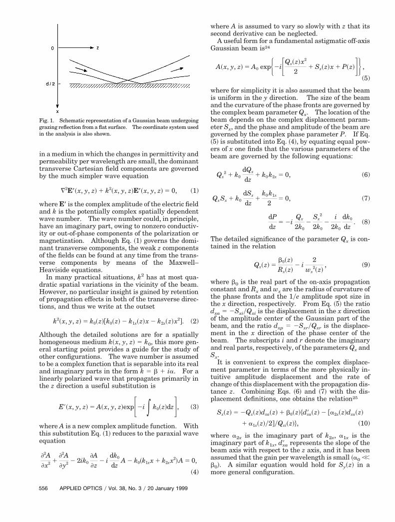
The geometry to be considered here involves a Gauss-ian beam that propagates almost parallel to a reflect-ing surface, as shown schematically in Fig. 1. Thecoordinate system to be employed is also shown inFig. 1. Owing to diffraction and misalignment, thebeam is assumed to interact with the surface oversome extended distance. The complexity of includ-ing this reflecting surface in the propagation analysisleads us to simplify the problem as much as possiblein other ways. Thus the reflecting surface is as-sumed to be highly reflecting and flat, and other sim-plifications concern the propagation medium. Withsuch restrictions it is possible to obtain closed-formanalytic solutions that are not excessively cumber-some.
For any study of electromagnetic-wave propagationthe fundamental starting point is the Maxwell–Heaviside equations. These equations can be com-bined to yield coupled equations that govern thevarious field components of a propagating electro-magnetic beam. For the case of nearly plane waves
20 January 1999 y Vol. 38, No. 3 y APPLIED OPTICS 555
eotalt
eb
ob
p
b
5
in a medium in which the changes in permittivity andpermeability per wavelength are small, the dominanttransverse Cartesian field components are governedby the much simpler wave equation
¹2E*~x, y, z! 1 k2~x, y, z!E*~x, y, z! 5 0, (1)
where E* is the complex amplitude of the electric fieldand k is the potentially complex spatially dependentwave number. The wave number could, in principle,have an imaginary part, owing to nonzero conductiv-ity or out-of-phase components of the polarization ormagnetization. Although Eq. ~1! governs the domi-nant transverse components, the weak z componentsof the fields can be found at any time from the trans-verse components by means of the Maxwell–Heaviside equations.
In many practical situations, k2 has at most qua-dratic spatial variations in the vicinity of the beam.However, no particular insight is gained by retentionof propagation effects in both of the transverse direc-tions, and thus we write at the outset
k2~x, y, z! 5 k0~z!@k0~z! 2 k1x~z!x 2 k2x~z!x2#. (2)
Although the detailed solutions are for a spatiallyhomogeneous medium k~x, y, z! 5 k0, this more gen-ral starting point provides a guide for the study ofther configurations. The wave number is assumedo be a complex function that is separable into its realnd imaginary parts in the form k 5 b 1 ia. For ainearly polarized wave that propagates primarily inhe z direction a useful substitution is
E9~x, y, z! 5 A~x, y, z!expF2i * k0~z!dzG, (3)
where A is a new complex amplitude function. Withthis substitution Eq. ~1! reduces to the paraxial waveequation
]2A]x2 1
]2A]y2 2 2ik0
]A]z
2 idk0
dzA 2 k0~k1xx 1 k2xx
2!A 5 0,
(4)
Fig. 1. Schematic representation of a Gaussian beam undergoinggrazing reflection from a flat surface. The coordinate system usedin the analysis is also shown.
56 APPLIED OPTICS y Vol. 38, No. 3 y 20 January 1999
where A is assumed to vary so slowly with z that itssecond derivative can be neglected.
A useful form for a fundamental astigmatic off-axisGaussian beam is24
A~x, y, z! 5 A0 expH2iFQx~z!x2
21 Sx~z!x 1 P~z!GJ ,
(5)
where for simplicity it is also assumed that the beamis uniform in the y direction. The size of the beamand the curvature of the phase fronts are governed bythe complex beam parameter Qx. The location of thebeam depends on the complex displacement param-eter Sx, and the phase and amplitude of the beam aregoverned by the complex phase parameter P. If Eq.~5! is substituted into Eq. ~4!, by equating equal pow-rs of x one finds that the various parameters of theeam are governed by the following equations:
Qx2 1 k0
dQx
dz1 k0 k2x 5 0, (6)
Qx Sx 1 k0
dSx
dz1
k0 k1x
25 0, (7)
dPdz
5 2iQx
2k02
Sx2
2k02
i2k0
dk0
dz. (8)
The detailed significance of the parameter Qx is con-tained in the relation
Qx~z! 5b0~z!
Rx~z!2 i
2wx
2~z!, (9)
where b0 is the real part of the on-axis propagationconstant and Rx and wx are the radius of curvature ofthe phase fronts and the 1ye amplitude spot size inthe x direction, respectively. From Eq. ~5! the ratiodxa 5 2SxiyQxi is the displacement in the x directionf the amplitude center of the Gaussian part of theeam, and the ratio dxp 5 2SxryQxr is the displace-
ment in the x direction of the phase center of thebeam. The subscripts i and r denote the imaginaryand real parts, respectively, of the parameters Qx andSx.
It is convenient to express the complex displace-ment parameter in terms of the more physically in-tuitive amplitude displacement and the rate ofchange of this displacement with the propagation dis-tance z. Combining Eqs. ~6! and ~7! with the dis-
lacement definitions, one obtains the relation25
Sx~z! 5 2Qx~z!dxa~z! 1 b0~z!$d9xa~z! 2 @a2x~z!dxa~z!
1 a1x~z!y2#yQxi~z!%, (10)
where a2x is the imaginary part of k2x, a1x is theimaginary part of k1x, d9xa represents the slope of thebeam axis with respect to the z axis, and it has beenassumed that the gain per wavelength is small ~a0 ,,
0!. A similar equation would hold for Sy~z! in amore general configuration.

ggptaBsGre
cr
T
sa~
Many solutions have been obtained for the param-eters governed by Eqs. ~6!–~8!. The evolution of thebeam parameter Qx ~or accordingly the spot size andphase front curvature! has been examined in thereatest depth, whereas much less attention has beeniven to the detailed solutions of the displacementarameter equations and their applications. No de-ailed studies of the phase parameter for general off-xis Gaussian beams appear to have been made.ecause interference effects are essential for thetudy of the intensity distribution of a reflectingaussian beam, it is necessary here also to obtain
igorous solutions to Eq. ~8!, the phase parameterquation.As indicated above, we focus here on the simplest
ase of a spatially homogeneous medium with theeal propagation constant b0. Typically, this me-
dium would be meant to represent free space. Inthis case Eqs. ~6!–~8! reduce to
Qx2 1 b0
dQx
dz5 0, (11)
Qx Sx 1 b0
dSx
dz5 0, (12)
dPdz
5 2iQx
2b02
Sx2
2b0. (13)
We can also note from Eq. ~10! that in this limit thecomplex displacement parameter is given in terms ofthe beam location by
Sx~z! 5 2Qx~z!dxa~z! 1 b0 d9xa~0!
5 2Qx~z!dxa~0! 1 @b0 2 Qx~z!z#d9xa~0!, (14)
where use has been made of the fact that in a uniformmedium the rate of change of the amplitude displace-ment is constant, whereas the displacement itselfvaries linearly with z.
3. Propagation in a Uniform Media
In Section 2 a set of beam modes was derived that candescribe the distribution of electromagnetic fields asthey propagate in spatially homogeneous real dielec-tric media. In this process the partial differentialwave equation was reduced to a set of ordinary dif-ferential equations. Our solutions are not completeuntil these secondary beam parameter equationshave actually been solved. Thus it is now necessaryto solve the coupled ordinary first-order differentialequations given above as Eqs. ~11!–~13!.
One can readily show that the solution to Eq. ~11!has the familiar form
1qx~z!
51yqx1
1 1 zyqx1, (15)
where 1yqx1 is the initial ~z 5 0! value of 1yqx~z! andwhere we replace Eq. ~9! with the standard low-gain-per-wavelength form of the beam parameter:
Qx~z!
b05
1qx~z!
51
Rx~z!2
ilnpwx
2~z!. (16)
In this expression l is the vacuum wavelength and nis the index of refraction. With Eqs. ~15! and ~16!,Eq. ~12! can be rewritten in the form
1Sx~z!
dSx~z!
dz5 2
1yqx1
1 1 zyqx1. (17)
One readily finds that the solution of this equationcan be written as
Sx~z! 5Sx1
1 1 zyqx1, (18)
where Sx1 is the initial value of Sx~z!. With Eqs. ~15!and ~18!, the phase parameter equation given aboveas Eq. ~13! takes the form
dP~z!
dz5 2
i2
1yqx1
1 1 zyqx12
Sx12y2b0
~1 1 zyqx1!2 . (19)
his equation can also be integrated, and the result is
P~z! 5 P1 2i2
lnS1 1z
qx1D 2
Sx12qx1
2b0
zyqx1
1 1 zyqx1, (20)
where P1 is the initial value of P~z!. When the var-ious parameter formulas obtained here are intro-duced into Eq. ~5!, one has a complete description ofthe propagation of the fundamental off-axis Gaussianbeam in real uniform media.
We can explore the significance and applications ofthese results more readily by focusing on specificcases. It follows from Eq. ~16! that if the startingposition of the beam is at the beam waist ~Rx1 5 `!the beam parameter there must be purely imaginary.By convention we use the notation 1yqx1 5 2iyz0,where z0 is the Rayleigh length. With this substi-tution Eq. ~15! becomes
1qx~z!
52iyz0
1 2 izyz0. (21)
When combined with Eq. ~16!, Eq. ~21! yields thetandard formulas for the propagation of the spot sizend the phase-front curvature, whereas Eqs. ~18! and20! become
Sx~z! 5Sx1
1 2 izyz0, (22)
P~z! 5 P1 2i2
lnS1 2izz0D 2
Sx12z0
2b0
zyz0
1 2 izyz0. (23)
As noted above, it is convenient to express the com-plex displacement parameter Sx in terms of the ac-tual displacement of the amplitude center of thebeam dxa and the rate of change of this parameter
20 January 1999 y Vol. 38, No. 3 y APPLIED OPTICS 557

wtbIdl5
ri
i
A
5
with the propagation distance. Combining Eqs.~14!, ~16!, and ~21!, one finds that the complex dis-placement parameter can be written as
Sx~z! 5 2b0
z0F ~zyz0! 2 i1 1 ~zyz0!
2G Fdxa~0! 1zz0
ddxa
d~zyz0!G
1b0
z0
ddxa
d~zyz0!
5 22
w02 F ~zyz0! 2 i
1 1 ~zyz0!2G Fdxa~0!1
zz0
ddxa
d~zyz0!G
12
w02
ddxa
d~zyz0!, (24)
here the formula for the Rayleigh length in terms ofhe spot size at the beam waist z0 5 npw0
2yl haseen used to eliminate the propagation constant b0.t is also convenient to normalize distances in theirection of propagation with respect to the Rayleighength by introduction of the normalized distance z9
zyz0. With this substitution Eq. ~24! can be re-written more compactly:
Sx~z9! 5 22
w02 S z9 2 i
1 1 z92D Sdxa~0! 1 z9ddxa
dz9 D 12
w02
ddxa
dz9.
(25)Finally, it is also helpful to normalize the spot size
and beam displacement to an arbitrary distance d:
Sx~z9! 5 22 S z9 2 i1 1 z92D p1 1 z9v1
w902d
1 2v1
w902d
. (26)
In this result the normalized spot size w90 5 w0yd, theinitial position in the x direction p1 5 dxayd, and theate of change of this position with respect to normal-zed distance in the z direction v1 5 dp1ydz9 have
been introduced. The initial value of the complexdisplacement parameter is needed for substitution inthe phase parameter formulas, and from Eq. ~26! thisinitial value is
Sx1 5 2v1 1 ip1
w902d
. (27)
By use of Eq. ~27! with simplifications similar tothose used for the complex displacement parameter,the phase parameter result given in Eq. ~23! takesthe form
P~z9! 5 P1 2i2
ln~1 2 iz9! 2z9
w902 F~v1 1 ip1!
2
1 2 iz9 G5 2
i2
$ln~1 1 z92!1y2 2 i tan21~z9!# 2z9
w092
3@~v1
2 2 p12! 2 2v1 p1 z9# 1 i@~v1
2 2 p12!z9 1 2v1 p1#
1 1 z92 ,
(28)
where the initial value of the phase has been setarbitrarily to zero. Now the parameter functions
58 APPLIED OPTICS y Vol. 38, No. 3 y 20 January 1999
given in Eqs. ~21!, ~26!, and ~28! can be substitutednto Eq. ~5!, and the field is found to be
~x9, z9! 5 A0 expHF21
w902~1 1 z92!
2 iz9
w902~1 1 z92!Gx92
1 F2~p1 1 z9v1!
w902~1 1 z92!
1 i2z9~p1 1 z9v1!
w902~1 1 z92!
2 i2v1
w902Gx9 1 F2ln~1 1 z92!1y4
2z92~v1
2 2 p12! 1 2z9v1 p1
w902~1 1 z92!
1 iz9~v1
2 2 p12! 2 2z92v1 p1
w902~1 1 z92!
1i2
tan21~z9!GJ , (29)
where the transverse coordinate has been normalizedaccording to x9 5 xyd.
It is convenient for many purposes to deal with theintensity of the beam rather than the amplitude.We define the intensity with the relation
I~x9, z9! 5 A*~x9, z9!A~x9, z9!. (30)We also choose the amplitude coefficient A0 of theoff-axis Gaussian beam given in Eq. ~29! so that I~x9,z9! will be normalized according to the integral
*2`
`
I~x9, z9!dx9 5 1. (31)
After some arithmetic one finds that the normalizedfield can be written as
A~x9, z9! 5 F ~2yp!1y2
w90~1 1 z92!1y2G1y2
expF21
w902~1 1 z92!
x92
12~p1 1 z9v1!
w902~1 1 z92!
x9 2p1
2 1 2z9v1 p1 1 z92v12
w902~1 1 z92! G
3 exp(2iH z9
w902~1 1 z92!
x92
1 F2v1
w902 2
2z9~p1 1 z9v1!
w902~1 1 z92! Gx9
2z9~v1
2 2 p12! 2 2z92v1 p1
w902~1 1 z92!
212
tan21~z9!J)5 F ~2yp!1y2
w90~1 1 z92!1y2G1y2
3 expH2Fx9 2 ~p1 1 z9v1!
w90~1 1 z92!1y2 G2J3 exp(2iHz9Fx9 2 ~p1 1 z9v1!
w90~1 1 z92!1y2 G2
12v1 x9 2 z9v1
2
w902 2
12
tan21~z9!J) . (32)
Ttp~w
s
Equation ~32! with its preceding definitions is a com-plete solution for an off-axis Gaussian beam thatpropagates in a real spatially homogeneous medium.
4. Grazing Reflection
We now have an analytical description of a Gaussianbeam that propagates displaced and at a small anglewith respect to an arbitrary z axis. This analysishas not yet included the possibility of a reflectingsurface in the beam path, but it is possible to startfrom this solution and determine the fields in thevicinity of such a surface. The basic idea is to use asuperposition of solutions of the type given above.Because the wave equation as employed here is lin-ear, any superposition of solutions is also a solution.Although the method to be described is applicable forarbitrary angles of incidence, our emphasis is ongrazing reflections. The math is the simplest in thiscase, and there is also the greatest likelihood of prac-tical applications. As noted above for grazing-incidence, reflection is highest and the interferencestructure of the fields achieves its greatest spatialextent in comparison with the dimensions of thebeams. The paraxial beams derived above are di-rectly applicable in this case.
It is assumed here that the reflecting surface is aflat high reflector as might be achieved with a metalsurface for grazing angles of incidence. The electro-magnetic boundary conditions for such a surface arethat the tangential component of the electric fieldmust go to zero at the boundary. Thus for fieldspolarized parallel to the surface the amplitude of thefields must go to zero at the boundary. We refer tothis as the parallel polarization ~electric-field vectornormal to the plane of incidence!. For the perpen-dicular polarization ~electric-field vector in the planeof incidence!, the field might have a local maximum atthe boundary. It follows from these considerationsthat a representation for a reflecting parallel-polarized Gaussian beam field requires that we findsome superposition of Gaussian beams such that thefields all cancel at the location of the boundary.Such a superposition would satisfy the Maxwell–Heaviside equations and would also by design satisfythe only boundary condition of the problem. For thecase considered here the necessary superposition hasonly two components.
To be specific, it is now assumed that the reflectingsurface is exactly parallel to the z axis, whereas thebeam itself might be propagating at a small anglewith respect to this axis, as shown in Fig. 1. Ini-tially, we also focus on parallel-polarized beams.For this case, one finds that an amplitude superpo-sition that satisfies the boundary conditions is
A\~x9, z9! 5 A~x9, z9! 2 A~1 2 x9, z9!. (33)
It is clear from this formula that at an x9 value of 1⁄2the two components of the superposition cancel.Physically, this formula represents two Gaussianbeams that are images of each other and for whichthe respective z axes are separated by the distance d.
This distance was also chosen above as the normal-ization distance for the transverse beam and coordi-nate variables. In the grazing-reflection problem,the real space of interest occurs for x9 values less than1⁄2.
It is more convenient to focus now on the intensi-ties associated with the fields rather than on theiramplitudes. For the parallel polarization the inten-sity from Eq. ~30! is, of course, defined by
I\~x9, z9! 5 A*\~x9, z9!A\~x9, z9!, (34)
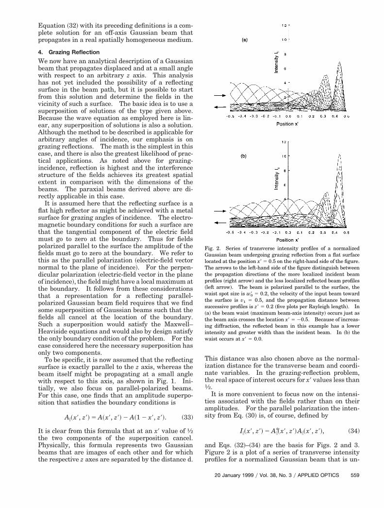
and Eqs. ~32!–~34! are the basis for Figs. 2 and 3.Figure 2 is a plot of a series of transverse intensityprofiles for a normalized Gaussian beam that is un-
Fig. 2. Series of transverse intensity profiles of a normalizedGaussian beam undergoing grazing reflection from a flat surfacelocated at the position x9 5 0.5 on the right-hand side of the figure.
he arrows to the left-hand side of the figure distinguish betweenhe propagation directions of the more localized incident beamrofiles ~right arrow! and the less localized reflected beam profilesleft arrow!. The beam is polarized parallel to the surface, theaist spot size is w90 5 0.2, the velocity of the input beam toward
the surface is v1 5 0.5, and the propagation distance betweenuccessive profiles is z9 5 0.2 ~five plots per Rayleigh length!. In
~a! the beam waist ~maximum beam-axis intensity! occurs just asthe beam axis crosses the location x9 5 20.5. Because of increas-ing diffraction, the reflected beam in this example has a lowerintensity and greater width than the incident beam. In ~b! thewaist occurs at x9 5 0.0.
20 January 1999 y Vol. 38, No. 3 y APPLIED OPTICS 559

t
ia1
5
dergoing grazing reflection from a flat surface locatedat the position x9 5 0.5. The beam in this case ispolarized parallel to the surface, the waist spot size isw90 5 0.2, the velocity of the input beam toward thesurface is v1 5 0.5, and the propagation distancebetween successive profiles is z9 5 0.2 ~five plots perRayleigh length!. This display format shows in acompact way the changes in beam intensity andwidth that occur with propagation, and the arrowsdistinguish the right-traveling incident profiles fromthe left-traveling reflected profiles. As required bythe boundary condition, the intensity goes to zero atthe reflecting surface. In part ~a! the position pa-rameter p1 has the value 20.5, so that the beam waist~maximum beam-axis intensity! occurs just as thebeam axis crosses the location x9 5 20.5. Because ofincreased diffraction, the reflected beam in this ex-ample has a lower intensity and greater width thanthe incident beam. In part ~b! the waist occurs at x95 0.0. A striking feature of the results shown in Fig.2 is the substantial increase in intensity as the beaminteracts with the surface. This increase suggeststhat there could be an enhancement of any nonlinearinteractions between beams if the interaction regionwere in the vicinity of a reflecting surface. Thethickness of the interaction region and the effectivephase velocity can also be controlled by variation ofthe beam orientations. Such adjustments mightprove useful in nonlinear optical applications.
Figure 3 shows a plot of the transverse intensityprofiles of a reflecting Gaussian beam whose waistoccurs at the reflecting surface. The beam is againpolarized parallel to the surface, and the waist spotsize is w90 5 0.2, but in this case the propagationdistance between successive profiles is z9 5 0.1. Inpart ~a! the incident beam moves toward the surfaceat a velocity of v1 5 0.5, and in part ~b! the velocity ofthe beam is v1 5 1.0. Because of the symmetry thatoccurs in this case, the reflected beam has the sameintensity profile as the incident beam. It can be seenfrom these examples that changing the transversevelocity of the incident beam ~or rather its propaga-tion direction with respect to the z axis! changes theinterference structure near the surface. Higher ve-locities ~more nearly normal incidence! leads to thin-ner interference structures.
Similar results are obtained for the intensity of abeam that is polarized perpendicular to the reflectingsurface. Instead of Eq. ~33! the reflection in thiscase can be represented by the alternative superpo-sition
A'~x9, z9! 5 A~x9, z9! 1 A~1 2 x9, z9!. (35)
For this polarization the intensity is defined by
I'~x9, z9! 5 A*'~x9, z9!A'~x9, z9!, (36)
and Eqs. ~32!, ~35!, and ~36! are the basis for Figs. 4and 5. Figure 4 shows a plot of a reflecting beam forwhich the waist spot size is w90 5 0.2, the velocity ofhe input beam toward the surface is v1 5 0.5, and the
propagation distance between successive profiles is z9
60 APPLIED OPTICS y Vol. 38, No. 3 y 20 January 1999
5 0.2. In part ~a! the beam waist occurs as the beamaxis crosses the location x9 5 20.5, and in part ~b! thewaist is at x9 5 0.0. In contrast to Fig. 2, the beamsin Fig. 4 have a maximum of their intensity at thereflecting surface. For the beams in Fig. 5 the waistoccurs at the reflecting surface. The waist spot sizeis w90 5 0.2, and the propagation distance betweensuccessive profiles is z9 5 0.1. In part ~a! the inci-dent beam moves toward the surface at a velocity ofv1 5 0.5, and in part ~b! the velocity of the beam is v15 1.0.
5. Discussion
The high reflectivities that occur when beams areincident at grazing angles have been the basis formany practical applications, particularly in wave-length regions of the spectrum where other highlyreflecting surfaces are not readily available. Earlyapplications occurred in spectroscopy, and curvedsingle-sided waveguides have also been used for
Fig. 3. Transverse intensity profiles of a reflecting Gaussianbeam whose waist occurs at the reflecting surface. The two-headed arrows to the left-hand sides of the figures indicate that inthese cases the incident and reflected beam profiles are identical.The beam is polarized parallel to the surface, the waist spot size isw90 5 0.2, and the propagation distance between successive profiless z9 5 0.1. In ~a! the incident beam is moving toward the surfacet a velocity of v1 5 0.5, and in ~b! the velocity of the beam is v1 5.0.

s05
beam transmission. Recent examples have involvedGaussian beams as the intracavity modes in lasersthat incorporate grazing-incidence mirrors or as thepump beams in laser systems that use grazing-incidence focusing optics. In this study analytic so-lutions of the paraxial wave equation for Gaussianbeams that reflect at grazing angles from a flat sur-face have been obtained.
The results developed here should be useful if onewishes to understand or apply the detailed amplitudeor intensity distribution of a Gaussian beam in thevicinity of a reflecting surface. Of particular inter-est is the much higher intensity that can occur owingto the interference of the incident and the reflectedbeams. A related intensity layer was used previ-ously to provide efficient coupling to the thin gainregion in certain electrode-guided gas lasers. Thislayer has led to enhanced resolution in scanning op-tical microscopy, and it might also be useful in non-linear optics. Depending on the design andorientation of the reflecting surface, one might havecontrol over both the intensity distribution and the
Fig. 4. Transverse intensity profiles of a reflecting Gaussianbeam. The beam is polarized perpendicular to the surface, thewaist spot size is w90 5 0.2, the velocity of the input beam towardthe surface is v1 5 0.5, and the propagation distance betweenuccessive profiles is z9 5 0.2. In ~a! the beam waist occurs as the
beam axis crosses the location x9 5 20.5, and in ~b! the waist is atx9 5 0.0.
phase velocity of the propagating beams near thesurface.
This research was supported in part by the Na-tional Science Foundation under grant PHY94-15583. The author also expresses his appreciationto the members of the Rochester Theory Center forOptical Science and Engineering and the Institute ofOptics at the University of Rochester for valuablediscussions and hospitality during his sabbaticalvisit.
References1. G. D. Boyd and J. P. Gordon, “Confocal multimode resonator
for millimeter through optical wavelength masers,” Bell Sys.Tech. J. 40, 489–508 ~1961!.
2. H. Kogelnik, “Imaging of optical modes—resonators with in-ternal lenses,” Bell Sys. Tech. J. 44, 455–494 ~1965!.
3. H. Kogelnik, “On the propagation of Gaussian beams of lightthrough lenslike media including those with a loss or gainvariation,” Appl. Opt. 4, 1562–1569 ~1965!.
4. L. W. Casperson and S. D. Lunnam, “Gaussian modes in highloss laser resonators,” Appl. Opt. 14, 1193–1199 ~1975!, andreferences therein.
Fig. 5. Transverse intensity profiles of a reflecting Gaussianbeam whose waist occurs at the reflecting surface. The beam ispolarized perpendicular to the surface, the waist spot size is w90 5.2, and the propagation distance between successive profiles is z90.1. In ~a! the incident beam is moving toward the surface at a
velocity of v1 5 0.5, and in ~b! the velocity of the beam is v1 5 1.0.
20 January 1999 y Vol. 38, No. 3 y APPLIED OPTICS 561

5. L. W. Casperson, “Beam modes in complex lenslike media and
1
1
17. K. C. Sun, “Grazing incidence ring resonator for visible wave-
5
resonators,” J. Opt. Soc. Am. 66, 1373–1379 ~1976!.6. A. A. Tovar and L. W. Casperson, “Generalized beam matrices:
Gaussian beam propagation in misaligned complex optical sys-tems,” J. Opt. Soc. Am. 12, 1522–1533 ~1995!.
7. W. S. Bacsa and A. Kulik, “Interference scanning optical probemicroscopy,” Appl. Phys. Lett. 70, 3507–3509 ~1997!.
8. See, for example, J. A. R. Samson, Techniques of VacuumUltraviolet Spectroscopy ~Wiley, New York, 1967!, Section 2.8and references therein.
9. See, for example, A. N. Zaidel and E. Y. Shreider, VacuumUltraviolet Spectroscopy ~Ann Arbor-Humphrey Science Pub-lishers, Inc., Ann Arbor, Mich., 1970!, pp. 119–126.
10. H. Krammer, “Light waves guided by a single curved metallicstrip,” Appl. Opt. 17, 316–319 ~1978!.
11. L. W. Casperson and T. S. Garfield, “Guided beams in concavemetallic waveguides,” IEEE J. Quantum Electron. QE-15,491–496 ~1979!, and references therein.
12. M. E. Marhic, L. I. Kwan, and M. Epstein, “Whispering-galleryCO2 laser,” IEEE J. Quantum Electron. QE-15, 487–490~1979!.
3. J. G. Grossman, L. W. Casperson, and O. M. Stafsudd, “Radio-frequency-excited carbon dioxide metal waveguide laser,”Appl. Opt. 22, 1298–1305 ~1983!.
14. F. S. Al-Mashaabi and L. W. Casperson, “Direct current-excited cw CO2 metal waveguide laser,” Appl. Opt. 28, 1897–1903 ~1989!.
5. J. M. Eggleston, “Angularly stable ring resonators for highpower FELs,” in Proceedings of the International Conference onLasers 1983, R. Powell, ed. ~STS, McLean, Va., 1985!, p. 305.
16. E. Sklar, “The tilt sensitivity of a grazing incidence confocalunstable resonator with applications to free-electron lasers,”IEEE J. Quantum Electron. QE-23, 229–233 ~1987!.
62 APPLIED OPTICS y Vol. 38, No. 3 y 20 January 1999
length free electron laser,” in Optical Resonators, D. A.Holmes, ed., Proc. SPIE 1224, 409–422 ~1990!.
18. D. H. Dowell, M. L. Laucks, A. R. Lowrey, J. L. Adamski, D. J.Pistoresi, D. R. Shoffstall, M. P. Bentz, R. H. Burns, J. Guha,K. C. Sun, W. Tomita, A. H. Lumpkin, S. C. Bender, D. Byrd,and R. L. Tokar, “Tests of a grazing-incidence ring resonatorfree-electron laser,” IEEE J. Quantum Electron. 27, 2613–2625 ~1991!.
19. D. H. Dowell, M. L. Laucks, A. R. Lowrey, J. L. Adamski, D. J.Pistoresi, D. R. Shoffstall, A. H. Lumpkin, S. Bender, D. Byrd,R. L. Tokar, K. Sun, M. Bentz, R. Burns, J. Guha, and W.Tomita, “Final results of the Boeing and Los Alamos grazingincidence ring-resonator free electron laser experiment,” Nucl.Instrum. Methods A 318, 74–80 ~1992!.
20. D. R. Gabardi and D. L. Shealy, “Optical analysis of grazingincidence ring resonators for free-electron lasers,” Opt. Eng.29, 641–648 ~1990!.
21. M. C. Wang, Y. Yuan, and Z. Wang, “The grazing incidencering resonator for a free-electron laser,” Nucl. Instrum. Meth-ods A 318, 874–876 ~1992!.
22. J. P. Braud, “Laser cavities and polarization optics for softX-rays and the extreme ultraviolet,” Appl. Phys. B 50, 205–212~1990!.
23. J. F. Young, J. J. Macklin, and S. E. Harris, “Grazing-incidenceellipsoidal reflector for longitudinally pumping short-wavelength lasers,” Opt. Lett. 12, 90–92 ~1987!.
24. L. W. Casperson, “Gaussian light beams in inhomogeneousmedia,” Appl. Opt. 12, 2434–2441 ~1973!.
25. A. A. Tovar and L. W. Casperson, “Generalized beam matrices:Gaussian beam propagation in misaligned complex optical sys-tems,” J. Opt. Soc. Am. A 12, 1522–1533 ~1995!, Eq. ~24!.