Embed Size (px)
Citation preview
Copyright © 2018 KWP Journals. This is an open access article distributed under the Creative Commons Attribution License,
which permits unrestricted use, distribution, and reproduction in any medium, provided the original work is properly cited.
International Journal of Engineering Works Kambohwell Publisher Enterprises
ISSN: 2409-2770 Vol. 5, Issue 2, PP. 16-20, February 2018
www.kwpublisher.com
Grid Integration of Multistring Photovoltaic Plants with
Modular Multilevel Converter Ahmad Kamal, Dr. Abdul Basit
Abstract—This paper presents the application of Modular Multilevel Converter (MMC) for connecting multistring photovoltaic generation plant. The proposed approach makes it possible for an increased PV plant capacity to be integrated with the grid, while also improving efficiency of conversion and power quality. To increase the efficiency of individual PV module, a DC-DC boost converter is employed with maximum power point tracking (MPPT). The MPPT is implemented by employing Perturb & Observe (P&O) algorithm. The PV modules with DC-DC boost converters are connected in parallel to form a DC bus which is connected to the utility grid with MMC. The MMC inverts the DC bus voltage for interfacing to the grid while maintaining the DC bus voltage constant. The simulation of the overall system in Simulink/MATLAB verifies the validity of the proposed system.
Keywords— Renewable integration, Modular Multilevel
Converter, maximum power point tracking, MPPT,
photovoltaic system
I. INTRODUCTION
The continuously growing demand for energy and depletion of
fossil fuels has increased the need for efficient integration of
renewable resources in the current grid [1]. Solar PV energy
has seen a tremendous increase over the past few years. The
steady reduction in manufacturing cost of PV modules is the
contributing factor towards this growth. This growth is evident
from the fact that in 2013 alone, 30 GW of new PV capacity
was installed. It is encouraging that the PV integration has
increased to more than 100 GW since 2012 [2].
There are basically two main topologies to connect large scale PV systems to the grid: the multistring configuration and the centralized configuration [3, 4]. In the centralized configuration several PV strings are connected in parallel to dc bus. A voltage source converter is used to invert the DC voltage to the grid while also implementing MPPT for all the connected PV strings. The multistring configuration has a similar structure with the centralized configuration with the exception that the PV strings are connected to the DC bus with individual DC-DC boost converters.
The individual DC-DC boost converter perform MPPT for
each PV string exclusively and thus can produce more power than the centralized configuration. The voltage source converter in the centralized configuration also has to tackle the issues of partial shading and panel mismatch increasing its complexity. Owing to these facts the multistring configuration is preferred over the centralized configuration even with the increased initial cost of the DC-DC boost converters.
The increase in PV farms of MW capacity require a
significant increase in the power handling capability of the
grid tied converter. The traditional voltage source converters
with two level topology is incapable of efficiently handling
this higher power flow. Also the grid codes applied on such
PV farms continue to demand efficient integration [5]. The
multilevel converters offer several benefits over the traditional
two-level topology such as higher power and voltage ratings,
lower switching frequency and total harmonic distortion
(THD) [6]. Due to these advantages, multilevel converters are
gaining popularity in many applications such as motor drives,
traction and even in renewable integration [7].
Most of the literature on using multilevel converters for grid interface of PV farms proposes the use of neutral point clamped (NPC) and cascaded H bridge (CHB) based multilevel converters. The studies of [8] and [9] propose a three level neutral point clamped (3L-NPC) multilevel converter with two PV strings. The PV strings are connected without a DC-DC converter with the two DC-link capacitors, enabling MPPT capability for each string. However, the lack of DC-DC boost converter requires several panels to be connected in series for raising the string voltage to be NPC compatible. This series connection of panels introduces the problems of efficient MPPT implementation, partial shading and panel mismatch. Additionally, as the DC-link capacitors have to operate at different MPPT voltages this can cause dc-link unbalance and thus introducing distortions at the grid side. This imbalance of DC-link may also have negative impacts on AC side control of the converter.
The studies of [10] and [11] propose Cascaded H-bridge
(CHB) multilevel converters for this application. The CHB
topology is implemented on a single phase system, due to the
intrinsic power unbalance of each phase. This is not allowed
by the grid codes due to the injection of unbalance currents
into the grid. Additionally, this topology also has the
disadvantages associated with the NPC multilevel converters
discussed above.
This paper presents multistring PV system with three phase modular multilevel converter (MMC). Each PV string is
Ahmad Kamal: Department of Electrical Energy Systems Engineering US-
PCAS-E, UET Peshawar, Paksitan. (e-mail: [email protected])
Dr. Abdul Basit: Department of Electrical Energy Systems Engineering US-PCAS-E, UET Peshawar, Paksitan. (e-mail: [email protected])
International Journal of Engineering Works Vol. 5, Issue 2, PP. 16-20, February 2018
ISSN: 2409-2770
connected to a common DC bus with individual DC-DC boost converters with MPPT capability. The remainder of the paper is divided into four sections. Section II depicts the overall system structure and describes all the three stages that the overall system is divided into. Section III explains the overall control system which is further subdivided into 4 subsections that is: boost stage control, MMC output current control, MMC circulating current control and MMC submodule voltage balance control. The system parameters, simulation and the results are presented in section IV. Finally, the conclusion of the study is presented in section V.
II. OVERALL SYSTEM DESCRIPTION
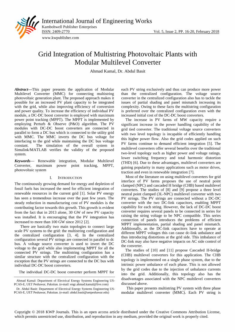
The detailed circuit of the proposed overall system is
illustrated in Figure 1. The system has basically three major
stages: PV string stage, DC-DC boost converter stage and the
grid-tied three phase modular multilevel converter (MMC). It
should be noted that only a single phase of the MMC
converter is displayed in this illustration. The PV strings are
formed by connecting several PV modules in series to raise
the voltage level to the desired level. For connecting the PV
string to DC bus any topology of the DC-DC boost converter
can be used according to specific requirements. In this study,
the typical boost converter topology is used due to simplicity
and ease of simulation.
Figure 1. Proposed system configuration
Modular multilevel converter is a relatively newer topology
of multilevel converters for medium to high voltage
applications. Modular multilevel converter has many
advantages compared with the traditional multilevel
converters such as: minimizing the total harmonic distortion
(THD) on output voltage, operating with lower switching
frequency, low dv/dt thus lower stresses on power switches
and operating with any voltage level.
The basic building block of the MMC is a submodule. It is
essentially a half bridge inverter with capacitor as shown in
Figure 1. The half bridge can be constituted with any power
switch such as IGBT, IGCT or MOSFET with antiparallel
diode, according to specific requirements. The two switches of
the submodule operate in a complimentary fashion. When
switch S2 of the submodule is turned-on the submodule
capacitor voltage becomes the output voltage of the
submodule. When S1 is turned-on the submodule is essentially
turned-off, or in the case of MMC referred to as being
bypassed. When N number of submodules are connected in
series it forms an ‘arm’ of the MMC as shown in Figure 1.
Two arms combine together to form the individual phase,
called the ‘leg’ of the MMC.
The number of output voltage levels generated by the MMC
can be with either N+1 or 2N+1 depending on the modulation
strategy used. The three main modulation strategies used for
MMC are the pulse width modulation (PWM), space vector
modulation and the nearest level modulation. The modulation
strategy used in this study is the carrier phase shifted PWM.
The benefit of using the modular multilevel converter is the modularity of the system which means that the system can be scaled from small KW level to large MW level PV systems.
III. CONTROL SYSTEM
Decoupling MPPT control from the grid converter makes it
possible to design and implement control for DC-DC boost
converter and MMC independently.
A. DC-DC Boost Converter Control
The main control objective of the DC-DC boost converter is
to implement the MPPT algorithm for the PV string while
stepping up the string voltage.
The controllable variable of the DC-DC boost converter is
the inductor current. This inductor current can control either
the input voltage or the output voltage of the DC-DC boost
converter. As the output voltage of the converter, that is the
DC bus voltage, is controlled by the grid-tied MMC so the
boost converter controls the input voltage. The input voltage
of the DC-DC boost converter in continuous conduction mode
is given by the following equation.
𝑉𝑖𝑛 = 𝑉𝑜𝑢𝑡 (1− 𝐷) (1)
As Vout is controlled by the MMC, changing the duty cycle D of the converter changes the input voltage Vin, which is essentially the PV string voltage. Figure 2 shows the control structure of the DC-DC boost converter.
Figure 2. Boost converter control with MPPT
The MPPT algorithm used in this study is the well-known Perturb and Observe (P&O) algorithm. The output of the control structure ‘Pulses’ are the pulses that drive the power switch of the boost converter. The flowchart for the Perturb and Observe (P&O) MPPT algorithm is depicted in Figure 3.

International Journal of Engineering Works Vol. 5, Issue 2, PP. 16-20, February 2018
ISSN: 2409-2770
Figure 3. Perturb and Observe (P&O) MPPT flowchart
B. MMC Output Current Control
The control scheme for output current control of MMC is
similar to that of two level converters control in dq rotating
reference frame [12]. The control system is divided into two
control loops: inner control loop and outer control loop. The
outer control loop controls the DC bus voltage by generating
reference signal for d-axis current. The relationship between
DC bus voltage Vdc and d-axis current id can be derived from
AC side and DC side power balance of MMC, given as:
𝑃 =
3
2𝑉𝑑 𝑖𝑑 = 𝑉𝑑𝑐 𝑖𝑑𝑐 (2)
𝑖𝑑𝑐 = 𝐶
𝑑𝑉𝑑𝑐
𝑑𝑡 (3)
Transferring to s domain and combining (2) and (3) the
system transfer function is given as:
𝑉𝑑𝑐 𝑠
𝑖𝑑 𝑠 =
3𝑉𝑑
2𝑉𝑑𝑐 ,𝑟𝑒𝑓
.1
𝑠𝐶 (4)
The above system transfer function is used to derive the
control system for DC voltage control, shown in Figure 4.
Figure 4. DC voltage control loop
The inner control structure can be deduced from the
dynamic equations of the MMC, given as:
𝐿𝑠
𝑑𝑖𝑗
𝑑𝑡= −𝑅𝑠𝑖𝑔 + 𝑉𝑔 − 𝑉𝑡 (5)
The above dynamic equation in the dq-frame is given as:
𝐿𝑠
𝑑𝑖𝑑𝑑𝑡
= −𝑅𝑠𝑖𝑑 + 𝑉𝑔𝑑 − 𝑉𝑡𝑑 + 𝜔𝐿𝑖𝑞 (6a)
𝐿𝑠
𝑑𝑖𝑞
𝑑𝑡= −𝑅𝑠𝑖𝑞 + 𝑉𝑔𝑞 − 𝑉𝑡𝑑 − 𝜔𝐿𝑖𝑑
(6b)
In the above equations, Vtd , Vtq , id , iq , Vgd , Vgq , 𝜔Lid ,
𝜔Liq are d and q axis components of MMC output voltage,
output current, grid voltage and coupling terms respectively.
Based on the above equations, the architecture of the inner
current control loop is derived as in Figure 5.
Figure 5. Inner current control loop
C. MMC Circulating Current Control
The floating nature of the submodule capacitors results in a
circulating current that flows from the DC bus to the MMC
and between different phases of MMC. The harmonic
components of the circulating current does not contribute in
power transfer but increases power losses and current rating of
electrical components. Therefore, the major component of the
harmonic components, the second harmonic component, is
controlled to zero. This circulating current can be represented
by the following equation:
𝑖𝑐𝑐 ,𝑗 =
𝑖𝑢𝑗 + 𝑖𝑙𝑗
2−
𝐼𝑑𝑐3
(7)
Substituting the above equation in dq-frame in the dynamic
equations of the MMC gives the following relationship:
𝑉𝑐𝑐 ,𝑑 = 𝑅𝑎𝑟𝑚 𝑖𝑐𝑐 ,𝑑 + 𝐿𝑎𝑟𝑚 𝑖𝑐𝑐 ,𝑑 + 2𝐿𝑎𝑟𝑚 𝜔𝑖𝑐𝑐 ,𝑞 (8a)
𝑉𝑐𝑐 ,𝑞 = 𝑅𝑎𝑟𝑚 𝑖𝑐𝑐 ,𝑞 + 𝐿𝑎𝑟𝑚 𝑖𝑐𝑐 ,𝑞 − 2𝐿𝑎𝑟𝑚 𝜔𝑖𝑐𝑐 ,𝑑 (8b)
Considering the above equations, it is evident that the
circulating current can be controlled directly by 𝑉𝑐𝑐 ,𝑑 and 𝑉𝑐𝑐 ,𝑞
as shown in Figure 6. The output of this circulating current
controller will be subtracted from both lower and upper arm
voltage references genareted by inner current loop.
Figure 6. Circulaing current control loop
D. MMC Submodule Voltage Balancing Control
The floating nature of the submodule capacitors has the
adverse impact that the capacitor voltages diverge with time.
This divergence if not kept small or preferably negligible can
collapse the entire system. Therefore, to keep the submodule
voltages equal an active balancing algorithm is required.
The most widely used method for this purpose is the sorting
method [13]. Generally, the number of submodules to be
inserted in each arm is known after modulation. The decision
International Journal of Engineering Works Vol. 5, Issue 2, PP. 16-20, February 2018
ISSN: 2409-2770
of which submodules to insert or bypass, to balance the
submodule voltages, is taken by the sorting algorithm. The
algorithm first measures and sorts all the submodules
capacitor voltages. Submodules with the lowest voltages are
inserted to be charged if the arm current is positive. Whereas,
submodules with the highest voltages are inserted to be
discharged if the arm current is negative. However, bypassing
the submodule keeps its voltage unchanged.
IV. SIMULATION & RESUTLS
The whole system with the control schemes was simulated
in Simulink/MATLAB. Since the simulation used detail
models of all the converters, and the system was simulated
with different temperature and irradiation levels, only four PV
string with individual boost converters were used. The panels
used in the simulation were SunPower SPR-315E-WHT-D
rated at 315W, with output current of 5.76A and 54.7V output
voltage at MPP at STC (radiation of 1000Wm2 and panel
temperature of 25°C). A single PV array is built with 64
modules in series per string and 5 strings in parallel. The DC-
DC boost converter stage steps up the voltage of the PV array
to 500V of the DC bus voltage. As the DC bus voltage is 500V
the number of submodules per arm are selected to be 6. This is
considering the voltage rating of the submodule is to be kept at
100V, which makes it possible to use a wide variety of power
switches. The system parameters used for the simulation are
summarized in Table 1.
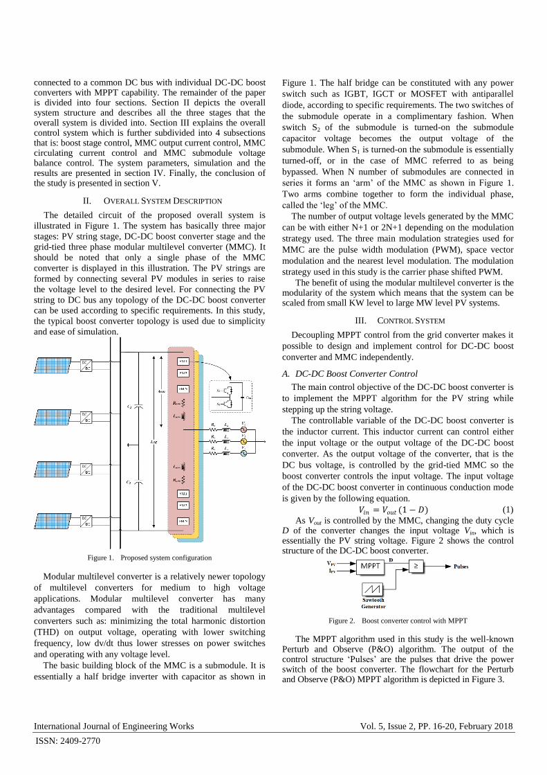
The MPPT performance is evaluated with different levels of
irradiance and ambient temperature as shown in Figure 7. The
resulting varying duty ratio, array voltage and power is
depicted in the same figure. To validate the performance of the
DC bus voltage control of the MMC, the irradiance level of all
the converters connected with the DC bus are varied as shown
in Figure 8. It can be seen that the varying irradiance level
changes the combined power output of all the PV modules but
the DC bus voltage stays relatively unchanged.
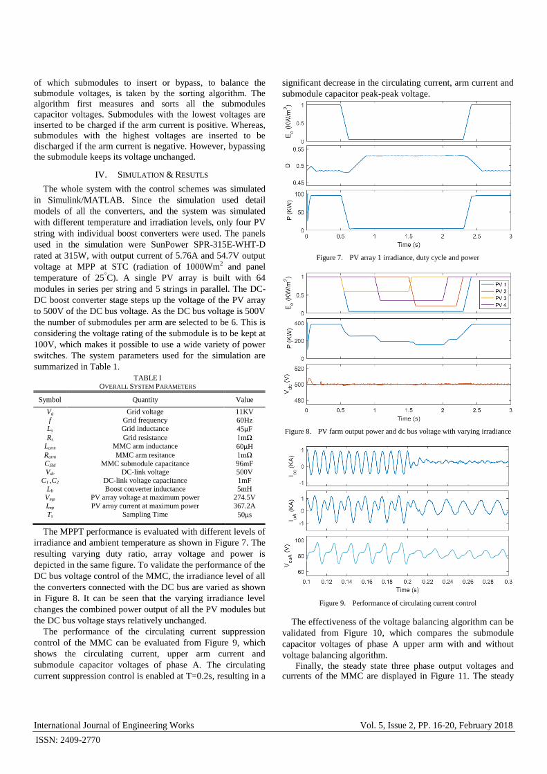
The performance of the circulating current suppression
control of the MMC can be evaluated from Figure 9, which
shows the circulating current, upper arm current and
submodule capacitor voltages of phase A. The circulating
current suppression control is enabled at T=0.2s, resulting in a
significant decrease in the circulating current, arm current and
submodule capacitor peak-peak voltage.
Figure 7. PV array 1 irradiance, duty cycle and power
Figure 8. PV farm output power and dc bus voltage with varying irradiance
Figure 9. Performance of circulating current control
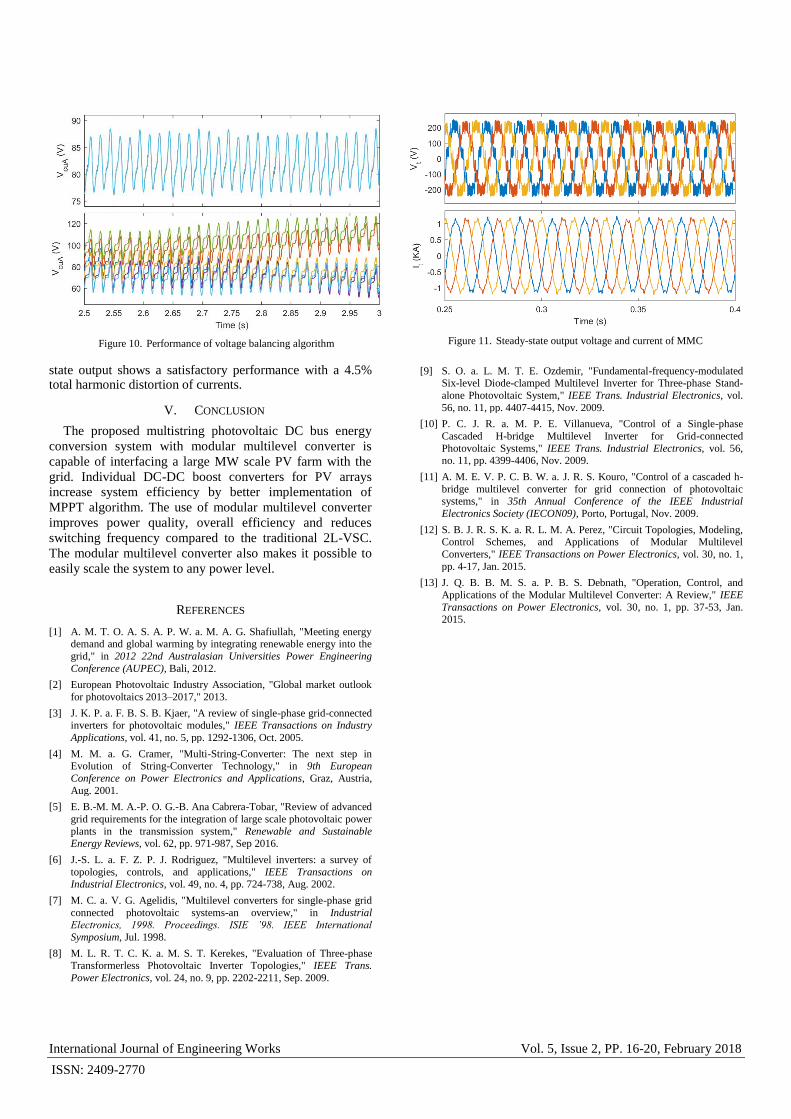
The effectiveness of the voltage balancing algorithm can be
validated from Figure 10, which compares the submodule
capacitor voltages of phase A upper arm with and without
voltage balancing algorithm.
Finally, the steady state three phase output voltages and currents of the MMC are displayed in Figure 11. The steady
TABLE I OVERALL SYSTEM PARAMETERS
Symbol Quantity Value
Vg Grid voltage 11KV
f Grid frequency 60Hz Ls Grid inductance 45µF
Rs Grid resistance 1mΩ
Larm MMC arm inductance 60µH
Rarm MMC arm resitance 1mΩ
CSM MMC submodule capacitance 96mF Vdc DC-link voltage 500V
C1 ,C2 DC-link voltage capacitance 1mF
Lb Boost converter inductance 5mH Vmp PV array voltage at maximum power 274.5V
Imp PV array current at maximum power 367.2A
Ts Sampling Time 50µs
International Journal of Engineering Works Vol. 5, Issue 2, PP. 16-20, February 2018
ISSN: 2409-2770
Figure 10. Performance of voltage balancing algorithm
Figure 11. Steady-state output voltage and current of MMC
state output shows a satisfactory performance with a 4.5% total harmonic distortion of currents.
V. CONCLUSION
The proposed multistring photovoltaic DC bus energy
conversion system with modular multilevel converter is
capable of interfacing a large MW scale PV farm with the
grid. Individual DC-DC boost converters for PV arrays
increase system efficiency by better implementation of
MPPT algorithm. The use of modular multilevel converter
improves power quality, overall efficiency and reduces
switching frequency compared to the traditional 2L-VSC.
The modular multilevel converter also makes it possible to
easily scale the system to any power level.
REFERENCES
[1] A. M. T. O. A. S. A. P. W. a. M. A. G. Shafiullah, "Meeting energy demand and global warming by integrating renewable energy into the
grid," in 2012 22nd Australasian Universities Power Engineering
Conference (AUPEC), Bali, 2012.
[2] European Photovoltaic Industry Association, "Global market outlook
for photovoltaics 2013–2017," 2013.
[3] J. K. P. a. F. B. S. B. Kjaer, "A review of single-phase grid-connected inverters for photovoltaic modules," IEEE Transactions on Industry
Applications, vol. 41, no. 5, pp. 1292-1306, Oct. 2005.
[4] M. M. a. G. Cramer, "Multi-String-Converter: The next step in Evolution of String-Converter Technology," in 9th European
Conference on Power Electronics and Applications, Graz, Austria,
Aug. 2001.
[5] E. B.-M. M. A.-P. O. G.-B. Ana Cabrera-Tobar, "Review of advanced
grid requirements for the integration of large scale photovoltaic power
plants in the transmission system," Renewable and Sustainable Energy Reviews, vol. 62, pp. 971-987, Sep 2016.
[6] J.-S. L. a. F. Z. P. J. Rodriguez, "Multilevel inverters: a survey of
topologies, controls, and applications," IEEE Transactions on Industrial Electronics, vol. 49, no. 4, pp. 724-738, Aug. 2002.
[7] M. C. a. V. G. Agelidis, "Multilevel converters for single-phase grid
connected photovoltaic systems-an overview," in Industrial Electronics, 1998. Proceedings. ISIE ’98. IEEE International
Symposium, Jul. 1998.
[8] M. L. R. T. C. K. a. M. S. T. Kerekes, "Evaluation of Three-phase Transformerless Photovoltaic Inverter Topologies," IEEE Trans.
Power Electronics, vol. 24, no. 9, pp. 2202-2211, Sep. 2009.
[9] S. O. a. L. M. T. E. Ozdemir, "Fundamental-frequency-modulated Six-level Diode-clamped Multilevel Inverter for Three-phase Stand-
alone Photovoltaic System," IEEE Trans. Industrial Electronics, vol.
56, no. 11, pp. 4407-4415, Nov. 2009.
[10] P. C. J. R. a. M. P. E. Villanueva, "Control of a Single-phase
Cascaded H-bridge Multilevel Inverter for Grid-connected
Photovoltaic Systems," IEEE Trans. Industrial Electronics, vol. 56, no. 11, pp. 4399-4406, Nov. 2009.
[11] A. M. E. V. P. C. B. W. a. J. R. S. Kouro, "Control of a cascaded h-
bridge multilevel converter for grid connection of photovoltaic systems," in 35th Annual Conference of the IEEE Industrial
Electronics Society (IECON09), Porto, Portugal, Nov. 2009.
[12] S. B. J. R. S. K. a. R. L. M. A. Perez, "Circuit Topologies, Modeling, Control Schemes, and Applications of Modular Multilevel
Converters," IEEE Transactions on Power Electronics, vol. 30, no. 1,
pp. 4-17, Jan. 2015.
[13] J. Q. B. B. M. S. a. P. B. S. Debnath, "Operation, Control, and
Applications of the Modular Multilevel Converter: A Review," IEEE
Transactions on Power Electronics, vol. 30, no. 1, pp. 37-53, Jan. 2015.
![Modular Cascaded H-Bridge Multilevel Photovoltaic …ijlemr.com/papers/REETA2K16/EE005.pdf · efficiency when compared to other converter topologies [17]. ... To show the necessity](https://img.pdfslide.net/doc/110x75/5b04bf6c7f8b9a0a548e0993/modular-cascaded-h-bridge-multilevel-photovoltaic-when-compared-to-other-converter.jpg)