Embed Size (px)
Citation preview

BULLETIN OF THE POLISH ACADEMY OF SCIENCES
TECHNICAL SCIENCES, Vol. 59, No. 4, 2011
DOI: 10.2478/v10175-011-0060-8
POWER ELECTRONICS
Grid synchronization and symmetrical components extraction
with PLL algorithm for grid connected power electronic converters
– a review
M. BOBROWSKA-RAFAL∗, K. RAFAL, M. JASINSKI, and M.P. KAZMIERKOWSKI
Institute of Control and Industrial Electronics, Warsaw University of Technology, 75 Koszykowa St., 00-662 Warsaw, Poland
Abstract. In this paper, a review of Phase Locked Loop (PLL) algorithms and symmetrical component extraction methods intended for
grid-connected power electronic converters are presented. Proposed classification is based on voltage representation in three coordinates:
natural (abc), stationary (αβ) and rotating coordinates (dq). The three selected algorithms are described in details: Dual Second Order
Generalized Integrator (DSOGI-PLL), Dual Virtual Flux – both in stationary coordinates. The third one, in rotating dq coordinates, is Dual
Synchronous Reference Frame PLL (DSRF-PLL). A comparison of PLL algorithms is presented. Also, selected experimental results are
given to verify practical application of discussed algorithms.
Key words: Phase Locked Loop (PLL), symmetrical component extraction, grid synchronization, grid-connected converter, smart grid,
Renewable Energy Sources (RES), voltage dip, higher harmonics, power quality.
1. Introduction
Electrical grid is always struggling with problem of voltage
disturbances. Recently, this issue has became substantially se-
vere, as the conventional electrical infrastructure is extending.
Revolution of electrical system has been proceeding since in-
troduction of Distributed Generation (DG) [1] and Renew-
able Energy Sources (RES) to the electrical grid. Integration
of different technologies leads to increasing diversity of grid,
including smart grids, and forces more restrictive standards.
Restrictions for RES and DG power quality are given in each
country in so called “grid codes”. Among grid requirements
for RES there are: operation with certain power factor (close
to unity), limited harmonic content of injected current, con-
tinuous operation under voltage distortions, etc. Most of these
requirements can be satisfied with proper control of grid con-
nected converter [2–4]. Therefore, RES use power electronic
converters to adapt generated power parameters to those re-
quired by electrical grid.
On the other hand, many of power electronic devices are
introduced to the grid specially to compensate for decreasing
power quality. Most of installations are ordered by industrial
customers to protect against voltage dips, higher harmonics or
flicker and constitute group called CUPS (Custom Power Sys-
tems). The CUPS includes devices like: DVR, D-STATCOM,
UPS and others. There are also devices installed for trans-
mission system support, called FACTS (Flexible AC Trans-
mission Systems), like: STATCOM, SVC, SSSC, UPFC and
others [5, 6].
Every of above mentioned grid-connected device has to
be precisely synchronized with grid voltage. It is significant
due to generating high quality energy by RES as well as com-
pensating energy by CUPS or FACTS [7]. It is essential also
for different kinds of load, which without synchronization, in-
troduce distortions to grid voltage. Therefore, accurate phase
angle information of grid voltage is indispensable for proper
operation of every grid-connected power converter. Table 1
contains different grid-connected devices with necessary grid
synchronization, cooperating with power converters.
Table 1
Grid-connected devices, employing power converters with grid
synchronization
Group of devices Applications
Renewable Energy
Sources (RES)
wind power plants, photovoltaic plants,
wave energy plants, etc.
Custom Power Systems
(CUPS)
Uninterruptible Power Supply (UPS), Ac-
tive Power Filter (APF), Dynamic Voltage
Restorer (DVR), D-STATCOM, etc.
Flexible AC
Transmission Systems
(FACTS)
Static Compensator (STATCOM), Static
Var Compensator (SVC), Static Series Syn-
chronous Compensator (SSSC), etc.
Loads DC loads cooperating with grid-connected
converters (AC/DC), AC loads with
AC/DC/AC converters, for ex. active front
end (AFE) in adjustable speed drives
(ASD).
In order to obtain synchronization Phase Locked Loop
(PLL) is implemented to control algorithm of grid-connected
converter. The objective of PLL’s is calculation of stable and
undisturbed phase angle of grid during any voltage conditions,
especially including distorted voltage.
A variety of PLL structures are described in literature
but there is no clear classification. This paper presents plain
division based on coordinates in which PLL operates. The
∗e-mail: [email protected]
485
M. Bobrowska-Rafal, K. Rafal, M. Jasinski, and M.P. Kazmierkowski
classification focuses only on three-phase applications aimed
for digital implementation on DSP platform.
In this article three best promising PLL algorithms are
described. The selection is based on previous reviews [8–12]
and authors’ deep research. Moreover, in this paper evaluation
criterions are proposed to verify the best operating algorithm.
In simulation process three chosen algorithms were verified
due to selected criterions. The results of analysis are summa-
rized in conclusions.
2. Application and structure
The PLL structure is a feedback algorithm, which automat-
ically adjusts the phase of locally generated signal to match
the phase of an input signal. Basic concept was presented by
Bellescise in 1932 [13] and it was widely used in radio com-
munication. In grid-connected converter applications, PLL is
crucial for control algorithm performance. Among common
tasks, where PLL is used are:
• Active and reactive power control;
• Voltage regulation, dips and flicker compensation;
• Grid monitoring: fault detection by angle/frequency detec-
tion, power factor calculation;
• Smart grid control: islanding detection, connect-
ing/disconnecting process control, fault ride through;
• Current control: higher harmonics and reactive power com-
pensation;
• others.
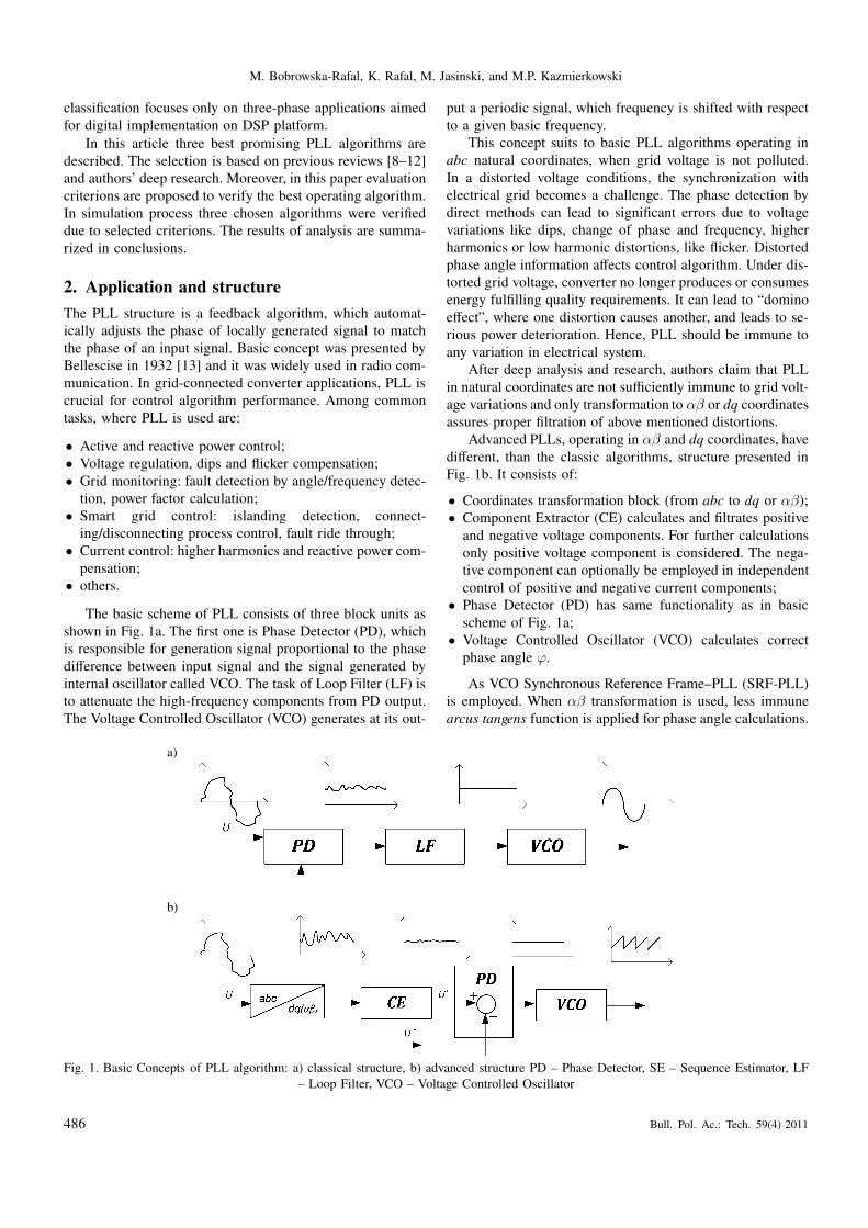
The basic scheme of PLL consists of three block units as
shown in Fig. 1a. The first one is Phase Detector (PD), which
is responsible for generation signal proportional to the phase
difference between input signal and the signal generated by
internal oscillator called VCO. The task of Loop Filter (LF) is
to attenuate the high-frequency components from PD output.
The Voltage Controlled Oscillator (VCO) generates at its out-
put a periodic signal, which frequency is shifted with respect
to a given basic frequency.
This concept suits to basic PLL algorithms operating in
abc natural coordinates, when grid voltage is not polluted.
In a distorted voltage conditions, the synchronization with
electrical grid becomes a challenge. The phase detection by
direct methods can lead to significant errors due to voltage
variations like dips, change of phase and frequency, higher
harmonics or low harmonic distortions, like flicker. Distorted
phase angle information affects control algorithm. Under dis-
torted grid voltage, converter no longer produces or consumes
energy fulfilling quality requirements. It can lead to “domino
effect”, where one distortion causes another, and leads to se-
rious power deterioration. Hence, PLL should be immune to
any variation in electrical system.
After deep analysis and research, authors claim that PLL
in natural coordinates are not sufficiently immune to grid volt-
age variations and only transformation to αβ or dq coordinates
assures proper filtration of above mentioned distortions.
Advanced PLLs, operating in αβ and dq coordinates, have
different, than the classic algorithms, structure presented in
Fig. 1b. It consists of:
• Coordinates transformation block (from abc to dq or αβ);
• Component Extractor (CE) calculates and filtrates positive
and negative voltage components. For further calculations
only positive voltage component is considered. The nega-
tive component can optionally be employed in independent
control of positive and negative current components;
• Phase Detector (PD) has same functionality as in basic
scheme of Fig. 1a;
• Voltage Controlled Oscillator (VCO) calculates correct
phase angle ϕ.
As VCO Synchronous Reference Frame–PLL (SRF-PLL)
is employed. When αβ transformation is used, less immune
arcus tangens function is applied for phase angle calculations.
a)
b)
Fig. 1. Basic Concepts of PLL algorithm: a) classical structure, b) advanced structure PD – Phase Detector, SE – Sequence Estimator, LF
– Loop Filter, VCO – Voltage Controlled Oscillator
486 Bull. Pol. Ac.: Tech. 59(4) 2011
Grid synchronization and symmetrical components extraction with PLL algorithm...
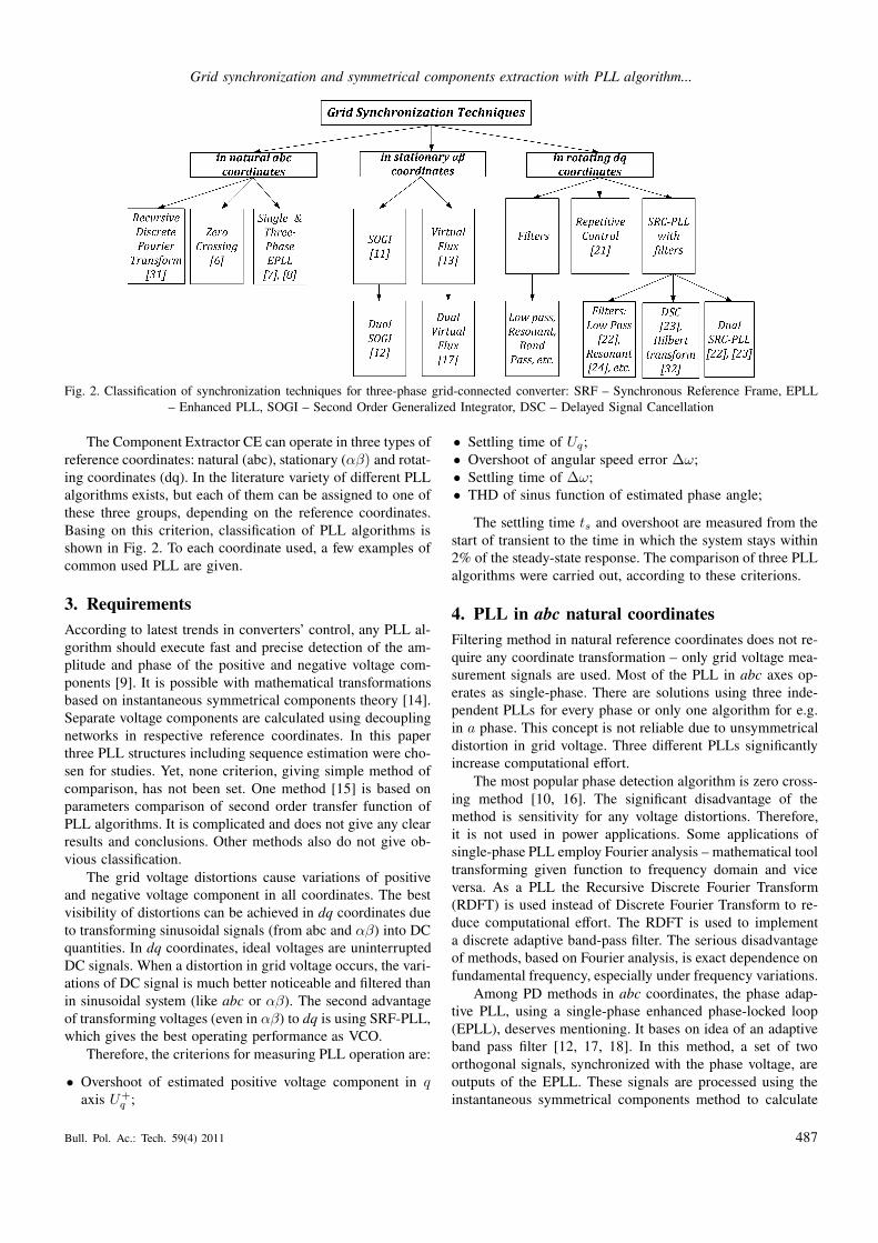
Fig. 2. Classification of synchronization techniques for three-phase grid-connected converter: SRF – Synchronous Reference Frame, EPLL
– Enhanced PLL, SOGI – Second Order Generalized Integrator, DSC – Delayed Signal Cancellation
The Component Extractor CE can operate in three types of
reference coordinates: natural (abc), stationary (αβ) and rotat-
ing coordinates (dq). In the literature variety of different PLL
algorithms exists, but each of them can be assigned to one of
these three groups, depending on the reference coordinates.
Basing on this criterion, classification of PLL algorithms is
shown in Fig. 2. To each coordinate used, a few examples of
common used PLL are given.
3. Requirements
According to latest trends in converters’ control, any PLL al-
gorithm should execute fast and precise detection of the am-
plitude and phase of the positive and negative voltage com-
ponents [9]. It is possible with mathematical transformations
based on instantaneous symmetrical components theory [14].
Separate voltage components are calculated using decoupling
networks in respective reference coordinates. In this paper
three PLL structures including sequence estimation were cho-
sen for studies. Yet, none criterion, giving simple method of
comparison, has not been set. One method [15] is based on
parameters comparison of second order transfer function of
PLL algorithms. It is complicated and does not give any clear
results and conclusions. Other methods also do not give ob-
vious classification.
The grid voltage distortions cause variations of positive
and negative voltage component in all coordinates. The best
visibility of distortions can be achieved in dq coordinates due
to transforming sinusoidal signals (from abc and αβ) into DC
quantities. In dq coordinates, ideal voltages are uninterrupted
DC signals. When a distortion in grid voltage occurs, the vari-
ations of DC signal is much better noticeable and filtered than
in sinusoidal system (like abc or αβ). The second advantage
of transforming voltages (even in αβ) to dq is using SRF-PLL,
which gives the best operating performance as VCO.
Therefore, the criterions for measuring PLL operation are:
• Overshoot of estimated positive voltage component in qaxis U+
q ;
• Settling time of Uq;
• Overshoot of angular speed error ∆ω;
• Settling time of ∆ω;
• THD of sinus function of estimated phase angle;
The settling time ts and overshoot are measured from the
start of transient to the time in which the system stays within
2% of the steady-state response. The comparison of three PLL
algorithms were carried out, according to these criterions.
4. PLL in abc natural coordinates
Filtering method in natural reference coordinates does not re-
quire any coordinate transformation – only grid voltage mea-
surement signals are used. Most of the PLL in abc axes op-
erates as single-phase. There are solutions using three inde-
pendent PLLs for every phase or only one algorithm for e.g.
in a phase. This concept is not reliable due to unsymmetrical
distortion in grid voltage. Three different PLLs significantly
increase computational effort.
The most popular phase detection algorithm is zero cross-
ing method [10, 16]. The significant disadvantage of the
method is sensitivity for any voltage distortions. Therefore,
it is not used in power applications. Some applications of
single-phase PLL employ Fourier analysis – mathematical tool
transforming given function to frequency domain and vice
versa. As a PLL the Recursive Discrete Fourier Transform
(RDFT) is used instead of Discrete Fourier Transform to re-
duce computational effort. The RDFT is used to implement
a discrete adaptive band-pass filter. The serious disadvantage
of methods, based on Fourier analysis, is exact dependence on
fundamental frequency, especially under frequency variations.
Among PD methods in abc coordinates, the phase adap-
tive PLL, using a single-phase enhanced phase-locked loop
(EPLL), deserves mentioning. It bases on idea of an adaptive
band pass filter [12, 17, 18]. In this method, a set of two
orthogonal signals, synchronized with the phase voltage, are
outputs of the EPLL. These signals are processed using the
instantaneous symmetrical components method to calculate
Bull. Pol. Ac.: Tech. 59(4) 2011 487
M. Bobrowska-Rafal, K. Rafal, M. Jasinski, and M.P. Kazmierkowski
the positive sequence component of the grid voltage. Among
disadvantages of the EPLL there are high complexity and low
dynamics.
Other concept bases on representation of single phase sig-
nal as an virtual vector and use of PLL operating in station-
ary coordinates. However, it requires generation of orthogonal
component – so called quadrature signal generation, there-
fore is characterized by delay. Among them are Delay Signal
Cancelation (DSC) [19], described below or Hilbert Trans-
form [20].
5. PLL in dq synchronous rotating coordinates
In the PLL algorithm operating in dq rotating coordinates,
voltage signals are transformed to Synchronous Rotation
Frame (SRF), where in ideal conditions three-phase sinusoidal
voltages become two DC signals. The basic solution of PLL
in SRF, called SRF-PLL, is presented in Fig. 3 [21]. It is
based on PI controller, widely used in almost all control algo-
rithms for converters, for example in Voltage Oriented Control
(VOC) [2, 3]. The PI controller adjusts estimated frequency,
by controlling Uq to be zero, so that d-axis follows grid volt-
age vector. Signal of integrated frequency represents phase
angle ϕ∗ and is used for coordinates transformation.
Any distortion of grid voltage is seen as a disturbance
in SRF, particularly negative voltage sequence becomes 2nd
harmonic component. It causes variation of estimated phase
angle resulting in improper coordinates transformation.
One of basic solution for this problem is SRF-PLL with
LPF. However, the dynamic is slow and phase shift is intro-
duced to signal. The second is resonant filters [22], which
is also slow but is immune to higher harmonics and does
not lead in phase shift. Less common technique for PLL is
Moving Average Filter, which performance is similar to LPF
[23]. Repetitive controller operates like band-pass filter and
improves elimination of higher harmonics. It filters out odd
harmonics and even are left. Repetitive controller presented in
[24] is immune to 2nd harmonic as well. Delayed Signal Can-
celation (DSC) is a filtering method, based on combination of
time delayed synchronous coordinates magnitudes [19, 25]. To
eliminate negative sequence, which appears as 2nd harmonic
oscillation, the output of DSC filter is a sum of voltage in d
or q axis and the same voltage delayed by quarter of period.
There are also PLLs’ method based on predictive filters and
moving average filters [26], phasors estimation [27] or lead
filter (lead SRF-PLL) [28].
Fig. 3. Concept of Synchronous Reference Frame PLL (SRF-PLL)
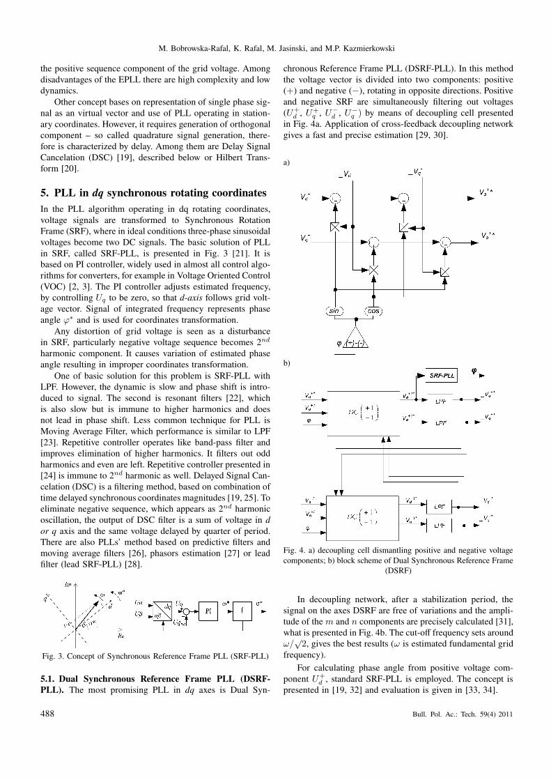
5.1. Dual Synchronous Reference Frame PLL (DSRF-
PLL). The most promising PLL in dq axes is Dual Syn-
chronous Reference Frame PLL (DSRF-PLL). In this method
the voltage vector is divided into two components: positive
(+) and negative (−), rotating in opposite directions. Positive
and negative SRF are simultaneously filtering out voltages
(U+
d , U+q , U−
d , U−
q ) by means of decoupling cell presented
in Fig. 4a. Application of cross-feedback decoupling network
gives a fast and precise estimation [29, 30].
a)
b)
Fig. 4. a) decoupling cell dismantling positive and negative voltage
components; b) block scheme of Dual Synchronous Reference Frame
(DSRF)
In decoupling network, after a stabilization period, the
signal on the axes DSRF are free of variations and the ampli-
tude of the m and n components are precisely calculated [31],
what is presented in Fig. 4b. The cut-off frequency sets around
ω/√
2, gives the best results (ω is estimated fundamental grid
frequency).
For calculating phase angle from positive voltage com-
ponent U+
d , standard SRF-PLL is employed. The concept is
presented in [19, 32] and evaluation is given in [33, 34].
488 Bull. Pol. Ac.: Tech. 59(4) 2011
Grid synchronization and symmetrical components extraction with PLL algorithm...
6. PLL in αβ stationary reference coordinates
Representation of three-phase voltage as a complex vector
in αβ plane allows to use simple arcus tangens function for
phase extraction. As this methods operates without any fil-
ters, it instantaneously responds to any kind of distortion in
grid voltage. Hence, the angle calculated by arcus tangens is
often a reference for content of distortions. Many solutions
for distortion rejection in αβ were proposed: filters basing
on notch, vector or low pass filters, which effectiveness is not
satisfactory [35, 36], as well as band-pass or delay filters [37].
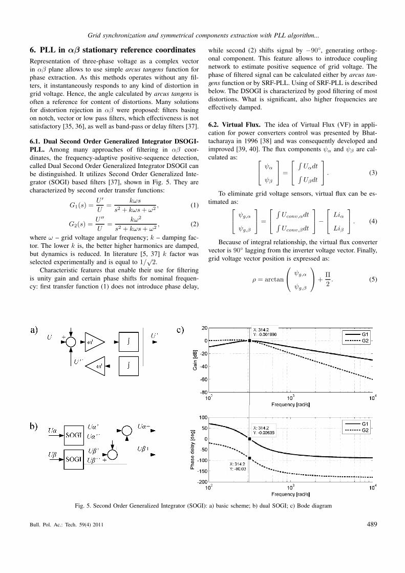
6.1. Dual Second Order Generalized Integrator DSOGI-
PLL. Among many approaches of filtering in αβ coor-
dinates, the frequency-adaptive positive-sequence detection,
called Dual Second Order Generalized Integrator DSOGI can
be distinguished. It utilizes Second Order Generalized Inte-
grator (SOGI) based filters [37], shown in Fig. 5. They are
characterized by second order transfer functions:
G1(s) =U ′
U=
kωs
s2 + kωs+ ω2, (1)
G2(s) =U ′′
U=
kω2
s2 + kωs+ ω2, (2)
where ω – grid voltage angular frequency; k – damping fac-
tor. The lower k is, the better higher harmonics are damped,
but dynamics is reduced. In literature [5, 37] k factor was
selected experimentally and is equal to 1/√
2.
Characteristic features that enable their use for filtering
is unity gain and certain phase shifts for nominal frequen-
cy: first transfer function (1) does not introduce phase delay,
while second (2) shifts signal by −90◦, generating orthog-
onal component. This feature allows to introduce coupling
network to estimate positive sequence of grid voltage. The
phase of filtered signal can be calculated either by arcus tan-
gens function or by SRF-PLL. Using of SRF-PLL is described
below. The DSOGI is characterized by good filtering of most
distortions. What is significant, also higher frequencies are
effectively damped.
6.2. Virtual Flux. The idea of Virtual Flux (VF) in appli-
cation for power converters control was presented by Bhat-
tacharaya in 1996 [38] and was consequently developed and
improved [39, 40]. The flux components ψα and ψβ are cal-
culated as:
ψα
ψβ
=
∫
Uαdt∫
Uβdt
. (3)
To eliminate grid voltage sensors, virtual flux can be es-
timated as:
ψg,α
ψg,β
=
∫
Uconv,αdt∫
Uconv,βdt
−
Liα
Liβ
. (4)
Because of integral relationship, the virtual flux converter
vector is 90◦ lagging from the inverter voltage vector. Finally,
grid voltage vector position is expressed as:
ρ = arctan
ψg,α
ψg,β
+Π
2. (5)
Fig. 5. Second Order Generalized Integrator (SOGI): a) basic scheme; b) dual SOGI; c) Bode diagram
Bull. Pol. Ac.: Tech. 59(4) 2011 489
M. Bobrowska-Rafal, K. Rafal, M. Jasinski, and M.P. Kazmierkowski
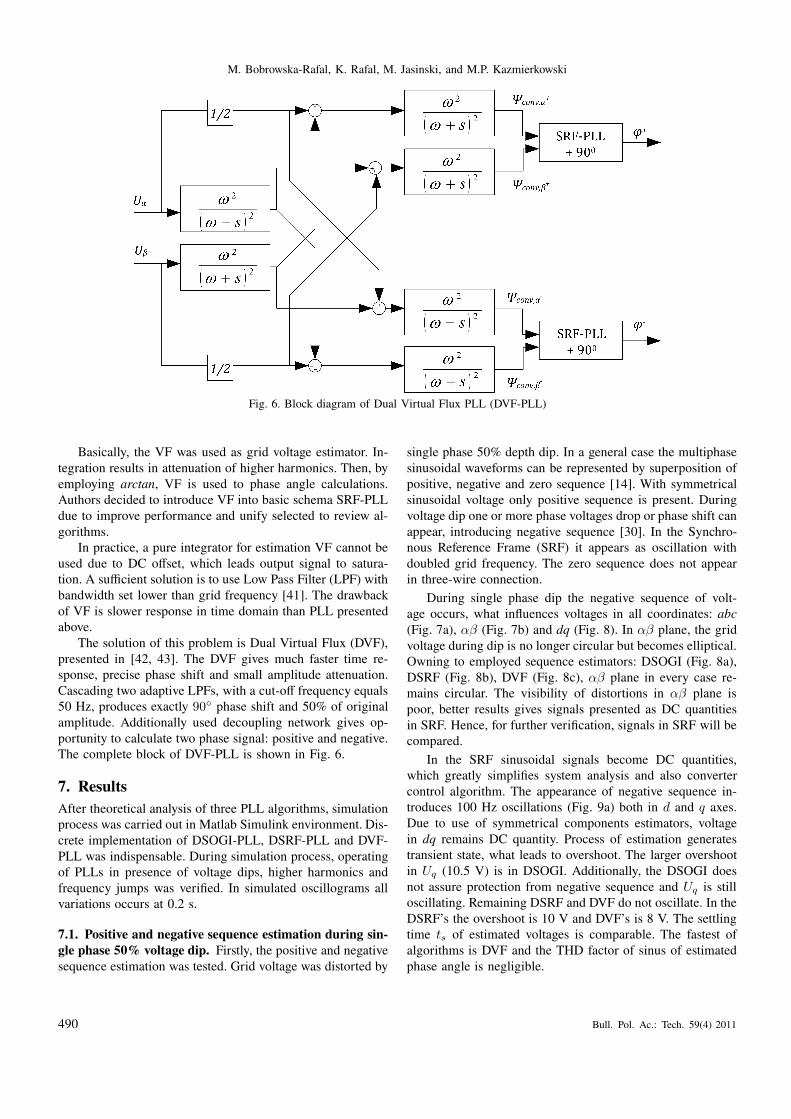
Fig. 6. Block diagram of Dual Virtual Flux PLL (DVF-PLL)
Basically, the VF was used as grid voltage estimator. In-
tegration results in attenuation of higher harmonics. Then, by
employing arctan, VF is used to phase angle calculations.
Authors decided to introduce VF into basic schema SRF-PLL
due to improve performance and unify selected to review al-
gorithms.
In practice, a pure integrator for estimation VF cannot be
used due to DC offset, which leads output signal to satura-
tion. A sufficient solution is to use Low Pass Filter (LPF) with
bandwidth set lower than grid frequency [41]. The drawback
of VF is slower response in time domain than PLL presented
above.
The solution of this problem is Dual Virtual Flux (DVF),
presented in [42, 43]. The DVF gives much faster time re-
sponse, precise phase shift and small amplitude attenuation.
Cascading two adaptive LPFs, with a cut-off frequency equals
50 Hz, produces exactly 90◦ phase shift and 50% of original
amplitude. Additionally used decoupling network gives op-
portunity to calculate two phase signal: positive and negative.
The complete block of DVF-PLL is shown in Fig. 6.
7. Results
After theoretical analysis of three PLL algorithms, simulation
process was carried out in Matlab Simulink environment. Dis-
crete implementation of DSOGI-PLL, DSRF-PLL and DVF-
PLL was indispensable. During simulation process, operating
of PLLs in presence of voltage dips, higher harmonics and
frequency jumps was verified. In simulated oscillograms all
variations occurs at 0.2 s.
7.1. Positive and negative sequence estimation during sin-
gle phase 50% voltage dip. Firstly, the positive and negative
sequence estimation was tested. Grid voltage was distorted by
single phase 50% depth dip. In a general case the multiphase
sinusoidal waveforms can be represented by superposition of
positive, negative and zero sequence [14]. With symmetrical
sinusoidal voltage only positive sequence is present. During
voltage dip one or more phase voltages drop or phase shift can
appear, introducing negative sequence [30]. In the Synchro-
nous Reference Frame (SRF) it appears as oscillation with
doubled grid frequency. The zero sequence does not appear
in three-wire connection.
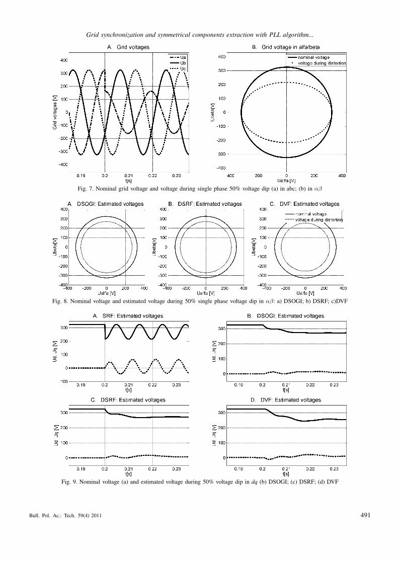
During single phase dip the negative sequence of volt-
age occurs, what influences voltages in all coordinates: abc
(Fig. 7a), αβ (Fig. 7b) and dq (Fig. 8). In αβ plane, the grid
voltage during dip is no longer circular but becomes elliptical.
Owning to employed sequence estimators: DSOGI (Fig. 8a),
DSRF (Fig. 8b), DVF (Fig. 8c), αβ plane in every case re-
mains circular. The visibility of distortions in αβ plane is
poor, better results gives signals presented as DC quantities
in SRF. Hence, for further verification, signals in SRF will be
compared.
In the SRF sinusoidal signals become DC quantities,
which greatly simplifies system analysis and also converter
control algorithm. The appearance of negative sequence in-
troduces 100 Hz oscillations (Fig. 9a) both in d and q axes.
Due to use of symmetrical components estimators, voltage
in dq remains DC quantity. Process of estimation generates
transient state, what leads to overshoot. The larger overshoot
in Uq (10.5 V) is in DSOGI. Additionally, the DSOGI does
not assure protection from negative sequence and Uq is still
oscillating. Remaining DSRF and DVF do not oscillate. In the
DSRF’s the overshoot is 10 V and DVF’s is 8 V. The settling
time ts of estimated voltages is comparable. The fastest of
algorithms is DVF and the THD factor of sinus of estimated
phase angle is negligible.
490 Bull. Pol. Ac.: Tech. 59(4) 2011
Grid synchronization and symmetrical components extraction with PLL algorithm...
Fig. 7. Nominal grid voltage and voltage during single phase 50% voltage dip (a) in abc; (b) in αβ
Fig. 8. Nominal voltage and estimated voltage during 50% single phase voltage dip in αβ: a) DSOGI; b) DSRF; c)DVF
Fig. 9. Nominal voltage (a) and estimated voltage during 50% voltage dip in dq (b) DSOGI; (c) DSRF; (d) DVF
Bull. Pol. Ac.: Tech. 59(4) 2011 491
M. Bobrowska-Rafal, K. Rafal, M. Jasinski, and M.P. Kazmierkowski
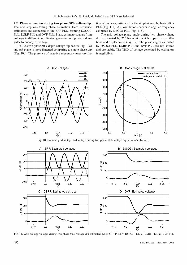
7.2. Phase estimation during two phase 50% voltage dip.
The next step was testing phase estimation. Here, sequence
estimators are connected to the SRF-PLL, forming DSOGI-
PLL, DSRF-PLL and DVF-PLL. Phase estimators, apart from
voltages in different coordinates, generate both phase and an-
gular frequency of voltage.
In 0.2 s two phase 50% depth voltage dip occurs (Fig. 10a)
and αβ plane is more flattened comparing to single phase dip
(Fig. 10b). The presence of negative sequence causes oscilla-
tion of voltages, estimated in the simplest way by basic SRF-
PLL (Fig. 11a). Als, oscillations occurs in angular frequency
estimated by DSOGI-PLL (Fig. 11b).
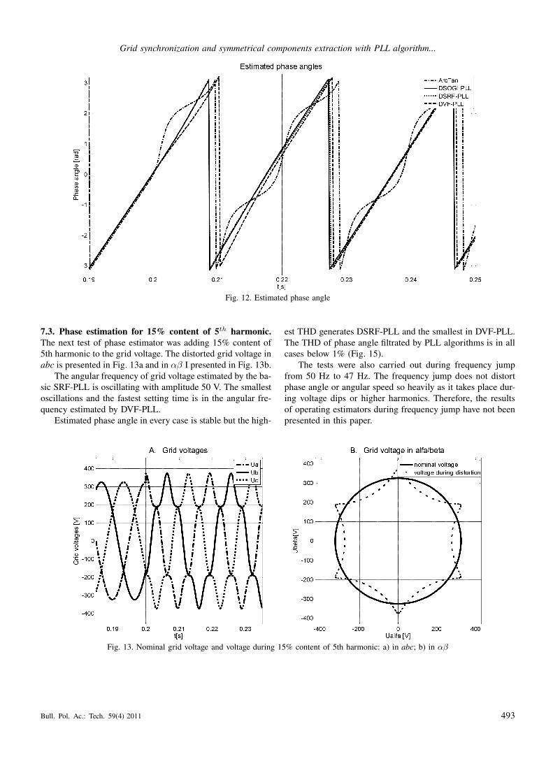
The grid voltage phase angle during two phase voltage
dip is distorted by 2nd harmonic, which appears as oscilla-
tions and displacement (Fig. 12). The phase angles estimated
by DSOGI-PLL, DSRF-PLL and DVF-PLL are not shifted
and are stable. The THD of voltage generated by estimators
is negligible.
Fig. 10. Nominal grid voltage and voltage during two phase 50% voltage dip: a) in abc; b) in αβ
Fig. 11. Grid voltage voltages during two phase 50% voltage dip estimated by: a) SRF-PLL; b) DSOGI-PLL; c) DSRF-PLL; d) DVF-PLL
492 Bull. Pol. Ac.: Tech. 59(4) 2011
Grid synchronization and symmetrical components extraction with PLL algorithm...
Fig. 12. Estimated phase angle
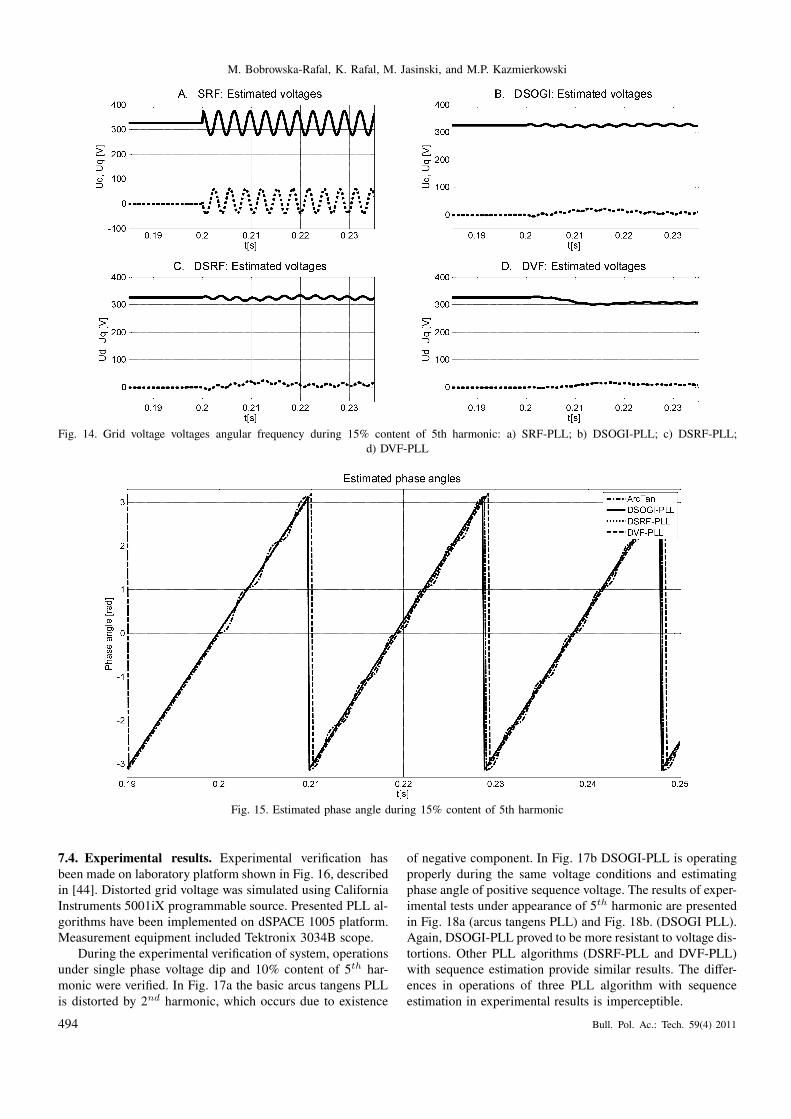
7.3. Phase estimation for 15% content of 5th harmonic.
The next test of phase estimator was adding 15% content of
5th harmonic to the grid voltage. The distorted grid voltage in
abc is presented in Fig. 13a and in αβ I presented in Fig. 13b.
The angular frequency of grid voltage estimated by the ba-
sic SRF-PLL is oscillating with amplitude 50 V. The smallest
oscillations and the fastest setting time is in the angular fre-
quency estimated by DVF-PLL.
Estimated phase angle in every case is stable but the high-
est THD generates DSRF-PLL and the smallest in DVF-PLL.
The THD of phase angle filtrated by PLL algorithms is in all
cases below 1% (Fig. 15).
The tests were also carried out during frequency jump
from 50 Hz to 47 Hz. The frequency jump does not distort
phase angle or angular speed so heavily as it takes place dur-
ing voltage dips or higher harmonics. Therefore, the results
of operating estimators during frequency jump have not been
presented in this paper.
Fig. 13. Nominal grid voltage and voltage during 15% content of 5th harmonic: a) in abc; b) in αβ
Bull. Pol. Ac.: Tech. 59(4) 2011 493
M. Bobrowska-Rafal, K. Rafal, M. Jasinski, and M.P. Kazmierkowski
Fig. 14. Grid voltage voltages angular frequency during 15% content of 5th harmonic: a) SRF-PLL; b) DSOGI-PLL; c) DSRF-PLL;
d) DVF-PLL
Fig. 15. Estimated phase angle during 15% content of 5th harmonic
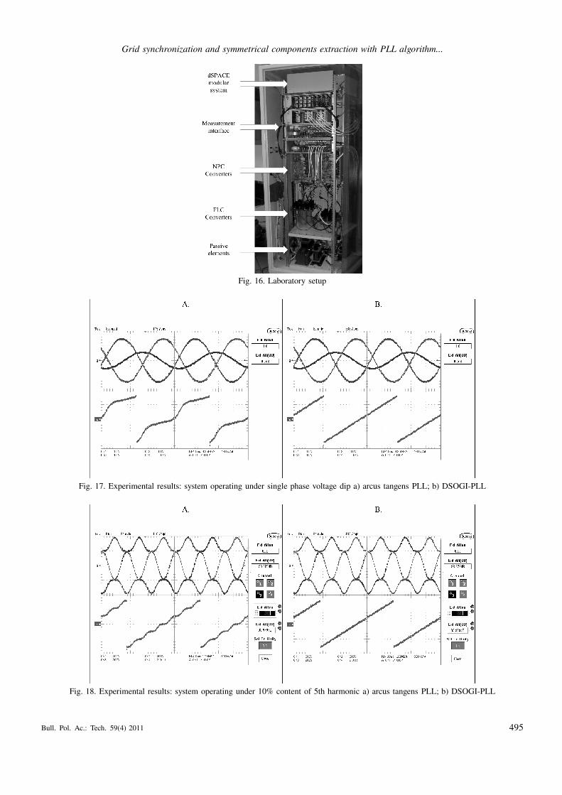
7.4. Experimental results. Experimental verification has
been made on laboratory platform shown in Fig. 16, described
in [44]. Distorted grid voltage was simulated using California
Instruments 5001iX programmable source. Presented PLL al-
gorithms have been implemented on dSPACE 1005 platform.
Measurement equipment included Tektronix 3034B scope.
During the experimental verification of system, operations
under single phase voltage dip and 10% content of 5th har-
monic were verified. In Fig. 17a the basic arcus tangens PLL
is distorted by 2nd harmonic, which occurs due to existence
of negative component. In Fig. 17b DSOGI-PLL is operating
properly during the same voltage conditions and estimating
phase angle of positive sequence voltage. The results of exper-
imental tests under appearance of 5th harmonic are presented
in Fig. 18a (arcus tangens PLL) and Fig. 18b. (DSOGI PLL).
Again, DSOGI-PLL proved to be more resistant to voltage dis-
tortions. Other PLL algorithms (DSRF-PLL and DVF-PLL)
with sequence estimation provide similar results. The differ-
ences in operations of three PLL algorithm with sequence
estimation in experimental results is imperceptible.
494 Bull. Pol. Ac.: Tech. 59(4) 2011
Grid synchronization and symmetrical components extraction with PLL algorithm...
Fig. 16. Laboratory setup
Fig. 17. Experimental results: system operating under single phase voltage dip a) arcus tangens PLL; b) DSOGI-PLL
Fig. 18. Experimental results: system operating under 10% content of 5th harmonic a) arcus tangens PLL; b) DSOGI-PLL
Bull. Pol. Ac.: Tech. 59(4) 2011 495
M. Bobrowska-Rafal, K. Rafal, M. Jasinski, and M.P. Kazmierkowski
8. Conclusions
This paper presents the review and comprison of PLL algo-
rithms. Three groups of PLL algorithms are distinguished,
due to signals transformations: basic in abc, αβ and in dq co-
ordinates. To evaluate best PLL algorithm, a set of criterions,
based on DC quantities in dq axes, were proposed (overshoot
and settling time of voltage Uq and angular speed error ∆ω,
THD content in phase angle).
During tests, operation of three selected algorithms
(DSOGI-PLL, DSRF-PLL and DVF-PLL) under grid voltage
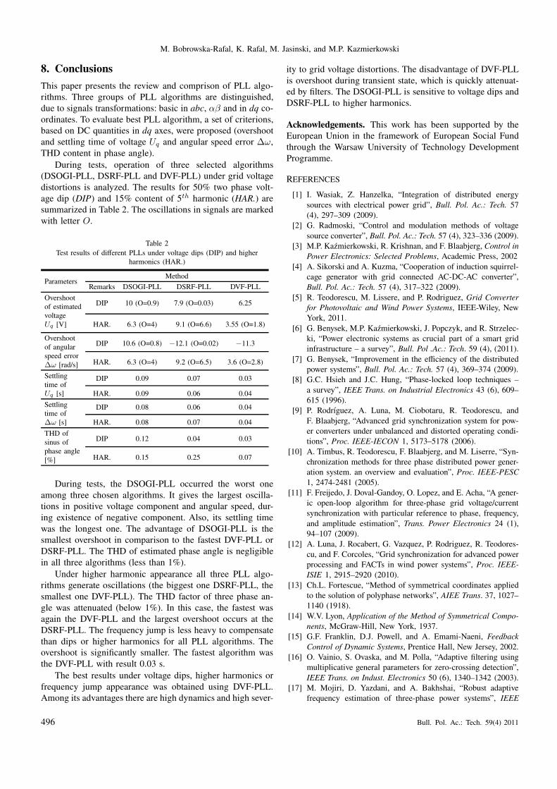
distortions is analyzed. The results for 50% two phase volt-
age dip (DIP) and 15% content of 5th harmonic (HAR.) are
summarized in Table 2. The oscillations in signals are marked
with letter O.
Table 2
Test results of different PLLs under voltage dips (DIP) and higher
harmonics (HAR.)
ParametersMethod
Remarks DSOGI-PLL DSRF-PLL DVF-PLL
Overshoot
of estimated
voltage
Uq [V]
DIP 10 (O=0.9) 7.9 (O=0.03) 6.25
HAR. 6.3 (O=4) 9.1 (O=6.6) 3.55 (O=1.8)
Overshoot
of angular
speed error
∆ω [rad/s]
DIP 10.6 (O=0.8) −12.1 (O=0.02) −11.3
HAR. 6.3 (O=4) 9.2 (O=6.5) 3.6 (O=2.8)
Settling
time of
Uq [s]
DIP 0.09 0.07 0.03
HAR. 0.09 0.06 0.04
Settling
time of
∆ω [s]
DIP 0.08 0.06 0.04
HAR. 0.08 0.07 0.04
THD of
sinus of
phase angle
[%]
DIP 0.12 0.04 0.03
HAR. 0.15 0.25 0.07
During tests, the DSOGI-PLL occurred the worst one
among three chosen algorithms. It gives the largest oscilla-
tions in positive voltage component and angular speed, dur-
ing existence of negative component. Also, its settling time
was the longest one. The advantage of DSOGI-PLL is the
smallest overshoot in comparison to the fastest DVF-PLL or
DSRF-PLL. The THD of estimated phase angle is negligible
in all three algorithms (less than 1%).
Under higher harmonic appearance all three PLL algo-
rithms generate oscillations (the biggest one DSRF-PLL, the
smallest one DVF-PLL). The THD factor of three phase an-
gle was attenuated (below 1%). In this case, the fastest was
again the DVF-PLL and the largest overshoot occurs at the
DSRF-PLL. The frequency jump is less heavy to compensate
than dips or higher harmonics for all PLL algorithms. The
overshoot is significantly smaller. The fastest algorithm was
the DVF-PLL with result 0.03 s.
The best results under voltage dips, higher harmonics or
frequency jump appearance was obtained using DVF-PLL.
Among its advantages there are high dynamics and high sever-
ity to grid voltage distortions. The disadvantage of DVF-PLL
is overshoot during transient state, which is quickly attenuat-
ed by filters. The DSOGI-PLL is sensitive to voltage dips and
DSRF-PLL to higher harmonics.
Acknowledgements. This work has been supported by the
European Union in the framework of European Social Fund
through the Warsaw University of Technology Development
Programme.
REFERENCES
[1] I. Wasiak, Z. Hanzelka, “Integration of distributed energy
sources with electrical power grid”, Bull. Pol. Ac.: Tech. 57
(4), 297–309 (2009).
[2] G. Radmoski, “Control and modulation methods of voltage
source converter”, Bull. Pol. Ac.: Tech. 57 (4), 323–336 (2009).
[3] M.P. Kaźmierkowski, R. Krishnan, and F. Blaabjerg, Control in
Power Electronics: Selected Problems, Academic Press, 2002
[4] A. Sikorski and A. Kuzma, “Cooperation of induction squirrel-
cage generator with grid connected AC-DC-AC converter”,
Bull. Pol. Ac.: Tech. 57 (4), 317–322 (2009).
[5] R. Teodorescu, M. Lissere, and P. Rodriguez, Grid Converter
for Photovoltaic and Wind Power Systems, IEEE-Wiley, New
York, 2011.
[6] G. Benysek, M.P. Kaźmierkowski, J. Popczyk, and R. Strzelec-
ki, “Power electronic systems as crucial part of a smart grid
infrastructure – a survey”, Bull. Pol .Ac.: Tech. 59 (4), (2011).
[7] G. Benysek, “Improvement in the efficiency of the distributed
power systems”, Bull. Pol. Ac.: Tech. 57 (4), 369–374 (2009).
[8] G.C. Hsieh and J.C. Hung, “Phase-locked loop techniques –
a survey”, IEEE Trans. on Industrial Electronics 43 (6), 609–
615 (1996).
[9] P. Rodrıguez, A. Luna, M. Ciobotaru, R. Teodorescu, and
F. Blaabjerg, “Advanced grid synchronization system for pow-
er converters under unbalanced and distorted operating condi-
tions”, Proc. IEEE-IECON 1, 5173–5178 (2006).
[10] A. Timbus, R. Teodorescu, F. Blaabjerg, and M. Liserre, “Syn-
chronization methods for three phase distributed power gener-
ation system. an overview and evaluation”, Proc. IEEE-PESC
1, 2474-2481 (2005).
[11] F. Freijedo, J. Doval-Gandoy, O. Lopez, and E. Acha, “A gener-
ic open-loop algorithm for three-phase grid voltage/current
synchronization with particular reference to phase, frequency,
and amplitude estimation”, Trans. Power Electronics 24 (1),
94–107 (2009).
[12] A. Luna, J. Rocabert, G. Vazquez, P. Rodriguez, R. Teodores-
cu, and F. Corcoles, “Grid synchronization for advanced power
processing and FACTs in wind power systems”, Proc. IEEE-
ISIE 1, 2915–2920 (2010).
[13] Ch.L. Fortescue, “Method of symmetrical coordinates applied
to the solution of polyphase networks”, AIEE Trans. 37, 1027–
1140 (1918).
[14] W.V. Lyon, Application of the Method of Symmetrical Compo-
nents, McGraw-Hill, New York, 1937.
[15] G.F. Franklin, D.J. Powell, and A. Emami-Naeni, Feedback
Control of Dynamic Systems, Prentice Hall, New Jersey, 2002.
[16] O. Vainio, S. Ovaska, and M. Polla, “Adaptive filtering using
multiplicative general parameters for zero-crossing detection”,
IEEE Trans. on Indust. Electronics 50 (6), 1340–1342 (2003).
[17] M. Mojiri, D. Yazdani, and A. Bakhshai, “Robust adaptive
frequency estimation of three-phase power systems”, IEEE
496 Bull. Pol. Ac.: Tech. 59(4) 2011
Grid synchronization and symmetrical components extraction with PLL algorithm...
Trans. on Instrumentation and Measurement 59 (7), 1793–
1802 (2010).
[18] A. Nicastri and A. Nagliero, “Comparision and evaluation of
PLL techniques for the design of the grid-connected inverter
systems”, Proc. IEEE-ISIE 1, 3865–3870 (2010).
[19] A. Timbus, M. Liserre, R. Teodorescu, P. Rodriguez, and
F. Blaabjerg, “PLL algorithm for power generation sys tems
robust to grid voltage faults”, Proc. IEEE-PESC 1, 1–7 (2007).
[20] M. Saitou, N. Matsui, and T. Shimizu, “A control strategy of
single-phase active filter using a novel d-q transformation”,
Proc. IEEE-IAS 1, 1222–1227 (2003).
[21] S. Luo and Z. Hou, “An adaptive detecting method for harmon-
ic and reactive currents”, IEEE Trans. on Indust. Electronics
42 (1), 334–338 (1995).
[22] H. Yoo, J. Kim, and S. Sul, “Sensorless operation of PWM rec-
tifier for distributed generation”, IEEE Trans. on Power Elec-
tronics 22 (3), 1014–1018 (2007).
[23] A. Nicastri and A Nagliero, “ Comparision and evaluation of
the PLL techniques for design of grid-connected inverter sys-
tems”, Proc. IEEE-ICECS 1, 3865–3870 (2008).
[24] E. Robles, S. Ceballos, J. Pou, J. Zaragoza, and I. Gabiola,
“Grid synchronization method based on quasi-ideal low pass
filter stage and phase locked loop”, Proc. IEEE-PESC 1, 4056–
4061 (2008).
[25] Y. Wang and Y. Li, “Analysis and digital implementation of
cascaded delayed-signal-cancellation PLL”, Trans. on Power
Electronics 26 (4), 1067–1080 (2011).
[26] X. Yuan, W. Merk, H. Stemmler, and J. Allmeling, “Stationary-
frame generalized integrators for current control of active pow-
er filters with zero steady-state error for current harmonics of
concern under unbalanced and distorted operating conditions”,
IEEE Trans. on Indust. Applications 38 (2), 2143–2150 (2002).
[27] O. Krievs, I. Steiks, and L. Ribickis, “A PLL scheme for syn-
chronization with grid voltage phasor in active power filter
systems”, Sci. J. Riga Technical University: Power and Elec-
trical Eng. 27, 133–136 (2010).
[28] F. Freijedo, A. Yepes, O. Lopez, A. Vidal, and J. Doval-
Gandoy, “Three-phase PLLs with fast postfault retracking and
steady-state rejection of voltage unbalance and harmonics by
means of lead compensation”, Trans. on Power Electronics 26
(1), 85–97 (2011).
[29] P. Rodrıguez, J. Pou, J. Bergas, I. Candela, R. Burgos, and
D. Boroyevich, “Double synchronous reference frame PLL
for power converters control”, Proc. IEEE-PESC 1, 584–592
(2005).
[30] M. Bobrowska-Rafal, K. Rafal, G. Abad, and M. Jasinski,
“Control of PWM rectifier under grid voltage dips”, Bull. Pol.
Ac.: Tech. 57 (4), 337–343 (2009).
[31] P. Rodriguez, A. Luna, R. Teodorescu, and F. Blabjerg, “Grid
synchronization of wind turbine converters under transient grid
faults using a double synchronous reference frame PLL”, Proc.
Energy Conf. 1, 1–8 (2008).
[32] T. Le, “Kompensation schnell veranderlicher Blindstrome eines
Drehstromverbrauchers”, EtzArchiv, Bd. 11 H, 8 (1989).
[33] P. Xiao, K.A., Corzine, and G. Kumar, “Multiple reference
frame-based control of three-phase pwm boost rectifier under
unbalanced and distorted input conditions”, IEEE Trans. on
Power Electronics 23 (4), 2006–2017 (2008).
[34] X. Fang, Y. Wang, M. Li, K. Wang, and W. Lei, “A novel
PLL for grid synchronization of power electronic converters in
unbalanced and variable-frequency environment”, Proc. IEEE-
PEDG 1, 466–471 (2010).
[35] J. Svensson, “Synchronization methods for grid-connected
voltage source converters”, IEEE Proc. Generation, Transmis-
sion and Distribution 148 (3), 229–235 (2001).
[36] H. Kim, S. Lee, and S. Sul, “Reference wave generator in dy-
namic voltage restorer by use of PQR power theory”, Proc.
IEEE-APEC 1, 1452–1457 (2004).
[37] P. Rodriguez, R. Teodoresu, I. Candela, A. Timbus, M. Lis-
erre, and F. Blaabjerg, “New positive-sequence voltage detector
for grid synchronization of power converters under faulty grid
conditions”, Proc. IEEE-PESC 1, 1–7 (2006).
[38] S. Bhattacharya, A. Veltman, D.M. Divan, R.D. Lorenz, “Flux-
based active filter controller”, IEEE Trans. Indust. Applications
32 (3), 491–502 (1996).
[39] M. Chandorkar, “New control techniques for inverter flux”,
Proc. IEEE-IAS 1, 86–93 (1999).
[40] M. Malinowski, W. Szczygiel, M.P. Kaźmierkowski, and
S. Bernet, “Sensorless operation of active damping methods
for three-phase PWM converters”, Proc. IEEE-ISIE 1, 775–
780 (2005).
[41] W. Gullvik, L. Norum, and R. Nilsen, “Active damping of res-
onance oscillations in LCL-filters based on virtual flux and
virtual resistor”, Proc. IEEE-EPE 1, 1–10 (2007).
[42] M. Malinowski, “Sensorless control strategies for three-phase
PWM rectifiers”, Ph.D. Thesis, Warsaw University of Technol-
ogy, Warsaw, 2001.
[43] A. Kulka, “Sensorless digital control of grid connected three
phase converters for renewable sources”, Ph.D. Thesis, Nor-
wegian University of Science and Technology, Trondhein,
2009.
[44] K. Rafal, M. Bobrowska-Rafal, S. Piasecki, and M. Jasinski,
“Coordinated control of grid-connected three-level NPC con-
verter under distorted grid voltage”, Proc. IEEE-ISIE 1, 1011–
1016 (2011).
Bull. Pol. Ac.: Tech. 59(4) 2011 497