1
P. Stanev 1 F. P. Wardle 2 J. Corbett 1 1) Cranfield University, School of Industrial and Manufacturing Science, Bedford, UK 2) Loadpoint Ltd, Cricklade, Swindon, UK Grooved Hybrid Air Bearings Experiments Experimental work was aimed at validating the computer model. A machining spindle with integral high frequency motor and two partially grooved hybrid bearings was manufactured, fig 8. Pressure sensors were built into one of the bearings to measure the pumping effect of the grooves and a slave bearing and capacitance gauge were mounted on the front of the spindle to enable stiffness to be measured. Stiffness measurements were limited in speed to less than 40 000 rpm due to the characteristics of the slave bearing. However the latter could be removed and pressure measurements taken to the spindle’s maximum speed of 120 000 rpm. This speed limit being a function of the drive motor. Experimental measurements of spindle stiffness showed it to increase with speed. Factoring spindle stiffness to account for the overhang of the slave bearing and capacitance gauge enabled the bearing stiffness to be determined. Comparing bearing stiffness measured in this way with theoretical predictions from the computer model showed reasonable agreement over the range of speeds for which measurements could be taken. Pressure in the bearing journal measured midway between orifices in one row also increased with speed. For these measurements the spindle was not subjected to any load so the increase in pressure was predominantly due to the pumping effect of the grooves. Comparing experimental measurements of pressure with theoretical predictions from the computer model again showed reasonable agreement. Conclusions A computer model of a grooved hybrid bearing has been developed and demonstrated to give reasonable agreement with experimental measurements performed on a high speed spindle. Grooves can be added to otherwise conventional aerostatic bearing designs to modify their high speed performance. More specifically groove designs may be optimised to enhance bearing stiffness or stability at high speeds. Improvements in high speed stiffness or stability are however offset by a reduction in stiffness or stability at low speeds. Partially grooved bearing designs give maximum high speed stiffness with some improvement in high speed stability. Fully grooved bearing designs give maximum high speed stability but at the expense of bearing stiffness. Grooved hybrid air bearings combine aerostatic and aerodynamic design principles to optimise ultra high speed performance. Aerostatic lift is generated by feeding the bearing with pressurised air through orifice restrictors as in conventional bearing designs. Aerodynamic lift is controlled by the addition of helical grooves machined into the shaft or bearing journal. Partially grooved bearings (shown above) can be designed to improve high speed stiffness whereas fully grooved bearings may be designed to improve high speed stability. Ultra high Speed Machining Applications Bore Grinding Milling Micromachining Printed circuit board drilling In these applications machining spindles are run at speeds well in excess of 100,000 rpm. The spindles use aerostatic bearings because of :- Improved life at ultra high speeds Low friction losses Low motion errors Bearing diameters are usually more than 25 mm and surface speeds often exceed 3.0 x 10 6 DN (bearing bore in mm x shaft speed in rpm). Ultra High Speed Aerostatic Bearing Characteristics All aerostatic journal bearings develop an aerodynamic component of lift and at surface speeds as low as 0.5 x 10 6 DN this can exceed the aerostatic lift, fig 1 and hence dominate the bearing’s high speed performance. Aerodynamic lift increases bearing load capacity and stiffness but the benefits are at the expense of reduced stability. With aerodynamic lift being dominant at high speeds and with air spindles needing to use large diameter (heavy) shafts to maximise bearing stiffness the aerostatic bearing becomes prone to whirl. As for aerodynamic bearings the whirl frequency is close to one half of the shaft’s rotational speed and is usually excited when the rotational speed approaches twice the frequency of a critical speed of the spindle. This type of whirl is often referred to as ‘half speed whirl’ and is destructive in the sense that any attempt to run through it will lead to wear and ultimately seizure of the bearing. Half speed whirl therefore limits spindle speed to about twice the first critical speed of the spindle. Two whirl modes are common on ultra high speed aerostatic spindles, fig 2 and are known as ‘translational whirl’ or ‘conical whirl’. Whichever mode is predominant simply depends on the dynamic characteristics of the bearing - shaft system. Conical whirl is likely to occur in arrangements where the shaft overhang from the bearings is large and conversely translational whirl is more likely when overhangs are low. Grooved Hybrid Bearing The grooved hybrid bearing combines aerostatic and aerodynamic design principles. It contains helical grooves, either on the shaft or in the journal bore, located outboard of the air feed jets and arranged to pump air into the centre of the bearing when the shaft rotates, fig 3. At high speeds the grooves pumping action significantly changes the pressure distribution within the bearing and can improve load carrying capacity and stiffness. The grooves also change the air velocity gradients in the bearing affecting the basic mechanism of whirl instability inherent in fluid film journal bearings - usually improving the threshold at which instability occurs. Grooves may extend the full length of the bearing or part way across the bearing depending upon required operating characteristics. In general, fully grooved bearings give better stability whereas partially grooved bearings may give better stiffness and load carrying capacity. The improvements being confined to high rotational speeds. Parametric Studies Grooved hybrid bearings have a large number of design parameters and optimum designs are most easily identified with the aid of a computer model that simulates air flow through the bearing. Such a model has been developed and used to study the effect of groove parameters on bearing stiffness and stability. Figs 4 to 7 give some examples of the results. In these figures bearing speed is represented by the non dimensional parameter Compressibility Number defined as :- Λ= 6µω (R/C) 2 /P a where µ is the viscosity of air, ω is bearing rotational speed, R is shaft radius, C is clearance measured over ridges and P a is atmospheric pressure. Fig 4 illustrates that in the case of a partially grooved hybrid bearing there is an optimum groove depth which gives maximum stiffness at high speeds. The improvement over a conventional aerostatic bearing though is at the expense of low speed stiffness. The partially grooved hybrid bearing giving the maximum stiffness in fig 4 also exhibits high stability, fig 5. The improvement over a conventional aerostatic bearing is only significant at high speeds, however this is an important advantage as for aerostatic bearings stability is seldom an issue at low speeds. For the case of a fully grooved hybrid bearing the improvement in high speed stability over a plain hydrostatic bearing can be substantial, fig 6. However the additional stability is at the expense of stiffness which is lower than that of the conventional bearing throughout the speed range, fig 7.

Grooved Hybrid Air Bearings - loadpoint-bearings.co.uk€¦ · Grooved Hybrid Air Bearings ... Grooved hybrid bearings have a large number of design parameters and ... speed stability

  • Upload
    vanminh

  • View
    228

  • Download
    4

Embed Size (px)

Citation preview

P. Stanev1 F. P. Wardle2 J. Corbett11) Cranfield University, School of Industrial and Manufacturing Science, Bedford, UK2) Loadpoint Ltd, Cricklade, Swindon, UK

Grooved Hybrid Air Bearings

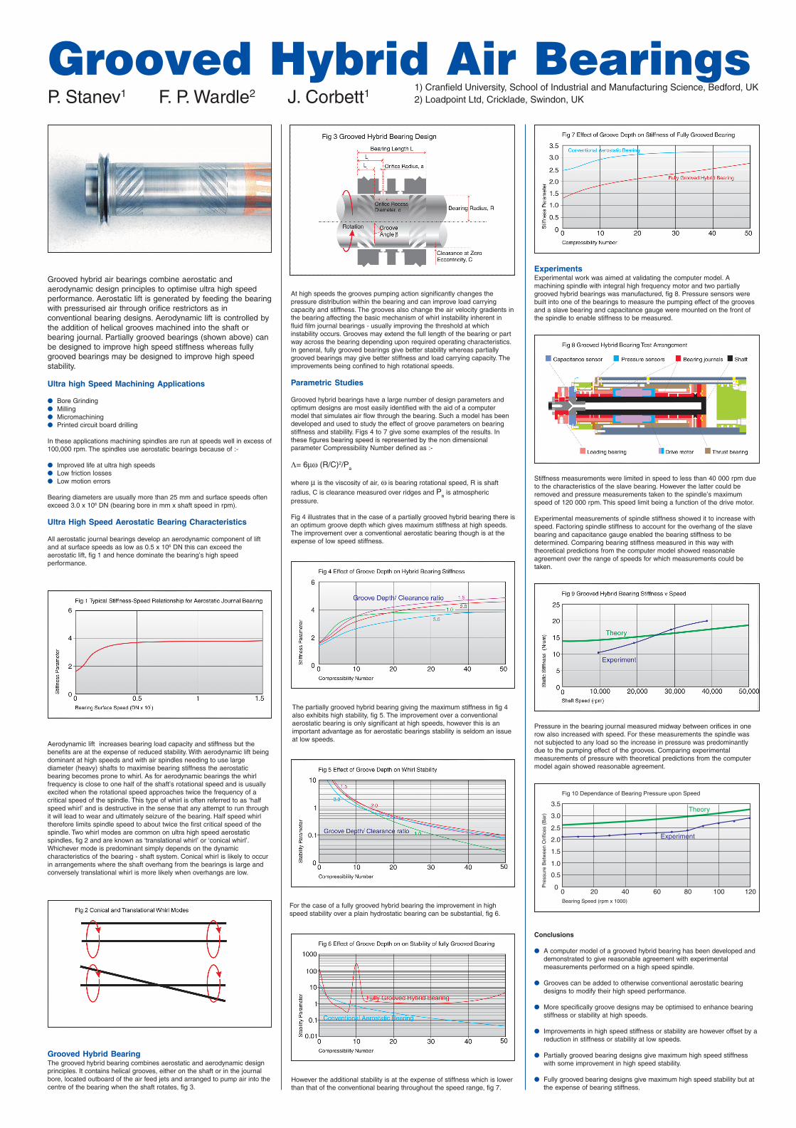
ExperimentsExperimental work was aimed at validating the computer model. Amachining spindle with integral high frequency motor and two partiallygrooved hybrid bearings was manufactured, fig 8. Pressure sensors werebuilt into one of the bearings to measure the pumping effect of the groovesand a slave bearing and capacitance gauge were mounted on the front ofthe spindle to enable stiffness to be measured.

Stiffness measurements were limited in speed to less than 40 000 rpm dueto the characteristics of the slave bearing. However the latter could beremoved and pressure measurements taken to the spindle’s maximumspeed of 120 000 rpm. This speed limit being a function of the drive motor.

Experimental measurements of spindle stiffness showed it to increase withspeed. Factoring spindle stiffness to account for the overhang of the slavebearing and capacitance gauge enabled the bearing stiffness to bedetermined. Comparing bearing stiffness measured in this way withtheoretical predictions from the computer model showed reasonableagreement over the range of speeds for which measurements could betaken.

Pressure in the bearing journal measured midway between orifices in onerow also increased with speed. For these measurements the spindle wasnot subjected to any load so the increase in pressure was predominantlydue to the pumping effect of the grooves. Comparing experimentalmeasurements of pressure with theoretical predictions from the computermodel again showed reasonable agreement.

Conclusions

● A computer model of a grooved hybrid bearing has been developed anddemonstrated to give reasonable agreement with experimentalmeasurements performed on a high speed spindle.

● Grooves can be added to otherwise conventional aerostatic bearingdesigns to modify their high speed performance.

● More specifically groove designs may be optimised to enhance bearingstiffness or stability at high speeds.

● Improvements in high speed stiffness or stability are however offset by areduction in stiffness or stability at low speeds.

● Partially grooved bearing designs give maximum high speed stiffnesswith some improvement in high speed stability.

● Fully grooved bearing designs give maximum high speed stability but atthe expense of bearing stiffness.

Grooved hybrid air bearings combine aerostatic andaerodynamic design principles to optimise ultra high speedperformance. Aerostatic lift is generated by feeding the bearingwith pressurised air through orifice restrictors as inconventional bearing designs. Aerodynamic lift is controlled bythe addition of helical grooves machined into the shaft orbearing journal. Partially grooved bearings (shown above) canbe designed to improve high speed stiffness whereas fullygrooved bearings may be designed to improve high speedstability.

Ultra high Speed Machining Applications

● Bore Grinding● Milling● Micromachining● Printed circuit board drilling

In these applications machining spindles are run at speeds well in excess of100,000 rpm. The spindles use aerostatic bearings because of :-

● Improved life at ultra high speeds● Low friction losses● Low motion errors

Bearing diameters are usually more than 25 mm and surface speeds oftenexceed 3.0 x 10⁶ DN (bearing bore in mm x shaft speed in rpm).

Ultra High Speed Aerostatic Bearing Characteristics

All aerostatic journal bearings develop an aerodynamic component of liftand at surface speeds as low as 0.5 x 10⁶ DN this can exceed theaerostatic lift, fig 1 and hence dominate the bearing’s high speedperformance.

Aerodynamic lift increases bearing load capacity and stiffness but thebenefits are at the expense of reduced stability. With aerodynamic lift beingdominant at high speeds and with air spindles needing to use largediameter (heavy) shafts to maximise bearing stiffness the aerostaticbearing becomes prone to whirl. As for aerodynamic bearings the whirlfrequency is close to one half of the shaft’s rotational speed and is usuallyexcited when the rotational speed approaches twice the frequency of acritical speed of the spindle. This type of whirl is often referred to as ‘halfspeed whirl’ and is destructive in the sense that any attempt to run throughit will lead to wear and ultimately seizure of the bearing. Half speed whirltherefore limits spindle speed to about twice the first critical speed of thespindle. Two whirl modes are common on ultra high speed aerostaticspindles, fig 2 and are known as ‘translational whirl’ or ‘conical whirl’.Whichever mode is predominant simply depends on the dynamiccharacteristics of the bearing - shaft system. Conical whirl is likely to occurin arrangements where the shaft overhang from the bearings is large andconversely translational whirl is more likely when overhangs are low.

Grooved Hybrid BearingThe grooved hybrid bearing combines aerostatic and aerodynamic designprinciples. It contains helical grooves, either on the shaft or in the journalbore, located outboard of the air feed jets and arranged to pump air into thecentre of the bearing when the shaft rotates, fig 3.

At high speeds the grooves pumping action significantly changes thepressure distribution within the bearing and can improve load carryingcapacity and stiffness. The grooves also change the air velocity gradients inthe bearing affecting the basic mechanism of whirl instability inherent influid film journal bearings - usually improving the threshold at whichinstability occurs. Grooves may extend the full length of the bearing or partway across the bearing depending upon required operating characteristics.In general, fully grooved bearings give better stability whereas partiallygrooved bearings may give better stiffness and load carrying capacity. Theimprovements being confined to high rotational speeds.

Parametric Studies

Grooved hybrid bearings have a large number of design parameters andoptimum designs are most easily identified with the aid of a computermodel that simulates air flow through the bearing. Such a model has beendeveloped and used to study the effect of groove parameters on bearingstiffness and stability. Figs 4 to 7 give some examples of the results. Inthese figures bearing speed is represented by the non dimensionalparameter Compressibility Number defined as :-

Λ= 6µω (R/C)2/Pa

where µ is the viscosity of air, ω is bearing rotational speed, R is shaftradius, C is clearance measured over ridges and Pa is atmosphericpressure.

Fig 4 illustrates that in the case of a partially grooved hybrid bearing there isan optimum groove depth which gives maximum stiffness at high speeds.The improvement over a conventional aerostatic bearing though is at theexpense of low speed stiffness.

The partially grooved hybrid bearing giving the maximum stiffness in fig 4also exhibits high stability, fig 5. The improvement over a conventionalaerostatic bearing is only significant at high speeds, however this is animportant advantage as for aerostatic bearings stability is seldom an issueat low speeds.

For the case of a fully grooved hybrid bearing the improvement in highspeed stability over a plain hydrostatic bearing can be substantial, fig 6.

However the additional stability is at the expense of stiffness which is lowerthan that of the conventional bearing throughout the speed range, fig 7.