Embed Size (px)
Citation preview
IOP PUBLISHING CLASSICAL AND QUANTUM GRAVITY
Class. Quantum Grav. 25 (2008) 114013 (15pp) doi:10.1088/0264-9381/25/11/114013
Ground-based gravitational-wave detection: now andfuture
Stanley E Whitcomb
LIGO Laboratory, California Institute of Technology, Pasadena, CA 91125, USA
E-mail: whitcomb [email protected]
Received 2 December 2007, in final form 2 March 2008Published 15 May 2008Online at stacks.iop.org/CQG/25/114013
AbstractIn the past three years, the first generation of large gravitational-waveinterferometers has begun operation near their design sensitivities, takingup the mantle from the bar detectors that pioneered the search for the firstdirect detection of gravitational waves. Even as the current ground-basedinterferometers were reaching their design sensitivities, plans were being laidfor the future. Advances in technology and lessons learned from the firstgeneration devices have pointed the way to an order of magnitude improvementin sensitivity, as well as expanded frequency ranges and the capability to tailorthe sensitivity band to address particular astrophysical sources. Advancedcryogenic acoustic detectors, the successors to the current bar detectors, arebeing researched and may play a role in the future, particularly at the higherfrequencies. One of the most important trends is the growing internationalcooperation aimed at building a truly global network. In this paper, I surveythe state of the various detectors as of mid-2007, and outline the prospects forthe future.
PACS numbers: 04.80.Nn, 95.55.Ym
(Some figures in this article are in colour only in the electronic version)
1. Introduction: looking forward and looking back
Conferences such as this one provide us with markers in time, helping us measure the changesthat have taken place in our field and the progress we have made. This gathering, in particular,finds us at an important transition for gravitational-wave detection. Since the last Amaldiand GR meetings, we have seen a shift in the leadership in gravitational-wave observations.The current generation of acoustic detectors (‘bar detectors’), along the main observationalinstruments, have been surpassed in sensitivity by laser interferometer based detectors capableof extended observations. After more than two decades of development and construction,
0264-9381/08/114013+15$30.00 © 2008 IOP Publishing Ltd Printed in the UK 1
Class. Quantum Grav. 25 (2008) 114013 S E Whitcomb
these interferometric detectors are now at the leading edge of ground-based gravitational-wave detection.
A second trend that I would like to emphasize is the growth in importance ofdetector networks. Although the oldest global network of gravitational-wave detectors, theInternational Gravitational Event Collaboration (IGEC), was established ten years ago, the pastfive years have seen an explosive growth in the level of collaboration and joint observationsin the gravitational-wave community. Today, virtually every search for gravitational wavesunderway involves multiple projects collaborating across national and continental boundaries.
In this paper, I will summarize the capabilities of currently operating detectors and howthese detectors are coming together to form a truly global network. I will describe theimprovements which are underway or are planned for these detectors, and briefly outline theaspirations and dreams for the more distant future. I will not discuss the observational resultsto date, as these are covered in another plenary talk.
2. Bar detectors: the culmination of the first era in gravitational-wave detection
Bar detectors, resonant cylinders whose vibrational modes can be excited by the passageof a gravitational wave, hold a special place in the field of ground-based gravitational-wavedetectors. J Weber built the first bar detector in the 1960s, creating from nothing the new field ofgravitational-wave detection. Weber’s initial announcement that he had observed gravitationalwaves [1] triggered an intense interest in gravitational waves, even though his findings were notconfirmed by later experiments. As the field evolved over the next 40 years, at least 19 differentbar detectors in 8 countries were built and used in searches for gravitational waves. A total ofseveral hundred scientists, students, engineers and technicians were involved in this effort, andmany of the current leaders in the field, including a number who now work on interferometricdetectors, got their start working on bar detectors. The pioneering work of this communityproduced new understanding of important noise sources that can affect a variety of precisionmeasurements: thermal/Brownian noise, back action/quantum noise, seismic/acoustic noise.It also produced a number of technological achievements in large cryogenic systems, low-noise displacement transducers and electronics. The exciting prospect that these detectorsmight see the first evidence of gravitational waves also triggered a corresponding interest intheoretical studies of possible sources, leading to much improved predictions of their strength.We now know that even the strongest gravitational waves incident on the surface of the earth(in the frequency bands where one can build sensitive ground-based detectors) typically havean intrinsic strain of 10−20 or less, corresponding to changes in lengths much smaller than thediameter of a proton even over kilometer-scale distances.
By 1997, in the absence of a confirmed detection, this large community has shrunkto just four groups operating five cryogenic bar detectors, but these groups initiated anew level of collaboration. Representatives of all five detectors came together in 1997 inPerth to create the first worldwide gravitational-wave network, the International GravitationalEvent Collaboration (IGEC) [2]. IGEC included all operating bar detectors in the world:EXPLORER (CERN) NAUTILUS (INFN Frascati Laboratory), AURIGA (INFN LegnaroLaboratory), ALLEGRO (Louisiana State University) and NIOBE (University of WesternAustralia). The initial period of operation of IGEC [3] covered four years of coordinatedobservations from 1997 through 2000, resulting in 26 days of observation with four detectorstaking data, 173 days of three-fold coverage and 707 days of two-fold coverage.
These initial data run by IGEC were followed by a series of upgrades to the differentdetectors. Major upgrades to the cryogenics, the suspensions, the tranducers and dc-SQUIDamplifiers for EXPLORER and NAUTILUS were completed in 2000 and 2003, respectively,
2
Class. Quantum Grav. 25 (2008) 114013 S E Whitcomb
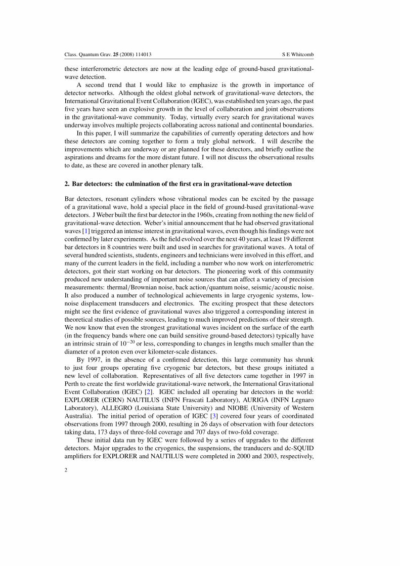
Figure 1. Strain sensitivity (noise level) versus frequency for the four current IGEC bar detectors.The top plot shows the sensitivities in the IGEC-1 run (1997–2000), while the bottom one showsthe sensitivities as improved for the IGEC-2 run (2005-on). The improved bandwidth increasesthe sensitivity for broadband sources approximately proportion to the square root of bandwidth.(Figure courtesy of the IGEC-2 Collaboration [9] and reprinted with permission from Astone Pet al Phys. Rev. D 76 102001 (2007). Copyright 2007 by the American Physical Society.)
with a minor additional set of improvements for the EXPLORER transducer in 2004 [4].From 2000 to 2003, AURIGA underwent a set of major upgrades, improving the suspensionsystem for seismic isolation [5] and the readout system [6], resuming operation in late 2003.ALLEGRO received both a new resonant transducer and new readout electronics, and resumedoperations in 2004 [7]. Although NIOBE underwent a series of improvements in 1998–2000[8], it was forced to ceased operation in 2002 due to loss of funds, and the research group atUWA turned its focus toward interferometric detectors.
In 2005, the IGEC collaboration was reaffirmed, as IGEC-2, comprising the remainingfour detectors. In all cases, one of the primary results of the upgrades was to increase thesensitive bandwidth of the detectors, which in turn led to increased sensitivity for broadbandsources. A comparison of the IGEC-2 detector sensitivities with their IGEC-1 performance isshown in figure 1.
The first data analyzed by IGEC-2 covered a 6 month period—May–November 2005—when no other gravitational-wave observatory was operating [9]. This initial search included
3
Class. Quantum Grav. 25 (2008) 114013 S E Whitcomb
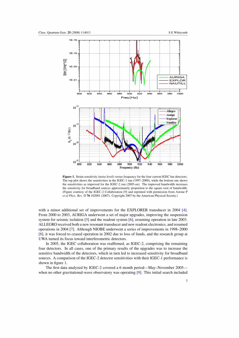
Figure 2. Strain sensitivity (noise level for a broadband source) versus time for the IGEC-2detectors for the six month period between May and November 2005. The detectors showedexcellent stability and up-time. (Figure courtesy of the IGEC-2 Collaboration [9] and reprintedwith permission from Astone P et al Phys. Rev. D 76 102001 (2007). Copyright 2007 by theAmerican Physical Society.)
data from AURIGA, EXPLORER and NAUTILUS; ALLEGRO data quality flags were delayedand it was decided to use ALLEGRO data only for follow-up of any interesting events. As aresult of the upgrades made after IGEC-1, the IGEC-2 detectors showed excellent duty factorand stability. During this period, the three analyzed detectors had an average duty factorof almost 90%, and the 180 days of observation produced 130 days of three-fold operation,almost as many as the earlier 4-year IGEC-1 data run. Figure 2 shows the stability and highduty factor for the IGEC-2 detectors during this 180 days period. The collaboration currentlyhas a substantially larger set of data from 2006 to analyze. It is hoped that the data fromALLEGRO will be included in this analysis.
In spite of these successes, IGEC-2 has a cloudy future. Interferometric detectors (mostnotably LIGO) have now passed the sensitivity of bar detector and are beginning to approachthem in observation time, making upper limits from generalized searches with the IGECbar detectors significantly less interesting. (Note: searches for gravitational waves fromextraordinary astrophysical events, such as a near-by supernova, can still be of great interest,particularly given less than full time coverage by interferometric detectors.) As a result, thesupporting agencies have begun to limit or reduce the funding for bar detectors. NIOBEceased operations in 2002 and it did not join IGEC-2. More recently, it was announcedin April 2007 that the ALLEGRO detector would also soon cease operation, so its furtherparticipation in IGEC-2 will be restricted to previously collected data. AURIGA, EXPLORERand NAUTILUS continue to operate, but their continued funding will be evaluated annually.
3. Interferometric detectors: achieving their promise
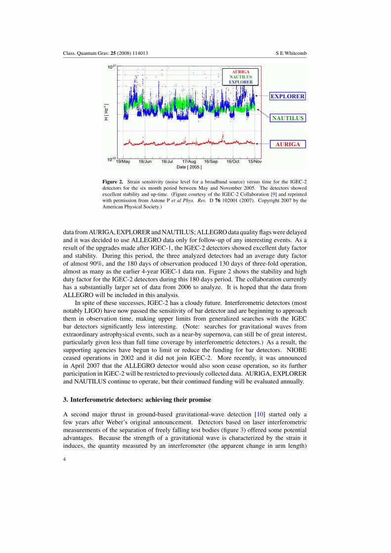
A second major thrust in ground-based gravitational-wave detection [10] started only afew years after Weber’s original announcement. Detectors based on laser interferometricmeasurements of the separation of freely falling test bodies (figure 3) offered some potentialadvantages. Because the strength of a gravitational wave is characterized by the strain itinduces, the quantity measured by an interferometer (the apparent change in arm length)
4
Class. Quantum Grav. 25 (2008) 114013 S E Whitcomb
Figure 3. Schematic diagram of an interferometric gravitational-wave detector. This sketch showsa Fabry–Perot Michelson interferometer with power-recycling, the configuration used by LIGO,Virgo and TAMA. (Figure courtesy of the LIGO Laboratory.)
grows proportional to arm length, and thus increasing the arm length (up to one quarter of thegravitational wavelength) increases the signal relative to many of the important noise sources.In addition, the nature of an interferometer makes these detectors naturally cover a broadrange of frequencies. However, there has been much technology to be developed to reachthis promise, and the large detectors are both expensive and lengthy to build and commission.It is only in the last few years that the large interferometric detectors have taken the lead insensitivity.
All of the current interferometric detectors are Michelson interferometers and mostincorporate resonant Fabry–Perot cavities in the arms to enhance the sensitivity. A highlystabilized laser beam strikes the beamsplitter and is directed to the two arms. Theinterferometer is operated with constructive interference on the side of the beamsplitter whichis illuminated by the laser (sending the light from the interferometer back toward the laser)and destructive interference on the other side where a photodetector reads out the differencein arm length (often called the ‘antisymmetric port’). A partially transmitting mirror placedin the incident laser beam creates a second (compound) cavity, allowing the laser powerincident on the beamsplitter to build up and increase the sensitivity of the interferometer. Theinterferometer mirrors are suspended in vacuum on thin wires from vibration-isolated platformsto protect them from non-gravitational forces which might interfere with the measurement.A complex control system maintains proper positioning and alignment of the optics. Thisconfiguration, dubbed a Fabry–Perot Michelson interferometer with power-recycling, is thebasis for almost all current interferometric detectors.
The largest of these efforts is the Laser Interferometer Gravitational-wave Observatory(LIGO), located in the US [11, 12]. LIGO comprises two 4 km long L-shaped facilities, oneat Hanford, Washington and the other in Livingston, Louisiana. The site at Hanford alsohas a 2 km detector sharing the same vacuum system. The LIGO detectors have the Fabry–Perot Michelson configuration with power-recycling. The laser is a 10 W Nd: YAG laseroperating at 1.06 µm. The mirrors have a simple pendulum suspension with metal wires froma four-stage passive isolation system. The LIGO detectors were designed so that the dominant
5
Class. Quantum Grav. 25 (2008) 114013 S E Whitcomb
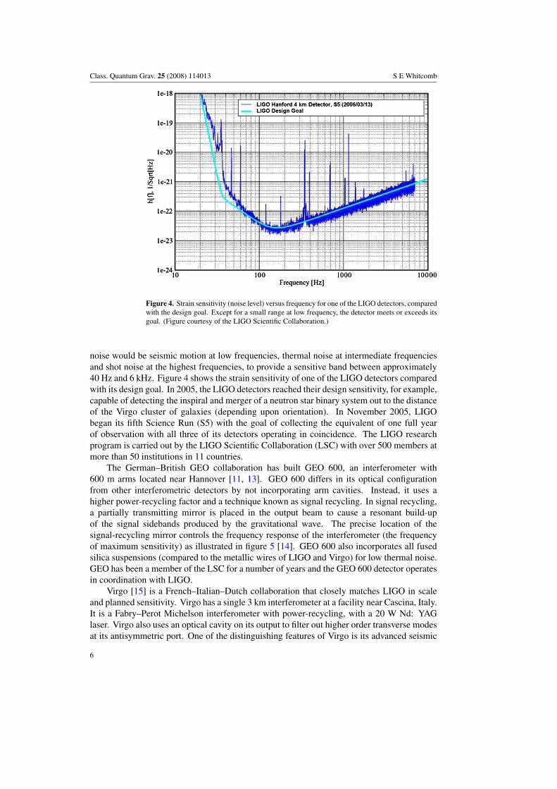
Figure 4. Strain sensitivity (noise level) versus frequency for one of the LIGO detectors, comparedwith the design goal. Except for a small range at low frequency, the detector meets or exceeds itsgoal. (Figure courtesy of the LIGO Scientific Collaboration.)
noise would be seismic motion at low frequencies, thermal noise at intermediate frequenciesand shot noise at the highest frequencies, to provide a sensitive band between approximately40 Hz and 6 kHz. Figure 4 shows the strain sensitivity of one of the LIGO detectors comparedwith its design goal. In 2005, the LIGO detectors reached their design sensitivity, for example,capable of detecting the inspiral and merger of a neutron star binary system out to the distanceof the Virgo cluster of galaxies (depending upon orientation). In November 2005, LIGObegan its fifth Science Run (S5) with the goal of collecting the equivalent of one full yearof observation with all three of its detectors operating in coincidence. The LIGO researchprogram is carried out by the LIGO Scientific Collaboration (LSC) with over 500 members atmore than 50 institutions in 11 countries.
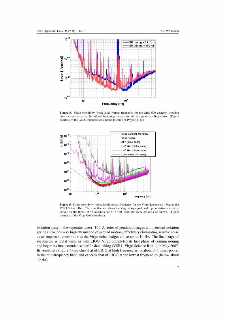
The German–British GEO collaboration has built GEO 600, an interferometer with600 m arms located near Hannover [11, 13]. GEO 600 differs in its optical configurationfrom other interferometric detectors by not incorporating arm cavities. Instead, it uses ahigher power-recycling factor and a technique known as signal recycling. In signal recycling,a partially transmitting mirror is placed in the output beam to cause a resonant build-upof the signal sidebands produced by the gravitational wave. The precise location of thesignal-recycling mirror controls the frequency response of the interferometer (the frequencyof maximum sensitivity) as illustrated in figure 5 [14]. GEO 600 also incorporates all fusedsilica suspensions (compared to the metallic wires of LIGO and Virgo) for low thermal noise.GEO has been a member of the LSC for a number of years and the GEO 600 detector operatesin coordination with LIGO.
Virgo [15] is a French–Italian–Dutch collaboration that closely matches LIGO in scaleand planned sensitivity. Virgo has a single 3 km interferometer at a facility near Cascina, Italy.It is a Fabry–Perot Michelson interferometer with power-recycling, with a 20 W Nd: YAGlaser. Virgo also uses an optical cavity on its output to filter out higher order transverse modesat its antisymmetric port. One of the distinguishing features of Virgo is its advanced seismic
6
Class. Quantum Grav. 25 (2008) 114013 S E Whitcomb
Figure 5. Strain sensitivity (noise level) versus frequency for the GEO 600 detector, showinghow the sensitivity can be tailored by tuning the position of the signal-recycling mirror. (Figurecourtesy of the GEO Collaboration and the Institute of Physics [14].)
Figure 6. Strain sensitivity (noise level) versus frequency for the Virgo detector as it begins theVSR1 Science Run. The smooth curve shows the Virgo design goal, and representative sensitivitycurves for the three LIGO detectors and GEO 600 from the same era are also shown. (Figurecourtesy of the Virgo Collaboration.)
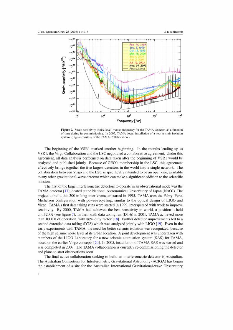
isolation system, the superattenuator [16]. A series of pendulum stages with vertical isolationsprings provides very high attenuation of ground motion, effectively eliminating seismic noiseas an important contributor to the Virgo noise budget above about 10 Hz. The final stage ofsuspension is metal wires as with LIGO. Virgo completed its first phase of commissioningand began its first extended scientific data taking (VSR1, Virgo Science Run 1) in May 2007.Its sensitivity (figure 6) matches that of LIGO at high frequencies, is about 3–5 times poorerin the mid-frequency band and exceeds that of LIGO at the lowest frequencies (below about40 Hz).
7
Class. Quantum Grav. 25 (2008) 114013 S E Whitcomb
Figure 7. Strain sensitivity (noise level) versus frequency for the TAMA detector, as a functionof time during its commissioning. In 2005, TAMA began installation of a new seismis isolationsystem. (Figure courtesy of the TAMA Collaboration.)
The beginning of the VSR1 marked another beginning. In the months leading up toVSR1, the Virgo Collaboration and the LSC negotiated a collaborative agreement. Under thisagreement, all data analysis performed on data taken after the beginning of VSR1 would beanalyzed and published jointly. Because of GEO’s membership in the LSC, this agreementeffectively brings together the five largest detectors in the world into a single network. Thecollaboration between Virgo and the LSC is specifically intended to be an open one, availableto any other gravitational-wave detector which can make a significant addition to the scientificmission.
The first of the large interferometric detectors to operate in an observational mode was theTAMA detector [17] located at the National Astronomical Observatory of Japan (NAOJ). Theproject to build this 300 m long interferometer started in 1995. TAMA uses the Fabry–PerotMichelson configuration with power-recycling, similar to the optical design of LIGO andVirgo. TAMA’s first data taking runs were started in 1999, interspersed with work to improvesensitivity. By 2000, TAMA had achieved the best sensitivity in world, a position it helduntil 2002 (see figure 7). In their sixth data taking run (DT-6) in 2001, TAMA achieved morethan 1000 h of operation, with 86% duty factor [18]. Further detector improvements led to asecond extended data taking (DT8) which was analyzed jointly with LIGO [19]. Even in theearly experiments with TAMA, the need for better seismic isolation was recognized, becauseof the high seismic noise level at its urban location. A joint development was undertaken withmembers of the LIGO Laboratory for a new seismic attenuation system (SAS) for TAMA,based on the earlier Virgo concepts [20]. In 2005, installation of TAMA SAS was started andwas completed in 2007. The TAMA collaboration is currently re-commissioning the detectorand plans to start observations soon.
The final active collaboration seeking to build an interferometric detector is Australian.The Australian Consortium for Interferometric Gravitational Astronomy (ACIGA) has begunthe establishment of a site for the Australian International Gravitational-wave Observatory
8
Class. Quantum Grav. 25 (2008) 114013 S E Whitcomb
Figure 8. Design noise level for the Advanced LIGO detectors compared with the initial LIGOdesign goal. The advanced LIGO noise curve shown is the sum of numerous contributions: seismicnoise, suspension thermal noise, mirror thermal noise, quantum noise and gravitational gradients.(Figure courtesy of the LIGO Scientific Collaboration.)
(AIGO) [21] on an 8 km by 8 km parcel at Gingin, Western Australia (70 km north of Perth).Construction began in 1999 and a substantial facility (including roads, clean room laboratories,workshops and a visitor accommodation) is now in place. An education and astronomy centeropened in 2003. Currently, they are operating an 80 m long interferometer for testing theeffects of high optical power, in support of the Advanced LIGO program [22].
4. Looking toward the future
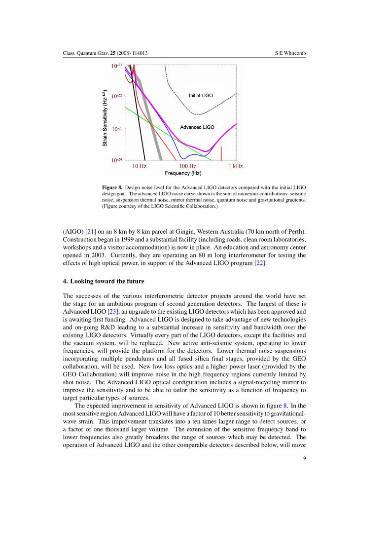
The successes of the various interferometric detector projects around the world have setthe stage for an ambitious program of second generation detectors. The largest of these isAdvanced LIGO [23], an upgrade to the existing LIGO detectors which has been approved andis awaiting first funding. Advanced LIGO is designed to take advantage of new technologiesand on-going R&D leading to a substantial increase in sensitivity and bandwidth over theexisting LIGO detectors. Virtually every part of the LIGO detectors, except the facilities andthe vacuum system, will be replaced. New active anti-seismic system, operating to lowerfrequencies, will provide the platform for the detectors. Lower thermal noise suspensionsincorporating multiple pendulums and all fused silica final stages, provided by the GEOcollaboration, will be used. New low loss optics and a higher power laser (provided by theGEO Collaboration) will improve noise in the high frequency regions currently limited byshot noise. The Advanced LIGO optical configuration includes a signal-recycling mirror toimprove the sensitivity and to be able to tailor the sensitivity as a function of frequency totarget particular types of sources.
The expected improvement in sensitivity of Advanced LIGO is shown in figure 8. In themost sensitive region Advanced LIGO will have a factor of 10 better sensitivity to gravitational-wave strain. This improvement translates into a ten times larger range to detect sources, ora factor of one thousand larger volume. The extension of the sensitive frequency band tolower frequencies also greatly broadens the range of sources which may be detected. Theoperation of Advanced LIGO and the other comparable detectors described below, will move
9
Class. Quantum Grav. 25 (2008) 114013 S E Whitcomb
the field from gravitational-wave detection to gravitational-wave astrophysics. Constructionof Advanced LIGO is planned to start in 2008, start with installation in the existing LIGOvacuum system beginning in 2011.
This schedule for Advanced LIGO leaves more than 3 years before the initial LIGOdetectors must be removed. This is enough time for one significant set of enhancementsto the initial LIGO detectors. This project, called Enhanced LIGO, aims for a factor of 2improvement in sensitivity over initial LIGO, corresponding to a factor of 8 in the volumeof the universe observed. The main technical elements of Enhanced LIGO include a higherpower laser (35 W versus the current 10 W), and a change in the readout scheme for theinterferometer. The readout of the interferometer will be changed from an rf scheme usingphase modulated sidebands to a dc readout scheme using a tiny offset from the dc fringeminimum. An output modecleaner will be added to eliminate higher order transverse modesfrom the light incident on the photodetectors. Enhanced LIGO will give early tests of someAdvanced LIGO hardware and techniques, thus reducing the risk and raising the probabilityof success of Advanced LIGO.
Virgo has a similar two-phase plan for future upgrades [24]. Following the completion oftheir current data taking (VSR1) in late 2007, the Virgo Collaboration will undertake Virgo+,a set of improvements designed to give at least a factor of 2 sensitivity increase over nominalinitial Virgo design goal. Virgo+ is an intermediate step toward Advanced Virgo, which willhave a ten times sensitivity increase over nominal Virgo. Building and commissioning Virgo+will continue upto mid 2009, to be followed by another extended data run in coincidence withEnhanced LIGO, lasting into late 2010. Advanced Virgo fabrication will be carried on inparallel with Virgo+ commissioning and operation and Advanced Virgo installation will beginin 2011.
The final technical scope of Virgo+ and Advanced Virgo is still not fully determined.Current plans for Virgo+ include an increase in laser power, a change in the finesse of thearm cavities, the addition of a system to compensate for optical heating in the mirrors, andelimination of several sources of excess noise at low frequencies. Advanced Virgo [24] willinclude a major upgrade for all nearly all Virgo subsystems. Larger mirrors with improvedcoatings will be installed to reduce radiation pressure noise and coating thermal noise. Still-higher laser power will be used, and the thermal compensation systems installed for Virgo+will be upgraded to operate at the higher level. A signal-recycling mirror will be added. TheVirgo superattenuator seismic isolation will be retained but the final stage suspension will beupgraded to an all fused-silica configuration. The enabling R&D for these upgrades is alreadyunderway, and the crucial design decisions will be made in late 2007.
GEO 600 will be upgraded through a project known as GEO-HF [25]. GEO’s upgradeplans are constrained by its shorter arm length and the inability to expand its site because ofgeographic limits (a river). These constraints mean that it would be unlikely that GEO canmatch the sensitivity of Advanced LIGO and Advanced Virgo at low frequencies. As a result,GEO upgrades will concentrate on improving its sensitivity at high frequencies, near 1 kHz.Potential sources of gravitational waves in the frequency band from 1 to 5 kHz include burstsof gravitational waves from supernovas, normal modes of neutron stars and quasi-normalmodes of stellar mass black holes. The GEO-HF laser will be upgraded to a higher powerversion, similar to the one being developed by the GEO collaboration for Advanced LIGO.Signal recycling will be retained and may be tuned to offer a narrower bandwidth. Newmirrors may be installed to reduce thermal noise. A second goal of GEO-HF is to pioneeradvanced techniques which may be applied later to other large interferometers. This mightinclude use of squeezed states of light to enhance sensitivity [26]. These upgrades will be
10
Class. Quantum Grav. 25 (2008) 114013 S E Whitcomb
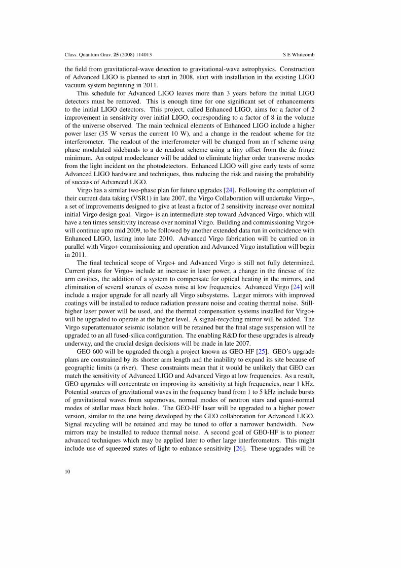
Figure 9. Schematic drawing of the cryogenic suspension planned for LCGT. (Figure courtesy ofthe LCGT Collaboration.)
implemented as opportunities present themselves between now and 2010, in coordination withthe run planning for LIGO and Virgo.
The Japanese groups who designed and built TAMA have proposed an ambitious newdetector: the large-scale cryogenic gravitational-wave telescope (LCGT) [27]. LCGT wouldbe located at an underground site (the Kamioka mine) and will have 3 km long arms. It willhave the same basic optical layout as TAMA (Fabry–Perot Michelson with power-recycling),but resonant sideband extraction [28] will be used to increase sensitivity and to be able to tailorthe frequency response. Two parallel interferometers will be installed in a common vacuumenvelope, similar to the LIGO Hanford site. The main technical feature which distinguishesLCGT from Advanced LIGO and Advanced Virgo is that the LCGT mirrors will be cooledto cryogenic temperatures to reduce thermal noise (figure 9). The seismic isolation/mirrorsuspension system will be similar to the upgraded system seismic attenuation system (SAS)recently installed in TAMA, and much progress has been made in the development of cryo-coolers which can extract the required heat load without introducing unwanted vibrations [29].The detector will incorporate a suspension point interferometer to isolate from low frequencyseismic motion. CLIO, a 100 m interferometer to demonstrate the cryogenic technology andthe benefits of an underground location has been built in Kamioka mine [27]. A proposalfor 2008 funding LCGT has been recently turned down (between the presentation of this talkand the preparation of the proceedings paper) and the LCGT collaboration is considering itsfurther options.
ACIGA is pursuing funding to expand the Australian International Gravitational-waveObservatory (AIGO) to kilometer scales. The location in Western Australia offers strongscience benefits in the context of an international network. The long baseline to planneddetectors in the US and Europe improves the effective angular resolution for bursts ofgravitational waves (such as might be emitted by the merger of a neutron star binary) fromthe order of a degree to about 10 arc minutes [30]. With this resolution, it will be possible tomake unique galaxy identifications out to nearly 100 Mpc. The AIGO goal is to have 5 km
11
Class. Quantum Grav. 25 (2008) 114013 S E Whitcomb
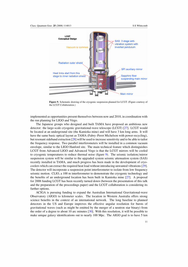
Figure 10. Possible noise level for the Einstein Gravitational-Wave Telescope compared with theother current and planned detectors. (Figure courtesy of the ET Collaboration.)
arms and to be sensitive to inspirals in the range ∼250 Mpc. The Western AustralianGovernment has provided seed funding for AIGO by establishing a Centre of Excellence forGravitational Astronomy and the Australian Consortium is actively seeking funding includingnew international partners in this project.
For the more distant future, the interferometric detector community is contemplatinga detector called the Einstein Gravitational-Wave Telescope (ET). The sensitivity goals forET are shown in figure 10, aiming at another factor of 10 sensitivity beyond AdvancedLIGO and Advanced Virgo, as well as a much lower frequency capability. The ET baselineconcept incorporates two of the innovative features of LCGT: an underground location andcryogenic cooling. The underground location is important to reduce seismic noise and toreduce gravity gradient noise. Cryogenic cooling of mirrors offers the possibility of lowerthermal noise. Ultra-low frequency suspensions would be required to take advantage ofthe lower thermal noise, and quantum non-demolition techniques [26, 31] are likely to beemployed. Configurations under consideration for ET include triangular ones in addition tothe L’s of the first- and second-generation interferometric detectors. Cost considerations willbe important and the current studies are constrained to have an overall beam tube length of∼30 km. Currently, ET is the subject of a design study funded by the European Commission,but it is expected that the broader ground-based interferometric detector community will beinvolved to some extent.
Finally, even as the current generation of cryogenic bar detectors is reaching its end,there are ideas for new directions. The AURIGA group has been exploring a new concept foracoustic gravitational-wave detectors that they call DUAL [32]. DUAL envisages two nestedmechanical resonators (shown in the right portion of figure 11 as two cylinders). In the regionbetween the main resonant modes of the two cylinders, the motion in the gap between the twomasses is out of phase. By combining the output of a set of non-resonant transducers placedin the gap, on can read the differential deformations of the cylinders, throughout the frequencyband between the two resonances. By combining the outputs of multiple sensors in the correctway, the result is a system that is sensitive only to the motion corresponding to gravitational
12
Class. Quantum Grav. 25 (2008) 114013 S E Whitcomb
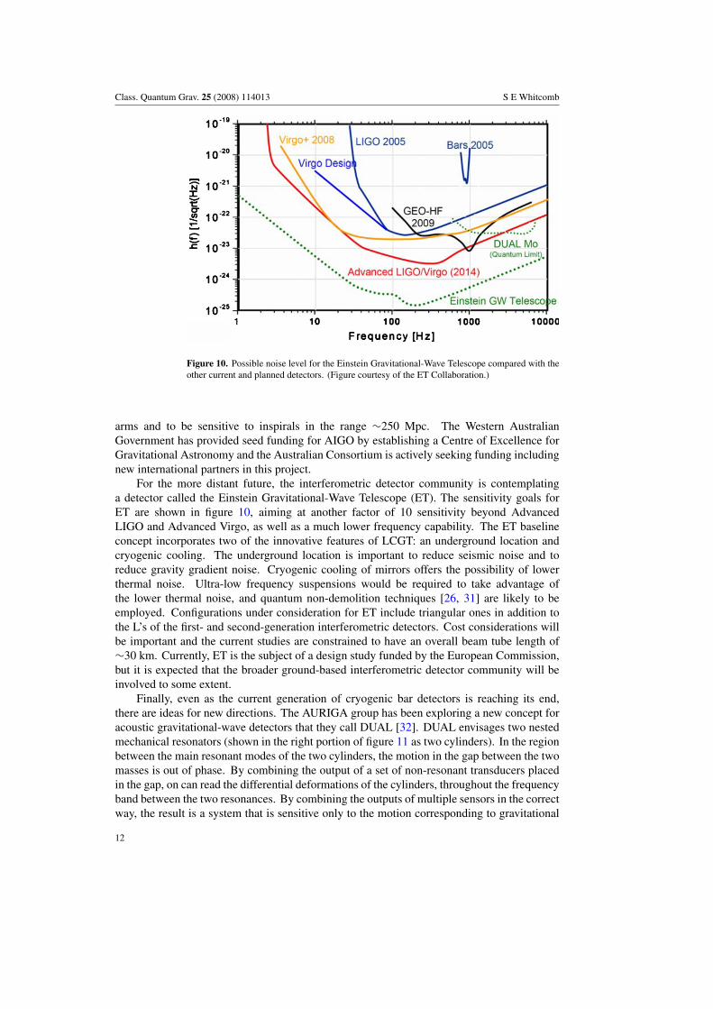
Figure 11. Illustration showing the DUAL detector operation. The two nested oscillators inthe lower part of the figure illustrate how it operates: above and below both resonances the twooscillators respond to a gravitational wave with the same phase, but between the two resonancesthey respond out of phase. Transducers in the gap will sense the differential motion. (Figurecourtesy of the DUAL Collaboration.)
waves, and which reduces overall thermal noise by rejecting the contribution of modes whichare not sensitive to gravitational waves.
There are a number of questions which must be resolved before construction of a full-scaleDUAL detector could begin, and research is underway to address many of these. Alternatephysical configurations to the cylindrical one in figure 11 are possible, and several materialsare being evaluated for their physical properties and manufacturability. The selection ofthe readout is critical; large area readouts are important for back-action reduction andmode selectivity. Current candidates include optical readouts [33] and capacitive readoutswith SQUID amplifiers. If the R&D for these detectors is successful, they may providecomplementary coverage to the large interferometers in the frequency band from 1 to 5 kHz.
5. Final thoughts
Over the past decade, we have seen remaining bar detectors around the world mature andcoalesce into a coherent network. Since the last International Conference on GeneralRelativity & Gravitation, we have also seen interferometric detectors equal and pass thebar detectors in sensitivity, taking the leadership in the field of ground-based gravitational-wave detection. Interferometers are now showing the sensitivities and bandwidths that theypromised, and the interferometer projects have begun to organize themselves into a globalnetwork. Improvements to the existing interferometric detectors are underway, and nextgeneration detectors will soon be under construction. Together these improvements offer toincrease our ‘science’ capability by a factor of 1000 or more. The day when we see the firstdirect detection of gravitational waves draws steadily nearer.
13
Class. Quantum Grav. 25 (2008) 114013 S E Whitcomb
Acknowledgments
I would like to thank the Gravitational Wave International Committee (GWIC), the scientificorganizing committee for the Amaldi meetings, for the invitation to give this talk. As with anytalk which summarizes such a broad field, I cannot list all of the individuals who contributedto the work described here, nor even all who contributed to the material I have presented. Butyou know who you are, so do I, and I thank you. Of course, all responsibility for the over-simplifications, the omissions and the out-right errors contained herein falls on my shoulders.I gratefully acknowledge the support of the National Science Foundation under cooperativeagreement no. PHY-0107417.
References
[1] Weber J 1969 Phys. Rev. Lett. 22 1320–4Weber J 1970 Phys. Rev. Lett. 25 180–4
[2] Allen Z et al 2000 Phys. Rev. Lett. 85 5046[3] Astone P et al 2003 Phys. Rev. D 68 022001[4] Astone P et al 2003 Phys. Rev. Lett. 91 111101
Astone P et al 2006 Class. Quantum Grav. 23 S57[5] Bignotto M, Bonaldi M, Cerdonio M, Conti L, Penasa F, Prodi G, Soranzo G, Taffarello L and Zendri J 2005
Rev. Sci. Instrum. 76 084502[6] Baggio L et al 2005 Phys. Rev. Lett. 94 241101[7] McHugh M P, Johnson W W, Hamilton W O, Hanson J, Heng I S, McNeese D, Miller P, Nettles D, Weaver J
and Zhang P 2005 Class. Quantum Grav. 22 S965[8] Coward D, Blair D, Clay R and Mazzitell G 2002 Class. Quantum Grav. 19 1871–5[9] Astone P et al 2007 Phys. Rev. D 76 102001
[10] Weiss R Quarterly Progress Report 105, Research Laboratory of Electronics, MIT, April 1972Moss G F, Miller L R and Forward R L 1971 Appl. Opt. 10 2495–8
[11] Abbott B et al (LIGO Scientific Collaboration) 2004 Nucl. Instrum. Methods A 517 154–79[12] Sigg D (for the LIGO Scientific Collaboration) 2006 Class. Quantum Grav 23 S51–6
Sigg D (for the LIGO Scientific Collaboration) 2007 Status of the LIGO detectors Class. Quantum Grav. 25114041
[13] Grote H (for the LIGO Scientific Collaboration) The Status of GEO 600 Class. Quantum Grav. 25 114043[14] Willke B (for the LIGO Scientific Collaboration) 2007 Class. Quantum Grav. 24 S389–97[15] Acernese F et al 2004 Class. Quantum Grav. 21 S385–94
Acernese F et al 2007 Class. Quantum Grav. 24 S381–8[16] Del Fabbro R, Di Virgilio A, Giazotto A, Kautzky H, Montelatici V and Passuello D 1987 Phys. Lett.
A 124 253–7Braccini S et al 1995 Phys. Lett. A 199 307–14Beccaria M et al 1997 Instrum. Methods A 394 397–408Braccini et al 2005 Astroparticle Phys. 23 557–65
[17] Ando M et al 2001 Phys. Rev. Lett. 86 3950Kuroda K (for the TAMA Collaboration) 2007 The current status of TAMA Proc. Rencontres de Moriond,
Gravitational Waves and Experimental Gravity (La Thuile, Val d’Aosta, Italy, March 11–18, 2007)at press
[18] Takahashi H et al 2004 Phys. Rev. D 70 042003[19] Abbott B et al (LIGO Scientific Collaboration) and Akutsu T et al (TAMA Collaboration) 2005 Phys. Rev.
D 72 122004Abbott B et al (LIGO Scientific Collaboration) and Akutsu T et al (TAMA Collaboration) 2006 Phys. Rev.
D 73 102002[20] Marka S et al 2002 Class. Quantum Grav. 19 1605–14
Takamori A et al 2002 Class. Quantum Grav. 19 1615–21[21] Zhao C et al 2006 J. Phys.: Conf. Ser. 32 368–73[22] Ju L et al 2004 Class. Quantum Grav. 21 S887–93
Barriga P et al 2005 Class. Quantum Grav. 22 S199–208
14
Class. Quantum Grav. 25 (2008) 114013 S E Whitcomb
[23] Fritschel P 2003 Second generation instruments for the Laser Interferometer Gravitational Wave Observatory(LIGO) Gravitational-Wave Detection vol 4856 ed M Cruise and P Saulson (Bellingham, WA: SPIE) 282–91
Robertson N A et al 2004 Gravitational wave and particle astrophysics detectors Proc. SPIE ed Hough J andSanders G 5500 81–91
Miyakawa O et al 2004 Gravitational wave and particle astrophysics detectors Proc. SPIE ed Hough J andSanders G H 5500 pp 92–104
[24] The Virgo Collaboration 2007 Advanced Virgo Conceptual Design Virgo Report VIR 042A 07,http://wwwcascina.virgo.infn.it/advirgo/docs/AdV Design.pdf
[25] Willke B et al 2006 Class. Quantum Grav. 23 S207–14[26] McKenzie K, Grosse N, Bowen W P, Whitcomb S E, Gray M B, McClelland D E and Lam P K 2004 Phys. Rev.
Lett. 93 161105Vahlbruch H, Chelkowski S, Hage B, Franzen A, Danzmann K and Schnabel R 2006 Phys. Rev. Lett. 97 011101
[27] Uchiyama T et al 2004 Class. Quantum Grav. 21 S1161–72Kuroda K (for the CLIO/LCGT Collaboration) 2007 CLIO and LCGT Proc. Rencontres de Moriond,
Gravitational Waves and Experimental Gravity (La Thuile, Val d’Aosta, Italy, March 11–18, 2007) atpress
[28] Mizuno J, Strain K A, Nelson P G, Chen J M, Schilling R, Ruediger A, Winkler W and Danzmann K 1993Phys. Lett. A 175 273
Strain K A et al 2003 Appl. Opt. 42 1244Miyakawa O et al 2006 Phys. Rev. D 74 022001Kawazoe F, Sato S, Leonhardt V, Miyakawa O, Morioka T, Nishizawa A, Yamazaki T, Mitsuhiro Fukushima M,
Kawamura S and Sugamoto A 2007 Experimental investigation of a control scheme for a tuned resonantsideband extraction interferometer for next-generation gravitational-wave detectors (submitted to Class.Quantum Grav.)
[29] Li R et al 2004 Class. Quantum Grav. 21 S1005–8[30] Wen L, Howell E, Coward D and Blair D 2007 Proc. Rencontres de Moriond, Gravitational Waves and
Experimental Gravity (La Thuile, Val d’Aosta, Italy, March 11–18, 2007) at press[31] Kimble H J, Levin Yu, Matsko A B, Thorne K S and Vyatchanin S P 2002 Phys. Rev. D 65 022002
Purdue P 2002 Phys. Rev. D 66 022001Purdue P and Chen Y 2002 Phys. Rev. D 66 122004Chen Y 2003 Phys. Rev. D 67 122004
[32] Cerdonio M, Conti L, Lobo J A, Ortolan A, Taffarello L and Zendri J P 2001 Phys. Rev. Lett. 87 031101Bonaldi M, Cerdonio M, Conti L, Pinard M, Prodi G A, Taffarello L and Zendri J P 2003 Phys. Rev. 68 102004
[33] Marin F, Conti L and De Rosa M 2003 Phys. Lett. A 309 15–23
15