Embed Size (px)
Citation preview
Ground-Fault Protection and Ground-Conductor Monitoringfor Portable Mine-Power Cables
G.E. Paulson, P. Eng.and
J.J. Dudiak, P. Eng. Littelfuse Startco
3714 Kinnear PlaceSaskatoon, Saskatchewan
Canada S7P 0A6
Abstract—Resistance grounding offers many of the advantagesof both solidly grounded and ungrounded systems. This paperdescribes a practical approach to the selection of a groundingresistor let-through current and the operating value of theground-fault relays. When portable mine-power cables areused, ground conductors must be monitored. It is suggestedthat ground-conductor monitors should be resistance sensitiveand that the resistance trip-level should be determined by theallowable ground-fault voltage and the operating value of theground-fault relays.
I. SYSTEM GROUNDING METHODS
A solidly grounded system is a system in which the wyepoint of the supply transformer is connected solidly toground. This configuration has the advantage of a fixedphase-to-ground voltage; however, a solidly groundedsystem has several disadvantages. When a ground faultoccurs, high point-of-fault damage can result as poweravailable to the fault is limited only by the systemimpedance. Also, ground-fault voltage, which is equal to theproduct of the fault current and the ground impedance, canexceed 100 V when a high fault current is available.
An ungrounded system is a system in which no point inthe system is intentionally grounded. Grounding occurs onlythrough system capacitance to ground. An ungroundedsystem has the advantage that there is no point-of-faultdamage and the system can continue to operate with onephase faulted. The chief disadvantage of an ungroundedsystem is that intermittent or arcing faults can produce hightransient voltages to ground. These voltages are impressedon the phase conductors throughout the system until theinsulation at the weakest point in the system (often motorwindings) breaks down.
A resistance-grounded system is a system in which thetransformer neutral is connected to ground through acurrent-limiting resistor. This configuration has theadvantages of both previous systems. Transient-overvoltages are eliminated because the neutral-grounding
resistor provides a discharge path for the systemcapacitance. Also, the neutral-grounding resistor limitscurrent available to the fault and this minimizes point-of-fault damage and controls ground-fault voltage. In somecases, a resistance-grounded system can be allowed tooperate with one phase faulted.
II. SYSTEM CHARGING CURRENT
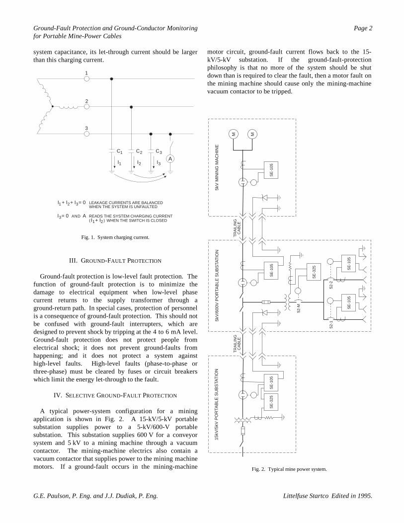
Charging current is defined as that current which will flowinto the grounding connection when one phase of anungrounded system is faulted to ground [1]. In an idealungrounded system, no current will flow if one phase isgrounded because the circuit is not complete. In an actualungrounded system, current will flow as shown in Fig. 1.The capacitors represent the total distributed capacitance ofthe system and are made up of the capacitance to ground ofcables, motor windings, and other components such assurge-protection capacitors which are deliberately connectedfrom the phases to ground. Power-factor-correctioncapacitors are connected phase to phase and do notcontribute significantly to the capacitance to ground.
When designing a new system, charging current can beestimated from data for the system components. On anexisting system, charging current can be measured as shownin Fig. 1. With the system powered, the switch is closed andthe ammeter reading is taken. The ammeter reading is thevectorial sum of I1 + I2 and is equal to the system chargingcurrent. The system charging current should be the same foreach phase; however, the charging current for each phaseshould be measured. For safety reasons, a fast-acting fuseand a current-limiting resistor should be connected in serieswith the ammeter when performing this test. The followingrule-of-thumb can be used to estimate charging current: forlow-voltage systems, a typical value is 1 A per 2000 kVA;and for medium-voltage systems a typical value is 1 A per1000 kVA [2, 3]. Consequently, charging current will be inthe range of 0.5 to 2.0 A for most trailing-cable applications.If a neutral-grounding resistor is used to discharge the
2 egaPgnirotinoM rotcudnoC-dnuorG dna noitcetorP tluaF-dnuorGfor Portable Mine-Power Cables
.5991 ni detidE Littelfuse Startco .gnE .P ,kaiduD .J.J dna .gnE .P ,nosluaP .E.G
system capacitance, its let-through current should be largerthan this charging current.
A
1
2
3
C C C
I
I + I + I = 0
I I1
1
1
2
2
2
3
3
3
1 2 3
LEAKAGE CURRENTS ARE BALANCEDWHEN THE SYSTEM IS UNFAULTED
I = 0 AND A READS THE SYSTEM CHARGING CURRENTI + I WHEN THE SWITCH IS CLOSED( )
Fig. 1. System charging current.
III. GROUND-FAULT PROTECTION
Ground-fault protection is low-level fault protection. Thefunction of ground-fault protection is to minimize thedamage to electrical equipment when low-level phasecurrent returns to the supply transformer through aground-return path. In special cases, protection of personnelis a consequence of ground-fault protection. This should notbe confused with ground-fault interrupters, which aredesigned to prevent shock by tripping at the 4 to 6 mA level.Ground-fault protection does not protect people fromelectrical shock; it does not prevent ground-faults fromhappening; and it does not protect a system againsthigh-level faults. High-level faults (phase-to-phase orthree-phase) must be cleared by fuses or circuit breakerswhich limit the energy let-through to the fault.
IV. SELECTIVE GROUND-FAULT PROTECTION
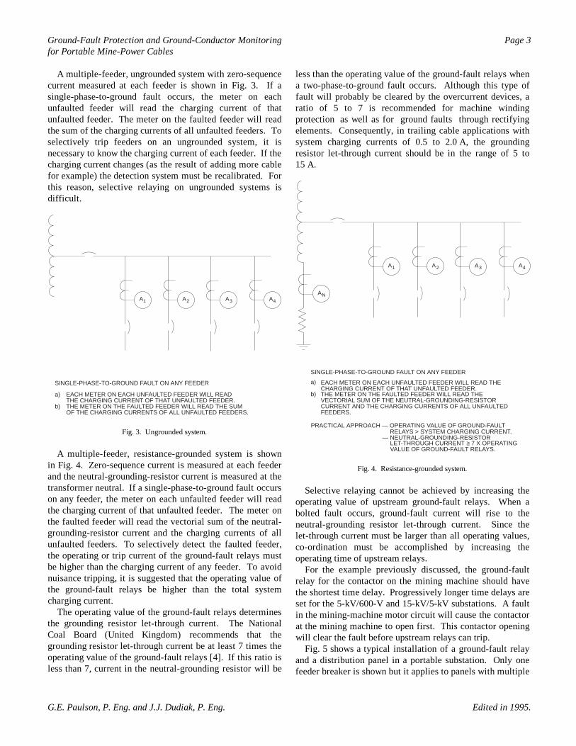
A typical power-system configuration for a miningapplication is shown in Fig. 2. A 15-kV/5-kV portablesubstation supplies power to a 5-kV/600-V portablesubstation. This substation supplies 600 V for a conveyorsystem and 5 kV to a mining machine through a vacuumcontactor. The mining-machine electrics also contain avacuum contactor that supplies power to the mining machinemotors. If a ground-fault occurs in the mining-machine
motor circuit, ground-fault current flows back to the 15-kV/5-kV substation. If the ground-fault-protectionphilosophy is that no more of the system should be shutdown than is required to clear the fault, then a motor fault onthe mining machine should cause only the mining-machinevacuum contactor to be tripped.
NOITAT
SB
US
ELB
ATR
OP
Vk5/Vk51
NOITAT
SB
US
ELB
ATR
OP
V006/Vk5
ENI
HC
AM
GNI
NIM
Vk5
MM
501-E
S501-
ES
523-E
S
501-E
S523-
ES
501-E
S501-
ES
GNILI
ART
ELB
AC
GNILI
ART
ELB
AC
M-25
1-252-25
Fig. 2. Typical mine power system.
3 egaPgnirotinoM rotcudnoC-dnuorG dna noitcetorP tluaF-dnuorGfor Portable Mine-Power Cables
.5991 ni detidE .gnE .P ,kaiduD .J.J dna .gnE .P ,nosluaP .E.G
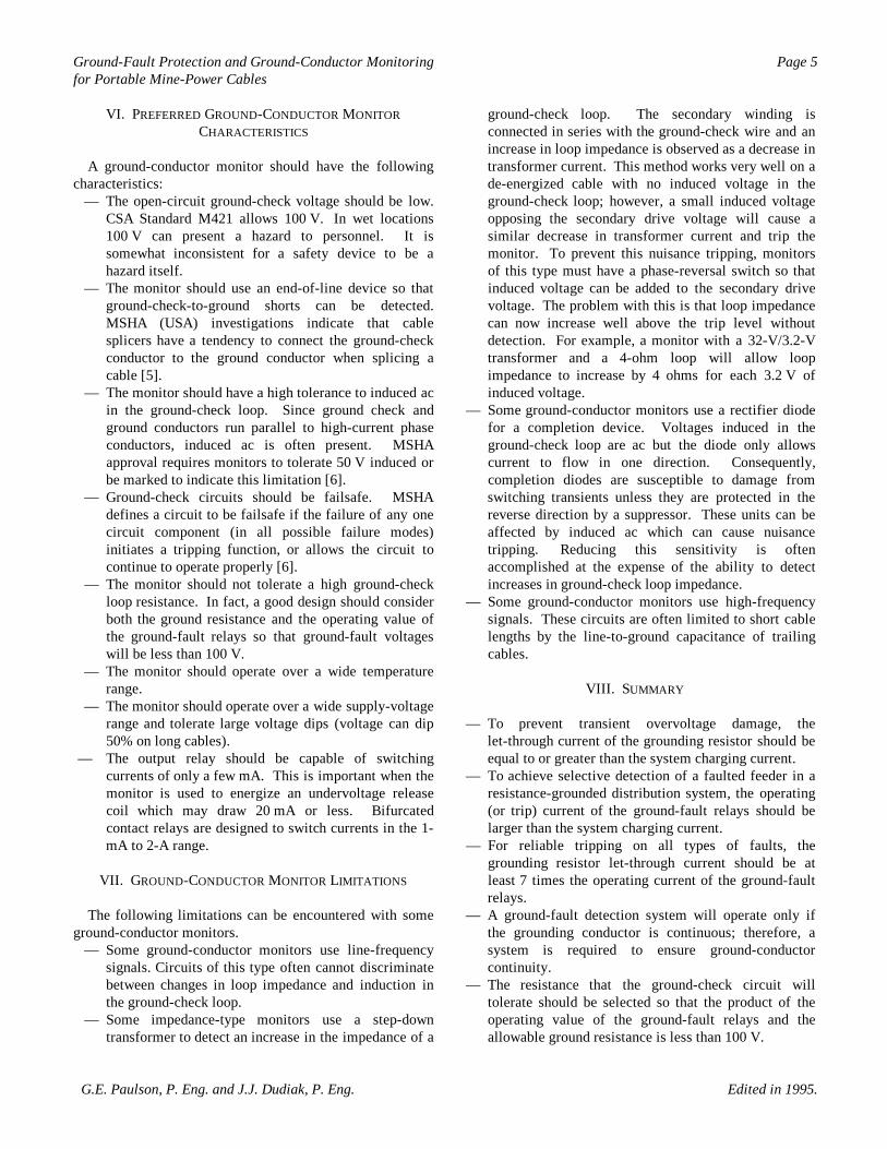
A multiple-feeder, ungrounded system with zero-sequencecurrent measured at each feeder is shown in Fig. 3. If asingle-phase-to-ground fault occurs, the meter on eachunfaulted feeder will read the charging current of thatunfaulted feeder. The meter on the faulted feeder will readthe sum of the charging currents of all unfaulted feeders. Toselectively trip feeders on an ungrounded system, it isnecessary to know the charging current of each feeder. If thecharging current changes (as the result of adding more cablefor example) the detection system must be recalibrated. Forthis reason, selective relaying on ungrounded systems isdifficult.
AAAA 4321
SINGLE-PHASE-TO-GROUND FAULT ON ANY FEEDER
EACH METER ON EACH UNFAULTED FEEDER WILL READTHE CHARGING CURRENT OF THAT UNFAULTED FEEDER.THE METER ON THE FAULTED FEEDER WILL READ THE SUMOF THE CHARGING CURRENTS OF ALL UNFAULTED FEEDERS.
a)
b)
Fig. 3. Ungrounded system.
A multiple-feeder, resistance-grounded system is shownin Fig. 4. Zero-sequence current is measured at each feederand the neutral-grounding-resistor current is measured at thetransformer neutral. If a single-phase-to-ground fault occurson any feeder, the meter on each unfaulted feeder will readthe charging current of that unfaulted feeder. The meter onthe faulted feeder will read the vectorial sum of the neutral-grounding-resistor current and the charging currents of allunfaulted feeders. To selectively detect the faulted feeder,the operating or trip current of the ground-fault relays mustbe higher than the charging current of any feeder. To avoidnuisance tripping, it is suggested that the operating value ofthe ground-fault relays be higher than the total systemcharging current.
The operating value of the ground-fault relays determinesthe grounding resistor let-through current. The NationalCoal Board (United Kingdom) recommends that thegrounding resistor let-through current be at least 7 times theoperating value of the ground-fault relays [4]. If this ratio isless than 7, current in the neutral-grounding resistor will be
less than the operating value of the ground-fault relays whena two-phase-to-ground fault occurs. Although this type offault will probably be cleared by the overcurrent devices, aratio of 5 to 7 is recommended for machine windingprotection as well as for ground faults through rectifyingelements. Consequently, in trailing cable applications withsystem charging currents of 0.5 to 2.0 A, the groundingresistor let-through current should be in the range of 5 to15 A.
AAAA
A
4321
N
SINGLE-PHASE-TO-GROUND FAULT ON ANY FEEDERa)
b)
PRACTICAL APPROACH — OPERATING VALUE OF GROUND-FAULTRELAYS > SYSTEM CHARGING CURRENT.
— NEUTRAL-GROUNDING-RESISTORLET-THROUGH CURRENT 7 X OPERATINGVALUE OF GROUND-FAULT RELAYS.
EACH METER ON EACH UNFAULTED FEEDER WILL READ THECHARGING CURRENT OF THAT UNFAULTED FEEDER.THE METER ON THE FAULTED FEEDER WILL READ THEVECTORIAL SUM OF THE NEUTRAL-GROUNDING-RESISTORCURRENT AND THE CHARGING CURRENTS OF ALL UNFAULTEDFEEDERS.
≥
Fig. 4. Resistance-grounded system.
Selective relaying cannot be achieved by increasing theoperating value of upstream ground-fault relays. When abolted fault occurs, ground-fault current will rise to theneutral-grounding resistor let-through current. Since thelet-through current must be larger than all operating values,co-ordination must be accomplished by increasing theoperating time of upstream relays.
For the example previously discussed, the ground-faultrelay for the contactor on the mining machine should havethe shortest time delay. Progressively longer time delays areset for the 5-kV/600-V and 15-kV/5-kV substations. A faultin the mining-machine motor circuit will cause the contactorat the mining machine to open first. This contactor openingwill clear the fault before upstream relays can trip.
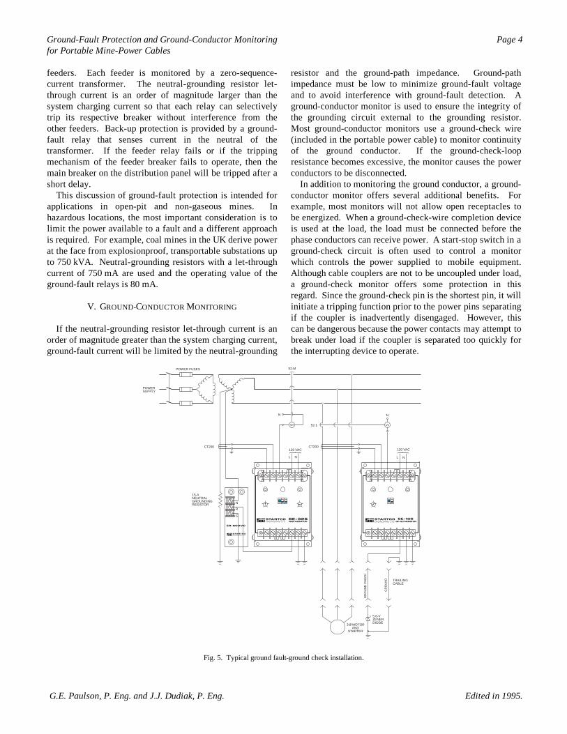
Fig. 5 shows a typical installation of a ground-fault relayand a distribution panel in a portable substation. Only onefeeder breaker is shown but it applies to panels with multiple
Littelfuse Startco
4 egaPgnirotinoM rotcudnoC-dnuorG dna noitcetorP tluaF-dnuorGfor Portable Mine-Power Cables
.5991 ni detidE .gnE .P ,kaiduD .J.J dna .gnE .P ,nosluaP .E.G
feeders. Each feeder is monitored by a zero-sequence-current transformer. The neutral-grounding resistor let-through current is an order of magnitude larger than thesystem charging current so that each relay can selectivelytrip its respective breaker without interference from theother feeders. Back-up protection is provided by a ground-fault relay that senses current in the neutral of thetransformer. If the feeder relay fails or if the trippingmechanism of the feeder breaker fails to operate, then themain breaker on the distribution panel will be tripped after ashort delay.
This discussion of ground-fault protection is intended forapplications in open-pit and non-gaseous mines. Inhazardous locations, the most important consideration is tolimit the power available to a fault and a different approachis required. For example, coal mines in the UK derive powerat the face from explosionproof, transportable substations upto 750 kVA. Neutral-grounding resistors with a let-throughcurrent of 750 mA are used and the operating value of theground-fault relays is 80 mA.
V. GROUND-CONDUCTOR MONITORING
If the neutral-grounding resistor let-through current is anorder of magnitude greater than the system charging current,ground-fault current will be limited by the neutral-grounding
resistor and the ground-path impedance. Ground-pathimpedance must be low to minimize ground-fault voltageand to avoid interference with ground-fault detection. Aground-conductor monitor is used to ensure the integrity ofthe grounding circuit external to the grounding resistor.Most ground-conductor monitors use a ground-check wire(included in the portable power cable) to monitor continuityof the ground conductor. If the ground-check-loopresistance becomes excessive, the monitor causes the powerconductors to be disconnected.
In addition to monitoring the ground conductor, a ground-conductor monitor offers several additional benefits. Forexample, most monitors will not allow open receptacles tobe energized. When a ground-check-wire completion deviceis used at the load, the load must be connected before thephase conductors can receive power. A start-stop switch in aground-check circuit is often used to control a monitorwhich controls the power supplied to mobile equipment.Although cable couplers are not to be uncoupled under load,a ground-check monitor offers some protection in thisregard. Since the ground-check pin is the shortest pin, it willinitiate a tripping function prior to the power pins separatingif the coupler is inadvertently disengaged. However, thiscan be dangerous because the power contacts may attempt tobreak under load if the coupler is separated too quickly forthe interrupting device to operate.
POWER FUSES
POWERSUPPLY
CT200
N
SH 52-1
120 VAC
L N
CT200
52-M
N
UV
120 VAC
L N
15-ANEUTRALGROUNDINGRESISTOR
TRAILINGCABLE
GR
OU
ND
GR
OU
ND
CH
EC
K
5.6-VZENERDIODE3-0 MOTOR
ANDSTARTER
N
R
G
Fig. 5. Typical ground fault-ground check installation.
egaPgnirotinoM rotcudnoC-dnuorG dna noitcetorP tluaF-dnuorG 5for Portable Mine-Power Cables
.5991 ni detidE .gnE .P ,kaiduD .J.J dna .gnE .P ,nosluaP .E.G
VI. PREFERRED GROUND-CONDUCTOR MONITORCHARACTERISTICS
A ground-conductor monitor should have the followingcharacteristics: — The open-circuit ground-check voltage should be low.
CSA Standard M421 allows 100 V. In wet locations100 V can present a hazard to personnel. It issomewhat inconsistent for a safety device to be ahazard itself.
— The monitor should use an end-of-line device so thatground-check-to-ground shorts can be detected.MSHA (USA) investigations indicate that cablesplicers have a tendency to connect the ground-checkconductor to the ground conductor when splicing acable [5].
— The monitor should have a high tolerance to induced acin the ground-check loop. Since ground check andground conductors run parallel to high-current phaseconductors, induced ac is often present. MSHAapproval requires monitors to tolerate 50 V induced orbe marked to indicate this limitation [6].
— Ground-check circuits should be failsafe. MSHAdefines a circuit to be failsafe if the failure of any onecircuit component (in all possible failure modes)initiates a tripping function, or allows the circuit tocontinue to operate properly [6].
— The monitor should not tolerate a high ground-checkloop resistance. In fact, a good design should considerboth the ground resistance and the operating value ofthe ground-fault relays so that ground-fault voltageswill be less than 100 V.
— The monitor should operate over a wide temperaturerange.
— The monitor should operate over a wide supply-voltagerange and tolerate large voltage dips (voltage can dip50% on long cables).
— The output relay should be capable of switchingcurrents of only a few mA. This is important when themonitor is used to energize an undervoltage releasecoil which may draw 20 mA or less. Bifurcatedcontact relays are designed to switch currents in the 1-mA to 2-A range.
VII. GROUND-CONDUCTOR MONITOR LIMITATIONS
The following limitations can be encountered with someground-conductor monitors. — Some ground-conductor monitors use line-frequency
signals. Circuits of this type often cannot discriminatebetween changes in loop impedance and induction inthe ground-check loop.
— Some impedance-type monitors use a step-downtransformer to detect an increase in the impedance of a
ground-check loop. The secondary winding isconnected in series with the ground-check wire and anincrease in loop impedance is observed as a decrease intransformer current. This method works very well on ade-energized cable with no induced voltage in theground-check loop; however, a small induced voltageopposing the secondary drive voltage will cause asimilar decrease in transformer current and trip themonitor. To prevent this nuisance tripping, monitorsof this type must have a phase-reversal switch so thatinduced voltage can be added to the secondary drivevoltage. The problem with this is that loop impedancecan now increase well above the trip level withoutdetection. For example, a monitor with a 32-V/3.2-Vtransformer and a 4-ohm loop will allow loopimpedance to increase by 4 ohms for each 3.2 V ofinduced voltage.
— Some ground-conductor monitors use a rectifier diodefor a completion device. Voltages induced in theground-check loop are ac but the diode only allowscurrent to flow in one direction. Consequently,completion diodes are susceptible to damage fromswitching transients unless they are protected in thereverse direction by a suppressor. These units can beaffected by induced ac which can cause nuisancetripping. Reducing this sensitivity is oftenaccomplished at the expense of the ability to detectincreases in ground-check loop impedance.
— Some ground-conductor monitors use high-frequencysignals. These circuits are often limited to short cablelengths by the line-to-ground capacitance of trailingcables.
VIII. SUMMARY
— To prevent transient overvoltage damage, thelet-through current of the grounding resistor should beequal to or greater than the system charging current.
— To achieve selective detection of a faulted feeder in aresistance-grounded distribution system, the operating(or trip) current of the ground-fault relays should belarger than the system charging current.
— For reliable tripping on all types of faults, thegrounding resistor let-through current should be atleast 7 times the operating current of the ground-faultrelays.
— A ground-fault detection system will operate only ifthe grounding conductor is continuous; therefore, asystem is required to ensure ground-conductorcontinuity.
— The resistance that the ground-check circuit willtolerate should be selected so that the product of theoperating value of the ground-fault relays and theallowable ground resistance is less than 100 V.
egaPgnirotinoM rotcudnoC-dnuorG dna noitcetorP tluaF-dnuorG 6for Portable Mine-Power Cables
.5991 ni detidE .gnE .P ,kaiduD .J.J dna .gnE .P ,nosluaP .E.G
REFERENCES
[1] C.A.A. MacPhee, "Ground fault protection for ungrounded distributionsystems". Conference record of I.A.S 1975 annual meeting, Atlanta,GA: pp. 630—637, Oct. 1975.
[2] Arthur Freund,. "Ground-fault protection for ungrounded distributionsystems". Electrical construction and maintenance. 1979.
[3] Baldwin Bridger, Jr., "High resistance grounding". Conference recordof the Industry applications society IEEE-IAS 1981 annual meeting,Philadelphia, PA: Oct. 18—24, 1981.
[4] J. Stoddard, "Sensitive earth fault protection in mines". ConferenceRecord of the IEE on electrical safety in hazardous environments,London: pp. 166—171, March 1971.
[5] Arlie B. Massey, "An introduction to ground monitoring". Conferencerecord of the Western mining industry electrotechnical conference, Reno,NV: pp. 61—82, Sept 1981.
[6] MSHA, "Approval and certification procedures for ground checkcurrents". Mine Safety and Health Administration, P.O. Box 1166,Building F. Berkley, WA 25801. 1982.
Copyright © 1995 by Startco Engineering Ltd. Presented at the MechanicalElectrical Symposium in Victoria, BC, Canada, February 19—22, 1985, andthe Canadian Institute of Mining 9th Maintenance/Engineering OperatorsConference in Val d’Or, PQ, March 3—6, 1996. Edited in 1995.
Printed in Canada.