Embed Size (px)
Citation preview

kwc ARCHITECTS inc. 201‐383 Parkdale Avenue, Ottawa, Ontario K1Y 4R4 | (613) 238‐2117 | (613) 238‐6595 fax | www.kwc‐arch.com
Tender Submission
Specifications
Ground Floor – Federal Building
C1/C2 Interior Renovations (2016)130 South Syndicate Avenue, Thunder Bay, Ontario
PWGSC no. R.079363.042
22 September 2016
1548
PWGSC Ontario SPECIFICATION Section 00 00 00 Region Project TITLE SHEET Page 1 Number R.079363.042 2016-09-27 Project Title C1/C2 INTERIOR RENOVATIONS (2016)
GROUND FLOOR – FEDERAL BUILDING 130 SOUTH SYNDICATE AVENUE, THUNDER BAY, ONTARIO
Project Number R.079363.042 Project Date 2016-09-27
END OF SECTION

2016-09-22

PWGSC Ontario LIST OF CONTENTS Section 00 01 11 Region Project Page 1 Number R.079363.042 2016-09-22 SPECIFICATIONS Section Title Pages Division 00 - Procurement and Contracting Requirements
00 00 00 SPECIFICATION TITLE SHEET 1 00 01 07 SEALS PAGE 1 Division 01 - General Requirements
01 11 00 SUMMARY OF WORK 4 01 14 00 WORK RESTRICTIONS 3 01 14 25 DESIGNATED SUBSTANCE REPORT 1 01 29 83 PAYMENT PROCEDURES FOR TESTING LABORATORY SERVICES 2 01 31 19 PROJECT MEETINGS 3 01 32 16 CONSTRUCTION PROGRESS SCHEDULE – BAR (GANTT) CHART 4 01 33 00 SUBMITTAL PROCEDURES 6 01 35 29 HEALTH AND SAFETY REQUIREMENTS 7 01 35 35 FIRE SAFETY REQUIREMENTS 5 01 41 00 REGULATORY REQUIREMENTS 2 01 42 13 ABBREVIATIONS AND ACRONYMS 11 01 45 00 QUALITY CONTROL 4 01 51 00 TEMPORARY UTILITIES 3 01 52 00 CONSTRUCTION FACILITIES 3 01 56 00 TEMPORARY BARRIERS AND ENCLOSURES 2 01 61 00 COMMON PRODUCT REQUIREMENTS 6 01 73 00 EXECUTION 3 01 74 11 CLEANING 3 01 74 20 CONSTRUCTION/DEMOLITION WASTE MANAGEMENT AND DISPOSAL 2 01 77 00 CLOSEOUT PROCEDURES 2 01 78 00 CLOSEOUT SUBMITTALS 8 01 79 00 DEMONSTRATION AND TRAINING 3 Division 02 - Existing Conditions
02 41 99 DEMOLITION 3 02 81 01 HAZARDOUS MATERIALS 5 Division 06 - Wood, Plastics, and Composites
06 40 01 ARCHITECTURAL WOODWORK 6 Division 07 - Thermal and Moisture Protection
07 52 00 MODIFIED BITUMINOUS MEMBRANE ROOFING 8 07 84 00 FIRESTOPPING 6 07 90 00 JOINT SEALING 4 Division 08 - Openings

PWGSC Ontario LIST OF CONTENTS Section 00 01 11 Region Project Page 2 Number R.079363.042 2016-09-22 08 11 13 STEEL HOLLOW METAL DOORS, FRAMES AND SCREENS 4 08 14 11 WOOD DOORS 3 08 31 13 ACCESS DOORS AND FRAMES 3 08 34 65 ACOUSTIC WOOD DOORS AND STEEL FRAMES ASSEMBLIES 5 08 71 11 FINISH HARDWARE 12 08 71 12 LOW ENERGY POWER DOOR OPERATOR 4 08 80 00 GLAZING 2 08 87 54 GLAZING FILMS 5 Division 09 - Finishes
09 21 99 PARTITIONS 6 09 30 14 TILING 7 09 51 23 ACOUSTIC TILE CEILINGS 2 09 65 00 RESILIENT FLOORING 6 09 68 01 CARPET TILE 7 09 91 99 PAINTING 7 Division 10 - Specialties
10 14 00 SIGNAGE 2 10 28 00 MANUFACTURED SPECIALTIES 3 Division 21 - Fire Suppression
21 05 01 COMMON WORK RESULTS FOR MECHANICAL 5 21 12 01 STANDPIPE AND HOSE ASSEMBLY 3 Division 22 – Plumbing
22 11 16 DOMESTIC WATER PIPING 3 22 13 18 DRAINAGE WASTE AND VENT PIPING – PLASTIC 3 22 42 01 PLUMBING SPECIALTIES AND ACCESSORIES 3 22 42 03 COMMERCIAL WASHROOM FIXTURES 3 22 42 16 COMMERCIAL LAVATORIES AND SINKS 3 Division 23 - Heating, Ventilating and Air-Conditioning (HVAC)
23 05 05 INSTALLATION OF PIPEWORK 5 23 05 23.01 VALVES – BRONZE 2 23 05 29 HANGERS AND SUPPORTS FOR HVAC PIPING AND EQUIPMENT 7 23 05 53.01 MECHANICAL IDENTIFICATION 5 23 07 13 DUCT INSULATION 5 23 07 15 THERMAL INSULATION FOR PIPING 5 23 09 43 PNEUMATIC CONTROL SYSTEM FOR HVAC 1 23 31 13.01 METAL DUCTS - LOW PRESSURE TO 500 PA 5 23 33 00 AIR DUCT ACCESSORIES 2 23 33 14 DAMPERS – BALANCING 2 23 33 16 DAMPERS – FIRE 2 23 33 46 FLEXIBLE DUCTS 2 23 33 53 DUCT LINERS 3

PWGSC Ontario LIST OF CONTENTS Section 00 01 11 Region Project Page 3 Number R.079363.042 2016-09-22 23 34 00 HVAC FANS 2 23 36 00 AIR TERMINAL UNITS 2 23 37 13 DIFFUSERS, REGISTERS AND GRILLES 2 23 81 23 DX SPLIT SYSTEM 4 Division 26 - Electrical
26 05 00 COMMON WORK RESULTS FOR ELECTRICAL 8 26 05 21 WIRES AND CABLES (0-1000 V) 2 26 05 28 GROUNDING – SECONDARY 4 26 05 29 HANGERS AND SUPPORTS FOR ELECTRICAL SYSTEMS 2 26 05 32 OUTLET BOXES, CONDUIT BOXES AND FITTINGS 2 26 05 34 CONDUITS, CONDUIT FASTENINGS AND CONDUIT FITTINGS 4 26 05 36 CABLE TRAYS FOR ELECTRICAL SYSTEMS 2 26 27 26 WIRING DEVICES 4 26 27 73 DOOR CHIMES 2 26 28 16.02 MOULDED CASE CIRCUIT BREAKERS 3 26 28 23 DISCONNECT SWITCHES - FUSED AND NON-FUSED 2 26 29 10 MOTOR STARTERS TO 600 V 4 26 50 00 LIGHTING 3 26 50 01 MANUFACTURED WIREING SYSTEMS 2 26 51 19 SOUND MASKING SYSTEMS 8 26 53 00 EXIT LIGHTS 2 Division 26 - Communications
27 41 00 AUDIO-VIDEO COMMUNICATIONS 2 Division 28 - Electronic Safety and Security
28 08 01 COMMISSIONING FIRE ALARM SYSTEMS 3 28 13 27 SECURITY DOOR SUPERVISION 5 28 16 00 INTRUSION DETECTION 5 28 23 00 VIDEO SURVEILLANCE 5 28 31 00.01 MULTIPLEX FIRE ALARM SYSTEM 8 LIST OF DRAWINGS Architectural
A0 COVER SHEET, LIST OF DRAWINGS, OBC AND NBC MATRIX A0.1 LEGENDS AND SCHEDULES A0.2 GROUND FLOOR AREAS OF OWNER OCCUPANCY DURING CONSTRUCTION A1 GROUND FLOOR DEMOLITION PLAN A2 GROUND FLOOR PLAN NEW CONSTRUCTION A3 GROUND FLOOR REFLECTED CEILING PLAN DEMOLITION A4 GROUND FLOOR REFLECTED CEILING PLAN NEW CONSTRUCTION A4.1 BASEMENT REFLECTED CEILING PALN, PARTIAL ROOF PLAN, AND ROOF DETAILS A5 DETAIL PLANS, INTERIOR ELEVATIONS, SECTIONS AND DETAILS A6 DETAIL PLANS, INTERIOR ELEVATIONS, SECTIONS AND DETAILS A7 DETAIL PLANS, INTERIOR ELEVATIONS, SECTIONS AND DETAILS A8 DETAIL PLANS, INTERIOR ELEVATIONS, SECTIONS AND DETAILS A9 DETAIL PLANS, INTERIOR ELEVATIONS, SECTIONS AND DETAILS
PWGSC Ontario LIST OF CONTENTS Section 00 01 11 Region Project Page 4 Number R.079363.042 2016-09-22 A10 DETAIL PLANS, INTERIOR ELEVATIONS, SECTIONS AND DETAILS A11 PARTITIONS PLAN DETAILS, PARTITIONS SECTIONS AND FRAMING DIAGRAMS A12 GROUND FLOOR PLAN, FURNITURE LAYOUT FOR COORDINATION ONLY Mechanical
M1 MECHANICAL DRAWING LIST, LEGENDS, SCHEDULES & DETAILS M2 MECHANICAL FIRE PROTECTION, PLUMBING & UTILITIES DEMOLITION & NEW WORK M3 MECHANICAL HVAC DEMOLITION & NEW WORK Electrical E1 ELECTRICAL TITLE SHEET E2 ELECTRICAL LIGHTING AND FIRE ALARM E3 ELECTRICAL POWER AND SYSTEMS
Security T100 SECURITY AND AUDIO VISUAL PLANS AND DETAILS END OF SECTION
PWGSC Ontario SUMMARY OF WORK Section 01 11 00 Region Project Page 1 Number R.079363.042 2016-09-22
PART 1 - GENERAL 1.1 SECTION INCLUDES
.1 Title and description of Work. .2 Contract Method.
.3 Work by others.
.4 Future work.
.5 Work sequence.
.6 Contractor use of premises.
.7 Owner occupancy.
.8 Partial Owner occupancy.
.9 Alterations to existing building.
1.2 PRECEDENCE
.1 Division 01 Sections take precedence over technical specification
sections in other Divisions of this Project Manual. 1.3 WORK COVERED BY CONTRACT DOCUMENTS
.1 Work of this Contract comprises of interior fit-up and renovation,
mainly on the ground floor of a 3 storey Federal Building, located at 130 South Syndicate Avenue, Thunder Bay Ontario.
.2 The work includes, but not limited to, selective demolitions and fit-up
of new spaces for Client 1 (C1), Client 2 (C2), Canadian Revenue Agency (CRA) and to base building (BB)spaces.
1.4 CONTRACT METHOD
PWGSC Ontario SUMMARY OF WORK Section 01 11 00 Region Project Page 2 Number R.079363.042 2016-09-22
.1 Construct work under lump sum contract.
.2 Relations and responsibilities between Contractor and subcontractors and suppliers and subcontractors assigned by Departmental Representative are as defined in Conditions of Contract. Assigned Subcontractors must, in addition: .1 Furnish to Contractor, bonds covering faithful performance of subcontracted work and payment of obligations thereunder when Contractor is required to furnish such bonds to Departmental Representative. .2 Purchase and maintain liability insurance to protect Contractor from claims for not less than limits of liability which Contractor is required to provide to Departmental Representative.
1.5 COST BREAKDOWN
.1 Within 48 hours of notification of acceptance of bid furnish a cost breakdown by Section aggregating contract price.
.2 Show separately cost of equipment purchased exempt from Ontario Retail
Sales Tax under your Ontario Sales Tax licence number.
.3 Within 48 hours of acceptance of bid submit a list of subcontractors. 1.6 WORK BY OTHERS
.1 Work of Project executed during Work of this Contract, and which is
specifically excluded from this Contract:
.1 IT/Communications work that is not shown in the contract documents.
.2 Supply and installation of furniture in C1 and C2 spaces. .3 Work by Chuub Edwards as related to CRA spaces.
.2 The Contractor shall for the purpose of the Ontario Occupational Health
and Safety Act and Regulations for Construction Projects, and for the duration of the Work of the Contract: .1 Assume the role of Constructor in accordance with the Authority Having Jurisdictions. .2 Agree, in the event of two or more Contractors working at the same time and space at the work site, without limiting the General Conditions GC3.7, to the Departmental Representative's order to:
.1 Assume, as the Constructor, the responsibility for the Departmental Representative's other Contractors.
PWGSC Ontario SUMMARY OF WORK Section 01 11 00 Region Project Page 3 Number R.079363.042 2016-09-22 1.7 WORK SEQUENCE
.1 Construct Work in stages to accommodate Departmental Representative's
continued use of premises during construction.
.2 Coordinate Progress Schedule and coordinate with Departmental Representative Occupancy during construction.
.3 Required stages:
.1 Refer to Section 01 32 16 - Construction Progress Schedule.
.4 Construct Work in stages to provide for continuous public usage. Do not close off public usage of facilities until use of one stage of Work will provide alternate usage.
.6 Maintain fire access/control.
1.8 CONTRACTOR USE OF PREMISES
.1 Contractor shall limit use of premises for Work, for storage, and for access, to allow; .1 Owner occupancy on the 2nd, 3rd and basement floor levels. .2 Partial owner occupancy on the ground floor, as indicated on the
architectural drawings. .3 Work by other contractors. .4 Public usage.
.2 Coordinate use of premises under direction of Departmental
Representative.
.3 Obtain and pay for use of additional storage or work areas needed for operations under this Contract.
1.9 OWNER OCCUPANCY
.1 Owner will occupy premises during entire construction period for
execution of normal operations. .1 Owner occupancy on the 2nd, 3rd and basement floor levels. .2 Partial owner occupancy on the ground floor, as indicated on the
architectural drawings.
.2 Cooperate with Departmental Representative in scheduling operations to minimize conflict and to facilitate Departmental Representative usage.

PWGSC Ontario SUMMARY OF WORK Section 01 11 00 Region Project Page 4 Number R.079363.042 2016-09-22 1.10 ALTERATIONS TO EXISTING BUILDING
.1 Provide new openings required in existing construction.
.2 Block in openings where items removed with material and finish to match
existing adjoining construction.
.3 Undercut existing doors to clear new carpet.
PART 2 - PRODUCTS 2.1 NOT USED
.1 Not used.
PART 3 - EXECUTION 3.1 NOT USED
.1 Not used.
END OF SECTION

PWGSC Ontario WORK RESTRICTIONS Section 01 14 00 Region Project Page 1 Number R.079363.042 2016-09-22
PART 1 - GENERAL 1.1 ACCESS AND EGRESS
.1 Design, construct and maintain temporary "access to" and "egress from" work areas, including stairs, runways, ramps or ladders, independent of finished surfaces and in accordance with relevant municipal, provincial and other regulations.
1.2 USE OF SITE AND FACILITIES
.1 Execute work with least possible interference or disturbance to normal use of premises. Make arrangements with Departmental Representative to facilitate work as stated.
.2 Maintain existing services to building and provide for personnel and
vehicle access.
.3 Where security is reduced by work provide temporary means to maintain security.
.4 Departmental Representative will assign sanitary facilities for use by
Contractor's personnel. Keep facilities clean.
.5 Use only designated freight elevators, existing in building for moving workers and material. .1 Protect walls of assigned elevators, to approval of Departmental Representative prior to use. .2 Accept liability for damage, safety of equipment and overloading of existing equipment.
.6 Closures: protect work temporarily until permanent enclosures are
completed. 1.3 ALTERATIONS, ADDITIONS OR REPAIRS TO EXISTING BUILDING
.1 Execute work with least possible interference or disturbance to building operations, occupants, public and normal use of premises. Arrange with Departmental Representative to facilitate execution of work.

PWGSC Ontario WORK RESTRICTIONS Section 01 14 00 Region Project Page 2 Number R.079363.042 2016-09-22
.2 Structural and non-structural cutting and coring: .1 Do not cut or core steel beams or columns, concrete beams, floor
joists or walls except with written permission of Departmental Representative.
.2 Individual cores up to 200 mm dia. may be cut through floor slabs after checking that no structural steel members will be intersected.
.3 Refer groups of cores or saw cut openings for Departmental Representative’s approval.
.4 Provide Ferroscan investigation scans at slab coring locations. 1.4 EXISTING SERVICES
.1 Notify, Departmental Representative utility companies of intended interruption of services and obtain required permission.
.2 Where Work involves breaking into or connecting to existing services,
give Departmental Representative 72 hours of notice for necessary interruption of mechanical or electrical service throughout course of work. Keep duration of interruptions minimum. Carry out interruptions after normal working hours of occupants, preferably on weekends.
.3 Provide for personnel and vehicular traffic.
.4 Construct barriers in accordance with Section 01 56 00.
1.5 SPECIAL REQUIREMENTS
.1 Paint and carpet public or Departmental Representative occupied areas Monday to Friday from 18:00 to 07:00 hours only and on Saturdays, Sundays, and statutory holidays.
.2 Carry out noise generating Work Monday to Friday from 18:00 to 07:00
hours only and on Saturdays, Sundays, and statutory holidays.
.3 Submit schedule in accordance with Section 01 32 16.07 - Construction Progress Schedule - Bar (GANTT) Chart.
.4 Ensure Contractor's personnel employed on site become familiar with and
obey regulations including safety, fire, traffic and security regulations.
.5 Keep within limits of work and avenues of ingress and egress.
.6 Ingress and egress of Contractor vehicles at site is limited to pick-up
and delivery at building loading dock.
PWGSC Ontario WORK RESTRICTIONS Section 01 14 00 Region Project Page 3 Number R.079363.042 2016-09-22
.7 Deliver materials outside of peak traffic hours 17:00 to 07:00 and 13:00
to 15:00 unless otherwise approved by Departmental Representative. .8 On-site parking for contractors is not available.
1.6 SECURITY
.1 Where security has been reduced by Work of Contract, provide temporary means to maintain security.
.2 Security clearances:
.1 Personnel employed on this project will be subject to security check. Obtain clearance, as instructed, for each individual who will require to enter premises. .2 Personnel will be checked daily at start of work shift and provided with pass which must be worn at all times. Pass must be returned at end of work shift and personnel checked out.
1.7 BUILDING SMOKING ENVIRONMENT
.1 Comply with smoking restrictions. Smoking is not permitted.
PART 2 - PRODUCTS 2.1 NOT USED
.1 Not Used.
PART 3 - EXECUTION 3.1 NOT USED
.1 Not Used.
END OF SECTION

PWGSC Ontario DESIGNATED SUBSTANCE Section 01 14 25 Region Project REPORT Page 1 Number R.079363.042 2016-09-22
Designated Substance Report is available for viewing upon request from Departmental Representative
END OF SECTION

PWGSC Ontario PAYMENT PROCEDURES FOR Section 01 29 83 Region Project TESTING LABORATORY SERVICES Page 1 Number R.079363.042 2016-09-22
PART 1 - GENERAL 1.1 RELATED REQUIREMENTS
.1 Particular requirements for inspection and testing to be carried out
by testing laboratory designated by Departmental Representative. 1.2 APPOINTMENT AND PAYMENT
.1 Departmental Representative will appoint and pay for services of testing laboratory except follows: .1 Inspection and testing required by laws, ordinances, rules, regulations or orders of public authorities. .2 Inspection and testing performed exclusively for Contractor's convenience. .3 Testing, adjustment and balancing of conveying systems, mechanical and electrical equipment and systems. .4 Mill tests and certificates of compliance. .5 Tests specified to be carried out by Contractor under supervision of Departmental Representative.
.2 Where tests or inspections by designated testing laboratory reveal Work not in accordance with contract requirements, pay costs for additional tests or inspections as required by Departmental Representative to verify acceptability of corrected work.
1.3 CONTRACTOR'S RESPONSIBILITIES
.1 Provide labour, equipment and facilities to:
.1 Provide access to Work for inspection and testing.
.2 Facilitate inspections and tests.
.3 Make good Work disturbed by inspection and test.
.4 Provide storage on site for laboratory's exclusive use to store equipment and cure test samples.
.2 Notify Departmental Representative 72 hours minimum sufficiently in
advance of operations to allow for assignment of laboratory personnel and scheduling of test.
.3 Where materials are specified to be tested, deliver representative
samples in required quantity to testing laboratory.
PWGSC Ontario PAYMENT PROCEDURES FOR Section 01 29 83 Region Project TESTING LABORATORY SERVICES Page 2 Number R.079363.042 2016-09-22
.4 Pay costs for uncovering and making good Work that is covered before required inspection or testing is completed and approved by Departmental Representative.
PART 2 - PRODUCTS 2.1 NOT USED
.1 Not Used.
PART 3 - EXECUTION 3.1 NOT USED
.1 Not Used.

PWGSC Ontario PROJECT MEETINGS Section 01 31 19 Region Project Page 1 Number R.079363.042 2016-09-22
PART 1 - GENERAL 1.1 ADMINISTRATIVE
.1 Schedule and administer project meetings throughout the progress of the work at the call of Departmental Representative.
.2 Prepare agenda for meetings.
.3 Distribute written notice of each meeting 4 days in advance of meeting
date to Departmental Representative.
.4 Provide physical space and make arrangements for meetings.
.5 Preside at meetings.
.6 Record the meeting minutes. Include significant proceedings and decisions. Identify actions by parties.
.7 Reproduce and distribute copies of minutes within three days after
meetings and transmit to Departmental Representative, meeting participants and affected parties not in attendance.
.8 Representative of Contractor, Subcontractor and suppliers attending
meetings will be qualified and authorized to act on behalf of party each represents.
1.2 PRECONSTRUCTION MEETING
.1 Within 15 days after award of Contract, request a meeting of parties in contract to discuss and resolve administrative procedures and responsibilities.
.2 Departmental Representative, Contractor, major Subcontractors, field
inspectors will be in attendance.
.3 Establish time and location of meeting and notify parties concerned minimum 5 days before meeting.
.4 Incorporate mutually agreed variations to Contract Documents into
Agreement, prior to signing.

PWGSC Ontario PROJECT MEETINGS Section 01 31 19 Region Project Page 2 Number R.079363.042 2016-09-22
.5 Agenda to include:
.1 Appointment of official representative of participants in the Work. .2 Schedule of Work: in accordance with Section 01 32 16. .3 Schedule of submission of shop drawings, samples, mock-ups, colour chips. Submit submittals in accordance with Section 01 33 00. .4 Requirements for temporary facilities, site signage, offices, utilities, dust tight screens, in accordance with Section 01 52 00. .5 Delivery schedule of specified equipment. .6 Site security in accordance with Section 01 56 00. .7 Health and safety in accordance with Section 01 35 29.06. .8 Proposed changes, change orders, procedures, approvals required, mark-up percentages permitted, time extensions, overtime, administrative requirements. .9 Owner provided products. .10 Record drawings and specifications in accordance with Sections 01 33 00 and 01 78 00. .11 Maintenance manuals in accordance with Section 01 78 00. .12 Take-over procedures, acceptance, warranties in accordance with Section 01 78 00. .13 Monthly progress claims, administrative procedures, photographs, hold backs. .14 Appointment of inspection and testing agencies or firms. .15 Insurances, transcript of policies.
1.3 PROGRESS MEETINGS
.1 During course of Work and 4 weeks prior to project completion, schedule progress meetings bi-monthly.
.2 Contractor, major Subcontractors involved in Work and Departmental
Representative are to be in attendance.
.3 Notify parties minimum 5 days prior to meetings.
.4 Record minutes of meetings and circulate to attending parties and affected parties not in attendance within 3 days after meeting.
.5 Agenda to include the following:
.1 Review, approval of minutes of previous meeting.
.2 Review of Work progress since previous meeting.
.3 Field observations, problems, conflicts.
.4 Problems which impede construction schedule.
.5 Review of off-site fabrication delivery schedules.
.6 Corrective measures and procedures to regain projected schedule.
.7 Revision to construction schedule.

PWGSC Ontario PROJECT MEETINGS Section 01 31 19 Region Project Page 3 Number R.079363.042 2016-09-22
.8 Progress schedule, during succeeding work period.
.9 Review submittal schedules: expedite as required.
.10 Maintenance of quality standards.
.11 Review proposed changes for affect on construction schedule and on completion date. .12 Other business.
PART 2 - PRODUCTS 2.1 NOT USED
.1 Not Used.
PART 3 - EXECUTION 3.1 NOT USED
.1 Not Used.
END OF SECTION

PWGSC Ontario CONSTRUCTION PROGRESS Section 01 32 16 Region Project SCHEDULE - BAR (GANTT) Page 1 Number R.079363.042 CHART 2016-09-22
PART 1 - GENERAL 1.1 DEFINITIONS
.1 Activity: element of Work performed during course of Project. Activity
normally has expected duration, and expected cost and expected resource requirements. Activities can be subdivided into tasks.
.2 Bar Chart (GANTT Chart): graphic display of schedule-related
information. In typical bar chart, activities or other Project elements are listed down left side of chart, dates are shown across top, and activity durations are shown as date-placed horizontal bars. Generally Bar Chart should be derived from commercially available computerized project management system.
.3 Baseline: original approved plan (for project, work package, or
activity), plus or minus approved scope changes.
.4 Construction Work Week: Monday to Friday, inclusive, will provide five day work week and define schedule calendar working days as part of Bar (GANTT) Chart submission.
.5 Duration: number of work periods (not including holidays or other
nonworking periods) required to complete activity or other project element. Usually expressed as workdays or workweeks.
.6 Master Plan: summary-level schedule that identifies major activities
and key milestones.
.7 Milestone: significant event in project, usually completion of major deliverable.
.8 Project Schedule: planned dates for performing activities and the
planned dates for meeting milestones. Dynamic, detailed record of tasks or activities that must be accomplished to satisfy Project objectives. Monitoring and control process involves using Project Schedule in executing and controlling activities and is used as basis for decision making throughout project life cycle.
.9 Project Planning, Monitoring and Control System: overall system
operated by Departmental Representative to enable monitoring of project work in relation to established milestones.
PWGSC Ontario CONSTRUCTION PROGRESS Section 01 32 16 Region Project SCHEDULE - BAR (GANTT) Page 2 Number R.079363.042 CHART 2016-09-22
1.2 REQUIREMENTS
.1 Ensure Master Plan and Detail Schedules are practical and remain within
specified Contract duration.
.2 Plan to complete Work in accordance with prescribed milestones and time frame.
.3 Limit activity durations to maximum of approximately 10 working days,
to allow for progress reporting.
.4 Ensure that it is understood that Award of Contract or time of beginning, rate of progress, Certificate of Substantial Performance and Certificate of Completion as defined times of completion are of essence of this contract.
1.3 SUBMITTALS
.1 Provide submittals in accordance with Section 01 33 00.
.2 Submit to Departmental Representative within 10 working days of Award of Contract Bar (GANTT) Chart as Master Plan for planning, monitoring and reporting of project progress.
.3 Submit Project Schedule to Departmental Representative within 5 working
days of receipt of acceptance of Master Plan. 1.4 PROJECT MILESTONES
.1 Project milestones form interim targets for Project Schedule. .2 Refer to 1.6 PROJECT SCHEDULE for project milestone dates.
1.5 MASTER PLAN
.1 Structure schedule to allow orderly planning, organizing and execution of Work as Bar Chart (GANTT).
.2 Departmental Representative will review and return revised schedules
within 5 working days.
.3 Revise impractical schedule and resubmit within 5 working days.
.4 Accepted revised schedule will become Master Plan and be used as
PWGSC Ontario CONSTRUCTION PROGRESS Section 01 32 16 Region Project SCHEDULE - BAR (GANTT) Page 3 Number R.079363.042 CHART 2016-09-22
baseline for updates. 1.6 PROJECT SCHEDULE
.1 Develop detailed Project Schedule derived from Master Plan.
.2 Project Schedule preset milestones to include the following dates: 1. January 10, 2017 Certificate of Substantial Performance for:
a. All C2 spaces and demising walls between C2 spaces and Base Building Corridors.
b. All demising walls between C1 spaces and Base Building Corridor 100.2.
c. Base Building Washrooms 100.3 and 100.4. d. All CRA spaces including demising wall between Base Building
Corridor 110.1 and all other CRA spaces. 2. January 16, 2017 In Service Date (job is complete and spaces is fully
functional and occupied)of: a. All C2 spaces and demising walls with Base Building Corridors. b. Base Building Washrooms 100.3 and 100.4. c. All CRA spaces including demising wall between Base Building
Corridor 110.1 and all other CRA spaces. 3. March 13, 2017 or earlier Certificate of Substantial Performance
for: a. All C1 spaces.
4. March 31, 2017 or earlier In Service Date (job is complete and spaces is fully functional and occupied)of:
a. All C1 spaces.
.3 Ensure detailed Project Schedule includes as minimum milestone and activity types as follows:
.1 Award. .2 Shop Drawings, Samples. .3 Permits. .4 Mobilization. .5 Interior Removals and Selective Demolition .6 Interior partition framing. .7 Drywall boarding. .8 Doors and frames. .9 Suspended ceilings. .10 Interior finishes. .11 Plumbing. .12 Lighting. .13 Electrical. .14 Piping. .15 Controls. .16 Heating, Ventilating, and Air Conditioning. .17 Millwork. .18 Fire Systems. .19 Testing and Commissioning.

PWGSC Ontario CONSTRUCTION PROGRESS Section 01 32 16 Region Project SCHEDULE - BAR (GANTT) Page 4 Number R.079363.042 CHART 2016-09-22
.20 Supplied equipment long delivery items.
.21 Departmental Representative supplied equipment required dates. 1.7 PROJECT SCHEDULE REPORTING
.1 Update Project Schedule on bi-weekly basis reflecting activity changes and completions, as well as activities in progress.
.2 Include as part of Project Schedule, narrative report identifying Work
status to date, comparing current progress to baseline, presenting current forecasts, defining problem areas, anticipated delays and impact with possible mitigation.
1.8 PROJECT MEETINGS
.1 Discuss Project Schedule at regular site meetings specified in Section 01 31 19, identify activities that are behind schedule and provide measures to regain slippage. Activities considered behind schedule are those with projected start or completion dates later than current approved dates shown on baseline schedule.
.2 Weather related delays with their remedial measures will be discussed
and negotiated.
PART 2 - PRODUCTS 2.1 NOT USED
.1 Not used.
PART 3 - EXECUTION 3.1 NOT USED
.1 Not used.
END OF SECTION

PWGSC Ontario SUBMITTAL PROCEDURES Section 01 33 00 Region Project Page 1 Number R.079363.042 2016-09-22
PART 1 - GENERAL 1.1 ADMINISTRATIVE
.1 Submit to Departmental Representative submittals listed for review. Submit promptly and in orderly sequence to not cause delay in Work. Failure to submit in ample time is not considered sufficient reason for extension of Contract Time and no claim for extension by reason of such default will be allowed.
.2 Do not proceed with Work affected by submittal until review is complete.
.3 Present shop drawings, product data, samples and mock-ups in SI Metric
units.
.4 Where items or information is not produced in SI Metric units converted values are acceptable.
.5 Review submittals prior to submission to Departmental Representative.
This review represents that necessary requirements have been determined and verified, or will be, and that each submittal has been checked and co-ordinated with requirements of Work and Contract Documents. Submittals not stamped, signed, dated and identified as to specific project will be returned without being examined and considered rejected.
.6 Notify Departmental Representative, in writing at time of submission,
identifying deviations from requirements of Contract Documents stating reasons for deviations.
.7 Verify field measurements and affected adjacent Work are co-ordinated.
.8 Contractor's responsibility for errors and omissions in submission is
not relieved by Departmental Representative's review of submittals.
.9 Contractor's responsibility for deviations in submission from requirements of Contract Documents is not relieved by Departmental Representative review.
.10 Keep one reviewed copy of each submission on site.
.11 Submit number of hard copies specified for each type and format of
submittal and also submit in electronic format as pdf files. Forward pdf, NMSEdit Professional spp, MS Word, MS Excel, [MS Project] and Autocad dwg files on USB compatible with PWGSC encryption requirements or through email or alternate electronic file sharing service such as

PWGSC Ontario SUBMITTAL PROCEDURES Section 01 33 00 Region Project Page 2 Number R.079363.042 2016-09-22
ftp, as directed by Departmental Representative. 1.2 SHOP DRAWINGS AND PRODUCT DATA
.1 The term "shop drawings" means drawings, diagrams, illustrations, schedules, performance charts, brochures and other data which are to be provided by Contractor to illustrate details of a portion of Work.
.2 Submit drawings stamped and signed by professional engineer registered
or licensed in Province of Ontario of Canada.
.3 Indicate materials, methods of construction and attachment or anchorage, erection diagrams, connections, explanatory notes and other information necessary for completion of Work. Where articles or equipment attach or connect to other articles or equipment, indicate that such items have been co-ordinated, regardless of Section under which adjacent items will be supplied and installed. Indicate cross references to design drawings and specifications.
.4 Allow 7 working days for Departmental Representative's review of each
submission.
.5 Adjustments made on shop drawings by Departmental Representative are not intended to change Contract Price. If adjustments affect value of Work, state such in writing to Departmental Representative prior to proceeding with Work.
.6 Make changes in shop drawings as Departmental Representative may
require, consistent with Contract Documents. When resubmitting, notify Departmental Representative in writing of revisions other than those requested.
.7 Accompany submissions with transmittal letter, in duplicate,
containing: .1 Date. .2 Project title and number. .3 Contractor's name and address. .4 Identification and quantity of each shop drawing, product data and sample. .5 Other pertinent data.
.8 Submissions shall include:
.1 Date and revision dates.
.2 Project title and number.
.3 Name and address of: .1 Subcontractor. .2 Supplier. .3 Manufacturer.
.4 Contractor's stamp, signed by Contractor's authorized
PWGSC Ontario SUBMITTAL PROCEDURES Section 01 33 00 Region Project Page 3 Number R.079363.042 2016-09-22
representative certifying approval of submissions, verification of field measurements and compliance with Contract Documents. .5 Details of appropriate portions of Work as applicable:
.1 Fabrication.
.2 Layout, showing dimensions, including identified field dimensions, and clearances. .3 Setting or erection details. .4 Capacities. .5 Performance characteristics. .6 Standards. .7 Operating weight. .8 Wiring diagrams. .9 Single line and schematic diagrams. .10 Relationship to adjacent work.
.9 After Departmental Representative's review, distribute copies.
.10 Submit three hard copies and one electronic copy of shop drawings for
each requirement requested in specification Sections and as Departmental Representative may reasonably request.
.11 Submit three hard copies and one electronic copy of product data sheets
or brochures for requirements requested in specification Sections and as requested by Departmental Representative where shop drawings will not be prepared due to standardized manufacture of product.
.12 Submit three hard copies and one electronic copy of test reports for
requirements requested in specification Sections and as requested by Departmental Representative. .1 Report signed by authorized official of testing laboratory that material, product or system identical to material, product or system to be provided has been tested in accord with specified requirements. .2 Testing must have been within 3 years of date of contract award for project.
.13 Submit three hard copies and one electronic copy of certificates for
requirements requested in specification Sections and as requested by Departmental Representative. .1 Statements printed on manufacturer's letterhead and signed by responsible officials of manufacturer of product, system or material attesting that product, system or material meets specification requirements. .2 Certificates must be dated after award of project contract complete with project name.
.14 Submit three hard copies and one electronic copy of manufacturer’s
instructions for requirements requested in specification Sections and as requested by Departmental Representative. .1 Pre-printed material describing installation of product, system or material, including special notices and Material Safety Data Sheets

PWGSC Ontario SUBMITTAL PROCEDURES Section 01 33 00 Region Project Page 4 Number R.079363.042 2016-09-22
concerning impedances, hazards and safety precautions.
.15 Submit three hard copies and one electronic copy of Manufacturer's Field Reports for requirements requested in specification Sections and as requested by Departmental Representative.
.16 Documentation of the testing and verification actions taken by
manufacturer's representative to confirm compliance with manufacturer's standards or instructions.
.17 Submit three hard copies and one electronic copy of Operation and
Maintenance Data for requirements requested in specification Sections and as requested by Departmental Representative.
.18 Delete information not applicable to project.
.19 Supplement standard information to provide details applicable to
project.
.20 If upon review by Departmental Representative, no errors or omissions are discovered or if only minor corrections are made, copies will be returned and fabrication and installation of Work may proceed. If shop drawings are rejected, noted copy will be returned and resubmission of corrected shop drawings, through same procedure indicated above, must be performed before fabrication and installation of Work may proceed.
.21 The review of shop drawings by Public Works and Government Services
Canada (PWGSC) is for sole purpose of ascertaining conformance with general concept. .1 This review shall not mean that PWGSC approves detail design inherent in shop drawings, responsibility for which shall remain with Contractor submitting same, and such review shall not relieve Contractor of responsibility for errors or omissions in shop drawings or of responsibility for meeting requirements of construction and Contract Documents. .2 Without restricting generality of foregoing, Contractor is responsible for dimensions to be confirmed and correlated at job site, for information that pertains solely to fabrication processes or to techniques of construction and installation and for co-ordination of Work of sub-trades.
1.3 SAMPLES
.1 Submit for review samples in duplicate as requested in respective specification Sections. Label samples with origin and intended use.
.2 Deliver samples prepaid to Departmental Representative's business
address.

PWGSC Ontario SUBMITTAL PROCEDURES Section 01 33 00 Region Project Page 5 Number R.079363.042 2016-09-22
.3 Notify Departmental Representative in writing, at time of submission of deviations in samples from requirements of Contract Documents.
.4 Where colour, pattern or texture is criterion, submit full range of
samples.
.5 Adjustments made on samples by Departmental Representative are not intended to change Contract Price. If adjustments affect value of Work, state such in writing to Departmental Representative prior to proceeding with Work.
.6 Make changes in samples which Departmental Representative may require,
consistent with Contract Documents.
.7 Reviewed and accepted samples will become standard of workmanship and material against which installed Work will be verified.
1.4 MOCK-UPS
.1 Erect mock-ups in accordance with Section 01 45 00.
1.5 PHOTOGRAPHIC DOCUMENTATION
.1 Submit electronic copy of colour digital photography in jpg format, standard resolution monthly with progress statement.
.2 Project identification: name and number of project and date of exposure
indicated.
.3 Number of viewpoints: 50 locations. .1 Viewpoints and their location as determined by Departmental Representative.
.4 Frequency of photographic documentation: monthly.
.1 Upon completion of: framing and services before concealment, of Work, and as directed by Departmental Representative.
1.6 FEES, PERMITS AND CERTIFICATES
.1 Pay all fees and obtain all permits. Provide authorities with plans and information for acceptance certificates. Provide inspection certificates as evidence that work conforms to requirements of Authority having jurisdiction.
.2 Provide authorities having jurisdiction with information requested.

PWGSC Ontario SUBMITTAL PROCEDURES Section 01 33 00 Region Project Page 6 Number R.079363.042 2016-09-22
.3 Submit acceptable certificate stating that suspended ceiling systems provide adequate support for electrical fixtures, as required by current bulletin of Electrical Safety Authority (ESA).
PART 2 - PRODUCTS 2.1 NOT USED
.1 Not Used.
PART 3 - EXECUTION 3.1 NOT USED
.1 Not Used.
END OF SECTION
PWGSC Ontario HEALTH AND SAFETY Section 01 35 29 Region Project REQUIREMENTS Page 1 Number R.079363.042 2016-09-22
PART 1 - GENERAL 1.1 REFERENCES
.1 Canadian Standards Association (CSA): Canada .1 CSA S350-M1980(R2003), Code of Practice for Safety in Demolition of Structures.
.2 National Building Code 2015 (NBC):
.1 NBC 2015, Division B, Part 8 Safety Measures at Construction and Demolition Sites.
.3 National Fire Code 2015 (NFC):
.1 NFC 2015, Division B, Part 5 Hazardous Processes and Operations, subsection 5.6.1.3 Fire Safety Plan.
.4 Province of Ontario:
.1 Occupational Health and Safety Act Revised Statutes of Ontario 1990, Chapter O.1 as amended, and Regulations for Construction Projects, O. Reg. 213/91 as amended. .2 O. Reg. 490/09, Designated Substances. .3 Workplace Safety and Insurance Act, 1997. .4 Municipal statutes and authorities.
.5 Treasury Board of Canada Secretariat (TBS):
.1 Treasury Board, Fire Protection Standard April 1, 2010 www.tbs-sct.gc.ca/pol/doc-eng.aspx ?id=17316§ion=text.
1.2 ACTION AND INFORMATIONAL SUBMITTALS
.1 Submit in accordance with Section 01 33 00. .2 Submit site-specific Health and Safety Plan: Within 7 days after date
of Notice to Proceed and prior to commencement of Work. Health and Safety Plan must include: .1 Results of site specific safety hazard assessment. .2 Results of safety and health risk or hazard analysis for site tasks and operation [found in work plan]. .3 Measures and controls to be implemented to address identified safety hazards and risks.
.3 Provide a Fire Safety Plan, specific to the work location, in accordance
with NBC, Division B, Article 8.1.1.1.3 prior to commencement of work. The plan shall be coordinated with, and integrated into, the existing Building, Facility, Tenant's Emergency Procedures and Evacuation Plan

PWGSC Ontario HEALTH AND SAFETY Section 01 35 29 Region Project REQUIREMENTS Page 2 Number R.079363.042 2016-09-22
in place at the site. Departmental Representative will provide Building Emergency Procedures and Evacuation Plan. Deliver two copies of the Fire Safety Plan to the Departmental Representative not later than 14 days before commencing work.
.4 Contractor's and Sub-contractors' Safety Communication Plan.
.5 Contingency and Emergency Response Plan addressing standard operating
procedures specific to the project site to be implemented during emergency situations. Coordinate plan with existing Building, Facility, Tenant's Emergency Response requirements and procedures provided by Departmental Representative.
.6 Departmental Representative will review Contractor's site-specific
Health and Safety Plan and provide comments to Contractor within 7 days after receipt of plan. Revise plan as appropriate and resubmit plan to Departmental Representative within 5 days after receipt of comments from Departmental Representative.
.7 Departmental Representative's review of Contractor's final Health and
Safety plan should not be construed as approval and does not reduce the Contractor's overall responsibility for construction Health and Safety.
.8 Submit names of personnel and alternates responsible for site safety
and health.
.9 Submit records of Contractor's Health and Safety meetings when requested.
.10 Submit copies of Contractor's authorized representative's work site
health and safety inspection reports to Departmental Representative and/or authority having jurisdiction, when requested.
.11 Submit copies of orders, directions or reports issued by health and
safety inspectors of the authorities having jurisdiction.
.12 Submit copies of incident and accident reports.
.13 Submit Material Safety Data Sheets (MSDS).
.14 Submit Workplace Safety and Insurance Board (WSIB)- Experience Rating Report.
1.3 FILING OF NOTICE
.1 File Notice of Project with Provincial authorities prior to commencement of Work.

PWGSC Ontario HEALTH AND SAFETY Section 01 35 29 Region Project REQUIREMENTS Page 3 Number R.079363.042 2016-09-22 1.4 WORK PERMIT
.1 Obtain building permits related to project prior to commencement of Work.
.2 Obtain 'Permit to Work Form' from BGIS.
.3 Obtain Hot Work Permit from Property Manager.
1.5 SAFETY ASSESSMENT
.1 Perform site specific safety hazard assessment related to project. 1.6 MEETINGS
.1 Schedule and administer Health and Safety meeting with Departmental Representative prior to commencement of Work.
1.7 REGULATORY REQUIREMENTS
.1 Comply with the Acts and regulations of the Province of Ontario.
.2 Comply with specified standards and regulations to ensure safe operations at site.
1.8 PROJECT/SITE CONDITIONS
.1 Work at site will involve contact with:
.1 Lead in paint, in the old plaster suspended ceiling.
.2 Refer to Section 01 14 25 – Designated Substance Report.
.3 Include for and follow procedures of The Occupational Health and Safety Branch of the Ontario Ministry of Labour published Guideline: Lead on Construction Projects, when dealing with removals and or disturbance and or handling of lead-based painted architectural elements.
1.9 GENERAL REQUIREMENTS
.1 Develop written site-specific Health and Safety Plan based on hazard assessment prior to beginning site Work and continue to implement, maintain, and enforce plan until final demobilization from site. Health and Safety Plan must address project specifications.

PWGSC Ontario HEALTH AND SAFETY Section 01 35 29 Region Project REQUIREMENTS Page 4 Number R.079363.042 2016-09-22
.2 Departmental Representative may respond in writing, where deficiencies or concerns are noted and may request re-submission with correction of deficiencies or concerns either accepting or requesting improvements.
.3 Relief from or substitution for any portion or provision of minimum
Health and Safety standards specified herein or reviewed site-specific Health and Safety Plan shall be submitted to Departmental Representative in writing.
1.10 COMPLIANCE REQUIREMENTS
.1 Comply with Ontario Occupational Health and Safety Act, R.S.O. 1990 Chapter 0.1, as amended.
1.11 RESPONSIBILITY
.1 Be responsible for health and safety of persons on site, safety of property on site and for protection of persons adjacent to site and environment to extent that they may be affected by conduct of Work.
.2 Comply with and enforce compliance by employees with safety
requirements of Contract Documents, applicable federal, provincial, territorial and local statutes, regulations, and ordinances, and with site-specific Health and Safety Plan.
.3 Where applicable the Contractor shall be designated "Constructor", as
defined by Occupational Health and Safety Act and Regulations for Construction Projects for the Province of Ontario.
1.12 UNFORSEEN HAZARDS
.1 Should any unforeseen or peculiar safety-related factor, hazard, or condition become evident during performance of Work, immediately stop work and advise Departmental Representative verbally and in writing.
.2 Follow procedures in place for Employees Right to Refuse Work as
specified in the Occupational Health and Safety Act for the Province of Ontario.
1.13 POSTING OF DOCUMENTS
.1 Ensure applicable items, articles, notices and orders are posted in conspicuous location on site in accordance with Acts and Regulations of Province of Ontario, and in consultation with Departmental Representative. .1 Contractor's Safety Policy.

PWGSC Ontario HEALTH AND SAFETY Section 01 35 29 Region Project REQUIREMENTS Page 5 Number R.079363.042 2016-09-22
.2 Constructor's Name.
.3 Notice of Project.
.4 Name, trade, and employer of Health and Safety Representative or Joint Health and Safety Committee members (if applicable). .5 Ministry of Labour Orders and reports. .6 Occupational Health and Safety Act and Regulations for Construction Projects for Province of Ontario. .7 Address and phone number of nearest Ministry of Labour office. .8 Material Safety Data Sheets. .9 Written Emeregency Response Plan. .10 Site Specific Safety Plan. .11 Valid certificate of first aider on duty. .12 WSIB "In Case of Injury At Work" poster. .13 Location of toilet and cleanup facilities.
1.14 CORRECTION OF NON-COMPLIANCE
.1 Immediately address health and safety non-compliance issues identified by authority having jurisdiction or by Departmental Representative.
.2 Provide Departmental Representative with written report of action taken
to correct non-compliance of health and safety issues identified.
.3 Departmental Representative may stop Work if non-compliance of health and safety regulations is not corrected.
1.15 BLASTING
.1 Blasting or other use of explosives is not permitted 1.16 POWDER ACTUATED DEVICES
.1 Use powder actuated devices only after receipt of written permission from Departmental Representative.
1.17 WORK STOPPAGE
.1 Give precedence to safety and health of public and site personnel and protection of environment over cost and schedule considerations for Work.
.2 Assign responsibility and obligation to Competent Supervisor to stop
or start Work when, at Competent Supervisor's discretion, it is necessary or advisable for reasons of health or safety. Departmental

PWGSC Ontario HEALTH AND SAFETY Section 01 35 29 Region Project REQUIREMENTS Page 6 Number R.079363.042 2016-09-22
Representative may also stop Work for health and safety considerations.
PART 2 - PRODUCTS 2.1 NOT USED
.1 Not used.
PART 3 - EXECUTION 3.1 NOT USED
.1 Not used.
END OF SECTION
PWGSC Ontario FIRE SAFETY REQUIREMENTS Section 01 35 35 Region Project Page 1 Number R.079363.042 2016-09-22
PART 1 - GENERAL 1.1 GENERAL
.1 This section specifies general requirements and procedures for fire safety. Additional requirements may be specified in individual sections elsewhere in specifications.
1.2 REPORTING FIRES
.1 The Departmental Representative will co-ordinate arrangements for the Contractor to be briefed at the pre-construction meeting concerning Building's fire safety protocol.
.2 Building Manager will supply a copy of "Fire Safety Emergency Evacuation
Plan" in effect for this building. Contractor shall comply with outlined fire safety requirements.
.3 Know location of nearest fire alarm box and telephone, including
emergency phone number.
.4 Report immediately all fire incidents to Fire Department as follows: .1 activate nearest fire alarm box; or .2 telephone.
.5 Person activating fire alarm box will remain at box to direct Fire
Department to scene of fire.
.6 When reporting fire by telephone, give location of fire, name or number of building and be prepared to verify the location.
1.3 FIRE WATCH
.1 Appoint a Fire Watch at locations where welding and soldering, torching or roofing is to take place.
.2 A dedicated Fire Watch is not required. A competent person from the
workforce on site may be assigned as Fire Watch for duration of work.
.3 Assign a person who is knowledgeable in the correct use of fire extinguishers on the project.
.4 Have work inspected by the Fire Watch up to 1.0 hours after work stoppage
for each work period.

PWGSC Ontario FIRE SAFETY REQUIREMENTS Section 01 35 35 Region Project Page 2 Number R.079363.042 2016-09-22 1.4 INTERIOR AND EXTERIOR FIRE PROTECTION AND ALARM SYSTEMS
.1 Fire protection and alarm system will not be: .1 obstructed; .2 shut-off; or .3 left inactive at end of working day or shift.
.2 Fire hydrants, standpipes and hose systems will not be used for other
than fire-fighting purposes unless authorized by Departmental Representative.
.3 Provide and maintain free access to fire extinguishing equipment.
Maintain exit facilities. Keep means of egress free from materials, equipment and obstructing.
1.5 FIRE EXTINGUISHERS
.1 Supply fire extinguishers, as necessary to protect work in progress and contractor's physical plant on site.
1.6 INSTALLATION AND/OR REPAIR OF ROOF TO INCLUDE CONTRACTORS PHYSICAL PLANT AT
SITE
.1 Ensure personnel use and take precautions as follows: .1 Use kettles equipped with thermometers or gauges in good working order. .2 Locate kettles in safe place outside of building. Locate to avoid danger of igniting combustible material. .3 Maintain continuous supervision while kettles are in operation and provide metal covers for kettles to smother any flames in case of fire. Fire extinguishers shall be provided as required in 1.6. .4 Prior to start of work, demonstrate container capacities to Departmental Representative. .5 Use only glass fibre roofing mops. .6 Used roofing mops will not be left unattended on roof and shall be stored away from building and combustible materials. .7 All roofing materials will be stored in location no closer than 3 m to any structures.
1.7 BLOCKAGE OF ROADWAYS
.1 Advise Departmental Representative of any work that would impede fire apparatus response. This includes violation of minimum required overhead clearance.
PWGSC Ontario FIRE SAFETY REQUIREMENTS Section 01 35 35 Region Project Page 3 Number R.079363.042 2016-09-22 1.8 SMOKING PRECAUTIONS
.1 Smoking is not permitted within areas of work or site storage. 1.9 RUBBISH AND WASTE MATERIALS
.1 Rubbish and waste materials are to be kept to a minimum.
.2 Burning of rubbish is prohibited.
.3 Remove all rubbish from work site at end of work day or shift or as directed.
.4 Storage:
.1 Store oily waste in approved receptacles to ensure maximum cleanliness and safety. .2 Deposit greasy or oily rags and materials subject to spontaneous combustion in approved receptacles and remove from site daily or at the end of each shift.
1.10 FLAMMABLE AND COMBUSTIBLE LIQUIDS
.1 Handling, storage and use of flammable and combustible liquids are to be governed by the current National Fire Code of Canada.
.2 Flammable and combustible liquids such as gasoline, kerosene and
naphtha will be kept for ready use in quantities not exceeding 45 litres provided they are stored in approved safety cans bearing Underwriters' Laboratory of Canada or Factory Mutual seal of approval. Storage of quantities of flammable and combustible liquids exceeding 45 litres for work purposes requires permission of local Building Manager.
.3 Transfer of flammable and combustible liquids is prohibited within
buildings or jetties.
.4 Transfer of flammable and combustible liquids will not be carried out in vicinity of open flames or any type of heat-producing devices.
.5 Flammable liquids having a flash point below 38°C such as naphtha or
gasoline will not be used as solvents or cleaning agents.
.6 Flammable and combustible waste liquids, for disposal, will be stored in approved containers located in a safe ventilated area. Quantities are to be kept to a minimum and Fire Department is to be notified when disposal is required.

PWGSC Ontario FIRE SAFETY REQUIREMENTS Section 01 35 35 Region Project Page 4 Number R.079363.042 2016-09-22 1.11 HAZARDOUS SUBSTANCES
.1 Work entailing use of toxic or hazardous materials, chemicals and/or explosives, or otherwise creating hazard to life, safety or health, will be in accordance with National Fire Code of Canada.
.2 Obtain from local Building Manager a "Hot Work" permit for work
involving welding, burning or use of blow torches and salamanders, in building or facility.
.3 When Work is carried out in dangerous or hazardous areas involving use
of heat, provide fire watchers equipped with sufficient fire extinguishers. Determination of dangerous or hazardous areas along with level of protection necessary for Fire Watch is at discretion of the local Building Manager. Contractors are responsible for providing fire watch service for work on a scale established and in conjunction with Building Manager at pre-construction meeting.
.4 Where flammable liquids, such as lacquers or urethanes are to be used,
proper ventilation will be assured and all sources of ignition are to be eliminated. Building Manager is to be informed prior to and at cessation of such work.
1.12 WELDING, BURNING AND CUTTING
.1 Contractor performing work of this section must notify Departmental Representative in advance of commencing work.
.2 Use non-combustible shields for electric and gas welding or cutting
executed within 3 m of combustible material or in occupied spaces.
.3 Place cylinders supplying gases as close to work as possible. Secure cylinders in upright position, free from exposure to sun or high temperature.
.4 Locate fire extinguishing equipment near all welding, cutting and
soldering operations.
.5 Contractor's mechanics shall be properly equipped with required protective clothing, including goggles or welding hood or face mask, gloves, etc.
.6 Contractor is responsible for the protection of his work and the
Departmental Representative 's property.
.7 Provide Fire Watch on standby with approved fire extinguisher while

PWGSC Ontario FIRE SAFETY REQUIREMENTS Section 01 35 35 Region Project Page 5 Number R.079363.042 2016-09-22
burning or welding is in progress. 1.13 QUESTIONS AND/OR CLARIFICATIONS
.1 Direct any questions or clarification on Fire Safety in addition to above requirements to local Building Manager.
1.14 FIRE INSPECTION
.1 Site inspections by Building Manager will be coordinated through Departmental Representative.
.2 Allow local Building Manager unrestricted access to work site.
.3 Co-operate with Building Manager during routine fire safety inspection
of work site.
.4 Immediately remedy all unsafe fire situations observed by Building Manager.
PART 2 - PRODUCTS 2.1 NOT USED
.1 Not used.
PART 3 - EXECUTION 3.1 NOT USED
.1 Not used.
END OF SECTION

PWGSC Ontario REGULATORY REQUIREMENTS Section 01 41 00 Region Project Page 1 Number R.079363.042 2016-09-22
PART 1 - GENERAL 1.1 REFERENCES AND CODES
.1 Perform Work in accordance with National Building Code of Canada (NBC) 2015, National Fire Code of Canada (NFC) 2015 and Ontario Building Code (OBC) 2012, including all amendments up to bid closing date and other codes of provincial or local application provided that in case of conflict or discrepancy, more stringent requirements apply as directed by the Departmental Representative.
.2 Meet or exceed requirements of:
.1 Contract documents.
.2 Specified standards, codes and referenced documents. 1.2 HAZARDOUS MATERIAL DISCOVERY
SPEC NOTE: Exposure to "designated substances" and PCB's is hazardous to health of workers and public unless properly done. Before preparing specifications, examine building for presence of. "designated substances" and PCB's.
.1 Stop work immediately and notify Departmental Representative if
materials which may contain designated substances or PCB's, other than those identified in Section 01 35 29 are discovered in course of work.
1.3 BUILDING SMOKING ENVIRONMENT
.1 Comply with smoking restrictions. 1.4 IAQ - INDOOR AIR QUALITY
.1 Comply with CSA-Z204-94(R1999), Guideline for Managing Indoor Air Quality in Office Buildings and CSA B651-12.
1.5 ACCESSIBLE DESIGN
.1 Comply with CSA B651-12, Accessible Design for the Built Environment, unless specified otherwise. In any case of conflict or discrepancy between the building codes and CSA B651, the requirements of CSA B651 shall apply.

PWGSC Ontario REGULATORY REQUIREMENTS Section 01 41 00 Region Project Page 2 Number R.079363.042 2016-09-22
1.6 TAXES
.1 Pay applicable Federal, Provincial and Municipal taxes. 1.7 EXAMINATION
.1 Examine existing conditions and determine conditions affecting work.
.2 Conduct concrete floor moisture testing using Calcium Chloride moisture tests. .1 Submit test results to Departmental Representative for approval prior to installing any flooring. Conduct one test per 100 mý of area being covered.
PART 2 - PRODUCTS 2.1 NOT USED
.1 Not Used.
PART 3 - EXECUTION 3.1 NOT USED
.1 Not Used.
END OF SECTION

PWGSC Ontario ABBREVIATIONS AND ACRONYMS Section 01 42 13 Region Project Page 1 Number R.079363.042 2016-09-22
PART 1 - GENERAL 1.1 ABBREVIATIONS AND ACRONYMS
.1 The abbreviations and acronyms are commonly found in the Project Manual and represent the associated organizations or terms.
1.2 MATERIALS, EQUIPMENT AND METHODS
.1 A:
.1 AB: anchor bolt.
.2 AC: acoustic.
.3 AC PAN: acoustic panel.
.4 ACU: acoustic unit ceiling.
.5 AFF: above finished floor.
.6 AC PLAS: acoustic plaster.
.7 ACT: acoustic tile.
.8 ACR CU LVR: acrylic cube louvre.
.9 ADH: adhesive.
.10 ADJ: adjustable.
.11 A/C: air conditioner.
.12 AHU: air handling unit.
.13 AL: aluminum.
.14 ANOD: anodized.
.15 APPROX: approximate.
.16 ARCH: architecture.
.17 ARCH BLK: architectural block.
.18 AVB: air vapour barrier.
.2 B: .1 B: base. .2 BEAST: benthic assessment of sediment. .3 BH: bore hole. .4 BHP: brake horse power. .5 BL: bottom layer. .6 BLK: block. .7 BLKD: bulkhead. .8 BM: beam. .9 BOT: bottom. .10 BMP: best management practice. .11 B PL: base plate. .12 BRG: bearing. .13 BRK: brick. .14 BSMT: basement. .15 BTEX: benzene, toluene, ethylbenzene and xylenes.

PWGSC Ontario ABBREVIATIONS AND ACRONYMS Section 01 42 13 Region Project Page 2 Number R.079363.042 2016-09-22
.16 BUR: built-up roof.
.3 C: .1 CAL: caliper. .2 CANTIL: cantilever. .3 CB: catch basin. .4 CC: centre to centre. .5 CCN: contemplated change notice. .6 CDF: controlled density fill. .7 CEC: Canadian Electical Code. .8 CF: chair fabric. .9 CHAN: channel. .10 CHS: Canadian hydrographic service. .11 CJ: construction joint. .12 CL: centreline. .13 CK: cork. .14 CLG: ceiling. .15 CLR: clear. .16 COL: column. .17 CONC: concrete. .18 CONC BLK: concrete block. .19 CONC BRK: concrete brick. .20 CONT: continuous. .21 CONT J: control joint. .22 COMPL: complete. .23 CM: centimetre. (Nursery stock). .24 CP: circulating pump. .25 CPL: cement plaster. .26 CPM: critical path method. .27 CPT: carpet. .28 CPTT: carpet tile. .29 CT: ceramic tile. .30 CTE: connect to existing. .31 CV: control valve. .32 CVT: conductive vinyl tile. .33 C/W: complete with.
.4 D:
.1 D: deep.
.2 dB: decibels.
.3 DB: dry-bulb.
.4 DD: dutch door.
.5 DEG: degree.
.6 DF: drinking fountain.
.7 DIA: diameter.
.8 DIM: dimension.
.9 DL: dead load.
.10 DMNT: demountable.
.11 DP: dampproofing.
PWGSC Ontario ABBREVIATIONS AND ACRONYMS Section 01 42 13 Region Project Page 3 Number R.079363.042 2016-09-22
.12 DR: door.
.13 DRP: drapery.
.14 DWL: dowel.
.5 E: .1 EA: each. .2 EC: epoxy coating. .3 ECF: engineered containment facility. .4 EE: each end. .5 EF: each face (architectural/structural). .6 EF: exhaust fan (mechanical/electrical). .7 EL: elevation. .8 ELEC: electric. .9 ELEV: elevator. .10 EM: expanded metal. .11 ENCL: enclosure. .12 EQ: equal. .13 ET: expansion tank. .14 EXH: exhaust. .15 EXIST: existing. .16 EXPJ: expansion joint. .17 EXP STRUCT: exposed structure. .18 EXT: exterior. .19 EW: each way. .20 EWT: entering water temperature.
.6 F:
.1 FC: fuel contributed.
.2 FD: floor drain.
.3 FDN: foundation.
.4 FEAT W: feature wall.
.5 FEXT: fire extinguisher.
.6 FH: fire hose.
.7 FHC: fire hose cabinet.
.8 FHR: fire hose rack.
.9 FIN: finish.
.10 FIP: federal identity program.
.11 FL: floor.
.12 FLD: field.
.13 FLUOR: fluorescent.
.14 FR: frame.
.15 FRR: fire resistance rating.
.16 FTG: footing.
.7 G: .1 GALV: galvanized steel. .2 GB: grab bar. .3 GBD: gypsum board. .4 GC: General Conditions.
PWGSC Ontario ABBREVIATIONS AND ACRONYMS Section 01 42 13 Region Project Page 4 Number R.079363.042 2016-09-22
.5 GF: ground floor.
.6 GFCI: ground fault circuit interrupter.
.7 GL: glass or glazing.
.8 GL BLK: glass block.
.9 GPC: gypsum plaster ceiling.
.10 GPW: gypsum plaster wall.
.11 GT: glass tile.
.8 H: .1 HB: hose bib. .2 HC: hollow core. .3 HCWD: hollow core wood door. .4 HD: hand dryer. .5 HDW: hardware. .6 HDWD: hardwood. .7 HEX: heat exchanger. .8 HM: hollow metal. .9 HOR: horizontal. .10 HOR EF: horizontal each face. .11 HP: hydro pole. .12 HPA: Hamilton Port Authority. .13 HR: hour. .14 HRV: heat recovery ventilator. .15 HT: height. .16 HTR: heater. .17 HUM: humidifier. .18 HWT: hot water tank. .19 HYD: hydrant. .20 HZ: Hertz frequency, cycles per second.
.9 I:
.1 ICF: insulated concrete formwork.
.2 ID: inside diameter.
.3 INS: insulation.
.4 INTLK: interlock.
.10 J: .1 JT: joint.
.11 K:
.1 KPL: kick plate.
.12 L: .1 LAT: leaving air temperature. .2 LAV: lavatory. .3 LDG: landing. .4 LG: long. .5 LINO: linoleum. .6 LL: live load.

PWGSC Ontario ABBREVIATIONS AND ACRONYMS Section 01 42 13 Region Project Page 5 Number R.079363.042 2016-09-22
.7 LT: light.
.8 LWT: leaving water temperature.
.13 M: .1 MAS: masonry. .2 MAS FL: masonry flashing. .3 MAX: maximum. .4 MBG: metal bar grating. .5 MCL: metal cube louvre. .6 MECH: mechanical. .7 MET: metal. .8 MET DK: metal deck. .9 MET FL: metal flashing. .10 MET GRID CLG: metal grid ceiling. .11 MET GRTG: metal grating. .12 MET LIN CLG: metal linear ceiling. .13 MET T PTN: metal toilet partition. .14 MH: maintenance hole. .15 MIN: minimum. .16 MLP: metal lath and plaster. .17 MO: masonry opening. .18 MR: marble. .19 MT: metal threshold. .20 MWP: membrane waterproofing.
.14 N:
.1 NBC: national building code.
.2 NC: normally closed.
.3 NF: near face.
.4 NFC: national fire code.
.5 NIC: not in contract.
.6 NO: number.
.7 NRC: noise reduction coefficient.
.8 NRP: non removable pin.
.9 NTS: not to scale.
.15 O: .1 OA: outside air. .2 OBC: Ontario building code. .3 OC: on centre. .4 OD: outside diameter. .5 OPNG: opening. .6 OPR: operator. .7 OVHD: overhead. .8 OWSJ: open web steel joist.
.16 P:
.1 P: prefinished.
.2 PAH: polynuclear aromatic hydrocarbons.

PWGSC Ontario ABBREVIATIONS AND ACRONYMS Section 01 42 13 Region Project Page 6 Number R.079363.042 2016-09-22
.3 PARG: parging.
.4 PCC: precast concrete.
.5 PCT: porcelain ceramic tile.
.6 PED ACS FLG: pedestal access flooring.
.7 PF: panel fabric.
.8 PH: phase.
.9 PL: plate.
.10 PLAM: plastic laminate.
.11 PLAS: plaster.
.12 PLYWD: plywood.
.13 PR: pair.
.14 PREFAB: prefabricated.
.15 PREFIN: prefinished.
.16 PRESS: pressure.
.17 PRFL: profile.
.18 PRV: pressure regulating valve.
.19 PT: paint.
.20 PTD: paper towel dispenser.
.21 PTN: partition.
.22 PVC: polyvinyl cholide.
.17 Q: .1 QTB: quarry tile base. .2 QTF: quarry tile floor. .3 QTR: quarry tile roof.
.18 R:
.1 R: radius.
.2 RA: return air.
.3 RAD: return air damper.
.4 RB: resilient base.
.5 RC: reinforced concrete.
.6 RCPT: receptacle.
.7 RD: roof drain.
.8 REINF: reinforced/reinforcing.
.9 REQD: required.
.10 REQT: requirement.
.11 RFT: rubber floor tile.
.12 RM: room.
.13 RO: rough opening.
.14 RP: radiant panel.
.15 RRS: recycled rubber sheet.
.16 RRT: recycled rubber tile.
.17 RSD: rolling steel door.
.18 RSF: rubber sheet flooring.
.19 RT: rubber tile.
.20 RTU: roof top unit.
.21 RWL: rain water leader.

PWGSC Ontario ABBREVIATIONS AND ACRONYMS Section 01 42 13 Region Project Page 7 Number R.079363.042 2016-09-22
.19 S: .1 SA: supply air. .2 SAN SEW: sanitary sewer. .3 SCHED: schedule. .4 SC: solid core. .5 SCRN: screen. .6 SCWD: solid core wood door. .7 SD: smoke developed. .8 SDT: static dissipative tile. .9 SECT: section. .10 SH: sill height. .11 SIM: similar. .12 SL: sliding. .13 SLR: sealer. .14 SPEC: specification. .15 SS: stainless steel. .16 STD: standard. .17 STL: steel. .18 STL BM: steel beam. .19 STC: sound tranmission class. .20 STL FL DK: steel floor deck. .21 STL PL: steel plate. .22 STN: stone. .23 STR: structure or structural. .24 ST SEW: storm sewer. .25 S&U: stain and urethane. .26 S&V: stain and varnish. .27 SVT: solid vinyl tile.
.20 T:
.1 T: top.
.2 T&B: top and bottom.
.3 TCB: turbidity control plan.
.4 TEL: telephone.
.5 TER: terrazzo.
.6 TERT: terrazzo tile.
.7 THKNS: thickness.
.8 THR: threshold.
.9 TMPD: tempered.
.10 TOPG: topping.
.11 TRANSV: transverse.
.12 TYP: typical.
.21 U: .1 U: urethane. .2 U/C: undercut. .3 UGRD: underground. .4 UNO: unless noted otherwise. .5 UOS: unless otherwise specified.

PWGSC Ontario ABBREVIATIONS AND ACRONYMS Section 01 42 13 Region Project Page 8 Number R.079363.042 2016-09-22
.6 U/S: underside.
.7 UR: urinal.
.22 V: .1 V: volt. .2 VCF: vinyl coated fabric. .3 VCT: vinyl compositition tile. .4 VEL: velocity. .5 VERT: vertical. .6 VERT B: vertical blinds. .7 VERT EF: vertical each face. .8 VSF: vinyl sheet flooring. .9 VPT: vinyl plank flooring. .10 VT: vinyl tile. .11 VWC: vinyl wall covering.
.23 W:
.1 WB: wet-bulb.
.2 WC: water closet.
.3 W-C: wall connectors.
.4 WD: wood.
.5 WDV: wood veneer.
.6 WG: water gauge.
.7 WH: wall hydrant.
.8 WHMIS: workplace hazardous materials information system.
.9 WP: waterproofing.
.10 WR: washroom.
.11 WSIB: workplace safety and insurnace board.
.12 WT: weight.
.13 WTP: water treatment plant. 1.3 STANDARDS ORGANIZATIONS
.1 Standards writing organizations:
.1 AA - Aluminum Association.
.2 ACPA - American Concrete Pipe Association.
.3 ANSI - American National Standards Institute.
.4 ASHRAE - American Society of Heating and Refrigerating and Air-Conditioning Engineers. .5 ASTM - American Society for Testing and Materials. .6 AWI/AWMAC - Architectural Woodwork Institute/Architectural Woodwork Manufacturers Association of Canada. .7 AWPA - American Wood Preservers' Association. .8 AWWA - American Water Works Association. .9 BHMA - Builders Hardware Manufacturers Association. .10 CCDC - Canadian Construction Documents Committee. .11 CCMPA - Canadian Concrete Masonry Producers Association. .12 CGSB - Canadian General Standards Board.

PWGSC Ontario ABBREVIATIONS AND ACRONYMS Section 01 42 13 Region Project Page 9 Number R.079363.042 2016-09-22
.13 CNTA - Canadian Nursery Trades Association.
.14 CPCA - Canadian Painting Contractors Association.
.15 CRCA - Canadian Roofing Contractors Association.
.16 CSA - Canadian Standards Association.
.17 CSC - Construction Specifications Canada.
.18 CSDMA - Canadian Steel Door Manufacturers Association.
.19 CSI - Construction Specifications Institute.
.20 CSSBI - Canadian Sheet Steel Building Institute.
.21 CRCA - Canadian Roofing Contractors Association.
.22 DHI - Door and Hardware Insitute.
.23 EEMAC - Electrical and Electronic Manufacturer's Association of Canada. .24 ESA - Electrical Safety Authority. .25 FCC - Fire Commissioner of Canada. .26 FSC - Forest Stewardship Council. .27 GANA - Glass Association of North America. .28 HMMA - Hollow Metal Manufacturers Association. .29 IEEE - Institute of Electrical and Electronics Engineers Inc. .30 ISO - International Organization for Standardization. .31 IWFA - International Window Film Association. .32 LEED - LEED Canada, Leadership in Energy and Environmental Design. .33 MPI - Master Painters Insitute. .34 NAAMM - National Association of Architectural Metal Manufacturers. .35 NCPI - National Clay Pipe Institute. .36 NEMA - National Electrical Manufacturers Association. .37 NFPA - National Fire Protection Association. .38 OPSD - Ontario Provincial Standard Drawings. .39 OPSS - Ontario Provincial Standard Specifications. .40 PPI - Plasctics Pipe Institute. .41 SDI - Steel Door Intitute. .42 SCAQMD - South Coast Air Quality Management District. .43 TIA - Telecommunications Industry Association. .44 TIAC - Thermal Insulation Association of Canada. .45 TTMAC - Terrazzo Tile and Marble Association of Canada. .46 UL - Underwriters Laboratories. .47 ULC - Underwriters Laboratories of Canada. .48 US EPA - United States Environmental Protection Agency. .49 WH - Warnock Hersey.
1.4 FEDERAL GOVERNMENT DEPARTMENTS AND AGENGIES
.1 Departments, agencies and crown corporations.
.1 CEAA - Canadian Environmental Assessment Agency.
.2 CSC - Correctional Service Canada.
.3 CRA - Canada Revenue Agency.
.4 DND - Department of National Defence.
.5 EC - Environment Canada.
PWGSC Ontario ABBREVIATIONS AND ACRONYMS Section 01 42 13 Region Project Page 10 Number R.079363.042 2016-09-22
.6 FHBRO - Federal Heritage Buildings Review Office.
.7 HC - Health Canada.
.8 HCD - Heritage Conservation Directorate.
.9 LC - Labour Canada.
.10 PC - Parks Canada.
.11 PWGSC - Public Works and Government Services Canada.
.12 RCMP - Royal Canadian Mounted Police.
.13 TBS - Treasury Board Secretariat.
.14 TC - Transport Canada. 1.5 PROVINCIAL GOVERNMENT DEPART- MENTS AND AGENGIES
.1 MOEE - Ontario Ministry of Environment and Energy. .2 MOL - Ontario Ministry of Labour.
.3 MTO and MOT - Ontario Ministry of Transportation.
.4 TSSA - Technical Standards and Safety Authority.
1.6 UNITS OF MEASURE METRIC
.1 The following abbreviations of units of measure are commonly found in the Project Manual: .1 C: Celsius. .2 cm: centimetre. .3 kg: kilogram. .4 kg/mü: kilogram per cubic metre. .5 kN: kilonewton. .6 kPa: kilopascals. .7 kw: kilowatts. .8 l/s: litre per second. .9 m: metre. .10 mü: cubic metre. .11 mg/kg: milligrams per kilogram. .12 mg/L: milligrams per litre. .13 mm: millimetres. .14 MPa: megapascal. .15 NTU: nephelometric turbidity unit. .16 ppm: parts per million. .17 ug/L: micrograms per litre. .18 ug/mü: micrograms per cubic metre.

PWGSC Ontario ABBREVIATIONS AND ACRONYMS Section 01 42 13 Region Project Page 11 Number R.079363.042 2016-09-22 1.7 UNITS OF MEASURE IMPERIAL
.1 The following abbreviations of units of measure are commonly found in the Project Manual: .1 BTU: British thermal units. .2 CFM: cubic feet per minute. .3 F: Fahrenheit. .4 ft: foot/feet. .5 FPI: fins per inch. .6 FPM: feet per minute. .7 ga: gauge. .8 gpm: gallons per minute. .9 in: inches. .10 lbs: pounds. .11 NTU: nephelometric turbidity unit. .12 psi: pounds-force per square inch. .13 PSIG: PSI gauge. .14 ppm: parts per million. .15 RPM: revolutions per minute.
PART 2 - PRODUCTS 2.1 NOT USED
.1 Not Used.
PART 3 - EXECUTION 3.1 NOT USED
.1 Not Used.
END OF SECTION
PWGSC Ontario QUALITY CONTROL Section 01 45 00 Region Project Page 1 Number R.079363.042 2016-09-22
PART 1 - GENERAL 1.1 SECTION INCLUDES
.1 Inspection and testing, administrative and enforcement requirements.
.2 Tests and mix designs.
.3 Mock-ups.
.4 Mill tests.
.5 Equipment and system adjust and balance. 1.2 RELATED SECTIONS
.1 Section 01 91 00 - Commissioning - General Requirements. 1.3 INSPECTION
.1 Allow Departmental Representative access to Work. If part of Work is in preparation at locations other than Place of Work, allow access to such Work whenever it is in progress.
.2 Give timely notice requesting inspection if Work is designated for
special tests, inspections or approvals by Departmental Representative instructions, or law of Place of Work.
.3 If Contractor covers or permits to be covered Work that has been
designated for special tests, inspections or approvals before such is made, uncover such Work, have inspections or tests satisfactorily completed and make good such Work.
.4 Departmental Representative may order any part of Work to be examined
if Work is suspected to be not in accordance with Contract Documents. If, upon examination such work is found not in accordance with Contract Documents, correct such Work and pay cost of examination and correction. If such Work is found in accordance with Contract Documents, Departmental Representative shall pay cost of examination and replacement.
1.4 INDEPENDENT INSPECTION AGENCIES
.1 Independent Inspection/Testing Agencies will be engaged by

PWGSC Ontario QUALITY CONTROL Section 01 45 00 Region Project Page 2 Number R.079363.042 2016-09-22
Departmental Representative for purpose of inspecting and/or testing portions of Work under Section 01 29 83, above and beyond those required of the Contractor.
.2 Provide equipment required for executing inspection and testing by
appointed agencies.
.3 Employment of inspection/testing agencies does not relax responsibility to perform Work in accordance with Contract Documents.
.4 If defects are revealed during inspection and/or testing, appointed
agency will request additional inspection and/or testing to ascertain full degree of defect. Correct defect and irregularities as advised by Departmental Representative at no cost to Departmental Representative. Pay costs for retesting and re-inspection.
1.5 ACCESS TO WORK
.1 Allow inspection/testing agencies access to Work, off site manufacturing and fabrication plants.
.2 Co-operate to provide reasonable facilities for such access.
1.6 PROCEDURES
.1 Notify appropriate agency and Departmental Representative in advance of requirement for tests, in order that attendance arrangements can be made.
.2 Submit samples and/or materials required for testing, as specifically
requested in specifications. Submit with reasonable promptness and in an orderly sequence so as not to cause delay in Work.
.3 Provide labour and facilities to obtain and handle samples and materials
on site. Provide sufficient space to store and cure test samples. 1.7 REJECTED WORK
.1 Remove defective Work, whether result of poor workmanship, use of defective products or damage and whether incorporated in Work or not, which has been rejected by Departmental Representative as failing to conform to Contract Documents. Replace or re-execute in accordance with Contract Documents.
.2 Make good other Contractor's work damaged by such removals or
replacements promptly.
PWGSC Ontario QUALITY CONTROL Section 01 45 00 Region Project Page 3 Number R.079363.042 2016-09-22
.3 If in opinion of Departmental Representative it is not expedient to correct defective Work or Work not performed in accordance with Contract Documents, Departmental Representative may deduct from Contract Amount difference in value between Work performed and that called for by Contract Documents, amount of which shall be determined by Departmental Representative.
1.8 REPORTS
.1 Submit 4 copies of inspection and test reports to Departmental Representative.
.2 Provide copies to Subcontractor of work being inspected or tested,
manufacturer or fabricator of material being inspected or tested. 1.9 TESTS AND MIX DESIGNS
.1 Furnish test results and mix designs as may be requested.
.2 The cost of tests and mix designs beyond those called for in Contract Documents or beyond those required by law of Place of Work shall be appraised by Departmental Representative and may be authorized as recoverable.
1.10 MOCK-UPS
.1 Prepare mock-ups for Work specifically requested in specifications. Include for Work of all Sections required to provide mock-ups.
.2 Construct in all locations acceptable to Departmental Representative.
.3 Prepare mock-ups for Departmental Representative's review with
reasonable promptness and in an orderly sequence, so as not to cause any delay in Work.
.4 Failure to prepare mock-ups in ample time is not considered sufficient
reason for an extension of Contract Time and no claim for extension by reason of such default will be allowed.
.5 If requested, Departmental Representative will assist in preparing a
schedule fixing dates for preparation.
.6 Mock-ups may remain as part of Work.

PWGSC Ontario QUALITY CONTROL Section 01 45 00 Region Project Page 4 Number R.079363.042 2016-09-22 1.11 MILL TESTS
.1 Submit mill test certificates as required of specification Sections. 1.12 EQUIPMENT AND SYSTEMS
.1 Submit testing, adjusting and balancing reports for mechanical, electrical systems.
.2 Submit Commissioning Documentation in accordance with Section
01 91 00.
PART 2 - PRODUCTS 2.1 NOT USED
.1 Not Used.
PART 3 - EXECUTION 3.1 NOT USED
.1 Not Used.
END OF SECTION
PWGSC Ontario TEMPORARY UTILITIES Section 01 51 00 Region Project Page 1 Number R.079363.042 2016-09-22
PART 1 - GENERAL 1.1 SECTION INCLUDES
.1 Temporary utilities.
1.2 RELATED SECTIONS
.1 Section 01 52 00 - Construction Facilities. .2 Section 01 56 00 - Temporary Barriers and Enclosures.
1.3 SUBMITTALS
.1 Provide submittals in accordance with Section 01 33 00. 1.4 INSTALLATION AND REMOVAL
.1 Provide temporary utilities controls in order to execute work expeditiously.
.2 Remove from site all such work after use.
1.5 WATER SUPPLY
.1 Departmental Representative will provide continuous supply of potable water for construction use.
.2 Arrange for connection with appropriate utility company and pay all
costs for installation, maintenance and removal.
.3 Departmental Representative will pay for utility charges at prevailing rates.
1.6 TEMPORARY HEATING AND VENTILATION
.1 Provide temporary heating required during construction period, including attendance, maintenance and fuel.
PWGSC Ontario TEMPORARY UTILITIES Section 01 51 00 Region Project Page 2 Number R.079363.042 2016-09-22
.2 Construction heaters used inside building must be vented to outside or be non-flameless type. Solid fuel salamanders are not permitted.
.3 Provide temporary heat and ventilation in enclosed areas as required
to: .1 Facilitate progress of Work. .2 Protect Work and products against dampness and cold. .3 Prevent moisture condensation on surfaces. .4 Provide ambient temperatures and humidity levels for storage, installation and curing of materials. .5 Provide adequate ventilation to meet health regulations for safe working environment.
.4 Maintain temperatures of minimum 10°C in areas where construction is
in progress.
.5 Ventilating: .1 Prevent accumulations of dust, fumes, mists, vapours or gases in areas occupied during construction. .2 Provide local exhaust ventilation to prevent harmful accumulation of hazardous substances into atmosphere of occupied areas. .3 Dispose of exhaust materials in manner that will not result in harmful exposure to persons. .4 Ventilate storage spaces containing hazardous or volatile materials. .5 Ventilate temporary sanitary facilities. .6 Continue operation of ventilation and exhaust system for time after cessation of work process to assure removal of harmful contaminants.
.6 Permanent heating system of building, may be used when available. Be
responsible for damage to heating system if use is permitted.
.7 On completion of Work for which permanent heating system is used, replace filters.
.8 Departmental Representative will pay utility charges when temporary
heat source is existing building equipment.
.9 Maintain strict supervision of operation of temporary heating and ventilating equipment to: .1 Conform with applicable codes and standards. .2 Enforce safe practices. .3 Prevent abuse of services. .4 Prevent damage to finishes. .5 Vent direct-fired combustion units to outside.
.11 Be responsible for damage to Work due to failure in providing adequate
heat and protection during construction.
PWGSC Ontario TEMPORARY UTILITIES Section 01 51 00 Region Project Page 3 Number R.079363.042 2016-09-22 1.7 TEMPORARY POWER AND LIGHT
.1 Departmental Representative will pay for temporary power during construction for temporary lighting and operating of power tools, to a maximum supply of 120 volts 15 amps.
.2 Arrange for connection with appropriate utility company. Pay all costs
for installation, maintenance and removal.
.3 Temporary power for electric cranes and other equipment requiring in excess of above is responsibility of Contractor.
.4 Provide and maintain temporary lighting throughout project. Ensure
level of illumination on all floors and stairs is not less than 162 lx. 1.8 FIRE PROTECTION
.1 Provide and maintain temporary fire protection equipment during performance of Work required by insurance companies having jurisdiction and governing codes, regulations and bylaws.
.2 Burning rubbish and construction waste materials is not permitted on
site.
PART 2 - PRODUCTS 2.1 NOT USED
.1 Not Used.
PART 3 - EXECUTION 3.1 NOT USED
.1 Not Used.
END OF SECTION

PWGSC Ontario CONSTRUCTION FACILITIES Section 01 52 00 Region Project Page 1 Number R.079363.042 2016-09-22
PART 1 - GENERAL 1.1 SECTION INCLUDES
.1 Construction aids. .2 Office.
.3 Parking.
.4 Project identification.
1.2 REFERENCES
.1 Canadian Standards Association (CSA International) .1 CAN/CSA-Z321-96(R2006), Signs and Symbols for the Occupational Environment, withdrawn but still available from CSA, CCOHS and Techstreet.
1.3 SUBMITTALS
.1 Provide submittals in accordance with Section 01 33 00. 1.4 SCAFFOLDING
.1 Scaffolding in accordance with CSA Z797. 1.5 ELEVATORS
.1 Designated existing freight elevators may be used by construction personnel and transporting of materials. Co-ordinate use with Departmental Representative.
1.6 SITE STORAGE/LOADING
.1 Confine work and operations of employees to areas defined by Contract Documents. Do not unreasonably encumber premises with products.
.2 Do not load or permit to load any part of Work with a weight or force
that will endanger the Work.

PWGSC Ontario CONSTRUCTION FACILITIES Section 01 52 00 Region Project Page 2 Number R.079363.042 2016-09-22 1.7 CONSTRUCTION PARKING
.1 Parking will not be permitted on site.
.2 Provide and maintain adequate access to project site. 1.8 OFFICES
.1 Provide office heated to 20°C, lighted 750 lx and ventilated, of sufficient size to accommodate site meetings and furnished with drawing laydown table.
.2 Provide a clearly marked and fully stocked first-aid case in a readily
available location.
.3 Subcontractors may provide their own offices as necessary. Direct location of these offices.
1.9 CONSTRUCTION SIGNAGE
.1 No signs or advertisements, other than warning signs, are permitted on site.
.2 Signs and notices for safety and instruction shall be in both official
languages. Graphic symbols shall conform to CAN/CSA-Z321.
.3 Maintain approved signs and notices in good condition for duration of project, and dispose of off site on completion of project or earlier if directed by Departmental Representative.
1.10 CLEAN-UP
.1 Remove construction debris, waste materials, packaging material from work site daily.
.2 Store materials resulting from demolition activities that are
salvageable.
.3 Stack stored new or salvaged material.
PART 2 - PRODUCTS
PWGSC Ontario CONSTRUCTION FACILITIES Section 01 52 00 Region Project Page 3 Number R.079363.042 2016-09-22 2.1 NOT USED
.1 Not Used.
PART 3 - EXECUTION 3.1 NOT USED
.1 Not Used.
END OF SECTION

PWGSC Ontario TEMPORARY BARRIERS Section 01 56 00 Region Project AND ENCLOSURES Page 1 Number R.079363.042 2016-09-22
PART 1 - GENERAL 1.1 SECTION INCLUDES
.1 Barriers. .2 Environmental Controls.
1.2 RELATED SECTIONS
.1 Section 01 51 00 - Temporary Utilities. .2 Section 01 52 00 - Construction Facilities.
1.3 REFERENCES
.1 Canadian General Standards Board (CGSB): .1 CAN/CGSB-1.189-2000, Exterior Alkyd Primer for Wood. .2 CAN/CGSB-1.59-97, Alkyd Exterior Gloss Enamel.
.2 Canadian Standards Association (CSA):
.1 CSA O121-08(R2013), Douglas Fir Plywood. 1.4 INSTALLATION AND REMOVAL
.1 Provide temporary controls in order to execute Work expeditiously.
.2 Remove from site all such work after use. 1.5 DUST TIGHT SCREENS
.1 Provide dust tight screens or partitions to localize dust generating activities, and for protection of workers, finished areas of Work and public.
.2 Maintain and relocate protection until such work is complete.
1.12 PROTECTION FOR OFF-SITE AND PUBLIC PROPERTY
.1 Protect surrounding private and public property from damage during performance of Work.
.2 Be responsible for damage incurred.
PWGSC Ontario TEMPORARY BARRIERS Section 01 56 00 Region Project AND ENCLOSURES Page 2 Number R.079363.042 2016-09-22 1.13 PROTECTION OF BUILDING FINISHES
.1 Provide protection for finished and partially finished building finishes and equipment during performance of Work.
.2 Provide necessary screens, covers, and hoardings.
.3 Confirm with Departmental Representative locations and installation
schedule 5 days prior to installation.
.4 Be responsible for damage incurred due to lack of or improper protection.
PART 2 - PRODUCTS 2.1 NOT USED
.1 Not Used.
PART 3 - EXECUTION 3.1 NOT USED
.1 Not Used.
END OF SECTION

PWGSC Ontario COMMON PRODUCT Section 01 61 00 Region Project REQUIREMENTS Page 1 Number R.079363.042 2016-09-22
PART 1 - GENERAL 1.1 SECTION INCLUDES
.1 Product quality, availability, storage, handling, protection, and transportation.
.2 Manufacturer's instructions.
.3 Quality of Work, coordination and fastenings.
.4 Existing facilities.
1.2 RELATED SECTIONS
.1 Section 01 45 00 - Quality Control.
1.3 REFERENCES
.1 Within text of specifications, reference may be made to reference standards.
.2 Conform to these standards, in whole or in part as specifically
requested in specifications.
.3 If there is question as to whether any product or system is in conformance with applicable standards, Departmental Representative reserves right to have such products or systems tested to prove or disprove conformance.
.4 The cost for such testing will be born by Departmental Representative
in event of conformance with Contract Documents or by Contractor in event of non-conformance.
.5 OPSS Ontario Provincial Standard Specifications and OPSD Ontario
Provincial Standard Drawings quoted in these specifications are available online at http://www.raqsa.mto.gov.on.ca/ techpubs/ops.nsf/OPSHomepage.
1.4 QUALITY
.1 Products, materials, equipment and articles (referred to as products throughout specifications) incorporated in Work shall be new, not damaged or defective, and of best quality (compatible with

PWGSC Ontario COMMON PRODUCT Section 01 61 00 Region Project REQUIREMENTS Page 2 Number R.079363.042 2016-09-22
specifications) for purpose intended. If requested, furnish evidence as to type, source and quality of Products provided.
.2 Defective products, whenever identified prior to completion of Work,
will be rejected, regardless of previous inspections. Inspection does not relieve responsibility, but is precaution against oversight or error. Remove and replace defective products at own expense and be responsible for delays and expenses caused by rejection.
.3 Should any dispute arise as to quality or fitness of products, decision
rests strictly with Departmental Representative based upon requirements of Contract Documents.
.4 Unless otherwise indicated in specifications, maintain uniformity of
manufacture for any particular or like item throughout building.
.5 Permanent labels, trademarks and nameplates on products are not acceptable in prominent locations, except where required for operating instructions, or when located in mechanical or electrical rooms.
1.5 AVAILABILITY
.1 Immediately upon signing Contract, review product delivery requirements and anticipate foreseeable supply delays for any items. If delays in supply of products are foreseeable, notify Departmental Representative of such, in order that substitutions or other remedial action may be authorized in ample time to prevent delay in performance of Work.
.2 In event of failure to notify Departmental Representative at
commencement of Work and should it subsequently appear that Work may be delayed for such reason, Departmental Representative reserves right to substitute more readily available products of similar character, at no increase in Contract Amount or Contract Time.
1.6 METRIC SIZED MATERIALS
.1 SI metric units of measurement are used exclusively on the drawings and in the specifications for this project.
.2 The Contractor is required to provide metric products in the sizes
called for in the Contract Documents except where a valid claim can be made that a particular product is not available on the Canadian market.
.3 Claims for exemptions from use of metric sized products shall be in
writing and fully substantiated with supportive documentation. Promptly submit application to Departmental Representative for consideration and ruling. Non-metric sized products may not be used
PWGSC Ontario COMMON PRODUCT Section 01 61 00 Region Project REQUIREMENTS Page 3 Number R.079363.042 2016-09-22
unless Contractor's application has been approved in writing by the Departmental Representative.
.4 Difficulties caused by the Contractor's lack of planning and effort to
obtain modular metric sized products which are available on the Canadian market will not be considered sufficient reasons for claiming that they cannot be provided.
.5 Claims for additional costs due to provision of specified modular metric
sized products will not be considered. 1.7 STORAGE, HANDLING AND PROTECTION
.1 Handle and store products in manner to prevent damage, adulteration, deterioration and soiling and in accordance with manufacturer's instructions when applicable.
.2 Store packaged or bundled products in original and undamaged condition
with manufacturer's seal and labels intact. Do not remove from packaging or bundling until required in Work.
.3 Store products subject to damage from weather in weatherproof
enclosures.
.4 Store cementitious products clear of earth or concrete floors, and away from walls.
.5 Keep sand, when used for grout or mortar materials, clean and dry. Store
sand on wooden platforms and cover with waterproof tarpaulins during inclement weather.
.6 Store sheet materials, lumber on flat, solid supports and keep clear
of ground. Slope to shed moisture.
.7 Store and mix paints in heated and ventilated room. Remove oily rags and other combustible debris from site daily. Take every precaution necessary to prevent spontaneous combustion.
.8 Remove and replace damaged products at own expense and to satisfaction
of Departmental Representative.
.9 Touch-up damaged factory finished surfaces to Departmental Representative's satisfaction. Use touch-up materials to match original. Do not paint over name plates.
1.8 TRANSPORTATION
.1 Pay costs of transportation of products required in performance of Work.

PWGSC Ontario COMMON PRODUCT Section 01 61 00 Region Project REQUIREMENTS Page 4 Number R.079363.042 2016-09-22
.2 Transportation cost of products supplied by Owner will be paid for by Departmental Representative. Unload, handle and store such products.
1.9 MANUFACTURER'S INSTRUCTIONS
.1 Unless otherwise indicated in specifications, install or erect products in accordance with manufacturer's instructions. Do not rely on labels or enclosures provided with products. Obtain written instructions directly from manufacturers.
.2 Notify Departmental Representative in writing, of conflicts between
specifications and manufacturer's instructions, so that Departmental Representative may establish course of action.
.3 Improper installation or erection of products, due to failure in
complying with these requirements, authorizes Departmental Representative to require removal and re-installation at no increase in Contract Amount or Contract Time.
1.10 QUALITY OF WORK
.1 Ensure Quality of Work is of highest standard, executed by workers experienced and skilled in respective duties for which they are employed. Immediately notify Departmental Representative if required Work is such as to make it impractical to produce required results.
.2 Do not employ anyone unskilled in their required duties. Departmental
Representative reserves right to require dismissal from site, workers deemed incompetent or careless.
.3 Decisions as to standard or fitness of Quality of Work in cases of
dispute rest solely with Departmental Representative, whose decision is final.
1.11 CO-ORDINATION
.1 Ensure cooperation of workers in laying out Work. Maintain efficient and continuous supervision.
.2 Be responsible for coordination and placement of openings, sleeves and
accessories. 1.12 CONCEALMENT
.1 In finished areas, conceal pipes, ducts and wiring in floors, walls and
PWGSC Ontario COMMON PRODUCT Section 01 61 00 Region Project REQUIREMENTS Page 5 Number R.079363.042 2016-09-22
ceilings, except where indicated otherwise.
.2 Before installation, inform Departmental Representative if there is interference. Install as directed by Departmental Representative.
1.13 REMEDIAL WORK
.1 Perform remedial work required to repair or replace parts or portions of Work identified as defective or unacceptable. Coordinate adjacent affected Work as required.
.2 Perform remedial work by specialists familiar with materials affected.
Perform in a manner to neither damage nor put at risk any portion of Work.
1.14 LOCATION OF FIXTURES
.1 Consider location of fixtures, outlets, and mechanical and electrical items indicated as approximate.
.2 Inform Departmental Representative of conflicting installation.
Install as directed. 1.15 FASTENINGS
.1 Provide metal fastenings and accessories in same texture, colour and finish as adjacent materials, unless indicated otherwise.
.2 Prevent electrolytic action between dissimilar metals and materials.
.3 Use non-corrosive hot dip galvanized steel fasteners and anchors for
securing exterior work, unless stainless steel or other material is specifically requested in affected specification Section.
.4 Space anchors within individual load limit or shear capacity and ensure
they provide positive permanent anchorage. Wood, or any other organic material plugs are not acceptable.
.5 Keep exposed fastenings to a minimum, space evenly and install neatly.
.6 Fastenings which cause spalling or cracking of material to which
anchorage is made are not acceptable. 1.16 FASTENINGS - EQUIPMENT
.1 Use fastenings of standard commercial sizes and patterns with material

PWGSC Ontario COMMON PRODUCT Section 01 61 00 Region Project REQUIREMENTS Page 6 Number R.079363.042 2016-09-22
and finish suitable for service.
.2 Use heavy hexagon heads, semi-finished unless otherwise specified. Use No.304 stainless steel for exterior areas.
.3 Bolts may not project more than one diameter beyond nuts.
.4 Use plain type washers on equipment, sheet metal and soft gasket lock
type washers where vibrations occur. Use resilient washers with stainless steel.
1.17 PROTECTION OF WORK IN PROGRESS
.1 Prevent overloading of any part of building. Do not cut, drill or sleeve any load bearing structural member, unless specifically indicated without written approval of Departmental Representative.
1.18 EXISTING UTILITIES
.1 When breaking into or connecting to existing services or utilities, execute Work at times directed by local governing authorities, with minimum of disturbance to Work, and/or building occupants.
.2 Protect, relocate or maintain existing active services. When services
are encountered, cap off in manner approved by authority having jurisdiction. Stake and record location of capped service.
PART 2 - PRODUCTS 2.1 NOT USED
.1 Not Used.
PART 3 - EXECUTION 3.1 NOT USED
.1 Not Used.
END OF SECTION
PWGSC Ontario EXECUTION Section 01 73 00 Region Project Page 1 Number R.079363.042 2016-09-22
PART 1 - GENERAL 1.1 SUBMITTALS
.1 Submittals: in accordance with Section 01 33 00.
.2 Submit written request in advance of cutting or alteration which affects: .1 Structural integrity of elements of project. .2 Integrity of weather-exposed or moisture-resistant elements. .3 Efficiency, maintenance, or safety of operational elements. .4 Visual qualities of sight-exposed elements. .5 Work of Owner or separate contractor.
.3 Include in request:
.1 Identification of project.
.2 Location and description of affected Work.
.3 Statement on necessity for cutting or alteration.
.4 Description of proposed Work, and products to be used.
.5 Alternatives to cutting and patching.
.6 Effect on Work of Owner or separate contractor.
.7 Written permission of affected separate contractor.
.8 Date and time work will be executed. 1.2 MATERIALS
.1 Required for original installation.
.2 Change in Materials: Submit request for substitution in accordance with Section 01 33 00.
1.3 PREPARATION
.1 Inspect existing conditions, including elements subject to damage or movement during cutting and patching.
.2 After uncovering, inspect conditions affecting performance of Work.
.3 Beginning of cutting or patching means acceptance of existing
conditions.
.4 Provide supports to assure structural integrity of surroundings; provide devices and methods to protect other portions of project from damage.
.5 Provide protection from elements for areas which are to be exposed by
PWGSC Ontario EXECUTION Section 01 73 00 Region Project Page 2 Number R.079363.042 2016-09-22
uncovering work; maintain excavations free of water. 1.4 EXECUTION
.1 Execute cutting, fitting, and patching to complete Work.
.2 Fit several parts together, to integrate with other Work.
.3 Uncover Work to install ill-timed Work.
.4 Remove and replace defective and non-conforming Work.
.5 Remove samples of installed Work for testing.
.6 Provide openings in non-structural elements of Work for penetrations of mechanical and electrical Work.
.7 Execute Work by methods to avoid damage to other Work, and which will
provide proper surfaces to receive patching and finishing.
.8 Employ original installer to perform cutting and patching for weather-exposed and moisture-resistant elements, and sight-exposed surfaces.
.9 Cut rigid materials using masonry saw or core drill. Pneumatic or impact
tools not allowed on masonry work without prior approval.
.10 Restore work with new products in accordance with requirements of Contract Documents.
.11 Submit proposed materials, finishes and installation method for
patching to Departmental Representative for approval, prior to patching.
.12 Refinish surfaces to match adjacent finishes: Refinish continuous
surfaces to nearest intersection. Refinish assemblies by refinishing entire unit.
.13 Fit Work to pipes, sleeves, ducts, conduit, and other penetrations
through surfaces.
.14 At penetration of fire rated wall, ceiling, or floor construction, completely seal voids with firestopping material in accordance with Section 07 84 00, full thickness of the construction element.
.15 Conceal pipes, ducts and wiring in floor, wall and ceiling construction
of finished areas except where indicated otherwise.

PWGSC Ontario EXECUTION Section 01 73 00 Region Project Page 3 Number R.079363.042 2016-09-22 1.5 WASTE MANAGEMENT AND DISPOSAL
.1 Separate waste materials for reuse, and recycling in accordance with Section 01 74 20.
PART 2 - PRODUCTS 2.1 NOT USED
.1 Not Used.
PART 3 - EXECUTION 3.1 NOT USED
.1 Not Used.
END OF SECTION
PWGSC Ontario CLEANING Section 01 74 11 Region Project Page 1 Number R.079363.042 2016-09-22
Part 1 General
1.1 PROJECT CLEANLINESS
.1 Maintain Work in tidy condition, free from accumulation of waste products and debris, other than that caused by Owner or other Contractors.
.2 Remove waste materials from site at daily regularly scheduled times or dispose of as directed by Departmental Representative. Do not burn waste materials on site, unless approved by Departmental Representative.
.3 Make arrangements with and obtain permits from authorities having jurisdiction for disposal of waste and debris.
.4 Provide on-site containers for collection of waste materials and debris.
.5 Provide and use marked separate bins for recycling. Refer to Section 01 74 20 - Construction/Demolition Waste Management and Disposal.
.6 Dispose of waste materials and debris off site.
.7 Clean interior areas prior to start of finishing work, and maintain areas free of dust and other contaminants during finishing operations.
.8 Store volatile waste in covered metal containers, and remove from premises at end of each working day.
.9 Provide adequate ventilation during use of volatile or noxious substances. Use of building ventilation systems is not permitted for this purpose.
.10 Use only cleaning materials recommended by manufacturer of surface to be cleaned, and as recommended by cleaning material manufacturer.
.11 Schedule cleaning operations so that resulting dust, debris and other contaminants will not fall on wet, newly painted surfaces nor contaminate building systems.
.12 Protect floor surface from damages, dust and debris.

PWGSC Ontario CLEANING Section 01 74 11 Region Project Page 2 Number R.079363.042 2016-09-22 1.2 FINAL CLEANING
.1 When Work is Substantially Performed remove surplus products, tools, construction machinery and equipment not required for performance of remaining Work.
.2 Remove waste products and debris other than that caused by others, and leave Work clean and suitable for occupancy.
.3 Prior to final review remove surplus products, tools, construction machinery and equipment.
.4 Remove waste products and debris other than that caused by Owner or other Contractors.
.5 Remove waste materials from site at regularly scheduled times or dispose of as directed by Departmental Representative. Do not burn waste materials on site, unless approved by Departmental Representative.
.6 Make arrangements with and obtain permits from authorities having jurisdiction for disposal of waste and debris.
.7 Clean and polish glass, mirrors, hardware, wall tile, stainless steel, chrome, porcelain enamel, baked enamel, plastic laminate, and mechanical and electrical fixtures. Replace broken, scratched or disfigured glass.
.8 Remove stains, spots, marks and dirt from decorative work, electrical and mechanical fixtures, furniture fitments, walls, floors, and ceilings.
.9 Clean lighting reflectors, lenses, and other lighting surfaces.
.10 Vacuum clean and dust building interiors, behind grilles, louvres and screens.
.11 Wax, seal, shampoo or prepare floor finishes, as recommended by manufacturer.
.12 Inspect finishes, fitments and equipment and ensure specified workmanship and operation.
.13 Clean equipment and fixtures to sanitary condition; clean or replace filters of mechanical equipment.
.14 Steam clean (hot water extraction) all carpeted areas in C2 spaces, Corridor 100.1 and Corridor 100.2

PWGSC Ontario CLEANING Section 01 74 11 Region Project Page 3 Number R.079363.042 2016-09-22 1.3 WASTE MANAGEMENT AND DISPOSAL
.1 Separate waste materials for reuse and recycling in accordance with Section 01 74 20 - Construction/Demolition Waste Management And Disposal.
Part 2 Products
2.1 NOT USED
.1 Not Used.
Part 3 Execution
3.1 NOT USED
.1 Not Used.
END OF SECTION

PWGSC Ontario CONSTRUCTION/DEMOLITION Section 01 74 20 Region Project WASTE MANAGEMENT AND Page 1 Number R.079363.042 DISPOSAL 2016-09-22
PART 1 - GENERAL 1.1 CONSTRUCTION & DEMOLITION WASTE
.1 Carefully deconstruct and source separate materials/equipment and divert, from D&C waste destined for landfill to maximum extent possible. Target for this project is 75% diversion from landfill. Reuse, recycle, compost, anaerobic digest or sell material for reuse except where indicated otherwise. On site sales are not permitted.
.2 Source separate waste and maintain waste audits in accordance with the
Environmental Protection Act, Ontario Regulation 102/94 and Ontario Regulation 103/94. .1 Provide facilities for collection, handling and storage of source separated wastes. .2 Source separate the following waste:
.1 Brick and portland cement concrete.
.2 Corrugated cardboard.
.3 Wood, not including painted or treated wood or laminated wood. .4 Gypsum board, unpainted. .5 Steel.
.3 Submit a waste reduction workplan indicating the materials and
quantities of material that will be recycled and diverted from landfill. .1 Indicate how material being removed from the site will be reused, recycled, composted or anaerobically digested.
.4 Submit proof that all waste is being disposed of at a licensed land fill
site or waste transfer site. A copy of the disposal/waste transfer site's license and a letter verifying that said landfill site will accept the waste must be supplied to Departmental Representative prior to removal of waste from the demolition site.
1.2 WASTE PROCESSING SITES
.1 Province of: Ontario. .1 Ministry of Environment and Energy, 135 St. Clair Avenue West, Toronto, ON, M4V 1P5. .2 Telephone: 800-565-4923 or 416-323-4321. .3 Fax: 416-323-4682.
.2 Recycling Council of Ontario: 215 Spadina Avenue, #225, Toronto, ON,
M5T 2C7. .1 Telephone: 416-657-2797. .2 Fax: 416-960-8053.
PWGSC Ontario CONSTRUCTION/DEMOLITION Section 01 74 20 Region Project WASTE MANAGEMENT AND Page 2 Number R.079363.042 DISPOSAL 2016-09-22
.3 Email: [email protected].
.4 Internet: http://www.rco.on.ca/.
PART 2 - PRODUCTS 2.1 NOT USED
.1 Not Used.
PART 3 - EXECUTION 3.1 CANADIAN GOVERNMENTAL DEPARTMENTS CHIEF RESPONSIBILITY FOR THE ENVIRONMENT
.1 Government Chief Responsibility for the Environment. Province Address General Fax Inquiries
Ontario Ministry of (416) (416) Environment 323-4321 323-4682 and Energy (800) 135 St Clair 565-4923 Avenue West Toronto, ON M4V 1P5 Environment (416) Canada 734-4494 Toronto, ON
END OF SECTION
PWGSC Ontario CLOSEOUT PROCEDURES Section 01 77 00 Region Project Page 1 Number R.079363.042 2016-09-22
PART 1 - GENERAL 1.1 INSPECTION AND DECLARATION
.1 Contractor's Inspection: Contractor and all Subcontractors shall conduct an inspection of Work, identify deficiencies and defects, and repair as required to conform to Contract Documents. .1 Notify Departmental Representative in writing of satisfactory completion of Contractor's Inspection and that corrections have been made. .2 Request Departmental Representative's Inspection.
.2 Departmental Representative's Inspection: Departmental Representative
and Contractor will perform inspection of Work to identify obvious defects or deficiencies. Contractor to correct Work accordingly.
.3 Completion: submit written certificate that following have been
performed: .1 Work has been completed and inspected for compliance with Contract Documents. .2 Defects have been corrected and deficiencies have been completed. .3 Equipment and systems have been tested, adjusted and balanced and are fully operational. .4 Certificates required by Boiler Inspection Branch, PWGSC Fire Protection Engineer, Utility companies have been submitted. .5 Operation of systems have been demonstrated to Owner's personnel. .6 Work is complete and ready for final inspection.
.4 Final Inspection: when items noted above are completed, request final
inspection of Work by Departmental Representative and Contractor. If Work is deemed incomplete by Departmental Representative, complete outstanding items and request reinspection.
1.2 CLEANING
.1 In accordance with Section 01 74 11.
.2 Remove waste and surplus materials, rubbish and construction facilities from the site in accordance with Section 01 74 20.
PWGSC Ontario CLOSEOUT PROCEDURES Section 01 77 00 Region Project Page 2 Number R.079363.042 2016-09-22
PART 2 - PRODUCTS 2.1 NOT USED
.1 Not Used.
PART 3 - EXECUTION 3.1 NOT USED
.1 Not Used.
END OF SECTION

PWGSC Ontario CLOSEOUT SUBMITTALS Section 01 78 00 Region Project Page 1 Number R.079363.042 2016-09-22
PART 1 - GENERAL 1.1 SECTION INCLUDES
.1 As-built, samples, and specifications. .2 Equipment and systems.
.3 Product data, materials and finishes, and related information.
.4 Operation and maintenance data.
.5 Spare parts, special tools and maintenance materials.
.6 Warranties and bonds.
.7 Final site survey.
1.2 RELATED SECTIONS
.1 Section 01 91 00 - Commissioning - General Requirements].
.2 Section 01 91 20 - Project Commissioning.
.3 Section 01 79 00 - Demonstration and Training.
.4 Section 21 05 01 – Common Work Results for Mechanical. .5 Section 26 05 00 – Common Work Results for Electrical. .6 Section 28 08 01 – Commissioning Fire Alarm Systems.
1.3 SUBMISSION
.1 Prepare instructions and data using personnel experienced in maintenance and operation of described products.
.2 Copy will be returned after final inspection, with Departmental
Representative's comments.
.3 Revise content of documents as required prior to final submittal.
.4 Two weeks prior to Substantial Performance of the Work, submit to the
PWGSC Ontario CLOSEOUT SUBMITTALS Section 01 78 00 Region Project Page 2 Number R.079363.042 2016-09-22
Departmental Representative, four final copies of maintenance manuals and commissioning documentation in English.
.5 Ensure spare parts, maintenance materials and special tools provided
are new, undamaged or defective, and of same quality and manufacture as products provided in Work.
.6 If requested, furnish evidence as to type, source and quality of
products provided.
.7 Defective products will be rejected, regardless of previous inspections. Replace products at own expense.
.8 Pay costs of transportation.
1.4 FORMAT
.1 Organize data in the form of an instructional manual.
.2 Binders: vinyl, hard covered, 3 'D' ring, loose leaf [219 x 279] mm with spine and face pockets.
.3 When multiple binders are used, correlate data into related consistent
groupings. Identify contents of each binder on spine.
.4 Cover: Identify each binder with type or printed title 'Project Record Documents'; list title of project and identify subject matter of contents.
.5 Arrange content by systems under Section numbers and sequence of Table
of Contents.
.6 Provide tabbed fly leaf for each separate product and system, with typed description of product and major component parts of equipment.
.7 Text: Manufacturer's printed data, or typewritten data.
.8 Drawings: provide with reinforced punched binder tab. Bind in with text;
fold larger drawings to size of text pages.
.9 Provide 1:1 scaled CAD files in .dwg format. Forward pdf, NMSEdit Professional spp, MS Word, MS Excel, MS Project and Autocad dwg files on USB compatible with PWGSC encryption requirements or through email or alternate electronic file sharing service such as ftp, as directed by Departmental Representative.
PWGSC Ontario CLOSEOUT SUBMITTALS Section 01 78 00 Region Project Page 3 Number R.079363.042 2016-09-22 1.5 CONTENTS - EACH VOLUME
.1 Table of Contents: provide title of project;
.1 Date of submission; names,
.2 Addresses, and telephone numbers of Contractor with name of responsible parties; .3 Schedule of products and systems, indexed to content of volume.
.2 For each product or system:
.1 List names, addresses and telephone numbers of subcontractors and suppliers, including local source of supplies and replacement parts.
.3 Product Data: mark each sheet to clearly identify specific products and
component parts, and data applicable to installation; delete inapplicable information.
.4 Drawings: supplement product data to illustrate relations of component
parts of equipment and systems, to show control and flow diagrams.
.5 Typewritten Text: as required to supplement product data. Provide logical sequence of instructions for each procedure, incorporating manufacturer's instructions specified in Section 01 45 00.
.6 Training: Refer to Section 01 79 00.
1.6 AS-BUILTS AND SAMPLES
.1 In addition to requirements in General Conditions, maintain [at the site for Departmental Representative one record copy of: .1 Contract Drawings. .2 Specifications. .3 Amendments and addenda. .4 Change Orders and other modifications to the Contract. .5 Reviewed shop drawings, product data, and samples. .6 Field test records. .7 Inspection certificates. .8 Manufacturer's certificates.
.2 Store record documents and samples in field office apart from documents
used for construction. Provide files, racks, and secure storage.
.3 Label record documents and file in accordance with Section number listings in List of Contents of this Project Manual. Label each document "PROJECT RECORD" in neat, large, printed letters.
.4 Maintain record documents in clean, dry and legible condition. Do not
use record documents for construction purposes.

PWGSC Ontario CLOSEOUT SUBMITTALS Section 01 78 00 Region Project Page 4 Number R.079363.042 2016-09-22
.5 Keep record documents and samples available for inspection by Departmental Representative.
.6 Turn one set, paper copy and electronic copy, of AS-BUILT drawings and
specifications over to Departmental Representative on completion of work. Submit files on USB compatible with PWGSC encryption requirements or through email or alternate electronic file sharing service such as ftp, as directed by Departmental Representative.
.7 If project is completed without significant deviations from Contract
drawings and specifications submit to Departmental Representative one set of drawings and specifications marked "AS-BUILT".
1.7 RECORDING ACTUAL SITE CONDITIONS
.1 Record information on set of black line opaque drawings, and in copy of Project Manual, provided by Departmental Representative.
.2 Provide felt tip marking pens, maintaining separate colours for each
major system, for recording information.
.3 Record information concurrently with construction progress. Do not conceal Work until required information is recorded.
.4 Contract Drawings and shop drawings: legibly mark each item to record
actual construction, including: .1 Measured locations of internal utilities and appurtenances, referenced to visible and accessible features of construction. .2 Field changes of dimension and detail. .3 Changes made by change orders. .4 Details not on original Contract Drawings. .5 References to related shop drawings and modifications.
.5 Specifications: legibly mark each item to record actual construction,
including: .1 Manufacturer, trade name, and catalogue number of each product actually installed, particularly optional items and substitute items. .2 Changes made by Amendments and change orders.
.6 Other Documents: maintain manufacturer's certifications, inspection
certifications, field test records, required by individual specifications sections.
1.8 EQUIPMENT AND SYSTEMS
.1 Each Item of Equipment and Each System: include description of unit or
PWGSC Ontario CLOSEOUT SUBMITTALS Section 01 78 00 Region Project Page 5 Number R.079363.042 2016-09-22
system, and component parts. Give function, normal operation characteristics, and limiting conditions. Include performance curves, with engineering data and tests, and complete nomenclature and commercial number of replaceable parts.
.2 Panel board circuit directories: provide electrical service
characteristics, controls, and communications.
.3 Include installed colour coded wiring diagrams.
.4 Operating Procedures: include start-up, break-in, and routine normal operating instructions and sequences. Include regulation, control, stopping, shut-down, and emergency instructions. Include summer, winter, and any special operating instructions.
.5 Maintenance Requirements: include routine procedures and guide for
trouble-shooting; disassembly, repair, and reassembly instructions; and alignment, adjusting, balancing, and checking instructions.
.6 Provide servicing and lubrication schedule, and list of lubricants
required.
.7 Include manufacturer's printed operation and maintenance instructions.
.8 Include sequence of operation by controls manufacturer.
.9 Provide original manufacturer's parts list, illustrations, assembly drawings, and diagrams required for maintenance.
.10 Provide installed control diagrams by controls manufacturer.
.11 Provide Contractor's coordination drawings, with installed colour
coded piping diagrams.
.12 Provide charts of valve tag numbers, with location and function of each valve, keyed to flow and control diagrams.
.13 Provide list of original manufacturer's spare parts, current prices,
and recommended quantities to be maintained in storage.
.14 Include test and balancing reports as specified in Section 01 45 00 and 01 91 00.
.15 Additional requirements: As specified in individual specification
sections.
PWGSC Ontario CLOSEOUT SUBMITTALS Section 01 78 00 Region Project Page 6 Number R.079363.042 2016-09-22 1.10 MATERIALS AND FINISHES
.1 Building Products, Applied Materials, and Finishes: include product data, with catalogue number, size, composition, and colour and texture designations.
.2 Instructions for cleaning agents and methods, precautions against
detrimental agents and methods, and recommended schedule for cleaning and maintenance.
.3 Moisture-protection and Weather-exposed Products: include
manufacturer's recommendations for cleaning agents and methods, precautions against detrimental agents and methods, and recommended schedule for cleaning and maintenance.
.4 Additional Requirements: as specified in individual specifications
sections. 1.11 SPARE PARTS
.1 Provide spare parts, in quantities specified in individual specification sections.
.2 Provide items of same manufacture and quality as items in Work.
.3 Deliver to location as directed; place and store.
.4 Receive and catalogue all items. Submit inventory listing to
Departmental Representative. Include approved listings in Maintenance Manual.
.5 Obtain receipt for delivered products and submit prior to final payment.
1.12 MAINTENANCE MATERIALS
.1 Provide maintenance and extra materials, in quantities specified in individual specification sections.
.2 Provide items of same manufacture and quality as items in Work.
.3 Deliver to location as directed; place and store.
.4 Receive and catalogue all items. Submit inventory listing to
Departmental Representative. Include approved listings in Maintenance Manual.
.5 Obtain receipt for delivered products and submit prior to final payment.

PWGSC Ontario CLOSEOUT SUBMITTALS Section 01 78 00 Region Project Page 7 Number R.079363.042 2016-09-22 1.13 SPECIAL TOOLS
.1 Provide special tools, in quantities specified in individual specification section.
.2 Provide items with tags identifying their associated function and
equipment.
.3 Deliver to location as directed; place and store.
.4 Receive and catalogue all items. Submit inventory listing to Departmental Representative. Include approved listings in Maintenance Manual.
1.14 STORAGE, HANDLING AND PROTECTION
.1 Store spare parts, maintenance materials, and special tools in manner to prevent damage or deterioration.
.2 Store in original and undamaged condition with manufacturer's seal and
labels intact.
.3 Store components subject to damage from weather in weatherproof enclosures.
.4 Store paints and freezable materials in a heated and ventilated room.
.5 Remove and replace damaged products at own expense and to satisfaction
of Departmental Representative. 1.15 WARRANTIES AND BONDS
.1 Separate each warranty or bond with index tab sheets keyed to Table of Contents listing.
.2 List subcontractor, supplier, and manufacturer, with name, address, and
telephone number of responsible principal.
.3 Obtain warranties and bonds, executed in duplicate by subcontractors, suppliers, and manufacturers, within [ten] days after completion of the applicable item of work.
.4 Except for items put into use with Owner's permission, leave date of
beginning of time of warranty until the Date of Certificate of Substantial Performance is determined.

PWGSC Ontario CLOSEOUT SUBMITTALS Section 01 78 00 Region Project Page 8 Number R.079363.042 2016-09-22
.5 Verify that documents are in proper form, contain full information, and are notarized.
.6 Co-execute submittals when required.
.7 Retain warranties and bonds until time specified for submittal.
PART 2 - PRODUCTS 2.1 NOT USED
.1 Not Used.
PART 3 - EXECUTION 3.1 NOT USED
.1 Not Used.
END OF SECTION
PWGSC Ontario DEMONSTRATION AND Section 01 79 00 Region Project TRAINING Page 1 Number R.079363.042 2016-09-22
PART 1 - GENERAL 1.1 SECTION INCLUDES
.1 Procedures for demonstration and instruction of equipment and systems to Owner's O&M personnel.
.2 O&M personnel includes property facility manager, building operators,
maintenenace staff, security staff and technical specialists, as applicable.
1.2 RELATED SECTIONS
.1 Section 21 05 01 – Common Work Results for Mechanical. .2 Section 26 05 00 – Common Work Results for Electrical.
1.3 DESCRIPTION
.1 Demonstrate operation and maintenance of equipment and systems to Departmental Representative's personnel two weeks prior to date of final inspection.
.2 Departmental Representative will provide list of personnel to receive
instructions, and will coordinate their attendance at agreed-upon times.
1.4 QUALITY CONTROL
.1 When specified in individual Sections, require manufacturer to provide authorized representative to demonstrate operation of equipment and systems, instruct Owner's personnel, and provide written report that demonstration and instructions have been completed.
.2 Submit training schedule of time and date for demonstration and training
of each item of equipment and each system in accordance with the training plan four weeks prior to designated dates, for Departmental Representative's approval.
.3 Submit reports within one week after completion of demonstration, that
demonstration and instructions have been satisfactorily completed.

PWGSC Ontario DEMONSTRATION AND Section 01 79 00 Region Project TRAINING Page 2 Number R.079363.042 2016-09-22
.4 Report shall give time and date of each demonstration and training, with list of persons present.
1.5 CONDITIONS FOR DEMONSTRATIONS
.1 Testing, adjusting, and balancing has been performed [in accordance with Section 01 91 00 and equipment and systems are fully operational.
.2 Provide copies of completed operation and maintenance manuals for use
in demonstrations and instructions.
1.6 PREPARATION
.1 Verify that conditions for demonstration and instructions comply with requirements.
.2 Verify that designated O&M personnel are present.
1.7 DEMONSTRATION AND INSTRUCTIONS
.1 Instruct personnel in all phases of operation and maintenance using operation and maintenance manuals as the basis of instruction.
.2 Review contents of manual in detail to explain all aspects of operation
and maintenance.
.3 Prepare and insert additional data in operations and maintenance manuals when the need for additional data becomes apparent during instructions.
PART 2 - PRODUCTS 2.1 NOT USED
.1 Not Used.

PWGSC Ontario DEMONSTRATION AND Section 01 79 00 Region Project TRAINING Page 3 Number R.079363.042 2016-09-22 PART 3 - EXECUTION 3.1 NOT USED
.1 Not Used.
END OF SECTION

PWGSC Ontario DEMOLITION Section 02 41 99 Region Project Page 1 Number R.079363.042 2016-09-22
Part 1 General
1.1 RELATED REQUIREMENTS
.1 Read and be governed by the conditions of the Contract and specifications of Division 01.
1.2 REFERENCES
.1 CSA International
.1 CSA S350-M1980(R2003), Code of Practice for Safety in Demolition of Structures.
1.3 ACTION AND INFORMATIONAL SUBMITTALS
.1 Submit in accordance with Section 01 74 20 - Construction/Demolition Waste Management Disposal.
.2 Sustainable Design Submittals:
.1 Construction Waste Management: .1 Submit project Waste Management Plan highlighting
recycling and salvage requirements. .2 Submit calculations on end-of-project recycling rates,
salvage rates, and landfill rates demonstrating that 60% of construction wastes were recycled or salvaged.
1.4 SITE CONDITIONS
.1 Review "Designated Substance Report" and take precautions to protect environment.
.2 If material resembling spray or trowel-applied asbestos or other designated substance listed as hazardous be encountered, stop work, take preventative measures, and notify Departmental Representative immediately.
.1 Proceed only after receipt of written instructions have been received from Departmental Representative.
.3 Notify Departmental Representative before disrupting building access or services.
Part 2 Products
2.1 NOT USED
.1 Not used.

PWGSC Ontario DEMOLITION Section 02 41 99 Region Project Page 2 Number R.079363.042 2016-09-22 Part 3 Execution
3.1 EXAMINATION
.1 Inspect building with Departmental Representative and verify extent and location of items designated for removal, disposal, alternative disposal, recycling, salvage and items to remain.
.2 Locate and protect utilities. Preserve active utilities traversing site in operating condition.
.3 Notify and obtain approval of utility companies before starting demolition.
.4 Disconnect, cap, plug or divert, as required, existing public utilities within the property where they interfere with the execution of the work, in conformity with the requirements of the authorities having jurisdiction. Mark the location of these and previously capped or plugged services on the site and indicate location (horizontal and vertical) on the record drawings. Support, shore up and maintain pipes and conduits encountered.
.1 Immediately notify Departmental Representative and utility company concerned in case of damage to any utility or service, designated to remain in place.
.2 Immediately notify the Departmental Representative should uncharted utility or service be encountered, and await instruction in writing regarding remedial action.
3.2 PREPARATION
.1 Protection of In-Place Conditions:
.1 Prevent movement, settlement, or damage to adjacent structures, utilities, and parts of building to remain in place. Provide bracing and shoring required.
.2 Keep noise, dust, and inconvenience to occupants to minimum.
.3 Protect building systems, services and equipment.
.4 Provide temporary dust screens, covers, railings, supports and other protection as required.
.5 Do Work in accordance with Section 01 35 29 - Health and Safety Requirements.
.2 Demolition/Removal:
.1 Remove items as indicated.
.2 Removal of Pavements, Curbs and Gutters: .1 Square up adjacent surfaces to remain in place by saw
cutting or other method approved by Departmental Representative.
.2 Protect adjacent joints and load transfer devices.

PWGSC Ontario DEMOLITION Section 02 41 99 Region Project Page 3 Number R.079363.042 2016-09-22
.3 Remove parts of existing building to permit new construction.
.4 Trim edges of partially demolished building elements to tolerances as defined by Departmental Representative to suit future use.
3.3 CLEANING
.1 Progress Cleaning: clean in accordance with Section 01 74 11 - Cleaning.
.1 Leave Work area clean at end of each day.
.2 Final Cleaning: upon completion remove surplus materials, rubbish, tools and equipment in accordance with Section 01 74 11 - Cleaning.
.3 Refer to demolition drawings and specifications for items to be salvaged for reuse.
.4 Waste Management: separate waste materials for reuse or recycling in accordance with Section 01 74 20 - Construction/Demolition Waste Management and Disposal.
.1 Remove recycling containers and bins from site and dispose of materials at appropriate facility.
END OF SECTION
PWGSC Ontario HAZARDOUS MATERIALS Section 02 81 01 Region Project Page 1 Number R.079363.042 2016-09-22
PART 1 - GENERAL 1.1 RELATED REQUIREMENTS
.1 Read and be governed by the conditions of the contract and sections of Division 01.
1.2 REFERENCES
.1 Definitions: .1 Dangerous Goods: product, substance, or organism specifically listed or meets hazard criteria established in Transportation of Dangerous Goods Regulations. .2 Hazardous Material: product, substance, or organism used for its original purpose; and is either dangerous goods or material that will cause adverse impact to environment or adversely affect health of persons, animals, or plant life when released into the environment. .3 Hazardous Waste: hazardous material no longer used for its original purpose and that is intended for recycling, treatment or disposal.
.2 Reference Standards:
.1 Canadian Environmental Protection Act,1999 (CEPA 1999) .1 Export and Import of Hazardous Waste and Hazardous Recyclable Material Regulations (SOR/2005-149).
.2 Department of Justice Canada (Jus) .1 Transportation of Dangerous Goods Act, 1992 (TDG Act) 1992, (c. 34). .2 Transportation of Dangerous Goods Regulations (T-19.01-SOR/2001-286).
.3 Green Seal Environmental Standards (GS) .1 GS-11-2008, 2nd Edition, Paints and Coatings. .2 GS-36-00, Commercial Adhesives.
.4 Health Canada / Workplace Hazardous Materials Information System (WHMIS)
.1 Material Safety Data Sheets (MSDS). .5 National Research Council Canada Institute for Research in Construction (NRC-IRC)
.1 National Fire Code of Canada-2015. 1.3 ACTION AND INFORMATIONAL SUBMITTALS
.1 Submit in accordance with Section 01 33 00.
PWGSC Ontario HAZARDOUS MATERIALS Section 02 81 01 Region Project Page 2 Number R.079363.042 2016-09-22
.2 Product Data: .1 Submit manufacturer's instructions, printed product literature and data sheets for hazardous materials and include product characteristics, performance criteria, physical size, finish and limitations. .2 Submit two copies of WHMIS MSDS in accordance with Section 01 35 29 to Departmental Representative for each hazardous material required prior to bringing hazardous material on site.
1.4 DELIVERY, STORAGE AND HANDLING
.1 Deliver, store and handle materials in accordance with Section 01 61 00 and with manufacturer's written instructions.
.2 Delivery and Acceptance Requirements: deliver materials to site in
original factory packaging, labelled with manufacturer's name and address.
.3 Transport hazardous materials and wastes in accordance with
Transportation of Dangerous Goods Act, Transportation of Dangerous Goods Regulations, and applicable provincial regulations. .1 When exporting hazardous waste to another country, ensure compliance with Export and Import of Hazardous Waste and Hazardous Recyclable Materials Regulations.
.4 Storage and Handling Requirements:
.1 Co-ordinate storage of hazardous materials with Departmental Representative and abide by internal requirements for labelling and storage of materials and wastes. .2 Store and handle hazardous materials and wastes in accordance with applicable federal and provincial laws, regulations, codes, and guidelines. .3 Store and handle flammable and combustible materials in accordance with National Fire Code of Canada requirements. .4 Keep no more than 45 litres of flammable and combustible liquids such as gasoline, kerosene and naphtha for ready use.
.1 Store flammable and combustible liquids in approved safety cans bearing the Underwriters' Laboratory of Canada or Factory Mutual seal of approval. .2 Storage of quantities of flammable and combustible liquids exceeding 45 litres for work purposes requires the written approval of the Departmental Representative.
.5 Transfer of flammable and combustible liquids is prohibited within buildings. .6 Transfer flammable and combustible liquids away from open flames or heat-producing devices.

PWGSC Ontario HAZARDOUS MATERIALS Section 02 81 01 Region Project Page 3 Number R.079363.042 2016-09-22
.7 Solvents or cleaning agents must be non-flammable or have flash point above 38 degrees C. .8 Store flammable and combustible waste liquids for disposal in approved containers located in safe, ventilated area. Keep quantities to minimum. .9 Observe smoking regulations, smoking is prohibited in areas where hazardous materials are stored, used, or handled. .10 Storage requirements for quantities of hazardous materials and wastes in excess of 5 kg for solids, and 5 litres for liquids:
.1 Store hazardous materials and wastes in closed and sealed containers. .2 Label containers of hazardous materials and wastes in accordance with WHMIS. .3 Store hazardous materials and wastes in containers compatible with that material or waste. .4 Segregate incompatible materials and wastes. .5 Ensure that different hazardous materials or hazardous wastes are stored in separate containers. .6 Store hazardous materials and wastes in secure storage area with controlled access. .7 Maintain clear egress from storage area. .8 Store hazardous materials and wastes in location that will prevent them from spilling into environment. .9 Have appropriate emergency spill response equipment available near storage area, including personal protective equipment. .10 Maintain inventory of hazardous materials and wastes, including product name, quantity, and date when storage began. .11 Ensure personnel have been trained in accordance with Workplace Hazardous Materials Information System (WHMIS) requirements. .12 Report spills or accidents immediately to Departmental Representative. Submit a written spill report to Departmental Representative within 24 hours of incident.
.5 Develop Waste Reduction Workplan related to Work of this Section and
in accordance with Section 01 74 20.
.6 Packaging Waste Management: remove for reuse and return by manufacturer of pallets, crates, padding, and packaging materials as specified in Waste Reduction Workplan in accordance with Section 01 74 20.
PART 2 - PRODUCTS
PWGSC Ontario HAZARDOUS MATERIALS Section 02 81 01 Region Project Page 4 Number R.079363.042 2016-09-22 2.1 MATERIALS
.1 Description: .1 Bring on site only quantities hazardous material required to perform Work. .2 Maintain MSDS in proximity to where materials are being used. Communicate this location to personnel who may have contact with hazardous materials. .3 Sustainability Characteristics:
.1 Adhesives and Sealants in accordance with Section 07 92 00. .1 Adhesives and Sealants: maximum VOC limit to GS-36.
.2 Primers and Paints in accordance with manufacturer's recommendations for surface conditions and Section 09 91 99.
.1 Primer: maximum VOC limit 250 g/L to GS-11.
.2 Paints: maximum VOC limit 50 g/L to GS-11.
PART 3 - EXECUTION 3.1 CLEANING
.1 Progress Cleaning: clean in accordance with Section 01 74 11. .1 Leave Work area clean at end of each day.
.2 Final Cleaning: upon completion remove surplus materials, rubbish,
tools and equipment in accordance with Section 01 74 11.
.3 Waste Management: separate waste materials for reuse and recycling in accordance with Section 01 74 20. .1 Dispose of hazardous waste materials in accordance with applicable federal and provincial acts, regulations, and guidelines. .2 Recycle hazardous wastes for which there is approved, cost effective recycling process available. .3 Send hazardous wastes to authorized hazardous waste disposal or treatment facilities. .4 Burning, diluting, or mixing hazardous wastes for purpose of disposal is prohibited. .5 Disposal of hazardous materials in waterways, storm or sanitary sewers, or in municipal solid waste landfills is prohibited. .6 Dispose of hazardous wastes in timely fashion in accordance with applicable provincial regulations. .7 Minimize generation of hazardous waste to maximum extent practicable. Take necessary precautions to avoid mixing clean and contaminated wastes. .8 Identify and evaluate recycling and reclamation options as alternatives to land disposal, such as:
.1 Hazardous wastes recycled in manner constituting disposal.

PWGSC Ontario HAZARDOUS MATERIALS Section 02 81 01 Region Project Page 5 Number R.079363.042 2016-09-22
.2 Hazardous waste burned for energy recovery.
.3 Lead-acid battery recycling.
.4 Hazardous wastes with economically recoverable precious metals.
END OF SECTION

PWGSC Ontario ARCHITECTURAL WOODWORK Section 06 40 01 Region Project Page 1 Number R.079363.042 2016-09-22
PART 1 - GENERAL 1.1 REFERENCES
.1 American National Standards Institute/National Particleboard Association/National Electrical Maufacturers Association (ANSI/NPA/NEMA): .1 ANSI/BHMA A156.9-2010, Cabinet Hardware. .2 ANSI/BHMA A156.11-2014, Cabinet Locks. .3 ANSI/BHMA A156.16-2013, Auxiliary Hardware. .4 ANSI/BHMA A156.17-2014, Self Closing Hinges & Pivots.
.2 ASTM International:
.1 ASTM C920-14a, Standard Specification for Elastomeric Joint Sealants.
.3 ASTM D570-98(2010)e1, Standard Test Method for Water Absorption of Plastics. .4 ASTM D638-14, Standard Test Method for Tensile Properties of Plastics. .5 ASTM D648-16, Standard Test Method for Deflection Temperature of Plastics Under Flexural Load in the Edgewise Position. .6 ASTM D696-16, Standard Test Method for Coefficient of Linear Thermal Expansion of Plastics Between -30°C and 30°C With a Vitreous Silica Dilatometer. .7 ASTM D785-08(2015), Standard Test Method for Rockwell Hardness of Plastics and Electrical Insulating Materials. .8 ASTM D790-15e2, Standard Test Methods for Flexural Properties of Unreinforced and Reinforced Plastics and Electrical Insulating Materials. .9 ASTM D792-13, Standard Test Methods for Density and Specific Gravity (Relative Density) of Plastics by Displacement. .10 ASTM D2583-13a, Standard Test Method for Indentation Hardness of Rigid Plastics by Means of a Barcol Impressor. .11 ASTM F433-02(2014)e1, Standard Practice for Evaluating Thermal Conductivity of Gasket Materials. .12 ASTM G21-15, Standard Practice for Determining Resistance of Synthetic Polymeric Materials to Fungi.
.3 Architectural Woodwork Manufacturers Association of Canada (AWMAC):
.1 AWI/AWMAC/WI AWS-2014.
.4 Canadian General Standards Board (CGSB): .1 CGSB 4-GP-115Ma, Pressed Wool Felt. .2 CAN/CGSB-11.3-M87, Hardboard. .3 CAN/CGSB-71.20-M88, Adhesive, Contact, Brushable.
.5 Canadian Standards Association (CSA):
.1 CAN/CSA-B45 SERIES-02(R2013), Plumbing Fixtures (Consists of B45.0, B45.1, B45.2, B45.3, B45.4, B45.5, B45.6, B45.7, B45.8 and B45.9), Includes Updates No. 1, No. 2, No. 3, and No. 4 (2007). .2 CSA B651-12, Accessible Design for the Built Environment. .3 CSA O121-08(R2013), Douglas Fir Plywood. .4 CSA O153-13, Poplar Plywood. .5 CSA Z204-94(R1999), Guideline for Managing Indoor Air Quality in Office Buildings. .6 CSA-Z809-16, Sustainable Forest Management.

PWGSC Ontario ARCHITECTURAL WOODWORK Section 06 40 01 Region Project Page 2 Number R.079363.042 2016-09-22
.6 National Electrical Manufacturers Association (NEMA) .1 NEMA LD 3-2005, High-Pressure Decorative Laminates.
.7 National Particleboard Association (NPA)
.1 NPA A208.1-2009, Particleboard.
.2 NPA A208.2-2009, Medium Density Fiberboard (MDF) for Interior Applications.
1.2 RELATED SECTIONS
.1 Read and be governed by Conditions of the Contract and Sections of Division 01.
.2 Section 08 14 11: Wood doors. .2 Section 08 71 11: Closet door hardware.
1.3 IAQ - INDOOR AIR QUALITY
.1 Comply with CSA Z204, Guideline for Managing Indoor Air Quality in Office Buildings and CSA B651-12.
1.4 ENVIRONMENTAL REQUIREMENTS
.1 Wood products: CAN/CSA-Z809, Sustainable Forestry Initiative (SFI) or Forestry Stewardship Council (FSC) certified.
.3 Care and storage: AWS Section 2.
1.5 ACTION AND INFORMATIONAL SUBMITTALS
.1 Submit in accordance with Section 01 33 00 and AWS Section 1. .2 Product Data:
.1 Submit manufacturer's instructions, printed product literature and data sheets for architectural woodwork and include product characteristics, performance criteria, physical size, finish and limitations. .2 Submit two copies of WHMIS MSDS.
.3 Shop Drawings:
.1 Indicate details of construction, profiles, jointing, fastening and other related details.
.1 Scales: profiles full size, details half full size. .2 Indicate materials, thicknesses, finishes and hardware. .3 Indicate locations of service outlets in casework, typical and special installation conditions, and connections, attachments, anchorage and location of exposed fastenings.

PWGSC Ontario ARCHITECTURAL WOODWORK Section 06 40 01 Region Project Page 3 Number R.079363.042 2016-09-22
.4 Samples: .1 Submit for review and acceptance of each unit. .2 Samples will not be returned for inclusion into work. .3 Submit duplicate samples of laminated plastic for colour selection. .4 Submit duplicate samples of laminated plastic joints, edging, cutouts and postformed profiles.
.5 Certifications: submit AWMAC GIS certificates signed by manufacturer
certifying that materials comply with specified performance characteristics and physical properties. .1 Architectural woodwork shall be manufactured and/or installed to the current AWMAC Architectural Woodwork Standards and shall be subject to an inspection at the plant and/or site by an appointed AWMAC Certified Inspector. .2 Inspection costs shall be included in the bid price for this project. Contact your local AWMAC Chapter for details of inspection costs. .3 Shop drawings shall be submitted to the AWMAC Chapter office for review before work commences. .4 Work that does not meet the AWMAC Architectural Woodwork Standards, as specified, shall be replaced, reworked and/or refinished by the architectural woodwork contractor, to the approval of AWMAC, at no additional cost to the. Departmental Representative. .5 If the woodwork contractor is an AWMAC Manufacturer member in good standing, a two (2) year AWMAC Guarantee Certificate will be issued. .6 The AWMAC Guarantee shall cover replacing, reworking and/or refinishing any deficient architectural woodwork due to faulty workmanship or defective materials supplied by the woodwork contractor, which may appear during a two (2) year period following the date of issuance. .7 If the woodwork contractor is not an AWMAC Manufacturer member they shall provide the Departmental Representative with a two (2) year maintenance bond, in lieu of the AWMAC Guarantee Certificate, to the full value of the architectural woodwork contract.
1.6 ACCESSIBILITY
.1 Comply with CSA B651-12, Accessible Design for the Built Environment.
PART 2 - PRODUCTS 2.1 MATERIALS
.1 Concealed blocking and framing: S-DRY, graded and stamped to National Lumber Grades Authority, Standard Grading Rules for Canadian Lumber 2014, SPF, 121c. "STUD" and 101d. "D" FINISH.
.2 Concealed plywood or plywood used for electrical equipment mounting substrate:
douglas fir to CSA 0121, Good One Side, urea formaldehyde free.
.3 High pressure decorative laminate (HDPL): to AWI/AWMAC/WI AWS, Section 4, Grade Horizontal, Vertical and Post-Forming Type S standard, gloss, suede,
PWGSC Ontario ARCHITECTURAL WOODWORK Section 06 40 01 Region Project Page 4 Number R.079363.042 2016-09-22
furniture, and matt finish.
.4 Hardboard: to CAN/CGSB-11.3, Type 2 tempered or to AWI/AWMAC/WI AWS Section 4, tempered.
.5 Sealant: 1 component, silicone base, solvent curing to ASTM C919 and ASTM
C920-14a, primerless, Type S, Grade NS, Class 50, SWRI validated, Ecologo certified, mould and mildew resistant.
.6 Construction adhesive: to CSA O112 Series, cartridge loaded.
.1 Maximum allowable VOC limit 140 g/L.
.2 SCAQMD Rule 1168, Adhesives and Sealants Applications. 2.2 HARDWARE
.1 Cabinet hinge: to ANSI/BHMA-A156.9, type B81612 complete with integrated damper.
.2 Piano hinge: to ANSI/BHMA-A156.9, type B81491, reversible.
.3 Magnetic catch: to ANSI/BHMA-A156.9, type B13171, heavy duty. .4 Cabinet pull: to ANSI/BHMA-A156.9, type B32011, finish 628, and CSA B651, satin
aluminum, 76.2 mm centres, back mounted .5 Vertical slotted shelf standard: to ANSI/BHMA- A156.9, type B04102,
prefinished white with type B04112 shelf brackets, material and finish to match shelf standards.
.6 Drawer slide set: heavy duty to ANSI/BHMA- A156.9, type B05051, with zinc plate
finish and AWI/AWMAC/WI AWS Section 10 and Appendix B Section 10-Casework, Drawer Slide Selection Guide, full extension, positive stop, self closing. .1 AWS Commercial Quality and ANSI/BHMA Grade 1:
.1 Static load capacity: 34.019 kg (75 lbs.) Commercial.
.2 Dynamic (initial) load capacity: 22.680 kg (50 lbs.) 50,000 cycles.
.7 Cam locks: to ANSI/BHMA-A156.11, key removable in locked and unlocked
position, cam attached with screw or nut, type E07261, Grade 1.
.8 Coat hooks: to ANSI/BHMA-A156.16, type L13111.
.9 Draw bolts: type recommended by laminated plastic manufacturer. 2.3 FABRICATION
.1 Casework: to AWI/AWMAC/WI Architectural Woodwork Standards, Section 10, Type: High Pressure Decorative Laminate, Custom Grade: Section 10 and CSA B651. .1 Door and applied drawer front profiles: to 1.2.16.1.4 square edge with inset band. .2 Construction Type: Type A Frameless.

PWGSC Ontario ARCHITECTURAL WOODWORK Section 06 40 01 Region Project Page 5 Number R.079363.042 2016-09-22
.3 Interface Style 1, Type A, Flush Overlay.
.4 Layout: flush panel doors and drawer fronts, custom grade.
.5 Cabinet design series (CDS): .1 Base cabinets without drawers: configurations as indicated. .2 Base cabinets with drawers: configurations as indicated. .3 Wall hung cabinets: configurations as indicated.
.6 Adjustable shelf loading and deflection: 22.7 kg/sq cm (50 lbs/sq ft) to Section 10, 1.2.21. .7 Cabinet hardware: Grade 1. .8 Dadoed drawer joints to AWI/AWMAC/WI details in Appendix A, Joinery Details.
.2 Countertops: to AWI/AWMAC/WI Architectural Woodwork Standards, Section 11 and
Appendix B Section 11, Custom Grade, HDPL Option 7 fully formed with coved splash and CSA B651. .1 Splash option: 1 waterfall with scribe. .2 Deck option at splash: 3 coved. .3 Front edge option: 4 waterfall. .4 Sink cutouts: to 4.3.6 and radius corners to Appendix B.
.3 Shop assemble units in size to allow passage to installed location.
.4 Cover exposed faces and edges with laminated plastic where indicated.
.5 Shop apply laminated plastic with hairline joints, chamfer exposed edges.
.6 Apply bituminous paint to edge of cutouts in laminated plastic tops at sinks.
.7 HDPL covered shelves and shelf gables.
.8 Seal all surfaces for site finishing to WDI/AWMAC/WI AWS Section 5.
PART 3 - EXECUTION 3.1 HARDWARE SCHEDULE
.1 Swinging doors: .1 1 pair cabinet hinges. .2 1 cabinet pull. .3 1 magnetic catch. .4 1 cam door lock (where indicated).
.3 Drawers:
.1 1 drawer slide set.
.2 1 cabinet pull.
.3 1 drawer lock (where indicated).
.4 Adjustable shelves: .1 4 shelf standards.
PWGSC Ontario ARCHITECTURAL WOODWORK Section 06 40 01 Region Project Page 6 Number R.079363.042 2016-09-22
.2 4 rests per shelf.
.6 Urinalysis cupboard: .1 2 piano hinges. .2 2 cabinet pulls. .3 2 magnetic catches. .4 2 door locks.
3.2 INSTALLATION
.1 Set items in place, plumb, straight and level to a tolerance of 1:400 and rigidly secure in place in accordance with AWI/AWMAC/WI Architectural Woodwork Standards.
.2 Completely assemble units.
.3 Join abutting laminated plastic tops with draw bolts.
.4 Apply sealant to junction of backsplash and adjacent wall finish.
.5 Adjust hardware after cabinets installed for smooth effortless operation.
END OF SECTION

PWGSC Ontario MODIFIED BITUMINOUS Section 07 52 00 Region Project MEMBRANE ROOFING Page 1 Number R.079363.042 2016-09-22
PART 1 - GENERAL 1.1 REFERENCES
.1 ASTM International Inc. .1 ASTM C726-12, Standard Specification for Mineral Fiber Roof Insulation Board. .2 ASTM C728-13, Standard Specification for Perlite Thermal Insulation Board. .3 ASTM C1177/C1177M-13, Standard Specification for Glass Mat Gypsum Substrate for Use as Sheathing. .4 ASTM C1396/C1396M-14, Standard Specification for Gypsum Board. .5 ASTM D41/D41-11, Standard Specification for Asphalt Primer Used in Roofing, Dampproofing, and Waterproofing. .6 ASTM D312-00(2006), Standard Specification for Asphalt Used in Roofing. .7 ASTM D448-12, Standard Classification for Sizes of Aggregate for Road and Bridge Construction. .8 ASTM D2178/D2178M-13a, Standard Specification for Asphalt Glass Felt Used in Roofing and Waterproofing. .9 ASTM D6162-00a(2008, Standard Specification for Styrene Butadiene Styrene (SBS) Modified Bituminous Sheet Materials Using a Combination of Polyester and Glass Fibre Reinforcements. .10 ASTM D6163-00(2008), Standard Specification for Styrene Butadiene Styrene (SBS) Modified Bituminous Sheet Materials Using Glass Fibre Reinforcements. .11 ASTM D6164/D6164M-11, Standard Specification for Styrene Butadiene Styrene (SBS) Modified Bituminous Sheet Materials Using Polyester Reinforcements. .12 ASTM D6222/D6222M-11, Standard Specification for Atactic Polypropylene (APP) Modified Bituminous Sheet Materials Using Polyester Reinforcement. .13 ASTM D6223/ASTM D6223M-02(2009)e1, Standard Specification for Atactic Polypropylene (APP) Modified Bituminous Sheet Materials Using a Combination of Polyester and Glass Fiber Reinforcement. .14 ASTM D6509/D6509M-09, Standard Specification for Atactic Polypropylene (APP) Modified Bituminous Sheet Materials Using Glass Fiber Reinforcement.
.2 Canadian Roofing Contractors Association (CRCA) .1 CRCA Roofing Specifications Manual-1997.
.3 Canadian Standards Association (CSA International)
.1 CSA A123.21-10, Standard Test Method for the Dynamic Wind Uplift Resistance of Membrane Roofing Systems .2 CSA A123.3-05(R2010), Asphalt Saturated Organic Roofing Felt.

PWGSC Ontario MODIFIED BITUMINOUS Section 07 52 00 Region Project MEMBRANE ROOFING Page 2 Number R.079363.042 2016-09-22
.3 CAN/CSA-A123.4-04(R2013), Asphalt for Constructing Built-Up Roof Coverings and Waterproofing Systems. .4 CSA A231.1-14/A231.2-14, Precast Concrete Paving Slabs/Precast Concrete Paving. .5 CSA O121-08(R2013), Douglas Fir Plywood. .6 CSA O151-09, Canadian Softwood Plywood.
.4 Factory Mutual (FM Global)
.1 FM Approvals - Roofing Products.
.5 Health Canada/Workplace Hazardous Materials Information System (WHMIS) .1 Material Safety Data Sheets (MSDS).
.6 Underwriters Laboratories' of Canada (ULC)
.1 CAN/ULC-S701-11, Standard for Thermal Insulation, Polystyrene, Boards and Pipe Covering. .2 CAN/ULC-S702.2-10, Standard for Mineral Fibre Thermal Insulation for Buildings. .3 CAN/ULC-S704-11, Standard for Thermal Insulation, Polyurethane and Polyisocyanurate Boards, Faced. .4 CAN/ULC-S706-[09], Standard for Wood Fibre Thermal Insulation for Buildings.
1.2 ADMINISTRATIVE REQUIREMENTS
.1 Convene pre-installation meeting one week prior to beginning waterproofing Work, with roofing contractor's representative and Departmental Representative to: .1 Verify project requirements. .2 Review installation and substrate conditions. .3 Co-ordination with other building subtrades. .4 Review manufacturer's installation instructions and warranty requirements.
1.3 ACTION AND INFORMATIONAL SUBMITTALS
.1 Provide submittals in accordance with Section 01 33 00.
.2 Provide shop drawings:
.1 Indicate roofing membranes, flashing and insulation details.
.3 Manufacturer's Installation Instructions: indicate special precautions required for seaming the membrane.

PWGSC Ontario MODIFIED BITUMINOUS Section 07 52 00 Region Project MEMBRANE ROOFING Page 3 Number R.079363.042 2016-09-22 1.4 QUALITY ASSURANCE
.1 Installer qualifications: company or person specializing in application of modified bituminous roofing systems.
1.5 FIRE PROTECTION
.1 Fire Extinguishers: .1 Maintain one cartridge operated type or stored pressure rechargeable type with hose and shut-off nozzle, .2 ULC labelled for A, B and C class protection. .3 14 kg on roof per torch applicator, within 6 m of torch applicator.
.2 Maintain fire watch for 1 hour after each day's roofing operations
cease. 1.6 DELIVERY, STORAGE, AND HANDLING
.1 Deliver, store and handle materials in accordance with manufacturer's written instructions and Section 01 61 00.
.2 Storage and Handling Requirements:
.1 Safety: comply with requirements of Workplace Hazardous Materials Information System (WHMIS) regarding use, handling, storage, and disposal of asphalt, sealing compounds, primers and caulking materials. .2 Provide and maintain dry, off-ground weatherproof storage. .3 Store rolls of felt and membrane in upright position. Store membrane rolls with salvage edge up. .4 Remove only in quantities required for same day use. .5 Place plywood runways over completed Work to enable movement of material and other traffic. .6 Store sealants at +5 degrees C minimum. .7 Store insulation protected from weather and deleterious materials.
.3 Packaging Waste Management: remove for reuse and return by manufacturer
of pallets and packaging materials in accordance with Section 01 74 20. .1 Collect and separate plastic, paper packaging and corrugated cardboard in accordance with Waste Management Plan. .2 Fold up metal banding, flatten and place in designated area for recycling.
1.7 FIELD CONDITIONS
.1 Ambient Conditions
.1 Do not install roofing when temperature remains below -18°C for
PWGSC Ontario MODIFIED BITUMINOUS Section 07 52 00 Region Project MEMBRANE ROOFING Page 4 Number R.079363.042 2016-09-22
torch application, or -5°C for mop application, to manufacturers' recommendations. .2 Minimum temperature for solvent-based adhesive is -5 degrees C.
.2 Install roofing on dry deck, free of snow and ice, use only dry materials
and apply only during weather that will not introduce moisture into roofing system.
1.8 WARRANTY
.1 For Work of this Section 07 52 00 - Modified Bituminous Membrane Roofing, 12 months warranty period is extended to 24 months.
PART 2 - PRODUCTS 2.1 PERFORMANCE CRITERIA
.1 Compatibility between components of roofing system is essential. Provide written declaration to Departmental Representative stating that materials and components, as assembled in system, meet this requirement.
.2 Roofing System: to CSA A123.21 for wind uplift resistance.
2.2 DECK COVERING
.1 Glass Mat, Gypsum Board: to ASTM C1177/C1177M, thickness as indicated.
2.3 DECK PRIMER
.1 Asphalt primer: to ASTM D41/D41M.
2.4 VAPOUR RETARDER
.1 Self-adhered vapour barrier membrane consisting of an SBS rubberized asphalt compound integrally laminated to a blue cross-laminated polyethylene film.
PWGSC Ontario MODIFIED BITUMINOUS Section 07 52 00 Region Project MEMBRANE ROOFING Page 5 Number R.079363.042 2016-09-22 2.5 MEMBRANE
.1 Base sheet vapour retarder: to ASTM D6162/D6162M ASTM D6163,
Styrene-Butadiene-Styrene (SBS) elastomeric polymer, prefabricated sheet, glass and polyester reinforcement, weighing 180 g/m2. .1 Type 2, fully adhered. .2 Class C - plain surfaced. .3 Grade 2 - heavy duty service. .4 Top and bottom surfaces: polyethylene /polyethylene.
.2 Cap sheet membrane:
.5 Styrene-Butadiene-Styrene (SBS) elastomeric polymer, prefabricated sheet, polyester reinforcement, having nominal weight of 250 g/m2.
.6 Type 1.
.7 Class A - granule surfaced. .1 Colour for granular surface: ultra-white
.8 Grade 2- heavy duty service.
.9 Bottom surface: polyethylene. 2.6 ADHESIVE
.1 Adhesive for securing overlay board and insulation: elastic, rapid setting insulation adhesive of synthetic rubber and non-flammable solvent composition.
2.7 OVERLAY BOARD
.1 Overlay Board: 12.7 thick minimum fibreglass mat roof board .1 Install over insulation to provide torch safe surface.
2.8 BITUMEN
.1 Asphalt: to CAN/CSA-A123.4.
2.9 POLYSTYRENE INSULATION
.1 Extruded polystyrene (XPS) insulation to CAN/ULC-S701, Type [2] [4],
thickness 100 mm minimum, square edges.
PWGSC Ontario MODIFIED BITUMINOUS Section 07 52 00 Region Project MEMBRANE ROOFING Page 6 Number R.079363.042 2016-09-22 2.17 SEALERS
.1 Plastic cement: [asphalt] [coal tar].
.2 Sealing compound: rubber asphalt type.
.3 Sealants: to ASTM C719+/-35% and ASTM C920 Type S, Grade NS, Class 35. 2.20 CANT STRIPS
.1 Cut from prefabricated fibreboard material, to measure 140 mm on slope.
PART 3 - EXECUTION 3.1 QUALITY OF WORK
.1 Do examination, preparation and roofing Work in accordance with Roofing
Manufacturer's Specification Manual and CRCA Roofing Specification Manual, particularly for fire safety precautions.
.2 Do priming in accordance with manufacturers written recommendations.
3.2 EXAMINATION OF ROOF DECKS
.1 Verification of Conditions:
.1 Inspect with Departmental Representative deck conditions to determine readiness to proceed.
.2 Evaluation and Assessment:
.1 Prior to beginning of work ensure: .1 Decks are firm, straight, smooth, dry, free of snow, ice or frost, and swept clean of dust and debris. Do not use calcium or salt for ice or snow removal. .2 Curbs have been built. .4 Plywood and lumber nailer plates have been installed as indicated.
.3 Do not install roofing materials during rain or snowfall.
PWGSC Ontario MODIFIED BITUMINOUS Section 07 52 00 Region Project MEMBRANE ROOFING Page 7 Number R.079363.042 2016-09-22 3.11 PROTECTED MEMBRANE ROOFING (PMR) APPLICATION
.1 Primer:
.1 Apply deck primer to concrete deck at rate specified on label.
.2 Base sheet application: .1 Starting at low point of roof, perpendicular to slope, unroll base sheet, align and reroll from both ends.
.3 Unroll and torch base sheet onto substrate taking care not to burn membrane or its reinforcement or substrate. .4 Lap sheets 75 mm for side and 150 mm for end laps. .5 Application to be free of blisters, wrinkles and fishmouths.
.3 Cap sheet application:
.1 Unroll and torch cap sheet onto base sheet taking care not to burn membrane or its reinforcement. .2 Lap sheets 75 mm minimum for side laps and 150 mm minimum for end laps. Offset joints in cap sheet 300 mm from those in base sheet. .3 Application to be free of blisters, fishmouths and wrinkles. .3 Do membrane application in accordance with manufacturer's recommendations.
.4 Flashings:
.1 Complete installation of flashing base sheet stripping prior to installing membrane cap sheet. .2 Torch] base and cap sheet onto substrate in 1 metre wide strips. .3 Lap flashing base sheet to membrane base sheet minimum 100 mm and seal by mopping or torch welding. .4 Lap flashing cap sheet to membrane cap sheet 150 mm and torch weld. .5 Provide 75 mm side lap and seal. .6 Properly secure flashings to their support, without sags, blisters, fishmouths or wrinkles. .7 Do Work in accordance with manufacturer's recommendations.
.5 Roof penetration:
.1 Install roof penetration, flashings and seal to membrane in accordance with the manufacturer's recommendations and as detailed on drawings.
3.16 CLEANING
.1 Remove bituminous markings from finished surfaces.
.2 In areas where finished surfaces are soiled caused by work of this section, consult manufacturer of surfaces for cleaning advice and complying with their documented instructions.
.3 Repair or replace defaced or disfigured finishes caused by work of this
PWGSC Ontario MODIFIED BITUMINOUS Section 07 52 00 Region Project MEMBRANE ROOFING Page 8 Number R.079363.042 2016-09-22
section.
.4 Waste Management: separate waste materials for reuse and recycling in accordance with Section 01 74 20. .1 Place materials defined as hazardous or toxic in designated containers. .2 Clearly label location of salvaged material's storage areas and provide barriers and security devices. .3 Ensure emptied containers are sealed and stored safely. .4 Divert unused aggregate materials from landfill to local quarry/facility for reuse as reviewed by Departmental Representative. .5 Unused coating material must be disposed of at official hazardous material collections site as reviewed by Departmental Representative. .6 Unused adhesive, sealant and asphalt materials must not be disposed of into sewer system, into streams, lakes, onto ground or in other location where it will pose health or environmental hazard. .7 Dispose of unused adhesive material at official hazardous material collections site approved by Departmental Representative. .8 Dispose of unused sealant material at official hazardous material collections site approved by Departmental Representative. .9 Dispose of unused asphalt material at official hazardous material collections site approved by Departmental Representative. .10 Divert unused gypsum materials from landfill to recycling facility as reviewed by Departmental Representative.
END OF SECTION
PWGSC Ontario FIRE STOPPING Section 07 84 00 Region Project Page 1 Number R.079363.042 2016-09-22
PART 1 - GENERAL 1.1 REFERENCES
.1 Health Canada/Workplace Hazardous Materials Information System (WHMIS) .1 Material Safety Data Sheets (MSDS).
.2 Underwriter's Laboratories of Canada (ULC)
.1 CAN/ULC-S101-14, Standard Methods of for Fire Endurance Tests of Building Construction and Materials. .2 CAN/ULC-S102-10, Standard Method of Test for Surface Burning Characteristics of Building Materials and Assemblies. .3 CAN/ULC-S115-11, Standard Method of Fire Tests of Firestop Systems.
1.2 DEFINITIONS
.1 Fire Stop Material: device intended to close off opening or penetration during fire or materials that fill openings in wall or floor assembly where penetration is by cables, cable trays, conduits, ducts and pipes and poke-through termination devices, including electrical outlet boxes along with their means of support through wall or floor openings.
.2 Single Component Fire Stop System: fire stop material that has Listed
Systems Design and is used individually without use of high temperature insulation or other materials to create fire stop system.
.3 Multiple Component Fire Stop System: exact group of fire stop materials
that are identified within Listed Systems Design to create on site fire stop system.
.4 Continuity of Fire Separations: NBC 2015, Division B, Parts 3.1.8 and
3.1.9.1): .1 Wall, partition or floor assemblies required to be a fire separation shall be: constructed as a continuous element; have a fire resistance rating; have openings protected by a closure; and have penetrations sealed by a firestop.
1.3 SUBMITTALS
.1 Provide submittals in accordance with Section 01 33 00.
.2 Product Data:

PWGSC Ontario FIRE STOPPING Section 07 84 00 Region Project Page 2 Number R.079363.042 2016-09-22
.1 Submit manufacturer's printed product literature, specifications and datasheet and include product characteristics, performance criteria, physical size, finish and limitations. .2 Submit fire resistance rating test listings for fire stopping and smoke seal systems. .3 Manufacturer’s engineering judgement identification number and shop drawing details when no ULC or cUL or Warnock Hersey system is available for an application. Engineered judgement must include both project name and Subcontractor’s name who will install firestop system as described in shop drawing. .4 Submit two copies of WHMIS MSDS - Material Safety Data Sheets in accordance with Section 01 35 29.
.3 Shop Drawings:
.1 Submit shop drawings to show location, proposed material, reinforcement, anchorage, fastenings and method of installation. .2 Construction details should accurately reflect actual job conditions.
.4 Quality assurance submittals: submit following in accordance with
Section 01 45 00. .1 Test reports: in accordance with CAN/ULC-S101 for fire endurance and CAN/ULC-S102 for surface burning characteristics.
.1 Submit certified test reports from approved independent testing laboratories, indicating compliance of applied fire stopping with specifications for specified performance characteristics and physical properties.
.2 Certificates: submit certificates signed by manufacturer certifying that materials comply with specified performance characteristics and physical properties. .3 Manufacturer's Instructions: submit manufacturer's installation instructions and special handling criteria, installation sequence, cleaning procedures.
1.4 DELIVERY, STORAGE AND HANDLING
.1 Packing, shipping, handling and unloading: .1 Deliver, store and handle materials in accordance with Section 01 61 00. .2 Deliver, store and handle materials in accordance with manufacturer's written instructions. .3 Deliver materials to the site in undamaged condition and in original unopened containers, marked to indicate brand name, manufacturer, ULC markings.
.2 Storage and Protection:
PWGSC Ontario FIRE STOPPING Section 07 84 00 Region Project Page 3 Number R.079363.042 2016-09-22
.1 Store materials indoors in dry location and in accordance with manufacturer's recommendations in clean, dry, well-ventilated area. .2 Replace defective or damaged materials with new.
.3 Waste Management and Disposal:
.1 Separate waste materials for reuse and recycling in accordance with Section 01 74 20.
PART 2 - PRODUCTS 2.1 MATERIALS
.1 Fire stopping and smoke seal systems: in accordance with CAN/ULC-S115. .1 Asbestos-free materials and systems capable of maintaining effective barrier against flame, smoke and gases in compliance with requirements of CAN/ULC-S115 and not to exceed opening sizes for which they are intended. .2 Fire stop system rating: Floor slabs, 1-Hour. .3 Fire stop system rating: Walls and partitions, as indicate on architectural drawings.
.2 Service penetration assemblies: systems tested to CAN/ULC-S115.
.3 Service penetration fire stop components: certified by test laboratory
to CAN/ULC-S115.
.4 Fire-resistance rating of installed fire stopping assembly in accordance with NBC.
.5 Fire stopping and smoke seals at openings intended for ease of re-entry
such as cables: elastomeric seal.
.6 Fire stopping and smoke seals at openings around penetrations for pipes, ductwork and other mechanical items requiring sound and vibration control: elastomeric seal.
.7 Primers: to manufacturer's recommendation for specific material,
substrate, and end use.
.8 Water (if applicable): potable, clean and free from injurious amounts of deleterious substances.
.9 Damming and backup materials, supports and anchoring devices: to

PWGSC Ontario FIRE STOPPING Section 07 84 00 Region Project Page 4 Number R.079363.042 2016-09-22
manufacturer's recommendations, and in accordance with tested assembly being installed as acceptable to authorities having jurisdiction.
.10 Sealants for vertical joints: non-sagging.
PART 3 - EXECUTION 3.1 MANUFACTURER'S INSTRUCTIONS
.1 Compliance: comply with manufacturer's written recommendations or specifications, including product technical bulletins, handling, storage and installation instructions, and datasheets.
3.2 PREPARATION
.1 Examine sizes and conditions of voids to be filled to establish correct thicknesses and installation of materials. .1 Ensure that substrates and surfaces are clean, dry and frost free.
.2 Prepare surfaces in contact with fire stopping materials and smoke seals
to manufacturer's instructions.
.3 Maintain insulation around pipes and ducts penetrating fire separation.
.4 Mask where necessary to avoid spillage and over coating onto adjoining surfaces; remove stains on adjacent surfaces.
3.3 INSTALLATION
.1 Install fire stopping and smoke seal material and components in accordance with manufacturer's certified tested system listing.
.2 Seal holes or voids made by through penetrations, poke-through
termination devices, and unpenetrated openings or joints to ensure continuity and integrity of fire separation are maintained.
.3 Provide temporary forming as required and remove forming only after
materials have gained sufficient strength and after initial curing.
.4 Tool or trowel exposed surfaces to neat finish.

PWGSC Ontario FIRE STOPPING Section 07 84 00 Region Project Page 5 Number R.079363.042 2016-09-22
.5 Remove excess compound promptly as work progresses and upon completion. 3.4 SEQUENCES OF OPERATION
.1 Proceed with installation only when submittals have been reviewed by Departmental Representative.
.2 Install floor fire stopping before interior partition erections.
.3 Mechanical pipe insulation: certified fire stop system component.
.1 Ensure pipe insulation installation precedes fire stopping. 3.5 FIELD QUALITY CONTROL
.1 Inspections: notify Departmental Representative when ready for inspection and prior to concealing or enclosing fire stopping materials and service penetration assemblies.
3.6 CLEANING
.1 Proceed in accordance with Section 01 74 11.
.2 On completion and verification of performance of installation, remove surplus materials, excess materials, rubbish, tools and equipment.
.3 Remove temporary dams after initial set of fire stopping and smoke seal
materials. 3.7 SCHEDULE
.1 Fire stop and smoke seal at:
.1 Penetrations through fire-resistance rated masonry, concrete, and gypsum board partitions and walls. .2 Top of fire-resistance rated masonry and gypsum board partitions. .3 Intersection of fire-resistance rated masonry and gypsum board partitions. .4 Penetrations through fire-resistance rated floor slabs, ceilings and roofs. .5 Openings and sleeves installed for future use through fire separations. .6 Around mechanical and electrical assemblies penetrating fire separations.
PWGSC Ontario FIRE STOPPING Section 07 84 00 Region Project Page 6 Number R.079363.042 2016-09-22
.7 Rigid ducts: greater than 129 cm2: fire stopping to consist of bead of fire stopping material between retaining angle and fire separation and between retaining angle and duct, on each side of fire separation.
END OF SECTION

PWGSC Ontario JOINT SEALING Section 07 90 00 Region Project Page 1 Number R.079363.042 2016-09-22
PART 1 - GENERAL 1.1 RELATED SECTIONS
.1 Read and be governed by the conditions of the contract and sections of Division 01.
.2 Section 08 11 13: Steel Doors and Frames.
.3 Section 08 14 11: Wood Doors.
.4 Section 08 34 65: Acoustic Wood Door and Frame Assemblies.
.5 Section 09 21 99: Partitions.
1.2 REFERENCES
.1 American Society for Testing and Materials International, (ASTM)
.1 ASTM C919-12, Standard Practice for Use of Sealants in Acoustical Applications. .2 ASTM C920-14a, Standard Specification for Elastomeric Joint Sealants.
.1 Canadian General Standards Board (CGSB)
.1 CAN/CGSB-19.13-M87, Sealing Compound, One-component, Elastomeric, Chemical Curing.
.2 CAN/CGSB-19.17-M90, One-Component Acrylic Emulsion Base Sealing Compound.
.3 CAN/CGSB-19.24-M90, Multi-component, Chemical Curing Sealing Compound.
.2 Health Canada/Workplace Hazardous Materials Information System (WHMIS)
.1 Material Safety Data Sheets (MSDS). 1.3 SUBMITTALS
.1 Submit product data in accordance with Section 01 33 00.
.2 Manufacturer's product to describe. .1 Caulking compound. .2 Primers. .3 Sealing compound, each type, including compatibility when different sealants are in contact with each other.
.3 Submit samples in accordance with Section 01 33 00.

PWGSC Ontario JOINT SEALING Section 07 90 00 Region Project Page 2 Number R.079363.042 2016-09-22
.4 Submit duplicate samples of each type of material and colour.
.5 Cured samples of exposed sealants for each color where required to match
adjacent material.
.6 Submit manufacturer's instructions in accordance with Section 01 33 00. .1 Instructions to include installation instructions for each product used.
1.4 QUALITY ASSURANCE/MOCK-UP
.1 Construct mock-up in accordance with Section 01 45 00.
.2 Construct mock-up to show location, size, shape and depth of joints complete with back-up material, primer, caulking and sealant.
.3 Mock-up will be used:
.1 To judge workmanship, substrate preparation, operation of equipment and material application.
.4 Locate where directed.
.5 Allow 24 hours for inspection of mock-up by Departmental Representative
before proceeding with sealant work.
.6 When accepted, mock-up will demonstrate minimum standard of quality required for this Work. Approved mock-up may remain as part of finished Work.
1.5 DELIVERY, STORAGE, AND HANDLING
.1 Deliver, handle, store and protect materials in accordance with manufacturer’s written instructions.
.2 Deliver and store materials in original wrappings and containers with
manufacturer's seals and labels, intact. Protect from freezing, moisture, water and contact with ground or floor.
1.6 PROJECT CONDITIONS
.1 Environmental Limitations:
.1 Do not proceed with installation of joint sealants under following conditions:
.1 When ambient and substrate temperature conditions are
PWGSC Ontario JOINT SEALING Section 07 90 00 Region Project Page 3 Number R.079363.042 2016-09-22
outside limits permitted by joint sealant manufacturer or are below 4.4°C. .2 When joint substrates are wet.
.2 Joint-Width Conditions:
.1 Do not proceed with installation of joint sealants where joint widths are less than those allowed by joint sealant manufacturer for applications indicated.
.3 Joint-Substrate Conditions:
.1 Do not proceed with installation of joint sealants until contaminants capable of interfering with adhesion are removed from joint substrates.
1.7 ENVIRONMENTAL REQUIREMENTS
.1 Comply with requirements of Workplace Hazardous Materials Information
System (WHMIS) regarding use, handling, storage, and disposal of hazardous materials; and regarding labelling and provision of Material Safety Data Sheets (MSDS) acceptable to Labour Canada.
.2 Conform to manufacturer's recommended temperatures, relative humidity,
and substrate moisture content for application and curing of sealants including special conditions governing use.
.3 Provide sealant products bearing the 'Ecologo' of the Environmental
Choice Program, Department of the Environment, Canadian Environmental Protection Act, Environmental Choice Product Guidelines ECP/PCE-45-92 for Sealants and Caulking Compounds, except maximum VOC 60 g/L during application and curing.
.4 For primers and sealants, indicate VOC in g/L during application and
curing.
PART 2 - PRODUCTS 2.1 SEALANT MATERIALS
.1 Do not use caulking that emits strong odours, contains toxic chemicals
or is not certified as mould resistant in air handling units.
.2 When low toxicity caulks are not possible, confine usage to areas which offgas to exterior, are contained behind air barriers, or are applied several months before occupancy to maximize offgas time.

PWGSC Ontario JOINT SEALING Section 07 90 00 Region Project Page 4 Number R.079363.042 2016-09-22
.3 Where sealants are qualified with primers use only these primers.
2.2 SEALANT MATERIAL DESIGNATIONS
.1 Type 1: Urethanes One Part.
.1 Non-Sag to CAN/CGSB-19.13, Type 2, MCG-2-25, colour to be selected from manufacturer’s standard range.
.2 Type 2: Silicones One Part.
.1 To CAN/CGSB-19.13.
.2 Mildew resistant: to CAN/CGSB-19.22.
.3 Type 3: Acrylic Latex One Part. .1 To CAN/CGSB-19.17.
.4 Type 4: Acoustical Sealant.
.1 To ASTM C919.
.5 Type 5: Butyl. .1 To CGSB 19-GP-14M.
.6 Preformed Compressible and Non-Compressible back-up materials.
.1 Polyethylene, Urethane, Neoprene or Vinyl Foam. .1 Extruded open or closed cell foam backer rod. .2 Size: oversize 30 to 50%.
.2 Neoprene or Butyl Rubber. .1 Round solid rod, Shore A hardness 70.
.3 High Density Foam. .1 Extruded closed cell polyvinyl chloride (PVC), extruded polyethylene, closed cell, Shore A hardness 20, tensile strength 140 to 200 kPa, extruded polyolefin foam, 32 kg/mü density, or neoprene foam backer, size as recommended by manufacturer.
.4 Bond Breaker Tape. .1 Polyethylene bond breaker tape which will not bond to sealant.
2.3 SEALANT SELECTION
.1 Perimeters of interior frames, as detailed and itemized: Sealant Type
3. .2 Perimeter of interior partitions framing as detailed and itemized:
Sealant Type 4.
PWGSC Ontario JOINT SEALING Section 07 90 00 Region Project Page 5 Number R.079363.042 2016-09-22
.3 Perimeter of bath fixtures (e.g. sinks, tubs, urinals, stools, waterclosets, basins, vanities): Sealant Type 2.
2.4 JOINT CLEANER
.1 Non-corrosive and non-staining type, compatible with joint forming materials and sealant recommended by sealant manufacturer.
.2 Primer: as recommended by manufacturer.
PART 3 - EXECUTION 3.1 PROTECTION
.1 Protect installed Work of other trades from staining or contamination. 3.2 SURFACE PREPARATION
.1 Examine joint sizes and conditions to establish correct depth to width relationship for installation of backup materials and sealants.
.2 Clean bonding joint surfaces of harmful matter substances including
dust, rust, oil grease, and other matter which may impair Work.
.3 Do not apply sealants to joint surfaces treated with sealer, curing compound, water repellent, or other coatings unless tests have been performed to ensure compatibility of materials. Remove coatings as required.
.4 Ensure joint surfaces are dry and frost free.
.5 Prepare surfaces in accordance with manufacturer's directions.
3.3 PRIMING
.1 Where necessary to prevent staining, mask adjacent surfaces prior to priming and caulking.
.2 Prime sides of joints in accordance with sealant manufacturer's
instructions immediately prior to caulking.

PWGSC Ontario JOINT SEALING Section 07 90 00 Region Project Page 6 Number R.079363.042 2016-09-22
3.4 BACKUP MATERIAL
.1 Apply bond breaker tape where required to manufacturer's instructions.
.2 Install joint filler to achieve correct joint depth and shape, with approximately 30% compression.
3.5 MIXING
.1 Mix materials in strict accordance with sealant manufacturer's instructions.
3.6 APPLICATION
.1 Sealant. .1 Apply sealant in accordance with manufacturer's written instructions. .2 Mask edges of joint where irregular surface or sensitive joint border exists to provide neat joint. .3 Apply sealant in continuous beads. .4 Apply sealant using gun with proper size nozzle. .5 Use sufficient pressure to fill voids and joints solid. .6 Form surface of sealant with full bead, smooth, free from ridges, wrinkles, sags, air pockets, embedded impurities. .7 Tool exposed surfaces before skinning begins to give slightly concave shape. .8 Remove excess compound promptly as work progresses and upon completion.
.2 Curing.
.1 Cure sealants in accordance with sealant manufacturer's instructions. .2 Do not cover up sealants until proper curing has taken place.
.3 Cleanup.
.1 Clean adjacent surfaces immediately and leave Work neat and clean.
.2 Remove excess and droppings, using recommended cleaners as work progresses. .3 Remove masking tape after initial set of sealant.
END OF SECTION
PWGSC Ontario STEEL HOLLOW METAL Section 08 11 13 Region Project DOORS, FRAMES AND SCREENS Page 1 Number R.079363.042 2016-09-22
PART 1 - GENERAL 1.1 RELATED SECTIONS
.1 Read and be governed by the conditions of the Contract and specifications of Division 01.
.2 Section 07 90 00: Caulking of joints between frames and other building
components. .3 Section 08 14 11: Wood Doors.
.4 Section 08 71 11: Hardware.
.5 Section 08 80 00: Glazing.
.6 Section 09 21 99: Building-in frames into steel stud walls. .7 Section 09 91 99: Painting.
.8 Division 26: Wiring for electronic hardware in steel doors and frames.
1.2 REFERENCES
.1 American National Standards Institute (ANSI): .1 ANSI/BHMA A156.16-2008, Auxiliary Hardware.
.2 American Society for Testing and Materials International (ASTM)
.1 ASTM A568/A568M-14, Standard Specification for Steel, Sheet, Carbon, Structural, and High-Strength, Low-Alloy, Hot-Rolled and Cold-Rolled, General Requirements for. .2 ASTM A653/A653M-13, Standard Specification for Steel Sheet, Zinc-Coated (Galvanized) or Zinc-Iron Alloy-Coated (Galvannealed) by the Hot-Dip Process.
.3 Canadian General Standards Board (CGSB)
.1 CGSB 41-GP-19Ma-84, Rigid Vinyl Extrusions for Windows and Doors (Reaffirmation of September 1978). .2 CAN/CGSB-1.181-99, Ready-Mixed Organic Zinc-Rich Coating. .3 CAN/CGSB-82.5-M88, Insulated Steel Doors.
.4 Canadian Steel Door Manufacturers Association (CSDMA)
www.csdma.org/english/publications.html .1 Recommended Dimensional Standards For Commercial Steel Doors and Frames 2000. .2 Recommended Selection and Usage Guide for Commercial Steel Door and Frame Products 2009. .3 Recommended Specifications for Sound Retardant Steel Doors and Frames 2006. .4 Fire Labelling Guide 2009.

PWGSC Ontario STEEL HOLLOW METAL Section 08 11 13 Region Project DOORS, FRAMES AND SCREENS Page 2 Number R.079363.042 2016-09-22
.5 National Fire Protection Association (NFPA) .1 NFPA 80-2013, Standard for Fire Doors and Other Opening Protectives. .2 NFPA 252-2012, Standard Methods of Fire Tests of Door Assemblies.
.6 Underwriters Laboratories Canada (ULC)
.1 CAN/ULC-S104-10, Standard Method For Fire Tests of Door Assemblies.
.2 CAN/ULC-S105-09, Standard Specification for Fire Door Frames Meeting the Performance Required by CAN/ULC-S104. .3 CAN/ULC-S113-07, Standard Specification for Wood Core Doors Meeting the Performance Required by CAN/ULC-S104 for Twenty Minute Fire Rated Closure Assemblies. .4 CAN/ULC-S702-14, Standard for Mineral Fibre Thermal Insulation for Buildings.
.7 Underwriters Laboratories Inc. (UL)
.1 UL10C Positive Pressure Fire Tests of Door Assemblies.
.2 UL10B Fire Tests of Door Assemblies. 1.3 PRODUCT DATA SHEETS
.1 Submit product data sheets in accordance with Sections 01 33 00 and 01 78 00. 1.4 QUALIFICATIONS
.1 The manufacturer of steel doors and frames supplied under this section will be a member of the CSDMA - Canadian Steel Door Manufacturers Association.
1.5 REQUIREMENTS OF REGULATORY AGENCIES
.1 Steel fire rated doors and frames: labelled and listed by an organization accredited by Standards Council of Canada in conformance with CAN/ULC-S104 for ratings specified or indicated.
.2 Provide fire labelled frame products for those openings requiring fire
protection ratings, as scheduled. Test products in strict conformance with CAN/ULC-S104, or NFPA 252 and list by nationally recognized agency having factory inspection service and construct as detailed in Follow-Up Service Procedures/Factory Inspection Manuals issued by listing agency to individual manufacturers.
PART 2 - PRODUCTS 2.1 MATERIALS
.1 Metal: tension levelled sheet steel to ASTM A568/A568M, Class 1, with ZF075 zinc coating on both sides designation to ASTM A653/A653M, minimum 30% total recycled content.

PWGSC Ontario STEEL HOLLOW METAL Section 08 11 13 Region Project DOORS, FRAMES AND SCREENS Page 3 Number R.079363.042 2016-09-22
.2 Door cores: .1 Honeycomb: structural small cell (24.5 mm max) kraft paper 'honeycomb'. Weight: 36.3 kg/ream minimum, density 16.5 kg/mü. .2 Continuous interlocking steel ribs: 0.9 mm thick continuous interlocking steel stiffeners at 150 mm O.C., securely welded to each face sheet 150 mm O.C. maximum.
.1 Voids between stiffeners Fibreglass: loose batt type, density: 24 kg/mü minimum, to CAN/ULC-S702, Type 1, Ecologo certified.
.5 Filler: polyester based.
.6 Primer: zinc rich, organic, ready mix to CAN/CGSB-1.181, Ecologo certified.
.7 Door bumpers: to ANSI/BHMA-A156.16, type L03011.
.8 Gasket: self-adhering, closed cell foam of black vinyl copolymers. .9 UL 752 Standard Bullet Resistant Steel Frame for Door D11:
.1 Bullet resistant steel frame shall be “non-ricochet” type.
.2 Frames shall provide equal UL protection level as door, non-ricochet type, 16 gauge commercial Steel ballistic frame.
.3 Steel to be free of scale, pitting, coil breaks or other surface defects. Frames to be welded and ground flush.
.5 Standard tolerances shall be +/- 1.6 mm for frame opening width, height, and diagonal. Steel to be primed and painted.
.4 Acceptable product: TSS Bullet Resistant Steel Frame by Total Security Solutions, www.tssbulletproof.com.
.10 UL 752 Standard Bullet Resistant Arched Voice Port Interior Transaction Window
for W7: .1 Custom prefabricated bullet resistant panels with secure air passage
as required for voice transmission. .2 Bullet resistant steel frame shall be “non-ricochet” type 18 ga. factory
prepped and prime painted a gray finish. .3 51 mm thick X full width of window x 457 mm deep shelf centered under
the glazing and covered with 18 ga. stainless steel, complete with with recessed deal tray.
.4 The bottom of the glazing to be capped with corresponding material on the frame.
.5 Panels shall not be removable from threat side. .6 Glazing Panels and baffles shall be Level 3 Bullet Resistant
Polycarbonate Security Glass as shown on the drawings with “Natural Voice”. The frame shall be of the "non-ricochet" type, lined with UL Listed Bullet Resistant Composite. 1. See Section 08 80 00 Glazing.
.5 Acceptable product: TSS Arched Voice Port Interior Transaction Window by Total Security Solutions, www.tssbulletproof.com.
2.2 FABRICATION
.1 To Canadian Steel Door Manufacturers Association (CSDMA), "Recommended Specifications for Commercial Steel Doors and Frames", "Recommended

PWGSC Ontario STEEL HOLLOW METAL Section 08 11 13 Region Project DOORS, FRAMES AND SCREENS Page 4 Number R.079363.042 2016-09-22
Dimensional Standards for Commercial Steel Doors and Frames" and CAN/ULC-S105 "Standard Specification for Fire Door Frames Meeting the Performance Required by CAN/ULC-S104".
.2 Doors: material thickness, opening classification and duty rating to CSDMA
"Recommended Selection and Usage Guide For Commercial Steel Doors", hollow steel construction, filled with insulation, edges [continuously] [tack] welded or filled and sanded flush with no visible seams.
.3 Frames and screens: 1.6 mm steel, welded or knocked down type. Anchors
adjustable, type to suit each jamb condition.
.4 Glass mouldings: formed steel.
.5 Install 3 door bumpers on strike jamb of single doors and 2 bumpers at head of double doors.
PART 3 - EXECUTION 3.1 INSTALLATION
.1 Install frames and screens, doors and hardware plumb, square and level in accordance with manufacturer's instructions and templates.
.2 Install labelled steel fire rated doors and frames to NFPA 80.
.3 Provide even margins between doors and jambs and doors and flooring as follows:
.1 Hinge side: 1.0 mm.
.2 Latch side and head: 1.5 mm.
.3 Flooring: 13 mm.
.4 Secure anchorages and connections to adjacent construction.
.5 Touch-up with primer scratched or damaged zinc finish.
END OF SECTION

PWGSC Ontario WOOD DOORS Section 08 14 11 Region Project Page 1 Number R.079363.042 2016-09-22
PART 1 - GENERAL 1.1 WARRANTY
.1 For wood doors specified in this Section 08 14 11 the 12 month warranty period prescribed in General Conditions GC3.13 is extended to three years.
1.2 RELATED SECTIONS
.1 Read and be governed by the conditions of the contract and sections of Division 01.
.2 Section 08 11 13 – Steel Hollow Metal Doors, Frames, and Screens.
.3 Section 08 71 11 – Finish Hardware.
1.2 REFERENCES
.1 American National Standards Institute (ANSI): .1 ANSI/BHMA A156.16-2013, Auxiliary Hardware.
.2 Architectural Woodwork Manufacturers Association of Canada (AWMAC):
.1 AWI/AWMAC/WI AWS-2009.
.3 Canadian Standards Association (CSA): .1 CAN/CSA-O132.2 SERIES-90(R2003,) Wood Flush Doors.
.4 National Fire Protection Association (NFPA):
.1 NFPA 80-2010, Standard for Fire Doors and Other Opening Protectives. .2 NFPA 252-2012, Standard Methods of Fire Tests of Door Assemblies.
.5 Underwriters Laboratories Canada (ULC):
.1 CAN/ULC-S104-10, Standard Method for Fire Tests of Door Assemblies. .2 CAN/ULC-S105-09, Standard Specification for Fire Door Frames Meeting the Performance Required by CAN/ULC-S104. .3 CAN/ULC-S113-07, Standard Specification for Wood Core Doors Meeting the Performance Required by CAN/ULC-S104-10, Standard Method of Tests of Door Assemblies. .4 CAN/ULC-S702-14, Standard for Mineral Fibre Thermal Insulation for Buildings. .5 UL 10C-86, Positive Pressure Fire Tests of Door Assemblies.
PWGSC Ontario WOOD DOORS Section 08 14 11 Region Project Page 2 Number R.079363.042 2016-09-22
.6 UL 10B-09, Fire Tests of Door Assemblies. 1.3 PRODUCT DATA SHEETS
.1 Submit product data sheets in accordance with Sections 01 33 00 and 01 78 00.
PART 2 - PRODUCTS 2.1 MATERIALS AND FABRICATION
.1 Wood doors to CAN/CSA-0132.2 Series, flush: .1 Interior Type II bond adhesive plywood faced, oak, Grade 1 solid, mat-formed wood particleboard core, 35 mm hardwood stiles including 19 mm hardwood edge, 35 mm wood rails , solid wood lock reinforcing.
.2 Door bumpers: to ANSI A156.16, type L03011.
2.2 FIRE RATED WOOD DOORS
.1 Wood doors: tested in accordance with CAN/ULC- S104to achieve rating as scheduled. .1 Face panels: Oak. .2 Fire-rated wood doors: 45 min. fired rated, ULC or WHI listed and labelled.
2.3 BULLET RESISTANT WOOD DOORS
.9 UL Standard 752 Level 3, Bullet Resistant Wood Door for Door D11: .1 Bullet resistant wood door shall be constructed of wood core lined with
a sheet of fiberglass. .2 Frames shall provide equal UL protection level as door, non-ricochet
type, 16 gauge commercial Steel ballistic frame. See Section 08 11 13: Steel Hollow Metal Doors, Frames, and Screens.
PART 3 - EXECUTION 3.1 INSTALLATION
.1 Install doors, and hardware in accordance with CAN/CSA-O132.2 Series, Appendix A.
PWGSC Ontario WOOD DOORS Section 08 14 11 Region Project Page 3 Number R.079363.042 2016-09-22
.2 Install labelled fire rated doors to NFPA 80.
.3 Provide even margins between doors and jambs and doors and flooring as follows: .1 Hinge side: 1.0 mm. .2 Latch side and head: 1.5 mm. .3 Flooring: 13 mm.
.4 Install hardware in accordance with CAN/CSA-O132.2.4 Series. Adjust
hardware after doors installed for smooth effortless operation.
END OF SECTION
PWGSC Ontario ACCESS DOORS AND FRAMES Section 08 31 13 Region Project Page 1 Number R.079363.042 2016-09-22
PART 1 - GENERAL 1.1 RELATED SECTIONS
.1 Read and be governed by the conditions of the contract and sections of Division 01.
.2 Section 09 21 99: Frame gypsum plaster openings.
1.2 REFERENCES
.1 American Society for Testing and Materials (ASTM): .1 ASTM A653/A653M-11, Standard Specification for Steel Sheet, Zinc-Coated (Galvanized) or Zinc-Iron Alloy-Coated (Galvannealed) by the Hot-Dip Process. .2 ASTM B209-10, Standard Specification for Aluminum and Aluminum-Alloy Sheet and Plate.
.2 Canadian General Standards Board (CGSB):
.1 CAN/CGSB-1.81-M89, .
.2 CAN/CGSB-1.88-92, Gloss Alkyd Enamel, Air Drying and Baking.
.3 CAN/CGSB-1.108-M89, Bituminous Solvent Type Paint.
.4 CGSB 31-GP-107MA-90, Non-Inhibited Phosphoric Acid Base Metal Conditioner and Rust Remover.
.3 The Building Owners and Managers Association of Canada (BOMA) http://www.bomacanada.ca/: .1 Building Environmental Standards (BOMA BEST).
.4 The Master Painters Institute (MPI) / Architectural Painting
Specification Manual - 2014. .1 MPI# 79 - Primer, Alkyd, Anti-Corrosive for Metal.
.5 Underwriters Laboratories of Canada (ULC)
1.3 SHOP DRAWINGS
.1 Submit shop drawings in accordance with Sections 01 33 00 and 01 78 00.
.2 Clearly indicate type, size and anchor or mounting details.

PWGSC Ontario ACCESS DOORS AND FRAMES Section 08 31 13 Region Project Page 2 Number R.079363.042 2016-09-22 PART 2 - PRODUCTS 2.1 MATERIALS
.1 Sheet steel: commercial quality, stretcher levelled sheet steel to ASTM A653/A653M, minimum 25% recycled content, Z275 zinc coating designation.
.2 Neoprene: Shore "A" durometer hardness 80.
.3 Prime paint: to MPI# 79. Ecologo certified.
.4 Bituminous paint: to CAN/CGSB-1.108, type II, Ecologo certified.
2.2 FABRICATION
.1 Wall type flush: .1 Frame: 2.0 mm thick galvanized, sheet steel, angle shaped, 25 mm wide face. .2 Leaf: 2.0 mm thick sheet steel. .3 Hardware: hinges for 150° opening, screwdriver operated flush cam locks. .4 Finish: shop primed.
.2 Fire rated:
.1 ULC listed and labelled, 3/4 hr rated.
.2 Frame 1.6 mm thick stainless steel.
.3 Leaf: 0.9 mm thick stainless steel.
.4 Self latching.
.5 Keyed cylinder operated lock.
.6 Primed finish.
PART 3 - EXECUTION 3.1 INSTALLATION
.1 Supply other sections with templates and instructions.
.2 Do not install access doors in openings which have not been reinforced on all four sides.
PWGSC Ontario ACCESS DOORS AND FRAMES Section 08 31 13 Region Project Page 3 Number R.079363.042 2016-09-22
.3 Apply bituminous paint to metal surfaces in contact with concrete and masonry.
.4 Install work straight, plumb, level and square, flush with adjoining
applied surface.
.5 Touch-up scratched or chipped primer and baked enamel.
END OF SECTION

PWGSC Ontario ACOUSTIC WOOD DOORS Section 08 34 65 Region Project AND STEEL FRAMES ASSEMBLIES Page 1 Number R.079363.042 2016-09-22
PART 1 GENERAL
1.1 SECTION INCLUDES
.1 Non-rated acoustic pressed steel frames.
.2 Non-rated acoustic wood doors.
.3 Glazed lite acoustic steel frames.
.4 Glass and glazing.
.5 Perimeter and bottom acoustic seals and threshold.
.6 TR-6 Finish for Clear Coat.
1.2 RELATED SECTIONS .1 Read and be governed by the conditions of the Contract and
specifications of Division 01. .2 Section 07 90 00: Caulking of joints between frames and other building
components. .3 Section 08 14 11: Wood Doors.
.4 Section 08 71 11: Finish Hardware. .5 Section 09 91 99: Painting.
.6 Section 09 21 99: Building-in frames into steel stud walls
.7 Division 26: Wiring for electronic hardware in steel doors and frames.
1.3 REFERENCES
.1 ASTM A480/A480M-06b - General Requirements for Flat-Rolled Stainless Heat-Resisting Steel Plate, Sheet, and Strip.
.2 ASTM A653/A653M-06 - Standard Specification for Steel Sheet, Zinc-Coated (Galvanized) or Zinc-Iron Alloy-Coated (Galvannealed) by the Hot-Dip Process.
.3 ASTM E90-04 - Standard Test Method for Laboratory Measurement of Airborne Sound Transmission Loss of Building Partitions and Elements.
.4 ASTM E413-04 - Classification for Rating Sound Insulation.
.5 CSDMA Selection and Usage Guide for Steel Doors and Frames, 1990.
.6 HMMA 802-92 - Manufacturing of Hollow Metal Doors and Frames.
.7 HMMA 840-99 - Installation and Storage of Hollow Metal Doors and Frames.
.8 ANSI/WDMA I.S. 1A-2004 - Industry Standard for Architectural Wood Flush Doors.
PWGSC Ontario ACOUSTIC WOOD DOORS Section 08 34 65 Region Project AND STEEL FRAMES ASSEMBLIES Page 2 Number R.079363.042 2016-09-22
1.4 PERFORMANCE REQUIREMENTS
.1 Acoustic Performance: Minimum Sound Transmission Class (STC) 51 tested to ASTM E90.
1.5 SUBMITTALS.
.1 Section 01 33 00: Submission procedures.
.2 Shop Drawings: Indicate door and frame elevations, anchor types and closure methods, finishes, location of cut-outs for hardware and cut outs for glazing.
.3 Samples: Submit manufacturer's door finish samples, showing range of colour variation, manufacturer’s frame corner sample, as well as perimeter acoustic gasket.
.4 Test Data:
.1 Submit test data indicating compliance with the Sound Transmission Class (STC) requirements. Include laboratory name, test report number, and date of test.
.2 Submit certification from test laboratory qualified under the National Voluntary Accreditation Program (NVLAP) of the U.S. Bureau of Standards.
.5 Installation Instructions: Submit manufacturer's installation instructions.
1.6 QUALITY ASSURANCE
.1 Perform work to requirements of CSDMA (Canadian Steel Door Manufacturers Association), HMMA (Hollow Metal Manufacturers Association, WDMA (Window and Door Manufacturers Association)standards.
.2 Manufacturer: Minimum 5 years documented experience manufacturing acoustic wood door and frame assemblies.
.3 Pre-installation Meeting: Convene a pre-installation meeting 4 weeks before start of installation of door and frame assemblies. Require attendance of parties directly affecting work of this section, including Departmental Representative, General Contractor, and manufacturer's representative. Review installation and coordination with other work.
1.7 DELIVERY, STORAGE AND PROTECTION
.1 Comply with WDMA I.S. 1A for wood doors.
.2 Comply with HMMA 840 for steel frames.
.3 Weld minimum two temporary jamb spreaders per frame prior to shipment.
.4 Remove frames from wrappings or coverings upon receipt on site and inspect for damage. Leave doors covered for protection until hung.
.5 Store doors in horizontal position, frames in vertical position, spaced with blocking to permit air circulation between components.
PWGSC Ontario ACOUSTIC WOOD DOORS Section 08 34 65 Region Project AND STEEL FRAMES ASSEMBLIES Page 3 Number R.079363.042 2016-09-22
.6 Store materials out of water and covered to protect from damage. Use covering that allows air circulation and does not permit light to penetrate.
.7 Store doors between 50 to 90 degrees F (10 to 32 degrees C) and 25 to 55 percent relative humidity.
.8 Clean and touch up scratches or disfigurement to metal surfaces on frame or wood surfaces on door.
1.8 WARRANTY
.1 Manufacturer's Limited Warranty: Five (5) years from date of supply, covering material and workmanship.
PART 2 PRODUCTS
2.1 MATERIALS
.1 Sheet Steel:
.1 Galvanized steel to ASTM A653/A653M, ZF180, ZF75
.2 Reinforcement Channel: To CSA G40.20/G40.21, coating designation to ASTM A653/A653M, [ZF75] ([A25]).
.3 Wood Door Panel: Acoustic core with wood veneer facing.
.1 Door Facing: .1 Wood Face Veneer: Oak, match existing doors.
.2 Door Edging: .1 Where door face is wood face veneer, door edges shall be
supplied with matching stiles and rails.
2.2 ACCESSORIES
.1 Hinges: Heavy weight butt type by Section 08 71 10 Finish Hardware.
.2 Glazing stops for frames: Formed galvanized steel channel, butted corners; prepared for countersink screws for side lite and borrowed lite frames.
.3 Glazing stops for doors: Formed galvanized blade stops, mitred corners; prepared for countersink screws.
.4 Glass: Type as tested to achieve STC and fire ratings. Glazing to be factory supplied and pre-installed.
.5 Primer: Rust inhibitive zinc chromate on frames.
.6 Threshold: To provide a seal for door in closed position.
.7 Perimeter and bottom acoustic seals: to provide an acoustic seal for door is closed position.
PWGSC Ontario ACOUSTIC WOOD DOORS Section 08 34 65 Region Project AND STEEL FRAMES ASSEMBLIES Page 4 Number R.079363.042 2016-09-22
2.3 FABRICATION
.1 Manufacture doors and frames to STC rating of 51, measured in accordance with ASTM E90.
.2 Wood Doors:
.1 Fabricate doors to ANSI/WDMA IS1A. Provide suitable thickness, design, and core to achieve specified STC and fire performance ratings.
.2 Reinforce doors where surface-mounted hardware is required.
.3 Drill and tap for mortised, templated hardware.
.3 Steel Frames:
.1 Sheet steel, metal thickness and appropriate to maintain door STC and fire ratings, mitred corners, fully welded seams.
.2 Factory assemble and weld frames.
.4 Factory install glazing.
.5 Affix permanent metal nameplates to door and frame, indicating manufacturer's name, and STC rating. Note that where concealed vertical rod exit devices are required, the door thickness will be 53 mm to accommodate the acoustic structure necessary for reinforcement of the door hardware.
2.4 FINISHES
.1 Metal Frame Finish: factory applied zinc chromate primer.
.2 Factory Door Finish: Catalyzed polyurethane, premium grade, TR-6 finish to WDMA I.S. 1A. Clear Coat only.
.3 Top and Bottom Rails: Factory sealed with wood sealer.
PART 3 EXECUTION
3.1 INSTALLATION
.1 Install components to manufacturer’s written instructions.
.2 Utilize welders certified by Canadian Welding Bureau (CWB) for field welding of frame.
.3 Coordinate with gypsum board wall construction for anchor placement.
.4 Set frames plumb, square, level and at correct elevation.
.5 Allow for deflection to ensure that structural loads are not transmitted to frame.
.6 Adjust operable parts for correct clearances and function.
.7 Install and adjust perimeter and bottom acoustic seals.
.8 Finish paint in accordance with Section 09 91 99 - Painting.
PWGSC Ontario ACOUSTIC WOOD DOORS Section 08 34 65 Region Project AND STEEL FRAMES ASSEMBLIES Page 5 Number R.079363.042 2016-09-22
3.2 ERECTION TOLERANCES
.1 Section 01 73 00: Execution.
.2 Installation tolerances of installed frame for squareness, alignment, twist and plumbness are to be no more than ±1.5mm.
3.3 FIELD QUALITY CONTROL
.1 Provide qualified manufacturer's representative to instruct installers on the proper installation and adjustment of door assemblies.
.2 Provide manufacturer's representative to inspect door installation, and test minimum five (5) cycles of operation. Correct any deficient door and frame assemblies.
3.4 SCHEDULE
.1 Acoustic Wood Door and Frame Assembly Schedule: See Schedule in Architectural Drawings.
END OF SECTION
PWGSC Ontario FINISH HARDWARE Section 08 71 11 Region Project Page 1 Number R.079363.042 2016-09-22
PART 1 - GENERAL 1.1 RELATED SECTIONS
.1 Read and be governed by the conditions of the Contract and specifications of Division 01.
.2 Section 08 11 13: Steel hollow metal doors, frames and screens. .3 Section 08 14 11: Wood doors. .4 Section 08 34 65: Acoustic Wood Door and Frame Assemblies.
.5 Section 08 71 12: Low energy power door operator.
.6 Section 26 05 32: Outlet Boxes, Conduit Boxes and Fittings.
.7 Section 28 13 27: Security Door Supervision
1.2 REFERENCES
.1 American National Standards Institute (ANSI) / Builders Hardware
Manufacturers Association (BHMA) .1 ANSI/BHMA A156.1-2013, American National Standard for Butts and Hinges. .2 ANSI/BHMA A156.2-[2011], Bored and Preassembled Locks and Latches. .3 ANSI/BHMA A156.3-2014, Exit Devices. .4 ANSI/BHMA A156.4-2013, Door Controls - Closers. .5 ANSI/BHMA A156.5-2014, Auxiliary Locks and Associated Products. .6 ANSI/BHMA A156.6-2010, Architectural Door Trim. .7 ANSI/BHMA A156.8-[2010], Door Controls - Overhead Stops and Holders. .8 ANSI/BHMA A156.10-2011, Power Operated Pedestrian Doors. .9 ANSI/BHMA A156.12-2013, Interconnected Locks and Latches. .10 ANSI/BHMA A156.13-[2012], Mortise Locks and Latches Series 1000. .11 ANSI/BHMA A156.16-2013, Auxiliary Hardware. .12 ANSI/BHMA A156.18-2012, Materials and Finishes. .13 ANSI/BHMA A156.19-2013, Power Assist and Low Energy Power - Operated
Doors. .14 ANSI/BHMA A156.21-2014, Thresholds. .15 ANSI/BMHA A156.22-2012, Door Gasketing and Edge Seal Systems
1.3 PRODUCT DATA SHEETS
.1 Submit one copy of product data sheets in accordance with Section 01 33 00 – Submittal Procedures and Section 01 78 00 – Closeout Submittals.
.2 Product data sheets shall consist of catalogue cuts, manufacturer's name and
number, finish and reference identification to specified standard.

PWGSC Ontario FINISH HARDWARE Section 08 71 11 Region Project Page 2 Number R.079363.042 2016-09-22 1.4 SCHEMATIC DIAGRAMS
.1 Submit schematic diagrams of electrical components for inclusion in maintenance manual specified in Section 01 11 01.
1.5 REFERENCES
.1 Standard hardware location dimensions in accordance with Canadian Metric Guide for Steel Doors and Frames (Modular Construction) prepared by CSDMA - Canadian Steel Door Manufacturers' Association and CSA B651-12, Accessible Design for the Built Environment.
.2 Use abbreviations and symbols recommended in "Abbreviations and Symbols as
used in Architectural Door and Hardware Schedules and Specifications", 1983, published by the Door and Hardware Institute.
.3 Use hardware schedule format recommended in "Sequence and Format for the
Hardware Schedule", June, 1984, published by the Door and Hardware Institute. 1.6 DEFINITIONS
.1 Master Key (MK): .1 A key which operates all the master keyed locks or cylinders in a group, each lock or cylinder usually operated by its own change key. .2 To combinate a group of locks or cylinders such that each is operated by its own key as well as by a master key for the entire group.
.2 Master Key System:
.1 Any keying arrangement which has two or more levels of keying.
.2 A keying arrangement which has exactly two levels of keying.
.3 Grand Master Key (GMK): The key which operates two or more separate groups of locks, each operated by a different master key.
.4 Grand Master Key System: A master key system which has exactly three levels
of keying.
.5 Great Grand Master Key (GGMK): The key which operates two or more separate groups of locks, which are each operated by a different grand master key.
.6 Great Grand Master Key System: A master key system which has exactly four levels
of keying.
.7 Top Master Key (TMK): The highest level master key in a master key system. 1.7 REGULATORY REQUIREMENTS
.1 Use ULC listed and labeled hardware for doors in fire rated partitions and fire exits.

PWGSC Ontario FINISH HARDWARE Section 08 71 11 Region Project Page 3 Number R.079363.042 2016-09-22
.2 Use UL 437 listed cylinders in locking devices to security rating indicated. 1.8 HARDWARE LIST
.1 Submit hardware schedule in accordance with Section 01 33 00 – Submittal Procedures and Section 01 78 00 – Closeout Submittals.
.2 Submit literature cuts, indicating hardware proposed, including make, model,
base material, function, ANSI Function where ANSI used in this specification, Grade, Type, Series, BHMA finish, trim, ULC listing, UL listing, manufacturer and other pertinent information. Indicate which model or accessory is being provided where more than one model or accessory appears on a page.
PART 2 - PRODUCTS 2.1 KEYING, ACCESSORIES AND FINISH
.1 Keying Type 1: Each lock same key under building’s existing master key system to be unique to C1 keying group or C2 keying group, 4 keys per lock, 4 master keys.
.2 Keying Type 2: Each lock different key under building’s existing master key
system, 4 keys per lock, 4 master keys.
.3 Keying Type 3: Each lock different and unique key NOT under building’s existing keyway system, 3 keys per lock.
.4 All C1 doors: to be the under one keying group with the same key to operate
all doors, except D24 and D23. See 3.1 HARDWARE SCHEDULE. .5 All C2 doors: to be under one keying group with the same key to operate all
doors, except D3 and D4. See 3.1 HARDWARE SCHEDULE.
.6 Provide accessories with hardware.
.7 626 finish (satin chrome plated on brass or bronze) unless noted otherwise.
.8 Finish fasteners to match the exposed surface on which they appear.
.9 Provide temporary construction keying.
.10 Final keying: to ANSI/BHMA-A156.5-2014, Grade 1.
.11 Cylinders: .1 Medeco, KeyMark SFIC interchangeable cores to match base building
existing cylinders. .2 Coordinated with Departmental Representative and “The Lock Shop”, 700
Simpson Street, Thunder Bay, Ontario, Tel: (807)-625-9494.
.12 Use lock and latch sets with solid metal, U shape, lever handles meeting
PWGSC Ontario FINISH HARDWARE Section 08 71 11 Region Project Page 4 Number R.079363.042 2016-09-22
requirements of CSA B651-12, Accessible Design for the Built Environment, clause 5.2.7 Door Hardware and Figure 20, unless specified otherwise.
.13 Provide lever handles of same style for bored and mortise locksets.
.14 Door prep: to ANSI/BHMA-A156.115-2014 for steel doors and frames and
ANSI/BHMA-A156.115-W-2006 for wood doors and frames.
2.3 MATERIALS
.1 Hinge: to ANSI/BHMA-A156.1-2013, Grade indicated, 626 satin chrome, use anti-friction (ball) bearing hinges with closers, one hinge for each 750 mm of door height, 101 mm hinges for 38 mm doors, 115 mm hinges on 45 mm doors, 125 mm hinges on 50 mm doors, button tips, non- rising removable pins unless indicated NRP on hardware schedule. .1 Interior:
.1 Grade 1: A8111 - heavy weight, steel, 4 ball bearing.
.2 Grade 2: A8112 - standard weight, steel, 2 ball bearing.
.3 Grade 3: A8133 - standard weight, steel, plain bearing.
.2 Door closer: to ANSI/BHMA-A156.4-2013, Grade 1, C02011 hinge side mounting, C02021 parallel arm mounting, C02041 top jamb mounting, and adaptor plates, surface closer, modern type with cover, sprayed enamel finish, metallic 689 aluminum, size to suit door width and mass, hold-open arm], dead stop, integral shock absorbing back check, variable backcheck position valve, heavy-duty shock-absorber arm as indicated. Closers will have been tested to 10,000,000 cycles without failure where required by hardware schedule. Disabled access doors: to operate at a minimum pressure not exceeding 38 N for exterior doors, 22 N for interior doors and close in not less than 5 seconds from an open position of 90°.
.3 Lock and latch set (bored): to ANSI/BHMA- A156.2-2011, Series 4000, Grade 1,
bolted through door, ANSI door prep ANSI/BHMA-A156.115- 2006 for steel doors and frames and ANSI/BHMA-A156.115-W-2006 for wood doors and frames, deadlatching bolt, function indicated, 626 satin chrome, UL 437 listed cylinder, Security.
.4 Lock and latch set (mortised): to ANSI/BHMA- A156.13-2012, Operational Grade
1, Security Grade 1, lock trim lever and escutcheon with cylinder on exterior, lock trim lever and rose trim with thumbturn on interior, anti-friction latch bolt, ÿ function indicated, UL 437 listed cylinder, Security.
.5 Auxiliary dead lock (bored): to ANSI/BHMA- A156.5-2014, operated by key
outside and by turn from inside. Function E0151. UL 437 listed cylinder, Security.
.6 Mechanical lock: pushbutton mechanism, combination lock, cylindrical latch
with 3-hour UL/ULC Fire Rating, to ANSI/BHMA-A156.5-2014, entry by combination or key bypass, inside lever always free, combination changed by separate key cylinder on inside of door, 19 mm throw dead latch, 3 hour ULC listed latch mechanism, bevelled strike, interior mounted, finish 626 satin chrome. .1 Acceptable material: Simplex L1000 Series by KABA Access & Data Systems Americas. Function L1021 and L1076 as indicated in 3.1 Hardware Schedule.
PWGSC Ontario FINISH HARDWARE Section 08 71 11 Region Project Page 5 Number R.079363.042 2016-09-22
.7 Lock and latch set (electric mortised): to ANSI/BHMA-A156.13-2012, Operational Grade 1, Series 1000, fail secure electric lock with monitoring, 24 volt, 19 mm latch throw, continuous duty solenoid, interconnected to alarm system. .1 Function: Outside lever continuously locked by 24V current. Latchbolt retracted by key outside or by lever inside. Switch or power failure allows outside lever to retract latchbolt. Auxiliary latch deadlocks latchbolt when door is closed. Inside lever always free for immediate exit. Inside lever is always free for immediate egress. .2 Acceptable material: 'L9080EL, Fail Safe Electric Lock, manufactured by SCHLAGE, a brand of Allegion Canada Inc. Toll Free: 800-900-4734
.14 Normal strikes: box type, lip projection not beyond jamb [ASA dimensions].
.15 Keeper switch: limit switch built into door frame for indicating the lock bolt
is in the locked or unlocked position, for use with standard ASA strike plate, will accept one- inch bolt throw. Position switch is adjustable for mortise or cylindrical locksets. Depth of switch tripper is adjustable for bolt throw.
.16 Lock protector/latch guard: 2 mm thick [stainless] steel, with security frame
pin to prevent separation of door and frame, no exposed fasteners on face, S-6 finish to match bronze anodized doors, [cadmium plated] [630 stainless steel] elsewhere.
.17 Strike bucket: strike bucket accepting a 25 mm throw deadlock. Grouted or
wedged in the area of the strike bucket to prevent spreading.
.18 Electric strikes: to ANSI/BHMA-A156.31, Grade 1, fail secure, 4.8 mm horizontal adjustment capability, dual monitor switches, silent operation, E59321 - Mortised: for use with locks not having dead bolts, use also with mortise exit devices. E59331 - Mortised: for use with locks on single doors having latch bolts and 25 mm throw dead bolts.
.19 Kick plate: to ANSI/BHMA-A156.6-2010, stainless steel, size as indicated x
door width, 4 bevelled edges.
.20 Floor door stop: to ANSI/BHMA-A156.16-2013, dome type, cushion secured by concealed fasteners, anti-rotation stud, type L22141 finish 626 for doors without threshold and type L22161, finish 626 for doors with threshold.
.21 Smoke/sound seal gasketing: to ANSI/BHMA- A156.22-2012, Function ROY154,
solid neoprene or silicone tube, self adhesive, tested to ASTM E283-04(2012), cUL 1-1/2 hours.
.22 Automatic door bottom (mortised): operable and automatic door seal of aluminum
frame and neoprene seals, automatic retract mechanism when door is open, listed and labelled for use in 90 min. fire doors, in accordance with ASTM E2074-00e1 and CAN/ULC-S104-10.
.23 Door viewer: to ANSI/BHMA-A156.16-2013, type L13171, wide angle viewer prism,
12 mm diameter male/female threaded brass, 605.
.26 Exit motion detector device: to Section 28 13 27.

PWGSC Ontario FINISH HARDWARE Section 08 71 11 Region Project Page 6 Number R.079363.042 2016-09-22
.27 Door contact: to Section 28 16 00.
.28 Card reader: to Section 28 13 27.
PART 3 - EXECUTION 3.1 HARDWARE SCHEDULE
.1 One (1) single door D1- CRA-137, from BB-100.1
914x2134x44 - SCW DR x PS FR - LH
.1 Electronic security monitoring devises and access control for this door to be provided by Chubb Edwards. Coordinate with Departmental Representative and Div. 26 scope of work.
.2 Provide 1 Electrified mortise Lockset, Electrically Locked (Fail Safe, Grade 1, L9089EL, Keying Type 3, 626
.3 Reuse/reinstall existing Hinges
.4 Reuse/reinstall Existing door closer.
.5 Reuse/reinstall existing floor Stop.
.2 One (1) single door D2 – C2-110, from C2-107
914x2134x44 - EX. Glazed SCW DR x PS FR - LH
.1 Existing door, frame and hardware to remain. .3 One (1) single door D3 – C2-109 – from C2-107
914x2134x44- SCW DR x PS FR & Sidelight – LH
.1 Provide new Door.
.2 Provide 1 Electrified mortise Lockset, Electrically Locked (Fail Safe, Grade 1, L9089EL, Keying Type 3, 626
.3 Existing PS frame and hardware to remain. .4 One (1) single door D4 – C2-105 - from C2-104
914x2134 x minimum 44- STC 51 Acoustic Rated WD DR assembly x STC 51 Acoustic Rated PS FR - RH
.1 3 Standard Hinge, A8112 114 x 101 mm NRP, C26D
.2 1 Entrance or Office Lockset, Bored Function F81 Grade 1, Keying Type 2, 626
.3 1 Stop (Floor), L22141 (low rise), C26D .5 One (1) single door D5 – BB-100.4 - from BB-100.2
914x2134x44- WD DR x PS FR - LH
.1 3 Standard Hinge, A8112 114 x 101 mm NRP, C26D
PWGSC Ontario FINISH HARDWARE Section 08 71 11 Region Project Page 7 Number R.079363.042 2016-09-22
.2 1 Keypad, Cylindrical Lockset, Mechanical, c/w Key Override and Privacy, Keying Type 3, 626
.3 1 Stop (Floor), L22161 (normal rise), C26D
.4 2 Kick Plates, J301 (203 x 876 mm) MS B4E, CC32D .6 One (1) single door D6 – CRA-136 from BB-100.1
914x2134x44-EX. WD DR x PS FR – ¾ HR - LHR
.1 Electronic security monitoring devises and access control for this door to be provided by Chubb Edwards. Coordinate with Departmental Representative and Div. 26 scope of work.
.2 Reuse relocated door c/w hardware including auto operator and actuators relocated from door as indicated on architectural drawings.
.3 Provide new PS frame, as per architectural drawing Door/Frame/Hardware Schedule, to suit wall thickness.
.7 One (1) single door D7 – C2-103 from C2-101
914x2134 x minimum 44- STC 51 Acoustic Rated WD DR assembly x STC 51 Acoustic Rated PS FR - RH
.1 3 Standard Hinge, A8112 114 x 101 mm NRP, C26D
.2 1 Storeroom or Closet, Bored Function F86 Grade 1, Keying Type 1, 626
.3 1 Electric Strike, E59231, Grade 1, Fail Secure, CC32D
.4 2 Kick Plates, J301 (203 x 876 mm) MS B4E, CC32D
.5 1 Stop (Floor), L22141 (low rise), C26D .8 One (1) single door D7.1 – C2-108 from C2-107
914x2134 x minimum 44- STC 51 Acoustic Rated WD DR assembly x STC 51 Acoustic Rated PS FR - RH
.1 3 Standard Hinge, A8112 114 x 101 mm NRP, C26D
.2 1 Classroom Lockset, Bored Function F84, Keying Type 1, Grade 1, 626
.3 1 Stop (Floor), L22141 (low rise), C26D .9 One (1) single door D8 – C2-107 from BB-100.2
914x2134x44- WD DR x PS FR – ¾ HR - LH
.1 3 Standard Hinge, A8112 114 x 101 mm NRP, C26D
.2 1 Storeroom Deadbolt, Mortise Function, Grade 1, Keying Type 1, 626
.3 1 Electric Strike, E59231, Grade 1, Fail Secure, CC32D
.4 1 PA Closer, CO2021 Grade 1, 689
.5 1 Stop (Floor), L22141 (low rise), C26D
.6 1 Auto Door Bottom, Mortised x 914 mm, CA
.7 1 Gasketing, ROY154cUL x 5182 mm, BLK
.8 1 Kick Plate, J301 (203 x 876 mm) MS B4E, CC32D .10 One (1) single door D8.1 – C2-107 from BB 100.1
914x2134x44 WD DR x PS FR – 1/2 HR - RH
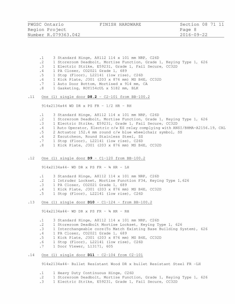
PWGSC Ontario FINISH HARDWARE Section 08 71 11 Region Project Page 8 Number R.079363.042 2016-09-22
.1 3 Standard Hinge, A8112 114 x 101 mm NRP, C26D
.2 1 Storeroom Deadbolt, Mortise Function, Grade 1, Keying Type 1, 626
.3 1 Electric Strike, E59231, Grade 1, Fail Secure, CC32D
.4 1 PA Closer, CO2021 Grade 1, 689
.5 1 Stop (Floor), L22141 (low rise), C26D
.6 1 Kick Plate, J301 (203 x 876 mm) MS B4E, CC32D
.7 1 Auto Door Bottom, Mortised x 914 mm, CA
.8 1 Gasketing, ROY154cUL x 5182 mm, BLK .11 One (1) single door D8.2 – C2-101 from BB-100.2
914x2134x44 WD DR x PS FR – 1/2 HR - RH
.1 3 Standard Hinge, A8112 114 x 101 mm NRP, C26D
.2 1 Storeroom Deadbolt, Mortise Function, Grade 1, Keying Type 1, 626
.3 1 Electric Strike, E59231, Grade 1, Fail Secure, CC32D
.4 1 Auto Operator, Electric c/w ES relay complying with ANSI/BHMA-A2156.19, CAL
.5 2 Actuator 152.4 mm round c/w blue wheelchair symbol, SS
.6 2 Escutcheon, Round Stainless Steel, SS
.7 1 Stop (Floor), L22141 (low rise), C26D
.8 1 Kick Plate, J301 (203 x 876 mm) MS B4E, CC32D .12 One (1) single door D9 – C1-120 from BB-100.2
914x2134x44- WD DR x PS FR – ¾ HR - LH
.1 3 Standard Hinge, A8112 114 x 101 mm NRP, C26D
.2 1 Intruder Lockset, Mortise Function F34, Keying Type 1,626
.3 1 PA Closer, CO2021 Grade 1, 689
.4 1 Kick Plate, J301 (203 x 876 mm) MS B4E, CC32D
.5 1 Stop (Floor), L22141 (low rise), C26D .13 One (1) single door D10 – C1-124 - from BB-100.2
914x2134x44- WD DR x PS FR – ¾ HR - RH
.1 3 Standard Hinge, A8112 114 x 101 mm NRP, C26D
.2 1 Storeroom Deadbolt Mortise Lockset, Keying Type 1, 626
.3 1 Interchangeable core(To Match Existing Base Building System), 626
.4 1 PA Closer, CO2021 Grade 1, 689
.5 1 Kick Plate, J301 (203 x 876 mm) MS B4E, CC32D
.6 1 Stop (Floor), L22141 (low rise), C26D
.7 1 Door Viewer, L13171, 605 .14 One (1) single door D11 – C2-104 from C2-101
914x2134x44- Bullet Resistant Wood DR x bullet Resistant Steel FR –LH
.1 1 Heavy Duty Continuous Hinge, C26D
.2 1 Storeroom Deadbolt, Mortise Function, Grade 1, Keying Type 1, 626
.3 1 Electric Strike, E59231, Grade 1, Fail Secure, CC32D
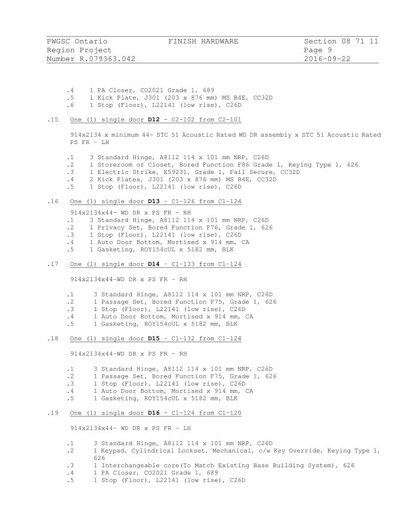
PWGSC Ontario FINISH HARDWARE Section 08 71 11 Region Project Page 9 Number R.079363.042 2016-09-22
.4 1 PA Closer, CO2021 Grade 1, 689
.5 1 Kick Plate, J301 (203 x 876 mm) MS B4E, CC32D
.6 1 Stop (Floor), L22141 (low rise), C26D .15 One (1) single door D12 – C2-102 from C2-101
914x2134 x minimum 44- STC 51 Acoustic Rated WD DR assembly x STC 51 Acoustic Rated PS FR - LH
.1 3 Standard Hinge, A8112 114 x 101 mm NRP, C26D
.2 1 Storeroom or Closet, Bored Function F86 Grade 1, Keying Type 1, 626
.3 1 Electric Strike, E59231, Grade 1, Fail Secure, CC32D
.4 2 Kick Plates, J301 (203 x 876 mm) MS B4E, CC32D
.5 1 Stop (Floor), L22141 (low rise), C26D .16 One (1) single door D13 – C1-126 from C1-124
914x2134x44- WD DR x PS FR - RH .1 3 Standard Hinge, A8112 114 x 101 mm NRP, C26D .2 1 Privacy Set, Bored Function F76, Grade 1, 626 .3 1 Stop (Floor), L22141 (low rise), C26D .4 1 Auto Door Bottom, Mortised x 914 mm, CA .5 1 Gasketing, ROY154cUL x 5182 mm, BLK
.17 One (1) single door D14 – C1-133 from C1-124
914x2134x44-WD DR x PS FR - RH
.1 3 Standard Hinge, A8112 114 x 101 mm NRP, C26D
.2 1 Passage Set, Bored Function F75, Grade 1, 626
.3 1 Stop (Floor), L22141 (low rise), C26D
.4 1 Auto Door Bottom, Mortised x 914 mm, CA
.5 1 Gasketing, ROY154cUL x 5182 mm, BLK .18 One (1) single door D15 – C1-132 from C1-124
914x2134x44-WD DR x PS FR - RH
.1 3 Standard Hinge, A8112 114 x 101 mm NRP, C26D
.2 1 Passage Set, Bored Function F75, Grade 1, 626
.3 1 Stop (Floor), L22141 (low rise), C26D
.4 1 Auto Door Bottom, Mortised x 914 mm, CA
.5 1 Gasketing, ROY154cUL x 5182 mm, BLK .19 One (1) single door D16 – C1-124 from C1-120
914x2134x44- WD DR x PS FR - LH
.1 3 Standard Hinge, A8112 114 x 101 mm NRP, C26D
.2 1 Keypad, Cylindrical Lockset, Mechanical, c/w Key Override, Keying Type 1, 626
.3 1 Interchangeable core(To Match Existing Base Building System), 626
.4 1 PA Closer, CO2021 Grade 1, 689
.5 1 Stop (Floor), L22141 (low rise), C26D

PWGSC Ontario FINISH HARDWARE Section 08 71 11 Region Project Page 10 Number R.079363.042 2016-09-22 .20 One (1) single door D17 – C1-131 from C1-124
914x2134x44- WD DR x PS FR - RH
.1 3 Standard Hinge, A8112 114 x 101 mm NRP, C26D
.2 1 Passage Set, Bored Function F75, Grade 1, 626
.3 1 Stop (Floor), L22141 (low rise), C26D
.4 1 Auto Door Bottom, Mortised x 914 mm, CA
.5 1 Gasketing, ROY154cUL x 5182 mm, BLK
.21 One (1) single door D18 – BB-100.3 from BB-100.2
914x2134x44- WD DR x PS FR - RH
.1 3 Standard Hinge, A8112 114 x 101 mm NRP, C26D
.2 1 Keypad Cylindrical Lockset, Mechanical, c/w Key Override and Privacy, Keying Type 3, 626
.3 1 Interchangeable core, keyed unique.
.4 1 Stop (Floor), L22161 (normal rise), C26D
.5 2 Kick Plates, J301 (203 x 876 mm) MS B4E, CC32D .22 One (1) single door D19 – C1-130 from C1124
914x2134x44-WD DR x PS FR - LH
.1 3 Standard Hinge, A8112 114 x 101 mm NRP, C26D
.2 1 Passage Set, Bored Function F75, Grade 1, 626
.3 1 Stop (Floor), L22141 (low rise), C26D
.4 1 Auto Door Bottom, Mortised x 914 mm, CA
.5 1 Gasketing, ROY154cUL x 5182 mm, BLK .23 One (1) single door D20 – C1-128 from C1-124
914x2134x44-WD DR x PS FR - RH
.1 3 Standard Hinge, A8112 114 x 101 mm NRP, C26D
.2 1 Passage Set, Bored Function F75, Grade 1, 626
.3 1 Stop (Floor), L22141 (low rise), C26D
.4 1 Auto Door Bottom, Mortised x 914 mm, CA
.5 1 Gasketing, ROY154cUL x 5182 mm, BLK .24 One (1) single door D21 – C1-128 from C1-124
914x2134x44-WD DR x PS FR - RH
.1 3 Standard Hinge, A8112 114 x 101 mm NRP, C26D
.2 1 Classroom Lockset, Bored Function F84 Grade 1, Keying Type 1, 626
.3 1 Stop (Floor), L22141 (low rise), C26D
.4 1 Auto Door Bottom, Mortised x 914 mm, CA
.5 1 Gasketing, ROY154cUL x 5182 mm, BLK .25 One (1) single door D22 – C1-121 from C1-120

PWGSC Ontario FINISH HARDWARE Section 08 71 11 Region Project Page 11 Number R.079363.042 2016-09-22
914x2134x44-WD DR x PS FR - RH
.1 3 Standard Hinge, A8112 114 x 101 mm NRP, C26D
.2 1 Classroom Lockset, Bored Function F84 Grade 1, Keying Type 1, 626
.3 1 Stop (Floor), L22141 (low rise), C26D
.4 1 Auto Door Bottom, Mortised x 914 mm, CA
.5 1 Gasketing, ROY154cUL x 5182 mm, BLK .26 One (1) single door D23 – C1-125 from C1-122
914x2134x44- HM DR x PS FR – ¾ HR - RH
.1 3 Standard Hinge, A8112 114 x 101 mm NRP, C26D
.2 1 Storeroom Deadbolt Mortise Lockset, Keying Type 3, 626
.3 1 PA Closer, CO2021 Grade 1, 689
.4 1 Stop (Floor), L22161 (normal rise), C26D
.27 One (1) single door D24 – C1-134 from C1-124
914x2134x44- HM DR x PS FR – ¾ HR - LH
.1 3 Standard Hinge, A8112 114 x 101 mm NRP, C26D
.2 1 Storeroom Deadbolt Mortise Lockset, Keying Type 3, 626
.3 1 PA Closer, CO2021 Grade 1, 689
.4 1 Stop (Floor), L22161 (normal rise), C26D
.28 One (1) single door D25 – C1-135 from C1-124
914x2134x44-WD DR x PS FR - RH
.1 3 Standard Hinge, A8112 114 x 101 mm NRP, C26D
.2 1 Passage Set, Bored Function F75, Grade 1, 626
.3 1 Stop (Floor), L22161 (normal rise), C26D
.28 One (1) Double door D26 – BB-100.1
.1 Existing door to remain as is.
.29 One (1) Sigle door D27 – BB-100.2
.1 Existing door to remain as is.
.30 One (1) single door D28 – CRA-138 from BB-100.1
914x2134x44-WD DR x PS FR - LH
.1 Electronic security monitoring devises and access control for this door to be provided by Chubb Edwards. Coordinate with Departmental Representative and Div. 26 scope of work.
.2 Reinstall existing hardware.
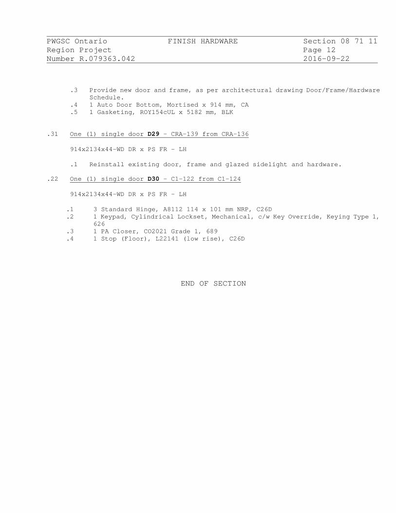
PWGSC Ontario FINISH HARDWARE Section 08 71 11 Region Project Page 12 Number R.079363.042 2016-09-22
.3 Provide new door and frame, as per architectural drawing Door/Frame/Hardware Schedule.
.4 1 Auto Door Bottom, Mortised x 914 mm, CA
.5 1 Gasketing, ROY154cUL x 5182 mm, BLK
.31 One (1) single door D29 – CRA-139 from CRA-136
914x2134x44-WD DR x PS FR - LH
.1 Reinstall existing door, frame and glazed sidelight and hardware.
.22 One (1) single door D30 – C1-122 from C1-124
914x2134x44-WD DR x PS FR - LH
.1 3 Standard Hinge, A8112 114 x 101 mm NRP, C26D
.2 1 Keypad, Cylindrical Lockset, Mechanical, c/w Key Override, Keying Type 1, 626
.3 1 PA Closer, CO2021 Grade 1, 689
.4 1 Stop (Floor), L22141 (low rise), C26D
END OF SECTION

PWGSC Ontario LOW ENERGY POWER Section 08 71 12 Region Project DOOR OPERATOR Page 1 Number R.079363.042 2016-09-22
PART 1 - GENERAL 1.1 RELATED SECTIONS
.1 Read and be governed by the conditions of the Contract and specifications of Division 01.
.2 Section 08 11 13: Steel hollow metal doors, frames and screens.
.3 Section 08 14 11: Wood doors.
.4 Section 08 71 11: Door hardware.
.5 Division 26: Electrical service and related wiring/ conduit/ BX/
backboxes and connection to building security system. 1.2 REFERENCES
.1 ANSI/BHMA-A156.10-2011, Power Operated Pedestrian Doors (for definition of terms used in A156.19).
.2 ANSI/BHMA-A156.19-2013, Power Assist and Low Energy Power-Operated
Doors.
.3 CSA B651-12, Accessible Design for the Built Environment.
.4 NFPA 80-2013, Standard for Fire Doors and Other Opening Protectives. 1.3 PRODUCT DATA SHEETS
.1 Submit one copy of product data sheets in accordance with Sections 01 33 00 and 01 78 00 for each item specified below.
.2 Product data sheets shall consist of catalogue cuts, product number,
manufacturer's name and phone number, finish and reference identification to specified standard. .1 Where data sheets list multiple models or configurations on the same sheet, indicate which model is proposed.
.3 Submit data sheets indicating that operator conforms with all the
requirements of ANSI/BHMA-A156.19. Highlight the following data: .1 Opening and closing speeds are adjustable in accordance with requirements of Table 1. .2 Doors require a force of not more than 67 N to open or stop door movement.
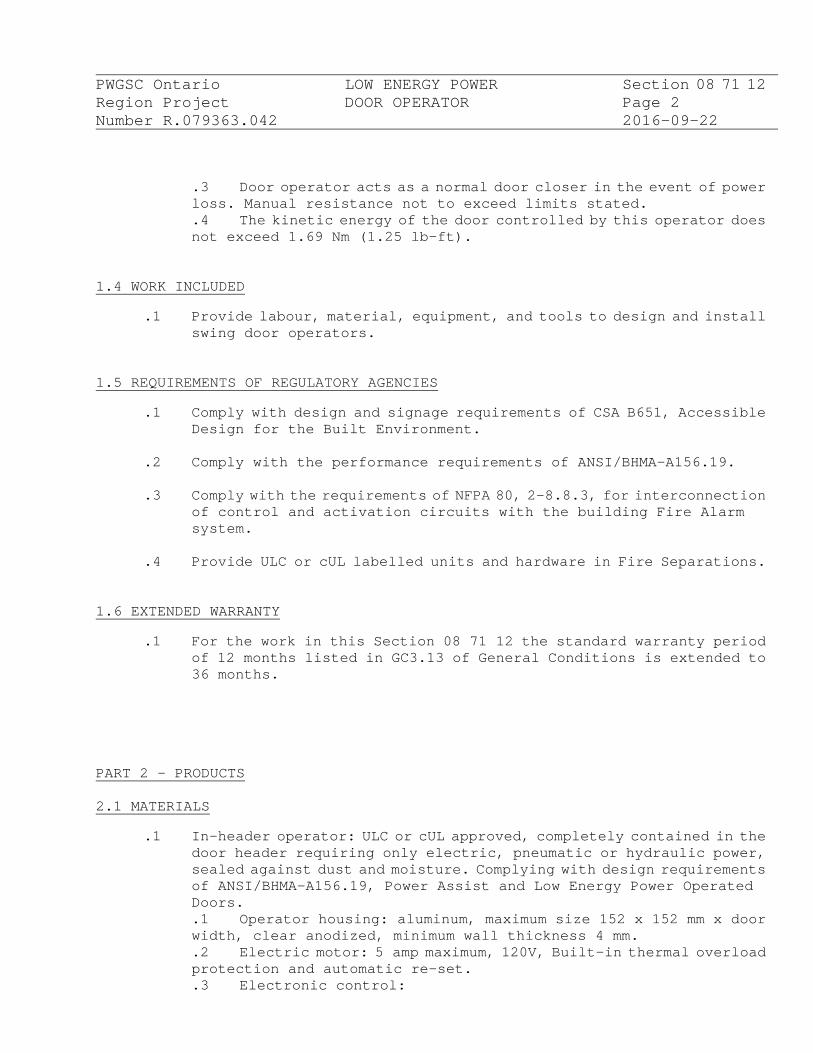
PWGSC Ontario LOW ENERGY POWER Section 08 71 12 Region Project DOOR OPERATOR Page 2 Number R.079363.042 2016-09-22
.3 Door operator acts as a normal door closer in the event of power loss. Manual resistance not to exceed limits stated. .4 The kinetic energy of the door controlled by this operator does not exceed 1.69 Nm (1.25 lb-ft).
1.4 WORK INCLUDED
.1 Provide labour, material, equipment, and tools to design and install swing door operators.
1.5 REQUIREMENTS OF REGULATORY AGENCIES
.1 Comply with design and signage requirements of CSA B651, Accessible Design for the Built Environment.
.2 Comply with the performance requirements of ANSI/BHMA-A156.19.
.3 Comply with the requirements of NFPA 80, 2-8.8.3, for interconnection
of control and activation circuits with the building Fire Alarm system.
.4 Provide ULC or cUL labelled units and hardware in Fire Separations.
1.6 EXTENDED WARRANTY
.1 For the work in this Section 08 71 12 the standard warranty period of 12 months listed in GC3.13 of General Conditions is extended to 36 months.
PART 2 - PRODUCTS 2.1 MATERIALS
.1 In-header operator: ULC or cUL approved, completely contained in the door header requiring only electric, pneumatic or hydraulic power, sealed against dust and moisture. Complying with design requirements of ANSI/BHMA-A156.19, Power Assist and Low Energy Power Operated Doors. .1 Operator housing: aluminum, maximum size 152 x 152 mm x door width, clear anodized, minimum wall thickness 4 mm. .2 Electric motor: 5 amp maximum, 120V, Built-in thermal overload protection and automatic re-set. .3 Electronic control:

PWGSC Ontario LOW ENERGY POWER Section 08 71 12 Region Project DOOR OPERATOR Page 3 Number R.079363.042 2016-09-22
.1 Self-contained, solid state integrated circuit for controlling the operations and switching of the door operator. .2 Provide low voltage power supply for all means of actuation. .3 Provide adjustable time delay of 1 to 60 seconds.
.4 Single acting operation: .1 Maintain constant opening pressure. .2 Provide individual adjustment for opening and closing speeds and variable time delay. Provide separate adjustable creep speed/latch speed features on closing. .3 Provide manual door closer function in the event of power failure. .4 Force required for manual door operation is independent of opening speed setting. .5 Provide closing function that overcomes air pressure differences and returns door to full close and latch. .6 Provide recycle operation from any intermediate door position.
.5 Time delay circuit:
.1 Provide time delay operation to allow electric strike to release prior to initiating opening cycle.
.6 Activating devices:
.1 Provide controls that cause door to open instantly when device located on approach side of door is actuated; hold door in open position, and cause door to close - re-actuation of opening impulse overrides such operation. .2 Provide the following actuating devices:
.1 Press wall or jamb mount switches, 2 per door: wheelchair logo, colour blue, stainless steel, weatherproof at exterior locations. .2 Keyed on off switch with pilot light for maintenance.
.2 Power supply: ULC approved, rated for and compatible with electric
strike.
.3 Key switch: rated for and compatible with Exit Device, complete with latch bolt status indicator lights.
.4 Accessories: signage required by ANSI, stainless steel plate press
buttons.
PWGSC Ontario LOW ENERGY POWER Section 08 71 12 Region Project DOOR OPERATOR Page 4 Number R.079363.042 2016-09-22 PART 3 - EXECUTION
3.1 INSTALLATION
.1 Install swing door operator in accordance with manufacturer's recommendations using factory authorized and trained personnel.
.2 Install wall switches at 900 - 1000 mm above floor.
.3 Install keyed on/off switch where directed by Departmental
Representative.
.4 Conceal wiring and fasteners.
.5 Field adjust opening and closing times in accordance with Table 1, ANSI/BHMA-A156.19.
3.2 HARDWARE SCHEDULE
.1 Refer to Hardware Schedule for doors requiring Power Door Operators.
END OF SECTION

PWGSC Ontario GLAZING Section 08 80 00 Region Project Page 1 Number R.079363.042 2016-09-22
PART 1 - GENERAL 1.1 RELATED SECTIONS
.1 Read and be governed by the conditions of the Contract and specifications of Division 01.
.2 Section 08 11 13: Steel Hollow Metal Doors, Frames, and Screens.
1.2 SUBMITTALS
.1 Submit one representative sample type of glazing film in accordance with Section 01 33 00.
.2 Approved sample may be installed as part of completed Work.
.3 Submit maintenance data for glazing film to Departmental Representative in
accordance with Section 01 78 00. 1.3 QUALITY ASSURANCE
.1 Qualifications of glazing film applicator: trained glazing film applicator.
.2 Glazing film inspection: manufacaturer's representative shall view the film at a distance of 3 m (10 feet) at angles up to 45 degrees from either side of the glass during regular daylight conditions (not in direct sunlight). To be accepted the film itself shall not appear distorted. Submit manufacturer's written inspection report to Departmental Representative.
PART 2 - PRODUCTS 2.1 MATERIALS
.1 Laminated safety glass (GL-1): to CAN/CGSB-12.1-M90, Type 1-laminated, Class B of thickness indicated, laminated film thickness 0.06 mm. Transparent.
.2 Tempered safety glass (GL-2): to CAN/CGSB-12.1-M90, Type 2-tempered, Class
B of thickness indicated, laminated film thickness 0.06 mm. Transparent.
.3 Mirror: to CAN/CGSB-12.5-M86, Type 1B, polished plate or float glass, high
PWGSC Ontario GLAZING Section 08 80 00 Region Project Page 2 Number R.079363.042 2016-09-22
humidity use, 6 x 400 x 550 mm with stainless steel frame.
.4 Setting blocks: neoprene, Shore "A" 80 durometer hardness to ASTM D2240-05(2010), 100 x 6 mm x width to suit glass.
.5 Glazing tape: preformed butyl with continuous spacer, Shore "A" 10-15
durometer hardness, paper release, black colour, 3 x 9.5 mm.
.6 Gasket: black neoprene to ASTM C542-05(2011), "U" cavity type with lock strip.
.7 Sealant: one part silicone to ASTM C920-11, Type S, Grade NS, Class 50.
.8 Glazing film: to Section 08 87 543. .9 UL 752 Standard Bullet Resistant Polycarbonate Security Glass for W7:
1. 31.8 mm thick, UL 752 Standard, Level 3 Bullet Resistant laminated Acrylic/Polycarbonate glass.
2. Arched speak hole and backer, 31.8 mm thick, UL 752 Standard, Level 3 Bullet Resistant laminated Acrylic/Polycarbonate glass.
PART 3 - EXECUTION 3.1 INSTALLATION
.1 Glass: .1 Clean and dry surfaces. .2 Apply glazing tape to fixed stops. .3 Place setting blocks at 1/3 points. .4 Set glass on setting blocks against tape. .5 Apply glazing tape to glass. .6 Install stops. .7 Apply sealant behind stop and tool to smooth surface. .8 Install glass in aluminum doors and screens with neoprene gasket.
.2 Mirror:
.1 Install over washroom lavatories, 1000 mm above floor unless otherwise indicated. .2 Conceal fasteners.
END OF SECTION

PWGSC Ontario GLAZING FILMS Section 08 87 54 Region Project Page 1 Number R.079363.042 2016-09-22
PART 1 - GENERAL 1.1 RELATED SECTIONS
.1 Read and be governed by the conditions of the Contract and specifications of Division 01.
.2 Section 08 80 00 - Glazing.
1.2 REFERENCES
.1 American National Standards Institute (ANSI)
.1 ANSI Z97.1-1984(R1994), Glazing Materials Used in Buildings, Safety Performance Specifications and Methods of Test.
.2 American Society for Testing and Materials (ASTM)
.1 ASTM C1115-06(2011), Standard Specification for Dense Elastomeric Silicone Rubber Gaskets and Accessories. .2 ASTM D882-10, Standard Test Method for Tensile Properties of Thin Plastic Sheeting. .3 ASTM D1044-08, Standard Test Method for Resistance of Transparent Plastics to Surface Abrasion. .4 ASTM E84-11b, Standard Test Method for Surface Burning Characteristics of Building Materials.
.3 International Window Film Association (IWFA)
.2 IWFA Visual Quality Standard for Applied Window Film 1999. 1.3 SAMPLES
.1 Submit one representative sample each pattern and type of glazing film in accordance with Section 01 33 00. Submit one 300 x 300 mm sample of film installed on 6 mm thick clear plate glass.
1.4 SHOP DRAWINGS
.1 Submit shop drawings in accordance with Section 01 33 00. 1.5 QUALITY ASSURANCE
.1 Qualifications of glazing film and frame applicator: trained, approved and certified by glazing film manufacturer. Submit proof of
PWGSC Ontario GLAZING FILMS Section 08 87 54 Region Project Page 2 Number R.079363.042 2016-09-22
certification in writing to Departmental Representative in accordance with Sections 01 33 00.
1.6 DELIVERY, STORAGE AND HANDLING
.1 Deliver, store and handle materials in accordance with Section 01 61 00.
.2 Provide and maintain dry, off-ground weatherproof storage.
.3 Store rolls of security film flat on cross supports. Do not stand rolls
of film on end.
.4 Remove only in quantities required for same day use.
.5 Store materials in accordance with manufacturers written instructions.
1.7 WASTE MANAGEMENT AND DISPOSAL
.1 Separate and recycle waste materials in accordance with Section 01 74 20 and with Waste Reduction Workplan.
.2 Place materials defined as hazardous or toxic waste in designated
containers.
.3 Ensure emptied containers are sealed and stored safely for disposal away from children.
1.8 ENVIRONMENTAL AND SAFETY REQUIREMENTS
.1 Comply with requirements of Workplace Hazardous Materials Information System (WHMIS) regarding use, handling, storage, and disposal of hazardous materials; and regarding labelling and provision of material safety data sheets acceptable to Canada Labour Code.
1.9 WARRANTY
.1 Work of this Section 08 87 54 the 12 months warranty period prescribed in GC3.13 of General Conditions is extended to 5 years.
.2 Ensure warranty includes items as follows:
.1 Maintain adhesion properties without blistering, bubbling or delaminating from glass.

PWGSC Ontario GLAZING FILMS Section 08 87 54 Region Project Page 3 Number R.079363.042 2016-09-22
.2 Maintain appearance without discolouration.
.3 Remove, replace and reapply defective materials.
.4 In event of product failure under warranty terms, remove and re-apply film without glass replacement at no cost to Departmental Representative.
1.10 MAINTENANCE DATA
.1 Provide operation and maintenance data for window film for incorporation into manual specified in Section 01 78 00.
PART 2 - PRODUCTS 2.1 MANUFACTURER
.1 Use manufacturers who are members of International Window Film Association (IWFA).
2.2 MATERIALS
.1 Sidelight Decorative Film: digitally cuttable polyster. .1 Total thickness of installed film: 0.07 mm. .2 Flame Spread and Smoke Development Classification: Class A. .3 Tensile Strength: 200-400 N/25mm. .4 Adhesive: high mass pressure sensitive, acrylic base. .5 Colour: white. .6 Opacity: translucent. .7 Style and Pattern: As selected by Departmental Representative.
.2 Exterior Windows Safety and Security Window Film: optically clear glass
shatter resistant and abrasion resistant window film, applied to the interior window. .1 The film material shall consist of three laminated film layers of
optically clear polyester and contain a durable abrasion resistant coating over one surface, and a U V stabilized pressure sensitive adhesive on the other.
.3 Break and Entry complete testing: ULC 332, UL 972 and EN 356 tested.
.2 Total thickness of installed film: 0.36 mm.
.3 Flame Spread and Smoke Development Classification: Class A.
.4 Tensile Strengthto ASTM D882: 173 N/mm2 (25,000 psi)
.5 Break Strength to ASTM D882: 25,000 psi (350 lbs per inch width)
.6 Percent elongation at Break to ASTM D882: greater than 100%
.7 Adhesive: high mass pressure sensitive weatherable acrylate adhesive.
.8 Opacity: Tinted.
PWGSC Ontario GLAZING FILMS Section 08 87 54 Region Project Page 4 Number R.079363.042 2016-09-22
PART 3 - EXECUTION 3.1 INSTALLERS
.1 Use only manufacturer authorized applicators who are also members of the International Window Film Association (IWFA) and have achieved accredited status as "Safety & Security Film Specialists"
3.2 PREPARATION
.1 Clean glass before beginning installation using neutral cleaning solution.
.2 Ensure no deleterious material adheres to glass by balding surface
of glass using industrial razors.
.3 Ensure dust, grease, and chemical residue are removed from surface of glass before installation of film.
.4 Examine glass under natural daylight and identify cracks, blisters,
bubbles, discoloration, edge defects or other anomalies that may cause, film to delaminate, or vision transparency or distortion problems. Report findings to Departmental Representative.
.5 Proceed with Work only after receipt of written approval from
Departmental Representative.
.6 Before beginning Work, place absorbent material on window sill or at sash frame to absorb moisture accumulation generated by film application.
3.3 INSTALLATION
.1 Cut film edges straight and square.
.2 Apply and attach film to glass in accordance with manufacturer's written instructions.
.3 Mechanically anchor film to window frame, where specified, in
accordance with manufacturers written instructions.
.4 Splicing: .1 Splice film only when glass is greater in width than film. .2 Splice film only after receipt of written approval from Departmental Representative.
PWGSC Ontario GLAZING FILMS Section 08 87 54 Region Project Page 5 Number R.079363.042 2016-09-22
.3 Use butt factory edges only.
.5 Use clean, clear water to remove protective water soluble coating on adhesive side of film.
.6 Use only water and film slip solution on glass to facilitate
positioning of film.
.7 Ensure removal of excess water from between film and glass.
.8 Remove left over material form work area and return work area to original condition.
3.4 INSPECTION
.1 Return to work place after 30 days but no longer than 40 days for final cleaning and inspection of installed film.
.2 Ensure finished surface of film is vision free of blisters, bubbles,
tears, scratches, edge defects, delaminating or vision distortion when viewed under natural daylight from 2.0 m minimum.
.3 Remove and replace film that continues to show blisters, bubbles,
tears, scratches, edge defects or vision distortion in film when viewed under natural daylight from 2.0 m minimum after 30 day period.
3.5 FINAL CLEANING
.1 Wash interior and exterior of each window and film using cleaning solution recommended by film manufacturer.
3.6 MAINTENANCE
.1 Follow manufacturer’s written instructions for care and maintenance of security film.
.2 Use only cleaning solution recommended by manufacturer for regularly
scheduled cleaning of security film.
END OF SECTION

PWGSC Ontario PARTITIONS Section 09 21 99 Region Project Page 1 Number R.079363.042 2016-09-22 _
Part 1 General
1.1 REFERENCES
.1 ASTM International
.1 ASTM C1396/C1396M-09a, Standard Specification for Gypsum Wallboard.
.2 ASTM C475/C475M-02(2007), Standard Specification for Joint Compound and Joint Tape for Finishing Gypsum Board.
.3 ASTM C645-09a, Standard Specification for Non-structural Steel Framing Members.
.4 ASTM C754-09a, Standard Specification for Installation of Steel Framing Members to Receive Screw-Attached Gypsum Panel Products.
.5 ASTM C840-08, Standard Specification for Application and Finishing of Gypsum Board.
.6 ASTM C954-10, Standard Specification for Steel Drill Screws for the Application of Gypsum Panel Products or Metal Plaster Bases to Steel Studs from 0.033 in. (0.84 mm) to 0.122 in. (2.84 mm) in Thickness.
.7 ASTM C1047-10, Standard Specification for Accessories for Gypsum Wallboard and Gypsum Veneer Base.
.2 South Coast Air Quality Management District (SCAQMD), California State, Regulation XI. Source Specific Standards
.1 SCAQMD Rule 1168-A2005, Adhesives and Sealants Applications.
.3 Underwriters' Laboratories of Canada (ULC)
.1 CAN/ULC-S102-07, Standard Method of Test for Surface Burning Characteristics of Building Materials and Assemblies.
1.2 ACTION AND INFORMATIONAL SUBMITTALS
.1 Submit in accordance with Section 01 33 00 - Submittal Procedures.
.2 Product Data:
.1 Submit manufacturer's instructions, printed product literature and data sheets for gypsum, framing, sealants and include product characteristics, performance criteria, physical size, finish and limitations.
.3 Test and Evaluation Reports: submit test reports in accordance with Section 01 45 00 - Quality Control, from approved independent testing laboratory, certifying partition system complies with fire-resistance rating as specified.

PWGSC Ontario PARTITIONS Section 09 21 99 Region Project Page 2 Number R.079363.042 2016-09-22 _
1.3 DELIVERY, STORAGE AND HANDLING
.1 Deliver, store and handle materials in accordance with Section 01 61 00 - Common Product Requirements and with manufacturer's written instructions.
.2 Delivery and Acceptance Requirements: deliver materials to site in original factory packaging, labelled with manufacturer's name and address.
.3 Storage and Handling Requirements:
.1 Store materials indoors in dry location and in accordance with manufacturer's recommendations in clean, dry, well-ventilated area.
.2 Store materials inside, level, under cover. Protect from weather, damage from construction operations and other causes, in accordance with manufacturer's printed instructions.
.3 Handle materials to prevent damage to edges or surfaces. Protect metal accessories and trim from being bent or damaged.
.4 Store and protect partition materials from nicks, scratches, and blemishes.
.5 Replace defective or damaged materials with new.
Part 2 Products
2.1 MATERIALS
.1 Performance / Design Criteria:
.1 Partition assembly to be non-combustible construction fire resistance rated where indicated.
.2 Non-structural Metal Framing:
.1 Non-load bearing channel stud framing: to ASTM C645, roll formed from 1.3 mm thickness hot dipped galvanized steel sheet, for screw attachment of gypsum board. Knock-out service holes at 460 mm centres.
.2 Floor and ceiling tracks: to ASTM C645, in widths to suit stud sizes, 41 mm flange height.
.3 Metal channel stiffener: 19 x 1.4 mm thick cold rolled steel, coated with rust inhibitive coating.
.3 Gypsum Board:
PWGSC Ontario PARTITIONS Section 09 21 99 Region Project Page 3 Number R.079363.042 2016-09-22 _
.1 Standard board: to ASTM C1396/C1396M, regular, 16 mm, 1200 mm wide x maximum practical length, ends square cut, edges tapered.
.2 Metal furring runners, hangers, tie wires, inserts, anchors: to ASTM C1047.
.3 Drywall furring channels: 0.5 mm core thickness galvanized steel channels for screw attachment of gypsum board.
.4 Steel screws: to ASTM C954.
.5 Casing beads, corner beads, control joints and edge trim: to ASTM C1047, zinc-coated by electrolytic process, 0.5 mm base thickness, perforated flanges, one piece length per location.
.4 Security Mesh:
.1 Expanded steel mesh, Flattened, 19 mm x 9 Gauge.
.5 Bullet resistant Fiber glass panels:
.1 UL-752 Listed and NIJ0108.1 Tested, Non-Spalling, Lightweight, Heat pressed resin impregnated fibreglass layers, 11.12 mm thick x 1220 mm x 2438 mm panel size. Nominal weight 2.441 gr. per CM2. UL-752 Compliance NIJ-II & IIIA UL-3, impact velocity-1350 feet/second for .44 MAG 240 gr. Lead; impact velocity-1400 feet/second for 9 mm 124 gr. FMJ. 3 shots.
1. Acceptable product: Bullet Guard Corporation, www.bulletguard.com, item # BGAA-03, Bullet Resistant Wall & Cabinet Armor.
2.2 ACCESSORIES
.1 Sealants: to ASTM C475.
.1 VOC limit 250 g/L maximum to SCAQMD Rule 116. .2 Steel rivets and washers. .1 5mm diameter steel rivet. .2 38mm diameter steel washer.
Part 3 Execution
3.1 EXAMINATION
.1 Verification of Conditions: verify conditions of substrates previously installed under other Sections or Contracts are acceptable for product installation in accordance with

PWGSC Ontario PARTITIONS Section 09 21 99 Region Project Page 4 Number R.079363.042 2016-09-22 _
manufacturer's written instructions prior to partition installation.
.1 Inform Departmental Representative of unacceptable conditions immediately upon discovery.
.2 Proceed with installation only after unacceptable conditions have been remedied.
3.2 ERECTION OF FRAMING
.1 Install steel framing members to receive screw-attached gypsum board in accordance with ASTM C754 except where specified otherwise.
.2 Align partition tracks at floor and ceiling and secure at 600 mm on centre maximum.
.3 Place studs vertically at 300 mm on centre and maximum of 12 mm from abutting walls, and at each side of openings and corners. Position studs in tracks at floor and ceiling. Cross brace steel studs as required to provide rigid installation to manufacturer's instructions.
.4 Erect metal studding to tolerance of 1:1000.
.5 Co-ordinate simultaneous erection of studs with installation of service lines. When erecting studs ensure web openings are aligned.
.6 Include two studs extending from floor to ceiling at each side of openings wider than stud centres specified. Secure studs together, 50 mm apart using column clips or other approved means of fastening placed alongside frame anchor clips.
.7 Install heavy gauge single jamb studs at openings.
.8 Erect track at head of door/window openings and sills of sidelight/window openings to accommodate intermediate studs. Secure track to studs at each end, in accordance with manufacturer's instructions. Install intermediate studs above and below openings in same manner and spacing as wall studs.
.9 Include 40mm stud or furring channel secured between studs for attachment of fixtures behind lavatory basins, toilet and bathroom accessories, and other fixtures including grab bars and towel rails, attached to steel stud partitions.
.10 Install steel studs or furring channel between studs for attaching electrical and other boxes.
.11 Extend partitions to ceiling height except where indicated.
.12 Maintain clearance under beams and structural slabs to avoid transmission of structural loads to studs. Use double track slip joint.
.13 Install continuous insulating strips to isolate studs from uninsulated surfaces.
PWGSC Ontario PARTITIONS Section 09 21 99 Region Project Page 5 Number R.079363.042 2016-09-22 _
.14 Install horizontal stud framing at stud space adjacent door at 1200mm and 2450mm above finish floor.
.15 Connect all stud framing to top and bottom track with steel rivets.
.16 Secure bottom track to floor slab with double expanding mechanical fastener at 300mm o.c. (self tapping screws is not acceptable).
.17 Provide double stud at inside corners to support interior finish.
3.3 ERECTION OF GYPSUM BOARD AND ACCESSORIES
.1 Do application and finishing of gypsum board in accordance with ASTM C840 except where specified otherwise.
.2 Erect hangers and runner channels for suspended gypsum board ceilings in accordance with ASTM C840 except where specified otherwise.
.3 Support light fixtures by providing additional ceiling suspension hangers within 150 mm of each corner and at maximum 600 mm around perimeter of fixture.
.4 Frame with furring channels, perimeter of openings for access panels, light fixtures, diffusers, grilles.
.5 Furr for gypsum board faced vertical bulkheads within and at termination of ceilings.
.6 Furr above suspended ceilings for gypsum board fire and sound stops and to form plenum areas as indicated.
.7 Install wall furring for gypsum board wall finishes in accordance with ASTM C840, except where specified otherwise.
.8 Install acoustical insulation and sealant in sound rated partitions to correspond with tested assembly.
.9 Install gypsum boards in direction that will minimize number of end-butt joints. Stagger end joints 250 mm minimum.
3.4 APPLICATION
.1 Apply gypsum board after bucks, anchors, blocking, sound attenuation, electrical and mechanical work are approved.
.2 Apply gypsum board to metal furring or framing using screw fasteners. Maximum spacing of screws 300 mm on centre.
3.5 INSTALLATION
.1 Erect accessories straight, plumb or level, rigid and at proper plane. Use full length pieces where practical. Make joints tight,
PWGSC Ontario PARTITIONS Section 09 21 99 Region Project Page 6 Number R.079363.042 2016-09-22 _
accurately aligned and rigidly secured. Mitre and fit corners accurately, free from rough edges. Secure at 150 mm on centre.
.2 Install casing beads around perimeter of suspended ceilings.
.3 Install casing beads where gypsum board butts against surfaces having no trim concealing junction and where indicated. Seal joints with sealant.
.4 Install insulating strips continuously at edges of gypsum board and casing beads abutting metal window and exterior door frames, to provide thermal break.
.5 Install access doors to electrical and mechanical fixtures specified in respective sections.
.1 Rigidly secure frames to furring or framing systems.
.6 Finish face panel joints and internal angles with joint system consisting of joint compound, joint tape and taping compound installed according to manufacturer's directions and feathered out onto panel faces.
.7 Finish corner beads, control joints and trim as required with two coats of joint compound and one coat of taping compound, feathered out onto panel faces.
.8 Fill screw head depressions with joint and taping compounds to bring flush with adjacent surface of gypsum board so as to be invisible after surface finish is completed.
.9 Completed installation to be smooth, level or plumb, free from waves and other defects and ready for surface finish.
3.6 ERECTION OF SECURITY MESH
.1 Secure mesh to all studs and to top and bottom track with steel rivet and washer at 200mm o.c. (screw attachment is not acceptable).
.2 Provide stud support to all edges of security mesh.
3.7 CLEANING
.1 Progress Cleaning: clean in accordance with Section 01 74 11 - Cleaning.
.1 Leave Work area clean at end of each day.
.2 Final Cleaning: upon completion remove surplus materials, rubbish, tools and equipment in accordance with Section 01 74 11 - Cleaning.

PWGSC Ontario PARTITIONS Section 09 21 99 Region Project Page 7 Number R.079363.042 2016-09-22 _
3.8 PROTECTION
.1 Protect installed products and components from damage during construction.
.2 Repair damage to adjacent materials caused by partition installation.
END OF SECTION

PWGSC Ontario TILING Section 09 30 14 Region Project Page 1 Number R.079363.042 2015-09-22
PART 1 - GENERAL 1.1 RELATED SECTIONS
.1 Read and be governed by the conditions of the Contract and specifications of Division 01.
1.2 REFERENCE STANDARDS
.1 American National Standards (ANSI) for the Installation of Ceramic Tile/ Ceramic Tile Institute of America (CTIOA): .1 ANSI A108/A118/A136.1-2011, Installation of Ceramic Tile.
.1 ANSI A108.1C, Contractors Option: Installation of Ceramic Tile in the Wet-Set Method with Portland Cement Mortar or Installation of Ceramic Tile on a Cured Portland Cement Mortar Bed with Dry-Set or Latex Portland Cement Mortar. .2 ANSI A108.5, Installation of Ceramic Tile with Dry-Set Portland Cement Mortar or Latex-Portland Cement Mortar. .3 ANSI A108.10, Installation of Grout in Tilework. .4 ANSI A118.1, Dry-Set Portland Cement Mortar. .5 ANSI A118.4, Latex Portland Cement Mortar. .6 ANSI A118.6, Ceramic Tile Grouts. .7 ANSI A137.1-2008, Specifications for Ceramic Tile
.2 International Standards Organization (ISO):
.1 ISO 13006-1998, Ceramic Tiles -- Definitions, Classification, Characteristics and Marking. .2 ISO 13007- Part 1: 2010: Ceramic tiles -- Grouts and adhesives; performance requirements for tile adhesives. .3 ISO 13007- Part 2: 2010: Ceramic tiles -- Grouts and adhesives; test methods for adhesives. .4 ISO 13007- Part 3: 2010: Ceramic tiles -- Grouts and adhesives; terms, definitions and specifications for grouts. .5 ISO 13007- Part 4: 2010: Ceramic tiles -- Grouts and adhesives; Test methods for grouts. .6 ISO 10545 Series:
.1 ISO 10545-2:1995/Cor 1:1997, Ceramic Tiles -- Part 2: Determination of Dimensions and Surface Quality. .2 ISO 10545-3:1995/Cor 1:1997, Ceramic Tiles -- Part 3: Determination of Water Absorption, Apparent Porosity, Apparent Relative Density and Bulk Density. .3 ISO 10545-4:2004, Ceramic Tiles - Part 4: Determination of Modulus of Rupture and Breaking Strength. .4 ISO 10545-6:1995, Ceramic Tiles -- Part 6: Determination of Resistance to Deep Abrasion for Unglazed Tiles. .5 ISO 10545-7:1996, Part 7: Determination of resistance to

PWGSC Ontario TILING Section 09 30 14 Region Project Page 2 Number R.079363.042 2015-09-22
surface abrasion for glazed tiles. .6 ISO 10545-8:1994, Ceramic Tiles -- Part 8: Determination of Linear Thermal Expansion. .7 ISO 10545-9:1996, Ceramic Tiles - Part 9: Determination of Resistance to Thermal Shock. .8 ISO 10545-10:1995, Ceramic Tiles -- Part 10: Determination of Moisture Expansion. .9 ISO 10545-12:1995/Cor 1:1997, Ceramic Tiles -- Part 12: Determination of Frost Resistance. .10 ISO 10545-13:1995, Ceramic Tiles -- Part 13: Determination of Chemical Resistance. .11 ISO 10545-14:1997, Ceramic Tiles -- Part 14: Determination of Resistance to Stains.
.3 American Society for Testing and Materials International (ASTM)
.1 ASTM C144-11, Standard Specification for Aggregate for Masonry Mortar. .2 ASTM C373-14a, Standard Test Method for Water Absorption, Bulk Density, Apparent Porosity, Apparent Porosity, and Apparent Specific Gravity of Fired Whiteware Products, Ceramic Tiles, and Glass Tiles. .3 ASTM C627-10, Standard Test Method for Evaluating Ceramic Floor Tile Installation Systems Using the Robinson-Type Floor Tester. .4 ASTM C1028-07e1, Test Method for Determining the Static Coefficient of Friction of Ceramic Tile and Other Like Surfaces by the Horizontal Dynamometer Pull-Meter Method.
.4 Canadian Standards Association (CSA International)
.1 CAN/CSA-A3000-13, Cementitious Materials Compendium (Consists of A3001, A3002, A3003, A3004 and A3005). .2 CAN/CSA-A3001-13, Cementitious Materials for Use in Concrete. .3 CSA B651-12, Accessible Design for the Built Environment.
.5 Terrazzo Tile and Marble Association of Canada (TTMAC) 1-800-201-8599,
905-660-9640, www.ttmac.com. .1 Hard Surface Maintenance Guide. .2 TTMAC Specification Guide 09 30 00 - Tile Installation Manual 2012/2014.
.6 Tile Council of North America (TCNA), 1-864-646-8453, www.tileusa.com.
.1 Handbook for Ceramic, Glass and Stone Tile Installation, 2011.
.7 CAN/CGSB-25.20-95, Surface Sealer Floors.
.8 CAN/CGSB-75.1-M88, Tile, Ceramic. 1.3 QUALITY ASSURANCE
.1 Execute work of this section only by a Subcontractor who has adequate plant, equipment, and skilled workers to perform it expeditiously, and is known to have been responsible for satisfactory installations similar

PWGSC Ontario TILING Section 09 30 14 Region Project Page 3 Number R.079363.042 2015-09-22
to that specified during a period of at least the immediate past 5 years.
.2 Subcontractor shall be a member company in good standing of the Terrazzo, Tile and Marble Association of Canada and have been a member for at least the past 5 years .
.3 Comply with TTMAC Manual - 2012/2014 Specification Guide 09300 Tile Installation Manual as produced by the Terrazzo, Tile and Marble Association of Canada.
1.4 SUBMITTALS
.1 Submit TTMAC Installation Detail No. or Tile Council of America Installation Detail No. or shop drawing showing installation for each tile specified.
.2 Submit list of materials suitable for sealing and finishing each tile
specified.
.3 Submit proof of each non-slip tile's conformance to CSA B651-12.
.4 Maintenance data:
.1 Submit maintenance instructions for inclusion in the maintenance manuals.
1.5 SAMPLES
.1 Submit samples in accordance with Section 01 33 00 – Submittal Procedures and Section 01 78 00 – Closeout Submittals.
.2 Submit full size samples of each type of tile specified. .3 Submit 2 complete sets of grout manufacturer's standard grout colour
samples demonstrating full range of grout colours for the purposes of colour selection by the Departmental Representative.
1.6 PRODUCT DATA SHEETS
.1 Environmental Conditions: Execute work of this section while temperature is maintained within safe working temperatures in accordance with manufacturer's installation instructions for a period of 72 hours before, during and following installation. Avoid concentrated or irregular heating during curing period.
.2 Protection: Protect work of this section against damage by work of other sections for a minimum of 72 hours after application of grouting

PWGSC Ontario TILING Section 09 30 14 Region Project Page 4 Number R.079363.042 2015-09-22
by prohibiting passage of traffic over tile. Do not immerse in water and protect tilework from freezing for at least 28 days after installation
1.7 ENVIRONMENTAL REQUIREMENTS
.1 Submit manufacturer's Product data sheets for Products proposed for use in the work of this section.
PART 2 - PRODUCTS 2.1 TILE PRODUCTS
.1 Porcelain tile (PCT): to ISO 10545 Series, glazed tile. .1 Slip resistance for floor tile: to ASTM C1028, wet and dry surface greater than 0.60. .2 Surface flatness: to ISO 10545-2, maximum ±0.4% and CSA B651. .3 Water absorption: to ISO 10545-3, 3.0%. .4 Breaking strength: to ISO 10545-4, >40 N/mm2. .5 Abrasion resistance: to ISO 10545-7, PEI II-IV. .6 Recycled content: Minimum 5% post-consumer recycled content, or minimum 5% pre-consumer recycled content. .7 Basis of design: Product: Nepal Series, distributed by Olympia Tile (or approved equal).
.1 Size: 30 x 60 cm.
.2 Colour: Cream.
.3 Finish: Matte .8 Grout: Latex-Portland cement grout. .9 Adhesive: Latex-Portland cement thin-bed mortar, white colour.
2.2 GROUT AND ADHESIVES
.1 VOC limit for tile adhesives 65 g/L.
.2 Thin set bond coat (interior): dry set mortar, pre-mixed, thin set mortar formulated with Portland cement, sand and latex additive. Complying with ANSI A118.4 and ISO 13007 – Classification. .1 Acceptable material:
.1 'Versatile 52, Thin-Set Mortar' manufactured by Flextile Ltd., 416-255-1111, 1-800-699-3623, www.flextile.net. .2 'Ultra/Flex II' manufactured by Mapei, 1-800-668-1212.
.3 Floor grout (thin set system): pre-mixed, dry set grout. Colour to match
tile colour.
.4 Sealer: Water based terrazzo and tile sealer, to CAN/CGSB-25.20.

PWGSC Ontario TILING Section 09 30 14 Region Project Page 5 Number R.079363.042 2015-09-22
.5 Finish: as recommended by tile manufacturer.
.6 Latex: formulated for use in cement mortar.
.1 Acceptable material: 'Planecrete 50' manufactured by Mapei, 1-800-668-1212. .2 Acceptable material: 'Laticrete 4237' manufactured by Laticrete International 416-743-5514.
.7 Water: potable.
.8 Waterproofing membrane:
.1 Self curing, liquid rubber polymer sheet with anti-fracture reinforcing fabric.
8 2.3 ACCESSORIES
.1 Floor levelling and repair compound: "Ultra/Plan" High Compressive Strength Self- Leveling Underlayment.
PART 3 - EXECUTION 3.1 SURFACE PREPARATION
.1 Do not proceed with installation unless substrate is structurally sound, solid and well fastened.
.2 New concrete: properly cured and designed with proper expansion and
control joints.
.3 Surfaces must be clean and free from dust, dirt, oil, grease, paint, wax, sealers, curing compounds or any other substances which may reduce or prevent adhesion.
3.2 SYSTEM REQUIREMENTS
.1 Provide assemblies composed of compatible materials from the same manufacturer.
.2 The completed assembly will meet the service requrements Heavy Duty
described in Handbook For Ceramic Tile Installation and CSA B651.

PWGSC Ontario TILING Section 09 30 14 Region Project Page 6 Number R.079363.042 2015-09-22 3.3 MIXING
.1 Thin set bond coat and grout: dry set mortar; mix to manufacturer's
instructions. 3.4 WORKMANSHIP
.1 Minimum surface and air temperature 12°C, before and during application and during curing period.
.2 Provide back-buttering in addition to the usual notch-trowel-applied
bond coat in the following applications: .1 With rib-backed tiles and heavy lug-backed tiles. .2 In hot, dry or windy weather or where motched mortar bed was prepared too far in advance.
.3 Backbuttering: remove residual dust, wipe the back of the tile with a
damp cloth or sponge, apply a full coverage 2 mm thick coat of mortar, apply no more than 10-15 minutes before tiles are set so that both back-butter and mortar are wet at time of setting.
.4 Use Box Screed jig with large sized tiles which are not of uniform
thickness.
.5 Trowel in one direction and press the tile into the mortar with a sliding motion perpendicular to the trowel ridges. Twist, vibrate or beat the tiles to compress the trowel ridges to comply with requirements of ANSI A108.5.
.6 Perimeter tile minimum 1/2 size.
.7 Cut tile around corners and built-in objects smooth, even, chip and split
free.
.8 Accurately form intersections, corners and returns.
.9 Joints uniform: .1 Natural stone floors: 1.5 mm wide. .2 Walls: 1.5-3.0 mm wide. .3 Ceramic floor tiles: 3.0-6.0 mm wide.
.10 Surfaces plumb, straight, true, even and flush to a tolerance of 1:1000.
.11 Replace broken or hollow sounding tile.
.12 Allow 24 hours before grouting.
.13 Fill joints solid with grout, free of voids, cracks, excess mortar or
PWGSC Ontario TILING Section 09 30 14 Region Project Page 7 Number R.079363.042 2015-09-22
grout.
.14 Clean surfaces after curing.
.15 Floors traffic free for 48 hours.
.16 Seal and finish floors in accordance with manufacturer's recommendations.
3.5 SETTING BACK-BUTTERED TILE
.1 Firmly push, twist and immediately beat or vibrate the tiles. 3.6 FLOOR TILE
.1 Install in accordance with: .1 TTMAC detail 311F-2012/2014 Detail A Interior/Exterior. .2 Bond coat and grout manufacturer's written instructions.
END OF SECTION

PWGSC Ontario ACOUSTIC TILE CEILINGS Section 09 51 23 Region Project Page 1 Number R.079363.042 2016-09-22
PART 1 - GENERAL 1.1 RELATED SECTIONS
.1 Read and be governed by the conditions of the Contract and specifications of Division 01.
1.2 CERTIFICATES
.1 Submit certificate stating that suspended ceiling systems provide adequate support for electrical fixtures, as required by current bulletin of Electrical Inspection Department of Ontario Hydro.
PART 2 - PRODUCTS 2.1 MATERIALS
.1 Intermediate duty system to ASTM C635/C635M-13a.
.2 Acoustic units (ACU): mineral fibre 610 x 1219 x 16 mm thick, flat, square edge, white colour, fissured pattern, maximum flame spread rating 25 to CAN/ULC-S102-10, STC minimum 35, butt edge detail, NRC 0.55. .1 Existing base building ceiling tiles: Armstrong Cortega 769.
.3 Suspension system: non-fire rated, two directional exposed tee bar grid, including wall moulding.
.4 Exposed tee bar grid components for ACU: cold rolled steel, zinc coated,
shop painted, satin sheen, white, interlocking, main and cross tee of double web with rectangular bulb, depth governed by span, 25 mm exposed face.
.7 Hangers: 3.6 mm galvanized soft annealed steel wire.
.8 Accessories: splices, clips, wire ties, retainers and wall moulding
flush, to complement suspension system components, as recommended by system manufacturer.
.9 Retroclip: 0.9 mm thick (20 gauge) steel clip for attaching cross Tees
to main tees after the cross tee tongue has been removed.
PWGSC Ontario ACOUSTIC TILE CEILINGS Section 09 51 23 Region Project Page 2 Number R.079363.042 2016-09-22
PART 3 - EXECUTION 3.1 INSTALLATION
.1 Install in accordance with ASTM C636/C636M-13 except where specified otherwise.
.2 Co-ordinate suspension system with related components.
.3 Cut acoustic units to fit adjacent work. Butt joints tight, terminate
edges with moulding.
.4 Support suspension system main runners at 1200 mm oc maximum with hangers from structure. Assembly shall support super-imposed loads. Maximum permissible deflection, 1/360th of span to ASTM C635/C635M-13a deflection test.
.5 Attach cross member to main runner to provide rigid assembly.
.6 Install suspension assembly to manufacturer's written instructions.
.7 Install flush edge moulding at junction of acoustic unit ceiling and
other materials around entire length of joint.
END OF SECTION

PWGSC Ontario RESILIENT FLOORING Section 09 65 00 Region Project Page 1 Number R.079363.042 2016-09-22
PART 1 - GENERAL 1.1 RELATED SECTIONS
.1 Read and be governed by the conditions of the Contract and specifications of Division 01.
1.2 REFERENCES
.1 ASTM International. .1 ASTM D395-03(2008), Standard Test Methods for Rubber Property - Compression Set. .2 ASTM D412-06ae2, Standard Test Methods for Vulcanized Rubber and Thermoplastic Elastomers-Tension. .3 ASTM D623-07, Standard Test Methods for Rubber Property-Heat Generation and Flexing Fatigue In Compression. .4 ASTM D624-00(2007), Standard Test Method for Tear Strength of Conventional Vulcanized Rubber and Thermoplastic Elastomers. .5 ASTM D638-10, Standard Test Method for Tensile Properties of Plastics. .6 ASTM D1894-08, Standard Test Method for Static and Kinetic Coefficients of Friction of Plastic Film and Sheeting. .7 ASTM D2047-04, Standard Test Method for Static Coefficient of Friction of Polish-Coated Flooring Surfaces as Measured by the James Machine. .8 ASTM D2240-05(2010), Standard Test Method for Rubber Property-Durometer Hardness. .9 ASTM D3389-10, Standard Test Method for Coated Fabrics Abrasion Resistance (Rotary Platform, Double-Head Abrader). .10 ASTM D3673-89(2009), Standard Text Methods for Chemical Analysis of Alpha Olefin Sulfonates. .11 ASTM D3676-07 Standard Specification for Rubber Cellular Cushion Used for Carpet or Rug Underlay. .12 ASTM D4060-10, Standard Test Method for Abrasion Resistance of Organic Coatings by the Tabor Abraser. .13 ASTM D5116-10, Standard Guide for Small-Scale Environmental Chamber Determinations of Organic Emissions From Indoor Materials/Products. .14 ASTM E84-11b, Test Method of Surface Burning Characteristics of Building Materials. .15 ASTM E413-10, Classification for Rating Sound Insulation. .16 ASTM E492-09, Standard Test Method for Laboratory Measurement of Impact Sound Transmission Through Floor-Ceiling Assemblies Using the Tapping Machine. .17 ASTM E648-10e1, Standard Test Method for Critical Radiant Flux of Floor-Covering Systems Using a Radiant Heat Energy Source. .18 ASTM E662-09, Test Method of Specific Optical Density of Smoke Generated by Solid Materials. .19 ASTM F36-99(2009), Standard Test method for Compressibility and Recovery of Gasket Materials. .20 ASTM F137-08, Standard Test Method for Flexibility of Resilient Flooring Materials with Cylindrical Mandrel Apparatus.

PWGSC Ontario RESILIENT FLOORING Section 09 65 00 Region Project Page 2 Number R.079363.042 2016-09-22
.21 ASTM F147-87(2009), Standard Test Method for Flexibility of Non-Metallic Gasket Materials. .22 ASTM F150-06, Standard Test Method for Electrical Resistance of Conductive and Static Dissipative Resilient Flooring. .23 ASTM F373-06, Standard Test Method for Embossed Depth of Resilient Floor Coverings. .24 ASTM F511-04, Standard Test Method for Quality of Cut (Joint Tightness) of Resilient Floor Tile. .25 ASTM F710-11, Standard Practice for Preparing Concrete Floors to Receive Resilient Flooring. .26 ASTM F925-02(2008), Standard Test Method for Resistance to Chemicals of Resilient Flooring. .27 ASTM F970-07, Standard Test Method for Static Load Limit. .28 ASTM F1066-04(2014)e1, Standard Specification for Vinyl Composition Floor Tile. .29 ASTM F1265-03a(2008), Standard Test Method for Resistance to Impact for Resilient Floor Tile. .30 ASTM F1303-04(2009), Sheet Vinyl Floor Covering With Backing. .31 ASTM F1344-12e1, Standard Specification for Rubber Floor Tile. .32 ASTM F1514-03(2008), Standard Test Method for Measuring Heat Stability of Resilient Flooring by Color Change. .33 ASTM F1700-04(2010), Standard Specification for Solid Vinyl Floor Tile. .34 ASTM F1861-08, Standard Specification for Resilient Wall Base. .35 ASTM F1914-07, Standard Test Methods for Short-Term Indentation and Residual Indentation of Resilient Floor Covering. .36 ASTM F2055-10, Standard Test Method for Size and Squareness of Resilient Floor Tile by Dial Gage Method. .37 ASTM F2199-09, Standard Test Method for Determining Dimensional Stability of Resilient Floor Tile after Exposure to Heat.
.2 Underwriter Laboratories of Canada (ULC)
.1 CAN/ULC-S102.2-10, Standard Method of Test for Surface Burning Characteristics of Flooring, Floor Coverings and Miscellaneous Materials and Assemblies.
.3 National Fire Protection Association (NFPA)
.1 NFPA 253-2011, Standard Method of Test for Critical Radiant Flux of Floor Covering Systems Using a Radiant Energy Source. .2 NFPA 255-2006, Standard Method of Test of Surface Burning Characteristics of Building Materials. .3 NFPA 258-2001, Standard Research Test Method for Determining Smoke Generation of Solid Materials.
.4 International Code Council/American National Standards Institute (ICC/ANSI) .1 ICC/ANSI A117.1-2003, Accessible and Usable Buildings and Facilities.
.5 Builders Hardware Manufacturers Association (BHMA)
.1 ANSI/BHMA-A156.21-2009, Thresholds.
.6 CSA Group .1 CSA B651-12, Accessible Design for the Built Environment.
PWGSC Ontario RESILIENT FLOORING Section 09 65 00 Region Project Page 3 Number R.079363.042 2016-09-22
.7 Scientific Certification Systems (SCS) .1 SCS-EC10.2-2007, Indoor Air Quality Performance.
1.3 WHMIS
.1 Submit WHMIS MSDS - Material Safety Data Sheets acceptable to Labour Canada and Health Canada for primer, cement and adhesive. Indicate VOC content.
.2 Submit WHMIS MSDS in accordance with Section 01 33 00 – Submittal Procedures
and Section 01 78 00 – Closeout Submittals. 1.4 MAINTENANCE DATA
.1 Provide maintenance data for resilient flooring for incorporation into operation and maintenance manual specified in Section 01 78 00 – Closeout Submittals.
1.5 SUBMITALS
.1 Submit copy of flooring manufacturer's installation procedures in accordance with Section 01 33 00 – Submittal Procedures and Section 01 78 00 – Closeout Submittals.
.3 Submit copy of installer's certificate of competence granted by the rubber
sheet floor manufacturer in accordance with Section 01 33 00 – Submittal Procedures and Section 01 78 00 – Closeout Submittals.
.4 Submit letter stating that the moisture content of concrete slab and the
ph of the surface is within manufacturer's written guidelines for proposed flooring system.
.5 Do not proceed with flooring installation if the concrete slab moisture
content is over the flooring manufacturer’s written recommendations. Contact the manufacturer's representative and inform the Departmental Representative immediately.
.6 Submit a cut diagram indicating seam locations and roll direction in
accordance with Section 01 33 00 – Submittal Procedures and Section 01 78 00 – Closeout Submittals. Use mitered transitions when changing directions in layout unless approved otherwise.
1.6 SAMPLES
.1 Submit samples in accordance with Section 01 33 00 – Submittal Procedures and Section 01 78 00 – Closeout Submittals.
.2 Submit duplicate 300 x 300 mm sample pieces of sheet material and 300 mm
long base.
PWGSC Ontario RESILIENT FLOORING Section 09 65 00 Region Project Page 4 Number R.079363.042 2016-09-22 .3 Submit duplicate one (1) full tile material sample. 1.7 MAINTENANCE MATERIALS
.1 Provide 10% of rubber base in addition to the rubber base required to complete the present installation.
.2 Provide 10% of rubber sheet flooring in addition to the rubber sheet flooring
required to complete the present installation. .3 Provide 10% of static dissipative tile flooring in addition to the static
dissipative tile flooring required to complete the present installation.
.4 Deliver to job site in boxes clearly marked with information on contents and include address and date of installation.
.5 Unload and store within building where directed by Departmental
Representative. 1.8 ENVIRONMENTAL CHOICE PROGRAM
.1 Provide adhesive products bearing the 'Ecologo' of the Environmental Choice Program, Department of the Environment, Canadian Environmental Protection Act, Environmental Choice Product Guidelines ECP/PCE-44-92 for Adhesives.
.2 Submit one copy of the licensing criteria statements and the verification
of compliance with Sections 3(a) and 3(b) of the ECP to the Departmental Representative.
1.9 AIR QUALITY
.1 Select materials and off gas flooring products off site in accordance with CSA B651, including Annex A Environmental Considerations, A.5 Indoor Air Quality and FloorScore certified to SCS-EC10.2-2007.
.2 No detectable odour after installation from flooring, adhesive or
accessories.
PART 2 - PRODUCTS 2.1 MATERIALS
.1 Static dissipative tile (SDT): to ASTM F1700, Class 1 Monolithic, Type A smooth surface, ASTM F1066, Class 2, Through Pattern, Mottled, asbestos

PWGSC Ontario RESILIENT FLOORING Section 09 65 00 Region Project Page 5 Number R.079363.042 2016-09-22
free, 305 x 305 x 3.178 mm. .1 Tested in accordance with ASTM F150:
.1 Static Propensity: less than 2 kV with conductive footwear per AATCC-134, at 20% relative humidity. .2 Static decay: 5,000 volts to zero in less than 0.01 seconds per US Federal Test Method 101B, Method 4048 at 15% relative humidity. .3 Electrical resistance: equal to or greater than 1 MOhms (>10 Ohms) & equal to or less than 1,000 MOhms (>10žOhms).
.2 Flame spread: 19 to CAN/ULC-S102.2.
.3 Smoke developed: 38 to CAN/ULC-S102.2.
.4 Grounding: 13 mm wide copper foil tape.
.2 Recycled rubber sheet flooring (RRS): non-laminated, single ply surface formulated from a combination of 100% post-consumer recycled black SBR (styrene butadiene rubber), and/or EPDM (ethylene propylene diene monomer) rubber, and polyurethane binder, overall thickness 3.2 mm , standard 1.2 m x 15.24 roll: .2 Tensile strength: minimum 1370 kPa, to ASTM D412. .3 Flexibility: pass 6 mm mandrel, to ASTM F137. .4 Coefficient of Friction: minimum 0.9, to ASTM D2047. .5 Sound transmission coefficient: 56, to ASTM E413. .6 Static load limit: maximum 0.13 mm at 2745 kPa, to ASTM F970. .7 Impact insulation class: minimum 50, to ASTM E492. .8 Chemical resistance: to ASTM F925.
.1 5% acetic acid: no change.
.2 70% isopropyl alcohol: no change.
.3 5% sodium hydroxide: no change.
.4 5% hydrochloric acid: no change.
.5 5% ammonia: no change.
.6 Bleach: no change.
.7 5% phenol: no change.
.8 Sulphuric acid: no change.
.3 Vapor Emission Test kit: as recommended by flooring manufacturer.
.4 Sheet rubber flooring adhesive: solvent free, water based acrylic, Ecologo certified, as recommended by flooring manufacturer written literature
.5 Resilient base (RRB): to ASTM F1861, Type TS rubber vulcanized thermoset,
Group 1 solid homegeneous, 100 mm high, continuous, Style B-coved.
.6 Primer, cement, and seam adhesive: type recommended by flooring and base manufacturer to suit substrate and installation, Ecologo certified.
.7 Static dissipative tile adhesive: water based, low VOC and type recommended
by flooring manufacturer.
.8 Self-leveling compound: modified cement based material forming a roller-castor-chair and moisture-resistant layer.
.9 Resin welding rod: type recommended by flooring manufacturer.
.10 Sub-floor filler: premixed latex modified cement mixed with water to produce
cementitious paste.

PWGSC Ontario RESILIENT FLOORING Section 09 65 00 Region Project Page 6 Number R.079363.042 2016-09-22
.11 Concrete floor sealer: to CAN/CGSB-25.20-95, Type 1.
.12 Wax and sealer: type recommended by flooring manufacturer.
.13 Reducing strip: same material as flooring.
PART 3 - EXECUTION 3.1 SUB-FLOOR TREATMENT
.1 Remove ridges and bumps.
.2 Apply sub-floor filler to low spots and cracks to achieve floor level to a tolerance of 1:500, allow to cure.
.3 Prepare and seal porous and powdery concrete surfaces in accordance with
flooring manufacturer's written instructions.
.4 Remove dust, old adhesive, paint, dirt, wax, sealer and foreign matter from existing surfaces.
3.2 PREPARATION AND INSTALLATION
.1 Maintain room and material temperature at approximately 20°C for 3 days before laying, and minimum 2 days after laying.
.2 Test subfloor for moisture content in accordance with flooring
manufacturer's instructions using the Vaprecision vapour emission test. .1 Perform moisture condition test in each major area. A minimum of 1 test per 1000 sq. ft., prior to installation. Moisture condition shall not exceed the flooring manufacturer’s instructions.
.3 Do not proceed with work until results of moisture condition tests are
acceptable.
.4 Prepare floor and install flooring in accordance with flooring manufacturer's instructions.
.5 Ground SDT in accordance with flooring manufacturer's written instructions.
.6 Lay sheet rubber flooring in accordance with flooring manufacturer's written
instructions. .7 Roll surface with 45 kg roller.
.8 Wrap around straight base at external corners.
.9 Base joints at maximum length available or at internal corners.
PWGSC Ontario RESILIENT FLOORING Section 09 65 00 Region Project Page 7 Number R.079363.042 2016-09-22
.10 Install reducing strip at exposed edges, centre under doors at doorways. 3.3 CLEANING AND WAXING
.1 Clean, seal and wax to manufacturer's instructions.
END OF SECTION

PWGSC Ontario CARPET TILE Section 09 68 01 Region Project Page 1 Number R.079363.042 2016-09-22
PART 1 - GENERAL 1.1 RELATED SECTIONS
.1 Read and be governed by the conditions of the Contract and specifications of Division 01.
1.2 REFERENCES
.1 Contract Carpet Manual, Canadian Carpet Institute, (613) 232-7183.
.2 NFCA Specification Manual, National Floor Covering Association, c/o Floor Covering Institute of Ontario, 987 Clarkson Road South Suite 101, Mississauga, Ontario, L5J 2V8, 905- 822-2280, www.thefio.ca.
.3 Carpet and Rug Institute www.carpet-rug.org and Canadian Carpet
Institute, www.canadiancarpet.org. .1 CRI Carpet Installation Standard 2011. .2 CRI Green Label Indoor Air Quality Testing Program.
.4 Electrostatic Propensity of Carpets, AATCC 134-2006, AATCC, P.O. Box
12215, Research Triangle Park, North Carolina, 27709, U.S.A.
.5 Colorfastness to Light, AATCC 16-2004, AATCC, P.O. Box 12215, Research Triangle Park, North Carolina, 27709, U.S.A.
.6 ASTM D1055-09, Specification for Flexible Cellular Materials - Latex
Foam.
.7 ASTM D1335-05, Test Method for Tuft Bind of Pile Floor Coverings.
.8 ASTM D1423-02(2008), Test Method for Twist in Yarns by the Direct Counting.
.9 ASTM D3936-05, Standard Test Method for Resistance to Delamination
of the Secondary Backing of Pile Yarn Floor Covering.
.10 ASTM E84-11b, Method for Surface Burning Characteristics of Building Materials.
.11 ASTM F1861-08, Standard Specification for Resilient Wall Base.
.12 CAN/CGSB-4.2-5.2-M87, Linear density of Yarns in SI Units.
.13 CAN/CGSB-4.2-18.3/ISO 105-B02:1994(R2010), Textiles - Tests for
Colourfastness - Part B02: Colourfastness to Artificial Light: Xenon
PWGSC Ontario CARPET TILE Section 09 68 01 Region Project Page 2 Number R.079363.042 2016-09-22
Arc Fading Lamp Test.
.14 CAN/CGSB-4.2-27.6-M91, Nov. 2004, Flame Resistance - Methenamine Tablet Test for Textile Floor Coverings.
.15 CAN/CGSB-4.161-M87, Carpet for Residential Use.
.16 CAN/CGSB-25.20-95, Surface Sealer Floors.
.17 CAN/CGSB-4.129-93, Carpet for Commercial Use.
.18 CGSB 20-GP-23M (Jul. 1978), Cushion, Carpet, Flexible Polymeric
Material.
.19 CAN/ULC-S102-10, Standard Method of Test for Surface Burning Characteristics of Materials.
.20 CSA B651-12, Accessible Design for the Built Environment.
1.3 DEMOLITION
.1 Co-ordinate with Section 02 41 99 alterations to existing building. Arrange and pay for return of removed carpet to manufacturer for recycling.
1.4 PRODUCT DATA
.1 Submit product data sheet for each carpet tile, adhesive, concrete floor sealer and Ecologo products in accordance with Section 01 33 00. .1 Indicate recycled/reclaimed content of each component of carpet tile. .2 Indicate which recycling program (supplying mill or fibre producer) the carpet is eligible for and provide program parameters.
.2 For adhesives, indicate VOC in g/L during application and curing.
1.6 SAMPLES
.1 Submit for Departmental Representative's review, duplicate carpet tile samples in each colour selected in accordance with Section 01 33 00.
1.7 DESIGN DATA, TEST REPORTS, CERTIFICATES, MANUFACTURER'S INSTRUCTIONS AND
FIELD REPORTS
.1 Submit evidence of prequalification compliance.

PWGSC Ontario CARPET TILE Section 09 68 01 Region Project Page 3 Number R.079363.042 2016-09-22
.2 Submit WHMIS MSDS - Material Safety Data Sheets acceptable to Labour Canada and Health Canada for carpet adhesive and seam cement. Indicate VOC content.
1.8 MAINTENANCE DATA
.1 Provide maintenance data for carpet tile for incorporation into Operation and Maintenance Manual specified in Section 01 78 00.
.2 Include information on recycling of carpet or carpet tile including
manufacturer's reprocessing program. Indicate which portions of materials are recyclable.
1.9 MAINTENANCE MATERIALS
.1 Deliver 200 m2 of each type, pattern and colour of carpet tile required for this project for maintenance use. Identify each roll. Store where directed.
.2 Maintenance materials to be full size piece of same production run
as installed materials. 1.10 SUSTAINABILITY
.1 Remove existing carpet tile and deliver to manufacturer's recycling facility in accordance with Section 01 74 20.
.2 Submit sample of carpet tile and deliver to manufacturer's recycling
facility for analysis of asbestos content. Only certified asbestos free material can be recycled.
.3 Submit receipts from recycling facility indicating existing removed
carpet has been diverted from waste stream in accordance with Section 01 74 20. Submit program parameters.
1.11 AIR QUALITY
.1 Off gas carpet products off site in accordance with CSA B651 including Annex A.
1.12 ENVIRONMENTAL CHOICE PROGRAM
.1 Provide adhesive products bearing the 'Ecologo' of the Environmental Choice Program, Department of the Environment, Canadian Environmental Protection Act, Environmental Choice Product Guidelines ECP/PCE-44 for Adhesives.
1.13 QUALIFICATIONS
.1 Applied by installer trained and certified by carpet tile

PWGSC Ontario CARPET TILE Section 09 68 01 Region Project Page 4 Number R.079363.042 2016-09-22
manufacturer for application of its products.
.2 Manufacturer's representative: .1 Inspect substrate prior to commencement of work, during application of materials and upon completion of work. .2 Provide technical assistance to the installer and assist where required in correct installation of carpet tile.
1.14 GUARANTEE
.1 Provide a manufacturer's written material guarantee stating that the carpet tile will remain free of manufacturing defects and deterioration for a period of fifteen years. Non-pro-rated guarantee.
PART 2 - PRODUCTS 2.1 MATERIALS
.1 Carpet tile: to CAN/CGSB-4.129, except as noted. Carpet base of same material, colour, pattern and texture as adjoining carpet or carpet tile. .1 Indoor Air Quality Certification: certified to CRI Green Label Plus IAQ requirements.
.2 Carpet tile characteristics: 68% (33% Post-Consumer) recycled content: .1 Size: 500 x 500 mm. .2 Type: tufted, tip-sheared. .3 Pile height: 5.3 mm. .4 Pile density: 251.2 g/m3. .5 Face yarn fibre type: 100% first quality, BCF branded Nylon, permanent antistatic and permanent soil hiding properties, part of a construction and performance certification program from the fibre manufacturer. .6 Dimensional stability: Aachener Test - Pass. .7 Backing: vinyl composite.
.1 Recycled content: 55%.
.2 Mill applied adhesive. .8 Permanent static control: to AATCC #134, < 3000V at 20%RH and
22°C. .9 Smoke developed: maximum 500. .10 Toxicity: pass CRI IAQ Testing Program Green Label. .11 Soil Resistance: protective anti-soil treatment heat applied
by carpet mill.
.3 Carpet base: unbacked roll good material, bound on on exposed edge, 100 mm high, colour pattern and texture to match carpet tile.

PWGSC Ontario CARPET TILE Section 09 68 01 Region Project Page 5 Number R.079363.042 2016-09-22
.4 Binder bars: plastic type recommended by carpet manufacturer. Colour to match carpet.
.5 Carpet tile installation connectors: approved by carpet tile
manufacturer for wall to wall installation as indicated. .1 75 mm x 75 mm square. .2 Compounded acrylic adhesive on PET polyester squares with colored print, on white PET polyester release liner, in rolls or sheets. .3 Clear polyester squares with small quantity of a pressure sensitive adhesive applied on one side of the polyester film. .4 Connectors shall contain no liquid components and shall have "zero" calculated VOC's.
.6 Carpet tile adhesive: water based.
.1 Acrylic release type: low VOC, recommended by carpet tile manufacturer.
.7 Sub-floor filler: premixed latex mixed with water to produce cementitious paste.
PART 3 - EXECUTION 3.1 SUB-FLOOR TREATMENT
.1 Remove ridges and bumps. .2 Apply sub-floor filler to low spots and cracks to achieve floor level
to a tolerance of 1:500; allow to cure.
.3 Seal porous and powdery surfaces with concrete floor sealer.
.4 Remove dust, old adhesive, dirt, sealer and wax from existing surfaces.
3.2 INSTALLATION
.1 Prepare floor surfaces in accordance with CRI Carpet Installation Standard.
.2 Commence work after finishing work is completed.
.4 Install to CRI Carpet Installation Standard.
.5 Cut and fit around projections through floor.

PWGSC Ontario CARPET TILE Section 09 68 01 Region Project Page 6 Number R.079363.042 2016-09-22
.6 Finish installation to present smooth wearing surface free from burring or embedded foreign matter.
.7 HEPA Vacuum finished area with commercial grade vacuum with a beater
bar head.
.8 Ensure colour, pattern and texture match within any one area.
.9 Install binder bars at doorways centered under doors and at exposed edges of carpet.
.10 Fit carpet tile tight to abutting vertical surfaces.
3.3 CARPET TILE
.1 Apply adhesive and install carpet tile in accordance with manufacturer's instructions with acrylic release type adhesive.
.2 Lay tiles with seams within manufacturer's tolerances. .3 Lay tiles in same orientation and pattern to match existing.
3.4 CARPET BASE
.1 Install carpet base to match adjacent carpet flooring.
.2 Bind exposed carpet base edge.
.3 Attach carpet to wall with adhesive. Neatly fit against floor carpet.
END OF SECTION
PWGSC Ontario PAINTING Section 09 91 99 Region Project Page 1 Number R.079363.042 2016-09-22
PART 1 - GENERAL 1.1 RELATED REQUIREMENTS
.1 Read and be governed by the conditions of the Contract and specifications
of Division 01.
.2 Section 08 11 13 - Steel Doors and Frames. .3 Section 08 11 14 – Acoustic Wood Doors and Steel Frames Assemblies.
.4 Section 08 14 11 – Wood Doors.
.5 Section 09 21 99 - Partitions.
1.2 REFERENCES
.1 Health Canada/Workplace Hazardous Materials Information System (WHMIS)
.1 Material Safety Data Sheets (MSDS).
.2 The Master Painters Institute (MPI) .1 Architectural Painting Specification Manual - [current edition]. .2 Maintenance Repainting Manual - [current edition].
.3 South Coast Air Quality Management District (SCAQMD), California State,
Regulation XI. Source Specific Standards .1 SCAQMD Rule 1113-[A2007], Architectural Coatings.
1.3 ACTION AND INFORMATIONAL SUBMITTALS
.1 Submit in accordance with Section 01 33 00 – Submittal Procedures.
.2 Product Data:
.1 Submit manufacturer's instructions, printed product literature and data sheets for paint and coating products and include product characteristics, performance criteria, physical size, finish and limitations. .2 Submit 2 copies of WHMIS MSDS.
.3 Samples:
.1 Submit for review and acceptance of each unit.
.2 Submit duplicate 200 x 300 mm sample panels of each paint and clear coating with specified paint or coating in colours and gloss/sheen required to MPI Painting Specification Manual standards.
.4 Certificates: submit product certificates signed by manufacturer certifying
materials comply with specified performance characteristics and criteria
PWGSC Ontario PAINTING Section 09 91 99 Region Project Page 2 Number R.079363.042 2016-09-22
and physical requirements. 1.4 DELIVERY, STORAGE AND HANDLING
.1 Deliver, store and handle materials in accordance with Section 01 61 00 – Common Product Requirements and with manufacturer's written instructions.
.2 Delivery and Acceptance Requirements: deliver materials to site in original
factory packaging, labelled with manufacturer's name and address.
.3 Storage and Handling Requirements: .1 Provide and maintain dry, temperature controlled, secure storage. .2 Store painting materials and supplies away from heat generating devices. .3 Store materials and equipment in well ventilated area within temperature as recommended by manufacturer.
.4 Fire Safety Requirements:
.1 Supply 1 9 kg Type ABC dry chemical fire extinguisher adjacent to storage area. .2 Store oily rags, waste products, empty containers and materials subject to spontaneous combustion in ULC approved, sealed containers and remove from site on a daily basis. .3 Handle, store, use and dispose of flammable and combustible materials in accordance with National Fire Code of Canada requirements.
.5 Develop Construction Waste Management Plan Waste Reduction Workplan related
to Work of this Section and in accordance with Section 01 74 20 – Construction Waste Management and Disposal.
.6 Packaging Waste Management: remove for reuse and return by manufacturer of
pallets, crates, padding and packaging materials as specified in Construction Waste Reduction Workplan in accordance with Section 01 74 20 – Construction Waste Management and Disposal.
1.5 SITE CONDITIONS
.1 Heating, Ventilation and Lighting: .1 Ventilate enclosed spaces in accordance with Section 01 51 00 - Temporary Utilities. .2 Co-ordinate use of existing ventilation system with Departmental Representative and ensure its operation during and after application of paint as required. .3 Provide minimum lighting level of 323 Lux on surfaces to be painted.
.2 Temperature, Humidity and Substrate Moisture Content Levels:
.1 Apply paint finishes when ambient air and substrate temperatures at location of installation can be satisfactorily maintained during application and drying process, within MPI and paint manufacturer's prescribed limits. .2 Test concrete, masonry and plaster surfaces for alkalinity as required.

PWGSC Ontario PAINTING Section 09 91 99 Region Project Page 3 Number R.079363.042 2016-09-22
.3 Apply paint to adequately prepared surfaces, when moisture content is below paint manufacturer's prescribed limits.
.3 Additional application requirements:
.1 Apply paint finish in areas where dust is no longer being generated by related construction operations or when wind or ventilation conditions are such that airborne particles will not affect quality of finished surface.
.2 Apply paint in occupied facilities during silent hours only. Schedule operations to approval of Departmental Representative such that painted surfaces will have dried and cured sufficiently before occupants are affected.
PART 2 - PRODUCTS 2.1 MATERIALS
.1 Supply paint materials for paint systems from single manufacturer.
.2 Conform to latest MPI requirements for painting work including preparation and priming.
.3 Materials in accordance with MPI - Architectural Painting Specification
Manual and MPI - Maintenance Repainting Manual "Approved Product" listing. .1 Use MPI listed materials having E3 rating where indoor air quality requirements exist. .2 Primer: VOC limit 100 g/L maximum to GS-11 or SCAQMD Rule 1113. .3 Paint: VOC limit 100 g/L maximum to GS-11 or SCAQMD Rule 1113.
.4 Colours:
.1 Submit proposed Colour Schedule to Departmental Representative for review. .2 Base colour schedule on selection of 5 base colours and 3 accent colours.
.5 Mixing and tinting:
.1 Perform colour tinting operations prior to delivery of paint to site, in accordance with manufacturer's written recommendations. Obtain written approval from Departmental Representative for tinting of painting materials. .2 Use and add thinner in accordance with paint manufacturer's recommendations.
.1 Do not use kerosene or similar organic solvents to thin water-based paints.
.3 Thin paint for spraying in accordance with paint manufacturer's written recommendations. .4 Re-mix paint in containers prior to and during application to ensure break-up of lumps, complete dispersion of settled pigment, and colour and gloss uniformity.
PWGSC Ontario PAINTING Section 09 91 99 Region Project Page 4 Number R.079363.042 2016-09-22
.6 Gloss/sheen ratings: .1 Paint gloss is defined as sheen rating of applied paint, in accordance with following values:
Gloss Gloss @ 60 Sheen @ 85 Level-Category degrees degrees Gloss Level 1 Max. 5 Max. 10 - Matte Finish Gloss Level 2 Max.10 10 to 35 - Velvet Gloss Level 3 10 to 25 10 to 35 - Eggshell Gloss Level 4 20 to 35 min. 35 - Satin Gloss Level 5 35 to 70 - Semi-Gloss Gloss Level 6 70 to 85 - Gloss Gloss Level 7 More than 85 - High Gloss
.2 Match existing base building Gloss level ratings of painted surfaces.
.7 Interior painting:
.1 Galvanized Metal: high contact/high traffic areas (doors, frames, railings and handrails, etc.).
.1 INT 5.3C - Alkyd match base building existing gloss level finish over cementitious primer.
.2 Dressed Lumber: doors, door and window frames, casings, mouldings, etc.:
.1 INT 6.3A – Latex, match base building existing gloss level finish. .2 INT 6.3B – Alkyd, match base building existing gloss level finish. .3 INT 6.3E - Polyurethane varnish, match base building existing gloss level finish over stain. .4 INT 6.3K - Polyurethane varnish, match base building existing gloss level finish.
.2 Plaster and gypsum board: gypsum wallboard, drywall, "sheet rock" type material, etc.
.1 INT 9.2A – Latex, match base building existing gloss level finish over latex sealer. .2 INT 9.2C – Alkyd, match base building existing gloss level finish over latex sealer. .3 INT 9.2M - Institutional low odour/low VOC, match base building existing gloss level finish.
.10 Interior re-painting:
.1 Galvanized Metal: high contact/high traffic areas (doors, frames, railings and handrails, etc.).
PWGSC Ontario PAINTING Section 09 91 99 Region Project Page 5 Number R.079363.042 2016-09-22
.1 RIN 5.3C – Alkyd, match base building existing gloss level. .2 Plaster and Gypsum Board: gypsum wallboard, drywall, "sheet rock" type material, etc.
.1 RIN 9.2A – Latex, match base building existing gloss level.
.2 RIN 9.2C – Alkyd, match base building existing gloss level finish.
PART 3 - EXECUTION 3.1 GENERAL
.1 Compliance: comply with manufacturer's written recommendations or specifications, including product technical bulletins, handling, storage and installation instructions, and data sheets.
.2 Perform preparation and operations for interior painting in accordance with
MPI - Architectural Painting Specifications Manual and MPI - Maintenance Repainting Manual except where specified otherwise.
3.2 EXAMINATION
.1 Investigate existing substrates for problems related to proper and complete preparation of surfaces to be painted. Report to Departmental Representative damages, defects, unsatisfactory or unfavourable conditions before proceeding with work.
.2 Conduct moisture testing of surfaces to be painted using properly calibrated
electronic moisture meter, except test concrete floors for moisture using simple "cover patch test". Do not proceed with work until conditions fall within acceptable range as recommended by manufacturer.
3.3 PREPARATION
.1 Protection of in-place conditions: .1 Protect existing building surfaces and adjacent structures from paint spatters, markings and other damage by suitable non-staining covers or masking. If damaged, clean and restore surfaces as directed by Departmental Representative. .2 Protect items that are permanently attached such as Fire Labels on doors and frames. .3 Protect factory finished products and equipment.
.2 Surface Preparation:
.1 Remove electrical cover plates, light fixtures, surface hardware on doors, bath accessories and other surface mounted equipment, fittings and fastenings prior to undertaking painting operations. Identify and store items in secure location and re-installed after painting is completed. .2 Move and cover furniture and portable equipment as necessary to carry out painting operations. Replace as painting operations progress.
PWGSC Ontario PAINTING Section 09 91 99 Region Project Page 6 Number R.079363.042 2016-09-22
.3 Place "WET PAINT" signs in occupied areas as painting operations progress. Signs to approval of Departmental Representative. .4 Clean and prepare surfaces in accordance with MPI - Architectural Painting Specification Manual and MPI - Maintenance Repainting Manual specific requirements and coating manufacturer's recommendations.
.5 Prevent contamination of cleaned surfaces by salts, acids, alkalis, other corrosive chemicals, grease, oil and solvents before prime coat is applied and between applications of remaining coats. Apply primer, paint, or pretreatment as soon as possible after cleaning and before deterioration occurs. .6 Where possible, prime non-exposed surfaces of new wood surfaces before installation. Use same primers as specified for exposed surfaces.
.1 Apply vinyl sealer to MPI #36 over knots, pitch, sap and resinous areas. .2 Apply wood filler to nail holes and cracks. .3 Tint filler to match stains for stained woodwork.
.7 Sand and dust between coats as required to provide adequate adhesion for next coat and to remove defects visible from a distance up to 1000 mm. .8 Clean metal surfaces to be painted by removing rust, loose mill scale, welding slag, dirt, oil, grease and other foreign substances in accordance with MPI requirements. .9 Touch up of shop primers with primer as specified.
3.4 APPLICATION
.1 Paint only after prepared surfaces have been accepted by Departmental Representative.
.2 Use method of application approved by Departmental Representative.
.1 Conform to manufacturer's application recommendations.
.3 Apply coats of paint in continuous film of uniform thickness. .1 Repaint thin spots or bare areas before next coat of paint is applied.
.4 Allow surfaces to dry and properly cure after cleaning and between subsequent
coats for minimum time period as recommended by manufacturer.
.5 Sand and dust between coats to remove visible defects.
.6 Finish surfaces both above and below sight lines as specified for surrounding surfaces, including such surfaces as tops of interior cupboards and cabinets and projecting ledges.
.7 Mechanical/Electrical Equipment:
.1 Paint conduits, piping, hangers, ductwork and other mechanical and electrical equipment exposed in finished areas, to match adjacent surfaces, except as indicated. .2 Do not paint over nameplates. .3 Keep sprinkler heads free of paint. .4 Paint fire protection piping red. .5 Paint disconnect switches for fire alarm system and exit light systems
PWGSC Ontario PAINTING Section 09 91 99 Region Project Page 7 Number R.079363.042 2016-09-22
in red enamel. .6 Paint natural gas piping yellow. .7 Paint both sides and edges of backboards for telephone and electrical equipment before installation.
.1 Leave equipment in original finish except for touch-up as required, and paint conduits, mounting accessories and other unfinished items.
3.5 CLEANING
.1 Progress Cleaning: clean in accordance with Section 01 74 11 - Cleaning. .1 Leave Work area clean at end of each day.
.2 Final Cleaning: upon completion remove surplus materials, rubbish, tools
and equipment in accordance with Section 01 74 11 – Cleaning.
.3 Waste Management: separate waste materials for reuse and recycling in accordance with Section 01 74 20 - Construction Demolition Waste Management and Disposal. .1 Remove recycling containers and bins from site and dispose of materials at appropriate facility.
.4 Place paint, stains, primer defined as hazardous or toxic waste, including
tubes and containers, in containers or areas designated for hazardous waste.
END OF SECTION

PWGSC Ontario SIGNAGE Section 10 14 00 Region Project Page 1 Number R.079363.042 2016-09-22
PART 1 - GENERAL 1.1 RELATED SECTIONS
.1 Section 08 14 11 - Wood Doors. .2 Section 08 11 13 - Steel Doors and Frames. .3 Section 09 21 99 – Partitions.
1.2 SIGNAGE
.1 Provide signs conforming to CSA B651-12, Accessible Design for the Built Environment and Treasury Board of Canada Secretariat, FIP Manual, www.tbs-sgt.
1.3 ACTION AND INFORMATIONAL SUBMITTALS
.1 Submit in accordance with Section 01 33 00.
.2 Product Data: .1 Submit manufacturer's instructions, printed product literature and data sheets for signage and include product characteristics, performance criteria, physical size, finish and limitations.
.3 Shop Drawings:
.1 Submit shop drawings.
.2 Submit catalogue sheets and full size templates.
.3 Indicate materials, thicknesses, sizes, finishes, colours, construction details, removable and interchangeable components, mounting methods, schedule of signs. .4 Submit full size templates drawn-to-scale details for individually fabricated or incised lettering indicating word and letter spacing.
.4 Samples:
.1 Submit duplicate representative sample of each type sign, sign image and mounting method including, but not limited to: graphics, cast letters, sign box installation method, channel letters, and wall plates fixed mounting installation method.
PART 2 - PRODUCTS 2.1 SIGNS
.1 Interior type: to CSA B651, plain surface, background colour screen painted on 3 mm clear acrylic, laminated to 3 mm backing. Mount with silastic adhesive.
PWGSC Ontario SIGNAGE Section 10 14 00 Region Project Page 2 Number R.079363.042 2016-09-22
.2 Tactile signage: to FIP Manual 4.3 and CSA B651.
PART 3 - INSTALLATION 3.1 SIGN SCHEDULE
.1 Supply signage for the following locations: .1 Automatic doors: warning signage for automatic operation, wheelchair
logo. .2 Male and Female Accessible Base Building Washrooms:
1. Man, Wheelchair Accessible Washroom, combined pictographs and tactile.
2. Woman, Wheelchair Accessible Washroom, combined pictographs and tactile.
.3 Unisex Accessible C1 Urinalysis: Unisex Wheelchair Accessible
Washroom, combined pictographs and tactile. .4 Office Identification Signs: dark grey background, white lettering,
complete with room number and name, where indicated on drawings. .5 Guidance and Information signs: dark grey background, white
lettering, where indicated on drawings and as follows:
1. One each – “Restricted - Authorized Personnel Only” in both official Languages.
2. One each – “Ring for Assistance”, in both official Languages.
3. One each – Department Name and hours operation, in both official
Languages.
END OF SECTION

PWGSC Ontario MANUFACTURED SPECIALTIES Section 10 28 00 Region Project Page 1 Number R.079363.042 2016-09-22
PART 1 - GENERAL 1.1 RELATED SECTIONS
.1 Section 09 21 99: Reinforcing in gypsum board partitions. 1.2 PRODUCT DATA SHEETS
.1 Submit product data sheets of each item specified, in accordance with Section 01 11 01.
1.3 DESIGN CRITERIA
.1 Comply with requirements of CSA B651-12, Accessible Design for the Built Environment.
PART 2 - PRODUCTS 2.1 MATERIAL
.1 Aluminium: extrusions to Aluminium Association Designation AA 6063 in finish Designation [AA-A31 clear] to DAF 45-2003(R2009), minimu 30% recycled content.
.2 Stainless steel: to ASTM A167-99(2009), type 302B, AISI No. 4 finish.
.3 Stainless steel tubing: to ASTM A269-13, Type [302] [Commercial grade]
[Seamless welded with AISI No. [4] finish].
.4 Steel: to CSA G40.20-13/G40.21-13, Grade 300W, minimum 25% recycled content.
.5 Sheet steel: to ASTM A1008/A1008M-13, cold rolled sheet, not oiled, minimum 25% recycled content.
.6 Galvanized sheet steel: to ASTM A653/A653M-13, commercial grade CS type [A],
stretcher levelled, Z275 zinc coating designation, minimum 25% recycled content.
.7 Baked enamel: 1 coat metal conditioner to CGSB 31-GP-107M; 1 coat primer
to CAN/CGSB-1.81-M90, Type 2; 2 coats enamel to CAN/CGSB-1.88-M92, Type 2 Baking, paints Ecologo certified, bake to smooth, hard finish.
.8 Chrome plating: to ASTM B456-11e1, polished finish.
PWGSC Ontario MANUFACTURED SPECIALTIES Section 10 28 00 Region Project Page 2 Number R.079363.042 2016-09-22
.9 Galvanizing: hot dip to ASTM A123/A123M-13, Coating Grade 85, minimum 600 g/mý.
.10 Bituminous paint: acid and alkali resistant to CAN/CGSB-1.108-M89, Type 1
or 2, Ecologo certified.
.17 High Speed Energy Efficient Hand Dryer: UL approved, surface mounted, automatic sensor operated, one-piece cover, steel, white epoxy finish, downward facing nozzle, 110 volts.
2.2 FABRICATION
.1 Toilet tissue dispenser: .1 Single jumbo-roll toilet tissue dispenser door shall be 0.8mm stainless steel with satin-finish, capable of holding ply bath tissue jumbo roll ins-ts-212JRT. .2 Door shall be equipped with a lock keyed. Door shall have a slot to reveal toilet tissue supply inside cabinet. .3 Spindle shall accommodate one toilet tissue roll up to 255mm diameter with a 40mm diameter core roll convertable for 75mm diameter core rolls or 55mm diameter core roll by adding rubber o-rings (2) furnished.
.2 Combination towel dispenser and waste receptacle:
.1 Semi recessed combination dispenser / waste receptacle shall be capable of being mounted into any wall configuration of 100 mm depth. .2 Cabinet door shall be hinged with full length stainless piano hinge and secured with keyed tumbler lock. .3 Dispenser shall be designed to dispense jumbo roll paper INS-TS-600WRT. .4 Materials shall be all stainless welded construction with locking removable waste bin. 5. Recessed wall body and waste container shall be 0.8 mm stainless steel type 304 No. 4 brushed finish.
.3 Napkin disposal bin: .1 Material: 0.759 mm, stainless steel. .2 Construction: bottom door with continuous hinge and hidden catch; cover with continuous hinge, handle and air freshener holder, to accept disposable waxed paper bag. .3 Mounting: semi- recessed.
.4 Soap dispenser (surface):
.1 Surface-mounted soap dispenser shall be type-304 stainless steel with satin-finish. .2 Corrosion-resistant valve shall dispense commercially marketed all-purpose hand soaps. .3 Valve shall be operable with one hand and with less than 5 pounds of force (22.2 N) to comply with barrier-free accessibility guidelines .4 Front of soap dispenser shall have same degree of arc and match other .5 Container body and back plate shall be epoxy-sealed to prevent warping and leakage. Soap dispenser shall have concealed, vandal-resistant

PWGSC Ontario MANUFACTURED SPECIALTIES Section 10 28 00 Region Project Page 3 Number R.079363.042 2016-09-22
mounting. Locked, hinged stainless steel lid for top filling shall require special key to open. .6 Capacity shall be 1.2-L.
.5 Grab bars: 32-40 mm dia. x 1.2 mm wall tubing of stainless steel, 76 mm
diameter wall flanges, concealed screw attachment with steel back plates and accessories. Provide approximately 45 mm space between bar and wall. Grab bar material and anchorage to withstand pull of 1.3 kN vertically or horizontally. .1 Bar behind W.C. fixture: 600 mm minium. .2 Bar at side of W.C. fixture: shall extend from a point not more than 300 mm from the rear wall to at least 450 mm in front of the toilet seat.
.6 Mirror:
.1 Mirror: stainless steel framed, concealed fasteners.
.2 Size: 6 x 600 x 900 mm. .
.4 Mounting height: as shown on drawings, maximum 1000 mm above finished floor.
.7 Robe hook:
.1 Surface-mounted robe hook shall be type-304 stainless steel with satin finish. 2. Flange and support arm shall be 0.8mm and equipped with a concealed, 1.2 mm mounting bracket that is secured to a concealed, 1.0 mm wall plate with a stainless steel setscrew. .3 Cap shall be 2.0 mm, welded to the support arm.
PART 3 - EXECUTION 3.1 INSTALLATION
.1 Supply templates, components and instructions for items built into work of other sections.
.2 Mounting heights to CSA B651-12, Accessible Design for the Built
Environment.
.3 Apply bituminous paint to aluminum in contact with concrete or masonry.
.4 Install items plumb, straight and level to a tolerance of 1:500.
.5 Securely fix items in place with concealed fasteners.
.7 Install in Urinalysis Room:
.1 1 toilet tissue dispenser.
.2 1 combination towel dispenser and waste receptacles.
.3 1 soap dispensers.
.4 1 feminine napkin/tampon dispenser.

PWGSC Ontario MANUFACTURED SPECIALTIES Section 10 28 00 Region Project Page 4 Number R.079363.042 2016-09-22
.5 1 grab bar horizontally on back wall as indicated on Drawing No. A5.
.6 1 grab bar horizontally on side wall as indicated on Drawing No. A5.
END OF SECTION

PWGSC Ontario COMMON WORK RESULTS FOR Section 21 05 01
Region Project MECHANICAL Page 1Number R.079363.042 2016-09-13
PART 1 - GENERAL
1.1 ACTION AND .1 Submit in accordance with Section 01 33 00.INFORMATIONALSUBMITTALS .2 Product Data:
.1 Submit manufacturer's instructions, printedproduct literature and data sheets and includeproduct characteristics, performance criteria,physical size, finish and limitations.
.3 Shop drawings:.1 Drawings to show:
.1 Mounting arrangements.
.2 Operating and maintenance clearances..2 Drawings and product data accompanied by:
.1 Detailed drawings of bases, supports,and anchor bolts..2 Acoustical sound power data, whereapplicable..3 Points of operation on performancecurves..4 Manufacturer to certify current modelproduction..5 Certification of compliance toapplicable codes.
.3 In addition to transmittal letter referredto in Section 01 33 00: use MCAC "Shop DrawingSubmittal Title Sheet". Identify section andparagraph number.
1.2 CLOSEOUT .1 Submit in accordance with Section 01 78 00.SUBMITTALS
.2 Operation and Maintenance Data: submit operationand maintenance data for incorporation intomanual..1 Operation and maintenance manual approvedby, and final copies deposited with,Departmental Representative before finalinspection..2 Operation data to include:
.1 Control schematics for systemsincluding environmental controls..2 Description of systems and theircontrols..3 Description of operation of systems atvarious loads together with reset schedulesand seasonal variances.
PWGSC Ontario COMMON WORK RESULTS FOR Section 21 05 01
Region Project MECHANICAL Page 2Number R.079363.042 2016-09-13
1.2 CLOSEOUT .2 (Cont'd)SUBMITTALS .2 (Cont'd) (Cont'd) .4 Operation instruction for systems and
component..5 Description of actions to be taken inevent of equipment failure..6 Valves schedule and flow diagram..7 Colour coding chart.
.3 Maintenance data to include:.1 Servicing, maintenance, operation andtrouble-shooting instructions for each itemof equipment..2 Data to include schedules of tasks,frequency, tools required and task time.
.4 Performance data to include:.1 Equipment manufacturer's performancedatasheets with point of operation as leftafter commissioning is complete..2 Equipment performance verificationtest results..3 Special performance data as specified..4 Testing, adjusting and balancingreports as specified in Section 23 05 93.
.5 Approvals:.1 Submit 2 copies of draft Operation andMaintenance Manual to DepartmentalRepresentative for approval. Submission ofindividual data will not be accepted unlessdirected by Departmental Representative..2 Make changes as required and re-submitas directed by Departmental Representative.
.6 Additional data:.1 Prepare and insert into operation andmaintenance manual additional data whenneed for it becomes apparent duringspecified demonstrations and instructions.
.7 Site records:.1 Departmental Representative willprovide 1 set of reproducible mechanicaldrawings. Provide sets of white prints asrequired for each phase of work. Markchanges as work progresses and as changesoccur. Include changes to existingmechanical systems, control systems and lowvoltage control wiring..2 Transfer information weekly toreproducibles, revising reproducibles toshow work as actually installed..3 Use different colour waterproof inkfor each service.

PWGSC Ontario COMMON WORK RESULTS FOR Section 21 05 01
Region Project MECHANICAL Page 3Number R.079363.042 2016-09-13
1.2 CLOSEOUT .2 (Cont'd)SUBMITTALS .7 (Cont'd) (Cont'd) .4 Make available for reference purposes
and inspection..8 As-Built drawings:
.1 Prior to start of Testing, Adjustingand Balancing for HVAC, finalize productionof as-built drawings..2 Identify each drawing in lower righthand corner in letters at least 12 mm highas follows: "AS BUILT DRAWINGS: THISDRAWING HAS BEEN REVISED TO SHOW MECHANICALSYSTEMS AS INSTALLED" (Signature ofContractor) (Date)..3 Submit to Departmental Representativefor approval and make corrections asdirected..4 Perform testing, adjusting andbalancing for HVAC using as-built drawings..5 Submit completed reproducible as-builtdrawings with Operating and MaintenanceManuals.
.9 Submit copies of as-built drawings forinclusion in final TAB report.
1.3 DELIVERY, .1 Deliver, store and handle materials inSTORAGE AND accordance with Section 01 61 00 and withHANDLING manufacturer's written instructions.
.2 Delivery and Acceptance Requirements: delivermaterials to site in original factory packaging,labelled with manufacturer's name and address.
.3 Storage and Handling Requirements:.1 Store materials off ground, indoors, in drylocation and in accordance with manufacturer'srecommendations in clean, dry, well-ventilatedarea..2 Store and protect from nicks, scratches,and blemishes..3 Replace defective or damaged materials withnew.
PART 2 - PRODUCTS
2.1 NOT USED .1 Not used.

PWGSC Ontario COMMON WORK RESULTS FOR Section 21 05 01
Region Project MECHANICAL Page 4Number R.079363.042 2016-09-13
PART 3 - EXECUTION
3.1 PAINTING .1 Do painting in accordance with Section 09 91 23.REPAIRS ANDRESTORATION .2 Prime and touch up marred finished paintwork to
match original.
.3 Restore to new condition, finishes which havebeen damaged.
3.2 SYSTEM CLEANING .1 Clean interior and exterior of all systemsincluding strainers. Vacuum interior of ductworkand air handling units.
3.3 DEMONSTRATION .1 Departmental Representative will use equipmentand systems for test purposes prior toacceptance. Supply labour, material, andinstruments required for testing.
.2 Supply tools, equipment and personnel todemonstrate and instruct operating andmaintenance personnel in operating, controlling,adjusting, trouble-shooting and servicing of allsystems and equipment during regular work hours,prior to acceptance.
.3 Use operation and maintenance manual, as-builtdrawings, and audio visual aids as part ofinstruction materials.
.4 Departmental Representative will record thesedemonstrations on video tape for futurereference.
3.4 CLEANING .1 Progress Cleaning: clean in accordance withSection 01 74 11..1 Leave Work area clean at end of each day.
.2 Final Cleaning: upon completion remove surplusmaterials, rubbish, tools and equipment inaccordance with Section 01 74 11.

PWGSC Ontario COMMON WORK RESULTS FOR Section 21 05 01
Region Project MECHANICAL Page 5Number R.079363.042 2016-09-13
3.4 CLEANING .3 Waste Management: separate waste materials for (Cont'd) reuse and recycling in accordance with Section
01 74 20..1 Remove recycling containers and bins fromsite and dispose of materials at appropriatefacility.
3.5 PROTECTION .1 Protect equipment and systems openings fromdirt, dust, and other foreign materials withmaterials appropriate to system.
END OF SECTION

PWGSC Ontario STANDPIPE AND HOSE Section 21 12 01
Region Project ASSEMBLY Page 1Number R.079363.042 2016-09-13
PART 1 - GENERAL
1.1 REFERENCES .1 National Fire Protection Association (NFPA).1 NFPA 14-10, Standard for the Installationof Standpipe and Hose Systems.
1.2 RELATED .1 Section 23 05 05.REQUIREMENTS
1.3 ACTION AND .1 Provide submittals in accordance with SectionINFORMATIONAL 01 33 00.SUBMITTALS
PART 2 - PRODUCTS
2.1 PIPE, FITTINGS .1 Pipe:AND VALVES .1 Ferrous: to NFPA 14.
.2 Copper tube: to NFPA 14.
.2 Fittings and joints to NFPA 14:.1 Ferrous: screwed, welded, flanged or rollgrooved.
.1 Grooved joints designed with twoductile iron housing segments, pressureresponsive gasket, and zinc-electroplatedsteel bolts and nuts. Cast with offsettingangle-pattern bolt pads for rigidity andvisual pad-to-pad offset contact.
.2 Copper tube: screwed, soldered, brazed.
.3 Pipe hangers:.1 ULC listed for fire protection services.
.4 Drain valve: NPS 1, complete with hose end, capand chain.

PWGSC Ontario STANDPIPE AND HOSE Section 21 12 01
Region Project ASSEMBLY Page 2Number R.079363.042 2016-09-13
2.2 CABINETS .1 To NFPA 14 and ULC listed: flush, type asindicated, constructed of 1.6 mm thick steel,180 degrees opening door of 2.5 mm thick steelwith hinge same side as water supply andlatching device.
.2 Cabinets to maintain fire resistive rating ofconstruction in which they occur.
.3 Cabinet door: with 5 mm full glass panel.
.4 Large enough to accommodate angle valve, hoserack, fire hose nozzle and spanner and fireextinguisher.
2.3 HOSE RACK .1 ULC listed, stationary-type rack with pinsdesigned for 180 degrees movement. Lockingdevice shall prevent flow of water into hoseuntil last fold is removed from rack. Completewith hose, nozzle and angle valve.
2.4 FIRE HOSE AND .1 Hose: ULC listed, 38 mm nominal diameter, 23NOZZLE long, synthetic jacket, synthetic rubber
lined.
.2 Nozzle: ULC listed, 38 mm nominal diameter,forged brass adjustable combination fog-straightstream with shut-off.
2.5 ANGLE VALVES .1 ULC listed for fire service. NPS 1-1/2 cast orforged brass complete with hand wheel, open ordrip connections, or hydrolator valve. Wherewater pressure exceeds 690 kPa, provide ULClisted pressure reducing device.
2.6 FINISHES .1 In finished areas, chrome plate valves, nozzles,fittings, hose rack and spanner.
.2 Cabinets..1 Tub: prime coated..2 Door and frame: No. 4 satin finishstainless steel.
PWGSC Ontario STANDPIPE AND HOSE Section 21 12 01
Region Project ASSEMBLY Page 3Number R.079363.042 2016-09-13
PART 3 - EXECUTION
3.1 MANUFACTURER'S .1 Compliance: comply with manufacturer's writtenINSTRUCTIONS recommendations or specifications, including
product technical bulletins, handling, storageand installation instructions, and datasheet.
3.2 INSTALLATION .1 Install and test to acceptance in accordancewith NFPA 14.
.2 Install pipework in accordance with Section23 05 05, supplemented as specified.
END OF SECTION
PWGSC Ontario DOMESTIC WATER PIPING Section 22 11 16
Region Project Page 1Number R.079363.042 2016-09-13
PART 1 - GENERAL
1.1 RELATED .1 Section 23 05 03.REQUIREMENTS
.2 Section 23 05 23.01.
1.2 REFERENCES .1 American Society of Mechanical EngineersInternational (ASME)..1 ASME B16.15-2013, Cast Copper AlloyThreaded Fittings: Classes 125 and 250..2 ASME B16.18-2012, Cast Copper Alloy SolderJoint Pressure Fittings..3 ASME B16.22-2013, Wrought Copper and CopperAlloy Solder Joint Pressure Fittings.4 ASME B16.24-2011, Cast Copper Alloy PipeFlanges and Flanged Fittings.
.2 ASTM International Inc. (ASTM).1 ASTM A307-14, Standard Specification forCarbon Steel Bolts, Studs, and Threaded Rod60,000 PSI Tensile Strength..2 ASTM B88M-13, Standard Specification forSeamless Copper Water Tube (Metric).
.3 American Water Works Association (AWWA).1 AWWA C111-12, Rubber-Gasket Joints forDuctile-Iron Pressure Pipe and Fittings.
.4 Canadian Standards Association (CSAInternational).1 CSA B242-05(R2011), Groove and ShoulderType Mechanical Pipe Couplings.
PART 2 - PRODUCTS
2.1 PIPING .1 Domestic hot, cold and recirculation systems,within building..1 Above ground: copper tube, hard drawn, typeL : to ASTM B88M.
2.2 FITTINGS .1 Bronze pipe flanges and flanged fittings, Class150 : to ASME B16.24.

PWGSC Ontario DOMESTIC WATER PIPING Section 22 11 16
Region Project Page 2Number R.079363.042 2016-09-13
2.2 FITTINGS .2 Cast bronze threaded fittings, Class 125 and (Cont'd) 250: to ASME B16.15.
.3 Cast copper, solder type: to ASME B16.18.
.4 Wrought copper and copper alloy, solder type: toASME B16.22.
.5 NPS 2 and larger: roll grooved to CSA B242.
2.3 JOINTS .1 Rubber gaskets, latex-free 1.6 mm thick: to AWWAC111.
.2 Bolts, nuts, hex head and washers: to ASTM A307,heavy series.
.3 Solder: 95/5 lead-free solder.
.4 Teflon tape: for threaded joints.
.5 Dielectric connections between dissimilarmetals: dielectric fitting, complete withthermoplastic liner.
2.4 BALL VALVES .1 NPS 2 and under, screwed:.1 Refer to Section 23 05 23.01.
.2 NPS 2 and under, soldered:.1 Refer to Section 23 05 23.01.
PART 3 - EXECUTION
3.1 APPLICATION .1 Manufacturer's Instructions: comply withmanufacturer's written recommendations,including product technical bulletins, handling,storage and installation instructions, anddatasheets.
3.2 INSTALLATION .1 Install in accordance with NPC, Ontario PlumbingCode and local authority having jurisdiction.

PWGSC Ontario DOMESTIC WATER PIPING Section 22 11 16
Region Project Page 3Number R.079363.042 2016-09-13
3.2 INSTALLATION .2 Install pipe work in accordance with Section (Cont'd) 23 05 05, supplemented as specified herein.
.3 Assemble piping using fittings manufactured toANSI standards.
.4 Install CWS piping below and away from HWS andHWC and other hot piping so as to maintaintemperature of cold water as low as possible.
.5 Connect to fixtures and equipment in accordancewith manufacturer's written instructions unlessotherwise indicated.
3.3 VALVES .1 Isolate equipment, fixtures and branches withball valves.
.2 Balance recirculation system using lockshieldglobe valves. Mark settings and record onas-built drawings on completion.
END OF SECTION
PWGSC Ontario DRAINAGE WASTE AND VENT Section 22 13 18
Region Project PIPING - PLASTIC Page 1Number R.079363.042 2016-09-13
PART 1 - GENERAL
1.1 RELATED .1 Section 23 05 05.REQUIREMENTS
1.2 REFERENCES .1 ASTM International Inc..1 ASTM D2564-12, Standard Specification forSolvent Cements for Poly(Vinyl-Chloride) (PVC)Plastic Piping Systems.
.2 Canadian Standards Association (CSAInternational).1 CSA B1800-15, Thermoplastic NonpressurePiping Compendium.
.3 Underwriters Laboratories of Canada (ULC).1 CAN/ULC S102.2-10, Method of Test forSurface Burning Characteristics of Flooring,Floor Coverings, and Miscellaneous Materials andAssemblies..2 CAN/ULC S115-11, Standard Method of FireTests of Firestop Systems.
1.3 ACTION AND .1 Provide submittals in accordance with SectionINFORMATIONAL 01 33 00.SUBMITTALS
PART 2 - PRODUCTS
2.1 PIPING AND .1 Fire & smoke resistant coated DWV PVC (PolyvinylFITTINGS Chloride) piping & fittings:
.1 Application: Above grade sanitary, storm &vent piping & fittings where combustible pipingis permitted including OBC 3.2.6 High-riseapplications and within ceiling plenums.
PWGSC Ontario DRAINAGE WASTE AND VENT Section 22 13 18
Region Project PIPING - PLASTIC Page 2Number R.079363.042 2016-09-13
2.1 PIPING AND .1 (Cont'd)FITTINGS .2 Pipe and Fittings: Drain, waste and vent (Cont'd) pipe and fittings shall be certified to CSA
B181.2 and when used in noncombustibleconstruction, high-rise buildings and airplenums, they shall be tested and listed inaccordance with CAN/ULC S102.2 and clearlymarked with the certification logo indicating aflame-spread rating not exceeding 25 and asmoke-developed classification not exceeding 50.
.2 Firestopping Devices:.1 All combustible pipe penetrations shallcomply with the requirements described in theO.B.C. 3.1.9.4.(1) through (8) and provide afirestop system that has been Tested and Listedto the test Standard CAN/ULC S115 with apressure differential of 50 Pa. In addition, themanufacturer shall provide a documentationconfirming compliance with the Listed system.
.3 Solvent Welding:.1 Solvent cements shall be CSA certified andmeet the requirements of ASTM D2564. One-stepcement may be used for sizes from NPS 40 to 150.Two-step cement must be used in conjunction withprimer on larger pipe sizes. Proper solventcementing procedures must be followed at alltimes..2 The manufacturer, shall be consulted priorto installation for proper solvent weldingprocedures and proper solvent cementrequirements.
.4 Expansion/Contraction:.1 Compensation shall be made to accommodateexpansion/contraction on the drainage system. Itis recommended that there be compensation onevery second floor for the vertical pipingsystem. Consult pipe system manufacturer forspecific details regarding approved compensationmethods.
.5 Compatibility:.1 To ensure compatibility, performance andmaterial quality, all pipe and fitting drainagesystem shall be produced by the samemanufacturer.
PWGSC Ontario DRAINAGE WASTE AND VENT Section 22 13 18
Region Project PIPING - PLASTIC Page 3Number R.079363.042 2016-09-13
2.1 PIPING AND .6 Quality Control:FITTINGS .1 The manufacturer of the pipe and fitting (Cont'd) system shall be contacted prior to the
installation to obtain precise installationinstructions. Site meetings shall be arrangedand include, the Contractor, Manufacturer andBuilding Inspector.
PART 3 - EXECUTION
3.1 APPLICATION .1 Manufacturer's Instructions: comply withmanufacturer's written recommendations,including product technical bulletins, handling,storage and installation instructions, anddatasheets.
3.2 INSTALLATION .1 In accordance with Section 23 05 05.
.2 Install in accordance with National PlumbingCode, Provincial Plumbing Code and localauthority having jurisdiction .
3.3 PERFORMANCE .1 Cleanouts:VERIFICATION .1 Ensure accessible and that access doors are
correctly located..2 Open, cover with linseed oil and re-seal..3 Verify cleanout rods can probe as far asthe next cleanout, at least.
.2 Test to ensure traps are fully and permanentlyprimed.
.3 Ensure fixtures are properly anchored, connectedto system and effectively vented.
.4 Affix applicable label (storm, sanitary, vent,pump discharge) c/w directional arrows everyfloor or 4.5 m (whichever is less).
END OF SECTION

PWGSC Ontario PLUMBING SPECIALTIES AND Section 22 42 01
Region Project ACCESSORIES Page 1Number R.079363.042 2016-09-13
PART 1 - GENERAL
1.1 REFERENCES .1 CSA International.1 CSA B79-08(R2013), Commercial andResidential Drains and Cleanouts.
.2 Plumbing and Drainage Institute (PDI).1 PDI-WH201-R2010, Water Hammer ArrestersStandard.
1.2 ACTION AND .1 Submit in accordance with Section 01 33 00.INFORMATIONALSUBMITTALS
PART 2 - PRODUCTS
2.1 FLOOR DRAINS .1 Floor Drains and Trench Drains: to CSA B79.
.2 Type 1: general duty; cast iron body square ,adjustable head, sediment basket nickel bronzestrainer, integral seepage pan, and clampingcollar.
2.2 CLEANOUTS .1 Cleanout Plugs: heavy cast iron male ferrulewith brass screws and threaded brass or bronzeplug. Sealing-caulked lead seat or neoprenegasket.
2.3 WATER HAMMER .1 Copper construction, bellows piston type: toARRESTORS PDI-WH201.
2.4 TRAP SEAL .1 Brass, with integral vacuum breaker, NPS 1/2PRIMERS solder ends, NPS 1/2 drip line connection.
PWGSC Ontario PLUMBING SPECIALTIES AND Section 22 42 01
Region Project ACCESSORIES Page 2Number R.079363.042 2016-09-13
PART 3 - EXECUTION
3.1 MANUFACTURER'S .1 Compliance: comply with manufacturer's writtenINSTRUCTIONS recommendations or specifications, including
product technical bulletins, handling, storageand installation instructions, and data sheet.
3.2 INSTALLATION .1 Install in accordance with National PlumbingCode of Canada, provincial codes, and localauthority having jurisdiction .
.2 Install in accordance with manufacturer'sinstructions and as specified.
3.3 CLEANOUTS .1 Install cleanouts at base of soil and wastestacks, and rainwater leaders, at locationsrequired code, and as indicated.
.2 Bring cleanouts to wall or finished floor unlessserviceable from below floor.
.3 Building drain cleanout and stack basecleanouts: line size to maximum NPS 4.
3.4 WATER HAMMER .1 Install on branch supplies to fixtures or groupARRESTORS of fixtures .
3.5 TRAP SEAL .1 Install for floor drains and elsewhere, asPRIMERS indicated.
.2 Install on cold water supply to nearestfrequently used plumbing fixture, in concealedspace, to approval of DepartmentalRepresentative.
.3 Install soft copper or plastic tubing to floordrain.
PWGSC Ontario PLUMBING SPECIALTIES AND Section 22 42 01
Region Project ACCESSORIES Page 3Number R.079363.042 2016-09-13
3.6 TESTING AND .1 Floor drains:ADJUSTING .1 Verify operation of trap seal primer.
.2 Prime, using trap primer. Adjust flow rateto suit site conditions..3 Check operations of flushing features..4 Check security, accessibility, removabilityof strainer..5 Clean out baskets.
.2 Cleanouts:.1 Verify covers are gas-tight, secure, yetreadily removable.
.3 Water hammer arrestors:.1 Verify proper installation of correct typeof water hammer arrester.
3.7 PROTECTION .1 Protect installed products and components fromdamage during construction.
.2 Repair damage to adjacent materials caused byplumbing specialties and accessoriesinstallation.
END OF SECTION

PWGSC Ontario COMMERCIAL WASHROOM Section 22 42 03
Region Project FIXTURES Page 1Number R.079363.042 2016-09-13
PART 1 - GENERAL
1.1 REFERENCES .1 CSA Group.1 CAN/CSA-B45 Series-02(R2013), PlumbingFixtures, (Consists of B45.0, B45.1, B45.2,B45.3, B45.4, B45.5, B45.6, B45.7, B45.8 andB45.9)..2 CSA B125.3-12, Plumbing Fittings..3 CSA B651-12, Accessible Design for theBuilt Environment.
1.2 ACTION AND .1 Submit in accordance with Section 01 33 00.INFORMATIONALSUBMITTALS
PART 2 - PRODUCTS
2.1 MANUFACTURED .1 Fixtures: manufacture in accordance withUNITS CAN/CSA-B45 series.
.2 Trim, fittings: manufacture in accordance withCSA B125.3.
.3 Exposed plumbing brass to be chrome plated.
.4 Number, locations: as indicated.
.5 Fixtures in any one location to be product ofone manufacturer and of same type.
.6 Trim in any one location to be product of onemanufacturer and of same type.
.7 Water closets:.1 WC-1: Floor-mounted, flush tank
for handicapped..1 Top of seat to be between 400 mm and460 mm from finished floor..2 Bowl: vitreous china, floor mounted,syphon jet, elongated rim, close-coupled,bolt caps.

PWGSC Ontario COMMERCIAL WASHROOM Section 22 42 03
Region Project FIXTURES Page 2Number R.079363.042 2016-09-13
2.1 MANUFACTURED .7 (Cont'd)UNITS .1 (Cont'd) (Cont'd) .3 Closet tank: vitreous china with tank
liner, flapper type flush valve assemblyfor ultra low flush cycle: adjustable from3.8 - 17 litres/flush, factory set to5.7 litres/flush.
.8 Water Closet Seats..1 Seat: white, elongated, open front, mouldedsolid plastic, cover, stainless steel checkhinges, stainless steel insert post.
.9 Washroom Lavatories:.1 L-1: wall-hung, for handicapped.
.1 Vitreous china, low shelf, withintegral back, contoured front, shallowfront basin, front overflow, soapdepressions, supply openings on 299 mmcentres, concealed supports. Sizes: 675 x500 mm.
.10 Washroom Lavatory Trim:.1 Wheelchair supply fitting with gooseneckspout, aerator, 150 mm blade handles withindexed buttons, bent tailpiece.
.1 Provide accessories to limit maximumflow rate to 8.35 l/minute at 413 kPa.
.11 Fixture piping:.1 Hot and cold water supplies to fixtures:
.1 Chrome plated flexible supply pipeswith screwdriverstop, reducers, escutcheon.
.2 Waste:.1 Brass P trap with clean out onfixtures not having integral trap..2 Chrome plated in exposed places.
.12 Chair carriers:.1 Factory manufactured floor-mounted carriersystems for wall-mounted fixtures.
.13 All barrier-free lavatories shall have chromeplated offset tail piece in addition to P-trapwith cleanout. Insulate P-trap and hot & coldwater pipes with pre-formed & finished surfaceinsulation. Armaflex insulation and tape notacceptable.

PWGSC Ontario COMMERCIAL WASHROOM Section 22 42 03
Region Project FIXTURES Page 3Number R.079363.042 2016-09-13
PART 3 - EXECUTION
3.1 INSTALLATION .1 Mounting heights:.1 Barrier-free: to CSA B651.
3.2 ADJUSTING .1 Conform to water conservation requirementsspecified this section.
.2 Adjustments:.1 Adjust water flow rate to design flowrates..2 Adjust pressure to fixtures to ensure nosplashing at maximum pressures..3 Adjust flush valves to suit actual siteconditions.
.3 Checks:.1 Water closets: flushing action..2 Aerators: operation, cleanliness..3 Vacuum breakers, backflow preventers:operation under all conditions.
.4 Thermostatic controls:.1 Verify temperature settings, operation ofcontrol, limit and safety controls.
END OF SECTION

PWGSC Ontario COMMERCIAL LAVATORIES AND Section 22 42 16
Region Project SINKS Page 1Number R.079363.042 2016-09-13
PART 1 - GENERAL
1.1 REFERENCES .1 Canadian Standards Association (CSAInternational).1 CAN/CSA-B45 Series-02(R2013), PlumbingFixtures..2 CSA B125.3-12, Plumbing Fittings..3 CSA-B651-12, Accessible Design for theBuilt Environment.
1.2 ACTION AND .1 Provide submittals in accordance with SectionINFORMATIONAL 01 33 00.SUBMITTALS
PART 2 - PRODUCTS
2.1 MANUFACTURED .1 Fixtures: manufacture in accordance withUNITS CAN/CSA-B45 series.
.2 Trim, fittings: manufacture in accordance withCSA B125.3.
.3 Exposed plumbing brass to be chrome plated.
.4 Number, locations: architectural drawings togovern.
.5 Fixtures to be product of one manufacturer.
.6 Trim to be product of one manufacturer.
.7 Stainless steel counter-top sinks..1 S-1: single compartment, barrier-freeledge-back.
.1 From 1.0 mm thick type 302 stainlesssteel, self-rimming, undercoated, clamps.Overall sizes: 520 x 510 x 125 mm..2 Trim: chrome plated brass, with swingspout, aerator, single lever handle,washerless controls, accessories to limitmaximum flow rate to 8.35 litres/minute at413 kPa,.

PWGSC Ontario COMMERCIAL LAVATORIES AND Section 22 42 16
Region Project SINKS Page 2Number R.079363.042 2016-09-13
2.1 MANUFACTURED .7 (Cont'd)UNITS .1 (Cont'd) (Cont'd) .3 Waste fitting: integral stainless
steel basket strainer/stopper, tailpiece,cast brass P-trap with cleanout.
.8 Fixture piping:.1 Hot and cold water supplies to eachfixture:
.1 Chrome plated flexible supply pipeseach with screwdriver ndwheel stop,reducers, escutcheon.
.2 Waste:.1 Brass P trap with clean out on eachfixture not having integral trap..2 Chrome plated in all exposed places.
.9 All barrier-free sinks shall have chrome platedoffset tail piece in addition to P-trap withcleanout. Insulate P-trap and hot & cold waterpipes with pre-formed & finished surfaceinsulation. Armaflex insulation and tape notacceptable.
PART 3 - EXECUTION
3.1 APPLICATION .1 Manufacturer's Instructions: comply withmanufacturer's written recommendations,including product technical bulletins, handling,storage and installation instructions, anddatasheets.
3.2 ADJUSTING .1 Conform to water conservation requirementsspecified this section.
.2 Adjustments:.1 Adjust water flow rate to design flowrates..2 Adjust pressure to fixtures to ensure nosplashing at maximum pressures.
.3 Checks:.1 Aerators: operation, cleanliness..2 Vacuum breakers, backflow preventers:operation under all conditions.

PWGSC Ontario COMMERCIAL LAVATORIES AND Section 22 42 16
Region Project SINKS Page 3Number R.079363.042 2016-09-13
3.2 ADJUSTING .4 Thermostatic controls: (Cont'd) .1 Verify temperature settings, operation of
control, limit and safety controls.
END OF SECTION

PWGSC Ontario INSTALLATION OF PIPEWORK Section 23 05 05
Region Project Page 1Number R.079363.042 2016-09-13
PART 1 - GENERAL
1.1 REFERENCES .1 Canadian General Standards Board (CGSB).1 CAN/CGSB-1.181-99, Ready-Mixed OrganicZinc-Rich Coating.
PART 2 - PRODUCTS
2.1 NOT USED .1 Not Used.
PART 3 - EXECUTION
3.1 APPLICATION .1 Manufacturer's Instructions: comply withmanufacturer's written recommendations,including product technical bulletins, handling,storage and installation instructions, anddatasheets.
3.2 CONNECTIONS TO .1 In accordance with manufacturer's instructionsEQUIPMENT unless otherwise indicated.
.2 Use valves and either unions or flanges forisolation and ease of maintenance and assembly.
.3 Use double swing joints when equipment mountedon vibration isolation and when piping subjectto movement.
3.3 CLEARANCES .1 Provide clearance around systems, equipment andcomponents for observation of operation,inspection, servicing, maintenance and asrecommended by manufacturer.
.2 Provide space for disassembly, removal ofequipment and components as recommended bymanufacturer or as indicated (whichever isgreater) without interrupting operation of othersystem, equipment, components.

PWGSC Ontario INSTALLATION OF PIPEWORK Section 23 05 05
Region Project Page 2Number R.079363.042 2016-09-13
3.4 DRAINS .1 Install piping with grade in direction of flowexcept as indicated.
.2 Install drain valve at low points in pipingsystems, at equipment and at section isolatingvalves.
.3 Pipe each drain valve discharge separately toabove floor drain. Discharge to be visible.
.4 Drain valves: NPS 3/4 gate or globe valvesunless indicated otherwise, with hose end malethread, cap and chain.
3.5 AIR VENTS .1 Install manual air vents at high points inpiping systems.
.2 Install isolating valve at each automatic airvalve.
.3 Install drain piping to approved location andterminate where discharge is visible.
3.6 DIELECTRIC .1 General: compatible with system, to suitCOUPLINGS pressure rating of system.
.2 Locations: where dissimilar metals are joined.
.3 NPS 2 and under: isolating unions or bronzevalves.
.4 Over NPS 2: isolating flanges.
3.7 PIPEWORK .1 Screwed fittings jointed with Teflon tape.INSTALLATION
.2 Protect openings against entry of foreignmaterial.
.3 Install to isolate equipment and allow removalwithout interrupting operation of otherequipment or systems.
.4 Assemble piping using fittings manufactured toANSI standards.
PWGSC Ontario INSTALLATION OF PIPEWORK Section 23 05 05
Region Project Page 3Number R.079363.042 2016-09-13
3.7 PIPEWORK .5 Saddle type branch fittings may be used on mainsINSTALLATION if branch line is no larger than half size of (Cont'd) main.
.1 Hole saw (or drill) and ream main tomaintain full inside diameter of branch lineprior to welding saddle.
.6 Install exposed piping, equipment, rectangularcleanouts and similar items parallel orperpendicular to building lines.
.7 Install concealed pipework to minimize furringspace, maximize headroom, conserve space.
.8 Slope piping, except where indicated, indirection of flow for positive drainage andventing.
.9 Install, except where indicated, to permitseparate thermal insulation of each pipe.
.10 Group piping wherever possible .
.11 Ream pipes, remove scale and other foreignmaterial before assembly.
.12 Use eccentric reducers at pipe size changes toensure positive drainage and venting.
.13 Provide for thermal expansion as indicated.
.14 Valves:.1 Install in accessible locations..2 Remove interior parts before soldering..3 Install with stems above horizontalposition unless otherwise indicated..4 Valves accessible for maintenance withoutremoving adjacent piping..5 Use ball valves at branch take-offs forisolating purposes except where otherwisespecified.
3.8 SLEEVES .1 General: install where pipes pass throughmasonry, concrete structures, fire ratedassemblies, and elsewhere as indicated.
.2 Material: schedule 40 black steel pipe.
PWGSC Ontario INSTALLATION OF PIPEWORK Section 23 05 05
Region Project Page 4Number R.079363.042 2016-09-13
3.8 SLEEVES .3 Construction: foundation walls and where sleeves (Cont'd) extend above finished floors to have annular
fins continuously welded on at mid-point.
.4 Sizes: 6 mm minimum clearance between sleeve anduninsulated pipe or between sleeve andinsulation.
.5 Installation:.1 Concrete, masonry walls, concrete floors ongrade: terminate flush with finished surface..2 Other floors: terminate 25 mm abovefinished floor..3 Before installation, paint exposed exteriorsurfaces with heavy application of zinc-richpaint to CAN/CGSB-1.181.
.6 Sealing:.1 Foundation walls and below grade floors:fire retardant, waterproof non-hardening mastic..2 Elsewhere: Provide space for firestopping.Maintain fire rating integrity..3 Sleeves installed for future use: fill withlime plaster or other easily removable filler..4 Ensure no contact between copper pipe ortube and sleeve.
3.9 ESCUTCHEONS .1 Install on pipes passing through walls,partitions, floors, and ceilings in finishedareas.
.2 Construction: one piece type with set screws.Chrome or nickel plated brass or type 302stainless steel.
.3 Sizes: outside diameter to cover opening orsleeve. Inside diameter to fit around pipe oroutside of insulation if so provided.
3.10 PREPARATION .1 Material and installation within annular spaceFOR FIRE STOPPING between pipes, ducts, insulation and adjacent
fire separation to Section 07 84 00.
.2 Uninsulated unheated pipes not subject tomovement: No special preparation.

PWGSC Ontario INSTALLATION OF PIPEWORK Section 23 05 05
Region Project Page 5Number R.079363.042 2016-09-13
3.10 PREPARATION .3 Uninsulated heated pipes subject to movement:FOR FIRE STOPPING wrap with non-combustible smooth material to (Cont'd) permit pipe movement without damaging fires
topping material or installation.
.4 Insulated pipes and ducts: ensure integrity ofinsulation and vapour barriers.
3.11 EXISTING .1 Connect into existing piping systems at timesSYSTEMS approved by Departmental Representative.
.2 Request written approval 10 days minimum, priorto commencement of work.
.3 Be responsible for damage to existing plant bythis work.
.4 Ensure daily clean-up of existing areas.
END OF SECTION
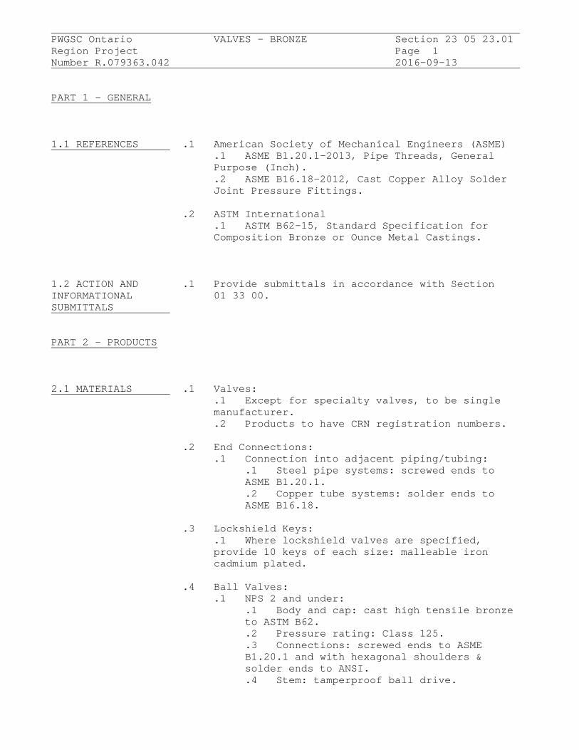
PWGSC Ontario VALVES - BRONZE Section 23 05 23.01
Region Project Page 1Number R.079363.042 2016-09-13
PART 1 - GENERAL
1.1 REFERENCES .1 American Society of Mechanical Engineers (ASME).1 ASME B1.20.1-2013, Pipe Threads, GeneralPurpose (Inch)..2 ASME B16.18-2012, Cast Copper Alloy SolderJoint Pressure Fittings.
.2 ASTM International.1 ASTM B62-15, Standard Specification forComposition Bronze or Ounce Metal Castings.
1.2 ACTION AND .1 Provide submittals in accordance with SectionINFORMATIONAL 01 33 00.SUBMITTALS
PART 2 - PRODUCTS
2.1 MATERIALS .1 Valves:.1 Except for specialty valves, to be singlemanufacturer..2 Products to have CRN registration numbers.
.2 End Connections:.1 Connection into adjacent piping/tubing:
.1 Steel pipe systems: screwed ends toASME B1.20.1..2 Copper tube systems: solder ends toASME B16.18.
.3 Lockshield Keys:.1 Where lockshield valves are specified,provide 10 keys of each size: malleable ironcadmium plated.
.4 Ball Valves:.1 NPS 2 and under:
.1 Body and cap: cast high tensile bronzeto ASTM B62..2 Pressure rating: Class 125..3 Connections: screwed ends to ASMEB1.20.1 and with hexagonal shoulders &solder ends to ANSI..4 Stem: tamperproof ball drive.

PWGSC Ontario VALVES - BRONZE Section 23 05 23.01
Region Project Page 2Number R.079363.042 2016-09-13
2.1 MATERIALS .4 (Cont'd) (Cont'd) .1 (Cont'd)
.5 Stem packing nut: external to body.
.6 Ball and seat: replaceable hard chromesolid ball and Teflon seats..7 Stem seal: TFE with external packingnut..8 Operator: removable lever handle.
PART 3 - EXECUTION
3.1 INSTALLATION .1 Install rising stem valves in upright positionwith stem above horizontal.
.2 Remove internal parts before soldering.
.3 Install valves with unions at each piece ofequipment arranged to allow servicing,maintenance, and equipment removal.
END OF SECTION

PWGSC Ontario HANGERS AND SUPPORTS FOR Section 23 05 29
Region Project HVAC PIPING AND EQUIPMENT Page 1Number R.079363.042 2016-09-13
PART 1 - GENERAL
1.1 RELATED .1 Section 05 12 23REQUIREMENTS
1.2 REFERENCES .1 American Society of Mechanical Engineers (ASME).1 ASME B31.1-2014, Power Piping.
.2 ASTM International.1 ASTM A125-96(2013)e1, StandardSpecification for Steel Springs, Helical,Heat-Treated..2 ASTM A307-14, Standard Specification forCarbon Steel Bolts and Studs, 60,000 PSI TensileStrength..3 ASTM A563-15, Standard Specification forCarbon and Alloy Steel Nuts.
.3 Manufacturer's Standardization Society of theValves and Fittings Industry (MSS).1 MSS SP-58-2009, Pipe Hangers and Supports -Materials, Design, Manufacture, Selection andInstallation Practices.
PART 2 - PRODUCTS
2.1 SYSTEM .1 Design Requirements:DESCRIPTION .1 Construct pipe hanger and support to
manufacturer's recommendations utilizingmanufacturer's regular production components,parts and assemblies..2 Base maximum load ratings on allowablestresses prescribed by ASME B31.1 or MSS SP-58..3 Ensure that supports, guides, anchors donot transmit excessive quantities of heat tobuilding structure..4 Design hangers and supports to supportsystems under conditions of operation, allowfree expansion and contraction, preventexcessive stresses from being introduced intopipework or connected equipment..5 Provide for vertical adjustments aftererection and during commissioning. Amount ofadjustment in accordance with MSS SP-58.

PWGSC Ontario HANGERS AND SUPPORTS FOR Section 23 05 29
Region Project HVAC PIPING AND EQUIPMENT Page 2Number R.079363.042 2016-09-13
2.2 GENERAL .1 Fabricate hangers, supports and sway braces inaccordance with MSS SP-58 and ASME B31.1.
.2 Use components for intended design purpose only.Do not use for rigging or erection purposes.
2.3 PIPE HANGERS .1 Finishes:.1 Pipe hangers and supports: galvanized aftermanufacture..2 Use electro-plating galvanizing process orhot dipped galvanizing process..3 Ensure steel hangers in contact with copperpiping are copper plated or epoxy coated.
.2 Upper attachment structural: suspension fromlower flange of I-Beam:.1 Cold piping NPS 2 maximum: malleable ironC-clamp with hardened steel cup point setscrew,locknut and carbon steel retaining clip.
.1 Rod: 9 mm UL listed ..2 Cold piping NPS 2 1/2 or greater, hotpiping: malleable iron beam clamp, eye rod, jawsand extension with carbon steel retaining clip,tie rod, nuts and washers, UL listed to MSSSP-58.
.3 Upper attachment structural: suspension fromupper flange of I-Beam:.1 Cold piping NPS 2 maximum: ductile irontop-of-beam C-clamp with hardened steel cuppoint setscrew, locknut and carbon steelretaining clip, UL listed to MSS SP-58..2 Cold piping NPS 2 1/2 or greater, hotpiping: malleable iron top-of-beam jaw-clampwith hooked rod, spring washer, plain washer andnut UL listed .
.4 Upper attachment to concrete:.1 Ceiling: carbon steel welded eye rod,clevis plate, clevis pin and cotters withweldless forged steel eye nut. Ensure eye 6 mmminimum greater than rod diameter..2 Concrete inserts: wedge shaped body withknockout protector plate UL listed to MSS SP-58.
.5 Hanger rods: threaded rod material to MSS SP 58:.1 Ensure that hanger rods are subject totensile loading only.

PWGSC Ontario HANGERS AND SUPPORTS FOR Section 23 05 29
Region Project HVAC PIPING AND EQUIPMENT Page 3Number R.079363.042 2016-09-13
2.3 PIPE HANGERS .5 (Cont'd) (Cont'd) .2 Provide linkages where lateral or axial
movement of pipework is anticipated..3 Do not use 22 mm or 28 mm rod.
.6 Pipe attachments: material to MSS SP-58:.1 Attachments for steel piping: carbon steelblack galvanized..2 Attachments for copper piping: copperplated black steel..3 Use insulation shields for hot pipework..4 Oversize pipe hangers and supports.
.7 Adjustable clevis: material to MSS SP 58 ULlisted, clevis bolt with nipple spacer andvertical adjustment nuts above and below clevis..1 Ensure "U" has hole in bottom for rivettingto insulation shields.
.8 Yoke style pipe roll: carbon steel yoke, rod andnuts with cast iron roll, to MSS SP-58.
.9 U-bolts: carbon steel to MSS SP-58 with 2 nutsat each end to ASTM A563..1 Finishes for steel pipework: black..2 Finishes for copper, glass, brass oraluminum pipework: black epoxy coated.
.10 Pipe rollers: cast iron roll and roll stand withcarbon steel rod to MSS SP-58.
2.4 RISER CLAMPS .1 Steel or cast iron pipe: black carbon steel toMSS SP-58, type 42, UL listed.
.2 Copper pipe: carbon steel copper plated to MSSSP-58, type 42.
.3 Bolts: to ASTM A307.
.4 Nuts: to ASTM A563.
2.5 INSULATION .1 Insulated cold piping:PROTECTION SHIELDS .1 64 kg/m3 density insulation plus insulation
protection shield to: MSS SP-58, galvanizedsheet carbon steel. Length designed for maximum3 m span.

PWGSC Ontario HANGERS AND SUPPORTS FOR Section 23 05 29
Region Project HVAC PIPING AND EQUIPMENT Page 4Number R.079363.042 2016-09-13
2.5 INSULATION .2 Insulated hot piping:PROTECTION SHIELDS .1 Curved plate 300 mm long, with edges turned (Cont'd) up, welded-in centre plate for pipe sizes NPS 12
and over, carbon steel to comply with MSS SP-58.
2.6 CONSTANT .1 Springs: alloy steel to ASTM A125, shot peened,SUPPORT SPRING magnetic particle inspected, with +/-5% springHANGERS rate tolerance, tested for free height, spring
rate, loaded height and provided with CertifiedMill Test Report (CMTR).
.2 Load adjustability: 10% minimum adjustabilityeach side of calibrated load. Adjustment withoutspecial tools. Adjustments not to affect travelcapabilities.
.3 Provide upper and lower factory set travelstops.
.4 Provide load adjustment scale for fieldadjustments.
.5 Total travel to be actual travel + 20%.Difference between total travel and actualtravel 25 mm minimum.
.6 Individually calibrated scales on each side ofsupport calibrated prior to shipment, completewith calibration record.
2.7 VARIABLE .1 Vertical movement: 13 mm minimum, 50 mm maximum,SUPPORT SPRING use single spring pre-compressed variable springHANGERS hangers.
.2 Vertical movement greater than 50 mm: use doublespring pre-compressed variable spring hangerwith 2 springs in series in single casing.
.3 Variable spring hanger complete with factorycalibrated travel stops. Provide certificate ofcalibration for each hanger.
.4 Steel alloy springs: to ASTM A125, shot peened,magnetic particle inspected, with +/-5 % springrate tolerance, tested for free height, springrate, loaded height and provided with CMTR.

PWGSC Ontario HANGERS AND SUPPORTS FOR Section 23 05 29
Region Project HVAC PIPING AND EQUIPMENT Page 5Number R.079363.042 2016-09-13
2.8 EQUIPMENT .1 Fabricate equipment supports not provided bySUPPORTS equipment manufacturer from structural grade
steel meeting requirements of Section 05 12 23.Submit calculations with shop drawings.
2.9 EQUIPMENT .1 Provide templates to ensure accurate location ofANCHOR BOLTS AND anchor bolts.TEMPLATES
PART 3 - EXECUTION
3.1 MANUFACTURER'S .1 Compliance: comply with manufacturer's writtenINSTRUCTIONS recommendations or specifications, including
product technical bulletins, handling, storageand installation instructions, and datasheet.
3.2 INSTALLATION .1 Install in accordance with:.1 Manufacturer's instructions andrecommendations.
.2 Vibration Control Devices:.1 Install on piping systems at pumps,boilers, chillers, cooling towers, and asindicated.
.3 Clamps on riser piping:.1 Support independent of connected horizontalpipework using riser clamps and riser clamp lugswelded to riser..2 Bolt-tightening torques to industrystandards..3 Steel pipes: install below coupling orshear lugs welded to pipe..4 Cast iron pipes: install below joint.
.4 Clevis plates:.1 Attach to concrete with 4 minimum concreteinserts, one at each corner.
.5 Provide supplementary structural steelwork wherestructural bearings do not exist or whereconcrete inserts are not in correct locations.
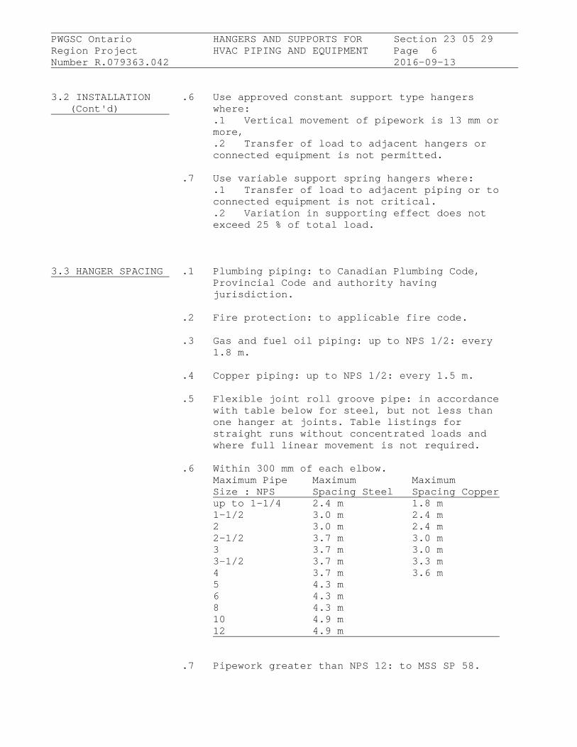
PWGSC Ontario HANGERS AND SUPPORTS FOR Section 23 05 29
Region Project HVAC PIPING AND EQUIPMENT Page 6Number R.079363.042 2016-09-13
3.2 INSTALLATION .6 Use approved constant support type hangers (Cont'd) where:
.1 Vertical movement of pipework is 13 mm ormore,.2 Transfer of load to adjacent hangers orconnected equipment is not permitted.
.7 Use variable support spring hangers where:.1 Transfer of load to adjacent piping or toconnected equipment is not critical..2 Variation in supporting effect does notexceed 25 % of total load.
3.3 HANGER SPACING .1 Plumbing piping: to Canadian Plumbing Code,Provincial Code and authority havingjurisdiction.
.2 Fire protection: to applicable fire code.
.3 Gas and fuel oil piping: up to NPS 1/2: every1.8 m.
.4 Copper piping: up to NPS 1/2: every 1.5 m.
.5 Flexible joint roll groove pipe: in accordancewith table below for steel, but not less thanone hanger at joints. Table listings forstraight runs without concentrated loads andwhere full linear movement is not required.
.6 Within 300 mm of each elbow.Maximum Pipe Maximum MaximumSize : NPS Spacing Steel Spacing Copperup to 1-1/4 2.4 m 1.8 m1-1/2 3.0 m 2.4 m2 3.0 m 2.4 m2-1/2 3.7 m 3.0 m3 3.7 m 3.0 m3-1/2 3.7 m 3.3 m4 3.7 m 3.6 m5 4.3 m6 4.3 m8 4.3 m10 4.9 m12 4.9 m
.7 Pipework greater than NPS 12: to MSS SP 58.

PWGSC Ontario HANGERS AND SUPPORTS FOR Section 23 05 29
Region Project HVAC PIPING AND EQUIPMENT Page 7Number R.079363.042 2016-09-13
3.4 HANGER .1 Install hanger so that rod is vertical underINSTALLATION operating conditions.
.2 Adjust hangers to equalize load.
.3 Support from structural members. Wherestructural bearing does not exist or inserts arenot in suitable locations, provide supplementarystructural steel members.
3.5 HORIZONTAL .1 Angularity of rod hanger resulting fromMOVEMENT horizontal movement of pipework from cold to hot
position not to exceed 4 degrees from vertical.
.2 Where horizontal pipe movement is less than13 mm, offset pipe hanger and support so thatrod hanger is vertical in the hot position.
3.6 FINAL .1 Adjust hangers and supports:ADJUSTMENT .1 sure that rod is vertical under operating
conditions..2 Equalize loads.
.2 Adjustable clevis:.1 Tighten hanger load nut securely to ensureproper hanger performance..2 Tighten upper nut after adjustment.
.3 C-clamps:.1 Follow manufacturer's recommended writteninstructions and torque values when tighteningC-clamps to bottom flange of beam.
.4 Beam clamps:.1 Hammer jaw firmly against underside ofbeam.
END OF SECTION

PWGSC Ontario MECHANICAL IDENTIFICATION Sect 23 05 53.01
Region Project Page 1Number R.079363.042 2016-09-13
PART 1 - GENERAL
1.1 REFERENCES .1 Canadian Standards Association (CSA).
.2 Canadian General Standards Board (CGSB).1 CAN/CGSB-24.3-92, Identification of PipingSystems.
.3 National Fire Protection Association (NFPA).1 NFPA (Fire) 13, Standard for theInstallation of Sprinkler Systems, 2013 Edition.
PART 2 - PRODUCTS
2.1 MANUFACTURER'S .1 Metal or plastic laminate nameplate mechanicallyEQUIPMENT fastened to each piece of equipment byNAMEPLATES manufacturer.
.2 Lettering and numbers raised or recessed.
.3 Information to include, as appropriate:.1 Equipment: manufacturer's name, model,size, serial number, capacity..2 Motor: voltage, Hz, phase, power factor,duty, frame size.
2.2 EXISTING .1 Apply existing identification system to newIDENTIFICATION work.SYSTEMS
.2 Where existing identification system does notcover for new work, use identification systemspecified this section.
.3 Before starting work, obtain written approval ofidentification system from DepartmentalRepresentative.
2.3 PIPING SYSTEMS .1 Identification:GOVERNED BY CODES .1 Sprinklers: to NFPA (Fire) 13.

PWGSC Ontario MECHANICAL IDENTIFICATION Sect 23 05 53.01
Region Project Page 2Number R.079363.042 2016-09-13
2.4 IDENTIFICATION .1 Identify contents by background colour marking,OF PIPING SYSTEMS pictogram (as necessary), legend; direction of
flow by arrows. To CAN/CGSB-24.3 except wherespecified otherwise.
.2 Pictograms:.1 Where required: Workplace HazardousMaterials Information System (WHMIS)regulations.
.3 Legend:.1 Block capitals to sizes and colours listedin CAN/CGSB-24.3.
.4 Arrows showing direction of flow:.1 Outside diameter of pipe or insulation lessthan 75 mm: 100 mm long x 50 mm high..2 Outside diameter of pipe or insulation75 mm and greater: 150 mm long x 50 mm high..3 Use double-headed arrows where flow isreversible.
.5 Extent of background colour marking:.1 To full circumference of pipe orinsulation..2 Length to accommodate pictogram, fulllength of legend and arrows.
.6 Materials for background colour marking, legend,arrows:.1 Pipes and tubing 20 mm and smaller:waterproof and heat-resistant pressure sensitiveplastic marker tags..2 Other pipes: pressure sensitive vinyl withprotective overcoating, waterproof contactadhesive undercoating, suitable for ambient of100% RH and continuous operating temperature of150 degrees C and intermittent temperature of200 degrees C.
.7 Colours and Legends:.1 Where not listed, obtain direction fromDepartmental Representative..2 Colours for legends, arrows: to followingtable:
Background colour: Legend, arrows: Yellow BLACK Green WHITE Red WHITE

PWGSC Ontario MECHANICAL IDENTIFICATION Sect 23 05 53.01
Region Project Page 3Number R.079363.042 2016-09-13
2.4 IDENTIFICATION .7 (Cont'd)OF PIPING SYSTEMS .3 Background colour marking and legends for (Cont'd) piping systems:
Contents Background colour Legend marking Hot water heating supply Yellow HEATING SUPPLY Hot water heating return Yellow HEATING RETURN Domestic hot water supply Green DOM. HW SUPPLY Dom. HWS recirculation Green DOM. HW CIRC Domestic cold water supply Green DOM. CWS source) Sanitary Green SAN Plumbing vent Green SAN.VENT
2.5 IDENTIFICATION .1 50 mm high stencilled letters and directionalDUCTWORK SYSTEMS arrows 150 mm long x 50 mm high.
.2 Colours: back, or co-ordinated with base colourto ensure strong contrast.
2.6 VALVES, .1 Brass tags with 12 mm stamped identificationCONTROLLERS data filled with black paint.
.2 Include flow diagrams for each system, ofapproved size, showing charts and schedules withidentification of each tagged item, valve type,service, function, normal position, location oftagged item.
2.7 LANGUAGE .1 Identification in English.
PART 3 - EXECUTION
3.1 MANUFACTURER'S .1 Compliance: comply with manufacturer's writtenINSTRUCTIONS recommendations or specifications, including
product technical bulletins, handling, storageand installation instructions, and datasheet.

PWGSC Ontario MECHANICAL IDENTIFICATION Sect 23 05 53.01
Region Project Page 4Number R.079363.042 2016-09-13
3.2 INSTALLATION .1 Perform work in accordance with CAN/CGSB-24.3except as specified otherwise.
.2 Provide ULC and/or CSA registration plates asrequired by respective agency.
.3 Identify systems, equipment to conform to PWGSCPMSS.
3.3 NAMEPLATES .1 Locations:.1 In conspicuous location to facilitate easyreading and identification from operating floor.
.2 Standoffs:.1 Provide for nameplates on hot and/orinsulated surfaces.
.3 Protection:.1 Do not paint, insulate or cover.
3.4 LOCATION OF .1 On long straight runs in open areas in boilerIDENTIFICATION ON rooms, equipment rooms, galleries, tunnels: atPIPING AND DUCTWORK not more than 17 m intervals and more frequentlySYSTEMS if required to ensure that at least one is
visible from any one viewpoint in operatingareas and walking aisles.
.2 Adjacent to each change in direction.
.3 At least once in each small room through whichpiping or ductwork passes.
.4 On both sides of visual obstruction or where runis difficult to follow.
.5 On both sides of separations such as walls,floors, partitions.
.6 Where system is installed in pipe chases,ceiling spaces, galleries, confined spaces, atentry and exit points, and at access openings.
.7 At beginning and end points of each run and ateach piece of equipment in run.
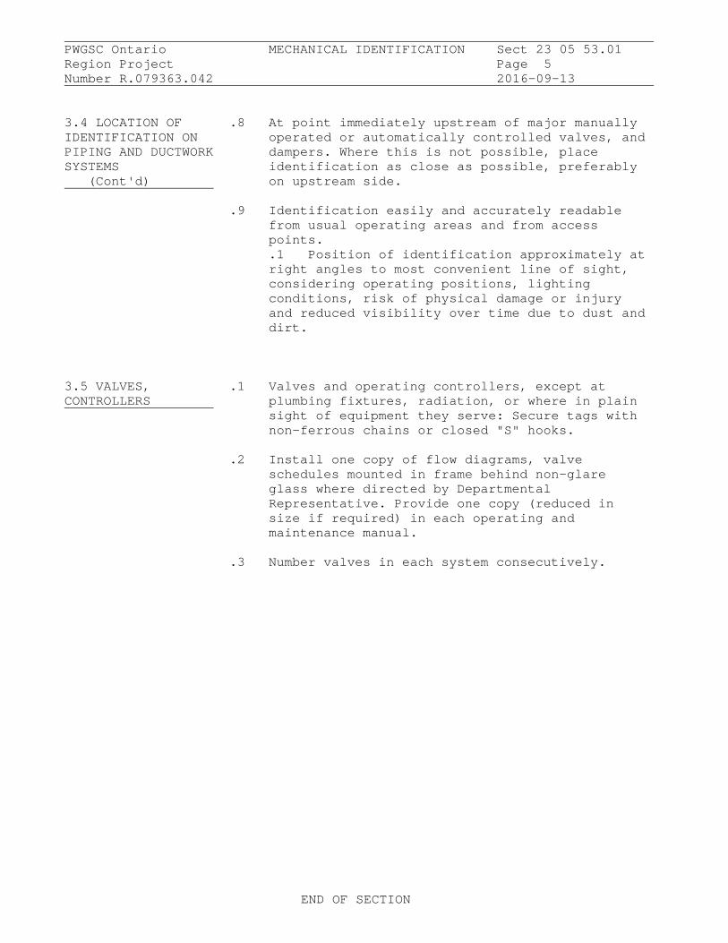
PWGSC Ontario MECHANICAL IDENTIFICATION Sect 23 05 53.01
Region Project Page 5Number R.079363.042 2016-09-13
3.4 LOCATION OF .8 At point immediately upstream of major manuallyIDENTIFICATION ON operated or automatically controlled valves, andPIPING AND DUCTWORK dampers. Where this is not possible, placeSYSTEMS identification as close as possible, preferably (Cont'd) on upstream side.
.9 Identification easily and accurately readablefrom usual operating areas and from accesspoints..1 Position of identification approximately atright angles to most convenient line of sight,considering operating positions, lightingconditions, risk of physical damage or injuryand reduced visibility over time due to dust anddirt.
3.5 VALVES, .1 Valves and operating controllers, except atCONTROLLERS plumbing fixtures, radiation, or where in plain
sight of equipment they serve: Secure tags withnon-ferrous chains or closed "S" hooks.
.2 Install one copy of flow diagrams, valveschedules mounted in frame behind non-glareglass where directed by DepartmentalRepresentative. Provide one copy (reduced insize if required) in each operating andmaintenance manual.
.3 Number valves in each system consecutively.
END OF SECTION

PWGSC Ontario DUCT INSULATION Section 23 07 13
Region Project Page 1Number R.079363.042 2016-09-13
PART 1 - GENERAL
1.1 RELATED .1 Section 23 05 29.REQUIREMENTS
1.2 REFERENCES .1 Definitions:.1 For purposes of this section:
.1 "CONCEALED" - insulated mechanicalservices and equipment in suspendedceilings and non-accessible chases andfurred-in spaces..2 "EXPOSED" - means "not concealed" aspreviouslydefined..3 Insulation systems - insulationmaterial, fasteners, jackets, and otheraccessories.
.2 TIAC Codes:.1 CRD: Code Round Ductwork,.2 CRF: Code Rectangular Finish.
.2 Reference Standards:.1 ASTM International Inc.
.1 ASTM C335-10e1, Standard Test Methodfor Steady State Heat Transfer Propertiesof Pipe Insulation..2 ASTM C449-07(2013), StandardSpecification for Mineral Fiber-Hydraulic-Setting Thermal Insulating and FinishingCement..3 ASTM C553-13, Standard Specificationfor Mineral Fiber Blanket ThermalInsulation for Commercial and IndustrialApplications..4 ASTM C612-14, Standard Specificationfor Mineral Fiber Block and Board ThermalInsulation..5 ASTM C921-09(2014), Standard Practicefor Determining the Properties of JacketingMaterials for Thermal Insulation.
.2 Canadian General Standards Board (CGSB).1 CGSB 51-GP-52Ma-89, Vapour Barrier,Jacket and Facing Material for Pipe, Ductand Equipment Thermal Insulation.
.3 Thermal Insulation Association of Canada(TIAC): National Insulation Standards (2005)..4 Underwriters Laboratories of Canada (ULC)
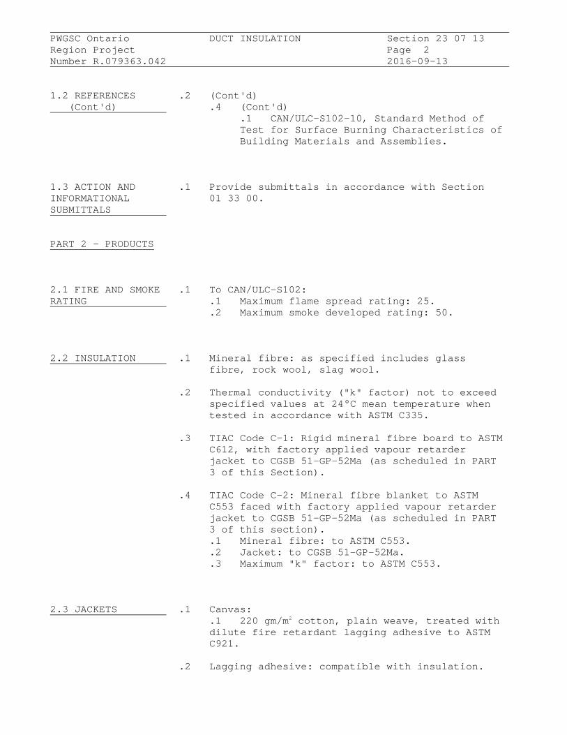
PWGSC Ontario DUCT INSULATION Section 23 07 13
Region Project Page 2Number R.079363.042 2016-09-13
1.2 REFERENCES .2 (Cont'd) (Cont'd) .4 (Cont'd)
.1 CAN/ULC-S102-10, Standard Method ofTest for Surface Burning Characteristics ofBuilding Materials and Assemblies.
1.3 ACTION AND .1 Provide submittals in accordance with SectionINFORMATIONAL 01 33 00.SUBMITTALS
PART 2 - PRODUCTS
2.1 FIRE AND SMOKE .1 To CAN/ULC-S102:RATING .1 Maximum flame spread rating: 25.
.2 Maximum smoke developed rating: 50.
2.2 INSULATION .1 Mineral fibre: as specified includes glassfibre, rock wool, slag wool.
.2 Thermal conductivity ("k" factor) not to exceedspecified values at 24°C mean temperature whentested in accordance with ASTM C335.
.3 TIAC Code C-1: Rigid mineral fibre board to ASTMC612, with factory applied vapour retarderjacket to CGSB 51-GP-52Ma (as scheduled in PART3 of this Section).
.4 TIAC Code C-2: Mineral fibre blanket to ASTMC553 faced with factory applied vapour retarderjacket to CGSB 51-GP-52Ma (as scheduled in PART3 of this section)..1 Mineral fibre: to ASTM C553..2 Jacket: to CGSB 51-GP-52Ma..3 Maximum "k" factor: to ASTM C553.
2.3 JACKETS .1 Canvas:.1 220 gm/m2 cotton, plain weave, treated withdilute fire retardant lagging adhesive to ASTMC921.
.2 Lagging adhesive: compatible with insulation.

PWGSC Ontario DUCT INSULATION Section 23 07 13
Region Project Page 3Number R.079363.042 2016-09-13
2.4 ACCESSORIES .1 Vapour retarder lap adhesive:.1 Water based, fire retardant type,compatible with insulation.
.2 Indoor Vapour Retarder Finish:.1 Vinyl emulsion type acrylic, compatiblewith insulation.
.3 Insulating Cement: hydraulic setting on mineralwool, to ASTM C449.
.4 ULC Listed Canvas Jacket:.1 220 gm/m2 cotton, plain weave, treated withdilute fire retardant lagging adhesive to ASTMC921 untreated.
.5 Tape: self-adhesive, aluminum, reinforced, 50mm wide minimum.
.6 Contact adhesive: quick-setting
.7 Canvas adhesive: washable.
.8 Tie wire: 1.5 mm stainless steel.
.9 Banding: 12 mm wide, 0.5 mm thick stainlesssteel.
.10 Facing: 25 mm galvanized steel hexagonal wiremesh stitched on one face both of insulation .
.11 Fasteners: 4 mm diameter pins with 35 mmdiameter clips, length to suit thickness ofinsulation.
PART 3 - EXECUTION
3.1 APPLICATION .1 Manufacturer's Instructions: comply withmanufacturer's written recommendations,including product technical bulletins, handling,storage and installation instructions, anddatasheets.
3.2 INSTALLATION .1 Install in accordance with TIAC NationalStandards.
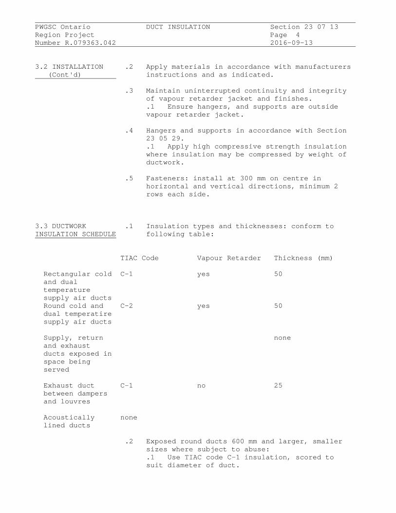
PWGSC Ontario DUCT INSULATION Section 23 07 13
Region Project Page 4Number R.079363.042 2016-09-13
3.2 INSTALLATION .2 Apply materials in accordance with manufacturers (Cont'd) instructions and as indicated.
.3 Maintain uninterrupted continuity and integrityof vapour retarder jacket and finishes..1 Ensure hangers, and supports are outsidevapour retarder jacket.
.4 Hangers and supports in accordance with Section23 05 29..1 Apply high compressive strength insulationwhere insulation may be compressed by weight ofductwork.
.5 Fasteners: install at 300 mm on centre inhorizontal and vertical directions, minimum 2rows each side.
3.3 DUCTWORK .1 Insulation types and thicknesses: conform toINSULATION SCHEDULE following table:
TIAC Code Vapour Retarder Thickness (mm)
Rectangular cold C-1 yes 50 and dual temperature supply air ducts Round cold and C-2 yes 50 dual temperatire supply air ducts
Supply, return none and exhaust ducts exposed in space being served
Exhaust duct C-1 no 25 between dampers and louvres
Acoustically none lined ducts
.2 Exposed round ducts 600 mm and larger, smallersizes where subject to abuse:.1 Use TIAC code C-1 insulation, scored tosuit diameter of duct.

PWGSC Ontario DUCT INSULATION Section 23 07 13
Region Project Page 5Number R.079363.042 2016-09-13
3.3 DUCTWORK .2 (Cont'd)INSULATION SCHEDULE .1 (Cont'd) (Cont'd) .1 Finishes: conform to following table:
TIAC CodeRectangular Round
Indoor, concealed none none
Indoor, exposed within CRF/1 CRD/2 mechanical room
Indoor, exposed CRF/2 CRD/3 elsewhere
END OF SECTION
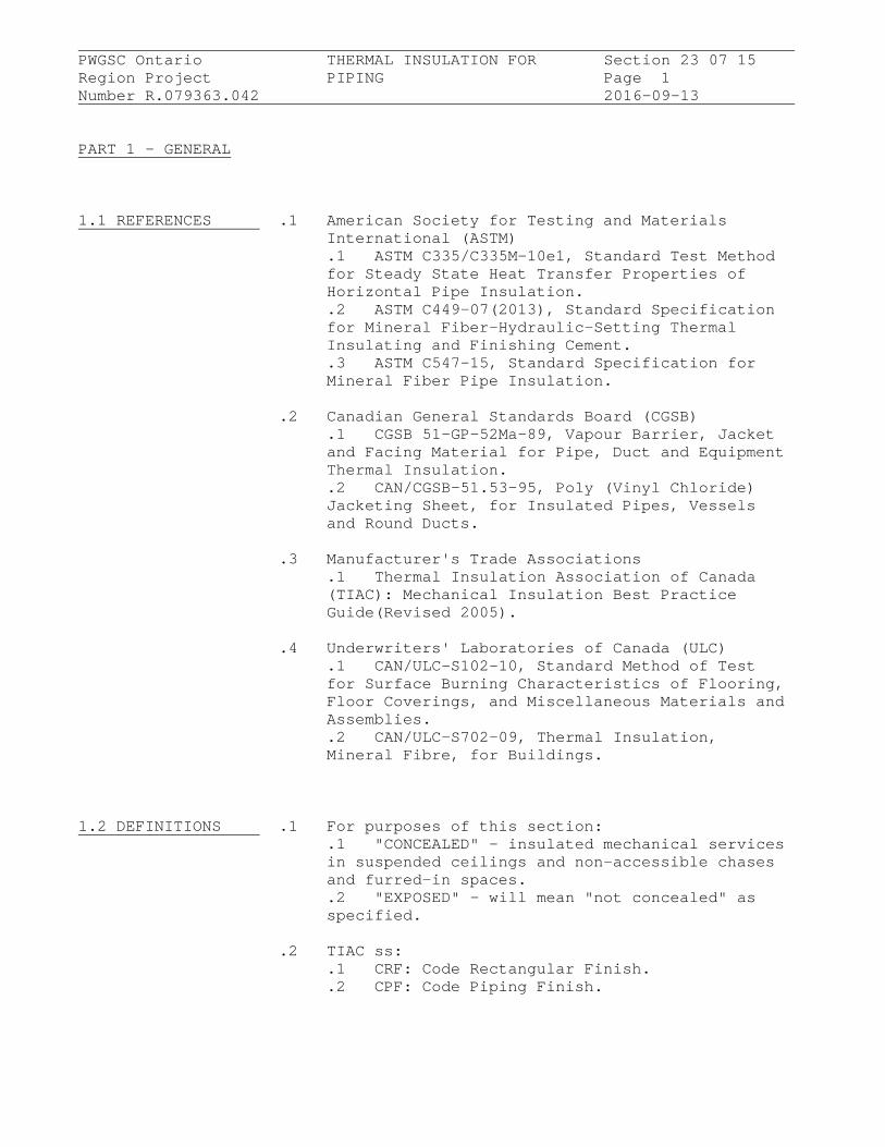
PWGSC Ontario THERMAL INSULATION FOR Section 23 07 15
Region Project PIPING Page 1Number R.079363.042 2016-09-13
PART 1 - GENERAL
1.1 REFERENCES .1 American Society for Testing and MaterialsInternational (ASTM).1 ASTM C335/C335M-10e1, Standard Test Methodfor Steady State Heat Transfer Properties ofHorizontal Pipe Insulation..2 ASTM C449-07(2013), Standard Specificationfor Mineral Fiber-Hydraulic-Setting ThermalInsulating and Finishing Cement..3 ASTM C547-15, Standard Specification forMineral Fiber Pipe Insulation.
.2 Canadian General Standards Board (CGSB).1 CGSB 51-GP-52Ma-89, Vapour Barrier, Jacketand Facing Material for Pipe, Duct and EquipmentThermal Insulation..2 CAN/CGSB-51.53-95, Poly (Vinyl Chloride)Jacketing Sheet, for Insulated Pipes, Vesselsand Round Ducts.
.3 Manufacturer's Trade Associations.1 Thermal Insulation Association of Canada(TIAC): Mechanical Insulation Best PracticeGuide(Revised 2005).
.4 Underwriters' Laboratories of Canada (ULC).1 CAN/ULC-S102-10, Standard Method of Testfor Surface Burning Characteristics of Flooring,Floor Coverings, and Miscellaneous Materials andAssemblies..2 CAN/ULC-S702-09, Thermal Insulation,Mineral Fibre, for Buildings.
1.2 DEFINITIONS .1 For purposes of this section:.1 "CONCEALED" - insulated mechanical servicesin suspended ceilings and non-accessible chasesand furred-in spaces..2 "EXPOSED" - will mean "not concealed" asspecified.
.2 TIAC ss:.1 CRF: Code Rectangular Finish..2 CPF: Code Piping Finish.
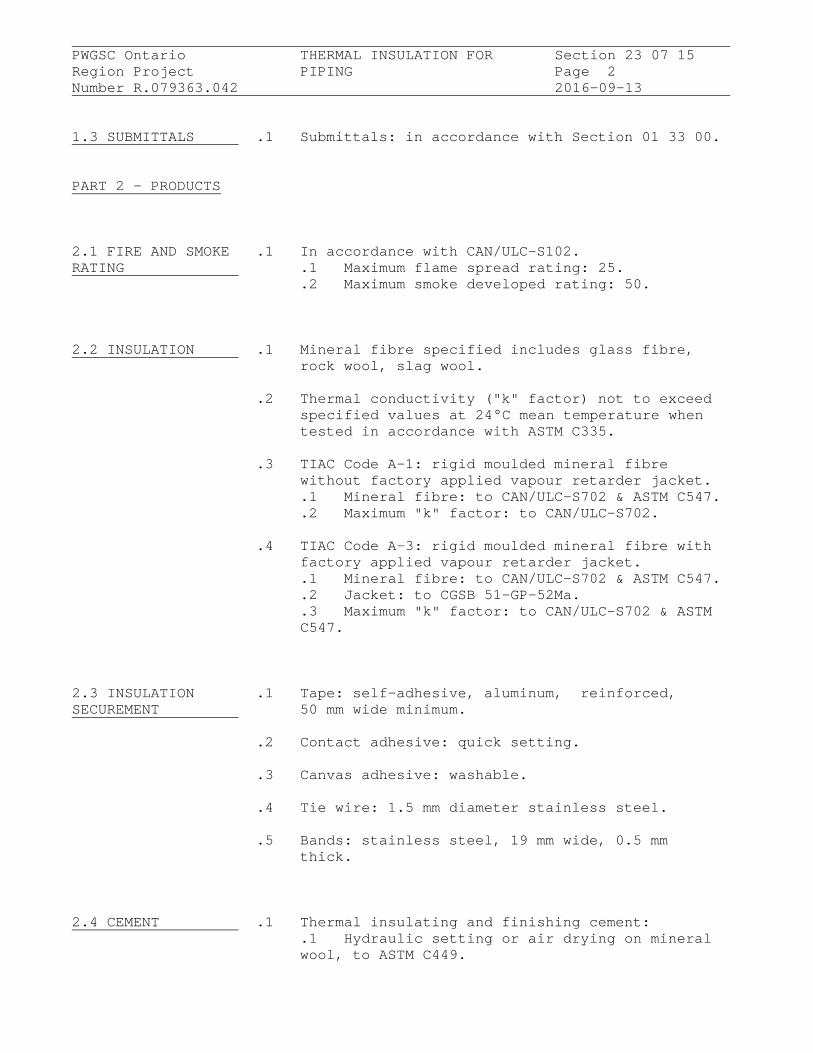
PWGSC Ontario THERMAL INSULATION FOR Section 23 07 15
Region Project PIPING Page 2Number R.079363.042 2016-09-13
1.3 SUBMITTALS .1 Submittals: in accordance with Section 01 33 00.
PART 2 - PRODUCTS
2.1 FIRE AND SMOKE .1 In accordance with CAN/ULC-S102.RATING .1 Maximum flame spread rating: 25.
.2 Maximum smoke developed rating: 50.
2.2 INSULATION .1 Mineral fibre specified includes glass fibre,rock wool, slag wool.
.2 Thermal conductivity ("k" factor) not to exceedspecified values at 24°C mean temperature whentested in accordance with ASTM C335.
.3 TIAC Code A-1: rigid moulded mineral fibrewithout factory applied vapour retarder jacket..1 Mineral fibre: to CAN/ULC-S702 & ASTM C547..2 Maximum "k" factor: to CAN/ULC-S702.
.4 TIAC Code A-3: rigid moulded mineral fibre withfactory applied vapour retarder jacket..1 Mineral fibre: to CAN/ULC-S702 & ASTM C547..2 Jacket: to CGSB 51-GP-52Ma..3 Maximum "k" factor: to CAN/ULC-S702 & ASTMC547.
2.3 INSULATION .1 Tape: self-adhesive, aluminum, reinforced,SECUREMENT 50 mm wide minimum.
.2 Contact adhesive: quick setting.
.3 Canvas adhesive: washable.
.4 Tie wire: 1.5 mm diameter stainless steel.
.5 Bands: stainless steel, 19 mm wide, 0.5 mmthick.
2.4 CEMENT .1 Thermal insulating and finishing cement:.1 Hydraulic setting or air drying on mineralwool, to ASTM C449.

PWGSC Ontario THERMAL INSULATION FOR Section 23 07 15
Region Project PIPING Page 3Number R.079363.042 2016-09-13
2.5 VAPOUR RETARDER .1 Water based, fire retardant type, compatibleLAP ADHESIVE with insulation.
2.6 INDOOR VAPOUR .1 Vinyl emulsion type acrylic, compatible withRETARDER FINISH insulation.
2.7 JACKETS .1 Polyvinyl Chloride (PVC):.1 One-piece moulded type and sheet toCAN/CGSB-51.53 with pre-formed shapes asrequired..2 Colours: white unless otherwise noted..3 Minimum service temperatures: -20 degreesC..4 Maximum service temperature: 65 degrees C..5 Moisture vapour transmission: 0.02 perm..6 Thickness: 0.015 mm..7 Fastenings:
.1 Use solvent weld adhesive compatiblewith insulation to seal laps and joints..2 Tacks..3 Pressure sensitive vinyl tape ofmatching colour.
PART 3 - EXECUTION
3.1 MANUFACTURER'S .1 Compliance: comply with manufacturer's writtenINSTRUCTIONS recommendations or specifications, including
product technical bulletins, handling, storageand installation instructions, and datasheet.
3.2 PRE- .1 Pressure testing of piping systems and adjacentINSTALLATION equipment to be complete, witnessed andREQUIREMENT certified.
.2 Surfaces clean, dry, free from foreign material.
3.3 INSTALLATION .1 Install in accordance with TIAC NationalStandards.
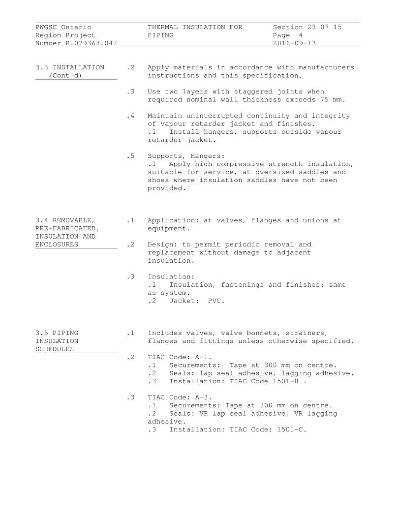
PWGSC Ontario THERMAL INSULATION FOR Section 23 07 15
Region Project PIPING Page 4Number R.079363.042 2016-09-13
3.3 INSTALLATION .2 Apply materials in accordance with manufacturers (Cont'd) instructions and this specification.
.3 Use two layers with staggered joints whenrequired nominal wall thickness exceeds 75 mm.
.4 Maintain uninterrupted continuity and integrityof vapour retarder jacket and finishes..1 Install hangers, supports outside vapourretarder jacket.
.5 Supports, Hangers:.1 Apply high compressive strength insulation,suitable for service, at oversized saddles andshoes where insulation saddles have not beenprovided.
3.4 REMOVABLE, .1 Application: at valves, flanges and unions atPRE-FABRICATED, equipment.INSULATION ANDENCLOSURES .2 Design: to permit periodic removal and
replacement without damage to adjacentinsulation.
.3 Insulation:.1 Insulation, fastenings and finishes: sameas system..2 Jacket: PVC.
3.5 PIPING .1 Includes valves, valve bonnets, strainers,INSULATION flanges and fittings unless otherwise specified.SCHEDULES
.2 TIAC Code: A-1..1 Securements: Tape at 300 mm on centre..2 Seals: lap seal adhesive, lagging adhesive..3 Installation: TIAC Code 1501-H .
.3 TIAC Code: A-3..1 Securements: Tape at 300 mm on centre..2 Seals: VR lap seal adhesive, VR laggingadhesive..3 Installation: TIAC Code: 1501-C.

PWGSC Ontario THERMAL INSULATION FOR Section 23 07 15
Region Project PIPING Page 5Number R.079363.042 2016-09-13
3.5 PIPING .4 Thickness of insulation as listed in followingINSULATION table.SCHEDULES .1 Do not insulate exposed runouts to plumbing (Cont'd) fixtures, chrome plated piping, valves,
fittings.
Applic Temp TIAC Pipe sizes (NPS) and insulation thickness ation degrees code (mm) C Run to 1 1-1/4 2-1/2 5 to 6 8 & out to 2 to 4 over
Hot 60 - A-1 25 38 38 38 38 38 Water 94 Heating
Domestic A-1 25 25 25 38 38 38 HWS
Domestic A-3 25 25 25 25 25 25 CWS
.5 Finishes:.1 Exposed indoors: PVC jacket..2 Exposed in mechanical rooms: PVC jacket..3 Concealed, indoors: canvas on valves,fittings. No further finish.
END OF SECTION
PWGSC Ontario PNEUMATIC CONTROL SYSTEM Section 23 09 43
Region Project FOR HVAC Page 1Number R.079363.042 2016-09-13
PART 1 - GENERAL
1.1 RELATED .1 Section 23 05 53.01.REQUIREMENTS
.2 Section 23 33 16.
1.2 ACTION AND .1 Submit in accordance with Section 01 33 00.INFORMATIONALSUBMITTALS
PART 2 - PRODUCTS
2.1 VALVES .1 Pressure rating: as indicated.
.2 Valve operators: spring return for "fail safe"in normally open position.
.3 Water valves:.1 Two-way: equal percentage, quick openingcharacteristics.
2.2 DAMPERS .1 Smoke type dampers are specified in Section23 33 16.
2.3 IDENTIFICATION .1 Provide in accordance with Section 23 05 53.01.
2.4 CONTROL AIR .1 Plastic: flame retardant PVC tubing with minimumTUBING burst gauge pressure of 1.4 MPa at 80 degrees C.
PART 3 - EXECUTION
3.1 MANUFACTURER'S .1 Compliance: comply with manufacturer's writtenINSTRUCTIONS recommendations or specifications, including
product technical bulletins, handling, storageand installation instructions, and datasheet.
END OF SECTION

PWGSC Ontario METAL DUCTS - LOW Section 23 31 13.01
Region Project PRESSURE TO 500 PA Page 1Number R.079363.042 2016-09-13
PART 1 - GENERAL
1.1 RELATED Section 23 05 94 .1 REQUIREMENTS
1.2 REFERENCES .1 ASTM International.1 ASTM A653/A653M-15, Standard Specificationfor Steel Sheet, Zinc Coated (Galvanized) orZinc-Iron Alloy Coated (Galvannealed) by theHot-Dip Process.
.2 National Fire Protection Association (NFPA).1 NFPA (Fire) 90A, Standard for theInstallation of Air-Conditioning and VentilatingSystems, 2015 Edition..2 NFPA (Fire) 90B, Standard for theInstallation 90B-12, Standard for theInstallation of Warm Air Heating andAir-Conditioning Systems, 2015 Edition.
.3 Sheet Metal and Air Conditioning Contractors'National Association (SMACNA).1 SMACNA HVAC Duct Construction Standards -Metal and Flexible, 2013..2 SMACNA HVAC Air Duct Leakage Test Manual,2012.
PART 2 - PRODUCTS
2.1 SEAL .1 Classification as follows:CLASSIFICATION
Maximum Pressure PA SMACNA Seal Class500 A250 A125 A
.2 Seal classification:.1 Class A: longitudinal seams, transversejoints, duct wall penetrations and connectionsmade airtight with sealant and tape.
PWGSC Ontario METAL DUCTS - LOW Section 23 31 13.01
Region Project PRESSURE TO 500 PA Page 2Number R.079363.042 2016-09-13
2.2 SEALANT .1 Sealant: oil resistant, , polymer type flameresistant duct sealant. Temperature range ofminus 30 degrees C to plus 93 degrees C.
2.3 DUCT LEAKAGE .1 In accordance with SMACNA HVAC Air Duct LeakageTest Manual.
2.4 FITTINGS .1 Fabrication: to SMACNA.
.2 Radiused elbows:.1 Rectangular: standard radius centrelineradius: 1.5 times width of duct..2 Round: 1.5 times diameter.
.3 Mitred elbows, rectangular:.1 To 400 mm: with single thickness turningvanes..2 Over 400 mm: with double thickness turningvanes.
.4 Branches:.1 Rectangular main and branch: with 45degrees entry on branch..2 Round main and branch: enter main duct at45 degrees with conical connection..3 Provide volume control damper in branchduct near connection to main duct.
.5 Transitions:.1 Diverging: 20 degrees maximum includedangle..2 Converging: 30 degrees maximum includedangle.
.6 Offsets:.1 Full radiused elbows .
.7 Obstruction deflectors: maintain fullcross-sectional area..1 Maximum included angles: as fortransitions.
2.5 FIRE STOPPING .1 Retaining angles around duct, on both sides offire separation.

PWGSC Ontario METAL DUCTS - LOW Section 23 31 13.01
Region Project PRESSURE TO 500 PA Page 3Number R.079363.042 2016-09-13
2.5 FIRE STOPPING .2 Fire stopping material and installation must not (Cont'd) distort duct.
2.6 GALVANIZED .1 Lock forming quality: to ASTM A653/A653M, Z90STEEL zinc coating.
.2 Thickness, fabrication and reinforcement: toSMACNA.
.3 Joints: to SMACNA.
2.7 HANGERS AND .1 Hangers and Supports: in accordance with SectionSUPPORTS 23 05 29.
.1 Strap hangers: of same material as duct butnext sheet metal thickness heavier than duct.
.1 Maximum size duct supported by straphanger: 500.
.2 Hanger configuration: to SMACNA.
.3 Hangers: black steel angle with black steelrods to SMACNA and following table:
Duct Size Angle Size Rod Size(mm) (mm) (mm)up to 750 25 x 25 x 3 6751 to 1050 40 x 40 x 3 61051 to 1500 40 x 40 x 3 101501 to 2100 50 x 50 x 3 102101 to 2400 50 x 50 x 5 102401 and over 50 x 50 x 6 10.4 Upper hanger attachments:
.1 For concrete: manufactured concreteinserts..2 For steel joist:manufactured joistclamp or steel plate washer..3 For steel beams: manufactured beamclamps:
PART 3 - EXECUTION
3.1 GENERAL .1 Do work in accordance with NFPA (Fire) 90A, NFPA(Fire) 90B and SMACNA.
PWGSC Ontario METAL DUCTS - LOW Section 23 31 13.01
Region Project PRESSURE TO 500 PA Page 4Number R.079363.042 2016-09-13
3.1 GENERAL .2 Do not break continuity of insulation vapour (Cont'd) barrier with hangers or rods.
.1 Insulate strap hangers 100 mm beyondinsulated duct. Ensure diffuser is fully seated.
.3 Support risers in accordance with SMACNA asindicated.
.4 Install breakaway joints in ductwork on sides offire separation.
.5 Install proprietary manufactured flanged ductjoints in accordance with manufacturer'sinstructions.
.6 Manufacture duct in lengths and diameter toaccommodate installation of acoustic ductlining.
3.2 HANGERS .1 Strap hangers: install in accordance withSMACNA.
.2 Angle hangers: complete with locking nuts andwashers.
.3 Hanger spacing: in accordance with SMACNA and asfollows:
Duct Size Spacing(mm) (mm)to 1500 30001501 and over 2500
3.3 SEALING .1 Apply sealant in accordance with SMACNA and tomanufacturer's recommendations.
3.4 LEAKAGE TESTS .1 Refer to Section 23 05 94.
.2 In accordance with SMACNA HVAC Duct Leakage TestManual.
.3 Do leakage tests in sections.
.4 Make trial leakage tests as instructed todemonstrate workmanship.

PWGSC Ontario METAL DUCTS - LOW Section 23 31 13.01
Region Project PRESSURE TO 500 PA Page 5Number R.079363.042 2016-09-13
3.4 LEAKAGE TESTS .5 Do not install additional ductwork until trial (Cont'd) test has been passed.
.6 Test section minimum of 30 m long with not lessthan three branch takeoffs and two 90 degreeselbows.
.7 Complete test before performance insulation orconcealment Work.
3.5 CLEANING .1 Progress Cleaning: clean in accordance withSection 01 74 11..1 Leave Work area clean at end of each day.
.2 Final Cleaning: upon completion remove surplusmaterials, rubbish, tools and equipment inaccordance with Section 01 74 11.
.3 Waste Management: separate waste materials forreuse and recycling in accordance with Section01 74 20 ..1 Remove recycling containers and bins fromsite and dispose of materials at appropriatefacility.
END OF SECTION
PWGSC Ontario AIR DUCT ACCESSORIES Section 23 33 00
Region Project Page 1Number R.079363.042 2016-09-13
PART 1 - GENERAL
1.1 REFERENCES .1 Sheet Metal and Air Conditioning Contractors'National Association (SMACNA).1 SMACNA - HVAC Duct Construction Standards -Metal and Flexible, 2005.
PART 2 - PRODUCTS
2.1 GENERAL .1 Manufacture in accordance with SMACNA - HVACDuct Construction Standards.
2.2 FLEXIBLE .1 Frame: galvanized sheet metal frame 0.6 mm thickCONNECTIONS with fabric clenched by means of double locked
seams.
.2 Material:.1 Fire resistant, self extinguishing,neoprene coated glass fabric, temperature ratedat minus 40 degrees C to plus 90 degrees C,density of 1.3 kg/m2.
2.3 ACCESS DOORS IN .1 Non-Insulated Ducts: sandwich construction ofDUCTS same material as duct, one sheet metal thickness
heavier, minimum 0.6 mm thick complete withsheet metal angle frame.
.2 Insulated Ducts: sandwich construction of samematerial as duct, one sheet metal thicknessheavier, minimum 0.6 mm thick complete withsheet metal angle frame and 25 mm thick rigidglass fibre insulation.
.3 Gaskets: neoprene .
.4 Hardware:.1 Up to 300 x 300 mm: two sash locks completewith safety chain..2 301 to 450 mm: four sash locks completewith safety chain..3 451 to 1000 mm: piano hinge and minimum twosash locks.

PWGSC Ontario AIR DUCT ACCESSORIES Section 23 33 00
Region Project Page 2Number R.079363.042 2016-09-13
2.3 ACCESS DOORS IN .4 (Cont'd)DUCTS .4 Doors over 1000 mm: piano hinge and two (Cont'd) handles operable from both sides.
.5 Hold open devices.
2.4 TURNING VANES .1 Factory or shop fabricated single thickness anddouble thickness with trailing edge, torecommendations of SMACNA and as indicated.
PART 3 - EXECUTION
3.1 INSTALLATION .1 Access Doors and Viewing Panels:.1 Size:
.1 300 x 300 mm for servicing entry..2 Locations:
.1 Fire dampers.
.2 Control dampers.
.3 Devices requiring maintenance.
.4 Required by code.
.5 Reheat coils.
.6 Elsewhere as indicated.
.2 Turning Vanes:.1 Install in accordance with recommendationsof SMACNA and as indicated.
END OF SECTION

PWGSC Ontario DAMPERS - BALANCING Section 23 33 14
Region Project Page 1Number R.079363.042 2016-09-13
PART 1 - GENERAL
1.1 REFERENCES .1 Sheet Metal and Air Conditioning NationalAssociation (SMACNA).1 SMACNA HVAC Duct Construction Standards,Metal and Flexible-2013.
PART 2 - PRODUCTS
2.1 GENERAL .1 Manufacture to SMACNA standards.
2.2 SINGLE BLADE .1 Fabricate from same material as duct, but oneDAMPERS sheet metal thickness heavier. V-groove
stiffened.
.2 Size and configuration to recommendations ofSMACNA, except maximum height 100 mm.
.3 Locking quadrant with shaft extension toaccommodate insulation thickness.
.4 Inside and outside nylon end bearings.
.5 Channel frame of same material as adjacent duct,complete with angle stop.
2.3 MULTI-BLADED .1 Factory manufactured of material compatible withDAMPERS duct.
.2 Opposed blade: configuration, metal thicknessand construction to recommendations of SMACNA.
.3 Maximum blade height: 100 mm.
.4 Bearings: self-lubricating nylon.
.5 Linkage: shaft extension with locking quadrant.
.6 Channel frame of same material as adjacent duct,complete with angle stop.

PWGSC Ontario DAMPERS - BALANCING Section 23 33 14
Region Project Page 2Number R.079363.042 2016-09-13
PART 3 - EXECUTION
3.1 INSTALLATION .1 Install where indicated.
.2 Install in accordance with recommendations ofSMACNA and in accordance with manufacturer'sinstructions.
.3 Locate balancing dampers in each branch duct,for supply, return and exhaust systems.
.4 Runouts to registers and diffusers: installsingle blade damper located as close as possibleto main ducts.
.5 Dampers: vibration free.
.6 Ensure damper operators are observable andaccessible.
.7 Corrections and adjustments conducted byDepartmental Representative.
END OF SECTION

PWGSC Ontario DAMPERS - FIRE Section 23 33 16
Region Project Page 1Number R.079363.042 2016-09-13
PART 1 - GENERAL
1.1 REFERENCES .1 National Fire Protection Association (NFPA).1 NFPA (Fire) 90A, Standard for theInstallation of Air Conditioning and VentilatingSystems, 2015 Edition.
.2 Underwriters Laboratories of Canada (ULC).1 CAN/ULC-S112-10, Standard Test Method ofFire Test of Fire Damper Assemblies.
1.2 ACTION AND .1 Submit in accordance with Section 01 33 00.INFORMATIONALSUBMITTALS
PART 2 - PRODUCTS
2.1 FIRE DAMPERS .1 Fire dampers: arrangement Type B or C, listedand bear label of ULC, meet requirements of NFPA(Fire) 90A and authorities having jurisdiction.Fire damper assemblies fire tested in accordancewith CAN/ULC-S112.
.2 Mild steel, factory fabricated for fire ratingrequirement to maintain integrity of fire walland/or fire separation..1 Fire dampers: 1-1/2 hour fire rated unlessotherwise indicated.
.3 Top hinged: offset single damper, round orsquare; or interlocking type; sized to maintainfull duct cross section as indicated.
.4 Fusible link actuated, weighted to close andlock in closed position when released.
.5 40 x 40 x 3 mm retaining angle iron frame, onfull perimeter of fire damper, on both sides offire separation being pierced.
.6 Unless otherwise indicated, the installationdetails given in SMACNA Install Fire Damp HVACand in manufacturer's instructions for firedampers shall be followed.

PWGSC Ontario DAMPERS - FIRE Section 23 33 16
Region Project Page 2Number R.079363.042 2016-09-13
PART 3 - EXECUTION
3.1 INSTALLATION .1 Install in accordance with NFPA (Fire) 90A andin accordance with conditions of ULC listing.
.2 Maintain integrity of fire separation.
.3 After completion and prior to concealment obtainapprovals of complete installation fromauthority having jurisdiction.
.4 Install access door adjacent to each damper.
.5 Co-ordinate with installer of fire stopping.
.6 Ensure access doors/panels, fusible links,damper operators are easily observed andaccessible.
.7 Install break-away joints of approved design oneach side of fire separation.
END OF SECTION

PWGSC Ontario FLEXIBLE DUCTS Section 23 33 46
Region Project Page 1Number R.079363.042 2016-09-13
PART 1 - GENERAL
1.1 REFERENCES .1 National Fire Protection Association (NFPA).1 NFPA (Fire) 90A, Standard for theInstallation of Air-Conditioning and VentilatingSystems, 2015 Edition..2 NFPA (Fire) 90B, Standard for Installationof Warm Air Heating and Air-ConditioningSystems, 2015 Edition.
.2 Sheet Metal and Air-Conditioning Contractors'National Association (SMACNA).1 SMACNA HVAC Duct Construction Standards -Metal and Flexible, 2013..2 SMACNA IAQ Guideline for Occupied Buildingsunder Construction, 2012.
.3 Underwriters' Laboratories (UL).1 UL 181-2005, Standard for Factory-Made AirDucts and Air Connectors.
.4 Underwriters' Laboratories of Canada (ULC).1 CAN/ULC-S110-07, Standard Methods of Testsfor Air Ducts.
1.2 ACTION AND .1 Submit in accordance with Section 01 33 00.INFORMATIONALSUBMITTALS
PART 2 - PRODUCTS
2.1 GENERAL .1 Factory fabricated to CAN/ULC-S110.
.2 Pressure drop coefficients listed below arebased on relative sheet metal duct pressure dropcoefficient of 1.00.
.3 Flame spread rating not to exceed 25. Smokedeveloped rating not to exceed 50.

PWGSC Ontario FLEXIBLE DUCTS Section 23 33 46
Region Project Page 2Number R.079363.042 2016-09-13
2.2 METALLIC - .1 Spiral wound flexible aluminum with factoryINSULATED applied, 37 mm thick flexible glass fibre
thermal insulation with vapour barrier andreinforced mylar/neoprene laminate jacket, asindicated.
.2 Performance:.1 Factory tested to 2.5 kPa without leakage..2 Maximum relative pressure drop coefficient:3..3 Maximum length 1.5 m.
PART 3 - EXECUTION
3.1 DUCT .1 Install in accordance with: CAN/ULC-S110, ULINSTALLATION 181, NFPA (Fire) 90A, NFPA (Fire) 90B and
SMACNA.
END OF SECTION

PWGSC Ontario DUCT LINERS Section 23 33 53
Region Project Page 1Number R.079363.042 2016-09-13
PART 1 - GENERAL
1.1 REFERENCES .1 ASTM International.1 ASTM C423-09a, Standard Test Method forSound Absorption and Sound AbsorptionCoefficients by the Reverberation Room Method..2 ASTM C916-14, Standard Specification forAdhesives for Duct Thermal Insulation..3 ASTM C1071-12, Standard specification forFibrous Glass Duct Lining Insulation (Thermaland Sound Absorbing Material)..4 ASTM C1338-14, Standard Test Method forDetermining Fungi Resistance of InsulationMaterials and Facings..5 ASTM G21-15, Standard Practice forDetermining Resistance of Synthetic PolymericMaterials to Fungi.
.2 National Fire Protection Association (NFPA).1 NFPA (Fire) 90A, Standard for theInstallation of Air Conditioning and VentilatingSystems, 2015 Edition..2 NFPA (Fire) 90B, Standard for theInstallation of Warm Air Heating and AirConditioning Systems, 2015 Edition..
.3 Sheet Metal and Air Conditioning Contractor'sNational Association (SMACNA).1 SMACNA, HVAC Duct Construction Standards,Metal and Flexible-2013..2 SMACNA IAQ Guideline for Occupied BuildingsUnder Construction-2012.
.4 Underwriter's Laboratories of Canada (ULC).1 CAN/ULC-S102-10, Standard Method of Testfor Surface Burning Characteristics of BuildingMaterials and Assemblies.
PART 2 - PRODUCTS
2.1 DUCT LINER .1 General:.1 Mineral Fibre duct liner: air surfacecoated mat facing..2 Flame spread rating shall not exceed 25.Smoke development rating shall not exceed 50when tested in accordance with CAN/ULC-S102.

PWGSC Ontario DUCT LINERS Section 23 33 53
Region Project Page 2Number R.079363.042 2016-09-13
2.1 DUCT LINER .1 (Cont'd) (Cont'd) .3 Fungi resistance: to ASTM C1338 & ASTM G21.
.2 Rigid:.1 Use on flat surfaces where indicated..2 25 mm thick, to ASTM C1071 , fibrous glassrigid board duct liner..3 Density: 36 kg/m3 minimum..4 Thermal resistance to be minimum 0.76 (m2.degrees C)/W for 25 mm thickness when tested inaccordance with ASTM C177, at 24 degrees C meantemperature..5 Maximum velocity on faced air side: 20.3m/s.
2.2 ADHESIVE .1 Adhesive: to ASTM C916.
.2 Flame spread rating shall not exceed 25. Smokedevelopment rating shall not exceed 50.Temperature range minus 29 degrees C to plus 93degrees C.
.3 Water-based fire retardant type.
2.3 FASTENERS .1 Weld pins 2.0 mm diameter, length to suitthickness of insulation. Metal retaining clips,32 mm square.
2.4 JOINT TAPE .1 Poly-Vinyl treated open weave fiberglassmembrane 50 mm wide.
2.5 SEALER .1 Meet requirements of NFPA (Fire) 90A and NFPA(Fire) 90B.
.2 Flame spread rating shall not exceed 25. Smokedevelopment rating shall not exceed 50.Temperature range minus 68 degrees C to plus 93degrees C.

PWGSC Ontario DUCT LINERS Section 23 33 53
Region Project Page 3Number R.079363.042 2016-09-13
PART 3 - EXECUTION
3.1 GENERAL .1 Do work in accordance with SMACNA HVAC DuctConstruction Standard.
.2 Line inside of ducts where indicated.
.3 Duct dimensions, as indicated, are clear insideduct lining.
3.2 DUCT LINER .1 Install in accordance with manufacturer'srecommendations, and as follows:.1 Fasten to interior sheet metal surface with100% coverage of adhesive to ASTM C916.
.1 Exposed leading edges and transversejoints to be factory coated or coated withadhesive during fabrication.
.2 In addition to adhesive, install weld pinsnot less than 2 rows per surface and not morethan 425 mm on centres to compress duct linersufficiently to hold it firmly in place.
3.3 JOINTS .1 Seal butt joints, exposed edges, weld pin andclip penetrations and damaged areas of linerwith joint tape and sealer. Install joint tapein accordance with manufacturer's writtenrecommendations, and as follows:.1 Bed tape in sealer..2 Apply 2 coats of sealer over tape.
.2 Replace damaged areas of liner at discretion ofDepartmental Representative.
.3 Protect leading and trailing edges of ductsections with sheet metal nosing having 15 mmoverlap and fastened to duct.
END OF SECTION
PWGSC Ontario HVAC FANS Section 23 34 00
Region Project Page 1Number R.079363.042 2016-09-13
PART 1 - GENERAL
1.1 RELATED .1 Section 23 33 00.REQUIREMENTS
1.2 REFERENCES .1 American National Standards Institute/AirMovement and Control Association (ANSI/AMCA).1 AMCA 99-10, Standards Handbook..2 AMCA 300-08, Reverberant Room Method forSound Testing of Fans..3 AMCA 301-14, Methods for Calculating FanSound Ratings from Laboratory Test Data.
1.3 ACTION AND .1 Submit in accordance with Section 01 33 00.INFORMATIONALSUBMITTALS
PART 2 - PRODUCTS
2.1 SYSTEM .1 Performance Requirements:DESCRIPTION .1 Catalogued or published ratings for
manufactured items: obtained from tests carriedout by manufacturer or those ordered bymanufacturer from independent testing agencysignifying adherence to codes and standards inforce..2 Capacity: flow rate, total static pressure,kW, efficiency, revolutions per minute, power,model, size, sound power data and as indicatedon schedule..3 Fans: statically and dynamically balanced,constructed in conformity with AMCA 99..4 Sound ratings: comply with AMCA 301, testedto AMCA 300. Supply unit with AMCA certifiedsound rating seal..5 Performance ratings: based on testsperformed in accordance with ANSI/AMCA Standard210. Supply unit with AMCA certified ratingseal.

PWGSC Ontario HVAC FANS Section 23 34 00
Region Project Page 2Number R.079363.042 2016-09-13
2.2 CABINET FANS .1 Fan shall have true centrifugal wheel (orDIRECT DRIVE wheels).
.2 Fans shall have acoustically insulated housingsc/w eggcrate type inlet grille and shall haveair deliveries and Sone levels as indicated. Allfans shall bear the AMCA Certified Ratings Sealand the UL label. Manufacturer shall submitvibration amplitudes and magnetic motor humlevels in decibels.
.3 Integral backdraft damper shall be totallychatter-proof with no metal to metal contact.
.4 Entire fan, motor, and wheel assembly shall beeasily removable without disturbing the housing.Motor speeds shall not exceed 1500 RPM and allfan motors shall be c/w motor overload, suitablygrounded, and mounted on rubber-in-shearvibration isolators.
.5 Fans shall be equipped with CSA motor rateddisconnect switches.
.6 Supply variable speed controller and turn overto Div. 26 for installation and wiring whereindicated.
.7 Performance: as indicated on drawing schedule.
PART 3 - EXECUTION
3.1 FAN .1 Install fans as indicated, complete withINSTALLATION resilient mountings , flexible electrical leads
and flexible connections in accordance withSection 23 33 00.
.2 Provide sheaves and belts required for final airbalance.
.3 Bearings and extension tubes to be easilyaccessible.
.4 Access doors and access panels to be easilyaccessible.
END OF SECTION

PWGSC Ontario AIR TERMINAL UNITS Section 23 36 00
Region Project Page 1Number R.079363.042 2016-09-13
PART 1 - GENERAL
1.1 REFERENCES .1 National Fire Protection Association (NFPA).1 NFPA (Fire) 90A, Standard for theInstallation of Air Conditioning and VentilatingSystems, 2015 Edition.
.2 Underwriter's Laboratories (UL).1 UL 181-2005(R2008), Factory-Made Air Ductsand Air Connectors.
1.2 ACTION AND .1 Submit in accordance with Section 01 33 00.INFORMATIONALSUBMITTALS
PART 2 - PRODUCTS
2.1 SYSTEM .1 Performance Requirements:DESCRIPTION .1 Catalogued or published ratings for
manufactured items: obtained from tests carriedout by manufacturer or those ordered bymanufacturer from certified ADC (Air DiffusionCouncil) testing agency signifying adherence tocodes and standards.
2.2 MANUFACTURED .1 Terminal units of the same type to be product ofUNITS one manufacturer.
2.3 CONSTANT VOLUME .1 Maintains space condition by bypassing supplyBYPASS BOXES air to return air.
.2 Sizes and capacities: as indicated.
.3 Complete with:.1 Minimum air volume stop..2 Controller and operator: pneumatic..3 Manual balancing damper..4 Multiport outlets.

PWGSC Ontario AIR TERMINAL UNITS Section 23 36 00
Region Project Page 2Number R.079363.042 2016-09-13
2.3 CONSTANT VOLUME .4 Casing: constructed of 0.8 mm thick galvanizedBYPASS BOXES steel, internally lined with 25 mm, 0.7 kg (Cont'd) density fibrous glass, to UL 181 and NFPA 90A.
Mount control components inside protective metalshroud.
.5 Damper: 1.6 mm thick galvanized steel withperipheral gasket and self lubricating bearings.Air leakage past closed damper not to exceed 2%of nominal rating at 750 Pa inlet staticpressure, in accordance with Air DiffusionCouncil test procedure.
PART 3 - EXECUTION
3.1 INSTALLATION .1 Install in accordance with manufacturersrecommendations.
.2 Support independently of ductwork.
.3 Install with at least of four duct diameters ofstraight inlet duct, same size as inlet.
.4 Locate controls, dampers and access panels foreasy access.
END OF SECTION
PWGSC Ontario DIFFUSERS, REGISTERS AND Section 23 37 13
Region Project GRILLES Page 1Number R.079363.042 2016-09-13
PART 1 - GENERAL
1.1 ACTION AND .1 Submit in accordance with Section 01 33 00.INFORMATIONALSUBMITTALS
1.2 MAINTENANCE .1 Extra Materials:MATERIAL SUBMITTALS .1 Provide maintenance materials in accordance
with Section 01 78 00..2 Include:
.1 Keys for volume control adjustment.
.2 Keys for air flow pattern adjustment.
PART 2 - PRODUCTS
2.1 GENERAL .1 To meet capacity as indicated.
.2 Frames:.1 Full perimeter gaskets..2 Plaster frames where set into plaster orgypsum board and as specified..3 Concealed fasteners.
.3 Concealed manual volume control damperoperators.
.4 Colour: White.
2.2 MANUFACTURED .1 Grilles, registers and diffusers of same genericUNITS type, products of one manufacturer.
2.3 RETURN AND .1 Type RG1 & EG1: aluminum, 13 x 13 mm egg crateEXHAUST GRILLES AND type face bars. Finish: baked white enamel.REGISTERS Size: 600 x 150 unless otherwise indicated.
2.4 DIFFUSERS .1 Type SD1: steel square type, having adjustablepattern, lay-in or surface mounted. Finish:baked white enamel. Size: 600 x 600.
PWGSC Ontario DIFFUSERS, REGISTERS AND Section 23 37 13
Region Project GRILLES Page 2Number R.079363.042 2016-09-13
PART 3 - EXECUTION
3.1 INSTALLATION .1 Install in accordance with manufacturersinstructions.
.2 Install with flat head stainless steel screws incountersunk holes where fastenings are visible.
END OF SECTION
PWGSC Ontario DX SPLIT SYSTEM Section 23 81 23
Region Project Page 1Number R.079363.042 2016-09-13
PART 1 - GENERAL
1.1 ACTION AND .1 Submit in accordance with Section 01 33 00.INFORMATIONALSUBMITTALS
PART 2 - PRODUCTS
2.1 INDOOR UNITS .1 General:.1 Wall-mounted indoor units shall protrudefrom the wall no more than 100 mm.
.2 Unit Cabinet:.1 The unit casing shall have a pearl whitefinish..2 Multi directional refrigerant piping up tofour (4) directions shall be standard..3 Multi directional drain piping up to two(2) directions shall be standard..4 The indoor unit shall attach to a separateback plate that secures the unit to the wall..5 Indoor unit casing shall have integralsensor to read wireless handheld remotecontroller as standard from the factory.
.3 Fan:.1 The indoor fan shall be an assembly withone cross flow fan direct driven by a single asingle motor..2 The indoor fan shall be statically anddynamically balanced..3 Motor shall have permanently lubricatedbearings..4 In cooling mode, the indoor fan shall havethe following settings; Low, Med, High, PowerCool, and Auto..5 In heating mode, the indoor fan shall havethe following settings; Low, Med, High, andAuto..6 The fan shall have a selectable Auto fansetting that will adjust the fan speed based onthe difference between controller set-point andspace temperature.
PWGSC Ontario DX SPLIT SYSTEM Section 23 81 23
Region Project Page 2Number R.079363.042 2016-09-13
2.1 INDOOR UNITS .3 (Cont'd) (Cont'd) .7 A manually adjustable guide vane shall be
factory installed allowing the ability tocontrol the direction of airflow from side toside..8 A motorized air sweep louver shall providean automatic change in airflow by directing theair up and down to provide uniform airdistribution.
2.2 OUTDOOR UNIT .1 General:.1 The outdoor unit shall be used with VRFcomponents by the same manufacturer consistingof the outdoor unit, indoor units and controls..2 System components shall be of the samemanufacturer or as recommended by themanufacturer of the VRF equipment..3 Unit control boards shall perform allfunctions required to effectively andefficiently operate the VRF system andcommunicate in a daisy chain configuration fromoutdoor unit to indoor units ..4 The outdoor unit shall be completelyfactory assembled, piped and wired..5 Each outdoor unit shall be run tested atthe factory..6 Outdoor unit shall have a tested soundrating no higher than 58 dB (A) per outdoor unitframe tested per ISO1996..7 All refrigerant lines from the outdoor unitto the indoor units shall be field insulated..8 The outdoor unit shall have an accumulator.The outdoor unit shall have a high pressuresafety switch..9 The outdoor unit shall have over-currentprotection..10 The outdoor unit shall use a double spiraltube subcooling heat exchanger..11 The outdoor unit shall have the ability tooperate with an elevation difference of up to110 m above or below the indoor units..12 The outdoor unit shall allow up to a totalequivalent refrigerant piping length of 1000 m..13 The maximum piping length from outdoor unitto indoor unit shall be up to 200 m or 225equivalent metres without traps..14 The outdoor unit shall be capable ofoperating in cooling only mode down to -40°C andup to 46°C ambient dry bulb.

PWGSC Ontario DX SPLIT SYSTEM Section 23 81 23
Region Project Page 3Number R.079363.042 2016-09-13
2.2 OUTDOOR UNIT .2 Frame: (Cont'd) .1 Shall be constructed with galvanized steel,
bonderized and be finished with powder coatbaked enamel paint.
.3 Compressor:.1 All 3 phase outdoor unit frames shall beequipped with one hermetic digitally controlledinverter driven scroll compressor..2 A 60 Watt crankcase heater shall be factorymounted on all compressors..3 The outdoor unit compressor shall have aninverter to modulate capacity. The frequency ofthe inverter compressor shall be variable from20 to 120 Hz and modulate in 1 Hz increments..4 The compressor shall be equipped with aninternal thermal overload..5 The compressor shall be mounted to avoidthe transmission of vibration.
.4 Fan:.1 All outdoor unit frames shall be furnishedwith one direct drive, variable speed propellertype fan..2 All fan motors shall have inherentprotection, have permanently lubricatedbearings, and be variable speed with a maximumspeed up to 1050 rpm..3 All fans shall be provided with a raisedguard to limit contact with moving parts..4 The outdoor unit shall have verticaldischarge airflow..5 Outdoor unit shall have a static pressurecapability up to 80 Pa (0.32 inches wg) with DIPswitch to accommodate additional external staticpressure.
.5 Coil:.1 The outdoor coil shall be of nonferrousconstruction with louvered fins on coppertubing..2 The coil fins shall have a factory appliedcorrosion resistant material with hydrophiliccoating..3 The coil shall be protected with anintegral metal guard..4 Refrigerant flow from the outdoor unitshall be controlled by means of a digitallycontrolled inverter driven scroll compressor.

PWGSC Ontario DX SPLIT SYSTEM Section 23 81 23
Region Project Page 4Number R.079363.042 2016-09-13
2.2 OUTDOOR UNIT .6 Electrical: (Cont'd) .1 The outdoor unit electrical power shall be
208 V, 60 Hz, 3 phase..2 The outdoor unit shall be capable ofoperation within voltage limits of +/- 10% ratedvoltage..3 The outdoor unit shall be controlled byintegral microprocessors..4 The control circuit between the indoorunits, heat recovery box and the outdoor unitshall be 24VDC completed using a 2-conductor,stranded, and shielded cable for the RS485 daisychain communication.
PART 3 - EXECUTION
3.1 GENERAL .1 Install as indicated, to manufacturer'srecommendations.
.2 Manufacturer to certify installation.
.3 Mount programmable controls and extend 24Vwiring to condensing/fan coil coil unit. Div. 26to provide conduit & pull string.
END OF SECTION

PWGSC Ontario COMMON WORK RESULTS FOR Section 26 05 00
Region Project ELECTRICAL Page 1Number R.079363.042 2016-09-23
PART 1 - GENERAL
1.1 REFERENCES .1 Definitions:.1 Electrical and electronic terms: unlessotherwise specified or indicated, terms used inthese specifications, and on drawings, are thosedefined by IEEE SP1122.
.2 Reference Standards:.1 CSA Group
.1 CSA C22.1-15, Canadian ElectricalCode, Part 1 (23rd Edition), SafetyStandard for Electrical Installations..2 CAN3-C235-83(R2015), Preferred VoltageLevels for AC Systems, 0 to 50,000 V.
.2 Institute of Electrical and Electronics(IEEE)/National Electrical Safety Code ProductLine (NESC)
.1 IEEE SP1122-2000, The AuthoritativeDictionary of IEEE Standards Terms, 7thEdition.
1.2 ACTION AND .1 Submit in accordance with Section 01 33 00.INFORMATIONALSUBMITTALS .2 Product Data:
.1 Submit manufacturer's instructions, printedproduct literature and data sheets for allelectrical products and include productcharacteristics, performance criteria, physicalsize, finish and limitations.
.3 Submit for review fire alarm riser diagram, planand zoning of building under plexiglass at firealarm control panel and annunciator.
.4 Shop drawings:.1 Submit wiring diagrams and installationdetails of equipment ..2 Identify on wiring diagrams circuitterminals and indicate internal wiring for eachitem of equipment and interconnection betweeneach item of equipment..3 Indicate of drawings clearances foroperation, maintenance, and replacement ofoperating equipment devices..4 If changes are required, notifyDepartmental Representative of these changesbefore they are made.

PWGSC Ontario COMMON WORK RESULTS FOR Section 26 05 00
Region Project ELECTRICAL Page 2Number R.079363.042 2016-09-23
1.2 ACTION AND .5 Certificates:INFORMATIONAL .1 Provide CSA certified equipment andSUBMITTALS material. (Cont'd) .2 Where CSA certified equipment and material
is not available, submit such equipment andmaterial to authority having jurisdiction orinspection authorities for approval beforedelivery to site..3 Submit test results of installed electricalsystems and instrumentation..4 Permits and fees: in accordance withGeneral Conditions of contract..5 Submit, upon completion of Work, loadbalance report as described in PART 3 - LOADBALANCE..6 Submit certificate of acceptance fromauthority having jurisdiction upon completion ofWork to Departmental Representative.
1.3 CLOSEOUT .1 Submit in accordance with Section 01 78 00.SUBMITTALS
.2 Operation and Maintenance Data: submit operationand maintenance data for all electrical products for incorporation into manual..1 Provide for each system and principal itemof equipment as specified in technical sectionsfor use by operation and maintenance personnel..2 Operating instructions to includefollowing:
.1 Wiring diagrams, control diagrams, andcontrol sequence for each principal systemand item of equipment..2 Start up, proper adjustment,operating, lubrication, and shutdownprocedures..3 Safety precautions..4 Procedures to be followed in event ofequipment failure..5 Other items of instruction asrecommended by manufacturer of each systemor item of equipment.
.3 Print or engrave operating instructions andframe under glass or in approved laminatedplastic..4 Post instructions where directed..5 Ensure operating instructions will not fadewhen exposed to sunlight and are secured toprevent easy removal or peeling.
PWGSC Ontario COMMON WORK RESULTS FOR Section 26 05 00
Region Project ELECTRICAL Page 3Number R.079363.042 2016-09-23
1.4 DELIVERY, .1 Deliver, store and handle materials inSTORAGE AND accordance with Section 01 61 00 and withHANDLING manufacturer's written instructions.
.2 Delivery and Acceptance Requirements: delivermaterials to site in original factory packaging,labelled with manufacturer's name and address.
.3 Storage and Handling Requirements:.1 Store materials off ground, indoors in drylocation and in accordance with manufacturer'srecommendations in clean, dry, well-ventilatedarea..2 Store and protect all electrical productsfrom nicks, scratches, and blemishes..3 Replace defective or damaged materials withnew.
.4 Develop Construction Waste Management Plan WasteReduction Workplan related to Work of thisSection and in accordance with Section 01 35 21.
.5 Packaging Waste Management: remove for reuse andreturn by manufacturer of pallets, crates,padding and packaging materials as specified inConstruction Waste Management Plan and WasteReduction Workplan in accordance with Section01 74 20 and Section 01 35 21.
PART 2 - PRODUCTS
2.1 DESIGN .1 Operating voltages: to CAN3-C235.REQUIREMENTS
.2 Motors, electric heating, control anddistribution devices and equipment to operatesatisfactorily at 60 Hz within normal operatinglimits established by above standard..1 Equipment to operate in extreme operatingconditions established in above standard withoutdamage to equipment.
.3 Language operating requirements: provideidentification nameplates and labels for controlitems in English.
2.2 MATERIALS AND .1 Provide material and equipment in accordanceEQUIPMENT with Section 01 61 00.
PWGSC Ontario COMMON WORK RESULTS FOR Section 26 05 00
Region Project ELECTRICAL Page 4Number R.079363.042 2016-09-23
2.2 MATERIALS AND .2 Material and equipment to be CSA certified.EQUIPMENT Where CSA certified material and quipment are (Cont'd) not available, obtain special approval from
authority having jurisdiction before delivery tosite and submit such approval as described inPART 1 - ACTION AND INFORMATIONAL SUBMITTALS.
.3 Factory assemble control panels and componentassemblies.
2.3 WARNING SIGNS .1 Warning Signs: in accordance with requirementsof authority having jurisdiction andDepartmental Representative.
.2 Decal signs, minimum size 175 x 250 mm.
2.4 WIRING .1 Ensure lugs, terminals, screws used forTERMINATIONS termination of wiring are suitable for either
copper or aluminum conductors.
2.5 EQUIPMENT .1 Identify electrical equipment with nameplatesIDENTIFICATION and labels as follows:
.1 Nameplates: lamicoid 3 mm melamine, mattwhite finish face, black core, letteringaccurately aligned and engraved into coremechanically attached with self tapping screws..2 Sizes as follows:
NAMEPLATE SIZES Size 1 10 x 50 mm 1 line 3 mm high letters Size 2 12 x 70 mm 1 line 5 mm high letters Size 3 12 x 70 mm 2 lines 3 mm high letters Size 4 20 x 90 mm 1 line 8 mm high letters Size 5 20 x 90 mm 2 lines 5 mm high letters Size 6 25 x 100 mm 1 line 12 mm high letters Size 6 25 x 100 mm 1 line 12 mm high letters Size 6 25 x 100 mm 1 line 12 mm high letters Size 7 25 x 100 mm 2 lines 6 mm high letters
.2 Labels: embossed plastic labels with 6 mm highletters unless specified otherwise.
.3 Wording on nameplates and labels to be approvedby Departmental Representative prior tomanufacture.
.4 Allow for minimum of twenty-five (25) lettersper nameplate and label.

PWGSC Ontario COMMON WORK RESULTS FOR Section 26 05 00
Region Project ELECTRICAL Page 5Number R.079363.042 2016-09-23
2.5 EQUIPMENT .5 Nameplates for terminal cabinets and junctionIDENTIFICATION boxes to indicate system and/or voltage (Cont'd) characteristics.
.6 Identify equipment with Size 3 labels engraved"ASSET INVENTORY NO. " as directed byDepartmental Representative.
.7 Disconnects, starters and contactors: indicateequipment being controlled and voltage.
.8 Terminal cabinets and pull boxes: indicatesystem and voltage.
2.6 WIRING .1 Identify wiring with permanent indelibleIDENTIFICATION identifying markings, numbered for circuit
identification coloured plastic tapes for phaseidentification, on both ends of phase conductorsof feeders and branch circuit wiring.
.2 Maintain phase sequence and colour codingthroughout.
.3 Colour coding: to CSA C22.1.
2.7 CONDUIT AND .1 Colour code conduits, boxes and metallicCABLE sheathed cables.IDENTIFICATION
.2 Code with plastic tape or paint at points whereconduit or cable enters wall, ceiling, or floor,and at 15 m intervals.
.3 Colours: 25 mm wide prime colour and 20 mm wideauxiliary colour.
Prime Auxiliary up to 250 V Yellow up to 600 V Yellow Green Other Green Blue Communication Systems Fire Alarm Red Other Red Yellow Security Systems
PWGSC Ontario COMMON WORK RESULTS FOR Section 26 05 00
Region Project ELECTRICAL Page 6Number R.079363.042 2016-09-23
2.8 FINISHES .1 Shop finish metal enclosure surfaces byapplication of rust resistant primer inside andoutside, and at least two coats of finishenamel.
PART 3 - EXECUTION
3.1 INSTALLATION .1 Do complete installation in accordance with CSAC22.1 except where specified otherwise.
3.2 NAMEPLATES AND .1 Ensure manufacturer's nameplates, CSA labels andLABELS identification nameplates are visible and
legible after equipment is installed.
3.3 LOCATION OF .1 Locate outlets in accordance with SectionOUTLETS 26 05 32.
.2 Do not install outlets back-to-back in wall;allow minimum 150 mm horizontal clearancebetween boxes.
.3 Change location of outlets at no extra cost orcredit, providing distance does not exceed3000 mm, and information is given beforeinstallation.
.4 Locate light switches on latch side of doors..1 Locate disconnect devices in mechanical andelevator machine rooms on latch side of floor.
3.4 MOUNTING .1 Mounting height of equipment is from finishedHEIGHTS floor to centreline of equipment unless
specified or indicated otherwise.
.2 If mounting height of equipment is not specifiedor indicated, verify before proceeding withinstallation.
.3 Install electrical equipment at followingheights unless indicated otherwise..1 Local switches: 1200 mm..2 Wall receptacles:
.1 General: 400 mm.
.2 Above top of continuous baseboardheater: 200 mm.

PWGSC Ontario COMMON WORK RESULTS FOR Section 26 05 00
Region Project ELECTRICAL Page 7Number R.079363.042 2016-09-23
3.4 MOUNTING .3 (Cont'd)HEIGHTS .2 (Cont'd) (Cont'd) .3 Above top of counters or counter
splash backs: 175 mm..4 In mechanical rooms: 1400 mm.
.3 Panelboards: as required by Code or asindicated..4 Telephone and interphone outlets: 400 mm..5 Wall mounted telephone and interphoneoutlets: 1500 mm..6 Fire alarm stations: 1200 mm..7 Fire alarm bells: 2100 mm..8 Door bell pushbuttons: 1200 mm.
3.5 CO-ORDINATION .1 Ensure circuit protective devices such asOF PROTECTIVE overcurrent trips, relays and fuses areDEVICES installed to required values and settings.
3.6 FIELD QUALITY .1 Load Balance:CONTROL .1 Measure phase current to panelboards with
normal loads (lighting) operating at time ofacceptance; adjust branch circuit connections asrequired to obtain best balance of currentbetween phases and record changes..2 Provide upon completion of work, loadbalance report as directed in PART 1 - ACTIONAND INFORMATIONAL SUBMITTALS, phase and neutralcurrents on panelboards, operating under normalload, as well as hour and date on which eachload was measured, and voltage at time of test.
.2 Conduct following tests in accordance withSection 01 45 00..1 Power distribution system includingphasing, voltage, grounding and load balancing..2 Circuits originating from branchdistribution panels..3 Lighting and its control..4 Motors, heaters and associated controlequipment including sequenced operation ofsystems where applicable..5 Systems: fire alarm.
PWGSC Ontario COMMON WORK RESULTS FOR Section 26 05 00
Region Project ELECTRICAL Page 8Number R.079363.042 2016-09-23
3.6 FIELD QUALITY .2 (Cont'd)CONTROL .6 Insulation resistance testing: (Cont'd) .1 Megger circuits, feeders and equipment
up to 350 V with a 500 V instrument..2 Megger 350-600 V circuits, feeders andequipment with a 1000 V instrument..3 Check resistance to ground beforeenergizing.
.3 Carry out tests in presence of DepartmentalRepresentative.
.4 Provide instruments, meters, equipment andpersonnel required to conduct tests during andat conclusion of project.
3.7 SYSTEM STARTUP .1 Instruct Departmental Representative andoperating personnel in operation, care andmaintenance of systems, system equipment andcomponents.
.2 Arrange and pay for services of manufacturer'sfactory service engineer to supervise start-upof installation, check, adjust, balance andcalibrate components and instruct operatingpersonnel.
.3 Provide these services for such period, and foras many visits as necessary to put equipment inoperation, and ensure that operating personnelare conversant with aspects of its care andoperation.
3.8 CLEANING .1 Progress Cleaning: clean in accordance withSection 01 74 11..1 Leave Work area clean at end of each day.
.2 Final Cleaning: upon completion remove surplusmaterials, rubbish, tools and equipment inaccordance with Section 01 74 11.
.3 Waste Management: separate waste materials forreuse and recycling in accordance with Section01 35 21..1 Remove recycling containers and bins fromsite and dispose of materials at appropriatefacility.
END OF SECTION
PWGSC Ontario WIRES AND CABLES (0-1000 Section 26 05 21
Region Project V) Page 1Number R.079363.042 2016-09-23
PART 1 - GENERAL
1.1 PRODUCT DATA .1 Provide product data in accordance with Section01 33 00.
PART 2 - PRODUCTS
2.1 BUILDING WIRES .1 Conductors: stranded for 10 AWG and larger.Minimum size: 12 AWG.
.2 Copper conductors: size as indicated, with 600 Vinsulation of cross-linked thermosettingpolyethylene material rated RW90 XLPE on NonJacketted.
.3 Neutral supported cable: 100% rated.
2.2 ARMOURED CABLES .1 Conductors: insulated, copper, size asindicated.
.2 Type: AC90.
.3 Armour: interlocking type fabricated fromgalvanized steel strip.
.4 Connectors: anti short connectors.
PART 3 - EXECUTION
3.1 FIELD QUALITY .1 Perform tests in accordance with SectionCONTROL 26 05 00.
.2 Perform megger tests using method appropriate tosite conditions and to approval of DepartmentalRepresentative and local authority havingjurisdiction over installation.
.3 Perform tests before energizing electricalsystem.

PWGSC Ontario WIRES AND CABLES (0-1000 Section 26 05 21
Region Project V) Page 2Number R.079363.042 2016-09-23
3.2 GENERAL CABLE .1 Cable Colour Coding: to Section 26 05 00.INSTALLATION
.2 Conductor length for parallel feeders to beidentical.
.3 Lace or clip groups of feeder cables atdistribution centres, pull boxes, andtermination points.
.4 Wiring in walls: typically drop or loopvertically from above to better facilitatefuture renovations. Generally wiring from belowand horizontal wiring in walls to be avoidedunless indicated.
3.3 INSTALLATION OF .1 Install wiring as follows:BUILDING WIRES .1 In conduit systems in accordance with
Section 26 05 34.
3.4 INSTALLATION OF .1 Group cables wherever possible on channels.ARMOURED CABLES
END OF SECTION
PWGSC Ontario GROUNDING - SECONDARY Section 26 05 28
Region Project Page 1Number R.079363.042 2016-09-23
PART 1 - GENERAL
1.1 RELATED .1 Section 26 05 00.REQUIREMENTS
1.2 ACTION AND .1 Submit in accordance with Section 01 33 00.INFORMATIONALSUBMITTALS
1.3 CLOSEOUT .1 Submit in accordance with Section 01 78 00.SUBMITTALS
1.4 DELIVERY, .1 Deliver, store and handle materials inSTORAGE AND accordance with Section 01 61 00 and withHANDLING manufacturer's written instructions.
.2 Delivery and Acceptance Requirements: delivermaterials to site in original factory packaging,labelled with manufacturer's name and address.
.3 Storage and Handling Requirements:.1 Store materials in accordance withmanufacturer's recommendations in clean, dry,well-ventilated area..2 Store and protect from nicks, scratches,and blemishes..3 Replace defective or damaged materials withnew.
PART 2 - PRODUCTS
2.1 EQUIPMENT .1 Grounding conductors: bare stranded copper, softannealed, size as indicated.
.2 Insulated grounding conductors: green, copperconductors, size as indicated.
.3 Ground bus: copper, size as indicated, completewith insulated supports, fastenings, connectors.

PWGSC Ontario GROUNDING - SECONDARY Section 26 05 28
Region Project Page 2Number R.079363.042 2016-09-23
2.1 EQUIPMENT .4 Non-corroding accessories necessary for (Cont'd) grounding system, type, size, material as
indicated, including but not necessarily limitedto:.1 Grounding and bonding bushings..2 Protective type clamps..3 Bolted type conductor connectors..4 Thermit welded type conductor connectors..5 Bonding jumpers, straps..6 Pressure wire connectors.
PART 3 - EXECUTION
3.1 INSTALLATION .1 Install complete permanent, continuous groundingGENERAL system including, , conductors, connectors,
accessories. Where EMT is used, run ground wirein conduit.
.2 Install connectors in accordance withmanufacturer's instructions.
.3 Protect exposed grounding conductors frommechanical injury.
.4 Use mechanical connectors for groundingconnections to equipment provided with lugs.
.5 Soldered joints not permitted.
.6 Install bonding wire for flexible conduit,connected at both ends to grounding bushing,solderless lug, clamp or cup washer and screw.Neatly cleat bonding wire to exterior offlexible conduit.
.7 Make grounding connections in radialconfiguration only, with connections terminatingat single grounding point . Avoid loopconnections.
.8 Bond single conductor, metallic armoured cablesto cabinet at supply end, and load end.
.9 Ground secondary service pedestals.
PWGSC Ontario GROUNDING - SECONDARY Section 26 05 28
Region Project Page 3Number R.079363.042 2016-09-23
3.2 EQUIPMENT .1 Install grounding connections to typicalGROUNDING equipment included in, but not necessarily
limited to following list. Service equipment,transformers, switchgear, duct systems, framesof motors, motor control centres, starters,control panels, building steel work, generators,elevators and escalators, distribution panels,outdoor lighting, cable trays.
3.3 GROUNDING BUS .1 Install copper grounding bus mounted oninsulated supports on wall of electrical roomand communication equipment room.
.2 Ground items of electrical equipment inelectrical room and IT equipment incommunication equipment room to ground bus withindividual bare stranded copper connections size2/0AWG.
3.4 COMMUNICATION .1 Install grounding connections for fire alarm,SYSTEMS security systems, intercommunication systems as
follows:.1 Fire alarm, security systems,intercommunication systems as indicated.
3.5 FIELD QUALITY .1 Perform tests in accordance with SectionCONTROL 26 05 00.
.2 Perform ground continuity and resistance testsusing method appropriate to site conditions andto approval of Departmental Representative andlocal authority having jurisdiction overinstallation.
.3 Perform tests before energizing electricalsystem.
.4 Disconnect ground fault indicator during tests.
3.6 CLEANING .1 Progress Cleaning: clean in accordance withSection 01 74 11..1 Leave Work area clean at end of each day.
.2 Final Cleaning: upon completion remove surplusmaterials, rubbish, tools and equipment inaccordance with Section 01 74 11.
END OF SECTION
PWGSC Ontario HANGERS AND SUPPORTS FOR Section 26 05 29
Region Project ELECTRICAL SYSTEMS Page 1Number R.079363.042 2016-09-23
PART 1 - GENERAL
1.1 ACTION AND .1 Submit in accordance with Section 01 33 00.INFORMATIONALSUBMITTALS .2 Product Data:
.1 Submit manufacturer's instructions, printedproduct literature and data sheets for hangersand supports and include productcharacteristics, performance criteria, physicalsize, finish and limitations.
1.2 DELIVERY, .1 Deliver, store and handle materials inSTORAGE AND accordance with Section 01 61 00 and withHANDLING manufacturer's written instructions.
.2 Delivery and Acceptance Requirements: delivermaterials to site in original factory packaging,labelled with manufacturer's name and address.
.3 Storage and Handling Requirements:.1 Store materials in accordance withmanufacturer's recommendations in clean, dry,well-ventilated area..2 Store and protect hangers and supports fromnicks, scratches, and blemishes..3 Replace defective or damaged materials withnew.
PART 2 - PRODUCTS
2.1 SUPPORT .1 U shape, size 41 x 41 mm, 2.5 mm thick,CHANNELS suspended.
PART 3 - EXECUTION
3.1 INSTALLATION .1 Secure equipment to pan steel deck, tile andplaster surfaces with lead anchors or nylonshields.
.2 Secure equipment to poured concrete withexpandable inserts.
.3 Secure equipment to hollow masonry walls orsuspended ceilings with toggle bolts.

PWGSC Ontario HANGERS AND SUPPORTS FOR Section 26 05 29
Region Project ELECTRICAL SYSTEMS Page 2Number R.079363.042 2016-09-23
3.1 INSTALLATION .4 Support equipment, conduit or cables using (Cont'd) clips, spring loaded bolts, cable clamps
designed as accessories to basic channelmembers.
.5 Fasten exposed conduit or cables to buildingconstruction or support system using straps..1 One-hole steel straps to secure surfaceconduits and cables 50 mm and smaller..2 Two-hole steel straps for conduits andcables larger than 50 mm..3 Beam clamps to secure conduit to exposedsteel work.
.6 Suspended support systems..1 Support individual cable or conduit runswith 6 mm diameter threaded rods and springclips..2 Support 2 or more cables or conduits onchannels supported by 6 mm diameter threaded rodhangers where direct fastening to buildingconstruction is impractical.
.7 Provide metal brackets, frames, hangers, clampsand related types of support structures whereindicated or as required to support conduit andcable runs.
.8 Ensure adequate support for raceways and cablesdropped vertically to equipment where there isno wall support.
.9 Do not use wire lashing or perforated strap tosupport or secure raceways or cables.
.10 Do not use supports or equipment installed forother trades for conduit or cable support exceptwith permission of other trade and approval ofDepartmental Representative.
.11 Install fastenings and supports as required foreach type of equipment cables and conduits, andin accordance with manufacturer's installationrecommendations.
3.2 CLEANING .1 Progress Cleaning: clean in accordance withSection 01 74 11..1 Leave Work area clean at end of each day.
.2 Final Cleaning: upon completion remove surplusmaterials, rubbish, tools and equipment inaccordance with Section 01 74 11.
END OF SECTION

PWGSC Ontario OUTLET BOXES, CONDUIT Section 26 05 32
Region Project BOXES AND FITTINGS Page 1Number R.079363.042 2016-09-23
PART 1 - GENERAL
1.1 REFERENCES .1 Canadian Standards Association (CSAInternational).1 CSA C22.1-15, Canadian Electrical Code,Part 1, 23rd Edition.
1.2 SUBMITTALS .1 Provide submittals in accordance with Section01 33 00.
1.3 DELIVERY, .1 Deliver, store and handle materials inSTORAGE AND accordance with Section 01 61 00.HANDLING
PART 2 - PRODUCTS
2.1 OUTLET AND .1 Size boxes in accordance with CSA C22.1.CONDUIT BOXESGENERAL .2 102 mm square or larger outlet boxes as
required.
.3 Gang boxes where wiring devices are grouped.
.4 Blank cover plates for boxes without wiringdevices.
.5 347 V outlet boxes for 347 V switching devices.
.6 Combination boxes with barriers where outletsfor more than one system are grouped.
2.2 FITTINGS - .1 Bushing and connectors with nylon insulatedGENERAL throats.
.2 Knock-out fillers to prevent entry of debris.
.3 Conduit outlet bodies for conduit up to 35 mmand pull boxes for larger conduits.
.4 Double locknuts and insulated bushings on sheetmetal boxes.

PWGSC Ontario OUTLET BOXES, CONDUIT Section 26 05 32
Region Project BOXES AND FITTINGS Page 2Number R.079363.042 2016-09-23
PART 3 - EXECUTION
3.1 INSTALLATION .1 Support boxes independently of connectingconduits.
.2 Fill boxes with paper, sponges or foam orsimilar approved material to prevent entry ofdebris during construction. Remove uponcompletion of work.
.3 For flush installations mount outlets flush withfinished wall using plaster rings to permit wallfinish to come within 6 mm of opening.
.4 Provide correct size of openings in boxes forconduit, mineral insulated and armoured cableconnections. Do not install reducing washers.
.5 Vacuum clean interior of outlet boxes beforeinstallation of wiring devices.
.6 Identify systems for outlet boxes as required.
END OF SECTION

PWGSC Ontario CONDUITS, CONDUIT Section 26 05 34
Region Project FASTENINGS AND CONDUIT Page 1Number R.079363.042 FITTINGS 2016-09-23
PART 1 - GENERAL
1.1 REFERENCES .1 Canadian Standards Association (CSAInternational).1 CSA C22.2 No. 18.3-12, Conduit, Tubing, andCable Fittings (Tri-National standard, with ANCENMX-J-017 and UL 514B)..2 CAN/CSA-C22.2 No. 18.4-15, Hardware for theSupport of Conduit, Tubing, and Cable..3 CSA C22.2 No. 56-13, Flexible Metal Conduitand Liquid-Tight Flexible Metal Conduit.4 CSA C22.2 No. 83-M1985(R2013), ElectricalMetallic Tubing.
1.2 SUBMITTALS .1 Provide submittals in accordance with Section01 33 00.
.2 Product data: submit manufacturer's printedproduct literature, specifications anddatasheets..1 Submit cable manufacturing data.
.3 Quality assurance submittals:.1 Test reports: submit certified testreports..2 Certificates: submit certificates signed bymanufacturer certifying that materials complywith specified performance characteristics andphysical properties..3 Instructions: submit manufacturer'sinstallation instructions.
1.3 WASTE .1 Separate waste materials for reuse and recyclingMANAGEMENT AND in accordance with Section 01 74 20.DISPOSAL
.2 Place materials defined as hazardous or toxicwaste in designated containers.
.3 Ensure emptied containers are sealed and storedsafely for disposal away from children.
PART 2 - PRODUCTS
2.1 CONDUITS .1 Electrical metallic tubing (EMT): to CSA C22.2No. 83, with couplings.
PWGSC Ontario CONDUITS, CONDUIT Section 26 05 34
Region Project FASTENINGS AND CONDUIT Page 2Number R.079363.042 FITTINGS 2016-09-23
2.1 CONDUITS .2 Flexible metal conduit: to CSA C22.2 No. 56, (Cont'd) steel liquid-tight flexible metal.
2.2 CONDUIT .1 One hole steel straps to secure surface conduitsFASTENINGS 53 mm and smaller.
.1 Two hole steel straps for conduits largerthan 53 mm.
.2 Beam clamps to secure conduits to exposed steelwork.
.3 Channel type supports for two or more conduits.
.4 Threaded rods, 6 mm diameter, to supportsuspended channels.
2.3 CONDUIT .1 Fittings: to CSA C22.2 No. 18.3 and CAN/CSA-FITTINGS C22.2 No. 18.4, manufactured for use with
conduit specified. Coating: same as conduit.
.2 Ensure factory "ells" where 90 degrees bends for27 mm and larger conduits.
2.4 FISH CORD .1 Polypropylene.
PART 3 - EXECUTION
3.1 MANUFACTURER'S .1 Compliance: comply with manufacturer's writtenINSTRUCTIONS recommendations or specifications, including
product technical bulletins, handling, storageand installation instructions, and datasheets.
3.2 INSTALLATION .1 Install conduits to conserve headroom in exposedlocations and cause minimum interference inspaces through which they pass.
.2 Conceal conduits except in mechanical andelectrical service rooms.
.3 Use electrical metallic tubing (EMT) above 2.4 mnot subject to mechanical injury.

PWGSC Ontario CONDUITS, CONDUIT Section 26 05 34
Region Project FASTENINGS AND CONDUIT Page 3Number R.079363.042 FITTINGS 2016-09-23
3.2 INSTALLATION .4 Use flexible metal conduit for connection to (Cont'd) motors in dry areas work in movable metal
partitions.
.5 Use liquid tight flexible metal conduit forconnection to motors or vibrating equipment indamp, wet or corrosive locations.
.6 Install conduit sealing fittings in hazardousareas..1 Fill with compound.
.7 Minimum conduit size for lighting and powercircuits: 21 mm.
.8 Bend conduit cold:.1 Replace conduit if kinked or flattened morethan 1/10th of its original diameter.
.9 Mechanically bend steel conduit over 21 mmdiameter.
.10 Field threads on rigid conduit must be ofsufficient length to draw conduits up tight.
.11 Install fish cord in empty conduits.
.12 Remove and replace blocked conduit sections..1 Do not use liquids to clean out conduits.
.13 Dry conduits out before installing wire.
3.3 SURFACE .1 Run parallel or perpendicular to building lines.CONDUITS
.2 Locate conduits behind infrared or gas firedheaters with 1.5 m clearance.
.3 Run conduits in flanged portion of structuralsteel.
.4 Group conduits wherever possible on suspendedchannels.
.5 Do not pass conduits through structural membersexcept as indicated.
.6 Do not locate conduits less than 75 mm parallelto steam or hot water lines with minimum of 25mm at crossovers.

PWGSC Ontario CONDUITS, CONDUIT Section 26 05 34
Region Project FASTENINGS AND CONDUIT Page 4Number R.079363.042 FITTINGS 2016-09-23
3.4 CONCEALED .1 Run parallel or perpendicular to building lines.CONDUITS
.2 Do not install horizontal runs in masonry walls.
.3 Do not install conduits in terrazzo or concretetoppings.
3.5 CLEANING .1 Proceed in accordance with Section 01 74 11.
.2 On completion and verification of performance ofinstallation, remove surplus materials, excessmaterials, rubbish, tools and equipment.
END OF SECTION

PWGSC Ontario CABLE TRAYS FOR ELECTRICAL Section 26 05 36
Region Project SYSTEMS Page 1Number R.079363.042 2016-09-23
PART 1 - GENERAL
1.1 RELATED .1 Section 26 05 28.REQUIREMENTS
1.2 REFERENCES .1 Canadian Standards Association (CSAInternational).1 CAN/CSA-C22.2 No. 126-M91(R1997), CableTray Systems.
.2 National Electrical Manufacturers Association(NEMA) standards.1 NEMA VE 1-2002, Metal Cable Tray Systems.
1.3 SHOP DRAWINGS .1 Submit shop drawings and product data inAND PRODUCT DATA accordance with section 01 33 00.
.2 Identify types of cabletroughs used.
.3 Show actual cabletrough installation details andsuspension system.
1.4 WASTE .1 Separate and recycle waste materials inMANAGEMENT AND accordance with Section 01 74 20.DISPOSAL
.2 Remove from site and dispose of all packagingmaterials at appropriate recycling facilities.
.3 Collect and separate for disposal paper,plastic, polystyrene, corrugated cardboard,packaging material in appropriate on-site binsfor recycling in accordance with WasteManagement Plan.
.4 Divert unused metal and wiring materials fromlandfill to metal recycling facility as approvedby Departmental Representative .
.5 Fold up metal banding, flatten and place indesignated area for recycling.
PWGSC Ontario CABLE TRAYS FOR ELECTRICAL Section 26 05 36
Region Project SYSTEMS Page 2Number R.079363.042 2016-09-23
PART 2 - PRODUCTS
2.1 CABLETROUGH .1 Cabletroughs and fittings: to NEMA VE 1.
.2 Wire mesh type, to CAN/CSA C22.2 No. 126.
.3 Trays: carbon steel, 400 mm wide with depth of106 mm.
.4 Fittings: horizontal elbows, end plates, dropouts, vertical risers and drops, tees, wyes,expansion joints and reducers where required,manufactured accessories for cabletroughsupplied.
2.2 SUPPORTS .1 Provide supports as required.
PART 3 - EXECUTION
3.1 INSTALLATION .1 Install complete cabletrough system.
.2 Support cabletrough on both sides.
.3 Remove sharp burrs or projections to preventdamage to cables or injury to personnel.
.4 Install bonding straps and conductors inaccordance with Section 26 05 28.
END OF SECTION
PWGSC Ontario WIRING DEVICES Section 26 27 26
Region Project Page 1Number R.079363.042 2016-09-23
PART 1 - GENERAL
1.1 RELATED .1 Section 26 05 00.REQUIREMENTS
1.2 REFERENCES .1 CSA International.1 CSA C22.2 No. 42-10 (R2015), General UseReceptacles, Attachment Plugs and SimilarDevices..2 CAN/CSA-C22.2 No. 42.1-13, Cover Plates forFlush-Mounted Wiring Devices (Bi-nationalstandard, with UL 514D)..3 CSA C22.2 No. 55-15, Special Use Switches..4 CSA C22.2 No. 111-10 (R2105), General-UseSnap Switches (Bi-national standard, with UL20).
1.3 ACTION AND .1 Submit in accordance with Section 01 33 00.INFORMATIONALSUBMITTALS .2 Product Data:
.1 Submit manufacturer's instructions, printedproduct literature and data sheets for wiringdevices and include product characteristics,performance criteria, physical size, finish andlimitations.
1.4 CLOSEOUT .1 Submit in accordance with Section 01 78 00.SUBMITTALS
.2 Operation and Maintenance Data: submit operationand maintenance data for wiring devices forincorporation into manual.
1.5 DELIVERY, .1 Deliver, store and handle materials inSTORAGE AND accordance with Section 01 61 00 and withHANDLING manufacturer's written instructions.
.2 Delivery and Acceptance Requirements: delivermaterials to site in original factory packaging,labelled with manufacturer's name and address.
.3 Storage and Handling Requirements:.1 Store materials in accordance withmanufacturer's recommendations in clean, dry,well-ventilated area.

PWGSC Ontario WIRING DEVICES Section 26 27 26
Region Project Page 2Number R.079363.042 2016-09-23
1.5 DELIVERY, .3 (Cont'd)STORAGE AND .2 Store and protect from nicks, scratches,HANDLING and blemishes. (Cont'd) .3 Replace defective or damaged materials with
new.
PART 2 - PRODUCTS
2.1 SWITCHES .1 20 A, 120 V , single pole, three-way, switchesto: CSA C22.2 No. 55 and CSA C22.2 No. 111.
.2 Manually-operated general purpose AC switcheswith following features:.1 Terminal holes approved for No. 10 AWGwire..2 Silver alloy contacts..3 Urea or melamine moulding for parts subjectto carbon tracking..4 Suitable for back and side wiring..5 White toggle.
.3 Toggle operated fully rated for tungstenfilament and fluorescent lamps, and up to 80% ofrated capacity of motor loads.
.4 Switches of one manufacturer throughout project.
2.2 RECEPTACLES .1 Duplex receptacles, CSA type 5-15 R, 125 V, 15A, U ground, to: CSA C22.2 No. 42 with followingfeatures:.1 White urea moulded housing. urea mouldedhousing..2 Suitable for No. 10 AWG for back and sidewiring..3 Break-off links for use as splitreceptacles..4 Eight back wired entrances, four sidewiring screws..5 Triple wipe contacts and rivetted groundingcontacts.
.2 Other receptacles with ampacity and voltage asindicated.
.3 Receptacles of one manufacturer throughoutproject.

PWGSC Ontario WIRING DEVICES Section 26 27 26
Region Project Page 3Number R.079363.042 2016-09-23
2.3 COVER PLATES .1 Cover plates for wiring devices to: CSA C22.2No. 42.1.
.2 Sheet steel utility box cover for wiring devicesinstalled in surface-mounted utility boxes.
.3 Stainless steel, vertically brushed, 1 mm thickcover plates for wiring devices mounted inflush-mounted outlet box.
.4 Sheet metal cover plates for wiring devicesmounted in surface-mounted FS or FD type conduitboxes.
2.4 SOURCE QUALITY .1 Cover plates from one manufacturer throughoutCONTROL project.
PART 3 - EXECUTION
3.1 INSTALLATION .1 Switches:.1 Install single throw switches with handlein "UP" position when switch closed..2 Install switches in gang type outlet boxwhen more than one switch is required in onelocation..3 Mount toggle switches at height inaccordance with Section 26 05 00.
.2 Receptacles:.1 Install receptacles in gang type outlet boxwhen more than one receptacle is required in onelocation..2 Mount receptacles at height in accordancewith Section 26 05 00 unless otherwiseindicated..3 Where split receptacle has one portionswitched, mount vertically and switch upperportion..4 Install GFI type receptacles as indicated.
.3 Cover plates:.1 Install suitable common cover plates wherewiring devices are grouped..2 Do not use cover plates meant for flushoutlet boxes on surface-mounted boxes.
PWGSC Ontario WIRING DEVICES Section 26 27 26
Region Project Page 4Number R.079363.042 2016-09-23
3.2 CLEANING .1 Progress Cleaning: clean in accordance withSection 01 74 11..1 Leave Work area clean at end of each day.
.2 Final Cleaning: upon completion remove surplusmaterials, rubbish, tools and equipment inaccordance with Section 01 74 11.
3.3 PROTECTION .1 Protect installed products and components fromdamage during construction.
.2 Protect stainless steel cover plate finish withpaper or plastic film until painting and otherwork is finished.
.3 Repair damage to adjacent materials caused bywiring device installation.
END OF SECTION
PWGSC Ontario DOOR CHIMES Section 26 27 73
Region Project Page 1Number R.079363.042 2016-09-23
PART 1 - GENERAL
1.1 ACTION AND .1 Submit in accordance with Section 01 33 00.INFORMATIONALSUBMITTALS .2 Product Data:
.1 Submit manufacturer's instructions, printedproduct literature and data sheets for doorchimes and include product characteristics,performance criteria, physical
1.2 DELIVERY, .1 Deliver, store and handle materials inSTORAGE AND accordance with Section 01 61 00 and withHANDLING manufacturer's written instructions.
.2 Delivery and Acceptance Requirements: delivermaterials to site in original factory packaging,labelled with manufacturer's name and address.
.3 Storage and Handling Requirements:.1 Store materials off ground indoors in drylocation and in accordance with manufacturer'srecommendations in clean, dry, well-ventilatedarea..2 Store and protect door chimes from nicks,scratches, and blemishes..3 Replace defective or damaged materials withnew.
PART 2 - PRODUCTS
2.1 EQUIPMENT .1 Door bells: double tone, chimes, ac dc V,indoor, mounting surface, colour white, soundlevel not less than 70 dB at 3 m.
.2 Class II transformers: 16 V, 2 A secondary.120 V, 60 Hz primary, CSA listed, thermalprotected.
.3 Pushbuttons: low voltage, lighted, style ,finish white, mounting surface .
.4 Low voltage wiring: type THW.

PWGSC Ontario DOOR CHIMES Section 26 27 73
Region Project Page 2Number R.079363.042 2016-09-23
PART 3 - EXECUTION
3.1 INSTALLATION .1 Attach components to wall where indicated withscrews.
.2 Install wiring.
.3 Remove packing material and construction dirtaround plunger.
3.2 FIELD QUALITY .1 Perform tests in accordance with SectionCONTROL 26 05 00.
.2 Test system for operation and sound level.
3.3 CLEANING .1 Progress Cleaning: clean in accordance withSection 01 74 11..1 Leave Work area clean at end of each day.
.2 Final Cleaning: upon completion remove surplusmaterials, rubbish, tools and equipment inaccordance with Section 01 74 11.
3.4 PROTECTION .1 Protect installed products and components fromdamage during construction.
.2 Repair damage to adjacent materials caused bydoor chimes installation.
END OF SECTION

PWGSC Ontario MOULDED CASE CIRCUIT Section 26 28 16.02
Region Project BREAKERS Page 1Number R.079363.042 2016-09-23
PART 1 - GENERAL
1.1 REFERENCES .1 CSA International (CSA).1 CSA C22.2 No. 5-13, Molded-Case CircuitBreakers, Molded-Case Switches andCircuit-Breaker Enclosures.
1.2 ACTION AND .1 Submit in accordance with Section 01 33 00.INFORMATIONALSUBMITTALS .2 Product Data:
.1 Submit manufacturer's instructions, printedproduct literature and data sheets for circuitbreakers and include product characteristics,performance criteria, physical size, finish andlimitations.
.3 Include time-current characteristic curves forbreakers with ampacity of 30 A and over or withinterrupting capacity of 22,000 A symmetrical(rms) and over at system voltage.
.4 Certificates:.1 Prior to installation of circuit breakersin either new or existing installation,Contractor must submit 3 copies of a productioncertificate of origin from the manufacturer.Production certificate of origin must be dulysigned by factory and local manufacturer'srepresentative certifying that circuit breakerscome from this manufacturer and are new and meetstandards and regulations.
.1 Production certificate of origin mustbe submitted to Departmental Representativefor approval.
.2 Delay in submitting production ofcertificate of origin will not justify anyextension of contract and additionalcompensation..3 Any work of manufacturing, assembly orinstallation to begin only after acceptance ofproduction certificate of origin by DepartmentalRepresentative. Unless complying with thisrequirement, Departmental Representativereserves the right to mandate manufacturerlisted on circuit breakers to authenticate newcircuit breakers under the contract, and toContractor's expense.

PWGSC Ontario MOULDED CASE CIRCUIT Section 26 28 16.02
Region Project BREAKERS Page 2Number R.079363.042 2016-09-23
1.2 ACTION AND .4 (Cont'd)INFORMATIONAL .4 Production certificate of origin mustSUBMITTALS contain: (Cont'd) .1 Manufacturer's name and address and
person responsible for authentication.Person responsible must sign and datecertificate..2 Licensed dealer's name and address andperson of distributor responsible forContractor's account..3 Contractor's name and address andperson responsible for project..4 Local manufacturer's representativename and address. Local manufacturer'srepresentative must sign and datecertificate..5 Name and address of building wherecircuit breakers will be installed:
.1 Project title: ______.
.2 End user's reference number:Project PWGSC #______..3 List of circuit breakers: ______.
1.3 DELIVERY, .1 Deliver, store and handle materials inSTORAGE AND accordance with Section 01 61 00 and withHANDLING manufacturer's written instructions.
.2 Delivery and Acceptance Requirements: delivermaterials to site in original factory packaging,labelled with manufacturer's name and address.
.3 Storage and Handling Requirements:.1 Store circuit breakers off ground indoorsin dry location and in accordance withmanufacturer's recommendations in clean, dry,well-ventilated area..2 Store and protect circuit breakers fromnicks, scratches, and blemishes..3 Replace defective or damaged materials withnew.
PART 2 - PRODUCTS
2.1 BREAKERS .1 Circuit breakers: to CSA C22.2 No. 5.GENERAL
.2 Bolt-on moulded case circuit breaker: quick-make, quick-break type, for manual and automaticoperation with temperature compensation for 40degrees C ambient.

PWGSC Ontario MOULDED CASE CIRCUIT Section 26 28 16.02
Region Project BREAKERS Page 3Number R.079363.042 2016-09-23
2.1 BREAKERS .3 Common-trip breakers: with single handle forGENERAL multi-pole applications. (Cont'd)
.4 Magnetic instantaneous trip elements in circuitbreakers to operate only when value of currentreaches setting..1 Trip settings on breakers with adjustabletrips to range from 3-8 times current rating.
.5 Circuit breakers to have minimum 10 kAsymmetrical rms interrupting capacityrating.
PART 3 - EXECUTION
3.1 INSTALLATION .1 Install circuit breakers as indicated.
3.2 CLEANING .1 Progress Cleaning: clean in accordance withSection 01 74 11..1 Leave Work area clean at end of each day.
.2 Final Cleaning: upon completion remove surplusmaterials, rubbish, tools and equipment inaccordance with Section 01 74 11.
END OF SECTION
PWGSC Ontario DISCONNECT SWITCHES - Section 26 28 23
Region Project FUSED AND NON-FUSED Page 1Number R.079363.042 2016-09-23
PART 1 - GENERAL
1.1 RELATED .1 Section 26 05 00.REQUIREMENTS
1.2 REFERENCES .1 CSA Group.1 CAN/CSA-C22.2 No. 4-04(R2014), Enclosed andDead-Front Switches.
1.3 ACTION AND .1 Submit in accordance with Section 01 33 00 -INFORMATIONAL Submittal Procedures.SUBMITTALS
.2 Product Data:.1 Submit manufacturer's instructions, printedproduct literature and data sheets fordisconnect switches - fused and non-fused andinclude product characteristics, performancecriteria, physical size, finish and limitations.
1.4 DELIVERY, .1 Deliver, store and handle materials inSTORAGE AND accordance with Section 01 61 00 - CommonHANDLING Product Requirements and with manufacturer's
written instructions.
.2 Delivery and Acceptance Requirements: delivermaterials to site in original factory packaging,labelled with manufacturer's name and address.
.3 Storage and Handling Requirements:.1 Store materials off ground indoors in drylocation and in accordance with manufacturer'srecommendations in clean, dry, well-ventilatedarea..2 Store and protect disconnect switches -fused and non-fused from nicks, scratches, andblemishes..3 Replace defective or damaged materials withnew.
PART 2 - PRODUCTS
2.1 DISCONNECT .1 Non-fusible, disconnect switch in CSA enclosureSWITCHES 2, to CAN/CSA-C22.2 No. 4 size as indicated.

PWGSC Ontario DISCONNECT SWITCHES - Section 26 28 23
Region Project FUSED AND NON-FUSED Page 2Number R.079363.042 2016-09-23
2.1 DISCONNECT .2 Provision for padlocking in off switch positionSWITCHES by 3 locks. (Cont'd)
.3 Mechanically interlocked door to prevent openingwhen handle in ON position.
.4 Quick-make, quick-break action.
.5 ON-OFF switch position indication on switchenclosure cover.
2.2 EQUIPMENT .1 Provide equipment identification in accordanceIDENTIFICATION with Section 26 05 00.
.2 Indicate name of load controlled on size 4nameplate.
PART 3 - EXECUTION
3.1 INSTALLATION .1 Install disconnect switches complete with fusesif applicable.
3.2 CLEANING .1 Progress Cleaning: clean in accordance withSection 01 74 11 - Cleaning..1 Leave Work area clean at end of each day.
.2 Final Cleaning: upon completion remove surplusmaterials, rubbish, tools and equipment inaccordance with Section 01 74 11 - Cleaning.
END OF SECTION

PWGSC Ontario MOTOR STARTERS TO 600 V Section 26 29 10
Region Project Page 1Number R.079363.042 2016-09-23
PART 1 - GENERAL
1.1 RELATED .1 Section 26 05 00.REQUIREMENTS
1.2 REFERENCES .1 International Electrotechnical Commission (IEC).1 IEC 60947-4-1-2009, Low-voltage switchgearand controlgear - Part 4-1: Contactors andmotor-starters - Electromechanical contactorsand motor-starters.
1.3 ACTION AND .1 Provide submittals in accordance with SectionINFORMATIONAL 01 33 00.SUBMITTALS
.2 Product Data:.1 Provide manufacturer's printed productliterature, specifications and datasheet andinclude product characteristics, performancecriteria, physical size, finish and limitations.
.3 Shop Drawings:.1 Provide shop drawings: in accordance withSection 01 33 00.
.1 Provide shop drawings for each type ofstarter to indicate:
.1 Mounting method and dimensions.
.2 Starter size and type.
.3 Layout and components.
.4 Enclosure types.
.5 Wiring diagram.
.6 Interconnection diagrams.
1.4 CLOSEOUT .1 Provide maintenance materials in accordance withSUBMITTALS Section 01 78 00.
.2 Submit operation and maintenance data for eachtype and style of motorstarter for incorporationinto maintenance manual.
.3 Extra Materials:.1 Provide listed spare parts for eachdifferent size and type of starter.
.1 3 contacts, stationary.
.2 3 contacts, movable.
.3 1 contacts, auxiliary.
.4 1 control transformers.

PWGSC Ontario MOTOR STARTERS TO 600 V Section 26 29 10
Region Project Page 2Number R.079363.042 2016-09-23
1.4 CLOSEOUT .3 (Cont'd)SUBMITTALS .1 (Cont'd) (Cont'd) .5 1 operating coil.
.6 10% indicating lamp bulbs.
1.5 DELIVERY, .1 Deliver, store and handle in accordance withSTORAGE AND Section 01 61 00.HANDLING
.2 Deliver materials to site in original factorypackaging, labelled with manufacturer's name,address.
PART 2 - PRODUCTS
2.1 MATERIALS .1 Starters: to IEC 60947-4-1 with AC4 utilizationcategory.
2.2 MANUAL MOTOR .1 Single phase manual motor starters of size,STARTERS type, rating, and enclosure type as indicated,
with components as follows:.1 Switching mechanism, quick make and break..2 One overload heaters, manual reset, tripindicating handle.
.2 Accessories:.1 Toggle switch: heavy duty oil tightlabelled as indicated..2 Indicating light: heavy duty oil tight typeand colour as indicated..3 Locking tab to permit padlocking in "ON" or"OFF" position.
2.3 FULL VOLTAGE .1 Magnetic and combination magnetic starters ofMAGNETIC STARTERS size, type, rating and enclosure type as
indicated with components as follows:.1 Contactor solenoid operated, rapid actiontype..2 Motor overload protective device in eachphase, manually reset from outside enclosure..3 Wiring and schematic diagram inside starterenclosure in visible location..4 Identify each wire and terminal forexternal connections, within starter, withpermanent number marking identical to diagram.
PWGSC Ontario MOTOR STARTERS TO 600 V Section 26 29 10
Region Project Page 3Number R.079363.042 2016-09-23
2.3 FULL VOLTAGE .2 Combination type starters to include circuitMAGNETIC STARTERS breaker with operating lever on outside of (Cont'd) enclosure to control circuit breaker, and
provision for:.1 Locking in "OFF" position with up to 3padlocks..2 Independent locking of enclosure door..3 Provision for preventing switching to "ON"position while enclosure door open.
.3 Accessories:.1 Selector switches: heavy duty oil tightlabelled as indicated..2 Indicating lights: heavy duty oil tighttype and color as indicated..3 1-N/O and 1-N/C spare auxiliary contactsunless otherwise indicated.
2.4 FINISHES .1 Apply finishes to enclosure in accordance withSection 26 05 00.
2.5 EQUIPMENT .1 Provide equipment identification in accordanceIDENTIFICATION with Section 26 05 00.
.2 Manual starter designation label, white plate,black letters, size 1, engraved as indicated.
.3 Magnetic starter designation label, white plate,black letters, size engraved as indicated.
PART 3 - EXECUTION
3.1 INSTALLATION .1 Install starters and control devices inaccordance with manufacturer's instructions.
.2 Install and wire starters and controls asindicated.
.3 Ensure correct fuses installed.
.4 Confirm motor nameplate and adjust overloaddevice to suit.
3.2 FIELD QUALITY .1 Perform tests in accordance with SectionCONTROL 26 05 00 and manufacturer's instructions.
PWGSC Ontario MOTOR STARTERS TO 600 V Section 26 29 10
Region Project Page 4Number R.079363.042 2016-09-23
3.2 FIELD QUALITY .2 Operate switches and contactors to verifyCONTROL correct functioning. (Cont'd)
.3 Perform starting and stopping sequences ofcontactors and relays.
.4 Check that sequence controls, interlocking withother separate related starters, equipment,control devices, operate as indicated.
3.3 CLEANING .1 Clean in accordance with Section 01 74 11..1 Remove surplus materials, excess materials,rubbish, tools and equipment.
END OF SECTION
PWGSC Ontario LIGHTING Section 26 50 00
Region Project Page 1Number R.079363.042 2016-09-23
PART 1 - GENERAL
1.1 REFERENCES .1 Canadian Standards Association (CSAInternational)
.2 ICES-005-07, Radio Frequency Lighting Devices.
.3 Underwriters' Laboratories of Canada (ULC)
1.2 ACTION AND .1 Provide submittals in accordance with SectionINFORMATIONAL 01 33 00.SUBMITTALS
.2 Product Data:.1 Provide manufacturer's printed productliterature, specifications and datasheet andinclude product characteristics, performancecriteria, physical size, finish and limitations..2 Provide complete photometric data preparedby independent testing laboratory for luminaireswhere specified, for review by DepartmentalRepresentative..3 Photometric data to include: VCP Tablewhere applicable.
.3 Quality assurance submittals: provide followingin accordance with Section 01 45 00..1 Manufacturer's instructions: providemanufacturer's written installation instructionsand special handling criteria, installationsequence and cleaning procedures.
1.3 DELIVERY, .1 Deliver, store and handle materials inSTORAGE AND accordance with Section 01 61 00.HANDLING
.2 Deliver materials to site in original factorypackaging, labelled with manufacturer's name,address.
.3 Packaging Waste Management: remove for reuse andreturn by manufacturer of pallet crates paddlingand packaging materials in accordance withSection 01 74 20.
.4 Divert unused metal materials from landfill tometal recycling facility.
.5 Disposal and recycling of fluorescent lamps asper local regulations.

PWGSC Ontario LIGHTING Section 26 50 00
Region Project Page 2Number R.079363.042 2016-09-23
1.3 DELIVERY, .6 Disposal of old PCB filled ballasts.STORAGE ANDHANDLING (Cont'd)
PART 2 - PRODUCTS
2.1 LAMPS .1 Fluorescent lamps to be - T8, 32 Watt, mediumbi-pin, rapid-start, 4100 K, 30,000 hour lamplife, 2950 initial lumens, CRI 80 ; or asindicated.
2.2 BALLASTS .1 Fluorescent ballast: CBM and CSA certified,energy efficient type, IC electronic..1 Rating: 120 V, 60 Hz , for use with 2-32W,instant start lamps..2 Totally encased and designed for 40 degreesCelsius ambient temperature..3 Power factor: minimum 95% with 95% of ratedlamp lumens..4 Current crest factor: 1.7 maximum..5 Harmonics: 10% maximum THD..6 Operating frequency of electronic ballast:20 kHz minimum..7 Total circuit power: 62 Watts..8 Ballast factor: greater than 0.90..9 Sound rated: Class A..10 Mounting: integral with luminaire.
2.3 FINISHES .1 Light fixture finish and construction to meetULC listings and CSA certifications related tointended installation.
2.4 OPTICAL CONTROL .1 As indicated in luminaire schedule.DEVICES
2.5 LUMINAIRES .1 As indicated in luminaire schedule.

PWGSC Ontario LIGHTING Section 26 50 00
Region Project Page 3Number R.079363.042 2016-09-23
PART 3 - EXECUTION
3.1 INSTALLATION .1 Locate and install luminaires as indicated.
.2 Provide adequate support to suit ceiling system.
3.2 WIRING .1 Connect luminaires to lighting circuits:.1 Install flexible or rigid conduit forluminaires as indicated.
3.3 LUMINAIRE .1 For suspended ceiling installations supportSUPPORTS luminaires independently of ceiling.
3.4 LUMINAIRE .1 Align luminaires mounted in continuous rows toALIGNMENT form straight uninterrupted line.
.2 Align luminaires mounted individually parallelor perpendicular to building grid lines.
3.5 CLEANING .1 Clean in accordance with Section 01 74 11..1 Remove surplus materials, excess materials,rubbish, tools and equipment.
.2 Waste Management: separate waste materials forreuse and recycling in accordance with Section01 74 20.
END OF SECTION
PWGSC Ontario MANUFACTURED WIRING Section 26 50 01
Region Project SYSTEMS Page 1Number R.079363.042 2016-09-23
PART 1 - GENERAL
1.1 SYSTEM .1 The system shall be supplied in accordance withDESCRIPTION Underwriters Laboratory Standard 183 for
Manufactured Wiring Systems, 2002 revisionlevel. All system components and installationmust meet requirements of the applicableNational and/or Provincial Electrical Code(s),applicable local codes plus the manufacturer'sinstallation instructions.
.2 Modular wiring system for general branch circuitshall be capable of handling a minimum of 5conductors; with 1 conductor a full size groundwire. Modular wiring for clean power branchcircuit shall be 6 wires.
PART 2 - PRODUCTS
2.1 DESIGN .1 All modular wiring mating components to beREQUIREMENTS enclosed in galvanized die formed steel and
shall be keyed for voltage and function.Latching between components shall be positiveand eliminate any possibility of a partialconnection.
.2 All modular wiring components constructed withcable shall use listed MC cable, type AC cable(with ground), Flexible Metal Conduit orliquid-tight Flexible Conduit. Cable or conduittype is to be determined by application and use.All system conductors shall have 90-degree THHNinsulation (CSA T90 for Canada), nominal 600volts. The minimum conductor size for componentsrated at 20ampere to be #12 AWG copper. #10 AWGcopper conductors to be provided where voltagedrop or harmonics dictates the need for #10.Exceptions limited to:.1 Leads for connection at lighting fixtures.Minimum size for commercial fluorescent and downlighting shall be #18 solid providing totalfixture amperage load is less than 200 watts.Fixtures powered through rubber cord shall be aminimum of #16 AWG, insulation rating to be90-degree C or 105degree C depending on fixturewattage..2 Conductors dedicated to remote control,signalling or communications provided the cableand assembly is listed for the purpose.
PWGSC Ontario MANUFACTURED WIRING Section 26 50 01
Region Project SYSTEMS Page 2Number R.079363.042 2016-09-23
2.1 DESIGN .3 Electrical contacts to be manufactured fromREQUIREMENTS brass alloy (CA 260) and plated to prevent (Cont'd) oxidation
.4 Contact design must be self-cleaning
.5 Contact housing to be manufactured using a lowsmoke compound approved for environmental airspaces other than ducts or plenums. Theline-side power outlet shall have a dead frontdesign to prevent inadvertent contact with livecomponents.
.6 The manufacturer shall supply a dust coverlisted for the purpose, to cap unused outlets.
PART 3 - EXECUTION
3.1 INSTALLATION .1 Modular wiring starters to be installed inlisted electrical enclosures. Field connectionsto the building distribution wiring shall to becompleted per acceptable Electrical Codepractice.
.2 All cables assemblies to be properly supportedaccording to the Electrical Code.
.3 All unused outlets must be capped with a dustcover provided by the manufacturer.
END OF SECTION

PWGSC Ontario SOUND MASKING SYSTEMS Section 26 51 19
Region Project Page 1Number R.079363.042 2016-09-23
PART 1 - GENERAL
1.1 RELATED .1 Section 26 05 00.REQUIREMENTS
1.2 REFERENCES .1 ASTM.1 ASTM E1374-06 - Standard Guide for OpenOffice Acoustics and Applicable ASTM Standards.2 ASTM E1573-09 - Standard Test Method forEvaluating Masking Sound in Open Office.3 ASTM E1130-08 - Standard Test Method forObjective Measurement of Speech Privacy in OpenOffices Using Articulation Index..4 ASTM E1041-85 - Standard Guide forMeasurement of Masking Sound in Open Offices.
PART 2 - PRODUCTS
2.1 DESIGN AND .1 System ArchitecturePERFORMANCE .1 The system shall be of aREQUIREMENTS networked-decentralized architecture with
addressable masking devices distributedthroughout the installation area.
.2 Masking Sound Generation.1 The system shall provide an independentsound masking generator for each masking controlzone in Section 2.1.3.4..2 The masking sound shall be random andprovide no noticeable repetitive pattern.Pseudo-random generation cycles shall exceed 24hours.
.3 System Control.1 The system must include a PC controlinterface capable of making and displaying allsound masking, paging and sound masking timersettings..2 All system settings shall be digital andadjusted via the PC control interface or controlpanel..3 The PC control interface shall be capableof monitoring and reporting on all systemsettings affecting masking/paging performance.

PWGSC Ontario SOUND MASKING SYSTEMS Section 26 51 19
Region Project Page 2Number R.079363.042 2016-09-23
2.1 DESIGN AND .3 (Cont'd)PERFORMANCE .4 The sound masking system shall be arrangedREQUIREMENTS into groups of loudspeakers (zones) based on (Cont'd) common installation conditions and each zone
shall not exceed two (2) loudspeakers in size..1 Each enclosed office, meeting room orother enclosed room shall form its ownzone..2 Each zone shall be individuallyaddressable and controllable for finetuning of the system.
.5 The system shall use digital signalprocessing (DSP) technology for masking soundgeneration and adjustment of masking and pagingsignals..6 Each zone shall be independentlycontrollable through a network device with thefollowing capabilities:
.1 A third-octave band equalizer withadjustment capabilities for a minimum 21third-octave bands for the masking signal,capable of equalizing the masking signaloutput to the loudspeakers within thecorresponding zone..2 Equalizers shall provide a minimumadjustment range of 100 to 10,000 Hz..3 The masking volume shall be adjustablewithin each zone in 0.5 dBA increments overa range of 36 dBA to 85 dBA at a distanceof 1 m..4 All output adjustments shall beimplemented via control panel or PC controlinterface.
.4 Acoustical Performance Requirements.1 Prior to commissioning the system, withmechanical system operating at normal daytimelevels and with all furnishings in place,third-octave sound measurement samples shall betaken throughout the facility every 93m2.
.1 Special care should be taken toidentify any building noise that exceedsthe preferred spectrum identified below..2 Provide a report of these measurementsto the project manager.
.2 With the exception of those areasidentified in D.1.a, all other areas shallconform to the masking sound levels defined inD.6 and the sound spectrum defined in D.8 below..3 Uniformity in third-octave bands between200Hz and 5000Hz shall vary no more than +/-2dB.4 Uniformity in third-octave bands between100Hz and 160Hz shall not exceed the maximumtarget level by more than 2dB.

PWGSC Ontario SOUND MASKING SYSTEMS Section 26 51 19
Region Project Page 3Number R.079363.042 2016-09-23
2.1 DESIGN AND .4 (Cont'd)PERFORMANCE .5 Variations that exceed levels defined inREQUIREMENTS Section 5.3 and 5.4 shall be the basis for (Cont'd) additional zones to be provided at the vendor's
expense..6 Masking sound level shall be 42 dBA inmeeting rooms, 43 dBA in private offices and 47dBA in open plan areas..7 After adjustment, the system shall providespatial uniformity of +/-0.5dBA for the overallsound level. Areas where excessive mechanicalnoise prevents this target from being achievedshall be noted and included in system report asper 5.1.2..8 The reference masking sound spectrum shallbe:
NRC Canada Optimum Spectrum - 45.0dBA Overall Band Center Frequency (Hz) Decibels (dB)
100 46.9 125 45.9 160 44.7 200* 43.9 250* 42.7 315* 41.4 400* 40.4 500* 38.9 630* 37.4 800* 35.4 1,000* 33.7 1,250* 31.4 1,600* 29.4 2,000* 27.4 2,500* 24.9 3,150* 22.4 4,000* 19.4 5,000* 16.4 6,300 13.0 8,000 9.0 10,000 5.0
* The Articulation Index (which defines speechintelligibility) uses only the frequenciesnoted above.
** Levels in these bands shall be lower than the specified volume for 5,000Hz.
.5 Timer Performance.1 The system shall provide a timer functionallowing masking volume levels to beautomatically adjusted according to a programmedschedule.
PWGSC Ontario SOUND MASKING SYSTEMS Section 26 51 19
Region Project Page 4Number R.079363.042 2016-09-23
2.1 DESIGN AND .5 (Cont'd)PERFORMANCE .2 The system shall provide a calendar-basedREQUIREMENTS programmable timer function. (Cont'd) .3 Each masking zone shall be individually
assignable to a timer zone..4 The system shall provide automatic daylightsaving time adjustments..5 The system shall provide an acclimatizationprocess that automatically increases the maskingvolume over a period of time according to aprogrammed schedule. The system should allow forindependent acclimatization schedules for eachtimer zone..6 The system shall allow for up to 20independent timer zones..7 The system shall allow independent timerschedules for each day of the week..8 The system shall allow variable rates ofvolume adjustment.
.6 In-Room Occupant Control.1 Provide local controls located in meetingrooms with operable partitions. Local control tobe provided on both sides of operable partition.Local control to provide control of +/-5 dBA inincrements of 1dBA..
.7 Diagnostic Performance.1 The system shall be capable of identifyingelectronic components that are not functioning.
.8 Reporting Performance.1 The PC control interface shall be capableof reading and displaying the current settingsfor all masking, paging and timer zones..2 The system shall be capable of generatingdetailed reports of all system settings down tothe level of each zone.
.9 Security Performance.1 Below-ceiling electronic components shallbe contained in a locked metal enclosure orcabinet..2 Access to the control functions shall bepassword protected..3 The system shall allow for all settings tobe backed up on an electronic storage medium.
2.2 SUBMITTALS .1 Product Data: Manufacturer's specifications andinstallation instructions.

PWGSC Ontario SOUND MASKING SYSTEMS Section 26 51 19
Region Project Page 5Number R.079363.042 2016-09-23
2.2 SUBMITTALS .2 System Summary Details: Including (Cont'd) .1 total number of loundspeakers,
.2 total number of masking zones as per 2.1.3,
.3 average number of loudspeakers per zone,
.4 maximum number of loundspeakers per zoneand.5 minimum number of loudspeakers per zone.
.3 Warranty Documents: Warranty documents coveringthe system components.
.4 Specification Compliance Statement: A signedcompliance statement from an executive officerof the manufacturer stating that the system asproposed to the customer will meet the designand performance requirements outlined in Section2.1 and the certification requirements inSection 2.4 herein.
.5 Refer to 26 05 00 1.5 of specifications for shopdrawings submittal requirements.
.6 Refer to 26 05 00 of specifications for O&Mmanual submittal requirements.
2.3 QUALITY .1 Manufacturer Qualifications: Manufacturing soundASSURANCE masking systems.
.2 System Design: Performed by an approvedmanufacturer representative.
.3 Installer Qualifications: Approved bymanufacturer representative and are trained withthe specified products or have demonstratedexperience with the installation of similarproducts to those specified.
.4 System Adjustment: Done by an approvedmanufacturer representative or trainedcontractor.
.5 Source Responsibility: Source electronic maskingcomponents, loudspeakers, wall controls andcables from a single vendor.
PWGSC Ontario SOUND MASKING SYSTEMS Section 26 51 19
Region Project Page 6Number R.079363.042 2016-09-23
2.4 REGULATORY .1 The system components shall conform to:TESTING AND .1 Safety and ElectricalCERTIFICATIONS .1 IEC 60065 - Standard for Audio, Video
and Similar Electronic Apparatus - SafetyRequirements. Products shall be labelledaccordingly.
.2 Electromagnetic Interference (EMI).1 ICES-003 (Industry Canada) -Interference-Causing Equipment Standard.
.3 Cabling.1 UL CL3P/CMP 75C. Products shall belabelled accordingly.
.4 Heavy Metals.1 RoHS - Restriction of HazardousSubstances (voluntary).
.5 Low Voltage Power Supplies.1 UL1310, Standard for Class 2 PowerUnits. Products shall be labelledaccordingly.
2.5 DELIVERY, .1 Protect from moisture during shipping, storageSTORAGE AND and handling.HANDLING
.2 Deliver in manufacturer's original unopened andundamaged packages with manufacturer's labelslegible and intact.
.3 Inspect manufacturer's packages upon receipt.
.3 Handle packages carefully.
2.6 WARRANTY AND .1 Provide a written warranty that productsMAINTENANCE installed shall be free from defects in labour
for a 1- year period, and parts for a 5-yearperiod from date of first use.
PART 3 - EXECUTION
3.1 SYSTEM DESIGN .1 Design system according to manufacturer'sspecifications.
3.2 EXAMINATION .1 Ensure that facility build out is at a stagesuitable for the system installation.

PWGSC Ontario SOUND MASKING SYSTEMS Section 26 51 19
Region Project Page 7Number R.079363.042 2016-09-23
3.2 EXAMINATION .2 Ensure that facility is constructed according to (Cont'd) plans including wall locations, ceiling types
and plenum barriers.
.3 Ensure that the plenum height is appropriate asper manufacturer's recommendations and as perplan.
.4 Ensure power requirements have been provided asper plan.
.5 Ensure sufficient space for centrally locatedcomponents is available as per plan andmanufacturer's specifications.
.6 Ensure any third-party components required to beinterfaced with the system have been provided.
3.3 PERMITS .1 Obtain necessary permits for installation work.
3.4 INSTALLATION .1 Follow all applicable codes for the area.
.2 Follow manufacturer's recommendations regardinginstallation as found in the manufacturer'sinstallation manual.
.3 Follow the system design for location ofloudspeakers and wiring.
.4 Record any necessary changes to the systemdesign on the plan.
.5 Ensure that supplementary materials used meetapplicable safety standards.
3.5 FIELD QUALITY .1 Ensure that distance between the top of theCONTROL loudspeaker and the deck meets manufacturer's
minimum specifications.
.2 Ensure that loudspeakers are suspended in alevel manner.
.3 Ensure that loudspeakers are not obstructed asmuch as possible.
.4 Ensure cables are properly supported in theceiling.
.5 Ensure cables are securely terminated.

PWGSC Ontario SOUND MASKING SYSTEMS Section 26 51 19
Region Project Page 8Number R.079363.042 2016-09-23
3.6 NETWORK .1 Follow manufacturer's recommendations for systemCONFIGURATION AND setup as found in the system's user manual.ADJUSTMENT
.2 Follow masking tuning requirements as perSection 2.1.3.
.3 Set up paging and sound masking timer functionsas per client requirements.
3.7 CLEANING .1 Ensure that empty packaging is removed. .2 Ensure that any material waste is removed.
.2 Ensure the product is clean and presentablewhere required.
3.8 DEMONSTRATION .1 Demonstrate operational system to customer byAND TRAINING walking the space.
.2 Demonstrate functionality of the system to thecustomer or customer's representative.
.3 Train customer employee to maintain system asrequired.
3.9 FINAL REPORTING .1 Provide a printed report as per the requirementsin Section 2.1.4.
END OF SECTION

PWGSC Ontario EXIT LIGHTS Section 26 53 00
Region Project Page 1Number R.079363.042 2016-09-23
PART 1 - GENERAL
1.1 REFERENCES .1 Canadian Standards Association (CSAInternational).1 CSA C22.2 No. 141-15, Unit Equipment forEmergency Lighting..2 CAN/CSA-C860-11, Performance of InternallyLighted Exit Signs.
.2 National Fire Protection Association (NFPA).
1.2 SUBMITTALS .1 Provide submittals in accordance with Section01 33 00.
.2 Product Data:.1 Submit manufacturer's printed productliterature, specifications and datasheet andinclude product characteristics, performancecriteria, physical size, finish and limitations.
.3 Submit WHMIS MSDS - Material Safety Data Sheets.
.4 Quality Assurance Submittals: submit followingin accordance with Section 01 45 00..1 Instructions: submit manufacturer'sinstallation instructions and special handlingcriteria, installation sequence, cleaningprocedures.
1.3 WASTE .1 Separate waste materials for reuse and recyclingMANAGEMENT AND in accordance with Section 01 74 20.DISPOSAL
PART 2 - PRODUCTS
2.1 STANDARD UNITS .1 Exit lights: to CSA C22.2 No. 141 and CSA C860.
.2 Housing: extruded aluminum housing, brushaluminum finish.
.3 Face and back plates: extruded aluminum.
.4 Lamps: LED with 25-year rated life.
PWGSC Ontario EXIT LIGHTS Section 26 53 00
Region Project Page 2Number R.079363.042 2016-09-23
2.1 STANDARD UNITS .5 Pictogram: aluminum frame, opal diffuser panel, (Cont'd) pictogram panel with multiple films for
direction selection, and clear protective panel.Pictogram panel shall consist of green pictogramand white graphic symbol meeting the visibilityspecifications referred to in ISO 3864-1, andconform to the dimensions indicated in ISO 7010.
.6 Suitable for 347V or 120V normal supply.
.7 Provide circuit labels on all exit signs.
.5 Operation: designed for 50,000 hours ofcontinuous operation without relamping.
.6 Face plate to remain captive for relamping.
PART 3 - EXECUTION
3.1 MANUFACTURER'S .1 Compliance: comply with manufacturer's writtenINSTRUCTIONS recommendations or specifications, including
product technical bulletins, handling, storageand installation instructions, and datasheets.
3.2 INSTALLATION .1 Install exit lights to manufacturer'srecommendations, listing requirements, NFPAstandard and local regulatory requirements.
.2 Connect fixtures to exit light circuits.
.3 Connect emergency lamp sockets to emergencycircuits.
.4 Ensure that exit light circuit breaker is lockedin on position.
3.3 CLEANING .1 On completion and verification of performance ofinstallation, remove surplus materials, excessmaterials, rubbish, tools and equipment.
END OF SECTION

PWGSC Ontario AUDIO-VIDEO COMMUNICATIONS Section 27 41 00
Region Project Page 1
Number R.079363.042 2016-09-22
PART 1 - GENERAL
1.1 RELATED REQUIREMENTS
.1 Applicable to C1 only
.2 Read and be governed by the conditions of the Contract and
specifications of Division 01.
1.2 ACTION AND INFORMATIONAL SUBMITTALS
.1 Submit in accordance with Section 01 33 00.
.2 Product Data:
.1 Submit manufacturer's instructions, printed product literature
and data sheets for audio-visual equipment and include product
characteristics, performance criteria, physical size, finish and
limitations.
1.3 DELIVERY, STORAGE AND HANDLING
.1 Deliver, store and handle materials in accordance with Section 01 61 00
and with manufacturer's written instructions.
.2 Delivery and Acceptance Requirements: deliver materials to site in
original factory packaging, labelled with manufacturer's name and
address.
.3 Storage and Handling Requirements:
.1 Store materials in dry location and in accordance with
manufacturer's recommendations in clean, dry, well-ventilated area.
.2 Store and protect equipment from nicks, scratches, and blemishes.
.3 Replace defective or damaged materials with new.
PART 2 - PRODUCTS
2.1 MONITOR
.1 Panasonic TH-65FE8
2.2 MONITOR MOUNT
.1 AVTEQ PS-100S furnished with:
.1 Video conference codec shelf
.2 Video conference camera shelf
PWGSC Ontario AUDIO-VIDEO COMMUNICATIONS Section 27 41 00
Region Project Page 2
Number R.079363.042 2016-09-22
.3 75mm surface-mount raceway to communications outlet
PART 3 - EXECUTION
3.1 EXAMINATION
.1 Verification of Conditions: verify that conditions of substrate
previously installed under other Sections or Contracts are acceptable
for communications equipment installation in accordance with
manufacturer's written instructions.
.1 Visually inspect substrate in presence of Departmental
Representative.
.2 Inform Departmental Representative of unacceptable conditions
immediately upon discovery.
.3 Proceed with installation only after unacceptable conditions have
been remedied and after receipt of written approval to proceed from
Departmental Representative.
3.2 INSTALLATION
.1 Install, level and adjust monitor
3.3 CLEANING
.1 Progress Cleaning: clean in accordance with Section 01 74 11.
.1 Leave Work area clean at end of each day.
.2 Final Cleaning: upon completion remove surplus materials, rubbish,
tools and equipment in accordance with Section 01 74 11.
3.4 PROTECTION
.1 Protect installed products and components from damage during
construction.
.2 Repair damage to adjacent materials caused by communications equipment
installation.
END OF SECTION
PWGSC Ontario COMMISSIONING FIRE Section 28 08 01
Region Project ALARM SYSTEMS Page 1Number R.079363.042 2016-09-23
PART 1 - GENERAL
1.1 PURPOSE .1 To verify that installations are in accordancewith project requirements.
.2 To ensure proper system operation.
1.2 COMMISSIONING .1 Certified member of ECAO or CFAA.ORGANIZATIONS
1.3 RELATED .1 Section 01 91 00 - Commissioning.SECTIONS
1.4 REFERENCES .1 Underwriters Laboratories of Canada (ULC).1 CAN/ULC-S537-13, Standard for Verificationof Fire Alarm Systems.
PART 2 - PRODUCTS
2.1 NOT USED .1 Not used.
PART 3 - EXECUTION
3.1 PROCEDURES .1 Perform fire alarm verification in accordancewith ULC-S537.
.2 Follow manufacturer's recommendations fortesting.
.3 Inspect wiring connections to all devicescomprising the system.
.4 Verify supervision of wiring at every deviceconnection to a supervised circuit.
.5 Test operation of every device on a system toverify its function.
PWGSC Ontario COMMISSIONING FIRE Section 28 08 01
Region Project ALARM SYSTEMS Page 2Number R.079363.042 2016-09-23
3.1 PROCEDURES .6 Examine equipment for any apparent damage or (Cont'd) tampering that may interfere with its intended
operation.
.7 Test equipment with capabilities for fieldadjustment to establish that it functions asintended under the conditions prevailing at itspoint of installation.
.8 Examine devices for evidence of damage orobstructions which may interfere with theiroperating mechanisms.
.9 Test automatic devices by simulating anoperating condition.
.10 Wiring:.1 Inspect every device and test todemonstrate that disconnection of the devicefrom the circuit or malfunction of the equipmentor wiring activates the required supervisorysignals. Inspection shall include verificationthat:
.1 Supervisory signals operate inresponse to open circuits, short circuits,ground faults and disconnection of plug-incomponents;.2 Terminations of conductors enteringand leaving equipment have been made;.3 Circuit polarities are in accordancewith the system design, where applicable.
.2 In addition, test to establish that thepower supplied to any device is within itsrecommended operating range and that therequired voltage levels are maintained and thatthe fusing is correct.
.11 Initiating Devices - Manual:.1 Inspect manual alarm stations inconsideration of the following:
.1 The device shall be mounted withsufficient clearance to facilitate ease ofaccess and proper operation;.2 Operate each manual alarm station,toggle switch and key switch to verifyproper functions.
.12 Automatic heat detectors:.1 Use a heat source reproducible in itsintensity, as recommended by the manufacturer ofthe device, to initiate an alarm..2 Test equipment - Heat lamp or Air heater.DO NOT USE AN OPEN FLAME HEAT SOURCE.
PWGSC Ontario COMMISSIONING FIRE Section 28 08 01
Region Project ALARM SYSTEMS Page 3Number R.079363.042 2016-09-23
3.1 PROCEDURES .12 (Cont'd) (Cont'd) .3 Apply heat source as to not damage or
operate fusible disc parts.
.13 Automatic heat detectors - non-resettable:.1 Test by simulating its electrical operationby jumpering the wiring points (creating ashort) adjacent to its operating mechanism.
.14 Automatic smoke detectors - area type:.1 Test by introducing smoke into itsdetecting chamber. This may consist of actualsmoke from burning materials or artificiallygenerated smoke aerosol spray as recommended bythe manufacturer. The sensitivity should benoted and adjusted if necessary.
.15 Alarm signals - audible:.1 Test on main power supply and standby powersupply with the maximum expected load on thesystem..2 The audible signalling appliances shallfunction as intended and shall be audiblethroughout the building over the backgroundnoise present..3 Decibel recordings in each are covering 100sq. metres shall be taken..4 The level of sound should usually be 15 dbabove ambient noise level.
.16 Alarm signals - visual:.1 The visual signal appliances shall functionas intended and shall be clearly visible.
.17 Standby power supplies - batteries:.1 Examine batteries for possible damage andconsideration of the following:
.1 The charging system functions asintended;.2 The installation has not resulted inthe bypassing of a fuse or a similarprotective device;.3 The installation protects thebatteries from accidental or mechanicaldamage..4 The batteries must be able to operatethe fire alarm system with the chargerinput disconnected for one rated loadcycle.
END OF SECTION
PWGSC Ontario SECURITY DOOR SUPERVISION Section 28 13 27
Region Project Page 1
Number R.079363.042 2016-09-22
PART 1 - GENERAL
1.1 RELATED REQUIREMENTS
.1 Read and be governed by the conditions of the Contract and
specifications on Division 01.
.2 Section 08 11 13: Steel hollow metal doors, frames and screens.
.3 Section 08 14 11: Wood doors.
.4 Section 08 34 65: Acoustic Wood Door and Frame Assemblies.
.5 Section 08 71 11: Finish Hardware.
1.2 ACTION AND INFORMATIONAL SUBMITTALS
.1 Submit in accordance with Section 01.
.2 Shop Drawings:
.1 Submit drawings stamped and signed by integrator.
1.3 DELIVERY, STORAGE AND HANDLING
.1 Deliver, store and handle materials in accordance with Section 01 61 00
and with manufacturer's written instructions.
.2 Delivery and Acceptance Requirements: deliver materials to site in
original factory packaging, labelled with manufacturer's name and
address.
PART 2 - PRODUCTS
2.1 DESCRIPTION
.1 System to consist of access control panel, badge readers, electric
strikes, motion detectors and door position switches located at doors
to be supervised.
2.2 CONTROL PANEL
.1 Control panel: Kantech KT-400

PWGSC Ontario SECURITY DOOR SUPERVISION Section 28 13 27
Region Project Page 2
Number R.079363.042 2016-09-22
.2 PC loaded with EntraPass Enterprise Software and required services
2.3 MAGNETIC DOOR SWITCHES
.1 Door switches: suitable for surface and flush mounting on door as
indicated.
2.4 END-OF-LINE RESISTORS
.1 Mount end-of-line resistors to control supervisory current in each
circuit, in control panel.
2.5 LOCAL ALARM
.1 Buzzer for local alarm at each door location and mount in single gang
box as indicated.
2.6 Badge Reader
.1 HID multi-class
.2 Local credential storage
.3 Transaction buffer
.4 Single-gang
.5 Supports all card formats
.6 Tamper-proof
.7 LED indicator
2.7 Door Strike
.1 Accounted for in Finish Hardware Section 08 71 11
2.8 Request to Exit
.1 Single or double door use
.2 Ceiling-mount
.3 Vertical adjustable
.4 Selectable relay trigger
.5 Selectable fail-safe or fail-secure
.6 Adjustable sensitivity
2.9 UPS
.1 WBOX Technologies 0E-1000V9VRD
2.10 Monitors
.1 32-inch diagonal
.2 LED
.3 1080p
.4 Furnish with wall-mount bracket
2.11 Computer
.1 Small form factor
.2 Reduced footprint
.3 Quad-core processor
.4 250Gb SSD hard drive

PWGSC Ontario SECURITY DOOR SUPERVISION Section 28 13 27
Region Project Page 3
Number R.079363.042 2016-09-22
.5 1Gb video card with DirectX 9.0 support – PCI compliant
.6 10/100Base-T network card
.7 24-bit colour depth
.8 1024 x 768 minimum resolution
.9 Windows Pro 7 64-bit OS
2.12 Badges
.1 Qty 50 – HID proximity cards
PART 3 - EXECUTION
3.1 EXAMINATION
.1 Verification of Conditions: verify conditions of substrates previously
installed under other Sections or Contracts are acceptable for security
door system installation in accordance with manufacturer's written
instructions.
.1 Visually inspect substrate in presence of Departmental
Representative.
.2 Inform Departmental Representative of unacceptable conditions
immediately upon discovery.
.3 Proceed with installation only after unacceptable conditions have
been remedied and after receipt of written approval to proceed from
Departmental Representative.
3.2 INSTALLATION
.1 Install complete door supervision system as indicated and in accordance
with manufacturer's instructions.
3.3 SEQUENCES OF OPERATION
.1 System operation: when supervised door is opened, zone indicating lamp
flashes and operates audible alarm at control panel. When "acknowledge"
button is operated, audible signal is silenced and flashing light
changes to steady glow.
.2 System restored to normal when door is closed and "reset" key switch
on control panel operated.
.3 Buzzer located at each door to give pulsating signal when door opened.
Upon acknowledgment from control panel signal to change to continuous
note. Buzzer at door location to be silenced only after door reclosed
and "reset" key switch operated. Closing of door alone not to affect
signal once it has started to sound.

PWGSC Ontario SECURITY DOOR SUPERVISION Section 28 13 27
Region Project Page 4
Number R.079363.042 2016-09-22
.4 When deactivating switch is operated, supervised door on that zone
opened without causing alarm. Zone trouble lamp illuminated when zone
is deactivated but audible trouble signal not to sound.
3.4 SITE TESTS
.1 Perform tests in accordance with Canadian Electrical Code.
.2 Test system components in presence of Departmental Representative to
ensure correct operation of system. On completion of tests, submit
to Departmental Representative certificate listing components tested.
3.5 CLEANING
.1 Progress Cleaning: clean in accordance with Section 01 74 11.
.1 Leave Work area clean at end of each day.
.2 Final Cleaning: upon completion remove surplus materials, rubbish,
tools and equipment in accordance with Section 01 74 11.
.3 Waste Management: separate waste materials for reuse and recycling
in accordance with Section 01 74 20.
.1 Remove recycling containers and bins from site and dispose of
materials at appropriate facility.
3.6 PROTECTION
.1 Protect installed products and components from damage during
construction.
.2 Repair damage to adjacent materials caused by security door system
installation.
3.7 PROGRAMMING
.1 Program all doors and devices for expected operation and end
devices
.2 Program schedules, users (one Admin account and Operators as
required), access levels coordinating with Client
.3 Program and configure PC for Kantech services: gateway, site and
connection, and server
.4 Program first man in operation
.5 Integrate with Intrusion panel
Arming of system secures all doors
Disarming of system unlocks door D8.2 for public access
Panic button activation creates lockdown of all doors
.6 On completion of commissioning and acceptance, perform back-up

PWGSC Ontario SECURITY DOOR SUPERVISION Section 28 13 27
Region Project Page 5
Number R.079363.042 2016-09-22
of program to USB portable media stick and store in panel 1
3.8 TRAINING
.1 Provide training to Client representatives on adding,
deleting, and modifying users; scheduling; and holiday entry
PWGSC Ontario INTRUSION DETECTION Section 28 16 00
Region Project Page 1
Number R.079363.042 2016-09-22
PART 1 - GENERAL
1.1 RELATED REQUIREMENTS
.1 Read and be governed by the conditions on the Contract and
specifications of Division 01.
1.1 REFERENCES
.1 Health Canada / Workplace Hazardous Materials Information System
(WHMIS)
.1 Material Safety Data Sheets (MSDS).
.2 Underwriters Laboratories of Canada (ULC)
.1 CAN/ULC-S304-[06], Signal Receiving Centre and Premise Burglar
Alarm Control Units.
.2 CAN/ULC-S306-[03], Intrusion Detection Units.
.3 ULC-S318-96 (R2016), Standard for Power Supplies for Burglar
Alarm Systems.
.4 ULC/ORD-C634, Guide for the Investigation of Connectors and
Switches for Use with Burglar Alarm Systems.
.3 Underwriters' Laboratories (UL)
.1 UL 603, Power Supplies For Use With Burglar-Alarm Systems.
1.2 ACTION AND INFORMATIONAL SUBMITTALS
.1 Submit in accordance with Section 01 33 00.
.2 Shop Drawings:
.1 Shop drawings to indicate project layout, mounting heights and
locations, wiring diagrams, detection device coverage patterns,
contact and operating gaps.
.2 Submit zone layout drawing indicating number and location of zones
and areas covered.
1.3 CLOSEOUT SUBMITTALS
.1 Operation and Maintenance Data: submit maintenance data for
incorporation into manual specified in Section 01 78 00.
.1 Include:
.1 System configuration and equipment physical layout.
.2 Functional description of equipment.
.3 Instructions of operation of equipment.
.4 Illustrations and diagrams to supplement procedures.
.5 Operation instructions provided by manufacturer.
.6 Cleaning instructions.

PWGSC Ontario INTRUSION DETECTION Section 28 16 00
Region Project Page 2
Number R.079363.042 2016-09-22
1.6 WARRANTY
.1 Manufacturer's Warranty: submit, for Departmental Representative's
acceptance, manufacturer's standard warranty document executed by
authorized company official.
.1 Include manufacturer/dealer recommendations, information and
support services for 1 year.
PART 2 - PRODUCTS
2.1 MATERIALS
.1 Control Panel: ULC approved, expandable.
.1 DSC PowerSeries v4.6 Control PC1832
.2 Detection Accessories:
.1 Passive Infrared Detectors (PIR's): ULC approved.
.1 Coverage pattern: 10m x 10m
.2 Dual technology
.3 Supervised contact
.4 Ceiling and wall mount
.5 Low profile
.6 Mounting: wall or ceiling.
.2 Glass break detector: ULC approved, complete with tamperproof
switch and designed to meet temperature and mounting requirements of
project.
.1 Coverage pattern: 10m x 10m
.2 Ceiling mount
.3 Reed relay
.4 Internal analysis technology
.3 Door position switch
.1 Magnetic closed loop
.2 Recessed interior doors and surface mount exterior doors
.4 Keypad
.1 DSC PowerSeries RFK5500
.5 Panic button
.1 Sentrol 3040 Series Model 3050
.6 Panic Alarm
.1 SpectrAlert Horn PC2W-P with Amber lens
.2 Furnish with ceiling-mount lens attachment LENS-AC
.3 Communications: telephone line
.4 Connectors and switches: to ULC/ORD-C634.
PWGSC Ontario INTRUSION DETECTION Section 28 16 00
Region Project Page 3
Number R.079363.042 2016-09-22
.5 Power supplies: to UL 603.
PART 3 - EXECUTION
3.1 EXAMINATION
.1 Verification of Conditions: verify conditions previously installed
under other Sections or Contracts are acceptable for intrusion
detection installation in accordance with manufacturer's written
instructions.
.1 Visually inspect substrate in presence of Departmental
Representative.
.2 Inform Departmental Representative of unacceptable conditions
immediately upon discovery.
.3 Proceed with installation only after unacceptable conditions have
been remedied.
3.2 INSTALLATION
.1 Install panels, intrusion detection system and components in accordance
with manufacturer's written installation instructions to locations,
heights and surfaces shown on reviewed shop drawings.
.2 Install panels, intrusion detection system and components secure to
walls, ceilings or other substrates.
.3 Install required boxes in inconspicuous accessible locations.
.4 Conceal conduit and wiring.
.5 Program panic button to secure all doors.
3.3 SITE TEST AND INSPECTION
.1 Perform verification inspections and test in the presence of
Departmental Representative.
.1 Provide necessary tools, ladders and equipment.
.2 Visual verification: objective is to assess quality of installation
and assembly and overall appearance to ensure compliance with Contract
Documents. Visual inspection to include:
.1 Sturdiness of equipment fastening.
.2 Non-existence of installation related damages.
.3 Compliance of device locations with reviewed shop drawings.
.4 Compatibility of equipment installation with physical
environment.
.5 Inclusion of all accessories.
.6 Device and cabling identification.
PWGSC Ontario INTRUSION DETECTION Section 28 16 00
Region Project Page 4
Number R.079363.042 2016-09-22
.7 Application and location of ULC approval decals.
.3 Technical verification: purpose to ensure that all systems and devices
are properly install and free of defects and damage. Technical
verification includes:
.1 Measurements of coverage patterns
.2 Connecting joints and equipment fastening.
.3 Compliance with manufacturer's specification, product literature
and installation instructions.
.4 Operational verification: purpose to ensure that devices and systems'
performance meet or exceed established functional requirements.
Operational verification includes:
.1 Operation of each device individually and within its environment.
.2 Operation of each device in relation with programmable schedule
and or/specific functions.
.5 Test system components in presence of Departmental Representative to
ensure correct operation of system. On completion of tests, submit
to Departmental Representative certificate listing components tested.
3.4 FIELD QUALITY CONTROL
.1 Manufacturer's Field Services:
.1 Schedule site visits to review Work at stages listed:
.1 After delivery and storage of products, and when preparatory
Work on which Work of this Section depends is complete, but before
installation begins.
.2 Twice during progress of Work at 75% and 100% complete.
.3 Upon completion of Work, after cleaning is carried out.
3.5 ADJUSTING
.1 Adjust all components for correct function.
3.6 CLEANING
.1 Progress Cleaning: clean in accordance with Section 01.
.1 Leave Work area clean at end of each day.
.2 Final Cleaning: upon completion remove surplus materials, rubbish,
tools and equipment in accordance with Section 01.
.1 Remove protective coverings from accessories and components.
.2 Clean housings and system components, free from marks, packing
tape, and finger prints, in accordance with manufacturer's written
cleaning recommendations.
.3 Waste Management: separate waste materials for reuse and recycling.
.1 Remove recycling containers and bins from site and dispose of

PWGSC Ontario INTRUSION DETECTION Section 28 16 00
Region Project Page 5
Number R.079363.042 2016-09-22
materials at appropriate facility.
3.7 PROTECTION
.1 Protect installed products and components from damage during
construction.
.2 Repair damage to adjacent materials caused by intrusion detection
installation.

PWGSC Ontario VIDEO SURVEILLANCE Section 28 23 00
Region Project Page 1
Number R.079363.042 2016-09-22
PART 1 - GENERAL
1.1 RELATED REQUIREMENTS
.1 Read and be governed by the conditions of the Contract and
specifications of Division 01.
1.2 REFERENCES
.1 Underwriters Laboratories of Canada (ULC) ULC-S317-[1996],
Installation and Classification of Closed Circuit Video Equipment
(CCVE) Systems for Institutional and Commercial Security Systems.
1.3 ACTION AND INFORMATIONAL SUBMITTALS
.2 Product Data:
.1 Submit manufacturer's instructions, and data sheets for video
surveillance equipment and include product characteristics,
performance criteria, physical size, finish and limitations.
.2 Submit:
.1 Functional description of equipment.
.2 Technical data sheets of all major components.
1.4 CLOSEOUT SUBMITTALS
.1 Operation and Maintenance Data: submit maintenance data for
incorporation into manual specified. Include following:
.1 System configuration and equipment physical layout.
.2 Functional description of equipment.
.3 Manufacturer's Instructions for operation, adjustment and
cleaning.
.4 Illustrations and diagrams to supplement procedures.
.5 Copy of final software configuration.
PART 2 - PRODUCTS
2.1 DESIGN CRITERIA
.1 Support: camera functions such as pan/tilt and zoom fully supported
by Closed Circuit Television (CCTV) system.
.1 Provide operator station with ability to control all camera
functions.
PWGSC Ontario VIDEO SURVEILLANCE Section 28 23 00
Region Project Page 2
Number R.079363.042 2016-09-22
.2 Alarm point monitoring: system capable, upon alarm recognition, of
switching CCTV cameras associated with alarm point.
.3 Switching:
.1 Provision to switch system video recorders to selective monitor
outputs in system.
.4 Control: provision for any camera equipped with pan, tilt, and/or
motorized zoom lens:
.1 Manually control pan, tilt and lens functions.
.2 Set pan and tilt home position.
.3 Set and clear movement limits of pan and tilt mechanism.
.4 Adjust motorized zoom lens.
.5 Enter and edit CCTV programs and save them for future use.
.6 Set dwell time for viewing of any camera picture.
.7 Define sequence for viewing cameras on each monitor.
.8 Bypass cameras in system during sequencing to monitor.
.9 Overall control of CCTV provided through software control.
.11 Environment: design video components and systems to operate with
specified requirements under following ambient temperatures:
.1 Indoor installations:
.1 Temperature: 0 degrees C to 30 degrees C.
.2 Humidity: 10 to 90%.
.2 Outdoor installations:
.1 Temperature: -40 degrees C to 60 degrees C.
.2 Humidity: 10 to 100%.
2.2 CHARACTERISTICS
.1 Video Camera:
.1 Dahua DH-IPC-HDBW5421E-Z
.2 Video Handling and Recording:
.1 Dahua DH-NVR4208-8P-4K
PWGSC Ontario VIDEO SURVEILLANCE Section 28 23 00
Region Project Page 3
Number R.079363.042 2016-09-22
2.3 CAMERA HOUSINGS
.1 Indoor: ceiling mount.
.2 Domes: indoor.
.3 Outdoor: equipped with heater/blower.
.4 Transmission Methods: twisted pair.
2.4 CAMERA POWER SUPPLY
.1 Power supply: provided by Network Video Recorder
PART 3 - EXECUTION
3.1 EXAMINATION
.1 Verification of Conditions: verify conditions of substrates previously
installed under other Sections or Contracts are acceptable for video
surveillance installation in accordance with manufacturer's written
instructions.
.1 Visually inspect in presence of Departmental Representative.
.2 Inform Departmental Representative of unacceptable conditions
immediately upon discovery.
.3 Proceed with installation only after unacceptable conditions have
been remedied.
3.2 INSTALLATION
.1 Comply with manufacturer's written data, including product technical
bulletins, product catalogue installation instructions, product carton
installation instructions, and data sheet.
.2 Install video surveillance equipment and components in accordance with
ULC-S317.
.3 Install cable, boxes, mounting hardware, brackets, video cameras and
system components in accordance with manufacturer's written
installation instructions.
.4 Install components secure, properly aligned and in locations shown
on reviewed shop drawings.
.5 Connect cameras to cabling in accordance with installation
instructions.

PWGSC Ontario VIDEO SURVEILLANCE Section 28 23 00
Region Project Page 4
Number R.079363.042 2016-09-22
.6 Install ULC labels where required.
3.3 FIELD QUALITY CONTROL
.1 Manufacturer's Field Services:
.1 Schedule site visits to review Work at stages listed:
.1 Twice during progress of Work at 75% and 100% complete.
.2 Test system components in presence of Departmental Representative to
ensure correct operation of system. On completion of tests, submit
to Departmental Representative certificate listing components tested.
3.4 SYSTEM STARTUP
.1 Perform verification inspections and test in the presence of
Departmental Representative.
.1 Provide all necessary tools, ladders and equipment.
.2 Visual verification: objective is to assess quality of installation
and assembly and overall appearance to ensure compliance with Contract
Documents. Visual inspection to include:
.1 Sturdiness of equipment fastening.
.2 Non-existence of installation related damages.
.3 Compliance of device locations with reviewed shop drawings.
.4 Compatibility of equipment installation with physical
environment.
.5 Inclusion of all accessories.
.6 Device and cabling identification.
.7 Application and location of ULC approval decals.
.3 Technical verification: purpose to ensure that all systems and devices
are properly installed and free of defects and damage. Technical
verification includes:
.1 Measurements of tension and power.
.2 Connecting joints and equipment fastening.
.3 Measurements of signals (dB, lux, baud rate, etc).
.4 Compliance with manufacturer's specification, product literature
and installation instructions.
.4 Operational verification: purpose to ensure that devices and systems'
performance meet or exceed established functional requirements.
Operational verification includes:
.1 Operation of each device individually and within its environment.
.2 Operation of each device in relation with programmable schedule
and or/specific functions.
.3 Operation control of camera lens, pan, tilt and zoom.
.4 Switching of camera to any monitor.

PWGSC Ontario VIDEO SURVEILLANCE Section 28 23 00
Region Project Page 5
Number R.079363.042 2016-09-22
.5 Switching of system video recorder to selective monitor.
.6 Set dwell times.
.7 Demonstrate:
.1 Sequence viewing of cameras on each monitor.
.2 Bypass capability.
.3 Display of stored image to cardholder.
3.5 ADJUSTING
.1 Remove protective coverings from cameras and components.
.2 Adjust cameras for correct function.
3.6 CLEANING
.1 Progress Cleaning: clean in accordance with Section 01 74 11.
.1 Leave Work area clean at end of each day.
.2 Final Cleaning: upon completion remove surplus materials, rubbish,
tools and equipment in accordance with Section 01 74 11.
.1 Clean camera housing, system components and lens, free from marks,
packing tape, and finger prints, in accordance with manufacturer's
written cleaning recommendations.
.3 Waste Management: separate waste materials for reuse and recycling
in accordance with Section 01 74 20.
.1 Remove recycling containers and bins from site and dispose of
materials at appropriate facility.
3.7 PROTECTION
.1 Protect installed products and components from damage during
construction.
.2 Repair damage to adjacent materials caused by video surveillance
installation.
PWGSC Ontario MULTIPLEX FIRE ALARM Section 28 31 00.01
Region Project SYSTEM Page 1Number R.079363.042 2016-09-23
PART 1 - GENERAL
1.1 RELATED .1 Section 26 05 00.REQUIREMENTS
1.2 REFERENCES .1 Underwriter's Laboratories of Canada (ULC).1 CAN/ULC-S524-14, Standard for theInstallation of Fire Alarm Systems..2 CAN/ULC-S528-14, Manual Stations for FireAlarm Systems, Including Accessories..3 CAN/ULC-S529-09, Smoke Detectors for FireAlarm Systems..4 CAN/ULC-S537-13, Standard for theVerification of Fire Alarm Systems.
.2 NBCC 2010, National Building Code of Canada.
1.3 ACTION AND .1 Submit in accordance with Section 01 33 00.INFORMATIONALSUBMITTALS .2 Product Data:
.1 Submit manufacturer's instructions, printedproduct literature and data sheets for multiplexfire alarm system and include productcharacteristics, performance criteria, physicalsize, finish and limitations.
.2 Shop Drawings:.1 Indicate on shop drawings:
.1 Details for devices.
.2 Details and performance specificationsfor control, annunciation and peripheralswith item by item cross reference tospecification for compliance..3 Step-by-step operating sequence, crossreferenced to logic flow diagram.
1.4 CLOSEOUT .1 Submit in accordance with Section 01 78 00.SUBMITTALS
.2 Operation and Maintenance Data: submit operationand maintenance data for fire alarm system forincorporation into manual.
.3 Include:.1 Instructions for complete fire alarm systemto permit effective operation and maintenance.

PWGSC Ontario MULTIPLEX FIRE ALARM Section 28 31 00.01
Region Project SYSTEM Page 2Number R.079363.042 2016-09-23
1.4 CLOSEOUT .3 (Cont'd)SUBMITTALS .2 Technical data - illustrated parts lists (Cont'd) with parts catalogue numbers.
.3 Copy of approved shop drawings withcorrections completed and marks removed exceptreview stamps..4 List of recommended spare parts for system.
1.5 MAINTENANCE .1 Submit maintenance materials in accordance withMATERIAL SUBMITTALS Section 01 78 00.
1.6 DELIVERY, .1 Deliver, store and handle materials inSTORAGE AND accordance with Section 01 61 00 and withHANDLING manufacturer's written instructions.
.2 Delivery and Acceptance Requirements: delivermaterials to site in original factory packaging,labelled with manufacturer's name and address.
.3 Storage and Handling Requirements:.1 Store materials off ground indoors in drylocation and in accordance with manufacturer'srecommendations in clean, dry, well-ventilatedarea..2 Store and protect materials from nicks,scratches, and blemishes..3 Replace defective or damaged materials withnew.
PART 2 - PRODUCTS
2.1 DESCRIPTION .1 Equipment and devices: ULC listed and labelledand supplied by single manufacturer.
.2 Power supply: to CAN/ULC-S524.
.3 Audible signal devices: to CAN/ULC-S524.
.4 Manual pull stations: to CAN/ULC-S528.
.5 Smoke detectors: to CAN/ULC-S529.
.6 Regulatory Requirements:.1 To TBS Fire Protection Standard..2 Subject to Fire Commissioner of Canada (FC)approval.

PWGSC Ontario MULTIPLEX FIRE ALARM Section 28 31 00.01
Region Project SYSTEM Page 3Number R.079363.042 2016-09-23
2.1 DESCRIPTION .6 (Cont'd) (Cont'd) .3 Subject to FC inspection for final
acceptance..4 System components: listed by ULC and complywith applicable provisions of NBCC and meetrequirements of local authority havingjurisdiction.
2.2 POWER SUPPLIES .1 120 V, 60 Hz as primary source of power forsystem.
.2 Voltage regulated, current limited distributedsystem power.
.3 Primary power failure or power loss (less than102 V) will activate common trouble sequence.
.4 Interface with battery charger and battery toprovide uninterruptible transfer of power tostandby source during primary power failure orloss.
.5 During normal operating conditions fault inbattery charging circuit, short or open inbattery leads to activate common troublesequence and standby power trouble indicator.
.6 Standby batteries: sealed, maintenance free.
.7 Continuous supervision of wiring for externalinitiating and alarm circuits to be maintainedduring power failure.
2.3 .1 Receiving circuits for alarm initiating devicesINITIATING/INPUT such as manual pull stations, smoke detectors,CIRCUITS heat detectors and water flow switches, wired in
DCLB DCLA configuration to central control unit.
.2 Alarm receiving circuits (active and spare):compatible with smoke detectors and open contactdevices.
.3 Actuation of alarm initiating device: causesystem to operate as specified in "SystemOperation".
PWGSC Ontario MULTIPLEX FIRE ALARM Section 28 31 00.01
Region Project SYSTEM Page 4Number R.079363.042 2016-09-23
2.4 ALARM OUTPUT .1 Alarm output circuit: connected to signals,CIRCUITS wired in class B configuration to central
control unit..1 Signal circuits' operation to follow systemprogramming; capable of sounding bells continuously at 20 spm. Each signal circuit:rated at 2 A, 24 VDC; fuse-protected fromoverloading/overcurrent.
2.5 AUXILIARY .1 Actual status indication (positive feedback)CIRCUITS from controlled device.
.2 Alarm and or supervisory trouble on system tocause operation of programmed auxiliary outputcircuits.
.3 2 sets of separate contacts for elevator captureto main floor of egress and to alternate floorof egress.
.4 Upon resetting system, auxiliary contacts toreturn to normal or to operate aspre-programmed.
.5 Fans: stagger-started upon system reset; timingcircuit to separate starting of each fan or setof fans connected to auxiliary contact onsystem..1 Timing circuit: controlled by CCU.
.6 Auxiliary circuits: rated at 2 A, 24 Vdc or 120Vac, fuse-protected.
2.6 WIRING .1 Twisted copper conductors: rated 120 V.
.2 To initiating circuits: 18 AWG minimum, and inaccordance with manufacturer's requirements.
.3 To signal circuits: 16 AWG minimum, and inaccordance with manufacturer's requirements.
.4 To control circuits: 14 AWG minimum, and inaccordance with manufacturer's requirements.
PWGSC Ontario MULTIPLEX FIRE ALARM Section 28 31 00.01
Region Project SYSTEM Page 5Number R.079363.042 2016-09-23
2.7 MANUAL ALARM .1 Addressable manual pull station.STATIONS .1 Pull lever, break glass rod, semi-flush
wall mounted type, single action, single stage,electronics to communicate station's status toaddressable module/transponder over 2 wires andto supply power to station. Station address tobe set on station in field.
2.8 AUTOMATIC .1 Smoke detector: ionization type .ALARM INITIATING .1 Plug-in type with fixed base.DEVICES .2 Wire-in base assembly with integral red
alarm LED.
.2 Addressable smoke detector..1 Ionization type..2 Electronics to communicate detector'sstatus to addressable module/transponder..3 Detector address to be set on detector basein field.
2.9 AUDIBLE SIGNAL .1 Bells: flush mounted, single stroke, polarized,DEVICES 24 V dc, 150 mm, 97 db.
2.10 END-OF-LINE .1 End-of-line devices to control supervisoryDEVICES current in alarm circuits and signalling
circuits, sized to ensure correct supervisorycurrent for each circuit. Open, short or groundfault in any circuit will alter supervisorycurrent in that circuit, producing audible andvisible alarm at main control panel and remotelyas indicated.
2.11 AS-BUILT RISER .1 Fire alarm system riser diagram: in glazed frameDIAGRAM minimum size 600 x 600 mm.
2.12 ANCILLARY .1 Remote relay unit to initiate fan shutdown.DEVICES

PWGSC Ontario MULTIPLEX FIRE ALARM Section 28 31 00.01
Region Project SYSTEM Page 6Number R.079363.042 2016-09-23
PART 3 - EXECUTION
3.1 INSTALLATION .1 Install systems in accordance with CAN/ULC-S524and TB Fire Protection Standard.
.2 Install manual alarm stations and connect toalarm circuit wiring.
.3 Locate and install detectors and connect toalarm circuit wiring. Mount detectors more than1 m from air outlets. Maintain at least 600 mmradius clear space on ceiling, below and arounddetectors. Locate duct type detectors instraight portions of ducts.
.4 Connect alarm circuits to main control panel.
.5 Install bells and connect to signallingcircuits.
.6 Connect signalling circuits to main controlpanel.
.7 Install end-of-line devices at end of alarm andsignalling circuits.
.8 Install remote relay units to control fan shutdown.
.9 Splices are not permitted.
.10 Provide necessary raceways, cable and wiring tomake interconnections to terminal boxes,annunciator equipment and CCU, as required byequipment manufacturer.
.11 Ensure that wiring is free of opens, shorts orgrounds, before system testing and handing over.
.12 Identify circuits and other related wiring atcentral control unit, annunciators, and terminalboxes.
3.2 FIELD QUALITY .1 Perform tests in accordance with SectionCONTROL 26 05 00 and CAN/ULC-S537.

PWGSC Ontario MULTIPLEX FIRE ALARM Section 28 31 00.01
Region Project SYSTEM Page 7Number R.079363.042 2016-09-23
3.2 FIELD QUALITY .2 Fire alarm system:CONTROL .1 Test such device and alarm circuit to (Cont'd) ensure manual stations, smoke detectors transmit
alarm to control panel and actuate generalalarm..2 Check annunciator panels to ensure zonesare shown correctly..3 Simulate grounds and breaks on alarm andsignalling circuits to ensure proper operationof systems..4 Addressable circuits system style DCLA:
.1 Test each conductor on all DCLAaddressable links for capability ofproviding 3 or more subsequent alarmsignals on each side of single open-circuitfault condition imposed near midmost pointof each link. Operate Acknowledge/Silenceswitch after reception of each of the 3signals. Correct imposed fault aftercompletion of each series of tests..2 Test each conductor on all DCLAaddressable links for capability ofproviding 3 or more subsequent alarmsignals during ground-fault conditionimposed near midmost point of each link.Operate Acknowledge/Silence switch afterreception of each of the 3 signals. Correctimposed fault after completion of eachseries of tests.
.5 Addressable circuits system style DCLB:.1 Test each conductor on all DCLBaddressable links for capability ofproviding 3 or more subsequent alarmsignals on line side of single open-circuitfault condition imposed near electricallymost remote device on each link. OperateAcknowledge/Silence switch after receptionof each of the 3 signals. Correct imposedfault after completion of each series oftests..2 Test each conductor on all DCLBaddressable links for capability ofproviding 3 or more subsequent alarmsignals during ground-fault conditionimposed near electrically most remotedevice on each link. OperateAcknowledge/Silence switch after receptionof each of the 3 signals. Correct imposedfault after completion of each series oftests.
.3 Provide final PROM program re-burn for systemDepartmental Representative incorporatingprogram changes made during construction.

PWGSC Ontario MULTIPLEX FIRE ALARM Section 28 31 00.01
Region Project SYSTEM Page 8Number R.079363.042 2016-09-23
3.3 CLEANING .1 Progress Cleaning: clean in accordance withSection 01 74 11..1 Leave Work area clean at end of each day.
.2 Final Cleaning: upon completion remove surplusmaterials, rubbish, tools and equipment inaccordance with Section 01 74 11.
3.4 PROTECTION .1 Protect installed products and components fromdamage during construction.
.2 Repair damage to adjacent materials caused byfire alarm system installation.
3.5 CLOSEOUT .1 Provide on-site lectures and demonstration byACTIVITIES fire alarm equipment manufacturer to train
operational personnel in use and maintenance offire alarm system.
END OF SECTION

PWGSC Ontario AUDIO-VIDEO COMMUNICATIONS Section 27 41 00 Region Project Page 1 Number R.079363.042 2016-09-26
PART 1 - GENERAL 1.1 RELATED REQUIREMENTS
.1 Applicable to C1 only .2 Read and be governed by the conditions of the Contract and
specifications of Division 01. .3 Section 26 05 32: Outlet Boxes, Conduit Boxes and Fittings.
1.2 ACTION AND INFORMATIONAL SUBMITTALS
.1 Submit in accordance with Section 01 33 00. .2 Product Data:
.1 Submit manufacturer's instructions, printed product literature and data sheets for audio-visual equipment and include product characteristics, performance criteria, physical size, finish and limitations.
1.3 DELIVERY, STORAGE AND HANDLING
.1 Deliver, store and handle materials in accordance with Section 01 61 00 and with manufacturer's written instructions.
.2 Delivery and Acceptance Requirements: deliver materials to site in
original factory packaging, labelled with manufacturer's name and address.
.3 Storage and Handling Requirements:
.1 Store materials in dry location and in accordance with manufacturer's recommendations in clean, dry, well-ventilated area. .2 Store and protect equipment from nicks, scratches, and blemishes. .3 Replace defective or damaged materials with new.
PART 2 - PRODUCTS 2.1 MONITOR
.1 1638mm diagonal
.2 E-LED panel
.3 16:9 aspect ratio
.4 1920 x 1080 pixels
.5 350 cd/m2 brightness
.6 5000:1 contract ratio
PWGSC Ontario AUDIO-VIDEO COMMUNICATIONS Section 27 41 00 Region Project Page 2 Number R.079363.042 2016-09-26
.7 6.5ms response time
.8 176⁰ viewing
.9 Inputs: HDMI type A x 2, DVI-D, 15-pin with stereo, USB, RJ45,
.10 20W internal speakers
.11 7.5mm bezel L/R/T, 10.5mm B
.12 VESA compliant
.13 Landscape/portrait 2.2 MONITOR MOUNT .1 Monitor mount:
.1 Supports single display up to 90” .2 Universal display mount – 812.8 x 508.0 x 31.75mm .3 Solid, heavy gauge steel construction .4 Durable powder coat finish .5 Top camera shelf – 355.6 x 279.4mm .6 Bottom codec shelf – 457.2 x 330.2mm
.3 75mm surface-mount raceway to communications outlet
PART 3 - EXECUTION 3.1 EXAMINATION
.1 Verification of Conditions: verify that conditions of substrate previously installed under other Sections or Contracts are acceptable for communications equipment installation in accordance with manufacturer's written instructions. .1 Visually inspect substrate in presence of Departmental Representative. .2 Inform Departmental Representative of unacceptable conditions immediately upon discovery. .3 Proceed with installation only after unacceptable conditions have been remedied and after receipt of written approval to proceed from Departmental Representative.
3.2 INSTALLATION
.1 Install, level and adjust mount and monitor
.2 Install codec and camera shelves
3.3 CLEANING
.1 Progress Cleaning: clean in accordance with Section 01 74 11. .1 Leave Work area clean at end of each day.
.2 Final Cleaning: upon completion remove surplus materials, rubbish,
tools and equipment in accordance with Section 01 74 11.

PWGSC Ontario AUDIO-VIDEO COMMUNICATIONS Section 27 41 00 Region Project Page 3 Number R.079363.042 2016-09-26 3.4 PROTECTION
.1 Protect installed products and components from damage during construction.
.2 Repair damage to adjacent materials caused by communications equipment
installation.

PWGSC Ontario SECURITY DOOR SUPERVISION Section 28 13 27 Region Project Page 1 Number R.079363.042 2016-09-26
PART 1 - GENERAL 1.1 RELATED REQUIREMENTS
.1 Read and be governed by the conditions of the Contract and
specifications on Division 01. .2 Section 08 11 13: Steel hollow metal doors, frames and screens. .3 Section 08 14 11: Wood doors. .4 Section 08 34 65: Acoustic Wood Door and Frame Assemblies. .5 Section 08 71 11: Finish Hardware. .6 Section 08 71 12: Low energy power door operator.
.7 Section 26 05 32: Outlet Boxes, Conduit Boxes and Fittings.
1.2 ACTION AND INFORMATIONAL SUBMITTALS
.1 Submit in accordance with Section 01. .2 Shop Drawings:
.1 Submit drawings stamped and signed by integrator. 1.3 DELIVERY, STORAGE AND HANDLING
.1 Deliver, store and handle materials in accordance with Section 01 61 00 and with manufacturer's written instructions.
.2 Delivery and Acceptance Requirements: deliver materials to site in
original factory packaging, labelled with manufacturer's name and address.
PART 2 - PRODUCTS 2.1 DESCRIPTION
.1 System to consist of access control panel, badge readers, electric strikes, motion detectors and door position switches located at doors to be supervised.

PWGSC Ontario SECURITY DOOR SUPERVISION Section 28 13 27 Region Project Page 2 Number R.079363.042 2016-09-26 2.2 CONTROL PANEL
.1 Control panel .1 Supports four readers .2 Onboard Ethernet 128-bit AES-encrypted communication .3 Control the occupancy level in a defined location with the
anti-passback feature .4 100,000 cards capacity and provides up to 20,000 concurrent events
in stand-alone mode .5 256 outputs (four onboard) provide scalability .6 Communicates with the server only when an event has occurred,
ensuring low network bandwidth consumption .7 Verify and configure IP settings with a built-in web configuration
page .8 Supervised door lock outputs with internal or external power
supply .9 LEDs provide important controller status and diagnostic
information .10 Additional battery supervision and monitoring help ensure
controller functionality .11 4 door controller .12 Integration with intrusion system .13 37.6 x 30.5 x 12.6cm cabinet .14 Multiple reader support .15 16 monitored points, single EOL, double EOL .16 Internal lock power 12V or 24V .17 16 outputs, 25mA each .18 Internal expansion port .19 256MB flash memory .20 128MB RAM
.2 PC loaded with Security Software and required services (Gateway, Server, Workstation, Link
2.3 MAGNETIC DOOR SWITCHES
.1 Door switches: suitable for surface and flush mounting on door as indicated.
2.4 END-OF-LINE RESISTORS
.1 Mount end-of-line resistors to control supervisory current in each circuit, in control panel.
2.5 LOCAL ALARM
.1 Buzzer for local alarm at each door location and mount in single gang box as indicated.
2.6 Badge Reader
PWGSC Ontario SECURITY DOOR SUPERVISION Section 28 13 27 Region Project Page 3 Number R.079363.042 2016-09-26 .1 HID multi-class
.2 Local credential storage
.3 Transaction buffer .4 Single-gang .5 Supports all card formats
.6 Tamper-proof
.7 LED indicator 2.7 Door Strike .1 Accounted for in Finish Hardware Section 08 71 11 2.8 Request to Exit
.1 Single or double door use
.2 Ceiling-mount
.3 Vertical adjustable
.4 Selectable relay trigger
.5 Selectable fail-safe or fail-secure
.6 Adjustable sensitivity 2.9 UPS
.1 Automatic voltage regulation
.2 1000VA/ 600W capacity
.3 120V nominal voltage
.4 LCD display
.5 Energy Star qualified
.6 9 outlets
.7 HID compliant USB port
.8 Free management software
.9 Integrated surge protection
.10 Phone/network/coax line protection
.11 EMI/RFI filtration
.12 Connected equipment warranty $350000 2.10 Monitors
.1 32-inch diagonal
.2 LED
.3 1080p
.4 Furnish with wall-mount bracket 2.11 Computer
.1 Small form factor
.2 Reduced footprint
.3 Quad-core processor
.4 250Gb SSD hard drive
.5 1Gb video card with DirectX 9.0 support – PCI compliant
.6 10/100Base-T network card
.7 24-bit colour depth
.8 1024 x 768 minimum resolution
.9 Windows Pro 7 64-bit OS 2.12 Badges
PWGSC Ontario SECURITY DOOR SUPERVISION Section 28 13 27 Region Project Page 4 Number R.079363.042 2016-09-26 .1 Qty 50 – HID proximity cards
PART 3 - EXECUTION 3.1 EXAMINATION
.1 Verification of Conditions: verify conditions of substrates previously installed under other Sections or Contracts are acceptable for security door system installation in accordance with manufacturer's written instructions. .1 Visually inspect substrate in presence of Departmental Representative. .2 Inform Departmental Representative of unacceptable conditions immediately upon discovery. .3 Proceed with installation only after unacceptable conditions have been remedied and after receipt of written approval to proceed from Departmental Representative.
3.2 INSTALLATION
.1 Install complete door supervision system as indicated and in accordance with manufacturer's instructions.
3.3 SEQUENCES OF OPERATION
.1 System operation: when supervised door is opened, zone indicating lamp
flashes and operates audible alarm at control panel. When "acknowledge" button is operated, audible signal is silenced and flashing light changes to steady glow.
.2 System restored to normal when door is closed and "reset" key switch
on control panel operated.
.3 Buzzer located at each door to give pulsating signal when door opened. Upon acknowledgment from control panel signal to change to continuous note. Buzzer at door location to be silenced only after door reclosed and "reset" key switch operated. Closing of door alone not to affect signal once it has started to sound.
.4 When deactivating switch is operated, supervised door on that zone
opened without causing alarm. Zone trouble lamp illuminated when zone is deactivated but audible trouble signal not to sound.

PWGSC Ontario SECURITY DOOR SUPERVISION Section 28 13 27 Region Project Page 5 Number R.079363.042 2016-09-26 3.4 SITE TESTS
.1 Perform tests in accordance with Canadian Electrical Code.
.2 Test system components in presence of Departmental Representative to ensure correct operation of system. On completion of tests, submit to Departmental Representative certificate listing components tested.
3.5 CLEANING
.1 Progress Cleaning: clean in accordance with Section 01 74 11. .1 Leave Work area clean at end of each day.
.2 Final Cleaning: upon completion remove surplus materials, rubbish,
tools and equipment in accordance with Section 01 74 11.
.3 Waste Management: separate waste materials for reuse and recycling in accordance with Section 01 74 20. .1 Remove recycling containers and bins from site and dispose of materials at appropriate facility.
3.6 PROTECTION
.1 Protect installed products and components from damage during construction.
.2 Repair damage to adjacent materials caused by security door system
installation. 3.7 PROGRAMMING .1 Program all doors and devices for expected operation and end
devices .2 Program schedules, users (one Admin account and Operators as
required), access levels coordinating with Client .3 Program and configure PC for Kantech services: gateway, site and
connection, and server .4 Program first man in operation .5 Integrate with Intrusion panel Arming of system secures all doors Disarming of system unlocks door D8.2 for public access Panic button activation creates lockdown of all doors .6 On completion of commissioning and acceptance, perform back-up
of program to USB portable media stick and store in panel 1 3.8 TRAINING .1 Provide training to Client representatives on adding,
deleting, and modifying users; scheduling; and holiday entry

PWGSC Ontario INTRUSION DETECTION Section 28 16 00 Region Project Page 1 Number R.079363.042 2016-09-26
PART 1 - GENERAL 1.1 RELATED REQUIREMENTS
.1 Read and be governed by the conditions on the Contract and specifications of Division 01. .2 Section 26 05 32: Outlet Boxes, Conduit Boxes and Fittings.
1.1 REFERENCES
.1 Health Canada / Workplace Hazardous Materials Information System (WHMIS) .1 Material Safety Data Sheets (MSDS).
.2 Underwriters Laboratories of Canada (ULC)
.1 CAN/ULC-S304-[06], Signal Receiving Centre and Premise Burglar Alarm Control Units. .2 CAN/ULC-S306-[03], Intrusion Detection Units. .3 ULC-S318-96 (R2016), Standard for Power Supplies for Burglar Alarm Systems. .4 ULC/ORD-C634, Guide for the Investigation of Connectors and Switches for Use with Burglar Alarm Systems.
.3 Underwriters' Laboratories (UL)
.1 UL 603, Power Supplies For Use With Burglar-Alarm Systems. 1.2 ACTION AND INFORMATIONAL SUBMITTALS
.1 Submit in accordance with Section 01 33 00.
.2 Shop Drawings: .1 Shop drawings to indicate project layout, mounting heights and locations, wiring diagrams, detection device coverage patterns, contact and operating gaps. .2 Submit zone layout drawing indicating number and location of zones and areas covered.
1.3 CLOSEOUT SUBMITTALS
.1 Operation and Maintenance Data: submit maintenance data for incorporation into manual specified in Section 01 78 00. .1 Include:
.1 System configuration and equipment physical layout.
.2 Functional description of equipment.
.3 Instructions of operation of equipment.
.4 Illustrations and diagrams to supplement procedures.
.5 Operation instructions provided by manufacturer.

PWGSC Ontario INTRUSION DETECTION Section 28 16 00 Region Project Page 2 Number R.079363.042 2016-09-26
.6 Cleaning instructions. 1.6 WARRANTY
.1 Manufacturer's Warranty: submit, for Departmental Representative's acceptance, manufacturer's standard warranty document executed by authorized company official. .1 Include manufacturer/dealer recommendations, information and support services for 1 year.
PART 2 - PRODUCTS 2.1 MATERIALS
.1 Control Panel: ULC approved, expandable. .1 Compatible with Access Control .2 8 on-board zones .3 Expandable to 32 hardwired zones .4 Expandable to 32 wireless zones .5 2 PGM outputs: expandable to 14 (PC5204, PC5208) .6 Connect up to 8 supervised keypads .7 Template programming .8 4 partitions .9 500-event buffer .10 72 user codes .11 CP-01 compliant .12 Supports wire free keypads with TR5164-433 transceiver
.2 Detection Accessories:
.1 Passive Infrared Detectors (PIR's): ULC approved. .1 Coverage pattern: 10m x 10m .2 Dual technology .3 Supervised contact .4 Ceiling and wall mount .5 Low profile .6 Mounting: wall or ceiling.
.2 Glass break detector: ULC approved, complete with tamperproof switch and designed to meet temperature and mounting requirements of project.
.1 Coverage pattern: 10m x 10m
.2 Ceiling mount
.3 Reed relay
.4 Internal analysis technology
.3 Door position switch .1 Magnetic closed loop .2 Recessed interior doors and surface mount exterior doors

PWGSC Ontario INTRUSION DETECTION Section 28 16 00 Region Project Page 3 Number R.079363.042 2016-09-26
.4 Keypad .1 Available in both official languages
.2 Global Partition Status .3 Full 32-character programmable labels .4 Modern, slim-line landscape keypad .5 Enlarged keypad buttons .6 5 programmable function keys .7 Intuitive clock programming* .8 Input/Output terminal can be programmed to operate as a zone input, programmable output or as a low temperature sensor .9 3 one-touch emergency keys .10 Multiple door chime per zone .11 Adjustable backlight and keypad buzzer .12 Wire channel .13 Dual wall-mount and front cover tamper .14 Easy-to-install mounting hinge .15 Surface or single-gang box mount .16 AC status ICON .5 Panic button .1 Bi-colour LED .2 Latching circuit .3 Open or closed electrical loop .4 Single-pull double-throw .5 White .6 Magnetic reed contacts .7 12VDC @ 6mA .8 4.5 x 7.37 x 1.93cm .6 Panic Alarm .1 Amber lens .2 Tamper-resistant construction .3 Automatic selection of 12- or 24-volt operation at 15 and 15/75 candela .4 Field-selectable candela settings on wall units: 15, 15/75, 30, 75, 95, 110, 115, 135, 150, 177, and 185 .5 Horn rated at 88+ dBA at 16 volts .6 Rotary switch for horn tone and three volume selections .7 Universal mounting plate for wall units .8 Mounting plate shorting spring checks wiring continuity before device installation .9 Listed for ceiling or wall mounting
.3 Communications: telephone line
.4 Connectors and switches: to ULC/ORD-C634.
.5 Power supplies: to UL 603.

PWGSC Ontario INTRUSION DETECTION Section 28 16 00 Region Project Page 4 Number R.079363.042 2016-09-26 PART 3 - EXECUTION 3.1 EXAMINATION
.1 Verification of Conditions: verify conditions previously installed under other Sections or Contracts are acceptable for intrusion detection installation in accordance with manufacturer's written instructions. .1 Visually inspect substrate in presence of Departmental Representative. .2 Inform Departmental Representative of unacceptable conditions immediately upon discovery. .3 Proceed with installation only after unacceptable conditions have been remedied.
3.2 INSTALLATION
.1 Install panels, intrusion detection system and components in accordance with manufacturer's written installation instructions to locations, heights and surfaces shown on reviewed shop drawings.
.2 Install panels, intrusion detection system and components secure to
walls, ceilings or other substrates.
.3 Install required boxes in inconspicuous accessible locations.
.4 Conceal conduit and wiring. .5 Program panic button to secure all doors.
3.3 SITE TEST AND INSPECTION
.1 Perform verification inspections and test in the presence of Departmental Representative. .1 Provide necessary tools, ladders and equipment.
.2 Visual verification: objective is to assess quality of installation
and assembly and overall appearance to ensure compliance with Contract Documents. Visual inspection to include: .1 Sturdiness of equipment fastening. .2 Non-existence of installation related damages. .3 Compliance of device locations with reviewed shop drawings. .4 Compatibility of equipment installation with physical environment. .5 Inclusion of all accessories. .6 Device and cabling identification. .7 Application and location of ULC approval decals.
.3 Technical verification: purpose to ensure that all systems and devices
are properly install and free of defects and damage. Technical verification includes:

PWGSC Ontario INTRUSION DETECTION Section 28 16 00 Region Project Page 5 Number R.079363.042 2016-09-26
.1 Measurements of coverage patterns
.2 Connecting joints and equipment fastening.
.3 Compliance with manufacturer's specification, product literature and installation instructions.
.4 Operational verification: purpose to ensure that devices and systems'
performance meet or exceed established functional requirements. Operational verification includes: .1 Operation of each device individually and within its environment. .2 Operation of each device in relation with programmable schedule and or/specific functions.
.5 Test system components in presence of Departmental Representative to ensure correct operation of system. On completion of tests, submit to Departmental Representative certificate listing components tested.
3.4 FIELD QUALITY CONTROL
.1 Manufacturer's Field Services:
.1 Schedule site visits to review Work at stages listed: .1 After delivery and storage of products, and when preparatory Work on which Work of this Section depends is complete, but before installation begins. .2 Twice during progress of Work at 75% and 100% complete. .3 Upon completion of Work, after cleaning is carried out.
3.5 ADJUSTING
.1 Adjust all components for correct function. 3.6 CLEANING
.1 Progress Cleaning: clean in accordance with Section 01.
.1 Leave Work area clean at end of each day.
.2 Final Cleaning: upon completion remove surplus materials, rubbish, tools and equipment in accordance with Section 01. .1 Remove protective coverings from accessories and components. .2 Clean housings and system components, free from marks, packing tape, and finger prints, in accordance with manufacturer's written cleaning recommendations.
.3 Waste Management: separate waste materials for reuse and recycling.
.1 Remove recycling containers and bins from site and dispose of materials at appropriate facility.
3.7 PROTECTION
.1 Protect installed products and components from damage during

PWGSC Ontario INTRUSION DETECTION Section 28 16 00 Region Project Page 6 Number R.079363.042 2016-09-26
construction.
.2 Repair damage to adjacent materials caused by intrusion detection installation.
PWGSC Ontario VIDEO SURVEILLANCE Section 28 23 00 Region Project Page 1 Number R.079363.042 2016-09-22
PART 1 - GENERAL 1.1 RELATED REQUIREMENTS
.1 Read and be governed by the conditions of the Contract and
specifications of Division 01. .2 Section 26 05 32: Outlet Boxes, Conduit Boxes and Fittings.
1.2 REFERENCES
.1 Underwriters Laboratories of Canada (ULC) ULC-S317-[1996], Installation and Classification of Closed Circuit Video Equipment (CCVE) Systems for Institutional and Commercial Security Systems.
1.3 ACTION AND INFORMATIONAL SUBMITTALS
.2 Product Data:
.1 Submit manufacturer's instructions, and data sheets for video surveillance equipment and include product characteristics, performance criteria, physical size, finish and limitations. .2 Submit:
.1 Functional description of equipment.
.2 Technical data sheets of all major components. 1.4 CLOSEOUT SUBMITTALS
.1 Operation and Maintenance Data: submit maintenance data for incorporation into manual specified. Include following: .1 System configuration and equipment physical layout. .2 Functional description of equipment. .3 Manufacturer's Instructions for operation, adjustment and cleaning. .4 Illustrations and diagrams to supplement procedures. .5 Copy of final software configuration.
PART 2 - PRODUCTS 2.1 DESIGN CRITERIA
.1 Support: camera functions such as pan/tilt and zoom fully supported
by Closed Circuit Television (CCTV) system. .1 Provide operator station with ability to control all camera
PWGSC Ontario VIDEO SURVEILLANCE Section 28 23 00 Region Project Page 2 Number R.079363.042 2016-09-22
functions.
.2 Alarm point monitoring: system capable, upon alarm recognition, of switching CCTV cameras associated with alarm point.
.3 Switching:
.1 Provision to switch system video recorders to selective monitor outputs in system.
.4 Control: provision for any camera equipped with pan, tilt, and/or
motorized zoom lens: .1 Manually control pan, tilt and lens functions. .2 Set pan and tilt home position. .3 Set and clear movement limits of pan and tilt mechanism. .4 Adjust motorized zoom lens.
.5 Enter and edit CCTV programs and save them for future use.
.6 Set dwell time for viewing of any camera picture.
.7 Define sequence for viewing cameras on each monitor.
.8 Bypass cameras in system during sequencing to monitor.
.9 Overall control of CCTV provided through software control.
.11 Environment: design video components and systems to operate with
specified requirements under following ambient temperatures: .1 Indoor installations:
.1 Temperature: 0 degrees C to 30 degrees C.
.2 Humidity: 10 to 90%. .2 Outdoor installations:
.1 Temperature: -40 degrees C to 60 degrees C.
.2 Humidity: 10 to 100%. 2.2 CHARACTERISTICS
.1 Video Camera: .1 Dahua DH-IPC-HDBW5421E-Z
.2 Video Handling and Recording:
.1 Dahua DH-NVR4208-8P-4K

PWGSC Ontario VIDEO SURVEILLANCE Section 28 23 00 Region Project Page 3 Number R.079363.042 2016-09-22 2.3 CAMERA HOUSINGS
.1 Indoor: ceiling mount.
.2 Domes: indoor.
.3 Outdoor: equipped with heater/blower.
.4 Transmission Methods: twisted pair. 2.4 CAMERA POWER SUPPLY
.1 Power supply: provided by Network Video Recorder
PART 3 - EXECUTION 3.1 EXAMINATION
.1 Verification of Conditions: verify conditions of substrates previously installed under other Sections or Contracts are acceptable for video surveillance installation in accordance with manufacturer's written instructions. .1 Visually inspect in presence of Departmental Representative. .2 Inform Departmental Representative of unacceptable conditions immediately upon discovery. .3 Proceed with installation only after unacceptable conditions have been remedied.
3.2 INSTALLATION
.1 Comply with manufacturer's written data, including product technical bulletins, product catalogue installation instructions, product carton installation instructions, and data sheet.
.2 Install video surveillance equipment and components in accordance with
ULC-S317.
.3 Install cable, boxes, mounting hardware, brackets, video cameras and system components in accordance with manufacturer's written installation instructions.
.4 Install components secure, properly aligned and in locations shown
on reviewed shop drawings.
.5 Connect cameras to cabling in accordance with installation instructions.

PWGSC Ontario VIDEO SURVEILLANCE Section 28 23 00 Region Project Page 4 Number R.079363.042 2016-09-22
.6 Install ULC labels where required. 3.3 FIELD QUALITY CONTROL
.1 Manufacturer's Field Services:
.1 Schedule site visits to review Work at stages listed: .1 Twice during progress of Work at 75% and 100% complete.
.2 Test system components in presence of Departmental Representative to ensure correct operation of system. On completion of tests, submit to Departmental Representative certificate listing components tested.
3.4 SYSTEM STARTUP
.1 Perform verification inspections and test in the presence of
Departmental Representative. .1 Provide all necessary tools, ladders and equipment.
.2 Visual verification: objective is to assess quality of installation
and assembly and overall appearance to ensure compliance with Contract Documents. Visual inspection to include: .1 Sturdiness of equipment fastening. .2 Non-existence of installation related damages. .3 Compliance of device locations with reviewed shop drawings. .4 Compatibility of equipment installation with physical environment. .5 Inclusion of all accessories. .6 Device and cabling identification. .7 Application and location of ULC approval decals.
.3 Technical verification: purpose to ensure that all systems and devices
are properly installed and free of defects and damage. Technical verification includes: .1 Measurements of tension and power. .2 Connecting joints and equipment fastening. .3 Measurements of signals (dB, lux, baud rate, etc). .4 Compliance with manufacturer's specification, product literature and installation instructions.
.4 Operational verification: purpose to ensure that devices and systems'
performance meet or exceed established functional requirements. Operational verification includes: .1 Operation of each device individually and within its environment. .2 Operation of each device in relation with programmable schedule and or/specific functions. .3 Operation control of camera lens, pan, tilt and zoom.

PWGSC Ontario VIDEO SURVEILLANCE Section 28 23 00 Region Project Page 5 Number R.079363.042 2016-09-22
.4 Switching of camera to any monitor.
.5 Switching of system video recorder to selective monitor.
.6 Set dwell times.
.7 Demonstrate: .1 Sequence viewing of cameras on each monitor. .2 Bypass capability. .3 Display of stored image to cardholder.
3.5 ADJUSTING
.1 Remove protective coverings from cameras and components.
.2 Adjust cameras for correct function. 3.6 CLEANING
.1 Progress Cleaning: clean in accordance with Section 01 74 11. .1 Leave Work area clean at end of each day.
.2 Final Cleaning: upon completion remove surplus materials, rubbish,
tools and equipment in accordance with Section 01 74 11. .1 Clean camera housing, system components and lens, free from marks, packing tape, and finger prints, in accordance with manufacturer's written cleaning recommendations.
.3 Waste Management: separate waste materials for reuse and recycling
in accordance with Section 01 74 20. .1 Remove recycling containers and bins from site and dispose of materials at appropriate facility.
3.7 PROTECTION
.1 Protect installed products and components from damage during construction.
.2 Repair damage to adjacent materials caused by video surveillance
installation.