Embed Size (px)
DESCRIPTION
Grounding and Shielding
Citation preview
Grounding & Shielding
Ved Prakash SandlasDirector General
Amity Institute of Space Science & Technology, Noida
Principal Adviser, Cogent EMR Solutions Ltd, New Delhi (2006-2008)Distinguished Scientist and Chief Controller R & D, DRDO (1996-2005)
Director, Defence Electronics Applications Lab (DEAL), Dehradun (1986-1996)Group Director, Electronics, VSSC, Thiruvanathapuram (1984-1986)
Project/Mission Director, SLV-3, ISRO (1980-1984)
AISST, Noida, Feb 8, 2010
REASONS FOR GROUNDING
•Lightning Protection to Buildings, Structures and Equipment
•Shock and Safety hazard control in Equipment, Laboratories, Hospitals and Homes
•Faraday Shielding of Cables
•Common Ground Reference for Measurements
•Common Mode EMI Filters
•Electrostatic Hazard Control
Ground (Return) Line, Signal Return and Power Return
Analog Ground, Digital Ground and Power Ground
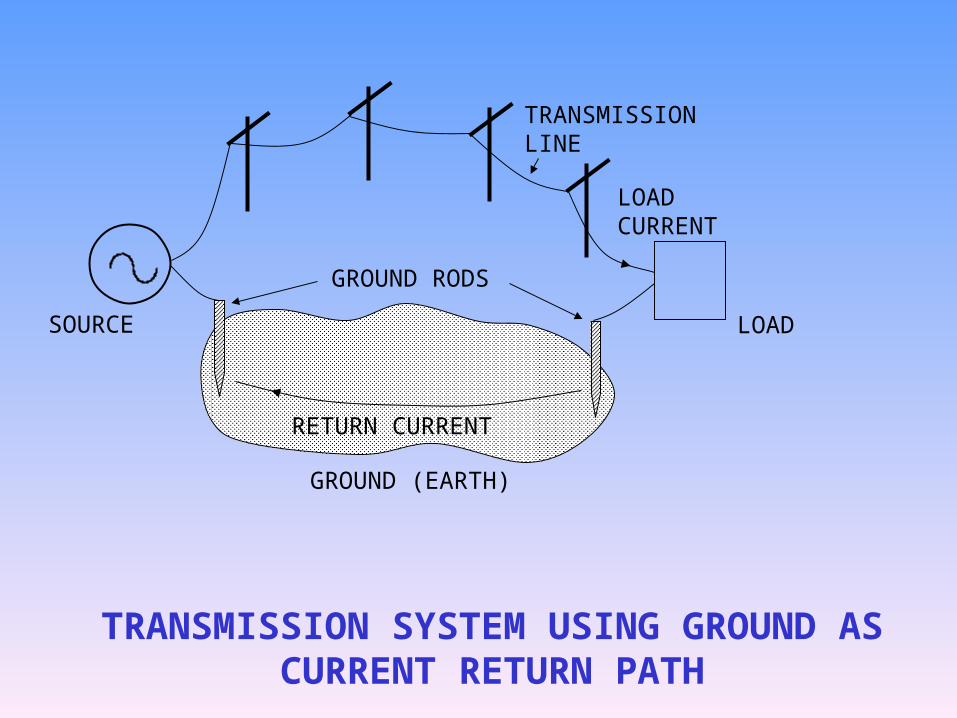
TRANSMISSION LINE
LOAD CURRENT
RETURN CURRENT
LOADSOURCE
GROUND (EARTH)
GROUND RODS
TRANSMISSION SYSTEM USING GROUND AS CURRENT RETURN PATH
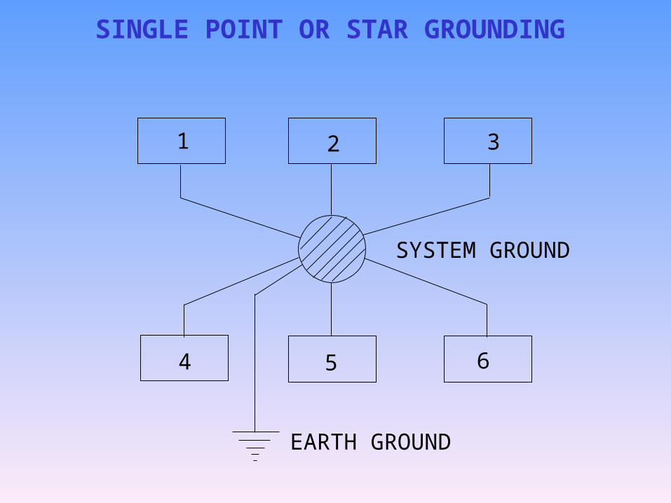
1 2 3
4 5 6
SYSTEM GROUND
EARTH GROUND
SINGLE POINT OR STAR GROUNDING
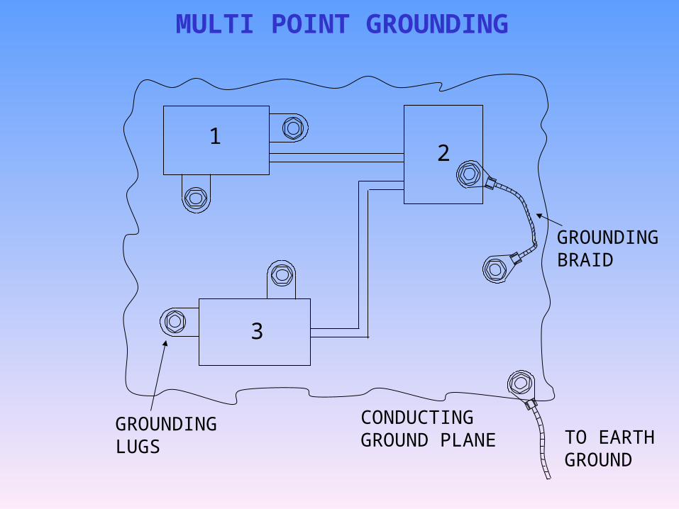
MULTI POINT GROUNDING
12
3
GROUNDING BRAID
TO EARTH GROUND
CONDUCTING GROUND PLANE
GROUNDING LUGS
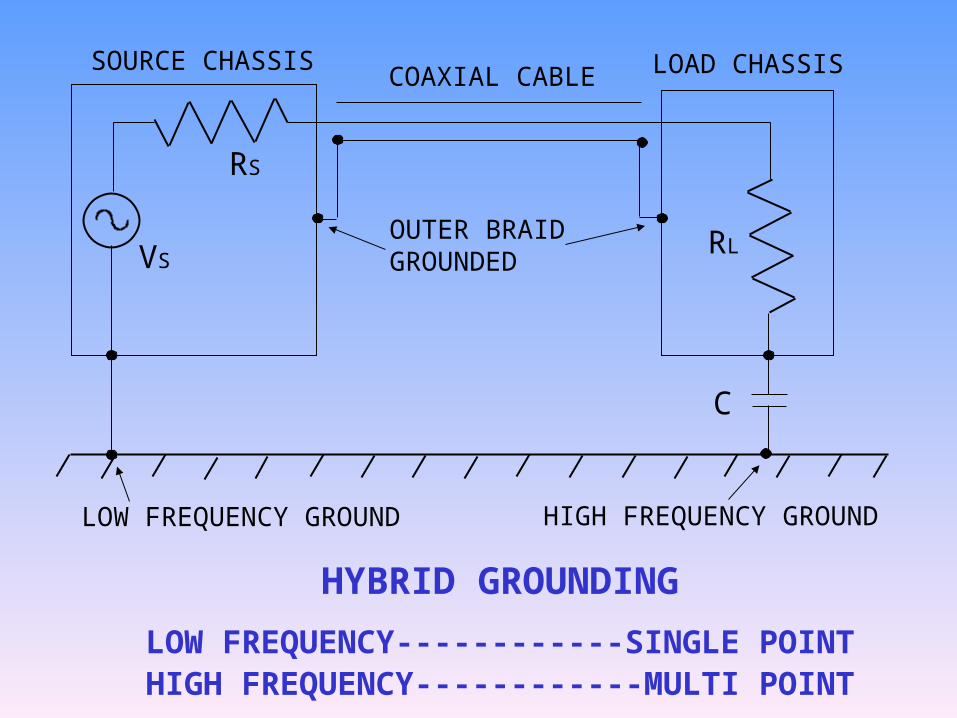
RS
VSRL
COAXIAL CABLE
OUTER BRAID GROUNDED
SOURCE CHASSIS LOAD CHASSIS
LOW FREQUENCY GROUND HIGH FREQUENCY GROUND
C
HYBRID GROUNDING
LOW FREQUENCY------------SINGLE POINTHIGH FREQUENCY------------MULTI POINT
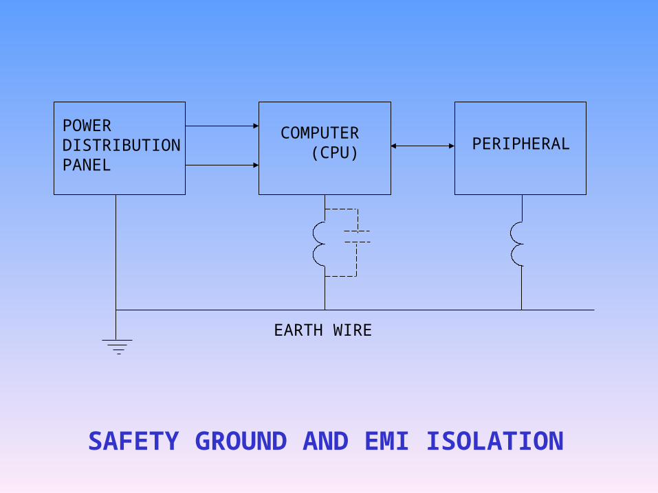
SAFETY GROUND AND EMI ISOLATION
POWER DISTRIBUTION PANEL
COMPUTER (CPU) PERIPHERAL
EARTH WIRE
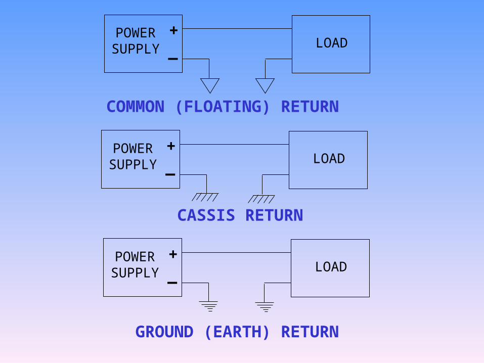
LOADPOWER SUPPLY
+_
LOADPOWER SUPPLY
+_
LOADPOWER SUPPLY
+_
COMMON (FLOATING) RETURN
CASSIS RETURN
GROUND (EARTH) RETURN
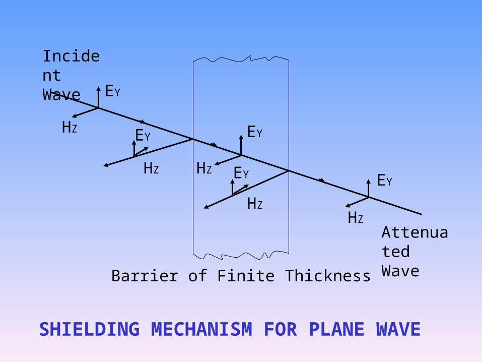
Barrier of Finite Thickness
SHIELDING MECHANISM FOR PLANE WAVE
Incident Wave
Attenuated Wave
EY
EY
EYEY
EYHZ
HZ
HZ
HZ
HZ
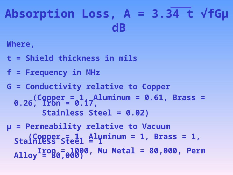
Absorption Loss, A = 3.34 t √fGµ dBWhere,
t = Shield thickness in mils
f = Frequency in MHz
G = Conductivity relative to Copper
(Copper = 1, Aluminum = 0.61, Brass = 0.26, Iron = 0.17, Stainless Steel = 0.02)
µ = Permeability relative to Vacuum (Copper = 1, Aluminum = 1, Brass = 1, Stainless Steel = 1 Iron = 1000, Mu Metal = 80,000, Perm Alloy = 80,000)
• 1 mil of Copper at 1 GHz shall give over 100 dB absorption loss
• 1/8 inch (~ 0.3 cm) Iron sheet at 50 Hz gives 50 dB absorption loss
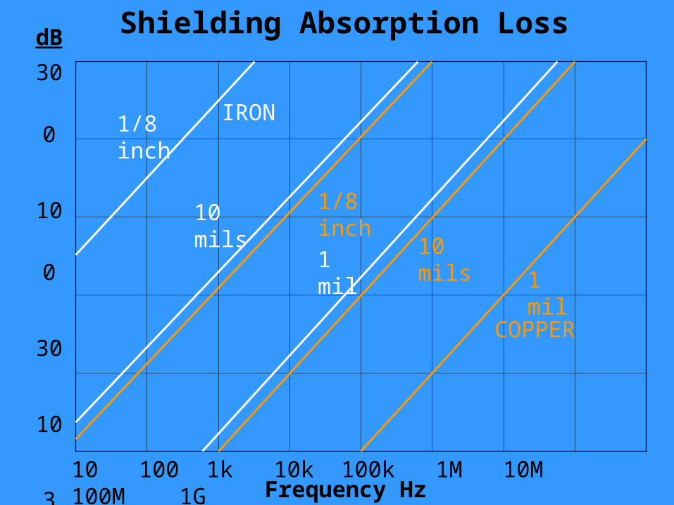
Shielding Absorption Loss
300
100
30
10
3
1
dB
Frequency Hz10 100 1k 10k 100k 1M 10M 100M 1G
IRON
COPPER
1 mil
10 mils
1/8 inch
1/8 inch10 mils
1 mil
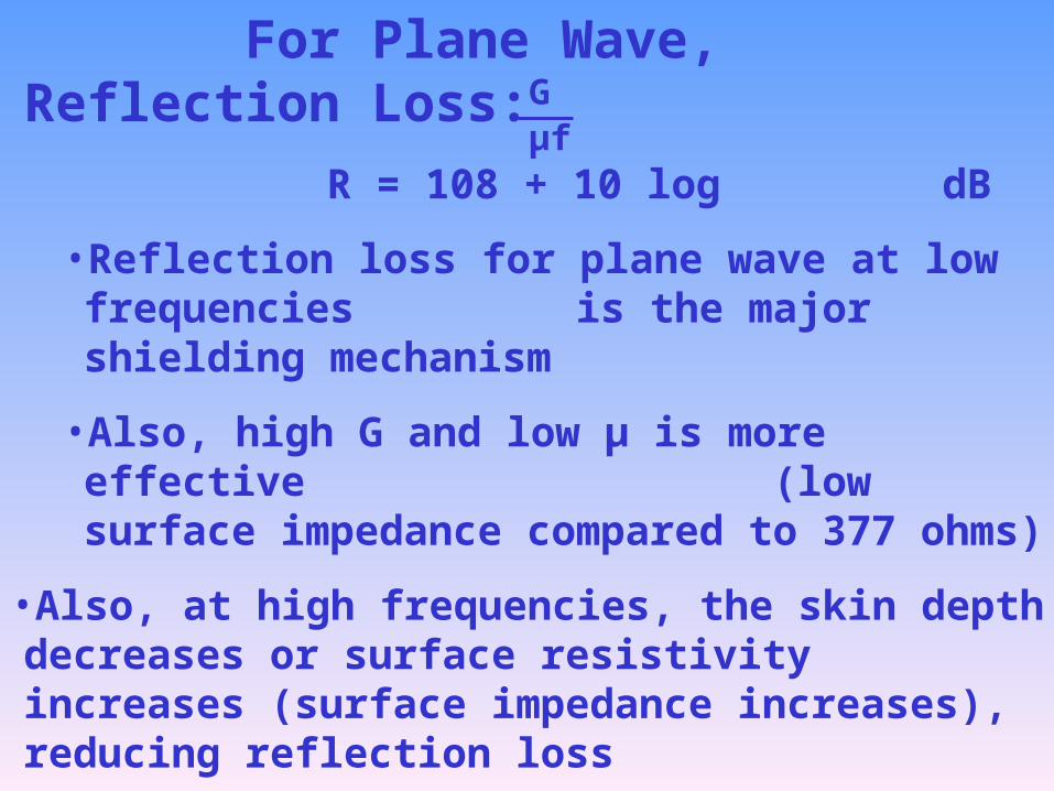
For Plane Wave, Reflection Loss:
R = 108 + 10 log dB
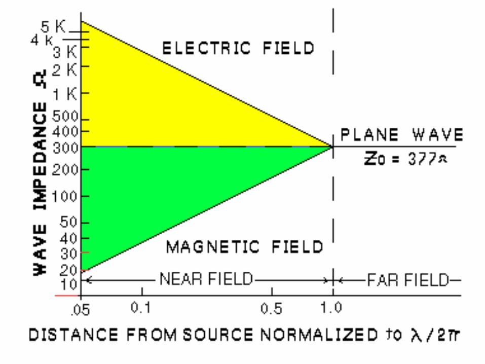
• Reflection loss for plane wave at low frequencies is the major shielding mechanism
• Also, high G and low µ is more effective (low surface impedance compared to 377 ohms)
•Also, at high frequencies, the skin depth decreases or surface resistivity increases (surface impedance increases), reducing reflection loss
•At VHF and UHF, absorption loss is more important
Gµf
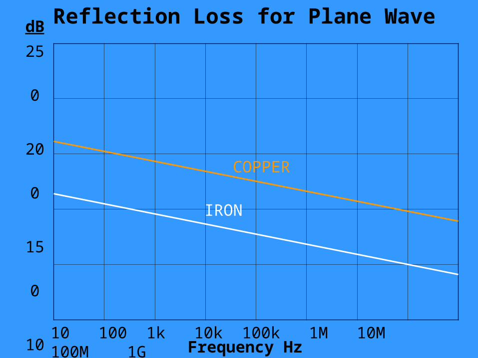
Reflection Loss for Plane Wave
250
200
150
100
50
0
dB
Frequency Hz10 100 1k 10k 100k 1M 10M 100M 1G
IRON
COPPER
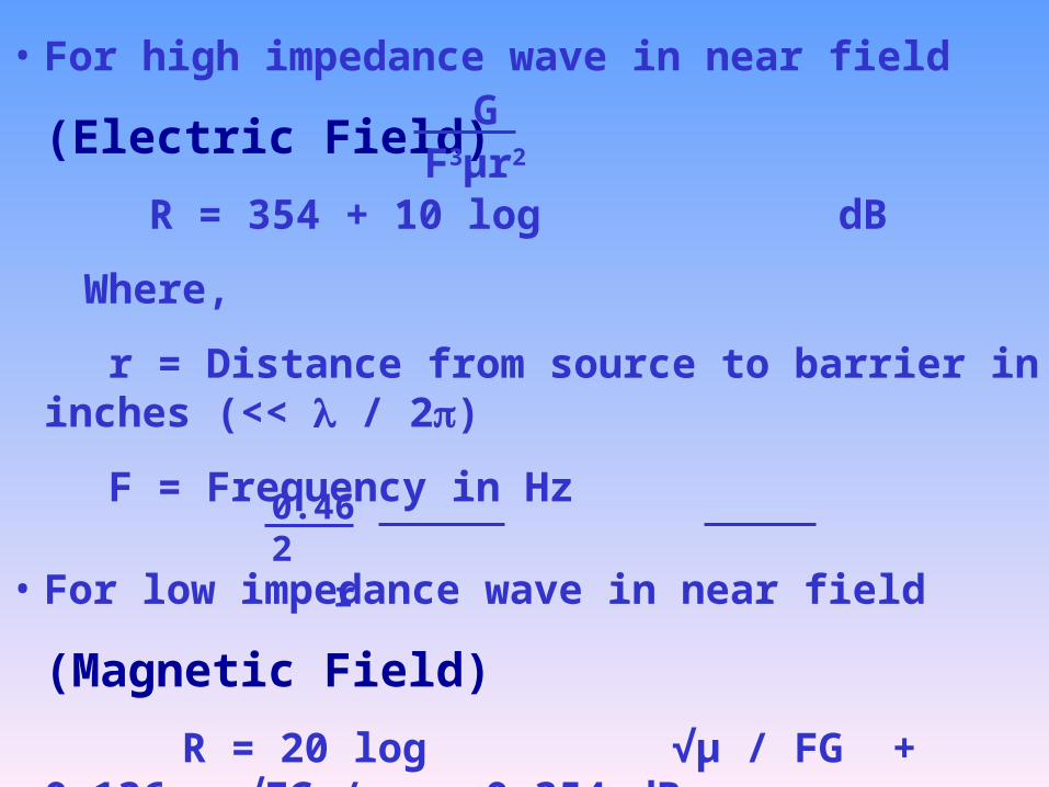
• For high impedance wave in near field (Electric Field)
R = 354 + 10 log dB
Where,
r = Distance from source to barrier in inches (<< / 2)
F = Frequency in Hz
• For low impedance wave in near field (Magnetic Field)
R = 20 log √µ / FG + 0.136 r √FG / µ + 0.354 dB
An interesting condition is achieved for magnetic field reflection loss for iron with 1 inch separation, where it approaches 0 dB at 30 kHz indicating matching of wave impedance and surface impedance
0.462 r
GF3µr2
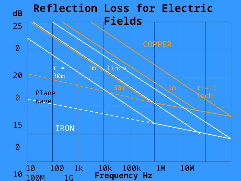
Reflection Loss for Electric Fields
250
200
150
100
50
0
dB
Frequency Hz10 100 1k 10k 100k 1M 10M 100M 1G
IRON
COPPER
r = 30m 1m 1inch
r = 1 inch1m30mPlane Wave
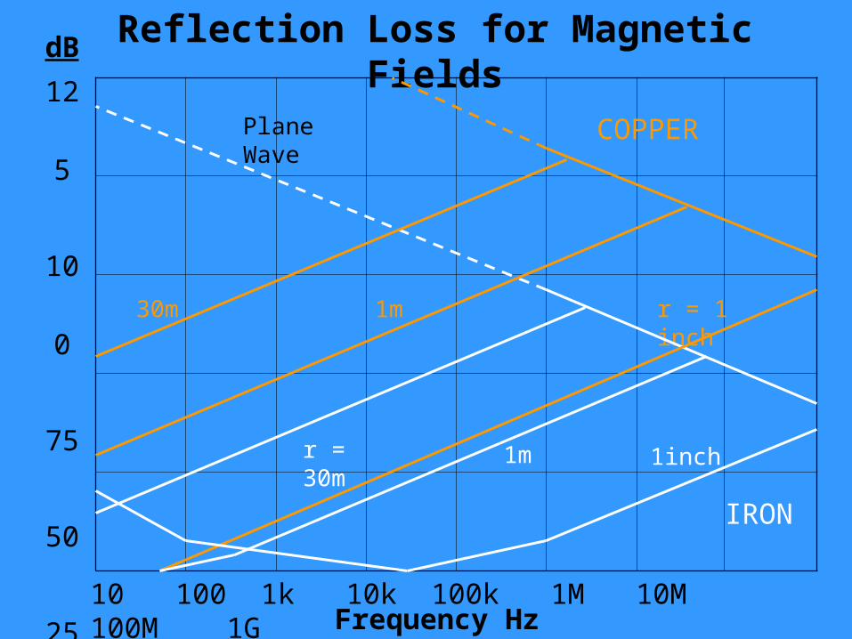
Reflection Loss for Magnetic Fields
125
100
75
50
25
0
dB
Frequency Hz10 100 1k 10k 100k 1M 10M 100M 1G
IRON
COPPER
r = 30m 1m 1inch
r = 1 inch1m30m
Plane Wave
ELECTRIC FIELD COUPLING
•Also called capacitive coupling increases with increase in circuit impedance and is the primary contributor at high frequencies
•To reduce electric field coupling
•Isolate the culprit circuit
•Shortest possible, point to point wiring
•Faraday shielding
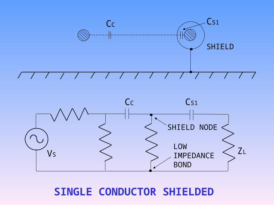
CC CS1
CC CS1
SHIELD
SHIELD NODE
LOW IMPEDANCE BOND
VS ZL
SINGLE CONDUCTOR SHIELDED
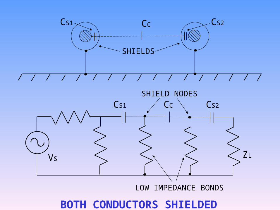
CC CS2
CC CS2
SHIELDS
SHIELD NODES
LOW IMPEDANCE BONDS
VS ZL
BOTH CONDUCTORS SHIELDED
CS1
CS1
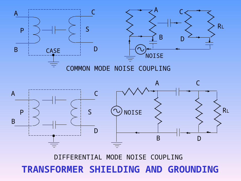
TRANSFORMER SHIELDING AND GROUNDING
DIFFERENTIAL MODE NOISE COUPLING
COMMON MODE NOISE COUPLING
CASENOISE
NOISE
A A
A
A
B
B
B
B
C
C
C
C
D
DD
DP
P
S
S
RL
RL
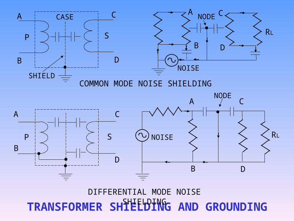
TRANSFORMER SHIELDING AND GROUNDING
DIFFERENTIAL MODE NOISE SHIELDING
COMMON MODE NOISE SHIELDING
CASE
NOISE
NOISE
A A
A
A
B
B
B
B
C
C
C
C
D
DD
DP
P
S
S
RL
RL
SHIELD
NODE
NODE
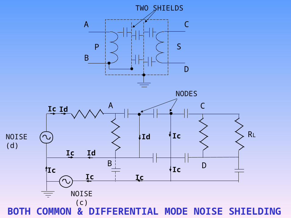
BOTH COMMON & DIFFERENTIAL MODE NOISE SHIELDING
NOISE (d)
A
A
B
B
C
C
D
D
P S
RL
TWO SHIELDS
NODES
NOISE (c)
Ic
Ic
Ic
Ic IcIc
Ic
Id
Id
Id
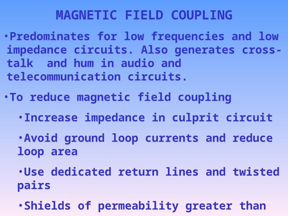
MAGNETIC FIELD COUPLING
•Predominates for low frequencies and low impedance circuits. Also generates cross-talk and hum in audio and telecommunication circuits.
•To reduce magnetic field coupling
•Increase impedance in culprit circuit
•Avoid ground loop currents and reduce loop area
•Use dedicated return lines and twisted pairs
•Shields of permeability greater than one
•Sensitive circuits should be used in differential mode
•Use of isolation transformers and optical couplers
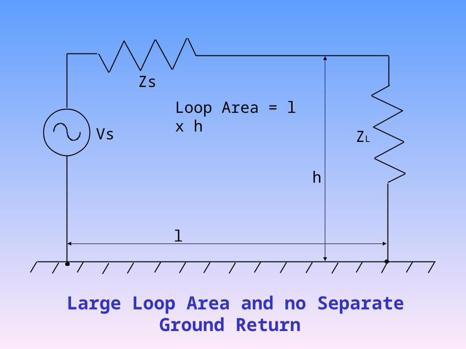
Vs
Zs
ZL
Loop Area = l x h
l
h
Large Loop Area and no Separate Ground Return
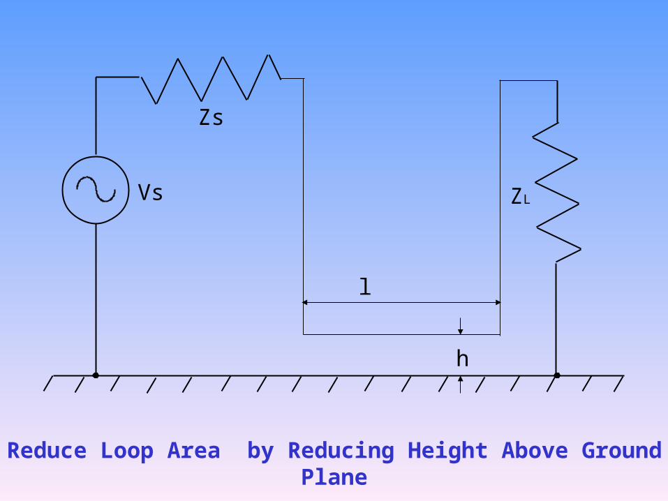
Vs
Zs
ZL
l
h
Reduce Loop Area by Reducing Height Above Ground Plane
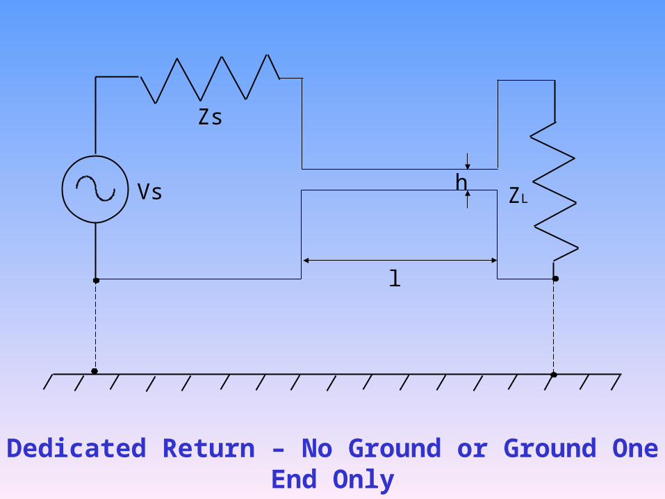
Vs
Zs
ZL
l
h
Dedicated Return – No Ground or Ground One End Only
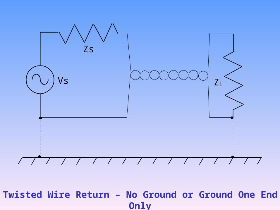
Vs
Zs
ZL
Twisted Wire Return – No Ground or Ground One End Only
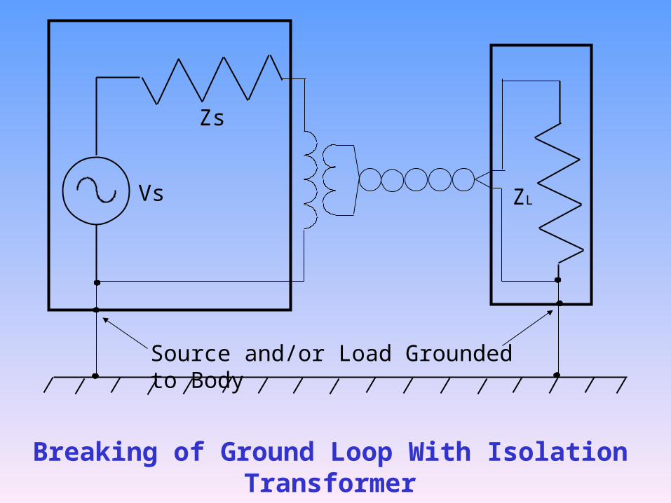
Vs
Zs
ZL
Breaking of Ground Loop With Isolation Transformer
Source and/or Load Grounded to Body
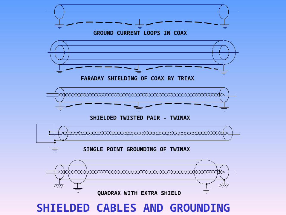
SHIELDED CABLES AND GROUNDING
FARADAY SHIELDING OF COAX BY TRIAX
GROUND CURRENT LOOPS IN COAX
SHIELDED TWISTED PAIR – TWINAX
SINGLE POINT GROUNDING OF TWINAX
QUADRAX WITH EXTRA SHIELD
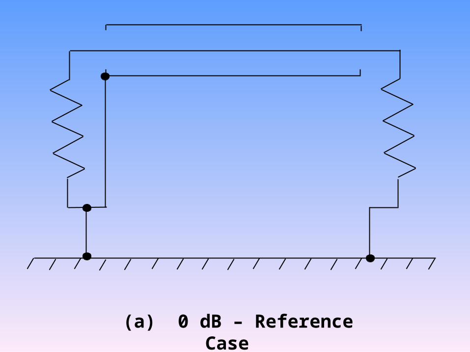
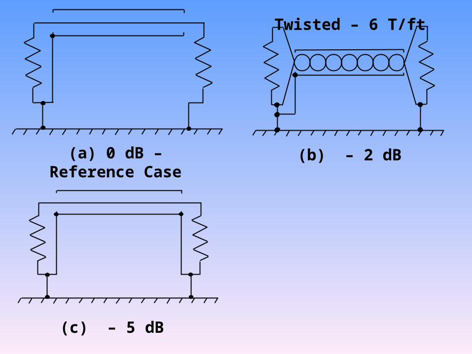
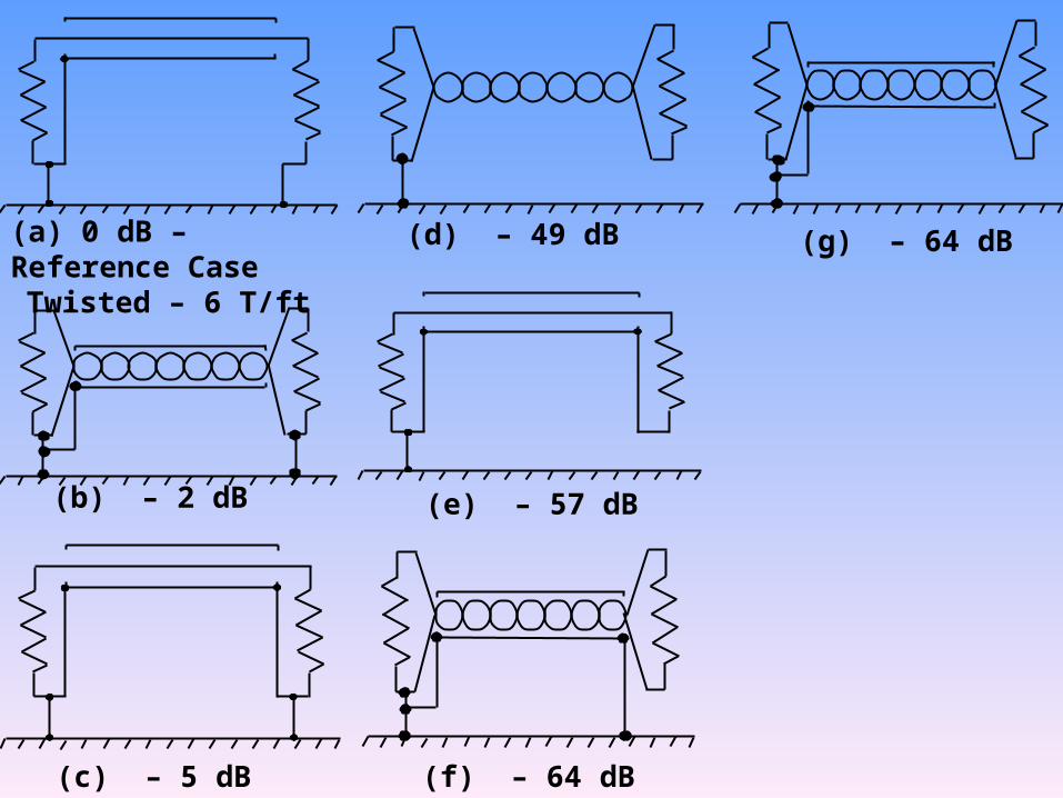
(a) 0 dB – Reference Case
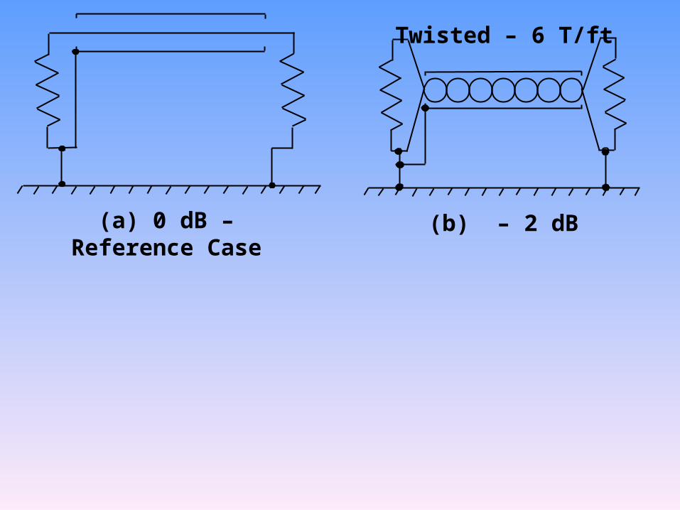
(a) 0 dB – Reference Case (b) – 2 dB
Twisted – 6 T/ft
(a) 0 dB – Reference Case (b) – 2 dB
(c) – 5 dB
Twisted – 6 T/ft
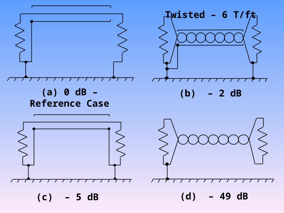
(a) 0 dB – Reference Case (b) – 2 dB
(c) – 5 dB (d) – 49 dB
Twisted – 6 T/ft
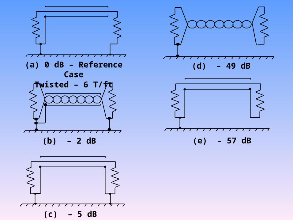
(a) 0 dB – Reference Case
(b) – 2 dB
(c) – 5 dB
(d) – 49 dB
Twisted – 6 T/ft
(e) – 57 dB
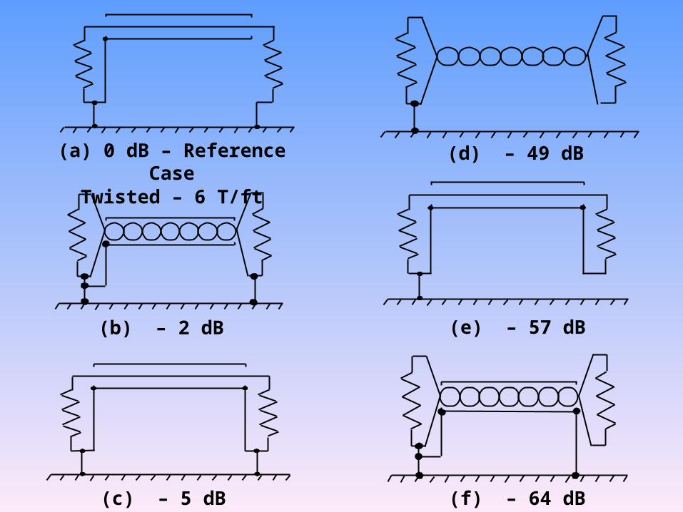
(a) 0 dB – Reference Case
(b) – 2 dB
(c) – 5 dB
(d) – 49 dB
Twisted – 6 T/ft
(f) – 64 dB
(e) – 57 dB
(a) 0 dB – Reference Case
(b) – 2 dB
(c) – 5 dB
(d) – 49 dB
Twisted – 6 T/ft
(f) – 64 dB
(e) – 57 dB
(g) – 64 dB
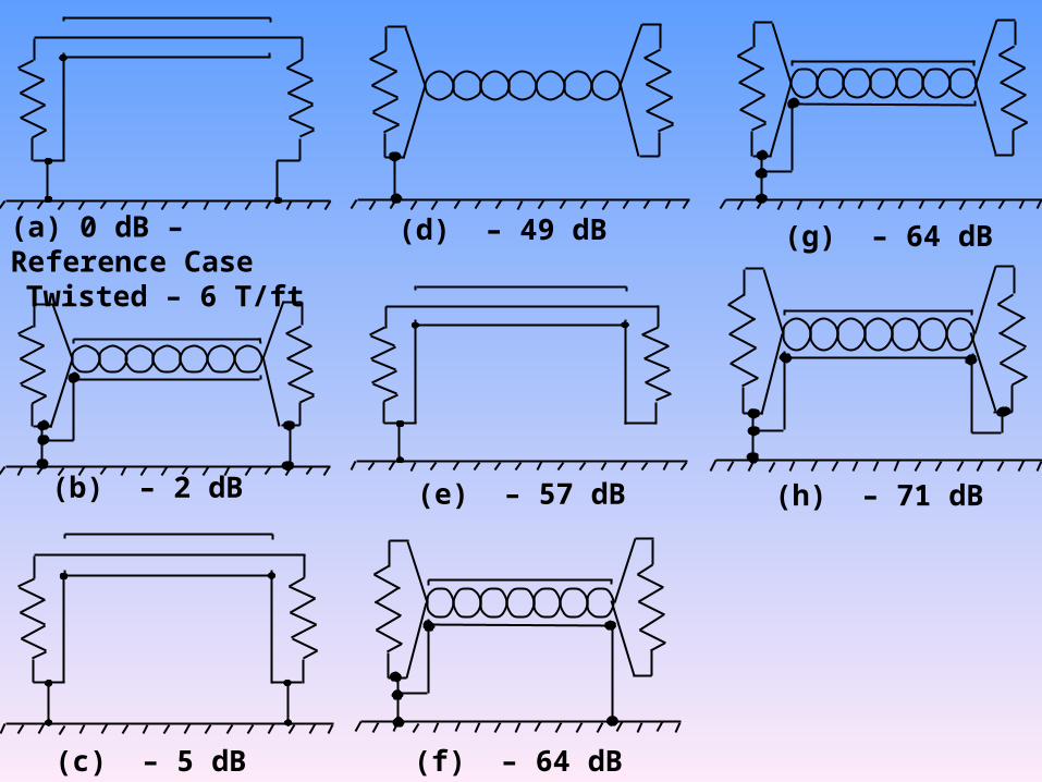
(a) 0 dB – Reference Case
(b) – 2 dB
(c) – 5 dB
(d) – 49 dB
Twisted – 6 T/ft
(f) – 64 dB
(e) – 57 dB
(g) – 64 dB
(h) – 71 dB
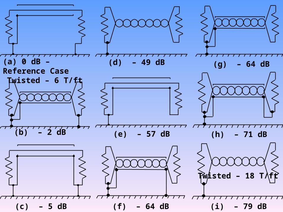
(a) 0 dB – Reference Case
(b) – 2 dB
(c) – 5 dB
(d) – 49 dB
Twisted – 6 T/ft
(f) – 64 dB
(e) – 57 dB
(g) – 64 dB
(h) – 71 dB
(i) – 79 dB
Twisted – 18 T/ft
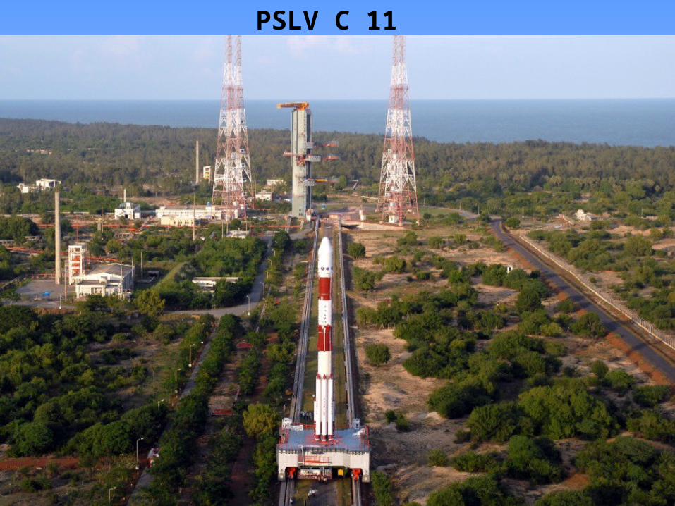
PSLV C 11
PSLV C 11

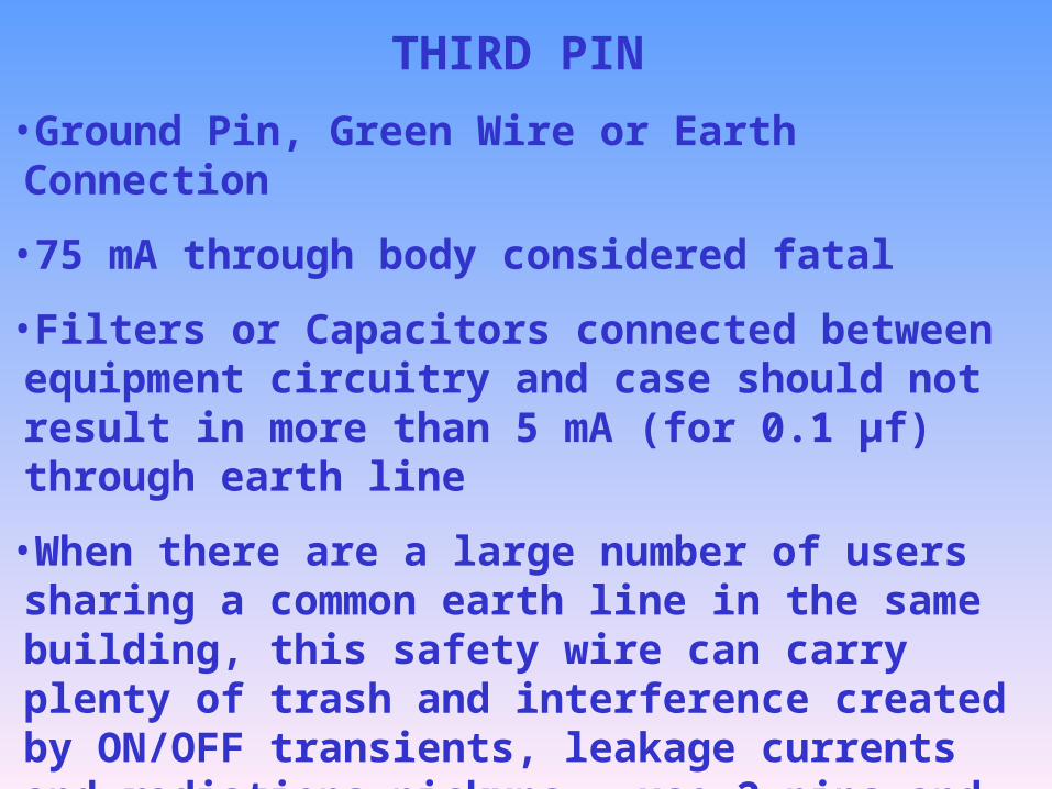
THIRD PIN
•Ground Pin, Green Wire or Earth Connection
•75 mA through body considered fatal
•Filters or Capacitors connected between equipment circuitry and case should not result in more than 5 mA (for 0.1 µf) through earth line
•When there are a large number of users sharing a common earth line in the same building, this safety wire can carry plenty of trash and interference created by ON/OFF transients, leakage currents and radiations pickups – use 2 pins and non-metallic body
•Obviously, one should not share the ground line with lightning earth strip or water plumbing

Thank You