Embed Size (px)
Citation preview

OPERATOR’SMANUAL
FORM NO. 3318-239 GB Rev. B
MODEL NO. 30233TE—60001 & UP
2-Wheel and 4-Wheel Drive Traction Units
MODEL NO. 30243TE—60001 & UP
GROUNDSMASTER® 223D ®
© The Toro Company—1996

To assure maximum safety, optimum performance,and to gain knowledge of the product, it is essentialthat you or any other operator of the mower read andunderstand the contents of this manual before theengine is ever started. Pay particular attention to theSAFETY INSTRUCTIONS highlighted by this sym-bol:
The safety alert symbol means CAUTION, WARN-ING or DANGER—personal safety instruction.Failure to comply with the instruction may result inpersonal injury.
FOREWORD
The GROUNDSMASTER 223-D was developed tosatisfy the demand for a maneuverable, intermediatesize, turf maintenance rotary mower. The machinehas advanced concepts in engineering, design andsafety; and if maintained properly, it will give excel-lent service.
Since the GROUNDSMASTER 223-D is a highquality product, Toro is concerned about the futureuse of the machine and the safety of the user. Readthis manual to familiarize yourself with the properset up, operation, and maintenance instructions.
Certain information in this manual is emphasized.DANGER, WARNING and CAUTION identify per-sonal safety related information. IMPORTANT iden-tifies mechanical information demanding specialattention. Be sure to read the directive because itdeals with the possibility of damaging a part or partsof the machine. NOTE identifies general informationworthy of special attention.
If help concerning set up, operation, maintenance orsafety is ever needed, contact a local AuthorizedToro Distributor. In addition to genuine Toro replace-ment parts, the distributor also has optional equip-ment form the complete line of Toro turf care equip-ment. Keep your Toro all Toro – buy genuine Tororeplacement parts and accessories.
Whenever you have questions or need service, con-tact your local authorized Toro Distributor. In addi-tion to having a complete line of accessories andprofessional turf care service technicians, the distrib-utor has a complete line of genuine TORO replace-ment parts to keep your machine operating properly.
Keep your TORO all TORO. Buy genuine TOROparts and accessories.
TABLE OF CONTENTS
SAFETY INSTRUCTIONS 3
SPECIFICATIONS 9
BEFORE OPERATING 11
CONTROLS 15
OPERATING INSTRUCTIONS 17
LUBRICATION 20
QUICK REFERENCE AID 22
PREPARATION FOR SEASONAL STORAGE 23
PRODUCT IDENTIFICATION 23
2

3
Safety
Training
1. Read the instructions carefully. Be familiarwith the controls and the proper use of theequipment.
2. Never allow children or people unfamiliar withthese instructions to use the lawnmower. Localregulations may restrict the age of the operator.
3. Never mow while people, especially children, orpets are nearby.
4. Keep in mind that the operator or user isresponsible for accidents or hazards occurringto other people or their property.
5. Do not carry passengers.
6. All drivers should seek and obtain professionaland practical instruction. Such instructionshould emphasize:
• the need for care and concentration whenworking with rideon machines;
• control of a ride on machine sliding on aslope will not be regained by the applicationof the brake. The main reasons for loss ofcontrol are:
– insufficient wheel grip;
– being driven too fast;
– inadequate braking;
– the type of machine is unsuitable for itstask;
– lack of awareness of the effects of groundconditions, especially slopes;
Preparation
1. While mowing, always wear substantialfootwear and long trousers. Do not operate theequipment when barefoot or wearing open san-dals.
2. Thoroughly inspect the area where the equip-ment is to be used and remove all objects whichmay be thrown by the machine.
3. WARNING—Petrol is highly flammable.
• Store fuel in containers specifically designedfor this purpose.
• Refuel outdoors only and do not smokewhile refueling.
• Add fuel before starting the engine. Neverremove the cap of the fuel tank or add petrolwhile the engine is running or when theengine is hot.
• If petrol is spilled, do not attempt to start theengine but move the machine away from thearea of spillage and avoid creating anysource of ignition until petrol vapors havedissipated.
• Replace all fuel tanks and container capssecurely.
4. Replace faulty silencers.
5. Before using, always visually inspect to see thatthe blades, blade bolts and cutter assembly arenot worn or damaged. Replace worn or dam-aged blades and bolts in sets to preserve bal-ance.
6. On multi-bladed machines, take care as rotatingone blade can cause other blades to rotate.
Operation
1. Do not operate the engine in a confined spacewhere dangerous carbon monoxide fumes cancollect.
2. Mow only in daylight or in good artificial light.
3. Before attempting to start the engine, disengageall blade attachment clutches and shift into neu-tral.
4. Do not use on slopes of more than:
• Never mow side hills over 5°
• Never mow uphill over 10°
• Never mow downhill over 15°
5. Remember there is no such thing as a “safe”slope. Travel on grass9 slopes requires particu-
Safety
4
lar care. To guard against overturning:
• do not stop or start suddenly when going upor downhill;
• engage clutch slowly, always keep machinein gear, especially when travailing downhill;
• machine speeds should be kept low onslopes and during tight turns;
• stay alert for bumps and hollows and otherhidden hazards;
• never mow across the face of the slope,unless the lawnmower is designed for thispurpose.
6. Use care when pulling loads or using heavyequipment.
• Use only approved drawbar hitch points.
• Limit loads to those you can safely control.
• Do not turn sharply. Use care when revers-ing.
• Use counterweight(s) or wheel weights whensuggested in the instruction handbook .
7. Watch out for traffic when crossing or nearroadways.
8. Stop the blades rotating before crossing surfacesother than grass.
9. When using any attachments, never direct dis-charge of material toward bystanders nor allowanyone near the machine while in operation .
10. Never operate the lawnmower with defectiveguards, shields or without safety protectivedevices in place.
11. Do not change the engine governor settings oroverspeed the engine. Operating the engine atexcessive speeds may increase the hazard ofpersonal injury.
12. Before leaving the operator's position:
• disengage the power take-off and lower theattachments;
• change into neutral and set the parkingbrake;
• stop the engine and remove the key.
13. Disengage drive to attachments, stop the engine,and disconnect the spark plug wire(s)or removethe ignition key
• before cleaning blockages or uncloggingchute;
• before checking, cleaning or working on thelawnmower;
• after striking a foreign object. Inspect thelawnmower for damage and make repairsbefore restarting and operating the equip-ment;
• if the machine starts to vibrate abnormally(check immediately).
14. Disengage drive to attachments when transport-ing or not in use.
15. Stop the engine and disengage drive to attach-ment
• before refueling;
• before removing the grass catcher;
• before making height adjustment unlessadjustment can be made from the operator'sposition.
16. Reduce the throttle setting during engine runoutand, if the engine is provided with a shutoffvalve, turn the fuel off at the conclusion ofmowing.
Maintenance and Storage
1. Keep all nuts, bolts and screws tight to be surethe equipment is in safe working condition.
2. Never store the equipment with petrol in thetank inside a building where fumes may reachan open flame or spark.
3. Allow the engine to cool before storing in anyenclosure.
4. To reduce the fire hazard, keep the engine,silencer, battery compartment and petrol storagearea free of grass, leaves, or excessive grease.
5. Check the grass catcher frequently for wear or

5
Safety
deterioration.
6. Replace worn or damaged parts for safety.
7. If the fuel tank has to be drained, this should bedone outdoors
8. On multi-bladed machines, take care as rotatingone blade can cause other blades to rotate.
9. When machine is to be parked, stored or leftunattended, lower the cutting means unless apositive mechanical lock is used.
Sound & Vibration Levels
Sound Levels
This unit has an equivalent continuous A-weightedsound pressure at the operator ear of: 80 dB(A),based on measurements of identical machines per84/538/EEC.
This unit has a sound power level of 104dB(A)/1pW, based on measurements of identicalmachines per procedures outlined in Directive84/538/EEC and amendments
Vibration Levels
This unit has a vibration level of 5.0 m/s2 at thehands, based on measurements of identical machinesper ISO 5349 procedures.
This unit does not exceed a vibration level of 0.5m/s2 at the posterior based on measurements of iden-tical machines per ISO 2631 procedures.

6
Symbol Glossary
Caustic liquids, chemical burns to fingers or hand
Poisonous fumes or toxic gases, asphyxiation
Electrical shock,electrocution
High pressurefluid, injection into body
High pressurespray, erosion offlesh
High pressurespray, erosion offlesh
Crushing of fingers or hand, force applied from above
Crushing of toes or foot, forceapplied from above
Crushing of whole body, applied from above
Crushing of torso, force applied from side
Crushing of fingers or hand/, force applied from side
Crushing of whole body
Crushing of head, torso and arms
Cutting of fingers or hand
Cutting of footCrushing of leg, force applied from side
Severing of fingers or hand, mower blade
Severing of toes or foot, mower blade
Severing of toes or fingers, rotary mower blade
Cutting or entanglement of foot, rotating auger
Severing of foot, rotating knives
Severing of fingers or hand, impeller blade
Dismember-ment, front engine mower in forward motion
Dismember-ment, front engine mower in rearward motion
Severing offingers or hand, engine fan
Whole body entanglement, implement input drive line
Fingers or hand entangle-ment, chain drive
Hand & armentanglement,belt drive
Thrown or flying objects, wholebody exposure
Thrown or flying objects, face exposure
Thrown or flyingobjects, rotary mover
Runover/back-over, vehicle
Machine tipping, riding mower
Machine rollover,ROPS (rear engine mower)
Stored energyhazard, kickbackor upward motion
Hot surfaces, burns to fingers or hands
Explosion Fire or open flame
Secure lifting cylinder with locking device before getting in hazardous area
Do not step on loading platform if PTO is connect-ed to tractor & engine is running
Do not step Wait until all machine comp-onents have completely stopped before touching them
Shut off engine & remove key before perform-ing maintenance or repair work
Stay a safe distance from the machine
Stay clear of articulation area while engine is running
Do not open or remove safety shields while engine is running
Riding on this machine is allowed only on a passen-ger seat & only if the driver’s view is not hindered

7
Safety
Fasten seat belts
Safety alert triangle
Outline safetyalert symbol
Read operator’s manual
Fire, open light and smoking prohibited
Eye protection must be worn
Consult technical manual for proper service procedures
Hearingprotection must be worn
Caution, toxic risk
Head protection must be worn
Flush with water Engine Transmission Hydraulic systemFirst aid
Oil Coolant (water) Intake air Exhaust gas Pressure Level indicator Liquid levelBrake system
DisengageFilter Temperature Failure/Malfunction
Start switch/mechanism
On/start Off/stop Engage
Plus/increase/positive polarity
Minus/decrease/negative polarity
Horn Battery chargingcondition
Hourmeter/elapsed operating hours
Fast Slow Continuousvariable, linear
Volume empty Volume full Machine travel direction, forward/rearward
Control lever operating direction, dual direction
Control leveroperating direction, multipledirection
Clockwise rotation
Counter-clock-wise rotation
Grease lubrication point
Oil lubrication point
Lift point Jack or support point
Draining/emptying
Engine lubricat-ing oil
Engine lubricating oil pressure
Engine lubricating oil level
Engine lubricating oil filter
Engine lubricating oil temperature
Engine coolant Engine coolant pressure
Engine coolant filter
Engine coolanttemperature
Engine intake/combustion air
Engine intake/com-bustion air pressure
Engine intake/air filter

Safety
8
Engine start Engine stop Engine failure/malfunction
Engine rotational speed/frequency
Choke Primer (start aid) Electrical preheat (low temperature start aid)
n/minTransmission oil
Transmission oil pressure
Transmission oil temperature
Transmission failure/malfunction
Clutch Neutral High Low Forward
N H L F
Reverse Park First gear Second gear Third gear (other #'s may be used until the maximum # of forward gears is reached.)
Hydraulic oil Hydraulic oilpressure
Hydraulic oillevel
R P 2 31
Hydraulic oil filter
Hydraulic oiltemperature
Hydraulic oilfailure/malfunction
Fuel levelParking brake Fuel Fuel filter Fuel systemfailure/malfunction
Lock Unlock Differential lock 4-Wheel drive Power Take-OffDiesel fuel Unleaded fuel Headlights
Cutting unit, lower
Cutting unit, hold
Cutting unit,float
Cutting unit Cutting unit, raise
Power Take-Off,rotational speed
Blade cutting element
Blade cutting element, height adjustment
Cutting unit, transport position
Cutting unit, raise to transport position
Cutting unit, lower to transport position
Attachment lower
Attachment raise
Spacing distance Snow thrower, collector auger
Traction
Above working temperature range
Drilling Manual metal arc welding
Manual Water pump Keep dry Weight Do not dispose in the garbage
CE logo

Engine: Manufacturer—Mitsubishi.Horsepower—22 (16 Kw) @ 3000 RPM.Torque—40 ft-lb (54.2 Nm) @ 2400 RPM.Displacement—58.1 cu in. (952 cc).Crankcase Capacity—3.8 qt. (3.6 L).Governor—Mechanical.Governor Limit—3100–3250 RPM.Idle Speed—1700 RPM.
Air Cleaner: Donaldson heavy duty with preclean-er. Remote mounted.
Fuel Tank Capacity: 8.5 gal. (32 l).
Fuel Filter/Water Separator: 3-micron spin–ontype element. Replaceable (Toro Part No. 63-8300).
Fuel Pump: 12-volt electric (transistor type)w/replaceable fuel filter (Toro Part No. 43-2550).
Cooling System:Radiator—6 qt (5.7 l) capacity.Expansion Tank—Remote mounted; 1 qt (0.946 l)capacity. System contains a 50/50 mix of ethyleneglycol anti-freeze and water.
Electrical: Battery—12 volt, BCI group size 26, 530Amp at 0° F. 35-amp alternator with regulator/rectifi-er.
Drive Coupling: Transmission driven by steel shaftwith flexible rubber couplings at each end.
Transmission:Manufacturer & Type—Sundstrand hydrostatic, TypeU15.Normal Charge Pressure – 70–150 psi
(483–1034 kPa).Implement Relief Setting – 700–800 psi
(4 826 – 5 516 kPa).
Hydraulic Filter: 25-micron mounted directly totransmission. Replaceable (Toro Part No. 23-2300).
Drive Axle: Manufacturer – Dana Corp., ModelGT–20. Axle serves as a hydraulic fluid reservoirand mates directly with the transmission.Approximately 5 qt (4.7 l) capacity. 4-Wheel Drivehas mechanical rear axle coupled to front axle by adrive shaft and clutch.
Brakes: Mechanical drum type, 7 in. (17.8 cm) dia.
x 1-3/4 in. (45 mm) wide. Individually controlled bytwo pedals connected by cable and conduit for steer-ing assist. Pedals may be latched together for twowheel braking. Lever provided for the parkingbrake.
Tires, Wheels, Pressure:Front Tires—23 x 8.50 - 12Rear Tires—16 x 6.50 - 8All tires 4 ply rating, tubeless type.Pressure—20 psi (138 kPa).
Steering: 13 in. (33 cm) steering wheel. TRW powersteering valve.
Main Frame: Frame is welded, formed steel.
Instrumentation: Fuel gauge, water temperaturegauge, hour meter and warning lights for high tem-perature shutdown, oil pressure, amperage and glowplug are mounted on the console.
Controls: Throttle, PTO switch, parking brake,implement lift, ignition switch and glow plug switchare all hand-operated. Forward/reverse traction pedaland turning brakes are foot operated.
PTO Drive: PTO shaft is clutched by a torque-teamed HA Section, spring tensioned V-belt directlyfrom the engine output shaft. PTO shaft engaged byelectric clutch/brake assembly. PTO speed – 2200RPM @ 3250 RPM engine speed.
Implement Connection—Universal joint and tele-scoping shaft assembly.
Lift Cylinders: Two, with 2 in. (51 mm) bore, 3.5in. (89 mm) stroke.
Interlock Switches: Prevents engine starting if trac-tion pedal or PTO switch are engaged. Stops theengine if operator leaves seat with either tractionpedal or PTO switch engaged.
Dimensions and Weight:Length: 208 cm (82 in.)Width (2-Wheel drive): 111 cm (44 in.)
(4-Wheel drive): 119 cm (47 in)Height: 127 cm (50 in.)Weight: 418 kg (1120 lb)
9
Specifications

CHECK THE ENGINE OIL
The engine is shipped with 3.8 qt (3.6 l) of oil in thecrankcase; however, check the oil level before andafter you first start the engine.
1. Position the machine on a level surface.
2. Open the hood.
3. Remove the dipstick and wipe it with a cleanrag. Insert the dipstick into the tube and makesure it is seated fully. Remove the dipstick andcheck the level of oil (Fig. 1). If the oil level islow, add enough oil to raise the level to theFULL mark on the dipstick. Do not overfill(Fig. 2).
Figure 11. Engine oil dipstick2. Engine oil filter3. Oil drain plug
Note: If the level of oil is at the ADD mark onthe dipstick, add 1 pint (0.47 l) of oil andrecheck the level. Do not overfill.
4. The engine uses any high-quality 10W30 deter-gent oil having the American PetroleumInstitute – API–”service classification” CD.
IMPORTANT: Check the level of oil every 5operating hours or daily. Change oil afterevery 50 hours of operation.
Figure 21. Engine oil fill
5. Insert the dipstick into the tube.
CHECK COOLING SYSTEM
Clean debris off screen and front of radiator daily(Fig. 3), hourly if conditions are extremely dusty anddirty.
Figure 31. Radiator2. Radiator screen3. Screen channel
The cooling system is filled with a 50/50 solution ofwater and permanent ethylene glycol anti-freeze.Check the level of coolant at the beginning of eachday (Fig. 4) before starting the engine. Capacity ofthe cooling system is 6 quarts (5.7 l).
1. Carefully remove the radiator cap and the
10
Before Operating

expansion tank cap.
Figure 41. Radiator cap2. Expansion tank cap3. Expansion tank fill marks
2. Check the level of coolant in the radiator. Theradiator should be filled to the top of the fillerneck and the expansion tank filled to betweenthe marks on its side.
3. If the coolant level is low, replenish the system.DO NOT OVERFILL.
4. Install the radiator and expansion tank caps.
CHECK HYDRAULIC SYSTEMFLUID
The hydraulic system was designed to operate onany high quality detergent oil having the AmericanPetroleum Institute–API–“service classification” SF,CC or CD. Oil viscosity—weight—must be selectedaccording to anticipated ambient temperature.Temperature/viscosity recommendations are:
Expected Ambient Recommended ViscosityTemperature and type
Over 32°C SAE 30, Type SF, CC orCD
4–38° C SAE 10W-30 or 10W40Type SF, CC or CD
–1–10° C SAE 5W30, Type SF, CCor CD
Below –1° C Type “F” or “FA”Automatic Transmission Fluid
Note: Do not mix engine oil and automatic transmis-sion fluid or hydraulic component damage mayresult. When changing fluids, also change transmis-sion filter. DO NOT USE DEXRON II ATF.
The axle housing acts as the reservoir for the system.The transmission and axle housing are shipped fromthe factory with approximately 5 quarts (4.7 l) ofSAE 10W–30 engine oil. However, check the levelof transmission oil before the engine is first startedand daily thereafter.
1. Position the machine on a level surface. Placeall controls in their neutral position and start theengine. Run the engine at lowest possible RPMto purge the system of air. DO NOT ENGAGETHE PTO. Turn the steering wheel severaltimes fully to the left and right. Raise the cut-ting unit to extend the lift cylinders, aimingsteering wheels straight forward and stop theengine.
2. Remove the dipstick cap (Fig. 5) from fillerneck and wipe it with a clean cloth. Screw thedipstick cap finger-tight onto filler neck; thenremove it and check the level of fluid. If thelevel is not within 1/2 inch (13 mm) from thegroove in the dipstick (Fig. 5), add SAE10W–30 engine oil, or, if used, automatic trans-mission fluid to raise the level to groove mark.Do not overfill.
IMPORTANT: When adding transmissionfluid to the hydraulic system, use a funnelwith a fine wire screen—200 mesh or finer—and make sure funnel and transmission fluidare immaculately clean. This procedure pre-vents accidental contamination of thehydraulic system.
11
Before Operating
If the engine has been running, pressurized hotcoolant can escape and cause burns when theradiator cap is removed.
CAUTION
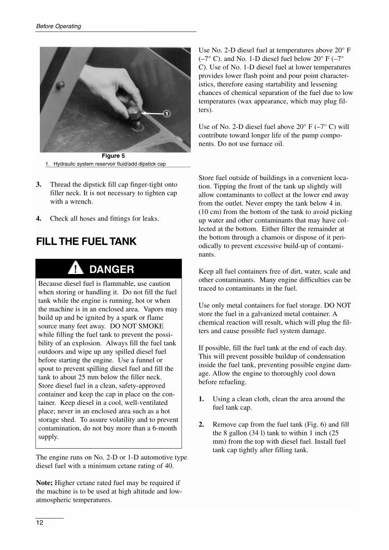
Figure 51. Hydraulic system reservoir fluid/add dipstick cap
3. Thread the dipstick fill cap finger-tight ontofiller neck. It is not necessary to tighten capwith a wrench.
4. Check all hoses and fittings for leaks.
FILL THE FUEL TANK
The engine runs on No. 2-D or 1-D automotive typediesel fuel with a minimum cetane rating of 40.
Note; Higher cetane rated fuel may be required ifthe machine is to be used at high altitude and low-atmospheric temperatures.
Use No. 2-D diesel fuel at temperatures above 20° F(–7° C). and No. 1-D diesel fuel below 20° F (–7°C). Use of No. 1-D diesel fuel at lower temperaturesprovides lower flash point and pour point character-istics, therefore easing startability and lesseningchances of chemical separation of the fuel due to lowtemperatures (wax appearance, which may plug fil-ters).
Use of No. 2-D diesel fuel above 20° F (–7° C) willcontribute toward longer life of the pump compo-nents. Do not use furnace oil.
Store fuel outside of buildings in a convenient loca-tion. Tipping the front of the tank up slightly willallow contaminants to collect at the lower end awayfrom the outlet. Never empty the tank below 4 in.(10 cm) from the bottom of the tank to avoid pickingup water and other contaminants that may have col-lected at the bottom. Either filter the remainder atthe bottom through a chamois or dispose of it peri-odically to prevent excessive build-up of contami-nants.
Keep all fuel containers free of dirt, water, scale andother contaminants. Many engine difficulties can betraced to contaminants in the fuel.
Use only metal containers for fuel storage. DO NOTstore the fuel in a galvanized metal container. Achemical reaction will result, which will plug the fil-ters and cause possible fuel system damage.
If possible, fill the fuel tank at the end of each day.This will prevent possible buildup of condensationinside the fuel tank, preventing possible engine dam-age. Allow the engine to thoroughly cool downbefore refueling.
1. Using a clean cloth, clean the area around thefuel tank cap.
2. Remove cap from the fuel tank (Fig. 6) and fillthe 8 gallon (34 l) tank to within 1 inch (25mm) from the top with diesel fuel. Install fueltank cap tightly after filling tank.
Before Operating
12
Because diesel fuel is flammable, use cautionwhen storing or handling it. Do not fill the fueltank while the engine is running, hot or whenthe machine is in an enclosed area. Vapors maybuild up and be ignited by a spark or flamesource many feet away. DO NOT SMOKEwhile filling the fuel tank to prevent the possi-bility of an explosion. Always fill the fuel tankoutdoors and wipe up any spilled diesel fuelbefore starting the engine. Use a funnel orspout to prevent spilling diesel fuel and fill thetank to about 25 mm below the filler neck.Store diesel fuel in a clean, safety-approvedcontainer and keep the cap in place on the con-tainer. Keep diesel in a cool, well-ventilatedplace; never in an enclosed area such as a hotstorage shed. To assure volatility and to preventcontamination, do not buy more than a 6-monthsupply.
DANGER
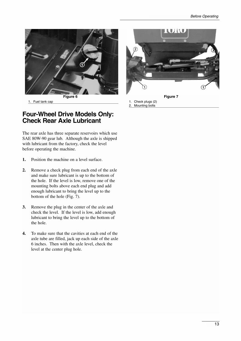
Figure 61. Fuel tank cap
Four-Wheel Drive Models Only:Check Rear Axle Lubricant
The rear axle has three separate reservoirs which useSAE 80W-90 gear lub. Although the axle is shippedwith lubricant from the factory, check the levelbefore operating the machine.
1. Position the machine on a level surface.
2. Remove a check plug from each end of the axleand make sure lubricant is up to the bottom ofthe hole. If the level is low, remove one of themounting bolts above each end plug and addenough lubricant to bring the level up to thebottom of the hole (Fig. 7).
3. Remove the plug in the center of the axle andcheck the level. If the level is low, add enoughlubricant to bring the level up to the bottom ofthe hole.
4. To make sure that the cavities at each end of theaxle tube are filled, jack up each side of the axle6 inches. Then with the axle level, check thelevel at the center plug hole.
Figure 71. Check plugs (2)2. Mounting bolts
13
Before Operating

Service Brakes (Fig. 8 )—The left and right brakepedals are connected to the left and right frontwheels. Since both brakes work independently ofeach other, the brakes can be used to turn sharply orto increase traction if one wheel tends to slip whileoperating on certain slope conditions. However, wetgrass or soft turf could be damaged when the brakesare used to turn sharply. To make a “quick-stop”,depress both brake pedals together. Always lock thebrakes together when transporting the traction unit.
Figure 81. Parking brake knob2. Right brake pedal3. Left brake pedal
Parking Brake—Whenever the engine is shut off,the parking brake must be engaged to prevent acci-dental movement. To engage the parking brake, pushlock arm (Fig. 9) on left brake pedal so that it lockstogether with the right pedal. Next, push down fullyon both pedals and pull the parking brake knob out(Fig. 8) then release the pedals. To release the park-ing brake, depress both pedals until the parkingbrake knob retracts. Before starting the engine, how-ever, the lock arm may be disengaged from the leftbrake pedal so both pedals work independently witheach front wheel.
Amp Light (Fig. 10)—The amp light should be offwhen the engine is running. If it is on, the chargingsystem should be checked and repaired if necessary.
Hour Meter (Fig. 10)—Accumulated engine operat-ing time registers on the hour meter.
Figure 91. Left brake pedal2. Right brake pedal3. Lock arm
Temperature Gauge and High Temperature Light(Fig. 10)—The coolant temperature gauge registersthe coolant temperature in the system. If the temper-ature gets too high, the engine will automaticallyshut off and the High Temperature shutoff light willlight. When this happens, turn the ignition key off,check the radiator for debris, check the fan belt andcheck the expansion tank for proper coolant level.The high temperature shutoff will automatically resetwhen the coolant temperature has reached a safelevel.
Figure 101. Left brake pedal2. Right brake pedal3. Lock arm4. High temperature shutoff light5. Ignition key switch6. Oil pressure light7 PTO switch8. Glow plug indicator9. Glow plug switch10. Throttle11. Hydraulic lift lever12. Fuel gauge
Low Oil Pressure Light (Fig. 10)—If engine oil
14
Controls

pressure falls below a safe level, the light glows.Stop the engine and repair before resuming opera-tion.
PTO Switch (Fig. 10)—Pull up on the sleeve on thetoggle switch handle and move the handle to ON toENGAGE electric PTO clutch. Pull up on the sleeveand move the handle to OFF to DISENGAGE elec-tric PTO clutch. The only time the PTO switchshould be in the ENGAGE position is when theimplement is down in operating position and readyto begin operation.
Ignition Key Switch (Fig. 10)—The ignitionswitch, which is used to start and stop the engine,has three positions: OFF, RUN and START. Turn thekey clockwise—START position—to engage thestarter motor. Release the key when the engine starts.The key will move automatically to the ON position.To shut the engine off, turn the key counterclockwiseto the OFF position.
Glow Plug Switch and Indicator (Fig. 10)—Use topreheat the engine cylinders prior to cold enginestarting procedures—cylinders are preheated auto-matically during warm engine start operation. Forcold starting, push the switch lever upward and holdwhile viewing the indicator. The indicator will gloworange when the glow plugs are activated. Length oftime necessary to preheat cylinders should be deter-mined by atmospheric temperature.
Throttle (Fig. 10)—The throttle is used to operatethe engine at various speeds. Moving the throttleforward increases engine speed—FAST; rearwarddecreases engine speed—SLOW. The throttle con-trols the speed of the cutter blades and, together withtraction pedal, controls the ground speed of the trac-tion unit.
Hydraulic Lift Lever (Fig. 10)—The hydraulic liftlever has three positions: FLOAT, TRANSPORT andRAISE. To lower the cutting unit to the ground,move the lift lever forward into the notch FLOAT.The FLOAT position is used for mowing and whenthe machine is not in operation. To raise the cuttingunit, pull the lift lever rearward to the RAISE posi-tion. After the cutting unit is raised, allow the liftlever to move to the TRANSPORT position. Thecutting unit must be raised when driving from onework area to another.
Traction Pedal (Fig. 11 )—The traction pedal hastwo functions: one is to make the machine move for-ward, the other is to make it move rearward. Usingthe heel and toe of the right foot, depress the top ofthe pedal to move forward and the bottom of thepedal to move rearward. Ground speed is proportion-ate to how far pedal is depressed. For maximumground speed, the traction pedal must be fullydepressed while the throttle is in the FAST position.Maximum speed forward is 10 mph (16 Km/hour).To get maximum power under heavy load or whenascending a hill, have the throttle in the FAST posi-tion while depressing the traction pedal slightly tokeep engine rpm high. When engine rpm begins todecrease, release the traction pedal slightly to allowrpm to increase.
Figure 111. Traction pedal
Seat Adjusting Handle—To adjust the seat, loosenthe adjusting knobs and slide the seat to the desiredposition. Tighten the knobs to lock the seat in place.
Seat Adjusting Handle—Deluxe Seat—To adjustthe seat, move the lever on left side outward, slidethe seat to the desired position and release the leverso it will lock in track.
15
Controls
Never raise the cutting unit while blades arerotating because it is hazardous.
CAUTION

STARTING/STOPPING THEENGINE
IMPORTANT: The fuel system must be bled ifany of the following situations have occurred.
A. Initial start up of a new machine.
B. The engine has ceased running due to lack offuel.
C. Maintenance has been performed upon fuel sys-tem components; i.e., filter replaced, separatorserviced, etc.
Refer to Bleeding The Fuel System.
1. Ensure the parking brake is set, the PTO switchis in OFF and the lift lever is in the TRANS-PORT or FLOAT position (Fig. 9). Removeyour foot from the traction pedal and make sureit is in neutral.
2. Move the throttle control (Fig. 9) to the fullFAST position.
3. When temperature is below 15°C (60° F), pushglow plug switch to ON (Fig. 9) and hold forthe suggested interval.
Note: Do not exceed 1 minute of continuoususe or glow plug may burn out prematurely.
Note: Refer to chart indicating approximatepreheat time suggested in various temperatureranges.
Temperature Preheat time (sec)Above 5° C 10+5° C to –5° C 20Below –5° C 30
4. Turn the key in ignition switch to START posi-tion (Fig. ). Release the key immediately whenthe engine starts and allow it to return to RUNposition. Move the throttle control to the SLOW position.
Note: Do not run the starter motor more than20 seconds at a time or premature starter failuremay result. If the engine fails to start after 20
seconds, turn the key to OFF, recheck the con-trols and procedures, wait 10 additional secondsand repeat the starter operation.
5. When the engine is started for the first time, orafter the engine oil change or overhaul of theengine, transmission or axle, operate themachine in forward and reverse for one to twominutes. Also operate the lift lever and PTOlever to assure proper operation of all parts.Turn the power steering wheel to the left andright to check steering response. Then shut theengine off and check fluid levels, check for oilleaks, loose parts and any other noticeable mal-functions.
6. To stop the engine, move the throttle controlbackward to SLOW, move the PTO switch toOFF and turn the ignition key to OFF. Removethe key from the switch to prevent accidentalstarting.
BLEEDING THE FUEL SYSTEM
1. Raise the hood over the engine.
2. Loosen the air bleed screw on top of the fuel fil-ter/water separator (Fig. 12).
3. Turn the ignition key switch to RUN. The elec-tric fuel pump will begin operation, therebyforcing air out around air bleed screw. Leave thekey in the RUN position until a solid stream offuel flows out around screw. Tighten the screwand turn the key to OFF.
16
Operation
Shut the engine off and wait for all movingparts to stop before checking for oil leaks,loose parts or other malfunctions.
CAUTION

Figure 121. Fuel filter2. Air bleeder screw
4. Open the air bleed screw on the fuel injectionpump (Fig. 13) with a 10 mm wrench.
Figure 131. Fuel injection pump bleeder
5. Turn the key to the RUN position. The electricfuel pump will begin operation, thereby forcingair out around air bleed screw on fuel injectionpump. Leave the key in the RUN position untilsolid stream of fuel flows out around the screw.Tighten the screw and turn the key to OFF.
CHECKING THE INTERLOCKSAFETY SYSTEM
The purpose of the safety interlock system is to pre-vent the engine from cranking or starting unless thetraction pedal is in neutral and the PTO switch is inthe OFF position. Also, the engine will stop whenthe PTO control is engaged or the traction pedal isdepressed with the operator off the seat.
1. Move the PTO switch to OFF and remove yourfoot from the traction pedal so it is fullyreleased.
2. Turn the key to START. The engine shouldcrank. If the engine cranks, go to step 3. If theengine does not crank, there may be a malfunc-tion in the interlock system.
3. Rise from the seat and engage the PTO switchwhile the engine is running. The engine shouldstop within 2 seconds. If the engine stops, theswitch is operating correctly; thus, go to step 4.If the engine does not stop, there is a malfunc-tion in the interlock system.
4. Rise from the seat and depress the tractionpedal while the engine is running and the PTOlever is disengaged. The engine should stopwithin 2 seconds. If the engine stops, the switchis operating correctly; thus, continue operation.If the engine does not stop, there is a malfunc-tion in the interlock system.
OPERATING CHARACTERISTICS
Practice driving the GROUNDSMASTER® 223-Dbefore initial operation because it has a hydrostatictransmission and its characteristics are different thansome turf maintenance machines. Some points toconsider when operating the traction unit and cuttingunit are the transmission, engine speed, load on thecutting blades, and the importance of the brakes.
To maintain enough power for the traction unit andcutting unit while mowing, regulate traction pedal tokeep engine rpm high and somewhat constant. Agood rule to follow is: decrease ground speed as theload on the cutting blades increases; and increase
17
Operation
Do not disconnect the safety switches becausethey are for the operator’s protection. Checkoperation of the switches daily to be sure theinterlock system is operating correctly. If aswitch is malfunctioning, replace it before oper-ating the machine. Replace the switches everytwo years to be sure of maximum safety.
CAUTION
ground speed as the load on the blades decreases.This allows the engine, working with the transmis-sion, to sense the proper ground speed while main-taining the high blade tip speed necessary for goodquality of cut. Therefore, let the traction pedal tomove upward as engine speed decreases, and depressthe pedal slowly as speed increases. By comparison,when driving from one work area to another—withno load and cutting unit raised—have the throttle inthe FAST position and depress the traction pedal
slowly but fully to attain maximum ground speed.
CAUTION: This product may exceed noise levels of85 dB(A) at the operator position. Ear protectors arerecommended for prolonged exposure to reduce thepotential of permanent hearing damage.
Another characteristic to consider is the operation ofthe brakes. The brakes can be used to assist in turn-ing the machine; however, use them carefully, espe-cially on soft or wet grass because the turf may betorn accidentally. The brakes can be used to greatadvantage to control the direction of the cutting unitwhen trimming along fences or similar objects.Another benefit of the brakes is to maintain traction.For example; in some slope conditions, the uphillwheel slips and loses traction. If this situationoccurs, depress the uphill brake pedal gradually andintermittently until the uphill wheel stops slipping,thereby increasing traction on the downhill wheel. Ifindependent braking is not desired, engage the leveron the left brake pedal with right pedal. This pro-vides simultaneous braking at both wheels.
Before stopping the engine, disengage all controlsand move the throttle to SLOW. Moving the throttleto SLOW reduces high engine speed, noise andvibration. Turn the ignition key to OFF to stop theengine.
PUSHING OR TOWING THETRACTION UNIT
In an emergency, the traction unit can be pushed ortowed for a very short distance. However, Toro doesnot recommend this as standard procedure.
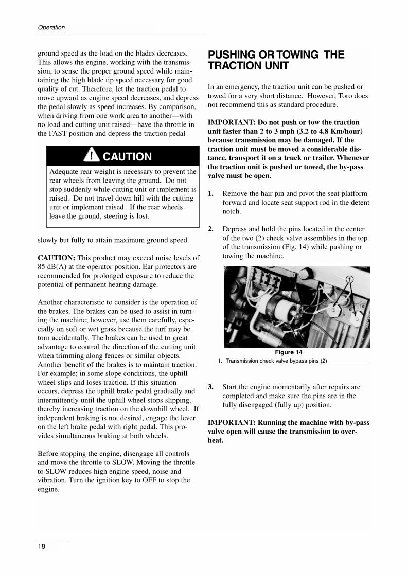
IMPORTANT: Do not push or tow the tractionunit faster than 2 to 3 mph (3.2 to 4.8 Km/hour)because transmission may be damaged. If thetraction unit must be moved a considerable dis-tance, transport it on a truck or trailer. Wheneverthe traction unit is pushed or towed, the by-passvalve must be open.
1. Remove the hair pin and pivot the seat platformforward and locate seat support rod in the detentnotch.
2. Depress and hold the pins located in the centerof the two (2) check valve assemblies in the topof the transmission (Fig. 14) while pushing ortowing the machine.
Figure 141. Transmission check valve bypass pins (2)
3. Start the engine momentarily after repairs arecompleted and make sure the pins are in thefully disengaged (fully up) position.
IMPORTANT: Running the machine with by-passvalve open will cause the transmission to over-heat.
Operation
18
Adequate rear weight is necessary to prevent therear wheels from leaving the ground. Do notstop suddenly while cutting unit or implement israised. Do not travel down hill with the cuttingunit or implement raised. If the rear wheelsleave the ground, steering is lost.
CAUTION

LUBRICATION
GREASING BEARINGS AND BUSHINGS
The traction unit has grease fittings that must belubricated regularly with No. 2 General PurposeLithium Base Grease. If the machine is operatedunder normal conditions, lubricate all bearings andbushings after every 50 hours of operation or imme-diately after every washing. Bearings and bushingsmust be lubricated daily when operating conditionsare extremely dusty and dirty. Dusty and dirty oper-ating conditions could cause dirt to get into the bear-ings and bushings, resulting in accelerated wear.
Apply a liberal coating of grease to the check valvepins once each year (Fig. 14). The traction unit hasbearings and bushings that must be lubricated, andthese lubrication points are shown in the followingfigures.
1. Wipe grease fitting clean so foreign matter can-not be forced into the bearing or bushing.
2. Pump grease into the bearing or bushing.
3. Wipe up excess grease.
Figure 15
Figure 16
Figure 17
Figure 18 (Four-Wheel Drive)
19
Maintenance

Figure 19
Figure 20 (2-Wheel Drive only)
Figure 21
Figure 22 (2-Wheel Drive only)
Maintenance
20

21
Maintenance
Quick Reference
1. Oil levels2. Coolant level3. Tire Pressure4. Belts5. Fuel—Diesel Only6. Battery7. Grease, Lube points8. Radiator screen9. Air cleaner
10. Electric clutch gap11. PTO belt tension12. Water separator
FiltersPart No.Air 277110Fuel pump 43-2550Fuel line 63-8300Transmission oil 23-2300Engine oil 67-4330
Change IntervalsFluids >0° C <0° C Capacity Fluid FilterEngine oil SAE 30 CD SAE 10W-30 CD 3.6 l 50 hours 100 hoursFuel No. 2-D No. 1-D 34 l -------- 400 hoursCoolant 50/50 mix Ethylene glycol antifreeze 6 l 2 years

Traction Unit
1. Thoroughly clean the traction unit, cutting unitand the engine, paying special attention to theseareas:
- radiator and radiator screen
- underneath the cutting unit
- under the cutting unit belt covers
- counterbalance springs
- P.T.O. Shaft Assembly
- all grease fittings and pivot points
- remove control panel and clean out the insideof the control box
- beneath seat plate and top of transmission
2. Check the tire pressure. Inflate all traction unittires to 20 psi.
3. Remove, sharpen and balance the cutting unit’sblades. Reinstall the blades and torque the bladefasteners to 85–110 ft-lb (115–149 Nm).
4. Check all fasteners for looseness; tighten as nec-essary.
5. Grease or oil all grease fittings, pivot points, andtransmission by-pass valve pins. Wipe off anyexcess lubricant.
6. Lightly sand and use touch up paint on paintedareas that are scratched, chipped or rusted.Repair any dents in the metal body.
7. Service the battery and cables as follows:
a. Remove the battery terminals from the bat-tery posts.
b. Clean the battery, terminals and posts witha wire brush and baking soda solution.
c. Coat the cable terminals and battery postswith Grafo 112X skin-over grease (ToroPart Number 505-47), or petroleum jelly toprevent corrosion.
d. Slowly recharge the battery for 24 hoursevery 60 days to prevent lead sulfation ofthe battery.
Engine
1. Drain the engine oil from the oil pan and replacethe drain plug.
2. Remove and discard the oil filter. Install a newfilter.
3. Refill the engine with 3.8 quarts (3.6 l) of rec-ommended motor oil. Refer to ChangingCrankcase Oil.
4. Start the engine and run at idle speed for twominutes.
5. Drain diesel fuel from the fuel tank, fuel lines,pump, filter and separator. Flush fuel tank withclean diesel fuel and connect all fuel lines.
6. Thoroughly clean and service the air cleanerassembly.
7. Seal the air cleaner inlet and the exhaust outletwith weather proof masking tape.
8. Check the oil filler cap and fuel tank cap toensure they are securely in place.
PRODUCT IDENTIFICATION
The traction unit has two identification numbers: amodel number and a serial number that are stampedinto a plate. The identification plate is located nearthe left brake pedal on the frame (Fig. ). In any cor-respondence concerning the traction unit, supply themodel and serial numbers to ensure correct informa-tion and replacement parts are obtained.
To order replacement parts from an AuthorizedTORO Distributor supply the following information:
1. Model and serial numbers of the traction unit.
2. Part number, description and quantity of partsdesired.
Note: Do not order by reference number if a partscatalog is being used; use the part number.
22
Preparation for Seasonal Storage

23
Maintenance
Figure 231. Model and serial ID plate