Embed Size (px)
Citation preview
Groundwater Control• Affects design of:
– Permanent Works – Temporary Works
• May affect viability of scheme • Safety Issues
– May cause instability of excavation sides and base– Additional dewatering plant must always be available in
case of breakdown
• Environmental Issues- Disposal of water removed- Lowering of local groundwater table- May cause local settlement
Hydrological Cycle
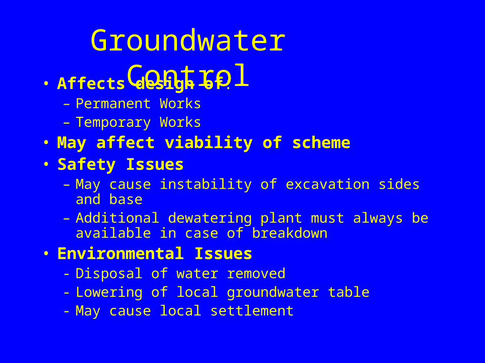
• Hydrostatic head required to force groundwater to drain to river or sea means that groundwater can be found at any elevation
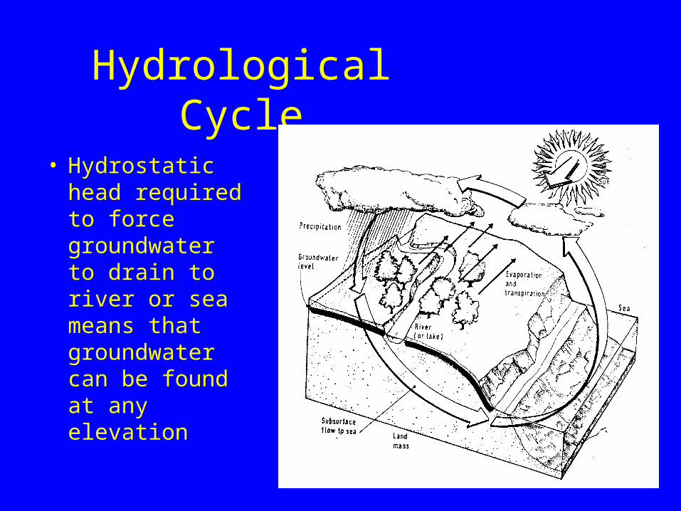
Groundwater Control
E le c tro O sm o s is
W e ll P o in ting
S u m p P u m p ing
W a terL o we ring
C o m p resse d A ir
F re e z ing
G rou ting
D ia p h rag m w a lls
B o re d P iles
S h e et P iles
W a terE xc lu s ion
M e th od
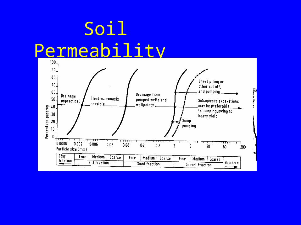
Soil Permeability
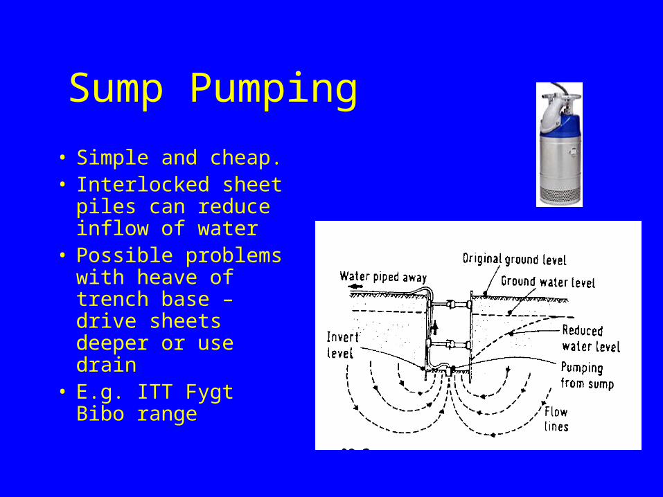
Sump Pumping
• Simple and cheap. • Interlocked sheet
piles can reduce inflow of water
• Possible problems with heave of trench base – drive sheets deeper or use drain
• E.g. ITT Fygt Bibo range

Wellpointing 1• Installed at 0.6 to 2.0 m
centres• Draws water away from
excavation• Lowers groundwater by
up to 6 M• Low volume output, not
for use in very permeable soils.
• Courtesy Andrews - Sykes
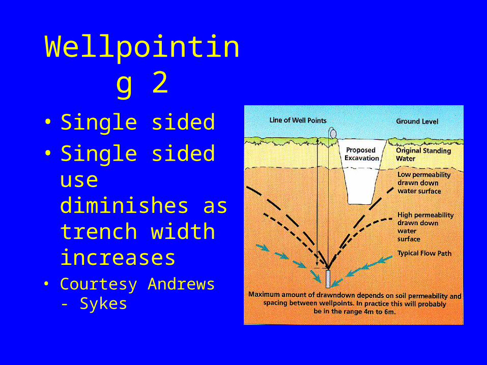
Wellpointing 2
• Single sided
• Single sided use diminishes as trench width increases
• Courtesy Andrews - Sykes
Wellpointing 3
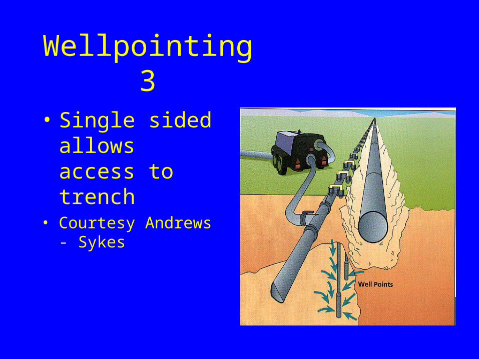
• Single sided allows access to trench
• Courtesy Andrews - Sykes
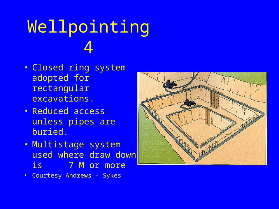
Wellpointing 4
• Closed ring system adopted for rectangular excavations.
• Reduced access unless pipes are buried.
• Multistage system used where draw down is 7 M or more
• Courtesy Andrews - Sykes
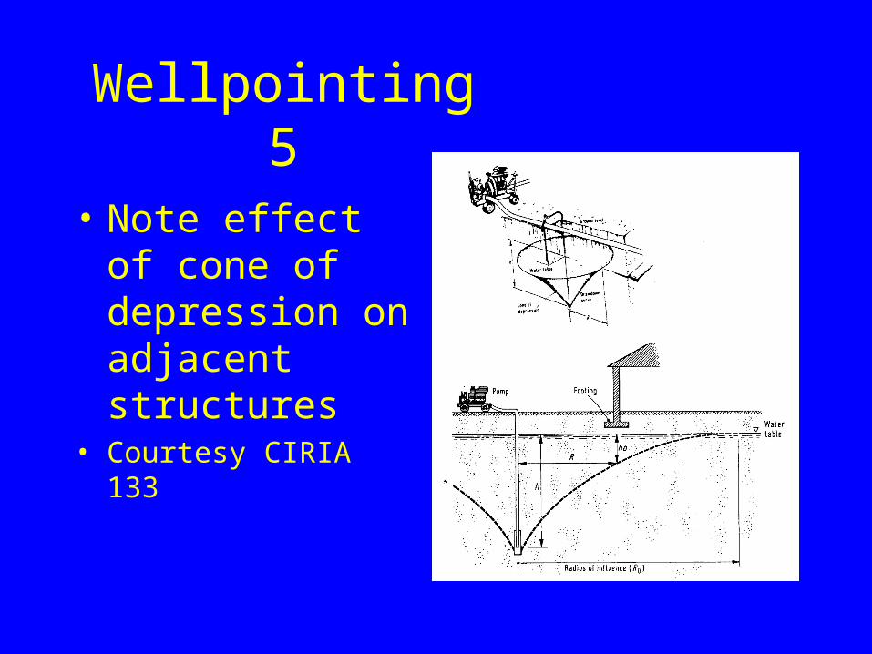
Wellpointing 5
• Note effect of cone of depression on adjacent structures
• Courtesy CIRIA 133
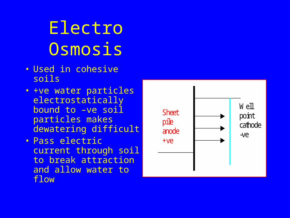
Electro Osmosis
• Used in cohesive soils• +ve water particles
electrostatically bound to –ve soil particles makes dewatering difficult
• Pass electric current through soil to break attraction and allow water to flow
Sheet pile anode +ve
Well point cathode -ve
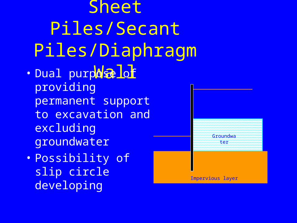
Sheet Piles/Secant Piles/Diaphragm Wall
• Dual purpose of providing permanent support to excavation and excluding groundwater
• Possibility of slip circle developing
Groundwater
Impervious layer
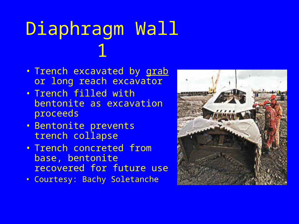
Diaphragm Wall 1
• Trench excavated by grab or long reach excavator
• Trench filled with bentonite as excavation proceeds
• Bentonite prevents trench collapse
• Trench concreted from base, bentonite recovered for future use
• Courtesy: Bachy Soletanche
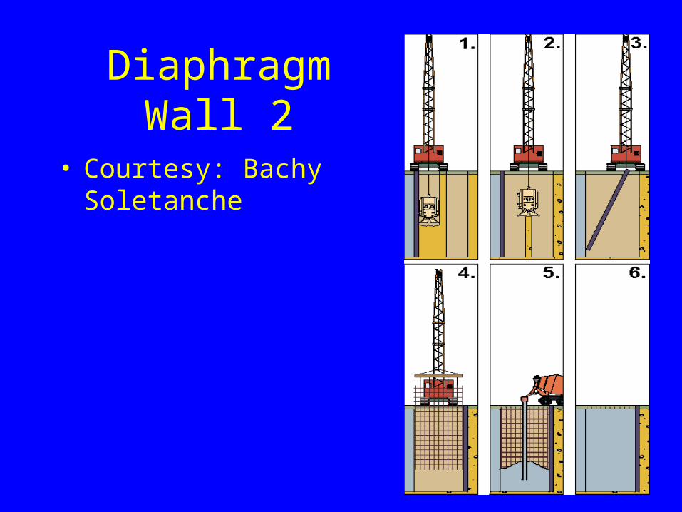
Diaphragm Wall 2
• Courtesy: Bachy Soletanche
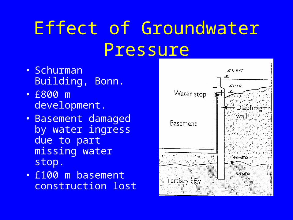
Effect of Groundwater Pressure
• Schurman Building, Bonn.
• £800 m development.• Basement damaged by
water ingress due to part missing water stop.
• £100 m basement construction lost
Grouting• Used where permeability is too high or where
access is difficult (tunnelling)• Grout is injected into the soil under pressure via
boreholes or drill holes• May be cementitious, chemical (silica based) or
bentonite• Can strengthen soil and / or form impermeable
barrier• Oldbury power station. Grouting reduced inflow
from 4500 l/min to 16 l/min
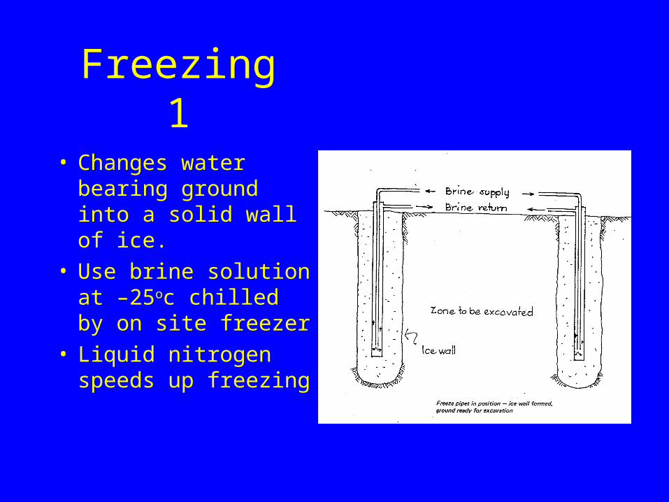
Freezing 1
• Changes water bearing ground into a solid wall of ice.
• Use brine solution at –25oc chilled by on site freezer
• Liquid nitrogen speeds up freezing
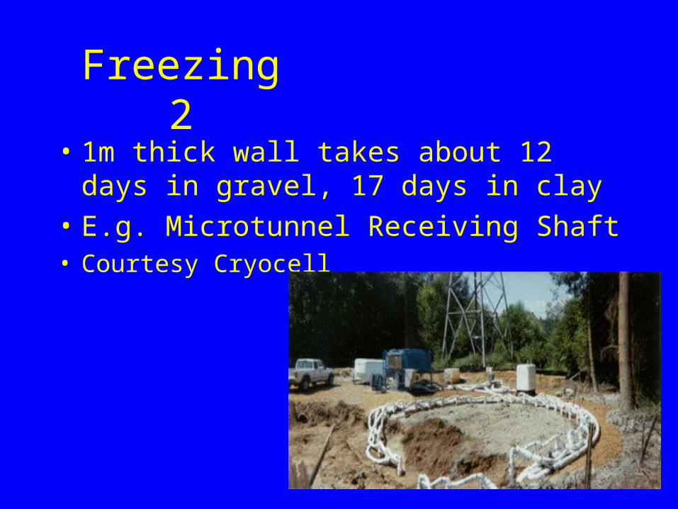
Freezing 2
• 1m thick wall takes about 12 days in gravel, 17 days in clay
• E.g. Microtunnel Receiving Shaft• Courtesy Cryocell
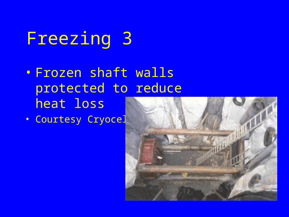
Freezing 3
• Frozen shaft walls protected to reduce heat loss
• Courtesy Cryocell