Embed Size (px)
Citation preview
Group 1: Material Testing DeviceJobe Dyson
Brie WitherspoonJohn ChandlerBrett Newstead
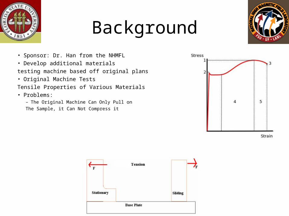
Background• Sponsor: Dr. Han from the NHMFL• Develop additional materials
testing machine based off original plans• Original Machine Tests
Tensile Properties of Various Materials • Problems:
– The Original Machine Can Only Pull on
The Sample, it Can Not Compress it
Scope
• Materials Testing Machine
• Purpose– Design Additional Materials Testing Machine Based Off of Existing Plans of
Old Machine
– New Machine Should Exert Both Tension and Compression on Sample and Be Able To Measure Those Forces
• Objective– Make Minimal Modifications To Accomplish Goal
– Increase Translational Motion; Sample Needs to Be Stretched Further
– Add Load Cell To Measure Tension Force and Compressive Force
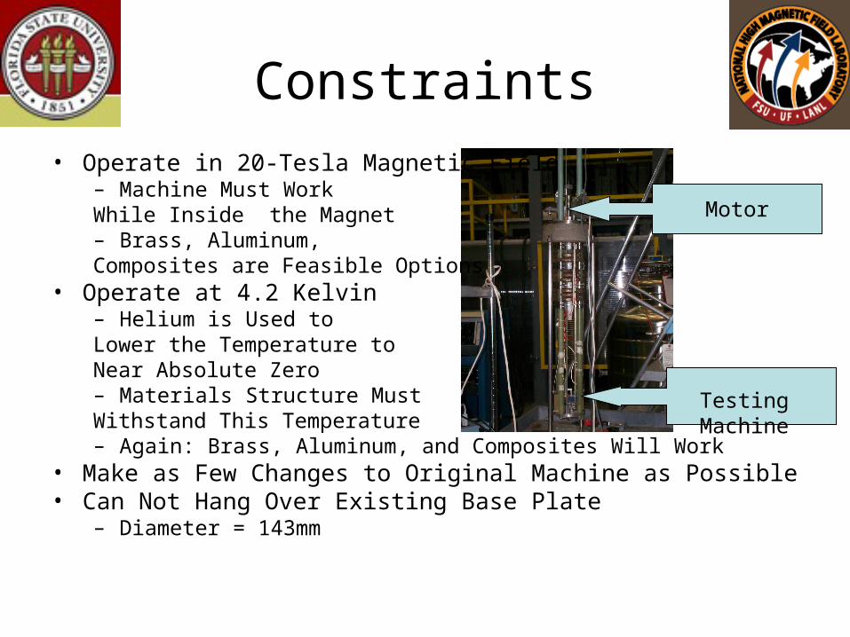
Constraints• Operate in 20-Tesla Magnetic Field
– Machine Must Work While Inside the Magnet– Brass, Aluminum, Composites are Feasible Options
• Operate at 4.2 Kelvin– Helium is Used to Lower the Temperature to Near Absolute Zero– Materials Structure Must Withstand This Temperature– Again: Brass, Aluminum, and Composites Will Work
• Make as Few Changes to Original Machine as Possible• Can Not Hang Over Existing Base Plate
– Diameter = 143mm
Testing Machine
Motor
Fall Objectives
• Create as Many Design Ideas as Possible
• Choose Final Design and Obtain Approval from Sponsor– Create Design Matrix for Final Decision
• Theoretically Test Final Design– Use FEA Program To Test Materials
• Choose Load Cell– Find a Load Cell that Meets the Criteria of the Design
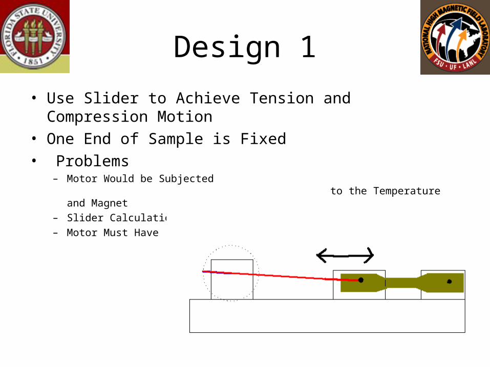
Design 1
• Use Slider to Achieve Tension and Compression Motion• One End of Sample is Fixed• Problems
– Motor Would be Subjected to the Temperature and Magnet
– Slider Calculation Must Be Extremely Specific– Motor Must Have
Enough Torque to Compress Sample
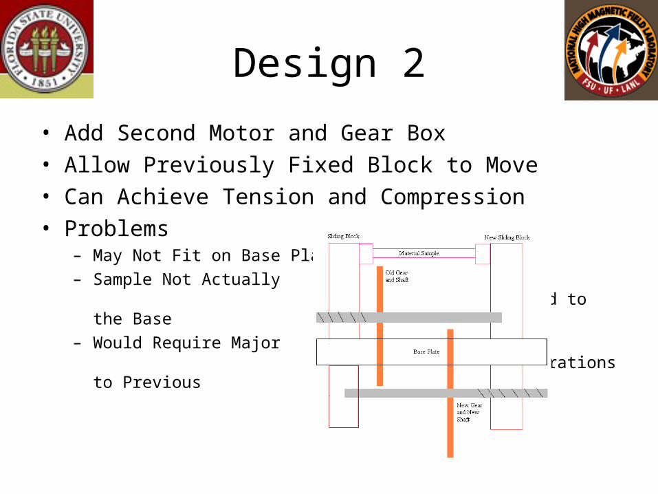
Design 2
• Add Second Motor and Gear Box• Allow Previously Fixed Block to Move• Can Achieve Tension and Compression• Problems
– May Not Fit on Base Plate
– Sample Not Actually Connected to the Base
– Would Require Major Alterations to Previous Machine
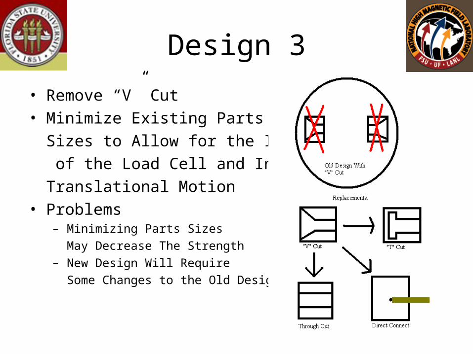
Design 3
• Remove “V” Cut• Minimize Existing Parts
Sizes to Allow for the Insertion
of the Load Cell and Increase
Translational Motion• Problems
– Minimizing Parts Sizes
May Decrease The Strength
– New Design Will Require
Some Changes to the Old Design
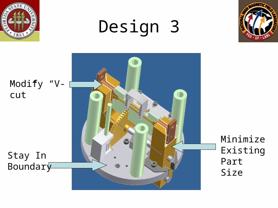
Design 3
Modify “V-cut”
Stay In Boundary
Minimize Existing Part Size
Final Choice
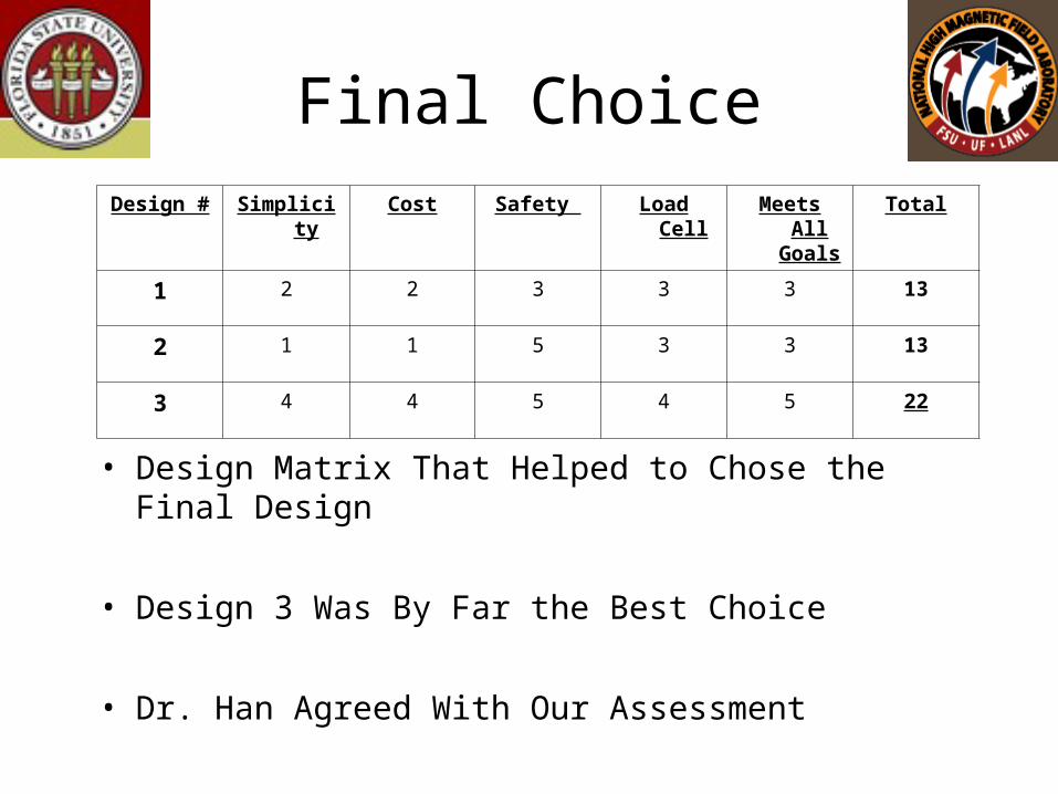
• Design Matrix That Helped to Chose the Final Design
• Design 3 Was By Far the Best Choice
• Dr. Han Agreed With Our Assessment
Design # Simplicity Cost Safety Load Cell Meets All Goals
Total
1 2 2 3 3 3 13
2 1 1 5 3 3 13
3 4 4 5 4 5 22
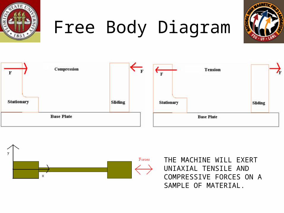
Free Body Diagram
THE MACHINE WILL EXERT UNIAXIAL TENSILE AND COMPRESSIVE FORCES ON A SAMPLE OF MATERIAL.
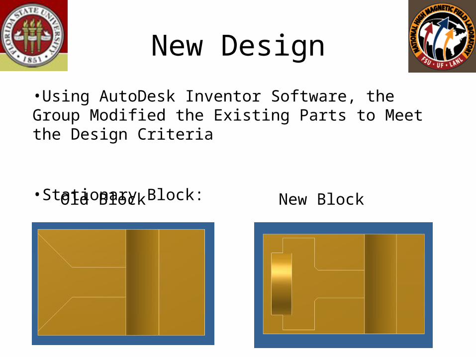
New Design
Old Block New Block
•Using AutoDesk Inventor Software, the Group Modified the Existing Parts to Meet the Design Criteria
•Stationary Block:
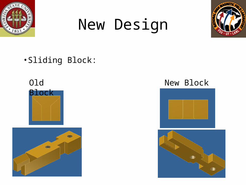
New Design
New BlockOld Block
•Sliding Block:
New Design
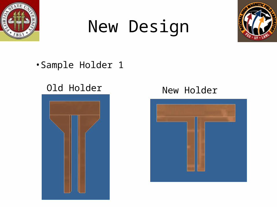
New HolderOld Holder
•Sample Holder 1
New Design
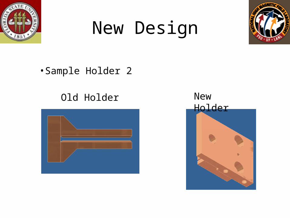
New HolderOld Holder
•Sample Holder 2
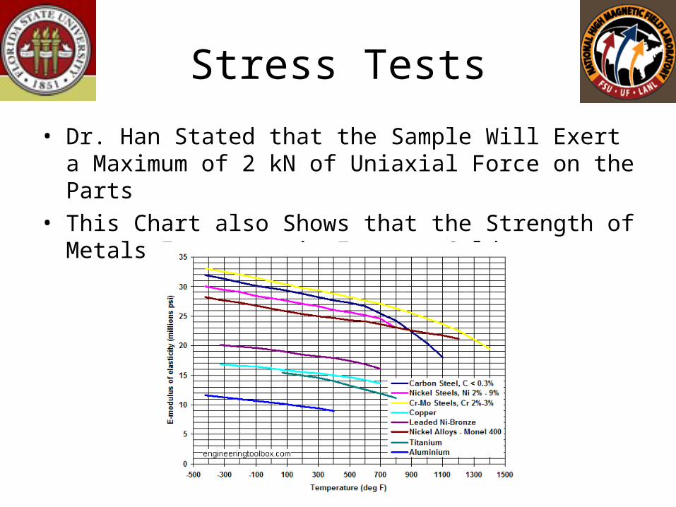
Stress Tests
• Dr. Han Stated that the Sample Will Exert a Maximum of 2 kN of Uniaxial Force on the Parts
• This Chart also Shows that the Strength of Metals Increases in Extreme Colds
Stress Tests
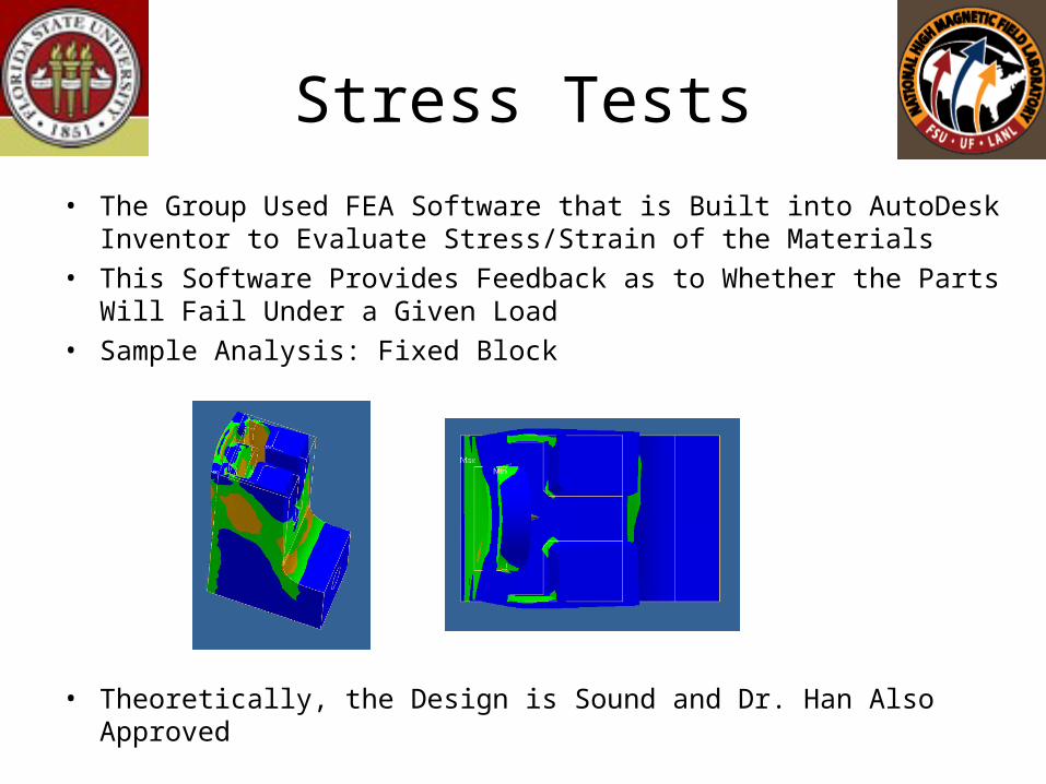
• The Group Used FEA Software that is Built into AutoDesk Inventor to Evaluate Stress/Strain of the Materials
• This Software Provides Feedback as to Whether the Parts Will Fail Under a Given Load
• Sample Analysis: Fixed Block
• Theoretically, the Design is Sound and Dr. Han Also Approved
Load Cell
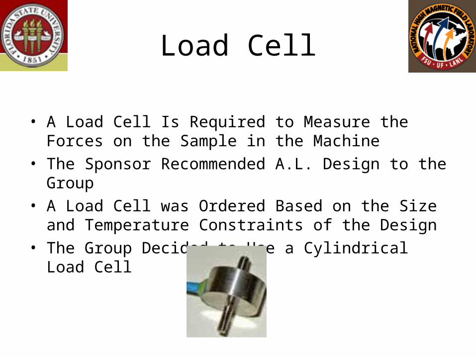
• A Load Cell Is Required to Measure the Forces on the Sample in the Machine
• The Sponsor Recommended A.L. Design to the Group• A Load Cell was Ordered Based on the Size and
Temperature Constraints of the Design• The Group Decided to Use a Cylindrical Load Cell
Spring Plan
• Submission of Final Design To Sponsor ASAP• Order Materials Needed and the Load Cell• Construct/ Assemble Parts
– Magnet Lab Machine Shop Will Help Make the Parts
– The Group will Assemble the Machine
• Configure and Test Load Cell• Test Final Assembly
– The Group Wants to Test the Machine in the Magnet
– Due to Budget/ Time Constraints, this May Not Be Possible
– At a Minimum, the Group Wants to Make Sure the Machine Responds as Expected in an Open Air Environment
Success/ Failure
• In Order For This Project To Be Considered Successful, It Must:– Fit In The Designated Cylinder– Exert Tension and Compression on Sample– Stretch Sample Further Than Previous Machine– Operate In 4.2 Kelvin and In Magnetic Field*
*This Criteria Depends on Receiving Magnet Time, and May Not Determine Overall Success.
Major Problems
• The Magnet Lab Machine Shop Was Overbooked and Unable to Work On the Group’s Project Until April
• Unable to Order All the Materials Due to a Frozen Budget
• The Load Cell Contact Fell Through, Leaving no Time to Shop for a Replacement Load Cell
• A Majority of the Parts Are Way too Complicated for the Group to Construct
Revised Spring Plan
• The Group Decided the Best Option Was to Machine the Most Critical Parts Themselves
• The Stationary and Sliding Blocks Were Determined to be the Most Critical to the Overall Design
• Dr. Han Will Obtain a Replacement Load Cell• The Group Will Use the Engineering School Machine
Shop to Make the Parts• Testing
– A Successful Test Will Require the Parts Fitting on the Existing Base Plate and the Sliding Block Moving When the Gear Turns

Testing
• The Group Was Able to Complete the Critical Parts to the Best of Their Abilities– The Machine Shop at the School did not Have the Right
Equipment to Make the More Complicated Cuts
• The Parts Fit on the Base and Moved In a Translational Motion
• Unfortunately, the Load Cell was not Able to Be Tested as a Sample Material Could Not be Attached to the Machine
• Dr. Han Considered the Design and Test a Success and Was Very Pleased With the Groups Accomplishments
Mag Lab Plan
• When They Get the Time, the Magnet Lab Will Complete the Machining of the Parts
• Theoretically, the Design Will Work as Planned• Dr. Han Will Test the Machine For:
– Increased Translational Motion– Operation in the Magnet Environment– Correct Force Exertion– Correct Operation of the Load Cell
What We Learned
• Nothing Happens as Expected• Murphy’s Law• Choose Parts Suppliers Carefully• Time Management is Crucial• You Can Not Always Get The Project as
Complete as You Want in the Time Given