Embed Size (px)
Citation preview

Peaceful Bay Pre-Feasibility Servicing Report
09109May 2010
Thompson McRobert EdgeloeGroup
Project Management Planning Geotechnical Environmental Engineering
DRAFT

DOCUMENT QUALITY CONTROL
AUTHOR DATEStuart Thompson/Rob Buller 04.05.2010
CHECKED DATEWayne Edgeloe 06.05.2010
COPYRIGHTTHIS DOCUMENT IS AND SHALL REMAIN THE PROPERTY OF THOMPSON McROBERT EDGELOE GROUP PTY LTD. THE DOCUMENT MAY ONLY BE USED FOR THE PURPOSE FOR WHICH IT WAS COMMISSIONED AND IN ACCORDANCE WITH THE TERMS OF ENGAGEMENT FOR THE COMMISSION. UNAUTHORISED USE
OF THIS DOCUMENT IN ANY FORM WHATSOEVER IS PROHIBITED.
REVISION TABLE
No. REVISION DATE
A Draft for Council Consideration 07.05.2010
THOMPSON McROBERT EDGELOE GROUP
PO BOX 733, BUNBURY
PH: (08) 9791 4411

Page i
Peaceful BayPre-Feasibility Servicing Report
CONTENTS
EXECUTIVE SUMMARY .................................................................................................................................1
1.0 Introduction .........................................................................................................................................3
2.0 Townsite Description ........................................................................................................................4
3.0 Roads ................................................................................................................................................... 10
4.0 Drainage and Groundwater ........................................................................................................ 14
6.0 Power ................................................................................................................................................... 18
7.0 Water Supply .................................................................................................................................... 19
8.0 Sewer/Non-Potable Water Supply .............................................................................................. 22
9.0 Implementation Strategy ............................................................................................................. 25
FIGURES AND TABLES
Figure 1 Location Plan 4
Figure 2 Soils and Landform 5
Table 1 Peaceful Bay Lot Yield 6
Figure 3 Aerial Photograph 7
Figure 4 Shire of Denmark Town Planning Scheme No. 3 8
Figure 5 Peaceful Bay Local Structure Plan 9
Figure 6 Road Status 11
Figure 7 Desirable Road Forms 12
Figure 8 Road Drainage Treatment 13
Figure 9 Existing Drainage 15
Figure 10 Trapezoidal drain, Bayswater, WA. Monk et al (2006) 16
Figure 11 Pipes entering lake Monger, Wembley, WA. Monk et al (2006) 16
Figure 12 Management of ARI (Average Recurrence Interval) rainfall events, Monk (2006) 16
Figure 13 Process for less than and up to 1 in 1 year ARI events, DOE (2005) 16
Figure 14 Process for greater than 1 in 1 year and up to 100 year ARI events, DOE (2005) 17
Figure 15 Treatment effi ciency for hydraulic structures in Perth, (Wong et al 1999) 17
Figure 16 Sources of Urban Water (2004/2005 water year) (Coombes et al (2007)) 19
Figure 17 Water Supply Source Options 20
Figure 18 Single Residential Water Usage, (Loh and Coghlan (2003)) 20
Figure 19 System Schematic 23

Page ii
APPENDIX 1- Water Sensitve Design Practices
1.0 WSUD Methods ..................................................................................................................................2
1.1 Gross Pollutant Traps .............................................................................................................2
1.2 Swales and Buffer Strips .......................................................................................................3
1.3 Bioretention Swales and Basins .........................................................................................5
1.4 Sedimentation Basins ...........................................................................................................7
1.5 Constructed Wetlands ..........................................................................................................9
1.6 Infi ltration Measures ........................................................................................................... 10
1.7 Sand Filters ............................................................................................................................. 11
1.8 Aquifer Storage and Recovery (ASR) ............................................................................ 12
1.9 Comparison of Methods ................................................................................................... 13
Figure 1 Pollutant size ranges for various stormwater treatment measures. Ecological Engineering (2003) 2
Figure 2 Gross Pollutant Traps- CDS Pit 3
Figure 3 Gross Pollutant Trap being cleaned 3
Figure 4 Grated lid on entry to pipe system acting as partial GPT by trapping large litter and leaf material. Lynbrook, Vic. 3
Figure 5 Grassed Swale 4
Figure 6 Grassed and Rock Swale 4
Figure 7 Rock Swale 4
Figure 8 Narrow vegetated swale 5
Figure 9 Kerb Treatment for Swale Systems, (Brisbane City Council (2006)) 5
Figure 10 Bioretention Swale Conceptual Layout 5
Figure 11 Bioretention Swale Typical Section(Brisbane City Council (2006)) 6
Figure 12 Bioretention Basin Typical Section (Brisbane City Council (2006)) 6
Figure 13 Bioretention Basin, Treendale , Australind, (TME) 6
Figure 14 Bioretention Swale at Lynbrook, Victoria. 7
Figure 15 Roadside Bioretention Garden, Wells Road, Chelsea Heights, Melbourne, (Kingston City Council (2007)) 7
Figure 16 Sedimentation Basin Conceptual Layout (Brisbane City Council (2006)) 8
Figure 17 Sedimentation Basin Key Elements (Brisbane City Council (2006)) 8
Figure 18 Temporary Sedimentation Basin, Edenbrook Estate, Queensland 8
Figure 19 Wetland Design Features, (Brisbane City Council (2006)) 9
Figure 20 Example Bathymetry of a Wetland System,(Brisbane City Council (2006)) 9
Figure 21 Infi ltration Systems, (Engineers Australia (2006)) 10
Figure 22 Boronia Ridge Stormwater Infi ltration System, DOE (2004) Chapter 9 released in 2007. 11
Figure 23 Sand Filter Schematic, (Brisbane City Council (2006)) 11
Figure 24 Components of a Well Confi gured ASR System (Brisbane City Council (2006)) 12
Figure 25 Comparison of surface areas required for each type of WSUD method. (Wong) 13
APPENDIX 2 - Rainwater Systems
1.0 Rainwater Systems ............................................................................................................................2
1.1 First Flush Diverters ...............................................................................................................4
1.2 Litter Guards .............................................................................................................................4
1.3 UV Disinfection ........................................................................................................................5
1.4 Rrainwater Tank Maintenance............................................................................................5
1.5 Water Use Reduction .............................................................................................................5
Figure 1 Proportions of Households with a Rainwater Tank, Marsden Jacob Assoc (2007) 2
Figure 2 Confi guration of Above Ground System, LHCCREMS, 2002 2
Figure 3 Confi guration of Pressure System on Below Ground System, LHCCREMS, 2002 3
Figure 4 Above Ground Rain Tanks 3
Figure 5 Below Ground Rain Tank 3
Figure 6 First Flush Diverter Operating Principles, (Rain Harvesting (2007)) 4
Figure 7 First Flush Diverter 4
Figure 8 Litter Trap 4
Figure 9 UV Disinfection System 5
Figure 10 Water Saving Appliances 5

Page 1
Peaceful BayPre-Feasibility Servicing Report
EXECUTIVE SUMMARY
The isolation and seasonal nature of household occupancy at Peaceful Bay presents unique chal-
lenges for the provision of adequate services.
This servicing report has been prepared to provide a practical servicing outcome which has a
reasonable prospect of implementation and fulfi lling the servicing requirements of the growth
identifi ed in the Peaceful Bay Local Structure Plan.
The plan provides for roads to be upgraded to a contemporary standard while still being sympa-
thetic to the local environment, and drainage upgrading to utilise water sensitive urban design
principles.
The provision of power and upgrading power supply head works is likely to present a signifi cant
barrier to future development at Peaceful Bay unless a fair, staged contributory scheme can be
established or Government assistance obtained.
The recommended power supply scheme utilises current “green power” options provided by
Western Power and also encourages use of home based photo voltaic cells to further off-set local
power demands.
Controlled subsoil drainage will need to be introduced in places to manage the water table.
A state of the art integrated water supply and effl uent disposal system is proposed for Peaceful
Bay which incorporates the following:
• Rainwater tanks to each lot to provide potable supply
• Water effi cient devices used in each home
• Sewer effl uent from each lot collected and conveyed to a treatment plant
• Effl uent treated to “Fit for Use” (class A+) standard
• Effl uent returned to each lot for non potable uses such as toilet fl ushing and garden
watering
• An operator will need to be identifi ed to be the licensed operator of sewer and non potable
systems
• Existing plantation to be cleared from site prior to development
One of the key advantages enjoyed by Peaceful Bay is the ability to overcome upfront head works
costs by freeholding existing leasehold lots in a manner which is sympathetic to existing lease-
holders. The existing sewerage load that will be generated by these houses is also an advantage
in establishing the waste water treatment plant facility.
Implementation of the recommendations of this report is a complex exercise and we strongly
encourage Council to consider appointment of a dedicated project manager to progress the
various studies and implementation strategies.
Below is the collective list of recommendations from this report:
Recommendations:
1. Preparation of a detailed road hierarchy and traffi c assessment should be prepared as part
of a full servicing report prior to further subdivision occurring at Peaceful Bay.
2. It is recommended that Groundwater monitoring be initiated in order that readings can
be taken over the next two winters and reliable data acquired for the preparation of an
District/Local Water Management Strategy and detailed design of drainage systems in
accordance with Water Sensitive Urban Design principles.
3. That Peaceful Bay adopt Water Sensitive Urban Design Practices in future stormwater
design as outlined in Appendix 1 - Water Sensitive Design Practices.
4. That an integrated sustainable power supply be pursued.
5. That the Western Power network and Infrastructure be upgraded to contemporary
standards.
6. Require the power purchased from the grid to be “Green Power”.such as “Natural Power” or
“Earth Friendly”. The natural power scheme ensures all energy is sourced from renewable
sources whereas earth friendly also provides for power supplies to be carbon neutral.
7. Utilisation of house based photo voltaic cells to provide a portion of local requirements
with any excess power generated fed back into the grid.
8. To undertake more detailed investigations into Western Power head works upgrade require-
ments and develop a mechanism to share these costs equitably across the settlement.

Page 2
9. That rainwater collection and onsite storage is the preferred option for potable water
supply for Peaceful Bay.
10. That reclaimed (recycled) water from a ERA licensed comprehensive integrated effl uent
collection, treatment and distribution scheme is the preferred non potable water supply.
11. That Council regulation is modifi ed to provide for appropriately sized water tanks.
12. That Council endorse the principle of an integrated effl uent disposal/non potable water
supply system for Peaceful Bay which allows collected rainwater to be used for potable
purposes and all effl uent being collected from each lot, taken off site for treatment and then
returned to each lot to meet non-potable water demands. The system is to have a single
licensed operator which could be the Shire of Denmark or a private Operator in which case
assets may be held by a third party and leased to the operator.
13. That the Waste Water Treatment Plant Site nominated in the Peaceful Bay Local Structure
Plan is retained and the buffer requirements reassessed when the facility is designed to a
point where risks and odour can be assessed further.
14. That Council monitor current discussions and negotiations occurring in respect to
Gracetown and Witchcliffe, each of which is currently pursuing establishment of a sewerage
and third pipe water re-use scheme similar to that described for Peaceful Bay.
15. Council should engage the services of a Project Manager to prepare a project delivery plan
and indicative project budget for the delivery of infrastructure services at Peaceful Bay. The
scope of project services should encompass but not necessarily be limited to:
• determining a fair process for privatising leasehold lots;
• entering into negotiations to deliver an integrated waste water collection, treatment and
distribution system in a manner consistent with the recommendations of this report;
• Investigate the level of government’s assistance which may be available to assist in the
project;
• progress the necessary statutory rezoning and subdivisions needed to facilitate imple-
mentation of the Peaceful Bay Structure Plan and the recommendations of this Servicing
Report;
• prepare a full feasibility analysis for the project and identify staging which will allow the
project to occur in a economically and environmentally responsible manner; and,
• to establish the extent of cost share items which all subdividers and developers will need
to contribute to and report on a mechanism which will allow this to occur.

Page 3
Peaceful BayPre-Feasibility Servicing Report
1.0 INTRODUCTION
Peaceful Bay is a seaside settlement situated in the Shire of Denmark approximately mid way
between Denmark and Walpole as shown in Figure 1. It is occupied by several full time residents
but is primarily populated for short periods during seasonal holidays
Historically the Town has been developed with a combination of leasehold and private tenure.
Approximately 205 leasehold lots, including a 130 site caravan and camping area, and 49 freehold
lots have been created. The tenure of the leasehold lots consists of Reserve 24510 being vested
in the Shire of Denmark with the power to lease and subsequent leases being issued by the Shire
for a term of 21 years. Renewal of these leases is due in July 2010, it is understood that these leases
will be issued for a further 21 years by the Shire.
Servicing of the existing settlement currently consists of a potable water supply provided by roof
top catchment and supplemented by a limited non potable reticulated supply which is operated,
and licensed to the Shire of Denmark by the Economic Regulatory Authority (ERA).
Effl uent disposal is by way of septic tanks which are in places of questionable suitability given high
water tables. Power is provided by Western Power but has little expansion capability according to
Western Power. Roads and drainage of various standards are provided by the Local Government
and while these provide a unique character, they are not at a suitable standard if permanent occu-
pation of the settlement to be pursued.
In recent years there have been proposals to expand the size of the settlement which have culmi-
nated in approval of the Peaceful Bay Local Structure Plan by Council in August 2000 and the West
Australian Planning Commission in June 2001 (subject to amendments).
The approved Structure Plan specifi cally states that further zoning, subdivision and development
of the settlement needs to be linked to the provision and upgrading of adequate urban services.
Section 21.0 Implementation of the Peaceful Bay Local Structure Plan reads ‘As a condition of sub-
division or strata titling full provision of services will be required’.
The isolation of Peaceful Bay and the limited size of the settlement pose particular servicing
issues which need to be addressed in a creative, innovative way. This study therefore attempts to
explore opportunities for servicing at Peaceful Bay which are: responsive to local needs; sensitive
to the special character that Peaceful Bay; and, enjoys and economic to pursue.

Page 4
2.0 TOWNSITE DESCRIPTION
Located approximate 50km west of the Denmark townsite (refer Figure 1 - Location Plan) Peaceful
Bay consists of land generally bound by the Walpole-Nornalup National Park to the west, Ficifolia
Road to the North, Peaceful Bay Road to the east and the Southern Ocean coastline to the South.
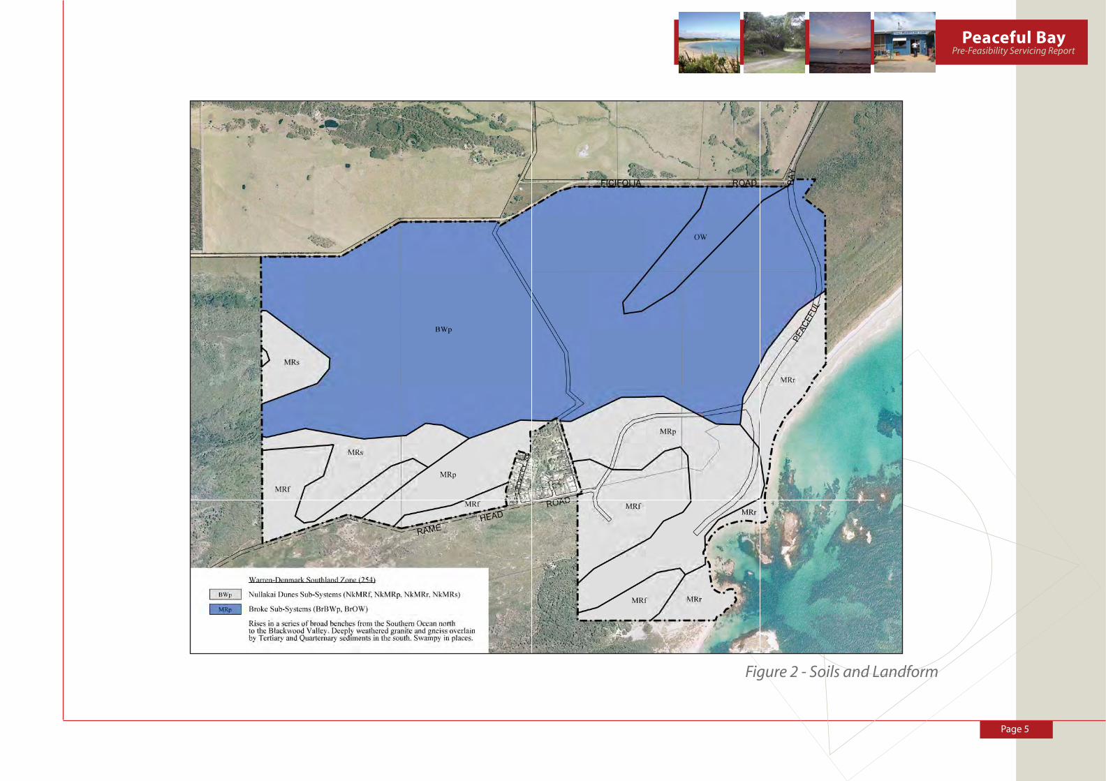
Soils and Landform
The Soil and Landform information collected as part of the Peaceful Bay Local Structure Plan
indicates that the study area is comprised of two landform units with corresponding soils. These
landforms are characteristic of coastal processes and are dominated by dune systems with various
soil profi les. They are derived from coastal aeolin (dune) or fl uvial (stream) sediments and can be
widely identifi ed in this region of the south coast, particularly from Albany through to Northcliffe
and as such are not restricted. Figure 2 – Soil and Landform Units identifi es the two landform units
present over the Peaceful Bay Structure Plan area.
Coastal Dune System
This system is known as the Meerup System and comprises a complex of parabolic dunes extend-
ing inland from the coast. They derive from windblown coastal sands and contain siliceous and
calcareous soils.
The landform is characterised by dunes with moderate slopes and interdunal swales which are
sometimes expressed as damp lands or wetlands. The dunes have suitable potential for residen-
tial development. Proposed residential development should be restricted to areas with moderate
elevation and hence satisfactory clearance to groundwater.
The Meerup coastal dune system is well represented along the South Coast.
Coastal Swampy Terrain
This land type is known as the Blackwater system and is generally seen in the lower lying north-
erly portions of the subject land. It represents a more eroded, older and less defi ned landform. This
unit comprises a fl at to undulating plain with poor, diffuse drainage patterns, with some wetlands
and linear dunes. The elevation ranges from 12-30metres AHD, rising in the north-west. These
sub-coastal linear dunes are sparsely to moderately vegetated while the lower lying soils can have
denser wetland vegetation types varying from sedge lands to woodlands. The Blackwater system
is well represented in this region of the south coast.
Vegetation
The remnant vegetation within the Structure Plan is generally refl ects the landform units above
and is also widely spread along the southern coast. The vegetation is heavily represented within
the National Parks and reserves along this portion of the south coast including the adjacent
areas.
Figure 1 - Location Plan
Page 5
Peaceful BayPre-Feasibility Servicing Report
Figure 2 - Soils and Landform

Page 6
The structure plan area contains a large amount of remnant vegetation. The condition of the veg-
etation varies depending on the landuse associated with the present and historic use of land. The
camping and recreation reserve 24510 comprises largely undisturbed vegetation in the northern
portion, notwithstanding the landfi ll site in the north-east corner. Lot 1425 comprises blue gum
plantations on the northern portion and remnant vegetation in the southern portion which has
suffered impacts in the past due to grazing. Vegetation on lot 301 comprises portions of cleared
land, improved pasture, in the north and south edges, with grazed remnant vegetation on the
balance of the land.
The physical and fl ora characteristics of the subject land provide development and conservation
options which are refl ected in the Structure Plan. There is potential during development to retain
stands of remnant vegetation for aesthetic and planning purposes. It should be noted that while
these associations may be signifi cant remnant vegetation, they do not necessarily have a high
conservation status.
Existing Development
The existing development within the Peaceful Bay precinct consists of approximately 49 freehold
lots (of which approximately 2/3 are developed) and 205 leasehold sites and a 130 site caravan
park site. The settlement also contains several community purpose buildings. The majority of the
leasehold buildings were developed in the 1950’s and 60’s and only a few dwellings have been
constructed since this time. The townsite consists of a small number of permanent residents with
most of the developed area being short-stay holiday accommodation.
The Shire of Denmark Town Planning Scheme No. 3 depicted in Figure 4 includes several zoning
classifi cations, these being; “Parks and Recreation” (lots 1422, 1423 and 1424), “Residential” (central
triangle) and “Rural” (lots 301 and 1425).
The area of land zoned for residential development is largely developed, with very limited area
identifi ed for future expansion.
Future Development Opportunities
Future development opportunities for the Peaceful Bay area are mostly dependant on the avail-
ability and upgrading of services, access to the area and approvals to clear some of the land.
The Peaceful Bay Local Structure Plan indicates that approximately 430 additional lots could be
created. The density of development proposed resonds top the extent of remnant vegetation.
The less vegetated areas are proposed for village settlement with the more vegetated areas being
identifi ed for rural residential, landscape protection area and conservation lots.
Future development is proposed within the ‘Rural’ zoned lots with the balance of the land identi-
fi ed for conservation and National Park reservation.
Table 1 indicates the lot yield of existing and proposed development identifi ed in the Peaceful Bay
Structure Plan
Leasehold
Lots
Freehold
Lots
Caravan Park
Sites
Total Development
Existing 205 49 130
Proposed 435
Total 205 484 130 819
Table 1 - Peaceful Bay Lot Yield
Page 7
Peaceful BayPre-Feasibility Servicing Report
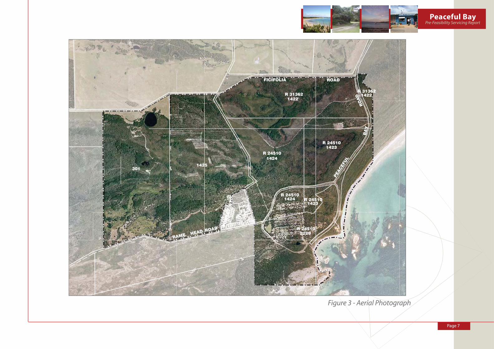
Figure 3 - Aerial Photograph

Page 8
Figure 4 - Shire of Denmark Town Planning Scheme No. 3
PEACEFUL BAY LOCALITY
R5
R10
R10R5R10
T2 PEACEFUL BAY LOCALITYRefer to Map
6
Map 6 Enlargement
Subject Land

Page 9
Peaceful BayPre-Feasibility Servicing Report
Figure 5 - Peaceful Bay Local Structure Plan
Page 10
3.0 ROADS
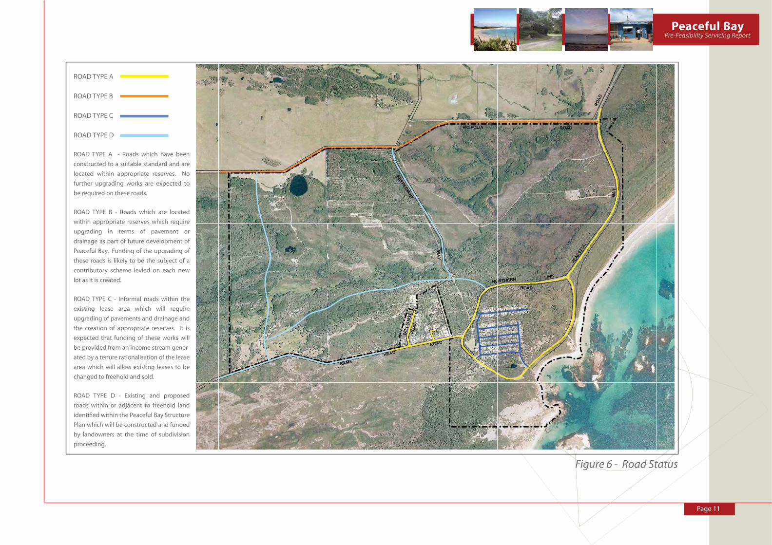
Figure 6 – Road Status highlights the key considerations with respect to roads within the study
area.
Roads generally fall within the following classifi cations:-
• ROAD TYPE A - Roads which have been constructed to a suitable standard and are located
within appropriate reserves. No further upgrading works are expected to be required on
these roads.
• ROAD TYPE B - Roads which are located within appropriate reserves which require upgrad-
ing in terms of pavement or drainage as part of future development of Peaceful Bay. Funding
of the upgrading of these roads is likely to be the subject of a contributory scheme levied
on each new lot as it is created.
• ROAD TYPE C - Informal roads within the existing lease area which will require upgrading
of pavements and drainage and the creation of appropriate reserves. It is expected that
funding of these works will be provided from an income stream generated by a tenure
rationalisation of the lease area which will allow existing leases to be changed to freehold
and sold.
• ROAD TYPE D - Existing and proposed roads within or adjacent to freehold land identifi ed
within the Peaceful Bay Structure Plan which will be constructed and funded by landown-
ers at the time of subdivision proceeding.
Principals of Road Construction
All future roads and road upgrading will be designed to serve the following functions:-
1. Provide legal access to each lot;
2. Provide emergency service access;
3. Provide a network of linkages within the settlement;
4. To provide a 100 year over-land fl ow path for storm water in major events;
5. To be responsive to the unique character of Peaceful Bay;
6. Achieve water sensitive urban design principals;
7. Enhance landscape improvement opportunities along road verges;
8. Aid in the collection of stormwater for treatment to supplement the water supply;
The width of road pavements is generally anticipated to be 6 meters or less, sealed with either
fl ush or mountable kerbs. Figure 7 – Road Forms below depicts road forms which are considered
suitable for Peaceful Bay.
Road Drainage will need to adopt water sensitive urban design principles. Flush or channel kerbed
roads are preferred with swales or bio retention gardens as shown in Figure 8 - Road Drainage
Treatment.
Where swales are used they should incorporate native plants and rock mulch in order that sup-
plementary watering is not required.
Recommendation:
1. Preparation of a detailed road hierarchy and traffi c assessment should be prepared as part
of a full servicing report prior to further subdivision occurring at Peaceful Bay.
Page 11
Peaceful BayPre-Feasibility Servicing Report
Figure 6 - Road Status
ROAD TYPE A
ROAD TYPE B
ROAD TYPE C
ROAD TYPE D
ROAD TYPE A - Roads which have been
constructed to a suitable standard and are
located within appropriate reserves. No
further upgrading works are expected to
be required on these roads.
ROAD TYPE B - Roads which are located
within appropriate reserves which require
upgrading in terms of pavement or
drainage as part of future development of
Peaceful Bay. Funding of the upgrading of
these roads is likely to be the subject of a
contributory scheme levied on each new
lot as it is created.
ROAD TYPE C - Informal roads within the
existing lease area which will require
upgrading of pavements and drainage and
the creation of appropriate reserves. It is
expected that funding of these works will
be provided from an income stream gener-
ated by a tenure rationalisation of the lease
area which will allow existing leases to be
changed to freehold and sold.
ROAD TYPE D - Existing and proposed
roads within or adjacent to freehold land
identifi ed within the Peaceful Bay Structure
Plan which will be constructed and funded
by landowners at the time of subdivision
proceeding.

Page 12
Figure 7 – Desirable Road Forms

Page 13
Peaceful BayPre-Feasibility Servicing Report
Figure 8 - Road Drainage Treatment

Page 14
4.0 DRAINAGE AND GROUNDWATER
Figure 9 – Existing Drainage depicts an indicative drainage catchment network for the study area
and where major infl ows are expected.
Drainage at Peaceful Bay is further complicated by a high water table and there is evidence that
septic tanks are at times inundated by the water table generating a potential health risk.
The ability to provide further advice in respect to drainage and groundwater is limited by the
absence of long term, reliable monitoring of groundwater levels which could eventually be used
to prepare a District/Local Water Management Strategy. This would support rezoning of the
land.
In addition, an Urban Water Management Plan would be required for each landholding at subdivi-
sion stage.
Recommendation:
2. It is recommended that Groundwater monitoring be initiated in order that readings can
be taken over the next two winters and reliable data acquired for the preparation of an
District/Local Water Management Strategy and detailed design of drainage systems in
accordance with Water Sensitive Urban Design principles.
Water Sensitive Urban Design
Water Sensitive Urban Design (WSUD) is an internationally recognised concept that offers an
alternative to traditional development practices. WSUD is a holistic approach to the planning and
design of urban development that aims to minimise negative impacts on the natural water cycle
and protect the health of aquatic ecosystems. It promotes the integration of stormwater, water
supply and sewage management at a broad scale.
WSUD represents a fundamental change in the way urban development is conceived, planned,
designed and built. Rather than using traditional approaches to impose a single form of urban
development across all locations, WSUD considers ways in which urban infrastructure and the
built form can be integrated with a site’s natural features. In addition, WSUD seeks to optimise the
use of water as a resource.
The key principles of WSUD are to:
• Protect existing natural features and ecological processes.
• Maintain the natural hydrological behaviour of catchments.
• Protect water quality of surface and ground waters.
• Minimise demand on the reticulated water supply system.
• Minimise sewage discharges to the natural environment.
• Integrate water into the landscape to enhance visual, social, cultural and ecological values.
WSUD has evolved over recent years and many advances have been made in the fi eld. WSUD
is now well established in developments and guidelines are available from the Department of
Water.
In order to understand the fundamental differences between the traditional approach to drainage
and WSUD the following comparison is provided.
Traditional Drainage Design
Traditionally developments have been created and stormwater systems developed such that:
• Almost all native vegetation on site is cleared;
• Major earthworks are undertaken such that cut is taken from hill tops to fi ll low lying land
(usually wetlands);
• Large areas of impervious surfaces are created;
• Large pipe and channel systems are built to rapidly convey stormwater to outlet;
• Large sumps or wetlands are constructed at the at bottom end of systems; and,
• Little respect for natural systems and processes.
These are demonstrated in Figures 10 and 11 ( Monk et al (2006)) where very harsh, engineered
systems have been installed as part of the stormwater system

Page 15
Peaceful BayPre-Feasibility Servicing Report
Figure 9 - Existing Drainage
FLOW DIRECTION
WETLAND &
VEGETATION
POND
WETLAND

Page 16
These systems cause signifi cant changes to catchment hydrology and characteristics of the
stormwater. They were generally developed to effi ciently convey and dispose of stormwater for
fl ood protection with little consideration given to the treatment of stormwater. They were also
generally designed to control or lower groundwater levels to allow development to proceed.
This traditional approach is an environmentally insensitive solution which leads to hard engineer-
ing solutions and is not considered desirable.
Water Sensitive Approach
The Water Sensitive Approach to drainage design as described by Monk et al (2006) includes:
• Mimicking natural processes;
• Managing stormwater quality;
• Predevelopment peak fl ows to match post development peaks;
• Retention of natural vegetation;
• Sustainable solutions;
• Maximising onsite retention/ detention of stormwater;
• Recognising that designing a system for 1 year events that can cater for in excess of 99% of
all storm events; and
• Designing for 1 in 1 year peak storm for water quality treatment
The management of the various stormwater events using WSUD is depicted in Figure 12 -
Management of 0 to 100 year ARI Events.
Figure 12 - Management of ARI (Average Recurrence Interval) rainfall events, Monk (2006)
These principles are fi rmly embedded in Department of Water, DOE Policy (2005) and the approval
process for Stormwater management in WA.
Principles for up to 1 Year ARI Events
For the small events up to and including the 1 in 1 year ARI event, the guidelines state, DOE
(2005):
Figure 13 - Process for less than and up to 1 in 1 year ARI events, DOE (2005)
Figure 10 - Trapezoidal drain, Bayswater, WA.
Monk et al (2006)
Figure 11 - Pipes entering lake Monger, Wembley, WA.
Monk et al (2006)
Page 17
Peaceful BayPre-Feasibility Servicing Report
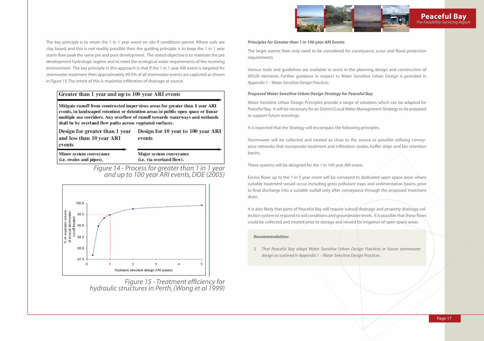
The key principle is to retain the 1 in 1 year event on site if conditions permit. Where soils are
clay based, and this is not readily possible then the guiding principle is to keep the 1 in 1 year
storm fl ow peak the same pre and post development. The stated objective is to maintain the pre
development hydrologic regime and to meet the ecological water requirements of the receiving
environment. The key principle in this approach is that if the 1 in 1 year ARI event is targeted for
stormwater treatment then approximately 99.5% of all stormwater events are captured as shown
in Figure 15. The intent of this is maximise infi ltration of drainage at source.
Figure 14 - Process for greater than 1 in 1 year
and up to 100 year ARI events, DOE (2005)
Figure 15 - Treatment effi ciency for hydraulic structures in Perth, (Wong et al 1999)
Principles for Greater than 1 in 100 yaer ARI Events
The larger events then only need to be considered for conveyance, scour and fl ood protection
requirements.
Various tools and guidelines are available to assist in the planning, design and construction of
WSUD elements. Further guidance in respect to Water Sensitive Urban Design is provided in
Appendix 1 – Water Sensitive Design Practices.
Proposed Water Sensitive Urban Design Strategy for Peaceful Bay
Water Sensitive Urban Design Principles provide a range of solutions which can be adapted for
Peaceful Bay. It will be necessary for an District/Local Water Management Strategy to be prepared
to support future rezonings.
It is expected that the Strategy will encompass the following principles.
Stormwater will be collected and treated as close to the source as possible utilising convey-
ance networks that incorporate treatment and infi ltration swales, buffer strips and bio retention
basins.
These systems will be designed for the 1 in 100 year ARI event.
Excess fl ows up to the 1 in 5 year event will be conveyed to dedicated open space areas where
suitable treatment would occur, including gross pollutant traps and sedimentation basins, prior
to fi nal discharge into a suitable outfall only after conveyance through the proposed treatment
drain.
It is also likely that parts of Peaceful Bay will require subsoil drainage and property drainage col-
lection system to respond to soil conditions and groundwater levels. It is possible that these fl ows
could be collected and treated prior to storage and reused for irrigation of open space areas.
Recommendation:
3. That Peaceful Bay adopt Water Sensitive Urban Design Practices in future stormwater
design as outlined in Appendix 1 – Water Sensitive Design Practices.

Page 18
6.0 POWER
Power is currently conveyed to Peaceful Bay by a 3 phase 22kv power line utilising the align-
ment of Pioneer Road from the Coastal Highway intersection with Peaceful Bay Road. This supply
services the Peaceful Bay town site and tourist area. A single phase power line runs from the
Pioneer Road/Ficifolia Road intersection to a farm residence situated 900 metres to the West
along Ficifolia Road.
Western Power advise that the current power supply has the capacity to supply an estimated
additional 55 dwellings in increments of 15 dwellings before upgrading is required.
In order to supply the planned expansion of Peaceful Bay, as outlined in the Peaceful Bay Structure
Plan, it is likely that an increase in supply head works consisting of 8 drop out fuse connections,
37 transformers plus earthing and cables will be required. This would be at an approximate cost
of $1, 540, 000.
The cables and pillars to serve the lots is estimated at $4, 500 per lot resulting in an estimated cost
to the development of about $1, 876. 500.
Additional power supplies at Peaceful Bay will be classifi ed as edge of grid by Western Power,
and therefore will be at the full cost of subdividers. Indicative research suggests that these costs
could be in the order of $2, 316, 000 dollars and therefore represent a signifi cant barrier to future
development.
In the absence of a Government contribution to the provision of the necessary power head works,
the most practical approach is to develop a mechanism which will allow proportional contribu-
tions to head works to be made by each of the developers at Peaceful Bay.
Options for the Provision of Alternative Power
Recent investigations into alternative power schemes for Gracetown have evaluated wind, solar,
wave and local diesel generators. Detailed evaluation of these options has not occurred for
Peaceful Bay however the following conclusions and observations are relevant.
The use of photo voltaic cells has been found to be particularly appropriate in holiday settle-
ments where houses may be empty for extended periods of time. In these instances, almost all
of a homes needs can be generated by photo voltaic cells, but these need to be connected to a
wider supply grid so that generated power can be utilised in off peak times. In addition it needs to
be recognised that as latitude increases the effi ciency of solar cells decreases. There is a question
about the effi ciency of solar cells as far south as Peaceful Bay.
Wave power generation has been seriously considered as part of the Gracetown project and it
appears that the technology is well developed but more suited to larger settlements. There is no
Western Australian proven wave generation technology suitable for Peaceful Bay.
Wind power generation technology is well developed and used throughout the State. Research
shows that turbine generation is most effi cient when turbines are located where wind regimes
are reliable over an extended period. It is also true that wind power generation needs to be part
of a wider power network to cover those times when turbines are not generating. The solution at
both Gracetown and Witchcliffe is to purchase Green Power from Western Power. There is the pos-
sibility to put in a turbine to offset the power used by a local reclaimed water treatment facility as
a token to local sustainability however the current most sustainable power supply is the purchase
of Green Power from Western Power to allow renewable energy to be generated in the most
effi cient locations.
Recommendations:
4. That an integrated sustainable power supply be pursued.
5. That the Western Power network and Infrastructure be upgraded to contemporary
standards.
6. Require the power purchased from the grid to be “Green Power”.such as “Natural Power” or
“Earth Friendly”. The natural power scheme ensures all energy is sourced from renewable
sources whereas earth friendly also provides for power supplies to be carbon neutral.
7. Utilisation of house based photo voltaic cells to provide a portion of local requirements
with any excess power generated fed back into the grid.
8. To undertake more detailed investigations into Western Power head works upgrade require-
ments and develop a mechanism to share these costs equitably across the settlement.

Page 19
Peaceful BayPre-Feasibility Servicing Report
7.0 WATER SUPPLY
Existing Water Supply
The existing water supply for Peaceful Bay consists of roof top catchment for potable purposes
and either roof top catchment, groundwater extraction and/or access to a licenced non-potable
water supply scheme operated by the Shire.
Roof top catchment and storage is utilised on all properties for potable purposes although not all
sites utilise water tanks with a capacity of 92,000 litres which is the generally accepted standard
in the South West of the state.
A non-potable water supply scheme is connected to the 203 lease sites and the caravan park.
This non potable supply is operated by and licensed to the Shire of Denmark by the Economic
Regulatory Authority. The Scheme is sourced from a pond situated adjacent to the general store.
The pond is topped up from a bore located within the Walpole-Nornalup National Park approxi-
mately 7km’s from the settlement. Water from the pond is pumped into two 54kilolitre holding
tanks located on an elevated position behind the General Store and then gravity fed to both the
leasehold lots and the Caravan Park.
Water supplied to the caravan park undergoes disinfection (chlorination) via an automated process
prior to being pumped into the designated storage tank for caravan park use only. The water for
use within the leasehold lots does not undergo any form of treatment and is not intended for
human consumption. It is deemed a non potable supply. It is a condition of leases that each
dwelling construct and maintain a potable storage tank which has a capacity of at least 4,640
litres of groundwater. It is intended and assumed that rainwater is used to fi ll these tanks and be
used as the potable source for the leasehold dwellings.
Potable Water Supply Context
In W.A. there are 3 main suppliers of drinking water. These are:
• Licensed public drinking water suppliers such as the Water Corporation, Aqwest or Busselton
Water Board.
• Privately owned small water systems supplying the public e.g. roadhouses and caravan
parks
• Private domestic water supplies.
The source of potable water for each of these suppliers is varied and includes:
• Surface water dams, rivers and soaks
• Groundwater from bores and springs
• Rainwater
• Desalinated seawater or brackish water
Figure 16 - Sources of Urban Water (2004/2005 water year) (Coombes et al (2007))
On an Australian wide basis it can be seen in Figure 16 – Sources of Urban Water (2004/2005 water
year) that the majority of the potable water supplies are sourced from dams and ground water
and that alternate supplies are still very low. This is also the case in Western Australia.
Approximately 90% of Western Australians are supplied from licensed and regulated water supply
schemes. (Department of Health, 2001). In other states however the provision of water from self
controlled supplies is more varied.
In Western Australia the Department of Health controls drinking water in public supplies and
applies the recommendations of the Australian National Drinking Water Guidelines. All public
water suppliers in Western Australia are also required to be licensed by the Economic Regulatory
Authority (ERA). Individual households with their own rainwater tanks, dams or bores are not
required to be licensed.

Page 20
Water Supply Options for Peaceful Bay
It is an objective of this report to explore alternative water supplies for Peaceful Bay and not rely
on conventional methods.
The range of possible supplies is shown in Figure 17 –Water Supply Source Options.
Figure 17 - Water Supply Source Options
The most conventional option would be to extend or create a Water Corporation supply similar to
the options discussed in the Nilson Projects 2003 study commissioned by the Water Corporation
titled “Peaceful Bay Desktop Study into Water and Wastewater Services”. This report explored
several contemporary supply options most of which are prohibitively expensive and do nothing
to develop a local sustainable water supply for Peaceful Bay.
The second option is to utilise the roof runoff generated on each lot and to use this water for
in-house potable water demands such as:
• Drinking water
• Kitchen use
• Laundry use
• Showering and washing
This option is partly in place now and is the preferred option from a sustainable perspective. This
option is further detailed later in this report.
Stormwater can also be a possible water supply source but not currently for potable water
demands. Its use for non potable water is acceptable providing treatment occurs to the correct
levels.
The remaining water supply options utilise the waste water stream consisting of:
• Light grey water
• Grey water
• Black water
Each of these sources requires varying levels of treatment but cannot be used as a source of
potable or drinking water.
Finally, is the possibility of utilising groundwater as a potable source. The Nilson Projects 2003
report suggests that there is a sustainable groundwater supply but the preferred location of bores
is within an established National Park and environmental issues may make obtaining approvals
diffi cult.
Potable and Non Potable Water Demand
The average Australian family uses between 250,000 and 300,000 litres of water per year.
This water is used inside and outside the household with approximately 54% of water in Western
Australia being used for watering outside the
household. This is shown in Figure 18 – Single
Residential Household Usage. Loh and Coghlan
(2003).
Figure 18 - Single Residential Water Usage,
(Loh and Coghlan (2003))

Page 21
Peaceful BayPre-Feasibility Servicing Report
Adding the 9% toilet usage to the 54% garden usage, approximately 63% of water usage is in
areas where a non potable supply would suffi ce. The balance of 37% of the supply then only need
be to a potable supply standard.
We therefore propose that the Peaceful Bay potable supply be obtained by rooftop catchment of
rainwater and utilisation of storage tanks on each residence.
The design options and standards for rainwater collection and storage systems are provided in
Appendix 2 – Rainwater Systems
Potable Water Supply Regulatory Framework
It is proposed that each lot provide its own potable water supply via rainwater capture and storage
systems. These systems will be fully owned by each landowner and thus the operation and main-
tenance of these will be fully the landowner’s responsibility. As long as the roof areas that feed the
system are not shared between different owners, then the responsibilities are relatively straight
forward.
The Shire currently require a minimum of 92,000 litres of storage where rain tanks are used except
in the leasehold area where 4,640 litre tanks are a lease requirement and the supply is supple-
mented by reticulated non potable supply.
There may be a need from Council to reduce the 92,000 litre standard if water reuse is part of
the ultimate reuse system, although larger tanks do provide a higher level of security to cover
abnormal demands on low rainfall years.
No specifi c regulations apply to rain tanks other than the requirement for a building license from
the Local Authority at construction stage.
Recommendations
9. That rainwater collection and onsite storage is the preferred option for potable water
supply for Peaceful Bay.
10. That reclaimed (recycled) water from a ERA licensed comprehensive integrated effl uent
disposal collection, treatment and distribution scheme is the preferred non potable water
supply.
11. That Council regulation is modifi ed to provide for appropriately sized water tanks.

Page 22
8.0 SEWER/NON-POTABLE WATER SUPPLY
Existing Effl uent Systems
At present all existing houses at Peaceful Bay have their own onsite effl uent disposal systems.
There is anecdotal evidence that the high water table in some areas leads to the potential for
contamination of the groundwater.
In addition, there is no operational sewerage scheme within the vicinity and therefore any com-
prehensive sewerage collection and treatment system will need to be stand alone and locally
based. Peaceful Bay is not currently within a Economic Regulatory Authority (ERA) Licensed
Sewerage scheme area.
More importantly, there is a local desire for an alternative servicing scheme which is more envi-
ronmentally sound and sustainable.
Effl uent Disposal Options
There is a range of possible effl uent collection and disposal options for Peaceful Bay.
The simplest system to manage is to collect all effl uent from each lot and convey it to a sewer treat-
ment plant within the vicinity of Peaceful Bay. This plant and associated collection system would
need a licensed operator that meets the requirements of the Economic Regulatory Authority.
The second option is to collect the effl uent and treat it on each individual lot. This option is dif-
fi cult to implement given the inability of soils at Peaceful Bay to adequately treat effl uent and the
high groundwater levels which are encountered.
A further option is to collect and re-use the grey water generated by each site and then export the
excess grey water and black water off site. In this solution each lot owner is required to maintain
a suitable treatment mechanism for grey water. This option has major constraints associated with
health and maintenance issues and there is still a requirement for a licensed provider to operate
the off site collection and disposal system.
Preferred Peaceful Bay Effl uent Disposal System
The preferred system for Peaceful Bay is for all effl uent to be collected from each lot, taken off site
for treatment and then returned to each lot to meet non-potable water demands. This solution
provides for a single licensed operator and allows collected rainwater to be initially used for
potable purposes, subsequently treated and returned to each household for non-potable uses.
The re-use of water means that the volume of water necessary to be held at each house is sub-
stantially reduced. In addition, issues of ongoing maintenance of onsite disposal systems and
responding to high groundwater levels are overcome. The catchment area of roofs will need to be
determined through an assessment of rainfall statistics and trends to ensure adequate water is
collected for a range of occupancies and climate conditions.
The non-potable water supply would be treated to “Fit for Purpose” standards (previously known
as class A+) based on the National Guidelines for Water Recycling which were developed by the
Natural Resource Management Ministerial Council and the Environment Protection and Heritage
Council (2006).
It is expected that the treated water at Peaceful Bay would be utilised for:-
• Toilet fl ushing;
• Garden watering;
• Fire fi ghting;
• Unrestricted Irrigation of open space areas.
Treated water is suitable for use in washing machines but it is possible there could be an initial
public resistance to this and so it should not be planned in the initial instance. As the public
becomes more knowledgeable about the use of recycled non-potable water, and associated risks,
the option to have houses plumbed to allow for treated water to be used in washing machines
could be explored further.
The Peaceful Bay treatment system would be expected to be owned and operated by a single
licensed service provider. This provider would own and operate:-
• The sewer collection system;
• The sewer treatment plant;
• The non-potable water distribution system.
The provider would charge each lot owner an appropriate annual fee and consumption charges
for sewer collection and non-potable water supply.
Page 23
Peaceful BayPre-Feasibility Servicing Report
This Report does not make a recommendation as to who is an appropriate service provider.
Providers could be:-
• Shire of Denmark;
• Water Corporation;
• A private Operator in which case assets may be held by a third party and leased to the
operator.
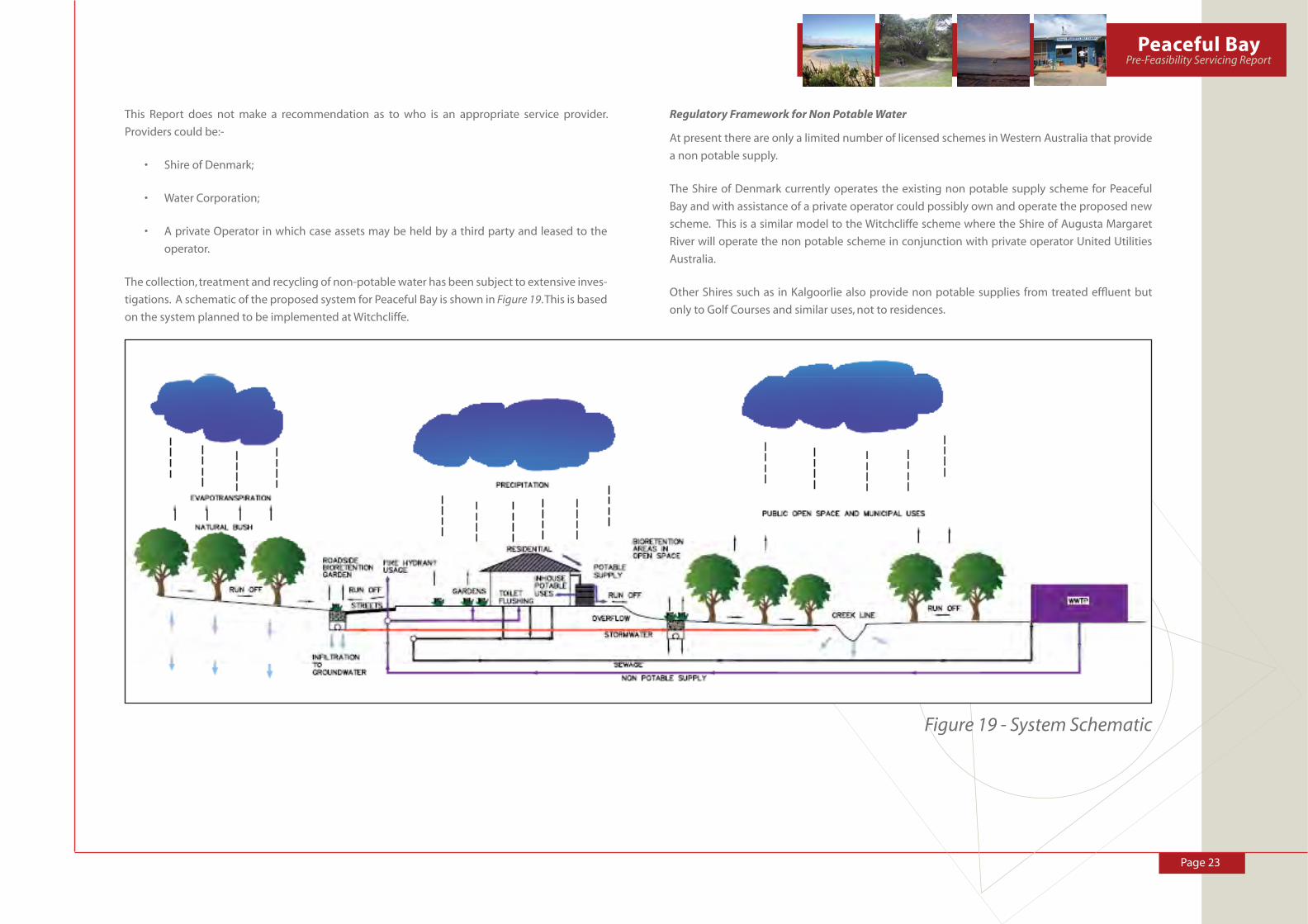
The collection, treatment and recycling of non-potable water has been subject to extensive inves-
tigations. A schematic of the proposed system for Peaceful Bay is shown in Figure 19. This is based
on the system planned to be implemented at Witchcliffe.
Regulatory Framework for Non Potable Water
At present there are only a limited number of licensed schemes in Western Australia that provide
a non potable supply.
The Shire of Denmark currently operates the existing non potable supply scheme for Peaceful
Bay and with assistance of a private operator could possibly own and operate the proposed new
scheme. This is a similar model to the Witchcliffe scheme where the Shire of Augusta Margaret
River will operate the non potable scheme in conjunction with private operator United Utilities
Australia.
Other Shires such as in Kalgoorlie also provide non potable supplies from treated effl uent but
only to Golf Courses and similar uses, not to residences.
Figure 19 - System Schematic

Page 24
The proposed non potable scheme at Peaceful Bay will be similar to that proposed at Witchcliffe
and Gracetown and would be one of the fi rst schemes constructed in Western Australia that
provide ‘Fit for Purpose’ (Class A+) treated effl uent as a non potable supply.
Because of this it is considered that the main challenge for this project will be the gaining of the
required institutional approvals for the scheme rather than the technical issues of the scheme.
The Water Services Act requires that a licensed service provider licensed by the Economic Regulatory
Authority (ERA) must operate the non potable water scheme.
A licensed provider is also required to run the sewer collection and treatment scheme and in this
instance it is proposed to be the same operator.
The service provider will need to meet all requirements of the ERA before a license is granted. The
ERA is also likely to seek the advice of the Department of Health as part of this process.
The construction and operation of the WWTP to deliver the ‘Fit For Purpose’ (class A+) non potable
water supply will require approval from the Department of Health (DoH) and a license from the
Department of Environment and Conservation (DEC).
A works approval will be required from the DEC and this will address all construction aspects of
the WWTP. Subsequently a Part 5 License (to operate) would be issued by the DEC.
The construction and operation of the plant may also require an approval from the Environmental
Protection Authority (EPA).
Waste Water Treatment Plant Site
The endorsed Peaceful Bay Local Structure Plan nominates a waste water treatment plant site
and buffer. The location of this site is supported although it may be necessary to reconsider the
treatment plan buffer requirements at such time as the treatment plant is designed and odour
and risk impacts can be assessed in more detail.
Recommendations
12. That Council endorse the principle of a preferred effl uent disposal/non potable water
supply system for Peaceful Bay which allows collected rainwater to be initially used for
potable purposes and all effl uent being collected from each lot, taken off site for treatment
and then returned to each lot to meet non-potable water demands. The system is to have a
single licensed operator which could be; the Shire of Denmark; Water Corporation; a private
Operator in which case assets may be held by a third party and leased to the operator.
13. That the Waste Water Treatment Plant Site nominated in the Peaceful Bay Local Structure
Plan is retained and the buffer requirements reassessed when the facility is designed to a
point where risks and odour can be assessed further.
14. That Council monitor current discussions and negotiations occurring in respect to
Gracetown and Witchcliffe, each of which is currently pursuing establishment of a sewerage
and third pipe water re-use scheme similar to that recommended for Peaceful Bay.

Page 25
Peaceful BayPre-Feasibility Servicing Report
9.0 IMPLEMENTATION STRATEGY
The proposed Servicing Strategy recommended in this report is innovative and at the cutting
edge of current technology. This implies a higher order of management as many of the opera-
tional models currently used for subdivision and development will not apply.
Greenfi eld sites suffer from the disadvantage of signifi cant upfront costs to establish and upgrade
infrastructure such as water treatment plants, roads, drainage treatment trains and major power
infrastructure. The need to fund this upfront infrastructure very often makes projects diffi cult to
fund and therefore initiate.
Peaceful Bay enjoys the position that leasehold lots already exist on the site and there is a potential
for these lots to be sold in a manner which is respectful of the existing leaseholders and generate
considerable funds to help in the establishment of the head works upgrades.
Private Developers will also need to make a proportional contribution to the establishment of
head works, although it needs to be recognised that these developers do not enjoy the captured
market of the existing leaseholders and therefore are unlikely to enjoy the same sales rates as
could be expected in the leasehold area.
The development of Peaceful Bay in accordance with the Peaceful Bay Local Structure Plan ulti-
mately consists of 689 lots plus a caravan park site. Even the developed areas of Peaceful Bay will
require considerable upgrading in terms of servicing infrastructure. This scale of development
implies a high level of management and fi scal responsibility. We believe that Council should
be engaging external management to coordinate these works in a responsible manner. This
management may be provided through a government instrumentality, such as LandCorp, or from
the private sector. Council may also seek to employ a full time Project Manager with suitable
experience.
Recommendation
15. Council should engage the services of a Project Manager to prepare a project delivery plan
and indicative project budget for the delivery of infrastructure services at Peaceful Bay. The
scope of project services should encompass but not necessarily be limited to:
• determining a fair process for privatising leasehold lots;
• entering into negotiations to deliver an integrated waste water collection, treatment
and distribution system in a manner consistent with the recommendations of this
report;
• Investigate the level of government’s assistance which may be available to assist in
the project;
• progress the necessary statutory rezoning and subdivisions needed to facilitate
implementation of the Peaceful Bay Structure Plan and the recommendations of this
Servicing Report;
• prepare a full feasibility analysis for the project and identify staging which will allow
the project to occur in a economically and environmentally responsible manner; and,
• to establish the extent of cost share items which all subdividers and developers will
need to contribute to and report on a mechanism which will allow this to occur.


Page 1
Peaceful BayPre-Feasibility Servicing Report
APPENDIX 1 –
WATER SENSITIVE DESIGN

Page 2
1.0 WSUD METHODS
The range of WSUD methods that are available for application to this site include
• Gross Pollutant Traps
• Swales and Buffer Strips
• Bioretention Swales and Basins
• Sedimentation Basins
• Constructed Wetlands
• Infi ltration Measures
• Sand Filters
• Aquifer Storage and Recovery
These methods are all effective for various fl ows and particle sizes as shown in Figure 1 and are
briefl y described in sections 1.1 to 1.9 of this report.
Only simple concepts are given to aid in understanding of the strategy presented this report.
Figure 1 - Pollutant size ranges for various stormwater treatment measures. Ecological Engineering (2003)
Figure 1 demonstrates that each method is applicable over a limited range of particle sizes and
hydraulic loadings and that a careful combination of methods is required to ensure effective
WSUD on a site.
In the preparation of a WSUD strategy for a site, a set of targets is normally set to guide pollutant
and nutrient removal effectiveness.
For this site the general targets that will be adopted include minimums of:
• 80% reduction in total suspended solids
• 60% reduction in total phosphorus load
• 45% reduction of total nitrogen load
• 70% reduction in gross pollutant load
These will be assessed against the design charts provided in DOE (2004) for various removal
effi ciencies for each type of WSUD method and are consistent with current DOW recommended
pollutant removal targets in the draft Urban Water Management Framework for the Swan Coastal
Plain, EES (2007).
1.1 GROSS POLLUTANT TRAPS
The general principles of Gross Pollutant Traps are:
• Capture large sediments and gross pollutants, removing these from stormwater at the start
of treatment trains and preventing clogging of later elements such as infi ltration systems
• Generally capture particles greater than 5mm
• Are normally located at the entry point of stormwater into the system
• Need a high maintenance as regular cleaning required to remove collected trash and
sediment
• Reduce litter, debris and coarse sediment from entering system
• Are proprietary (off the shelf ) designs with a wide choice available
Key design considerations include:
• Location - need to be accessible and not too visible
• Treatment Objectives - clearly target particle sizes to be removed
• Design Flows - generally only design for 1 in 1 year fl ows to capture 99.5% of all storms

Page 3
Peaceful BayPre-Feasibility Servicing Report
• Flood capacity - need to allow for impact of large fl ows
• Trapped Pollutant Storage will determine frequency of cleaning
• Maintenance needs to fi t with shire capacity to maintain
Examples of GPT’s are shown in Figures 2 to 4.
Figure 2 - Gross Pollutant Traps- CDS Pit
Figure 3 - Gross Pollutant Trap being cleaned
Figure 4 - Grated lid on entry to pipe system acting as partial GPT by trapping large litter and leaf material. Lynbrook, Vic.
As seen in Figure 4 some normal elements of a stormwater system can also have a dual function.
The grated lid on the entry to the subsoil pipe system here below the central swale, is also acting
as a GPT by trapping large litter and leaf matter and preventing it entering the system. Sediment
in this system is trapped by vegetation in the base of the swale system.
It is proposed to utilise a similar system of trapping sediments and litter in the system for Peaceful
Bay.
1.2 SWALES AND BUFFER STRIPS
The general principles of Swales and Buffer Strips are:
• Swales convey stormwater in overland fl ow rather than piped systems;
• Commonly combined with buffer strips to maximise removal of fi ne particle sizes;
• Slopes generally less than 4% as steeper slopes create scour and reduce pollutant removal
effi ciencies;
• Means of disconnecting impervious areas form waterways;
• Vegetation traps sediment and aids in reducing total suspended solids and attached pollut-
ants; and
• Particularly good at coarse sediment trapping as fi rst step in a treatment train.
Page 4
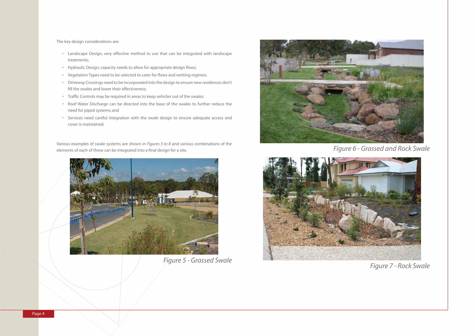
The key design considerations are:
• Landscape Design, very effective method to use that can be integrated with landscape
treatments;
• Hydraulic Design, capacity needs to allow for appropriate design fl ows;
• Vegetation Types need to be selected to cater for fl ows and wetting regimes;
• Driveway Crossings need to be incorporated into the design to ensure new residences don’t
fi ll the swales and lower their effectiveness;
• Traffi c Controls may be required in areas to keep vehicles out of the swales;
• Roof Water Discharge can be directed into the base of the swales to further reduce the
need for piped systems; and
• Services need careful integration with the swale design to ensure adequate access and
cover is maintained.
Various examples of swale systems are shown in Figures 5 to 8 and various combinations of the
elements of each of these can be integrated into a fi nal design for a site.
Figure 5 - Grassed Swale
Figure 6 - Grassed and Rock Swale
Figure 7 - Rock Swale
Page 5
Peaceful BayPre-Feasibility Servicing Report
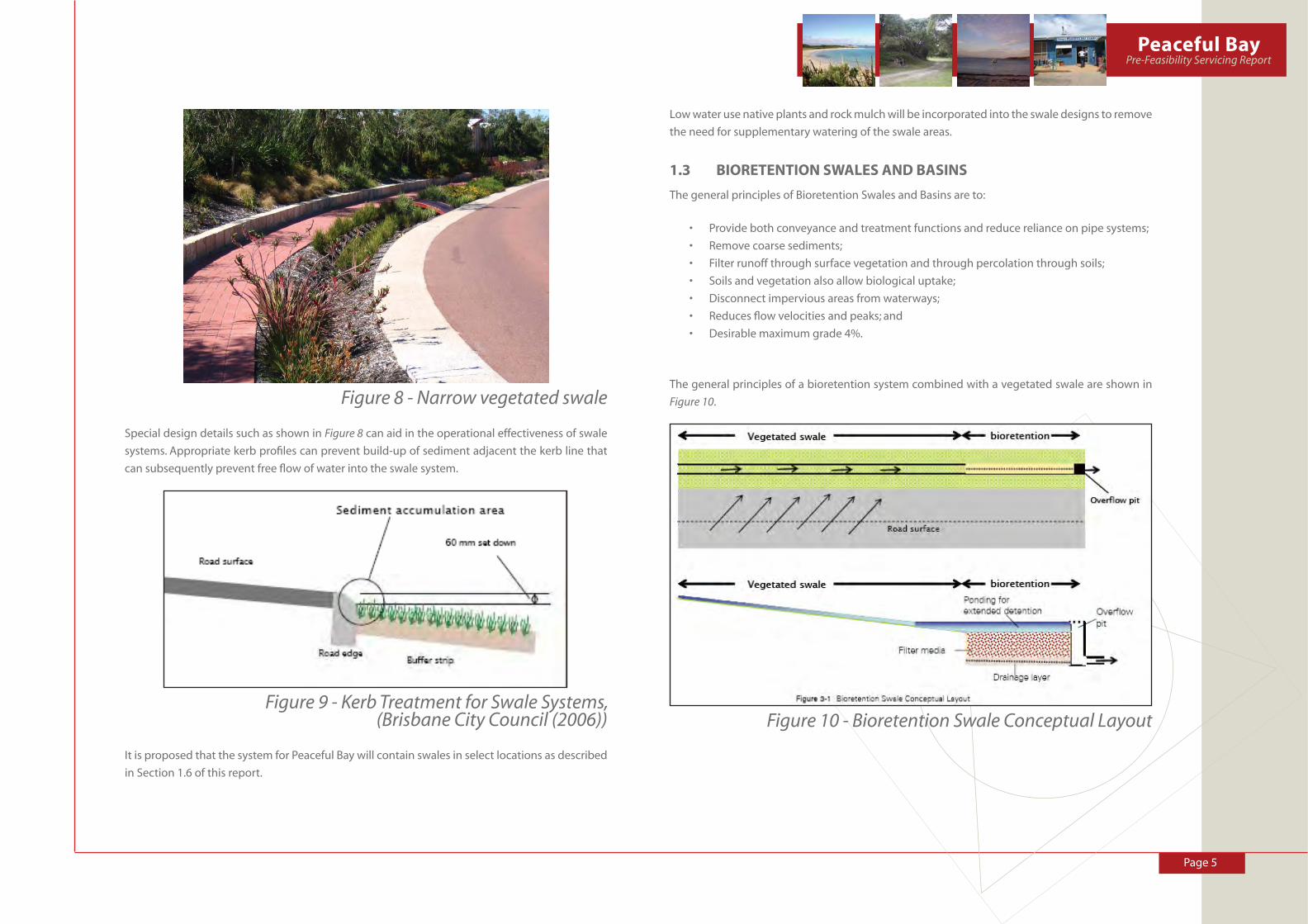
Figure 8 - Narrow vegetated swale
Special design details such as shown in Figure 8 can aid in the operational effectiveness of swale
systems. Appropriate kerb profi les can prevent build-up of sediment adjacent the kerb line that
can subsequently prevent free fl ow of water into the swale system.
Figure 9 - Kerb Treatment for Swale Systems, (Brisbane City Council (2006))
It is proposed that the system for Peaceful Bay will contain swales in select locations as described
in Section 1.6 of this report.
Low water use native plants and rock mulch will be incorporated into the swale designs to remove
the need for supplementary watering of the swale areas.
1.3 BIORETENTION SWALES AND BASINS
The general principles of Bioretention Swales and Basins are to:
• Provide both conveyance and treatment functions and reduce reliance on pipe systems;
• Remove coarse sediments;
• Filter runoff through surface vegetation and through percolation through soils;
• Soils and vegetation also allow biological uptake;
• Disconnect impervious areas from waterways;
• Reduces fl ow velocities and peaks; and
• Desirable maximum grade 4%.
The general principles of a bioretention system combined with a vegetated swale are shown in
Figure 10.
Figure 10 - Bioretention Swale Conceptual Layout
Page 6
Key Design Considerations include:
• Landscape Design, very effective method that can be integrated with landscape
treatments
• Hydraulic Design, capacity needs to allow for appropriate design fl ows
• Vegetation Types need to be selected to cater for fl ows and wetting regimes
• Exfi ltration from Insitu Soils needs to be assessed and appropriate fi lter layers provided
• Bioretention Filter Media needs to be carefully selected to enhance performance of the
system
• Driveway Crossings need to be incorporated into the design to ensure new residences don’t
fi ll the bioretention areas and lower their effectiveness
• Traffi c Controls may be required in areas to keep vehicles out of the swales.
• Roof Water Discharge can be directed into the base of the swales to further reduce the
need for piped systems
• Services need careful integration with the swale design to ensure adequate access and
cover is maintained.
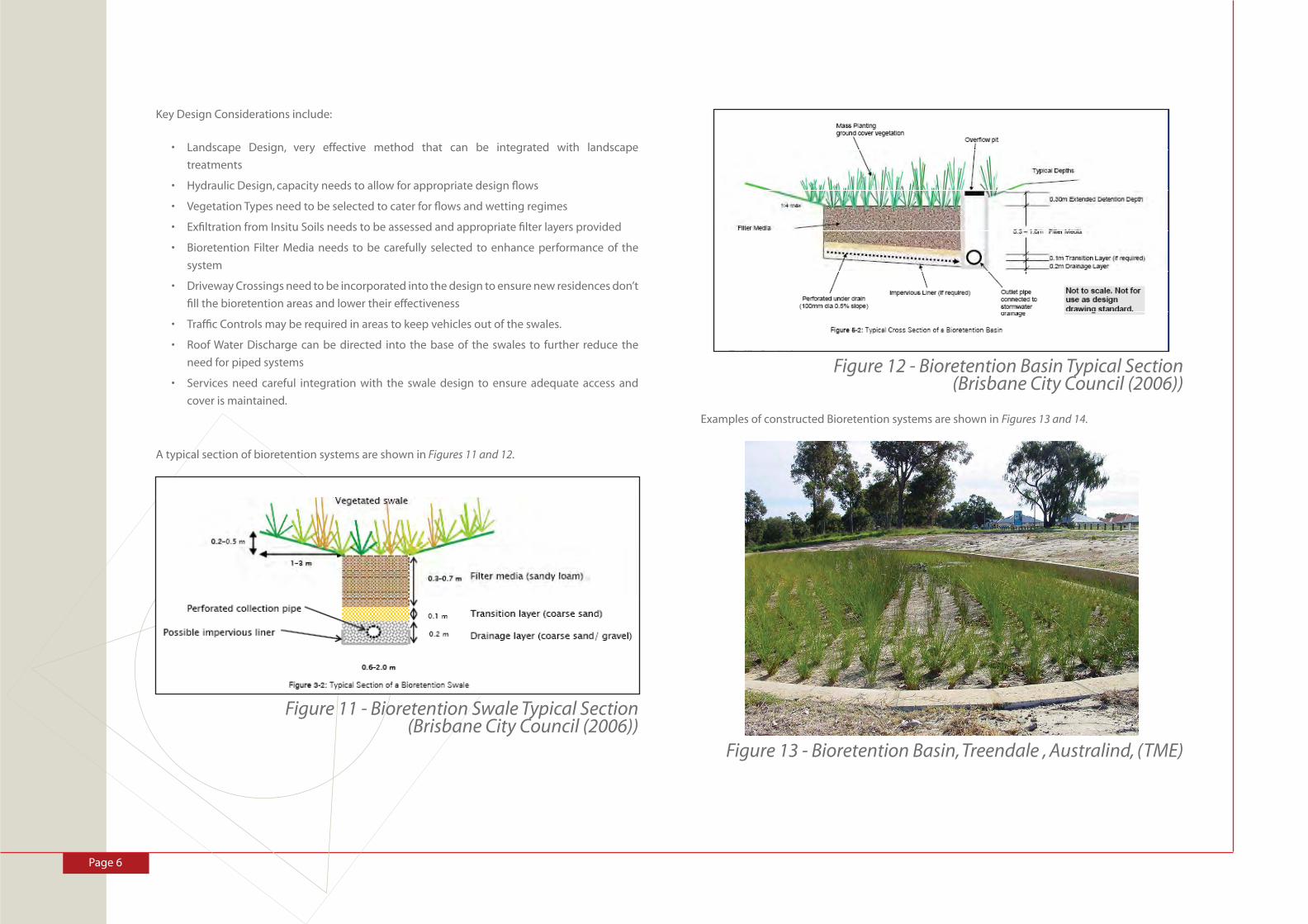
A typical section of bioretention systems are shown in Figures 11 and 12.
Figure 11 - Bioretention Swale Typical Section(Brisbane City Council (2006))
Figure 12 - Bioretention Basin Typical Section (Brisbane City Council (2006))
Examples of constructed Bioretention systems are shown in Figures 13 and 14.
Figure 13 - Bioretention Basin, Treendale , Australind, (TME)

Page 7
Peaceful BayPre-Feasibility Servicing Report
Figure 14 - Bioretention Swale at Lynbrook, Victoria.
Bioretention systems feature extensively in the WSUD system proposed for Peaceful Bay. The main
form of the bioretention systems to be used includes road side Bioretention gardens or Biopods
as shown in Figure 15.
These are planned to be constructed at the end of each residential cell and enable ready capture
and treatment of stormwater in discrete and easily maintainable locations.
Low water use native plants and rock mulch will be incorporated into the bioretention swale and
basin designs to remove the need for supplementary watering of the bioretention areas.
Figure 15 - Roadside Bioretention Garden, Wells Road, Chelsea Heights, Melbourne, (Kingston City Council (2007))
1.4 SEDIMENTATION BASINS
The general principles of Bioretention Swales and Basins are:
• They remove coarse and medium sized sediments by settling them from the water
column
• Can be permanent or temporary systems used in early construction phases
• Reduce fl ow peaks and volumes by their detention properties
• Form part of an integrated WSUD treatment train
Key Design Considerations include:
• Role in Treatment Train and appropriate siting
• Sizing of Sedimentation Basin to ensure adequate storage volume for particles collected
• Sediment Storage needs to be adequate size and accessibility
• Outlet Design must match required outfl ow rates
• Must be integrated into the Landscape Design
• Vegetation needs to be carefully specifi ed
• Maintenance aspects need to be incorporated into the design.

Page 8
A schematic of a permanent sedimentation basin is shown in Figure 16 and key design features in
Figure 17.
Figure 16 - Sedimentation Basin Conceptual Layout (Brisbane City Council (2006))
Figure 17 - Sedimentation Basin Key Elements (Brisbane City Council (2006))
Sedimentation basins are planned to be integrated into early phases of development while
sediment loads are high but would be removed once the land form stabilises and the sediment
load reduces.
An example of a temporary sediment basin is shown in Figure 38 from a development in Edenbrook
Estate, Queensland.
Figure 18 - Temporary Sedimentation Basin, Edenbrook Estate, Queensland
In this example the temporary basin is constructed adjacent the main creek line through the
centre of the site and captures all sediment from the stormwater system. Once the site is estab-
lished this system will be backfi lled and landscaped.
The same concept will be used at Peaceful Bay after initial clearing of the site and also in the early
development phases.

Page 9
Peaceful BayPre-Feasibility Servicing Report
1.5 CONSTRUCTED WETLANDS
The general principles of Constructed Wetlands are:
• Shallow extensively vegetated water bodies
• Use enhanced sedimentation, fi ne fi ltration and biological uptake to remove pollutants
from stormwater
• Reduce fl ow peaks by detention storage in the wetland
• Provide habitat for local fauna
• Can be designed as a landscape feature
• Provide opportunities for passive recreation
• Use large land areas compared to other methods
Key Design Considerations include:
• Integration into overall landscape design is essential
• Detention Time and Hydrologic Effectiveness need to be set to suit pollutant levels and
fl ow regimes
• Hydrodynamic Design needs to match fl ow regimes
• Inlet Zone needs careful design to allow for sedimentation and fl ow attenuation
• Macrophyte Zone needs to be designed to ensure it will function adequately and will be
sustainable
• Vegetation Types need careful selection
• Design features need to be incorporated to avoid mosquitoes
• Design required for maintenance access
Diagrammatic representations of the various zones within a wetland and their interrelationship
are shown in Figures 19 and 20.
These show the various zones that make up a wetland including:
• Inlet zone
• High fl ow bypass
• Shallow marsh
• Marsh
• Deep marsh
• Ephemeral zone
• Pool
• Outlet zone
Figure 19 - Wetland Design Features, (Brisbane City Council (2006))
Figure 20 - Example Bathymetry of a Wetland System,(Brisbane City Council (2006))
It is not intended to include any constructed wetlands within the Peaceful Bay WSUD strategy
although adjacent land owners may elect to incorporate these features on their land if conditions
permit.
Page 10
1.6 INFILTRATION MEASURES
The general principles of Infi ltration measures are:
• Capture stormwater and encourage infi ltration near to source
• Reduce runoff peak fl ows and volumes in small rainfall events
• Reduce downstream fl ooding
• Improve groundwater discharge
• Reduce pipe system sizes for smaller events
• Not a treatment system other than trapping coarse sediments and associated insoluble
pollutants
Key Design Considerations include:
• Design Objectives of infi ltration of 1 in 1 year near source
• Selecting Type of Infi ltration System to match particle sizes of materials in the
development
• Design (Sizing) Methods to match storage size with infi ltration capacities
• Pre-treatment of Stormwater may be required to ensure no clogging of the system
• Site Terrain may restrict applicability of these methods
• In-Situ Soils need to be of suffi cient infi ltration capacity
• Groundwater levels must be low enough not to infl uence infi ltration capacity
• Building Setbacks (clearances) may be required from infi ltration devices
• Flow Management of larger events required ( > 1 in 1 year ARI)
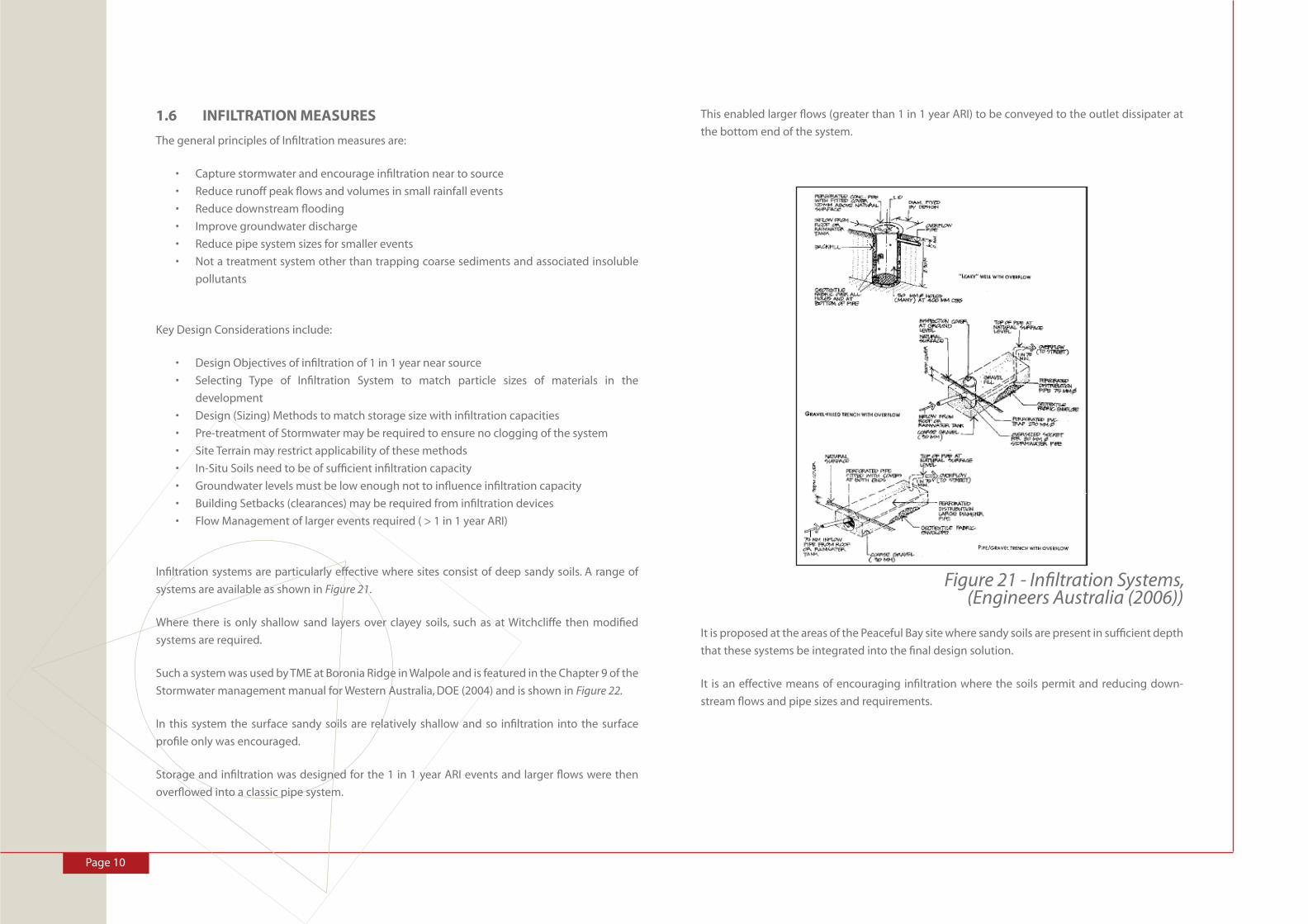
Infi ltration systems are particularly effective where sites consist of deep sandy soils. A range of
systems are available as shown in Figure 21.
Where there is only shallow sand layers over clayey soils, such as at Witchcliffe then modifi ed
systems are required.
Such a system was used by TME at Boronia Ridge in Walpole and is featured in the Chapter 9 of the
Stormwater management manual for Western Australia, DOE (2004) and is shown in Figure 22.
In this system the surface sandy soils are relatively shallow and so infi ltration into the surface
profi le only was encouraged.
Storage and infi ltration was designed for the 1 in 1 year ARI events and larger fl ows were then
overfl owed into a classic pipe system.
This enabled larger fl ows (greater than 1 in 1 year ARI) to be conveyed to the outlet dissipater at
the bottom end of the system.
Figure 21 - Infi ltration Systems, (Engineers Australia (2006))
It is proposed at the areas of the Peaceful Bay site where sandy soils are present in suffi cient depth
that these systems be integrated into the fi nal design solution.
It is an effective means of encouraging infi ltration where the soils permit and reducing down-
stream fl ows and pipe sizes and requirements.

Page 11
Peaceful BayPre-Feasibility Servicing Report
Figure 22 - Boronia Ridge Stormwater Infi ltration System, DOE (2004) Chapter 9 released in 2007.
1.7 SAND FILTERS
The general principles of Sand Filters are:
• Similar to Bioretention systems
• Passes through media that has no vegetation on surface
• Reduced performance compared to Bioretention systems
• More maintenance and can clog easier
• Not used much in WA
An indicative layout is shown in Figure 23. These systems are not planned to be used at Peaceful
Bay.
Figure 23 - Sand Filter Schematic, (Brisbane City Council (2006))

Page 12
1.8 AQUIFER STORAGE AND RECOVERY (ASR)
The general principles of Aquifer Storage and Recovery are:
• Introducing recycled water into underground aquifers
• Via direct injection or gravity fl ow
• Can be low cost water storage compared to surface storage
• Can reduce losses
• Need to ensure don’t reduce quality of the aquifer
• Store excess fl ows in wet period for reuse in dry periods
• Used extensively in South Australia
These systems are used extensively in South Australia and require suitable aquifer properties to
allow ready injection and recovery of the treated stormwater.
The aquifer at Peaceful Bay is not considered suitable for this method and also it is anticipated the
groundwater rise on the site would prevent such methods being used effectively. A schematic of
an ASR scheme is shown ion Figure 24.
Figure 24 - Components of a Well Confi gured ASR System(Brisbane City Council (2006))

Page 13
Peaceful BayPre-Feasibility Servicing Report
1.9 COMPARISON OF METHODS
In selection of the appropriate methods for use at the Peaceful Bay site a balance between a
number criteria needs to be considered including:
• Soil conditions
• Climate
• Hydrology
• Integration with landscaping
• Capital cost
• Maintenance cost
• Public acceptability
• Environmental benefi ts
Each of the various methods also has varying land requirements as shown in Figure 25 with gener-
ally the infi ltration and bioretention systems having the smallest required footprints.
Figure 25 - Comparison of surface areas required for each type of WSUD method. (Wong)

Page 1
Peaceful BayPre-Feasibility Servicing Report
APPENDIX 2 -
RAINWATER SYSTEMS

Page 2
1.0 RAINWATER SYSTEMS
Rainwater tanks are currently installed in around 17% of Australian households but still only
provide a small portion of potable supplies.
In some states such as South Australia the proportion of rainwater tanks is very high at 48% but it
is thought this is largely due to the historically poor taste of the tap water. More recently this has
improved and the take up rate of rain tanks has declined. Marsden Jacob Assoc (2007)
This high proportion of tanks in South Australia is shown in Figure 1.
Figure 1 - Proportions of Households with a Rainwater Tank, Marsden Jacob Assoc (2007)
“Roof run-off or rainwater generally provides a supply of clear, very soft and low salinity water”
Department of Agriculture, 2004.
Providing systems are installed correctly with all recommended practices adopted then rain water
systems present very safe means of supply.
Rain tank systems should be installed in accordance with established guides such as produced by
the Department of Health.
Rain tank systems can be either above ground or below ground systems as shown in Figures 2
and 3. Above ground systems are much cheaper however and are favoured where land is readily
available for the required footprint of the tank.
Figure 2 -Confi guration of Above Ground System, LHCCREMS, 2002

Page 3
Peaceful BayPre-Feasibility Servicing Report
Figure 3 - Confi guration of Pressure System on Below Ground System, LHCCREMS, 2002
Various types and sizes of tanks available on the market and their size will depend on roof area
and reliability required. Each tank is proposed to be owned and maintained by the individual lot
owners.
Examples of various tanks are shown in Figures 4 and 5.
Figure 4 - Above Ground Rain Tanks
Figure 5 - Below Ground Rain Tank
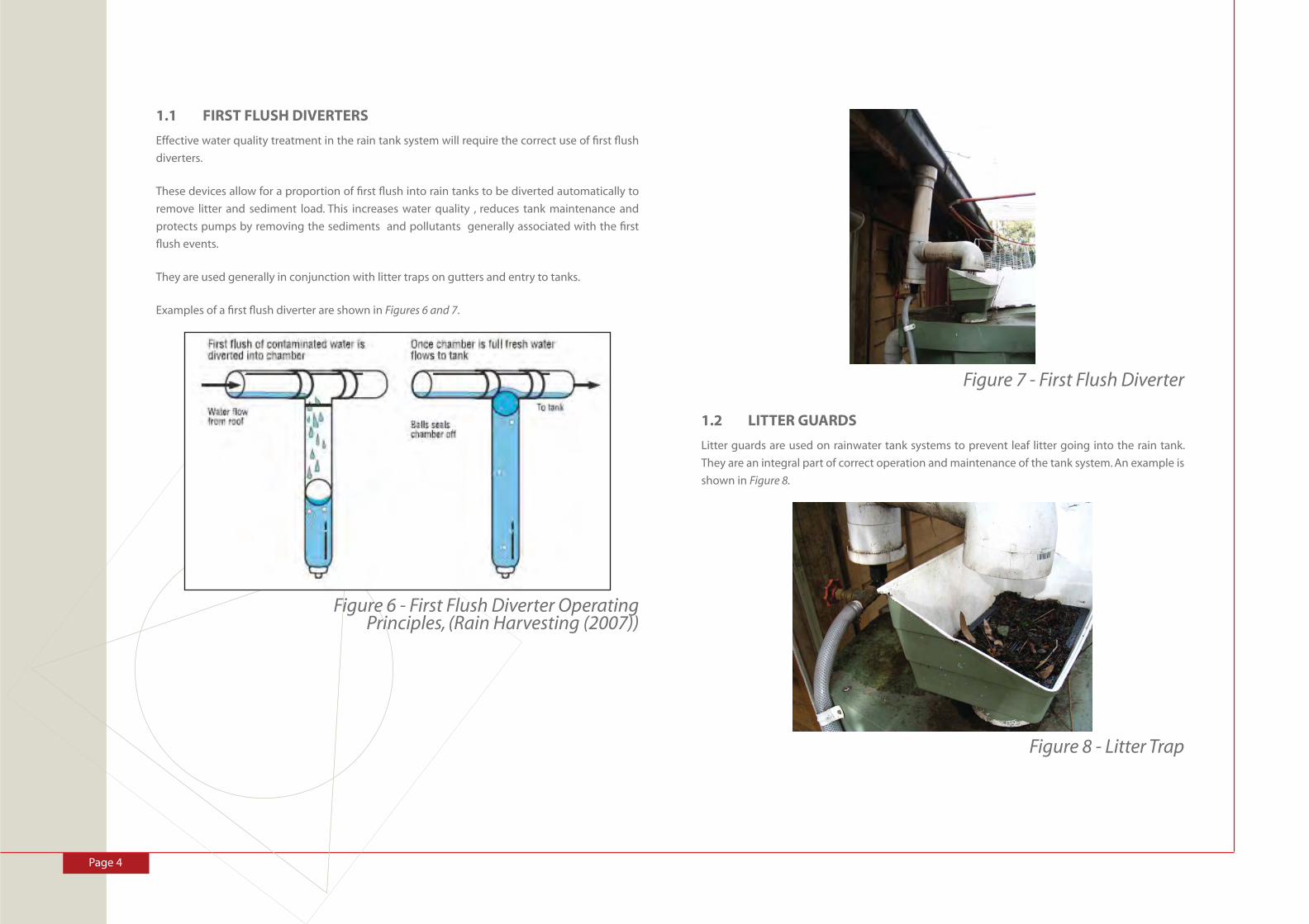
Page 4
1.1 FIRST FLUSH DIVERTERS
Effective water quality treatment in the rain tank system will require the correct use of fi rst fl ush
diverters.
These devices allow for a proportion of fi rst fl ush into rain tanks to be diverted automatically to
remove litter and sediment load. This increases water quality , reduces tank maintenance and
protects pumps by removing the sediments and pollutants generally associated with the fi rst
fl ush events.
They are used generally in conjunction with litter traps on gutters and entry to tanks.
Examples of a fi rst fl ush diverter are shown in Figures 6 and 7.
Figure 6 - First Flush Diverter Operating Principles, (Rain Harvesting (2007))
Figure 7 - First Flush Diverter
1.2 LITTER GUARDS
Litter guards are used on rainwater tank systems to prevent leaf litter going into the rain tank.
They are an integral part of correct operation and maintenance of the tank system. An example is
shown in Figure 8.
Figure 8 - Litter Trap

Page 5
Peaceful BayPre-Feasibility Servicing Report
1.3 UV DISINFECTION
To provide a secure and safe water supply free of bacteria and other pathogens it is also recom-
mended that a UV lamp be used to disinfect water prior to fl ow inside the house for potable use.
UV light systems require relatively low maintenance and have the advantage of not requiring
chemicals. These systems should also include a sensor that clearly indicates when the lamp is not
operational. enHealth, 2004.
An example of a system is shown in Figure 9.
Figure 9 - UV Disinfection System
1.4 RAINWATER TANK MAINTENANCE
Correct and safe operation of rain tank systems requires a simple and effective maintenance
protocol. Numerous guides are available for maintenance of rain tank systems in including
Department of Health, 2005
General principles of tank maintenance and operation include:
• Keep gutters and roofs clean and in good repair
• Use fi rst fl ush diverters
• Use a litter trap on the inlet to the system
• Screen the inlet and overfl ow for insects/ animals
• Cover and seal the tank to prevent the entry of sunlight, dust, animals, mosquitoes and
other insects
• Install a properly fi tting manhole cover for access and cleaning
• Use materials compliant with Australian Standards for drinking water purposes
• Only clean tank when sediment levels become unacceptably deep
• Draw water from the tank from above the anaerobic/ sediment layer
1.5 WATER USE REDUCTION
To aid in minimising the amount of rainwater required to service each house it is also recom-
mended that water use reduction methods be undertaken or encouraged for each householder.
This includes promoting:
• Use water effi cient devices
• Reduce garden usage
• Water conservation within household
• Ongoing education
The largest incentive for households will be the awareness of their own supplies and the capacity
of these supplies to serve throughout a summer period. This is unlike houses that have a piped
supply where no limitations on supply are even considered by the householder except possibly
for garden watering in times of restrictions.
Figure 10 - Water Saving Appliances