Embed Size (px)
Citation preview
Structural Analysis of Historical Constructions, New Delhi 2006P.B. Lourenço, P. Roca, C. Modena, S. Agrawal (Eds.)
1 INTRODUCTION
Grouting constitutes one of the most common techniques applied to historic masonries. Al-though grouting is a non-reversible technique, it is well accepted even for monuments of high historical and architectural value, since the materials added to masonry may be of the same na-ture as the in situ ones and because of the positive effect of grouting on the mechanical proper-ties of masonry. In fact, grouting can be a durable and mechanically efficient intervention tech-nique.
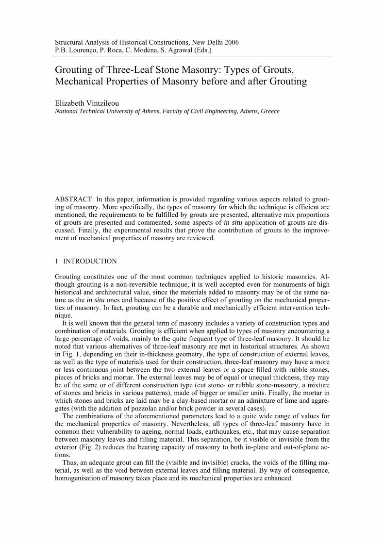
It is well known that the general term of masonry includes a variety of construction types and combination of materials. Grouting is efficient when applied to types of masonry encountering a large percentage of voids, mainly to the quite frequent type of three-leaf masonry. It should be noted that various alternatives of three-leaf masonry are met in historical structures. As shown in Fig. 1, depending on their in-thickness geometry, the type of construction of external leaves, as well as the type of materials used for their construction, three-leaf masonry may have a more or less continuous joint between the two external leaves or a space filled with rubble stones, pieces of bricks and mortar. The external leaves may be of equal or unequal thickness, they may be of the same or of different construction type (cut stone- or rubble stone-masonry, a mixture of stones and bricks in various patterns), made of bigger or smaller units. Finally, the mortar in which stones and bricks are laid may be a clay-based mortar or an admixture of lime and aggre-gates (with the addition of pozzolan and/or brick powder in several cases).
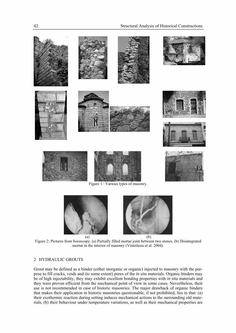
The combinations of the aforementioned parameters lead to a quite wide range of values for the mechanical properties of masonry. Nevertheless, all types of three-leaf masonry have in common their vulnerability to ageing, normal loads, earthquakes, etc., that may cause separation between masonry leaves and filling material. This separation, be it visible or invisible from the exterior (Fig. 2) reduces the bearing capacity of masonry to both in-plane and out-of-plane ac-tions.
Thus, an adequate grout can fill the (visible and invisible) cracks, the voids of the filling ma-terial, as well as the void between external leaves and filling material. By way of consequence, homogenisation of masonry takes place and its mechanical properties are enhanced.
Grouting of Three-Leaf Stone Masonry: Types of Grouts, Mechanical Properties of Masonry before and after Grouting
Elizabeth Vintzileou National Technical University of Athens, Faculty of Civil Engineering, Athens, Greece
ABSTRACT: In this paper, information is provided regarding various aspects related to grout-ing of masonry. More specifically, the types of masonry for which the technique is efficient are mentioned, the requirements to be fulfilled by grouts are presented, alternative mix proportions of grouts are presented and commented, some aspects of in situ application of grouts are dis-cussed. Finally, the experimental results that prove the contribution of grouts to the improve-ment of mechanical properties of masonry are reviewed.
42 Structural Analysis of Historical Constructions
Figure 1 : Various types of masonry.
(a) (b)
Figure 2: Pictures from boroscopy: (a) Partially filled mortar joint between two stones, (b) Disintegrated mortar in the interior of masonry (Vintzileou et al. 2004).
2 HYDRAULIC GROUTS
Grout may be defined as a binder (either inorganic or organic) injected to masonry with the pur-pose to fill cracks, voids and (to some extent) pores of the in situ materials. Organic binders may be of high injectability, they may exhibit excellent bonding properties with in situ materials and they were proven efficient from the mechanical point of view in some cases. Nevertheless, their use is not recommended in case of historic masonries. The major drawback of organic binders that makes their application in historic masonries questionable, if not prohibited, lies in that: (a) their exothermic reaction during setting induces mechanical actions to the surrounding old mate-rials, (b) their behaviour under temperature variations, as well as their mechanical properties are
Elizabeth Vintzileou 43
substantially different than those of masonry and (c) pronounced deterioration of their bonding properties occurs when they are applied to a wet medium. Thus, in what follows, only hydraulic binders are dealt with, since they are both from the chemical-physical and mechanical view-points more adequate for use in historic masonries, provided that they are adequately designed.
Hydraulic binders may be subdivided into two main categories, namely cement based grouts and hydraulic lime based grouts.
Cement based grouts constitute the first application of grouts to masonry structures. They were initially pure cement grouts. However, it was proven that their injectability properties were inadequate for filling the small size voids and cracks of historic masonries (because of clog-ging). This drawback of pure cement grouts led Miltiadou (1990) to the addition of ultra fine materials (on the basis of specific granularity criteria). In this way she reached grouts of high in-jectability and adequate mechanical properties at the same time. On the other hand, the need for a wide range of mechanical properties of grouts to be available (in order to serve the specific needs of each historic structure) was recognized. Thus, binary grouts (mixes of cement and hy-drated lime, natural or artificial pozzolans, silica fume, etc.) and ternary grouts (cement, hy-drated lime and natural or artificial pozzolans) were developed. The cement percentage was varying mainly between 50% and 75%. Grouts of this type reach compressive strengths varying between 10 to 30.0 MPa with tensile strength range of 1.2 to 3.0 MPa (Miltiadou 1990) and they were proven to be efficient in enhancing the mechanical properties of masonry to which they are injected (Vintzileou et al. 1995). Nevertheless, mechanical tests (see Section 4) did not confirm the need for grouts with high cement content. Furthermore, the use of grouts with reduced ce-ment content would be beneficial for the protection of mosaics, frescoes and decorative ele-ments on masonry surfaces, as physico-chemical incompatibility with the in situ materials is prevented. Thus, enhanced durability of the intervention is expected. All this led to the devel-opment and investigation of alternative mixes, namely ternary grouts with reduced cement con-tent.
Ternary grouts composed of more than two constituents, such as: cement (in a reduced per-centage, say 30% to 50%), lime, pozzolans (natural or artificial), ultra fine materials (such as fly ash or silica fume), were developed. Their performance is discussed in this paper, as well. As for the obtained mechanical properties, for a cement content of 30%wt, compressive strengths as high as 10.0 MPa and tensile strengths of the order of 3.0 MPa can be reached (Toumbakari 2002, Miltiadou et al. 2006a).
It is only recently that the use of hydraulic lime based grouts (pure hydraulic lime or in com-bination with a pozzolanic material) was investigated, although their similarity with the in situ materials may offer a promising solution, provided that they prove to be mechanically efficient as well (see Section 4). It should be noted that Valluzzi (2004) developed grouts with a com-pressive strength between 3.0 and 5.0 MPa (at the age of 2 months). In a recent work (Miltiadou et al. 2006a), hydraulic lime grouts were developed for application to a byzantine monument. At the age of six months, a compressive strength of 6.4 MPa was reached, whereas the flexural strength of this grout was equal to 3.9 MPa.
2.1 Properties of hydraulic grouts A grout to be injected to masonry should comply with a set of requirements, namely rheologi-cal, physical, chemical and mechanical.
Rheological requirements include (a) injectability (penetrability into fine cracks and voids, according to the design and sufficient fluidity for the grout to be diffused into masonry), and (c) stability (excessive bleeding and segregation of the grout should be avoided).
Physical requirements comprise (a) low hydration heat (as high temperatures may adversely affect the bond with the substrate), (b) limited shrinkage (that may cause microcracking along the grout/in situ materials interfaces, before the application of any load) (c) adequate hardening time (not to hinder the evolution of intervention works and to allow for development of me-chanical properties within adequate time period), (d) hygroscopic properties (such as, limited volume changes due to humidity variations, water insoluble grout, etc.).
Chemical requirements (related to both durability and mechanical properties of the grouted masonry) refer, for example, to (a) resistance to expansion: some hydration products (e.g. et-tringite and portlandite) being of larger volume than the reacting materials exert a crystalline
44 Structural Analysis of Historical Constructions
pressure during their formation. This pressure within the hardened material may lead to cracking (as in the case of alkali-silica reaction), (b) to the chemical stability of the products of chemical reactions, taking place between the grout and the in situ materials.
Mechanical requirements are related to the desirable mechanical properties of the grouted masonry (i.e. strength and deformability characteristics), depending on the actual state of ma-sonry, the actions to be imposed, the overall scheme of interventions, etc.
A detailed review of the available literature on each of the aforementioned properties and for the two categories of grouts would be beyond the field of competence of the author; it is also out of the scope of this paper. For a comprehensive literature survey on the subject, as well as for results on specific grout mixes, the reader may refer to Miltiadou (1990), Toumbakari (2002), Valluzzi (2004) and Miltiadou et al. (2006b).
Nevertheless, for the benefit of the reader and in order to contribute to a better understanding of the selection of materials used for grouts, some information is provided in the following sec-tions.
2.1.1 Penetrability For a grout to be injectable to a cracked or porous material, the maximum grain size of the mix, as well as the distribution of various grain sizes (grading curve) should be compatible with the size of the cracks and voids to be filled.
According to Miltiadou et al. (2003), the grout is able to penetrate unobstructed to the voids, when there is an adequate relation between the effective maximum grain size of the solid phase and the nominal minimum width of the voids in masonry, as well as when an adequate grading curve of the solid phase is ensured. The authors, based on the available literature, prove that the diameter of the larger solid grains of the grout should be substantially smaller than the nominal value of the width of cracks or the aperture of the orifices to be filled. This is because of (i) the friction developed due to the irregular shape of the grains, (ii) the electrostatic connection be-tween particles and (iii) the agglomeration caused by the immediate hydration of the fines.
Another parameter influencing penetrability is the grading curve (distribution of various grain sizes, the specific surface, modulus of fineness, etc.). It is obvious that the grading curve of the solid phase and the distribution of void sizes within the masonry to be grouted are interrelated. Paillère et al. (1984, 1989), Miltiadou (1989) and Miltiadou (1990) have investigated those pa-rameters, using the standard sand column test developed by LCPC, France (NF P 18-891). This standard test allows for voids and cracks of various sizes to be simulated, thanks to an adequate grading curve of the sand. It should be noted that Miltiadou (1990), who applied this standard test method, has reached binary or ternary cement-based grouts of improved fluidity, stability and penetrability by substituting part of the cement content by ultra fine materials such as hy-drated lime, natural and artificial pozzolans up to a certain percentage. This positive result was obtained thanks to the improvement of the grading curve of the cement. Furthermore, adequate mechanical properties and improved durability characteristics were also ensured. It is to be mentioned that the mixing procedure of the grout is of paramount importance for penetrability. In fact, the deflocculation of agglomerates, the dispersion and homogeneous dis-tribution of the grains of the solid phase in the water, the wetting of their entire surface is a sine qua non condition for penetrability to be ensured. High turbulence mixing may be adequate when hydrated lime or/and natural pozzolans are added to the mix; ultrasound dispersion is in any case the best method of mixing grouts and absolutely necessary when densified silica fume is used (Paillère et al. 1989, Miltiadou 1990). This result was also confirmed by Toumbakari (2002). In fact, the use of ultrasound dispersion equipment was needed to make a grout with sil-ica fume to penetrate fine cracks (0.15-0.30 mm) without changing the water or superplasticizer content of the mix.
2.1.2 Fluidity When the solid phase of the grout is adequately “designed” for penetrability, fluidity of the mix has also to be ensured. In fact, the fluid grout should be able to move easily within the voids and cracks of masonry, i.e. without excessive friction that would lead to increased pumping pres-sure. This should be avoided since the fluid, entering under high pressure into a poor quality medium, can cause cracking and further deterioration of masonry. Even if cracking is not so se-
Elizabeth Vintzileou 45
vere to deteriorate masonry, uncontrollable flow of the grout out of the cracked masonry may damage frescoes, mosaics or simply plasters that are to be preserved.
Fluidity (estimated, in practice, by measuring the time needed for a certain quantity of the grout to pass through a given outflow section) depends mainly on the grain size distribution, on the nature and shape of the grains and the specific surface of the solid phase, the water content and the mixing method. Fluidity can be enhanced by various means, such as increase of water content, use of adequate mixing method and addition of superplasticizer to the mix. It is re-minded here that water cannot be added to quantities that would increase bleeding beyond a cer-tain limit. The addition of a superplasticizer would be beneficial in this respect, as it may reduce the water demand, provided that its properties are checked and proven to be adequate for the specific mix.
2.1.3 Stability The third basic property of a grout is stability, i.e. its ability to preserve homogeneity during ap-plication and up to the hardening of the injected grout. Stability is normally expressed in terms of avoiding two undesirable phenomena, namely excessive bleeding (>5%) and segregation. These phenomena lead to incomplete filling of voids, to blocking of narrow flow channels, thus hindering the entire grout to penetrate (and, by way of consequence, to increase of the pressure), and finally to heterogeneous mechanical and durability characteristics of the masonry after in-jection. On the basis of the available literature, as well as based on theoretical considerations, Miltiadou et al. (2006b) suggest a methodology for the basic parameters that affect stability of hydraulic grouts to be determined, provided that an adequate mixing procedure is used. Those parameters are the ratio water/solids, the specific surface of the solid phase, as well as the su-perplasticizer content, if added to the mix.
2.2 Design of grouts As mentioned in section 2.1, the grout as well as the method of application thereof should be designed, so that all performance requirements are simultaneously fulfilled. However, as stated also in Miltiadou et al. (2006b), the fulfilment of requirements such as high injectability under low pressure not to harm the masonry, improvement of mechanical properties of masonry and durability of the intervention without side effects (a prerequisite for the principle of re-intervention to be respected) depends on parameters contradicting each other. It ensues, there-fore, that a methodology is needed for the design of grouts. Such a methodology (suggested in Miltiadou et al. 2006b) should be based on the data of the specific historic structure (i.e. the properties of building materials and of masonry as a whole, the geometry, the presence of deco-rative elements, the pathology, the available materials), in order to design the appropriate mix that will serve the purpose of the intervention, as defined in the architectural and structural de-sign of the preservation.
It should be noted that the selection of a mix to be applied to a given masonry is based on the results of laboratory tests. In fact, various trial mixes have to be prepared and tested, in order to determine their injectability, durability and mechanical properties. Also, the limiting values of each property of the grout (in order to judge about its suitability) depend on the testing method adopted by the testing laboratory, as harmonized standards are not yet available.
As a conclusion, one may say that the prerequisites for a rational design of a grout are (a) good knowledge of the specific properties of masonry to be grouted (geometry, constituent ma-terials, mechanical properties, actual state, etc.), (b) the target of the intervention, (c) specific knowledge on material science, (d) parameter studies and laboratory testing. It is, therefore, an activity that cannot be undertaken by a non-specialized Engineer. Nevertheless, Structural Engi-neers dealing with preservation of monuments should acquire basic knowledge on the subject, in order to be able to provide information that is necessary for the design of grouts, as well as to set adequate structural requirements to be fulfilled by the grout.
46 Structural Analysis of Historical Constructions
3 APPLICATION OF GROUTS
The application of grouts consists of several steps, namely preparation of masonry to be grouted, preparation of the mix to be injected, grouting and, finally, cleaning and finishing the surface of the grouted masonry. In the following paragraphs, the guidelines developed by the Directorate for Technical Research on Restoration of the Hellenic Ministry of Culture (DTRR-HMC) are summarized.
3.1 Preparation of masonry Before the application of grouts, masonry has to be adequately prepared. In case masonry is plastered and the plaster is not to be preserved, it should be removed, to allow for better sealing of cracks and for repointing (if needed), as well as for better follow up of grouting procedure. When the plaster cannot be removed or, in the quite usual case for monuments, when there are mosaics or frescoes that should not be damaged during the whole procedure, special measures have to be taken, as described further on. In addition, if masonry is cracked, loose material should be removed and the region of cracks should be cleaned to allow for their opening to be visible.
3.1.1 Drilling of injection holes and installation of plastic tubes Holes are drilled to allow both for injecting the grout and for controlling the overflow thereof.
Holes should be drilled deep enough for the grout to reach the zone of masonry that should be filled. They are drilled at adequate distances, on both faces of masonry if possible, to form a grid. The distance of consecutive holes depends on the type and the thickness of masonry, as well as on the damages it presents and it should be determined by the Designer. In any case, it should not exceed 0.50-1.00 m or the thickness of masonry. The locations of holes on one face should not coincide with their locations on the other face. Holes are normally drilled in mortar joints and inclined downwards.
When masonry is cracked, holes should also be drilled at distances along the cracks, in order to ensure filling of them with grout.
When masonry is plastered or covered with frescoes and mosaics to be protected, additional (smaller in diameter) holes should be drilled to reduce as much as possible the grout quantity to overflow in the region to be protected.
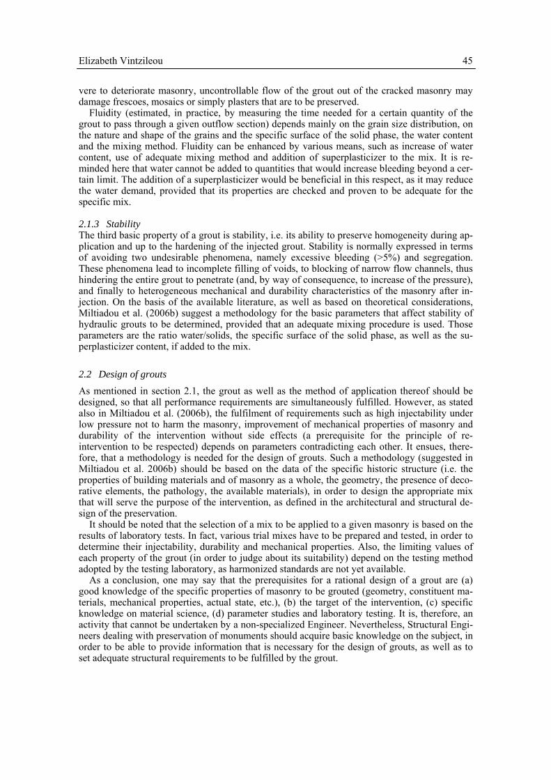
Transparent plastic tubes (of a diameter equal to 10.0 mm) are installed in all drilled holes. When old mortars or decorative elements like frescoes or mosaics are present or in case of fine cracks of architectural members, the diameter of the plastic tubes can range between 1.0 and 10.0 mm. In Fig. 3, some examples of preparation of masonry for grouting are shown. In the case of the laboratory specimen (shown in Fig. 3), plastic tubes of various diameters (from 2.7 mm to 10 mm) were installed. The smaller diameter tubes were placed in the region of the mosaics.
Plastic tubes reaching different depths in masonry should be adequately marked and reported to adequate drawings or sketches. They should also be numbered (from bottom to top of ma-sonry). Entrances and corresponding exits of the grout are recorded, together with the volume of the consumed grout, as well as with any change of injection pressure at the entrance to the wall. In this way, the injection process is better controlled and the quality of the intervention can be ensured.
3.1.2 Re-pointing, sealing of cracks and surface voids Re-pointing is necessary, when the in situ mortar at the surface of masonry is in poor condition and, therefore, it has to be replaced, to allow for efficient injection. Lime/pozzolan mortars or hydraulic lime mortars are normally used for re-pointing. Along with re-pointing, sealing of cracks and other surface voids is necessary to avoid uncontrollable leaking of the grout during its application.
It should be noted that, since the overflow of grout at places that were not detected during re-pointing and sealing cannot be excluded, the necessary materials for the immediate control of overflow and the preparation of an adequate paste (pozzolan paste, clay paste or paper pulpe,
Elizabeth Vintzileou 47
etc.) to stop the leakage should be readily available. If necessary, masonry should be cleaned immediately after the undesirable overflow.
3.1.3 Mixing of grout and injection As mentioned in the previous sections, depending on the composition of the grout to be applied, a high turbulence mixer or ultrasound dispersion equipment must be used. In any case, the use of ultrasound dispersion mixer is advisable, when available. Once the mix is prepared (after an adequate time of mixing-approx. 2 min/solid constituent), it is drained to a vessel used as a buffer to the pumping equipment. This vessel is equipped with a mechanical device of low tur-bulence to gently stir the grout during injection. Thus a continuous process of injection is en-sured.
The grout is pumped into masonry using a flexible pipe with a nozzle of adequate diameter at its end equipped with a manometer (to control the pressure). Before the initiation of injection process, the adequate functioning of the whole system has to be checked. Note that the stability, the density and the apparent viscosity of the grout should be tested in situ, on a regular basis.
The grout has to be injected at low pressure (0.5 to 1 bar). This is of major importance for the pro-tection of masonry, as well as to avoid uncontrollable exit of the grout. Grouting starts from the bottom (proceeding along the length of the element to be grouted) to the top, in order to ensure that the grout fills all internal voids. At the same time, a record is kept of tubes from which grout is introduced to or comes out from masonry; the consumed grout quantity is also recorded. In case of vulnerable structures, grouting should not be performed to a height of masonry ex-ceeding approximately 1m per day, in order to avoid excessive internal (hydrostatic) pressure of the grout that could damage the masonry.
Once grouting is completed, masonry is adequately cured. The protruding length of plastic tubes is cut and masonry is repointed or plastered if provided so.
(a) (b) (c)
(d)
(e) (f) (g)
Figure 3 : (a) Sealing of cracks, (b) Drilling of holes, (c) and (d) plastic tubes are installed and numbered, (e) and (f) masonry ready to be grouted: Agia Eirini church (Miltiadou-Fezans 2004), BA Range of Cells of Osios Loucas Monastery (Boetia) [courtesy Dr Miltiadou, Hellenic Ministry of Culture], (g) a marble
column in Parthenon (Athens Acropolis) after grouting (Miltiadou et al. 2005).
4 MECHANICAL PROPERTIES OF MASONRY BEFORE AND AFTER GROUTING
The mechanical properties of three leaf masonry (either ungrouted or grouted) were investigated within several research programs. Almost full scale specimens were tested to their maximum re-
48 Structural Analysis of Historical Constructions
sistance, they were unloaded, grouted and then reloaded to failure. In what follows, the main findings of the available experimental results are summarized and commented.
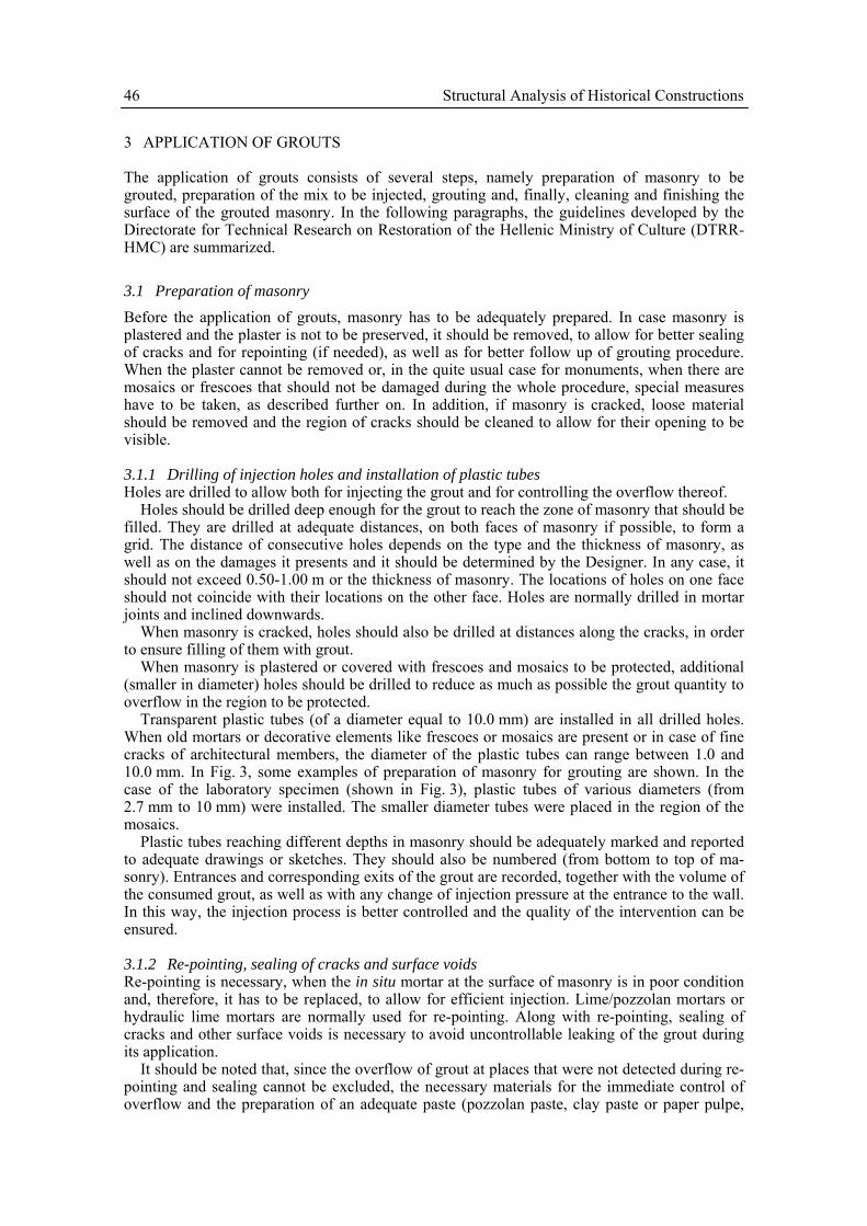
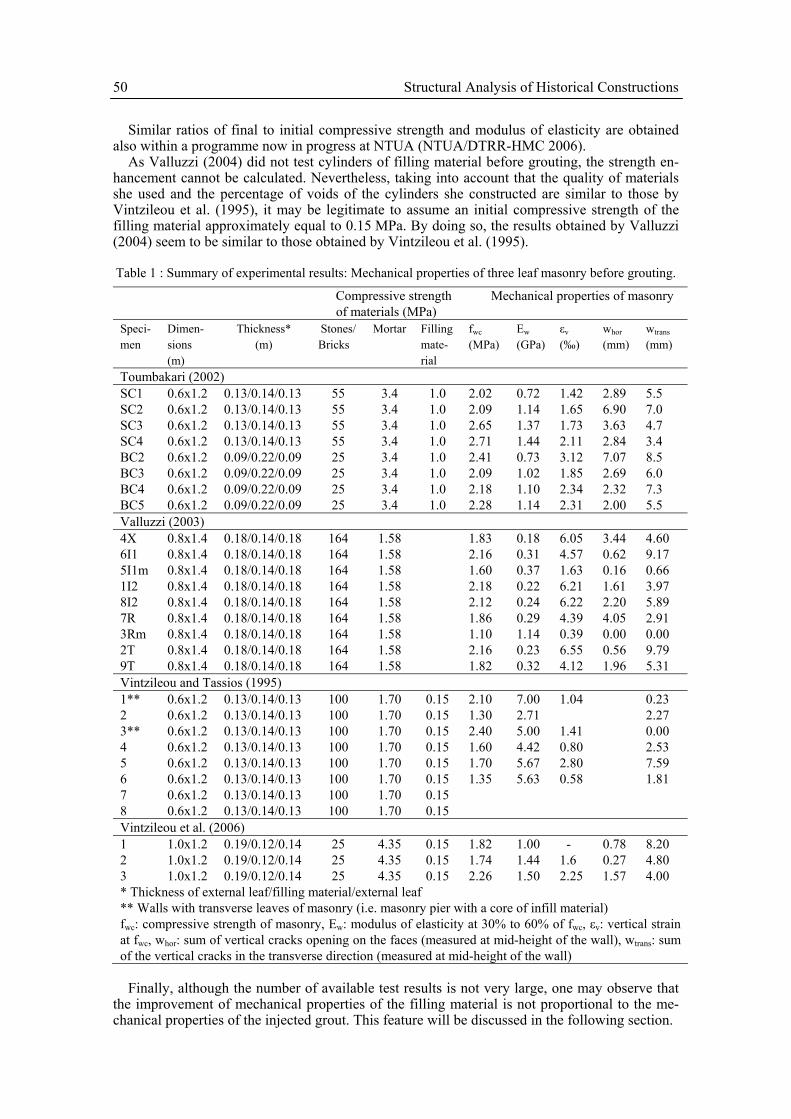
4.1 Properties of ungrouted three leaf masonry Table 1 summarizes the experimental results regarding the properties of three leaf masonry wal-lettes tested to compression. One may observe that the compressive strength of stones (or, in one case, of bricks) used for the construction of specimens was varying between 25 MPa and 164 MPa. The range of compressive strength of the mortar was less wide (1.60 to 4.40 MPa). In all cases, the filling material was constructed in a similar way (a mix of coarse aggregates and mortar was placed between the two external leaves without any compaction) to reach a rather high percentage of voids (30% to 40%), as encountered in historic masonries. The compressive strength of the filling material was determined by testing cylinders (Fig. 4) and it was either equal to 1.0 MPa (Toumbakari 2002) or equal to 0.15 MPa (Miltiadou 1990, Vintzileou et al. 1995, 2006).
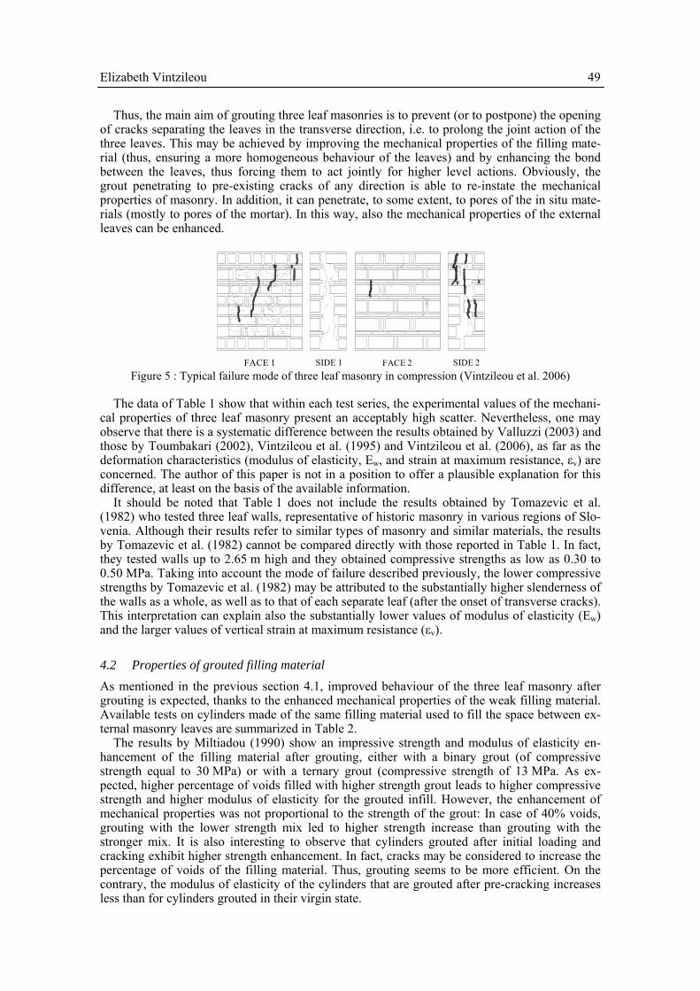
Despite the differences in strength of the constituent materials and the different in-thickness geometry of wallettes (ratio between thickness of external leaves and internal filling material), all specimens exhibited the same failure mode: Vertical cracks appeared on both faces of the specimens (passing through mortar joints and through stones or bricks, as shown in Fig. 5).
Figure 4 : Mixing and placement of filling material; a cylinder made of filling material at NTUA. Nevertheless, the critical feature was the opening of transverse cracks. In fact, vertical cracks
have opened separating the external leaves from the interior one (Fig. 5). This separation is ini-tiated at a stress level varying between 50% and 80% the compressive strength of masonry. It starts at mid-height of the specimen and it propagates towards the top and the bottom of the ele-ment. Once complete separation in the transverse direction has occurred, the slenderness of each external leaf increases substantially. Thus, the wall is not able to carry higher compression load, since it does not behave any longer as a whole.
As described also in Tassios (2004), the behaviour of three leaf masonry is highly non homo-geneous. In fact there is a substantial difference in the state of stresses, as well as in the defor-mations (both vertical and horizontal due to dilatancy) of the (stronger) external leaves and the (weak) filling material. Although the external leaves carry most of the applied load, the defor-mations of the filling material are substantially larger. Thus, the internal filling material, due to its pronounced lateral dilatancy “pushes” the external leaves outwards. Due to the incompatible deformations of the various leaves, their separation occurs and the failure mechanism of ma-sonry is gradually formed.
Data of Table 1 show that the total opening of vertical cracks in the transverse direction (wtrans) at the moment masonry reaches its maximum resistance is substantially larger than the total opening of vertical cracks on the faces of masonry (whor). This proves that the, well known, vulnerability of three leaf masonry may be attributed to the separation among leaves in the transverse direction. It should be noted that in historic structures, such a separation may occur under smaller values of compressive stresses due to decay of mechanical properties of materials, as well as under the combined action of vertical loads, seismic actions and/or differential settle-ments, etc.
Elizabeth Vintzileou 49
Thus, the main aim of grouting three leaf masonries is to prevent (or to postpone) the opening of cracks separating the leaves in the transverse direction, i.e. to prolong the joint action of the three leaves. This may be achieved by improving the mechanical properties of the filling mate-rial (thus, ensuring a more homogeneous behaviour of the leaves) and by enhancing the bond between the leaves, thus forcing them to act jointly for higher level actions. Obviously, the grout penetrating to pre-existing cracks of any direction is able to re-instate the mechanical properties of masonry. In addition, it can penetrate, to some extent, to pores of the in situ mate-rials (mostly to pores of the mortar). In this way, also the mechanical properties of the external leaves can be enhanced.
FACE 1 SIDE 1 FACE 2 SIDE 2 Figure 5 : Typical failure mode of three leaf masonry in compression (Vintzileou et al. 2006)
The data of Table 1 show that within each test series, the experimental values of the mechani-
cal properties of three leaf masonry present an acceptably high scatter. Nevertheless, one may observe that there is a systematic difference between the results obtained by Valluzzi (2003) and those by Toumbakari (2002), Vintzileou et al. (1995) and Vintzileou et al. (2006), as far as the deformation characteristics (modulus of elasticity, Ew, and strain at maximum resistance, εv) are concerned. The author of this paper is not in a position to offer a plausible explanation for this difference, at least on the basis of the available information.
It should be noted that Table 1 does not include the results obtained by Tomazevic et al. (1982) who tested three leaf walls, representative of historic masonry in various regions of Slo-venia. Although their results refer to similar types of masonry and similar materials, the results by Tomazevic et al. (1982) cannot be compared directly with those reported in Table 1. In fact, they tested walls up to 2.65 m high and they obtained compressive strengths as low as 0.30 to 0.50 MPa. Taking into account the mode of failure described previously, the lower compressive strengths by Tomazevic et al. (1982) may be attributed to the substantially higher slenderness of the walls as a whole, as well as to that of each separate leaf (after the onset of transverse cracks). This interpretation can explain also the substantially lower values of modulus of elasticity (Ew) and the larger values of vertical strain at maximum resistance (εv).
4.2 Properties of grouted filling material As mentioned in the previous section 4.1, improved behaviour of the three leaf masonry after grouting is expected, thanks to the enhanced mechanical properties of the weak filling material. Available tests on cylinders made of the same filling material used to fill the space between ex-ternal masonry leaves are summarized in Table 2.
The results by Miltiadou (1990) show an impressive strength and modulus of elasticity en-hancement of the filling material after grouting, either with a binary grout (of compressive strength equal to 30 MPa) or with a ternary grout (compressive strength of 13 MPa. As ex-pected, higher percentage of voids filled with higher strength grout leads to higher compressive strength and higher modulus of elasticity for the grouted infill. However, the enhancement of mechanical properties was not proportional to the strength of the grout: In case of 40% voids, grouting with the lower strength mix led to higher strength increase than grouting with the stronger mix. It is also interesting to observe that cylinders grouted after initial loading and cracking exhibit higher strength enhancement. In fact, cracks may be considered to increase the percentage of voids of the filling material. Thus, grouting seems to be more efficient. On the contrary, the modulus of elasticity of the cylinders that are grouted after pre-cracking increases less than for cylinders grouted in their virgin state.
50 Structural Analysis of Historical Constructions
Similar ratios of final to initial compressive strength and modulus of elasticity are obtained also within a programme now in progress at NTUA (NTUA/DTRR-HMC 2006).
As Valluzzi (2004) did not test cylinders of filling material before grouting, the strength en-hancement cannot be calculated. Nevertheless, taking into account that the quality of materials she used and the percentage of voids of the cylinders she constructed are similar to those by Vintzileou et al. (1995), it may be legitimate to assume an initial compressive strength of the filling material approximately equal to 0.15 MPa. By doing so, the results obtained by Valluzzi (2004) seem to be similar to those obtained by Vintzileou et al. (1995).
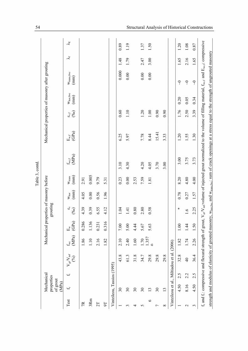
Table 1 : Summary of experimental results: Mechanical properties of three leaf masonry before grouting.
Compressive strength of materials (MPa)
Mechanical properties of masonry
Speci-men
Dimen-sions (m)
Thickness* (m)
Stones/ Bricks
Mortar Filling mate-rial
fwc (MPa)
Ew (GPa)
εv
(‰) whor
(mm) wtrans
(mm)
Toumbakari (2002) SC1 0.6x1.2 0.13/0.14/0.13 55 3.4 1.0 2.02 0.72 1.42 2.89 5.5 SC2 0.6x1.2 0.13/0.14/0.13 55 3.4 1.0 2.09 1.14 1.65 6.90 7.0 SC3 0.6x1.2 0.13/0.14/0.13 55 3.4 1.0 2.65 1.37 1.73 3.63 4.7 SC4 0.6x1.2 0.13/0.14/0.13 55 3.4 1.0 2.71 1.44 2.11 2.84 3.4 BC2 0.6x1.2 0.09/0.22/0.09 25 3.4 1.0 2.41 0.73 3.12 7.07 8.5 BC3 0.6x1.2 0.09/0.22/0.09 25 3.4 1.0 2.09 1.02 1.85 2.69 6.0 BC4 0.6x1.2 0.09/0.22/0.09 25 3.4 1.0 2.18 1.10 2.34 2.32 7.3 BC5 0.6x1.2 0.09/0.22/0.09 25 3.4 1.0 2.28 1.14 2.31 2.00 5.5 Valluzzi (2003) 4X 0.8x1.4 0.18/0.14/0.18 164 1.58 1.83 0.18 6.05 3.44 4.60 6I1 0.8x1.4 0.18/0.14/0.18 164 1.58 2.16 0.31 4.57 0.62 9.17 5I1m 0.8x1.4 0.18/0.14/0.18 164 1.58 1.60 0.37 1.63 0.16 0.66 1I2 0.8x1.4 0.18/0.14/0.18 164 1.58 2.18 0.22 6.21 1.61 3.97 8I2 0.8x1.4 0.18/0.14/0.18 164 1.58 2.12 0.24 6.22 2.20 5.89 7R 0.8x1.4 0.18/0.14/0.18 164 1.58 1.86 0.29 4.39 4.05 2.91 3Rm 0.8x1.4 0.18/0.14/0.18 164 1.58 1.10 1.14 0.39 0.00 0.00 2T 0.8x1.4 0.18/0.14/0.18 164 1.58 2.16 0.23 6.55 0.56 9.79 9T 0.8x1.4 0.18/0.14/0.18 164 1.58 1.82 0.32 4.12 1.96 5.31 Vintzileou and Tassios (1995) 1** 0.6x1.2 0.13/0.14/0.13 100 1.70 0.15 2.10 7.00 1.04 0.23 2 0.6x1.2 0.13/0.14/0.13 100 1.70 0.15 1.30 2.71 2.27 3** 0.6x1.2 0.13/0.14/0.13 100 1.70 0.15 2.40 5.00 1.41 0.00 4 0.6x1.2 0.13/0.14/0.13 100 1.70 0.15 1.60 4.42 0.80 2.53 5 0.6x1.2 0.13/0.14/0.13 100 1.70 0.15 1.70 5.67 2.80 7.59 6 0.6x1.2 0.13/0.14/0.13 100 1.70 0.15 1.35 5.63 0.58 1.81 7 0.6x1.2 0.13/0.14/0.13 100 1.70 0.15 8 0.6x1.2 0.13/0.14/0.13 100 1.70 0.15 Vintzileou et al. (2006) 1 1.0x1.2 0.19/0.12/0.14 25 4.35 0.15 1.82 1.00 - 0.78 8.20 2 1.0x1.2 0.19/0.12/0.14 25 4.35 0.15 1.74 1.44 1.6 0.27 4.80 3 1.0x1.2 0.19/0.12/0.14 25 4.35 0.15 2.26 1.50 2.25 1.57 4.00 * Thickness of external leaf/filling material/external leaf ** Walls with transverse leaves of masonry (i.e. masonry pier with a core of infill material) fwc: compressive strength of masonry, Ew: modulus of elasticity at 30% to 60% of fwc, εv: vertical strain at fwc, whor: sum of vertical cracks opening on the faces (measured at mid-height of the wall), wtrans: sum of the vertical cracks in the transverse direction (measured at mid-height of the wall)
Finally, although the number of available test results is not very large, one may observe that
the improvement of mechanical properties of the filling material is not proportional to the me-chanical properties of the injected grout. This feature will be discussed in the following section.

Elizabeth Vintzileou 51
Miltiadou (1990) has injected cylinders made of mortar (diameter/height = 40/100 mm) with a grout of compressive strength equal to 30.0 MPa. Practically all visible pores of the mortar were filled with grout (porosity changed from 33% to 22%) and its compressive strength in-creased from 7.3 MPa (at 28 days) to 31.0 MPa after grouting. Therefore, this is another contri-bution of grouting to the improvement of the mechanical properties of masonry.
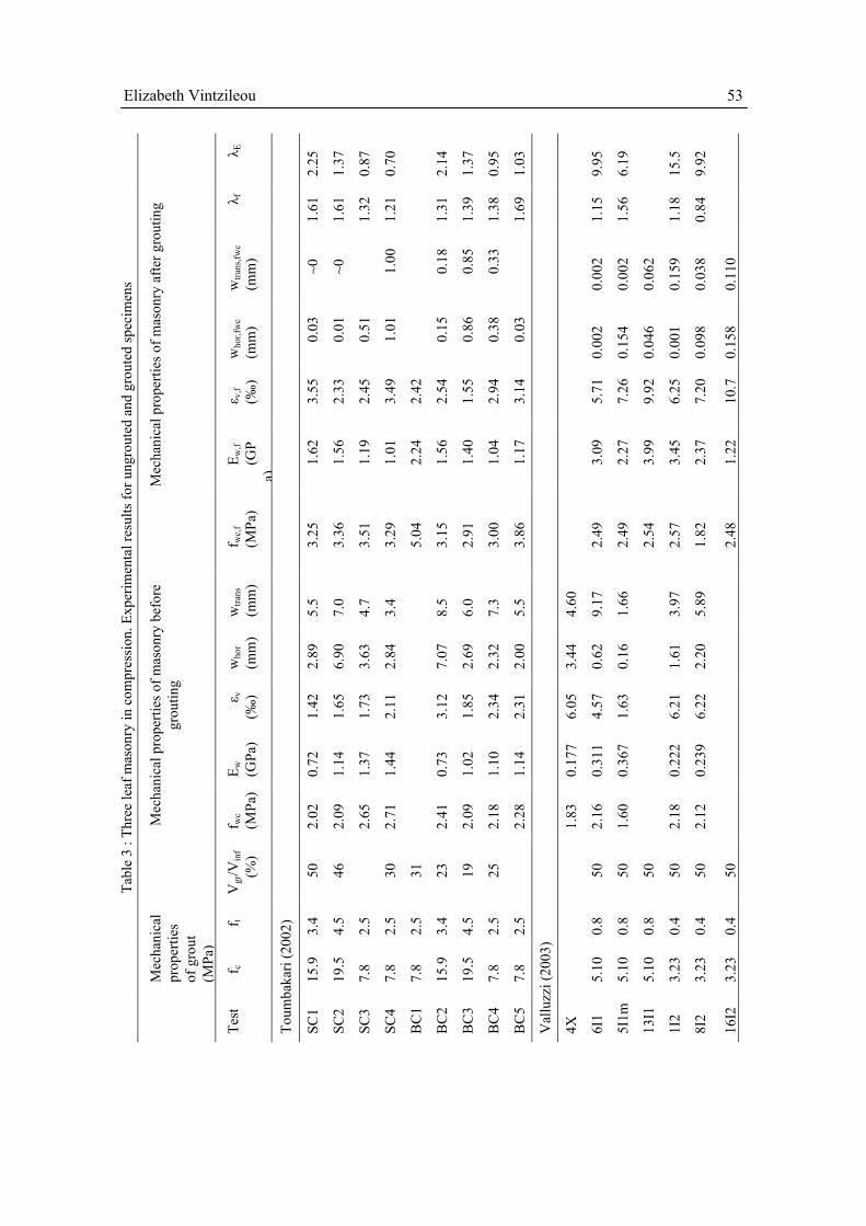
4.3 Properties of grouted masonry in compression In Table 3, a summary of results from testing grouted three leaf masonry specimens is pre-sented. Before trying to compare the values of strength and modulus of elasticity enhancement, one should mention that as reported by all researchers, the behaviour of the specimens they tested present some common characteristics that are independent of the construction type of ma-sonry, of the initial mechanical properties of masonry, as well as of the mechanical properties of the injected grout.
Table 2 : Summary of experimental results on the mechanical properties of ungrouted and grouted filling
material.
Mechanical prop-erties of un-grouted cylinders
Mechanical proper-ties of grout
Mechanical properties of grouted cylinders
Test fc (MPa)
E (GPa)
fg (MPa) fgt (MPa)
fc,in (MPa)
Ein (GPa)
λf λE
Valluzzi (2004)* C7-C8 (0.15) 3.23 0.35 0.82 0.343 (5.47) C9-10(A) (0.15) 3.23 0.35 0.80 0.245 (5.33) C11-C12 (0.15) 5.10 1.99 1.518 (13.27) C13(A) (0.15) 5.10 2.15 1.201 (14.33) C14-C15 (0.15) 3.21 1.43 1.499 (9.53) C17-C18 (0.15) 3.65 1.38 1.253 (9.20) C27-C28 (0.15) 3.35 1.71 1.747 (11.40) C26(A) (0.15) 3.35 1.39 1.354 (9.27)
Miltiadou (1990) 1.71 3.87 30.00** 2.50 13.4 20.45 7.84 5.28
30.00*** 2.50 17.0 15.30 9.94 3.95 Voids
32% 13.00** 1.40 9.5 19.80 5.56 2.45
0.48 1.10 30.00** 2.50 8.8 13.70 18.33 12.45 30.00*** 2.50 10.5 10.5 21.87 9.55
Voids 40%
13.00** 1.40 16.3 16.60 33.95 15.10 NTUA/DTRR-HMC (work in progress)**** T 0.15 10.58 3.13 3.24 21.6 NHL5+SP
0.15 6.36 3.87 2.79 18.6
NHL5 0.15 (6.50) 3.27 21.8 * Percentage of voids~40% ** Injection of undamaged cylinders *** Injection of pre-damaged cylinders **** Average percentage of voids: T (7 cylinders)=39.5%, NHL5+SP (5 cylinders)=42.2%,
NHL5 (6 cylinders)=41.30% fc, E: compressive strength and modulus of elasticity of the ungrouted cylinder, fg and fgt: compressive and flexural strength of the grout fc,in and Ein: compressive strength and modulus of elasticity of the grouted cylinder λf= fc,in/ fc, λE=Ein/E
The mode of failure of grouted specimens was essentially the same as for the ungrouted ones.
In fact, vertical cracks have opened on the two faces of wallettes. Some of the cracks formed during loading before grouting have opened again, whereas in many cases, new cracks did also
52 Structural Analysis of Historical Constructions
appear. Furthermore, vertical cracks separating the three leaves were formed in the transverse direction. Nevertheless, a substantial increase of the compressive strength was recorded. This is because (independently of the strength of the grout) the grouted masonry remains free of verti-cal cracks at a stress level equal to the compressive strength of the ungrouted masonry (compare whor and whor,fwc values, wtrans and wtrans,fwc values in Table 3). In fact, as the grout fills the cracks, the voids of the infill material, as well as (partly) the pores of the mortar, homogenization of masonry takes place. The compressive strength and the modulus of elasticity of the (previously very weak) filling material are increased, whereas the bond between the three leaves is en-hanced. Thanks to that, the mechanical properties of each separate leaf are improved, whereas the separation between them is delayed. Thus, the compressive strength of masonry as a whole is increased.
In the tests reported in the literature (Table 3), the compressive strength of the grouts used to inject masonries ranges between 3.23 MPa and 30.00 MPa. The ratio of grouted to ungrouted compressive strength of masonry (λf) ranges between 1.15 and 2.50 only. It seems also that the higher compressive strength of grout does not necessarily lead to higher strength enhancement.
This observation led Vintzileou et al. (1995) to the conclusion that the governing property of the grout is not its compressive strength but its tensile strength rather. Furthermore, it became obvious that the use of high strength grouts (i.e. grouts with high cement content) is not neces-sary.
Miltiadou (1990) had already observed the effect of various parameters on the behaviour of interfaces between binary or ternary cement grouts with cement content 50-75% and substrate, by testing composite specimens either in tension or in shear. She identified the effect of the po-rosity of the substrate, the degree of saturation of the stones, the thickness of the grout joint, as well as the effect of the grout itself. In fact, she measured substantially higher strength of the in-terface (both in shear and tension) for the grouts containing ultra fine materials than for pure cement grout.
Later, Toumbakari (2002), who tested the effect of ternary grouts with lower cement content on the mechanical properties of three leaf masonry, made the working hypothesis that the effect of a grout depends on the bond properties of the interface between the grout and the in situ ma-terials. Shear tests on composite (grout/substrate) specimens have proven that the bonding prop-erties of a grout are not necessarily proportional to its compressive or tensile strength. Toum-bakari found that the presence of ultra fine material (silica fume in the case of her work) led to enhanced strength of grout/substrate interface. Thus, although the grout containing 30% cement (wt) and silica fume was of smaller compressive and tensile strength than the cement grout, it led to similar strength enhancement of the masonry. Recently, Adami et al. (2006a) have tested in direct tension composite specimens made of two pieces of stone or brick connected by a joint of grout. It was found that the grout G2 (cement 30%-lime 35%-metakaolin 35%) having a com-pressive strength of 9.9 MPa at 28 days led to a tensile strength of the joint practically equal to that of the grout G1 (cement 80%- lime 20%) with a compressive strength of 14.60 MPa at 28 days. The favourable effect of the porosity of the substrate was also confirmed. Similar findings are reported in Adami et al. (2006b) from shear tests on composite specimens.
It is believed that the recognition of the role of the bond mechanism on the mechanical prop-erties of grouts is very important for the design and the selection of adequate grouts that may be composed of materials similar to those in situ and very efficient at the same time. In addition, as shown in the data of Table 3, the use of grouts with reduced cement content or the use of hy-draulic lime based grouts does lead to moderate increase of the stiffness of masonry. This is considered to be positive, especially in the case of partial grouting of the masonry in a historic structure, since the flow of forces within the structure is not substantially altered.
Elizabeth Vintzileou 53
λ Ε
2.25
1.37
0.87
0.70
2.14
1.37
0.95
1.03
9.95
6.19
15.5
9.92
λ f
1.61
1.61
1.32
1.21
1.31
1.39
1.38
1.69
1.15
1.56
1.18
0.84
wtra
ns,fw
c (m
m)
~0
~0
1.00
0.18
0.85
0.33
0.00
2
0.00
2
0.06
2
0.15
9
0.03
8
0.11
0
who
r,fw
c (m
m)
0.03
0.01
0.51
1.01
0.15
0.86
0.38
0.03
0.00
2
0.15
4
0.04
6
0.00
1
0.09
8
0.15
8
ε v,f
(‰)
3.55
2.33
2.45
3.49
2.42
2.54
1.55
2.94
3.14
5.71
7.26
9.92
6.25
7.20
10.7
E w,f
(GP
a)
1.62
1.56
1.19
1.01
2.24
1.56
1.40
1.04
1.17
3.09
2.27
3.99
3.45
2.37
1.22
Mec
hani
cal p
rope
rties
of m
ason
ry a
fter g
rout
ing
f wc,
f (M
Pa)
3.25
3.36
3.51
3.29
5.04
3.15
2.91
3.00
3.86
2.49
2.49
2.54
2.57
1.82
2.48
wtra
ns
(mm
)
5.5
7.0
4.7
3.4
8.5
6.0
7.3
5.5
4.60
9.17
1.66
3.97
5.89
who
r (m
m)
2.89
6.90
3.63
2.84
7.07
2.69
2.32
2.00
3.44
0.62
0.16
1.61
2.20
ε v
(‰)
1.42
1.65
1.73
2.11
3.12
1.85
2.34
2.31
6.05
4.57
1.63
6.21
6.22
E w
(GPa
)
0.72
1.14
1.37
1.44
0.73
1.02
1.10
1.14
0.17
7
0.31
1
0.36
7
0.22
2
0.23
9
Mec
hani
cal p
rope
rties
of m
ason
ry b
efor
e gr
outin
g
f wc
(MPa
)
2.02
2.09
2.65
2.71
2.41
2.09
2.18
2.28
1.83
2.16
1.60
2.18
2.12
Vgr
/Vin
f (%
)
50
46
30
31
23
19
25
50
50
50
50
50
50
f t
3.4
4.5
2.5
2.5
2.5
3.4
4.5
2.5
2.5
0.8
0.8
0.8
0.4
0.4
0.4
Mec
hani
cal
prop
ertie
s of
gro
ut
(MPa
)
f c
15.9
19.5
7.8
7.8
7.8
15.9
19.5
7.8
7.8
5.10
5.10
5.10
3.23
3.23
3.23
Tabl
e 3
: Thr
ee le
af m
ason
ry in
com
pres
sion
. Exp
erim
enta
l res
ults
for u
ngro
uted
and
gro
uted
spec
imen
s
Test
Toum
baka
ri (2
002)
SC1
SC2
SC3
SC4
BC
1
BC
2
BC
3
BC
4
BC
5
Val
luzz
i (20
03)
4X
6I1
5I1m
13I1
1I2
8I2
16I2
54 Structural Analysis of Historical Constructions
λ Ε
0.89
1.19
1.37
1.50
1.20
1.08
0.87
λ f
1.48
1.79
2.47
3.00
1.65
2.16
1.65
wtra
ns,fw
c (m
m)
0.00
0
0.00
0.00
0.00
~0
~0
~0
who
r,fw
c (m
m)
0.20
0.05
0.34
ε v,f
(‰)
0.60
1.10
1.20
1.00
0.90
0.90
1.76
2.50
3.39
E w,f
(GPa
)
6.25
5.97
7.78
8.44
15.4
1
3.33
1.20
1.55
1.30
Mec
hani
cal p
rope
rties
of m
ason
ry a
fter g
rout
ing
f wc,
f (M
Pa)
3.10
4.30
4.20
4.05
3.70
3.00
3.00
3.75
3.73
wtra
ns
(mm
)
2.91
0.00
5
9.79
5.31
0.23
0.00
2.53
7.59
1.81
8.20
4.80
4.00
who
r (m
m)
4.05
0.00
0.56
1.96
0.78
0.27
1.57
ε v
(‰)
4.39
0.39
6.55
4.12
1.04
1.41
0.80
2.80
0.58
*
1.6
2.25
E w
(GPa
)
0.28
6
1.13
6
0.23
1
0.31
6
7.00
5.00
4.44
5.67
5.63
1.00
1.44
1.50
Mec
hani
cal p
rope
rties
of m
ason
ry b
efor
e gr
outin
g
f wc
(MPa
)
1.86
1.10
2.16
1.82
2.10
2.40
1.60
1.70
1.
357
0 1.82
1.74
2.26
Vgr
/Vin
f (%
)
43.8
61.3
31.8
34.7
29.8
29.8
29.8
32.8
40
36.4
f t
2.5
2.2
2.5
Mec
hani
cal
prop
ertie
s of
gro
ut
(MPa
)
f c
30
30
30
30
13
30
13
4.50
8.16
4.50
Tabl
e 3,
con
td.
Test
7R
3Rm
2T
9T
Vin
tzile
ou, T
assi
os (1
995)
1 3 4 5
6
7 8 Vin
tzile
ou e
t al.,
Milt
iado
u et
al.
(200
6)
1 2 3 f c an
d f t
: com
pres
sive
and
flex
ural
stre
ngth
of g
rout
, Vgr
/Vin
f:vol
ume
of in
ject
ed g
rout
nor
mal
ized
to th
e vo
lum
e of
filli
ng m
ater
ial,
f wc,
f and
Ew
c,f:
com
pres
sive
stre
ngth
and
mod
ulus
of e
last
icity
of g
rout
ed m
ason
ry, w
hor,f
wc a
nd w
trans
,fwc:
sum
of c
rack
ope
ning
s at a
stre
ss e
qual
to th
e st
reng
th o
f ung
rout
ed m
ason
ry

Elizabeth Vintzileou 55
4.4 The effect of grouting on tensile and shear properties of three leaf masonry The effect of grouting on the shear strength of three leaf masonry was measured either by
testing walls under vertical load and horizontal force (Tomazevic et al. 1982, 1993) or by testing wallettes in diagonal compression (see data of Table 4). As shown in Table 4, although the available results are rather limited in number, it is evident that grouting leads to substantial strength enhancement. In this case as well, it may be observed that the strength increase is not proportional to the compressive or to the tensile strength of the grout.
Similar results were obtained by Tomazevic et al. (1982) who tested a number of walls in shear (under simultaneous vertical load). The masonry was constructed in various ways to simu-late those of historic structures in Slovenia. The walls were grouted with a cement grout. The authors found in most cases an increase of shear resistance varying between 110% and 250%, associated with a rather slight decrease of the horizontal displacement at maximum shear resis-tance (between 10% and 30%). It should be noted that the walls, subjected to cyclic horizontal forces exhibited a quite stable behaviour, without significant force response degradation for im-posed angular distortions up to 1%.
4.5 Grouting of masonry built with clay mortar In many countries all over the world, clay mortar was used for the construction of a large num-ber of structures that survived through decades or centuries and they are to be preserved. This type of poor quality masonry that would par excellence need to be strengthened is, however, the most difficult to be grouted. This is because (a) the size of voids within a clay material being very small (<0.1 mm), it is very difficult for a grout to penetrate and (b) clay may swell when the fluid grout is injected, thus not permitting the grout to further penetrate and fill voids.
To the best of the knowledge of the author, there are no published data regarding this impor-tant issue. However, some unpublished were made available by Miltiadou et al. (2006c) and by Papayianni (2006).
Table 4 : Summary of experimental results: Wallettes subjected to diagonal compression.
Mechanical proper-ties of ungrouted speci-
mens
Mechanical properties of
grout
Mechanical properties of grouted specimens
Speci-men
Dimensions (m)
ft (MPa)
εv (‰)
whor (mm)
fc (MPa)
ft,fl (MPa)
ft,f (MPa)
εv,f (‰)
whor,ft (mm)
λf
Toumbakari (2002) SDC1 0.8x0.8x0.4 0.47 0. 9 0.85 15.9 3.4 0.50 1.36 0.47 1.1 SDC2 0.8x0.8x0.4 0.34 1.2 0.71 19.5 4.5 0.68 1.17 0.05 2.0 SDC3 0.8x0.8x0.4 0.28 1.5 1.20 7.8 2.5 0.59 2.65 0.02 2.1 BDC1 0.8x0.8x0.4 0.44 0.8 0.50 7.8 2.5 0.60 1.56 0.17 1.4 BDC2 0.8x0.8x0.4 0.34 0.3 1.07 15.9 3.4 0.73 1.07 0.02 2.2 BDC3 0.8x0.8x0.4 0.35 0.6 0.50 19.5 4.5 0.75 1.02 0.02 2.1
Vintzileou et al. 1995 9 (0.15) 30 0.64 10 (0.15) 30 0.64
Vintzileou et al., Miltiadou et al. (2006) 4 1.0x1.0x0.45 0.10 2.1 5.2 4.5 2.52 0.22 1.00 0 2.2 5 1.0x1.0x0.45 0.10 1.1 0.2 8.2 2.29 0.34 0.80 0 3.4 6 1.0x1.0x0.45 0.10 1.0 1.5 4.5 2.52 0.23 1.40 0 2.3 ft and εv: tensile strength and respective vertical strain of ungrouted specimen, fc and ft,fl: compressive and flexural strength of grout, ft,f and εv,f: tensile strength and respective vertical strain of grouted speci-men, whor: sum of vertical crack openings on the face of the ungrouted specimen (at ft), whor,ft: sum of vertical crack openings on the face of the grouted specimen (at ft), λf=ft,f/ft
Miltiadou et al., for the needs of strengthening a historic structure made of three leaf stome
masonry with clay mortar (free of material that could swell, however), they have developed a cement/lime/pozzolan grout that should be able to fill as much voids as possible (minimum size

56 Structural Analysis of Historical Constructions
0.2-0.3 mm). They tested the injectability of the grout using the standard test of the sand col-umn, as well as using cylinders with material taken from the structure to be strengthened. The laboratory tests were successful; the site application was successful, as well. However, for the time being, there are no experimental results measuring the improved mechanical properties of the grouted masonry.
Another solution is proposed by Papayianni (2006) for repair or strengthening of adobe struc-tures (Fig. 6): Holes are drilled and a (clay-cement or a clay-lime-pozzolan) grout is introduced with the aim not to fill voids but to form “reinforcement bars”-like stronger zones within ma-sonry. The up to now available results seem to be promising.
Figure 6 : Alternative method for repair/strengthen clay masonry. By courtesy of Papayianni (2006).
5 CONCLUSIONS
The data presented in this paper allow for the following general conclusions to be drawn: 1. Grouting constitutes an intervention technique that may offer a durable and efficient from the
mechanical point of view solution for the preservation of three leaf historic masonries. 2. To this purpose, grouts complying with a set of requirements (physical, chemical and me-
chanical) should be designed. The optimisation of the properties of the grout depends on the characteristics of in situ materials, on the actual state of masonry, on the target and the over-all scheme of the intervention, on the availability of materials and equipment, etc. A rational design of alternative mixes is required. The selection of the mix to be used is based also on laboratory in on site testing.
3. High injectability of the grout must be ensured. The as complete as possible filling of voids is of paramount importance for homogenization of masonry to be achieved.
4. The application procedure is of major importance for the efficiency of grouting and for the protection of architectural and historical elements that are to be preserved.
5. The available experimental results prove that grouting may offer substantial improvement of the behaviour of three leaf masonry in compression, in tension and in shear.
6. It was demonstrated that the governing mechanism for the improvement of behaviour is bond between grout and in situ materials. As the performance of this mechanism is not propor-tional to the compressive or to the tensile strength of the grout itself, grouts made of materi-als similar to the in situ ones, despite their lower mechanical properties, as compared to ce-ment grouts, may be efficient; at the same time they serve better the durability of masonry.
7. There are still several issues that require further research (both experimental and analytical), as shown by the (incomplete though) list that follows: (a) Durability aspects related to the materials used for the grout, (b) Properties of superplasticizers and effect thereof on the properties of the grout, (c) Development of grouts adequate for adobe, as well as for mason-ries made with clay mortar, (d) Thorough study of the bond mechanism between in situ mate-rial and grout and modelling thereof, (e) Testing of three leaf ungrouted and grouted walls under seismic actions, (f) Development of analytical models describing the behaviour of grouted masonry and calibration on the basis of experimental data, with the aim (g) to de-velop models for the design of this intervention.
Elizabeth Vintzileou 57
ACKNOWLEDGMENTS
The contribution of Dr A.Miltiadou-Fezans, Director for Technical Research on Restoration of the Hellenic Ministry of Culture, for the literature she made available to the author and for the critical reading of the text is gratefully acknowledged.
REFERENCES
Adami C.-E., Vintzileou E., Toumbakari E.-E. 2006a. Investigation of the bond mechanism between stones or bricks and grouts. Submitted to the 5th International Seminar on Structural Analysis of His-torical Constructions. New Delhi, India
Adami C.-E., Vintzileou E., Toumbakari E.-E. 2006b. Investigation of the bond mechanism between stones or bricks and grouts. Accepted for the 15th Greek Conference on Concrete (in Greek)
Miltiadou A. 1985. Grouting as a method for the repair of masonry monuments. M.A. Thesis, Institute of Advanced Architectural Studies, University of York, UK.
Miltiadou A., Paillère A.M., Serrano J.J., Denis A., Musicas N. 1989. Formulations de coulis hydrauli-ques pour la réparation et le renforcement des structures et des monuments historiques en maçonnerie. Proceedings of the International Conference on Structural Conservation of Stone Masonry, Athens
Miltiadou, A.E. 1990. Etude des coulis hydrauliques pour la réparation et le renforcement des structures et des monuments historiques en maçonnerie. Thèse de doctorat, Ecole Nationale des Ponts et Chaus-sées, Paris, France. Published in 1991 by LCPC in Collection «Etudes et recherches des Laboratoires des Ponts et Chaussées», série Ouvrages d’art, ISSN 1161-028X, Paris, France
Miltiadou-Fezans, A., Tassios T.P. 2003. Penetrability of Hydraulic Grouts in Structural Strengthening”, in “Structural research. Anniversary volume honouring Peter Lenkei, Edited by Dr. Barsony , Univer-sity of Pecs, Hungary
Miltiadou-Fezans, 2004. Aghia Eirini church, Aiolou str. Athens: Stabilization and restoration. Restora-tion of monuments and revitalization of historic buildings in Athens, J.Kizis (ed.), Vol. 1, 00. 112-135, ERGON Publisher, Athens (in Greek)
Miltiadou-Fezans A., Papakonstantinou E., Zambas K., Panou A., Frantzikinaki K., 2005. Design and application of hydraulic grouts of high injectability for the structural restoration of the column drums of the Parthenon Opisthodomos., Proceedings of STREMA IX, WIT Press, pp. 461-471.
Miltiadou-Fezans A., Vintzileou E., Papadopoulou E., Kalagri A. 2006a. Mechanical properties of three-leaf stone masonry after grouting. Submitted to the 5th International Seminar on Structural Analysis of Historical Constructions. New Delhi, India
Miltiadou-Fezans A., Tassios T.P. 2006b. New rational criteria for the holistic design of hydraulic grouts, 1st Conference of the Society for Research and Promotion of Scientific Restoration of Monuments (in Greek)
Miltiadou-Fezans A., Anagnostopoulou S., Kalagri A. 2006c. Development of grouts for a historic build-ing in the island of Paros, Internal Report, Directorate of Technical Research on Restoration, Hellenic Ministry of Culture (in Greek)
Norme Française P18-891. 1992. Produits spéciaux destinés aux constructions en béton hydraulique-Produits à base de résines synthétiques ou de liants hydrauliques pour injections dans des structures en béton-Essai d’injectabilité à la colonne de sable en milieu sec et/ou humide. Paris, France, 12pp.
NTUA/DTRR-HMC. 2006. Unpublished data of research program, in progress. Paillère A.M., Guinez R. 1984. Recherche d’une formulation de coulis à base de liants hydrauliques pour
l’injection dans les fines fissures et les cavités, Bulletin de liaison des Laboratoires des Ponts et Chaussées, Paris no 130, pp. 51-57
Paillère A.M., Buil M., Miltiadou A., Guinez R., Serrano J.J. 1989. Use of silica fume and superplasticiz-ers in cement grouts for injection of fine cracks, Proceedings of the 3rd International Conference on fly ash, silica fume, slag and natural pozzolans in concrete, Trodheim, Norway, Vol. 2, pp. 1131-1157
Papayianni I. 2006. Personal communication, unpublished data from a Diploma Dissertation (by Tapsas S. and Lolis Ph.-supervised by Papayianni), Aristotle University of Salonica (in Greek)
Tassios,T.P. 2004. Rehabilitation of three-leaf masonry. In Evoluzione nella sperimentazione per le costruzioni, Seminario Internazionale, 26 Sept- 3Oct., Centro Internationale di Aggiornamento Speri-mentale – Scientifico (CIAS)
Tomazevic M., Sheppard P. 1982. The strengthening of stone-masonry buildings for revitalization in seismic regions. 7th European Conference on Earthquake Engineering, Athens, Vol. 5, pp. 275-282
Tomazevic M., Apih V. 1993. The strengthening of stone-masonry walls by injecting the masonry-friendly grouts. European Earthquake Engineering, 1, pp. 10-20
58 Structural Analysis of Historical Constructions
Toumbakari E.-E. 2002. Lime-pozzolan-cement grouts and their structural effects on composite masonry walls. Doctor Thesis, Katholieke Universiteit Leuven
Valluzzi M.-R. 2003. Consolidamento e recupero delle murature. Gruppo Editoriale Faenza Editrice S.p.a, Collana scientifica « Reficere » Ed. Cesare Renzo Romeo, Faenza, Italy.
Valluzzi M.-R. 2004. Consolidamento di murature in pietra, Iniezioni di calce idraulica naturale. Gruppo Editoriale Faenza Editrice S.p.a, Collana scientifica « Reficere » Ed. Cesare Renzo Romeo, Faenza, Italy.
Vintzileou E., Tassios T.P. 1995. Three leaf stone masonry strengthened by injecting cement grouts. Journal of Structural Engineering, ASCE, Vol. 121, No 5, pp. 848-856.
Vintzileou E., Miltiadou-Fezans A., Palieraki V., Delinikolas N. 2004. The use of radar techniques and endoscopy in investigating old masonry: the case of Dafni Monastery. Proceedings of the 4th Interna-tional Seminar on Structural Analysis of Historical Constructions. Modena C., Lourenco P.B., Roca P. (ed.), Rotterdam, Balkema, Vol. 2, pp. 351-360
Vintzileou E., Miltiadou-Fezans A., Vrouva A., Anagnostopoulou S. 2006. Mechanical properties of three-leaf stone masonry. Submitted to the 5th International Seminar on Structural Analysis of Histori-cal Constructions. New Delhi, India