Embed Size (px)
Citation preview

GRP Fl d i & tGRP Flanges design & assessmentRotterdam, 10 March 2011

Scope
1 I t d ti1.Introduction
2.Flange failures & flange design
3.Flange qualification & load assessment methods
4.Present ISO 14692 approach and update
Copyright 2010 © Dynaflow Research Group BV

FRP pipe pressure versus diameter Jointing systems
80
90
100
60
70
80
rg]
. Cemented & Laminated(flanges)
Cemented Laminated RSLJ
40
50
60
Pres
sure
[Bar Cemented, Laminated, RSLJ, Flanges, RSJ, Double Bell couplers
20
30
Des
ign
Double Bell Couplers & Laminations, Flanges
0
10
0 250 500 750 1000 1250 1500 1750 2000 2250 2500 2750 3000 3250 3500 3750 4000
Copyright 2010 © Dynaflow Research Group BV
0 250 500 750 1000 1250 1500 1750 2000 2250 2500 2750 3000 3250 3500 3750 4000Nominal Diameter [mm]

Glass Reinforced Flanges NB 4000 mm
Copyright 2010 © Dynaflow Research Group BVCopyright 2010 © Dynaflow Research Group BV

Shortcomings of present GRP codesShortcomings of present GRP codes
Flange assessment (for combined loading)Flange assessment (for combined loading)
SIF’s and flexibilities
Local Buckling of large bore U/G headers (limited effect of side support)
Interference of underground pipes
A/G supporting of large bore headers
Copyright 2010 © Dynaflow Research Group BV
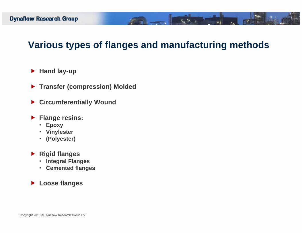
V i t f fl d f t i th dVarious types of flanges and manufacturing methods
Hand lay-upHand lay-up
Transfer (compression) Molded
Circumferentially WoundCircumferentially Wound
Flange resins:EpoxyVinylesterVinylester(Polyester)
Rigid flangesIntegral FlangesIntegral FlangesCemented flanges
Loose flanges
Copyright 2010 © Dynaflow Research Group BV

Copyright 2010 © Dynaflow Research Group BV

Scope
1 I t d ti1.Introduction
2.Flange failures & flange design
3.Flange qualification & load assessment methods
4.Present ISO 14692 approach and update
Copyright 2010 © Dynaflow Research Group BV
Copyright 2010 © Dynaflow Research Group BV

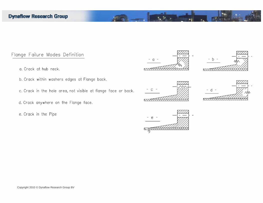
“Crack” in the pipe adjacent to the flangeEXAMPLE
p p j g
Copyright 2010 © Dynaflow Research Group BV

“crack” in the pipe adjacent to the flangeadjacent to the flange
Copyright 2010 © Dynaflow Research Group BV

Crack in the flange faceCrack in the flange face between the bolts and inside the bolt hole
Copyright 2010 © Dynaflow Research Group BV

Crack at the hub neck
Copyright 2010 © Dynaflow Research Group BV 13

Crack at the hub neck
Copyright 2010 © Dynaflow Research Group BV

Sheared flange starting with crack at the neck of the hubg g
Copyright 2010 © Dynaflow Research Group BV

Crack at the hub neck EXAMPLE
Copyright 2010 © Dynaflow Research Group BV

EXAMPLECrack at the hub neck
Copyright 2010 © Dynaflow Research Group BV

“ k” t th “h b k”“crack” at the “hub neck”
Copyright 2010 © Dynaflow Research Group BV

Copyright 2010 © Dynaflow Research Group BV

Intermediate conclusion
C k t th h b k th d i ti f il h iCracks at the hub neck are the dominating failure mechanismCracks at the hub neck are often catastrofic
Copyright 2010 © Dynaflow Research Group BV

Cracks at the hub neck are related to a match-up problem between flange ring and connected pipering and connected pipe
t
kkM
=θ3
,1 **)*( pipepipeaxialpipepipe tEtDfk ≈3
Copyright 2010 © Dynaflow Research Group BV
flangeringpipe kk + 3,2 **),( flangeflangeringntialcircumfereioflangering tEDDfk ≈

Flange design:Flange design:
Delicate balance between:
1. Stiff flange ring (minimizing flange ring rotation)
2. Sufficient strength in transition between flange ring and connected pipe to bridge the deflection difference
Glass-rich area
Flange ring deflection (rotation) governed by moment of inertia around x-axis
Ix ~ h3*Ecirc
Copyright 2010 © Dynaflow Research Group BV
Potentially circumferential glass in a thick flange results in the highest Ix values

Flange Cracking is hindering FRP application and has to be eleminatedFlange Cracking is hindering FRP application and has to be eleminated
G fl f il i i iti t d b k d i t t hiGross flange failure is initiated by cracks and is catastrophic
Flange cracks are relatively common (more common in larger bore flanges)A cracked flange is “normal”gMost cracks are superficial (only in resin rich area and not penetrating into reinforced flange body)
Origin of Flange cracksOrigin of Flange cracksTorque of the boltsExcessive external loads (moments)Application of wrong gasket D f i fl d iDefective flange designDefective flange production
Copyright 2010 © Dynaflow Research Group BV

Superficial cracks ??p
Copyright 2010 © Dynaflow Research Group BV

Superficial cracks ??
Copyright 2010 © Dynaflow Research Group BV

Scope
1 I t d ti1.Introduction
2.Flange failures
3.Flange qualification & load assessment methods
4.Present ISO 14692 approach and update
Copyright 2010 © Dynaflow Research Group BV

Flange Assessment/Design methods:Some only internal pressureExternal loads incorporated as increased internal pressure (equivalent
)pressure)
Dedicated FRP codesASME B&PV Section X
Common Assessment Items:
1.Longitudinal Stress in HubASME B&PV Section XASME RTRP 2.Radial Stress in the flange
3.Tangential/Circumferential Stress in the flange4.Largest combined stress (Hub + Flange)5.Radial stress at the bolt circle
Metal (Isotropic) codes:AD MerkblatterRToD D-0701 Key:EN 13480EN 1591UNI 2231
What is allowable stress??
Depends on location and flange manufacturing method
B d li i ??
Copyright 2010 © Dynaflow Research Group BV
Based on supplier experience??
Based on tests??

Crack at the hub neck due to external moments??
Copyright 2010 © Dynaflow Research Group BV 28

Flange Failure due to external loads?? EXAMPLE
Copyright 2010 © Dynaflow Research Group BV

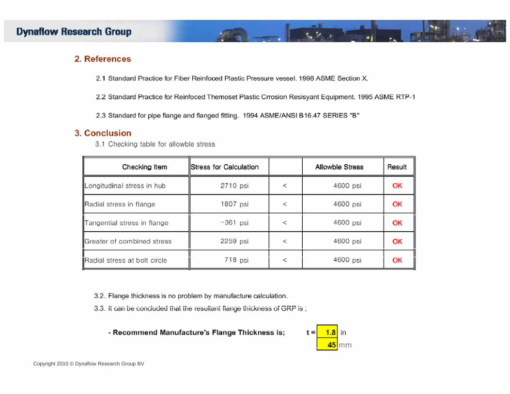
Flange verification:
Conform ASME RTP-1
1. Internal pressure only
2. Allowable stress 4600 psi(supplier experience??)
Copyright 2010 © Dynaflow Research Group BV
Copyright 2010 © Dynaflow Research Group BV

Copyright 2010 © Dynaflow Research Group BV

Copyright 2010 © Dynaflow Research Group BV

E t l fl l d i t tExternal flange loads are important
How to address external loads
1. Present practice incl present issue of ISO 146922. Iso 14692 revision (2011-2012)
Copyright 2010 © Dynaflow Research Group BV

GRP Flange qualification conform current issue of ISO 14692
Flanges qualified byA 1000 hr Qualification tests conform ASTM D1598A. 1000 hr Qualification tests conform ASTM D1598B. Testing conform ASTM D4024 / D5421
Copyright 2010 © Dynaflow Research Group BV
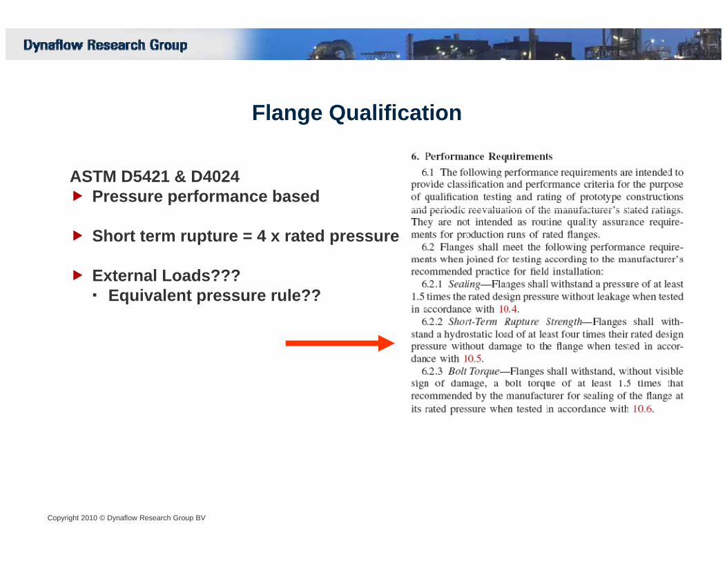
Flange Qualification
ASTM D5421 & D4024ASTM D5421 & D4024Pressure performance based
Short term rupture = 4 x rated pressurep p
External Loads???Equivalent pressure rule??
Copyright 2010 © Dynaflow Research Group BV

External loads incorporated by means of Equivalent pressure rule (ASME B&PV S ti III NC 3658 1 b t l RT D D0701)(ASME B&PV Section III NC 3658.1 but also e.g. RToD D0701)
P + P < P
Copyright 2010 © Dynaflow Research Group BV
Pinternal+ Pequivalent< Prating
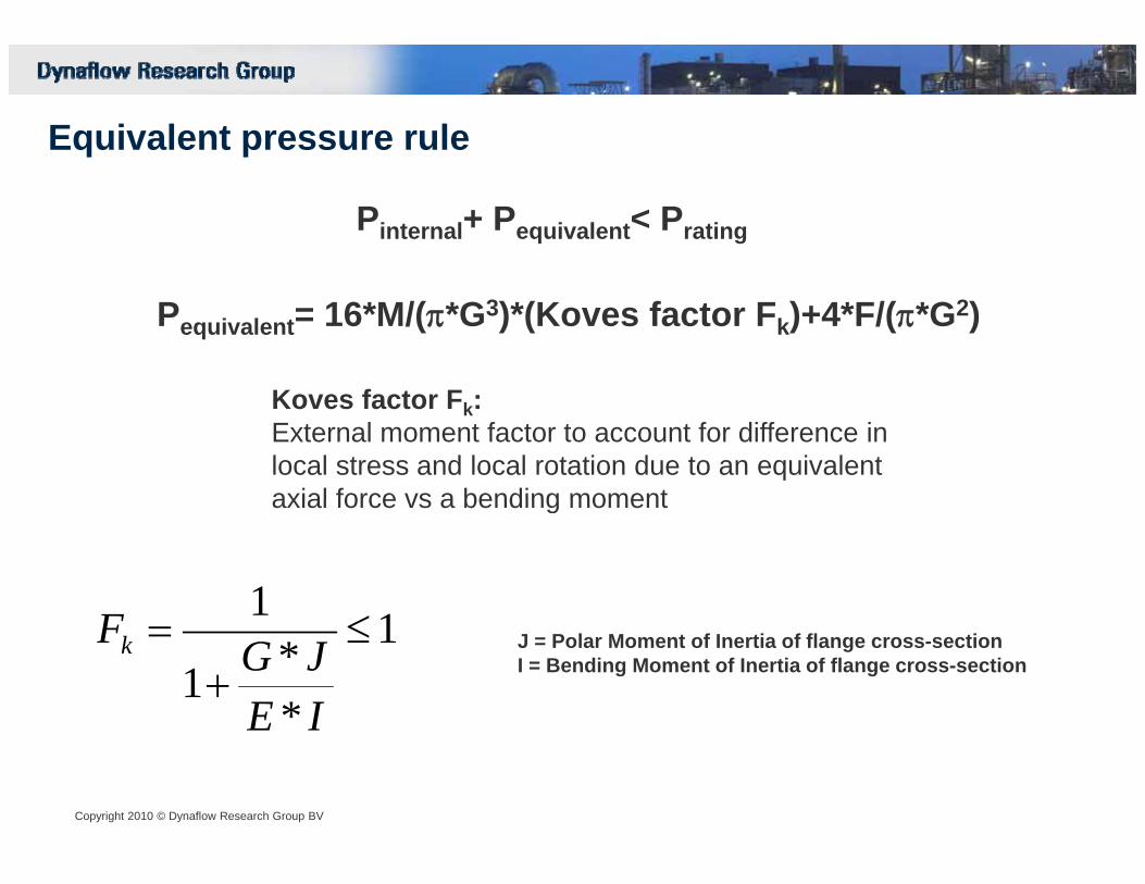
Equivalent pressure rule
Pinternal+ Pequivalent< Prating
Pequivalent= 16*M/(π*G3)*(Koves factor Fk)+4*F/(π*G2)
Koves factor Fk:External moment factor to account for difference in local stress and local rotation due to an equivalent axial force vs a bending momentaxial force vs a bending moment
1J = Polar Moment of Inertia of flange cross-sectionI = Bending Moment of Inertia of flange cross-section
1
**1
1≤
+=
IEJGFk
Copyright 2010 © Dynaflow Research Group BV
IE

T tiTwo questions:
1.Is the equivalent pressure approach also a valid approach for GRP flanges?flanges?
2.Is the Koves factor (smoothing the effect of moment loads) valid for GRP flanges.??
Copyright 2010 © Dynaflow Research Group BV

Compression StressCompression Stress
Copyright 2010 © Dynaflow Research Group BV
Tensile Stress
FE-Check of equivalent pressure rule

Flange failure due to local loading EXAMPLE
Copyright 2010 © Dynaflow Research Group BV

Flange failure due to local loading (fish plates)
Copyright 2010 © Dynaflow Research Group BV

Scope
1 I t d ti1.Introduction
2.Flange failures & flange design
3.Flange qualification & load assessment methods
4.Present ISO 14692 approach and update
Copyright 2010 © Dynaflow Research Group BV

Flange Assessment/Design methods:
Dedicated FRP codesASME B&PV Section XASME RTRP
Common Assessment Items:
1.Longitudinal Stress in Hub2 R di l St i th fl
Metal (Isotropic) codes:AD MerkblatterRToD D-0701EN 13480
2.Radial Stress in the flange3.Tangential/Circumferential Stress in the flange4.Largest combined stress (Hub + Flange)5.Radial stress at the bolt circle
EN 1591UNI 2231
Alternative method:1 Flanges fail d e to strain1. Flanges fail due to strain:Simplified Design Method
Flange rotation criterion: 1 deg.
Copyright 2010 © Dynaflow Research Group BV

Objective of new approach in ISO 14692 revisionObjective of new approach in ISO 14692 revision
F fl f tFor flange manufacturer
Qualification criteria for family representative flangesScaling rules for family member flangesScaling rules for family member flanges
For Engineer
G f fGeneration of allowable flange load envelope
Copyright 2010 © Dynaflow Research Group BV

GRP Flange qualification conform current issue of ISO 14692
Flanges qualified byFlanges qualified byA. 1000 hr Qualification tests conform ASTM D1598B. Testing conform ASTM D4024 / D5421
Note:+ Draw back of qualification method: Internal pressure loading only+ Simulating external loads by increased qualification pressure??
H l h fl f l
Copyright 2010 © Dynaflow Research Group BV
+ How to scale other flanges from test results
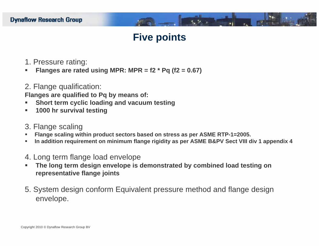
Five points
1. Pressure rating:Flanges are rated using MPR: MPR = f2 * Pq (f2 = 0.67)
2. Flange qualification:Flanges are qualified to Pq by means of:
Short term cyclic loading and vacuum testing1000 hr survival testing
3. Flange scalingFlange scaling within product sectors based on stress as per ASME RTP-1=2005.In addition requirement on minimum flange rigidity as per ASME B&PV Sect VIII div 1 appendix 4
4. Long term flange load envelopeThe long term design envelope is demonstrated by combined load testing on representative flange joints
5. System design conform Equivalent pressure method and flange design envelope.
Copyright 2010 © Dynaflow Research Group BV
p
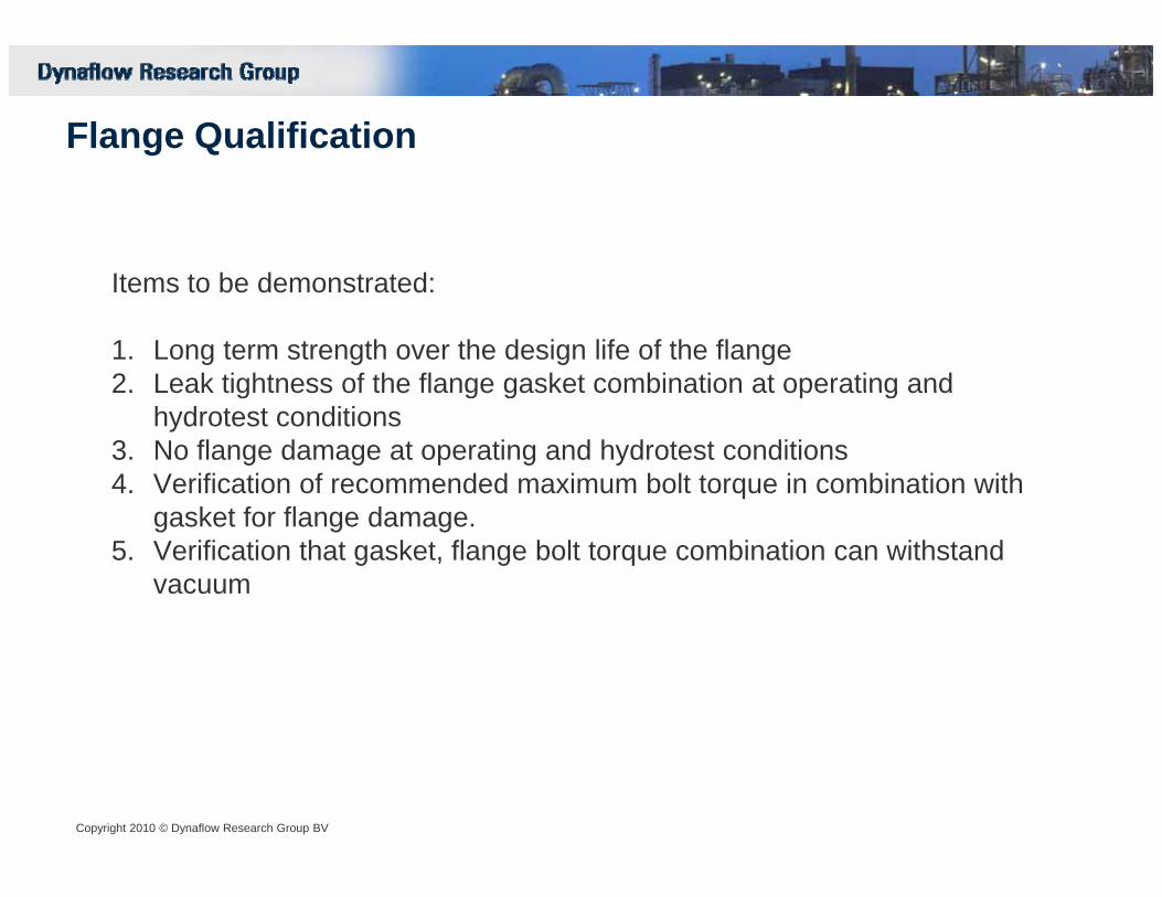
Flange Qualification
It t b d t t dItems to be demonstrated:
1. Long term strength over the design life of the flange 2. Leak tightness of the flange gasket combination at operating and2. Leak tightness of the flange gasket combination at operating and
hydrotest conditions3. No flange damage at operating and hydrotest conditions4. Verification of recommended maximum bolt torque in combination with
f fgasket for flange damage.5. Verification that gasket, flange bolt torque combination can withstand
vacuum
Copyright 2010 © Dynaflow Research Group BV

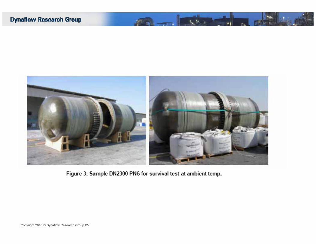
1.Long term strength by means of 1000 hr survival test (Arrangement A) and2 Leak tightness test (Arrangement B)2.Leak tightness test (Arrangement B)
1. In the survival test (at temperature) the flange is allowed to show d b t f il ( l k ) ithi th 1000 hdamage but no failure (e.g. leakage) within the 1000 hr.
2.The leak test (at ambient) is done by 10 pressure cycles for 5 min at 1.5 * MPRFollowed by a vacuum test at -0.5 Barg.
Copyright 2010 © Dynaflow Research Group BV
Followed by a vacuum test at 0.5 Barg.Leakage is considered a test failure.

Applicable 1000 hr test pressureBased on ISO defined fixed ratios typically 2.1-2.7 x MPR
Copyright 2010 © Dynaflow Research Group BV

Copyright 2010 © Dynaflow Research Group BV
Copyright 2010 © Dynaflow Research Group BV

Flange scaling rules
Flange scaling rules are as per ASME RTP-1-2005
Based on dimensions of qualified (family representative) flange representative stress values are determined that can be used in scaling the dimensions of other flanges in the same product sector
The requirement in NM12-370 that the minimum hub thickness is 50% of the flange thickness is dropped because of interference with the bolt circlecircle.
Similar consideration for hub length. Hub length to be based on minimum shear length.
Additional flange rigidity check is added (rigidity index between 1.0 and 1.5 at MPR
Copyright 2010 © Dynaflow Research Group BV

Copyright 2010 © Dynaflow Research Group BV

Copyright 2010 © Dynaflow Research Group BV

Copyright 2010 © Dynaflow Research Group BV

Long term flange envelope
1. Long term flange envelope is demonstrated by supplier by means of 1000 hr combined load tests on a 600 NB and a 1200 NB flanged joint
2. Test to be done at temperature. Therefore if required higher rated gaskets (but of same type) may be used.
3. Two tests: 1. At the 1000 hr qualification pressure & 2. at 25% of the 1000 hr qualification pressure
4. Test data points define the basic envelope that is scaled back to the design envelope by the pressure ratios.
5 If the shape of the en elope for both flanges are eq i alent these5. If the shape of the envelope for both flanges are equivalent these shapes may be scaled to other diameters and pressure classes using the scaling rules.
Copyright 2010 © Dynaflow Research Group BV

Typical flange combined load test set-up
Copyright 2010 © Dynaflow Research Group BV

Test results
Copyright 2010 © Dynaflow Research Group BV

Flange design envelope (conform ISO 14692 revised)
Copyright 2010 © Dynaflow Research Group BV

Default f2 values.
Copyright 2010 © Dynaflow Research Group BV
Thank you
Copyright 2010 © Dynaflow Research Group BV 62
Thank you