Embed Size (px)
Citation preview

Transmitted by Expert from JapanGRRF Informal Group on Automatic Emergency Braking and Lane Departure Warning Systems
25-26 June 2009
y p p Braking and Lane Departure Warning Systems
Items 6.3 to 6.5 of the agenda
Automatic EmergencyAutomatic EmergencyAutomatic Emergency Automatic Emergency Braking Systems (AEBS)Braking Systems (AEBS)g y ( )g y ( )
Explanation of the draft
1

1. Scope1. Scope
AGENDAAGENDAAGENDAAGENDA
-- Vehicle Category Vehicle Category ---- Detection of the Obstacles Detection of the Obstacles ---- Definition of AEBS Definition of AEBS --
2. Specification2. Specification-- Speed Range Speed Range ---- Timing of Braking ControlTiming of Braking Control --Timing of Braking Control Timing of Braking Control -- Requirement of Braking Deceleration Requirement of Braking Deceleration ---- Enhancement of Damage Reducing EffectEnhancement of Damage Reducing Effect ---- Emergency Event Preparation and Collision WarningEmergency Event Preparation and Collision Warning ---- Emergency Event Preparation and Collision Warning Emergency Event Preparation and Collision Warning ---- Prevention of Excessive Dependence to SystemPrevention of Excessive Dependence to System ---- Off SwitchOff Switch --
Othe P incipal Req i ementsOthe P incipal Req i ements-- Other Principal Requirements Other Principal Requirements --3. Test procedures3. Test procedures
-- Test Procedures for Stationary Obstacle Test Procedures for Stationary Obstacle ---- Criteria for Stationary Obstacle Criteria for Stationary Obstacle ---- Verification Test of deactivation of Braking Control to ObstacleVerification Test of deactivation of Braking Control to ObstacleOutside the Test Lane Outside the Test Lane --
2
-- Curved Road Curved Road ---- Functioning Test of the Malfunction Warning Device of AEBS Functioning Test of the Malfunction Warning Device of AEBS --

1. Scope 1. Scope -- Vehicle Category Vehicle Category --1. Scope 1. Scope -- Vehicle Category Vehicle Category --
Thi l ti li t t l f th hi l fThis regulation applies to type approval of the vehicles of categories [M2,M3,N2,N3] * with regard to the Automatic Emergency Braking Systems defined in paragraph 2.3.*: This vehicle of categories shows the proposal of EC. This issue will be discussed in future in the informal meeting and GRRF .
At the time of application of this Regulation, Contracting Parties shall declare that they intend to mandate the installation of AEBS specified in this regulation in their territory for which category of vehicles.
Japan plans to mandate the AEBS installation for the vehicles of categories 1. and 2. as mentioned below. g
1. Vehicles used for the carriage of goods (excluding tractors and trailers) and having a gross vehicle mass exceeding 20 tons.
2. Tractors used for the carriage of goods having a gross vehicle2. Tractors used for the carriage of goods having a gross vehicle mass exceeding 13 tons.
For solving this issue Japan has the idea that the mandated category in thisFor solving this issue, Japan has the idea that the mandated category in this ECE Regulation can be selected by the Contracting Party according to their demand from the traffic accident point of view. Draft : Para. 13

1. Scope 1. Scope -- Detection of Obstacles Detection of Obstacles --1. Scope 1. Scope -- Detection of Obstacles Detection of Obstacles --
i h d i b l h d i fConcerning the detecting obstacles, the detection of a stationary vehicle is also mandated in addition to the moving vehicle detection in this draft.moving vehicle detection in this draft.But at the last brainstorming meeting in December 2008, there was the comment that the requirement of detection
b t l h ld b li it d t th i hi lobstacles should be limited to the moving vehicle.
Therefore, there is an idea of scope in the ECE draft as following.
A) The detection of moving vehicle shall be mandatedA) The detection of moving vehicle shall be mandatedB) The detection of stationary vehicle shall be
optional, but Contracting Party can mandate a p , g ystationary vehicle in its territory.
These issues mentioned above will be discussed in future
4
These issues mentioned above will be discussed in future in the informal meeting and GRRF .

1. Scope 1. Scope -- Definition of AEBS Definition of AEBS --1. Scope 1. Scope -- Definition of AEBS Definition of AEBS --
Definition of Automatic EmergencyDefinition of Automatic Emergency Braking Systems
"Automatic Emergency Braking Systems (hereafter AEBS)"
A) AEBS has functions of the collision warning and the emergency event preparation to the driver in case of occurrence of a danger of collision with a forward obstacle.
B) AEBS has a function of the braking control for mitigating the damage of vehicle
ll h f d b l fcollision with a forward obstacle in case of that collision is judged imminent or
d blDraft : Para. 2.3
unavoidable.5

1. Scope 1. Scope -- Definition of AEBS Definition of AEBS --1. Scope 1. Scope -- Definition of AEBS Definition of AEBS --
z
Collision WarningEmergency Event Preparation
1st StageCollision WarningEmergency Event Preparationg y p
2nd StagegBraking Control for Damage Mitigation
Braking Control for Damage MitigationMitigated Collision
Collision
R d ti f C lli i S d
Collision
Reduction of Collision Speed
6

2. Specification 2. Specification -- Speed Range Speed Range --2. Specification 2. Specification -- Speed Range Speed Range --
Speed RangeThe system need not to start the braking control y gin the following speed ranges.
(a) The vehicle speed is exceeding a maximum speed.p
(b) The absolute speed of the vehicle is equal to or less than 15 km/h./
(c) The relative speed of the vehicle is equal to or less than 15 km/h./
(d) In case of vehicle malfunctions.
7 Draft : Para. 5.6

2. Specification 2. Specification -- Timing of Braking Control Timing of Braking Control --2. Specification 2. Specification -- Timing of Braking Control Timing of Braking Control --
Th t f d iThe most of driver operates the braking or the steering in the normal driving
Mandatory Optional
normal driving.
The most of driver has already operatedhas already operated the braking or the steering in the emergency situation.emergency situation.
A driver can’t avoid the collision even ifthe collision, even if a driver operates the braking or the steering with the
Collision
steering with the maximum vehicle dynamic performance.
The braking control shall be activated.
p
The braking control may be used.8
The braking control shall not be activated.

2. Specification 2. Specification -- Timing of Braking Control Timing of Braking Control --2. Specification 2. Specification -- Timing of Braking Control Timing of Braking Control --
Mandatory OptionalThe most of driver operates the braking or the steering in the
l d i inormal driving.Why is the timing of the braking control prescribed in the regulation?
If AEBS activates in the normal driving DRIVER ACCEPTANCE
condition, a driver has nuisance feeling. • A driver may use off-control. • A driver may have distrust to AEBS• A driver may have distrust to AEBS.And then, AEBS might not activate efficiently in the emergency situation. Draft :efficiently in the emergency situation. Draft :
Para. 5.4
Consideration of driver acceptance is important for
9
p pthe effect of AEBS. Therefore, the timing of the braking control is prescribed in this draft.

2. Specification 2. Specification -- Timing of Braking Control Timing of Braking Control --2. Specification 2. Specification -- Timing of Braking Control Timing of Braking Control --
Operational Range Based on Physical Avoidance LimitOperational Range Based on Physical Avoidance LimitOperational Range Based on Physical Avoidance LimitOperational Range Based on Physical Avoidance LimitOperational Range Based on Physical Avoidance LimitOperational Range Based on Physical Avoidance LimitOperational Range Based on Physical Avoidance LimitOperational Range Based on Physical Avoidance Limit
Operational range based on physical avoidance limit
Collision judgment means a state of a judgment that a collision cannot
p g p yThe timing of the braking control is called collision judgment line in this draft.
Collision judgment means a state of a judgment that a collision cannot be avoided physically by operating either the braking or the steering.
The braking control shall be activated. Draft : Para. 2.10, 5.4.1g
10

2. Specification 2. Specification -- Timing of Braking Control Timing of Braking Control --2. Specification 2. Specification -- Timing of Braking Control Timing of Braking Control --
Driver operates either the braking or the p gsteering for the purpose of avoiding the collision.
Phase 3
PhasePhase 2
Braking SteeringPhase
1
The timing of braking control is prescribed in
11
g g pthis draft based on considering the operation of both the braking and the steering.

2. Specification 2. Specification –– Timing of Braking Control Timing of Braking Control --
Collision Judgment LineCollision Judgment Line
2. Specification 2. Specification –– Timing of Braking Control Timing of Braking Control --
Collision Judgment LineCollision Judgment LineCollision Judgment LineCollision Judgment LineCollision Judgment LineCollision Judgment Line
s]Collision avoidable limit line
by steering
Collision judgment line
TTC[
s
j g
Collision avoidable limit line by braking
Collision avoidable limit lineby steeringy g
Collision avoidable limit line by braking is TTC which is calculated by minimum stopping distance with the braking test.
Collision avoidable limit line by steering is TTC which is calculated by minimum lateral displacement with the steering test.stopp g d sta ce t t e b a g test displacement with the steering test.
Braking: Braking performance of each vehicle is different. Therefore, this line is changed by each vehicle.Therefore, this line is changed by each vehicle.
Steering: TTC = 0.8 (s) fixed value is used for all large trucks.
Draft : Para. 2.8, 2.9, 2.10, 2.11, 5.4.1, 5.4.1.1, 5.4.1.212

From collision judgment line :
2. Specification 2. Specification -- Requirement of Braking Deceleration Requirement of Braking Deceleration --2. Specification 2. Specification -- Requirement of Braking Deceleration Requirement of Braking Deceleration --
From collision judgment line : (a) If the collision avoidable limit by steering is lower than the collision avoidable limit by braking.
Braking control shall be activated with average deceleration of 3.3 m/s2
or more.(b) If the collision avoidable limit by braking is lower than the collision avoidable limit by steering.
Braking control shall be activated (The value of deceleration isn’t prescribed
Collision avoidable limit line
Braking control shall be activated. (The value of deceleration isn t prescribed in this draft, because of short time for braking control.)
Collision avoidable limit lineby steering
Collision avoidable limit line by braking
] by steering
Collision judgment line
Requirement (a)
TTC[
s]
Collision judgment lineRequirement (b)
Draft : Para. 5.5.113

2. Specification 2. Specification -- Requirement of Braking DecelerationRequirement of Braking Deceleration --
Consideration of DelaysConsideration of Delays
2. Specification 2. Specification -- Requirement of Braking DecelerationRequirement of Braking Deceleration --
Consideration of DelaysConsideration of DelaysAEBS has the time delay shown in the Consideration of DelaysConsideration of DelaysConsideration of DelaysConsideration of Delays
TTC(Time to Collision)If a braking control based on th lli i j d t
AEBS has the time delay shown in the figure below. This time delay was considered in this draft.
TTC(Time to Collision)
CollisionUnavoidable Condition
=0.8secExist Danger of Collision
Collision Warning and Event Preparation
Must Initiation
the collision judgment line(TTC=0.8s), the start timing of braking control from the collision judgment
Time
AEBS Initiation
Collision Warning and Event Preparation
Depend on
Enhance Damage Reducing Effect(Earlier Initiation)
from the collision judgment line may be delayed 0.3s.
TTC:0.5s = 0.8s – 0.3s
Brake Line Pressure Target Deceleration
Depend onCharacteristic of Brake Actuator
From Collision judgment line :
When the relative speed is 60km/h or less(Refer page 19)
Vehicle DecelerationPad Clearance
Square:
j gBraking shall be operated with average deceleration of 3.3 m/s2 and 0.5s or mo eSpeed Reduction
+ =+ 0.3 seconds (Total delay time)
more.
( y )
Draft : Para. 5.5.1Computing TimeFor Collision Forecast
Actuator Response Time
Response time to target deceleration
14

2. Specification 2. Specification -- Enhance Damage Reducing Effect Enhance Damage Reducing Effect --
Operational Range Based on Driver’s Normal Maneuvers LimitOperational Range Based on Driver’s Normal Maneuvers Limit
2. Specification 2. Specification -- Enhance Damage Reducing Effect Enhance Damage Reducing Effect --
Operational Range Based on Driver’s Normal Maneuvers LimitOperational Range Based on Driver’s Normal Maneuvers LimitOperational Range Based on Driver s Normal Maneuvers LimitOperational Range Based on Driver s Normal Maneuvers LimitOperational Range Based on Driver s Normal Maneuvers LimitOperational Range Based on Driver s Normal Maneuvers Limit
Operational range based on driver’s normal maneuverslimitThe timing of the braking control is called collision risk judgment line in this draft.
Collision risk judgment means a state that has a risk of a collision. The most of driver has already operated the braking or the steering in the emergency situation.emergency situation.
The braking control may be used by manufacture.Draft : Para. 2.14, 5.4.2
15

2. Specification 2. Specification -- Enhance Damage Reducing Effect Enhance Damage Reducing Effect --
Operational Range Based on Driver’s Normal Maneuvers LimitOperational Range Based on Driver’s Normal Maneuvers Limit
2. Specification 2. Specification -- Enhance Damage Reducing Effect Enhance Damage Reducing Effect --
Operational Range Based on Driver’s Normal Maneuvers LimitOperational Range Based on Driver’s Normal Maneuvers Limit
Expanded range
The most of driver has already operated the braking and the
Operational Range Based on Driver s Normal Maneuvers LimitOperational Range Based on Driver s Normal Maneuvers LimitOperational Range Based on Driver s Normal Maneuvers LimitOperational Range Based on Driver s Normal Maneuvers Limit
The most of driver has already operated the braking and the steering in the emergency situation.
The most of driver operates the
衝突可能性判断ライン
n (T
TC)
The most of driver operates the braking and the steering in the normal driving.(Normal driving area)
L li it li f lli i
Collision risk judgment line
衝突判断ライン
me
to c
ollis
ion Lower limit line for collision
avoidance by normal steering
Collision judgment lineExpanded range
Tim
Collision avoidable limit line by steering
A driver can’t avoid the collision, if d i t th
j g
(Collision risk area)
Draft : even if a driver operates the braking and the steering with the maximum vehicle dynamic performance.(Collision area)
Para. 2.12, 2.13,
Relative velocity2.14 , 2.1516 Braking control may start functioning in the collision risk area.

2. Specification 2. Specification -- Enhance Damage Reducing Effect Enhance Damage Reducing Effect ––
Collision Risk Judgment LineCollision Risk Judgment Line
2. Specification 2. Specification -- Enhance Damage Reducing Effect Enhance Damage Reducing Effect ––
Collision Risk Judgment LineCollision Risk Judgment LineCollision risk judgment line is the lowest limit of drivers’ normal avoiding maneuver.
B ki TTC 0 0317 R +1 54
gggg
Braking: TTC = 0.0317×Rv+1.54Steering: TTC = 1.6 (s)
Rv : Relative velocity
(If the AEBS can detect the overlapping ratio, This draft permit to change TTC=1.6s.)
The steering timing for collision avoidance in large trucks
The braking timing for collision avoidance in large trucks
p g )
Lower limit line for collision avoidance by normal braking
Lower limit line for collision avoidance by normal steering
Confirmed by real world operationCollision risk judgment line
Draft : Para. 2.12, 2.13, 2.14 , 2.15, 5.4.2, 5.4.2.1, 5.4.2.217

2. Specification 2. Specification -- Enhance Damage Reducing Effect Enhance Damage Reducing Effect --
Collision Risk Judgment LineCollision Risk Judgment Line
2. Specification 2. Specification -- Enhance Damage Reducing Effect Enhance Damage Reducing Effect --
Collision Risk Judgment LineCollision Risk Judgment LineCollision Risk Judgment LineCollision Risk Judgment Line
Overlapping RatioOverlapping Ratio
Collision Risk Judgment LineCollision Risk Judgment Line
Overlapping RatioOverlapping Ratio
Lateral Distance for Collision Avoidance (B) = Overlapping Ratio x Vehicles Overall Width (A)
A
B
Lateral Distance for Collision Avoidance
Vehicles Overall Width
A
Steering: TTC = 1.6 (s)AB Ratio gOverlappin =
If the AEBS can detect the overlapping ratio
A
If the AEBS can detect the overlapping ratio, TTC can be increased by the overlapping ratio.
Draft : Para. 2.19, 5.4.2.218
2. Specification 2. Specification -- Enhance Damage Reducing Effect Enhance Damage Reducing Effect --
Speed Range for Expanded RangeSpeed Range for Expanded Range
2. Specification 2. Specification -- Enhance Damage Reducing Effect Enhance Damage Reducing Effect --
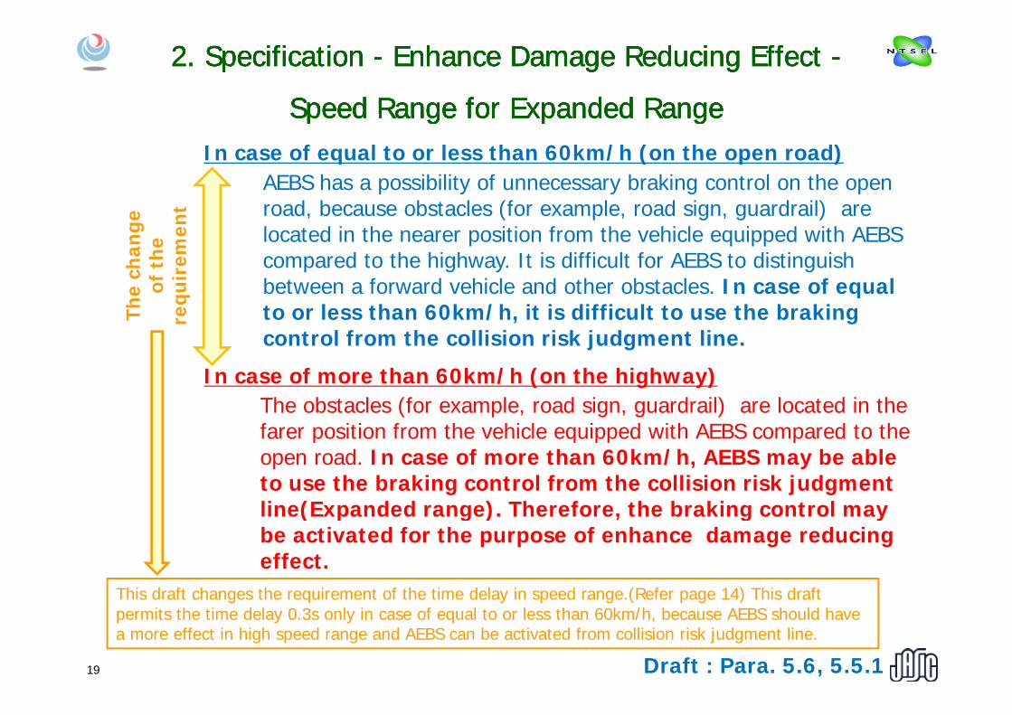
Speed Range for Expanded RangeSpeed Range for Expanded RangeIn case of equal to or less than 60km/h (on the open road)
AEBS has a possibility of unnecessary braking control on the open
Speed Range for Expanded RangeSpeed Range for Expanded RangeSpeed Range for Expanded RangeSpeed Range for Expanded Rangech
ange
f
the
irem
ent road, because obstacles (for example, road sign, guardrail) are
located in the nearer position from the vehicle equipped with AEBS compared to the highway. It is difficult for AEBS to distinguish
The
cof
requ
i between a forward vehicle and other obstacles. In case of equal to or less than 60km/h, it is difficult to use the braking control from the collision risk judgment line.
In case of more than 60km/h (on the highway)The obstacles (for example, road sign, guardrail) are located in the farer position from the vehicle equipped with AEBS compared to the a e pos t o o t e e c e equ pped t S co pa ed to t eopen road. In case of more than 60km/h, AEBS may be able to use the braking control from the collision risk judgment line(Expanded range). Therefore, the braking control may ( p g ) , g ybe activated for the purpose of enhance damage reducing effect.
This draft changes the requirement of the time delay in speed range.(Refer page 14) This draft
19 Draft : Para. 5.6, 5.5.1
g q y p g ( p g )permits the time delay 0.3s only in case of equal to or less than 60km/h, because AEBS should have a more effect in high speed range and AEBS can be activated from collision risk judgment line.

2. Specification 2. Specification -- Enhance Damage Reducing Effect Enhance Damage Reducing Effect --
Requirement of Braking DecelerationRequirement of Braking Deceleration
2. Specification 2. Specification -- Enhance Damage Reducing Effect Enhance Damage Reducing Effect --
Requirement of Braking DecelerationRequirement of Braking DecelerationFrom collision risk judgment line : Braking control may be activated. Deceleration is not specified.
Requirement of Braking DecelerationRequirement of Braking DecelerationRequirement of Braking DecelerationRequirement of Braking Deceleration
g y p
Braking control may be activated in this range.
Draft : Para. 5.5.220

2. Specification 2. Specification –– Summary of Braking Control Timing Summary of Braking Control Timing and Braking Deceleration Requirement and Braking Deceleration Requirement --
2. Specification 2. Specification –– Summary of Braking Control Timing Summary of Braking Control Timing and Braking Deceleration Requirement and Braking Deceleration Requirement --
From collision judgment line :(a)* If the collision avoidable limit by steering is lower than the collision avoidable limit by brakingavoidable limit by braking.
Braking control shall be activated with average deceleration of 3.3 m/s2 or more.
(b) If the collision avoidable limit by braking is lower than the collision avoidable limit by steeringavoidable limit by steering.
Braking control shall be activated.
From collision risk judgment line : (c) Braking control may be activated. Deceleration is not specified(c) specified.
(a)(b)
(c)*: Only equal to or less than 60km/h, if a braking control based on the collision risk judgment line has not been operated, the time delay 0.3s is
Draft : Para. 5.4, 5.521
permitted. This means that collision judgment line is changed from 0.8s to 0.5s in only equal to or less than 60km/h.

2. Specification 2. Specification -- Emergency Event Preparation Emergency Event Preparation and Collision Warning and Collision Warning --
2. Specification 2. Specification -- Emergency Event Preparation Emergency Event Preparation and Collision Warning and Collision Warning --
“Collision Warning" means a function that alerts the driver to a risk of collision in advance and prompts him/her to make an avoiding action.
“Emergency Event Preparation" means a function that notices the driver in advance that the system detects an unavoidable collision and starts controlling the brake system.system detects an unavoidable collision and starts controlling the brake system.
“Collision Warning Braking" means a function that alert the driver a risk of collision by the braking. Its maximum deceleration is 0.98 m/s2 to 2.45 m/s2, and the time of continuation is less than 0.8 seconds.Emergency event C lli i
The braking control
Emergency event preparation
Emergency event preparation shall start until this timing
- 0.8 sActivation
Collision
The braking control from collision judgment line
Activation
Time [s]Collision warning
Collision warning
- 0.8 s
Collision warningshall start until this timing
Activation
Emergency event preparation *
Collision
Activation
The braking control from collision judgment line
The braking control from collision risk judgment line
0.8 s
Time [s]
Activation
*: Collision warning is considered as emergency
Activation
Time of 0.8 (s)(real-time) is based on the reaction time of driver.
Draft : Para. 5.7
22
Time [s]*: Collision warning is considered as emergency event preparation by continuing until collision

2. Specification 2. Specification -- Prevention of Excessive Prevention of Excessive Dependence to System Dependence to System --
2. Specification 2. Specification -- Prevention of Excessive Prevention of Excessive Dependence to System Dependence to System --
Absolute entrustment in the system(T h f ith i th t )
If the vehicle stopped with AEBS
Automatic Emergency Braking Systems will
be automatically activated.
I can stop without
(Too much faith in the system)Truck driver
z
CollisionI can stop without crash, even if I don’t
operate the brake pedal !
The AEBS shall be so designed that the driver does not rely on the system function excessively. y y
For example, a collision is not completely avoided except when the forward obstacle makes a rapid acceleration.forward obstacle makes a rapid acceleration.
If the test vehicle collides or becomes the state considered that it collides with the forward obstacle after activation of AEBS in a test
Draft : Para. 5.8
collides with the forward obstacle after activation of AEBS in a test, this requirement is considered to be satisfied.
23

2. Specification 2. Specification -- Off Switch Off Switch --2. Specification 2. Specification -- Off Switch Off Switch --
If a “AEBS Off” control is provided to stop the activation of theIf a AEBS Off control is provided to stop the activation of the AEBS temporarily in a situation such as a vehicle malfunction, the “AEBS Off” control shall comply with the following requirements.
1 Wh th ti ti f th AEBS i d d bl b th “AEBS1. When the activation of the AEBS is rendered unable by the “AEBS Off” control, the driver in the driver’s seat shall be warned by the optical warning signal indicating such situation.
2. The vehicle's AEBS system shall always return to the “On” mode at the initiation of each new ignition cycle.
3. To prevent any situation in which the AEBS does not function in p ynormal driving caused by misusing of the “AEBS Off” control, it shall have a structure that the driver in the driver’s seat cannot operate it easily. The “AEBS Off” control located in a place not easily reachedeasily. The AEBS Off control located in a place not easily reached by the driver in the driver’s seat is considered to be a structure that the driver in the driver’s seat cannot operate it easily.
4 The vehicle manufacturers shall inform vehicle users through user’s4. The vehicle manufacturers shall inform vehicle users through user s manual that the “AEBS Off” control shall only be used when necessary to cancel the AEBS temporarily in an exceptional situation s ch as a ehicle malf nction so the “AEBS Off” cont ol shall not be
24
such as a vehicle malfunction, so the “AEBS Off” control shall not be used in normal driving.
Draft : Para. 5.12

2. Specification 2. Specification -- Other Principal Requirements Other Principal Requirements --2. Specification 2. Specification -- Other Principal Requirements Other Principal Requirements --
Fail safe function
The system shall have a function to monitor the operating state of the system, and shall detect failures by means of this function.
Draft : Para. 5.9
detect failures by means of this function.
If any failure has occurred in the system, the operation of the system shall stop safely and the system shall return to its basic (manual) braking function as a brake system.
M lf ti t ll t l D ft P 5 9Malfunction tell-tale
If any failure occurs with the system, a visual alarm shall be given.
Indication of over limit of function Draft : Para. 5.11
Draft : Para. 5.9
Indication of over limit of function
If AEBS recognizes an unfavorable situation which precludes its operation, such as when the system detects contamination on the forward obstacle sensor, the driver in the driver’s seat shall be warned by an optical warning indicating that AEBS is not able to
Draft : Para. 5.11
driver s seat shall be warned by an optical warning indicating that AEBS is not able to function.
Driver override
D i id i ’t i hibit d i thi d ft Th t h th id tifi d
Draft : Para. 5.10
Driver override isn’t inhibited in this draft. The system may have the means as identified by the vehicle manufacture to override the braking control.
When the braking control of AEBS is activating, if the driver operates the brake system t t b ki f bi th th t b th AEBS th t h ll b thto generate a braking force bigger than that by the AEBS, the system shall obey the driver's operation.
25

3. Test Procedures 3. Test Procedures -- Test Procedures for Stationary Obstacle Test Procedures for Stationary Obstacle --3. Test Procedures 3. Test Procedures -- Test Procedures for Stationary Obstacle Test Procedures for Stationary Obstacle --
Target having equivalent
Measurements:・Distance・Velocity to calculate TTCg g
magnitude of radar reflection to passenger cars(for Millimeter wave sensor)
・Velocity・Deceleration・Collision triggerS d d id t h k・Sound pressure and video to check
the emergency event preparation and the collision warning
The forward obstacle used for the test shall have two reflectors with a radar cross section (RCS)
Test velocity:20,40,80 ±2 [km/h]
with a radar cross section (RCS) of 15 dBsm or less. The position of the reflector shall be decided by a negotiation with a technical
VTR
by a negotiation with a technical service.
Draft : Annex 3 Para. 2Draft : Annex3 Para. 2.326

3. Test Procedures 3. Test Procedures -- Criteria for Stationary Obstacle Criteria for Stationary Obstacle --3. Test Procedures 3. Test Procedures -- Criteria for Stationary Obstacle Criteria for Stationary Obstacle --
T t l it i 80k /hThe earliest start Ave. over 3.3m/s2
Test velocity is 80km/h
In case of AEBS which can’t detect
The braking control shall be activated by collision judgment line.
timing of the braking control by collision risk judgment line.
m/s
2 ]
which can’t detect the overlapping ratio
judgment line.
Collision warning braking may be activated in this area of TTC.
3.3
2 45ratio
n [m
2.45
Dec
ele
1) Requirements of performance
Average deceleration shall be more than 3.3m/s2 in the range of TTC 0.8(s) to 0(s).
0 0.8(s) 1.6(s) TTC
2) The start timing of the braking control by collision risk judgment line.
Deceleration shall be 2.45 m/s2 or less before TTC is 1.6 (s).
And deceleration at the range of 0 98 to 2 45m/s2 shall not continue more than 0 8 (s)And deceleration at the range of 0.98 to 2.45m/s2 shall not continue more than 0.8 (s).
3) Requirements of collision warning braking
Deceleration at the range of 0.98 to 2.45m/s2 shall not continue more than 0.8 (s) in the area of TTC more than 1.6 (s).
And deceleration shall not exceed 2.45m/s2.27

T t l it i 80k /h
3. Test Procedures 3. Test Procedures -- Criteria for Stationary Obstacle Criteria for Stationary Obstacle --3. Test Procedures 3. Test Procedures -- Criteria for Stationary Obstacle Criteria for Stationary Obstacle --Emergency event
Test velocity is 80km/h
In case of AEBS which can’t detect
g ypreparation shall be started until this line.
]which can’t detect the overlapping ratio
Although in the specification on [
m/s
2 ]
TCAlthough in the specification, requirement of emergency event preparation timing shall be 0.8(s) earlier than the start ec
eler
atio TT
0 8( )be 0.8(s) earlier than the start timing of braking control, 0.6(s) was applied as the criteria by the consideration of
0 Time
De 0.8(s)
h fT1T1 – 0.6(s)
ythe response time of millimeter wave sensor (0.2(s)).
Step 1 search for T1Step 2 search for (T1 - 0.6(s))Step 3 confirm the start of the activation of
t ti til (T1 0 6( ))
1) Emergency Event Preparation
emergency event preparation until (T1 - 0.6(s))
The emergency event preparation shall be activated 0.6 (s) earlier than the time when TTC is 0.8(s).
28

T t l it i 80k /h
3. Test Procedures 3. Test Procedures -- Criteria for Stationary Obstacle Criteria for Stationary Obstacle --3. Test Procedures 3. Test Procedures -- Criteria for Stationary Obstacle Criteria for Stationary Obstacle --The timing of (a) or (b)Collision warningTest velocity is 80km/h
In case of AEBS which can’t detect s2
]
(a) or (b) whichever comes earlier.
Collision warning shall be started until this line.
which can’t detect the overlapping ratio
tion
[m/s
TTC2.45 (a):Over 2.45
Dec
eler
at
(b):Over 0.8(s)0.98Step 1 search for (a),(b)Step 2 search for (T1 - 0.8(s))Step 3 confirm the start of the
2) Collision Warning
0 TimeDp
activation of collision warning until (T1 - 0.8(s)) T1T1 – 0.8(s)
2) Collision Warning
a) Time when deceleration exceeds more than 2.45 m/s2.
b) Time when deceleration at the range of 0 98 to 2 45m/s2 continues moreb) Time when deceleration at the range of 0.98 to 2.45m/s2 continues more than 0.8 (s) .
Collision warning shall starts 0.8 (s) earlier than the timing of (a) or (b) whichever comes earlier.
29

3. Test Procedures 3. Test Procedures -- Criteria for Stationary Obstacle Criteria for Stationary Obstacle --3. Test Procedures 3. Test Procedures -- Criteria for Stationary Obstacle Criteria for Stationary Obstacle --
The braking The earliest start timing of the
Ave. over 3.3m/s2
Test velocity is 40km/h
m/s
2 ]
3.3
control shall be activated by collision judgment line.
timing of the braking control by collision risk judgment line.
This criteria is adapted to the t ti f th b ki t l
ratio
n [m
2.45
Collision warning braking may be activated in this area of TTC.
starting of the braking control from collision judgment line. If the braking control is started from collision risk judgment line, then
0 TTC0 ( ) ( )
Dec
ele
1 6( )
collision risk judgment line, then the criteria is adapted to the criteria of test speed 80km/h
1) Requirements of performance
Average deceleration shall be more than 3.3m/s2 in the range of TTC 0.5(s) to 0(s).
0 TTC0.5(s) 0.8(s) 1.6(s)
Average deceleration shall be more than 3.3m/s in the range of TTC 0.5(s) to 0(s).
2) The start timing of the braking control by collision risk judgment line
Deceleration shall be 2.45 m/s2 or less before TTC is 1.6 (s).
And deceleration at the range of 0.98 to 2.45m/s2 shall not continue more than 0.8 (s).
3) Requirements of collision warning braking
D l ti t th f 0 98 t 2 45 / 2 h ll t ti th 0 8 ( ) iDeceleration at the range of 0.98 to 2.45m/s2 shall not continue more than 0.8 (s) in the area of TTC more than 1.6 (s).
And deceleration shall be less than 2.45m/s2.30

3. Test Procedures 3. Test Procedures -- Criteria for Stationary Obstacle Criteria for Stationary Obstacle --3. Test Procedures 3. Test Procedures -- Criteria for Stationary Obstacle Criteria for Stationary Obstacle --Emergency event preparation shall be
Test velocity is 40km/h
/s2 ]
p pstarted until this line.
atio
n [m
/
TTC
Although in the specification, requirement of emergency event preparation timing shall
Dec
eler
a
0.8(s)
p p gbe 0.8(s) earlier than the start timing of braking control, 0.6(s) was applied as the
0 Time
0 8(s)
T1T1 – 0.6(s)Step 1 search for T1St 2 h f (T1 0 6( ))
criteria by the consideration of the response time of millimeter wave sensor.
1) Emergency Event Preparation
Step 2 search for (T1 - 0.6(s))Step 3 confirm the start of the activation of emergency event preparation until (T1 - 0.6(s))) g y p
The emergency event preparation shall be activated 0.6 (s) earlier than the time when TTC is 0.8(s).
2) Collision Warning2) Collision Warning
The collision warning shall be activated in case of the activating of braking control by collision risk judgment line.31

Test velocity is 20km/h
3. Test Procedures 3. Test Procedures -- Criteria for Stationary Obstacle Criteria for Stationary Obstacle --3. Test Procedures 3. Test Procedures -- Criteria for Stationary Obstacle Criteria for Stationary Obstacle --
Th b kiThe earliest start ti i f th
Over 0.98m/s2
Collision judgment line (If the collision avoidable limit by braking is lower than the collision
s2]
The braking control shall be activated by collision judgment line.
timing of the braking control by collision risk judgment line.
/
avoidable limit by steering)
tion
[m/s
2.45
Collision warning braking may be activated in this area of TTC.
3.3
This criteria is adapted to the starting of the braking control from collision
Dec
eler
at 2.45gjudgment line. If the braking control is started from collision risk judgment line, then the criteria is adapted to the criteria of test speed 80km/h
1) Requirements of performance
Deceleration shall reach more than 0 98m/s2 after crossing the collision judgment line
0 TTC
D
1.6(s)criteria of test speed 80km/h
Deceleration shall reach more than 0.98m/s after crossing the collision judgment line.
2) The start timing of the braking control by collision risk judgment line.
Deceleration shall be 2.45 m/s2 or less before TTC is 1.6 (s).
And deceleration at the range of 0.98 to 2.45m/s2 shall not continue more than 0.8 (s).
3) Requirements of collision warning braking
l h f 0 98 2 / 2 h ll h 0 8 ( )Deceleration at the range of 0.98 to 2.45m/s2 shall not continue more than 0.8 (s) in the area of TTC more than 1.6 (s).
And deceleration shall not exceed 2.45m/s2.32

3. Test Procedures 3. Test Procedures -- Criteria for Stationary Obstacle Criteria for Stationary Obstacle --3. Test Procedures 3. Test Procedures -- Criteria for Stationary Obstacle Criteria for Stationary Obstacle --Emergency event preparation shall be
Test velocity is 20km/h
/s2 ]
p pstarted until this line.
ratio
n [m
/
TTC
Although in the specification, requirement of emergency event preparation timing shall b 0 8( ) li h h
Dec
eler
0.8(s)
be 0.8(s) earlier than the start timing of braking control, 0.6(s) was applied as the
it i b th id ti0 TimeT1T1 – 0.6(s)Step 1 search for T1St 2 h f (T1 0 6( ))
criteria by the consideration of the response time of millimeter wave sensor.
1) Emergency Event Preparation
Step 2 search for (T1 - 0.6(s))Step 3 confirm the start of the activation of emergency event preparation until (T1 - 0.6(s))
The emergency event preparation shall be activated 0.6 (s) earlier than the time when TTC is 0.8(s).
2) Collision Warning2) Collision Warning
The collision warning shall be activated in case of the activating of braking control by collision risk judgment line.
33

3. Test Procedures 3. Test Procedures -- Verification Test of deactivation of Verification Test of deactivation of Braking Control to Obstacle Outside of the Test Lane Braking Control to Obstacle Outside of the Test Lane --3. Test Procedures 3. Test Procedures -- Verification Test of deactivation of Verification Test of deactivation of Braking Control to Obstacle Outside of the Test Lane Braking Control to Obstacle Outside of the Test Lane --
The test vehicle shall be driven at 40 ± 2 km/h speed, keeping its centerline on the lane center, from a point at a e ce te , o a po t atleast 60 m before the obstacles outside of the test lane until the vehicle passeslane until the vehicle passes the obstacles. The test shall be repeated three times.
CriteriaCriteria
VTR
AEBS shall not activate any braking control, in the specified number of tests. Provision above is not applied to collision warning brake VTRwarning brake.
Draft : Annex 3 Para. 3, 4.234
3. Test Procedures 3. Test Procedures -- Curved Road Curved Road --3. Test Procedures 3. Test Procedures -- Curved Road Curved Road --
Requirements related to brake system for easing frontal obstacle impact in curved road.
The braking control system for damage mitigation of frontal obstacle impact shall operate normally even in a curved road (example: R380) where a vehicle may run at a high speed(example: R380) where a vehicle may run at a high speed.
This statement indicates a direction of future development, as well as the technology to reduce collision speed by increasing gy p y gaverage deceleration value. In the future, according to the technology circumstances of frontal obstacle detection and other technologies, the specific test methods need to beother technologies, the specific test methods need to be defined.
Draft : Annex 3 Para. 535

3. Test Procedures 3. Test Procedures -- Functioning Test of the Functioning Test of the Malfunction Warning Device of AEBS Malfunction Warning Device of AEBS --
3. Test Procedures 3. Test Procedures -- Functioning Test of the Functioning Test of the Malfunction Warning Device of AEBS Malfunction Warning Device of AEBS --
Control unitForward obstacle sensor
Turn off the ignition switch, then(1) di t t f th l i t t t
Test procedureTest procedure
(1) disconnect a connector of the power supply or input or output port of the control unit(2) disconnect a connector of the power supply or input or output
CriteriaCriteriaport of the forward obstacle sensor
Turn on the ignition switch, then the failure warning optical signal shall be given within 15 seconds. Draft : Annex 536

History of Discussion and Production ofHistory of Discussion and Production ofHistory of Discussion and Production ofHistory of Discussion and Production ofAPPENDIX
Automatic Emergency Braking Systems in JapanAutomatic Emergency Braking Systems in JapanAutomatic Emergency Braking Systems in JapanAutomatic Emergency Braking Systems in Japan
2001 Design principles for ASV systems
2003 Technical guideline for Automatic Emergency Braking Systems2003 Technical guideline for Automatic Emergency Braking Systems
2003 First release of AEBS in passenger cars
2005 Revision of technical guideline for Automatic Emergency Braking SystemsAutomatic Emergency Braking Systems
2006 First release of AEBS in large trucks
2007 Discussion on the technical regulation of Automatic Emergency Braking Systems for Large Truckg y g y g
37

Study of Detailed Design Principles of Study of Detailed Design Principles of ASVASV((Advanced Safety VehicleAdvanced Safety Vehicle))
Study of Detailed Design Principles of Study of Detailed Design Principles of ASVASV((Advanced Safety VehicleAdvanced Safety Vehicle))
APPENDIX
Design Principles of ASV Design Principles of ASV
(( yy ))(( yy ))
(Formulated in the ASV(Formulated in the ASV--2 Project)2 Project)
The concept of driver assistance was formulated for driver loadThe concept of driver assistance was formulated for driver load reduction and accident avoidance assistance technologies in order to facilitate the interpretation of Design Principles of ASV.
38

Study of Guidelines for the Commercialization of Study of Guidelines for the Commercialization of Study of Guidelines for the Commercialization of Study of Guidelines for the Commercialization of APPENDIX
Approach to Brake ControlApproach to Brake Control
yyAutomatic Emergency Braking Systems (1)Automatic Emergency Braking Systems (1)yy
Automatic Emergency Braking Systems (1)Automatic Emergency Braking Systems (1)
Approach to Brake ControlApproach to Brake Control
Brake control by ASV systems is effective in reducing/avoiding collisions.
There is a concern that if braking is automatically applied in a dangerous situation, the driver may neglect to take evasive action he/she should essentially perform (driver overconfidence in the system).
If the Automatic Emergency Braking Systems is designed to brake when it determines that a collision is physically unavoidable, it is assumed the driver will not put too much confidence in the system.*
System starts applying brakes if it determines a collision is unavoidable.- Physical avoidance limit by braking- Physical avoidance limit by steering
Based on the Design Principles of ASV, system issues a warning to alert the driver to take evasive action before it applies brakes.
*This has been verified by a study of drivers’ dependence on ASV systems.
39

Study of Guidelines for the Commercialization of Study of Guidelines for the Commercialization of Study of Guidelines for the Commercialization of Study of Guidelines for the Commercialization of
APPENDIX
H A t ti E B ki S t W kH A t ti E B ki S t W k
yyAutomatic Emergency Braking Systems Automatic Emergency Braking Systems (2)(2)yy
Automatic Emergency Braking Systems Automatic Emergency Braking Systems (2)(2)
How Automatic Emergency Braking Systems WorkHow Automatic Emergency Braking Systems Work
In response to aJust in the nick of In response to a
warning the driver applies brakes
ASV vehicle
time!
Whew, just a small dent
Looking away
If the driver is too
Beware of obstacle!
The on-board system automatically applies brakes
If the driver is too slow to apply brakes…
Inattentive
Brake control
Too late!
Driver fails to notice
Non-ASV vehicle
Driver fails to notice situation and brakes late
40

The State of the Traffic Accident in Japan (1)The State of the Traffic Accident in Japan (1)The State of the Traffic Accident in Japan (1)The State of the Traffic Accident in Japan (1)APPENDIX
Half of Japanese traffic accidents caused by large trucks are the rear-end collisions. (55%)
Rate of fatalities in rear-end collisions is much higher in large trucks.
Automatic Emergency Braking Systems is effective in Japan.
41

The State of the Traffic Accident in Japan (2)The State of the Traffic Accident in Japan (2)The State of the Traffic Accident in Japan (2)The State of the Traffic Accident in Japan (2)APPENDIX
100%
Rate of Rear-end collision(Highway)
100%t
Rate of Rear-end collision(Open road)
nt nt
60%
80%
raff
ic a
ccid
ent
Stationary (Forward vehicle)
60%
80%
raff
ic a
ccid
ent
Stationary (Forward vehicle)
affi
c A
ccid
en
affi
c A
ccid
en
20%
40%
Rate
of t
r
Traveling (Forward vehicle) 20%
40%
Rate
of t
r
Traveling (Forward vehicle)R
ate
of T
ra
Rat
e of
Tra
0%
Death accident
Serious injury
Slight injury0%
Death accident
Serious injury Slight injury
On the highway, many accidents are against traveling vehicles.
On the open road, many accident are against stationary vehicles.
Automatic Emergency Braking Systems should cover the forward vehicle which is travelling and stationary.
42