Embed Size (px)
Citation preview
Cat. No. W476-E1-01
CompoNet Communications Unit
SmartSliceGRT1-CRT
OPERATION MANUAL

SmartSlice GRT1-CRTCompoNet Communications UnitOperation ManualProduced May 2008

iv
Introduction
IntroductionThank you for buying a SmartSlice CompoNet Communications Unit. The CompoNet Communications Unit is an interface unit which complies with the CompoNet standard. It connects SmartSlice I/O Units to a CompoNet Master Unit. Be sure you understand the functions and performance of the Units fully before you use them.
Intended AudienceThis manual is for the personnel below. This personnel must understand electrical systems (must be an electrical engineer or the equivalent).
Personnel responsible for the selection of FA systems Personnel responsible for the designs of FA systems Personnel responsible for the installation of and connections in FA systems Personnel responsible for the management of FA systems
Precaution This manual contains data which is necessary for you to use a CompoNet Communications Unit. Read and understand this manual fully before you use the CompoNet Communications Unit. After you read this manual, keep it in a safe location where it will be available for use when necessary. Be sure that the end user of the CompoNet Communications Unit has this manual.
v
Read and Understand this Manual
vi
Read and Understand this ManualPlease read and understand this manual before using the product. Please consult your OMRON representative if you have any questions or comments.
Warranty and Limitations of Liability
WARRANTY
OMRON's exclusive warranty is that the products are free from defects in materials and workmanship for a period of one year (or other period if specified) from date of sale by OMRON.
OMRON MAKES NO WARRANTY OR REPRESENTATION, EXPRESS OR IMPLIED, REGARDING NON-INFRINGEMENT, MERCHANTABILITY, OR FITNESS FOR PARTICULAR PURPOSE OF THE PRODUCTS. ANY BUYER OR USER ACKNOWLEDGES THAT THE BUYER OR USER ALONE HAS DETERMINED THAT THE PRODUCTS WILL SUITABLY MEET THE REQUIREMENTS OF THEIR INTENDED USE. OMRON DISCLAIMS ALL OTHER WARRANTIES, EXPRESS OR IMPLIED.
LIMITATIONS OF LIABILITY
OMRON SHALL NOT BE RESPONSIBLE FOR SPECIAL, INDIRECT, OR CONSEQUENTIAL DAMAGES, LOSS OF PROFITS OR COMMERCIAL LOSS IN ANY WAY CONNECTED WITH THE PRODUCTS, WHETHER SUCH CLAIM IS BASED ON CONTRACT, WARRANTY, NEGLIGENCE, OR STRICT LIABILITY.
In no event shall the responsibility of OMRON for any act exceed the individual price of the product on which liability is asserted.
IN NO EVENT SHALL OMRON BE RESPONSIBLE FOR WARRANTY, REPAIR, OR OTHER CLAIMS REGARDING THE PRODUCTS UNLESS OMRON'S ANALYSIS CONFIRMS THAT THE PRODUCTS WERE PROPERLY HANDLED, STORED, INSTALLED, AND MAINTAINED AND NOT SUBJECT TO CONTAMINATION, ABUSE, MISUSE, OR INAPPROPRIATE MODIFICATION OR REPAIR.
Read and Understand this Manual
Application Considerations
SUITABILITY FOR USE
OMRON shall not be responsible for conformity with any standards, codes, or regulations that apply to the combination of products in the customer's application or use of the products.
At the customer's request, OMRON will provide applicable third party certification documents identifying ratings and limitations of use that apply to the products. This information by itself is not sufficient for a complete determination of the suitability of the products in combination with the end product, machine, system, or other application or use.
The following are some examples of applications for which particular attention must be given. This is not intended to be an exhaustive list of all possible uses of the products, nor is it intended to imply that the uses listed may be suitable for the products:
• Outdoor use, uses involving potential chemical contamination or electrical interference, or conditions or uses not described in this manual.
• Nuclear energy control systems, combustion systems, railroad systems, aviation systems, medical equipment, amusement machines, vehicles, safety equipment, and installations subject to separate industry or government regulations.
• Systems, machines, and equipment that could present a risk to life or property.
Please know and observe all prohibitions of use applicable to the products.
NEVER USE THE PRODUCTS FOR AN APPLICATION INVOLVING SERIOUS RISK TO LIFE OR PROPERTY WITHOUT ENSURING THAT THE SYSTEM AS A WHOLE HAS BEEN DESIGNED TO ADDRESS THE RISKS, AND THAT THE OMRON PRODUCTS ARE PROPERLY RATED AND INSTALLED FOR THE INTENDED USE WITHIN THE OVERALL EQUIPMENT OR SYSTEM.
vii
Read and Understand this Manual
viii
Disclaimers
CHANGE IN SPECIFICATIONS
Product specifications and accessories may be changed at any time based on improvements and other reasons.
It is our practice to change model numbers when published ratings or features are changed, or when significant construction changes are made. However, some specifications of the products may be changed without any notice. When in doubt, special model numbers may be assigned to fix or establish key specifications for your application on your request. Please consult with your OMRON representative at any time to confirm actual specifications of purchased products.
DIMENSIONS AND WEIGHTS
Dimensions and weights are nominal and are not to be used for manufacturing purposes, even when tolerances are shown.
PERFORMANCE DATA
Performance data given in this manual is provided as a guide for the user in determining suitability and does not constitute a warranty. It may represent the result of OMRON's test conditions, and the users must correlate it to actual application requirements. Actual performance is subject to the OMRON Warranty and Limitations of Liability.
ERRORS AND OMISSIONS
The information in this manual has been carefully checked and is believed to be accurate; however, no responsibility is assumed for clerical, typographical, or proofreading errors, or omissions.
Safety Precautions
Safety Precautions
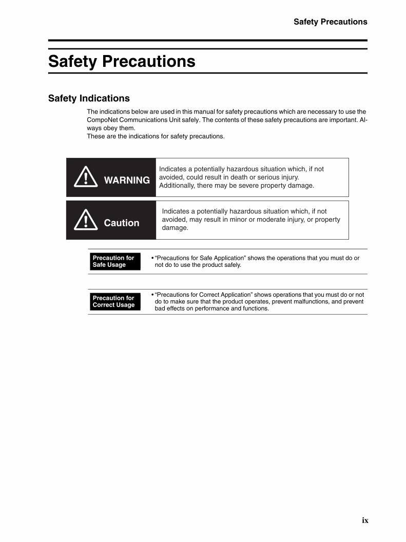
Safety Indications The indications below are used in this manual for safety precautions which are necessary to use the CompoNet Communications Unit safely. The contents of these safety precautions are important. Al-ways obey them. These are the indications for safety precautions.
• “Precautions for Safe Application” shows the operations that you must do or not do to use the product safely.
• “Precautions for Correct Application” shows operations that you must do or not do to make sure that the product operates, prevent malfunctions, and prevent bad effects on performance and functions.
WARNING
Caution
Indicates a potentially hazardous situation which, if not avoided, could result in death or serious injury. Additionally, there may be severe property damage.
Indicates a potentially hazardous situation which, if not avoided, may result in minor or moderate injury, or property damage.
Precaution for Safe Usage
Precaution for Correct Usage
ix

Safety Precautions
x
Descriptions of Symbols
This symbol shows operations that you must not do.
The specified operation shows in the circle. This example shows “do not disassemble.”
This symbol shows precautions (including warnings).
The specified operation shows in the triangle. This example shows a general precaution.
This symbol shows operations that you must do.
The specified operation shows in the circle. This example shows a general precaution for something that you must do.
WARNING
Do not try to disassemble a Unit or touch the terminal block while the power is ON. Doing this can cause electrical shock.
Make sure that the voltage and current input to the Units are in the specified ranges. If the voltage and current are not in the specified ranges, there can be Unit malfunctions or fire.
Turn OFF the I/O power supply to a SmartSlice I/O Unit before you replace it with the online replacement procedure. If there is external power to a terminal for a Relay Output Slave, for example, turn OFF the external power before you replace the SmartSlice I/O Unit. If you replace a Slave I/O Unit with the power ON, incorrect outputs, incorrect inputs, or electric shock can occur.
Safety Precautions
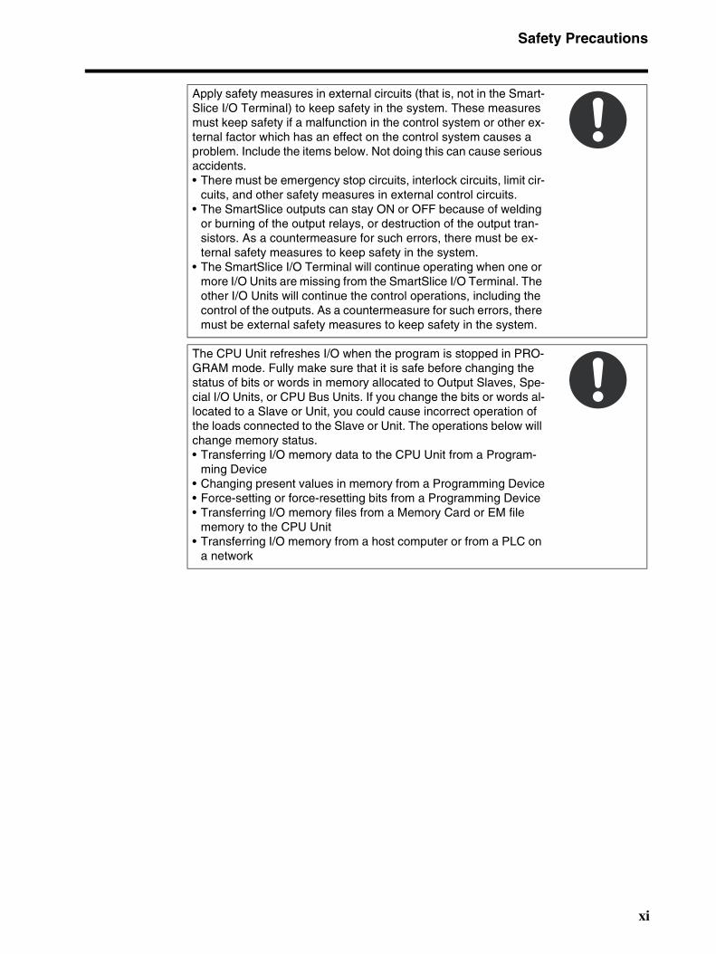
Apply safety measures in external circuits (that is, not in the Smart-Slice I/O Terminal) to keep safety in the system. These measures must keep safety if a malfunction in the control system or other ex-ternal factor which has an effect on the control system causes a problem. Include the items below. Not doing this can cause serious accidents. • There must be emergency stop circuits, interlock circuits, limit cir-
cuits, and other safety measures in external control circuits.• The SmartSlice outputs can stay ON or OFF because of welding
or burning of the output relays, or destruction of the output tran-sistors. As a countermeasure for such errors, there must be ex-ternal safety measures to keep safety in the system.
• The SmartSlice I/O Terminal will continue operating when one or more I/O Units are missing from the SmartSlice I/O Terminal. The other I/O Units will continue the control operations, including the control of the outputs. As a countermeasure for such errors, there must be external safety measures to keep safety in the system.
The CPU Unit refreshes I/O when the program is stopped in PRO-GRAM mode. Fully make sure that it is safe before changing the status of bits or words in memory allocated to Output Slaves, Spe-cial I/O Units, or CPU Bus Units. If you change the bits or words al-located to a Slave or Unit, you could cause incorrect operation of the loads connected to the Slave or Unit. The operations below will change memory status. • Transferring I/O memory data to the CPU Unit from a Program-
ming Device • Changing present values in memory from a Programming Device• Force-setting or force-resetting bits from a Programming Device • Transferring I/O memory files from a Memory Card or EM file
memory to the CPU Unit • Transferring I/O memory from a host computer or from a PLC on
a network
xi
Precautions for Safe Usage
xii
Precautions for Safe Usage • Put a Unit in the special box during transportation. Make sure that the Unit is moved carefully, and
not given too much vibration or shock during transportation.
• Do not let a Unit fall or give it too much vibration or shock. This can cause malfunction or cause damage to the Unit.
• Install the SmartSlice I/O Terminal correctly on DIN Track.
• Be sure that you correctly lock the terminal block, the communications cable connectors, and other items with locking devices.
• Correctly connect the Units as this manual shows.
• Interference between the Flat Cables for more than one CompoNet System can cause operation that is not stable. Keep the Flat Cables for different CompoNet Systems apart by a minimum of 5 mm. Interference can occur for Sheathed Cable or Unsheathed Cable.
• Do not let metal objects enter the Unit when connecting or installing it.
• Connect ferrules to the wires when you connect the wires. Do not connect stranded wires directly to terminals.
• Use the specified communications cables and connectors.
• Use the correct polarity when connecting the terminals.
• Put the ferrules fully into the holes.
• Do a full check of the terminal block before you attach it.
• Do not bend the cables to more than their normal bending radius or pull on the cables.
• Obey the following precautions when connecting communications cables.
• Keep the communications cables away from the power lines or high-tension lines.
• Do not bend the communications cables with too much force.
• Do not pull on the communications cables with too much force.
• Do not put objects on the communications cables.
• Put the communications cables in ducts.
• If the power supply conditions are bad, install countermeasures to make sure that the power supply always has the rated voltage.
• You must make interlock circuits, limit circuits, and other safety measures in circuits that are external to the control system.
• Use the power supply voltage which this manual specifies.
• Make sure that there will be no problems when the Unit changes to fixed allocations for the I/O Areas before you clear the Registration Table. (You set user remote I/O allocations in the Registration Table.)
• Do not let the communications distance be higher than the specified value.
• Install circuit breakers and other safety measures to prevent Unit damage which short-circuits in external wires can cause.
• Install failsafe measures to make sure that the system is safe if disconnected signal lines or short power interruptions cause incorrect signals.
• Always obey the voltage specifications for power supply connections and I/O jumpers. Incorrect connections can cause malfunctions.
• Do not apply a voltage or connect a load which is larger than the maximum switch capacity to an Output Slave.
• Do not apply a voltage which is larger than the rated voltage to an Input Slave.
• Be sure there are no mistakes in connections or switch settings before you turn ON the power supply.
Precautions for Safe Usage
• Be sure to turn OFF the power to the PLC and Slaves before doing these operations.
• Assembling a SmartSlice I/O Terminal
• Setting the rotary switches
• Connecting cables
• Be sure that there will be no bad effects on the system before doing these operations.
• Changing the operating mode of the CPU Unit
• Setting or resetting bits in memory
• Changing set values or present values on the user program
• Before touching a Unit, touch a grounded metal object to release static electricity from your body.
• When you replace a part, be sure that the specifications of the replacement part are correct.
• Do not try to disassemble, repair, or change a Unit.
xiii
Precautions for Correct Usage
xiv
Precautions for Correct Usage Correctly install the Units as this manual shows.
Do not install the Units in these locations.
• Locations with direct sunlight
• Locations with temperatures or humidity not in the range specified in the specifications
• Locations with condensation as the result of large changes in temperature
• Locations with corrosive gases or flammable gases
• Locations with dust (specially iron dust) or salts
• Locations with water, acid, oil, or chemicals
• Locations with shock or vibration
Install applicable and sufficient countermeasures if you install the system in these locations.
• Locations with static electricity or other types of noise
• Locations with strong electromagnetic fields
• Locations with possible exposure to radioactivity
• Locations near power lines
EC Directives
EC Directives
Applicable Directives • EMC Directive
• Low Voltage Directive
Concepts
EMC DirectiveThe SmartSlice I/O Terminals are electrical devices which are installed in a machine in application. The Terminals comply with the EMC Directive. This makes it easier for the machine in which a Ter-minal is installed to more easily comply with the EMC directive. (See note.) The EMC-related performance of the OMRON devices which comply with EC Directives changes with the machine in which they are installed. This includes the configuration, connections, and other conditions of the machine. The customer must do the checks to make sure that the devices and the machine conform to EMC standards. Note: The applicable EMC (electro-magnetic compatibility) standards are EN 61131-2 and EN 61000-6-2 for EMS (electro-magnetic susceptibility) and EN 61131-2 and EN 61000-6-4 for electro-magnetic interference. The 10-m regulations apply for radiated emissions.
Low Voltage Directive Devices which operate at voltages from 50 to 1,000 VAC or 75 to 1,500 VDC must comply with the related safety requirements. The applicable standard is EN 61131-2.
Complying with EC Directives The SmartSlice I/O Units comply with EC Directives. These measures are necessary for the ma-chine containing a SmartSlice I/O Units to comply with the EC Directives.
1. You must install the SmartSlice I/O Units in a control panel. 2. You must use reinforced insulation or double insulation for the DC power supplies used for the
Unit power supplies, and the I/O power supplies. Make sure that the outputs are stable if a 10-ms interruption occurs at the input. We recommend the S82J Power Supply which is made by OMRON. (See note.)
3. The SmartSlice I/O Units which conform to EC Directives conform to the EMI standards (EN 61131-2 (Immunity Zone A), EN 61000-6-2, and EN 61000-6-4). The radiated emission proper-ties (10-m regulations) can change with the configuration of the control panel, other devices which are connected to the control panel, connections, and other conditions. You must make sure that the completed machine complies with EC Directives.
4. Compliance tests were done with I/O wires of a maximum length of 30 m.
Note: Compliance tests for EMC standards were done with the recommended power supply.
xv
Related Manuals
xvi
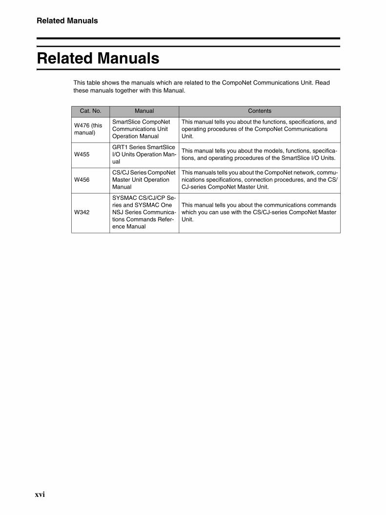
Related Manuals This table shows the manuals which are related to the CompoNet Communications Unit. Read these manuals together with this Manual.
Cat. No. Manual Contents
W476 (this manual)
SmartSlice CompoNet Communications Unit Operation Manual
This manual tells you about the functions, specifications, and operating procedures of the CompoNet Communications Unit.
W455 GRT1 Series SmartSlice I/O Units Operation Man-ual
This manual tells you about the models, functions, specifica-tions, and operating procedures of the SmartSlice I/O Units.
W456 CS/CJ Series CompoNet Master Unit Operation Manual
This manuals tells you about the CompoNet network, commu-nications specifications, connection procedures, and the CS/CJ-series CompoNet Master Unit.
W342
SYSMAC CS/CJ/CP Se-ries and SYSMAC One NSJ Series Communica-tions Commands Refer-ence Manual
This manual tells you about the communications commands which you can use with the CS/CJ-series CompoNet Master Unit.
About this Manual
About this Manual
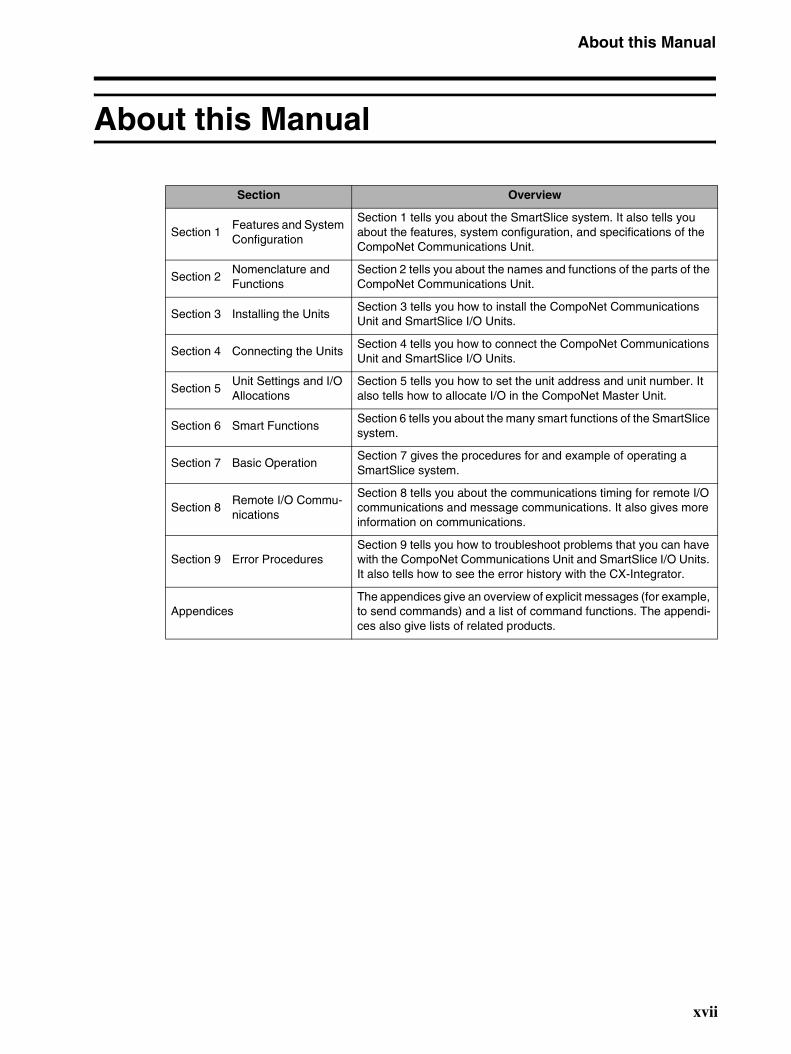
Section Overview
Section 1Features and System Configuration
Section 1 tells you about the SmartSlice system. It also tells you about the features, system configuration, and specifications of the CompoNet Communications Unit.
Section 2Nomenclature and Functions
Section 2 tells you about the names and functions of the parts of the CompoNet Communications Unit.
Section 3 Installing the UnitsSection 3 tells you how to install the CompoNet Communications Unit and SmartSlice I/O Units.
Section 4 Connecting the Units Section 4 tells you how to connect the CompoNet Communications Unit and SmartSlice I/O Units.
Section 5Unit Settings and I/O Allocations
Section 5 tells you how to set the unit address and unit number. It also tells how to allocate I/O in the CompoNet Master Unit.
Section 6 Smart Functions Section 6 tells you about the many smart functions of the SmartSlice system.
Section 7 Basic Operation Section 7 gives the procedures for and example of operating a SmartSlice system.
Section 8Remote I/O Commu-nications
Section 8 tells you about the communications timing for remote I/O communications and message communications. It also gives more information on communications.
Section 9 Error Procedures Section 9 tells you how to troubleshoot problems that you can have with the CompoNet Communications Unit and SmartSlice I/O Units. It also tells how to see the error history with the CX-Integrator.
AppendicesThe appendices give an overview of explicit messages (for example, to send commands) and a list of command functions. The appendi-ces also give lists of related products.
xvii

About this Manual
xviii
TABLE OF CONTENTS
SECTION 1Features and System Configuration . . . . . . . . . . . . . . . . . . . 1
1-1 The SmartSlice I/O System . . . . . . . . . . . . . . . . . . . . . . . . . . . . . . . . . . . . . . . . . . . . . . . . . . 2
1-2 Features of the CompoNet SmartSlice I/O Terminals . . . . . . . . . . . . . . . . . . . . . . . . . . . . . . 3
1-3 System Configuration . . . . . . . . . . . . . . . . . . . . . . . . . . . . . . . . . . . . . . . . . . . . . . . . . . . . . . 5
1-4 Specifications. . . . . . . . . . . . . . . . . . . . . . . . . . . . . . . . . . . . . . . . . . . . . . . . . . . . . . . . . . . . . 7
SECTION 2Nomenclature and Functions . . . . . . . . . . . . . . . . . . . . . . . . . 11
2-1 Nomenclature. . . . . . . . . . . . . . . . . . . . . . . . . . . . . . . . . . . . . . . . . . . . . . . . . . . . . . . . . . . . . 12
2-2 Indicators . . . . . . . . . . . . . . . . . . . . . . . . . . . . . . . . . . . . . . . . . . . . . . . . . . . . . . . . . . . . . . . . 14
2-3 Switches. . . . . . . . . . . . . . . . . . . . . . . . . . . . . . . . . . . . . . . . . . . . . . . . . . . . . . . . . . . . . . . . . 18
SECTION 3Installing the Units . . . . . . . . . . . . . . . . . . . . . . . . . . . . . . . . . 21
3-1 Installing a SmartSlice I/O Terminal . . . . . . . . . . . . . . . . . . . . . . . . . . . . . . . . . . . . . . . . . . . 22
3-2 Installing the Turnback Units . . . . . . . . . . . . . . . . . . . . . . . . . . . . . . . . . . . . . . . . . . . . . . . . 27
SECTION 4Connecting the Units . . . . . . . . . . . . . . . . . . . . . . . . . . . . . . . 29
4-1 Connecting the Communications Cables. . . . . . . . . . . . . . . . . . . . . . . . . . . . . . . . . . . . . . . . 30
4-2 Connecting the Power Supply Cables . . . . . . . . . . . . . . . . . . . . . . . . . . . . . . . . . . . . . . . . . . 31
4-3 Connecting the Turnback Cables . . . . . . . . . . . . . . . . . . . . . . . . . . . . . . . . . . . . . . . . . . . . . . 35
4-4 Precautions When Connecting the Power Supplies. . . . . . . . . . . . . . . . . . . . . . . . . . . . . . . . 36
4-5 Connecting the Signal Lines for External Devices . . . . . . . . . . . . . . . . . . . . . . . . . . . . . . . . 38
SECTION 5Unit Settings and I/O Allocations . . . . . . . . . . . . . . . . . . . . . 39
5-1 Setting the Node Addresses . . . . . . . . . . . . . . . . . . . . . . . . . . . . . . . . . . . . . . . . . . . . . . . . . . 40
5-2 Unit Numbers for SmartSlice I/O Units . . . . . . . . . . . . . . . . . . . . . . . . . . . . . . . . . . . . . . . . 41
5-3 I/O Allocations to CompoNet Master Unit . . . . . . . . . . . . . . . . . . . . . . . . . . . . . . . . . . . . . . 42
SECTION 6Smart Functions . . . . . . . . . . . . . . . . . . . . . . . . . . . . . . . . . . . 53
6-1 Overview of Smart Functions . . . . . . . . . . . . . . . . . . . . . . . . . . . . . . . . . . . . . . . . . . . . . . . . 54
6-2 Registration Table . . . . . . . . . . . . . . . . . . . . . . . . . . . . . . . . . . . . . . . . . . . . . . . . . . . . . . . . . 54
6-3 Backup Function . . . . . . . . . . . . . . . . . . . . . . . . . . . . . . . . . . . . . . . . . . . . . . . . . . . . . . . . . . 57
6-4 Automatic Restore Function . . . . . . . . . . . . . . . . . . . . . . . . . . . . . . . . . . . . . . . . . . . . . . . . . 58
6-5 Replacing Units Online . . . . . . . . . . . . . . . . . . . . . . . . . . . . . . . . . . . . . . . . . . . . . . . . . . . . . 59
6-6 Automatic Baud Rate Recognition . . . . . . . . . . . . . . . . . . . . . . . . . . . . . . . . . . . . . . . . . . . . 59
6-7 Software Setting of I/O Allocations . . . . . . . . . . . . . . . . . . . . . . . . . . . . . . . . . . . . . . . . . . . 60
xix
TABLE OF CONTENTS
6-8 Unit Conduction Time Monitor . . . . . . . . . . . . . . . . . . . . . . . . . . . . . . . . . . . . . . . . . . . . . . . 716-9 Unit Comments . . . . . . . . . . . . . . . . . . . . . . . . . . . . . . . . . . . . . . . . . . . . . . . . . . . . . . . . . . . 73
6-10 Network Communications Error History Monitor . . . . . . . . . . . . . . . . . . . . . . . . . . . . . . . . 75
6-11 I/O Communications Error History Monitor . . . . . . . . . . . . . . . . . . . . . . . . . . . . . . . . . . . . . 76
6-12 Last Maintenance Date . . . . . . . . . . . . . . . . . . . . . . . . . . . . . . . . . . . . . . . . . . . . . . . . . . . . . 77
SECTION 7Basic Operation. . . . . . . . . . . . . . . . . . . . . . . . . . . . . . . . . . . . 81
7-1 Setting Example and Basic Procedures . . . . . . . . . . . . . . . . . . . . . . . . . . . . . . . . . . . . . . . . . 82
7-2 Preparing for Work . . . . . . . . . . . . . . . . . . . . . . . . . . . . . . . . . . . . . . . . . . . . . . . . . . . . . . . . 84
7-3 Hardware Connections and Settings . . . . . . . . . . . . . . . . . . . . . . . . . . . . . . . . . . . . . . . . . . . 85
7-4 Starting Communications . . . . . . . . . . . . . . . . . . . . . . . . . . . . . . . . . . . . . . . . . . . . . . . . . . . 87
7-5 Making Sure That Operation Is Correct . . . . . . . . . . . . . . . . . . . . . . . . . . . . . . . . . . . . . . . . 88
SECTION 8Remote I/O Communications . . . . . . . . . . . . . . . . . . . . . . . . 89
8-1 Performance of Remote I/O Communications . . . . . . . . . . . . . . . . . . . . . . . . . . . . . . . . . . . 90
8-2 Performance of Message Communications . . . . . . . . . . . . . . . . . . . . . . . . . . . . . . . . . . . . . . 93
SECTION 9Error Procedures . . . . . . . . . . . . . . . . . . . . . . . . . . . . . . . . . . 95
9-1 Error Procedures with Indicators . . . . . . . . . . . . . . . . . . . . . . . . . . . . . . . . . . . . . . . . . . . . . . 96
9-2 Error Procedures with CX-Integrator . . . . . . . . . . . . . . . . . . . . . . . . . . . . . . . . . . . . . . . . . . 100
9-3 Other Error Causes and Error Procedures . . . . . . . . . . . . . . . . . . . . . . . . . . . . . . . . . . . . . . . 105
AppendicesA CompoNet Explicit Messages . . . . . . . . . . . . . . . . . . . . . . . . . . . . . . . . . . . . . . . . . . . . . . . . 109
B Object Implementation . . . . . . . . . . . . . . . . . . . . . . . . . . . . . . . . . . . . . . . . . . . . . . . . . . . . . 117
C Standard Models . . . . . . . . . . . . . . . . . . . . . . . . . . . . . . . . . . . . . . . . . . . . . . . . . . . . . . . . . . 119
D Power Consumption and Weight Tables . . . . . . . . . . . . . . . . . . . . . . . . . . . . . . . . . . . . . . . . 121
E Total I/O Current Consumption Table . . . . . . . . . . . . . . . . . . . . . . . . . . . . . . . . . . . . . . . . . 123
Index. . . . . . . . . . . . . . . . . . . . . . . . . . . . . . . . . . . . . . . . . . . . . 125
Revision History . . . . . . . . . . . . . . . . . . . . . . . . . . . . . . . . . . . 129
xx
SECTION 1Features and System Configuration
This section tells you about the SmartSlice system. It also tells you about the features, system configuration, andspecifications of the CompoNet Communications Unit.
1-1 The SmartSlice I/O System. . . . . . . . . . . . . . . . . . . . . . . . . . . . . . . . . . . . . . . 2
1-2 Features of the CompoNet SmartSlice I/O Terminals. . . . . . . . . . . . . . . . . . . 3
1-3 System Configuration . . . . . . . . . . . . . . . . . . . . . . . . . . . . . . . . . . . . . . . . . . . 5
1-4 Specifications . . . . . . . . . . . . . . . . . . . . . . . . . . . . . . . . . . . . . . . . . . . . . . . . . 7
1-4-1 Specifications of the SmartSlice System . . . . . . . . . . . . . . . . . . . . . 7
1-4-2 Specifications of the CompoNet Communications Unit . . . . . . . . . 7
1-4-3 Dimensions . . . . . . . . . . . . . . . . . . . . . . . . . . . . . . . . . . . . . . . . . . . . 9
1
The SmartSlice I/O System Section 1-1
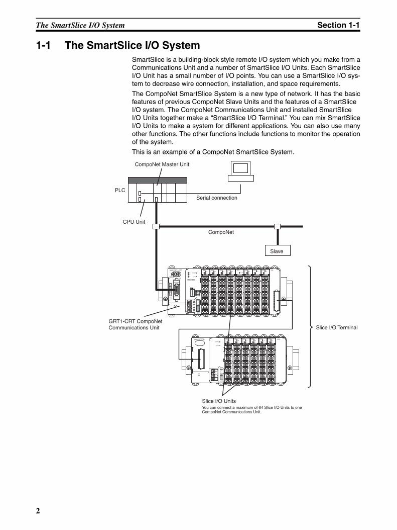
1-1 The SmartSlice I/O SystemSmartSlice is a building-block style remote I/O system which you make from aCommunications Unit and a number of SmartSlice I/O Units. Each SmartSliceI/O Unit has a small number of I/O points. You can use a SmartSlice I/O sys-tem to decrease wire connection, installation, and space requirements.
The CompoNet SmartSlice System is a new type of network. It has the basicfeatures of previous CompoNet Slave Units and the features of a SmartSlice I/O system. The CompoNet Communications Unit and installed SmartSlice I/O Units together make a “SmartSlice I/O Terminal.” You can mix SmartSliceI/O Units to make a system for different applications. You can also use manyother functions. The other functions include functions to monitor the operationof the system.
This is an example of a CompoNet SmartSlice System.
UNIT PWR
I/O PWR
UNIT
I/O
V
V
DC24VINPUT
V
V
ENDOD4TS
0 12 3
ID4TS
0 12 3
ID4TS
0 12 3
ID4TS
0 12 3
OD4TS
0 12 3
OD4TS
0 12 3
GRT1-TBL
A1
A2
A3
A4
A5
A6
A1
A2
A3
A4
A5
A6
A1
A2
A3
A4
A5
A6
A1
A2
A3
A4
A5
A6
A1
A2
A3
A4
A5
A6
A1
A2
A3
A4
A5
A6 B
6B
5B
4B
3B
2B
1
B6
B5
B4
B3
B2
B1
B6
B5
B4
B3
B2
B1
B6
B5
B4
B3
B2
B1
B6
B5
B4
B3
B2
B1
B6
B5
B4
B3
B2
B1
Slice I/O Terminal
CompoNet Master Unit
PLC
CPU Unit
Slice I/O UnitsYou can connect a maximum of 64 Slice I/O Units to one CompoNet Communications Unit.
GRT1-CRT CompoNet Communications Unit
Serial connection
Slave
CompoNet
TS
0 12 3
I/O PWR
TS
0 12 3
OD4 ROS2TS
01
ROS2TS
01
TBRGRT1-CRT
INX OUTX
WORDNODE ADR ×10 ×1
[0-63]
BS
|
BS
BD
HB
D L
DC24VINPUT
TS
UNIT PWR
I/O PWR
MS
NS
ON
1
2
3
4
REGS
I/O
ADR
BACK
UNIT
I/O
V
V
DC24VINPUT
V
V
ID4TS
0 12 3
OD4TS
0 12 3
ID4TS
0 12 3
OD4 PD2
A1
A2
A3
A4
A5
A6
B6
B5
B4
B3
B2
B1
B6
B5
B4
B3
B2
B1
A1
A2
A3
A4
A5
A6
A1
A2
A3
A4
A5
A6
A1
A2
A3
A4
A5
A6
A1
A2
A3
A4
A5
A6
A1
A2
A3
A4
A5
A6
A1
A2
A3
A4
A5
A6
A1
A2
A3
A4
A5
A6
B6
B5
B4
B3
B2
B1
B6
B5
B4
B3
B2
B1
B6
B5
B4
B3
B2
B1
B6
B5
B4
B3
B2
B1
B6
B5
B4
B3
B2
B1
B6
B5
B4
B3
B2
B1
2
Features of the CompoNet SmartSlice I/O Terminals Section 1-2
1-2 Features of the CompoNet SmartSlice I/O TerminalsThis section tells you the features of a CompoNet SmartSlice System.
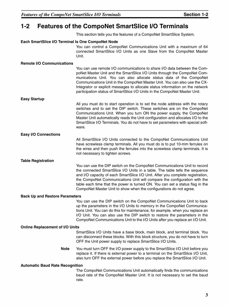
Each SmartSlice I/O Terminal Is One CompoNet Node You can control a CompoNet Communications Unit with a maximum of 64connected SmartSlice I/O Units as one Slave from the CompoNet MasterUnit.
Remote I/O Communications You can use remote I/O communications to share I/O data between the Com-poNet Master Unit and the SmartSlice I/O Units through the CompoNet Com-munications Unit. You can also allocate status data of the CompoNetCommunications Unit in the CompoNet Master Unit. You can also use the CX-Integrator or explicit messages to allocate status information on the networkparticipation status of SmartSlice I/O Units in the CompoNet Master Unit.
Easy Startup All you must do to start operation is to set the node address with the rotaryswitches and to set the DIP switch. These switches are on the CompoNetCommunications Unit. When you turn ON the power supply, the CompoNetMaster Unit automatically reads the Unit configuration and allocates I/O to theSmartSlice I/O Terminals. You do not have to set parameters with special soft-ware.
Easy I/O Connections All SmartSlice I/O Units connected to the CompoNet Communications Unithave screwless clamp terminals. All you must do is to put 10-mm ferrules onthe wires and then push the ferrules into the screwless clamp terminals. It isnot necessary to tighten screws.
Table Registration You can use the DIP switch on the CompoNet Communications Unit to recordthe connected SmartSlice I/O Units in a table. The table tells the sequenceand I/O capacity of each SmartSlice I/O Unit. After you complete registration,the CompoNet Communications Unit will compare the configuration with thetable each time that the power is turned ON. You can set a status flag in theCompoNet Master Unit to show when the configurations do not agree.
Back Up and Restore Parameters You can use the DIP switch on the CompoNet Communications Unit to backup the parameters in the I/O Units to memory in the CompoNet Communica-tions Unit. You can do this for maintenance, for example, when you replace anI/O Unit. You can also use the DIP switch to restore the parameters in theCompoNet Communications Unit to the I/O Units after you replace an I/O Unit.
Online Replacement of I/O Units SmartSlice I/O Units have a base block, main block, and terminal block. Youcan disconnect these blocks. With this block structure, you do not have to turnOFF the Unit power supply to replace SmartSlice I/O Units.
Note You must turn OFF the I/O power supply to the SmartSlice I/O Unit before youreplace it. If there is external power to a terminal on the SmartSlice I/O Unit,also turn OFF the external power before you replace the SmartSlice I/O Unit.
Automatic Baud Rate Recognition The CompoNet Communications Unit automatically finds the communicationsbaud rate of the CompoNet Master Unit. It is not necessary to set the baudrate.
3
Features of the CompoNet SmartSlice I/O Terminals Section 1-2
Software Setting of I/O Allocations You can record the node addresses and I/O configurations of Dummy Units inthe registration table to prepare for expansion of SmartSlice I/O Units. Whenyou add the I/O Units, it will not be necessary for you to set the nodeaddresses or I/O configurations. It will also not be necessary to change theladder programming very much. You can also write the ladder programmingfor the full configuration and set the Units that you will add as Dummy Units.When you change the unit configuration, it will not be necessary to change theI/O map.
Unit Conduction Time MonitorThe Unit Conduction Time Monitor records the total time that the internal cir-cuit power in DeviceNet Communications Unit is ON. You can set a thresholdin the CompoNet Communications Unit to tell the CompoNet Master Unitwhen the conduction time is longer than the threshold. You can set the thresh-old or read the conduction time with the CX-Integrator or with an explicit mes-sage.
Unit Comments You can set a comment (for example, a name or the application) for eachCompoNet Communications Unit to record the name in the CompoNet Com-munications Unit. You can use the comments to easily identify CompoNetCommunications Units when you set or monitor parameters with the CX-Inte-grator. You can set or read the comments with the CX-Integrator or with anexplicit message.
Communications Error History Monitor There is a communications error history in the CompoNet CommunicationsUnit. It records the four newest errors in communications with the CompoNetnetwork and the 64 newest errors in communications in the SmartSlice I/OTerminal. You can read the communications error status with the CX-Integra-tor or with an explicit message.
Last Maintenance Date You can record the last date on which you did maintenance in the CompoNetCommunications Unit. You can write the last maintenance date with the CX-Integrator or with an explicit message.
4
System Configuration Section 1-3
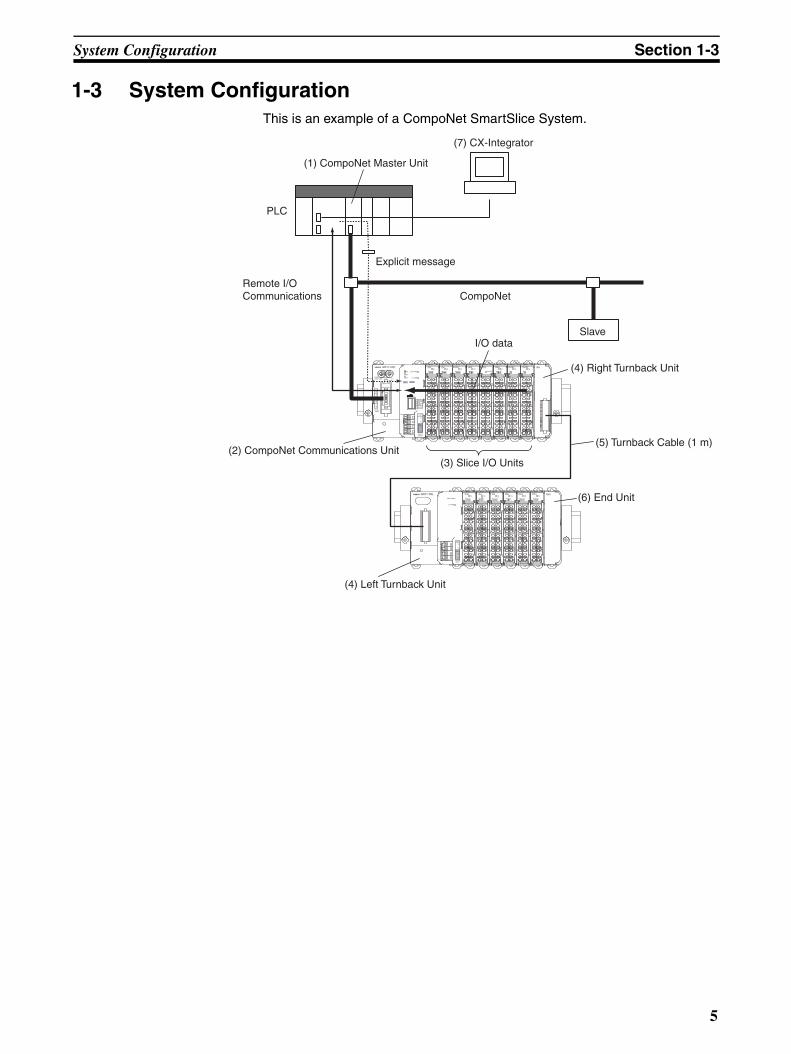
1-3 System ConfigurationThis is an example of a CompoNet SmartSlice System.
TS
0 12 3
I/O PWR
TS
0 12 3
OD4 ROS2TS
01
ROS2TS
01
TBRGRT1-CRT
INX OUTX
WORDNODE ADR ×10 ×1
(0-63)
BS
|
BS
BD
HB
D L
DC24VINPUT
TS
UNIT PWR
I/O PWR
MS
NS
ON
1
2
3
4
REGS
I/O
ADR
BACK
UNIT
I/O
V
V
DC24VINPUT
V
V
ID4TS
0 12 3
OD4TS
0 12 3
ID4TS
0 12 3
OD4 PD2
A1
A2
A3
A4
A5
A6
B6
B5
B4
B3
B2
B1
B6
B5
B4
B3
B2
B1
A1
A2
A3
A4
A5
A6
A1
A2
A3
A4
A5
A6
A1
A2
A3
A4
A5
A6
A1
A2
A3
A4
A5
A6
A1
A2
A3
A4
A5
A6
A1
A2
A3
A4
A5
A6
A1
A2
A3
A4
A5
A6
B6
B5
B4
B3
B2
B1
B6
B5
B4
B3
B2
B1
B6
B5
B4
B3
B2
B1
B6
B5
B4
B3
B2
B1
B6
B5
B4
B3
B2
B1
B6
B5
B4
B3
B2
B1
UNIT PWR
I/O PWR
UNIT
I/O
V
V
DC24VINPUT
V
V
ENDOD4TS
0 12 3
ID4TS
0 12 3
ID4TS
0 12 3
ID4TS
0 12 3
OD4TS
0 12 3
OD4TS
0 12 3
GRT1-TBL
A1
A2
A3
A4
A5
A6
A1
A2
A3
A4
A5
A6
A1
A2
A3
A4
A5
A6
A1
A2
A3
A4
A5
A6
A1
A2
A3
A4
A5
A6
A1
A2
A3
A4
A5
A6 B
6B
5B
4B
3B
2B
1
B6
B5
B4
B3
B2
B1
B6
B5
B4
B3
B2
B1
B6
B5
B4
B3
B2
B1
B6
B5
B4
B3
B2
B1
B6
B5
B4
B3
B2
B1
CompoNet
(7) CX-Integrator
Remote I/O Communications
Slave
Explicit message
PLC
(1) CompoNet Master Unit
I/O data
(2) CompoNet Communications Unit(3) Slice I/O Units
(4) Right Turnback Unit
(4) Left Turnback Unit
(5) Turnback Cable (1 m)
(6) End Unit
5
System Configuration Section 1-3
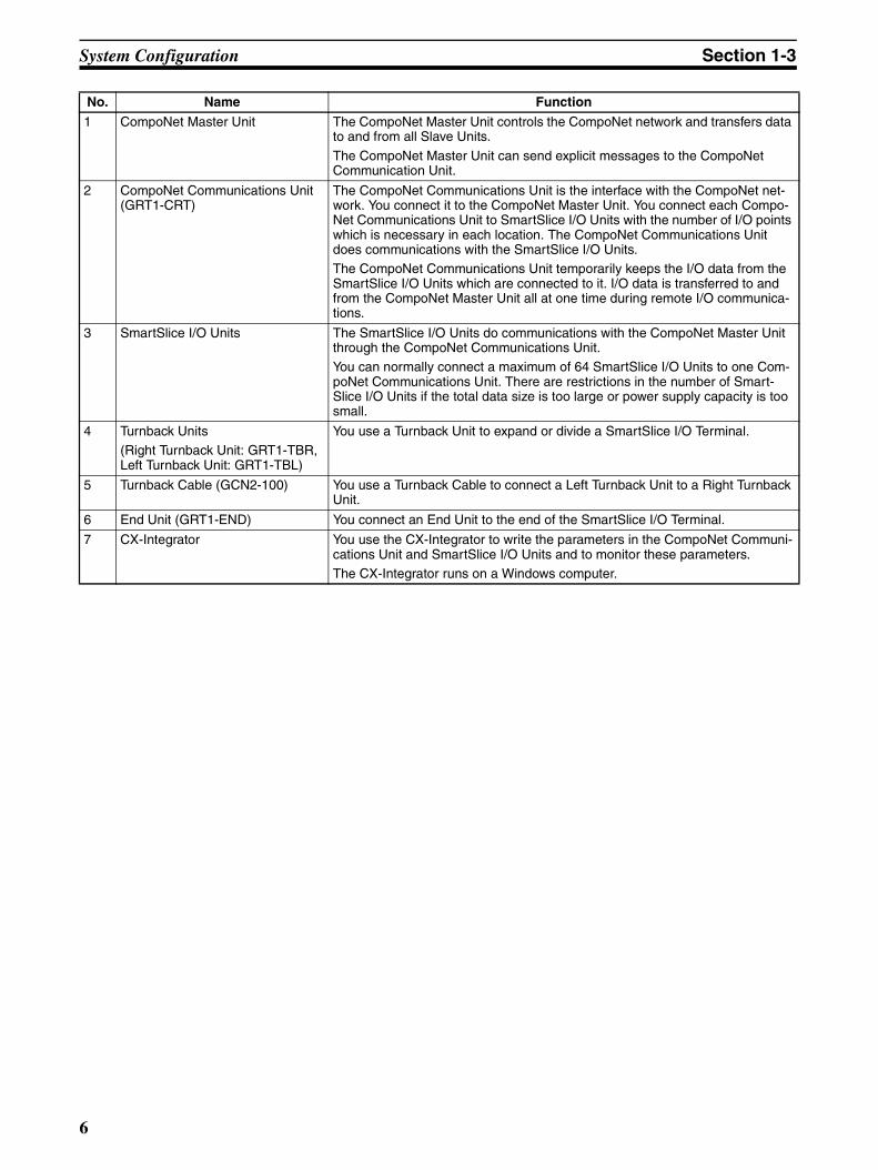
No. Name Function
1 CompoNet Master Unit The CompoNet Master Unit controls the CompoNet network and transfers data to and from all Slave Units.
The CompoNet Master Unit can send explicit messages to the CompoNet Communication Unit.
2 CompoNet Communications Unit (GRT1-CRT)
The CompoNet Communications Unit is the interface with the CompoNet net-work. You connect it to the CompoNet Master Unit. You connect each Compo-Net Communications Unit to SmartSlice I/O Units with the number of I/O points which is necessary in each location. The CompoNet Communications Unit does communications with the SmartSlice I/O Units. The CompoNet Communications Unit temporarily keeps the I/O data from the SmartSlice I/O Units which are connected to it. I/O data is transferred to and from the CompoNet Master Unit all at one time during remote I/O communica-tions.
3 SmartSlice I/O Units The SmartSlice I/O Units do communications with the CompoNet Master Unit through the CompoNet Communications Unit. You can normally connect a maximum of 64 SmartSlice I/O Units to one Com-poNet Communications Unit. There are restrictions in the number of Smart-Slice I/O Units if the total data size is too large or power supply capacity is too small.
4 Turnback Units (Right Turnback Unit: GRT1-TBR, Left Turnback Unit: GRT1-TBL)
You use a Turnback Unit to expand or divide a SmartSlice I/O Terminal.
5 Turnback Cable (GCN2-100) You use a Turnback Cable to connect a Left Turnback Unit to a Right Turnback Unit.
6 End Unit (GRT1-END) You connect an End Unit to the end of the SmartSlice I/O Terminal.
7 CX-Integrator You use the CX-Integrator to write the parameters in the CompoNet Communi-cations Unit and SmartSlice I/O Units and to monitor these parameters. The CX-Integrator runs on a Windows computer.
6
Specifications Section 1-4
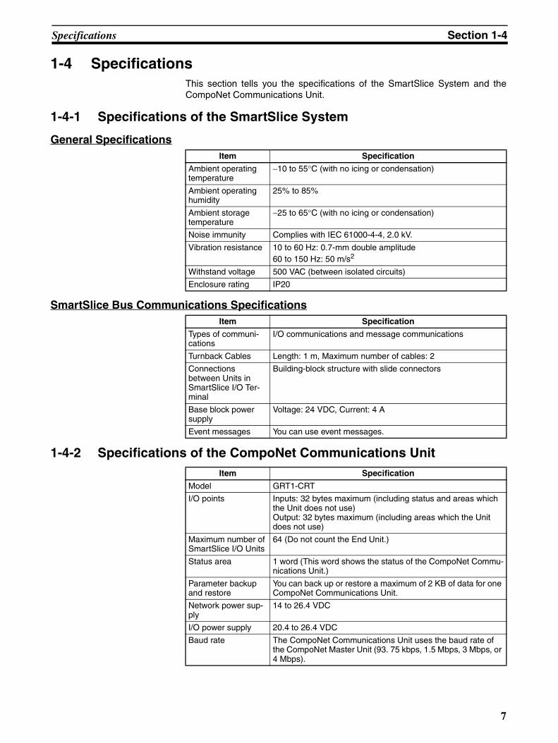
1-4 SpecificationsThis section tells you the specifications of the SmartSlice System and theCompoNet Communications Unit.
1-4-1 Specifications of the SmartSlice System
General Specifications
SmartSlice Bus Communications Specifications
1-4-2 Specifications of the CompoNet Communications Unit
Item Specification
Ambient operating temperature
−10 to 55°C (with no icing or condensation)
Ambient operating humidity
25% to 85%
Ambient storage temperature
−25 to 65°C (with no icing or condensation)
Noise immunity Complies with IEC 61000-4-4, 2.0 kV.
Vibration resistance 10 to 60 Hz: 0.7-mm double amplitude60 to 150 Hz: 50 m/s2
Withstand voltage 500 VAC (between isolated circuits)
Enclosure rating IP20
Item Specification
Types of communi-cations
I/O communications and message communications
Turnback Cables Length: 1 m, Maximum number of cables: 2
Connections between Units in SmartSlice I/O Ter-minal
Building-block structure with slide connectors
Base block power supply
Voltage: 24 VDC, Current: 4 A
Event messages You can use event messages.
Item Specification
Model GRT1-CRT
I/O points Inputs: 32 bytes maximum (including status and areas which the Unit does not use)Output: 32 bytes maximum (including areas which the Unit does not use)
Maximum number of SmartSlice I/O Units
64 (Do not count the End Unit.)
Status area 1 word (This word shows the status of the CompoNet Commu-nications Unit.)
Parameter backup and restore
You can back up or restore a maximum of 2 KB of data for one CompoNet Communications Unit.
Network power sup-ply
14 to 26.4 VDC
I/O power supply 20.4 to 26.4 VDC
Baud rate The CompoNet Communications Unit uses the baud rate of the CompoNet Master Unit (93. 75 kbps, 1.5 Mbps, 3 Mbps, or 4 Mbps).
7
Specifications Section 1-4
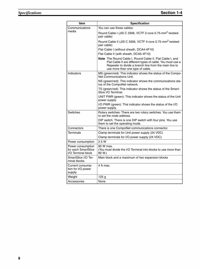
Communications media
You can use these cables:
Round Cable I (JIS C 3306, VCTF 2-core 0.75-mm2 twisted-pair cable)
Round Cable II (JIS C 3306, VCTF 4-core 0.75-mm2 twisted-pair cable)
Flat Cable I (without sheath, DCA4-4F10)Flat Cable II (with sheath, DCA5-4F10)
Note The Round Cable I, Round Cable II, Flat Cable I, and Flat Cable II are different types of cable. You must use a Repeater to divide a branch line from the main line to use more than one type of cable.
Indicators MS (green/red): This indicator shows the status of the Compo-Net Communications Unit. NS (green/red): This indicator shows the communications sta-tus of the CompoNet network.
TS (green/red): This indicator shows the status of the Smart-Slice I/O Terminal. UNIT PWR (green): This indicator shows the status of the Unit power supply. I/O PWR (green): This indicator shows the status of the I/O power supply.
Switches Rotary switches: There are two rotary switches. You use them to set the node address. DIP switch: There is one DIP switch with four pins. You use them to set the operating mode.
Connectors There is one CompoNet communications connector.
Terminals Clamp terminals for Unit power supply (24 VDC) Clamp terminals for I/O power supply (24 VDC)
Power consumption 2.5 W
Power consumption for each SmartSlice I/O Terminal block
80 W max. (You must divide the I/O Terminal into blocks to use more than 80 W.)
SmartSlice I/O Ter-minal blocks
Main block and a maximum of two expansion blocks
Current consump-tion for I/O power supply
4 A max.
Weight 125 g
Accessories None
Item Specification
8
Specifications Section 1-4
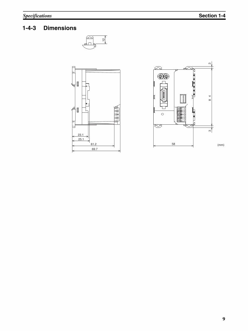
1-4-3 Dimensions
12
23.1
25.1
61.2
69.7
58
38
43
(mm)
9

Specifications Section 1-4
10
SECTION 2Nomenclature and Functions
This section tells you about the names and functions of the parts of the CompoNet Communications Unit.
2-1 Nomenclature . . . . . . . . . . . . . . . . . . . . . . . . . . . . . . . . . . . . . . . . . . . . . . . . . 12
2-1-1 CompoNet Communications Unit . . . . . . . . . . . . . . . . . . . . . . . . . . 12
2-1-2 SmartSlice I/O Units. . . . . . . . . . . . . . . . . . . . . . . . . . . . . . . . . . . . . 13
2-2 Indicators. . . . . . . . . . . . . . . . . . . . . . . . . . . . . . . . . . . . . . . . . . . . . . . . . . . . . 14
2-2-1 MS Indicator . . . . . . . . . . . . . . . . . . . . . . . . . . . . . . . . . . . . . . . . . . . 14
2-2-2 NS Indicator . . . . . . . . . . . . . . . . . . . . . . . . . . . . . . . . . . . . . . . . . . . 15
2-2-3 TS Indicator . . . . . . . . . . . . . . . . . . . . . . . . . . . . . . . . . . . . . . . . . . . 16
2-2-4 UNIT PWR Indicator . . . . . . . . . . . . . . . . . . . . . . . . . . . . . . . . . . . . 17
2-2-5 I/O PWR Indicator . . . . . . . . . . . . . . . . . . . . . . . . . . . . . . . . . . . . . . 17
2-3 Switches . . . . . . . . . . . . . . . . . . . . . . . . . . . . . . . . . . . . . . . . . . . . . . . . . . . . . 18
2-3-1 Rotary Switches . . . . . . . . . . . . . . . . . . . . . . . . . . . . . . . . . . . . . . . . 18
2-3-2 DIP Switch . . . . . . . . . . . . . . . . . . . . . . . . . . . . . . . . . . . . . . . . . . . . 18
11
Nomenclature Section 2-1
2-1 NomenclatureThis section tells you about the names and functions of the parts of the Com-poNet Communications Unit.
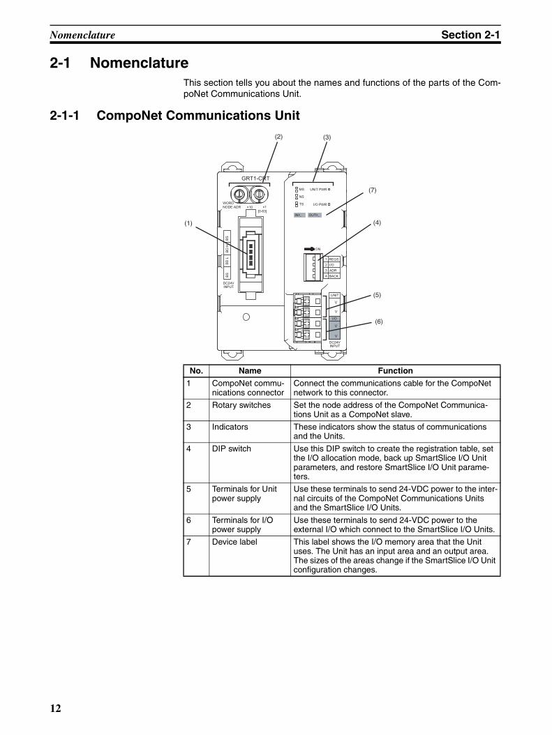
2-1-1 CompoNet Communications Unit
No. Name Function
1 CompoNet commu-nications connector
Connect the communications cable for the CompoNet network to this connector.
2 Rotary switches Set the node address of the CompoNet Communica-tions Unit as a CompoNet slave.
3 Indicators These indicators show the status of communications and the Units.
4 DIP switch Use this DIP switch to create the registration table, set the I/O allocation mode, back up SmartSlice I/O Unit parameters, and restore SmartSlice I/O Unit parame-ters.
5 Terminals for Unit power supply
Use these terminals to send 24-VDC power to the inter-nal circuits of the CompoNet Communications Units and the SmartSlice I/O Units.
6 Terminals for I/O power supply
Use these terminals to send 24-VDC power to the external I/O which connect to the SmartSlice I/O Units.
7 Device label This label shows the I/O memory area that the Unit uses. The Unit has an input area and an output area. The sizes of the areas change if the SmartSlice I/O Unit configuration changes.
(1)
(2) (3)
(4)
(5)
(6)
(7)
GRT1-CRT
INX_ OUTX_
WORDNODE ADR ×10 ×1
[0-63]
BS
B
S
BD
HB
D L
DC24VINPUT
TS
UNIT PWR
I/O PWR
MS
NS
ON
1
2
3
4
REGS
I/O
ADR
BACK
UNIT
I/O
V
V
DC24VINPUT
V
V
12
Nomenclature Section 2-1
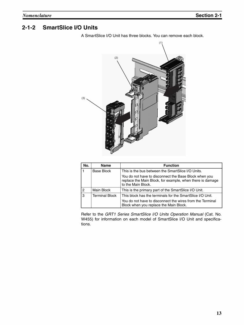
2-1-2 SmartSlice I/O Units A SmartSlice I/O Unit has three blocks. You can remove each block.
Refer to the GRT1 Series SmartSlice I/O Units Operation Manual (Cat. No.W455) for information on each model of SmartSlice I/O Unit and specifica-tions.
No. Name Function
1 Base Block This is the bus between the SmartSlice I/O Units.
You do not have to disconnect the Base Block when you replace the Main Block, for example, when there is damage to the Main Block.
2 Main Block This is the primary part of the SmartSlice I/O Unit.
3 Terminal Block This block has the terminals for the SmartSlice I/O Unit.
You do not have to disconnect the wires from the Terminal Block when you replace the Main Block.
(3)
(2)
(1)
13
Indicators Section 2-2
2-2 IndicatorsThis section tells you the specifications of the LED indicators on the frontpanel of the CompoNet Communications Unit.
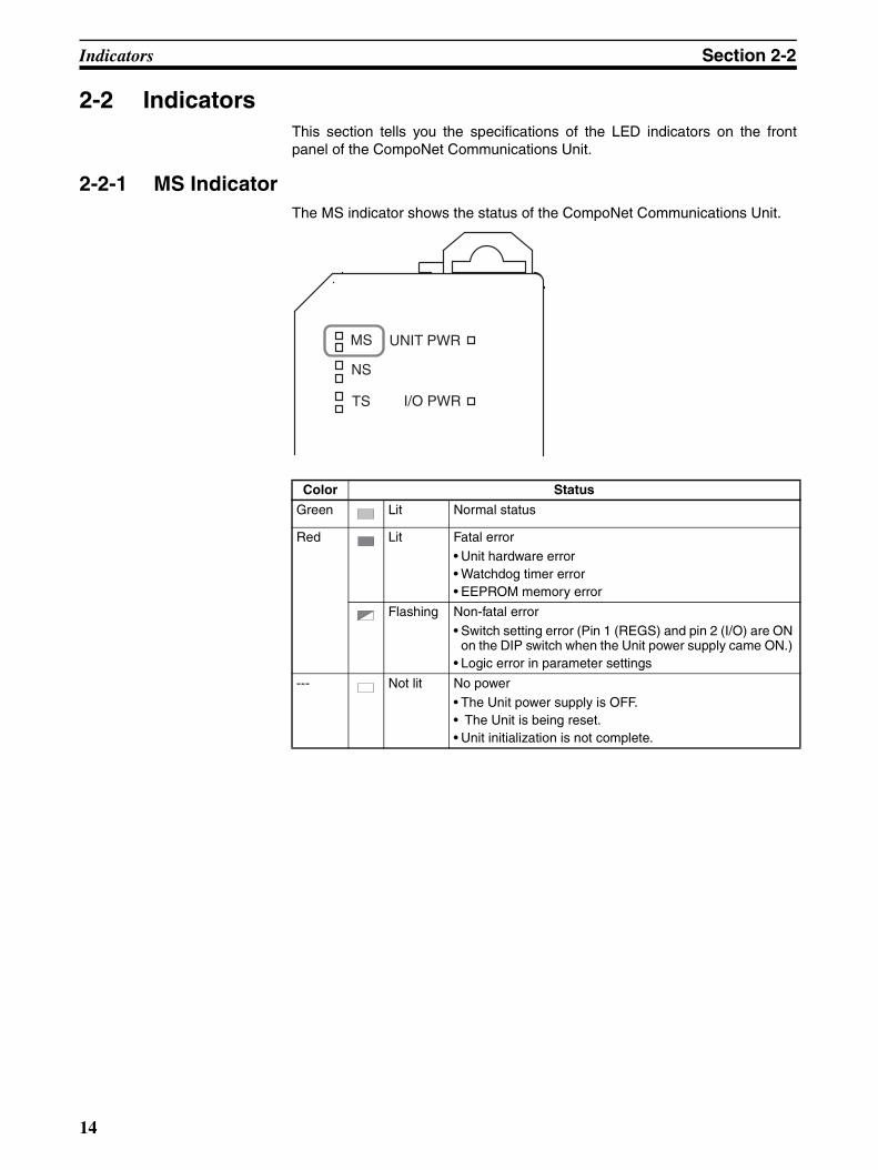
2-2-1 MS Indicator The MS indicator shows the status of the CompoNet Communications Unit.
Color Status
Green Lit Normal status
Red Lit Fatal error • Unit hardware error • Watchdog timer error • EEPROM memory error
Flashing Non-fatal error • Switch setting error (Pin 1 (REGS) and pin 2 (I/O) are ON
on the DIP switch when the Unit power supply came ON.) • Logic error in parameter settings
--- Not lit No power • The Unit power supply is OFF. • The Unit is being reset. • Unit initialization is not complete.
MS
NS
TS
UNIT PWR
I/O PWR
14
Indicators Section 2-2
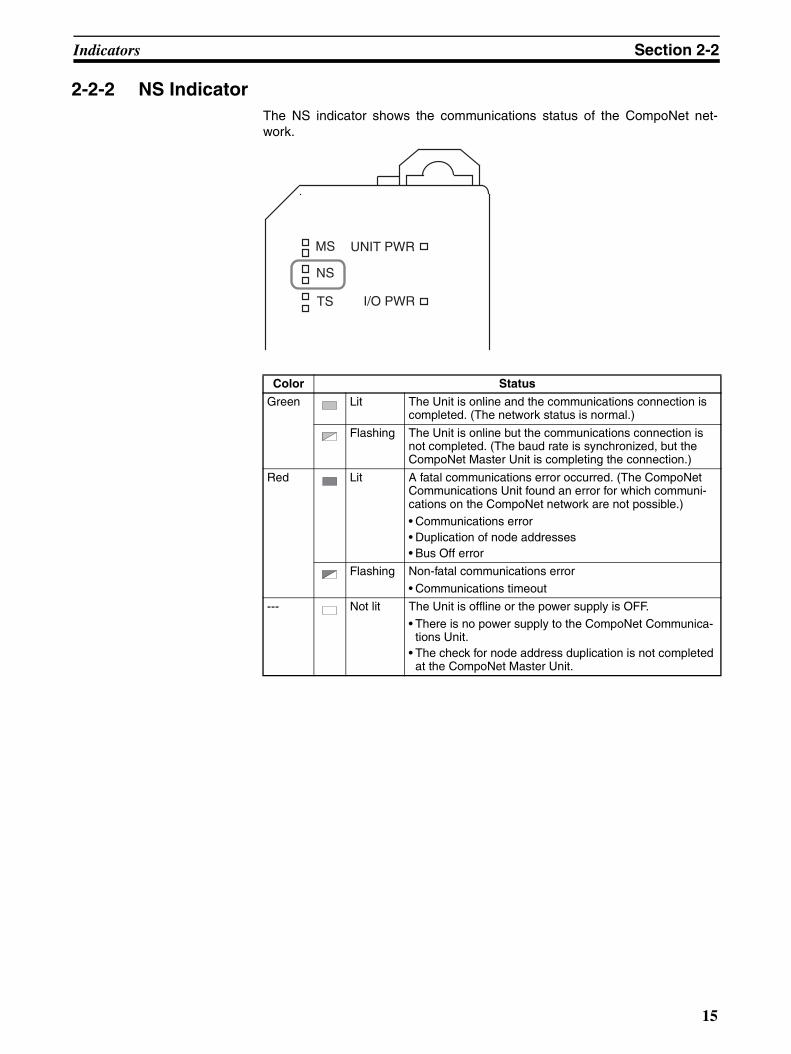
2-2-2 NS Indicator The NS indicator shows the communications status of the CompoNet net-work.
Color Status
Green Lit The Unit is online and the communications connection is completed. (The network status is normal.)
Flashing The Unit is online but the communications connection is not completed. (The baud rate is synchronized, but the CompoNet Master Unit is completing the connection.)
Red Lit A fatal communications error occurred. (The CompoNet Communications Unit found an error for which communi-cations on the CompoNet network are not possible.) • Communications error • Duplication of node addresses • Bus Off error
Flashing Non-fatal communications error
• Communications timeout
--- Not lit The Unit is offline or the power supply is OFF.
• There is no power supply to the CompoNet Communica-tions Unit.
• The check for node address duplication is not completed at the CompoNet Master Unit.
MS
NS
TS
UNIT PWR
I/O PWR
15
Indicators Section 2-2
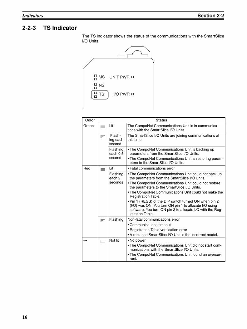
2-2-3 TS Indicator The TS indicator shows the status of the communications with the SmartSliceI/O Units.
Color Status
Green Lit The CompoNet Communications Unit is in communica-tions with the SmartSlice I/O Units.
Flash-ing each second
The SmartSlice I/O Units are joining communications at this time.
Flashing each 0.5 second
• The CompoNet Communications Unit is backing up parameters from the SmartSlice I/O Units.
• The CompoNet Communications Unit is restoring param-eters to the SmartSlice I/O Units.
Red Lit • Fatal communications error
Flashing each 2 seconds
• The CompoNet Communications Unit could not back up the parameters from the SmartSlice I/O Units.
• The CompoNet Communications Unit could not restore the parameters to the SmartSlice I/O Units.
• The CompoNet Communications Unit could not make the Registration Table.
• Pin 1 (REGS) of the DIP switch turned ON when pin 2 (I/O) was ON. You turn ON pin 1 to allocate I/O using software. You turn ON pin 2 to allocate I/O with the Reg-istration Table.
Flashing Non-fatal communications error • Communications timeout • Registration Table verification error • A replaced SmartSlice I/O Unit is the incorrect model.
--- Not lit • No power • The CompoNet Communications Unit did not start com-
munications with the SmartSlice I/O Units. • The CompoNet Communications Unit found an overcur-
rent.
MS
NS
TS
UNIT PWR
I/O PWR
16
Indicators Section 2-2
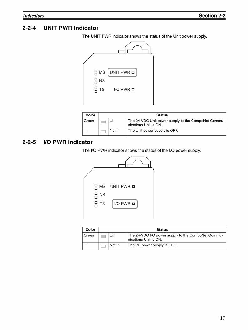
2-2-4 UNIT PWR Indicator The UNIT PWR indicator shows the status of the Unit power supply.
2-2-5 I/O PWR Indicator The I/O PWR indicator shows the status of the I/O power supply.
Color Status
Green Lit The 24-VDC Unit power supply to the CompoNet Commu-nications Unit is ON.
--- Not lit The Unit power supply is OFF.
MS
NS
TS
UNIT PWR
I/O PWR
Color Status
Green Lit The 24-VDC I/O power supply to the CompoNet Commu-nications Unit is ON.
--- Not lit The I/O power supply is OFF.
MS
NS
TS
UNIT PWR
I/O PWR
17
Switches Section 2-3
2-3 Switches This section tells you the functions of the rotary switches and the DIP switchon the front panel of the CompoNet Communications Unit.
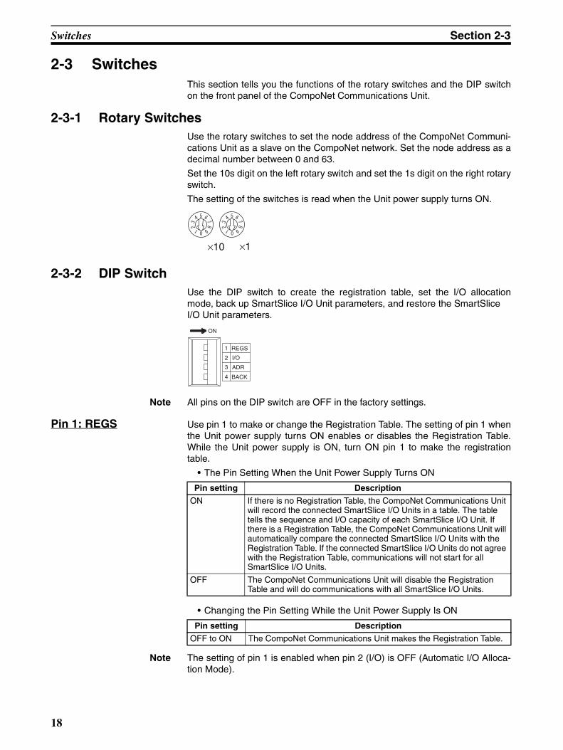
2-3-1 Rotary Switches Use the rotary switches to set the node address of the CompoNet Communi-cations Unit as a slave on the CompoNet network. Set the node address as adecimal number between 0 and 63.
Set the 10s digit on the left rotary switch and set the 1s digit on the right rotaryswitch.
The setting of the switches is read when the Unit power supply turns ON.
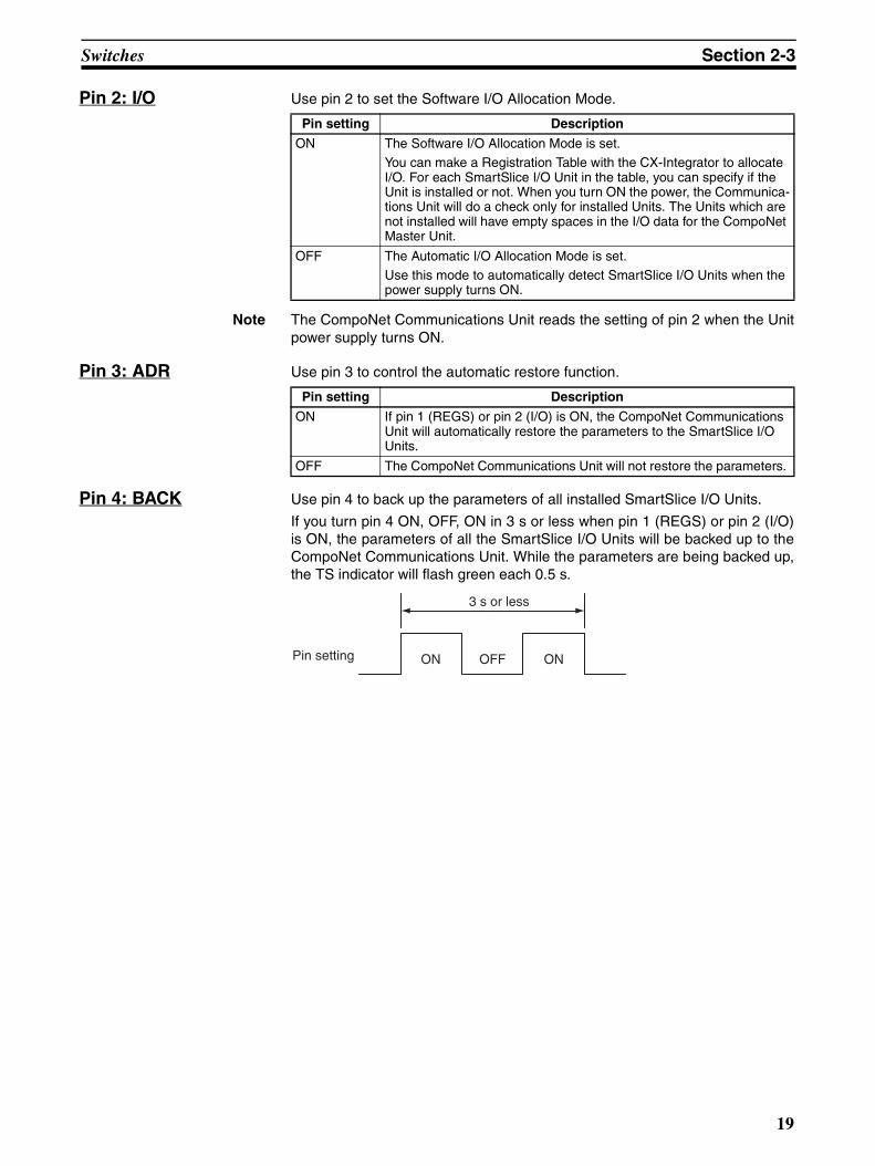
2-3-2 DIP Switch Use the DIP switch to create the registration table, set the I/O allocationmode, back up SmartSlice I/O Unit parameters, and restore the SmartSlice I/O Unit parameters.
Note All pins on the DIP switch are OFF in the factory settings.
Pin 1: REGS Use pin 1 to make or change the Registration Table. The setting of pin 1 whenthe Unit power supply turns ON enables or disables the Registration Table.While the Unit power supply is ON, turn ON pin 1 to make the registrationtable.
• The Pin Setting When the Unit Power Supply Turns ON
• Changing the Pin Setting While the Unit Power Supply Is ON
Note The setting of pin 1 is enabled when pin 2 (I/O) is OFF (Automatic I/O Alloca-tion Mode).
×10 ×1
ON
1
2
3
4
REGS
I/O
ADR
BACK
Pin setting Description
ON If there is no Registration Table, the CompoNet Communications Unit will record the connected SmartSlice I/O Units in a table. The table tells the sequence and I/O capacity of each SmartSlice I/O Unit. If there is a Registration Table, the CompoNet Communications Unit will automatically compare the connected SmartSlice I/O Units with the Registration Table. If the connected SmartSlice I/O Units do not agree with the Registration Table, communications will not start for all SmartSlice I/O Units.
OFF The CompoNet Communications Unit will disable the Registration Table and will do communications with all SmartSlice I/O Units.
Pin setting Description
OFF to ON The CompoNet Communications Unit makes the Registration Table.
18
Switches Section 2-3
Pin 2: I/O Use pin 2 to set the Software I/O Allocation Mode.
Note The CompoNet Communications Unit reads the setting of pin 2 when the Unitpower supply turns ON.
Pin 3: ADR Use pin 3 to control the automatic restore function.
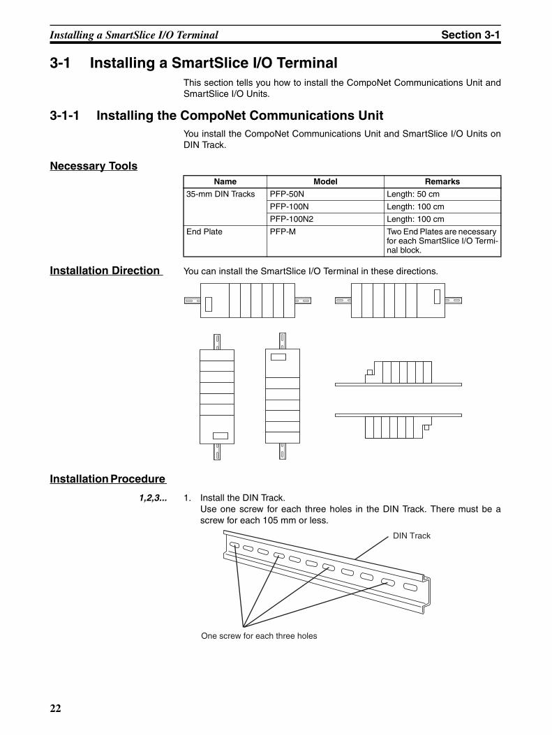
Pin 4: BACK Use pin 4 to back up the parameters of all installed SmartSlice I/O Units.
If you turn pin 4 ON, OFF, ON in 3 s or less when pin 1 (REGS) or pin 2 (I/O)is ON, the parameters of all the SmartSlice I/O Units will be backed up to theCompoNet Communications Unit. While the parameters are being backed up,the TS indicator will flash green each 0.5 s.
Pin setting Description
ON The Software I/O Allocation Mode is set. You can make a Registration Table with the CX-Integrator to allocate I/O. For each SmartSlice I/O Unit in the table, you can specify if the Unit is installed or not. When you turn ON the power, the Communica-tions Unit will do a check only for installed Units. The Units which are not installed will have empty spaces in the I/O data for the CompoNet Master Unit.
OFF The Automatic I/O Allocation Mode is set. Use this mode to automatically detect SmartSlice I/O Units when the power supply turns ON.
Pin setting Description
ON If pin 1 (REGS) or pin 2 (I/O) is ON, the CompoNet Communications Unit will automatically restore the parameters to the SmartSlice I/O Units.
OFF The CompoNet Communications Unit will not restore the parameters.
ON OFF ON
3 s or less
Pin setting
19

Switches Section 2-3
20
SECTION 3Installing the Units
This section tells you how to install the CompoNet Communications Unit and SmartSlice I/O Units.
3-1 Installing a SmartSlice I/O Terminal. . . . . . . . . . . . . . . . . . . . . . . . . . . . . . . . 22
3-1-1 Installing the CompoNet Communications Unit . . . . . . . . . . . . . . . 22
3-1-2 Installing the First SmartSlice I/O Unit . . . . . . . . . . . . . . . . . . . . . . 23
3-1-3 Installing the Other SmartSlice I/O Units. . . . . . . . . . . . . . . . . . . . . 24
3-1-4 Installing the End Unit . . . . . . . . . . . . . . . . . . . . . . . . . . . . . . . . . . . 25
3-1-5 Installing the End Plates . . . . . . . . . . . . . . . . . . . . . . . . . . . . . . . . . . 26
3-2 Installing the Turnback Units . . . . . . . . . . . . . . . . . . . . . . . . . . . . . . . . . . . . . 27
21
Installing a SmartSlice I/O Terminal Section 3-1
3-1 Installing a SmartSlice I/O TerminalThis section tells you how to install the CompoNet Communications Unit andSmartSlice I/O Units.
3-1-1 Installing the CompoNet Communications Unit You install the CompoNet Communications Unit and SmartSlice I/O Units onDIN Track.
Necessary Tools
Installation Direction You can install the SmartSlice I/O Terminal in these directions.
Installation Procedure
1,2,3... 1. Install the DIN Track. Use one screw for each three holes in the DIN Track. There must be ascrew for each 105 mm or less.
Name Model Remarks
35-mm DIN Tracks PFP-50N Length: 50 cm
PFP-100N Length: 100 cm
PFP-100N2 Length: 100 cm
End Plate PFP-M Two End Plates are necessary for each SmartSlice I/O Termi-nal block.
DIN Track
One screw for each three holes
22
Installing a SmartSlice I/O Terminal Section 3-1
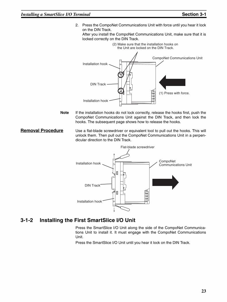
2. Press the CompoNet Communications Unit with force until you hear it lockon the DIN Track. After you install the CompoNet Communications Unit, make sure that it islocked correctly on the DIN Track.
Note If the installation hooks do not lock correctly, release the hooks first, push theCompoNet Communications Unit against the DIN Track, and then lock thehooks. The subsequent page shows how to release the hooks.
Removal Procedure Use a flat-blade screwdriver or equivalent tool to pull out the hooks. This willunlock them. Then pull out the CompoNet Communications Unit in a perpen-dicular direction to the DIN Track.
3-1-2 Installing the First SmartSlice I/O Unit Press the SmartSlice I/O Unit along the side of the CompoNet Communica-tions Unit to install it. It must engage with the CompoNet CommunicationsUnit.
Press the SmartSlice I/O Unit until you hear it lock on the DIN Track.
(1) Press with force.
(2) Make sure that the installation hooks on the Unit are locked on the DIN Track.
Installation hook
DIN Track
Installation hook
CompoNet Communications Unit
Flat-blade screwdriver
Installation hook
DIN Track
CompoNet Communications Unit
Installation hook
23
Installing a SmartSlice I/O Terminal Section 3-1
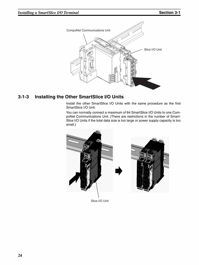
3-1-3 Installing the Other SmartSlice I/O Units Install the other SmartSlice I/O Units with the same procedure as the firstSmartSlice I/O Unit.
You can normally connect a maximum of 64 SmartSlice I/O Units to one Com-poNet Communications Unit. (There are restrictions in the number of Smart-Slice I/O Units if the total data size is too large or power supply capacity is toosmall.)
Slice I/O Unit
CompoNet Communications Unit
Slice I/O Unit
24
Installing a SmartSlice I/O Terminal Section 3-1
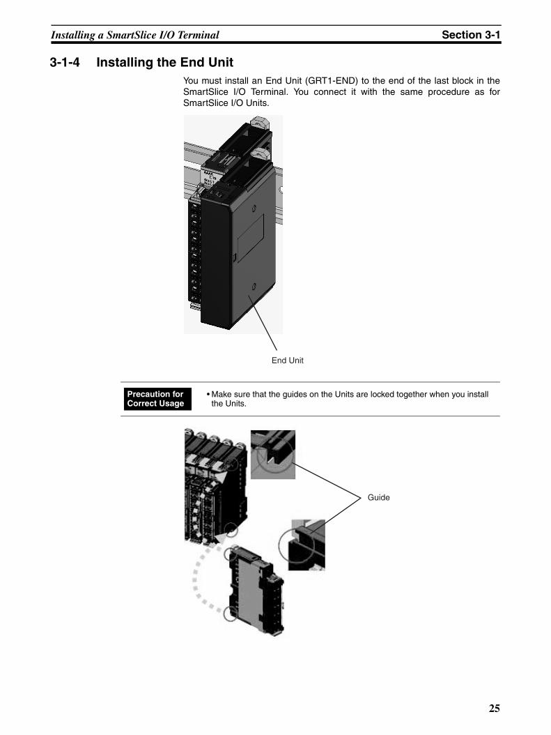
3-1-4 Installing the End Unit You must install an End Unit (GRT1-END) to the end of the last block in theSmartSlice I/O Terminal. You connect it with the same procedure as forSmartSlice I/O Units.
End Unit
• Make sure that the guides on the Units are locked together when you install the Units.
Precaution for Correct Usage
Guide
25
Installing a SmartSlice I/O Terminal Section 3-1
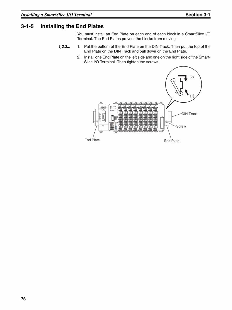
3-1-5 Installing the End Plates You must install an End Plate on each end of each block in a SmartSlice I/OTerminal. The End Plates prevent the blocks from moving.
1,2,3... 1. Put the bottom of the End Plate on the DIN Track. Then put the top of theEnd Plate on the DIN Track and pull down on the End Plate.
2. Install one End Plate on the left side and one on the right side of the Smart-Slice I/O Terminal. Then tighten the screws.
(1)
(2)
End Plate End Plate
DIN Track
Screw
TS
0 12 3
I/O PWR
TS
0 12 3
OD4 ROS2TS
01
ROS2TS
01
TBRGRT1-CRT
INX OUTX
WORDNODE ADR ×10 ×1
(0-63)
BS
|
BS
BD
HB
D L
DC24VINPUT
TS
UNIT PWR
I/O PWR
MS
NS
ON
1
2
3
4
REGS
I/O
ADR
BACK
UNIT
I/O
V
V
DC24VINPUT
V
V
ID4TS
0 12 3
OD4TS
0 12 3
ID4TS
0 12 3
OD4 PD2
A1
A2
A3
A4
A5
A6
B6
B5
B4
B3
B2
B1
B6
B5
B4
B3
B2
B1
A1
A2
A3
A4
A5
A6
A1
A2
A3
A4
A5
A6
A1
A2
A3
A4
A5
A6
A1
A2
A3
A4
A5
A6
A1
A2
A3
A4
A5
A6
A1
A2
A3
A4
A5
A6
A1
A2
A3
A4
A5
A6
B6
B5
B4
B3
B2
B1
B6
B5
B4
B3
B2
B1
B6
B5
B4
B3
B2
B1
B6
B5
B4
B3
B2
B1
B6
B5
B4
B3
B2
B1
B6
B5
B4
B3
B2
B1
26
Installing the Turnback Units Section 3-2
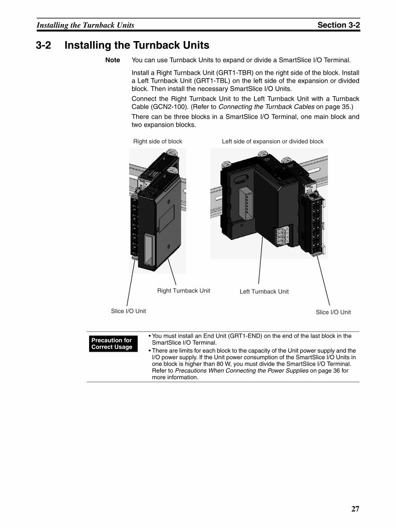
3-2 Installing the Turnback Units Note You can use Turnback Units to expand or divide a SmartSlice I/O Terminal.
Install a Right Turnback Unit (GRT1-TBR) on the right side of the block. Installa Left Turnback Unit (GRT1-TBL) on the left side of the expansion or dividedblock. Then install the necessary SmartSlice I/O Units.
Connect the Right Turnback Unit to the Left Turnback Unit with a TurnbackCable (GCN2-100). (Refer to Connecting the Turnback Cables on page 35.)
There can be three blocks in a SmartSlice I/O Terminal, one main block andtwo expansion blocks.
Right side of block Left side of expansion or divided block
Left Turnback Unit Right Turnback Unit
Slice I/O Unit Slice I/O Unit
• You must install an End Unit (GRT1-END) on the end of the last block in the SmartSlice I/O Terminal.
• There are limits for each block to the capacity of the Unit power supply and the I/O power supply. If the Unit power consumption of the SmartSlice I/O Units in one block is higher than 80 W, you must divide the SmartSlice I/O Terminal. Refer to Precautions When Connecting the Power Supplies on page 36 for more information.
Precaution for Correct Usage
27

Installing the Turnback Units Section 3-2
28
SECTION 4Connecting the Units
This section tells you how to connect the CompoNet Communications Unit and SmartSlice I/O Units.
4-1 Connecting the Communications Cables . . . . . . . . . . . . . . . . . . . . . . . . . . . . 30
4-1-1 Using Flat Cables I/II . . . . . . . . . . . . . . . . . . . . . . . . . . . . . . . . . . . . 30
4-1-2 Using Round Cables I/II . . . . . . . . . . . . . . . . . . . . . . . . . . . . . . . . . . 30
4-2 Connecting the Power Supply Cables . . . . . . . . . . . . . . . . . . . . . . . . . . . . . . . 31
4-2-1 Types of Power Supply . . . . . . . . . . . . . . . . . . . . . . . . . . . . . . . . . . . 31
4-2-2 Recommended Power Supplies . . . . . . . . . . . . . . . . . . . . . . . . . . . . 31
4-2-3 Power Supply Terminals . . . . . . . . . . . . . . . . . . . . . . . . . . . . . . . . . . 31
4-2-4 Connecting the Unit Power Supply Cables. . . . . . . . . . . . . . . . . . . . 33
4-2-5 Connecting the I/O Power Supply Cables . . . . . . . . . . . . . . . . . . . . 34
4-3 Connecting the Turnback Cables . . . . . . . . . . . . . . . . . . . . . . . . . . . . . . . . . . 35
4-4 Precautions When Connecting the Power Supplies . . . . . . . . . . . . . . . . . . . . 36
4-5 Connecting the Signal Lines for External Devices . . . . . . . . . . . . . . . . . . . . . 38
29
Connecting the Communications Cables Section 4-1
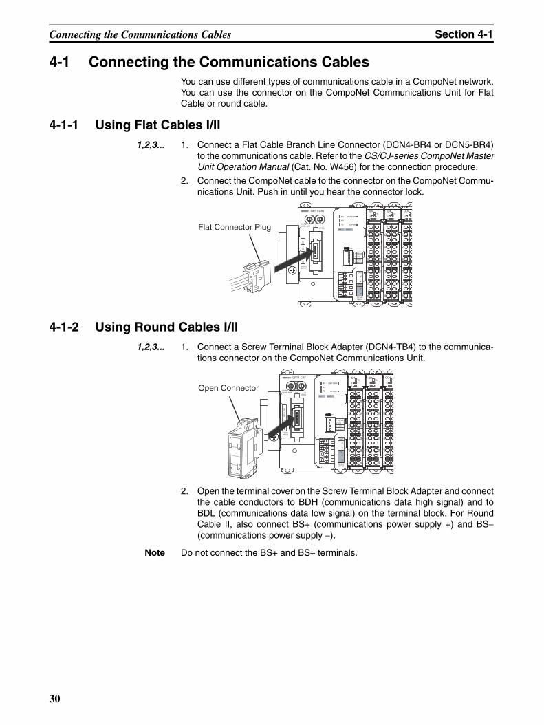
4-1 Connecting the Communications Cables You can use different types of communications cable in a CompoNet network.You can use the connector on the CompoNet Communications Unit for FlatCable or round cable.
4-1-1 Using Flat Cables I/II 1,2,3... 1. Connect a Flat Cable Branch Line Connector (DCN4-BR4 or DCN5-BR4)
to the communications cable. Refer to the CS/CJ-series CompoNet MasterUnit Operation Manual (Cat. No. W456) for the connection procedure.
2. Connect the CompoNet cable to the connector on the CompoNet Commu-nications Unit. Push in until you hear the connector lock.
4-1-2 Using Round Cables I/II 1,2,3... 1. Connect a Screw Terminal Block Adapter (DCN4-TB4) to the communica-
tions connector on the CompoNet Communications Unit.
2. Open the terminal cover on the Screw Terminal Block Adapter and connectthe cable conductors to BDH (communications data high signal) and toBDL (communications data low signal) on the terminal block. For RoundCable II, also connect BS+ (communications power supply +) and BS−(communications power supply −).
Note Do not connect the BS+ and BS− terminals.
02
Flat Connector Plug
02
GRT1-CRT
INX OUTX
WORDNODE ADR ×10 ×1
[0-63]
BS
B
S
BD
HB
D L
DC24VINPUT
TS
UNIT PWR
I/O PWR
MS
NS
ON
1
2
3
4
REGS
I/O
ADR
BACK
UNIT
I/O
V
V
DC24VINPUT
V
V
ID4TS
0 12 3
OD4TS
0 12 3
ID4TS
0 12 3
A1
A2
A3
A4
A5
A6
B6
B5
B4
B3
B2
B1
B6
B5
B4
B3
B2
B1
A1
A2
A3
A4
A5
A6
A1
A2
A3
A4
A5
A6
A1
A2
A3
A4
A5
A6
B6
B5
B4
B3
B2
B1
Open Connector
30
Connecting the Power Supply Cables Section 4-2
4-2 Connecting the Power Supply Cables You connect the power supply cables to the power supply terminals on theCompoNet Communications Unit. Network power is not necessary if you con-nect the Communications Unit to a host network.
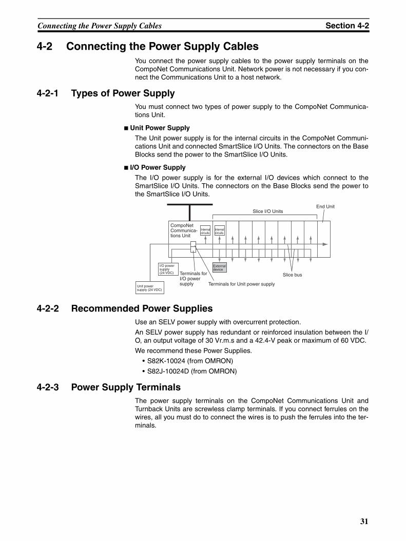
4-2-1 Types of Power Supply You must connect two types of power supply to the CompoNet Communica-tions Unit.
Unit Power Supply
The Unit power supply is for the internal circuits in the CompoNet Communi-cations Unit and connected SmartSlice I/O Units. The connectors on the BaseBlocks send the power to the SmartSlice I/O Units.
I/O Power Supply
The I/O power supply is for the external I/O devices which connect to theSmartSlice I/O Units. The connectors on the Base Blocks send the power tothe SmartSlice I/O Units.
4-2-2 Recommended Power Supplies Use an SELV power supply with overcurrent protection.
An SELV power supply has redundant or reinforced insulation between the I/O, an output voltage of 30 Vr.m.s and a 42.4-V peak or maximum of 60 VDC.
We recommend these Power Supplies.
• S82K-10024 (from OMRON)
• S82J-10024D (from OMRON)
4-2-3 Power Supply Terminals The power supply terminals on the CompoNet Communications Unit andTurnback Units are screwless clamp terminals. If you connect ferrules on thewires, all you must do to connect the wires is to push the ferrules into the ter-minals.
CompoNet Communica-tions Unit
Terminals for I/O power supply
I/O power supply (24 VDC)
Unit power supply (24 VDC)
End Unit
Internal circuits
External device
Internal circuits
Slice I/O Units
Slice bus
Terminals for Unit power supply
31
Connecting the Power Supply Cables Section 4-2
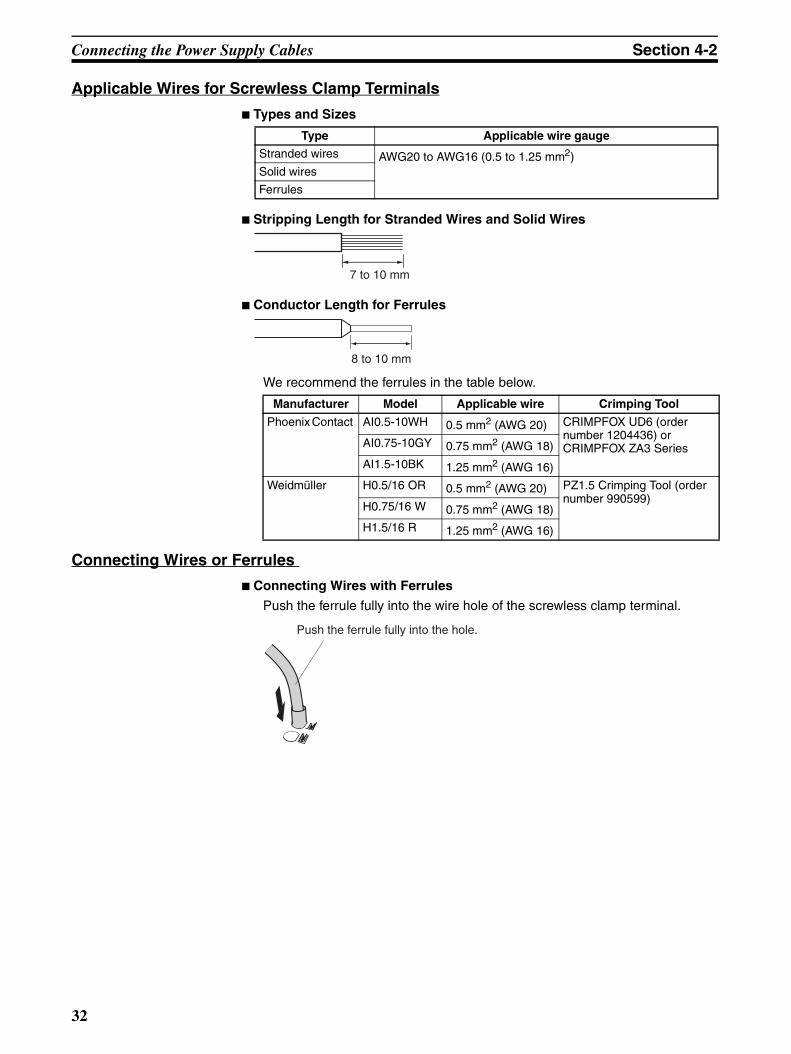
Applicable Wires for Screwless Clamp Terminals
Types and Sizes
Stripping Length for Stranded Wires and Solid Wires
Conductor Length for Ferrules
We recommend the ferrules in the table below.
Connecting Wires or Ferrules
Connecting Wires with Ferrules
Push the ferrule fully into the wire hole of the screwless clamp terminal.
Type Applicable wire gauge
Stranded wires AWG20 to AWG16 (0.5 to 1.25 mm2)Solid wires
Ferrules
7 to 10 mm
8 to 10 mm
Manufacturer Model Applicable wire Crimping Tool
Phoenix Contact AI0.5-10WH 0.5 mm2 (AWG 20) CRIMPFOX UD6 (order number 1204436) or CRIMPFOX ZA3 Series AI0.75-10GY 0.75 mm2 (AWG 18)
AI1.5-10BK 1.25 mm2 (AWG 16)
Weidmüller H0.5/16 OR 0.5 mm2 (AWG 20) PZ1.5 Crimping Tool (order number 990599)
H0.75/16 W 0.75 mm2 (AWG 18)
H1.5/16 R 1.25 mm2 (AWG 16)
Push the ferrule fully into the hole.
32
Connecting the Power Supply Cables Section 4-2
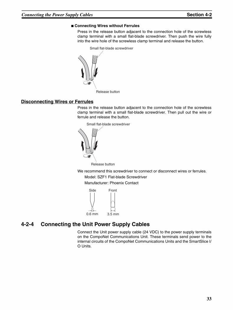
Connecting Wires without Ferrules
Press in the release button adjacent to the connection hole of the screwlessclamp terminal with a small flat-blade screwdriver. Then push the wire fullyinto the wire hole of the screwless clamp terminal and release the button.
Disconnecting Wires or FerrulesPress in the release button adjacent to the connection hole of the screwlessclamp terminal with a small flat-blade screwdriver. Then pull out the wire orferrule and release the button.
We recommend this screwdriver to connect or disconnect wires or ferrules.
Model: SZF1 Flat-blade Screwdriver
Manufacturer: Phoenix Contact
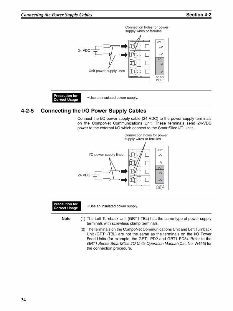
4-2-4 Connecting the Unit Power Supply Cables Connect the Unit power supply cable (24 VDC) to the power supply terminalson the CompoNet Communications Unit. These terminals send power to theinternal circuits of the CompoNet Communications Units and the SmartSlice I/O Units.
Small flat-blade screwdriver
Release button
Small flat-blade screwdriver
Release button
Side Front
0.6 mm 3.5 mm
33
Connecting the Power Supply Cables Section 4-2
4-2-5 Connecting the I/O Power Supply Cables Connect the I/O power supply cable (24 VDC) to the power supply terminalson the CompoNet Communications Unit. These terminals send 24-VDCpower to the external I/O which connect to the SmartSlice I/O Units.
Note (1) The Left Turnback Unit (GRT1-TBL) has the same type of power supplyterminals with screwless clamp terminals.
(2) The terminals on the CompoNet Communications Unit and Left TurnbackUnit (GRT1-TBL) are not the same as the terminals on the I/O PowerFeed Units (for example, the GRT1-PD2 and GRT1-PD8). Refer to theGRT1 Series SmartSlice I/O Units Operation Manual (Cat. No. W455) forthe connection procedure.
24 VDC
UNIT
I/O
DC24VINPUT
Connection holes for power supply wires or ferrules
Unit power supply lines
+V
−V
+V
−V
• Use an insulated power supply. Precaution for Correct Usage
24 VDC
UNIT
I/O
DC24VINPUT
+V
−V
+V
−V
Connection holes for power supply wires or ferrules
I/O power supply lines
• Use an insulated power supply. Precaution for Correct Usage
34
Connecting the Turnback Cables Section 4-3
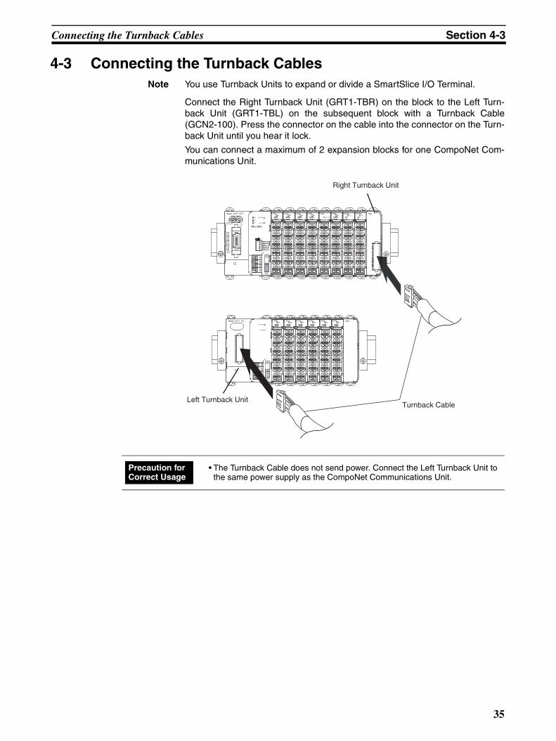
4-3 Connecting the Turnback Cables Note You use Turnback Units to expand or divide a SmartSlice I/O Terminal.
Connect the Right Turnback Unit (GRT1-TBR) on the block to the Left Turn-back Unit (GRT1-TBL) on the subsequent block with a Turnback Cable(GCN2-100). Press the connector on the cable into the connector on the Turn-back Unit until you hear it lock.
You can connect a maximum of 2 expansion blocks for one CompoNet Com-munications Unit.
UNIT PWR
I/O PWR
UNIT
I/O
V
V
DC24VINPUT
V
V
ENDOD4TS
0 12 3
ID4TS
0 12 3
ID4TS
0 12 3
ID4TS
0 12 3
OD4TS
0 12 3
OD4TS
0 12 3
GRT1-TBL
A1
A2
A3
A4
A5
A6
A1
A2
A3
A4
A5
A6
A1
A2
A3
A4
A5
A6
A1
A2
A3
A4
A5
A6
A1
A2
A3
A4
A5
A6
A1
A2
A3
A4
A5
A6 B
6B
5B
4B
3B
2B
1
B6
B5
B4
B3
B2
B1
B6
B5
B4
B3
B2
B1
B6
B5
B4
B3
B2
B1
B6
B5
B4
B3
B2
B1
B6
B5
B4
B3
B2
B1
Right Turnback Unit
Left Turnback Unit Turnback Cable
TS
0 12 3
I/O PWR
TS
0 12 3
OD4 ROS2TS
01
ROS2TS
01
TBRGRT1-CRT
INX OUTX
WORDNODE ADR ×10 ×1
[0-63]
B
S |
BS
BD
HB
D L
DC24VINPUT
TS
UNIT PWR
I/O PWR
MS
NS
ON
1
2
3
4
REGS
I/O
ADR
BACK
UNIT
I/O
V
V
DC24VINPUT
V
V
ID4TS
0 12 3
OD4TS
0 12 3
ID4TS
0 12 3
OD4 PD2
A1
A2
A3
A4
A5
A6
B6
B5
B4
B3
B2
B1
B6
B5
B4
B3
B2
B1
A1
A2
A3
A4
A5
A6
A1
A2
A3
A4
A5
A6
A1
A2
A3
A4
A5
A6
A1
A2
A3
A4
A5
A6
A1
A2
A3
A4
A5
A6
A1
A2
A3
A4
A5
A6
A1
A2
A3
A4
A5
A6
B6
B5
B4
B3
B2
B1
B6
B5
B4
B3
B2
B1
B6
B5
B4
B3
B2
B1
B6
B5
B4
B3
B2
B1
B6
B5
B4
B3
B2
B1
B6
B5
B4
B3
B2
B1
• The Turnback Cable does not send power. Connect the Left Turnback Unit to the same power supply as the CompoNet Communications Unit.
Precaution for Correct Usage
35
Precautions When Connecting the Power Supplies Section 4-4
4-4 Precautions When Connecting the Power Supplies There are limits for each block to the capacities of the power supplies. Thetotal power consumption of the CompoNet Communications Unit and Smart-Slice I/O Units must not be larger than 80 W. The total current consumption ofthe I/O devices which connect to the SmartSlice I/O Units must not be largerthan 4 A.
If the current consumption or power consumption is too large, do the proce-dure below.
Total Unit Power Consumption
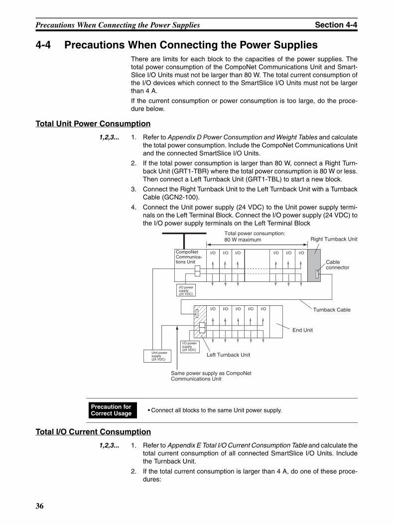
1,2,3... 1. Refer to Appendix D Power Consumption and Weight Tables and calculatethe total power consumption. Include the CompoNet Communications Unitand the connected SmartSlice I/O Units.
2. If the total power consumption is larger than 80 W, connect a Right Turn-back Unit (GRT1-TBR) where the total power consumption is 80 W or less.Then connect a Left Turnback Unit (GRT1-TBL) to start a new block.
3. Connect the Right Turnback Unit to the Left Turnback Unit with a TurnbackCable (GCN2-100).
4. Connect the Unit power supply (24 VDC) to the Unit power supply termi-nals on the Left Terminal Block. Connect the I/O power supply (24 VDC) tothe I/O power supply terminals on the Left Terminal Block
Total I/O Current Consumption
1,2,3... 1. Refer to Appendix E Total I/O Current Consumption Table and calculate thetotal current consumption of all connected SmartSlice I/O Units. Includethe Turnback Unit.
2. If the total current consumption is larger than 4 A, do one of these proce-dures:
I/O
I/O I/O I/O I/O I/O
I/O I/O I/O I/OI/O
Right Turnback Unit Total power consumption: 80 W maximum
Cable connector
CompoNet Communica-tions Unit
I/O power supply (24 VDC)
I/O power supply (24 VDC)
End Unit
Turnback Cable
Left Turnback Unit
Same power supply as CompoNet Communications Unit
Unit power supply (24 VDC)
• Connect all blocks to the same Unit power supply. Precaution for Correct Usage
36
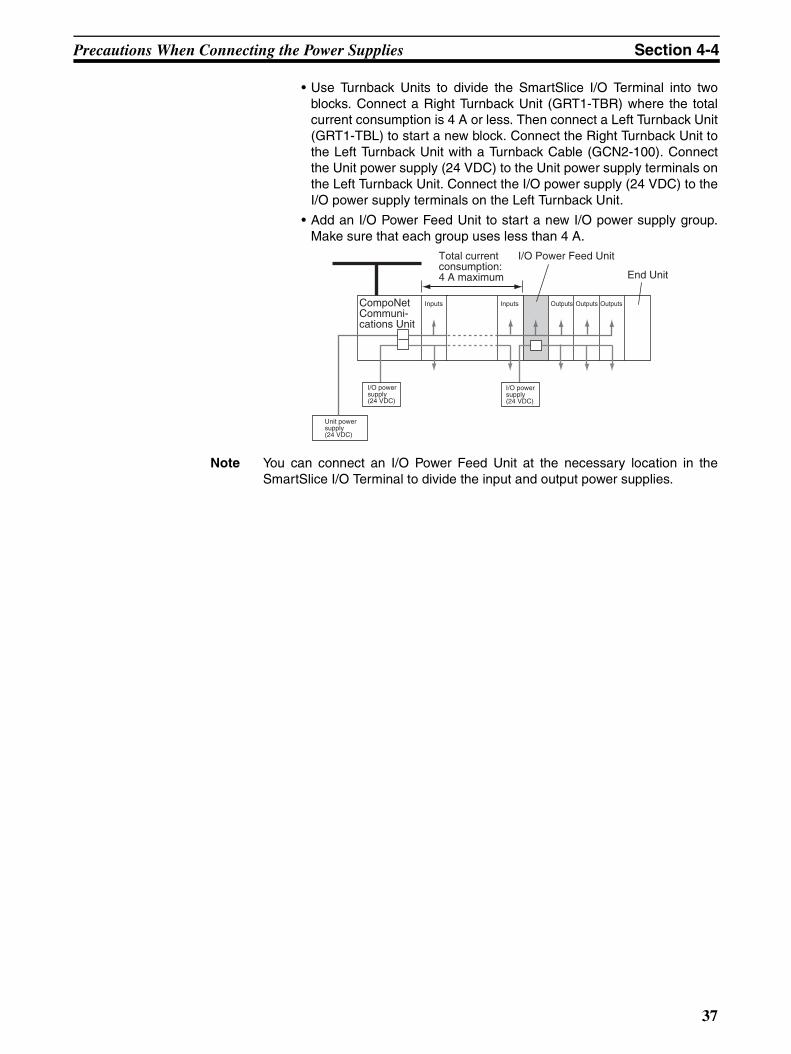
Precautions When Connecting the Power Supplies Section 4-4
• Use Turnback Units to divide the SmartSlice I/O Terminal into twoblocks. Connect a Right Turnback Unit (GRT1-TBR) where the totalcurrent consumption is 4 A or less. Then connect a Left Turnback Unit(GRT1-TBL) to start a new block. Connect the Right Turnback Unit tothe Left Turnback Unit with a Turnback Cable (GCN2-100). Connectthe Unit power supply (24 VDC) to the Unit power supply terminals onthe Left Turnback Unit. Connect the I/O power supply (24 VDC) to theI/O power supply terminals on the Left Turnback Unit.
• Add an I/O Power Feed Unit to start a new I/O power supply group.Make sure that each group uses less than 4 A.
Note You can connect an I/O Power Feed Unit at the necessary location in theSmartSlice I/O Terminal to divide the input and output power supplies.
I/O power supply (24 VDC)
I/O power supply (24 VDC)
CompoNet Communi-cations Unit
Unit power supply (24 VDC)
Inputs
End Unit
I/O Power Feed Unit Total current consumption: 4 A maximum
Inputs Outputs Outputs Outputs
37

Connecting the Signal Lines for External Devices Section 4-5
4-5 Connecting the Signal Lines for External DevicesConnect the I/O signal lines from the external devices to the I/O terminals onthe SmartSlice I/O Units. The I/O terminals on the SmartSlice I/O Units arethe same type of screwless clamp terminal as on the CompoNet Communica-tions Unit.
Refer to the GRT1 Series SmartSlice I/O Units Operation Manual (Cat. No.W455) for more information.
38
SECTION 5Unit Settings and I/O Allocations
This section tells you how to set the unit address and unit number. It also tells how to allocate I/O in the CompoNet MasterUnit.
5-1 Setting the Node Addresses . . . . . . . . . . . . . . . . . . . . . . . . . . . . . . . . . . . . . . 40
5-2 Unit Numbers for SmartSlice I/O Units . . . . . . . . . . . . . . . . . . . . . . . . . . . . . 41
5-3 I/O Allocations to CompoNet Master Unit . . . . . . . . . . . . . . . . . . . . . . . . . . . 42
5-3-1 Overview of I/O Allocations. . . . . . . . . . . . . . . . . . . . . . . . . . . . . . . 42
5-3-2 Restrictions for Data Sizes and Number of Units. . . . . . . . . . . . . . . 44
5-3-3 Status Words . . . . . . . . . . . . . . . . . . . . . . . . . . . . . . . . . . . . . . . . . . . 46
5-3-4 Allocating I/O with the CX-Integrator . . . . . . . . . . . . . . . . . . . . . . . 51
39
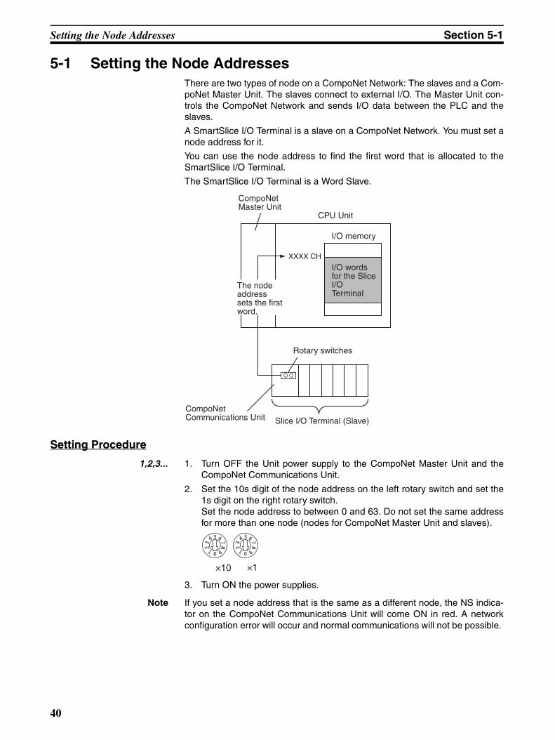
Setting the Node Addresses Section 5-1
5-1 Setting the Node Addresses There are two types of node on a CompoNet Network: The slaves and a Com-poNet Master Unit. The slaves connect to external I/O. The Master Unit con-trols the CompoNet Network and sends I/O data between the PLC and theslaves.
A SmartSlice I/O Terminal is a slave on a CompoNet Network. You must set anode address for it.
You can use the node address to find the first word that is allocated to theSmartSlice I/O Terminal.
The SmartSlice I/O Terminal is a Word Slave.
Setting Procedure
1,2,3... 1. Turn OFF the Unit power supply to the CompoNet Master Unit and theCompoNet Communications Unit.
2. Set the 10s digit of the node address on the left rotary switch and set the1s digit on the right rotary switch. Set the node address to between 0 and 63. Do not set the same addressfor more than one node (nodes for CompoNet Master Unit and slaves).
3. Turn ON the power supplies.
Note If you set a node address that is the same as a different node, the NS indica-tor on the CompoNet Communications Unit will come ON in red. A networkconfiguration error will occur and normal communications will not be possible.
XXXX CH
CompoNet Master Unit
CPU Unit
I/O memory
I/O words for the Slice I/O Terminal
The node address sets the first word.
Rotary switches
Slice I/O Terminal (Slave)
CompoNet Communications Unit
×10 ×1
40
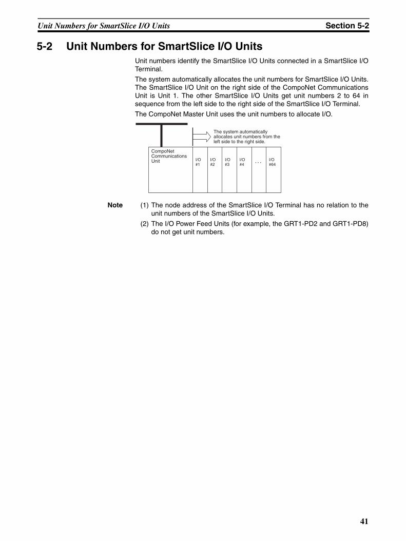
Unit Numbers for SmartSlice I/O Units Section 5-2
5-2 Unit Numbers for SmartSlice I/O Units Unit numbers identify the SmartSlice I/O Units connected in a SmartSlice I/OTerminal.
The system automatically allocates the unit numbers for SmartSlice I/O Units.The SmartSlice I/O Unit on the right side of the CompoNet CommunicationsUnit is Unit 1. The other SmartSlice I/O Units get unit numbers 2 to 64 insequence from the left side to the right side of the SmartSlice I/O Terminal.
The CompoNet Master Unit uses the unit numbers to allocate I/O.
Note (1) The node address of the SmartSlice I/O Terminal has no relation to theunit numbers of the SmartSlice I/O Units.
(2) The I/O Power Feed Units (for example, the GRT1-PD2 and GRT1-PD8)do not get unit numbers.
I/O #1
I/O #2
I/O #3
I/O #4
I/O #64
The system automatically allocates unit numbers from the left side to the right side.
CompoNet Communications Unit
41
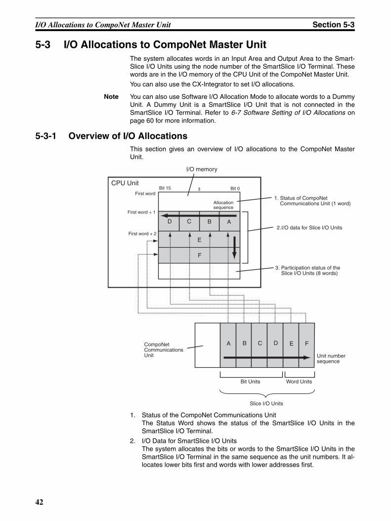
I/O Allocations to CompoNet Master Unit Section 5-3
5-3 I/O Allocations to CompoNet Master Unit The system allocates words in an Input Area and Output Area to the Smart-Slice I/O Units using the node number of the SmartSlice I/O Terminal. Thesewords are in the I/O memory of the CPU Unit of the CompoNet Master Unit.
You can also use the CX-Integrator to set I/O allocations.
Note You can also use Software I/O Allocation Mode to allocate words to a DummyUnit. A Dummy Unit is a SmartSlice I/O Unit that is not connected in theSmartSlice I/O Terminal. Refer to 6-7 Software Setting of I/O Allocations onpage 60 for more information.
5-3-1 Overview of I/O Allocations This section gives an overview of I/O allocations to the CompoNet MasterUnit.
1. Status of the CompoNet Communications UnitThe Status Word shows the status of the SmartSlice I/O Units in theSmartSlice I/O Terminal.
2. I/O Data for SmartSlice I/O Units The system allocates the bits or words to the SmartSlice I/O Units in theSmartSlice I/O Terminal in the same sequence as the unit numbers. It al-locates lower bits first and words with lower addresses first.
FE
ABCD
E
A B C D
8
F
I/O memory
CPU Unit
1. Status of CompoNet Communications Unit (1 word)
2. I/O data for Slice I/O Units
3. Participation status of the Slice I/O Units (8 words)
Bit 15 Bit 0First word
First word + 1
First word + 2
Allocation sequence
CompoNet Communications Unit Unit number
sequence
Bit Units Word Units
Slice I/O Units
42
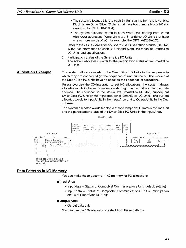
I/O Allocations to CompoNet Master Unit Section 5-3
• The system allocates 2 bits to each Bit Unit starting from the lower bits.Bit Units are SmartSlice I/O Units that have two or more bits of I/O (forexample, the GRT1-ID4/OD4).
• The system allocates words to each Word Unit starting from wordswith lower addresses. Word Units are SmartSlice I/O Units that haveone or more words of I/O (for example, the GRT1-AD2/DA2C).
Refer to the GRT1 Series SmartSlice I/O Units Operation Manual (Cat. No.W455) for information on each Bit Unit and Word Unit model of SmartSliceI/O Units and specifications.
3. Participation Status of the SmartSlice I/O Units The system allocates 8 words for the participation status of the SmartSliceI/O Units.
Allocation Example The system allocates words to the SmartSlice I/O Units in the sequence inwhich they are connected (in the sequence of unit numbers). The models ofthe SmartSlice I/O Units have no effect on the sequence of allocations.
Unless you use the CX-Integrator to set I/O allocations, the system alwaysallocates words in the same sequence starting from the first word for the nodeaddress. The sequence is the status, left SmartSlice I/O Unit, subsequentSmartSlice I/O Unit on the right side, other SmartSlice I/O Units. The systemallocates words to Input Units in the Input Area and to Output Units in the Out-put Area.
The system allocates words for status of the CompoNet Communications Unitand the participation status of the SmartSlice I/O Units in the Input Area.
Data Patterns in I/O MemoryYou can make these patterns in I/O memory for I/O allocations.
Input Area
• Input data + Status of CompoNet Communications Unit (default setting)
• Input data + Status of CompoNet Communications Unit + Participationstatus of SmartSlice I/O Units
Output Area
• Output data only
You can use the CX-Integrator to select from these patterns.
+1 #3 #2 #1
#4
#6 #5
8
+2
+3
8
Slice I/O Units
Compo-Net Com-munica-tions Unit
Unit 1ID4(4 bits)
Unit 2ID4(4 bits)
Unit 3ID4(4 bits)
Unit 4AD2(2 words)
Unit 5OD4(4 bits)
Unit 6ROS2(2 bits)
Word Bit 15
Input Area
Word Bit 15 Bit 0First word
Status of CompoNet Communications Unit
Not used.
These bits are not allocated because the subsequent Unit is a Word Unit.
Output Area
Not used.
Bit 0First word
43
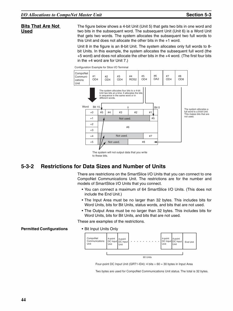
I/O Allocations to CompoNet Master Unit Section 5-3
Bits That Are Not Used
The figure below shows a 4-bit Unit (Unit 5) that gets two bits in one word andtwo bits in the subsequent word. The subsequent Unit (Unit 6) is a Word Unitthat gets two words. The system allocates the subsequent two full words tothis Unit and does not allocate the other bits in the +1 word.
Unit 8 in the figure is an 8-bit Unit. The system allocates only full words to 8-bit Units. In this example, the system allocates the subsequent full word (the+5 word) and does not allocate the other bits in the +4 word. (The first four bitsin the +4 word are for Unit 7.)
5-3-2 Restrictions for Data Sizes and Number of UnitsThere are restrictions on the SmartSlice I/O Units that you can connect to oneCompoNet Communications Unit. The restrictions are for the number andmodels of SmartSlice I/O Units that you connect.
• You can connect a maximum of 64 SmartSlice I/O Units. (This does notinclude the End Unit.)
• The Input Area must be no larger than 32 bytes. This includes bits forWord Units, bits for Bit Units, status words, and bits that are not used.
• The Output Area must be no larger than 32 bytes. This includes bits forWord Units, bits for Bit Units, and bits that are not used.
These are examples of the restrictions.
Permitted Configurations • Bit Input Units Only
8
+1
+0 #5 #4 #3 #2 #1
#5
#6+2
+3
#1OD4
#2OD4
#3OD4
#4ROS2
#5OD4
#6DA2
#7OD4
#8OD8
+4 #7
+5 #8
Configuration Example for Slice I/O Terminal
CompoNet Communi-cations Unit
The system allocates four bits to a 4-bit Unit two bits at a time. It allocates the bits in sequence in the same word or in different words.
Word Bit 15 Bit 0
Not used.
Not used.
Not used.
The system allocates a full word to a 8-bit Unit. This makes bits that are not used.
The system will not output data that you write to these bits.
CompoNet Communications Unit
4-point DC Input Unit
4-point DC Input Unit
4-point DC Input Unit
4-point DC Input Unit
End Unit
60 Units
Four-point DC Input Unit (GRT1-ID4): 4 bits × 60 = 30 bytes in Input Area
Two bytes are used for CompoNet Communications Unit status. The total is 32 bytes.
44
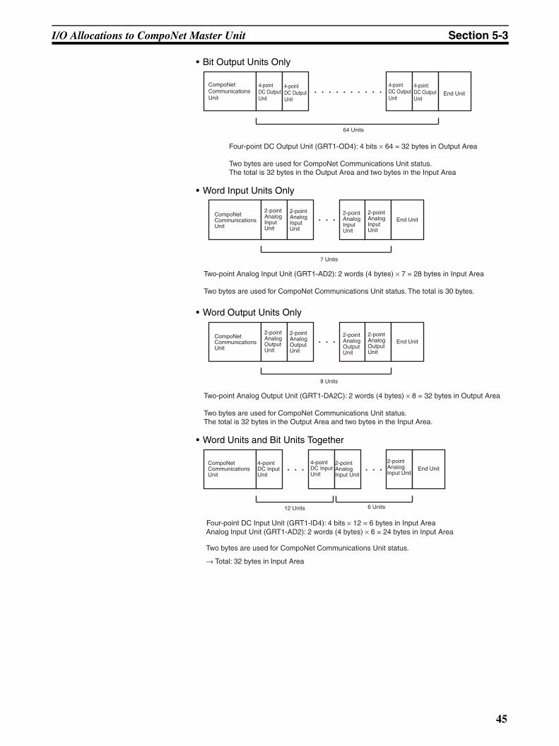
I/O Allocations to CompoNet Master Unit Section 5-3
• Bit Output Units Only
• Word Input Units Only
• Word Output Units Only
• Word Units and Bit Units Together
CompoNet Communications Unit
4-point DC Output Unit
4-point DC Output Unit
4-point DC Output Unit
4-point DC Output Unit
End Unit
64 Units
Four-point DC Output Unit (GRT1-OD4): 4 bits × 64 = 32 bytes in Output Area
Two bytes are used for CompoNet Communications Unit status. The total is 32 bytes in the Output Area and two bytes in the Input Area
CompoNet Communications Unit
2-point Analog Input Unit
2-point Analog Input Unit
2-point Analog Input Unit
2-point Analog Input Unit
End Unit
7 Units
Two-point Analog Input Unit (GRT1-AD2): 2 words (4 bytes) × 7 = 28 bytes in Input Area
Two bytes are used for CompoNet Communications Unit status. The total is 30 bytes.
CompoNet Communications Unit
2-point Analog Output Unit
2-point Analog Output Unit
2-point Analog Output Unit
2-point Analog Output Unit
End Unit
8 Units
Two-point Analog Output Unit (GRT1-DA2C): 2 words (4 bytes) × 8 = 32 bytes in Output Area
Two bytes are used for CompoNet Communications Unit status. The total is 32 bytes in the Output Area and two bytes in the Input Area.
CompoNet Communications Unit
4-point DC Input Unit
4-point DC Input Unit
2-point Analog Input Unit
2-point Analog Input Unit
End Unit
12 Units 6 Units
Analog Input Unit (GRT1-AD2): 2 words (4 bytes) × 6 = 24 bytes in Input Area
Two bytes are used for CompoNet Communications Unit status.
→ Total: 32 bytes in Input Area
Four-point DC Input Unit (GRT1-ID4): 4 bits × 12 = 6 bytes in Input Area
45
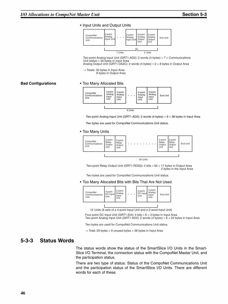
I/O Allocations to CompoNet Master Unit Section 5-3
• Input Units and Output Units
Bad Configurations • Too Many Allocated Bits
• Too Many Units
• Too Many Allocated Bits with Bits That Are Not Used
5-3-3 Status Words The status words show the status of the SmartSlice I/O Units in the Smart-Slice I/O Terminal, the connection status with the CompoNet Master Unit, andthe participation status.
There are two type of status: Status of the CompoNet Communications Unitand the participation status of the SmartSlice I/O Units. There are differentwords for each of these.
Two-point Analog Input Unit (GRT1-AD2): 2 words (4 bytes) × 7 + Communications Unit status = 30 bytes in Input Area Analog Output Unit (GRT1-DA2C): 2 words (4 bytes) × 2 = 8 bytes in Output Area
→ Totals: 30 bytes in Input Area 8 bytes in Output Area
CompoNet Communications Unit
2-point Analog Input Unit
2-point Analog Input Unit
2-point Analog Output Unit
2-point Analog Output Unit
End Unit
7 Units 2 Units
Two-point Analog Input Unit (GRT1-AD2): 2 words (4 bytes) × 9 = 38 bytes in Input Area
Two bytes are used for CompoNet Communications Unit status.
CompoNet Communications Unit
2-point Analog Input Unit
2-point Analog Input Unit
2-point Analog Input Unit
2-point Analog Input Unit
End Unit
9 Units
Two-point Relay Output Unit (GRT1-ROS2): 2 bits × 65 = 17 bytes in Output Area 2 bytes in the Input Area
Two bytes are used for CompoNet Communications Unit status.
CompoNet Communications Unit
2-point Relay Output Unit
2-point Relay Output Unit
2-point Relay Output Unit
2-point Relay Output Unit
End Unit
65 Units
Four-point DC Input Unit (GRT1-ID4): 4 bits × 6 = 3 bytes in Input Area Two-point Analog Input Unit (GRT1-AD2): 2 words (4 bytes) × 6 = 24 bytes in Input Area
Two bytes are used for CompoNet Communications Unit status.
→ Total: 29 bytes + 9 unused bytes = 38 bytes in Input Area
CompoNet Communications Unit
4-point DC Input Unit
2-point Analog Input Unit
4-point DC Input Unit
2-point Analog Input Unit
End Unit
12 Units (6 sets of a 4-point Input Unit and a 2-word Input Unit)
46
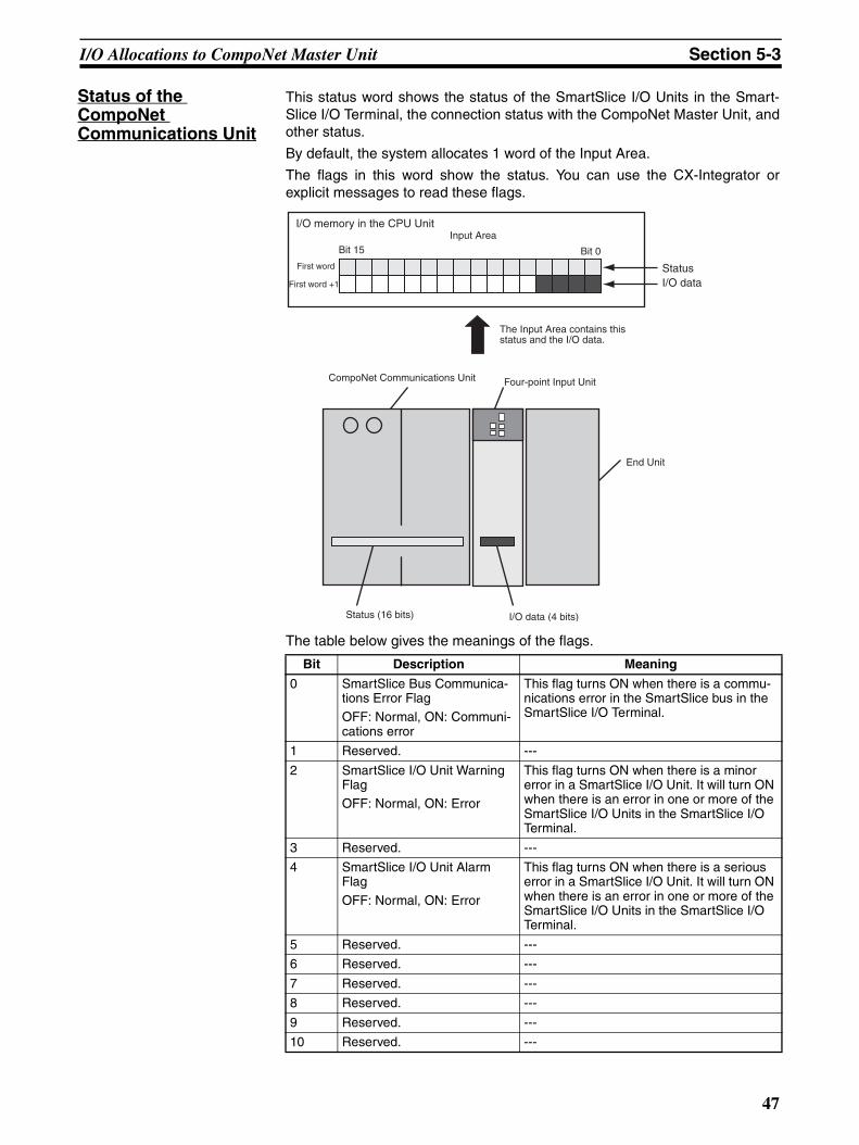
I/O Allocations to CompoNet Master Unit Section 5-3
Status of the CompoNet Communications Unit
This status word shows the status of the SmartSlice I/O Units in the Smart-Slice I/O Terminal, the connection status with the CompoNet Master Unit, andother status.
By default, the system allocates 1 word of the Input Area.
The flags in this word show the status. You can use the CX-Integrator orexplicit messages to read these flags.
The table below gives the meanings of the flags.
Bit Description Meaning
0 SmartSlice Bus Communica-tions Error Flag OFF: Normal, ON: Communi-cations error
This flag turns ON when there is a commu-nications error in the SmartSlice bus in the SmartSlice I/O Terminal.
1 Reserved. ---
2 SmartSlice I/O Unit Warning Flag OFF: Normal, ON: Error
This flag turns ON when there is a minor error in a SmartSlice I/O Unit. It will turn ON when there is an error in one or more of the SmartSlice I/O Units in the SmartSlice I/O Terminal.
3 Reserved. ---
4 SmartSlice I/O Unit Alarm Flag
OFF: Normal, ON: Error
This flag turns ON when there is a serious error in a SmartSlice I/O Unit. It will turn ON when there is an error in one or more of the SmartSlice I/O Units in the SmartSlice I/O Terminal.
5 Reserved. ---
6 Reserved. ---
7 Reserved. ---
8 Reserved. ---
9 Reserved. ---
10 Reserved. ---
I/O memory in the CPU Unit
Bit 15Input Area
Bit 0First word
First word +1
Status I/O data
The Input Area contains this status and the I/O data.
CompoNet Communications Unit Four-point Input Unit
End Unit
Status (16 bits) I/O data (4 bits)
47
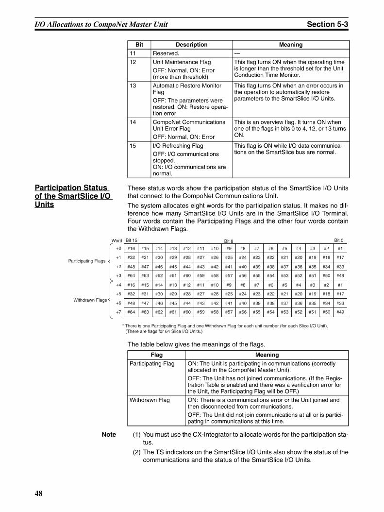
I/O Allocations to CompoNet Master Unit Section 5-3
Participation Status of the SmartSlice I/O Units
These status words show the participation status of the SmartSlice I/O Unitsthat connect to the CompoNet Communications Unit.
The system allocates eight words for the participation status. It makes no dif-ference how many SmartSlice I/O Units are in the SmartSlice I/O Terminal.Four words contain the Participating Flags and the other four words containthe Withdrawn Flags.
The table below gives the meanings of the flags.
Note (1) You must use the CX-Integrator to allocate words for the participation sta-tus.
(2) The TS indicators on the SmartSlice I/O Units also show the status of thecommunications and the status of the SmartSlice I/O Units.
11 Reserved. ---
12 Unit Maintenance Flag OFF: Normal, ON: Error (more than threshold)
This flag turns ON when the operating time is longer than the threshold set for the Unit Conduction Time Monitor.
13 Automatic Restore Monitor Flag OFF: The parameters were restored. ON: Restore opera-tion error
This flag turns ON when an error occurs in the operation to automatically restore parameters to the SmartSlice I/O Units.
14 CompoNet Communications Unit Error Flag OFF: Normal, ON: Error
This is an overview flag. It turns ON when one of the flags in bits 0 to 4, 12, or 13 turns ON.
15 I/O Refreshing Flag OFF: I/O communications stopped. ON: I/O communications are normal.
This flag is ON while I/O data communica-tions on the SmartSlice bus are normal.
Bit Description Meaning
#17
#11 #10#12#13#14#15#16
#18#19#20#21#22#23#24#25#27 #26#28#29#30#31#32
#33#34#35#36#37#38#39#40#41#43 #42#44#45#46#47#48
#49#50#51#52#53#54#55#56#57#59 #58#60#61#62#63#64
#1#2#3#4#5#6#7#8#9+0
+1
+2
+3
#17
#11 #10#12#13#14#15#16
#18#19#20#21#22#23#24#25#27 #26#28#29#30#31#32
#33#34#35#36#37#38#39#40#41#43 #42#44#45#46#47#48
#49#50#51#52#53#54#55#56#57#59 #58#60#61#62#63#64
#1#2#3#4#5#6#7#8#9+4
+5
+6
+7
Word Bit 15 Bit 8 Bit 0
Participating Flags
Withdrawn Flags
* There is one Participating Flag and one Withdrawn Flag for each unit number (for each Slice I/O Unit). (There are flags for 64 Slice I/O Units.)
Flag Meaning
Participating Flag ON: The Unit is participating in communications (correctly allocated in the CompoNet Master Unit). OFF: The Unit has not joined communications. (If the Regis-tration Table is enabled and there was a verification error for the Unit, the Participating Flag will be OFF.)
Withdrawn Flag ON: There is a communications error or the Unit joined and then disconnected from communications. OFF: The Unit did not join communications at all or is partici-pating in communications at this time.
48
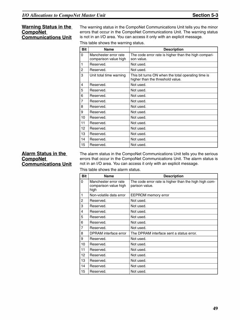
I/O Allocations to CompoNet Master Unit Section 5-3
Warning Status in the CompoNet Communications Unit
The warning status in the CompoNet Communications Unit tells you the minorerrors that occur in the CompoNet Communications Unit. The warning statusis not in an I/O area. You can access it only with an explicit message.
This table shows the warning status.
Alarm Status in the CompoNet Communications Unit
The alarm status in the CompoNet Communications Unit tells you the seriouserrors that occur in the CompoNet Communications Unit. The alarm status isnot in an I/O area. You can access it only with an explicit message.
This table shows the alarm status.
Bit Name Description
0 Manchester error rate comparison value high
The code error rate is higher than the high compari-son value.
1 Reserved. Not used.
2 Reserved. Not used.
3 Unit total time warning This bit turns ON when the total operating time is higher than the threshold value.
4 Reserved. Not used.
5 Reserved. Not used.
6 Reserved. Not used.
7 Reserved. Not used.
8 Reserved. Not used.
9 Reserved. Not used.
10 Reserved. Not used.
11 Reserved. Not used.
12 Reserved. Not used.
13 Reserved. Not used.
14 Reserved. Not used.
15 Reserved. Not used.
Bit Name Description
0 Manchester error rate comparison value high high
The code error rate is higher than the high high com-parison value.
1 Non-volatile data error EEPROM memory error
2 Reserved. Not used.
3 Reserved. Not used.
4 Reserved. Not used.
5 Reserved. Not used.
6 Reserved. Not used.
7 Reserved. Not used.
8 DPRAM interface error The DPRAM interface sent a status error.
9 Reserved. Not used.
10 Reserved. Not used.
11 Reserved. Not used.
12 Reserved. Not used.
13 Reserved. Not used.
14 Reserved. Not used.
15 Reserved. Not used.
49
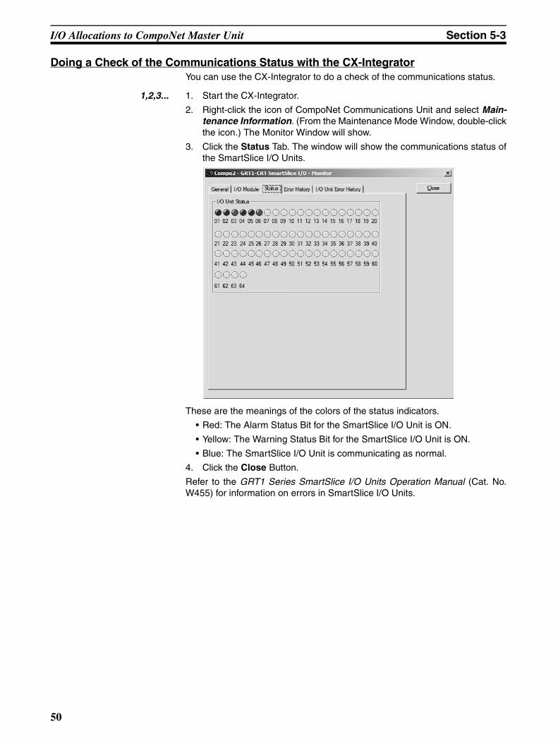
I/O Allocations to CompoNet Master Unit Section 5-3
Doing a Check of the Communications Status with the CX-IntegratorYou can use the CX-Integrator to do a check of the communications status.
1,2,3... 1. Start the CX-Integrator.
2. Right-click the icon of CompoNet Communications Unit and select Main-tenance Information. (From the Maintenance Mode Window, double-clickthe icon.) The Monitor Window will show.
3. Click the Status Tab. The window will show the communications status ofthe SmartSlice I/O Units.
These are the meanings of the colors of the status indicators.
• Red: The Alarm Status Bit for the SmartSlice I/O Unit is ON.
• Yellow: The Warning Status Bit for the SmartSlice I/O Unit is ON.
• Blue: The SmartSlice I/O Unit is communicating as normal.
4. Click the Close Button.
Refer to the GRT1 Series SmartSlice I/O Units Operation Manual (Cat. No.W455) for information on errors in SmartSlice I/O Units.
50
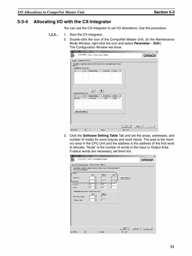
I/O Allocations to CompoNet Master Unit Section 5-3
5-3-4 Allocating I/O with the CX-IntegratorYou can use the CX-Integrator to set I/O allocations. Use this procedure.
1,2,3... 1. Start the CX-Integrator.
2. Double-click the icon of the CompoNet Master Unit. (In the MaintenanceMode Window, right-click the icon and select Parameter − Edit.) The Configuration Window will show.
3. Click the Software Setting Table Tab and set the areas, addresses, andnumber of nodes for word outputs and word inputs. The area is the mem-ory area in the CPU Unit and the address is the address of the first wordto allocate. “Node” is the number of words in the Input or Output Area. If status words are necessary, set them too.
51
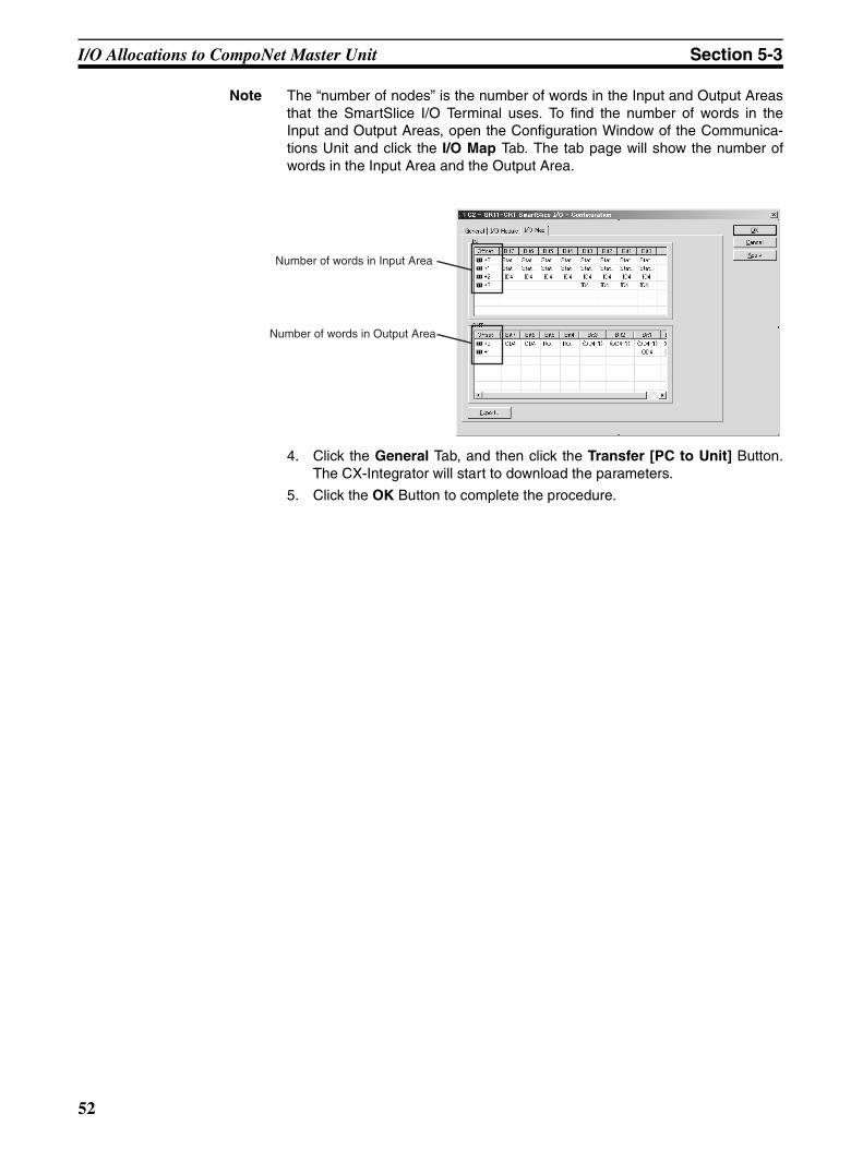
I/O Allocations to CompoNet Master Unit Section 5-3
Note The “number of nodes” is the number of words in the Input and Output Areasthat the SmartSlice I/O Terminal uses. To find the number of words in theInput and Output Areas, open the Configuration Window of the Communica-tions Unit and click the I/O Map Tab. The tab page will show the number ofwords in the Input Area and the Output Area.
4. Click the General Tab, and then click the Transfer [PC to Unit] Button.The CX-Integrator will start to download the parameters.
5. Click the OK Button to complete the procedure.
Number of words in Input Area
Number of words in Output Area
52
SECTION 6Smart Functions
This section tells you about the many smart functions of the SmartSlice system.
6-1 Overview of Smart Functions . . . . . . . . . . . . . . . . . . . . . . . . . . . . . . . . . . . . . 54
6-2 Registration Table . . . . . . . . . . . . . . . . . . . . . . . . . . . . . . . . . . . . . . . . . . . . . . 54
6-2-1 Making a Registration Table. . . . . . . . . . . . . . . . . . . . . . . . . . . . . . . 54
6-2-2 Verifying the Registration Table . . . . . . . . . . . . . . . . . . . . . . . . . . . . 55
6-2-3 Clearing the Registration Table . . . . . . . . . . . . . . . . . . . . . . . . . . . . 56
6-3 Backup Function . . . . . . . . . . . . . . . . . . . . . . . . . . . . . . . . . . . . . . . . . . . . . . . 57
6-3-1 Backup Procedure. . . . . . . . . . . . . . . . . . . . . . . . . . . . . . . . . . . . . . . 57
6-3-2 Doing a Check of the Backup Results . . . . . . . . . . . . . . . . . . . . . . . 57
6-4 Automatic Restore Function . . . . . . . . . . . . . . . . . . . . . . . . . . . . . . . . . . . . . . 58
6-4-1 Restore Procedure. . . . . . . . . . . . . . . . . . . . . . . . . . . . . . . . . . . . . . . 58
6-4-2 Doing a Check of the Restore Results . . . . . . . . . . . . . . . . . . . . . . . 59
6-5 Replacing Units Online . . . . . . . . . . . . . . . . . . . . . . . . . . . . . . . . . . . . . . . . . . 59
6-6 Automatic Baud Rate Recognition . . . . . . . . . . . . . . . . . . . . . . . . . . . . . . . . . 59
6-7 Software Setting of I/O Allocations . . . . . . . . . . . . . . . . . . . . . . . . . . . . . . . . 60
6-7-1 Starting in Software I/O Allocation Mode . . . . . . . . . . . . . . . . . . . . 62
6-7-2 Making, Downloading, and Clearing the Software Setting Table . . 63
6-7-3 Showing the Settings . . . . . . . . . . . . . . . . . . . . . . . . . . . . . . . . . . . . 67
6-7-4 Editing Parameters of SmartSlice I/O Units . . . . . . . . . . . . . . . . . . . 70
6-8 Unit Conduction Time Monitor. . . . . . . . . . . . . . . . . . . . . . . . . . . . . . . . . . . . 71
6-8-1 Monitoring the Unit Conduction Time . . . . . . . . . . . . . . . . . . . . . . . 72
6-8-2 Setting the Threshold . . . . . . . . . . . . . . . . . . . . . . . . . . . . . . . . . . . . 72
6-9 Unit Comments . . . . . . . . . . . . . . . . . . . . . . . . . . . . . . . . . . . . . . . . . . . . . . . . 73
6-9-1 Reading Comments. . . . . . . . . . . . . . . . . . . . . . . . . . . . . . . . . . . . . . 74
6-9-2 Writing Comments . . . . . . . . . . . . . . . . . . . . . . . . . . . . . . . . . . . . . . 74
6-10 Network Communications Error History Monitor . . . . . . . . . . . . . . . . . . . . . 75
6-10-1 Reading the Error History. . . . . . . . . . . . . . . . . . . . . . . . . . . . . . . . . 75
6-11 I/O Communications Error History Monitor . . . . . . . . . . . . . . . . . . . . . . . . . 76
6-11-1 Reading the Error History. . . . . . . . . . . . . . . . . . . . . . . . . . . . . . . . . 77
6-12 Last Maintenance Date . . . . . . . . . . . . . . . . . . . . . . . . . . . . . . . . . . . . . . . . . . 77
6-12-1 Reading the Last Maintenance Date . . . . . . . . . . . . . . . . . . . . . . . . . 77
6-12-2 Writing the Last Maintenance Date . . . . . . . . . . . . . . . . . . . . . . . . . 78
53
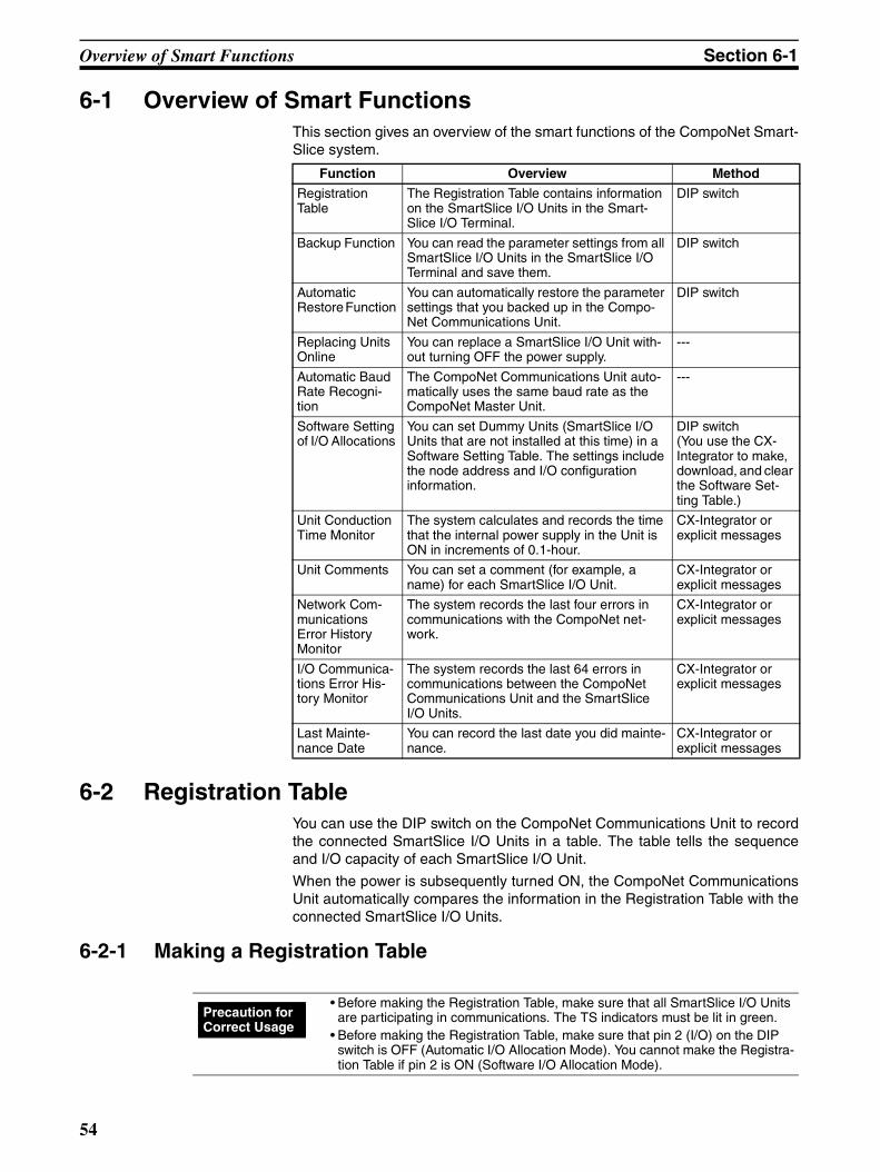
Overview of Smart Functions Section 6-1
6-1 Overview of Smart Functions This section gives an overview of the smart functions of the CompoNet Smart-Slice system.
6-2 Registration TableYou can use the DIP switch on the CompoNet Communications Unit to recordthe connected SmartSlice I/O Units in a table. The table tells the sequenceand I/O capacity of each SmartSlice I/O Unit.
When the power is subsequently turned ON, the CompoNet CommunicationsUnit automatically compares the information in the Registration Table with theconnected SmartSlice I/O Units.
6-2-1 Making a Registration Table
Function Overview Method
Registration Table
The Registration Table contains information on the SmartSlice I/O Units in the Smart-Slice I/O Terminal.
DIP switch
Backup Function You can read the parameter settings from all SmartSlice I/O Units in the SmartSlice I/O Terminal and save them.
DIP switch
Automatic Restore Function
You can automatically restore the parameter settings that you backed up in the Compo-Net Communications Unit.
DIP switch
Replacing Units Online
You can replace a SmartSlice I/O Unit with-out turning OFF the power supply.
---
Automatic Baud Rate Recogni-tion
The CompoNet Communications Unit auto-matically uses the same baud rate as the CompoNet Master Unit.
---
Software Setting of I/O Allocations
You can set Dummy Units (SmartSlice I/O Units that are not installed at this time) in a Software Setting Table. The settings include the node address and I/O configuration information.
DIP switch(You use the CX-Integrator to make, download, and clear the Software Set-ting Table.)
Unit Conduction Time Monitor
The system calculates and records the time that the internal power supply in the Unit is ON in increments of 0.1-hour.
CX-Integrator or explicit messages
Unit Comments You can set a comment (for example, a name) for each SmartSlice I/O Unit.
CX-Integrator or explicit messages
Network Com-munications Error History Monitor
The system records the last four errors in communications with the CompoNet net-work.
CX-Integrator or explicit messages
I/O Communica-tions Error His-tory Monitor
The system records the last 64 errors in communications between the CompoNet Communications Unit and the SmartSlice I/O Units.
CX-Integrator or explicit messages
Last Mainte-nance Date
You can record the last date you did mainte-nance.
CX-Integrator or explicit messages
• Before making the Registration Table, make sure that all SmartSlice I/O Units are participating in communications. The TS indicators must be lit in green.
• Before making the Registration Table, make sure that pin 2 (I/O) on the DIP switch is OFF (Automatic I/O Allocation Mode). You cannot make the Registra-tion Table if pin 2 is ON (Software I/O Allocation Mode).
Precaution for Correct Usage
54
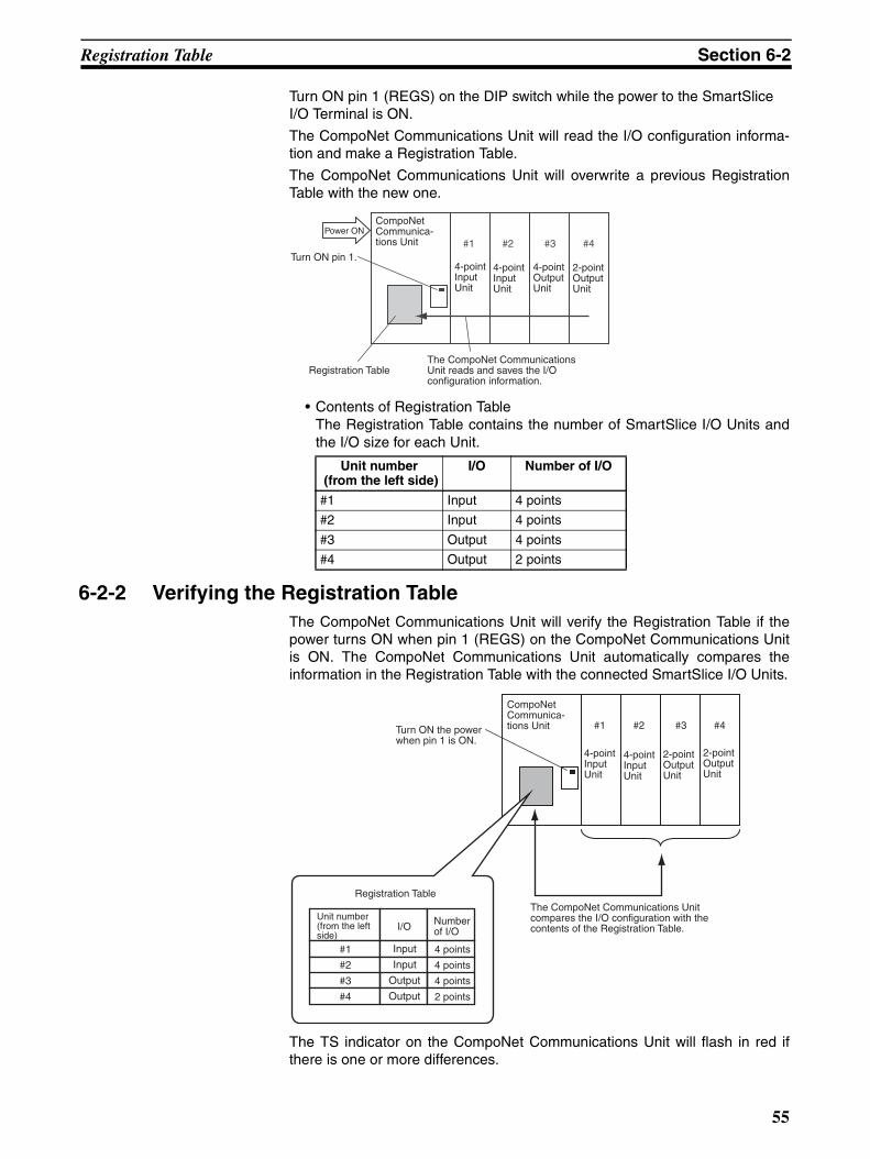
Registration Table Section 6-2
Turn ON pin 1 (REGS) on the DIP switch while the power to the SmartSlice I/O Terminal is ON.
The CompoNet Communications Unit will read the I/O configuration informa-tion and make a Registration Table.
The CompoNet Communications Unit will overwrite a previous RegistrationTable with the new one.
• Contents of Registration TableThe Registration Table contains the number of SmartSlice I/O Units andthe I/O size for each Unit.
6-2-2 Verifying the Registration TableThe CompoNet Communications Unit will verify the Registration Table if thepower turns ON when pin 1 (REGS) on the CompoNet Communications Unitis ON. The CompoNet Communications Unit automatically compares theinformation in the Registration Table with the connected SmartSlice I/O Units.
The TS indicator on the CompoNet Communications Unit will flash in red ifthere is one or more differences.
Unit number (from the left side)
I/O Number of I/O
#1 Input 4 points
#2 Input 4 points
#3 Output 4 points
#4 Output 2 points
#1 #2 #3 #4Power ON
Turn ON pin 1.
Registration TableThe CompoNet Communications Unit reads and saves the I/O configuration information.
CompoNet Communica-tions Unit
4-point Input Unit
4-point Input Unit
4-point Output Unit
2-point Output Unit
#1 #2 #3 #4
#1
#2
#3
#4
Input
Input
Output
Output
I/O
4 points
4 points
4 points
2 points
Turn ON the power when pin 1 is ON.
CompoNet Communica-tions Unit
4-point Input Unit
2-point Output Unit
2-point Output Unit
4-point Input Unit
Registration Table
Unit number (from the left side)
Number of I/O
The CompoNet Communications Unit compares the I/O configuration with the contents of the Registration Table.
55
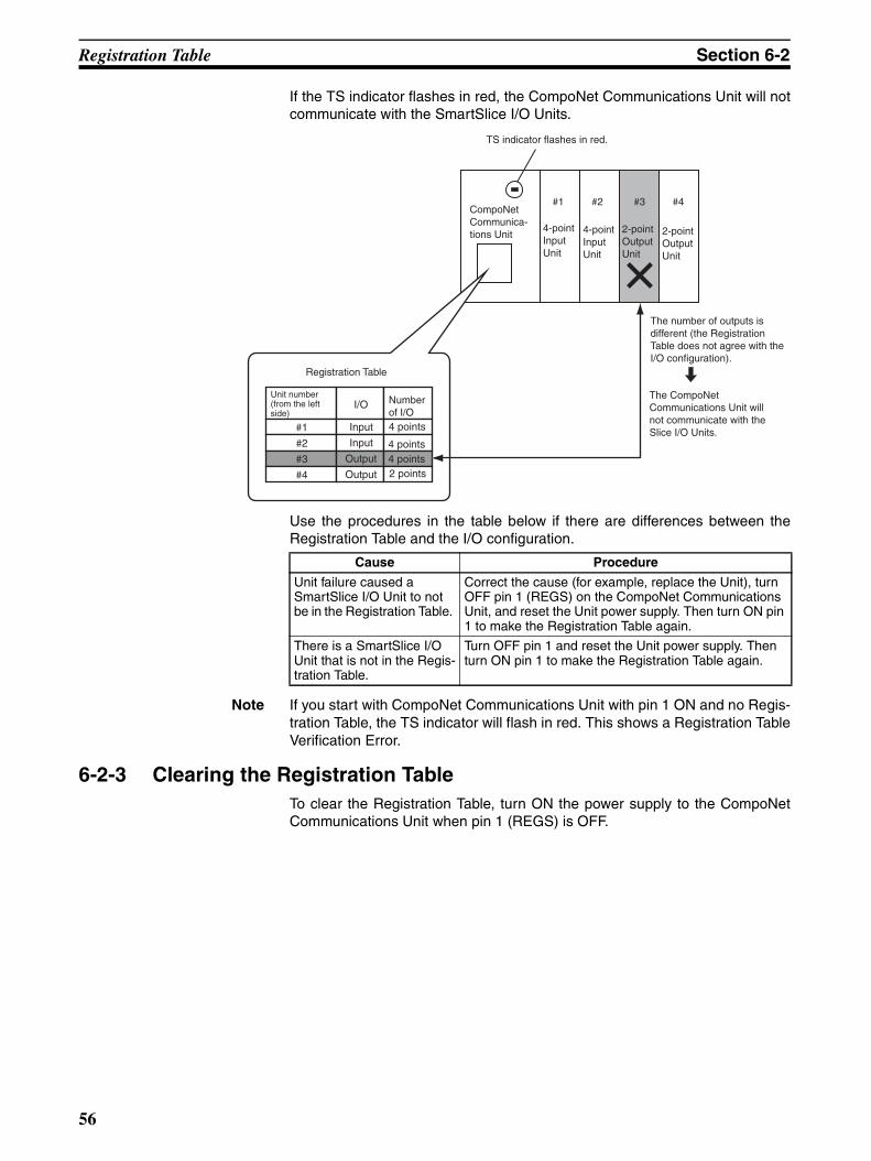
Registration Table Section 6-2
If the TS indicator flashes in red, the CompoNet Communications Unit will notcommunicate with the SmartSlice I/O Units.
Use the procedures in the table below if there are differences between theRegistration Table and the I/O configuration.
Note If you start with CompoNet Communications Unit with pin 1 ON and no Regis-tration Table, the TS indicator will flash in red. This shows a Registration TableVerification Error.
6-2-3 Clearing the Registration TableTo clear the Registration Table, turn ON the power supply to the CompoNetCommunications Unit when pin 1 (REGS) is OFF.
#1 #2 #3 #4
#1
#2
#3
#4
Input
Input
Output
Output
I/O
TS indicator flashes in red.
CompoNet Communica-tions Unit
4-point Input Unit
4-point Input Unit
2-point Output Unit
2-point Output Unit
Registration Table
Unit number (from the left side)
Number of I/O 4 points
4 points4 points2 points
The number of outputs is different (the Registration Table does not agree with the I/O configuration).
The CompoNet Communications Unit will not communicate with the Slice I/O Units.
Cause Procedure
Unit failure caused a SmartSlice I/O Unit to not be in the Registration Table.
Correct the cause (for example, replace the Unit), turn OFF pin 1 (REGS) on the CompoNet Communications Unit, and reset the Unit power supply. Then turn ON pin 1 to make the Registration Table again.
There is a SmartSlice I/O Unit that is not in the Regis-tration Table.
Turn OFF pin 1 and reset the Unit power supply. Then turn ON pin 1 to make the Registration Table again.
56
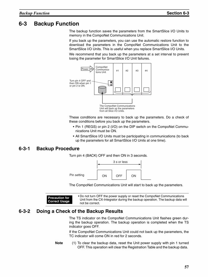
Backup Function Section 6-3
6-3 Backup FunctionThe backup function saves the parameters from the SmartSlice I/O Units tomemory in the CompoNet Communications Unit.
If you back up the parameters, you can use the automatic restore function todownload the parameters in the CompoNet Communications Unit to theSmartSlice I/O Units. This is useful when you replace SmartSlice I/O Units.
We recommend that you back up the parameters at a set interval to preventlosing the parameter for SmartSlice I/O Unit failures.
These conditions are necessary to back up the parameters. Do a check ofthese conditions before you back up the parameters.
• Pin 1 (REGS) or pin 2 (I/O) on the DIP switch on the CompoNet Commu-nications Unit must be ON.
• All SmartSlice I/O Units must be participating in communications (to backup the parameters for all SmartSlice I/O Units at one time).
6-3-1 Backup ProcedureTurn pin 4 (BACK) OFF and then ON in 3 seconds.
The CompoNet Communications Unit will start to back up the parameters.
6-3-2 Doing a Check of the Backup ResultsThe TS indicator on the CompoNet Communications Unit flashes green dur-ing the backup operation. The backup operation is completed when the TSindicator goes OFF.
If the CompoNet Communications Unit could not back up the parameters, theTC indicator will come ON in red for 2 seconds.
Note (1) To clear the backup data, reset the Unit power supply with pin 1 turnedOFF. This operation will clear the Registration Table and the backup data.
#1 #2 #3 #4
CompoNet Communica-tions Unit
Power ON
Turn pin 4 OFF and then ON when pin 1 or pin 2 is ON.
The CompoNet Communications Unit will back up the parameters from all Slice I/O Units.
ON OFF ON
3 s or less
Pin setting
• Do not turn OFF the power supply or reset the CompoNet Communications Unit from the CX-Integrator during the backup operation. The backup data will not be correct.
Precaution for Correct Usage
57
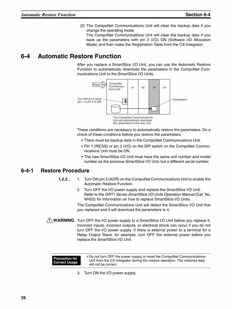
Automatic Restore Function Section 6-4
(2) The CompoNet Communications Unit will clear the backup data if youchange the operating mode. The CompoNet Communications Unit will clear the backup data if youback up the parameters with pin 2 (I/O) ON (Software I/O AllocationMode) and then make the Registration Table from the CX-Integrator.
6-4 Automatic Restore FunctionAfter you replace a SmartSlice I/O Unit, you can use the Automatic RestoreFunction to automatically download the parameters in the CompoNet Com-munications Unit to the SmartSlice I/O Units.
These conditions are necessary to automatically restore the parameters. Do acheck of these conditions before you restore the parameters.
• There must be backup data in the CompoNet Communications Unit.
• Pin 1 (REGS) or pin 2 (I/O) on the DIP switch on the CompoNet Commu-nications Unit must be ON.
• The new SmartSlice I/O Unit must have the same unit number and modelnumber as the previous SmartSlice I/O Unit, but a different serial number.
6-4-1 Restore Procedure1,2,3... 1. Turn ON pin 3 (ADR) on the CompoNet Communications Unit to enable the
Automatic Restore Function.
2. Turn OFF the I/O power supply and replace the SmartSlice I/O Unit. Refer to the GRT1 Series SmartSlice I/O Units Operation Manual (Cat. No.W455) for information on how to replace SmartSlice I/O Units.
The CompoNet Communications Unit will detect the SmartSlice I/O Unit thatyou replaced and it will download the parameters to it.
!WARNING Turn OFF the I/O power supply to a SmartSlice I/O Unit before you replace it.Incorrect inputs, incorrect outputs, or electrical shock can occur if you do notturn OFF the I/O power supply. If there is external power to a terminal for aRelay Output Slave, for example, turn OFF the external power before youreplace the SmartSlice I/O Unit.
3. Turn ON the I/O power supply.
#1 #2 #4#3Power ON CompoNet
Communica-tions Unit
Turn ON pin 3 when pin 1 or pin 2 is ON.
Parameters
The CompoNet Communications Unit will automatically download the parameters to the new Unit.
• Do not turn OFF the power supply or reset the CompoNet Communications Unit from the CX-Integrator during the restore operation. The restored data will not be correct.
Precaution for Correct Usage
58

Replacing Units Online Section 6-5
6-4-2 Doing a Check of the Restore ResultsThe TS indicator on the CompoNet Communications Unit flashes green dur-ing the restore operation. The restore operation is completed when the TSindicator stops flashing.
If the CompoNet Communications Unit restored the parameters, it will resetthe SmartSlice I/O Units automatically and the TS indicator on the CompoNetCommunications Unit will come ON in green.
If the CompoNet Communications Unit could not restore the parameters, theTS indicator on the CompoNet Communications Unit will come ON in red for 2seconds. The Automatic Restore Monitor Flag (bit 13 in the status word for theCompoNet Communications Unit) will also turn ON.
If the new SmartSlice I/O Unit is not the same model as the previous Unit, theTS indicator on the CompoNet Communications Unit will flash in red.
6-5 Replacing Units OnlineYou can replace a SmartSlice I/O Unit in the SmartSlice I/O Terminal withoutturning OFF the Unit power supply.
A SmartSlice I/O Unit has a base block, main block, and terminal block. Whenyou replace a SmartSlice I/O Unit, do not replace the base block and replacethe other blocks.
Communications with the other SmartSlice I/O Units will continue while youreplace the SmartSlice I/O Unit.
If you back up the parameters, you can turn ON pin 3 (ADR) with pin 1(REGS) or pin 2 (I/O) ON to automatically restore the parameters.
Refer to the GRT1 Series SmartSlice I/O Units Operation Manual (Cat. No.W455) for information on how to replace SmartSlice I/O Units.
!WARNING Turn OFF the I/O power supply to a SmartSlice I/O Unit before you replace it.Incorrect inputs, incorrect outputs, or electrical shock can occur if you do notturn OFF the I/O power supply. If there is external power to a terminal for aRelay Output Slave, for example, turn OFF the external power before youreplace the SmartSlice I/O Unit.
6-6 Automatic Baud Rate Recognition The CompoNet Communications Unit will automatically detect the baud rateset in the CompoNet Master Unit and use it for communications with the Com-poNet Master Unit.
• Replace only one SmartSlice I/O Unit at a time. • Always replace a SmartSlice I/O Unit with a Unit of the same model number. If
you use a different model, incorrect outputs can occur or restoring the param-eters will not be possible.
• If it is necessary to replace the base block, turn OFF the unit power supply and the I/O power supplies and replace the full SmartSlice I/O Unit. You can also use the Automatic Restore Function after you replace the full SmartSlice I/O Unit.
Precaution for Correct Usage
59
Software Setting of I/O Allocations Section 6-7
The CompoNet Communications Unit will set the baud rate when it estab-lishes communications with the CompoNet Master Unit. It will save the baudrate until the power supply is turned OFF.
Note If you change the baud rate of the CompoNet Master Unit, reset the powersupply of the CompoNet Communications Unit.
6-7 Software Setting of I/O Allocations You can set Dummy Units in a Software Setting Table for SmartSlice I/O Unitsthat are not in the SmartSlice I/O Terminal. The settings include the nodenumbers and I/O configurations.
When you then add the SmartSlice I/O Units, it will not be necessary for youto set the unit numbers or I/O configurations. It will also not be necessary tochange the ladder programming very much.
The Software Setting Table contains the I/O configuration information (includ-ing the Dummy Units). You can use the CX-Integrator to set or read it.
60
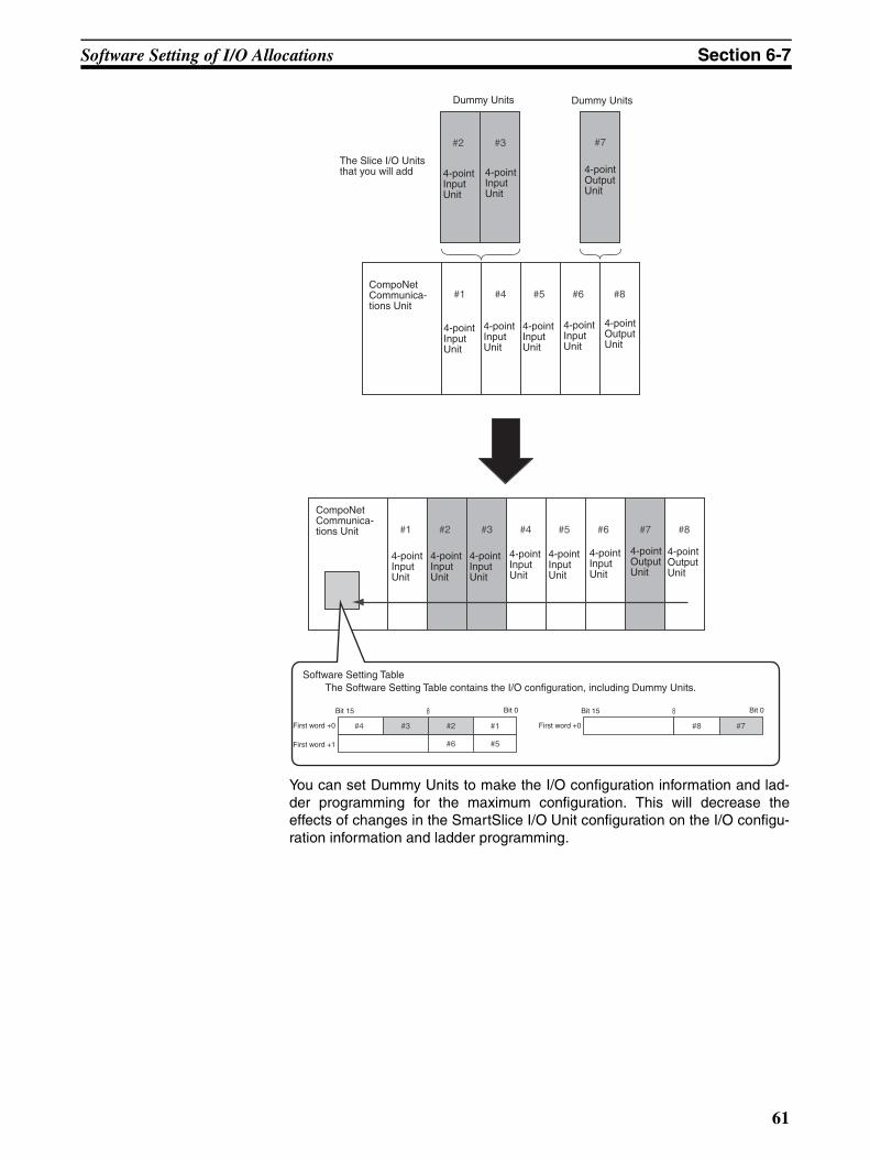
Software Setting of I/O Allocations Section 6-7
You can set Dummy Units to make the I/O configuration information and lad-der programming for the maximum configuration. This will decrease theeffects of changes in the SmartSlice I/O Unit configuration on the I/O configu-ration information and ladder programming.
#1 #2 #3 #4 #5 #6 #7 #8
#1
#2 #3
#4 #5 #6
#7
#8
8
#4 #3 #2 #1
#6 #5
Dummy Units Dummy Units
The Slice I/O Units that you will add 4-point
Input Unit
4-point Input Unit
4-point Output Unit
4-point Output Unit
4-point Input Unit
4-point Input Unit
4-point Input Unit
4-point Input Unit
CompoNet Communica-tions Unit
Software Setting Table The Software Setting Table contains the I/O configuration, including Dummy Units.
CompoNet Communica-tions Unit
4-point Output Unit
4-point Input Unit
4-point Input Unit
4-point Input Unit
4-point Input Unit
4-point Output Unit
4-point Input Unit
4-point Input Unit
Bit 15 Bit 0
First word +0
First word +1
8
#8 #7
Bit 15 Bit 0
First word +0
61
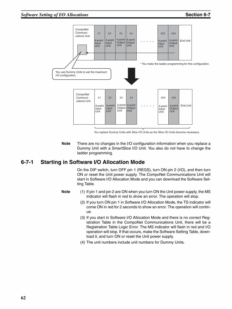
Software Setting of I/O Allocations Section 6-7
Note There are no changes in the I/O configuration information when you replace aDummy Unit with a SmartSlice I/O Unit. You also do not have to change theladder programming.
6-7-1 Starting in Software I/O Allocation ModeOn the DIP switch, turn OFF pin 1 (REGS), turn ON pin 2 (I/O), and then turnON or reset the Unit power supply. The CompoNet Communications Unit willstart in Software I/O Allocation Mode and you can download the Software Set-ting Table.
Note (1) If pin 1 and pin 2 are ON when you turn ON the Unit power supply, the MSindicator will flash in red to show an error. The operation will stop.
(2) If you turn ON pin 1 in Software I/O Allocation Mode, the TS indicator willcome ON in red for 2 seconds to show an error. The operation will contin-ue.
(3) If you start in Software I/O Allocation Mode and there is no correct Reg-istration Table in the CompoNet Communications Unit, there will be aRegistration Table Logic Error. The MS indicator will flash in red and I/Ooperation will stop. If that occurs, make the Software Setting Table, down-load it, and turn ON or reset the Unit power supply.
(4) The unit numbers include unit numbers for Dummy Units.
#1 #2 #3 #4 #63 #64
#1 #2 #3 #4 #63 #64
CompoNet Communi-cations Unit
CompoNet Communi-cations Unit
End Unit
End Unit
4-point Output Unit
4-point Input Unit
4-point Input Unit
4-point Output Unit
4-point Output Unit
4-point Input Unit
4-point Output Unit
4-point Input Unit
4-point Input Unit
4-point Output Unit
4-point Output Unit
4-point Input Unit
* You make the ladder programming for this configuration.
You use Dummy Units to set the maximum I/O configuration.
You replace Dummy Units with Slice I/O Units as the Slice I/O Units become necessary.
62
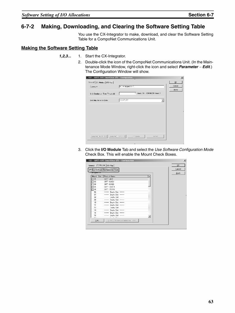
Software Setting of I/O Allocations Section 6-7
6-7-2 Making, Downloading, and Clearing the Software Setting TableYou use the CX-Integrator to make, download, and clear the Software SettingTable for a CompoNet Communications Unit.
Making the Software Setting Table
1,2,3... 1. Start the CX-Integrator.
2. Double-click the icon of the CompoNet Communications Unit. (In the Main-tenance Mode Window, right-click the icon and select Parameter − Edit.) The Configuration Window will show.
3. Click the I/O Module Tab and select the Use Software Configuration ModeCheck Box. This will enable the Mount Check Boxes.
63
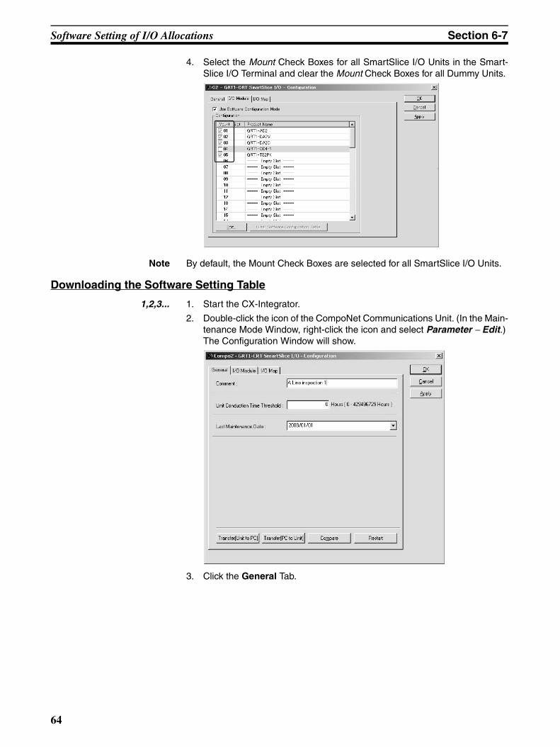
Software Setting of I/O Allocations Section 6-7
4. Select the Mount Check Boxes for all SmartSlice I/O Units in the Smart-Slice I/O Terminal and clear the Mount Check Boxes for all Dummy Units.
Note By default, the Mount Check Boxes are selected for all SmartSlice I/O Units.
Downloading the Software Setting Table
1,2,3... 1. Start the CX-Integrator.
2. Double-click the icon of the CompoNet Communications Unit. (In the Main-tenance Mode Window, right-click the icon and select Parameter − Edit.) The Configuration Window will show.
3. Click the General Tab.
64
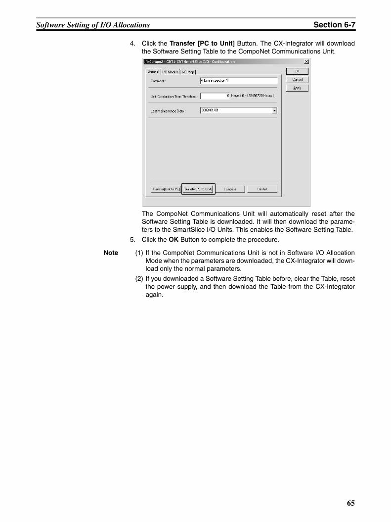
Software Setting of I/O Allocations Section 6-7
4. Click the Transfer [PC to Unit] Button. The CX-Integrator will downloadthe Software Setting Table to the CompoNet Communications Unit.
The CompoNet Communications Unit will automatically reset after theSoftware Setting Table is downloaded. It will then download the parame-ters to the SmartSlice I/O Units. This enables the Software Setting Table.
5. Click the OK Button to complete the procedure.
Note (1) If the CompoNet Communications Unit is not in Software I/O AllocationMode when the parameters are downloaded, the CX-Integrator will down-load only the normal parameters.
(2) If you downloaded a Software Setting Table before, clear the Table, resetthe power supply, and then download the Table from the CX-Integratoragain.
65
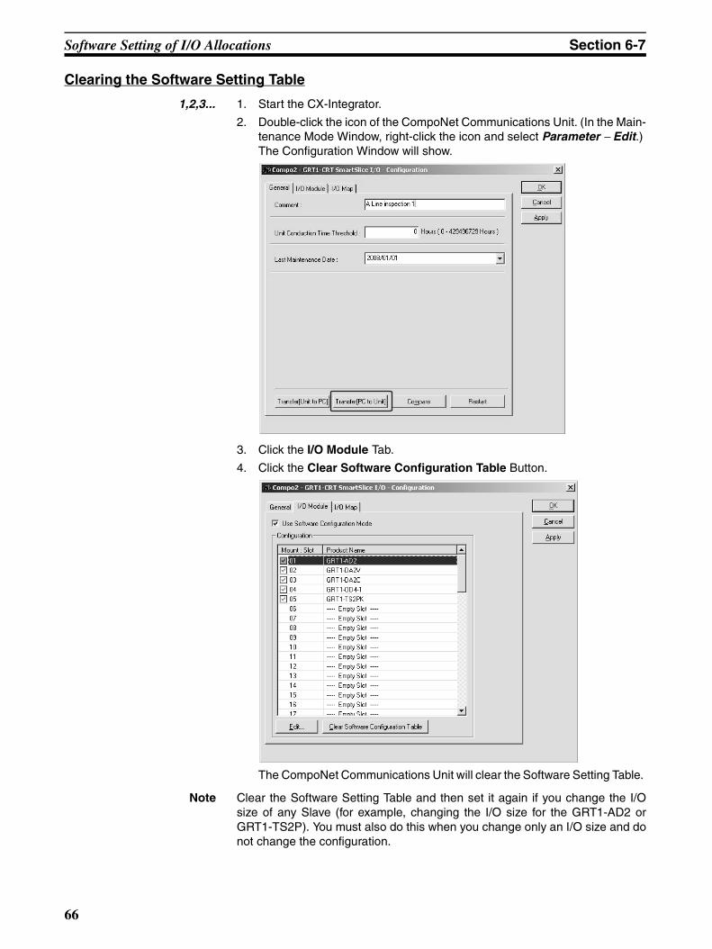
Software Setting of I/O Allocations Section 6-7
Clearing the Software Setting Table
1,2,3... 1. Start the CX-Integrator.
2. Double-click the icon of the CompoNet Communications Unit. (In the Main-tenance Mode Window, right-click the icon and select Parameter − Edit.) The Configuration Window will show.
3. Click the I/O Module Tab.
4. Click the Clear Software Configuration Table Button.
The CompoNet Communications Unit will clear the Software Setting Table.
Note Clear the Software Setting Table and then set it again if you change the I/Osize of any Slave (for example, changing the I/O size for the GRT1-AD2 orGRT1-TS2P). You must also do this when you change only an I/O size and donot change the configuration.
66
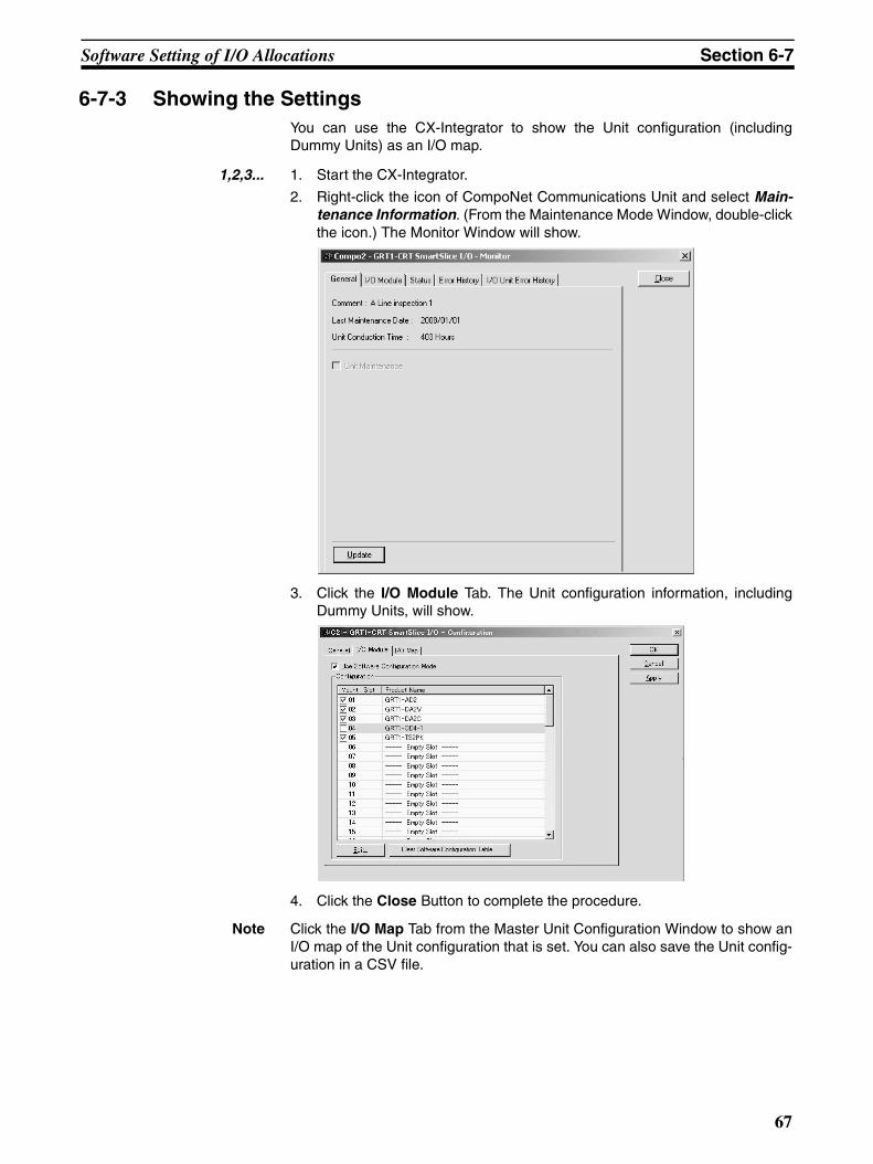
Software Setting of I/O Allocations Section 6-7
6-7-3 Showing the SettingsYou can use the CX-Integrator to show the Unit configuration (includingDummy Units) as an I/O map.
1,2,3... 1. Start the CX-Integrator.
2. Right-click the icon of CompoNet Communications Unit and select Main-tenance Information. (From the Maintenance Mode Window, double-clickthe icon.) The Monitor Window will show.
3. Click the I/O Module Tab. The Unit configuration information, includingDummy Units, will show.
4. Click the Close Button to complete the procedure.
Note Click the I/O Map Tab from the Master Unit Configuration Window to show anI/O map of the Unit configuration that is set. You can also save the Unit config-uration in a CSV file.
67
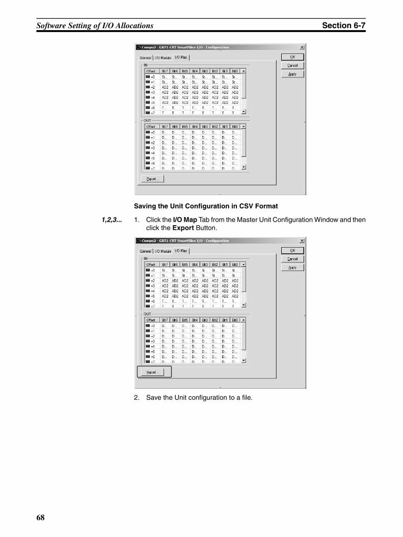
Software Setting of I/O Allocations Section 6-7
Saving the Unit Configuration in CSV Format
1,2,3... 1. Click the I/O Map Tab from the Master Unit Configuration Window and thenclick the Export Button.
2. Save the Unit configuration to a file.
68
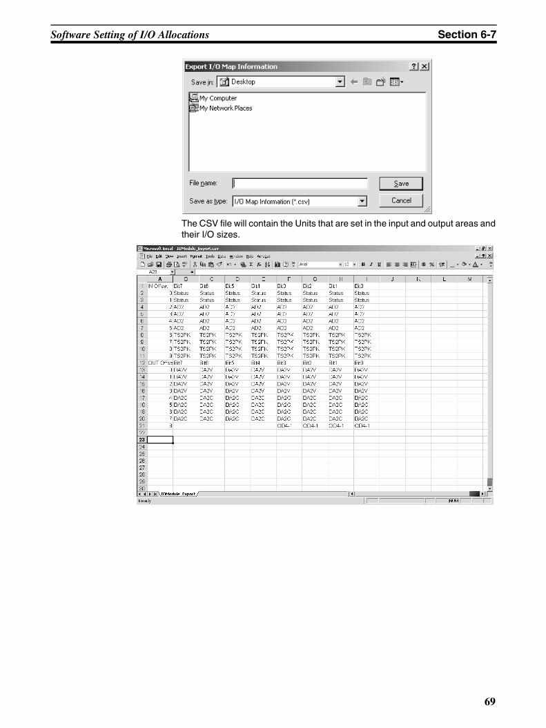
Software Setting of I/O Allocations Section 6-7
The CSV file will contain the Units that are set in the input and output areas andtheir I/O sizes.
69
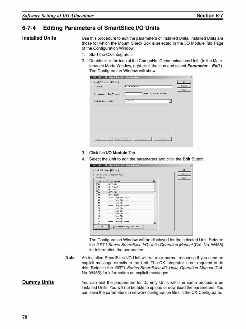
Software Setting of I/O Allocations Section 6-7
6-7-4 Editing Parameters of SmartSlice I/O Units
Installed Units Use this procedure to edit the parameters of installed Units. Installed Units arethose for which the Mount Check Box is selected in the I/O Module Tab Pageof the Configuration Window.
1. Start the CX-Integrator.
2. Double-click the icon of the CompoNet Communications Unit. (In the Main-tenance Mode Window, right-click the icon and select Parameter − Edit.) The Configuration Window will show.
3. Click the I/O Module Tab.
4. Select the Unit to edit the parameters and click the Edit Button.
The Configuration Window will be displayed for the selected Unit. Refer tothe GRT1 Series SmartSlice I/O Units Operation Manual (Cat. No. W455)for information the parameters.
Note An installed SmartSlice I/O Unit will return a normal response if you send anexplicit message directly to the Unit. The CX-Integrator is not required to dothis. Refer to the GRT1 Series SmartSlice I/O Units Operation Manual (Cat.No. W455) for information on explicit messages.
Dummy Units You can edit the parameters for Dummy Units with the same procedure asinstalled Units. You will not be able to upload or download the parameters. Youcan save the parameters in network configuration files in the CX-Configurator.
70
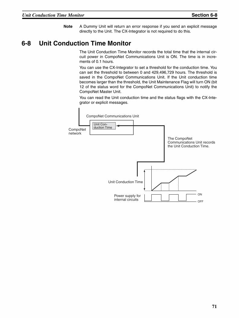
Unit Conduction Time Monitor Section 6-8
Note A Dummy Unit will return an error response if you send an explicit messagedirectly to the Unit. The CX-Integrator is not required to do this.
6-8 Unit Conduction Time MonitorThe Unit Conduction Time Monitor records the total time that the internal cir-cuit power in CompoNet Communications Unit is ON. The time is in incre-ments of 0.1 hours.
You can use the CX-Integrator to set a threshold for the conduction time. Youcan set the threshold to between 0 and 429,496,729 hours. The threshold issaved in the CompoNet Communications Unit. If the Unit conduction timebecomes larger than the threshold, the Unit Maintenance Flag will turn ON (bit12 of the status word for the CompoNet Communications Unit) to notify theCompoNet Master Unit.
You can read the Unit conduction time and the status flags with the CX-Inte-grator or explicit messages.
ON
OFF
CompoNet Communications Unit
CompoNet network
Unit Con-duction Time
Unit Conduction Time
Power supply for internal circuits
The CompoNet Communications Unit records the Unit Conduction Time.
71
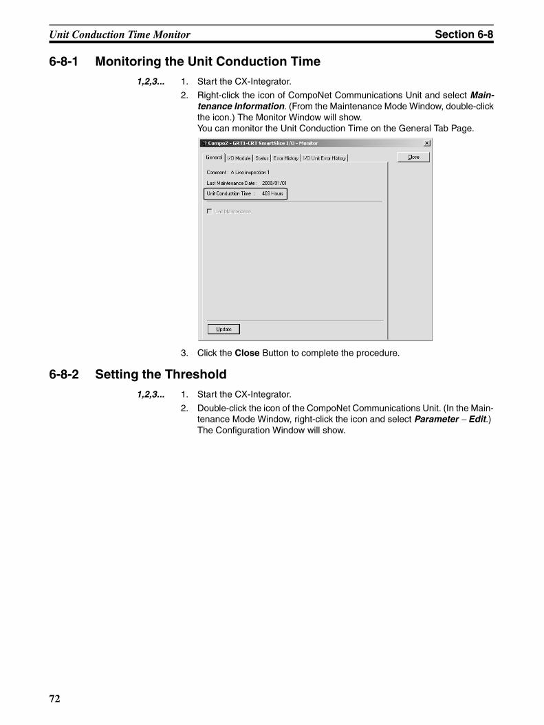
Unit Conduction Time Monitor Section 6-8
6-8-1 Monitoring the Unit Conduction Time1,2,3... 1. Start the CX-Integrator.
2. Right-click the icon of CompoNet Communications Unit and select Main-tenance Information. (From the Maintenance Mode Window, double-clickthe icon.) The Monitor Window will show. You can monitor the Unit Conduction Time on the General Tab Page.
3. Click the Close Button to complete the procedure.
6-8-2 Setting the Threshold1,2,3... 1. Start the CX-Integrator.
2. Double-click the icon of the CompoNet Communications Unit. (In the Main-tenance Mode Window, right-click the icon and select Parameter − Edit.) The Configuration Window will show.
72
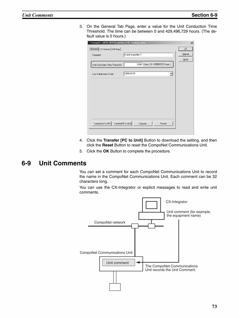
Unit Comments Section 6-9
3. On the General Tab Page, enter a value for the Unit Conduction TimeThreshold. The time can be between 0 and 429,496,729 hours. (The de-fault value is 0 hours.)
4. Click the Transfer [PC to Unit] Button to download the setting, and thenclick the Reset Button to reset the CompoNet Communications Unit.
5. Click the OK Button to complete the procedure.
6-9 Unit CommentsYou can set a comment for each CompoNet Communications Unit to recordthe name in the CompoNet Communications Unit. Each comment can be 32characters long.
You can use the CX-Integrator or explicit messages to read and write unitcomments.
CX-Integrator
CompoNet network
Unit comment (for example, the equipment name)
CompoNet Communications Unit
Unit commentThe CompoNet Communications Unit records the Unit Comment.
73
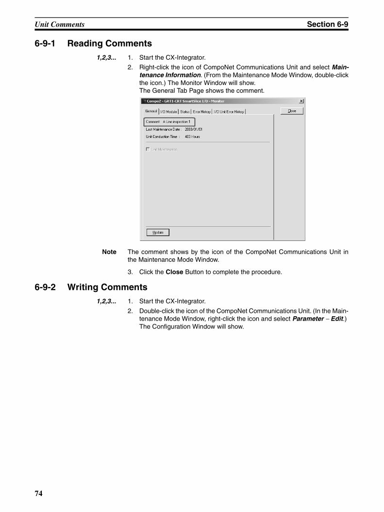
Unit Comments Section 6-9
6-9-1 Reading Comments 1,2,3... 1. Start the CX-Integrator.
2. Right-click the icon of CompoNet Communications Unit and select Main-tenance Information. (From the Maintenance Mode Window, double-clickthe icon.) The Monitor Window will show. The General Tab Page shows the comment.
Note The comment shows by the icon of the CompoNet Communications Unit inthe Maintenance Mode Window.
3. Click the Close Button to complete the procedure.
6-9-2 Writing Comments1,2,3... 1. Start the CX-Integrator.
2. Double-click the icon of the CompoNet Communications Unit. (In the Main-tenance Mode Window, right-click the icon and select Parameter − Edit.) The Configuration Window will show.
74
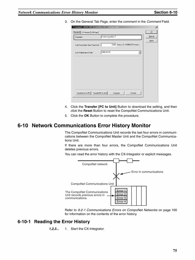
Network Communications Error History Monitor Section 6-10
3. On the General Tab Page, enter the comment in the Comment Field.
4. Click the Transfer [PC to Unit] Button to download the setting, and thenclick the Reset Button to reset the CompoNet Communications Unit.
5. Click the OK Button to complete the procedure.
6-10 Network Communications Error History MonitorThe CompoNet Communications Unit records the last four errors in communi-cations between the CompoNet Master Unit and the CompoNet Communica-tions Unit.
If there are more than four errors, the CompoNet Communications Unitdeletes previous errors.
You can read the error history with the CX-Integrator or explicit messages.
Refer to 9-2-1 Communications Errors on CompoNet Networks on page 100for information on the contents of the error history.
6-10-1 Reading the Error History1,2,3... 1. Start the CX-Integrator.
CompoNet network
Error in communications
CompoNet Communications Unit
The CompoNet Communications Unit records previous errors in communications.
Error 1Error 2Error 3Error 4
75
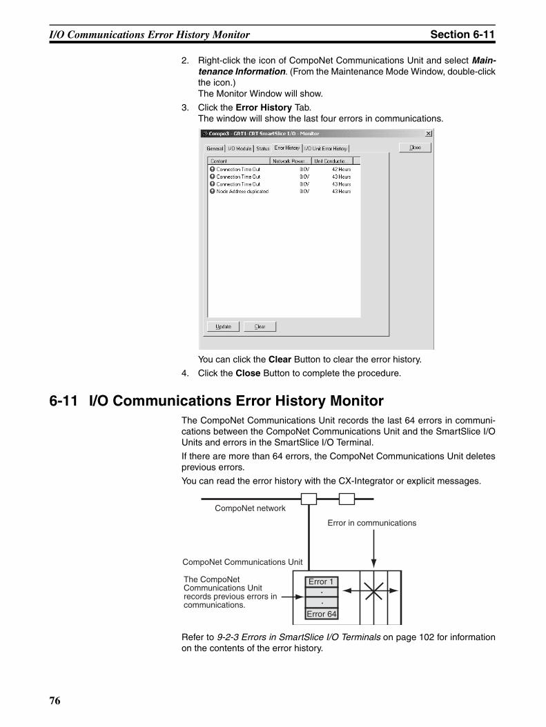
I/O Communications Error History Monitor Section 6-11
2. Right-click the icon of CompoNet Communications Unit and select Main-tenance Information. (From the Maintenance Mode Window, double-clickthe icon.) The Monitor Window will show.
3. Click the Error History Tab. The window will show the last four errors in communications.
You can click the Clear Button to clear the error history.
4. Click the Close Button to complete the procedure.
6-11 I/O Communications Error History MonitorThe CompoNet Communications Unit records the last 64 errors in communi-cations between the CompoNet Communications Unit and the SmartSlice I/OUnits and errors in the SmartSlice I/O Terminal.
If there are more than 64 errors, the CompoNet Communications Unit deletesprevious errors.
You can read the error history with the CX-Integrator or explicit messages.
Refer to 9-2-3 Errors in SmartSlice I/O Terminals on page 102 for informationon the contents of the error history.
CompoNet network
Error in communications
CompoNet Communications Unit
The CompoNet Communications Unit records previous errors in communications.
Error 1
Error 64
76
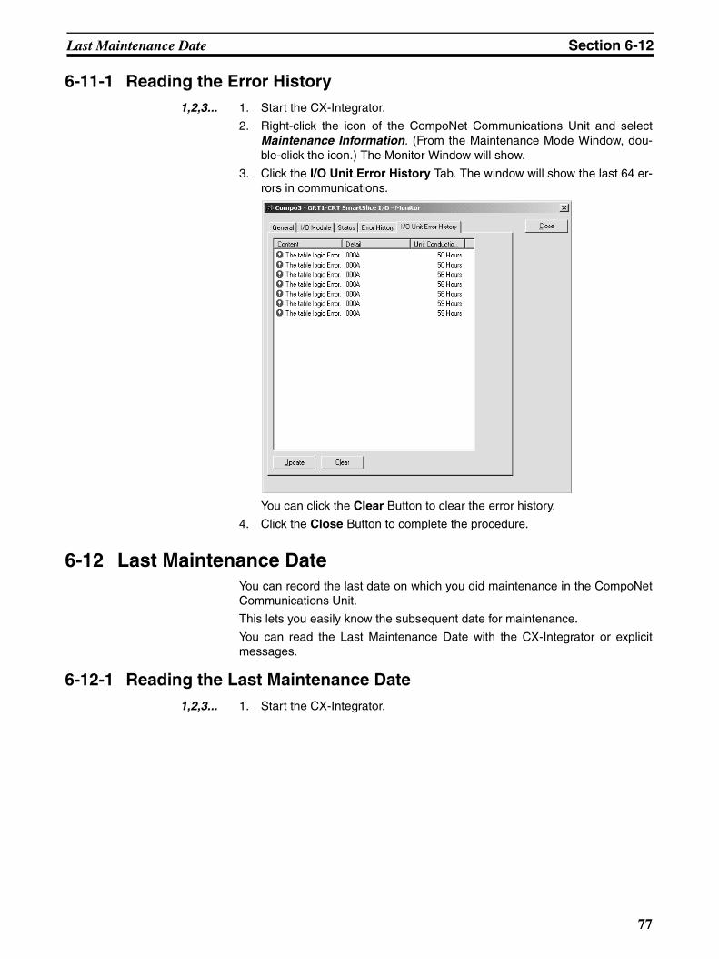
Last Maintenance Date Section 6-12
6-11-1 Reading the Error History1,2,3... 1. Start the CX-Integrator.
2. Right-click the icon of the CompoNet Communications Unit and selectMaintenance Information. (From the Maintenance Mode Window, dou-ble-click the icon.) The Monitor Window will show.
3. Click the I/O Unit Error History Tab. The window will show the last 64 er-rors in communications.
You can click the Clear Button to clear the error history.
4. Click the Close Button to complete the procedure.
6-12 Last Maintenance DateYou can record the last date on which you did maintenance in the CompoNetCommunications Unit.
This lets you easily know the subsequent date for maintenance.
You can read the Last Maintenance Date with the CX-Integrator or explicitmessages.
6-12-1 Reading the Last Maintenance Date1,2,3... 1. Start the CX-Integrator.
77
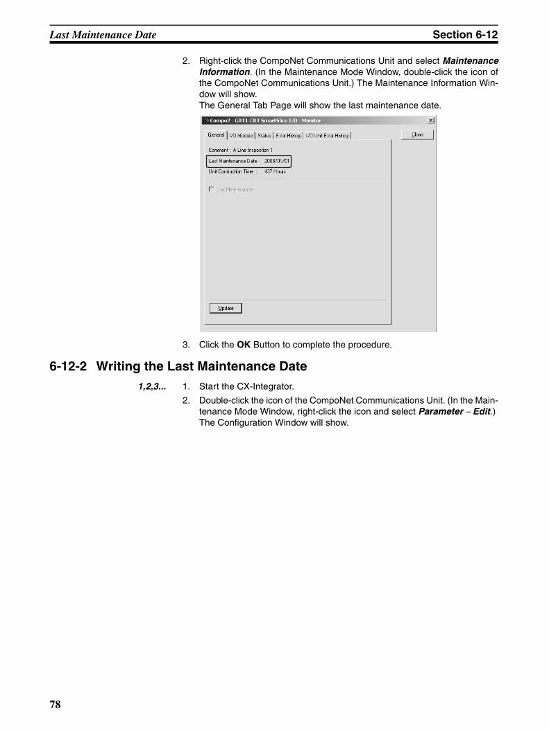
Last Maintenance Date Section 6-12
2. Right-click the CompoNet Communications Unit and select MaintenanceInformation. (In the Maintenance Mode Window, double-click the icon ofthe CompoNet Communications Unit.) The Maintenance Information Win-dow will show. The General Tab Page will show the last maintenance date.
3. Click the OK Button to complete the procedure.
6-12-2 Writing the Last Maintenance Date1,2,3... 1. Start the CX-Integrator.
2. Double-click the icon of the CompoNet Communications Unit. (In the Main-tenance Mode Window, right-click the icon and select Parameter − Edit.) The Configuration Window will show.
78
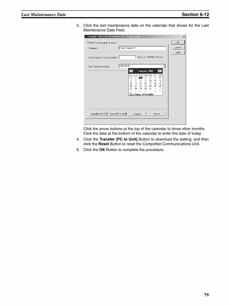
Last Maintenance Date Section 6-12
3. Click the last maintenance date on the calendar that shows for the LastMaintenance Date Field.
Click the arrow buttons at the top of the calendar to show other months. Click the date at the bottom of the calendar to enter the date of today.
4. Click the Transfer [PC to Unit] Button to download the setting, and thenclick the Reset Button to reset the CompoNet Communications Unit.
5. Click the OK Button to complete the procedure.
79

Last Maintenance Date Section 6-12
80
SECTION 7Basic Operation
This section gives the procedures for and an example of operating a SmartSlice system.
7-1 Setting Example and Basic Procedures. . . . . . . . . . . . . . . . . . . . . . . . . . . . . . 82
7-1-1 System Setting Example . . . . . . . . . . . . . . . . . . . . . . . . . . . . . . . . . . 82
7-1-2 Basic Procedures. . . . . . . . . . . . . . . . . . . . . . . . . . . . . . . . . . . . . . . . 83
7-2 Preparing for Work . . . . . . . . . . . . . . . . . . . . . . . . . . . . . . . . . . . . . . . . . . . . . 84
7-2-1 Selecting the SmartSlice I/O Units . . . . . . . . . . . . . . . . . . . . . . . . . . 84
7-2-2 Making Sure That SmartSlice Specifications Are Applicable . . . . . 84
7-3 Hardware Connections and Settings . . . . . . . . . . . . . . . . . . . . . . . . . . . . . . . . 85
7-3-1 Installing a SmartSlice I/O Terminal . . . . . . . . . . . . . . . . . . . . . . . . 85
7-3-2 Connecting the Communications Cables and Power Cables . . . . . . 85
7-3-3 Setting the SmartSlice I/O Terminals . . . . . . . . . . . . . . . . . . . . . . . . 85
7-4 Starting Communications . . . . . . . . . . . . . . . . . . . . . . . . . . . . . . . . . . . . . . . . 87
7-4-1 Making the I/O Tables . . . . . . . . . . . . . . . . . . . . . . . . . . . . . . . . . . . 87
7-4-2 Starting the SmartSlice System . . . . . . . . . . . . . . . . . . . . . . . . . . . . 87
7-5 Making Sure That Operation Is Correct . . . . . . . . . . . . . . . . . . . . . . . . . . . . . 88
7-5-1 Unit Indications . . . . . . . . . . . . . . . . . . . . . . . . . . . . . . . . . . . . . . . . 88
7-5-2 Doing a Check of I/O . . . . . . . . . . . . . . . . . . . . . . . . . . . . . . . . . . . . 88
81
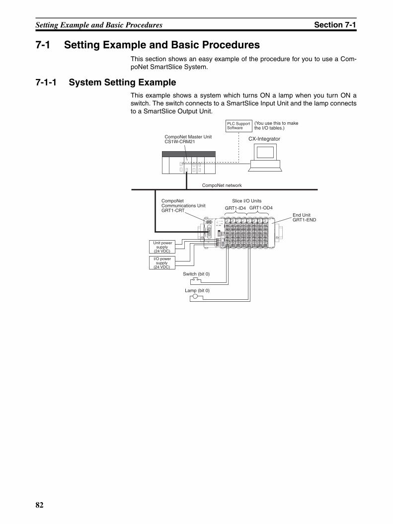
Setting Example and Basic Procedures Section 7-1
7-1 Setting Example and Basic ProceduresThis section shows an easy example of the procedure for you to use a Com-poNet SmartSlice System.
7-1-1 System Setting ExampleThis example shows a system which turns ON a lamp when you turn ON aswitch. The switch connects to a SmartSlice Input Unit and the lamp connectsto a SmartSlice Output Unit.
CX-IntegratorCompoNet Master Unit CS1W-CRM21
PLC Support Software
(You use this to make the I/O tables.)
CompoNet network
CompoNet Communications Unit GRT1-CRT
Slice I/O Units
GRT1-ID4 GRT1-OD4
End Unit GRT1-END
Unit power supply
(24 VDC)
I/O power supply
(24 VDC)
Switch (bit 0)
Lamp (bit 0)
TS0 12 3
TS0 12 3
OD4 ENDGRT1-CRT
INX OUTX
WORDNODE ADR ×10 ×1
(0-63)
BS
|
BS
BD
HB
D L
DC24VINPUT
TS
UNIT PWR
I/O PWR
MS
NS
ON
1234
REGSI/OADR
BACK
UNIT
I/O
V
V
DC24VINPUT
V
V
ID4TS
0 12 3
ID4TS
0 12 3
ID4TS
0 12 3
ID4
A1
A2
A3
A4
A5
A6 B
6B
5B
4B
3B
2B
1
B6
B5
B4
B3
B2
B1A
1A
2A
3A
4A
5A
6
A1
A2
A3
A4
A5
A6
A1
A2
A3
A4
A5
A6
A1
A2
A3
A4
A5
A6
A1
A2
A3
A4
A5
A6
A1
A2
A3
A4
A5
A6
A1
A2
A3
A4
A5
A6B
6B
5B
4B
3B
2B
1
B6
B5
B4
B3
B2
B1
B6
B5
B4
B3
B2
B1
B6
B5
B4
B3
B2
B1
B6
B5
B4
B3
B2
B1
B6
B5
B4
B3
B2
B1
TS0 12 3
OD4TS
0 12 3
OD4TS
0 12 3
OD4
82
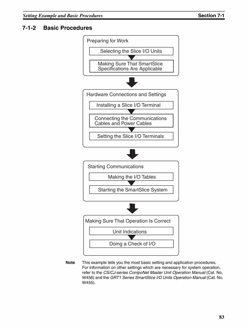
Setting Example and Basic Procedures Section 7-1
7-1-2 Basic Procedures
Note This example tells you the most basic setting and application procedures. For information on other settings which are necessary for system operation, refer to the CS/CJ-series CompoNet Master Unit Operation Manual (Cat. No. W456) and the GRT1 Series SmartSlice I/O Units Operation Manual (Cat. No. W455).
Preparing for Work
Selecting the Slice I/O Units
Hardware Connections and Settings
Installing a Slice I/O Terminal
Setting the Slice I/O Terminals
Starting Communications
Making the I/O Tables
Starting the SmartSlice System
Making Sure That Operation Is Correct
Unit Indications
Doing a Check of I/O
Making Sure That SmartSlice Specifications Are Applicable
Connecting the Communications Cables and Power Cables
83
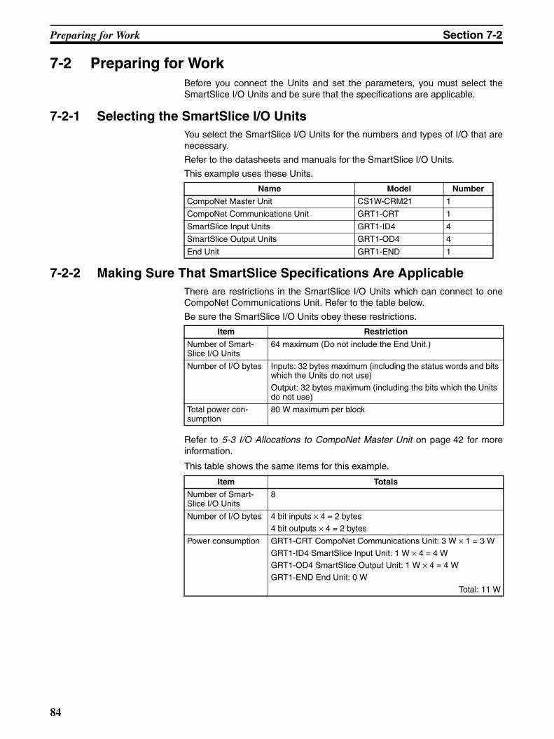
Preparing for Work Section 7-2
7-2 Preparing for WorkBefore you connect the Units and set the parameters, you must select theSmartSlice I/O Units and be sure that the specifications are applicable.
7-2-1 Selecting the SmartSlice I/O UnitsYou select the SmartSlice I/O Units for the numbers and types of I/O that arenecessary.
Refer to the datasheets and manuals for the SmartSlice I/O Units.
This example uses these Units.
7-2-2 Making Sure That SmartSlice Specifications Are ApplicableThere are restrictions in the SmartSlice I/O Units which can connect to oneCompoNet Communications Unit. Refer to the table below.
Be sure the SmartSlice I/O Units obey these restrictions.
Refer to 5-3 I/O Allocations to CompoNet Master Unit on page 42 for moreinformation.
This table shows the same items for this example.
Name Model Number
CompoNet Master Unit CS1W-CRM21 1
CompoNet Communications Unit GRT1-CRT 1
SmartSlice Input Units GRT1-ID4 4
SmartSlice Output Units GRT1-OD4 4
End Unit GRT1-END 1
Item Restriction
Number of Smart-Slice I/O Units
64 maximum (Do not include the End Unit.)
Number of I/O bytes Inputs: 32 bytes maximum (including the status words and bits which the Units do not use)Output: 32 bytes maximum (including the bits which the Units do not use)
Total power con-sumption
80 W maximum per block
Item Totals
Number of Smart-Slice I/O Units
8
Number of I/O bytes 4 bit inputs × 4 = 2 bytes4 bit outputs × 4 = 2 bytes
Power consumption GRT1-CRT CompoNet Communications Unit: 3 W × 1 = 3 W
GRT1-ID4 SmartSlice Input Unit: 1 W × 4 = 4 WGRT1-OD4 SmartSlice Output Unit: 1 W × 4 = 4 WGRT1-END End Unit: 0 W
Total: 11 W
84
Hardware Connections and Settings Section 7-3
7-3 Hardware Connections and SettingsThis section tells you how to install, connect, and set a SmartSlice I/O Termi-nal.
7-3-1 Installing a SmartSlice I/O TerminalYou install a SmartSlice I/O Terminal on DIN Track.
Note Refer to 3-1 Installing a SmartSlice I/O Terminal on page 22 for information onhow to install a SmartSlice I/O Terminal.
7-3-2 Connecting the Communications Cables and Power Cables Use this procedure to connect the SmartSlice I/O Terminal.
1. Connecting the Communications Cables
You connect the communications cable for the CompoNet network to the com-munications connector on the CompoNet Communications Unit.
Note Refer to 4-1 Connecting the Communications Cables on page 30 for the con-nection procedure.
2. Connecting the Unit Power Supply
Connect a 24-VDC power supply for the internal circuits of the CompoNetCommunications Unit and SmartSlice I/O Units to the Unit power supply ter-minals on the CompoNet Communications Unit.
3. Connecting the I/O Power Supply
Connect a 24-VDC power supply for the outputs connected to SmartSliceOutput Units to the I/O power supply terminals on the CompoNet Communica-tions Unit.
Note Refer to 4-2 Connecting the Power Supply Cables on page 31 for the connec-tion procedure.
4. Connecting the External Devices
Connect the I/O signal lines from the external devices (in this example, theswitch and lamp) to the I/O terminals on the SmartSlice I/O Units.
Note Refer to 4-5 Connecting the Signal Lines for External Devices on page 38 forthe connection procedure.
7-3-3 Setting the SmartSlice I/O TerminalsUse this procedure to set the SmartSlice I/O Terminal.
1. Setting the Node Addresses
Set the rotary switches on the CompoNet Communications Unit to the nodeaddress of the SmartSlice I/O Terminal on the CompoNet network.
Note Refer to 5-1 Setting the Node Addresses on page 40 for the setting proce-dure.
• Do not set the same node address for more than one node. • Turn OFF the Unit power supply before you change the node address setting.
Precaution for Correct Usage
85
Hardware Connections and Settings Section 7-3
2. Turning ON the Unit Power Supply
Turn ON pin 1 (REGS) on the DIP switch on the CompoNet CommunicationsUnit, and then turn ON the Unit power supply.
The CompoNet Communications Unit will make a Registration Table showingthe SmartSlice I/O Units which connect to it.
If there was a Registration Table before, the CompoNet Communications Unitwill automatically compare the connected SmartSlice I/O Units with the Regis-tration Table. The TS indicator on the CompoNet Communications Unit willflash in red if there is one or more differences. Communications with allSmartSlice I/O Units will not start.
If the TS indicator flashes in red, turn OFF pin 1, clear the Registration Table,reset the Unit power supply, and turn pin 1 ON again. The CompoNet Com-munications Unit will make a Registration Table for the configuration at thetime.
Note Refer to 6-2 Registration Table on page 54 for more information on the Regis-tration Table.
3. Setting the Functions of the CompoNet Communications Unit
Start the CX-Integrator and set the function of the CompoNet Communica-tions Unit.
If there are no settings to make, go to step 4.
Note Refer to 6-1 Overview of Smart Functions on page 54 for information on thefunctions.
4. Manually Allocating Memory to SmartSlice I/O Units and Setting the Functions
Use the CX-Integrator to manually allocate memory to SmartSlice I/O Units orto set functions.
If there are no settings to make, go to 7-4 Starting Communications on page 87.
Note Refer to the GRT1 Series SmartSlice I/O Units Operation Manual (Cat. No. W455) for more information on SmartSlice I/O Units.
86
Starting Communications Section 7-4
7-4 Starting Communications This section tells you how to make the I/O tables, start the system, and startcommunications.
7-4-1 Making the I/O Tables You must make I/O tables in the CPU Unit of the CompoNet Master Unit. TheI/O tables show the Units in the PLC and their locations.
You use a PLC Programming Device (the CX-Programmer or a ProgrammingConsole) to make the I/O tables.
Refer to the manual for the Master Unit for more information.
7-4-2 Starting the SmartSlice System Turn ON the Unit power supply and I/O power supply to the CompoNet Com-munications Unit.
87
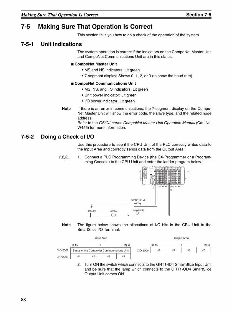
Making Sure That Operation Is Correct Section 7-5
7-5 Making Sure That Operation Is Correct This section tells you how to do a check of the operation of the system.
7-5-1 Unit Indications The system operation is correct if the indicators on the CompoNet Master Unitand CompoNet Communications Unit are in this status.
CompoNet Master Unit
• MS and NS indicators: Lit green
• 7-segment display: Shows 0, 1, 2, or 3 (to show the baud rate)
CompoNet Communications Unit
• MS, NS, and TS indicators: Lit green
• Unit power indicator: Lit green
• I/O power indicator: Lit green
Note If there is an error in communications, the 7-segment display on the Compo-Net Master Unit will show the error code, the slave type, and the related nodeaddress. Refer to the CS/CJ-series CompoNet Master Unit Operation Manual (Cat. No.W456) for more information.
7-5-2 Doing a Check of I/O Use this procedure to see if the CPU Unit of the PLC correctly writes data tothe Input Area and correctly sends data from the Output Area.
1,2,3... 1. Connect a PLC Programming Device (the CX-Programmer or a Program-ming Console) to the CPU Unit and enter the ladder program below.
Note The figure below shows the allocations of I/O bits in the CPU Unit to theSmartSlice I/O Terminal.
2. Turn ON the switch which connects to the GRT1-ID4 SmartSlice Input Unitand be sure that the lamp which connects to the GRT1-OD4 SmartSliceOutput Unit comes ON.
200000200900
#1#2 #3 #4
#5
#6 #7 #8
Switch (bit 0)
Lamp (bit 0)
TS0 12 3
TS0 12 3
OD4 ENDGRT1-CRT
INX OUTX
WORDNODE ADR ×10 ×1
(0-63)
BS
|
BS
BD
HB
D L
DC24VINPUT
TS
UNIT PWR
I/O PWR
MS
NS
ON
1234
REGSI/OADR
BACK
UNIT
I/O
V
V
DC24VINPUT
V
V
ID4TS
0 12 3
ID4TS
0 12 3
ID4TS
0 12 3
ID4
A1
A2
A3
A4
A5
A6 B
6B
5B
4B
3B
2B
1
B6
B5
B4
B3
B2
B1A
1A
2A
3A
4A
5A
6
A1
A2
A3
A4
A5
A6
A1
A2
A3
A4
A5
A6
A1
A2
A3
A4
A5
A6
A1
A2
A3
A4
A5
A6
A1
A2
A3
A4
A5
A6
A1
A2
A3
A4
A5
A6B
6B
5B
4B
3B
2B
1
B6
B5
B4
B3
B2
B1
B6
B5
B4
B3
B2
B1
B6
B5
B4
B3
B2
B1
B6
B5
B4
B3
B2
B1
B6
B5
B4
B3
B2
B1
TS0 12 3
OD4TS
0 12 3
OD4TS
0 12 3
OD4
8
#4 #3 #2 #1
8
#8 #7 #6 #5
Bit 15
Input Area
Bit 0
CIO 2008
CIO 2009
Status of the CompoNet Communications Unit CIO 2000
Output Area
Bit 15 Bit 0
88
SECTION 8Remote I/O Communications
This section tells you about the communications timing for remote I/O communications and message communications. Italso gives more information on communications features.
8-1 Performance of Remote I/O Communications . . . . . . . . . . . . . . . . . . . . . . . . 90
8-1-1 I/O Response Time . . . . . . . . . . . . . . . . . . . . . . . . . . . . . . . . . . . . . . 90
8-2 Performance of Message Communications. . . . . . . . . . . . . . . . . . . . . . . . . . . 93
8-2-1 Message Communications Time. . . . . . . . . . . . . . . . . . . . . . . . . . . . 93
89
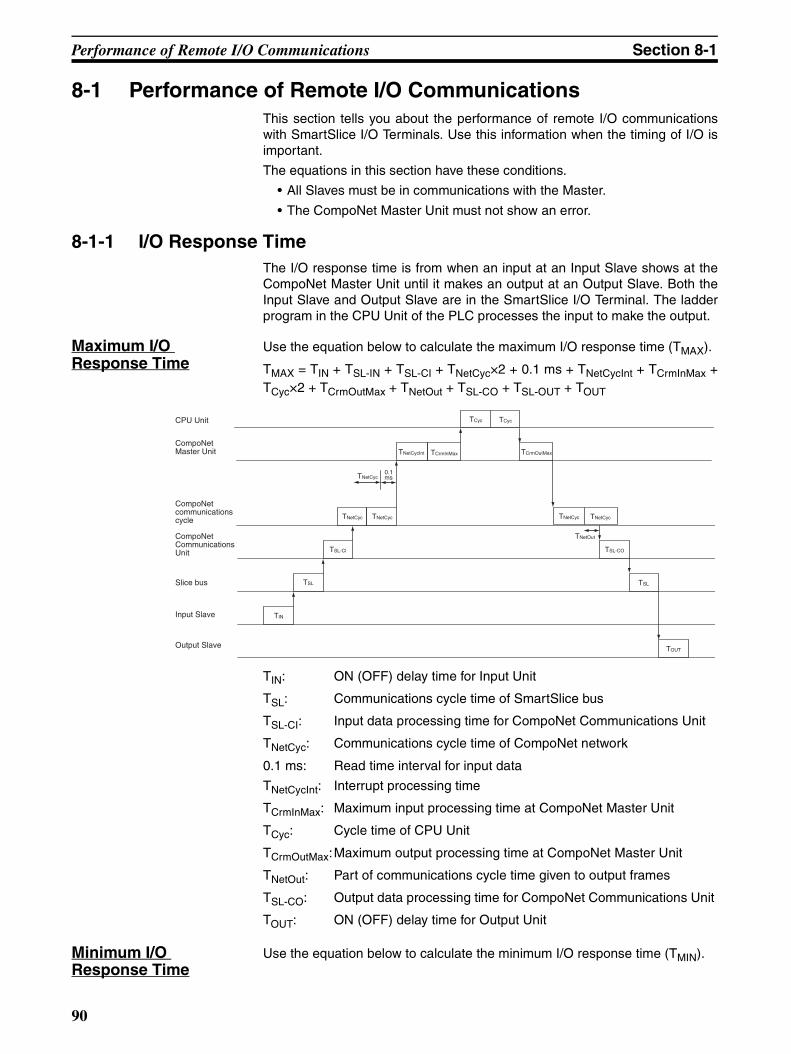
Performance of Remote I/O Communications Section 8-1
8-1 Performance of Remote I/O CommunicationsThis section tells you about the performance of remote I/O communicationswith SmartSlice I/O Terminals. Use this information when the timing of I/O isimportant.
The equations in this section have these conditions.
• All Slaves must be in communications with the Master.
• The CompoNet Master Unit must not show an error.
8-1-1 I/O Response Time The I/O response time is from when an input at an Input Slave shows at theCompoNet Master Unit until it makes an output at an Output Slave. Both theInput Slave and Output Slave are in the SmartSlice I/O Terminal. The ladderprogram in the CPU Unit of the PLC processes the input to make the output.
Maximum I/O Response Time
Use the equation below to calculate the maximum I/O response time (TMAX).
TMAX = TIN + TSL-IN + TSL-CI + TNetCyc×2 + 0.1 ms + TNetCycInt + TCrmInMax +TCyc×2 + TCrmOutMax + TNetOut + TSL-CO + TSL-OUT + TOUT
TIN: ON (OFF) delay time for Input Unit
TSL: Communications cycle time of SmartSlice bus
TSL-CI: Input data processing time for CompoNet Communications Unit
TNetCyc: Communications cycle time of CompoNet network
0.1 ms: Read time interval for input data
TNetCycInt: Interrupt processing time
TCrmInMax: Maximum input processing time at CompoNet Master Unit
TCyc: Cycle time of CPU Unit
TCrmOutMax:Maximum output processing time at CompoNet Master Unit
TNetOut: Part of communications cycle time given to output frames
TSL-CO: Output data processing time for CompoNet Communications Unit
TOUT: ON (OFF) delay time for Output Unit
Minimum I/O Response Time
Use the equation below to calculate the minimum I/O response time (TMIN).
TNetCyc TNetCyc
TNetCyc0.1ms
TNetCycInt TCrmInMax
TNetCyc TNetCyc
TNetOut
TIN
TOUT
TSL TSL
TSL-Cl TSL-CO
TCyc TCyc
TCrmOutMax
CPU Unit
CompoNet communications cycle
CompoNet Communications Unit
Slice bus
Input Slave
Output Slave
CompoNet Master Unit
90
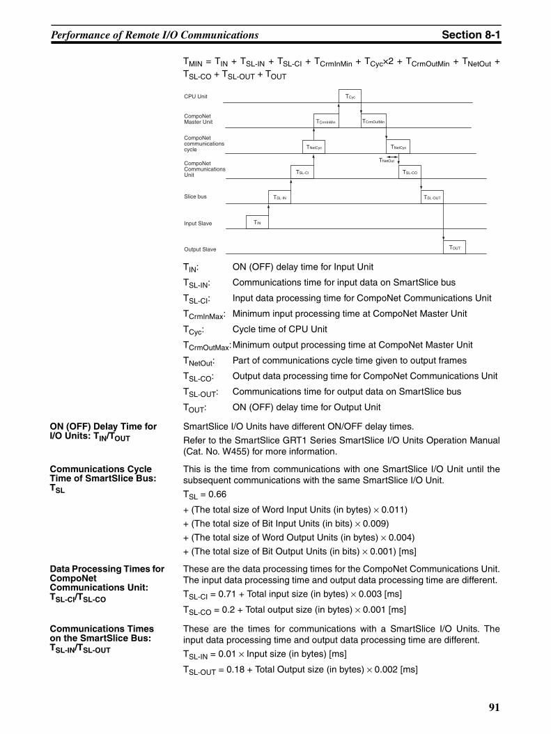
Performance of Remote I/O Communications Section 8-1
TMIN = TIN + TSL-IN + TSL-CI + TCrmInMin + TCyc×2 + TCrmOutMin + TNetOut +TSL-CO + TSL-OUT + TOUT
TIN: ON (OFF) delay time for Input Unit
TSL-IN: Communications time for input data on SmartSlice bus
TSL-CI: Input data processing time for CompoNet Communications Unit
TCrmInMax: Minimum input processing time at CompoNet Master Unit
TCyc: Cycle time of CPU Unit
TCrmOutMax:Minimum output processing time at CompoNet Master Unit
TNetOut: Part of communications cycle time given to output frames
TSL-CO: Output data processing time for CompoNet Communications Unit
TSL-OUT: Communications time for output data on SmartSlice bus
TOUT: ON (OFF) delay time for Output Unit
ON (OFF) Delay Time for I/O Units: TIN/TOUT
SmartSlice I/O Units have different ON/OFF delay times.
Refer to the SmartSlice GRT1 Series SmartSlice I/O Units Operation Manual(Cat. No. W455) for more information.
Communications Cycle Time of SmartSlice Bus: TSL
This is the time from communications with one SmartSlice I/O Unit until thesubsequent communications with the same SmartSlice I/O Unit.
TSL = 0.66
+ (The total size of Word Input Units (in bytes) × 0.011)
+ (The total size of Bit Input Units (in bits) × 0.009)
+ (The total size of Word Output Units (in bytes) × 0.004)
+ (The total size of Bit Output Units (in bits) × 0.001) [ms]
Data Processing Times for CompoNet Communications Unit: TSL-CI/TSL-CO
These are the data processing times for the CompoNet Communications Unit.The input data processing time and output data processing time are different.
TSL-CI = 0.71 + Total input size (in bytes) × 0.003 [ms]
TSL-CO = 0.2 + Total output size (in bytes) × 0.001 [ms]
Communications Times on the SmartSlice Bus: TSL-IN/TSL-OUT
These are the times for communications with a SmartSlice I/O Units. Theinput data processing time and output data processing time are different.
TSL-IN = 0.01 × Input size (in bytes) [ms]
TSL-OUT = 0.18 + Total Output size (in bytes) × 0.002 [ms]
TNetCyc
TCrmInMin
TNetCyc
TNetOut
TIN
TOUT
TSL-IN TSL-OUT
TSL-Cl TSL-CO
TCyc
TCrmOutMin
CPU Unit
CompoNet communications cycle
CompoNet Communications Unit
Slice bus
Input Slave
Output Slave
CompoNet Master Unit
91

Performance of Remote I/O Communications Section 8-1
Note Refer to the CS/CJ-series CompoNet Master Unit Operation Manual (Cat. No.W456) for information on these variables: Communications cycle time of Com-poNet network (TNetCyc), interrupt processing time (TNetCycInt), maximum/min-imum input processing time at CompoNet Master Unit (TCrmlnMax/TCrmlnMin),cycle time of the CPU Unit (TCyc), maximum/minimum output processing timeat Master (TCrmOutMax/TCrmOutMin), part of communications cycle time given tooutput frames (TNetOut).
92
Performance of Message Communications Section 8-2
8-2 Performance of Message Communications This section tells you about the performance of message communicationsbetween the CompoNet network and a SmartSlice I/O Terminal.
8-2-1 Message Communications Time The message communications time is the time from starting to send a mes-sage on the CompoNet network until the SmartSlice I/O Terminal receives themessage. You send data messages with the SEND instruction and receivedata messages with the RECV instruction. You send FINS command mes-sages with the CMND instruction.
Message Communications Time to the CompoNet Communications UnitUse the following equation to get an estimate of the message communicationstime to the CompoNet Communications Unit.
Message communications time = Communications cycle time of CompoNetnetwork (TNetCyc) × (Number of message bytes + 15) ÷ 6 + 1
The number of message bytes includes all bytes for the destination nodeaddress, service code, class ID, instance ID, attribute ID, and service data.Refer to the CS/CJ-series CompoNet Master Unit Operation Manual (Cat. No.W456) for information on this variable: Communications cycle time of Compo-Net network (TNetCyc).
Message Communications Time to the SmartSlice I/O UnitWhen you send a message to a SmartSlice I/O Unit, you must add the mes-sage communications time on the SmartSlice bus to the message communi-cations time to the CompoNet Communications Unit.
Use the following equation to get an estimate of the message communicationstime on the SmartSlice bus.
Message communications time = TSL × Number of frames
Number of frames = Number of message bytes ÷ 30 (Round up decimal dig-its.)
Note (1) When using message communications, execute the communications in-structions (SEND, RECV, and CMND) at intervals longer than the mes-sage communications time. If a message that was sent or received is lost,the CompoNet Master Unit will record an error in the error history. You canread the error history with the CX-Integrator or FINS commands.
(2) This message communications time is an estimate. It is not the maximumvalue. The frequency of messages, the load on the remote node, thecommunications cycle time, and other factors have an effect on the mes-sage communications time. The message communications time can belonger than the value you calculate here if there is a high load on theCompoNet Master Unit.
93

Performance of Message Communications Section 8-2
94
SECTION 9Error Procedures
This section tells you how to troubleshoot problems that you can have with the CompoNet Communications Unit andSmartSlice I/O Units. It also tells how to see the error history with the CX-Integrator.
9-1 Error Procedures with Indicators . . . . . . . . . . . . . . . . . . . . . . . . . . . . . . . . . . 96
9-1-1 CompoNet Communications Unit . . . . . . . . . . . . . . . . . . . . . . . . . . 96
9-1-2 SmartSlice I/O Units. . . . . . . . . . . . . . . . . . . . . . . . . . . . . . . . . . . . . 99
9-1-3 I/O Power Feed Units . . . . . . . . . . . . . . . . . . . . . . . . . . . . . . . . . . . . 99
9-1-4 Left Turnback Units . . . . . . . . . . . . . . . . . . . . . . . . . . . . . . . . . . . . . 99
9-2 Error Procedures with CX-Integrator . . . . . . . . . . . . . . . . . . . . . . . . . . . . . . . 100
9-2-1 Communications Errors on CompoNet Networks . . . . . . . . . . . . . . 100
9-2-2 Communications Status of SmartSlice Bus . . . . . . . . . . . . . . . . . . . 101
9-2-3 Errors in SmartSlice I/O Terminals . . . . . . . . . . . . . . . . . . . . . . . . . 102
9-3 Other Error Causes and Error Procedures. . . . . . . . . . . . . . . . . . . . . . . . . . . . 105
95
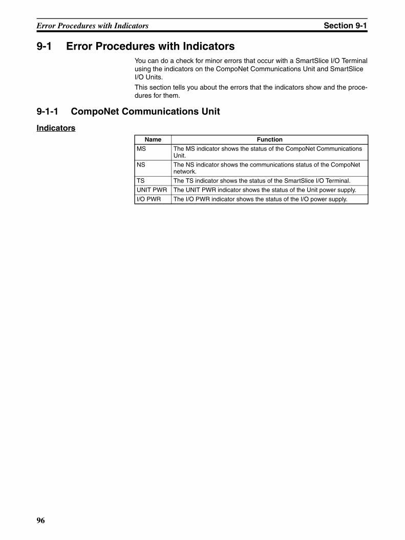
Error Procedures with Indicators Section 9-1
9-1 Error Procedures with IndicatorsYou can do a check for minor errors that occur with a SmartSlice I/O Terminalusing the indicators on the CompoNet Communications Unit and SmartSlice I/O Units.
This section tells you about the errors that the indicators show and the proce-dures for them.
9-1-1 CompoNet Communications Unit
IndicatorsName Function
MS The MS indicator shows the status of the CompoNet Communications Unit.
NS The NS indicator shows the communications status of the CompoNet network.
TS The TS indicator shows the status of the SmartSlice I/O Terminal.
UNIT PWR The UNIT PWR indicator shows the status of the Unit power supply.
I/O PWR The I/O PWR indicator shows the status of the I/O power supply.
96
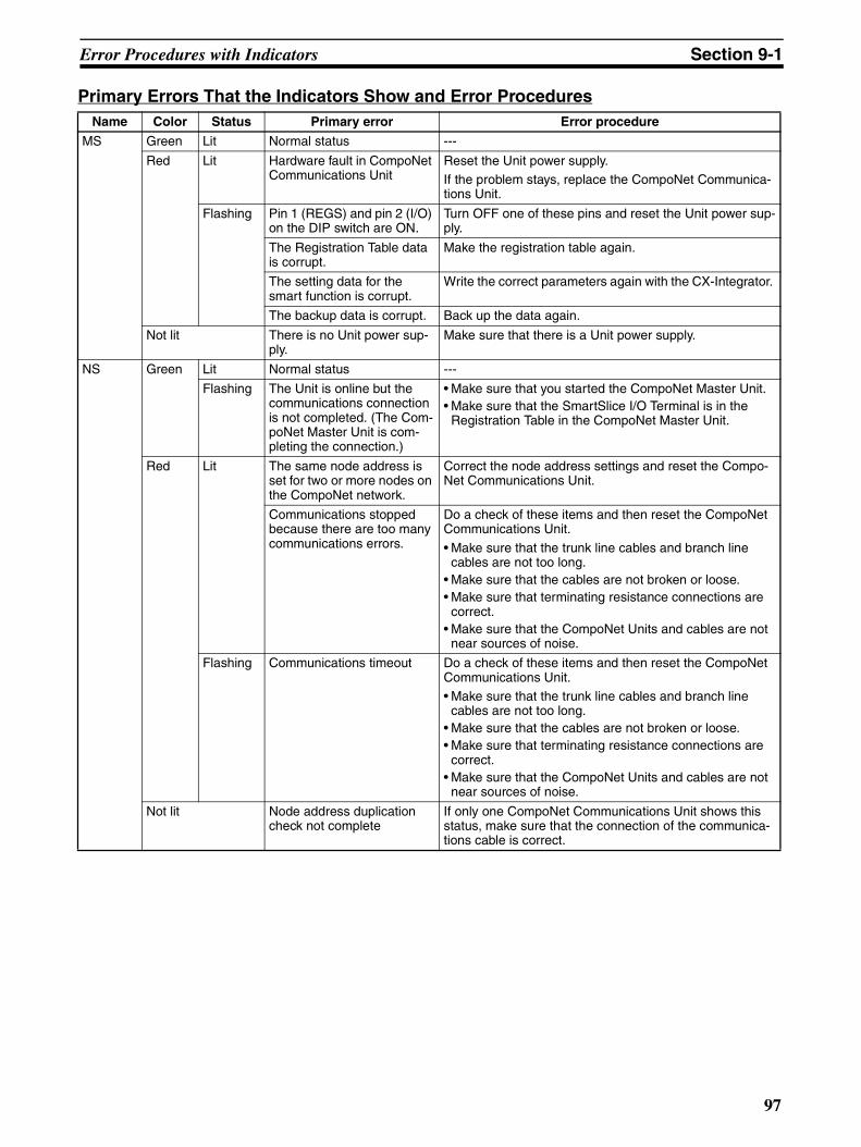
Error Procedures with Indicators Section 9-1
Primary Errors That the Indicators Show and Error ProceduresName Color Status Primary error Error procedure
MS Green Lit Normal status ---
Red Lit Hardware fault in CompoNet Communications Unit
Reset the Unit power supply. If the problem stays, replace the CompoNet Communica-tions Unit.
Flashing Pin 1 (REGS) and pin 2 (I/O) on the DIP switch are ON.
Turn OFF one of these pins and reset the Unit power sup-ply.
The Registration Table data is corrupt.
Make the registration table again.
The setting data for the smart function is corrupt.
Write the correct parameters again with the CX-Integrator.
The backup data is corrupt. Back up the data again.
Not lit There is no Unit power sup-ply.
Make sure that there is a Unit power supply.
NS Green Lit Normal status ---
Flashing The Unit is online but the communications connection is not completed. (The Com-poNet Master Unit is com-pleting the connection.)
• Make sure that you started the CompoNet Master Unit. • Make sure that the SmartSlice I/O Terminal is in the
Registration Table in the CompoNet Master Unit.
Red Lit The same node address is set for two or more nodes on the CompoNet network.
Correct the node address settings and reset the Compo-Net Communications Unit.
Communications stopped because there are too many communications errors.
Do a check of these items and then reset the CompoNet Communications Unit.
• Make sure that the trunk line cables and branch line cables are not too long.
• Make sure that the cables are not broken or loose. • Make sure that terminating resistance connections are
correct. • Make sure that the CompoNet Units and cables are not
near sources of noise.
Flashing Communications timeout Do a check of these items and then reset the CompoNet Communications Unit. • Make sure that the trunk line cables and branch line
cables are not too long. • Make sure that the cables are not broken or loose. • Make sure that terminating resistance connections are
correct. • Make sure that the CompoNet Units and cables are not
near sources of noise.
Not lit Node address duplication check not complete
If only one CompoNet Communications Unit shows this status, make sure that the connection of the communica-tions cable is correct.
97
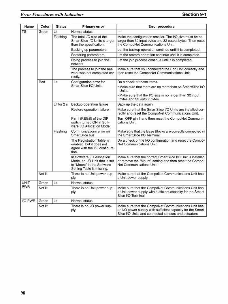
Error Procedures with Indicators Section 9-1
TS Green Lit Normal status ---
Flashing The total I/O size of the SmartSlice I/O Units is larger than the specification.
Make the configuration smaller. The I/O size must be no larger than 32 input bytes and 32 output bytes. Then reset the CompoNet Communications Unit.
Backing up parameters Let the backup operation continue until it is completed.
Restoring parameters Let the restore operation continue until it is completed.
Doing process to join the network
Let the join process continue until it is completed.
The process to join the net-work was not completed cor-rectly.
Make sure that you connected the End Unit correctly and then reset the CompoNet Communications Unit.
Red Lit Configuration error for SmartSlice I/O Units
Do a check of these items. • Make sure that there are no more than 64 SmartSlice I/O
Units. • Make sure that the I/O size is no larger than 32 input
bytes and 32 output bytes.
Lit for 2 s Backup operation failure Back up the data again.
Restore operation failure Make sure that the SmartSlice I/O Units are installed cor-rectly and reset the CompoNet Communications Unit.
Pin 1 (REGS) of the DIP switch turned ON in Soft-ware I/O Allocation Mode.
Turn OFF pin 1 and then reset the CompoNet Communi-cations Unit.
Flashing Communications error on SmartSlice bus
Make sure that the Base Blocks are correctly connected in the SmartSlice I/O Terminal.
The Registration Table is enabled, but it does not agree with the I/O configura-tion.
Do a check of the I/O configuration and reset the Compo-Net Communications Unit.
In Software I/O Allocation Mode, an I/O Unit that is set to “Mount” in the Software Setting Table is missing.
Make sure that the correct SmartSlice I/O Unit is installed or remove the “Mount” setting and then reset the Compo-Net Communications Unit.
Not lit There is no Unit power sup-ply.
Make sure that the CompoNet Communications Unit has a Unit power supply.
UNIT PWR
Green Lit Normal status ---
Not lit There is no Unit power sup-ply.
Make sure that the CompoNet Communications Unit has a Unit power supply with sufficient capacity for the Smart-Slice I/O Terminal.
I/O PWR Green Lit Normal status ---
Not lit There is no I/O power sup-ply.
Make sure that the CompoNet Communications Unit has an I/O power supply with sufficient capacity for the Smart-Slice I/O Units and connected sensors and actuators.
Name Color Status Primary error Error procedure
98
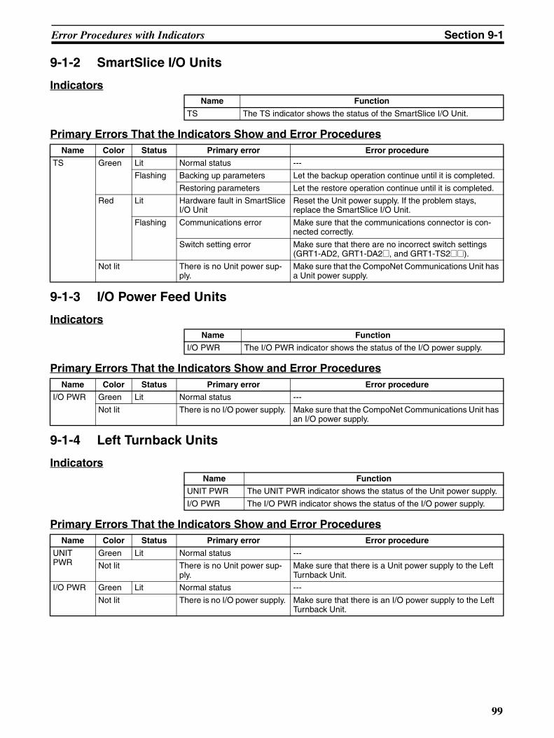
Error Procedures with Indicators Section 9-1
9-1-2 SmartSlice I/O Units
Indicators
Primary Errors That the Indicators Show and Error Procedures
9-1-3 I/O Power Feed Units
Indicators
Primary Errors That the Indicators Show and Error Procedures
9-1-4 Left Turnback Units
Indicators
Primary Errors That the Indicators Show and Error Procedures
Name Function
TS The TS indicator shows the status of the SmartSlice I/O Unit.
Name Color Status Primary error Error procedure
TS Green Lit Normal status ---
Flashing Backing up parameters Let the backup operation continue until it is completed.
Restoring parameters Let the restore operation continue until it is completed.
Red Lit Hardware fault in SmartSlice I/O Unit
Reset the Unit power supply. If the problem stays, replace the SmartSlice I/O Unit.
Flashing Communications error Make sure that the communications connector is con-nected correctly.
Switch setting error Make sure that there are no incorrect switch settings (GRT1-AD2, GRT1-DA2@, and GRT1-TS2@@).
Not lit There is no Unit power sup-ply.
Make sure that the CompoNet Communications Unit has a Unit power supply.
Name Function
I/O PWR The I/O PWR indicator shows the status of the I/O power supply.
Name Color Status Primary error Error procedure
I/O PWR Green Lit Normal status ---
Not lit There is no I/O power supply. Make sure that the CompoNet Communications Unit has an I/O power supply.
Name Function
UNIT PWR The UNIT PWR indicator shows the status of the Unit power supply.
I/O PWR The I/O PWR indicator shows the status of the I/O power supply.
Name Color Status Primary error Error procedure
UNIT PWR
Green Lit Normal status ---
Not lit There is no Unit power sup-ply.
Make sure that there is a Unit power supply to the Left Turnback Unit.
I/O PWR Green Lit Normal status ---
Not lit There is no I/O power supply. Make sure that there is an I/O power supply to the Left Turnback Unit.
99
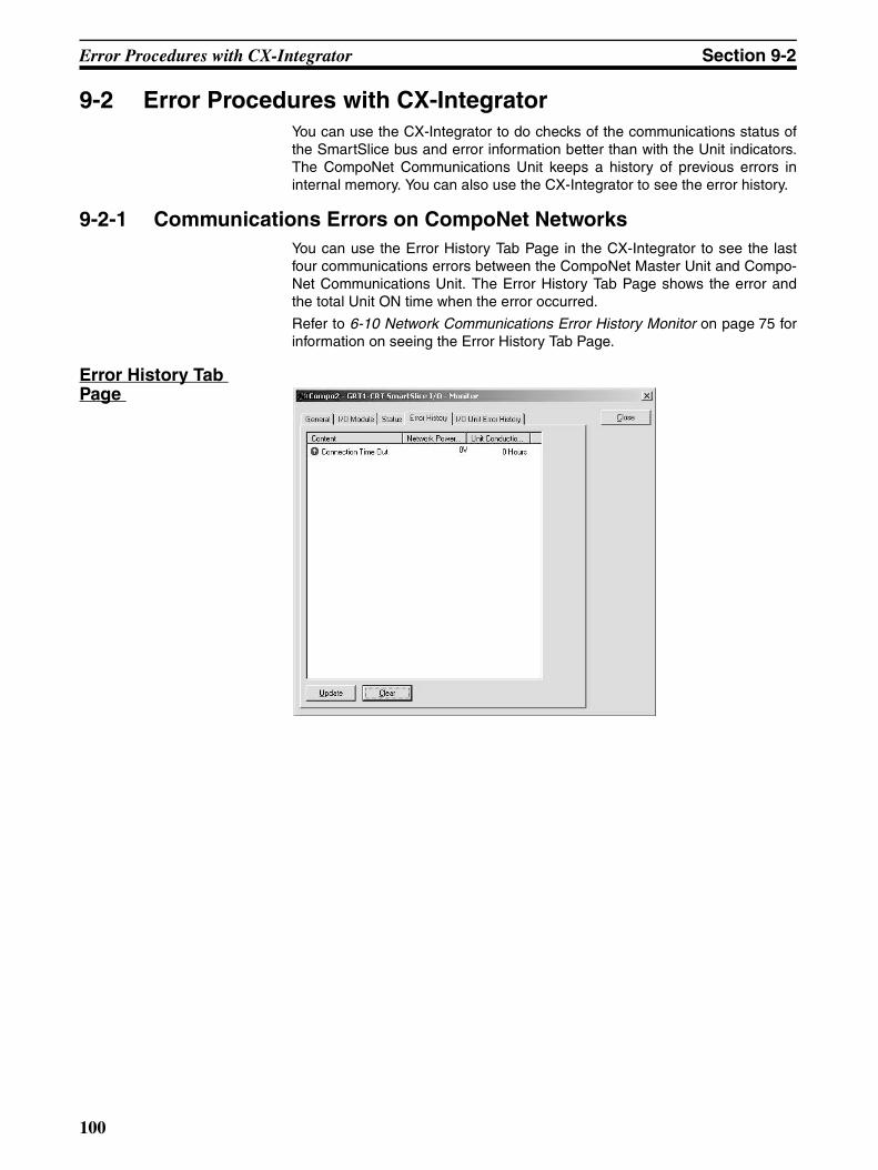
Error Procedures with CX-Integrator Section 9-2
9-2 Error Procedures with CX-IntegratorYou can use the CX-Integrator to do checks of the communications status ofthe SmartSlice bus and error information better than with the Unit indicators.The CompoNet Communications Unit keeps a history of previous errors ininternal memory. You can also use the CX-Integrator to see the error history.
9-2-1 Communications Errors on CompoNet NetworksYou can use the Error History Tab Page in the CX-Integrator to see the lastfour communications errors between the CompoNet Master Unit and Compo-Net Communications Unit. The Error History Tab Page shows the error andthe total Unit ON time when the error occurred.
Refer to 6-10 Network Communications Error History Monitor on page 75 forinformation on seeing the Error History Tab Page.
Error History Tab Page
100
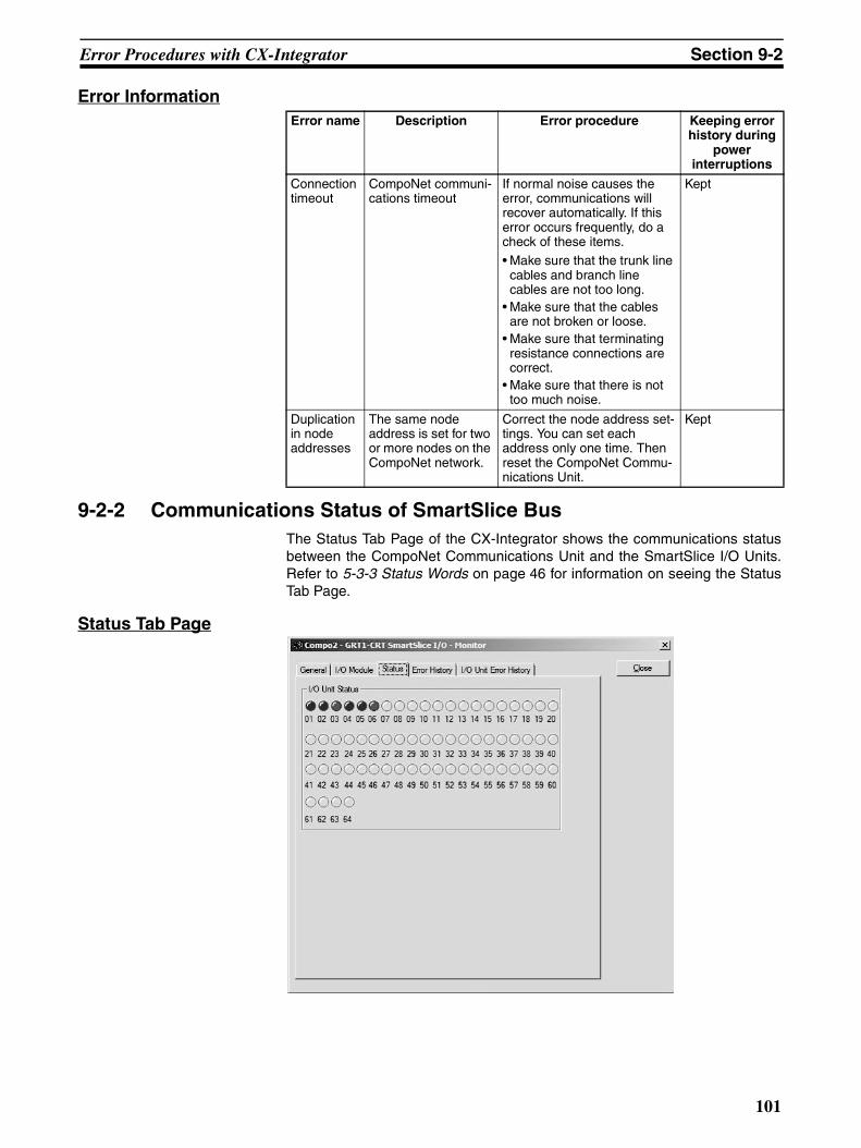
Error Procedures with CX-Integrator Section 9-2
Error Information
9-2-2 Communications Status of SmartSlice BusThe Status Tab Page of the CX-Integrator shows the communications statusbetween the CompoNet Communications Unit and the SmartSlice I/O Units.Refer to 5-3-3 Status Words on page 46 for information on seeing the StatusTab Page.
Status Tab Page
Error name Description Error procedure Keeping error history during
power interruptions
Connection timeout
CompoNet communi-cations timeout
If normal noise causes the error, communications will recover automatically. If this error occurs frequently, do a check of these items. • Make sure that the trunk line
cables and branch line cables are not too long.
• Make sure that the cables are not broken or loose.
• Make sure that terminating resistance connections are correct.
• Make sure that there is not too much noise.
Kept
Duplication in node addresses
The same node address is set for two or more nodes on the CompoNet network.
Correct the node address set-tings. You can set each address only one time. Then reset the CompoNet Commu-nications Unit.
Kept
101
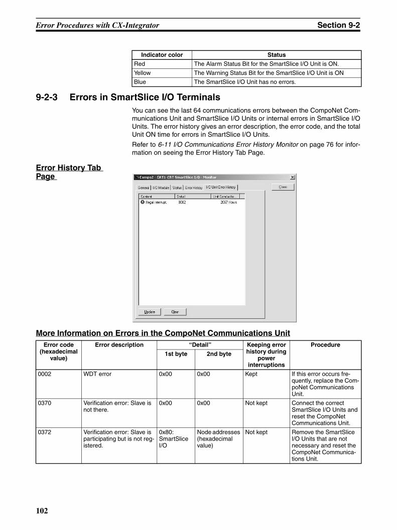
Error Procedures with CX-Integrator Section 9-2
9-2-3 Errors in SmartSlice I/O TerminalsYou can see the last 64 communications errors between the CompoNet Com-munications Unit and SmartSlice I/O Units or internal errors in SmartSlice I/OUnits. The error history gives an error description, the error code, and the totalUnit ON time for errors in SmartSlice I/O Units.
Refer to 6-11 I/O Communications Error History Monitor on page 76 for infor-mation on seeing the Error History Tab Page.
Error History Tab Page
More Information on Errors in the CompoNet Communications Unit
Indicator color Status
Red The Alarm Status Bit for the SmartSlice I/O Unit is ON.
Yellow The Warning Status Bit for the SmartSlice I/O Unit is ON
Blue The SmartSlice I/O Unit has no errors.
Error code (hexadecimal
value)
Error description “Detail” Keeping error history during
power interruptions
Procedure
1st byte 2nd byte
0002 WDT error 0x00 0x00 Kept If this error occurs fre-quently, replace the Com-poNet Communications Unit.
0370 Verification error: Slave is not there.
0x00 0x00 Not kept Connect the correct SmartSlice I/O Units and reset the CompoNet Communications Unit.
0372 Verification error: Slave is participating but is not reg-istered.
0x80:SmartSlice I/O
Node addresses (hexadecimal value)
Not kept Remove the SmartSlice I/O Units that are not necessary and reset the CompoNet Communica-tions Unit.
102
Error Procedures with CX-Integrator Section 9-2
021A Logic error in table settingsCause
There is a checksum error or invalid setting in one of these tables.
• Registration Table• Slave parameters • Network parameters • Backup/restore data
0x00 0x0A: Registra-tion Table
0x0B: Slave parameters 0x0C: Network parameters 0x0F: Backup/restore data
Kept Download the settings again.
0602 Memory access error
Cause• There is a hardware fault
in the nonvolatile memory element in the Unit.
• ADR failed (communica-tions failed)
0x01: Read error0x02: Write error
0x07: Error his-tory 0x09: Identity information
0x0A: Registra-tion Table 0x0C: Network parameters 0x0F: Backup/restore data
Kept (Not kept in error history)
If this error occurs fre-quently, replace the Com-poNet Communications Unit.
Error code (hexadecimal
value)
Error description “Detail” Keeping error history during
power interruptions
Procedure
1st byte 2nd byte
103
Error Procedures with CX-Integrator Section 9-2
More Information on Errors in SmartSlice I/O UnitsError code
(hexadecimal value)
Error description “Detail” Keeping error history during
power interruptions
Procedure
1st byte 2nd byte
0300 Reception error for backup data
0x80: SmartSlice I/O
Node addresses (hexadecimal value)
Not kept • Make sure that the SmartSlice I/O Units are correctly connected.
• Make sure that there are no sources of noise near the Unit.
0374 Transmission error Cause
A transmission error occurred.
0x80: SmartSlice I/O
Node addresses (hexadecimal value)
Not kept • Make sure that the SmartSlice I/O Units are correctly connected.
• Make sure that there are no sources of noise near the Unit.
0375 Communications stopped because of a transmission error
Cause A transmission error occurred when the Unit was set to stop communi-cations for transmission errors.
0x80: SmartSlice I/O
Node addresses (hexadecimal value)
Kept • Make sure that the SmartSlice I/O Units are correctly connected.
• Make sure that there are no sources of noise near the Unit.
0376 Slave duplication error Cause
A Slave duplication error occurred.
0x80: SmartSlice I/O
Node addresses (hexadecimal value)
Not kept Make sure that the SmartSlice I/O Units are connected correctly and then reset the Compo-Net Communications Unit.
0378 I/O size error 0x00 0x00 Not kept Make sure that the SmartSlice I/O Units are connected correctly and then reset the Compo-Net Communications Unit.
0379 SmartSlice configuration error
0x00 0x00 Not kept Make sure that the SmartSlice I/O Units are connected correctly and then reset the Compo-Net Communications Unit.
104
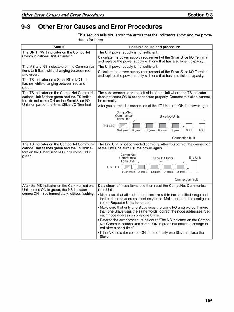
Other Error Causes and Error Procedures Section 9-3
9-3 Other Error Causes and Error Procedures This section tells you about the errors that the indicators show and the proce-dures for them.
Status Possible cause and procedure
The UNIT PWR indicator on the CompoNet Communications Unit is flashing.
The Unit power supply is not sufficient.Calculate the power supply requirement of the SmartSlice I/O Terminal and replace the power supply with one that has a sufficient capacity.
The MS and NS indicators on the Communica-tions Unit flash while changing between red and green.The TS indicator on a SmartSlice I/O Unit flashes while changing between red and green.
The Unit power supply is not sufficient.
Calculate the power supply requirement of the SmartSlice I/O Terminal and replace the power supply with one that has a sufficient capacity.
The TS indicator on the CompoNet Communi-cations Unit flashes green and the TS indica-tors do not come ON on the SmartSlice I/O Units on part of the SmartSlice I/O Terminal.
The slide connector on the left side of the Unit where the TS indicator does not come ON is not connected properly. Connect this slide connec-tor correctly.After you correct the connection of the I/O Unit, turn ON the power again.
The TS indicator on the CompoNet Communi-cations Unit flashes green and the TS indica-tors on the SmartSlice I/O Units come ON in green.
The End Unit is not connected correctly. After you correct the connection of the End Unit, turn ON the power again.
After the MS indicator on the Communications Unit comes ON in green, the NS indicator comes ON in red immediately, without flashing.
Do a check of these items and then reset the CompoNet Communica-tions Unit. • Make sure that all node addresses are within the specified range and
that each node address is set only once. Make sure that the configura-tion of Repeater Units is correct.
• Make sure that only one Slave uses the same I/O area words. If more than one Slave uses the same words, correct the node addresses. Set each node address on only one Slave.
• Refer to the error procedure below at “The NS indicator on the Compo-Net Communications Unit comes ON in green but makes a change to red after a short time.”
• If the NS indicator comes ON in red on only one Slave, replace the Slave.
[TS] LED
CompoNet Communica-
tions Unit Slice I/O Units
Flash green. Lit green. Lit green. Lit green. Lit green.
Connection fault
Not lit.Not lit.
[TS] LED
CompoNet Communica-
tions Unit Slice I/O Units
Flash green. Lit green. Lit green. Lit green. Lit green.
Connection fault
End Unit
105
Other Error Causes and Error Procedures Section 9-3
The NS indicator on the CompoNet Communi-cations Unit comes ON in green but makes a change to red after a short time.ORThe NS indicator on the CompoNet Communi-cations Unit comes ON in green but flashes red after a short time.
Do a check of these items and then reset the CompoNet Communica-tions Unit.
• Make sure that there is terminating resistance of 121 Ω at each end of the trunk line of the network. If terminating resistance is not connected, connect 121 Ω.
• Make sure that the settings for all Slaves are correct. • Make sure that the connections of the communications cables are cor-
rect. • Make sure that the connections and settings of the power supply cables
are correct. • Make sure that there are no disconnections in the connections to the
connectors for the communications cables and power supply cables at all nodes.
• If there are sources of noise in the area, do noise countermeasures for the Master Unit, Slaves, and communications cables.
• If you are using an OMRON Master Unit and there is an error in the Master Unit, refer to the CS/CJ-series CompoNet Master Unit Opera-tion Manual (Cat. No. W456). If you are using a Master Unit from a dif-ferent company, refer to the operation manual for the Master Unit.
• If the NS indicator comes ON in red on only one CompoNet Communi-cations Unit, replace the Unit.
The NS indicator on the CompoNet Communi-cations Unit goes OFF and stays OFF.
Do a check of these items and then reset the CompoNet Communica-tions Unit.
• Make sure that the operation of the CompoNet Master Unit is correct. If you are using an OMRON Master Unit, make sure the operating mode and slave node addresses are correct. If you are using a Master Unit from a different company, refer to the operation manual for the Master Unit.
• Make sure that the connections of the connectors for all Slaves are cor-rect.
• Make sure that the operation of the CompoNet Master Unit is correct. If you are using an OMRON Master Unit, refer to the CS/CJ-series Com-poNet Master Unit Operation Manual (Cat. No. W456). If you are using a Master Unit from a different company, refer to the operation manual for the Master Unit.
• Make sure that the connections of the communications cables are cor-rect.
• Make sure that the connections and settings of the power supply cables are correct.
• Make sure that there are no disconnections in the connections to the connectors for the communications cables and power supply cables.
The NS indicator on the CompoNet Communi-cations Unit continues to flash.
• Make sure that the operation of the CompoNet Master Unit is correct. If you are using an OMRON Master Unit, make sure the operating mode and slave node addresses are correct. If you are using a Master Unit from a different company, refer to the operation manual for the Master Unit.
• Make sure that the Slave is in the Registration Table in the Master Unit. If you are using an OMRON Master Unit, a new Slave will not join the network if you add it when the Master Unit is operating with the Regis-tration Table. Clear the Registration Table, make sure that the new Slave is in the net-work, and then create the Registration Table. If you are using a Master Unit from a different company, refer to the operation manual for the Master Unit for information on using the Regis-tration Table.
• Make sure that the I/O areas of the Slaves are not more than the per-mitted area for the Master Unit. If it is necessary, correct the node addresses.
Status Possible cause and procedure
106
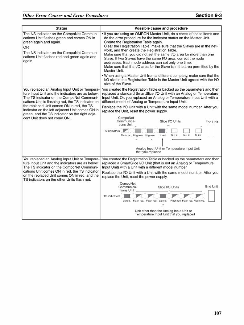
Other Error Causes and Error Procedures Section 9-3
The NS indicator on the CompoNet Communi-cations Unit flashes green and comes ON in green again and again. ORThe NS indicator on the CompoNet Communi-cations Unit flashes red and green again and again.
• If you are using an OMRON Master Unit, do a check of these items and do the error procedure for the indicator status on the Master Unit. Create the Registration Table again. Clear the Registration Table, make sure that the Slaves are in the net-work, and then create the Registration Table. Make sure that you did not set the same I/O area for more than one Slave. If two Slaves have the same I/O area, correct the node addresses. Each node address can set only one time. Make sure that the I/O area for the Slave is in the area permitted by the Master Unit.
• When using a Master Unit from a different company, make sure that the I/O size in the Registration Table in the Master Unit agrees with the I/O size of the Slave.
You replaced an Analog Input Unit or Tempera-ture Input Unit and the indicators are as below: The TS indicator on the CompoNet Communi-cations Unit is flashing red, the TS indicator on the replaced Unit comes ON in red, the TS indicator on the left adjacent Unit comes ON in green, and the TS indicator on the right adja-cent Unit does not come ON.
You created the Registration Table or backed up the parameters and then replaced a standard SmartSlice I/O Unit with an Analog or Temperature Input Unit. Or, you replaced an Analog or Temperature Input Unit with a different model of Analog or Temperature Input Unit.
Replace the I/O Unit with a Unit with the same model number. After you replace the Unit, reset the power supply.
You replaced an Analog Input Unit or Tempera-ture Input Unit and the indicators are as below: The TS indicator on the CompoNet Communi-cations Unit comes ON in red, the TS indicator on the replaced Unit comes ON in red, and the TS indicators on the other Units flash red.
You created the Registration Table or backed up the parameters and then replaced a SmartSlice I/O Unit (that is not an Analog or Temperature Input Unit) with a Unit with a different model number.
Replace the I/O Unit with a Unit with the same model number. After you replace the Unit, reset the power supply.
Status Possible cause and procedure
TS indicators
CompoNet Communica-
tions Unit Slice I/O Units
Flash red. Lit green. Lit green. Lit red. Not lit. Not lit.Not lit.
End Unit
Analog Input Unit or Temperature Input Unit that you replaced
TS indicators
CompoNet Communica-
tions Unit Slice I/O Units
Lit red. Flash red. Flash red. Lit red. Flash red. Flash red.Flash red.
End Unit
Unit other than the Analog Input Unit or Temperature Input Unit that you replaced
107

Other Error Causes and Error Procedures Section 9-3
108
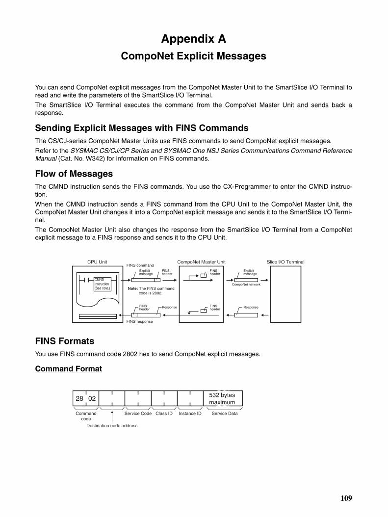
Appendix ACompoNet Explicit Messages
You can send CompoNet explicit messages from the CompoNet Master Unit to the SmartSlice I/O Terminal toread and write the parameters of the SmartSlice I/O Terminal.
The SmartSlice I/O Terminal executes the command from the CompoNet Master Unit and sends back aresponse.
Sending Explicit Messages with FINS CommandsThe CS/CJ-series CompoNet Master Units use FINS commands to send CompoNet explicit messages.
Refer to the SYSMAC CS/CJ/CP Series and SYSMAC One NSJ Series Communications Command ReferenceManual (Cat. No. W342) for information on FINS commands.
Flow of MessagesThe CMND instruction sends the FINS commands. You use the CX-Programmer to enter the CMND instruc-tion.
When the CMND instruction sends a FINS command from the CPU Unit to the CompoNet Master Unit, theCompoNet Master Unit changes it into a CompoNet explicit message and sends it to the SmartSlice I/O Termi-nal.
The CompoNet Master Unit also changes the response from the SmartSlice I/O Terminal from a CompoNetexplicit message to a FINS response and sends it to the CPU Unit.
FINS FormatsYou use FINS command code 2802 hex to send CompoNet explicit messages.
Command Format
Slice I/O TerminalCompoNet Master UnitCPU UnitFINS command
Explicitmessage
Note: The FINS command code is 2802.
Explicitmessage
FINSheader
FINSheader
FINSheader
FINSheader
Response Response
CompoNet network
FINS response
CMNDinstruction(See note.)
28 02
Commandcode
Destination node address
Service Code Class ID Instance ID
532 bytes maximum
Service Data
109
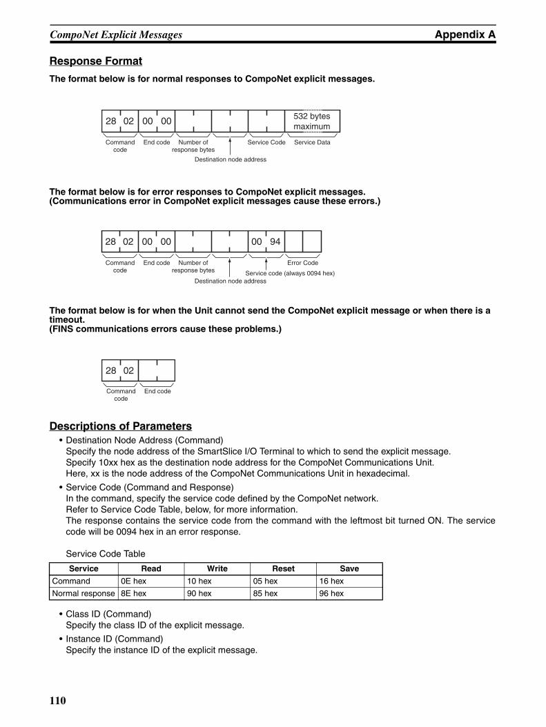
CompoNet Explicit Messages Appendix A
Response Format
The format below is for normal responses to CompoNet explicit messages.
The format below is for error responses to CompoNet explicit messages. (Communications error in CompoNet explicit messages cause these errors.)
The format below is for when the Unit cannot send the CompoNet explicit message or when there is a timeout. (FINS communications errors cause these problems.)
Descriptions of Parameters• Destination Node Address (Command)
Specify the node address of the SmartSlice I/O Terminal to which to send the explicit message. Specify 10xx hex as the destination node address for the CompoNet Communications Unit. Here, xx is the node address of the CompoNet Communications Unit in hexadecimal.
• Service Code (Command and Response)In the command, specify the service code defined by the CompoNet network. Refer to Service Code Table, below, for more information. The response contains the service code from the command with the leftmost bit turned ON. The servicecode will be 0094 hex in an error response.
Service Code Table
• Class ID (Command) Specify the class ID of the explicit message.
• Instance ID (Command) Specify the instance ID of the explicit message.
Service Read Write Reset Save
Command 0E hex 10 hex 05 hex 16 hex
Normal response 8E hex 90 hex 85 hex 96 hex
28 02 00 00 532 bytesmaximum
Commandcode
End code
Destination node address
Number ofresponse bytes
Service Code Service Data
28 02 00 00 00 94
Service code (always 0094 hex)
Error CodeCommandcode
End code
Destination node address
Number ofresponse bytes
28 02
Commandcode
End code
110
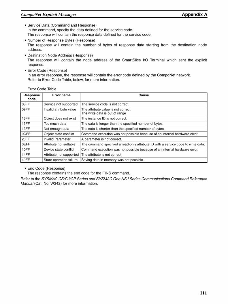
CompoNet Explicit Messages Appendix A
• Service Data (Command and Response) In the command, specify the data defined for the service code. The response will contain the response data defined for the service code.
• Number of Response Bytes (Response) The response will contain the number of bytes of response data starting from the destination nodeaddress.
• Destination Node Address (Response) The response will contain the node address of the SmartSlice I/O Terminal which sent the explicitresponse.
• Error Code (Response) In an error response, the response will contain the error code defined by the CompoNet network. Refer to Error Code Table, below, for more information.
Error Code Table
• End Code (Response) The response contains the end code for the FINS command.
Refer to the SYSMAC CS/CJ/CP Series and SYSMAC One NSJ Series Communications Command ReferenceManual (Cat. No. W342) for more information.
Response code
Error name Cause
08FF Service not supported The service code is not correct.
09FF Invalid attribute value The attribute value is not correct. The write data is out of range
16FF Object does not exist The instance ID is not correct.
15FF Too much data The data is longer than the specified number of bytes.
13FF Not enough data The data is shorter than the specified number of bytes.
0CFF Object state conflict Command execution was not possible because of an internal hardware error.
20FF Invalid Parameter A parameter is not correct.
0EFF Attribute not settable The command specified a read-only attribute ID with a service code to write data.
10FF Device state conflict Command execution was not possible because of an internal hardware error.
14FF Attribute not supported The attribute is not correct.
19FF Store operation failure Saving data in memory was not possible.
111
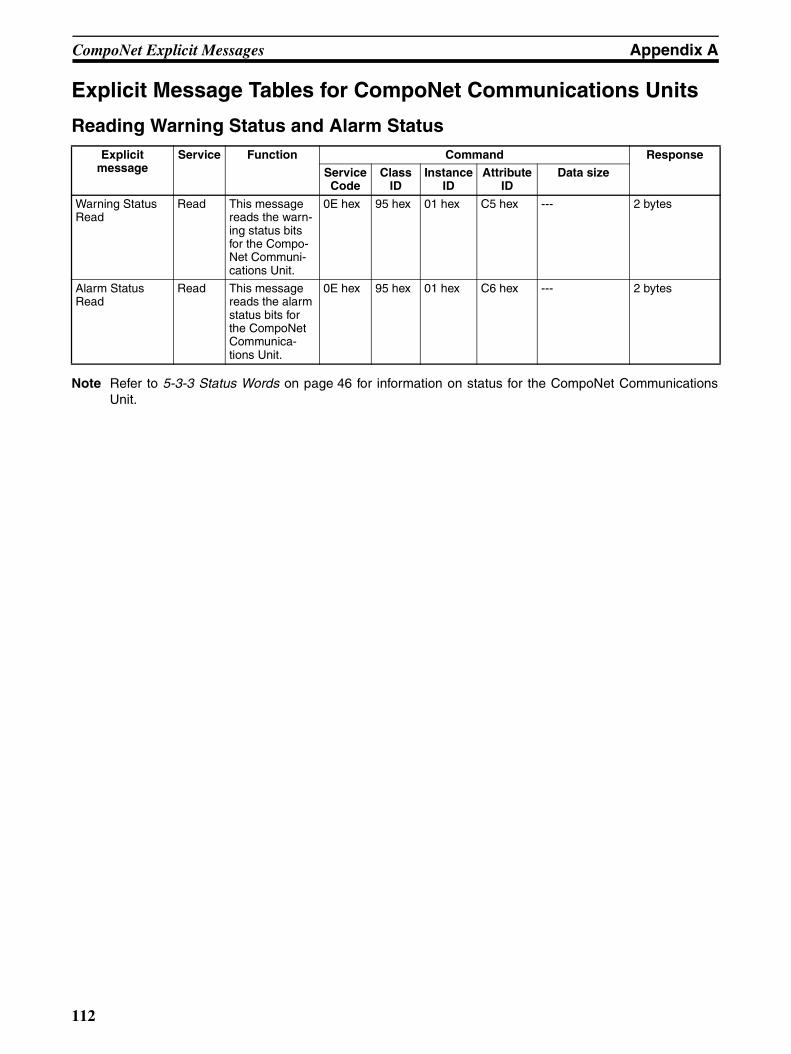
CompoNet Explicit Messages Appendix A
Explicit Message Tables for CompoNet Communications Units
Reading Warning Status and Alarm Status
Note Refer to 5-3-3 Status Words on page 46 for information on status for the CompoNet CommunicationsUnit.
Explicit message
Service Function Command Response
ServiceCode
ClassID
InstanceID
AttributeID
Data size
Warning Status Read
Read This message reads the warn-ing status bits for the Compo-Net Communi-cations Unit.
0E hex 95 hex 01 hex C5 hex --- 2 bytes
Alarm Status Read
Read This message reads the alarm status bits for the CompoNet Communica-tions Unit.
0E hex 95 hex 01 hex C6 hex --- 2 bytes
112
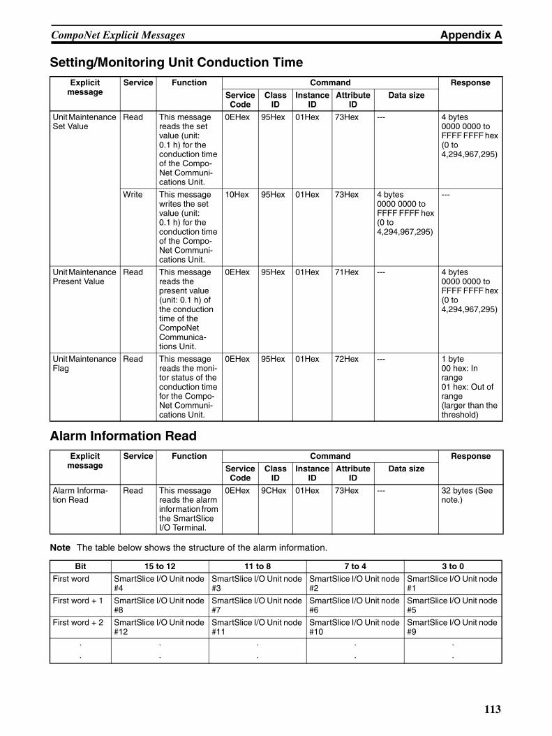
CompoNet Explicit Messages Appendix A
Setting/Monitoring Unit Conduction Time
Alarm Information Read
Note The table below shows the structure of the alarm information.
Explicit message
Service Function Command Response
ServiceCode
ClassID
InstanceID
AttributeID
Data size
Unit Maintenance Set Value
Read This message reads the set value (unit: 0.1 h) for the conduction time of the Compo-Net Communi-cations Unit.
0EHex 95Hex 01Hex 73Hex --- 4 bytes 0000 0000 to FFFF FFFF hex (0 to 4,294,967,295)
Write This message writes the set value (unit: 0.1 h) for the conduction time of the Compo-Net Communi-cations Unit.
10Hex 95Hex 01Hex 73Hex 4 bytes 0000 0000 to FFFF FFFF hex (0 to 4,294,967,295)
---
Unit Maintenance Present Value
Read This message reads the present value (unit: 0.1 h) of the conduction time of the CompoNet Communica-tions Unit.
0EHex 95Hex 01Hex 71Hex --- 4 bytes 0000 0000 to FFFF FFFF hex (0 to 4,294,967,295)
Unit Maintenance Flag
Read This message reads the moni-tor status of the conduction time for the Compo-Net Communi-cations Unit.
0EHex 95Hex 01Hex 72Hex --- 1 byte 00 hex: In range01 hex: Out of range(larger than the threshold)
Explicit message
Service Function Command Response
ServiceCode
ClassID
InstanceID
AttributeID
Data size
Alarm Informa-tion Read
Read This message reads the alarm information from the SmartSlice I/O Terminal.
0EHex 9CHex 01Hex 73Hex --- 32 bytes (See note.)
Bit 15 to 12 11 to 8 7 to 4 3 to 0
First word SmartSlice I/O Unit node #4
SmartSlice I/O Unit node #3
SmartSlice I/O Unit node #2
SmartSlice I/O Unit node #1
First word + 1 SmartSlice I/O Unit node #8
SmartSlice I/O Unit node #7
SmartSlice I/O Unit node #6
SmartSlice I/O Unit node #5
First word + 2 SmartSlice I/O Unit node #12
SmartSlice I/O Unit node #11
SmartSlice I/O Unit node #10
SmartSlice I/O Unit node #9
· · · · ·
· · · · ·
113
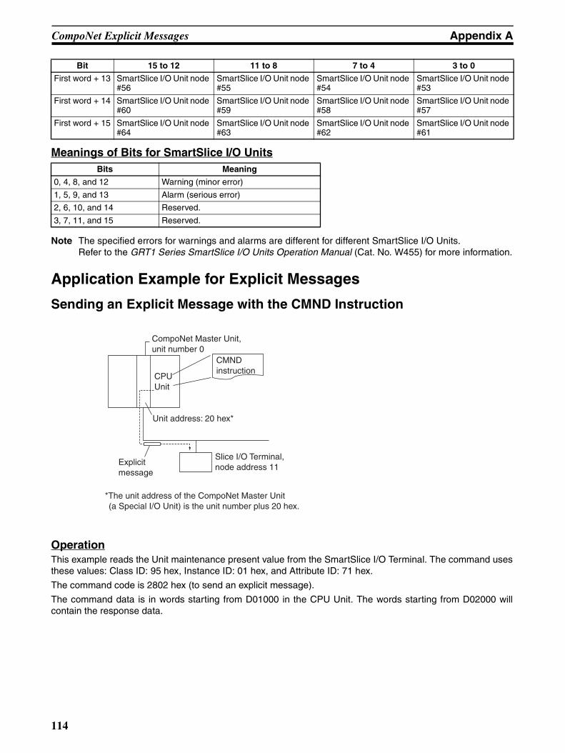
CompoNet Explicit Messages Appendix A
Meanings of Bits for SmartSlice I/O Units
Note The specified errors for warnings and alarms are different for different SmartSlice I/O Units. Refer to the GRT1 Series SmartSlice I/O Units Operation Manual (Cat. No. W455) for more information.
Application Example for Explicit Messages
Sending an Explicit Message with the CMND Instruction
OperationThis example reads the Unit maintenance present value from the SmartSlice I/O Terminal. The command usesthese values: Class ID: 95 hex, Instance ID: 01 hex, and Attribute ID: 71 hex.
The command code is 2802 hex (to send an explicit message).
The command data is in words starting from D01000 in the CPU Unit. The words starting from D02000 willcontain the response data.
First word + 13 SmartSlice I/O Unit node #56
SmartSlice I/O Unit node #55
SmartSlice I/O Unit node #54
SmartSlice I/O Unit node #53
First word + 14 SmartSlice I/O Unit node #60
SmartSlice I/O Unit node #59
SmartSlice I/O Unit node #58
SmartSlice I/O Unit node #57
First word + 15 SmartSlice I/O Unit node #64
SmartSlice I/O Unit node #63
SmartSlice I/O Unit node #62
SmartSlice I/O Unit node #61
Bits Meaning
0, 4, 8, and 12 Warning (minor error)
1, 5, 9, and 13 Alarm (serious error)
2, 6, 10, and 14 Reserved.
3, 7, 11, and 15 Reserved.
Bit 15 to 12 11 to 8 7 to 4 3 to 0
Explicitmessage
CompoNet Master Unit, unit number 0
CPUUnit
Slice I/O Terminal, node address 11
CMNDinstruction
Unit address: 20 hex*
*The unit address of the CompoNet Master Unit (a Special I/O Unit) is the unit number plus 20 hex.
114
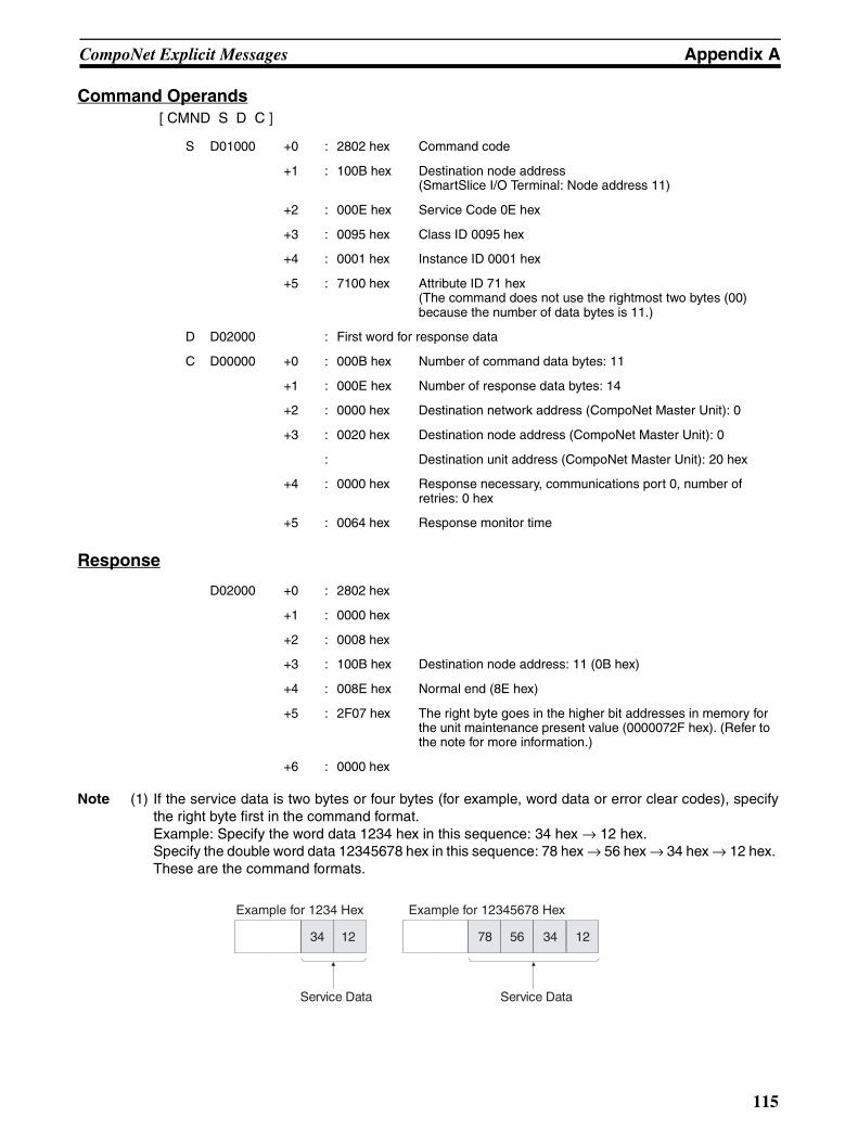
CompoNet Explicit Messages Appendix A
Command Operands[ CMND S D C ]
Response
Note (1) If the service data is two bytes or four bytes (for example, word data or error clear codes), specifythe right byte first in the command format. Example: Specify the word data 1234 hex in this sequence: 34 hex → 12 hex. Specify the double word data 12345678 hex in this sequence: 78 hex → 56 hex → 34 hex → 12 hex. These are the command formats.
S D01000 +0 : 2802 hex Command code
+1 : 100B hex Destination node address (SmartSlice I/O Terminal: Node address 11)
+2 : 000E hex Service Code 0E hex
+3 : 0095 hex Class ID 0095 hex
+4 : 0001 hex Instance ID 0001 hex
+5 : 7100 hex Attribute ID 71 hex(The command does not use the rightmost two bytes (00) because the number of data bytes is 11.)
D D02000 : First word for response data
C D00000 +0 : 000B hex Number of command data bytes: 11
+1 : 000E hex Number of response data bytes: 14
+2 : 0000 hex Destination network address (CompoNet Master Unit): 0
+3 : 0020 hex Destination node address (CompoNet Master Unit): 0
: Destination unit address (CompoNet Master Unit): 20 hex
+4 : 0000 hex Response necessary, communications port 0, number of retries: 0 hex
+5 : 0064 hex Response monitor time
D02000 +0 : 2802 hex
+1 : 0000 hex
+2 : 0008 hex
+3 : 100B hex Destination node address: 11 (0B hex)
+4 : 008E hex Normal end (8E hex)
+5 : 2F07 hex The right byte goes in the higher bit addresses in memory for the unit maintenance present value (0000072F hex). (Refer to the note for more information.)
+6 : 0000 hex
34 12
Service Data
78 56 34 12
Service Data
Example for 1234 Hex Example for 12345678 Hex
115
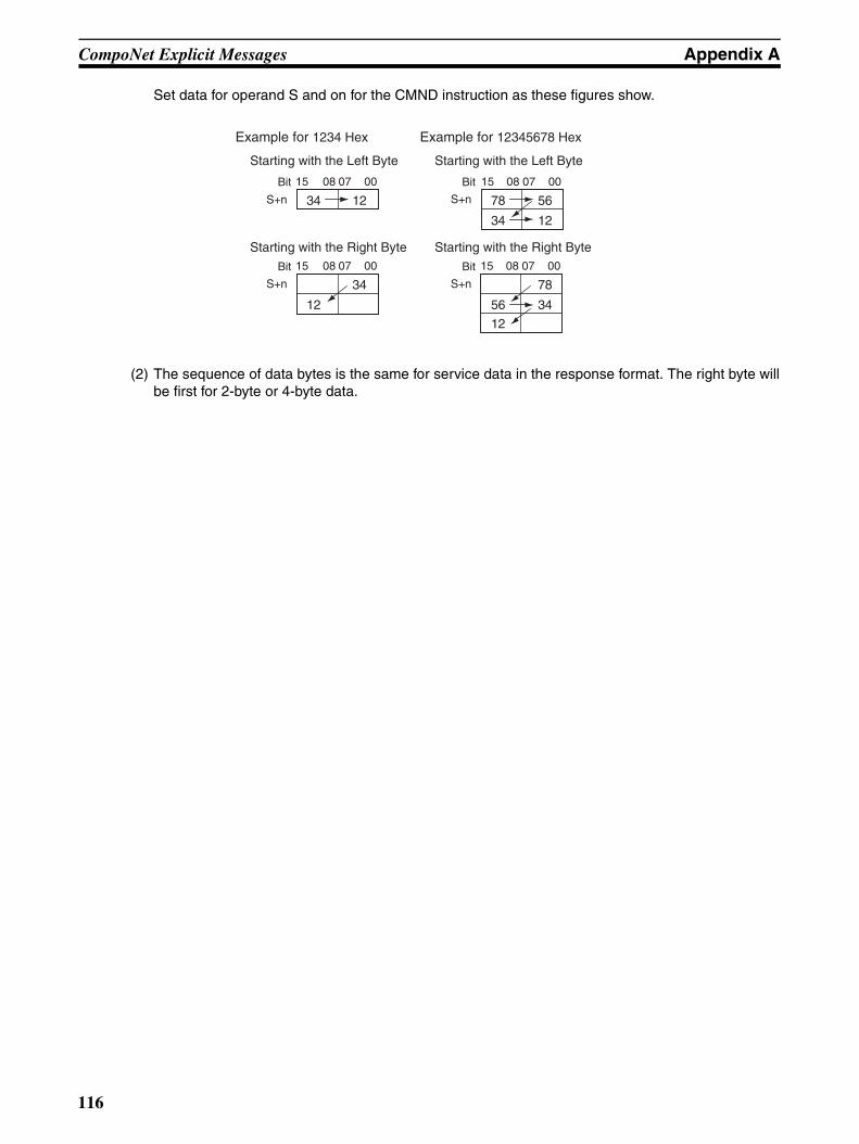
CompoNet Explicit Messages Appendix A
Set data for operand S and on for the CMND instruction as these figures show.
(2) The sequence of data bytes is the same for service data in the response format. The right byte willbe first for 2-byte or 4-byte data.
00
S+n 34 12
15 08 07
S+n
12
34
15 08 07 00
S+n
56
12
78
34
15 08 07 00
S+n 78
34
56
12
15 08 07 00Bit Bit
Bit Bit
Example for 1234 Hex
Starting with the Left Byte Starting with the Left Byte
Starting with the Right Byte Starting with the Right Byte
Example for 12345678 Hex
116
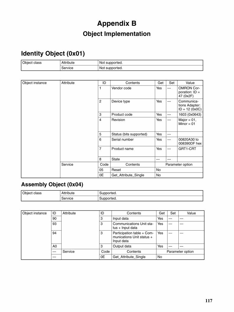
Appendix BObject Implementation
Identity Object (0x01)
Assembly Object (0x04)
Object class Attribute Not supported.
Service Not supported.
Object instance Attribute ID Contents Get Set Value
1 Vendor code Yes --- OMRON Cor-poration: ID = 47 (0x2F)
2 Device type Yes --- Communica-tions Adapter: ID = 12 (0x0C)
3 Product code Yes --- 1603 (0x0643)
4 Revision Yes --- Major = 01, Minor = 01
5 Status (bits supported) Yes ---
6 Serial number Yes --- 00820A30 to 008390DF hex
7 Product name Yes --- GRT1-CRT
8 State --- ---
Service Code Contents Parameter option
05 Reset No
0E Get_Attribute_Single No
Object class Attribute Supported.
Service Supported.
Object instance ID Attribute ID Contents Get Set Value
90 3 Input data Yes --- ---
93 3 Communications Unit sta-tus + Input data
Yes --- ---
94 3 Participation table + Com-munications Unit status + Input data
Yes --- ---
A0 3 Output data Yes --- ---
--- Service Code Contents Parameter option
--- 0E Get_Attribute_Single No
117
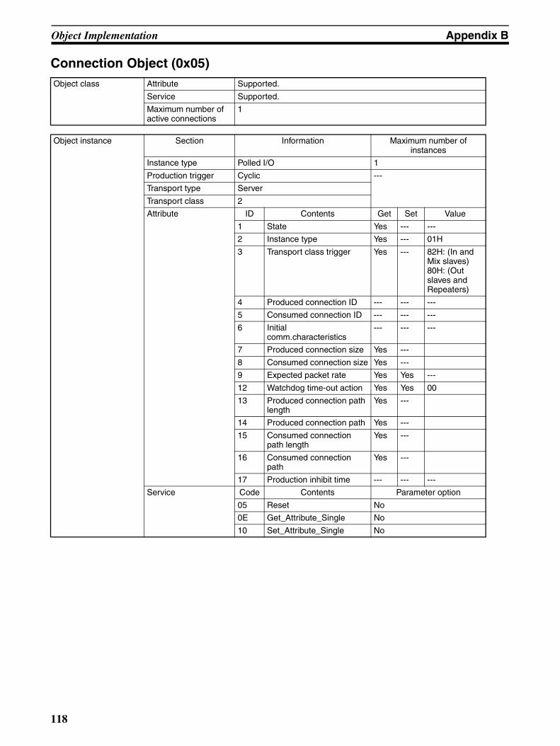
Object Implementation Appendix B
Connection Object (0x05)Object class Attribute Supported.
Service Supported.
Maximum number of active connections
1
Object instance Section Information Maximum number of instances
Instance type Polled I/O 1
Production trigger Cyclic ---
Transport type Server
Transport class 2
Attribute ID Contents Get Set Value
1 State Yes --- ---
2 Instance type Yes --- 01H
3 Transport class trigger Yes --- 82H: (In and Mix slaves)80H: (Out slaves and Repeaters)
4 Produced connection ID --- --- ---
5 Consumed connection ID --- --- ---
6 Initial comm.characteristics
--- --- ---
7 Produced connection size Yes ---
8 Consumed connection size Yes ---
9 Expected packet rate Yes Yes ---
12 Watchdog time-out action Yes Yes 00
13 Produced connection path length
Yes ---
14 Produced connection path Yes ---
15 Consumed connection path length
Yes ---
16 Consumed connection path
Yes ---
17 Production inhibit time --- --- ---
Service Code Contents Parameter option
05 Reset No
0E Get_Attribute_Single No
10 Set_Attribute_Single No
118
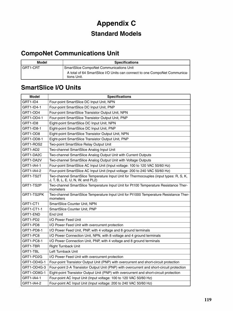
Appendix CStandard Models
CompoNet Communications Unit
SmartSlice I/O Units
Model Specifications
GRT1-CRT SmartSlice CompoNet Communications Unit A total of 64 SmartSlice I/O Units can connect to one CompoNet Communica-tions Unit.
Model Specifications
GRT1-ID4 Four-point SmartSlice DC Input Unit, NPN
GRT1-ID4-1 Four-point SmartSlice DC Input Unit, PNP
GRT1-OD4 Four-point SmartSlice Transistor Output Unit, NPN
GRT1-OD4-1 Four-point SmartSlice Transistor Output Unit, PNP
GRT1-ID8 Eight-point SmartSlice DC Input Unit, NPN
GRT1-ID8-1 Eight-point SmartSlice DC Input Unit, PNP
GRT1-OD8 Eight-point SmartSlice Transistor Output Unit, NPN
GRT1-OD8-1 Eight-point SmartSlice Transistor Output Unit, PNP
GRT1-ROS2 Two-point SmartSlice Relay Output Unit
GRT1-AD2 Two-channel SmartSlice Analog Input Unit
GRT1-DA2C Two-channel SmartSlice Analog Output Unit with Current Outputs
GRT1-DA2V Two-channel SmartSlice Analog Output Unit with Voltage Outputs
GRT1-IA4-1 Four-point SmartSlice AC Input Unit (Input voltage: 100 to 120 VAC 50/60 Hz)
GRT1-IA4-2 Four-point SmartSlice AC Input Unit (Input voltage: 200 to 240 VAC 50/60 Hz)
GRT1-TS2T Two-channel SmartSlice Temperature Input Unit for Thermocouples (input types: R, S, K, J, T, B, L, E, U, N, W, and PL2)
GRT1-TS2P Two-channel SmartSlice Temperature Input Unit for Pt100 Temperature Resistance Ther-mometers
GRT1-TS2PK Two-channel SmartSlice Temperature Input Unit for Pt1000 Temperature Resistance Ther-mometers
GRT1-CT1 SmartSlice Counter Unit, NPN
GRT1-CT1-1 SmartSlice Counter Unit, PNP
GRT1-END End Unit
GRT1-PD2 I/O Power Feed Unit
GRT1-PD8 I/O Power Feed Unit with overcurrent protection
GRT1-PD8-1 I/O Power Feed Unit, PNP, with 4 voltage and 8 ground terminals
GRT1-PC8 I/O Power Connection Unit, NPN, with 8 voltage and 4 ground terminals
GRT1-PC8-1 I/O Power Connection Unit, PNP, with 4 voltage and 8 ground terminals
GRT1-TBR Right Turnback Unit
GRT1-TBL Left Turnback Unit
GRT1-PD2G I/O Power Feed Unit with overcurrent protection
GRT1-OD4G-1 Four-point Transistor Output Unit (PNP) with overcurrent and short-circuit protection
GRT1-OD4G-3 Four-point 2-A Transistor Output Unit (PNP) with overcurrent and short-circuit protection
GRT1-OD8G-1 Eight-point Transistor Output Unit (PNP) with overcurrent and short-circuit protection
GRT1-IA4-1 Four-point AC Input Unit (Input voltage: 100 to 120 VAC 50/60 Hz)
GRT1-IA4-2 Four-point AC Input Unit (Input voltage: 200 to 240 VAC 50/60 Hz)
119
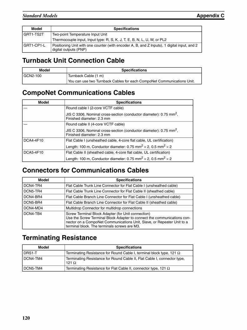
Standard Models Appendix C
Turnback Unit Connection Cable
CompoNet Communications Cables
Connectors for Communications Cables
Terminating Resistance
GRT1-TS2T Two-point Temperature Input UnitThermocouple input, Input type: R, S, K, J, T, E, B, N, L, U, W, or PL2
GRT1-CP1-L Positioning Unit with one counter (with encoder A, B, and Z Inputs), 1 digital input, and 2 digital outputs (PNP)
Model Specifications
GCN2-100 Turnback Cable (1 m)
You can use two Turnback Cables for each CompoNet Communications Unit.
Model Specifications
--- Round cable I (2-core VCTF cable)
JIS C 3306, Nominal cross-section (conductor diameter): 0.75 mm2, Finished diameter: 2.3 mm
--- Round cable II (4-core VCTF cable)
JIS C 3306, Nominal cross-section (conductor diameter): 0.75 mm2, Finished diameter: 2.3 mm
DCA4-4F10 Flat Cable I (unsheathed cable, 4-core flat cable, UL certification)
Length: 100 m, Conductor diameter: 0.75 mm2 × 2, 0.5 mm2 × 2
DCA5-4F10 Flat Cable II (sheathed cable, 4-core flat cable, UL certification)
Length: 100 m, Conductor diameter: 0.75 mm2 × 2, 0.5 mm2 × 2
Model Specifications
DCN4-TR4 Flat Cable Trunk Line Connector for Flat Cable I (unsheathed cable)
DCN5-TR4 Flat Cable Trunk Line Connector for Flat Cable II (sheathed cable)
DCN4-BR4 Flat Cable Branch Line Connector for Flat Cable I (unsheathed cable)
DCN5-BR4 Flat Cable Branch Line Connector for Flat Cable II (sheathed cable)
DCN4-MD4 Multidrop Connector for multidrop connections
DCN4-TB4 Screw Terminal Block Adapter (for Unit connection)Use the Screw Terminal Block Adapter to connect the communications con-nector on a CompoNet Communications Unit, Slave, or Repeater Unit to a terminal block. The terminals screws are M3.
Model Specifications
DRS1-T Terminating Resistance for Round Cable I, terminal block type, 121 ΩDCN4-TM4 Terminating Resistance for Round Cable II, Flat Cable I, connector type,
121 ΩDCN5-TM4 Terminating Resistance for Flat Cable II, connector type, 121 Ω
Model Specifications
120
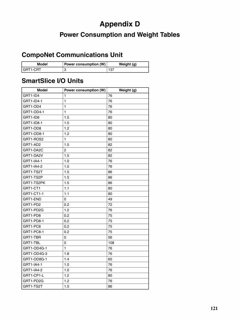
Appendix DPower Consumption and Weight Tables
CompoNet Communications Unit
SmartSlice I/O Units
Model Power consumption (W) Weight (g)
GRT1-CRT 3 137
Model Power consumption (W) Weight (g)
GRT1-ID4 1 76
GRT1-ID4-1 1 76
GRT1-OD4 1 76
GRT1-OD4-1 1 76
GRT1-ID8 1.5 80
GRT1-ID8-1 1.5 80
GRT1-OD8 1.2 80
GRT1-OD8-1 1.2 80
GRT1-ROS2 1 80
GRT1-AD2 1.5 82
GRT1-DA2C 2 82
GRT1-DA2V 1.5 82
GRT1-IA4-1 1.0 76
GRT1-IA4-2 1.0 76
GRT1-TS2T 1.5 86
GRT1-TS2P 1.5 86
GRT1-TS2PK 1.5 86
GRT1-CT1 1.1 80
GRT1-CT1-1 1.1 80
GRT1-END 0 49
GRT1-PD2 0.2 72
GRT1-PD2G 1.2 76
GRT1-PD8 0.2 75
GRT1-PD8-1 0.2 75
GRT1-PC8 0.2 75
GRT1-PC8-1 0.2 75
GRT1-TBR 0 56
GRT1-TBL 0 108
GRT1-OD4G-1 1 76
GRT1-OD4G-3 1.8 76
GRT1-OD8G-1 1.4 60
GRT1-IA4-1 1.0 76
GRT1-IA4-2 1.0 76
GRT1-CP1-L 1.2 80
GRT1-PD2G 1.2 76
GRT1-TS2T 1.5 86
121

Power Consumption and Weight Tables Appendix D
122

Appendix ETotal I/O Current Consumption Table
Model Total I/O current consumption (mA)
GRT1-ID4 33
GRT1-ID4-1 33
GRT1-OD4 12
GRT1-OD4-1 12
GRT1-ID8 38
GRT1-ID8-1 38
GRT1-OD8 8
GRT1-OD8-1 8
GRT1-ROS2 30
GRT1-AD2 0
GRT1-DA2C 0
GRT1-DA2V 0
GRT1-IA4-1 0
GRT1-IA4-2 0
GRT1-TS2T 0
GRT1-TS2P 0
GRT1-TS2PK 0
GRT1-CT1 21
GRT1-CT1-1 21
GRT1-END 0
GRT1-PD2 4
GRT1-PD2G 19
GRT1-PD8 4
GRT1-PD8-1 4
GRT1-PC8 4
GRT1-PC8-1 4
GRT1-TBR 0
GRT1-TBL 4
GRT1-OD4G-1 12
GRT1-OD4G-3 10
GRT1-OD8G-1 17
GRT1-IA4-1 0
GRT1-IA4-2 0
GRT1-TS2T 0
GRT1-CP1-L 28
GRT1-PD2G 19
123

Total I/O Current Consumption Table Appendix E
124
Index
Aalarm status
CompoNet Communications Unit, 49
allocation
starting point, 41
Automatic Restore Monitor Flag, 48, 59
Bbackup, 19
checking results, 57
function, 57
procedure, 57
Base Block, 13
baud rate
automatic recognition, 59
Bit Units, 43
Ccalendar, 79
communications cable, 30
communications connector, 12, 30
CompoNet Communications Unit Error Flag, 48
CompoNet Master Unit, 6connection timeout, 101
connector
CompoNet communications, 12
current consumption
total I/O current consumption, 36
CX-Integrator, 6
Ddimensions, 9DIN Tracks, 22
DIP switch, 12, 18
pin 1 (REGS), 18
pin 2 (I/O), 19
pin 3 (ADR), 19
pin 4 (BACK), 19
Dummy Units, 60, 70
EEnd Plate, 22
installing, 26
End Unit, 6installing, 25
error flags, 47
error history
I/O communications, 76
network communications, 75
Fferrules, 32
connecting, 32
disconnecting, 33
flags, 46
Flat Cable, 30
Flat Cable Branch Line Connector, 30
Flat Connector Plug, 30
II/O allocation, 42
CX-Integrator, 51
software setting, 60
I/O configuration
information, 54
I/O memory, 42
allocated data, 42
I/O Power Feed Units, 37
I/O power supply, 31, 36, 37
connecting, 34
terminals, 34
I/O PWR indicator, 17
I/O Refreshing Flag, 48
I/O response time, 90
maximum value, 90
minimum value, 90
I/O signal lines, 38
I/O size error, 104
indicators, 12
Input Area, 43
installation, 21
LLast Maintenance Date, 77
logic error
table settings, 103
125

Index
MMain Block, 13
memory access error, 103
message communications
number of bytes, 93
time required, 93
mounting tracks, 22
MS indicator, 14
Nnode address, 18, 40
duplicated, 101
NS indicator, 15
OOutput Area, 43
Pparameters
editing, 70
power consumption
total Unit power consumption, 36
power supplies
recommended, 31
types, 31
power supply terminals, 31
Rreception error
backup data, 104
Registration Table, 18, 54
clearing, 56
making, 54
Verification Error, 56
verifying, 55
release button, 33
remote I/O communications, 90
replacing
online, 59
restore, 19
automatic, 58
procedure, 58
restrictions
installation, 44
rotary switches, 12, 18, 40
round cable, 30
SScrew Terminal Block Adapter, 30
screwdriver, 33
screwless clamp terminals, 31, 38
applicable wires, 32
settings
showing, 67
slave duplication error, 104
slice bus, 31
SmartSlice Bus Communications Error Flag, 47
SmartSlice configuration error, 104
SmartSlice I/O Terminals, 2installation, 22
SmartSlice I/O Unit Alarm Flag, 47
SmartSlice I/O Unit Warning Flag, 47
SmartSlice I/O Units, 6connecting, 24
editing parameters, 70
Software I/O Allocation Mode, 19, 62
starting in, 62
Software Setting Table, 60
clearing, 66
downloading, 64
making, 63
specifications
communications, 7CompoNet Communications Unit, 7SmartSlice, 7
status, 43
CompoNet Communications Unit, 46
status area, 47
TTerminal Block, 13
terminals
I/O power supply, 12
Unit power supply, 12
total power ON time, 71
transmission error, 104
troubleshooting, 95
TS indicator, 16
126
Index
Turnback Cable, 6, 36
connecting, 35
Turnback Units, 6, 36, 37
installing, 27
Uunit comments, 73
reading, 74
writing, 74
Unit Conduction Time
monitoring, 72
setting the threshold, 72
Unit Conduction Time Monitor, 71
threshold, 71
Unit Maintenance Flag, 48, 71
unit numbers, 41, 42
Unit power supply, 31, 36, 37
connecting, 33
terminals, 33
UNIT PWR indicator, 17
unused bits, 44
Vverification errors, 102
Wwarning status
CompoNet Communications Unit, 49
WDT error, 102
wires
connecting, 32, 33
disconnecting, 33
Word Units, 43
127

Index
128
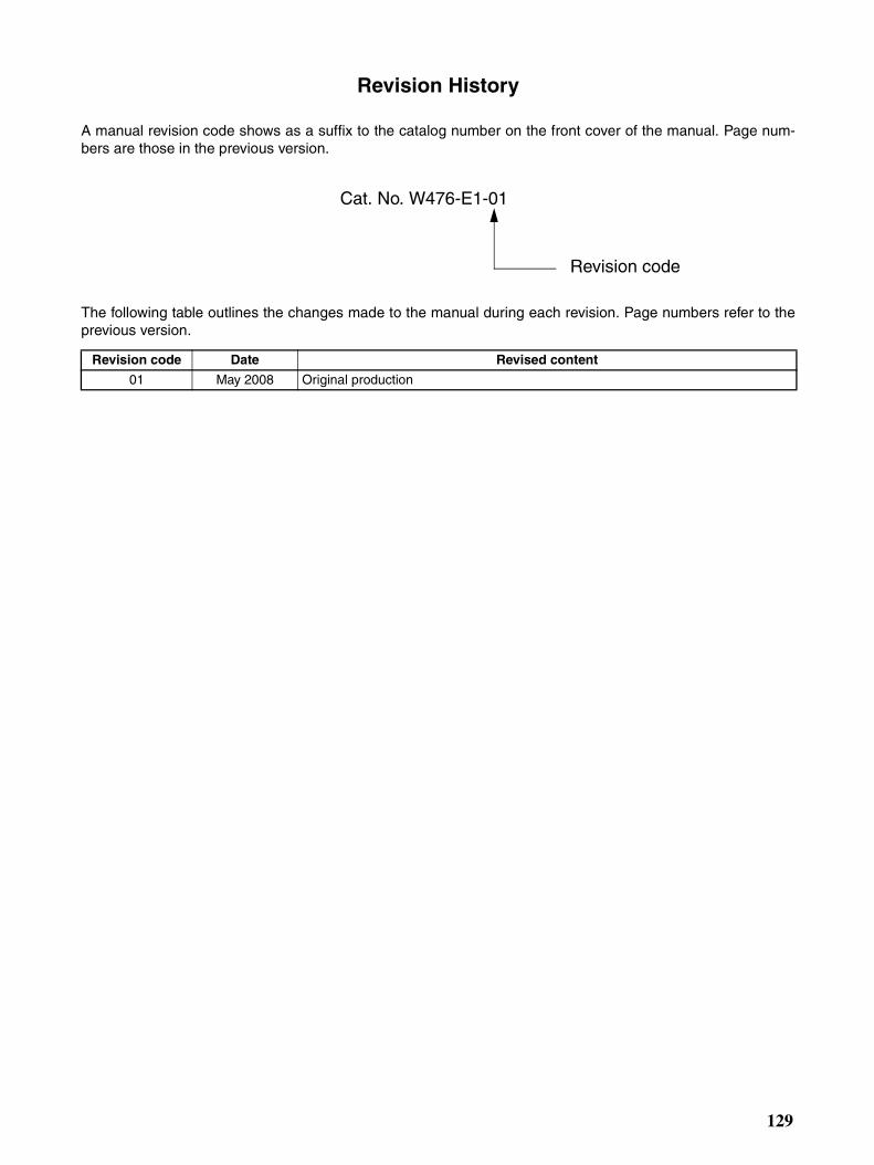
Revision History
A manual revision code shows as a suffix to the catalog number on the front cover of the manual. Page num-bers are those in the previous version.
The following table outlines the changes made to the manual during each revision. Page numbers refer to theprevious version.
Revision code Date Revised content
01 May 2008 Original production
Cat. No. W476-E1-01
Revision code
129

Revision History
130