Embed Size (px)
Citation preview

1
Grundfos MP1 Manual
www.envieq.com
2
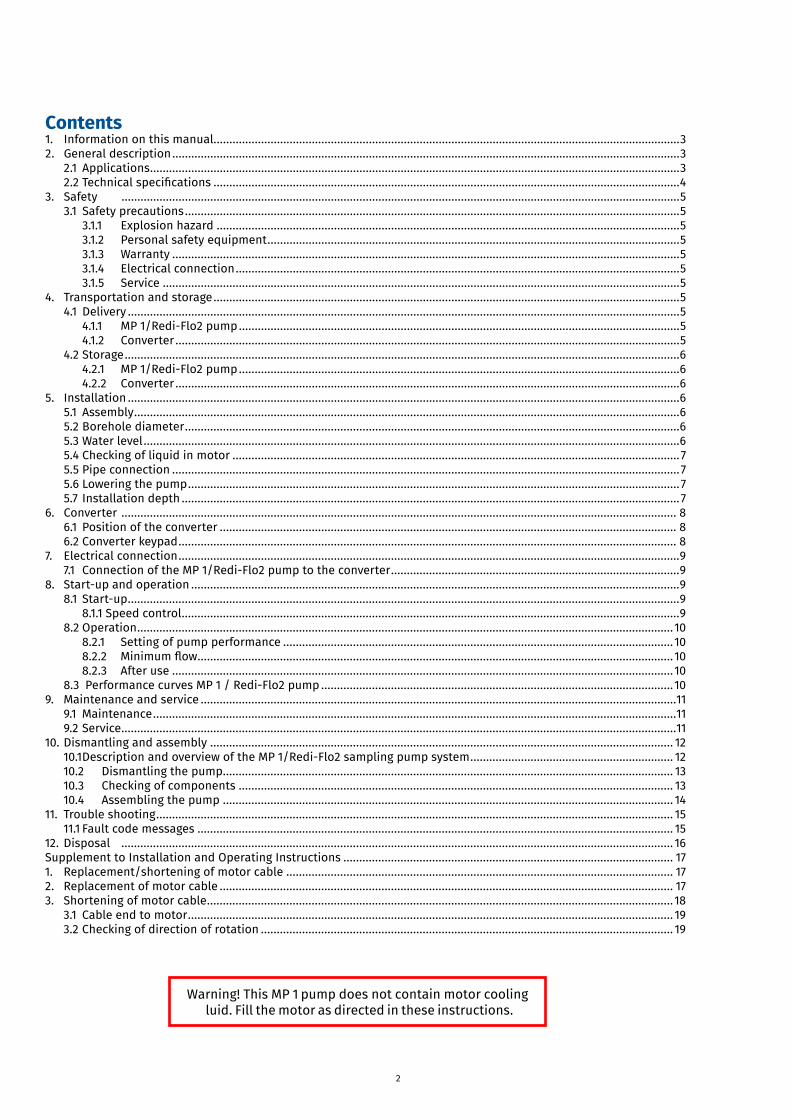
Contents1. Information on this manual...................................................................................................................................................32. General description ................................................................................................................................................................3
2.1 Applications .......................................................................................................................................................................32.2Technicalspecifications ...................................................................................................................................................4
3. Safety ................................................................................................................................................................................53.1 Safety precautions ............................................................................................................................................................5
3.1.1 Explosion hazard ..................................................................................................................................................53.1.2 Personal safety equipment ..................................................................................................................................5
3.1.3 Warranty ................................................................................................................................................................5 3.1.4 Electrical connection ............................................................................................................................................5 3.1.5 Service ...................................................................................................................................................................54. Transportation and storage ...................................................................................................................................................5
4.1 Delivery ..............................................................................................................................................................................54.1.1 MP 1/Redi-Flo2 pump ...........................................................................................................................................5
4.1.2 Converter ...............................................................................................................................................................54.2 Storage ...............................................................................................................................................................................6
4.2.1 MP 1/Redi-Flo2 pump ...........................................................................................................................................6 4.2.2 Converter ...............................................................................................................................................................65. Installation ..............................................................................................................................................................................6
5.1 Assembly ............................................................................................................................................................................65.2 Borehole diameter ............................................................................................................................................................65.3 Water level .........................................................................................................................................................................65.4 Checking of liquid in motor .............................................................................................................................................75.5 Pipe connection ................................................................................................................................................................75.6 Lowering the pump ...........................................................................................................................................................75.7 Installation depth .............................................................................................................................................................7
6. Converter ............................................................................................................................................................................... 86.1 Position of the converter ................................................................................................................................................ 86.2 Converter keypad ............................................................................................................................................................. 8
7. Electrical connection ..............................................................................................................................................................97.1 Connection of the MP 1/Redi-Flo2 pump to the converter ...........................................................................................9
8. Start-up and operation ..........................................................................................................................................................98.1 Start-up ..............................................................................................................................................................................9
8.1.1 Speed control .............................................................................................................................................................98.2 Operation ......................................................................................................................................................................... 10
8.2.1 Setting of pump performance ........................................................................................................................... 108.2.2 Minimumflow ...................................................................................................................................................... 10
8.2.3 After use .............................................................................................................................................................. 108.3 Performance curves MP 1 / Redi-Flo2 pump ............................................................................................................... 10
9. Maintenance and service ......................................................................................................................................................119.1 Maintenance .....................................................................................................................................................................119.2 Service ...............................................................................................................................................................................11
10. Dismantling and assembly .................................................................................................................................................. 1210.1 Description and overview of the MP 1/Redi-Flo2 sampling pump system ................................................................ 1210.2 Dismantling the pump.............................................................................................................................................. 1310.3 Checking of components ......................................................................................................................................... 1310.4 Assembling the pump .............................................................................................................................................. 14
11. Trouble shooting ................................................................................................................................................................... 1511.1 Fault code messages ...................................................................................................................................................... 15
12. Disposal .............................................................................................................................................................................. 16Supplement to Installation and Operating Instructions ........................................................................................................ 171. Replacement/shortening of motor cable .......................................................................................................................... 172. Replacement of motor cable ............................................................................................................................................... 173. Shortening of motor cable ................................................................................................................................................... 18
3.1 Cable end to motor ......................................................................................................................................................... 193.2 Checking of direction of rotation .................................................................................................................................. 19
Warning! This MP 1 pump does not contain motor coolingluid.Fillthemotorasdirectedintheseinstructions.
3
1. Information on this manualIf the text follows a mark (as shown on the left), this means that an important instruction follows.
If the text follows a mark (as shown on the left), this means that an important warning followsrelating to danger to the user or damage to the apparatus. The user is always responsible for itsown personal protection.
Italic indicated text indicates that the text concerned appears in writing on the display or theapparatus (or must be typed).
2. General descriptionPrior to installation, read these installation and operating instructions (also read the separatemanual on the frequency converter). Installation and operation must comply with local regulationsand accepted codes of good practice.
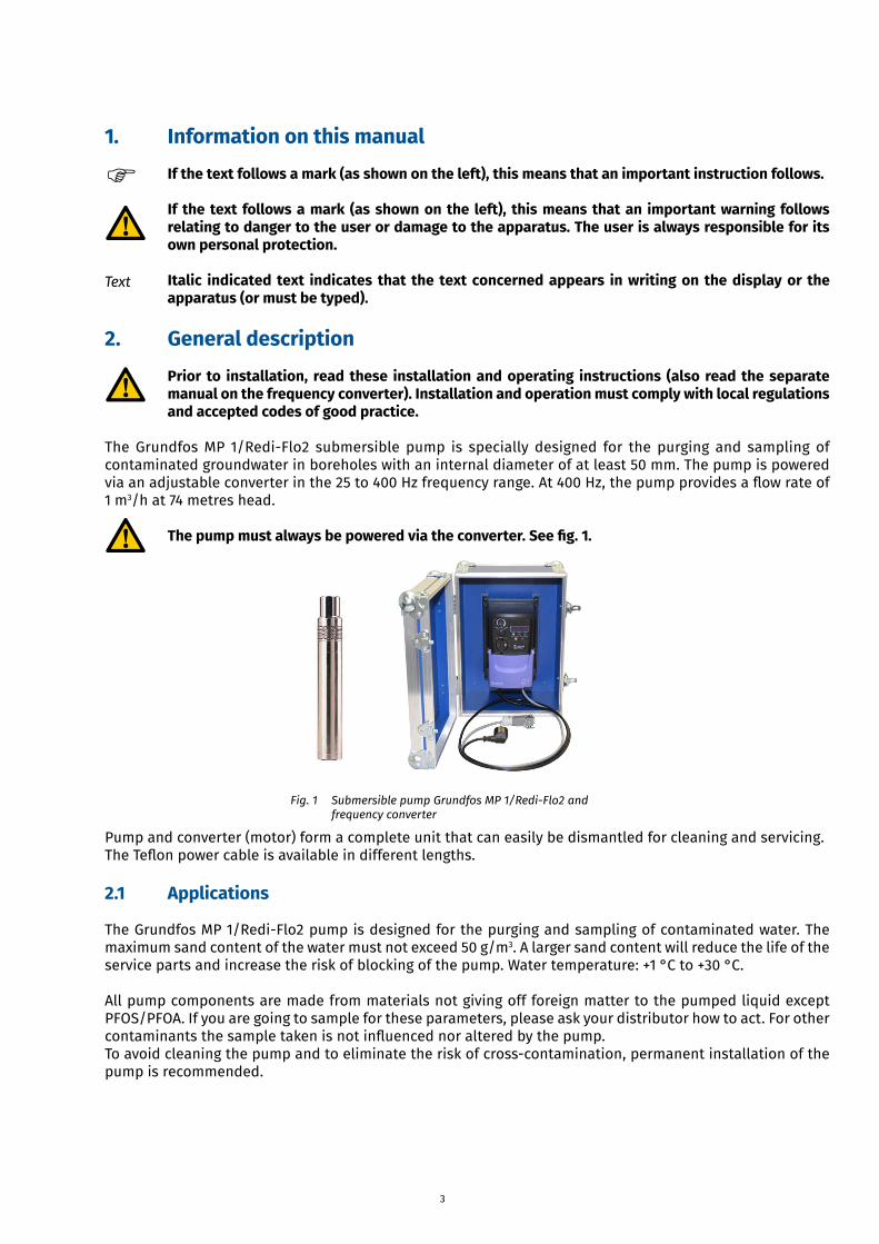
The Grundfos MP 1/Redi-Flo2 submersible pump is specially designed for the purging and sampling of contaminated groundwater in boreholes with an internal diameter of at least 50 mm. The pump is powered viaanadjustableconverterinthe25to400Hzfrequencyrange.At400Hz,thepumpprovidesaflowrateof1 m3/h at 74 metres head.
The pump must always be powered via the converter. See fig. 1.
Pump and converter (motor) form a complete unit that can easily be dismantled for cleaning and servicing.TheTeflonpowercableisavailableindifferentlengths.
2.1 Applications
The Grundfos MP 1/Redi-Flo2 pump is designed for the purging and sampling of contaminated water. The maximum sand content of the water must not exceed 50 g/m3. A larger sand content will reduce the life of the service parts and increase the risk of blocking of the pump. Water temperature: +1 °C to +30 °C.
All pump components are made from materials not giving off foreign matter to the pumped liquid except PFOS/PFOA. If you are going to sample for these parameters, please ask your distributor how to act. For other contaminantsthesampletakenisnotinfluencednoralteredbythepump.To avoid cleaning the pump and to eliminate the risk of cross-contamination, permanent installation of the pump is recommended.
Text
Fig. 1 Submersible pump Grundfos MP 1/Redi-Flo2 and frequency converter
4
It is possible to use the same pump for sampling in several boreholes if the risk of cross-contamination can be eliminated.
The MP 1/Redi-Flo2 pump is not designed for the pumping of concentrated oils, chemicals or explosive liquids.
When pumping liquids with a density or kinematic viscosity higher than that of water, a motor input power higher than the rated power is required. The maximum performance must therefore be reduced by changing the frequency.
When the MP 1/Redi-Flo2 pump is used, the regulations covering the handling of hazardous material and possible local regulations must be observed.
The MP 1/Redi-Flo2 pump is not designed for continuous operation like for instance remedial pumping. Continuous operation may reduce the life of the pump.
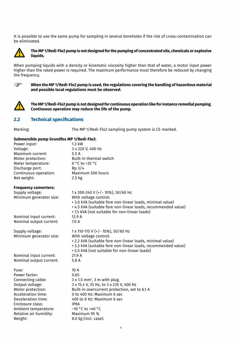
2.2 Technical specifications
Marking: The MP 1/Redi-Flo2 sampling pump system is CE-marked.
Submersible pump Grundfos MP 1/Redi-Flo2:Power input: 1.3 kWVoltage: 3 x 220 V, 400 HzMaximum current: 5.5 AMotor protection: Built-in thermal switchWater temperature: 0 °C to +35 °CDischarge port: Rp 3/4Continuous operation: Maximum 500 hoursNet weight: 2.5 kg
Frequency converters:Supply voltage: 1 x 200-240 V (+/- 10%), 50/60 HzMinimum generator size: With voltage control:
• 3.0 kVA (suitable fore non-linear loads, minimal value)• 4.5 kVA (suitable fore non-linear loads, recommended value)• 7.5 kVA (not suitable for non-linear loads)
Nominal input current: 12.9 ANominal output current: 7.0 A
Supply voltage: 1 x 110-115 V (+/- 10%), 50/60 HzMinimum generator size: With voltage control:
• 2.2 kVA (suitable fore non-linear loads, minimal value)• 3.3 kVA (suitable fore non-linear loads, recommended value)• 5.5 kVA (not suitable for non-linear loads)
Nominal input current: 21.9 ANominal output current: 5.8 A
Fuse: 10 APower factor: 0.65Connecting cable: 3 x 1.5 mm2, 3 m with plug.Output voltage: 3 x 15.4 V, 25 Hz, to 3 x 235 V, 400 HzMotor protection: Built-in overcurrent protection, set to 6.1 AAcceleration time: 0 to 400 Hz: Maximum 6 secDeceleration time: 400 to 0 Hz: Maximum 6 secEnclosure class: IP66Ambient temperature: –10 °C to +40 °CRelative air humidity: Maximum 95 %Weight: 8.0 kg (incl. case).
5
3. Safety
3.1 Safety precautions
During handling, operation, storage and transportation, the environmental regulations covering the handling of hazardous material must be observed.When the pump is taken out of operation, care must be taken to ensure that the pump contains nohazardous material that might be injurious to human health or to the environment.The motor is factory-filled with liquid (approx. 25 ml demineralised water). During operation, thisliquid is wholly or partly replaced by the contaminated water. Therefore, there is a potential risk ofcontamination and poisoning.The water delivered by the pump may be contaminated and/or toxic. The regulations covering thehandling of hazardous material must therefore be observed.
3.1.1 Explosion hazardThe pumping system is not approved as explosion-proof. Local authorities and regulations should be consulted if there is any doubt about its suitability for a certain application.
3.1.2 Personal safety equipmentWhen pumping water containing hazardous material, personal safety equipment must be used.
3.1.3 WarrantyPumps installed in accordance with these instructions and accepted codes of good practice are covered by the warranty.Any constructional change of the pumping system will invalidate the warranty. Eijkelkamp Soil & Water cannot be held responsible for possible consequential damage.
3.1.4 Electrical connectionWhen lowering/pulling out the pump, take care not to damage the motor (power) cable. The electrical connections should be carried out in accordance with local regulations.
Never fit or remove the motor cable plug from the converter unless the electricity supply to the converter has been switched off.
3.1.5 Service
Only pumps that can be certified as uncontaminated, i.e. pumps containing no hazardous and/or toxic material, may be returned to Eijkelkamp Soil & Water for servicing.
See section 9.2 Service.
4. Transportation and storage
4.1 Delivery
4.1.1 MP 1/Redi-Flo2 pumpAfter production, the pump has been ultrasonically cleaned and packed into a polyethylene bag. This means that the pump has not been in contact with dirt or detergents after cleaning and it is untouched by persons.
4.1.2 Converter
The converter should not be exposed to unnecessary shocks and should be handled like sensitive electronic equipment.
6
4.2 Storage
The pumping system should be stored in a clean and dry area.
4.2.1 MP 1/Redi-Flo2 pumpStorage temperature: –20 °C to +50 °C.If the pump has to be stored after use, it must be cleaned thoroughly before storing. See section 9. Maintenance and service.
4.2.2 ConverterThe converter should be stored in a clean and dry area. Storage temperature: –10 °C to 45 °C.
5. Installation
5.1 Assembly
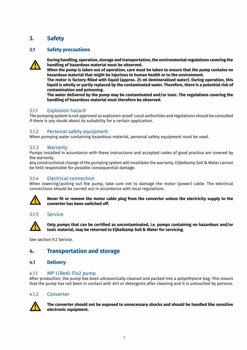
The pump can be installed either horizontally or vertically. The pump dischargeportshouldneverfallbelowthehorizontalplane.Seefig.2.
During operation, the pump must always be completely submerged in the liquid.The pump performance is controlled by changing the frequency. The installation of a valve in the discharge pipe is unnecessary and with regard to the water sample directly inappropriate.If a valve has been installed anyway, make sure that the pump is only operated against a closed valve for a very short period.Otherwise the heat generated will cause the pump to stop.If a non-return valve is installed in the discharge pipe, it must be installed at least 0.5 metres above the pump. This is necessary to ensure that the air in the pump is compressed so much that the pump contains water when it is being submerged.
5.2 Borehole diameter
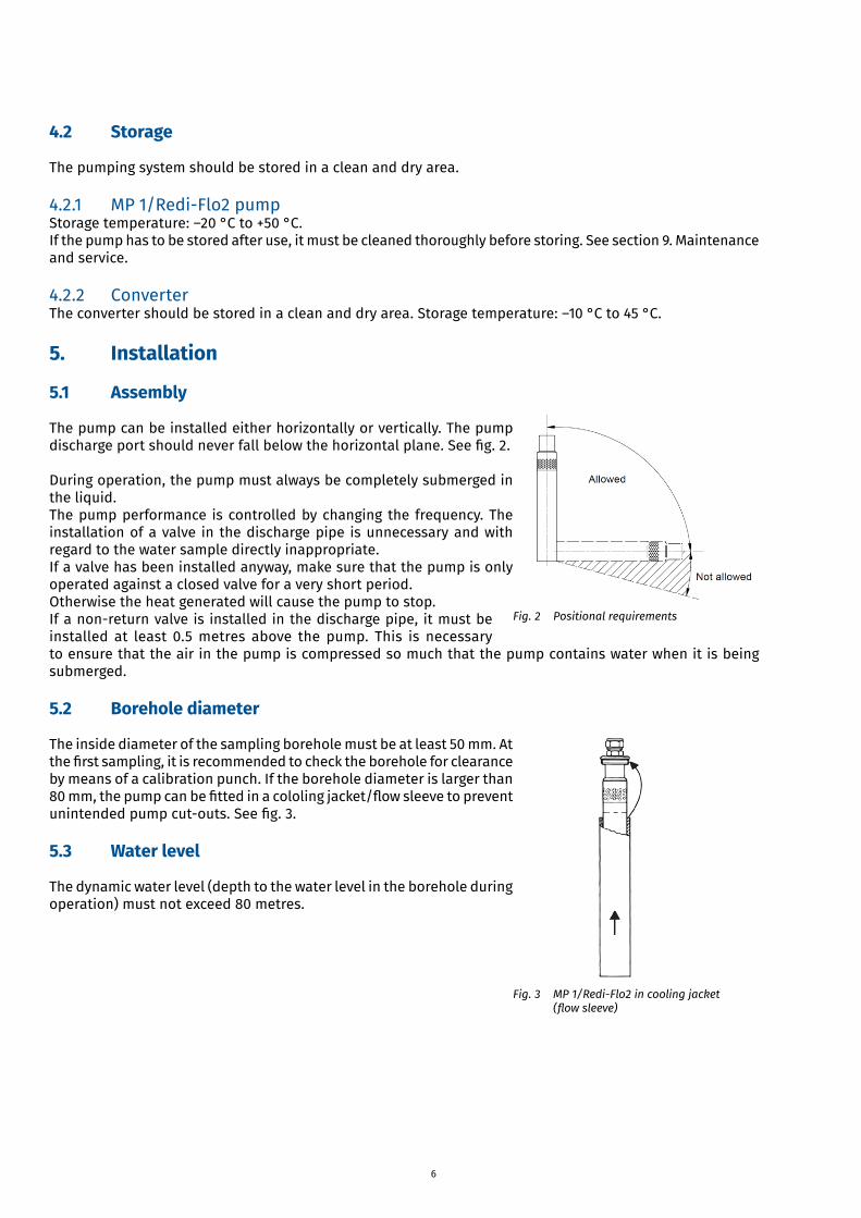
The inside diameter of the sampling borehole must be at least 50 mm. At thefirstsampling,itisrecommendedtochecktheboreholeforclearanceby means of a calibration punch. If the borehole diameter is larger than 80mm,thepumpcanbefittedinacololingjacket/flowsleevetopreventunintendedpumpcut-outs.Seefig.3.
5.3 Water level
The dynamic water level (depth to the water level in the borehole during operation) must not exceed 80 metres.
Fig. 2 Positional requirements
Fig. 3 MP 1/Redi-Flo2 in cooling jacket (flowsleeve)
7
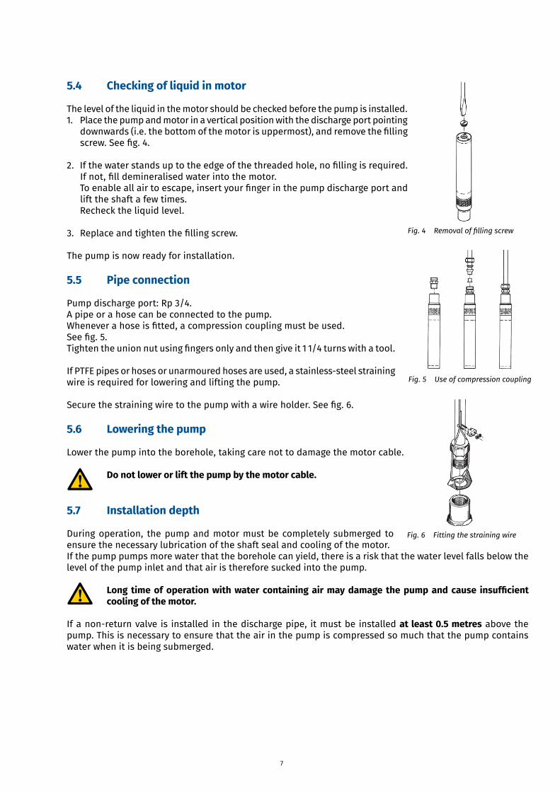
5.4 Checking of liquid in motor
The level of the liquid in the motor should be checked before the pump is installed.1. Place the pump and motor in a vertical position with the discharge port pointing
downwards(i.e.thebottomofthemotorisuppermost),andremovethefillingscrew.Seefig.4.
2. Ifthewaterstandsuptotheedgeofthethreadedhole,nofillingisrequired.Ifnot,filldemineralisedwaterintothemotor.Toenableallairtoescape,insertyourfingerinthepumpdischargeportandlift the shaft a few times.Recheck the liquid level.
3. Replaceandtightenthefillingscrew.
The pump is now ready for installation.
5.5 Pipe connection
Pump discharge port: Rp 3/4.A pipe or a hose can be connected to the pump.Wheneverahoseisfitted,acompressioncouplingmustbeused.Seefig.5.Tightentheunionnutusingfingersonlyandthengiveit11/4turnswithatool.
If PTFE pipes or hoses or unarmoured hoses are used, a stainless-steel straining wire is required for lowering and lifting the pump.
Securethestrainingwiretothepumpwithawireholder.Seefig.6.
5.6 Lowering the pump
Lower the pump into the borehole, taking care not to damage the motor cable.
Do not lower or lift the pump by the motor cable.
5.7 Installation depth
During operation, the pump and motor must be completely submerged to ensure the necessary lubrication of the shaft seal and cooling of the motor.If the pump pumps more water that the borehole can yield, there is a risk that the water level falls below the level of the pump inlet and that air is therefore sucked into the pump.
Long time of operation with water containing air may damage the pump and cause insufficient cooling of the motor.
If a non-return valve is installed in the discharge pipe, it must be installed at least 0.5 metres above the pump. This is necessary to ensure that the air in the pump is compressed so much that the pump contains water when it is being submerged.
Fig.4 Removaloffillingscrew
Fig. 5 Use of compression coupling
Fig.6 Fittingthestrainingwire
8
6. Converter
6.1 Position of the converter
Place the converter with cabinet (case) in such a way thatwater cannot enter into the cabinet.Do not close the cabinet during operation.
The converter must be installed vertically to ensure free air circulation aroundtheunit.Seefig.7.Make sure that the cabinet/converter cannot tip during operation.
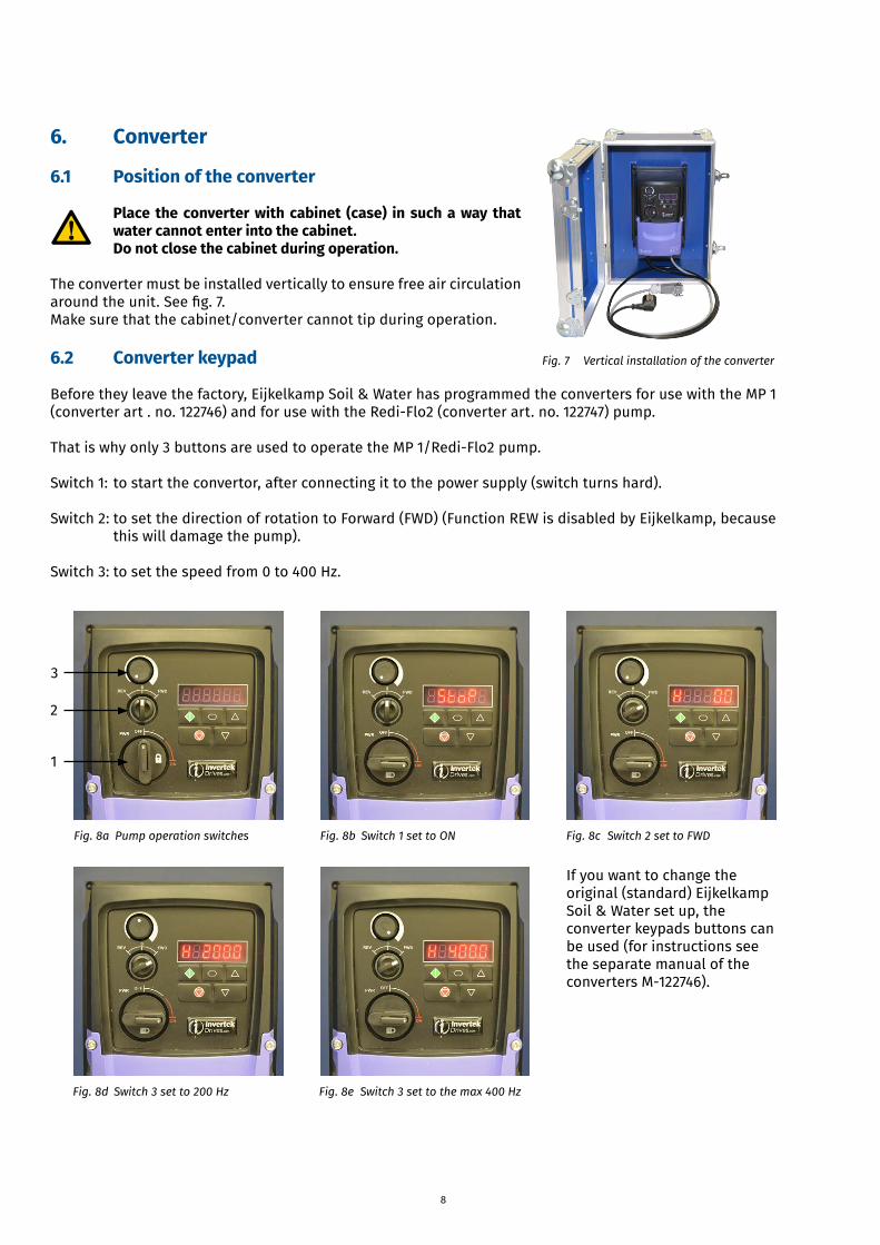
6.2 Converter keypad
Before they leave the factory, Eijkelkamp Soil & Water has programmed the converters for use with the MP 1 (converter art . no. 122746) and for use with the Redi-Flo2 (converter art. no. 122747) pump.
That is why only 3 buttons are used to operate the MP 1/Redi-Flo2 pump.
Switch 1: to start the convertor, after connecting it to the power supply (switch turns hard).
Switch 2: to set the direction of rotation to Forward (FWD) (Function REW is disabled by Eijkelkamp, because this will damage the pump).
Switch 3: to set the speed from 0 to 400 Hz.
Fig. 7 Vertical installation of the converter
Fig.8a Pumpoperationswitches
1
2
3
Fig.8b Switch1settoON Fig.8c Switch2settoFWD
Fig.8d Switch3setto200Hz Fig.8e Switch3settothemax400Hz
If you want to change the original (standard) Eijkelkamp Soil & Water set up, the converter keypads buttons can be used (for instructions see the separate manual of the converters M-122746).
9
7. Electrical connectionBefore starting work on the pump, make sure that the electricity supply has been switched off andthat it cannot be accidentally switched on.
Use the separate manual (M122746) on both converters for instructions on connecting the converter.
7.1 Connection of the MP 1/Redi-Flo2 pump to the converter
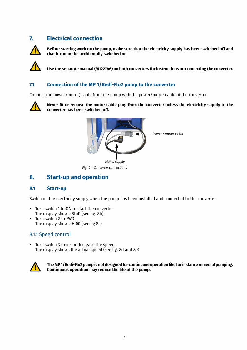
Connect the power (motor) cable from the pump with the power/motor cable of the converter.
Never fit or remove the motor cable plug from the converter unless the electricity supply to the converter has been switched off.
8. Start-up and operation
8.1 Start-up
Switch on the electricity supply when the pump has been installed and connected to the converter.
• Turn switch 1 to ON to start the converterThedisplayshows:StoP(seefig.8b)
• Turn switch 2 to FWDThedisplayshows:H00(seefig8c)
8.1.1 Speed control
• Turn switch 3 to in- or decrease the speed.Thedisplayshowstheactualspeed(seefig.8dand8e)
The MP 1/Redi-Flo2 pump is not designed for continuous operation like for instance remedial pumping. Continuous operation may reduce the life of the pump.
Mains supply
Power/motorcable
Fig. 9 Converter connections
10
8.2 Operation
The MP 1/Redi-Flo2 pump is not designed for continuous operation like for instance remedial pumping. Continuous operation may reduce the life of the pump.
8.2.1 Setting of pump performanceWhen the pump speed has been changed, wait a while to let the speed settle at the set level. Then new adjustments can be made.
8.2.2 MinimumflowTo ensure the necessary cooling of the motor, the pump should never be set so low that it gives no water.Iftheflowratesuddenlyfalls,thereasonmightbethatthepumpispumpingmorewaterthantheboreholecan yield. The pump performance must immediately be reduced or the pump must be stopped to avoid damage to the pump.
8.2.3 After useAfter use, switch off the electricity supply to the converter before the motor cable is disconnected from the converter.
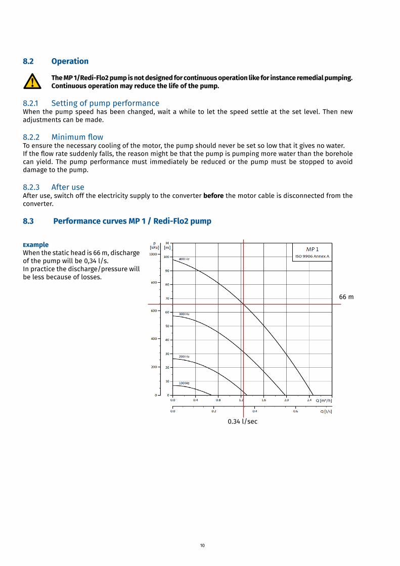
8.3 Performance curves MP 1 / Redi-Flo2 pump
ExampleWhen the static head is 66 m, discharge of the pump will be 0,34 l/s.In practice the discharge/pressure will be less because of losses.
0.34 l/sec
66 m
11
9. Maintenance and service
9.1 Maintenance
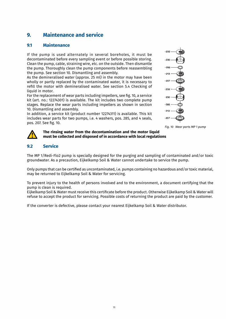
If the pump is used alternately in several boreholes, it must be decontaminated before every sampling event or before possible storing.Clean the pump, cable, straining wire, etc. on the outside. Then dismantle the pump. Thoroughly clean the pump components before reassembling the pump. See section 10. Dismantling and assembly.As the demineralised water (approx. 25 ml) in the motor may have been wholly or partly replaced by the contaminated water, it is necessary to refill themotorwithdemineralisedwater. See section5.4Checkingofliquid in motor.Forthereplacementofwearpartsincludingimpellers,seefig.10,aservicekit (art. no.: 12274301) is available. The kit includes two complete pump stages. Replace the wear parts including impellers as shown in section 10. Dismantling and assembly.In addition, a service kit (product number 12274311) is available. This kit includes wear parts for two pumps, i.e. 4 washers, pos. 285, and 4 seals, pos.207.Seefig.10.
The rinsing water from the decontamination and the motor liquid must be collected and disposed of in accordance with local regulations
9.2 Service
The MP 1/Redi-Flo2 pump is specially designed for the purging and sampling of contaminated and/or toxic groundwater. As a precaution, Eijkelkamp Soil & Water cannot undertake to service the pump.
Onlypumpsthatcanbecertifiedasuncontaminated,i.e.pumpscontainingnohazardousand/ortoxicmaterial,may be returned to Eijkelkamp Soil & Water for servicing.
To prevent injury to the health of persons involved and to the environment, a document certifying that the pump is clean is required.EijkelkampSoil&Watermustreceivethiscertificatebeforetheproduct.OtherwiseEijkelkampSoil&Waterwillrefuse to accept the product for servicing. Possible costs of returning the product are paid by the customer.
If the converter is defective, please contact your nearest Eijkelkamp Soil & Water distributor.
Fig.10 WearpartsMP1pump
12
10. Dismantling and assembly
10.1 Description and overview of the MP 1/Redi-Flo2 sampling pump system
Components
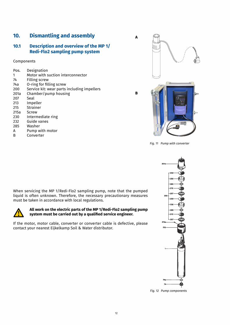
Pos. Designation1 Motor with suction interconnector74 Filling screw74a O-ringforfillingscrew200 Service kit: wear parts including impellers 201a Chamber/pump housing207 Seal213 Impeller215 Strainer215a Screw230 Intermediate ring232 Guide vanes285 WasherA Pump with motorB Converter
When servicing the MP 1/Redi-Flo2 sampling pump, note that the pumped liquid is often unknown. Therefore, the necessary precautionary measures must be taken in accordance with local regulations.
All work on the electric parts of the MP 1/Redi-Flo2 sampling pump system must be carried out by a qualified service engineer.
If the motor, motor cable, converter or converter cable is defective, please contact your nearest Eijkelkamp Soil & Water distributor.
A
B
Fig.11 Pumpwithconverter
Fig. 12 Pump components
13
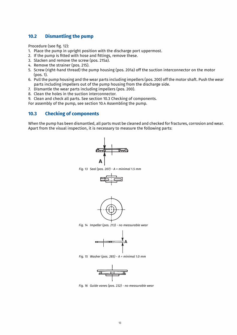
Fig.13 Seal(pos.207)-A=minimal1.5mm
Fig.15 Washer(pos.285)-A=minimal1.0mm
Fig.14 Impeller(pos.213)-nomeasurablewear
Fig.16 Guidevanes(pos.232)-nomeasurablewear
10.2 Dismantling the pump
Procedure(seefig.12):1. Place the pump in upright position with the discharge port uppermost.2. Ifthepumpisfittedwithhoseandfittings,removethese.3. Slacken and remove the screw (pos. 215a).4. Remove the strainer (pos. 215).5. Screw (right-hand thread) the pump housing (pos. 201a) off the suction interconnector on the motor
(pos. 1).6. Pull the pump housing and the wear parts including impellers (pos. 200) off the motor shaft. Push the wear
parts including impellers out of the pump housing from the discharge side.7. Dismantle the wear parts including impellers (pos. 200).8. Clean the holes in the suction interconnector.9. Clean and check all parts. See section 10.3 Checking of components.For assembly of the pump, see section 10.4 Assembling the pump.
10.3 Checking of components
When the pump has been dismantled, all parts must be cleaned and checked for fractures, corrosion and wear.Apart from the visual inspection, it is necessary to measure the following parts:
14
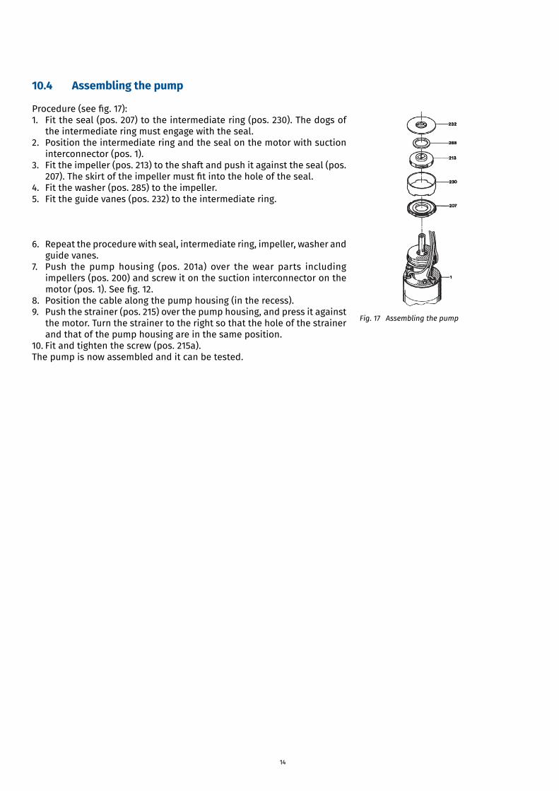
10.4 Assembling the pump
Procedure(seefig.17):1. Fit the seal (pos. 207) to the intermediate ring (pos. 230). The dogs of
the intermediate ring must engage with the seal.2. Position the intermediate ring and the seal on the motor with suction
interconnector (pos. 1).3. Fit the impeller (pos. 213) to the shaft and push it against the seal (pos.
207).Theskirtoftheimpellermustfitintotheholeoftheseal.4. Fit the washer (pos. 285) to the impeller.5. Fit the guide vanes (pos. 232) to the intermediate ring.
6. Repeat the procedure with seal, intermediate ring, impeller, washer and guide vanes.
7. Push the pump housing (pos. 201a) over the wear parts includingimpellers (pos. 200) and screw it on the suction interconnector on themotor(pos.1).Seefig.12.
8. Position the cable along the pump housing (in the recess).9. Push the strainer (pos. 215) over the pump housing, and press it against
the motor. Turn the strainer to the right so that the hole of the strainerand that of the pump housing are in the same position.
10. Fit and tighten the screw (pos. 215a).The pump is now assembled and it can be tested.
Fig.17 Assemblingthepump
15
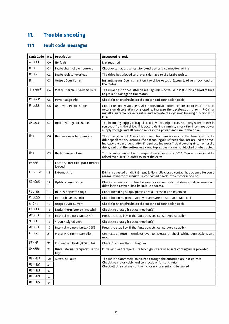
11. Trouble shooting
11.1 Fault code messages
Fault Code No. Description Suggested remedy
no-Flt 00 No fault Not required
OI-b 01 Brake channel over current Check external brake resistor condition and connection wiring
OL-br 02 Brake resistor overload The drive has tripped to prevent damage to the brake resistor
O-I 03 Output Over Current Instantaneous Over current on the drive output. Excess load or shock load on the motor.
I_t-trP 04 Motor Thermal Overload (I2t) The drive has tripped after delivering >100% of value in P-08* for a period of time
to prevent damage to the motor.
PS-trP 05 Power stage trip Check for short circuits on the motor and connection cable
O-volt 06 Over voltage on DC bus Check the supply voltage is within the allowed tolerance for the drive. If the fault occurs on deceleration or stopping, increase the deceleration time in P-04* or install a suitable brake resistor and activate the dynamic braking function with P-34*
U-volt 07 Under voltage on DC bus The incoming supply voltage is too low. This trip occurs routinely when power is removed from the drive. If it occurs during running, check the incoming power supply voltage and all components in the power feed line to the drive.
O-t 08 Heatsink over temperature The drive is too hot. Check the ambient temperature around the drive is within the drivespecification.Ensuresufficientcoolingairisfreetocirculatearoundthedrive.Increasethepanelventilationifrequired.Ensuresufficientcoolingaircanenterthedrive, and that the bottom entry and top exit vents are not blocked or obstructed.
U-t 09 Under temperature Trip occurs when ambient temperature is less than -10°C. Temperature must be raised over -10°C in order to start the drive.
P-dEF 10 Factory Default parameters loaded
E-tr iP 11 External trip E-trip requested on digital input 3. Normally closed contact has opened for some reason. If motor thermistor is connected check if the motor is too hot.
SC-ObS 12 Optibus comms loss Check communication link between drive and external devices. Make sure each drive in the network has its unique address.
FLt-dc 13 DC bus ripple too high Check incoming supply phases are all present and balanced
P-LOSS 14 Input phase loss trip Check incoming power supply phases are present and balanced
h O-I 15 Output Over Current Check for short circuits on the motor and connection cable
th-Flt 16 Faulty thermistor on heatsink Check the analog input connection(s)
dAtA-F 17 Internal memory fault. (IO) Press the stop key. If the fault persists, consult you supplier
4-20F 18 4-20mA Signal Lost Check the analog input connection(s)
dAtA-E 19 Internal memory fault. (DSP) Press the stop key. If the fault persists, consult you supplier
F-Ptc 21 Motor PTC thermistor trip Connected motor thermistor over temperature, check wiring connections and motor
FAn-F 22 Cooling Fan Fault (IP66 only) Check / replace the cooling fan
O-hEAt 23 Drive internal temperature too high
Drive ambient temperature too high, check adequate cooling air is provided
AtF-01 40 Autotune Fault The motor parameters measured through the autotune are not correctCheck the motor cable and connections for continuityCheck all three phases of the motor are present and balancedAtF-02 41
AtF-03 42
AtF-04 43
AtF-05 44

16
SC-FOI 50 Modbus comms loss fault Check the incoming Modbus RTU connection cableCheck that at least one register is being polled cyclically within the timeout limit set in P-36 Index 3*
SC-FO2 51 CANopen comms loss trip Check the incoming CAN connection cableCheck that cyclic communications take place within the timeout limit set in P-36 Index 3*
* See separate manual of the converter
12. DisposalThis product or parts of it must be disposed of in an environmentally sound way:1. Use the public or private waste collection service.2. If this is not possible, contact the nearest Eijkelkamp Soil & Water company/distributor.
17
Supplement to Installation and Operating Instructions
1. Replacement/shortening of motor cableThe submersible drop cable must be complete and without cable joint from the motor to the converter.
Apreviouslyconnectedcablemustbefittedwithanewcablekitbeforeitcanbereused.See3.Shorteningof motor cable.
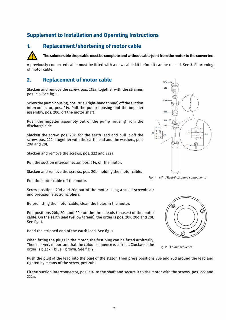
2. Replacement of motor cableSlacken and remove the screw, pos. 215a, together with the strainer, pos.215.Seefig.1.
Screw the pump housing, pos. 201a, (right-hand thread) off the suction interconnector, pos. 214. Pull the pump housing and the impeller assembly, pos. 200, off the motor shaft.
Push the impeller assembly out of the pump housing from the discharge side.
Slacken the screw, pos. 20k, for the earth lead and pull it off the screw, pos. 222a, together with the earth lead and the washers, pos. 20d and 20f.
Slacken and remove the screws, pos. 222 and 222a
Pull the suction interconnector, pos. 214, off the motor.
Slacken and remove the screws, pos. 20b, holding the motor cable.
Pull the motor cable off the motor.
Screw positions 20d and 20e out of the motor using a small screwdriver and precision electronic pliers.
Beforefittingthemotorcable,cleantheholesinthemotor.
Pull positions 20b, 20d and 20e on the three leads (phases) of the motor cable. On the earth lead (yellow/green), the order is pos. 20k, 20d and 20f. Seefig.1.
Bendthestrippedendoftheearthlead.Seefig.1.
Whenfittingtheplugsinthemotor,thefirstplugcanbefittedarbitrarily.Then it is very important that the colour sequence is correct. Clockwise the orderisblack-blue-brown.Seefig.2.
Push the plug of the lead into the plug of the stator. Then press positions 20e and 20d around the lead and tighten by means of the screw, pos 20b.
Fit the suction interconnector, pos. 214, to the shaft and secure it to the motor with the screws, pos. 222 and 222a.
Fig. 1 MP 1/Redi-Flo2 pump components
Fig. 2 Colour sequence
18
Position the washer pos. 20g, on the screw, pos. 222a. Hold the earth lead against the washer while the screw, pos. 20k, is tightened.
Position the cable along the pump housing (in the recess). Push the strainer, pos. 215, over the pump housing and press it against the motor. Turn the strainer to the right so that the hole of the strainer and that of the pump housing are in the same position. Fit and tighten the screw, pos. 215a.
Check the direction of rotation, see 3.2 Checking of direction of rotation
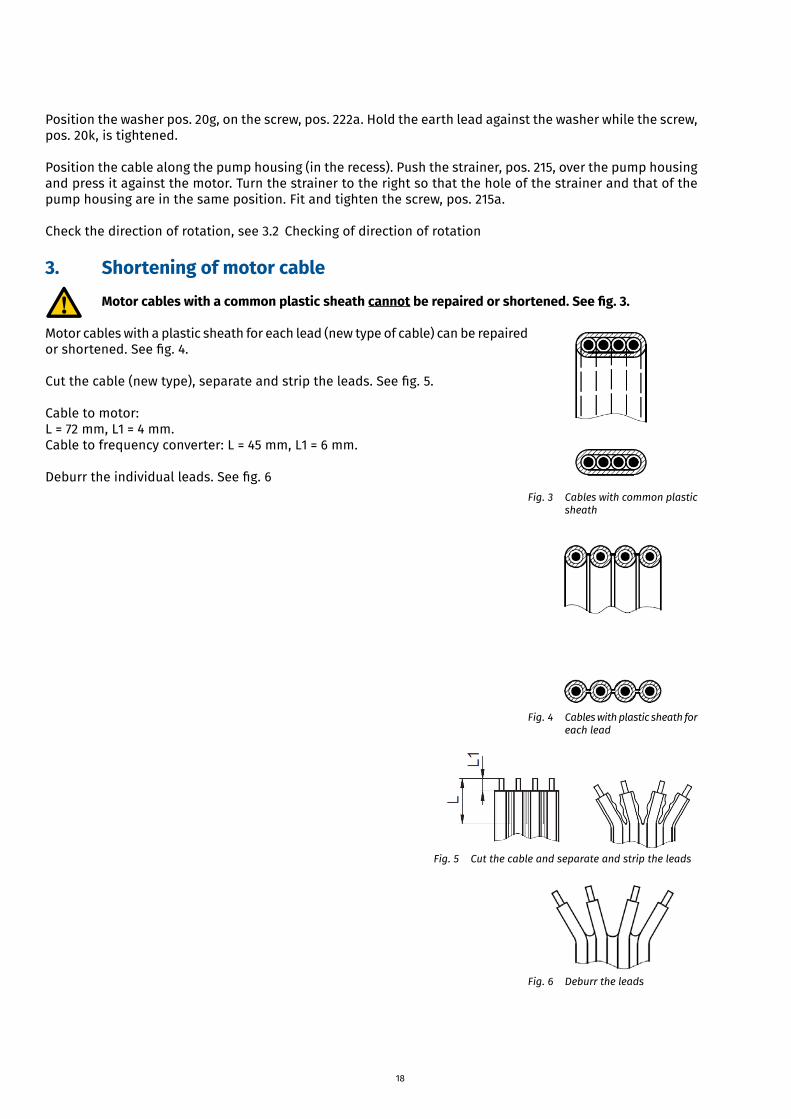
3. Shortening of motor cableMotor cables with a common plastic sheath cannot be repaired or shortened. See fig. 3.
Motor cables with a plastic sheath for each lead (new type of cable) can be repaired orshortened.Seefig.4.
Cutthecable(newtype),separateandstriptheleads.Seefig.5.
Cable to motor:L = 72 mm, L1 = 4 mm.Cable to frequency converter: L = 45 mm, L1 = 6 mm.
Deburrtheindividualleads.Seefig.6Fig.3 Cableswithcommonplastic
sheath
Fig.4 Cableswithplasticsheathfor each lead
Fig. 5 Cut the cable and separate and strip the leads
Fig.6 Deburrtheleads
19
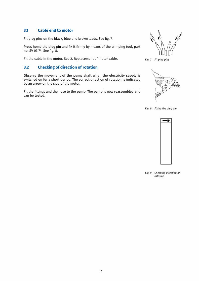
3.1 Cable end to motor
Fitplugpinsontheblack,blueandbrownleads.Seefig.7.
Presshometheplugpinandfixitfirmlybymeansofthecrimpingtool,partno.SV0374.Seefig.8.
Fit the cable in the motor. See 2. Replacement of motor cable.
3.2 Checking of direction of rotation
Observe the movement of the pump shaft when the electricity supply is switched on for a short period. The correct direction of rotation is indicated by an arrow on the side of the motor.
Fitthefittingsandthehosetothepump.Thepumpisnowreassembledandcan be tested.
Fig. 7 Fit plug pins
Fig. 8 Fixing the plug pin
Fig. 9 Checking direction of rotation