Embed Size (px)
Citation preview
GRUNDFOS PRODUCT GUIDE
Sanitary pumpsFB
Centrifugal pumps60 Hz
FB-Hygia.book Page 1 Monday, June 21, 2010 4:58 PM

Contents
2
MissionMission 3
IntroductionGrundfos sanitary pumps 4Hygienic design 4
Performance rangeFB, 2-pole 5FB, 4-pole 5
Product dataTechnical data 6Applications 6Features and benefits 6Construction 6Pump housing 7Impeller 7Connections 7Surface finish 7Mechanical shaft seals 7Motor 8Design variations 8
CertificationApprovals and certificates 9Certificates 9
IdentificationType key 10
InstallationMechanical installation 11Space requirements 11Elimination of noise and vibration 11
Curve chartsHow to read the pump curves 12Curve conditions 13
Performance curvesFB 10/40, 2-pole 14FB 10/40, 4-pole 15FB 20/25, 2-pole 16FB 20/25, 4-pole 17FB 15/40, 2-pole 18FB 15/40, 4-pole 19FB 25/15, 2-pole 20FB 25/15, 4-pole 21FB 30/60, 2-pole 22FB 30/60, 4-pole 23FB 70/40, 2-pole 24FB 70/40, 4-pole 25FB 20/65, 2-pole 26FB 20/65, 4-pole 27FB 80/30, 2-pole 28FB 80/30, 4-pole 29FB 25/60, 2-pole 30FB 25/60, 4-pole 31FB 120/30, 2-pole 32FB 120/30, 4-pole 33
DimensionsFB pump on foot-mounted motor 34FB pump on foot-mounted motor 35FB pump with feet and support bars 36FB pump with feet and support bars 37
FB-Hygia.book Page 2 Monday, June 21, 2010 4:58 PM

Sanitary pumpsFB
3
Mission
Mission- It is our mission - the basis of our existence - to successfully develop, produce and sell high-quality pumps and pumping systems world-wide, contributing to a better quality of life and a healthy environment
• One of the 3 largest pump companies in the world• The second largest manufacturer of submersible motors in the world• World headquarters in Denmark• North American headquarters in Kansas City - Manufacturing in Fresno, California• 82 companies in 45 countries• More than 16 million motors and pumps produced annually worldwide• North American companies operating in USA, Canada and Mexico• Continuous reinvestment in growth and development enables the company to
BE responsible, THINK ahead, and INNOVATE
Bjerringbro, Denmark
Fresno, California Olathe, Kansas
Monterrey, Mexico Allentown, Pennsylvania Oakville, Ontario
FB-Hygia.book Page 3 Monday, June 21, 2010 4:58 PM

Sanitary pumpsFB
4
Introduction
Grundfos sanitary pumpsStainless steel sanitary pumps designed for a wide range of hygienic and sanitary applications such as:
• food and beverage• life science/pharmaceutical• personal care• water treatment.
The Grundfos range of sanitary pumps is comprised of a range of single- and multi-stage end-suctioncentrifugal pumps and side-channel, self-priming pumps, each state-of-the-art within its specific field of application.
The pumps can be fitted with a variety of features to adapt to specific pumping tasks. In addition, it ispossible to customize the pumps for optimum function or performance in relation to the job at hand.
FB
Single-stage, end-suction centrifugal pumps. The pumps offer heads up to 279 ft, flow rates up to 418 US GPM and operating pressures up to 232 PSI. Pipeconnections range from 1.5 inch to 4 inch and motor sizes from 1.0 to 25 Hp.
Hygienic designThe Grundfos sanitary pumps have been designed in accordance with the strictest hygienic design criteria.
The surface finish of the materials used is of paramount importance to prevent possible breeding grounds for bacteria and to facilitate efficient and thorough cleaning using CIP (Cleaning-In-Place) processes.
Fully drainable models are available, and the use of AISI 316L (DIN EN 1.4404/1.4435) cold-rolled and/or forged stainless steel ensures a homogeneous,pore-free surface in contrast to cast materials.
The design, materials and material surface finish are subject to a variety of national and international rules and regulations, guidelines and laws. Among these are the EU Machinery Directive, the GMP (GoodManufacturing Practices) rules and regulations, the FDA (Food and Drug Administration) regulations, the 3A Sanitary Standards, the EU foodstuff hygienic guidelines, the DIN EN 12462 Biotechnology Standard as well as the EHEDG (European Hygienic Engineering & Design Group) and the QHD (Qualified Hygienic Design) criteria.
Mechanical shaft sealsSingle-seal and quenched seal arrangements areavailable as required for the application and the pumped liquid. The seals offer trouble-free operation.
ConnectionsA variety of connections are available, such as Tri-Clamp to DIN 32676, female NPT and ANSI 150lb flanges.
FB-Hygia.book Page 4 Monday, June 21, 2010 4:58 PM

Sanitary pumpsFB
5
Performance range
FB, 2-pole
FB, 4-pole
TM04
492
2 22
09
10 15 20 30 40 50 60 80 100 150 200 300 400 500 600 800Q [US GPM]
40
60
80
100
120
140
160
180
200
220
240
260
280
300
320
340
360[ft]H
3 4 5 6 7 8 9 1010 20 30 40 50 60 70 80 100100 Q [m³/h]
20
30
40
50
60
70
80
90
100
110[m]H
FB3500 rpm
25/15
20/25
15/4010/40
120/30
80/30
70/40
30/60
25/60
20/65
TM04
492
3 22
09
10 15 20 30 40 50 60 80 100 150 200 300 400 500 600 800Q [US GPM]
10
20
30
40
50
60
70
80
90
[ft]H
3 4 5 6 7 8 9 1010 20 30 40 50 60 70 80 100100 Q [m³/h]
5
10
15
20
25
[m]H
FB1750 rpm
25/15
20/25
15/40
10/40
120/30
80/30
70/40
20/65
25/60
30/60
FB-Hygia.book Page 5 Monday, June 21, 2010 4:58 PM

6
FB-Hygia.book Page 6 Monday, June 21, 2010 4:58 PM
Sanitary pumpsProduct data
Fig. 1 FB
Technical data
ApplicationsThe unique hygienic design and the materials used make the FB pump range suitable for these applica-tions:
• BeveragesBeer, soft drinks, alcohol, wine, fruit drinks, yeast, etc.
• DairiesMilk, whey, cream, condensed milk, etc.
• ConfectionerySyrup, sugar solutions, etc.
• Meat packingLiquid fat, frying oil, smokehouse spray, blood processing, etc.
Features and benefits• Support options for motor and pump for flexible
installation meeting 3-A requirements.• Extremely reliable operation under most working
conditions for low maintenance cost; use same pump in variety of applications.
• Optimized hydraulics for high efficiency and reduced power consumption.
• Semi-closed impeller design for increased suitability for applications involving low-viscosity liquids and liquids containing particles.
ConstructionFB pumps are single-stage, end-suction centrifugal pumps, designed to meet the hygienic requirements of sterile process technology.
The pumps are CIP and SIP capable in compliance with the DIN EN 12462 performance criteria.
The design of the wetted parts complies with:
• QHD criteria• EHEDG recommendations for CIP cleanability (vali-
dated by the TNO Quality of Life institute)• 3A Sanitary Standards (3A 02-10).For explanation, see Certificates, page 9.
Fig. 2 Certification
Materials
Fig. 3 Sectional drawing of FB pump
TM04
502
8 24
09
Head: up to 350 ftFlow rate: up to 675 US GPMOperating pressure: up to 232 PSIOperating temperature: up to 203 °F
(up to 302 °F on request)Sterilization temperature: 284 °F (SIP)
(Sterilization-In-Place).
A-3
TM04
503
7 25
09
Pos. Component Material DIN/EN AISI/ASTM
1 Impeller CrNiMo steel 1.4404 316L2 Pump housing CrNiMo steel 1.4404 316L
3 Shaft seal
Seal faces: Carbon/stainless steelor SiC/SiC
O-rings: EPDM or FKM4 Pump shaft CrNiMo steel 1.4571 316Ti5 Motor
6 Feet andsupport bars Stainless steel
Product data Sanitary pumpsFB
FB-Hygia.book Page 7 Monday, June 21, 2010 4:58 PM
Pump housing
The pump housing is made of heavy-duty, rolled and deep-drawn CrNiMo steel to DIN EN 1.4404, the equivalent of AISI 316L.
ImpellerFB pumps feature a cast stainless steel, semi-closed impeller.
Fig. 4 Semi-closed impeller
ConnectionsStandard connections• Clamps for Tri-Clamp®.
Connections on request• ANSI 150lb flanges• Internal NPT thread.
Surface finishIn order to meet the demands of the pharmaceutical, food and beverage industries, all contact surfaces of the product have a surface finish of < 0.8µ Ra.
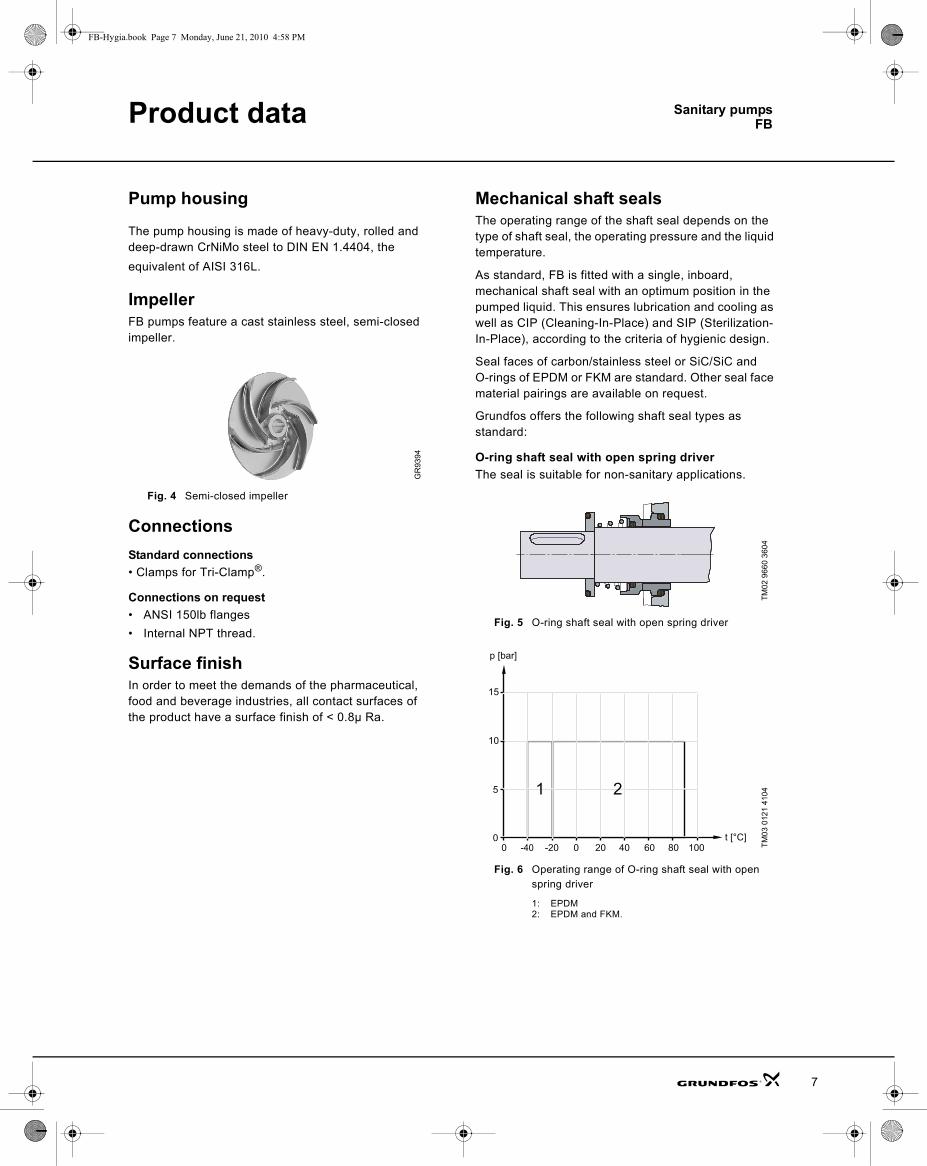
Mechanical shaft sealsThe operating range of the shaft seal depends on the type of shaft seal, the operating pressure and the liquid temperature.
As standard, FB is fitted with a single, inboard,mechanical shaft seal with an optimum position in the pumped liquid. This ensures lubrication and cooling as well as CIP (Cleaning-In-Place) and SIP (Sterilization-In-Place), according to the criteria of hygienic design.
Seal faces of carbon/stainless steel or SiC/SiC and O-rings of EPDM or FKM are standard. Other seal face material pairings are available on request.
Grundfos offers the following shaft seal types asstandard:
O-ring shaft seal with open spring driverThe seal is suitable for non-sanitary applications.
Fig. 5 O-ring shaft seal with open spring driver
Fig. 6 Operating range of O-ring shaft seal with open spring driver
1: EPDM2: EPDM and FKM.
GR
9394
TM02
966
0 36
04TM
03 0
121
4104
0 -40 -20 0 20 40 60 80 1000
15
5
10
t [°C]
p [bar]
1 2
7

Product data Sanitary pumps
8
FB-Hygia.book Page 8 Monday, June 21, 2010 4:58 PM
O-ring shaft seal with enclosed springThe seal is suitable for hygienic applications or those requiring compliance with 3-A Sanitary Standards.
Fig. 7 O-ring shaft seal with enclosed spring
Fig. 8 Operating range of O-ring shaft seal with en-closed spring
1: EPDM2: EPDM and FKM.
Quench sealAll shaft seal types are available in quench design.
MotorThe standard motor is a totally enclosed, fan-cooled Baldor “Washdown Duty” motor.
Options for non-washdown duty types, “Premium Effi-ciency”, “Stainless Steel” and alternative voltages are available.
Design variationsGrundfos offers FB models with or without feet and sup-port bars. FB feet comply with current 3-A sanitary standards.
Fig. 9 FB on foot-mounted motor
Fig. 10 FB with stainless steel feet and support bars
TM02
966
4 36
04TM
04 5
097
2609
1 2
00 -40 -20 0 20 40 60 80 100
5
10
15
20
25
30
t [°C]
p [bar] TM04
503
5 25
09TM
04 5
036
2509

Sanitary pumpsFB
9
Certification
Approvals and certificatesThe design, materials used and surface finish are sub-ject to a variety of national and international rules and regulations, such as the 3A Sanitary Standards, the EHEDG recommendations and the QHD criteria.
3A Sanitary Standards
Fig. 11 3A symbol
The 3A Sanitary Standards for design and manufacture provide material specifications and requirements for surface finish.
This ensures that dairy, food and other microbially sen-sitive products are protected from contamination and that all surfaces in contact with the products can be cleaned in place (CIP) or easily dismantled for manual cleaning.
The 3A symbol is used by manufacturers to indicate compliance with the 3A Sanitary Standards.
CertificatesGrundfos offers the following certificates and approvals for the FB models:
• Hygienic design certificates.Certifies compliance with the 3A Sanitary Stand-ards.
• Performance certificates.Test reports guaranteeing and certifying QH test data, power consumption, speed, curves, etc.)are available upon request.
A3
TM03
009
1 39
04Certificate Standard3A hygienic design certificate 3A 02-10Standard test report ISO 9906
Initially Issued: 3/31/2009 Authorization No.: 1505
This Is To Certify That
Grundfos Pumps Mfg. Corp. 5900 E. Shields Ave., Fresno, CA 93727
Is hereby authorized to continue to apply the 3-A Symbol to the models of equipment, conforming to 3-A Sanitary Standards for:
Centrifugal and Positive Rotary Pumps, Number: 02-10, set forth below:
Model Designations: FB 10/40 thru FB 120/30 in a series design in pipe sizes 1.5, 2, 2.5, 3 and 4 inches.
Valid through: December 31, 2009
Timothy R. Rugh_______________________ Executive Director, 3-A Sanitary Standards, Inc.
***** The issuance of this authorization for the use of the 3-A Symbol is based upon the voluntary certification, by the applicant for it, that the equipment listed above complies fully with the 3-A Sanitary Standards designated. Legal responsibility for compliance is solely that of the holder of this Certificate of Authorization, and 3-A Sanitary Standards, Inc. does not warrant that the holder of an authorization at all times complies with the provisions of the said 3-A Sanitary Standards. This in no way affects the responsibility of 3-A Sanitary Standards, Inc. to take appropriate action in such cases in which evidence of nonconformance has been established.
R
FB-Hygia.book Page 9 Monday, June 21, 2010 4:58 PM

Sanitary pumpsFB
10
Identification
Type key
FB20/25-130-ACAE-ASCE-FY-1.5-4US
Pum
p ra
nge
Mod
el n
ame
Impe
ller
diam
eter
(mm
)
Phys
ical
var
iatio
ns
Con
nect
ion
type
Mat
eria
ls
Elas
tom
er
Type
Rot
atin
g fa
ce m
ater
ial
Stat
iona
ry s
eat m
ater
ial
Elas
tom
er
Leg
/ fee
t
3-A
Hp
Pole
s
volta
ge
Dut
y
FB20/25-130-ACAE-ASCE-FY-1.5-4US FB 20/25 130 A C A E A S C E F Y 1.5 4 U S10/40; 20/25; 15/40;25/1530/60;70/40; 20/65; 80/30; 25/60;120/30130; 140; 150; 150x6; 150x12; 155; 160; 165; 170; 175; 180; 185x6; 185x9; 190; 200; 210; 220; 230x12; 230x18Basic version(standard volute with 12 o'clock discharge orientation and 3-A surface finish) A
Special version(e.g. non-standard discharge orientation, surface finish, drain port, cart mounting, etc.) X
Tri-Clamp CInternal NPT thread SANSI flange GOther connections available on request. XStandard material (1.4404 stainless steel 316L) ASpecial material XEPDM EFKM VO-ring seal with enclosed spring (enclosed spring seal required for 3-A compliance) AO-ring seal with open spring driver (for non-sanitary applications) CQuench O-ring seal with enclosed spring (enclosed spring seal required for 3-A compliance) QQuench O-ring seal with open spring driver (for non-sanitary applications) RStainless steel SSilicon carbide QCarbon CSilicon carbide QEPDM EFKM VStainless steel leg and foot assembly (3-A compliant) FNo feet XComplies with 3-A and carries label YNo 3-A label N1; 1.5; 2; 3; 5; 7.5; 10; 15; 20; 252; 4230/460 (USA) U575 volt (Canada) COther (e.g. 115 V 1-phase) XBaldor Super E Washdown (25 Hp has finned body) (CEWDM) EBaldor Premium Efficient (CEM) PStainless steel motor SOther motors available on request X
Other seal face materials available upon request.
Other seal face materials available upon request.
FB-Hygia.book Page 10 Monday, June 21, 2010 4:58 PM

Sanitary pumpsFB
11
Installation
Mechanical installationThe pump should never be installed with the motor below the pump.
Fig. 12 Installation
The pumps must be installed in such a way that strain from the pipework is not transferred to the pumphousing.
Space requirementsVertical installation• Pumps fitted with motors up to and including 5 Hp
require a 12“ clearance above the motor. Consult the motor manufacturer’s instructions for details.
• Pumps fitted with motors of 7.5 Hp and up require at least a 3-feet clearance above the motor to allow the use of lifting equipment. Consult the motormanufacturer’s instructions for details.
Fig. 13 Vertical installation
Horizontal installation• Pumps fitted with motors up to and including 5 Hp
require a 12" clearance behind the motor. Consult the motor manufacturer’s instructions for details.
• Pumps fitted with motors of 7.5 Hp and up require a 12 “ clearance behind and a 3 ft clearance above the motor to allow the use of lifting equipment.Consult the motor manufacturer’s instructions for details.
Fig. 14 Horizontal installation
Elimination of noise and vibrationIn order to achieve optimum operation with minimum noise and vibration, consider vibration dampening of the pump. This is most important for pumps with motors above 15 Hp. Smaller pumps may also causeundesirable noise and vibration.
Noise and vibration are generated by the rotation in the motor and pump, by the flow in pipes and fittings and other equipment connected in the same or adjacent processes. The effect on the environment is subjective and depends on correct installation and the system design.
The pipes should be anchored so that they do not stress the expansion joints and the pump. Follow the supplier’s instructions and pass them on to advisers or pipe installers.
TM04
419
8 10
09TM
03 0
114
4004
7.5-40 Hp0.75-5 Hp
12" 3 ft
TM03
011
5 40
04
12“
3 ft
7.5-40 Hp
12“
0.75-5 Hp
FB-Hygia.book Page 11 Monday, June 21, 2010 4:58 PM

12
FB-Hygia.book Page 12 Monday, June 21, 2010 4:58 PM
Sanitary pumpsFBCurve charts
How to read the pump curves
TM04
492
1 22
09
0 10 20 30 40 50 60 70 80 90 100 Q [US GPM]
0
4
8
12
16
20
24
28
32
36
[ft]H
0
2
4
6
8
10
[m]H
0
2
4
[ft]NPSH
0.0
0.5
1.0
[m]
FB 25/151750 rpm
ISO 9906 Annex A
130
160
130
140
150
16031 %
34 %37 %
40 %
43 %
43 %
40 %
37 %
34 %
31 %
38.0 %
40.4 %
42.6 %
44.9 %
0 10 20 30 40 50 60 70 80 90 100 Q [US GPM]
0.0
0.2
0.4
0.6
0.8
1.0
[hp]P2
0 5 10 15 20 25 Q [m³/h]
0.0
0.2
0.4
0.6
[kW]P2
130
140
150
160
Pump type and speed of rotation.
QH curve for the individual pump with a specific impeller diameter.
The power curve indicates pump input power [P2] for the individual pump with a specific impeller diameter.
The hydraulic efficiency curves are shown as dashed lines
The NPSH curve indicates the Net Positive Suction Head of the individual pump with a specific impeller diameter.
Curve charts Sanitary pumpsFB
FB-Hygia.book Page 13 Monday, June 21, 2010 4:58 PM
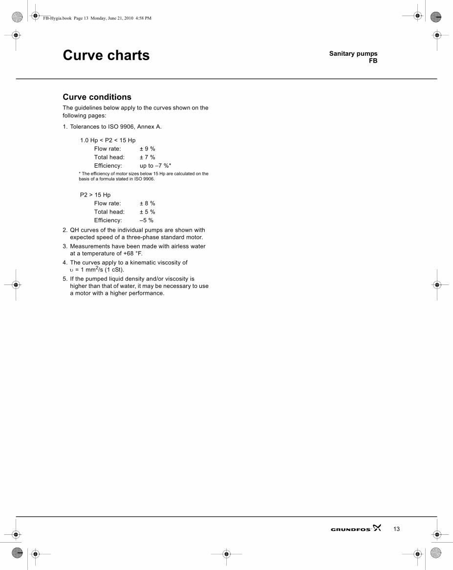
Curve conditionsThe guidelines below apply to the curves shown on the following pages:
1. Tolerances to ISO 9906, Annex A.
2. QH curves of the individual pumps are shown with expected speed of a three-phase standard motor.
3. Measurements have been made with airless water at a temperature of +68 °F.
4. The curves apply to a kinematic viscosity of υ = 1 mm2/s (1 cSt).
5. If the pumped liquid density and/or viscosity is higher than that of water, it may be necessary to use a motor with a higher performance.
1.0 Hp < P2 < 15 HpFlow rate: ± 9 %Total head: ± 7 %Efficiency: up to –7 %*
* The efficiency of motor sizes below 15 Hp are calculated on the basis of a formula stated in ISO 9906.
P2 > 15 HpFlow rate: ± 8 %Total head: ± 5 %Efficiency: –5 %
13

14
FB-Hygia.book Page 14 Monday, June 21, 2010 4:58 PM
Performance curves
FB 10/40, 1 1/2” x 1 1/2”, 2-pole
TM04
451
9 22
09
0 10 20 30 40 50 60 70 80 90 100 110 120 130 Q [US GPM]
0
20
40
60
80
100
120
140
160
180
200
220
240
[ft]H
0
10
20
30
40
50
60
70
[m]H
0
4
8
12
[ft]NPSH
0
1
2
3
[m]
FB 10/403500 rpm
ISO 9906 Annex A
155
185-6
185-9
155
165
175
185-6
185-9
55.2 %
57.5 %
57.8 %
59.1 %
46.2 %30 % 35 % 40 %
47 % 50 % 53 %
56 %
58 %
58 %
0 10 20 30 40 50 60 70 80 90 100 110 120 130 Q [US GPM]
0
2
4
6
8
10
[hp]P2
0 5 10 15 20 25 30 Q [m³/h]
0
2
4
6
[kW]P2
155165175185-6
185-9
FB 10/401 1/2” x 1 1/2”2-pole, 60 Hz

Performance curves FB 10/401 1/2” x 1 1/2”4-pole, 60 Hz
FB-Hygia.book Page 15 Monday, June 21, 2010 4:58 PM
FB 10/40, 1 1/2” x 1 1/2”, 4-pole
TM04
452
0 22
09
0 10 20 30 40 50 60 70 80 90 Q [US GPM]
0
5
10
15
20
25
30
35
40
45
50
55
[ft]H
0
2
4
6
8
10
12
14
16
[m]H
0
4
8
[ft]NPSH
0
1
2
[m]
FB 10/401750 rpm
ISO 9906 Annex A
155 185-6
185-9
155
165
175
185-6
185-9
56.5 %
55.1 %
52.9 %
50.8 %
48.8 %
45 %48 %
51 %54 %
54 %
48 %
51 %
45 %
0 10 20 30 40 50 60 70 80 90 Q [US GPM]
0.0
0.4
0.8
1.2
1.6
2.0
[hp]P2
0 5 10 15 20 Q [m³/h]
0.0
0.4
0.8
1.2
[kW]P2
155
165
175
185-6
185-9
15

Performance curves
16
FB 20/251 1/2” x 1 1/2”2-pole, 60 Hz
FB-Hygia.book Page 16 Monday, June 21, 2010 4:58 PM
FB 20/25, 1 1/2” x 1 1/2”, 2-pole
TM04
452
3 22
09
0 10 20 30 40 50 60 70 80 90 100 110 120 Q [US GPM]
0
10
20
30
40
50
60
70
80
90
100
110
120
130
[ft]H
0
5
10
15
20
25
30
35
40[m]H
0
5
10
[ft]NPSH
0
1
2
3
[m]
FB 20/253500 rpm
ISO 9906 Annex A
130
160
130
140
150
16043 % 46 %
49 %
52 %
52 %
49 %
46 %
48.1 %
50.2 %
52.1 %
54.0 %
0 10 20 30 40 50 60 70 80 90 100 110 120 Q [US GPM]
0
1
2
3
4
5
[hp]P2
0 5 10 15 20 25 30Q [m³/h]
0
1
2
3
[kW]P2
130
140
150
160

Performance curves FB 20/251 1/2” x 1 1/2”4-pole, 60 Hz
FB-Hygia.book Page 17 Monday, June 21, 2010 4:58 PM
FB 20/25, 1 1/2” x 1 1/2”, 4-pole
TM04
491
9 22
09
0 5 10 15 20 25 30 35 40 45 50 55 60 65 Q [US GPM]
0
4
8
12
16
20
24
28
32
36
[ft]H
0
2
4
6
8
10
[m]H
0
4
8
[ft]NPSH
0
1
2
[m]
FB 20/251750 rpm
ISO 9906 Annex A
130
160
130
140
150
160 27 % 30 %33 %
37 %
40 %
40 %
37 %
33 %
30 %27 %
30.7 %
34.0 %
37.5 %
41.2 %
0 5 10 15 20 25 30 35 40 45 50 55 60 65 Q [US GPM]
0.0
0.2
0.4
0.6
0.8
[hp]P2
0 2 4 6 8 10 12 14 16Q [m³/h]
0.0
0.2
0.4
0.6
[kW]P2
130140
150160
17
Performance curves
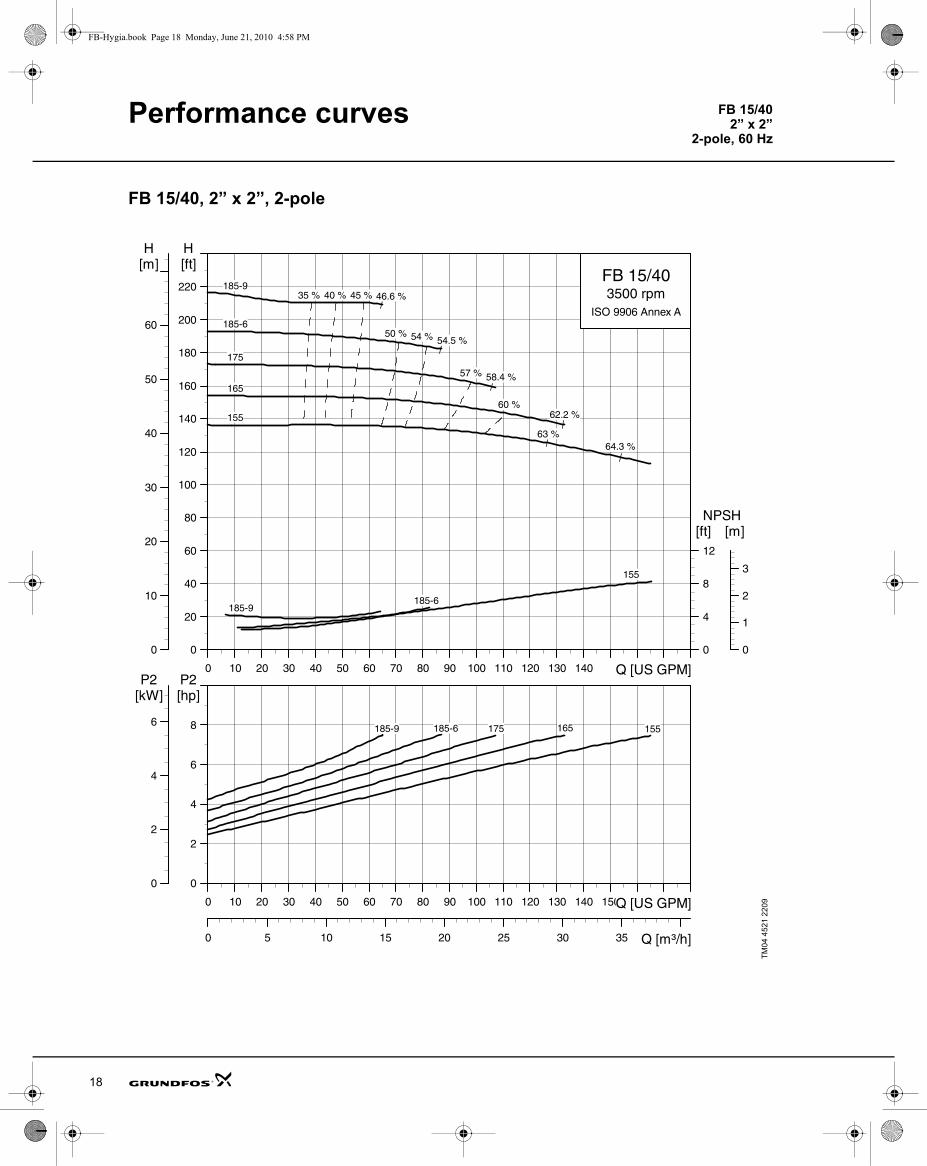
18
FB 15/402” x 2”
2-pole, 60 Hz
FB-Hygia.book Page 18 Monday, June 21, 2010 4:58 PM
FB 15/40, 2” x 2”, 2-pole
TM04
452
1 22
09
0 10 20 30 40 50 60 70 80 90 100 110 120 130 140 Q [US GPM]
0
20
40
60
80
100
120
140
160
180
200
220
[ft]H
0
10
20
30
40
50
60
[m]H
0
4
8
12
[ft]NPSH
0
1
2
3
[m]
FB 15/403500 rpm
ISO 9906 Annex A
155
185-6185-9
155
165
175
185-6
185-9
63 %64.3 %
62.2 %
58.4 %
54.5 %
57 %
54 %
46.6 %
50 %
45 %40 %35 %
60 %
0 10 20 30 40 50 60 70 80 90 100 110 120 130 140 150Q [US GPM]
0
2
4
6
8
[hp]P2
0 5 10 15 20 25 30 35 Q [m³/h]
0
2
4
6
[kW]P2
155165175185-6185-9

Performance curves FB 15/402” x 2”
4-pole, 60 Hz
FB-Hygia.book Page 19 Monday, June 21, 2010 4:58 PM
FB 15/40, 2” x 2”, 4-pole
TM04
452
2 22
09
0 20 40 60 80 100 120 140 160 180 Q [US GPM]
0
5
10
15
20
25
30
35
40
45
50
55
[ft]H
0
2
4
6
8
10
12
14
16
[m]H
0
10
20
[ft]NPSH
0
2
4
6
[m]
FB 15/401750 rpm
ISO 9906 Annex A
155185-6
185-9
155
165
175
185-6
185-9
53.3 %53.8 %54.4 %
55.2 %
45 %
50 %
53 %
53 %
50 %
45 %
50 %
53 %
57 %
60 %
61.0 %
60 %
57 %53 %
50 %
0 20 40 60 80 100 120 140 160 180 Q [US GPM]
0.0
0.5
1.0
1.5
2.0
2.5
[hp]P2
0 5 10 15 20 25 30 35 40 Q [m³/h]
0.0
0.5
1.0
1.5
[kW]P2
155
165175
185-6
185-9
19

Performance curves
20
FB 25/152” x 2”
2-pole, 60 Hz
FB-Hygia.book Page 20 Monday, June 21, 2010 4:58 PM
FB 25/15, 2” x 2”, 2-pole
TM04
492
0 22
09
0 20 40 60 80 100 120 140 160 180 Q [US GPM]
0
10
20
30
40
50
60
70
80
90
100
110
120
130
[ft]H
0
5
10
15
20
25
30
35
40[m]H
0
5
10
15
[ft]NPSH
0
1
2
3
4
[m]
FB 25/153500 rpm
ISO 9906 Annex A
130
160
130
140
150
160
47 %
50 %
53 %
56 %
56 %
53 %
57.9 %
56.4 %
54.9 %
53.3 %
50 %47 %
0 20 40 60 80 100 120 140 160 180 Q [US GPM]
0
1
2
3
4
5
6
[hp]P2
0 5 10 15 20 25 30 35 40 45 Q [m³/h]
0
1
2
3
4
[kW]P2
130
140
150
160

Performance curves FB 25/152” x 2”
4-pole, 60 Hz
FB-Hygia.book Page 21 Monday, June 21, 2010 4:58 PM
FB 25/15, 2” x 2”, 4-pole
TM04
492
1 22
09
0 10 20 30 40 50 60 70 80 90 100 Q [US GPM]
0
4
8
12
16
20
24
28
32
36
[ft]H
0
2
4
6
8
10
[m]H
0
2
4
[ft]NPSH
0.0
0.5
1.0
[m]
FB 25/151750 rpm
ISO 9906 Annex A
130
160
130
140
150
16031 %
34 %37 %
40 %
43 %
43 %
40 %
37 %
34 %
31 %
38.0 %
40.4 %
42.6 %
44.9 %
0 10 20 30 40 50 60 70 80 90 100 Q [US GPM]
0.0
0.2
0.4
0.6
0.8
1.0
[hp]P2
0 5 10 15 20 25 Q [m³/h]
0.0
0.2
0.4
0.6
[kW]P2
130
140
150
160
21

Performance curves
22
FB 30-602 1/2” x 2 1/2”2-pole, 60 Hz
FB-Hygia.book Page 22 Monday, June 21, 2010 4:58 PM
FB 30/60, 2 1/2” x 2 1/2”, 2-pole
TM04
451
1 22
09
0 20 40 60 80 100 120 140 160 180 200 220 240 Q [US GPM]
0
40
80
120
160
200
240
280
320
360
[ft]H
0
20
40
60
80
100
[m]H
2
4
6
8
[ft]NPSH
1.0
1.5
2.0
[m]
FB 30/60
3500 rpm
ISO 9906 Annex A
190
230-12
230-18
190
200
210
220
230-12
230-1830 % 35 %
40 % 45 % 50 %
55 %
60 %
39.5 %
51.8 %
54.0 %
56.3 %
58.9 %
61.7 %
0 20 40 60 80 100 120 140 160 180 200 220 240 Q [US GPM]
0
5
10
15
20
25
30
[hp]P2
0 10 20 30 40 50 60Q [m³/h]
0
5
10
15
20
[kW]P2
190200210220230-12230-18

Performance curves FB 30/602 1/2” x 2 1/2”4-pole, 60 Hz
FB-Hygia.book Page 23 Monday, June 21, 2010 4:58 PM
FB 30/60, 2 1/2” x 2 1/2”, 4-pole
TM04
451
2 22
09
0 40 80 120 160 200 240 280 320 360 Q [US GPM]
0
10
20
30
40
50
60
70
80
90
[ft]H
0
5
10
15
20
25
[m]H
0
10
20
30
[ft]NPSH
0
2
4
6
8
[m]
FB 30/601750 rpm
ISO 9906 Annex A
190220230-12
230-18
190
200
210
220
230-12
230-18
73.8 %
64.5 %
57 % 61 %65 %
68 %
57 %
61 %
65 %
68 %
62.0 %
67.9 %
70.9 %
68.7 %
0 40 80 120 160 200 240 280 320 360 Q [US GPM]
0
2
4
6
8
10
[hp]P2
0 20 40 60 80 Q [m³/h]
0
2
4
6
[kW]P2
190200
210220
230-12
230-18
23
Performance curves
24
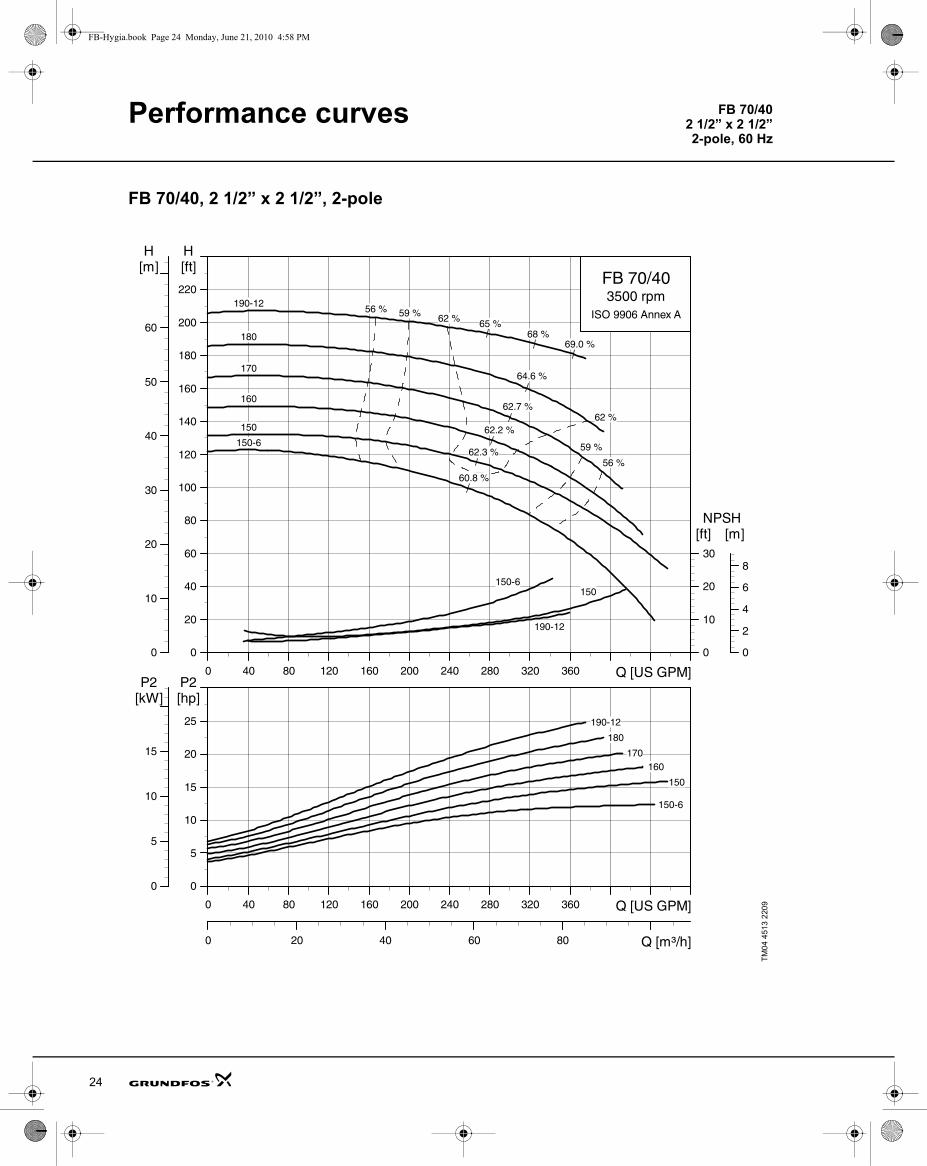
FB 70/402 1/2” x 2 1/2”2-pole, 60 Hz
FB-Hygia.book Page 24 Monday, June 21, 2010 4:58 PM
FB 70/40, 2 1/2” x 2 1/2”, 2-pole
TM04
451
3 22
09
0 40 80 120 160 200 240 280 320 360 Q [US GPM]
0
20
40
60
80
100
120
140
160
180
200
220
[ft]H
0
10
20
30
40
50
60
[m]H
0
10
20
30
[ft]NPSH
0
2
4
6
8
[m]
FB 70/403500 rpm
ISO 9906 Annex A
150150-6
190-12
150
150-6
160
170
180
190-1256 % 59 % 62 % 65 %
68 %69.0 %
62 %
64.6 %
62.7 %
62.2 %
62.3 %
60.8 %
59 %
56 %
0 40 80 120 160 200 240 280 320 360 Q [US GPM]
0
5
10
15
20
25
[hp]P2
0 20 40 60 80 Q [m³/h]
0
5
10
15
[kW]P2
150
150-6
160170
180
190-12

Performance curves FB 70/402 1/2” x 2 1/2”4-pole, 60 Hz
FB-Hygia.book Page 25 Monday, June 21, 2010 4:58 PM
FB 70/40, 2 1/2” x 2 1/2”, 4-pole
TM04
451
4 22
09
0 40 80 120 160 200 240 280 Q [US GPM]
0
5
10
15
20
25
30
35
40
45
50
55
[ft]H
0
2
4
6
8
10
12
14
16
[m]H
0
5
10
15
[ft]NPSH
0
1
2
3
4
[m]
FB 70/401750 rpm
ISO 9906 Annex A
150
150-6
190
150
150-6
160
170
180
190 41 % 47 %51 %
54 % 57 % 59 %
59 %
57 %
54 %
51 %
47 %
41 %
61.8 %
59.7 %
57.4 %
55.2 %
52.9 %
49.7 %
0 40 80 120 160 200 240 280 Q [US GPM]
0
1
2
3
4
5
[hp]P2
0 20 40 60 Q [m³/h]
0
1
2
3
[kW]P2
150
150-6
160170
180190
25
Performance curves
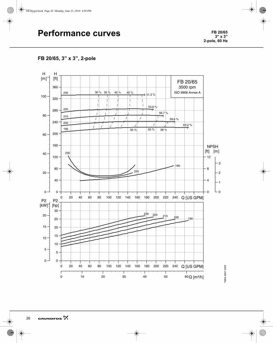
26
FB 20/653” x 3”
2-pole, 60 Hz
FB-Hygia.book Page 26 Monday, June 21, 2010 4:58 PM
FB 20/65, 3” x 3”, 2-pole
TM04
450
7 22
09
0 20 40 60 80 100 120 140 160 180 200 220 240 Q [US GPM]
0
40
80
120
160
200
240
280
320
360
[ft]H
0
20
40
60
80
100
[m]H
0
4
8
12
[ft]NPSH
0
1
2
3
[m]
FB 20/653500 rpm
ISO 9906 Annex A
190
220
230
190
200
210
220
230 30 % 35 % 40 % 45 %
50 %
51.3 %
53.8 %
56.7 %
59.8 %
63.2 %
58 %55 %
0 20 40 60 80 100 120 140 160 180 200 220 240 Q [US GPM]
0
5
10
15
20
25
30
[hp]P2
0 10 20 30 40 50 60Q [m³/h]
0
5
10
15
20
[kW]P2
190200210220230

Performance curves FB 20/653” x 3”
4-pole, 60 Hz
FB-Hygia.book Page 27 Monday, June 21, 2010 4:58 PM
FB 20/65, 3” x 3”, 4-pole
TM04
450
8 22
09
0 50 100 150 200 250 300 350 400 450 500 Q [US GPM]
0
10
20
30
40
50
60
70
80
[ft]H
0
5
10
15
20
25
[m]H
0
10
20
30
[ft]NPSH
0
2
4
6
8
[m]
FB 20/651750 rpm
ISO 9906 Annex A
190
220230
190
200
210
220
230 60 % 66 % 70 %73 %
77 %
60 %
66 %
81.6 %
77.4 %
73.6 %70.1 %
66.9 %
0 50 100 150 200 250 300 350 400 450 500 Q [US GPM]
0
1
2
3
4
5
6
7
8[hp]P2
0 20 40 60 80 100 120 Q [m³/h]
0
1
2
3
4
5
[kW]P2
190200
210220
230
27

Performance curves
28
FB 80/303” x 3”
2-pole, 60 Hz
FB-Hygia.book Page 28 Monday, June 21, 2010 4:58 PM
FB 80/30, 3” x 3”, 2-pole
TM04
451
5 22
09
0 50 100 150 200 250 300 350 400 450 500 550 Q [US GPM]
0
20
40
60
80
100
120
140
160
180
200
220
[ft]H
0
10
20
30
40
50
60
[m]H
0
10
20
[ft]NPSH
0
2
4
6
[m]
FB 80/303500 rpm
ISO 9906 Annex A
150150-6
190
150
150-6
160
170
180
190
73 %
76 %
79 %81 %
81.7 %
81 % 79 %76 %
73 %
60 % 64 % 67 %70 %
76 %
71.6 %
72.7 %
74.5 %
73 %60 %
63 %
65 %
65.8 %
65 %63 %
60 %
0 50 100 150 200 250 300 350 400 450 500 550 Q [US GPM]
0
5
10
15
20
25
[hp]P2
0 20 40 60 80 100 120 Q [m³/h]
0
5
10
15
[kW]P2
150150-6
160
170
180
190

Performance curves FB 80/303” x 3”
4-pole, 60 Hz
FB-Hygia.book Page 29 Monday, June 21, 2010 4:58 PM
FB 80/30, 3” x 3”, 4-pole
TM04
451
6 22
09
0 50 100 150 200 250 300 350 400 450 Q [US GPM]
0
5
10
15
20
25
30
35
40
45
50
55
[ft]H
0
2
4
6
8
10
12
14
16
[m]H
0
5
10
[ft]NPSH
0
1
2
3
[m]
FB 80/301750 rpm
ISO 9906 Annex A
150150-6
190
150
150-6
160
170
180
190
66.3 %
63.8 %
61.3 %
58.9 %
56.5 %55.9 %
50 %
63 %60 %
57 %54 %
50 %
54 %
57 %
60 %
63 %
0 50 100 150 200 250 300 350 400 450 Q [US GPM]
0
1
2
3
4
5
[hp]P2
0 20 40 60 80 100 Q [m³/h]
0
1
2
3
[kW]P2
150
150-6
160170
180
190
29

Performance curves
30
FB 25/604” x 4”
2-pole, 60 Hz
FB-Hygia.book Page 30 Monday, June 21, 2010 4:58 PM
FB 25/60, 4” x 4”, 2-pole
TM04
450
9 22
09
0 20 40 60 80 100 120 140 160 180 200 220 Q [US GPM]
0
40
80
120
160
200
240
280
320
360
[ft]H
0
20
40
60
80
100
[m]H
0
4
8
12
[ft]NPSH
0
1
2
3
[m]
FB 25/603500 rpm
ISO 9906 Annex A
190
220
190
200
210
22030 % 35 % 40 % 43.0 %
45 % 47.3 %
50 % 52.3 %
58.0 %55 %
0 20 40 60 80 100 120 140 160 180 200 220 Q [US GPM]
0
5
10
15
20
25
30
[hp]P2
0 10 20 30 40 50 Q [m³/h]
0
5
10
15
20
[kW]P2
190200210
220

Performance curves FB 25/604” x 4”
4-pole, 60 Hz
FB-Hygia.book Page 31 Monday, June 21, 2010 4:58 PM
FB 25/60, 4” x 4”, 4-pole
TM04
451
0 22
09
0 50 100 150 200 250 300 350 400 450 500 550 Q [US GPM]
0
10
20
30
40
50
60
70
80
[ft]H
0
5
10
15
20
25
[m]H
0
10
20
30
[ft]NPSH
0
2
4
6
8
[m]
FB 25/601750 rpm
ISO 9906 Annex A
190
220
190
200
210
220
70.9 %
69.5 %68.4 %
67.0 %
63 %66 %
69 %
63 %
66 %
69 %
0 50 100 150 200 250 300 350 400 450 500 550 Q [US GPM]
0
2
4
6
8
10
[hp]P2
0 20 40 60 80 100 120 Q [m³/h]
0
2
4
6
[kW]P2
190200210220
31

Performance curves
32
FB 120/304” x 4”
2-pole, 60 Hz
FB-Hygia.book Page 32 Monday, June 21, 2010 4:58 PM
FB 120/30, 4” x 4”, 2-pole
TM04
451
7 22
09
0 50 100 150 200 250 300 350 400 450 500 550 600 Q [US GPM]
0
20
40
60
80
100
120
140
160
180
200
220
[ft]H
0
10
20
30
40
50
60
[m]H
0
10
20
30
[ft]NPSH
0
2
4
6
8
[m]
FB 120/303500 rpm
ISO 9906 Annex A
150
150-6
190
150
150-6
160
170
180
190
61.1 %
60.2 %57 %
53 % 57 % 60 %63 %
67.9 %
64.3 %
62.1 %
60.8 %
60 %
0 50 100 150 200 250 300 350 400 450 500 550 600 Q [US GPM]
0
5
10
15
20
25
[hp]P2
0 20 40 60 80 100 120 140 Q [m³/h]
0
5
10
15
[kW]P2
150
150-6
160170
180190

Performance curves FB 120/304” x 4”
4-pole, 60 Hz
FB-Hygia.book Page 33 Monday, June 21, 2010 4:58 PM
FB 120/30, 4” x 4”, 4-pole
TM04
451
8 22
09
0 50 100 150 200 250 300 350 400 Q [US GPM]
0
5
10
15
20
25
30
35
40
45
50
[ft]H
0
2
4
6
8
10
12
14
[m]H
0
5
10
[ft]NPSH
0
1
2
3
[m]
FB 120/301750 rpm
ISO 9906 Annex A
150
150-6
190
150
150-6
160
170
180
190- 45 %49 %
53 %56 %
59 %62 %
62 %
59 %
56 %53 %
49 %
64.7 %
62.1 %
59.4 %
59.9 %
54.2 %
49.7 %
0 50 100 150 200 250 300 350 400 Q [US GPM]
0
1
2
3
4
5
[hp]P2
0 20 40 60 80 Q [m³/h]
0
1
2
3
[kW]P2
150
150-6
160170
180190
33

34
FB-Hygia.book Page 34 Monday, June 21, 2010 4:58 PM
Dimensions
FB pump on foot-mounted motorModels 10/40, 20/25, 15/40, 25/15
Pump dimensions
Pipe connection dimensionsDimensions depend on housing size (DNs, DNd, a1, h2, e1).
TM04
426
5 10
09
P2 [Hp]
No. of motor poles
NEMAframe size
Motor TEFC C-Face (Baldor Premium Efficient Washdown CEWDM)Dimensions [inch (mm)]
n1 n2 a u k3 m1 m2S m2L s1 h11.0 4 182TCZ
8 5/8(219)
7 1/2(191)
10 1/2 (265)
5 3/4(146)
12 3/8 (316) 6 1/2
(165)4 1/2(114)
5 1/2(140) 13/32
(10.4)
4 1/2(114)
1.5 4 182TCZ2.0 4 182TCZ3.0 2 182TCZ 6 7/8
(175)13 3/4 (350)5.0 2 184TCZ
7.5 2 213TCZ 9 1/2(241)
8 1/2(216)
11 1/4 (287)
8(205)
16 1/2 (420)
8(203)
5 1/2(140)
7(178)
5 1/4(133)
ConnectionsPump model FB 10/40,
FB 20/25FB 15/40,FB 25/15
OD(DNs/DNd)
1½ / 1½ 2 / 2Dimensions [inch (mm)]
Tri-Clamp®
a1 3 1/8 (80) 3 (76)e1 3 3/8 (85) 3 (75)h2 7 1/4 (186) 7 1/4 (186)
FlangeANSI B16.5150 lbs
a1 2 7/8 (73) 3 1/8 (80)e1 3 3/8 (85) 3 (75)h2 6 3/4 (170) 6 3/4 (170)
NPT threadInternal
a1 4 1/8 (106) 4 (102)e1 3 3/8 (85) 3 (75)h2 8 1/2 (217) 8 1/2 (217)
Pump on foot-mounted motor

Dimensions Pump on foot-mounted motor
FB-Hygia.book Page 35 Monday, June 21, 2010 4:58 PM
FB pump on foot-mounted motorModels 30/60, 70/40, 20/65, 80/30, 25/60, 120/30
Pump dimensions
Pipe connection dimensionsDimensions depend on housing size (DNs, DNd, a1, h2, e1).
TM04
426
6 10
09
P2[Hp]
No. of motor poles
NEMAframe size
Motor TEFC C-Face (Baldor Premium Efficient Washdown CEWDM)Dimensions [inch (mm)]
n1 n2 a u k3 m1 m2S m2L s1 h11.0 4 182TCZ
8 5/8 (219)
7 1/2 (191)
11 1/2 (293)
5 3/4 (146)
12 1/4 (312)
6 1/2 (165)
4 1/2 (114)
5 1/2 (140)
13/32 (10.4)
4 1/2 (114)
1.5 4 182TCZ2.0 4 182TCZ
3.0 4 182TCZ6 7/8 (175)
13 3/4 (350)
5.0 4 184TCZ 15 1/4 (356)
7.5 4 213TCZ9 1/2 (241)
8 1/2 (216)
12 3/8 (315)
8(205)
16 1/2 (420) 8
(203)5 1/2 (140)
7(178)
5 1/4 (133)
10 2 215TCZ
15 2 215TCZ 16(457)
20 2 256TCZ 11 1/4 (286)
10(254)
12 7/8 (327)
9.75 (247)
19 1/2 (495)
11 1/4 (286)
8 1/4 (210)
10(254) 17/32
(13.5)
6 1/4 (159)
25 2 284TSCZ 12 3/4 (324)
11(279)
13(330)
12 5/16 (313)
21.5 (546)
12 13/16 (326)
9 1/2 (241)
11(279) 7(178)
ConnectionsPump model FB 30/60,
FB 70/40FB 20/65,FB 80/30
FB 25/60,FB 120/30
OD(DNs/DNd)
2½ / 2½ 3 / 3 4 / 4Dimensions [inch (mm)]
Tri-Clamp®
a1 4 3/8 (112) 4 3/8 (112) 4 3/8 (112)e1 3 7/8 (98) 3 3/8 (86) 3 3/8 (86)h2 8 1/2 (216) 8 1/8 (207) 8 1/8 (206)
FlangeANSI B16.5150 lbs
a1 4 1/2 (116) 4 1/2 (116) 4 1/2 (116)e1 3 7/8 (98) 3 3/8 (86) 3 3/8 (86)h2 7 7/8 (200) 7 7/8 (200) 7 7/8 (200)
NPT thread,internal
a1 5 3/8 (138) 5 3/8 (138) 5 3/8 (138)e1 3 7/8 (98) 3 3/8 (86) 3 3/8 (86)h2 9 3/4 (247) 9 3/8 (238) 9 3/8 (238)
35

Dimensions
36
Pump with feet and support bars
FB-Hygia.book Page 36 Monday, June 21, 2010 4:58 PM
FB pump with feet and support barsModels 10/40, 20/25, 15/40, 25/15
Pump dimensions
1) Adjustable feet: +9/16, –3/8 (+15, –10)
Pipe connection dimensionsDimensions depend on housing size (DNs, DNd, a1, h2, e1).
TM04
426
3 10
09
P2[Hp]
No. ofmotorpoles
NEMA frame size
Motor TEFC C-Face (Baldor Premium Efficient Washdown CEWDM)Dimensions [inch (mm)]
n a u k3 m1 m2 h11.0 4 182TCZ
7 1/2(191)
7 1/2(191)
5 3/4(146)
12 3/8(316) 12
(305)10
(254)8 7/8
(227) 1
1.5 4 182TCZ2.0 4 182TCZ3.0 2 182TCZ 6 7/8
(175)13 3/4(350)5.0 2 182TCZ
7.5 2 213TCZ 8 1/2(216)
7 3/4(198)
8(205)
16 1/2(420)
14(356)
12(305)
9 5/8(246) 1
ConnectionsPump model FB 10/40,
FB 20/25FB 15/40,FB 25/15
OD(DNs/DNd)
1½ / 1½ 2 / 2Dimensions [inch (mm)]
Tri-Clamp®a1 3 1/8 (80) 3 (76)e1 3 3/8 (85) 3 (75)h2 7 1/4 (186) 7 1/4 (186)
FlangeANSI B16.5150 lbs
a1 2 7/8 (73) 3 1/8 (80)e1 3 3/8 (85) 3 (75)h2 6 3/4 (170) 6 3/4 (170)
NPT thread,internal
a1 4 1/8 (106) 4 (102)e1 3 3/8 (85) 3 (75)h2 8 1/2 (217) 8 1/2 (217)

Dimensions Pump with feet and support bars
FB-Hygia.book Page 37 Monday, June 21, 2010 4:58 PM
FB pump with feet and support barsModels 30/60, 70/40, 20/65, 80/30, 25/60, 120/30
Pump dimensions
1) Adjustable feet: +9/16, –3/8 (+15, –10)
Pipe connection dimensionsDimensions depend on housing size (DNs, DNd, a1, h2, e1).
TM04
426
2 10
09
P2[Hp]
No. ofmotorpoles
NEMA frame size
Motor TEFC C-Face (Baldor Premium Efficient Washdown CEWDM)Dimensions [inch (mm)]
n a u k3 m1 m2 h11.0 4 182TCZ
7 1/2(191)
4 1/2(115)
5 3/4(146)
12 1/4(312)
16(406)
14(356)
9 3/8(240) 1
1.5 4 182TCZ2.0 4 182TCZ
3.0 4 182TCZ6 7/8(175)
13 3/4(350)
5.0 4 184TCZ 15 1/4(356)
7.5 4 213TCZ8 1/2(216)
8 7/8(225)
8(205)
16 1/2(420) 14
(356)12
(305)9 3/4
(246) 110 2 215TCZ
15 2 215TCZ 16(457)
20 2 256TCZ 10(254)
9 7/8(251)
9 3/4(247)
19 1/2(495)
17(432)
15(381)
10 7/8(274) 1
25 2 284TSCZ 11(279)
9(229)
12 5/16(313)
21.5(546)
19(483)
17(432)
11 5/8(294) 1
Connections
Pump model
FB 30/60,FB 70/40
FB 20/65,FB 80/30
FB 25/60,FB 120/30
OD(DNs/DNd)
2½ / 2½ 3 / 3 4 / 4Dimensions [inch (mm)]
Tri-Clamp®a1 4 3/8 (112) 4 3/8 (112) 4 3/8 (112)e1 3 7/8 (98) 3 3/8 (86) 3 3/8 (86)h2 8 1/2 (216) 8 1/8 (207) 8 1/8 (206)
FlangeANSI B16.5150 lbs
a1 4 1/2 (116) 4 1/2 (116) 4 1/2 (116)e1 3 7/8 (98) 3 3/8 (86) 3 3/8 (86)h2 7 7/8 (200) 7 7/8 (200) 7 7/8 (200)
NPT thread,internal
a1 5 3/8 (138) 5 3/8 (138) 5 3/8 (138)e1 3 7/8 (98) 3 3/8 (86) 3 3/8 (86)h2 9 3/4 (247) 9 3/8 (238) 9 3/8 (238)
37

38
FB-Hygia.book Page 38 Monday, June 21, 2010 4:58 PM

39
FB-Hygia.book Page 39 Monday, June 21, 2010 4:58 PM

GRUNDFOS Pumps Corporation 17100 West 118th TerraceOlathe, Kansas 66061Phone: +1-913-227-3400 Telefax: +1-913-227-3500
GRUNDFOS Canada Inc. 2941 Brighton Road Oakville, Ontario L6H 6C9 CanadaPhone: +1-905 829 9533 Telefax: +1-905 829 9512
Bombas GRUNDFOS de Mexico S.A. de C.V. Boulevard TLC No. 15Parque Industrial Stiva AeropuertoApodaca, N.L. Mexico 66600Phone: +52-81-8144 4000 Telefax: +52-81-8144 4010
www.grundfos.com
L-FB-PG-001 0710
USRepl. 10/09
© 2009, 2010 Grundfos Pumps Corp.
Being responsible is our foundationThinking ahead makes it possible
Innovation is the essence
The name Grundfos, the Grundfos logo, and the payoff Be–Think–Innovate are registered trademarks owned by Grundfos Management A/S or Grundfos A/S, Denmark. All rights reserved worldwide.
Subject to alterations.
FB-Hygia.book Page 40 Monday, June 21, 2010 4:58 PM