Embed Size (px)
Citation preview

GS 134-7
SPECIAL PURPOSE STEAM TURBINESTO API 612
November 1994
Copyright © The British Petroleum Company p.l.c.

Copyright © The British Petroleum Company p.l.c.All rights reserved. The information contained in this document is subjectto the terms and conditions of the agreement or contract under which thedocument was supplied to the recipient's organisation. None of theinformation contained in this document shall be disclosed outside therecipient's own organisation without the prior written permission ofManager, Standards, BP International Limited, unless the terms of suchagreement or contract expressly allow.

BP GROUP RECOMMENDED PRACTICES AND SPECIFICATIONS FOR ENGINEERING
Issue Date November 1994
Doc. No. GS 134-7 Latest Amendment Date
Document Title
SPECIAL PURPOSE STEAM TURBINESTO API 612
(Replaces BP Engineering Std 198)
APPLICABILITY
Regional Applicability: International
SCOPE AND PURPOSE
This Guidance for Specification covers requirements for Special Purpose Steam Turbines.It is for use with a data sheet to adapt it for specific application.
It supplements the API standard, defining a number of the optional clauses andsubstituting, modifying or qualifying certain other clauses in the light of BP experience.
AMENDMENTSAmd Date Page(s) Description___________________________________________________________________
CUSTODIAN (See Quarterly Status List for Contact)
Rotating MachineryIssued by:-
Engineering Practices Group, BP International Limited, Research & Engineering CentreChertsey Road, Sunbury-on-Thames, Middlesex, TW16 7LN, UNITED KINGDOM
Tel: +44 1932 76 4067 Fax: +44 1932 76 4077 Telex: 296041

GS 134-7SPECIAL PURPOSE STEAM TURBINES
TO API 612
PAGE i
CONTENTS
Section Page
FOREWORD ................................................................................................................. i
1. INTRODUCTION................................................................................................... 1
1.1 Scope ................................................................................................................ 11.2 Alternative Designs.............................................................................................. 11.3 Conflicting Requirements..................................................................................... 1
2. BASIC DESIGN...................................................................................................... 1
2.1 General................................................................................................................ 12.2 Pressure Casing ................................................................................................... 52.3 Casing Appurtenances ......................................................................................... 5
2.3.1 Nozzles and Diaphragms............................................................... 52.3.2 Sentinel Warning Valve................................................................. 6
2.4 Casing Connections ............................................................................................. 62.4.1 See 2.2.10 and 11. ........................................................................ 6
2.5 External Forces and Moments.............................................................................. 62.6 Rotating Elements ............................................................................................... 7
2.6.1 Rotors........................................................................................... 72.6.2 Shafts............................................................................................ 82.6.3 Blading ......................................................................................... 8
2.7 Shaft Seals......................................................................................................... 102.8 Dynamics........................................................................................................... 10
2.8.2 Lateral Analysis ...........................................................................112.8.4 Torsional Analysis........................................................................132.8.5 Vibration and Balancing ...............................................................14
2.9 Bearings and Bearing Housings.......................................................................... 142.9.1 Radial Bearings............................................................................142.9.2 Thrust Bearings and Collars .........................................................142.9.3 Bearing Housings.........................................................................162.9.4 Grounding....................................................................................17
2.10 Lubrication and Control Oil Systems............................................................... 172.11 Materials......................................................................................182.11.1 General ........................................................................................182.11.3 Welding .......................................................................................18
3. ACCESSORIES .................................................................................................... 18
3.1 Couplings and Guards........................................................................................ 183.2 Mounting Plates................................................................................................. 20
3.2.2 Baseplates....................................................................................203.3 Gear Units ......................................................................................................... 213.4 Controls and Instrumentation............................................................................. 21
3.4.1 General ........................................................................................21

GS 134-7SPECIAL PURPOSE STEAM TURBINES
TO API 612
PAGE ii
3.4.2 Control Systems...........................................................................213.4.3 Protective Devices .......................................................................223.4.4 Instrument and Control Panels .....................................................233.4.8 Vibration, Position and Bearing Temperature Detectors ...............24
3.7 Insulation and Jacketing..................................................................................... 243.9 Turning Gear ..................................................................................................... 24
4. INSPECTION, TESTING AND PREPARATION FOR SHIPMENT................ 25
4.1 General.............................................................................................................. 254.2 Inspection.......................................................................................................... 26
4.2.1 General ........................................................................................264.2.2 Material Inspection ......................................................................274.2.3 Mechanical Inspection..................................................................28
4.3 Testing284.3.1 General ........................................................................................284.3.3 Mechanical Running Test .............................................................284.3.4 Optional Tests..............................................................................29
5. VENDOR'S DATA................................................................................................ 30
5.1 Proposals........................................................................................................... 305.2 Contract Data .................................................................................................... 30
5.2.5 Data.............................................................................................30
APPENDIX A.............................................................................................................. 32
CHECK LIST TO API 612 THIRD EDITION - DATA SHEETS........................... 32
APPENDIX F .............................................................................................................. 37
DEFINITIONS AND ABBREVIATIONS .............................................................. 37
APPENDIX G.............................................................................................................. 38
LIST OF REFERENCED DOCUMENTS............................................................... 38
GS 134-7SPECIAL PURPOSE STEAM TURBINES
TO API 612
PAGE iii
FOREWORD
Introduction to BP Group Recommended Practices and Specifications for Engineering
The Introductory Volume contains a series of documents that provide an introduction to theBP Group Recommended Practices and Specifications for Engineering (RPSEs). Inparticular, the 'General Foreword' sets out the philosophy of the RPSEs. Other documents inthe Introductory Volume provide general guidance on using the RPSEs and backgroundinformation to Engineering Standards in BP. There are also recommendations for specificdefinitions and requirements.
Value of this Guidance for Specification
This Guidance for Specification defines a number of the optional API clauses and maysubstitute, add to or qualify other API clauses using BP's knowledge and experienceworldwide.
Application
This Guidance for Specification is intended to guide the purchaser in the use or creation of afit-for-purpose specification for enquiry or purchasing activity.
It is a transparent supplement to API 612 Third Edition, dated November 1987, showingsubstitutions, qualifications and additions to the API text as necessary. As the titles andnumbering of the BP text follow those of API, gaps in the numbering of the BP documentmay occur. Where clauses are added, the API text numbering has been extended accordingly.
Text in italics is Commentary. Commentary provides background information which supportsthe requirements of the Specification, and may discuss alternative options.
This document may refer to certain local, national or international regulations but theresponsibility to ensure compliance with legislation and any other statutory requirements lieswith the user. The user should adapt or supplement this document to ensure compliance forthe specific application.
Specification Ready for Application
A Specification (BP Spec 134-7) is available which may be suitable for enquiry or purchasingwithout modification. It is derived from this BP Group Guidance for Specification byretaining the technical body unaltered but omitting all commentary, omitting the data page andinserting a modified Foreword.

GS 134-7SPECIAL PURPOSE STEAM TURBINES
TO API 612
PAGE iv
Feedback and Further Information
Users are invited to feed back any comments and to detail experiences in the application of BPRPSE's, to assist in the process of their continuous improvement.
For feedback and further information, please contact Standards Group, BP International orthe Custodian. See Quarterly Status List for contacts.

GS 134-7SPECIAL PURPOSE STEAM TURBINES
TO API 612
PAGE 1
1. INTRODUCTION
1.1 Scope
This document specifies BP requirements for special purpose steamturbines conforming generally to API 612. They shall meet therequirements of API 612, third edition, November 1987, (adopted asANSI/API Std 612-1992) as amplified and modified herein.
(Qualification)
1.2 Alternative Designs
Designs alternative to those prescribed will be acceptable provided itcan be shown to the satisfaction of the purchaser's professionalengineer that the required performance and function are attained.
Referenced standards may be replaced by equivalent standards that areinternationally or otherwise recognised provided that it can be shown tothe satisfaction of the purchaser's professional engineer that they meetor exceed the requirements of the referenced standards.
(Substitution)
1.3 Conflicting Requirements
In case of conflict between various documents their order ofprecedence shall be:-
(a) Local Authority or Statutory Regulations
(b) The Equipment Requisition or Order
(c) Data Sheets
(d) This specification
(e) Referenced industry standards
(Substitution)
2. BASIC DESIGN
2.1 General
2.1.1 Turbines shall be sufficiently robust to withstand without damage theresults of occasional abnormal conditions of limited duration, such assurging of compressors, or electrical faults on generators.

GS 134-7SPECIAL PURPOSE STEAM TURBINES
TO API 612
PAGE 2
(Addition)
Normally turbines to API 612 are for use on continuous running duties. The numberof starts experienced during the machine lifetime is therefore relatively small.Starting procedures designed to minimise casing transient thermal stresses arespecified by the vendor, therefore casing life is not critical.
However, it is essential to validate these assumptions on specific applications.
2.1.3(b) API 612 acknowledges that careful consideration needs to be given to thespecification of the minimum inlet steam conditions and coincident maximumexhaust conditions, to prevent oversizing of the turbine.
Oversizing can lead to reduced efficiency at the normal operating points, highgoverning stage stresses at the first control valve point, and possible overloading ofblading.
For the governing stage, tangential steam loading and blade heights increase whena reduced nozzle arc is used for normal operation, i.e., when the size of the inletarc has been increased to accommodate off-design steam conditions.
An increase in tangential load or blade height increases the bending stress.
The tangential load increases on two counts:-
(i) The number of moving blades exposed to the nozzle arc reduces withreducing arc and hence the load per blade increases.
(ii) The energy drop across the stage increases as the percentage arc reduces.This happens because the wheel bowl pressure reduces with reducing flowto the wheel bowl.
The blade height increases to compensate for the reduced nozzle arc.
Increased nozzle area permits increased flow to the turbine. Flow willincrease in response to increased load or the same load at reducedconditions. Both situations should be reviewed to ensure the bladingdesign is adequate, or any operating limits identified, and appropriatesafeguards provided.
Machine costs and complexity can increase if 360 degree arc inlets or by-pass control become necessary to meet these conditions.
A 40% increase in nozzle area over rated duty at normal conditions cangenerally be accommodated without compromising efficiency, strength, orcosts.
Some vendors (European principally) offer by-pass governing toaccommodate these requirements.
2.1.3(d) The performance of condensers new and clean will be better than the design whichwill be based on the fouled condition. When a condenser with a divided water boxis to be available for on-line cleaning or operated with only half the condenser in

GS 134-7SPECIAL PURPOSE STEAM TURBINES
TO API 612
PAGE 3
service, the turbine duty may have to take this operating condition into account.On-line cleaning methods have gone some way towards reducing the variations incondenser performance over the required period of uninterrupted operation.
Condensing turbines exhausting to condensers which have divided water boxes forin-service cleaning may generate lower pressures when the full surface is inservice.
Also, condenser pressure may reduce with falling cooling water temperature.
Lower pressures may lead to overstressing, and increased water erosion of exhaustblading unless the vacuum is controlled by judicious condenser sizing or bybleeding air, or by adjusting the operation of the condenser vacuum equipment.
2.1.3(e) Operation of a compressor at high suction pressure can lead to increased powerconsumption and torques. The oversizing implicit in 2.1.3(b) may then lead tooverstressing of blading.
2.1.3(f) The sizing of the control nozzles for the condensing sections of extraction orinduction turbines requires attention to avoid the possibility of overloading theexhaust blading. The sizing of these nozzles should be reviewed with the vendor.
The maximum operating value of the extraction or induction pressure should beestablished. This, together with the nozzle areas, will determine the maximumpossible flow and hence loading on the blading. This needs to be considered incondensing section blade stressing, and any operating limits identified andappropriate safeguards provided.
2.1.11 Noise limits will normally be specified in detail in an enquiry.However, in the absence of such requirements, noise levels at orbeyond 1 m (3 ft) from the machine (driver plus driven machine,transmission and auxiliaries) surfaces should not exceed 85 dB(A).
The 85 dB(A) limit is based upon an 8 hour exposure. Where operating shiftsexceed 8 hours and maintenance activity may be required in the area of anoperating turbine the limit may require to be reduced to 83 dB(A).
The sound intensity method for measuring the noise level of equipment offerssignificant advantages over conventional sound pressure measurement techniques.These are:-
(a) Measurement of sound radiated from each surface or area of theequipment. This enables the principal contributors to overall noise level tobe identified and reduced by locally applied absorption materials.
(b) Improved compensation for background and reverberative effects.
When a vendor cannot meet the limits without the addition of noiseattenuation features, the levels with and without these features shall bestated in his proposal. Noise attenuation measures proposed by thevendor shall not conflict with the other requirements of this Standard.
A vendor shall provide details of the noise emission in octave bandsfrom his equipment, obtained by the methods of test specified in
GS 134-7SPECIAL PURPOSE STEAM TURBINES
TO API 612
PAGE 4
EEMUA Publication 140 or a method of test approved by BP. Avendor shall also provide details of any narrow-band noise emitted byhis equipment which is noticeable to the ear, and the octave band orbands in which it occurs.
Noise attenuating enclosures will only be accepted when there is noalternative form of noise control. The design of these enclosures shallbe such that normal operation and maintenance are not undulycompromised. All instrumentation and controls shall be either mountedexternally to the enclosure or shall be clearly visible and controllablefrom outside the enclosure.
Enclosures shall be adequately purged and cooled. Instrumentation,sensors and cables installed inside enclosures shall not be subjected toan environment which causes the component to be operated outside thevendor's specified ambient temperature limits.
Where the area classification would otherwise be Zone 2, equipmentwithin an enclosure will normally need to be suitable for a Zone 1 area.
(Substitution)
2.1.15 For electric power generation applications, the turbine vendor shall beresponsible for the co-ordination of the design and for the satisfactoryfunctioning of the complete unit, i.e. turbine, generator, transmissionand ancillaries. In cases where the turbine vendor supplies equipmentthat they have not manufactured, they shall be responsible for ensuringthat the designs of these items are compatible with each other and withtheir own equipment in all respects.
The satisfactory functioning of the complete unit shall form part of theturbine vendor's contractual guarantee.
For other applications, the driven equipment vendor will normally beresponsible for overall co-ordination. The turbine vendor shall co-operate with the driven equipment vendor to facilitate the developmentof the complete unit.
(Substitution)
The responsibilities defined in this Specification are generally valid. However, theallocation of overall responsibility for the train may vary on a case to case basisdepending upon the application, technical complexity and relative value of thedriving and driven equipment.
The turbine vendors responsibility should in any case include the condenser and itsauxiliaries.
2.2 Pressure Casing
2.2.3 For turbines with dedicated condensers, a relief valve mounted on the condensershell is required, as part of the condenser vendor supply. (Sized to H.E.I.requirements).

GS 134-7SPECIAL PURPOSE STEAM TURBINES
TO API 612
PAGE 5
For other applications ensure that relief valves are included in the lines upstreamof block valves.
2.2.9 Each drain shall be individually valved and piped to the edge of theturbine base. Valves shall be accessible from the operating floor.
(Addition)
2.2.10 & 11 Studded connections on casing nozzles hinder installation and maintenance sincepiping has to be sprung in order to remove casings or pipe spools.
Above circa 413°C bolting is subject to creep stress relaxation and may requireperiodic replacement.
During dismantling if a nut or tapped thread binds, replacement of studs becomesproblematic compared to through bolting, which can be sawn or burnt off.
2.2.12 Bolt tensioning systems using electric heaters should preferably beavoided on machines to be installed in hazardous areas.
(Addition)
Bolting, particularly at the main casing horizontal joint may be large; spannertightening becomes impractical and hydraulic stretching or electric heatingbecomes essential.
Hydraulic tensioning is preferred to electric heating in hazardous areas. However,vendor standard designs may not have access for hydraulic systems, and electricheating may have to be accepted subject to working with a hot work permit.
2.3 Casing Appurtenances
2.3.1 Nozzles and Diaphragms
2.3.1.1 The need to replace nozzles arises from:-
(a) Abrasive wear on high pressure drop governing stages (particularly partload nozzle banks).
(b) Need to re-rate turbines.
Abrasive wear may be caused by passage of debris (pipe scale, weld spatter andslag, shot etc.) or wet steam. The effects can be minimised by careful pre-commissioning and pipe descaling. The use of in-line vortex separators can removedebris and free water.
Non-welded nozzles can be replaced in the field. Nozzles welded to a casing willrequire removal by machining.

GS 134-7SPECIAL PURPOSE STEAM TURBINES
TO API 612
PAGE 6
Non-welded nozzles may experience steam cutting where they are located in casinggrooves, especially on high pressure drop or wet applications. Vendor experienceneeds to be reviewed where a deviation is requested.
Where nozzles are mounted in nozzle belts which can be removed piece-small to alocal workshop, then the welded type may be acceptable. In general thisarrangement is used on high pressure (Class 900 plus) applications, where pressuredrop and hence need for welding is greatest.
2.3.1.2 Impulse turbines employ diaphragm nozzle blade carriers set into individualgrooves in the main casing.
Generally, reaction turbines employ a stationary blade carrier in the form of aninner casing. The blades are set into grooves in this casing. However, somereaction designs do employ a diaphragm style nozzle carrier, which is still housedin a carrier.
2.3.2 Sentinel Warning Valve
Sentinel warning valves shall be supplied.
(Qualification)
Sentinel warning valves may be considered of use only where operators areconsistently within audible distance. If this is not the case they may not bespecified.
For non condensing steam turbines the exhaust temperature may be higher than thetemperature limit for some brasses and bronzes. The valve material must besuitable for the maximum steam temperature.
2.4 Casing Connections
2.4.1 See 2.2.10 and 11.
2.4.6.4 The vendor shall furnish mating parts of connections larger than thosecovered by ANSI.
(Qualification)
2.5 External Forces and Moments
The pipe force and moment limits permitted by API 612 are lower than for othertypes of machinery (pumps and compressors).
Steam turbines have bearing housings which support the steam casing, whereaswith pumps and compressors the casing supports the bearing housing.
As a consequence, the steam turbine rotor to stator alignment is more sensitive topipe loadings. Steam pipe and casing thermal growth may be an order ofmagnitude greater than on pumps and compressors. Steam pipe designs need to beflexible and the positions of anchors, guides and spring hangers carefullyconsidered.

GS 134-7SPECIAL PURPOSE STEAM TURBINES
TO API 612
PAGE 7
The use of twin connections can aid by balancing pipe loads, and may be justifiedon larger machines.
Passout, backpressure or induction lines may be more difficult to design because oftheir greater size and stiffness. Here again, twinning of pipes may be justified.
The design of piping systems should be carefully reviewed with the contractor andvendor.
If after an exhaustive investigation of pipe runs, dual connections, anchor supports,cold draw etc. it proves impossible to achieve mutually acceptable pipe loadings,then on low pressure systems (ANSI 30 0 lbs.) the use of flexible bellows may beconsidered. It is anticipated that this concession will only need to be applied to lowpressure systems.
2.6 Rotating Elements
2.6.1 Rotors
2.6.1.3 Built-up rotors are most common in American designed turbines. European designsonly use built-up rotors where size precludes the use of solid forged rotors(800/1000 MW).
Potential difficulties with built up rotors are:-
(a) Stress raisers due to keys, and/or shrink fits. The latter can be very severe.
(b) Discs loosening due to centrifugal and/or t hermal gradients, particularlyduring run-up.
(c) Introduction of cross-coupling from shrink fits contributing to sub-synchronous whirl.
(d) Fretting at the shrink interface.
(e) Thermal bending of rotors caused by differential heat transfer at shrinkinterfaces.
It is essential to ensure adequate interference fits to eliminate loosenessand fretting, but not so severe as to induce rotor instability, or high stressconcentrations.
The number and rate of start-up influences thermal gradient loosening.
This type of rotor should only be accepted where there are strongeconomic incentives and existing designs, (identical steam conditions,power, speeds) with 5 or more years satisfactory operating experience.
2.6.1.5 For machines operating above the first flexible mode, balancing planesshall be provided between bearings to allow field balancing afterinstallation. Provision shall be made for ready external access (notrequiring removal of the case) at the balancing planes.

GS 134-7SPECIAL PURPOSE STEAM TURBINES
TO API 612
PAGE 8
(Substitution)
In-place balancing offers significant advantages in reducing plant downtime, andprovision should always be specified.
A minimum of two planes is required. Ideally these should be outside the casings;however, rotor dynamics may dictate that they are within the casings.
The need for, and location of other planes within the casing depends upon the rotormode shape(s) in the operating speed range. These should be studied by forcedresponse calculations.
In general, the first and second flexural modes can be two plane balanced, highermodes may require additional planes.
2.6.2 Shafts
2.6.2.7 The turbine vendor shall, jointly with the driven equipment vendor,establish the maximum transient torques that will occur in the shaftingsystem under startup, running, and fault conditions. All components,including the coupling, and the fit of the coupling hub on the shaft, shallbe suitable for at least 115% of this figure. See 2.8.4.1 and 2.8.4.2.
(Addition)
2.6.3 Blading
2.6.3.1 For each blade row, the vendor shall verify by Campbell diagrams ortheir equivalent (corrected to actual operating temperatures andspeeds) that excitation of in-phase tangential, out-of-phase tangential,axial, torsional, and any other high-response modes by multiples of upto 15 times running speed, by nozzle passing frequency, and by twicenozzle passing frequency does not occur within the range 90%minimum speed to 110% maximum continuous speed.
(Modification)
The origin of blade natural frequency data should be reviewed. Frequently this iscalculated from test results, and as such subject to considerable scatter. Thisscatter leads to the probability of resonance, particularly at high engine orders.
At low engine orders (2-5) it may be possible in theory to avoid resonances.However, this will probably require static frequency checking of individual bladesto control scatter to acceptable levels.
In general therefore it is safest to assume that resonance will occur at the closestlower engine order in the case of long blades and between the nozzle passingfrequency or twice nozzle passing frequency and the closest natural vibration modein the case of short blades. The vendor should demonstrate that in thesecircumstances the vibration stresses are safe.

GS 134-7SPECIAL PURPOSE STEAM TURBINES
TO API 612
PAGE 9
Vendors will employ their own evaluation techniques, data for which may beproprietary.
The methodology employed by the vendor should be reviewed to ensure that as aminimum it takes account of the following:-
(a) Steady steam bending stresses at the most severe operating condition.
(b) The vibration mode and form of shrouding or lacing employed e.g. freestanding, integral shroud free standing, integral shroud firm contact,riveted shroud (No. of shroud or lacing packets and blades per packet).
(c) The effects of irregularities in the steam flow created by blade wakes andother non-uniformities such as:-
(i) Variations in blade to blade pitch
(ii) Variations in axial location of blade trailing edges
(iii) Variations in pressure caused by control valve or nozzlegroupings, extraction flows, ribs up or downstream in the flowpath and non-uniform velocities in exhaust casings
(iv) Variation in energy resulting from the use of nozzle groupingsand by-pass overload control
(d) Damping at the resonant condition.
(e) Stress concentrations, particularly at the junction of aerofoil and rootplatform.
(f) Operation in the transition zone.
The transition point is not fixed on the turbine expansion line. It will varywith steam inlet temperature and the flow rate to the LP section,particularly for extraction turbines. This creates a 'zone' in which thetransition point can occur.
The possibility of the presence of damaging chlorides at the transitionpoint makes it essential that all stages which may fall into the transitionzone are designed to be safe in a chloride atmosphere.
The turbine expansion line should be drawn for the range of powers andinlet steam conditions specified.
2.6.3.3 Blading that could be in the transition zone between the dry and wetregions under any operating conditions shall be conservatively designedwith low working stresses. It shall be assumed that chlorides could bepresent, and the fatigue strength of blading materials shall be selectedaccordingly. See 2.11.1.6.
(Addition)
See commentary 2.6.3.1(f).
GS 134-7SPECIAL PURPOSE STEAM TURBINES
TO API 612
PAGE 10
2.6.3.4 All blading shall have been proven in service, and the vendor shalldemonstrate satisfactory operating experience with each blade profileand height.
The vendor shall state whether the response frequencies have beensubstantiated by static or rotating tests.
(Addition)
2.6.3.5 The vendor shall advise any operating constraints imposed by bladinge.g. limits on extraction, induction and exhaust pressures, temperaturesand flowrates.
(Addition)
2.7 Shaft Seals
2.7.1 Outer labyrinths of the spring loaded carbon packing type have the advantage ofclose clearance running and hence are able to reduce steam leakage toatmosphere. This reduces the risk of steam/condensate escaping to atmosphere andpossible ingress into bearing housings (see 2.7.5 of API 612). However, they aresubject to wear which may eliminate this advantage.
Carbon ring packings are generally limited to rubbing speeds up to 44 m/sec.
2.8 Dynamics
API 612 paragraphs 2.8.1, 2.8.2 and 2.8.3 and Appendix C comprehensively coverthe requirements for analysis of rotor lateral critical speeds.
The procedure improves on earlier API requirements by relating separationmargins to amplification factors, acceptable amplitudes to internal clearance andtest bay verification of calculation assumptions.
However, the testing will be time consuming, and final verification is left until theend of the design manufacturing cycle when the scope for remedial action islimited.
It is essential to review the source and quality of vendor data and correlationsbetween calculation and test from previous jobs.
In general, flexural modes with nodes close to the bearings are lightly damped withthe critical speed heavily dependent on accurate stiffness predictions. Flexuralmodes with nodes remote from the bearings are likely to be more heavily dampedwith a satisfactory result dependent on accurate damping predictions.
Bouncing or conical modes entail significant movement at the bearings and aretherefore normally heavily damped and dependent on accurate dampingpredictions.
Reaction turbine rotors, because of their drum design, tend to be stiffer thanimpulse turbine rotors. As a result their flexural critical speeds are higher thanthose of impulse turbines.

GS 134-7SPECIAL PURPOSE STEAM TURBINES
TO API 612
PAGE 11
For power generation duties the first flexural critical speed of reaction turbineswill be above running speed, with the heavily damped bouncing and conical modesbelow running speed. Although some instances exist in old designs where thesemodes are at running speed; no problems have been reported. The stiffer design isalso less sensitive to thermal bending with consequent easier run-upcharacteristics.
The more flexible impulse turbine rotor runs above its first critical speed and belowor at its second critical speed, although some impulse turbines in the 1-4 MW rangehave 'stiff' rotors.
For many mechanical drive applications these comments are also valid. For higherpower and higher speed condensing and passout condensing applications, reactionturbine rotors are designed to run between their first and second flexural criticalspeeds. The equivalent impulse design may operate above its second critical speedand possibly close to its third.
The greater stiffness of the reaction turbine shaft gives it greater resistance to crosscoupling. Hence, bearings with poorer cross coupling and better dampingcharacteristics can be employed. (See 2.8.2.8 below).
In summary, it can be stated that reaction turbines because of their stiffer rotorspresent an easier rotor dynamics design problem than impulse turbines.
2.8.2 Lateral Analysis
2.8.2.3 A train lateral analysis is required when the shafts of elements of the equipmenttrain are solidly coupled.
The effects of misalignment on bearing loads, stiffness and critical speeds must beevaluated.
The effects of foundation settlement, solar heating, pipe loading, alignment errorsetc. need to be reviewed and evaluated.
2.8.2.4b The units of the SI version of equation (1) are incorrectly stated. They should bemicrometers not millimetres.
2.8.2.4e The vendor shall supply a stiffness map as specified in API 612.
(Qualification)
2.8.2.8 The vendor shall perform a stability analysis to demonstrate that self-excited vibration will not occur under any loading condition.Assumptions regarding the magnitude of excitations from oil film,aerodynamic and other sources shall be stated.
(Addition)
Self-excited vibrations result from cross coupling forces applied to the rotor. Theseoriginate in:-

GS 134-7SPECIAL PURPOSE STEAM TURBINES
TO API 612
PAGE 12
(a) The journal bearings
(b) Shaft labyrinths
(c) Blade tips
(d) Shrink fits
(b) and (c) are density dependent, the effects therefore increase with steampressure.
They are also a function of the tangential velocity of the steam in the closeclearances of labyrinths and shrouded blade tips. The effects can be significantlyreduced by destroying the tangential components of velocity at entry to theclearance space. This is done with radial vanes fitted at the entrance.
The measure of sensitivity to instability is the logarithmic decrement of vibrationamplitude. This increases with rotor stiffness, as does the stability.
The journal bearing geometry has a major influence on the logarithmic decrement,due to its influence on cross coupling force magnitude. However, the bearingswhich suppress cross coupling best have the lowest damping against lateralvibrations, and therefore increase the rotor sensitivity to out of balance.
The following table shows these effects qualitatively on a scale in which 1 is thebest:-
Type of Journal Cross Coupling Damping RankingSuppression Ranking
Cylindrical 5 1Lemon bore (2 lobe) 4 23-lobe 3 34-lobe 2 4Tilting pad 1 5
Not listed is the off-set halves type of bearing which has cross coupling suppressionsecond only to the tilting pad, with damping second only to the cylindrical.Unfortunately it is uni-directional and not suited to mechanical drive applications,if reverse rotation is a possibility.
Tilting pad journal bearings are required on impulse turbines where the flexiblerotors lead to poor damping and low logarithmic decrements. For reaction turbineswith stiffer shafts, lemon bore, 3 or 4 lobe bearings are adequate because reactionturbines have lower sensitivity to out of balance as noted in 2.8.
As noted in 2.6.1.3 shrunk-on discs contribute to cross coupling and experiencewith this type of machine needs to be carefully reviewed.
Second order effects on stability limits are:-
(1) Bearing clearance, reduce to increase stability

GS 134-7SPECIAL PURPOSE STEAM TURBINES
TO API 612
PAGE 13
(2) Oil viscosity, increase to increase stability
(3) Pre-load, increase to increase stability
(4) Bearing specific load, increase to increase stability
These factors need to be reviewed in the detail analysis of rotor stability, for theselected bearing type since they are dependent on manufacturing tolerances,operating conditions, and alignments.
2.8.4 Torsional Analysis
2.8.4.1 Potential sources of torsional excitation to be considered shall includesurge of compressors and electrical faults and mal-synchronisation onelectric generators.
(Addition)
2.8.4.2 For generator drive applications the lowest torsional resonance of thecomplete train shall be at least 30% below the frequency of theelectrical system.
(Addition)
Surge is a potential source of excitation of torsional vibrations. It will certainlyexcite free vibration, which will probably not be damaging. However, no analysisis known which predicts the magnitude and frequency of a surge, hence its effectcannot be quantified. The vendor and contractors experience should be reviewed.
Electrical fault excitation can occur from short circuits or mal-synchronisation ofgenerators.
The most severe short circuit condition is phase to phase; this will produce air gaptorques at system frequency.
180 degree mal-synchronisation is potentially more severe. Protection againstmal-synchronisation should be provided. If on review this can be shown to bereliable, then this case may be ignored.
The 30% margin specified in 2.8.4.2 should provide an adequate safety marginagainst short circuit or mal-synchronisation. If this margin is not practicable thena forced damped response analysis should be performed in order to verify thattorques will be acceptable.
2.8.4.5 The turbine vendor shall perform a torsional vibration analysis of thecomplete coupled train if they have responsibility for overall co-ordination. See 2.1.15.
(Substitution)
2.8.5 Vibration and Balancing
2.8.5.2 Balancing procedures shall be such that rotor and couplinginterchangeability can be achieved without the need for rebalancing.

GS 134-7SPECIAL PURPOSE STEAM TURBINES
TO API 612
PAGE 14
This will require rotors to be first balanced without couplings, and thento be check balanced with coupling hubs mounted.
(Addition)
2.8.5.4 High speed balancing is an acceptable method for balancing rotors. It should bepreceded by a low speed balance.
The technique gives a greater certainty of meeting final test acceptance limitsbecause it shakes out blade path settlement.
Rotors subjected to only a low speed balance may require balancing adjustmentfollowing initial test bed trials.
2.9 Bearings and Bearing Housings
2.9.1 Radial Bearings
For mechanical drive applications, radial bearings shall be capable ofwithstanding reverse rotation for short periods of time without damage.
Radial bearings shall be fabricated so that it is not possible to installthem in any but the correct way.
(Addition)
2.9.2 Thrust Bearings and Collars
2.9.2.1 For mechanical drive applications, thrust bearings shall be capable ofwithstanding reverse rotation for short periods of time without damage.
Thrust bearings shall be fabricated so that it is not possible to installthem in any but the correct way.
(Addition)
2.9.2.6 The vendor shall submit a graphic display of speed against maximumload capacity showing the boundaries defined by the criteria below:-
(i) The minimum oil thickness for continuous operation.
(ii) The maximum bearing lining temperature for continuousoperation.
(iii) The fatigue or mechanical limit for the bearing or its liningmaterial.
This graph shall also indicate the maximum continuous and transientloads applied to the bearings.
(Addition)

GS 134-7SPECIAL PURPOSE STEAM TURBINES
TO API 612
PAGE 15
The oil film thickness can be determined by calculation. It is a function of padgeometry (shape), dimensions, speed, viscosity, bearing oil supply (i.e. directed orflooded lubrication), pivot location (central or offset) and load.
The minimum acceptable oil film thickness for continuous running is empiricallydetermined and usually conservative.
Typical limits as a function of pad radial length published by Michell Bearing Co.are tabulated below for centre and offset pivots
Radial length mm 25 50 75 100 125Centre pivot microns 10 13 15 17 19Offset pivot microns 8 11 13 14 15
The load applied should be 50% of that to produce the above film thickness.
Film thickness is increased by increasing viscosity either by higher index oil orlower oil film temperature. Lower oil film temperatures result from using directedlubrication, higher conductivity pad materials, or reduced oil supply temperatures.
The bearing lining metal temperature is a function of the same parameters as oilfilm thickness. In addition offset pivots reduce oil temperature. The maximum padtemperature is taken to occur at the 75/75 position i.e. 75% of pad width back fromthe leading edge and 75% of pad radial length up from the pad internal diameter.
The ability of offset pivots to run backwards must be reviewed. Some vendors claimadequate capability for offset pivots.
Temperature failure can occur from two modes:-
(a) Melting. This can result from severe overload or loss of oil, and failure isinstantaneous.
(b) Surface metal deterioration. This results in cracking and spalling of thelining material, and failure occurs over a period of hundreds of hours.
The temperature limit depends upon the lining metal. However for the white metalscommonly used in industry, an upper limit of 140°C is generally accepted. Thisleads to a continuous operating limit of circa 120°C, which is the temperatureresulting from applying a load 50% of that to produce 140°C.
However, temperatures of this magnitude can produce problems of oil lacquering ofpad surfaces due to water contamination evaporating from the surface. For steamturbine applications the highest metal temperature in operation should be below100°C (say 95°C) and the design should take account of any uncertainties whichmight lead to the design temperature being exceeded.
Lacquering of surfaces above 100°C has occurred with lubricating oils, with highlevels of EP additives and additive constituents with a phosphorous base. Oils ofthe BP Energol THB type with a zinc based additive constituent rather thanphosphor based have proved satisfactory up to 120°C.
Pad temperatures can be reduced as outlined earlier for oil film temperaturereduction, in addition, load reduction may be possible. However, in certain limitdesigns, it may not be possible to reach these temperatures; the vendor and specific

GS 134-7SPECIAL PURPOSE STEAM TURBINES
TO API 612
PAGE 16
site experience, together with water ingress prevention and removal measuresshould be reviewed before accepting higher temperatures.
The fatigue or mechanical limit is defined by the static load capability of the pad orpivot - deflection and indentation, or the fretting of pivots. This load generallyoccurs at 35 to 40 bar specific pad load.
2.9.2.8 When integral collars are provided, the design shall permit replacementwith a shrunk on collar in the event of severe damage.
The ability to replace integral collars in the event of a catastrophic failure isdesirable. However, with certain designs, e.g. where for rotordynamic reasons thethrust collar is in-board of the journal bearing, this may not be practical.
2.9.3 Bearing Housings
2.9.3.1 Bearing housings shall be fitted with connections for breathers or vents.
(Addition)
2.9.3.2 Air or nitrogen buffering shall be designed to purge the oil labyrinths with an axialvelocity of 4.5 to 6.0 metres per second. Allowance should be made for wear to 2xdesign clearance.
These measures combined with gland condensers and possibly carbon labyrinths(2.7.1) combine to minimise ingress of steam vapour into bearing housings. Inaddition, careful design of any vertical drain legs is required. (See 2.9.3.8).
2.9.3.5 Accelerometers are not normally necessary if shaft proximity probes are fitted.
2.9.3.7 Thrust bearings and radial bearings shall be fitted with bearing metaltemperature sensors in accordance with clause 3.4.4 of API 670.
(Substitution)
Bearing metal temperature sensors give the most accurate indication of the bearingtemperature. However, the sensors are not totally reliable and installed spares arerecommended. These can be independent or dual sensors. They should be hooked-up to the instrument junction box or otherwise suitably terminated.
The sensor installation proposed by the vendor should be reviewed as follows:-
(i) Check that thrust sensors are in a 75/75 position (see 2.9.2.6).
(ii) Check that journal sensors are close to the point of maximum temperature.The position of this point will vary with bearing design.
(iii) Check the method of securing the sensors in place. This should ensure thatthe sensor is in intimate contact with the white metal, and secure. Springloading or epoxy embedding have proved successful. Embedding in thewhite metal is not essential. Avoid loose fitting sensors since these canlose contact with the white metal and give false readings.
GS 134-7SPECIAL PURPOSE STEAM TURBINES
TO API 612
PAGE 17
Sensors enable the machine design basis to be verified and are particularly usefulon thrust bearings, where increasing temperatures (at a given speed) indicateincreasing load from fouling, balance drum wear, or bearing lacquering. Otherfaults such as inadequate lubrication or ingress of abrasives will also increasetemperature.
On journal bearings monitoring temperature can aid in diagnosing misalignment,lubrication problems, lacquering or ingress of abrasives.
2.9.3.8 Vertical legs in a lube oil drain line causes the falling oil to entrain air. Thiscauses two problems:-
(a) Excessive oil vapour in the lube reservoir.
(b) Moist air to be drawn into the bearing housing either via the housingbreather or the shaft oil seal.
Correct sizing of the drain eliminates this effect i.e. drain flow velocity not greaterthan 0.97D 1/2m/sec where D = pipe diameter in metres (1.76D 1/2 ft/sec where D =pipe diameter in ft). These criteria are based on a maximum Froude Number of0.31 for a pipe to be self venting in vertical downflow.
A site fix for this problem is to install an air recycle line from the bottom to the topof the vertical drain pipe.
Notwithstanding the measures outlined here and in 2.9.3.2 to eliminate moisture, itis still recommended that the oil system be provided with facilities for removal ofmoisture. (2.10.4).
2.9.4 Grounding
Brushes suitable for use in oil mist environments are available. Consideration mustbe given to in-service replacement of worn brushes or ensure adequate brush lengthis provided to last between planned overhauls.
Brushes are essential on condensing turbines because of the potential build-up ofstatic electricity caused by wet steam flowing through the exhaust blading.
2.10 Lubrication and Control Oil Systems
2.10.4 Pressurised oil systems shall conform to the requirements of BP GroupGS 134-3.
(Substitution)
The type of water removal device specified shall be mutually agreed with thevendor, to maintain moisture levels within his specified limits.
The effect of moisture removal o n lube oil additive depletion must also beconsidered, together with facilities and procedures for on-line additivereplenishment.
In addition, for vacuum systems, additive depletion may be inherent in the vacuumprocess.

GS 134-7SPECIAL PURPOSE STEAM TURBINES
TO API 612
PAGE 18
2.11 Materials
2.11.1 General
2.11.1.6 For the purpos es of evaluating the vibration stresses in blading, it shall be assumedthat steam contains < 1% NaC1 in the transition zone. However, since chlorideconcentrations can build up at the wet dry interference in the transition zone theconcentration of NaC1 in the steam is only one consideration; the selection ofblading materials and their allowable stress values should take account of thelikelihood of chlorides.
The presence of corrosive agents in the environment can influence the choice ofmaterials for components exposed to the atmosphere e.g. high salinity environmentsaffect choice/use of austenitic stainless steels, sulphur dioxide, and ammonia affectthe use of non-ferrous alloys. These agents will be project dependent.
2.11.3 Welding
2.11.3.6.1 The NDT requirement for piping should be based on a criticality concept.
This would define a criticality rating (usually 1, 2, 3 or 4) based on size, pressureand temperature rating, materials and service conditions.
The specification should be consistent with the requirements for piping elsewhereon the plant, forming part of the same project.
The NDT requirements for casings (wall and weld) shall be based on the vendorsnormal practice reviewed against the recommendations of API 612 4.2.2 and anydefined criticality ratings.
2.11.3.6.4 Connection designs for class 900 and above should be submitted for approval.
3. ACCESSORIES
3.1 Couplings and Guards
The material of guards shall be sheet steel unless conditions specificallyrequire an alternative. Coupling guards shall be sufficiently robust toresist distortion under typical industrial maltreatment with consequentrisk of sparking by contact with moving parts.
(Addition)
3.1.2 Coupling hubs shall be designed for hydraulic mounting anddismounting.
All moving parts shall be guarded in accordance with national standardsand national statutory regulations.
Gear couplings shall not be used without specific approval of thepurchaser.

GS 134-7SPECIAL PURPOSE STEAM TURBINES
TO API 612
PAGE 19
If used their design shall permit inspection of the teeth withoutdisturbing the hubs.
When these couplings are used they shall be of anti-sludging design andbe lubricated via 2, dedicated, parallel, 100%, 2 micron filters suitablefor on-line maintenance.
(Addition)
For all applications flexible membrane couplings are preferred to gear couplings.
Gear couplings suffer from a number of operational problems:-
(i) Wear caused by fretting resulting in vibration.
(ii) Relatively small radial misalignment capability which, if exceeded, maycause fretting, transmission of vibration and increased axial loading.
(iii) Transmission of axial loads due to inherent friction, which may becomeexcessive if, as happens, the teeth become clogged by sludge centrifugedfrom the lubricating oil.
This locking has resulted in thrust bearing failures.
These shortcomings do not afflict the flexible membrane coupling. However,careful design of the coupling housings are required to minimise windage heatingand oil mist or oil vapour generation.
In extreme cases of overheating fires have been induced. These problems are moresevere with diaphragm than metallic element couplings.
Points to watch are:-
(i) Clearance between coupling flange and housing needs to be adequate(avoid close fits).
(ii) There must be a path for cooling air to sweep the interior of the housingwithout entraining oil mist or vapour. The coupling flanges act likeimpellers drawing air in at the internal diameter and expelling it outwards.
(iii) Couplings should be shrouded to minimise bolt windage.
(iv) The vendor should provide windage and heat balance calculations todemonstrate that air and guard surface temperatures are safe.
A method for predicting coupling and guard temperatures is given in'Design of Coupling Enclosures, M. M. Calistrat, R. E. Munyon, Texas A& M 14th. Turbomachinery Symposium 1985.
Vendor experience and proposals should be carefully reviewed.
(v) Personnel protection guards should be provided if (as is likely) the guardsurface temperatures are greater than 60 C. (A perforated screen set 1.1/2to 2 in. off the surface will suffice).

GS 134-7SPECIAL PURPOSE STEAM TURBINES
TO API 612
PAGE 20
Gear couplings do have two advantages over flexible membrane types i.e.:-
(i) They are lighter, which may be of value whe n rotordynamicdesign is difficult.
(ii) They have greater axial movement capability.
3.1.7 Spacers of flexible membrane couplings shall be positively constrainedfrom flying out in the event of failure of the flexible membranes.
(Addition)
3.1.8 Consideration should be given to incorporating a means for thecontinuous monitoring of torque.
(Addition)
A torque meter coupling is a useful aid to the condition monitoring of driving anddriven equipment on mechanical drive applications.
Reliable non-contacting, inductive pickup direct reading types are available andare preferred to slip ring or radio transmitting types.
3.2 Mounting Plates
3.2.2 Baseplates
3.2.1.2.3 Horizontal jacking screws may also be required when the equipmentsupported weighs less than 1000 lb. (453 kg)
(Addition)
3.2.2.1 It is preferable to mount the driving and driven unit on the same baseplate. Thisfacilitates shop packaging and shipment and minimises site work.
However, this concept becomes impractical as equipment dimensions increase,when manufacturing or shipping limitations dictate the maximum dimensions.These may therefore be vendor dependent.
3.2.2.2 The baseplate shall be provided with levelling pads or targets protectedwith removable covers.
(Qualification)
3.3 Gear Units
Gear units shall conform to BP Group GS 134-10.
(Substitution)

GS 134-7SPECIAL PURPOSE STEAM TURBINES
TO API 612
PAGE 21
Gears to BP Group GS 134-10 may be rated to AGMA 421.06 as an alternative toAPI 613.
API 613 specifies very conservative surface and bending stress factors which leadto larger wheel centres, face widths and tooth size, and consequently more costlyand less efficient equipment. For high pitch line velocities (above 100 metre/sec)the reliability of the gears is reduced by oversizing due to increased scuffing riskand higher face width thermal gradients.
The use of alternative rating codes (often vendors own) should be limited to thosevendors who can demonstrate satisfactory service experience with these codes.
3.4 Controls and Instrumentation
3.4.1 General
3.4.1.1 Electrical equipment and instrumentation shall conform to BP GroupGS 130-2.
(Addition)3.4.2 Control Systems
3.4.2.1 Electronic governors are preferred. The governor vendor should be able todemonstrate a negligible probability of a turbine shutdown due to failure of theelectronic control system.
The system should be reviewed for adequate redundancy and have self-diagnosticfacilities and be specifically designed for and well proven in steam turbineapplications.
Proprietary units are available with a range of features which should be reviewedfor their applicability to a specific project. These include configurable software,interfacing with plant computers, startup control, speed control options,extraction/admission control, process control, safety and protection features.
3.4.2.11 Hand valves on single throttle valve turbines enable, when open, operation atminimum steam conditions whilst retaining efficient operation (minimum throttling)with normal conditions when closed.
They may also be used to improve efficiency by closing them at part load andopening them at full or overload.
Automatic operation of these valves may be required if unexpected or frequentchanges of load and steam conditions occur.
3.4.3 Protective Devices
3.4.3.3 A facility to partially stroke the trip and throttle valve is required.
(Qualification)

GS 134-7SPECIAL PURPOSE STEAM TURBINES
TO API 612
PAGE 22
'Manual Exercisers' are used to stroke the emergency stop valve to demonstratethat it is free to move. Prolonged operation in a fixed position can result in build-up of deposits from the steam, or build-up of corrosion in hydraulic systems.
Regular exercising can remove these deposits or demonstrate the need for remedialaction.
However, the stroke will not cover the full lift of the valve, leaving the possibilitythat deposits on the unstroked length will cause jamming.
A twin inlet and emergency valve arrangement will permit complete stroking ofindividual valves, and also aids with pipe loadings (see 2.5).
For generating sets where full load can easily be rejected, the use of twin inletsshould be considered. This feature is normally available on high flow turbinesonly.
3.4.3.6 The mechanical overspeed trip shall be mounted on the main shaft.
Any electronic overspeed system should be capable of on-line testing.
(Addition)
Mechanical overspeed trips are the traditional means for overspeed tripping ofsteam turbines.
The mechanical systems suffer from a number of potential disadvantages:-
(a) Jamming due to build-up of sludge or corrosion in the bolt or ring andstriker mechanisms.
(b) Jamming open of devices with on-line testing facilities.
(c) Poor repeatability.
Electronic devices safeguard against the failure of the mechanical system.
Consideration should be given in conjunction with the vendor to removing themechanical overspeed trip and substituting a high integrity 3 channel, 2 out of 3voting electronic system.
The system should have three independent channels, an uninterruptible powersource, and self-diagnostic facilities. This should be backed up by extensive fieldexperience.
3.4.3.7 An electrically operated tripping system, set at a lower speed than themechanical overspeed trip, is required.
(Qualification)
3.4.3.9 Vacuum breakers are not normally provided.
Their spurious operation could lead to a plant shutdown.

GS 134-7SPECIAL PURPOSE STEAM TURBINES
TO API 612
PAGE 23
The design and operational experience with throttle and emergency stop valvesshould be reviewed.
The use of the upstream hand block and bleed valve should enable the operator tostop the turbine.
3.4.4 Instrument and Control Panels
3.4.4.1 A single local control panel shall be provided for the turbine, drivenunit and ancillaries. It shall meet the requirements of BP Group GS130-2 and shall include the equipment referred to in BP Group GS 130-2 including the following minimum functions for the turbine itself:-

GS 134-7SPECIAL PURPOSE STEAM TURBINES
TO API 612
PAGE 24
Function Indicator Alarm ShutdownSteam inlet pressure xSteam inlet temperature xSteam flow at inlet xSteam pressure at first stage xSteam pressure at extraction(if applicable)
x
Steam flow at extraction (ifapplicable)
x
Steam pressure at induction (ifapplicable)
x
Steam temperature ofinduction (if applicable)
x
Steam flow at induction (ifapplicable)
x
Steam pressure at exhaust x xControl oil pressure xSpeed x x xTorque (if required) xShaft vibration x xShaft axial position x x xLub oil pressure x x xBearing (metal) temperatures x xManual shutdown xExtraction and back pressuretemperature measurements (ifapplicable)
x
(Qualification)
3.4.8 Vibration, Position and Bearing Temperature Detectors
Complete monitoring systems comprising sensors, monitors and allintermediate equipment shall be supplied for shaft vibration, shaft axialposition, and bearing temperature. They shall be supplied and calibratedin accordance with API 670.
(Substitution)
3.7 Insulation and Jacketing
3.7.1 Insulation and jacketing should be supplied and fitted by the turbinevendor.
(Qualification)

GS 134-7SPECIAL PURPOSE STEAM TURBINES
TO API 612
PAGE 25
3.9 Turning Gear
3.9.1 It shall be possible to quickly restart the turbine without delay after ashutdown of any duration. The vendor shall supply turning gear ifnecessary to meet this requirement. Slow roll to remove shaft bowprior to restart will not be an acceptable substitute for turning gear.
(Substitution)
Turning gear is generally required on machines which have their first flexuralcritical speed below the running speed range. This type of rotor, especially oncondensing duties, is particularly susceptible to thermal bending, and turning gearis recommended.
Stiff rotors i.e. where the first flexural critical speed is above the maximumcontinuous speed, are the least susceptible to thermal bending and turning gearmay, subject to a review of vendor experience, be omitted.
3.9.2.3 Automatic engagement shall not occur in the event of reverse rotationfollowing a trip.
(Addition)
Mechanical drive turbines may sometimes be driven in reverse for a limited periodof time following a trip. The turning gear should be designed to prevent automaticengagement under these conditions, in particular overrunning clutches should befitted with a lock-out device.
4. INSPECTION, TESTING AND PREPARATION FOR SHIPMENT
4.1 General
4.1.4 The vendor shall table his internal inspection and test plan as the basisof discussion to agree the extent of purchaser participation in theinspection and testing.
(Substitution)
Verification of the vendor's quality system is normally part of the pre-qualificationprocedure, and is therefore not specified in the core text of this specification. Ifthis is not the case, clauses should be inserted to require the vendor to operate andbe prepared to demonstrate the quality system to the purchaser.
Further suggestions may be found in the BP Group RPSEs Introductory Volume.
Purchaser participation will need to be agreed on an individual job basisrecognising factors such as:-
- The maturity of the design.
- The criticality of the machine with respect to operation and safety.

GS 134-7SPECIAL PURPOSE STEAM TURBINES
TO API 612
PAGE 26
- Experience in the production and test facility where the machine will bebuilt and tested.
- Previous experience with the vendor.
Any requirement for inspection by an Independent Authority such as might arisefrom statutory or insurance reasons should be taken into account.
Typical inspection activities pertinent to special purpose steam turbines are listedbelow together with guidance on their importance. It is assumed that thecompetence of the vendor has been established as satisfactory by previousexperience or by audit.
(a) Material certification: certificates for major items such as casing, rotorsand shafts should normally be examined. They should be readily availablebeing a requirement of API 4.2.1.1.
Additionally, it should be established that satisfactory systems exist formaterial traceability.
(b) Repairs: those justifying purchaser involvement would normally belimited to through-thickness weld repairs, repairs of cracks in casings (toestablish the cause) and repairs to rotating elements.
(c) Overspeed tests: witnessing of these will not normally be necessary unlessthe rotors are exceptionally heavy with a very high kinetic energy suchthat a failure might be unconfined.
(d) Balancing: witnessing will not normally be justified as the state ofbalance will be demonstrated during the mechanical test(e) Pressuretests: witnessing of main casing tests is necessary as a check offunctionality. Witnessing of tests on ancillary systems is not normallyjustified.
(f) Dimensions and layout: checking of dimensions will not normally benecessary but layout of customised (non-standard) packages should beexamined to ensure adequate access for operation and maintenance.
(g) Mechanical and performance: all tests should be witnessed. Theydemonstrate the essential functionality of the machine.
(h) Packaging: this may justify attention if shipment is onerous or if long termstorage is required.
4.2 Inspection
4.2.1 General
4.2.1.1e Records of final-assembly, maintenance and running clearances shall beretained for at least 5 years.
(Qualification)
GS 134-7SPECIAL PURPOSE STEAM TURBINES
TO API 612
PAGE 27
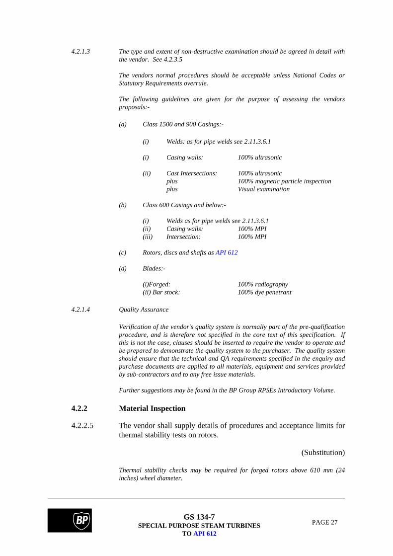
4.2.1.3 The type and extent of non-destructive examination should be agreed in detail withthe vendor. See 4.2.3.5
The vendors normal procedures should be acceptable unless National Codes orStatutory Requirements overrule.
The following guidelines are given for the purpose of assessing the vendorsproposals:-
(a) Class 1500 and 900 Casings:-
(i) Welds: as for pipe welds see 2.11.3.6.1
(i) Casing walls: 100% ultrasonic
(ii) Cast Intersections: 100% ultrasonicplus 100% magnetic particle inspectionplus Visual examination
(b) Class 600 Casings and below:-
(i) Welds as for pipe welds see 2.11.3.6.1(ii) Casing walls: 100% MPI(iii) Intersection: 100% MPI
(c) Rotors, discs and shafts as API 612
(d) Blades:-
(i)Forged: 100% radiography(ii) Bar stock: 100% dye penetrant
4.2.1.4 Quality Assurance
Verification of the vendor's quality system is normally part of the pre-qualificationprocedure, and is therefore not specified in the core text of this specification. Ifthis is not the case, clauses should be inserted to require the vendor to operate andbe prepared to demonstrate the quality system to the purchaser. The quality systemshould ensure that the technical and QA requirements specified in the enquiry andpurchase documents are applied to all materials, equipment and services providedby sub-contractors and to any free issue materials.
Further suggestions may be found in the BP Group RPSEs Introductory Volume.
4.2.2 Material Inspection
4.2.2.5 The vendor shall supply details of procedures and acceptance limits forthermal stability tests on rotors.
(Substitution)
Thermal stability checks may be required for forged rotors above 610 mm (24inches) wheel diameter.

GS 134-7SPECIAL PURPOSE STEAM TURBINES
TO API 612
PAGE 28
The checks are designed to eliminate asymmetric residual stresses arising from theforging process and check that the rotor is free from temperature dependentbending resulting from permanent asymmetric circumferential variation inproperties.
The checks are done by rotating the rotor in an oven at a temperature just below itstempering temperature. The rotor eccentricity is measured at various points and thecheck continued until no further changes in eccentricity are detected.
The check is repeated at a lower temperature (but above the maximum operatingtemperature). The cold to cold eccentricity change is noted and must not exceed aprescribed limit. The check is repeated until the limit is satisfied. This shouldideally be zero.
The cold to hot eccentricity change is also noted. This is a particularly criticalparameter as it indicates the presence of temperature dependent bending, which,depending upon the rotor parameters and operating speeds, may lead to itsrejection. Ideally this change should be zero. The changes must not be confusedwith effects caused by differing surface emissivities, which should be transient anddisappear once the rotor has soaked for a sufficient time. The check must berepeated to demonstrate this effect has corrected itself.
4.2.3 Mechanical Inspection
4.2.3.5 BP may require demonstration of the quality system, but this may be waived if thesystem has been verified recently by an accreditation scheme acceptable to BP.
4.3 Testing
4.3.1 General
4.3.1.1 The following tests are required:-
(a) Hydrostatic test in accordance with 4.3.2. of API 612.
(b) Mechanical running test in accordance with 4.3.3.
See 4.3.4 for requirements for Optional Tests
(Substitution)4.3.3 Mechanical Running Test
4.3.3.1.9 Shaft runout at the location of each proximity probe shall be measuredimmediately before the mechanical running test.
(Addition)
4.3.3.3.2 The sweep of vibration amplitudes versus frequencies shall additionallybe carried out at the minimum operating speed and at the normaloperating speed.

GS 134-7SPECIAL PURPOSE STEAM TURBINES
TO API 612
PAGE 29
Journal orbits shall be recorded at maximum continuous speeds.Vibration phase readings shall be related to the fixed shaft phasereference.
(Addition)
4.3.3.3.5 & 4.3.3.3.6
Tape recordings enable detail analysis of phase, amplitude and spectrum to bemade subsequent to the testing, and also to capture transient events, e.g. runup,coast down, or any unscheduled happening during the tests.
Copies of these tapes are not normally requested.
4.3.3.3.7 During the 4 hour test, lube-oil and control oil temperatures shall beheld for at least half an hour at the value corresponding to the minimumallowable viscosity and half an hour at the values corresponding to themaximum allowable viscosity. Under both conditions shaft vibrationsshall be measured in accordance with 4.3.3.3.2 checking in particularfor oil film instabilities.
(Addition)
The purpose of varying the oil supply temperature and hence the oil viscosity is to:-
(a) Ensure that the rotor is stable at the minimum viscosity (high temperatureoil) and also that the temperatures are acceptable.
(b) Ensure that bearing temperatures (particularly the thrust bearing) areacceptable with maximum viscosity (low temperature oil).
4.3.4 Optional Tests
4.3.4.1 A shop performance test is possible when there is steam available at the requiredquality and in the required quantity, together with the means to load the turbine.
Where steam consumption is important and guarantees, with penalties, have beengiven by the vendor, then a test is essential. In the absence of shop facilities sitetesting can be arranged. This requires provision for the accurate measurement ofsteam conditions, flow and load. This will need to be considered at the designstage.
4.3.4.2 Wherever the shop facilities permit, a complete unit test should be specified. Thecomplete unit test may be performed in place of separate tests. However, this maynot always be justified; the time required for an additional complete unit test maybe more valuable during plant pre-commissioning on site provided that the drivenunit can be operated (say the compressor running on air). There is therefore aneed to evaluate the benefit of a complete unit test in addition to the usualmechanical tests. Different constraints will be added for offshore activity.
Torsional tests are required only where analysis leads to concern and the need todetermine natural frequencies and damping. When these are required they shouldbe carried out in the manufacturers works on the complete train.

GS 134-7SPECIAL PURPOSE STEAM TURBINES
TO API 612
PAGE 30
4.3.4.3 Shop sound level tests have diminishing validity as steam conditions and loaddeviate from site conditions.
Where a valid test can be made the 'sound intensity' technique is recommended.(See 2.1.11). The services of a specialist consultant is usually required for thispurpose.
4.3.4.4 Auxiliary systems should be tested wherever shop facilities permit.
4.3.4.5 Internal inspection should only be made if the testing has given rise to concern forthe internals.
4.3.4.6 The requirement to inspect coupling hubs has not arisen on past BP contracts. Thefact that API notes this as an option implies there have been problems elsewhere.
The vendor's experience should be examined or integral coupling flanges used.
4.3.4.7 Additional tests/checks may include:-
(a) Coupling windage checks
(b) Thrust load checks
(c) Governor response checks
i) Injecting a signal into the speed control loop and measuring theresponse of control valves.
(ii) Full load rejection.
(d) Trip valve response checks
(e) Rotor to stator differential expansion check
(f) Casing expansion checks
(g) Pipe load distortion checks
(h) Hot run-up check
5. VENDOR'S DATA
5.1 Proposals
The following information shall be provided in addition to that listed:-
(a) Blading limitations referred to in 2.6.3.5.
(b) Potential maximum power.
(c) Approximate values for lateral critical speeds.

GS 134-7SPECIAL PURPOSE STEAM TURBINES
TO API 612
PAGE 31
(d) Typical sound pressure levels.
(e) A description of the quality system required by clause 4.2.1.4.
(Addition)
5.1.g.3 Failure can originate at the trailing edge of blading, especially if the edge or thetransition to the root is sharp. The vendor should be required to give details ofblade configuration in these areas.
5.2 Contract Data
5.2.5 Data
5.2.5.2d The vendor shall submit certified copies of test data to the purchaserbefore shipment.
(Qualification)
5.2.5.2f The vendor shall supply calculated rotor response reports.
(Substitution)
GS 134-7SPECIAL PURPOSE STEAM TURBINES
TO API 612
PAGE 32
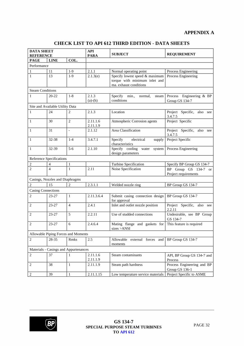
APPENDIX A
CHECK LIST TO API 612 THIRD EDITION - DATA SHEETS
DATA SHEETREFERENCE
APIPARA SUBJECT REQUIREMENT
PAGE LINE COL.
Performance
1 11 1-9 2.1.1 Normal operating point Process Engineering1 13 1-9 2.1.3(e) Specify lowest speed & maximum
torque with minimum inlet andma. exhaust conditions
Process Engineering
Steam Conditions
1 20-22 1-8 2.1.3(a)-(h)
Specify min., normal, steamconditions
Process Engineering & BPGroup GS 134-7
Site and Available Utility Data
1 24 2 2.1.3 Location Project Specific, also see3.4.7.5
1 30 2 2.11.1.62.11.1.9
Atmospheric Corrosion agents Project Specific
1 31 - 2.1.12 Area Classification Project Specific, also see3.4.7.5
1 32-38 1-4 3.4.7.1 Specify electrical supplycharacteristics
Project Specific
1 32-39 5-6 2.1.10 Specify cooling water systemdesign parameters
Process Engineering
Reference Specifications
2 4 1 Turbine Specification Specify BP Group GS 134-72 4 1 2.11 Noise Specification BP Group GS 134-7 or
Project requirements
Casings, Nozzles and Diaphragms
2 15 2 2.3.1.1 Welded nozzle ring BP Group GS 134-7
Casing Connections
2 23-27 1 2.11.3.6.4 Submit casing connection designfor approval
BP Group GS 134-7
2 23-27 4 2.4.1 Inlet and outlet nozzle position Project Specific, also see2.2.11
2 23-27 5 2.2.11 Use of studded connections Undesirable, see BP GroupGS 134-7
2 23-27 6 2.4.6.4 Mating flange and gaskets forsizes >ANSI
This feature is required
Allowable Piping Forces and Moments
2 28-35 Rmks 2.5 Allowable external forces andmoments
BP Group GS 134-7
Materials - Casings and Appurtenances
2 37 1 2.11.1.62.11.1.9
Steam contaminants API, BP Group GS 134-7 andProcess
2 38 1 2.11.1.9 Steam path hardness Process Engineering and BPGroup GS 136-1
2 39 1 2.11.1.15 Low temperature service materials Project Specific to ASME
GS 134-7SPECIAL PURPOSE STEAM TURBINES
TO API 612
PAGE 33
DATA SHEETREFERENCE
APIPARA
SUBJECT REQUIREMENT
PAGE LINE COL.
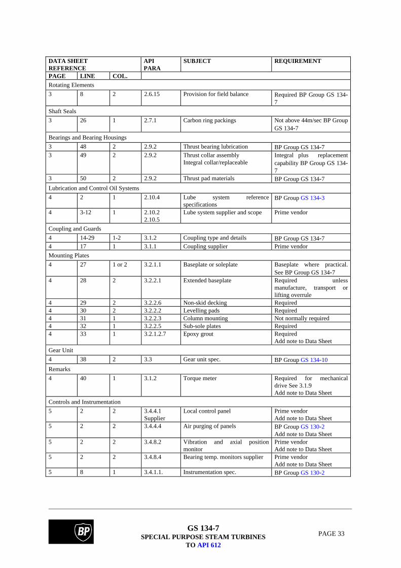
Rotating Elements
3 8 2 2.6.15 Provision for field balance Required BP Group GS 134-7
Shaft Seals
3 26 1 2.7.1 Carbon ring packings Not above 44m/sec BP GroupGS 134-7
Bearings and Bearing Housings
3 48 2 2.9.2 Thrust bearing lubrication BP Group GS 134-73 49 2 2.9.2 Thrust collar assembly
Integral collar/replaceableIntegral plus replacementcapability BP Group GS 134-7
3 50 2 2.9.2 Thrust pad materials BP Group GS 134-7Lubrication and Control Oil Systems
4 2 1 2.10.4 Lube system referencespecifications
BP Group GS 134-3
4 3-12 1 2.10.22.10.5
Lube system supplier and scope Prime vendor
Coupling and Guards
4 14-29 1-2 3.1.2 Coupling type and details BP Group GS 134-74 17 1 3.1.1 Coupling supplier Prime vendor
Mounting Plates
4 27 1 or 2 3.2.1.1 Baseplate or soleplate Baseplate where practical.See BP Group GS 134-7
4 28 2 3.2.2.1 Extended baseplate Required unlessmanufacture, transport orlifting overrule
4 29 2 3.2.2.6 Non-skid decking Required4 30 2 3.2.2.2 Levelling pads Required4 31 1 3.2.2.3 Column mounting Not normally required4 32 1 3.2.2.5 Sub-sole plates Required4 33 1 3.2.1.2.7 Epoxy grout Required
Add note to Data Sheet
Gear Unit
4 38 2 3.3 Gear unit spec. BP Group GS 134-10
Remarks
4 40 1 3.1.2 Torque meter Required for mechanicaldrive See 3.1.9Add note to Data Sheet
Controls and Instrumentation
5 2 2 3.4.4.1Supplier
Local control panel Prime vendorAdd note to Data Sheet
5 2 2 3.4.4.4 Air purging of panels BP Group GS 130-2Add note to Data Sheet
5 2 2 3.4.8.2 Vibration and axial positionmonitor
Prime vendorAdd note to Data Sheet
5 2 2 3.4.8.4 Bearing temp. monitors supplier Prime vendorAdd note to Data Sheet
5 8 1 3.4.1.1. Instrumentation spec. BP Group GS 130-2

GS 134-7SPECIAL PURPOSE STEAM TURBINES
TO API 612
PAGE 34
DATA SHEETREFERENCE
APIPARA
SUBJECT REQUIREMENT
PAGE LINE COL.
Protective Devices
5 12-21 1 & 2 2.2.5 Exhaust relief valves (Exhaust& Extract)
Supplier - Project Data -processAlso see 2.2.4 and 3.4.5.7
5 12-21 3 2.3.7 Sentinel warning valve Required5 12-21 4 3.4.3.9 Vacuum breaker Not normally required5 12-21 5 3.4.3.8 Non-return valve Supplier - Project Data -
Process Engineering
Trip and Throttle Valves
5 31 1 or 2 3.4.3.3 Trip valve manual exer. Required (see 3.4.3.3)
Turning Gear
6 33-44 1 3.9.1 Turning gear BP Group GS 134-7
Miscellaneous
6 34 2 2.1.6 Vendor review of piping andfoundation drg.
Required
6 36 2 2.1.6 Vendor witness initialalignment check
Required
6 39 2 3.2.2.2 Optical alignment flats Required
Governor
7 1 1 3.4.2.6 NEMA class of governor API 6127 1 2 3.4.2.2 No. of governor speed pickups 2 per API 6127 2-30
2-611
3.4.2.13.4.2.2
Speed governor type andcharacteristics
Type-Electronic to BPGroup GS 134-7Characteristics Project
7 8 2 3.4.2.11 Hand Valves Process Engineering & BPGroup GS 134-7
Overspeed Trap
7 10-22 2 3.4.3.6 Overspeed trip BP Group GS 134-7
Gland Sealing and Vacuum System
7 42-50 1 3.7.1 Insulation and jacketing BP Group GS 134-7
Inspection and Testing General
8 306 1 4.1.4 Extent of shop inspect BP Group GS 134-7 andthis checklist
Inspection and Material Testing
8 8 1 4.2.1.1e Final assembly clearancerecords
Required
8 9-20 1 2.11.364.1.34.2.1.3
Special material inspec. andtesting requirements
BP Group GS 134-7
8 21 1 4.2.2.5 Heat stability BP Group GS 134-78 22 1 4.2.3.3 Cleanliness check Required
Witness8 23 1 4.2.3.4 Hardness check For NACE mat only. Test
certs required8 24 1 4.3.2 Hydro tests Required
Witness

GS 134-7SPECIAL PURPOSE STEAM TURBINES
TO API 612
PAGE 35
DATA SHEETREFERENCE
APIPARA
SUBJECT REQUIREMENT
PAGE LINE COL.
Inspection and Material Testing (Cont'd)
8 25 1 None Blade shaker tests Not normally required - Testcerts. (see BP Group GS 134-7 2.6.3.1)
8 27 1 2.8.5 Low speed balance RequiredWitness
8 28 1 1.8.6.4 High speed balance Required where facilitiesexistWitness
8 29 1 4.4.3 Final surface inspection Required8 30 1 4.4.1 Crating inspection Required
Witness8 31 1 None Spare rotor fit Required
Witness
Painting
8 32 1 None Painting specification Vendor std. to Projectapproval
Shipment
8 36-42 1 4.4.14.4.3.10
Shipment Project Specific
Mechanical Running Tests
8 4 2 4.4.3 Contract rotor RequiredWitness
8 5 2 4.4.3 Spare rotor RequiredWitness
8 6 2 4.4.3 With job coupling Required8 7 2 4.4.3 Test tape required Required8 8 2 4.4.3 Test tape to purchaser Project Specific
Optional Tests
8 11 2 4.3.4 Optional tests BP Group GS 134-78 13 2 4.3.4.1 Performance test Required when facilities
permit - see BP Group GS134-7Witness
9 14 2 4.3.4.2 Complete unit test Required when facilitiespermit - see BP Group GS134-7Witness
8 15 2 4.3.4.2 Torsional measurement Not normally required (seeBP Group GS 134-7)
8 16 2 4.3.4.32.1.11
Sound level RequiredWitness
8 18 2 4.3.4.4 T and T valve RequiredWitness
8 19 2 4.3.4.4 Gland sealing system RequiredWitness
8 20 2 4.3.4.4 Gland vacuum system RequiredWitness
8 21 2 4.3.4.4 Lube oil system RequiredWitness

GS 134-7SPECIAL PURPOSE STEAM TURBINES
TO API 612
PAGE 36
DATA SHEETREFERENCE
APIPARA
SUBJECT REQUIREMENT
PAGE LINE COL.
Optional Tests (Cont'd)
8 22 2 4.3.4.4 Relief valves Bench testWitness
8 25 2 4.3.4.5 Casing internal inspect Required if test causesconcern BP Group GS134-7
8 26 2 4.3.4.6 Coupling to shaft fit Match marking requiredWitness
8 27 2 None Turning gear Required when suppliedWitness
8 28 2 4.3.4.7 Additional tests BP Group GS 134-7

GS 134-7SPECIAL PURPOSE STEAM TURBINES
TO API 612
PAGE 37
APPENDIX F
DEFINITIONS AND ABBREVIATIONS
Definitions
Standardised definitions may be found in the BP Group RPSEs Introductory Volume.
Abbreviations
AGMA American Gear Manufacturers AssociationANSI American National Standards InstituteAPI American Petroleum InstituteASME American Society of Mechanical EngineersBS British StandardEEMUA Engineering Equipment and Materials Users' AssociationEP Extreme PressureISO International Organisation for Standardisation

GS 134-7SPECIAL PURPOSE STEAM TURBINES
TO API 612
PAGE 38
APPENDIX G
LIST OF REFERENCED DOCUMENTS
A reference invokes the latest published issue or amendment unless stated otherwise.
Referenced standards may be replaced by equivalent standards that are internationally orotherwise recognised provided that it can be shown to the satisfaction of the purchaser'sprofessional engineer that they meet or exceed the requirements of the referenced standards.
American
AGMA 421.06 Practice for High Speed Helical and Herring Bone Gear Units
API 612 Special-Purpose Steam Turbines for Refinery Services(to be replaced by ISO 10437)
API 613 Special Purpose Gear Units for Refinery Services(to be replaced by ISO 13711)
API 614 Lubrication, Shaft-Sealing and Control-Oil Systems for SpecialPurpose Applications(to be replaced by ISO 10438)
API 670 Vibration, Axial-Position, and Bearing-Temperature MonitoringSystems.
BP Group Documents
BP Group GS 130-2 Instrumentation for Rotating Machinery.(replaces BP Std 128)
BP Group GS 134-3 Lubrication, Shaft Sealing and Control Oil Systems for SpecialPurpose Applications to API 614(replaces BP Std 190)
BP Group GS 134-10 Special Purpose Gear Units to API 613.(replaces BP Std 202)
EEMUA
EEMUA Publication No. 140 Noise Procedure Specification(replaces OCMA specification NWG-1).


![[XLS]dev.eiopa.europa.eu · Web view2 6 6 7/7/2014 8 7/7/2014 1 7 7 7/7/2014 9 7/7/2014 1 8 8 7/7/2014 10 7/7/2014 1 9 9 7/7/2014 11 7/7/2014 1 10 10 7/7/2014 12 7/7/2014 1 11 11](https://img.pdfslide.net/doc/110x75/5ae5800d7f8b9a8b2b8bf1f3/xlsdeveiopa-view2-6-6-772014-8-772014-1-7-7-772014-9-772014-1-8-8-772014.jpg)