Embed Size (px)
Citation preview
GS2 Series DrivesU s e r M a n u a l
230V Input: 0.5 - 7.5 hp
460V Input: 1.0 - 10 hp
115V Input: 0.25 - 1.0 hp
575V Input: 1.0 - 10 hp

WARNING Thank you for purchasing automation equipment from Automationdirect.com®, doing business asAutomationDirect. We want your new automation equipment to operate safely. Anyone who installsor uses this equipment should read this publication (and any other relevant publications) beforeinstalling or operating the equipment.
To minimize the risk of potential safety problems, you should follow all applicable local and nationalcodes that regulate the installation and operation of your equipment. These codes vary from area toarea and usually change with time. It is your responsibility to determine which codes should befollowed, and to verify that the equipment, installation, and operation is in compliance with thelatest revision of these codes.
At a minimum, you should follow all applicable sections of the National Fire Code, NationalElectrical Code, and the codes of the National Electrical Manufacturer's Association (NEMA). Theremay be local regulatory or government offices that can also help determine which codes andstandards are necessary for safe installation and operation.
Equipment damage or serious injury to personnel can result from the failure to follow all applicablecodes and standards. We do not guarantee the products described in this publication are suitable foryour particular application, nor do we assume any responsibility for your product design,installation, or operation.
Our products are not fault-tolerant and are not designed, manufactured or intended for use or resaleas on-line control equipment in hazardous environments requiring fail-safe performance, such as inthe operation of nuclear facilities, aircraft navigation or communication systems, air traffic control,direct life support machines, or weapons systems, in which the failure of the product could leaddirectly to death, personal injury, or severe physical or environmental damage ("High RiskActivities"). AutomationDirect specifically disclaims any expressed or implied warranty of fitness forHigh Risk Activities.
For additional warranty and safety information, see the Terms and Conditions section of our catalog.If you have any questions concerning the installation or operation of this equipment, or if you needadditional information, please call us at 770-844-4200.
This publication is based on information that was available at the time it was printed. AtAutomationDirect we constantly strive to improve our products and services, so we reserve the rightto make changes to the products and/or publications at any time without notice and without anyobligation. This publication may also discuss features that may not be available in certain revisions ofthe product.
TrademarksThis publication may contain references to products produced and/or offered by other companies.The product and company names may be trademarked and are the sole property of their respectiveowners. AutomationDirect disclaims any proprietary interest in the marks and names of others.
Copyright 2004, Automationdirect.com® IncorporatedAll Rights Reserved
No part of this manual shall be copied, reproduced, or transmitted in any way without the prior,written consent of Automationdirect.com® Incorporated. AutomationDirect retains the exclusiverights to all information included in this document.
AVERTISSEMENT Nous vous remercions d'avoir acheté l'équipement d'automatisation de Automationdirect.com®, enfaisant des affaires comme AutomationDirect. Nous tenons à ce que votre nouvel équipementd'automatisation fonctionne en toute sécurité. Toute personne qui installe ou utilise cet équipementdoit lire la présente publication (et toutes les autres publications pertinentes) avant de l'installer oude l'utiliser.
Afin de réduire au minimum le risque d'éventuels problèmes de sécurité, vous devez respecter tousles codes locaux et nationaux applicables régissant l'installation et le fonctionnement de votreéquipement. Ces codes diffèrent d'une région à l'autre et, habituellement, évoluent au fil du temps. Ilvous incombe de déterminer les codes à respecter et de vous assurer que l'équipement, l'installationet le fonctionnement sont conformes aux exigences de la version la plus récente de ces codes.
Vous devez, à tout le moins, respecter toutes les sections applicables du Code national deprévention des incendies, du Code national de l'électricité et des codes de la National ElectricalManufacturer's Association (NEMA). Des organismes de réglementation ou des servicesgouvernementaux locaux peuvent également vous aider à déterminer les codes ainsi que les normesà respecter pour assurer une installation et un fonctionnement sûrs.
L'omission de respecter la totalité des codes et des normes applicables peut entraîner des dommagesà l'équipement ou causer de graves blessures au personnel. Nous ne garantissons pas que les produitsdécrits dans cette publication conviennent à votre application particulière et nous n'assumons aucuneresponsabilité à l'égard de la conception, de l'installation ou du fonctionnement de votre produit.
Nos produits ne sont pas insensibles aux défaillances et ne sont ni conçus ni fabriqués pourl'utilisation ou la revente en tant qu'équipement de commande en ligne dans des environnementsdangereux nécessitant une sécurité absolue, par exemple, l'exploitation d'installations nucléaires, lessystèmes de navigation aérienne ou de communication, le contrôle de la circulation aérienne, leséquipements de survie ou les systèmes d'armes, pour lesquels la défaillance du produit peutprovoquer la mort, des blessures corporelles ou de graves dommages matériels ouenvironnementaux («activités à risque élevé»). La société AutomationDirect nie toute garantieexpresse ou implicite d'aptitude à l'emploi en ce qui a trait aux activités à risque élevé.
Pour des renseignements additionnels touchant la garantie et la sécurité, veuillez consulter la sectionModalités et conditions de notre documentation. Si vous avez des questions au sujet de l'installationou du fonctionnement de cet équipement, ou encore si vous avez besoin de renseignementssupplémentaires, n'hésitez pas à nous téléphoner au 770-844-4200.
Cette publication s'appuie sur l'information qui était disponible au moment de l'impression. À lasociété AutomationDirect, nous nous efforçons constamment d'améliorer nos produits et services.C'est pourquoi nous nous réservons le droit d'apporter des modifications aux produits ou auxpublications en tout temps, sans préavis ni quelque obligation que ce soit. La présente publicationpeut aussi porter sur des caractéristiques susceptibles de ne pas être offertes dans certaines versionsrévisées du produit.
Marques de commerceLa présente publication peut contenir des références à des produits fabriqués ou offerts par d'autresentreprises. Les désignations des produits et des entreprises peuvent être des marques de commerceet appartiennent exclusivement à leurs propriétaires respectifs. AutomationDirect nie tout intérêtdans les autres marques et désignations.
Copyright 2004, Automationdirect.com® IncorporatedTous droits réservés
Nulle partie de ce manuel ne doit être copiée, reproduite ou transmise de quelque façon que ce soitsans le consentement préalable écrit de la société Automationdirect.com® Incorporated.AutomationDirect conserve les droits exclusifs à l'égard de tous les renseignements contenus dans leprésent document.
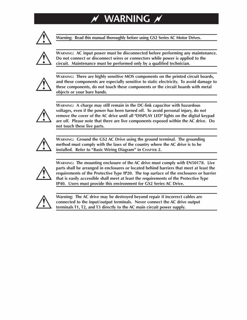
WARNING
Warning: The AC drive may be destroyed beyond repair if incorrect cables areconnected to the input/output terminals. Never connect the AC drive outputterminals T1, T2, and T3 directly to the AC main circuit power supply.
WARNING: The mounting enclosure of the AC drive must comply with EN50178. Liveparts shall be arranged in enclosures or located behind barriers that meet at least therequirements of the Protective Type IP20. The top surface of the enclosures or barrierthat is easily accessible shall meet at least the requirements of the Protective TypeIP40. Users must provide this environment for GS2 Series AC Drive.
WARNING: Ground the GS2 AC Drive using the ground terminal. The groundingmethod must comply with the laws of the country where the AC drive is to beinstalled. Refer to “Basic Wiring Diagram” in CHAPTER 2.
WARNING: A charge may still remain in the DC-link capacitor with hazardousvoltages, even if the power has been turned off. To avoid personal injury, do notremove the cover of the AC drive until all "DISPLAY LED" lights on the digital keypadare off. Please note that there are live components exposed within the AC drive. Donot touch these live parts.
WARNING: There are highly sensitive MOS components on the printed circuit boards,and these components are especially sensitive to static electricity. To avoid damage tothese components, do not touch these components or the circuit boards with metalobjects or your bare hands.
WARNING: AC input power must be disconnected before performing any maintenance.Do not connect or disconnect wires or connectors while power is applied to thecircuit. Maintenance must be performed only by a qualified technician.
Warning: Read this manual thoroughly before using GS2 Series AC Motor Drives.
Please include the Manual Number and the Manual Issue, both shown below, whencommunicating with Technical Support regarding this publication.
Manual Number: GS2-M
Issue: First Edition, Revision C
Issue Date: 12/2006
GS2 SERIES AC DRIVE
U S E R M A N U A L
Publication History
Issue Date Description of Changes
First Edition 6/07/02 Original
First Edition, Revision A 6/30/03Made minor changes throughout.Update for Firmware Version 1.04Added parameter 7.00 (PID) functionality.
First Edition, Revision B 1/28/05 Added 115V drives; Made minor changes throughout.
First Edition, Revision C 12/2006
Added 575V drives and accessories; Added Ch1 Drives Purposesection; Added short circuit withstand specifications and notes;Changed Ch5 DL PLC control program example; Added new AppxBPLC analog modules; Miscellaneous clarification revisions throughout.
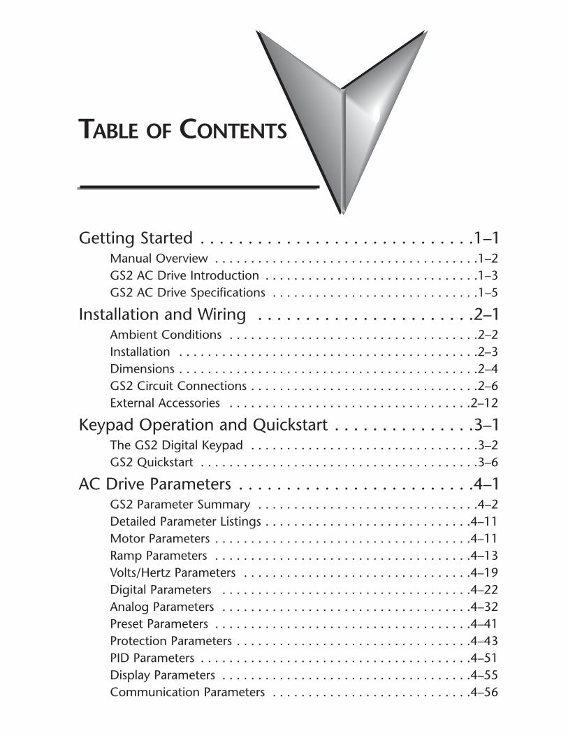
TABLE OF CONTENTS
Getting Started . . . . . . . . . . . . . . . . . . . . . . . . . . . . .1–1Manual Overview . . . . . . . . . . . . . . . . . . . . . . . . . . . . . . . . . . . . .1–2GS2 AC Drive Introduction . . . . . . . . . . . . . . . . . . . . . . . . . . . . . .1–3GS2 AC Drive Specifications . . . . . . . . . . . . . . . . . . . . . . . . . . . . .1–5
Installation and Wiring . . . . . . . . . . . . . . . . . . . . . . .2–1Ambient Conditions . . . . . . . . . . . . . . . . . . . . . . . . . . . . . . . . . . .2–2Installation . . . . . . . . . . . . . . . . . . . . . . . . . . . . . . . . . . . . . . . . . .2–3Dimensions . . . . . . . . . . . . . . . . . . . . . . . . . . . . . . . . . . . . . . . . . .2–4GS2 Circuit Connections . . . . . . . . . . . . . . . . . . . . . . . . . . . . . . . .2–6External Accessories . . . . . . . . . . . . . . . . . . . . . . . . . . . . . . . . . .2–12
Keypad Operation and Quickstart . . . . . . . . . . . . . . .3–1The GS2 Digital Keypad . . . . . . . . . . . . . . . . . . . . . . . . . . . . . . . .3–2GS2 Quickstart . . . . . . . . . . . . . . . . . . . . . . . . . . . . . . . . . . . . . . .3–6
AC Drive Parameters . . . . . . . . . . . . . . . . . . . . . . . . .4–1GS2 Parameter Summary . . . . . . . . . . . . . . . . . . . . . . . . . . . . . . .4–2Detailed Parameter Listings . . . . . . . . . . . . . . . . . . . . . . . . . . . . .4–11Motor Parameters . . . . . . . . . . . . . . . . . . . . . . . . . . . . . . . . . . . .4–11Ramp Parameters . . . . . . . . . . . . . . . . . . . . . . . . . . . . . . . . . . . .4–13Volts/Hertz Parameters . . . . . . . . . . . . . . . . . . . . . . . . . . . . . . . .4–19Digital Parameters . . . . . . . . . . . . . . . . . . . . . . . . . . . . . . . . . . .4–22Analog Parameters . . . . . . . . . . . . . . . . . . . . . . . . . . . . . . . . . . .4–32Preset Parameters . . . . . . . . . . . . . . . . . . . . . . . . . . . . . . . . . . . .4–41Protection Parameters . . . . . . . . . . . . . . . . . . . . . . . . . . . . . . . . .4–43PID Parameters . . . . . . . . . . . . . . . . . . . . . . . . . . . . . . . . . . . . . .4–51Display Parameters . . . . . . . . . . . . . . . . . . . . . . . . . . . . . . . . . . .4–55Communication Parameters . . . . . . . . . . . . . . . . . . . . . . . . . . . .4–56
Table of Contents
GS2 Series AC Drive User Manualii
GS2 Modbus Communications . . . . . . . . . . . . . . . . .5–1Communication Parameters Summary . . . . . . . . . . . . . . . . . . . . .5–2GS2 Parameter Memory Addresses . . . . . . . . . . . . . . . . . . . . . . . .5–4GS2 Status Addresses . . . . . . . . . . . . . . . . . . . . . . . . . . . . . . . . . .5–9Communicating with DirectLogic PLCs . . . . . . . . . . . . . . . . . . . .5–12Communicating with Third-party Devices . . . . . . . . . . . . . . . . . .5–30
Maintenance and Troubleshooting . . . . . . . . . . . . . .6–1Maintenance and Inspection . . . . . . . . . . . . . . . . . . . . . . . . . . . . .6–2Troubleshooting . . . . . . . . . . . . . . . . . . . . . . . . . . . . . . . . . . . . . .6–3
Accessories . . . . . . . . . . . . . . . . . . . . . . . . . . . . . . . .A–1Accessories Part Numbering . . . . . . . . . . . . . . . . . . . . . . . . . . . . .A–2Line Reactors . . . . . . . . . . . . . . . . . . . . . . . . . . . . . . . . . . . . . . . .A–2Braking Resistors . . . . . . . . . . . . . . . . . . . . . . . . . . . . . . . . . . . . . .A–8EMI Input Filters . . . . . . . . . . . . . . . . . . . . . . . . . . . . . . . . . . . . .A–10RF Filters . . . . . . . . . . . . . . . . . . . . . . . . . . . . . . . . . . . . . . . . . . .A–16Fuses and Fuse Kits . . . . . . . . . . . . . . . . . . . . . . . . . . . . . . . . . . .A–17GS-EDRV Ethernet Interface . . . . . . . . . . . . . . . . . . . . . . . . . . . .A–20GS Drive Configuration Software . . . . . . . . . . . . . . . . . . . . . . . .A–22Miscellaneous Accessories . . . . . . . . . . . . . . . . . . . . . . . . . . . . . .A–25
Using GS2 AC Drives with DirectLOGIC PLCs . . . . . .B–1Compatible DirectLOGIC PLCs and Modules . . . . . . . . . . . . . . . . .B–2Typical Connections to the GS2 Series AC Drive . . . . . . . . . . . . . .B–7
Index . . . . . . . . . . . . . . . . . . . . . . . . . . . . . . . . . . . . .I–1
GETTING STARTED 1CHAPTERCHAPTER
11CHAPTER
In This Chapter...
Manual Overview . . . . . . . . . . . . . . . . . . . . . . . . . .1–2Overview of this Publication . . . . . . . . . . . . . . . . . . . . . . . . . . . .1–2
Who Should Read This Manual . . . . . . . . . . . . . . . . . . . . . . . . . .1–2
Supplemental Publications . . . . . . . . . . . . . . . . . . . . . . . . . . . . .1–2
Technical Support . . . . . . . . . . . . . . . . . . . . . . . . . . . . . . . . . . . .1–2
Special Symbols . . . . . . . . . . . . . . . . . . . . . . . . . . . . . . . . . . . . .1–2
GS2 AC Drive Introduction . . . . . . . . . . . . . . . . . .1–3Purpose of AC Drives . . . . . . . . . . . . . . . . . . . . . . . . . . . . . . . . . .1–3
Unpacking . . . . . . . . . . . . . . . . . . . . . . . . . . . . . . . . . . . . . . . . . .1–3
Model Explanation: . . . . . . . . . . . . . . . . . . . . . . . . . . . . . . . . . . .1–3
Nameplate Information: . . . . . . . . . . . . . . . . . . . . . . . . . . . . . . .1–3
External Parts and Labels: . . . . . . . . . . . . . . . . . . . . . . . . . . . . . .1–4
GS2 AC Drive Specifications . . . . . . . . . . . . . . . . . .1–5
Chapter 1: Getting Started
GS2 Series AC Drive User Manual1–2
Manual Overview
Overview of this PublicationThe GS2 AC Drive User Manual describes the installation, configuration, andmethods of operation of the GS2 Series AC Drive.
Who Should Read This ManualThis manual contains important information for those who will install, maintain,and/or operate any of the GS2 Series AC Drives.
Supplemental PublicationsThe National Electrical Manufacturers Association (NEMA) publishes manydifferent documents that discuss standards for industrial control equipment.Global Engineering Documents handles the sale of NEMA documents. For moreinformation, you can contact Global Engineering Documents at:
15 Inverness Way EastEnglewood, CO 80112-57761-800-854-7179 (within the U.S.)303-397-7956 (international)www.global.ihs.com
NEMA documents that might assist with your AC drive systems are:
• Application Guide for AC Adjustable Speed Drive Systems• Safety Standards for Construction and Guide for Selection, Installation, and
Operation of Adjustable Speed Drive Systems.
Technical SupportBy Telephone: 770-844-4200
(Mon.-Fri., 9:00 a.m.-6:00 p.m. E.T.)On the Web: www.automationdirect.com
Our technical support group is glad to work with you in answering your questions. Ifyou cannot find the solution to your particular application, or, if for any reason youneed additional technical assistance, please call technical support at 770-844-4200.We are available weekdays from 9:00 a.m. to 6:00 p.m. Eastern Time.
We also encourage you to visit our web site where you can find technical andnon-technical information about our products and our company. Visit us atwww.automationdirect.com.
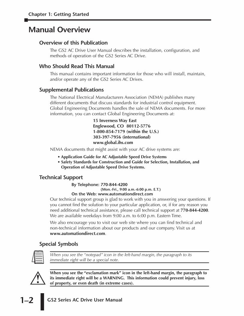
Special Symbols
When you see the “exclamation mark” icon in the left-hand margin, the paragraph toits immediate right will be a WARNING. This information could prevent injury, lossof property, or even death (in extreme cases).
When you see the “notepad” icon in the left-hand margin, the paragraph to itsimmediate right will be a special note.
GS2 Series AC Drive User Manual 1–3
GS2 AC Drive Introduction
Purpose of AC DrivesAC drives are generally known by many different names: Adjustable FrequencyDrives (AFD), Variable Frequency Drives (VFD), and Inverters. Drives are usedprimarily to vary the speed of three phase AC induction motors, and they alsoprovide non-emergency start and stop control, acceleration and deceleration, andoverload protection. By gradually accelerating the motor, drives can reduce theamount of motor startup inrush current.
AC drives function by converting incoming AC power to DC, which is thensynthesized back into three phase output power. The voltage and frequency ofthis synthesized output power is directly varied by the drive, where the frequencydetermines the speed of the three phase AC induction motor.
Drive Package ContentsAfter receiving the AC motor drive, please check for the following:
• Make sure that the package includes an AC drive, the GS2 Series AC Drive UserManual, and the GS2 Series AC Drive Quick Reference.
• Inspect the unit to insure it was not damaged during shipment.
• Make sure that the part number indicated on the nameplate corresponds with thepart number of your order.
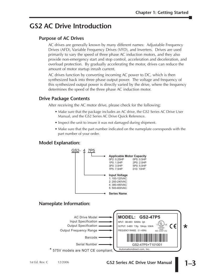
Model Explanation:
Nameplate Information:
MODEL: GS2-47P5INPUT: 380-480V 50/60Hz 3ph
OUTPUT: 0-480V 7.5hp 13Amps 9.9kVA
FREQUENCY RANGE: 0.1- 400Hz
GS2-47P5+T101001Automationdirect.com, Inc.
U®LC US
LISTED19XK
IND. CONT. EQ
AC Drive Model
Barcode
Output Frequency RangeOutput Specification
Input Specification
Serial Number
** 575V models are NOT CE compliant.
GS2- 4 7P5Applicable Motor Capacity0P2: 0.25HP 0P5: 0.5HP1P0: 1.0HP 2P0: 2.0HP3P0: 3.0HP 5P0: 5.0HP7P5: 7.5HP 010: 10HP Input Voltage1: 100-120VAC2: 200-240VAC4: 380-480VAC5: 500-600VAC
Series Name
Chapter 1: Getting Started
1st Ed. Rev. C 12/2006
Chapter 1: Getting Started
GS2 Series AC Drive User Manual1–4
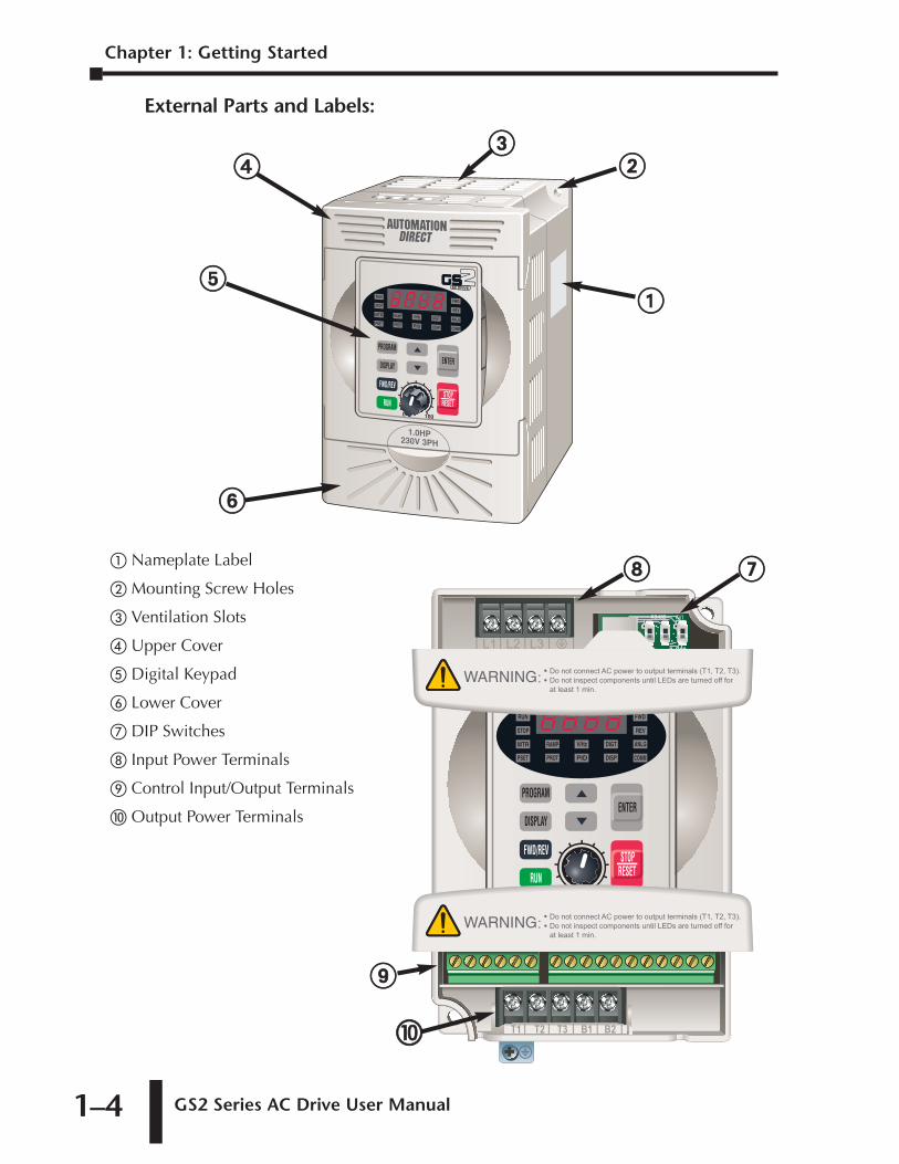
External Parts and Labels:
� Nameplate Label
� Mounting Screw Holes
� Ventilation Slots
� Upper Cover
� Digital Keypad
� Lower Cover
� DIP Switches
� Input Power Terminals
Control Input/Output Terminals
Output Power Terminals
��
��
��
��
��
��
��
��
GS2 Series AC Drive User Manual 1–5
GS2 AC Drive Specifications
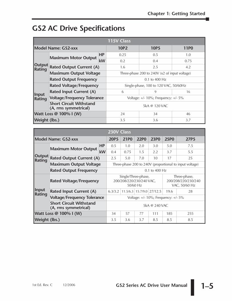
230V Class
Model Name: GS2-xxx 20P5 21P0 22P0 23P0 25P0 27P5
OutputRating
Maximum Motor OutputHP 0.5 1.0 2.0 3.0 5.0 7.5
kW 0.4 0.75 1.5 2.2 3.7 5.5
Rated Output Current (A) 2.5 5.0 7.0 10 17 25
Maximum Output Voltage Three-phase 200 to 240V (proportional to input voltage)
Rated Output Frequency 0.1 to 400 Hz
InputRating
Rated Voltage/FrequencySingle/Three-phase,
200/208/220/230/240 VAC,50/60 Hz
Three-phase,200/208/220/230/240
VAC, 50/60 Hz
Rated Input Current (A) 6.3/3.2 11.5/6.3 15.7/9.0 27/12.5 19.6 28
Voltage/Frequency Tolerance Voltage: +/- 10%; Frequency: +/- 5%
Short Circuit Withstand (A, rms symmetrical) 5kA @ 240 VAC
Watt Loss @ 100% I (W) 34 57 77 111 185 255
Weight (lbs.) 3.5 3.6 3.7 8.5 8.5 8.5
115V Class
Model Name: GS2-xxx 10P2 10P5 11P0
OutputRating
Maximum Motor OutputHP 0.25 0.5 1.0
kW 0.2 0.4 0.75
Rated Output Current (A) 1.6 2.5 4.2
Maximum Output Voltage Three-phase 200 to 240V (x2 of input voltage)
Rated Output Frequency 0.1 to 400 Hz
InputRating
Rated Voltage/Frequency Single-phase, 100 to 120 VAC, 50/60Hz
Rated Input Current (A) 6 9 16
Voltage/Frequency Tolerance Voltage: +/- 10%; Frequency: +/- 5%
Short Circuit Withstand (A, rms symmetrical) 5kA @ 120 VAC
Watt Loss @ 100% I (W) 24 34 46
Weight (lbs.) 3.5 3.6 3.7
Chapter 1: Getting Started
1st Ed. Rev. C 12/2006
Chapter 1: Getting Started
GS2 Series AC Drive User Manual1–6
GS2 AC Drive Specifications (continued)
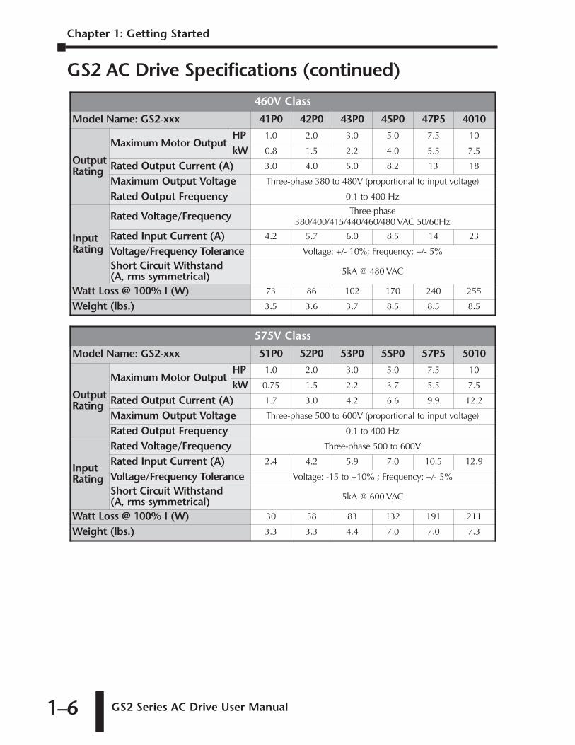
575V Class
Model Name: GS2-xxx 51P0 52P0 53P0 55P0 57P5 5010
OutputRating
Maximum Motor OutputHP 1.0 2.0 3.0 5.0 7.5 10
kW 0.75 1.5 2.2 3.7 5.5 7.5
Rated Output Current (A) 1.7 3.0 4.2 6.6 9.9 12.2
Maximum Output Voltage Three-phase 500 to 600V (proportional to input voltage)
Rated Output Frequency 0.1 to 400 Hz
InputRating
Rated Voltage/Frequency Three-phase 500 to 600V
Rated Input Current (A) 2.4 4.2 5.9 7.0 10.5 12.9
Voltage/Frequency Tolerance Voltage: -15 to +10% ; Frequency: +/- 5%
Short Circuit Withstand (A, rms symmetrical) 5kA @ 600 VAC
Watt Loss @ 100% I (W) 30 58 83 132 191 211
Weight (lbs.) 3.3 3.3 4.4 7.0 7.0 7.3
460V Class
Model Name: GS2-xxx 41P0 42P0 43P0 45P0 47P5 4010
OutputRating
Maximum Motor OutputHP 1.0 2.0 3.0 5.0 7.5 10
kW 0.8 1.5 2.2 4.0 5.5 7.5
Rated Output Current (A) 3.0 4.0 5.0 8.2 13 18
Maximum Output Voltage Three-phase 380 to 480V (proportional to input voltage)
Rated Output Frequency 0.1 to 400 Hz
InputRating
Rated Voltage/Frequency Three-phase380/400/415/440/460/480 VAC 50/60Hz
Rated Input Current (A) 4.2 5.7 6.0 8.5 14 23
Voltage/Frequency Tolerance Voltage: +/- 10%; Frequency: +/- 5%
Short Circuit Withstand (A, rms symmetrical) 5kA @ 480 VAC
Watt Loss @ 100% I (W) 73 86 102 170 240 255
Weight (lbs.) 3.5 3.6 3.7 8.5 8.5 8.5
GS2 Series AC Drive User Manual 1–7
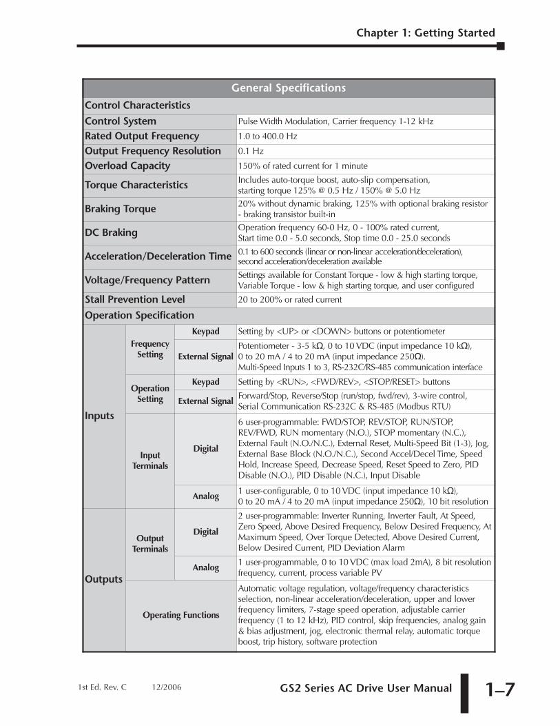
General Specifications
Control Characteristics
Control System Pulse Width Modulation, Carrier frequency 1-12 kHz
Rated Output Frequency 1.0 to 400.0 Hz
Output Frequency Resolution 0.1 Hz
Overload Capacity 150% of rated current for 1 minute
Torque Characteristics Includes auto-torque boost, auto-slip compensation, starting torque 125% @ 0.5 Hz / 150% @ 5.0 Hz
Braking Torque 20% without dynamic braking, 125% with optional braking resistor- braking transistor built-in
DC Braking Operation frequency 60-0 Hz, 0 - 100% rated current, Start time 0.0 - 5.0 seconds, Stop time 0.0 - 25.0 seconds
Acceleration/Deceleration Time 0.1 to 600 seconds (linear or non-linear acceleration/deceleration), second acceleration/deceleration available
Voltage/Frequency Pattern Settings available for Constant Torque - low & high starting torque,Variable Torque - low & high starting torque, and user configured
Stall Prevention Level 20 to 200% or rated current
Operation Specification
Inputs
FrequencySetting
Keypad Setting by <UP> or <DOWN> buttons or potentiometer
External SignalPotentiometer - 3-5 k, 0 to 10 VDC (input impedance 10 k),0 to 20 mA / 4 to 20 mA (input impedance 250).Multi-Speed Inputs 1 to 3, RS-232C/RS-485 communication interface
OperationSetting
Keypad Setting by <RUN>, <FWD/REV>, <STOP/RESET> buttons
External SignalForward/Stop, Reverse/Stop (run/stop, fwd/rev), 3-wire control, Serial Communication RS-232C & RS-485 (Modbus RTU)
InputTerminals
Digital
6 user-programmable: FWD/STOP, REV/STOP, RUN/STOP,REV/FWD, RUN momentary (N.O.), STOP momentary (N.C.),External Fault (N.O./N.C.), External Reset, Multi-Speed Bit (1-3), Jog,External Base Block (N.O./N.C.), Second Accel/Decel Time, SpeedHold, Increase Speed, Decrease Speed, Reset Speed to Zero, PIDDisable (N.O.), PID Disable (N.C.), Input Disable
Analog1 user-configurable, 0 to 10 VDC (input impedance 10 k), 0 to 20 mA / 4 to 20 mA (input impedance 250), 10 bit resolution
Outputs
OutputTerminals
Digital
2 user-programmable: Inverter Running, Inverter Fault, At Speed,Zero Speed, Above Desired Frequency, Below Desired Frequency, AtMaximum Speed, Over Torque Detected, Above Desired Current,Below Desired Current, PID Deviation Alarm
Analog1 user-programmable, 0 to 10 VDC (max load 2mA), 8 bit resolutionfrequency, current, process variable PV
Operating Functions
Automatic voltage regulation, voltage/frequency characteristicsselection, non-linear acceleration/deceleration, upper and lowerfrequency limiters, 7-stage speed operation, adjustable carrierfrequency (1 to 12 kHz), PID control, skip frequencies, analog gain& bias adjustment, jog, electronic thermal relay, automatic torqueboost, trip history, software protection
Chapter 1: Getting Started
1st Ed. Rev. C 12/2006
Chapter 1: Getting Started
GS2 Series AC Drive User Manual1–8
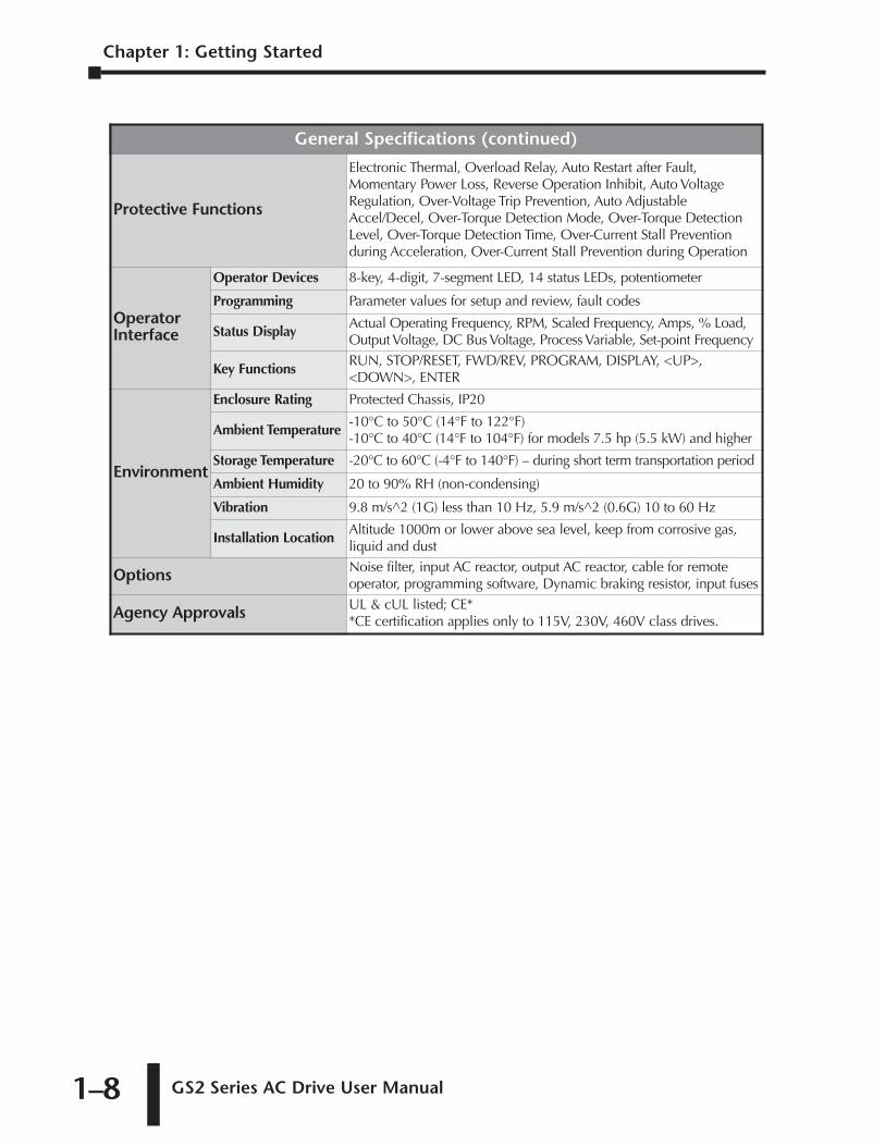
General Specifications (continued)
Protective Functions
Electronic Thermal, Overload Relay, Auto Restart after Fault,Momentary Power Loss, Reverse Operation Inhibit, Auto VoltageRegulation, Over-Voltage Trip Prevention, Auto AdjustableAccel/Decel, Over-Torque Detection Mode, Over-Torque DetectionLevel, Over-Torque Detection Time, Over-Current Stall Preventionduring Acceleration, Over-Current Stall Prevention during Operation
OperatorInterface
Operator Devices 8-key, 4-digit, 7-segment LED, 14 status LEDs, potentiometer
Programming Parameter values for setup and review, fault codes
Status DisplayActual Operating Frequency, RPM, Scaled Frequency, Amps, % Load,Output Voltage, DC Bus Voltage, Process Variable, Set-point Frequency
Key FunctionsRUN, STOP/RESET, FWD/REV, PROGRAM, DISPLAY, <UP>,<DOWN>, ENTER
Environment
Enclosure Rating Protected Chassis, IP20
Ambient Temperature-10°C to 50°C (14°F to 122°F) -10°C to 40°C (14°F to 104°F) for models 7.5 hp (5.5 kW) and higher
Storage Temperature -20°C to 60°C (-4°F to 140°F) – during short term transportation period
Ambient Humidity 20 to 90% RH (non-condensing)
Vibration 9.8 m/s^2 (1G) less than 10 Hz, 5.9 m/s^2 (0.6G) 10 to 60 Hz
Installation LocationAltitude 1000m or lower above sea level, keep from corrosive gas,liquid and dust
Options Noise filter, input AC reactor, output AC reactor, cable for remoteoperator, programming software, Dynamic braking resistor, input fuses
Agency Approvals UL & cUL listed; CE* *CE certification applies only to 115V, 230V, 460V class drives.
INSTALLATION
AND WIRING 2CHAPTERCHAPTER
22CHAPTER
In This Chapter...
Ambient Conditions . . . . . . . . . . . . . . . . . . . . . . . .2–2
Installation . . . . . . . . . . . . . . . . . . . . . . . . . . . . . . .2–3Minimum Clearances and AirFlow . . . . . . . . . . . . . . . . . . . . . . . .2–3
Dimensions . . . . . . . . . . . . . . . . . . . . . . . . . . . . . .2–4
GS2 Circuit Connections . . . . . . . . . . . . . . . . . . . .2–6Danger . . . . . . . . . . . . . . . . . . . . . . . . . . . . . . . . . . . . . . . . . . . .2–6
Main Circuit Wiring . . . . . . . . . . . . . . . . . . . . . . . . . . . . . . . . . . .2–8
Control Terminal Wiring . . . . . . . . . . . . . . . . . . . . . . . . . . . . . .2–10
Basic Wiring Diagram . . . . . . . . . . . . . . . . . . . . . . . . . . . . . . . .2–11
External Accessories . . . . . . . . . . . . . . . . . . . . . . .2–12
Chapter 2: Installation and Wiring
GS2 Series AC Drive User Manual2–2
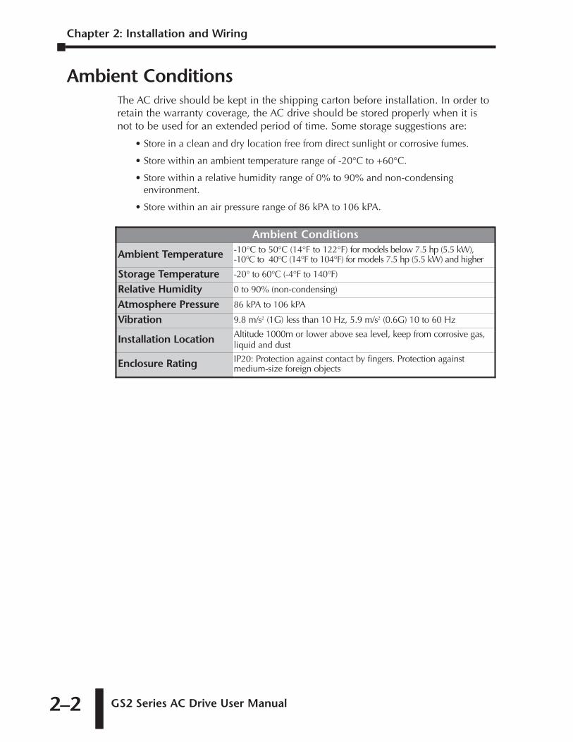
Ambient ConditionsThe AC drive should be kept in the shipping carton before installation. In order toretain the warranty coverage, the AC drive should be stored properly when it isnot to be used for an extended period of time. Some storage suggestions are:
• Store in a clean and dry location free from direct sunlight or corrosive fumes.
• Store within an ambient temperature range of -20°C to +60°C.
• Store within a relative humidity range of 0% to 90% and non-condensingenvironment.
• Store within an air pressure range of 86 kPA to 106 kPA.
Ambient Conditions
Ambient Temperature -10°C to 50°C (14°F to 122°F) for models below 7.5 hp (5.5 kW),-10°C to 40°C (14°F to 104°F) for models 7.5 hp (5.5 kW) and higher
Storage Temperature -20° to 60°C (-4°F to 140°F)
Relative Humidity 0 to 90% (non-condensing)
Atmosphere Pressure 86 kPA to 106 kPA
Vibration 9.8 m/s2 (1G) less than 10 Hz, 5.9 m/s2 (0.6G) 10 to 60 Hz
Installation Location Altitude 1000m or lower above sea level, keep from corrosive gas,liquid and dust
Enclosure Rating IP20: Protection against contact by fingers. Protection againstmedium-size foreign objects
GS2 Series AC Drive User Manual 2–3
Chapter 2: Installation and Wiring
1st Ed. Rev. C 12/2006
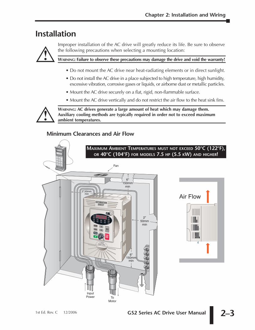
InstallationImproper installation of the AC drive will greatly reduce its life. Be sure to observethe following precautions when selecting a mounting location:
WARNING: Failure to observe these precautions may damage the drive and void the warranty!
• Do not mount the AC drive near heat-radiating elements or in direct sunlight.
• Do not install the AC drive in a place subjected to high temperature, high humidity,excessive vibration, corrosive gases or liquids, or airborne dust or metallic particles.
• Mount the AC drive securely on a flat, rigid, non-flammable surface.
• Mount the AC drive vertically and do not restrict the air flow to the heat sink fins.
WARNING: AC drives generate a large amount of heat which may damage them.Auxiliary cooling methods are typically required in order not to exceed maximumambient temperatures.
Minimum Clearances and Air Flow
6"150mm
min
6"150mm
min
2"50mm
min
2",50mmmin
Fan
InputPower To
Motor
Air Flow
MAXIMUM AMBIENT TEMPERATURES MUST NOT EXCEED 50°C (122°F),OR 40°C (104°F) FOR MODELS 7.5 HP (5.5 KW) AND HIGHER!
Chapter 2: Installation and Wiring
GS2 Series AC Drive User Manual2–4
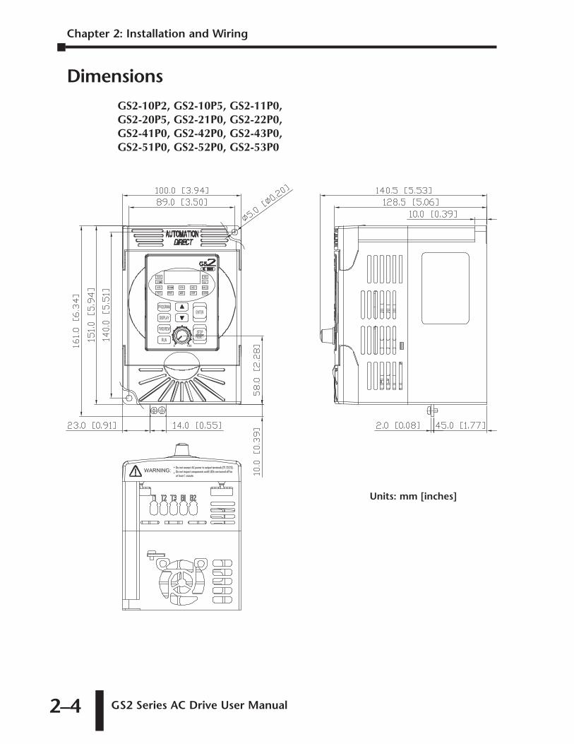
DimensionsGS2-10P2, GS2-10P5, GS2-11P0,GS2-20P5, GS2-21P0, GS2-22P0,GS2-41P0, GS2-42P0, GS2-43P0,GS2-51P0, GS2-52P0, GS2-53P0
Units: mm [inches]
GS2 Series AC Drive User Manual 2–5
Chapter 2: Installation and Wiring
1st Ed. Rev. C 12/2006
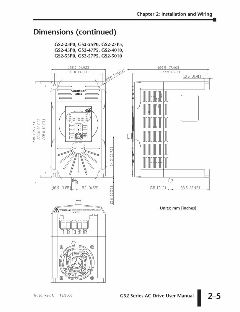
Dimensions (continued)GS2-23P0, GS2-25P0, GS2-27P5,GS2-45P0, GS2-47P5, GS2-4010,GS2-55P0, GS2-57P5, GS2-5010
Units: mm [inches]
Chapter 2: Installation and Wiring
GS2 Series AC Drive User Manual2–6
GS2 Circuit Connections
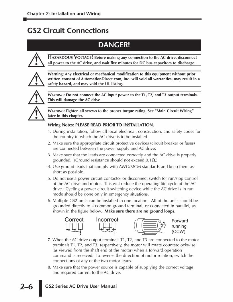
DANGER!
HAZARDOUS VOLTAGE! Before making any connection to the AC drive, disconnectall power to the AC drive, and wait five minutes for DC bus capacitors to discharge.
Warning: Any electrical or mechanical modification to this equipment without priorwritten consent of AutomationDirect.com, Inc. will void all warranties, may result in asafety hazard, and may void the UL listing.
WARNING: Do not connect the AC input power to the T1, T2, and T3 output terminals.This will damage the AC drive
WARNING: Tighten all screws to the proper torque rating. See “Main Circuit Wiring”later in this chapter.
Wiring Notes: PLEASE READ PRIOR TO INSTALLATION.
1. During installation, follow all local electrical, construction, and safety codes forthe country in which the AC drive is to be installed.
2. Make sure the appropriate circuit protective devices (circuit breaker or fuses)are connected between the power supply and AC drive.
3. Make sure that the leads are connected correctly and the AC drive is properlygrounded. (Ground resistance should not exceed 0.1�.)
4. Use ground leads that comply with AWG/MCM standards and keep them asshort as possible.
5. Do not use a power circuit contactor or disconnect switch for run/stop controlof the AC drive and motor. This will reduce the operating life cycle of the ACdrive. Cycling a power circuit switching device while the AC drive is in runmode should be done only in emergency situations.
6. Multiple GS2 units can be installed in one location. All of the units should begrounded directly to a common ground terminal, or connected in parallel, asshown in the figure below. Make sure there are no ground loops.
7. When the AC drive output terminals T1, T2, and T3 are connected to the motorterminals T1, T2, and T3, respectively, the motor will rotate counterclockwise(as viewed from the shaft end of the motor) when a forward operationcommand is received. To reverse the direction of motor rotation, switch theconnections of any of the two motor leads.
8. Make sure that the power source is capable of supplying the correct voltageand required current to the AC drive.
Correct Incorrect Forwardrunning(CCW)
GS2 Series AC Drive User Manual 2–7
Chapter 2: Installation and Wiring
1st Ed. Rev. C 12/2006
9. Do not attach or remove wiring when power is applied to the AC drive.
10. Do not inspect components unless inside "POWER" lamp is turned off.
11. Do not monitor the signals on the circuit board while the AC drive is in operation.
12. For the 115V single-phase rated AC drives, AC power must be connected toinput terminals L1 and L2. For the 230V single-phase rated AC drives, ACpower can be connected to any two of the three input terminals L1, L2, andL3. Note: This AC drive is not intended for use with single-phase motors.
13. Route the power and control wires separately, or at 90 degree angle to each other.
14. If a filter is required for reducing EMI (Electro-Magnetic Interference), install it as closeas possible to the AC drive. EMI can also be reduced by lowering the Carrier Frequency.
15. If the AC drive is installed in a place where a load reactor is needed, installthe filter close to the T1, T2, and T3 side of AC drive. Do not use a Capacitor,L-C Filter (Inductance-Capacitance), or R-C Filter (Resistance-Capacitance),unless approved by AutomationDirect.
16. When using a GFCI (Ground Fault Circuit Interrupt), select current sensor with sensitivityof 200 mA, and not less than 0.1-second detection to avoid nuisance tripping.
Motor Operation Precautions
1. If the AC drive is used to operate a standard 3-phase induction motor, theenergy loss is greater than if using an inverter duty motor.
2. Avoid running a standard induction motor at low speed, which may cause themotor temperature to exceed the motor rating due to limited airflow producedby the motor's fan.
3. When the standard motor operates at low speed, the output load must be decreased.
4. If 100% output torque is desired at low speed, it may be necessary to use aspecial "inverter-duty" rated motor.
Short Circuit Withstand Current
Suitable for use on a circuit capable of delivering not more than 5,000 rmssymmetrical Amperes. The maximum voltage is 120, 240, 480, and 600V for all115, 230, 460, and 575V models, respectively. (An optional line reactor can beinstalled in the incoming power circuit to reduce the available short circuitcurrent.)
Applicable Codes
All GS2 Series AC drives are Underwriters Laboratories, Inc. (UL) and CanadianUnderwriters Laboratories (cUL) listed, and therefore comply with therequirements of the National Electrical Code (NEC) and the Canadian ElectricalCode (CEC).
Installation intended to meet the UL and cUL requirements must follow theinstructions provided in "Wiring Notes" as a minimum standard. Follow all localcodes that exceed UL and cUL requirements. Refer to the technical data labelaffixed to the AC drive and the motor nameplate for electrical data.
The "Fuses and Fuse Kits" section in APPENDIX A, lists the recommended fuse partnumber for each GS2 Series part number. These fuses (or equivalent) must beused on all installations where compliance with U.L. standards is required.
Chapter 2: Installation and Wiring
GS2 Series AC Drive User Manual2–8
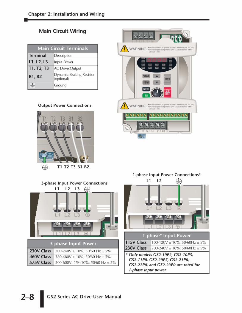
Main Circuit Wiring
3-phase Input Power Connections
1-phase Input Power Connections*
Output Power Connections
T1 T2 T3 B1 B2
L1 L2 L3
L1 L2
Main Circuit TerminalsTerminal Description
L1, L2, L3 Input Power
T1, T2, T3 AC Drive Output
B1, B2 Dynamic Braking Resistor(optional)
Ground
3-phase Input Power
230V Class 200-240V ± 10%; 50/60 Hz ± 5%
460V Class 380-480V ± 10%; 50/60 Hz ± 5%
575V Class 500-600V -15/+10%; 50/60 Hz ± 5%
1-phase* Input Power115V Class 100-120V ± 10%; 50/60Hz ± 5%
230V Class 200-240V ± 10%; 50/60Hz ± 5%
* Only models GS2-10P2, GS2-10P5,GS2-11P0, GS2-20P5, GS2-21P0,GS2-22P0, and GS2-23P0 are rated for 1-phase input power
GS2 Series AC Drive User Manual 2–9
Main Circuit Wiring (continued)
Chapter 2: Installation and Wiring
1st Ed. Rev. C 12/2006
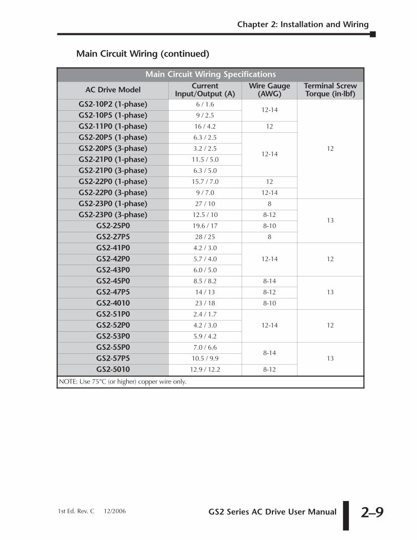
Main Circuit Wiring Specifications
AC Drive Model CurrentInput/Output (A)
Wire Gauge(AWG)
Terminal ScrewTorque (in·lbf)
GS2-10P2 (1-phase) 6 / 1.612-14
12
GS2-10P5 (1-phase) 9 / 2.5
GS2-11P0 (1-phase) 16 / 4.2 12
GS2-20P5 (1-phase) 6.3 / 2.5
12-14GS2-20P5 (3-phase) 3.2 / 2.5
GS2-21P0 (1-phase) 11.5 / 5.0
GS2-21P0 (3-phase) 6.3 / 5.0
GS2-22P0 (1-phase) 15.7 / 7.0 12
GS2-22P0 (3-phase) 9 / 7.0 12-14
GS2-23P0 (1-phase) 27 / 10 8
13GS2-23P0 (3-phase) 12.5 / 10 8-12
GS2-25P0 19.6 / 17 8-10
GS2-27P5 28 / 25 8
GS2-41P0 4.2 / 3.0
12-14 12GS2-42P0 5.7 / 4.0
GS2-43P0 6.0 / 5.0
GS2-45P0 8.5 / 8.2 8-14
13GS2-47P5 14 / 13 8-12
GS2-4010 23 / 18 8-10
GS2-51P0 2.4 / 1.7
12-14 12GS2-52P0 4.2 / 3.0
GS2-53P0 5.9 / 4.2
GS2-55P0 7.0 / 6.68-14
13GS2-57P5 10.5 / 9.9
GS2-5010 12.9 / 12.2 8-12
NOTE: Use 75°C (or higher) copper wire only.
Chapter 2: Installation and Wiring
GS2 Series AC Drive User Manual2–10
Control Terminal Wiring
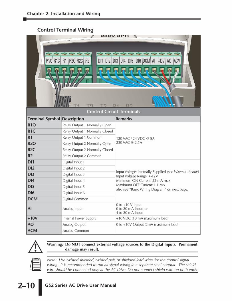
Control Circuit Terminals
Terminal Symbol Description RemarksR1O Relay Output 1 Normally Open
120 VAC / 24 VDC @ 5A230 VAC @ 2.5A
R1C Relay Output 1 Normally Closed
R1 Relay Output 1 Common
R2O Relay Output 2 Normally Open
R2C Relay Output 2 Normally Closed
R2 Relay Output 2 Common
DI1 Digital Input 1
Input Voltage: Internally Supplied (see WARNING below)Input Voltage Range: 4-12VMinimum ON Current: 22 mA maxMaximum OFF Current: 1.1 mAalso see “Basic Wiring Diagram” on next page.
DI2 Digital Input 2
DI3 Digital Input 3
DI4 Digital Input 4
DI5 Digital Input 5
DI6 Digital Input 6
DCM Digital Common
AI Analog Input0 to +10 V Input 0 to 20 mA Input, or4 to 20 mA Input
+10V Internal Power Supply +10 VDC (10 mA maximum load)
AO Analog Output 0 to +10V Output (2mA maximum load)
ACM Analog Common
Note: Use twisted-shielded, twisted-pair, or shielded-lead wires for the control signalwiring. It is recommended to run all signal wiring in a separate steel conduit. The shieldwire should be connected only at the AC drive. Do not connect shield wire on both ends.
Warning: Do NOT connect external voltage sources to the Digital Inputs. Permanentdamage may result.
GS2 Series AC Drive User Manual 2–11
Chapter 2: Installation and Wiring
1st Ed. Rev. C 12/2006
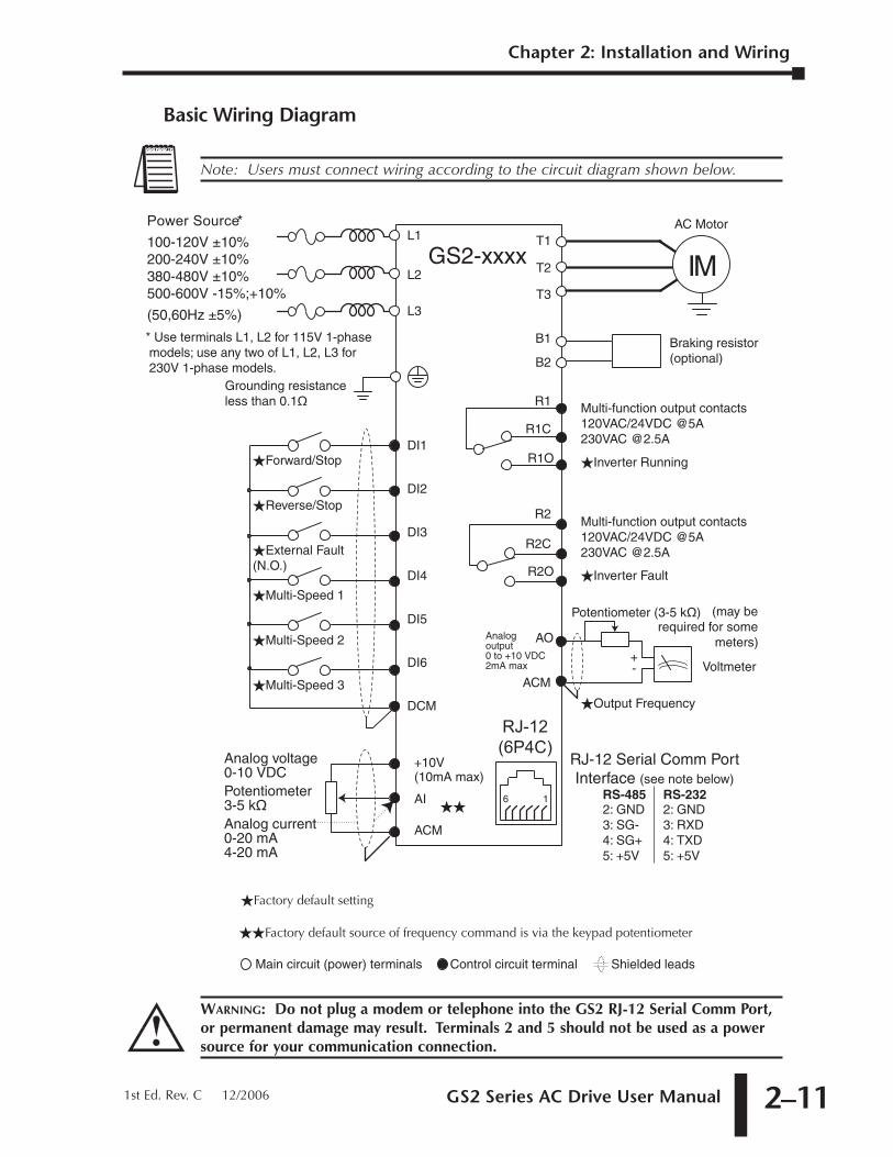
Basic Wiring Diagram
Control circuit terminal Shielded leadsMain circuit (power) terminals
P o w e r S o u r c e*100-120V ±10%200-240V ±10%380-480V ±10%500-600V -15%;+10%
(50,60Hz ±5%)
IMGS2-xxxx
AC Motor
Grounding resistance less than 0.1�
Braking resistor(optional)
B1
B2
T3
T1
T2
�Forward/Stop
�Reverse/Stop
�External Fault(N.O.)
�Multi-Speed 1
�Multi-Speed 2
�Multi-Speed 3
DI1
DI2
DI3
DI4
DI5
DCM
DI6
+10V(10mA max)
AI
ACM
Potentiometer3-5 k�
Analog voltage0-10 VDC
Analog current0-20 mA4-20 mA
* Use terminals L1, L2 for 115V 1-phase models; use any two of L1, L2, L3 for 230V 1-phase models.
R1C
R1
R1O �Inverter Running
Multi-function output contacts120VAC/24VDC @5A230VAC @2.5A
R2
R2C
R2O �Inverter Fault
Multi-function output contacts120VAC/24VDC @5A230VAC @2.5A
L1
L3
L2
16
RJ-12 Serial Comm PortInterface (see note below)
RS-4852: GND3: SG-4: SG+5: +5V
2: GND3: RXD4: TXD5: +5V
RS-232
+-
AO
ACM
Potentiometer (3-5 k�)
Analogoutput0 to +10 VDC2mA max
�Output Frequency
Voltmeter
(may berequired for some
meters)
RJ-12(6P4C)
��Factory default source of frequency command is via the keypad potentiometer
�Factory default setting
��
WARNING: Do not plug a modem or telephone into the GS2 RJ-12 Serial Comm Port,or permanent damage may result. Terminals 2 and 5 should not be used as a powersource for your communication connection.
Note: Users must connect wiring according to the circuit diagram shown below.
Chapter 2: Installation and Wiring
GS2 Series AC Drive User Manual2–12
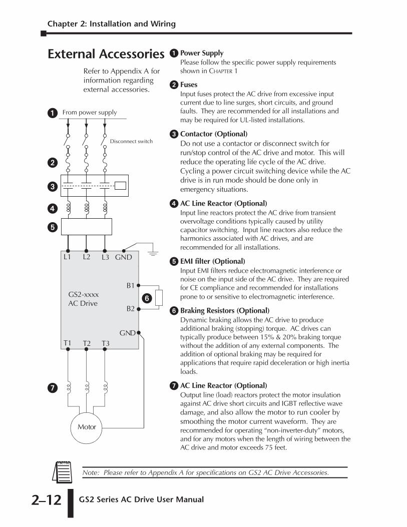
External AccessoriesRefer to Appendix A forinformation regardingexternal accessories.
Motor
L1 L3L2
T1 T3T2GND
B1
B2
From power supply
GS2-xxxxAC Drive
GND
Disconnect switch
� Power SupplyPlease follow the specific power supply requirementsshown in CHAPTER 1
� FusesInput fuses protect the AC drive from excessive inputcurrent due to line surges, short circuits, and groundfaults. They are recommended for all installations andmay be required for UL-listed installations.
� Contactor (Optional)Do not use a contactor or disconnect switch forrun/stop control of the AC drive and motor. This willreduce the operating life cycle of the AC drive.Cycling a power circuit switching device while the ACdrive is in run mode should be done only inemergency situations.
� AC Line Reactor (Optional)Input line reactors protect the AC drive from transientovervoltage conditions typically caused by utilitycapacitor switching. Input line reactors also reduce theharmonics associated with AC drives, and arerecommended for all installations.
� EMI filter (Optional)Input EMI filters reduce electromagnetic interference ornoise on the input side of the AC drive. They are requiredfor CE compliance and recommended for installationsprone to or sensitive to electromagnetic interference.
� Braking Resistors (Optional)Dynamic braking allows the AC drive to produceadditional braking (stopping) torque. AC drives cantypically produce between 15% & 20% braking torquewithout the addition of any external components. Theaddition of optional braking may be required forapplications that require rapid deceleration or high inertialoads.
� AC Line Reactor (Optional)Output line (load) reactors protect the motor insulationagainst AC drive short circuits and IGBT reflective wavedamage, and also allow the motor to run cooler bysmoothing the motor current waveform. They arerecommended for operating “non-inverter-duty” motors,and for any motors when the length of wiring between theAC drive and motor exceeds 75 feet.
�
�
�
�
�
�
�
Note: Please refer to Appendix A for specifications on GS2 AC Drive Accessories.
KEYPAD OPERATION
AND QUICKSTART 3CHAPTERCHAPTER
33CHAPTER
In This Chapter...
The GS2 Digital Keypad . . . . . . . . . . . . . . . . . . . . .3–2LED Display . . . . . . . . . . . . . . . . . . . . . . . . . . . . . . . . . . . . . . . . .3–2
LED Indicators . . . . . . . . . . . . . . . . . . . . . . . . . . . . . . . . . . . . . . .3–2
Function Keys . . . . . . . . . . . . . . . . . . . . . . . . . . . . . . . . . . . . . . .3–3
Displaying the Status of the GS2 AC Drive . . . . . . . . . . . . . . . . .3–4
Programming the GS2 AC Drive . . . . . . . . . . . . . . . . . . . . . . . . .3–5
GS2 Quickstart . . . . . . . . . . . . . . . . . . . . . . . . . . . .3–6Example 1: Constant torque (e.g. conveyors, compressors, etc.) .3–6
Example 2: Variable torque (e.g. fans, centrifugal pumps, etc.) .3–11
Chapter 3: Keypad Operation and Quickstart
GS2 Series AC Drive User Manual3–2
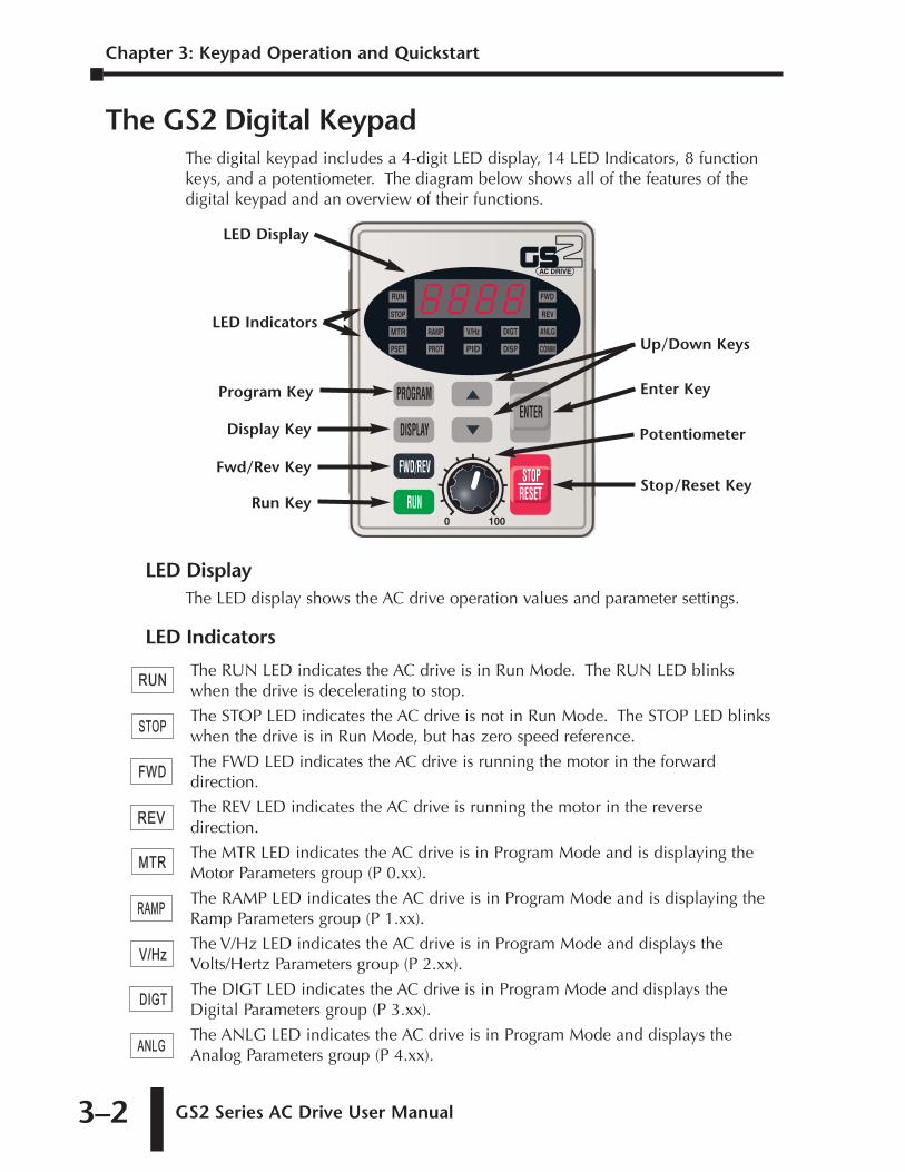
The GS2 Digital KeypadThe digital keypad includes a 4-digit LED display, 14 LED Indicators, 8 functionkeys, and a potentiometer. The diagram below shows all of the features of thedigital keypad and an overview of their functions.
LED DisplayThe LED display shows the AC drive operation values and parameter settings.
LED Indicators
The RUN LED indicates the AC drive is in Run Mode. The RUN LED blinkswhen the drive is decelerating to stop.
The STOP LED indicates the AC drive is not in Run Mode. The STOP LED blinkswhen the drive is in Run Mode, but has zero speed reference.
The FWD LED indicates the AC drive is running the motor in the forwarddirection.
The REV LED indicates the AC drive is running the motor in the reversedirection.
The MTR LED indicates the AC drive is in Program Mode and is displaying theMotor Parameters group (P 0.xx).
The RAMP LED indicates the AC drive is in Program Mode and is displaying theRamp Parameters group (P 1.xx).
The V/Hz LED indicates the AC drive is in Program Mode and displays theVolts/Hertz Parameters group (P 2.xx).
The DIGT LED indicates the AC drive is in Program Mode and displays theDigital Parameters group (P 3.xx).
The ANLG LED indicates the AC drive is in Program Mode and displays theAnalog Parameters group (P 4.xx).
RUNRUN
STOP
MTR
PSET
RAMP
PROT PID
V/Hz DIGT
DISP
FWD
REV
ANLG
COMM
RUN
STOPSTOP
MTR
PSET
RAMP
PROT PID
V/Hz DIGT
DISP
FWD
REV
ANLG
COMM
RUN
STOP
MTR
PSET
RAMP
PROT PID
V/Hz DIGT
DISP
FWFWD
REV
ANLG
COMM
RUN
STOP
MTR
PSET
RAMP
PROT PID
V/Hz DIGT
DISP
FWD
REVREV
ANLG
COMM
RUN
STOP
MTRMTR
PSET
RAMP
PROT PID
V/Hz DIGT
DISP
FWD
REV
ANLG
COMM
RUN
STOP
MTR
PSET
RAMPRAMP
PROT PID
V/Hz DIGT
DISP
FWD
REV
ANLG
COMM
RUN
STOP
MTR
PSET
RAMP
PROT PID
V/HzV/Hz DIGT
DISP
FWD
REV
ANLG
COMM
RUN
STOP
MTR
PSET
RAMP
PROT PID
V/Hz DIGTDIGT
DISP
FWD
REV
ANLG
COMM
RUN
STOP
MTR
PSET
RAMP
PROT PID
V/Hz DIGT
DISP
FWD
REV
ANLGANLG
COMM
Program Key
LED Indicators
LED Display
Up/Down Keys
Enter Key
Stop/Reset Key
PotentiometerDisplay Key
Fwd/Rev Key
Run Key
GS2 Series AC Drive User Manual 3–3
Function Keys
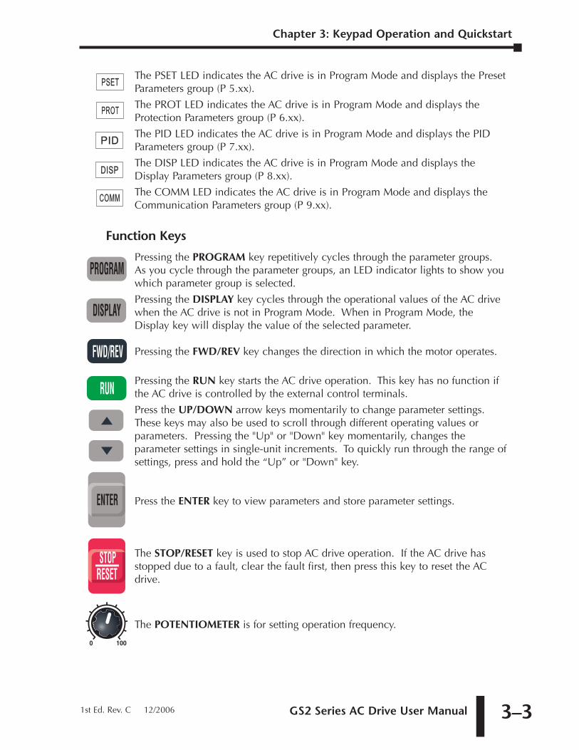
Pressing the PROGRAM key repetitively cycles through the parameter groups.As you cycle through the parameter groups, an LED indicator lights to show youwhich parameter group is selected.
Pressing the DISPLAY key cycles through the operational values of the AC drivewhen the AC drive is not in Program Mode. When in Program Mode, theDisplay key will display the value of the selected parameter.
Pressing the FWD/REV key changes the direction in which the motor operates.
Pressing the RUN key starts the AC drive operation. This key has no function ifthe AC drive is controlled by the external control terminals.
Press the UP/DOWN arrow keys momentarily to change parameter settings.These keys may also be used to scroll through different operating values orparameters. Pressing the "Up" or "Down" key momentarily, changes theparameter settings in single-unit increments. To quickly run through the range ofsettings, press and hold the “Up” or "Down" key.
Press the ENTER key to view parameters and store parameter settings.
The STOP/RESET key is used to stop AC drive operation. If the AC drive hasstopped due to a fault, clear the fault first, then press this key to reset the ACdrive.
The POTENTIOMETER is for setting operation frequency.
The PSET LED indicates the AC drive is in Program Mode and displays the PresetParameters group (P 5.xx).
The PROT LED indicates the AC drive is in Program Mode and displays theProtection Parameters group (P 6.xx).
The PID LED indicates the AC drive is in Program Mode and displays the PIDParameters group (P 7.xx).
The DISP LED indicates the AC drive is in Program Mode and displays theDisplay Parameters group (P 8.xx).
The COMM LED indicates the AC drive is in Program Mode and displays theCommunication Parameters group (P 9.xx).
RUN
STOP
MTR
PSETPSET
RAMP
PROT PID
V/Hz DIGT
DISP
FWD
REV
ANLG
COMM
RUN
STOP
MTR
PSET
RAMP
PROTPROT PID
V/Hz DIGT
DISP
FWD
REV
ANLG
COMM
RUN
STOP
MTR
PSET
RAMP
PROT PIDPID
V/Hz DIGT
DISP
FWD
REV
ANLG
COMM
RUN
STOP
MTR
PSET
RAMP
PROT PID
V/Hz DIGT
DISPDISP
FWD
REV
ANLG
COMM
RUN
STOP
MTR
PSET
RAMP
PROT PID
V/Hz DIGT
DISP
FWD
REV
ANLG
COMMCOMM
Chapter 3: Keypad Operation and Quickstart
1st Ed. Rev. C 12/2006
Chapter 3: Keypad Operation and Quickstart
GS2 Series AC Drive User Manual3–4
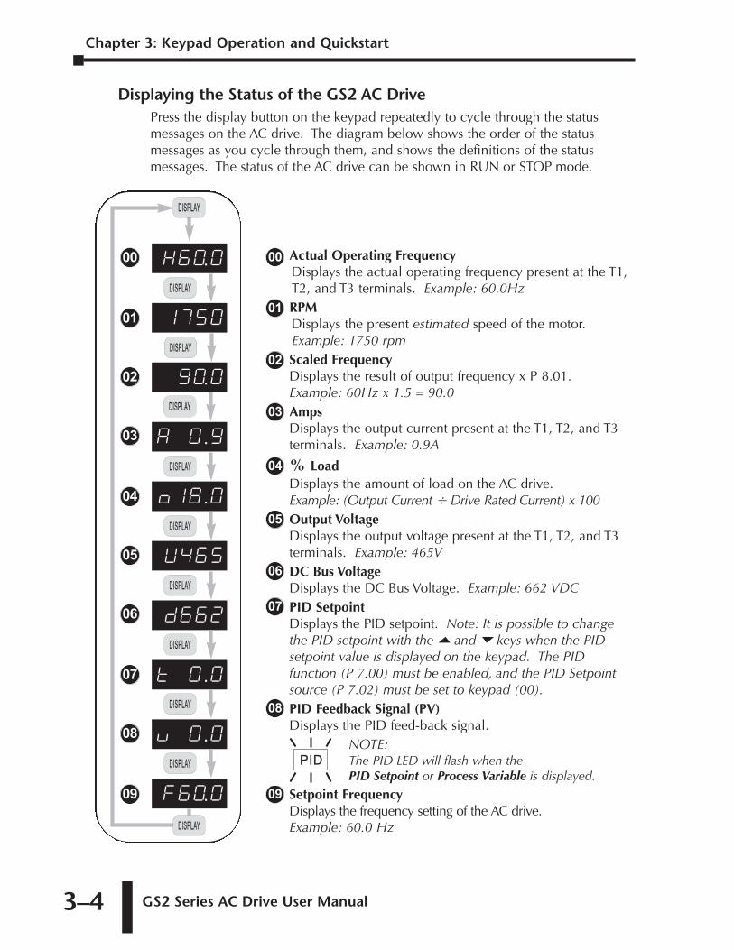
Displaying the Status of the GS2 AC DrivePress the display button on the keypad repeatedly to cycle through the statusmessages on the AC drive. The diagram below shows the order of the statusmessages as you cycle through them, and shows the definitions of the statusmessages. The status of the AC drive can be shown in RUN or STOP mode.
Actual Operating FrequencyDisplays the actual operating frequency present at the T1,T2, and T3 terminals. Example: 60.0HzRPMDisplays the present estimated speed of the motor. Example: 1750 rpmScaled FrequencyDisplays the result of output frequency x P 8.01. Example: 60Hz x 1.5 = 90.0AmpsDisplays the output current present at the T1, T2, and T3terminals. Example: 0.9A
% LoadDisplays the amount of load on the AC drive. Example: (Output Current � Drive Rated Current) x 100Output VoltageDisplays the output voltage present at the T1, T2, and T3terminals. Example: 465VDC Bus VoltageDisplays the DC Bus Voltage. Example: 662 VDCPID SetpointDisplays the PID setpoint. Note: It is possible to changethe PID setpoint with the � and � keys when the PIDsetpoint value is displayed on the keypad. The PIDfunction (P 7.00) must be enabled, and the PID Setpointsource (P 7.02) must be set to keypad (00).PID Feedback Signal (PV)Displays the PID feed-back signal.
NOTE:The PID LED will flash when the PID Setpoint or Process Variable is displayed.
Setpoint FrequencyDisplays the frequency setting of the AC drive.Example: 60.0 Hz
00
01
02
03
07
04
05
06
08
09
RUN
STOP
MTR
PSET
RAMP
PROT PIDPID
V/Hz DIGT
DISP
FWD
REV
ANLG
COMM
U465
d662
t 0.0
F60.0
X60.0
!750
90.0
A 0.9
o!8.0
0 100
PROGRAM
DISPLAYDISPLAY
FWD/REV
RUN
STOP
RESET
ENTER
0 100
PROGRAM
DISPLAYDISPLAY
FWD/REV
RUN
STOP
RESET
ENTER
0 100
PROGRAM
DISPLAYDISPLAY
FWD/REV
RUN
STOP
RESET
ENTER
00
01
02
03
04
05
06
07
09
u 0.008
0 100
PROGRAM
DISPLAYDISPLAY
FWD/REV
RUN
STOP
RESET
ENTER
0 100
PROGRAM
DISPLAYDISPLAY
FWD/REV
RUN
STOP
RESET
ENTER
0 100
PROGRAM
DISPLAYDISPLAY
FWD/REV
RUN
STOP
RESET
ENTER
0 100
PROGRAM
DISPLAYDISPLAY
FWD/REV
RUN
STOP
RESET
ENTER
0 100
PROGRAM
DISPLAYDISPLAY
FWD/REV
RUN
STOP
RESET
ENTER
0 100
PROGRAM
DISPLAYDISPLAY
FWD/REV
RUN
STOP
RESET
ENTER
0 100
PROGRAM
DISPLAYDISPLAY
FWD/REV
RUN
STOP
RESET
ENTER
0 100
PROGRAM
DISPLAYDISPLAY
FWD/REV
RUN
STOP
RESET
ENTER
GS2 Series AC Drive User Manual 3–5
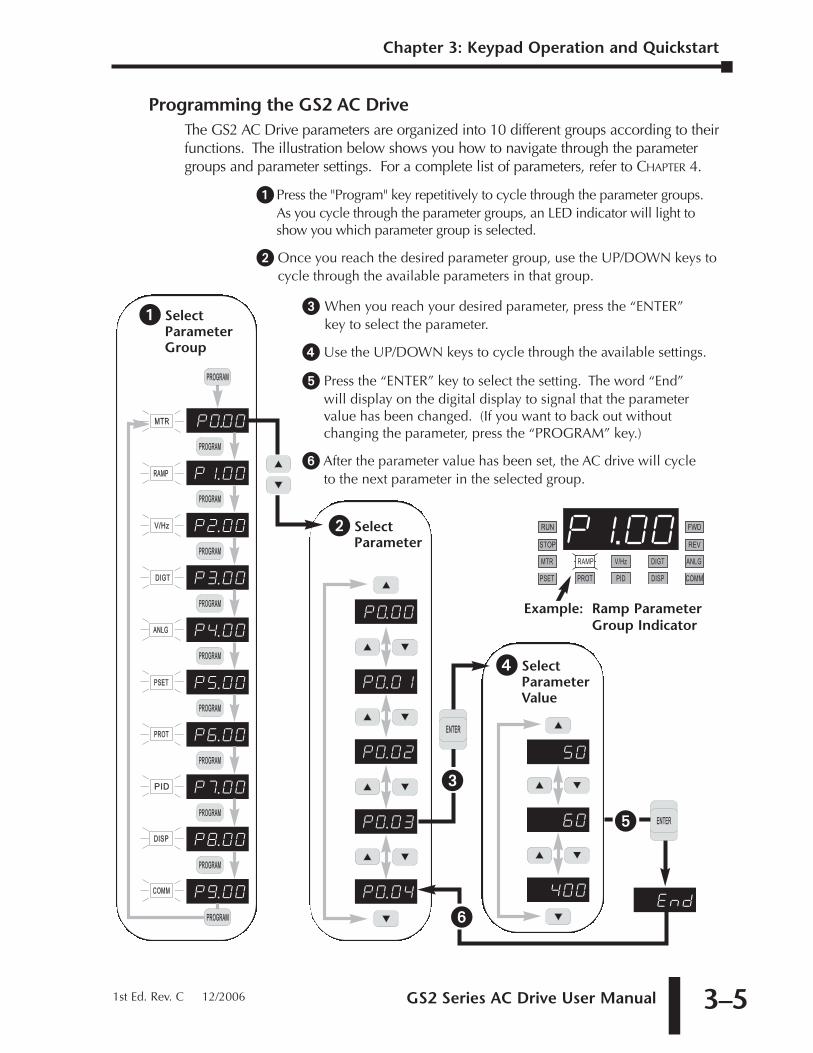
Programming the GS2 AC DriveThe GS2 AC Drive parameters are organized into 10 different groups according to theirfunctions. The illustration below shows you how to navigate through the parametergroups and parameter settings. For a complete list of parameters, refer to CHAPTER 4.
� Press the "Program" key repetitively to cycle through the parameter groups.As you cycle through the parameter groups, an LED indicator will light toshow you which parameter group is selected.
� Once you reach the desired parameter group, use the UP/DOWN keys tocycle through the available parameters in that group.
RUN
STOP
MTR
PSET
RAMP
PROT PID
V/Hz DIGT
DISP
FWD
REV
ANLG
COMM
P!.00
P0.00
P0.0!
P0.02
P0.03
P0.04
0 100
PROGRAM
DISPLAY
FWD/REV
RUN
STOP
RESET
ENTER
0 100
PROGRAM
DISPLAY
FWD/REV
RUN
STOP
RESET
ENTER
0 100
PROGRAM
DISPLAY
FWD/REV
RUN
STOP
RESET
ENTER
0 100
PROGRAM
DISPLAY
FWD/REV
RUN
STOP
RESET
ENTER
0 100
PROGRAM
DISPLAY
FWD/REV
RUN
STOP
RESET
ENTER
0 100
PROGRAM
DISPLAY
FWD/REV
RUN
STOP
RESET
ENTER
0 100
PROGRAM
DISPLAY
FWD/REV
RUN
STOP
RESET
ENTER
0 100
PROGRAM
DISPLAY
FWD/REV
RUN
STOP
RESET
ENTER
0 100
PROGRAM
DISPLAY
FWD/REV
RUN
STOP
RESET
ENTER
0 100
PROGRAM
DISPLAY
FWD/REV
RUN
STOP
RESET
ENTER
50
60
End400
0 100
PROGRAM
DISPLAY
FWD/REV
RUN
STOP
RESET
ENTER
0 100
PROGRAM
DISPLAY
FWD/REV
RUN
STOP
RESET
ENTER
0 100
PROGRAM
DISPLAY
FWD/REV
RUN
STOP
RESET
ENTER
0 100
PROGRAM
DISPLAY
FWD/REV
RUN
STOP
RESET
ENTER
0 100
PROGRAM
DISPLAY
FWD/REV
RUN
STOP
RESET
ENTER
0 100
PROGRAM
DISPLAY
FWD/REV
RUN
STOP
RESET
ENTER
� When you reach your desired parameter, press the “ENTER”key to select the parameter.
� Use the UP/DOWN keys to cycle through the available settings.
� Press the “ENTER” key to select the setting. The word “End”will display on the digital display to signal that the parametervalue has been changed. (If you want to back out withoutchanging the parameter, press the “PROGRAM” key.)
� After the parameter value has been set, the AC drive will cycleto the next parameter in the selected group.
� SelectParameterGroup
� SelectParameter
� SelectParameterValue
0 100
PROGRAM
DISPLAY
FWD/REV
RUN
STOP
RESET
ENTERENTER
0 100
PROGRAM
DISPLAY
FWD/REV
RUN
STOP
RESET
ENTERENTER
�
�
�
0 100
PROGRAM
DISPLAY
FWD/REV
RUN
STOP
RESET
ENTER
P9.00
P5.00
P6.00
P7.00
P8.00
P0.00
P!.00
P2.00
P3.00
P4.00
0 100
PROGRAMPROGRAM
DISPLAY
FWD/REV
RUN
STOP
RESET
ENTER
0 100
PROGRAMPROGRAM
DISPLAY
FWD/REV
RUN
STOP
RESET
ENTER
0 100
PROGRAMPROGRAM
DISPLAY
FWD/REV
RUN
STOP
RESET
ENTER
0 100
PROGRAMPROGRAM
DISPLAY
FWD/REV
RUN
STOP
RESET
ENTER
0 100
PROGRAMPROGRAM
DISPLAY
FWD/REV
RUN
STOP
RESET
ENTER
0 100
PROGRAMPROGRAM
DISPLAY
FWD/REV
RUN
STOP
RESET
ENTER
0 100
PROGRAMPROGRAM
DISPLAY
FWD/REV
RUN
STOP
RESET
ENTER
0 100
PROGRAMPROGRAM
DISPLAY
FWD/REV
RUN
STOP
RESET
ENTER
0 100
PROGRAMPROGRAM
DISPLAY
FWD/REV
RUN
STOP
RESET
ENTER
0 100
PROGRAMPROGRAM
DISPLAY
FWD/REV
RUN
STOP
RESET
ENTER
0 100
PROGRAMPROGRAM
DISPLAY
FWD/REV
RUN
STOP
RESET
ENTER
RUN
STOP
MTR
PSET
RAMPRAMP
PROT PID
V/Hz DIGT
DISP
FWD
REV
ANLG
COMM
RUN
STOP
MTR
PSET
RAMP
PROT PID
V/HzV/Hz DIGT
DISP
FWD
REV
ANLG
COMM
RUN
STOP
MTR
PSET
RAMP
PROT PID
V/Hz DIGTDIGT
DISP
FWD
REV
ANLG
COMM
RUN
STOP
MTR
PSET
RAMP
PROT PID
V/Hz DIGT
DISP
FWD
REV
ANLGANLG
COMM
RUN
STOP
MTR
PSETPSET
RAMP
PROT PID
V/Hz DIGT
DISP
FWD
REV
ANLG
COMM
RUN
STOP
MTR
PSET
RAMP
PROTPROT PID
V/Hz DIGT
DISP
FWD
REV
ANLG
COMM
RUN
STOP
MTR
PSET
RAMP
PROT PIDPID
V/Hz DIGT
DISP
FWD
REV
ANLG
COMM
RUN
STOP
MTR
PSET
RAMP
PROT PID
V/Hz DIGT
DISPDISP
FWD
REV
ANLG
COMM
RUN
STOP
MTR
PSET
RAMP
PROT PID
V/Hz DIGT
DISP
FWD
REV
ANLG
COMMCOMM
RUN
STOP
MTRMTR
PSET
RAMP
PROT PID
V/Hz DIGT
DISP
FWD
REV
ANLG
COMM
Example: Ramp ParameterGroup Indicator
Chapter 3: Keypad Operation and Quickstart
1st Ed. Rev. C 12/2006
Chapter 3: Keypad Operation and Quickstart
GS2 Series AC Drive User Manual3–6
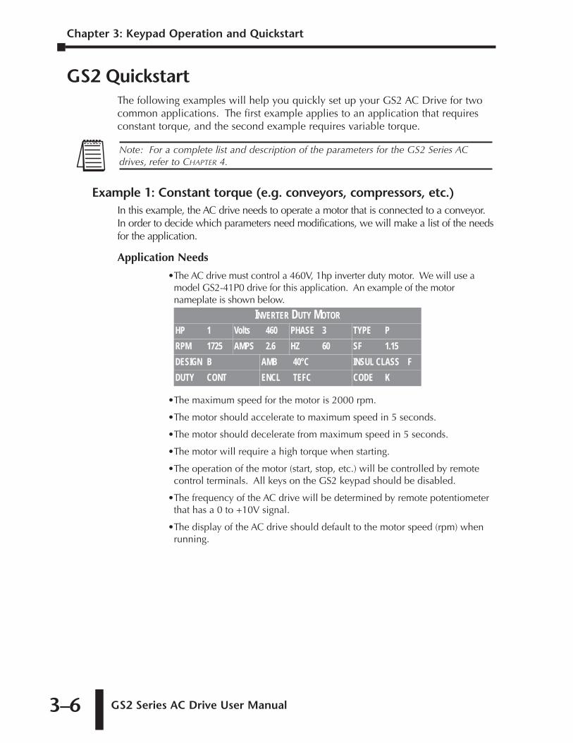
GS2 QuickstartThe following examples will help you quickly set up your GS2 AC Drive for twocommon applications. The first example applies to an application that requiresconstant torque, and the second example requires variable torque.
Example 1: Constant torque (e.g. conveyors, compressors, etc.)In this example, the AC drive needs to operate a motor that is connected to a conveyor.In order to decide which parameters need modifications, we will make a list of the needsfor the application.
Application Needs
•The AC drive must control a 460V, 1hp inverter duty motor. We will use amodel GS2-41P0 drive for this application. An example of the motornameplate is shown below.
•The maximum speed for the motor is 2000 rpm.
•The motor should accelerate to maximum speed in 5 seconds.
•The motor should decelerate from maximum speed in 5 seconds.
•The motor will require a high torque when starting.
•The operation of the motor (start, stop, etc.) will be controlled by remotecontrol terminals. All keys on the GS2 keypad should be disabled.
•The frequency of the AC drive will be determined by remote potentiometerthat has a 0 to +10V signal.
•The display of the AC drive should default to the motor speed (rpm) whenrunning.
INVERTER DUTY MOTORHP 1 Volts 460 PHASE 3 TYPE PRPM 1725 AMPS 2.6 HZ 60 SF 1.15DESIGN B AMB 40°C INSUL CLASS FDUTY CONT ENCL TEFC CODE K
Note: For a complete list and description of the parameters for the GS2 Series ACdrives, refer to CHAPTER 4.
GS2 Series AC Drive User Manual 3–7
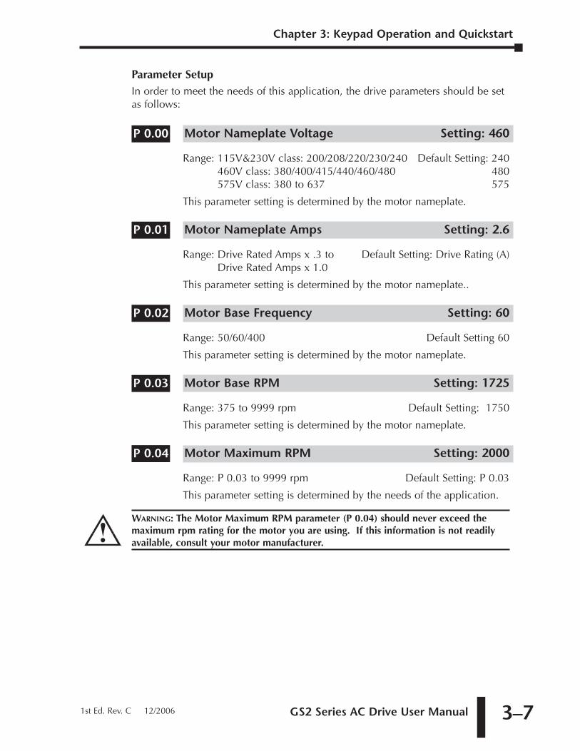
Parameter SetupIn order to meet the needs of this application, the drive parameters should be setas follows:
Motor Nameplate Voltage Setting: 460
Range: 115V&230V class: 200/208/220/230/240 Default Setting: 240460V class: 380/400/415/440/460/480 480575V class: 380 to 637 575
This parameter setting is determined by the motor nameplate.
Motor Nameplate Amps Setting: 2.6
Range: Drive Rated Amps x .3 to Default Setting: Drive Rating (A)Drive Rated Amps x 1.0
This parameter setting is determined by the motor nameplate..
Motor Base Frequency Setting: 60
Range: 50/60/400 Default Setting 60
This parameter setting is determined by the motor nameplate.
Motor Base RPM Setting: 1725
Range: 375 to 9999 rpm Default Setting: 1750
This parameter setting is determined by the motor nameplate.
Motor Maximum RPM Setting: 2000
Range: P 0.03 to 9999 rpm Default Setting: P 0.03
This parameter setting is determined by the needs of the application.
WARNING: The Motor Maximum RPM parameter (P 0.04) should never exceed themaximum rpm rating for the motor you are using. If this information is not readilyavailable, consult your motor manufacturer.
P 0.04
P 0.03
P 0.02
P 0.01
P 0.00
Chapter 3: Keypad Operation and Quickstart
1st Ed. Rev. C 12/2006
Chapter 3: Keypad Operation and Quickstart
GS2 Series AC Drive User Manual3–8
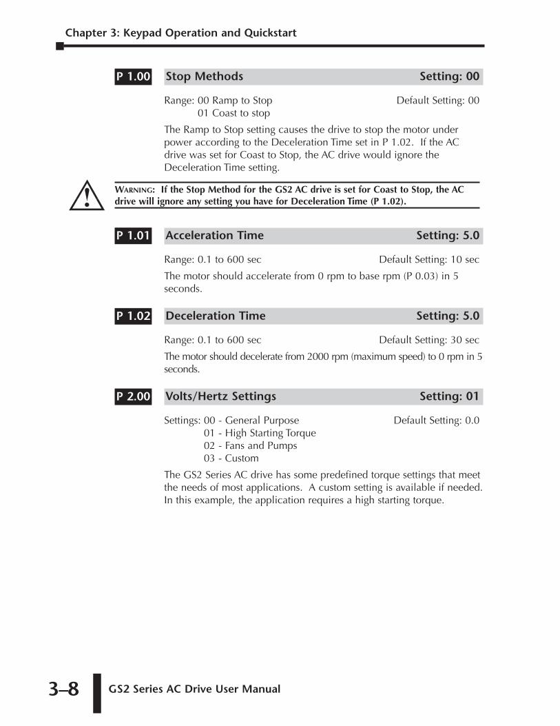
Stop Methods Setting: 00
Range: 00 Ramp to Stop Default Setting: 0001 Coast to stop
The Ramp to Stop setting causes the drive to stop the motor underpower according to the Deceleration Time set in P 1.02. If the ACdrive was set for Coast to Stop, the AC drive would ignore theDeceleration Time setting.
Acceleration Time Setting: 5.0
Range: 0.1 to 600 sec Default Setting: 10 sec
The motor should accelerate from 0 rpm to base rpm (P 0.03) in 5seconds.
Deceleration Time Setting: 5.0
Range: 0.1 to 600 sec Default Setting: 30 sec
The motor should decelerate from 2000 rpm (maximum speed) to 0 rpm in 5seconds.
Volts/Hertz Settings Setting: 01
Settings: 00 - General Purpose Default Setting: 0.001 - High Starting Torque02 - Fans and Pumps03 - Custom
The GS2 Series AC drive has some predefined torque settings that meetthe needs of most applications. A custom setting is available if needed.In this example, the application requires a high starting torque.
P 2.00
P 1.02
P 1.01
WARNING: If the Stop Method for the GS2 AC drive is set for Coast to Stop, the ACdrive will ignore any setting you have for Deceleration Time (P 1.02).
P 1.00
GS2 Series AC Drive User Manual 3–9
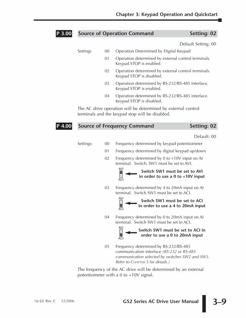
Source of Operation Command Setting: 02
Default Setting: 00
Settings 00 Operation Determined by Digital Keypad
01 Operation determined by external control terminals. Keypad STOP is enabled.
02 Operation determined by external control terminals. Keypad STOP is disabled.
03 Operation determined by RS-232/RS-485 interface. Keypad STOP is enabled.
04 Operation determined by RS-232/RS-485 interface. Keypad STOP is disabled.
The AC drive operation will be determined by external controlterminals and the keypad stop will be disabled.
Source of Frequency Command Setting: 02
Default: 00
Settings: 00 Frequency determined by keypad potentiometer
01 Frequency determined by digital keypad up/down
02 Frequency determined by 0 to +10V input on AIterminal. Switch, SW1 must be set to AVI.
03 Frequency determined by 4 to 20mA input on AIterminal. Switch SW1 must be set to ACI.
04 Frequency determined by 0 to 20mA input on AIterminal. Switch SW1 must be set to ACI.
05 Frequency determined by RS-232/RS-485communication interface (RS-232 or RS-485communication selected by switches SW2 and SW3.Refer to CHAPTER 5 for details.)
The frequency of the AC drive will be determined by an externalpotentiometer with a 0 to +10V signal.
AVI
ACI
Switch SW1 must be set to ACI inorder to use a 0 to 20mA input
AVI
ACI
Switch SW1 must be set to ACI in order to use a 4 to 20mA input
AVI
ACI
Switch SW1 must be set to AVI in order to use a 0 to +10V input
P 4.00
P 3.00
Chapter 3: Keypad Operation and Quickstart
1st Ed. Rev. C 12/2006
Chapter 3: Keypad Operation and Quickstart
GS2 Series AC Drive User Manual3–10
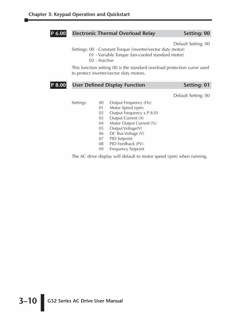
Electronic Thermal Overload Relay Setting: 00
Default Setting: 00Settings: 00 - Constant Torque (inverter/vector duty motor)
01 - Variable Torque (fan-cooled standard motor)02 - Inactive
This function setting 00 is the standard overload protection curve usedto protect inverter/vector duty motors.
User Defined Display Function Setting: 01
Default Setting: 00
Settings: 00 Output Frequency (Hz)01 Motor Speed (rpm)02 Output Frequency x P 8.0103 Output Current (A)04 Motor Output Current (%)05 Output Voltage(V)06 DC Bus Voltage (V)07 PID Setpoint08 PID Feedback (PV)09 Frequency Setpoint
The AC drive display will default to motor speed (rpm) when running.
P 8.00
P 6.00
GS2 Series AC Drive User Manual 3–11
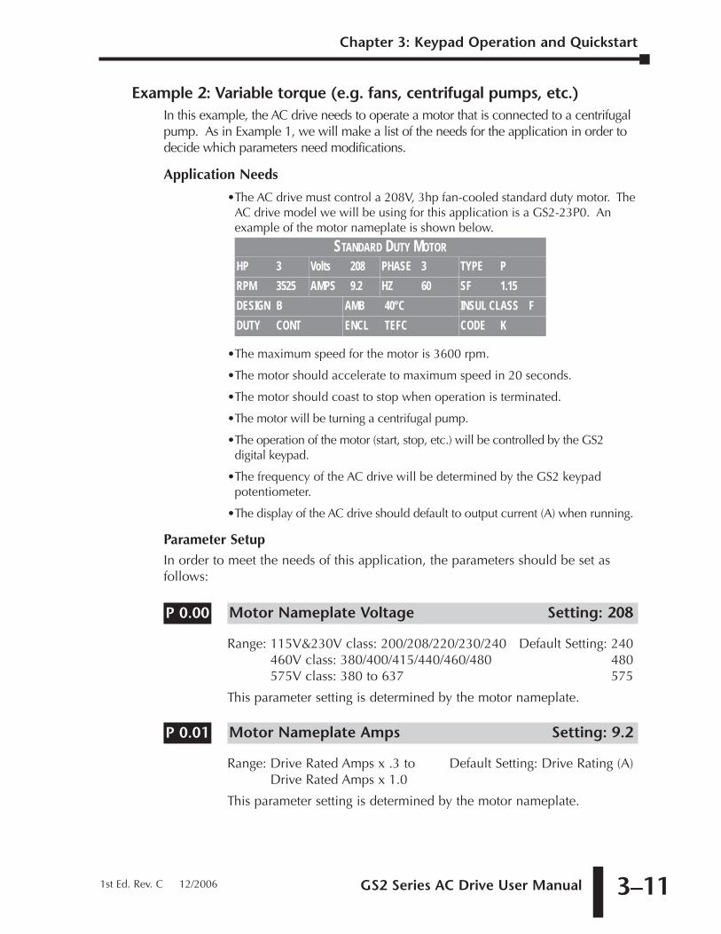
Example 2: Variable torque (e.g. fans, centrifugal pumps, etc.)In this example, the AC drive needs to operate a motor that is connected to a centrifugalpump. As in Example 1, we will make a list of the needs for the application in order todecide which parameters need modifications.
Application Needs
•The AC drive must control a 208V, 3hp fan-cooled standard duty motor. TheAC drive model we will be using for this application is a GS2-23P0. Anexample of the motor nameplate is shown below.
•The maximum speed for the motor is 3600 rpm.
•The motor should accelerate to maximum speed in 20 seconds.
•The motor should coast to stop when operation is terminated.
•The motor will be turning a centrifugal pump.
•The operation of the motor (start, stop, etc.) will be controlled by the GS2digital keypad.
•The frequency of the AC drive will be determined by the GS2 keypadpotentiometer.
•The display of the AC drive should default to output current (A) when running.
Parameter SetupIn order to meet the needs of this application, the parameters should be set asfollows:
Motor Nameplate Voltage Setting: 208
Range: 115V&230V class: 200/208/220/230/240 Default Setting: 240460V class: 380/400/415/440/460/480 480575V class: 380 to 637 575
This parameter setting is determined by the motor nameplate.
Motor Nameplate Amps Setting: 9.2
Range: Drive Rated Amps x .3 to Default Setting: Drive Rating (A)Drive Rated Amps x 1.0
This parameter setting is determined by the motor nameplate.
P 0.01
P 0.00
STANDARD DUTY MOTORHP 3 Volts 208 PHASE 3 TYPE PRPM 3525 AMPS 9.2 HZ 60 SF 1.15DESIGN B AMB 40°C INSUL CLASS FDUTY CONT ENCL TEFC CODE K
Chapter 3: Keypad Operation and Quickstart
1st Ed. Rev. C 12/2006
Chapter 3: Keypad Operation and Quickstart
GS2 Series AC Drive User Manual3–12
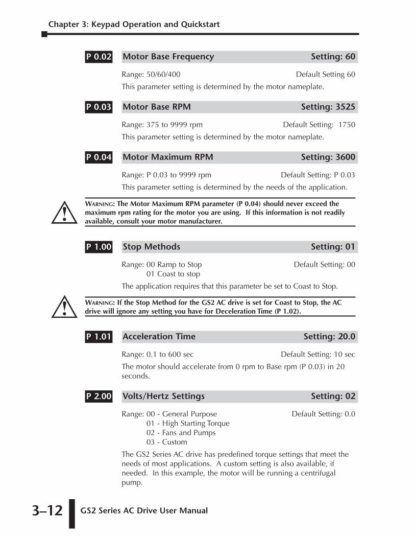
Motor Base Frequency Setting: 60
Range: 50/60/400 Default Setting 60
This parameter setting is determined by the motor nameplate.
Motor Base RPM Setting: 3525
Range: 375 to 9999 rpm Default Setting: 1750
This parameter setting is determined by the motor nameplate.
Motor Maximum RPM Setting: 3600
Range: P 0.03 to 9999 rpm Default Setting: P 0.03
This parameter setting is determined by the needs of the application.
Stop Methods Setting: 01
Range: 00 Ramp to Stop Default Setting: 0001 Coast to stop
The application requires that this parameter be set to Coast to Stop.
Acceleration Time Setting: 20.0
Range: 0.1 to 600 sec Default Setting: 10 sec
The motor should accelerate from 0 rpm to Base rpm (P 0.03) in 20seconds.
Volts/Hertz Settings Setting: 02
Range: 00 - General Purpose Default Setting: 0.001 - High Starting Torque02 - Fans and Pumps03 - Custom
The GS2 Series AC drive has predefined torque settings that meet theneeds of most applications. A custom setting is also available, ifneeded. In this example, the motor will be running a centrifugalpump.
P 2.00
P 1.01
WARNING: If the Stop Method for the GS2 AC drive is set for Coast to Stop, the ACdrive will ignore any setting you have for Deceleration Time (P 1.02).
P 1.00
WARNING: The Motor Maximum RPM parameter (P 0.04) should never exceed themaximum rpm rating for the motor you are using. If this information is not readilyavailable, consult your motor manufacturer.
P 0.04
P 0.03
P 0.02
GS2 Series AC Drive User Manual 3–13
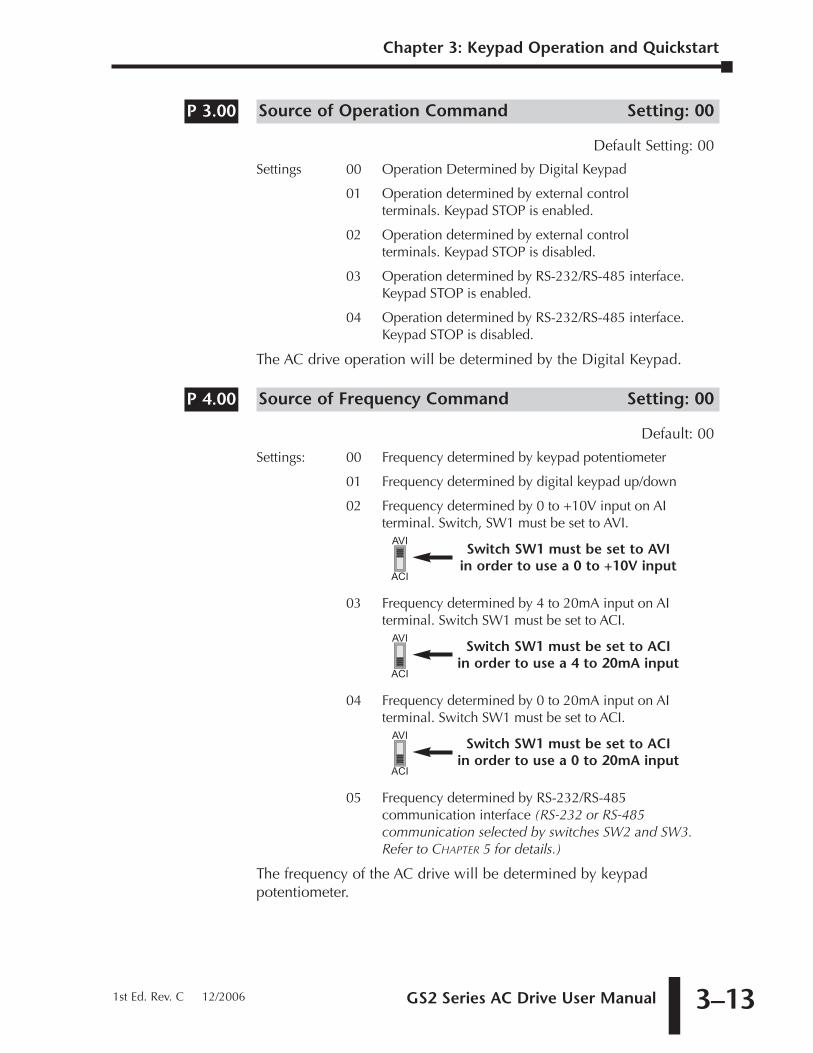
Source of Operation Command Setting: 00
Default Setting: 00
Settings 00 Operation Determined by Digital Keypad
01 Operation determined by external controlterminals. Keypad STOP is enabled.
02 Operation determined by external controlterminals. Keypad STOP is disabled.
03 Operation determined by RS-232/RS-485 interface.Keypad STOP is enabled.
04 Operation determined by RS-232/RS-485 interface.Keypad STOP is disabled.
The AC drive operation will be determined by the Digital Keypad.
Source of Frequency Command Setting: 00
Default: 00
Settings: 00 Frequency determined by keypad potentiometer
01 Frequency determined by digital keypad up/down
02 Frequency determined by 0 to +10V input on AIterminal. Switch, SW1 must be set to AVI.
03 Frequency determined by 4 to 20mA input on AIterminal. Switch SW1 must be set to ACI.
04 Frequency determined by 0 to 20mA input on AIterminal. Switch SW1 must be set to ACI.
05 Frequency determined by RS-232/RS-485communication interface (RS-232 or RS-485communication selected by switches SW2 and SW3.Refer to CHAPTER 5 for details.)
The frequency of the AC drive will be determined by keypadpotentiometer.
AVI
ACI
Switch SW1 must be set to ACI in order to use a 0 to 20mA input
AVI
ACI
Switch SW1 must be set to ACI in order to use a 4 to 20mA input
AVI
ACI
Switch SW1 must be set to AVI in order to use a 0 to +10V input
P 4.00
P 3.00
Chapter 3: Keypad Operation and Quickstart
1st Ed. Rev. C 12/2006
Chapter 3: Keypad Operation and Quickstart
GS2 Series AC Drive User Manual3–14
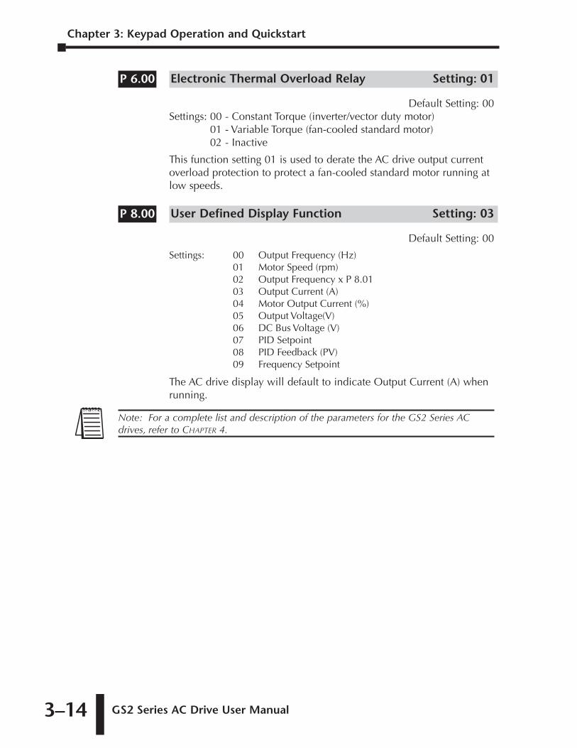
Electronic Thermal Overload Relay Setting: 01
Default Setting: 00Settings: 00 - Constant Torque (inverter/vector duty motor)
01 - Variable Torque (fan-cooled standard motor)02 - Inactive
This function setting 01 is used to derate the AC drive output currentoverload protection to protect a fan-cooled standard motor running atlow speeds.
User Defined Display Function Setting: 03
Default Setting: 00
Settings: 00 Output Frequency (Hz)01 Motor Speed (rpm)02 Output Frequency x P 8.0103 Output Current (A)04 Motor Output Current (%)05 Output Voltage(V)06 DC Bus Voltage (V)07 PID Setpoint08 PID Feedback (PV)09 Frequency Setpoint
The AC drive display will default to indicate Output Current (A) whenrunning.
Note: For a complete list and description of the parameters for the GS2 Series ACdrives, refer to CHAPTER 4.
P 8.00
P 6.00
AC DRIVE
PARAMETERS 4CHAPTERCHAPTER
44CHAPTER
In This Chapter...
GS2 Parameter Summary . . . . . . . . . . . . . . . . . . . .4–2
Detailed Parameter Listings . . . . . . . . . . . . . . . . .4–11
Motor Parameters . . . . . . . . . . . . . . . . . . . . . . . .4–11
Ramp Parameters . . . . . . . . . . . . . . . . . . . . . . . . .4–13
Volts/Hertz Parameters . . . . . . . . . . . . . . . . . . . . .4–19
Digital Parameters . . . . . . . . . . . . . . . . . . . . . . . .4–22Setting Explanations for parameters P3.02 - P3.05 . . . . . . . . . .4–24
Analog Parameters . . . . . . . . . . . . . . . . . . . . . . . .4–32Analog Input Examples . . . . . . . . . . . . . . . . . . . . . . . . . . . . . . .4–34
Preset Parameters . . . . . . . . . . . . . . . . . . . . . . . .4–41
Protection Parameters . . . . . . . . . . . . . . . . . . . . .4–43
PID Parameters . . . . . . . . . . . . . . . . . . . . . . . . . .4–51
Display Parameters . . . . . . . . . . . . . . . . . . . . . . . .4–55
Communication Parameters . . . . . . . . . . . . . . . . .4–56
Chapter 4: AC Drive Parameters
GS2 Series AC Drive User Manual4–2
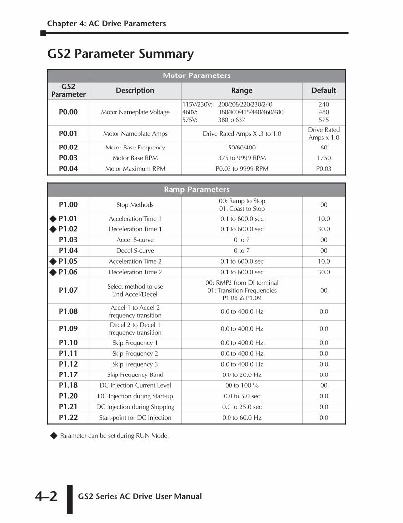
GS2 Parameter Summary
�� Parameter can be set during RUN Mode.
Ramp Parameters
P1.00 Stop Methods00: Ramp to Stop01: Coast to Stop
00
�� P1.01 Acceleration Time 1 0.1 to 600.0 sec 10.0
�� P1.02 Deceleration Time 1 0.1 to 600.0 sec 30.0
P1.03 Accel S-curve 0 to 7 00
P1.04 Decel S-curve 0 to 7 00
�� P1.05 Acceleration Time 2 0.1 to 600.0 sec 10.0
�� P1.06 Deceleration Time 2 0.1 to 600.0 sec 30.0
P1.07 Select method to use2nd Accel/Decel
00: RMP2 from DI terminal01: Transition Frequencies
P1.08 & P1.0900
P1.08 Accel 1 to Accel 2 frequency transition
0.0 to 400.0 Hz 0.0
P1.09 Decel 2 to Decel 1 frequency transition
0.0 to 400.0 Hz 0.0
P1.10 Skip Frequency 1 0.0 to 400.0 Hz 0.0
P1.11 Skip Frequency 2 0.0 to 400.0 Hz 0.0
P1.12 Skip Frequency 3 0.0 to 400.0 Hz 0.0
P1.17 Skip Frequency Band 0.0 to 20.0 Hz 0.0
P1.18 DC Injection Current Level 00 to 100 % 00
P1.20 DC Injection during Start-up 0.0 to 5.0 sec 0.0
P1.21 DC Injection during Stopping 0.0 to 25.0 sec 0.0
P1.22 Start-point for DC Injection 0.0 to 60.0 Hz 0.0
Motor ParametersGS2
Parameter Description Range Default
P0.00 Motor Nameplate Voltage115V/230V: 200/208/220/230/240460V: 380/400/415/440/460/480575V: 380 to 637
240480575
P0.01 Motor Nameplate Amps Drive Rated Amps X .3 to 1.0Drive RatedAmps x 1.0
P0.02 Motor Base Frequency 50/60/400 60
P0.03 Motor Base RPM 375 to 9999 RPM 1750
P0.04 Motor Maximum RPM P0.03 to 9999 RPM P0.03
GS2 Series AC Drive User Manual 4–3
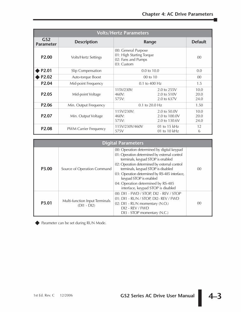
�� Parameter can be set during RUN Mode.
Digital Parameters
P3.00 Source of Operation Command
00: Operation determined by digital keypad01: Operation determined by external control
terminals, keypad STOP is enabled02: Operation determined by external control
terminals, keypad STOP is disabled03: Operation determined by RS-485 interface,
keypad STOP is enabled04: Operation determined by RS-485
interface, keypad STOP is disabled
00
P3.01 Multi-function Input Terminals(DI1 - DI2)
00: DI1 - FWD / STOP, DI2 - REV / STOP01: DI1 - RUN / STOP, DI2- REV / FWD02: DI1 - RUN momentary (N.O.)
DI2 - REV / FWDDI3 - STOP momentary (N.C.)
00
Volts/Hertz ParametersGS2
Parameter Description Range Default
P2.00 Volts/Hertz Settings
00: General Purpose01: High Starting Torque02: Fans and Pumps03: Custom
00
�� P2.01 Slip Compensation 0.0 to 10.0 0.0
�� P2.02 Auto-torque Boost 00 to 10 00
P2.04 Mid-point Frequency 0.1 to 400 Hz 1.5
P2.05 Mid-point Voltage115V/230V: 2.0 to 255V460V: 2.0 to 510V575V: 2.0 to 637V
10.020.024.0
P2.06 Min. Output Frequency 0.1 to 20.0 Hz 1.50
P2.07 Min. Output Voltage115V/230V: 2.0 to 50.0V460V: 2.0 to 100.0V575V: 2.0 to 130.6V
10.020.024.0
P2.08 PWM Carrier Frequency115V/230V/460V 01 to 15 kHz575V 01 to 10 kHz
126
Chapter 4: AC Drive Parameters
1st Ed. Rev. C 12/2006
Chapter 4: AC Drive Parameters
GS2 Series AC Drive User Manual4–4
�� Parameter can be set during RUN Mode.
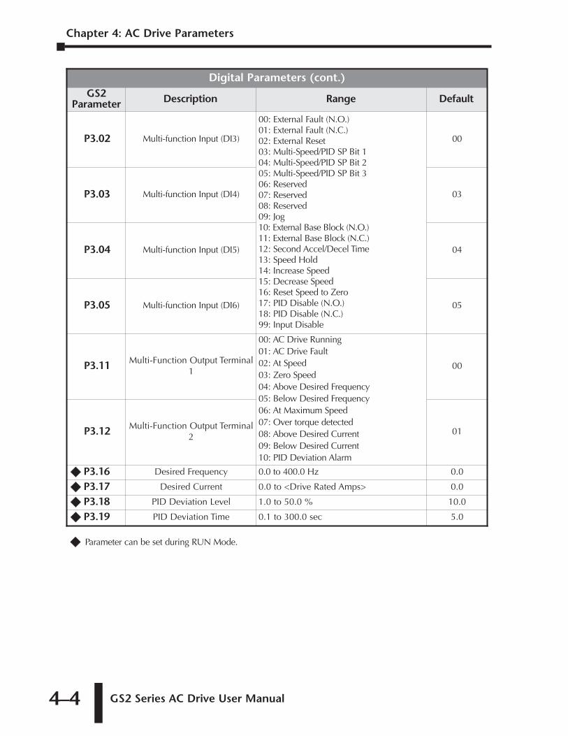
Digital Parameters (cont.)GS2
Parameter Description Range Default
P3.02 Multi-function Input (DI3)
00: External Fault (N.O.)01: External Fault (N.C.)02: External Reset03: Multi-Speed/PID SP Bit 104: Multi-Speed/PID SP Bit 205: Multi-Speed/PID SP Bit 306: Reserved07: Reserved08: Reserved09: Jog10: External Base Block (N.O.)11: External Base Block (N.C.)12: Second Accel/Decel Time13: Speed Hold14: Increase Speed15: Decrease Speed16: Reset Speed to Zero17: PID Disable (N.O.)18: PID Disable (N.C.)99: Input Disable
00
P3.03 Multi-function Input (DI4) 03
P3.04 Multi-function Input (DI5) 04
P3.05 Multi-function Input (DI6) 05
P3.11 Multi-Function Output Terminal1
00: AC Drive Running01: AC Drive Fault02: At Speed03: Zero Speed04: Above Desired Frequency05: Below Desired Frequency06: At Maximum Speed07: Over torque detected08: Above Desired Current09: Below Desired Current10: PID Deviation Alarm
00
P3.12 Multi-Function Output Terminal2
01
�� P3.16 Desired Frequency 0.0 to 400.0 Hz 0.0
�� P3.17 Desired Current 0.0 to <Drive Rated Amps> 0.0
�� P3.18 PID Deviation Level 1.0 to 50.0 % 10.0
�� P3.19 PID Deviation Time 0.1 to 300.0 sec 5.0
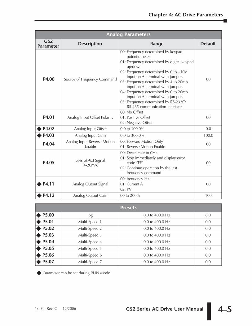
GS2 Series AC Drive User Manual 4–5
�� Parameter can be set during RUN Mode.
Presets�� P5.00 Jog 0.0 to 400.0 Hz 6.0
�� P5.01 Multi-Speed 1 0.0 to 400.0 Hz 0.0
�� P5.02 Multi-Speed 2 0.0 to 400.0 Hz 0.0
�� P5.03 Multi-Speed 3 0.0 to 400.0 Hz 0.0
�� P5.04 Multi-Speed 4 0.0 to 400.0 Hz 0.0
�� P5.05 Multi-Speed 5 0.0 to 400.0 Hz 0.0
�� P5.06 Multi-Speed 6 0.0 to 400.0 Hz 0.0
�� P5.07 Multi-Speed 7 0.0 to 400.0 Hz 0.0
Analog ParametersGS2
Parameter Description Range Default
P4.00 Source of Frequency Command
00: Frequency determined by keypadpotentiometer
01: Frequency determined by digital keypadup/down
02: Frequency determined by 0 to +10Vinput on AI terminal with jumpers
03: Frequency determined by 4 to 20mAinput on AI terminal with jumpers
04: Frequency determined by 0 to 20mAinput on AI terminal with jumpers
05: Frequency determined by RS-232C/RS-485 communication interface
00
P4.01 Analog Input Offset Polarity00: No Offset01: Positive Offset02: Negative Offset
00
�� P4.02 Analog Input Offset 0.0 to 100.0% 0.0
�� P4.03 Analog Input Gain 0.0 to 300.0% 100.0
P4.04 Analog Input Reverse MotionEnable
00: Forward Motion Only01: Reverse Motion Enable
00
P4.05 Loss of ACI Signal (4-20mA)
00: Decelerate to 0Hz01: Stop immediately and display error
code “EF”02: Continue operation by the last
frequency command
00
�� P4.11 Analog Output Signal00: frequency Hz01: Current A02: PV
00
�� P4.12 Analog Output Gain 00 to 200% 100
Chapter 4: AC Drive Parameters
1st Ed. Rev. C 12/2006
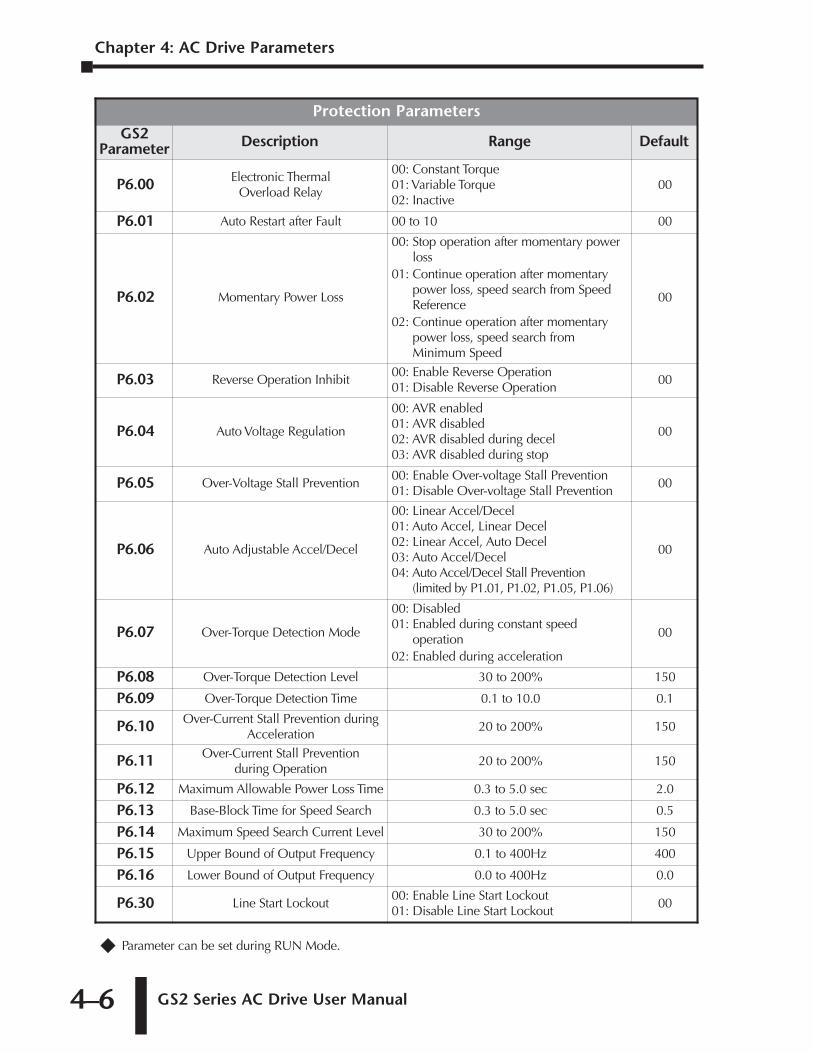
Chapter 4: AC Drive Parameters
GS2 Series AC Drive User Manual4–6
�� Parameter can be set during RUN Mode.
Protection ParametersGS2
Parameter Description Range Default
P6.00 Electronic Thermal Overload Relay
00: Constant Torque01: Variable Torque02: Inactive
00
P6.01 Auto Restart after Fault 00 to 10 00
P6.02 Momentary Power Loss
00: Stop operation after momentary powerloss
01: Continue operation after momentarypower loss, speed search from SpeedReference
02: Continue operation after momentarypower loss, speed search fromMinimum Speed
00
P6.03 Reverse Operation Inhibit00: Enable Reverse Operation01: Disable Reverse Operation
00
P6.04 Auto Voltage Regulation
00: AVR enabled01: AVR disabled02: AVR disabled during decel03: AVR disabled during stop
00
P6.05 Over-Voltage Stall Prevention00: Enable Over-voltage Stall Prevention01: Disable Over-voltage Stall Prevention
00
P6.06 Auto Adjustable Accel/Decel
00: Linear Accel/Decel01: Auto Accel, Linear Decel02: Linear Accel, Auto Decel03: Auto Accel/Decel04: Auto Accel/Decel Stall Prevention
(limited by P1.01, P1.02, P1.05, P1.06)
00
P6.07 Over-Torque Detection Mode
00: Disabled01: Enabled during constant speed
operation02: Enabled during acceleration
00
P6.08 Over-Torque Detection Level 30 to 200% 150
P6.09 Over-Torque Detection Time 0.1 to 10.0 0.1
P6.10 Over-Current Stall Prevention duringAcceleration
20 to 200% 150
P6.11 Over-Current Stall Prevention during Operation
20 to 200% 150
P6.12 Maximum Allowable Power Loss Time 0.3 to 5.0 sec 2.0
P6.13 Base-Block Time for Speed Search 0.3 to 5.0 sec 0.5
P6.14 Maximum Speed Search Current Level 30 to 200% 150
P6.15 Upper Bound of Output Frequency 0.1 to 400Hz 400
P6.16 Lower Bound of Output Frequency 0.0 to 400Hz 0.0
P6.30 Line Start Lockout00: Enable Line Start Lockout01: Disable Line Start Lockout
00
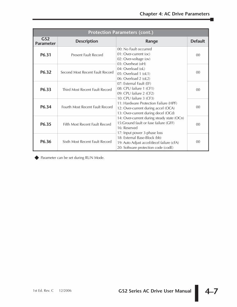
GS2 Series AC Drive User Manual 4–7
�� Parameter can be set during RUN Mode.
Protection Parameters (cont.)GS2
Parameter Description Range Default
P6.31 Present Fault Record
00: No Fault occurred01: Over-current (oc)02: Over-voltage (ov)03: Overheat (oH)04: Overload (oL)05: Overload 1 (oL1)06: Overload 2 (oL2)07: External Fault (EF)08: CPU failure 1 (CF1)09: CPU failure 2 (CF2)10: CPU failure 3 (CF3)11: Hardware Protection Failure (HPF)12: Over-current during accel (OCA)13: Over-current during decel (OCd)14: Over-current during steady state (OCn)15:Ground fault or fuse failure (GFF)16: Reserved17: Input power 3-phase loss18: External Base-Block (bb)19: Auto Adjust accel/decel failure (cFA)20: Software protection code (codE)
00
P6.32 Second Most Recent Fault Record 00
P6.33 Third Most Recent Fault Record 00
P6.34 Fourth Most Recent Fault Record 00
P6.35 Fifth Most Recent Fault Record 00
P6.36 Sixth Most Recent Fault Record 00
Chapter 4: AC Drive Parameters
1st Ed. Rev. C 12/2006
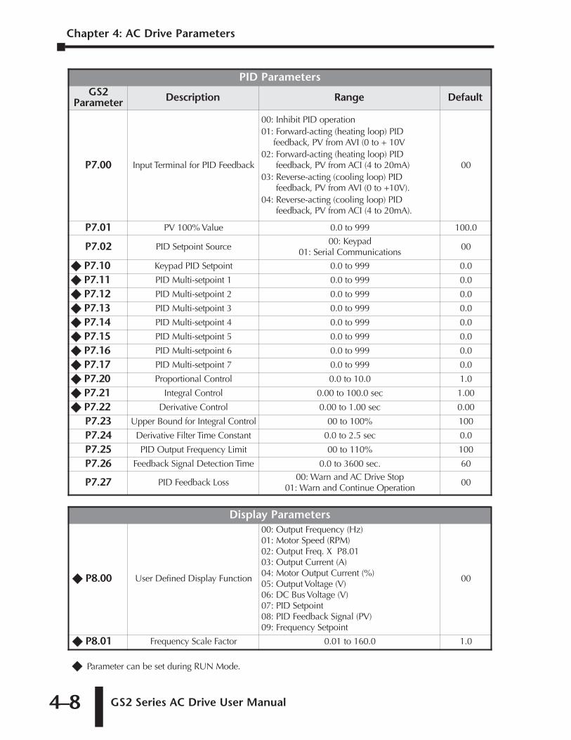
Chapter 4: AC Drive Parameters
GS2 Series AC Drive User Manual4–8
�� Parameter can be set during RUN Mode.
Display Parameters
�� P8.00 User Defined Display Function
00: Output Frequency (Hz)01: Motor Speed (RPM)02: Output Freq. X P8.0103: Output Current (A)04: Motor Output Current (%)05: Output Voltage (V)06: DC Bus Voltage (V)07: PID Setpoint08: PID Feedback Signal (PV) 09: Frequency Setpoint
00
�� P8.01 Frequency Scale Factor 0.01 to 160.0 1.0
PID ParametersGS2
Parameter Description Range Default
P7.00 Input Terminal for PID Feedback
00: Inhibit PID operation01: Forward-acting (heating loop) PID
feedback, PV from AVI (0 to + 10V02: Forward-acting (heating loop) PID
feedback, PV from ACI (4 to 20mA) 03: Reverse-acting (cooling loop) PID
feedback, PV from AVI (0 to +10V). 04: Reverse-acting (cooling loop) PID
feedback, PV from ACI (4 to 20mA).
00
P7.01 PV 100% Value 0.0 to 999 100.0
P7.02 PID Setpoint Source00: Keypad
01: Serial Communications00
�� P7.10 Keypad PID Setpoint 0.0 to 999 0.0
�� P7.11 PID Multi-setpoint 1 0.0 to 999 0.0
�� P7.12 PID Multi-setpoint 2 0.0 to 999 0.0
�� P7.13 PID Multi-setpoint 3 0.0 to 999 0.0
�� P7.14 PID Multi-setpoint 4 0.0 to 999 0.0
�� P7.15 PID Multi-setpoint 5 0.0 to 999 0.0
�� P7.16 PID Multi-setpoint 6 0.0 to 999 0.0
�� P7.17 PID Multi-setpoint 7 0.0 to 999 0.0
�� P7.20 Proportional Control 0.0 to 10.0 1.0
�� P7.21 Integral Control 0.00 to 100.0 sec 1.00
�� P7.22 Derivative Control 0.00 to 1.00 sec 0.00
P7.23 Upper Bound for Integral Control 00 to 100% 100
P7.24 Derivative Filter Time Constant 0.0 to 2.5 sec 0.0
P7.25 PID Output Frequency Limit 00 to 110% 100
P7.26 Feedback Signal Detection Time 0.0 to 3600 sec. 60
P7.27 PID Feedback Loss00: Warn and AC Drive Stop
01: Warn and Continue Operation00
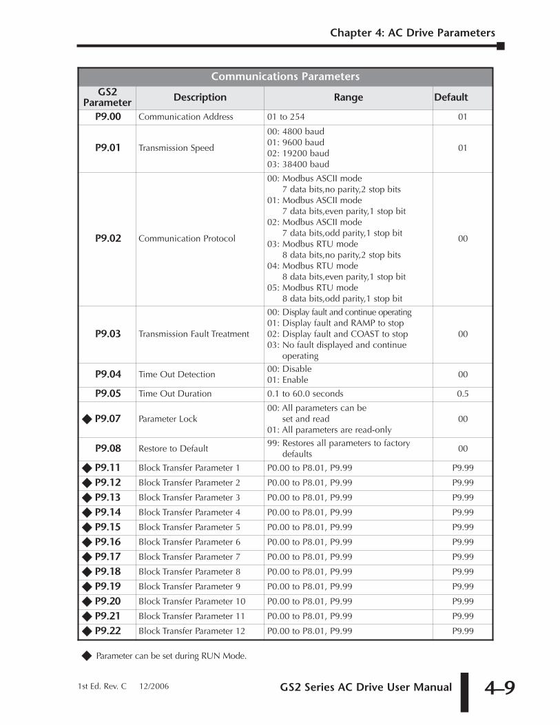
GS2 Series AC Drive User Manual 4–9
�� Parameter can be set during RUN Mode.
Communications ParametersGS2
Parameter Description Range Default
P9.00 Communication Address 01 to 254 01
P9.01 Transmission Speed
00: 4800 baud01: 9600 baud02: 19200 baud03: 38400 baud
01
P9.02 Communication Protocol
00: Modbus ASCII mode7 data bits,no parity,2 stop bits
01: Modbus ASCII mode7 data bits,even parity,1 stop bit
02: Modbus ASCII mode 7 data bits,odd parity,1 stop bit
03: Modbus RTU mode 8 data bits,no parity,2 stop bits
04: Modbus RTU mode 8 data bits,even parity,1 stop bit
05: Modbus RTU mode 8 data bits,odd parity,1 stop bit
00
P9.03 Transmission Fault Treatment
00: Display fault and continue operating01: Display fault and RAMP to stop02: Display fault and COAST to stop03: No fault displayed and continue
operating
00
P9.04 Time Out Detection00: Disable01: Enable
00
P9.05 Time Out Duration 0.1 to 60.0 seconds 0.5
�� P9.07 Parameter Lock00: All parameters can be
set and read01: All parameters are read-only
00
P9.08 Restore to Default99: Restores all parameters to factory
defaults00
�� P9.11 Block Transfer Parameter 1 P0.00 to P8.01, P9.99 P9.99
�� P9.12 Block Transfer Parameter 2 P0.00 to P8.01, P9.99 P9.99
�� P9.13 Block Transfer Parameter 3 P0.00 to P8.01, P9.99 P9.99
�� P9.14 Block Transfer Parameter 4 P0.00 to P8.01, P9.99 P9.99
�� P9.15 Block Transfer Parameter 5 P0.00 to P8.01, P9.99 P9.99
�� P9.16 Block Transfer Parameter 6 P0.00 to P8.01, P9.99 P9.99
�� P9.17 Block Transfer Parameter 7 P0.00 to P8.01, P9.99 P9.99
�� P9.18 Block Transfer Parameter 8 P0.00 to P8.01, P9.99 P9.99
�� P9.19 Block Transfer Parameter 9 P0.00 to P8.01, P9.99 P9.99
�� P9.20 Block Transfer Parameter 10 P0.00 to P8.01, P9.99 P9.99
�� P9.21 Block Transfer Parameter 11 P0.00 to P8.01, P9.99 P9.99
�� P9.22 Block Transfer Parameter 12 P0.00 to P8.01, P9.99 P9.99
Chapter 4: AC Drive Parameters
1st Ed. Rev. C 12/2006
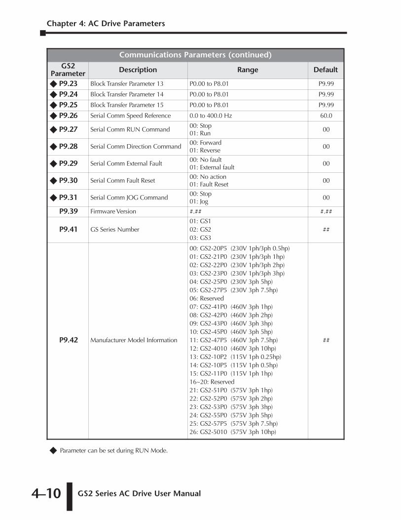
Chapter 4: AC Drive Parameters
GS2 Series AC Drive User Manual4–10
�� Parameter can be set during RUN Mode.
Communications Parameters (continued)GS2
Parameter Description Range Default
�� P9.23 Block Transfer Parameter 13 P0.00 to P8.01 P9.99
�� P9.24 Block Transfer Parameter 14 P0.00 to P8.01 P9.99
�� P9.25 Block Transfer Parameter 15 P0.00 to P8.01 P9.99
�� P9.26 Serial Comm Speed Reference 0.0 to 400.0 Hz 60.0
�� P9.27 Serial Comm RUN Command00: Stop01: Run
00
�� P9.28 Serial Comm Direction Command00: Forward01: Reverse
00
�� P9.29 Serial Comm External Fault00: No fault01: External fault
00
�� P9.30 Serial Comm Fault Reset00: No action01: Fault Reset
00
�� P9.31 Serial Comm JOG Command00: Stop01: Jog
00
P9.39 Firmware Version #.## #.##
P9.41 GS Series Number01: GS102: GS203: GS3
##
P9.42 Manufacturer Model Information
00: GS2-20P5 (230V 1ph/3ph 0.5hp)01: GS2-21P0 (230V 1ph/3ph 1hp)02: GS2-22P0 (230V 1ph/3ph 2hp)03: GS2-23P0 (230V 1ph/3ph 3hp)04: GS2-25P0 (230V 3ph 5hp)05: GS2-27P5 (230V 3ph 7.5hp)06: Reserved07: GS2-41P0 (460V 3ph 1hp)08: GS2-42P0 (460V 3ph 2hp)09: GS2-43P0 (460V 3ph 3hp)10: GS2-45P0 (460V 3ph 5hp)11: GS2-47P5 (460V 3ph 7.5hp)12: GS2-4010 (460V 3ph 10hp)13: GS2-10P2 (115V 1ph 0.25hp)14: GS2-10P5 (115V 1ph 0.5hp)15: GS2-11P0 (115V 1ph 1hp)16~20: Reserved21: GS2-51P0 (575V 3ph 1hp)22: GS2-52P0 (575V 3ph 2hp)23: GS2-53P0 (575V 3ph 3hp)24: GS2-55P0 (575V 3ph 5hp)25: GS2-57P5 (575V 3ph 7.5hp)26: GS2-5010 (575V 3ph 10hp)
##
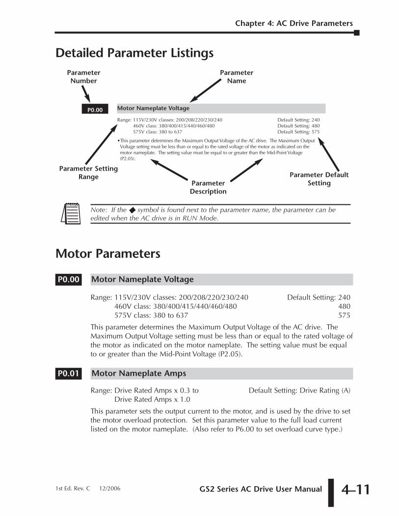
GS2 Series AC Drive User Manual 4–11
Chapter 4: AC Drive Parameters
1st Ed. Rev. C 12/2006
Detailed Parameter Listings
Motor Parameters
Motor Nameplate Voltage
Range: 115V/230V classes: 200/208/220/230/240 Default Setting: 240460V class: 380/400/415/440/460/480 480575V class: 380 to 637 575
This parameter determines the Maximum Output Voltage of the AC drive. TheMaximum Output Voltage setting must be less than or equal to the rated voltage ofthe motor as indicated on the motor nameplate. The setting value must be equalto or greater than the Mid-Point Voltage (P2.05).
Motor Nameplate Amps
Range: Drive Rated Amps x 0.3 to Default Setting: Drive Rating (A)Drive Rated Amps x 1.0
This parameter sets the output current to the motor, and is used by the drive to setthe motor overload protection. Set this parameter value to the full load currentlisted on the motor nameplate. (Also refer to P6.00 to set overload curve type.)
P0.01
P0.00
Note: If the � symbol is found next to the parameter name, the parameter can beedited when the AC drive is in RUN Mode.
Motor Nameplate Voltage
Range: 115V/230V classes: 200/208/220/230/240 Default Setting: 240460V class: 380/400/415/440/460/480 Default Setting: 480575V class: 380 to 637 Default Setting: 575
•This parameter determines the Maximum Output Voltage of the AC drive. The Maximum OutputVoltage setting must be less than or equal to the rated voltage of the motor as indicated on themotor nameplate. The setting value must be equal to or greater than the Mid-Point Voltage(P2.05).
ParameterNumber
Parameter SettingRange
ParameterDescription
Parameter DefaultSetting
ParameterName
P0.00
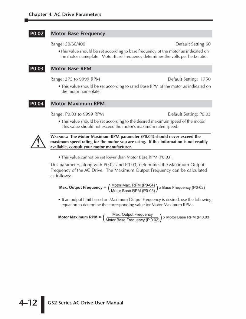
Chapter 4: AC Drive Parameters
GS2 Series AC Drive User Manual4–12
Motor Base Frequency
Range: 50/60/400 Default Setting 60
•This value should be set according to base frequency of the motor as indicated onthe motor nameplate. Motor Base Frequency determines the volts per hertz ratio.
Motor Base RPM
Range: 375 to 9999 RPM Default Setting: 1750
• This value should be set according to rated Base RPM of the motor as indicated onthe motor nameplate.
Motor Maximum RPM
Range: P0.03 to 9999 RPM Default Setting: P0.03
• This value should be set according to the desired maximum speed of the motor.This value should not exceed the motor’s maximum rated speed.
• This value cannot be set lower than Motor Base RPM (P0.03).
This parameter, along with P0.02 and P0.03, determines the Maximum OutputFrequency of the AC Drive. The Maximum Output Frequency can be calculatedas follows:
• If an output limit based on Maximum Output Frequency is desired, use the followingequation to determine the corresponding value for Motor Maximum RPM:
x Motor Base RPM (P 0.03)Motor Maximum RPM = Max. Output FrequencyMotor Base Frequency (P 0.02)( )
x Base Frequency (P0-02)Max. Output Frequency = Motor Max. RPM (P0-04)Motor Base RPM (P0-03)( )
WARNING: The Motor Maximum RPM parameter (P0.04) should never exceed themaximum speed rating for the motor you are using. If this information is not readilyavailable, consult your motor manufacturer.
P0.04
P0.03
P0.02
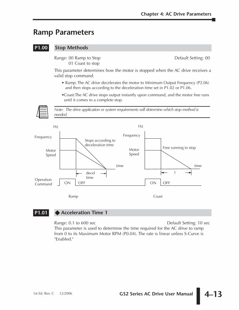
GS2 Series AC Drive User Manual 4–13
Chapter 4: AC Drive Parameters
1st Ed. Rev. C 12/2006
Ramp Parameters
Stop Methods
Range: 00 Ramp to Stop Default Setting: 0001 Coast to stop
This parameter determines how the motor is stopped when the AC drive receives avalid stop command.
• Ramp: The AC drive decelerates the motor to Minimum Output Frequency (P2.06)and then stops according to the deceleration time set in P1.02 or P1.06.
•Coast:The AC drive stops output instantly upon command, and the motor free runsuntil it comes to a complete stop.
�� Acceleration Time 1
Range: 0.1 to 600 sec Default Setting: 10 secThis parameter is used to determine the time required for the AC drive to rampfrom 0 to its Maximum Motor RPM (P0.04). The rate is linear unless S-Curve is"Enabled."
P1.01
MotorSpeed
ON OFF
decel time
Ramp
time
Frequency
MotorSpeed
time
ON OFF
?
Coast
Free running to stop
Stops according to deceleration time
Hz Hz
Frequency
Operation Command
Note: The drive application or system requirements will determine which stop method isneeded.
P1.00
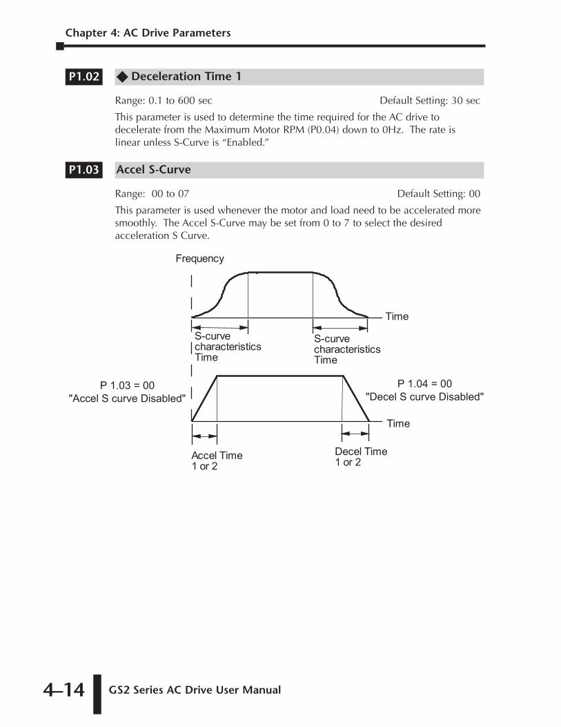
Chapter 4: AC Drive Parameters
GS2 Series AC Drive User Manual4–14
�� Deceleration Time 1
Range: 0.1 to 600 sec Default Setting: 30 sec
This parameter is used to determine the time required for the AC drive todecelerate from the Maximum Motor RPM (P0.04) down to 0Hz. The rate islinear unless S-Curve is “Enabled.”
Accel S-Curve
Range: 00 to 07 Default Setting: 00
This parameter is used whenever the motor and load need to be accelerated moresmoothly. The Accel S-Curve may be set from 0 to 7 to select the desiredacceleration S Curve.
Decel Time
1 or 2Accel Time
1 or 2
S-curve
characteristics
Time
S-curve
characteristics
Time
Time
Time
Frequency
P 1.03 = 00
"Accel S curve Disabled"
P 1.04 = 00
"Decel S curve Disabled"
P1.03
P1.02

GS2 Series AC Drive User Manual 4–15
Chapter 4: AC Drive Parameters
1st Ed. Rev. C 12/2006
Decel S-Curve
Range: 00 to 07 Default Setting: 00
This parameter is used whenever the motor and load need to be decelerated moresmoothly. The Decel S-Curve may be set from 00 to 07 to select the desireddeceleration S-Curve.
Note: From the diagram shown below, the original setting accel/decel time will befor reference when the function of the S-curve is enabled. The actual accel/deceltime will be determined based on the S-curve selected (1 to 7).
�� Acceleration Time 2
Range: 0.1 to 600 sec Default Setting: 10.0
•The Second Acceleration Time determines the time for the AC drive to acceleratefrom 0 RPM to Maximum Motor RPM (P0.04). Acceleration Time 2 (P1.05) can beselected using a multi-function input terminal or frequency transition (P1.07).
�� Deceleration Time 2
Range: 0.1 to 600 sec Default Setting: 30 sec
•The Second Deceleration Time determines the time for the AC drive to deceleratefrom Maximum Motor RPM (P0.04) to 0 RPM. Deceleration Time 2 (P1.06) can beselected using a multi-function input terminal or frequency transition (P1.07).
P1.06
P1.05
Time
S curve is disabled in (1), (2)P 1.03 sets S curve for (3) P 1.04 sets S curve for (4)
(4)(3)
(4)(3)
(2)(1)
(2)(1)
P 1.03 P 1.04Frequency
P1.04
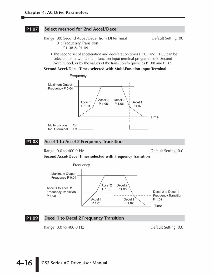
Chapter 4: AC Drive Parameters
GS2 Series AC Drive User Manual4–16
Select method for 2nd Accel/Decel
Range: 00: Second Accel/Decel from DI terminal Default Setting: 0001: Frequency Transition
P1.08 & P1.09
• The second set of acceleration and deceleration times P1.05 and P1.06 can beselected either with a multi-function input terminal programmed to SecondAccel/Decel, or by the values of the transition frequencies P1.08 and P1.09
Second Accel/Decel Times selected with Multi-Function Input Terminal
Accel 1 to Accel 2 Frequency Transition
Range: 0.0 to 400.0 Hz Default Setting: 0.0Second Accel/Decel Times selected with Frequency Transition
Decel 1 to Decel 2 Frequency Transition
Range: 0.0 to 400.0 Hz Default Setting: 0.0
P1.09
Frequency
Time
Accel 1 P 1.01
Accel 2 P 1.05
Decel 2 P 1.06
Decel 1 P 1.02
Maximum Output Frequency P 0.04
Accel 1 to Accel 2Frequency TransitionP 1.08
Decel 2 to Decel 1Frequency TransitionP 1.09
P1.08
Frequency
Time
Multi-function Input Terminal
OnOff
Accel 1 P 1.01
Accel 2 P 1.05
Decel 2 P 1.06 Decel 1
P 1.02
Maximum Output Frequency P 0.04
P1.07
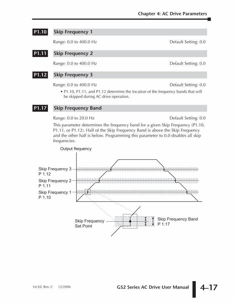
GS2 Series AC Drive User Manual 4–17
Chapter 4: AC Drive Parameters
1st Ed. Rev. C 12/2006
Skip Frequency 1
Range: 0.0 to 400.0 Hz Default Setting: 0.0
Skip Frequency 2
Range: 0.0 to 400.0 Hz Default Setting: 0.0
Skip Frequency 3
Range: 0.0 to 400.0 Hz Default Setting: 0.0
• P1.10, P1.11, and P1.12 determine the location of the frequency bands that willbe skipped during AC drive operation.
Skip Frequency Band
Range: 0.0 to 20.0 Hz Default Setting: 0.0
This parameter determines the frequency band for a given Skip Frequency (P1.10,P1.11, or P1.12). Half of the Skip Frequency Band is above the Skip Frequencyand the other half is below. Programming this parameter to 0.0 disables all skipfrequencies.
Output frequency
Skip Frequency 1
P 1.10
Skip Frequency 2
P 1.11
Skip Frequency 3
P 1.12
Skip Frequency
Set Point
Skip Frequency Band
P 1.17
P1.17
P1.12
P1.11
P1.10
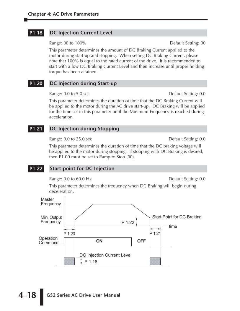
Chapter 4: AC Drive Parameters
GS2 Series AC Drive User Manual4–18
DC Injection Current Level
Range: 00 to 100% Default Setting: 00
This parameter determines the amount of DC Braking Current applied to themotor during start-up and stopping. When setting DC Braking Current, pleasenote that 100% is equal to the rated current of the drive. It is recommended tostart with a low DC Braking Current Level and then increase until proper holdingtorque has been attained.
DC Injection during Start-up
Range: 0.0 to 5.0 sec Default Setting: 0.0
This parameter determines the duration of time that the DC Braking Current willbe applied to the motor during the AC drive start-up. DC Braking will be appliedfor the time set in this parameter until the Minimum Frequency is reached duringacceleration.
DC Injection during Stopping
Range: 0.0 to 25.0 sec Default Setting: 0.0
This parameter determines the duration of time that the DC braking voltage willbe applied to the motor during stopping. If stopping with DC Braking is desired,then P1.00 must be set to Ramp to Stop (00).
Start-point for DC Injection
Range: 0.0 to 60.0 Hz Default Setting: 0.0
This parameter determines the frequency when DC Braking will begin duringdeceleration.
Operation
Command
Min. Output
Frequency
Start-Point for DC Braking
time
DC Injection Current Level
Master
Frequency
ON OFF
P 1.22
P 1.20
P 1.21
P 1.18
P1.22
P1.21
P1.20
P1.18
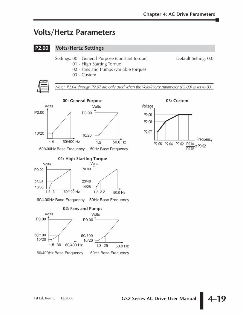
GS2 Series AC Drive User Manual 4–19
Chapter 4: AC Drive Parameters
Volts/Hertz Parameters
Volts/Hertz Settings
Settings: 00 - General Purpose (constant torque) Default Setting: 0.001 - High Starting Torque02 - Fans and Pumps (variable torque)03 - Custom
Volts
60/400 Hz10/20
1.5
P0.00Volts
50.0 Hz10/20
1.3
P0.00
25
50/100
30
50/100
60/400Hz Base Frequency 50Hz Base Frequency
02: Fans and Pumps
50.0 Hz1.3 2.2
Volts
60/400 Hz18/36
1.5
P0.00
3
23/46
Volts
14/28
P0.00
23/46
60/400Hz Base Frequency 50Hz Base Frequency
01: High Starting Torque
Volts
60/400 Hz
10/20
1.5
P0.00Volts
50.0 Hz
10/20
1.5
P0.00
60/400Hz Base Frequency 50Hz Base Frequency
00: General Purpose
Frequency
Voltage
P2.04 P0.02 P0.04P0.03
P0.00
P2.05
P2.07
P2.06 x P0.02
03: Custom
Note: P2.04 through P2.07 are only used when the Volts/Hertz parameter (P2.00) is set to 03.
P2.00
1st Ed. Rev. C 12/2006
Chapter 4: AC Drive Parameters
GS2 Series AC Drive User Manual4–20
�� Slip Compensation
Range: 0.0 to 10.0 Default Setting: 0.0
When controlling an asynchronous induction motor, load on the AC drive willincrease causing an increase in slip. This parameter may be used to compensatethe nominal slip within a range of 0 to 10. When the output current of the ACdrive is greater than the Motor Nameplate Amps (P0.01), the AC drive will adjustits output frequency according to this parameter.
�� Auto-torque Boost
Range: 00 to 10 Default Setting: 00
This parameter functions similarly to the P2.00-01 High Starting Torque V/Hzsetting, except that this parameter uses less current than does P2.00-01. P2.00-01boosts starting torque by increasing current at every start beyond what is requiredto move the load. P2.02 Auto-torque Boost increases the current only as requiredto move the load. The proper setting for P2.02 is determined by trial and error.
Mid-point Frequency
Range: 0.1 to 400 Hz Default Setting: 1.5
This parameter sets the Mid-Point Frequency of V/F curve. With this setting, theV/F ratio between Minimum Frequency and Mid-Point frequency can bedetermined.This parameter must be greater than or equal to the Minimum Output Frequency(P2.06) and less than or equal to the Maximum Voltage Frequency (P0.02). Thisparameter is used only when the Volts/Hertz parameter (P2.00) is set to 03.
Mid-point Voltage
Range: 115V/230V: 2.0 to 255V Default Setting: 10.0460V: 2.0 to 510V 20.0575V: 2.0 to 637V 24.0
This parameter sets the Mid-Point Voltage of any V/F curve. With this setting, theV/F ratio between Minimum Frequency and Mid-Point Frequency can bedetermined.This parameter must be greater than or equal to the Minimum Output Voltage (P2.07) and less than or equal to the Maximum Output Voltage (P0.00). Thisparameter is used only when the Volts/Hertz parameter (P2.00) is set to 03.
P2.05
P2.04
P2.04 through P2.07 are used only when the Volts/Hertz parameter (P2.00) is set to 03.
P2.02
P2.01
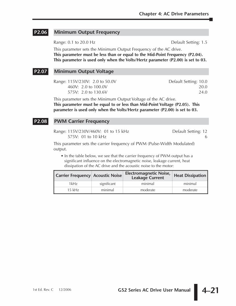
GS2 Series AC Drive User Manual 4–21
Chapter 4: AC Drive Parameters
1st Ed. Rev. C 12/2006
Minimum Output Frequency
Range: 0.1 to 20.0 Hz Default Setting: 1.5
This parameter sets the Minimum Output Frequency of the AC drive.This parameter must be less than or equal to the Mid-Point Frequency (P2.04).This parameter is used only when the Volts/Hertz parameter (P2.00) is set to 03.
Minimum Output Voltage
Range: 115V/230V: 2.0 to 50.0V Default Setting: 10.0460V: 2.0 to 100.0V 20.0575V: 2.0 to 130.6V 24.0
This parameter sets the Minimum Output Voltage of the AC drive.This parameter must be equal to or less than Mid-Point Voltage (P2.05). Thisparameter is used only when the Volts/Hertz parameter (P2.00) is set to 03.
PWM Carrier Frequency
Range: 115V/230V/460V: 01 to 15 kHz Default Setting: 12575V: 01 to 10 kHz 6
This parameter sets the carrier frequency of PWM (Pulse-Width Modulated)output.
• In the table below, we see that the carrier frequency of PWM output has asignificant influence on the electromagnetic noise, leakage current, heatdissipation of the AC drive and the acoustic noise to the motor:
Carrier Frequency Acoustic Noise Electromagnetic Noise,Leakage Current Heat Dissipation
1kHz significant minimal minimal
15 kHz minimal moderate moderate
P2.08
P2.07
P2.06
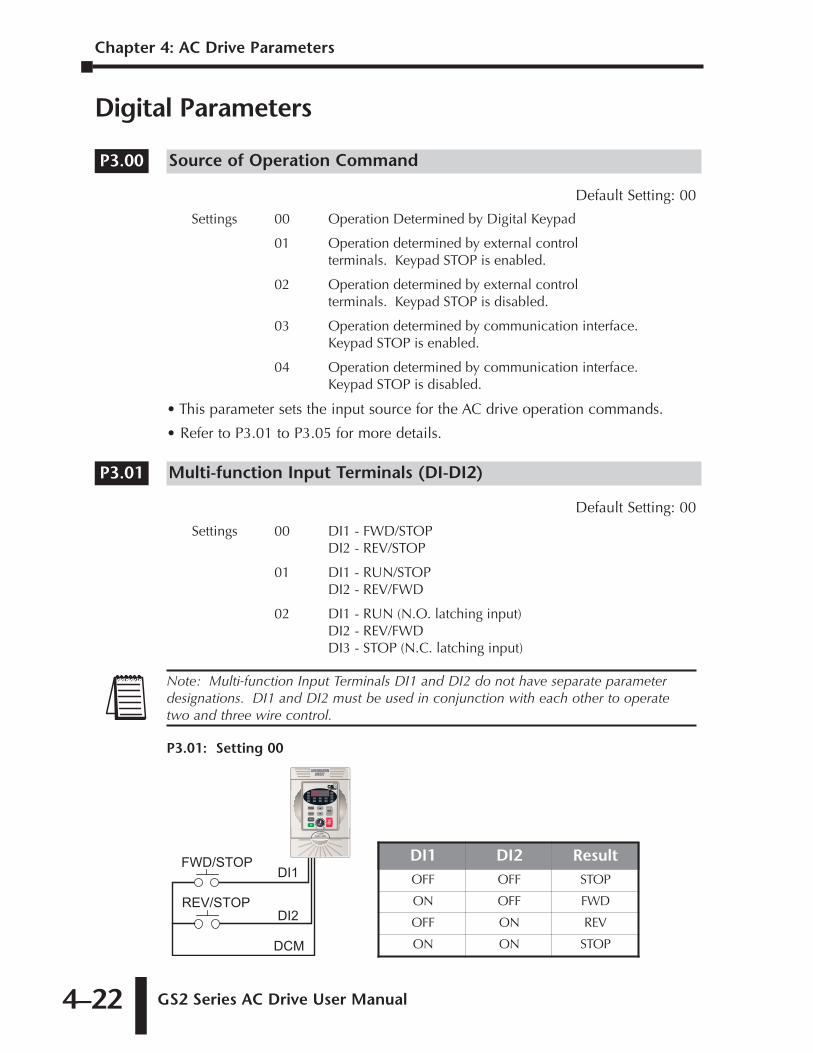
Chapter 4: AC Drive Parameters
GS2 Series AC Drive User Manual4–22
Digital Parameters
Source of Operation Command
Default Setting: 00
Settings 00 Operation Determined by Digital Keypad
01 Operation determined by external controlterminals. Keypad STOP is enabled.
02 Operation determined by external controlterminals. Keypad STOP is disabled.
03 Operation determined by communication interface. Keypad STOP is enabled.
04 Operation determined by communication interface. Keypad STOP is disabled.
• This parameter sets the input source for the AC drive operation commands.
• Refer to P3.01 to P3.05 for more details.
Multi-function Input Terminals (DI-DI2)
Default Setting: 00
Settings 00 DI1 - FWD/STOPDI2 - REV/STOP
01 DI1 - RUN/STOPDI2 - REV/FWD
02 DI1 - RUN (N.O. latching input)DI2 - REV/FWDDI3 - STOP (N.C. latching input)
DI1 DI2 ResultOFF OFF STOP
ON OFF FWD
OFF ON REV
ON ON STOP
REV/STOP
FWD/STOP
DCM
DI2
DI1
P3.01: Setting 00
Note: Multi-function Input Terminals DI1 and DI2 do not have separate parameterdesignations. DI1 and DI2 must be used in conjunction with each other to operatetwo and three wire control.
P3.01
P3.00
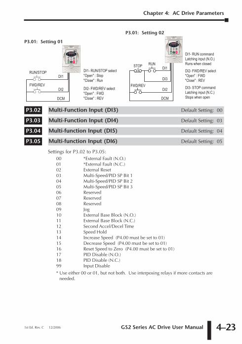
GS2 Series AC Drive User Manual 4–23
Chapter 4: AC Drive Parameters
1st Ed. Rev. C 12/2006
Multi-Function Input (DI3) Default Setting: 00
Multi-Function Input (DI4) Default Setting: 03
Multi-function Input (DI5) Default Setting: 04
Multi-function Input (DI6) Default Setting: 05
Settings for P3.02 to P3.05:00 *External Fault (N.O.)01 *External Fault (N.C.)02 External Reset03 Multi-Speed/PID SP Bit 104 Multi-Speed/PID SP Bit 205 Multi-Speed/PID SP Bit 306 Reserved07 Reserved08 Reserved09 Jog10 External Base Block (N.O.)11 External Base Block (N.C.)12 Second Accel/Decel Time13 Speed Hold14 Increase Speed (P4.00 must be set to 01)15 Decrease Speed (P4.00 must be set to 01)16 Reset Speed to Zero (P4.00 must be set to 01)17 PID Disable (N.O.)18 PID Disable (N.C.)99 Input Disable
* Use either 00 or 01, but not both. Use interposing relays if more contacts areneeded.
P3.01: Setting 02
DI1- RUN/STOP select"Open" : Stop"Close" : Run
DI2- FWD/REV select"Open" : FWD"Close" : REV
FWD/REV
RUN/STOP
DCM
DI2
DI1
P3.01: Setting 01
P3.05
P3.04
P3.03
P3.02
DI1- RUN commandLatching input (N.O.)Runs when closed
DI3- STOP commandLatching input (N.C.)Stops when open
DI2
DI3
DI1
DCM
STOP RUN
FWD/REV
DI2- FWD/REV select"Open" : FWD"Close" : REV
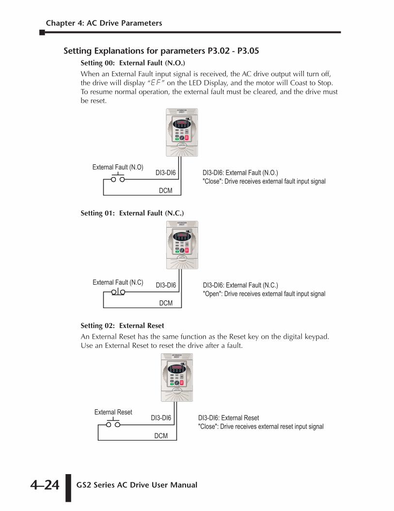
Chapter 4: AC Drive Parameters
GS2 Series AC Drive User Manual4–24
Setting Explanations for parameters P3.02 - P3.05Setting 00: External Fault (N.O.)
When an External Fault input signal is received, the AC drive output will turn off,the drive will display “EF” on the LED Display, and the motor will Coast to Stop.To resume normal operation, the external fault must be cleared, and the drive mustbe reset.
Setting 01: External Fault (N.C.)
Setting 02: External Reset
An External Reset has the same function as the Reset key on the digital keypad.Use an External Reset to reset the drive after a fault.
DI3-DI6: External Reset"Close": Drive receives external reset input signal
DI3-DI6
DCM
External Reset
DI3-DI6: External Fault (N.C.)"Open": Drive receives external fault input signal
DI3-DI6
DCM
External Fault (N.C)
DI3-DI6: External Fault (N.O.)"Close": Drive receives external fault input signal
DI3-DI6
DCM
External Fault (N.O)
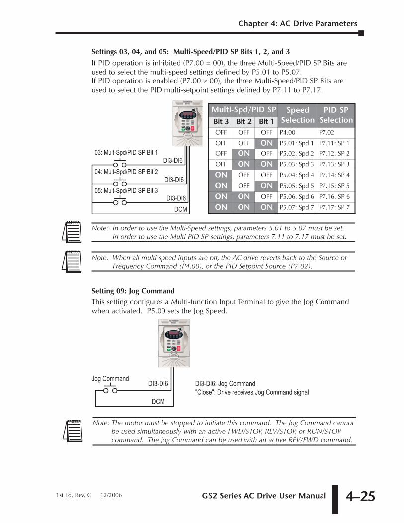
GS2 Series AC Drive User Manual 4–25
Chapter 4: AC Drive Parameters
1st Ed. Rev. C 12/2006
Settings 03, 04, and 05: Multi-Speed/PID SP Bits 1, 2, and 3
If PID operation is inhibited (P7.00 = 00), the three Multi-Speed/PID SP Bits areused to select the multi-speed settings defined by P5.01 to P5.07. If PID operation is enabled (P7.00 ≠ 00), the three Multi-Speed/PID SP Bits areused to select the PID multi-setpoint settings defined by P7.11 to P7.17.
Setting 09: Jog Command
This setting configures a Multi-function Input Terminal to give the Jog Commandwhen activated. P5.00 sets the Jog Speed.
Note: The motor must be stopped to initiate this command. The Jog Command cannotbe used simultaneously with an active FWD/STOP, REV/STOP, or RUN/STOPcommand. The Jog Command can be used with an active REV/FWD command.
DI3-DI6: Jog Command"Close": Drive receives Jog Command signal
DI3-DI6
DCM
Jog Command
Note: When all multi-speed inputs are off, the AC drive reverts back to the Source ofFrequency Command (P4.00), or the PID Setpoint Source (P7.02).
Note: In order to use the Multi-Speed settings, parameters 5.01 to 5.07 must be set.In order to use the Multi-PID SP settings, parameters 7.11 to 7.17 must be set.
Multi-Spd/PID SP SpeedSelection
PID SPSelectionBit 3 Bit 2 Bit 1
OFF OFF OFF P4.00 P7.02
OFF OFF ON P5.01: Spd 1 P7.11: SP 1
OFF ON OFF P5.02: Spd 2 P7.12: SP 2
OFF ON ON P5.03: Spd 3 P7.13: SP 3
ON OFF OFF P5.04: Spd 4 P7.14: SP 4
ON OFF ON P5.05: Spd 5 P7.15: SP 5
ON ON OFF P5.06: Spd 6 P7.16: SP 6
ON ON ON P5.07: Spd 7 P7.17: SP 7
DI3-DI6
DCM
03: Mult-Spd/PID SP Bit 1
DI3-DI6
DI3-DI605: Mult-Spd/PID SP Bit 3
04: Mult-Spd/PID SP Bit 2
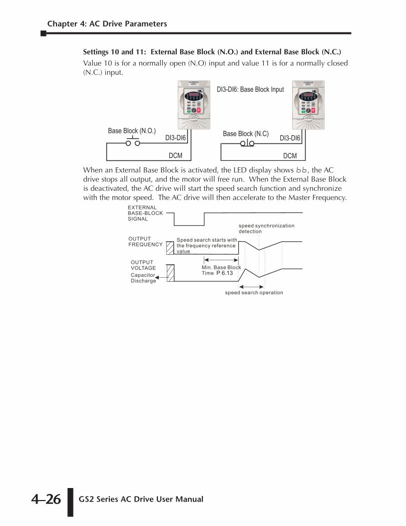
Chapter 4: AC Drive Parameters
GS2 Series AC Drive User Manual4–26
Settings 10 and 11: External Base Block (N.O.) and External Base Block (N.C.)
Value 10 is for a normally open (N.O) input and value 11 is for a normally closed(N.C.) input.
When an External Base Block is activated, the LED display shows bb, the ACdrive stops all output, and the motor will free run. When the External Base Blockis deactivated, the AC drive will start the speed search function and synchronizewith the motor speed. The AC drive will then accelerate to the Master Frequency.
P 6.13
Base Block (N.C)
DI3-DI6: Base Block Input
Base Block (N.O.)
DCM
DI3-DI6
DCM
DI3-DI6
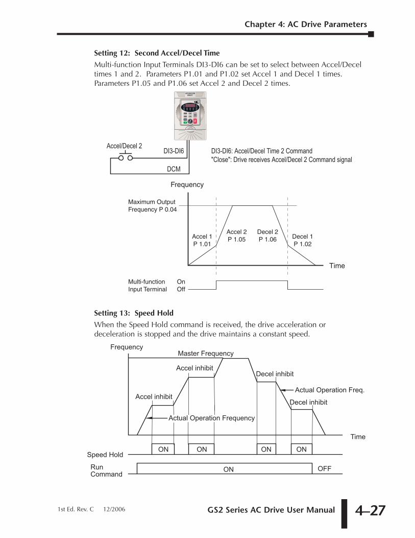
GS2 Series AC Drive User Manual 4–27
Chapter 4: AC Drive Parameters
1st Ed. Rev. C 12/2006
Setting 12: Second Accel/Decel Time
Multi-function Input Terminals DI3-DI6 can be set to select between Accel/Deceltimes 1 and 2. Parameters P1.01 and P1.02 set Accel 1 and Decel 1 times.Parameters P1.05 and P1.06 set Accel 2 and Decel 2 times.
Setting 13: Speed Hold
When the Speed Hold command is received, the drive acceleration ordeceleration is stopped and the drive maintains a constant speed.
Actual Operation Freq.
Time
ON ONON
ON
ON
OFF
Master Frequency
Accel inhibit
Decel inhibit
Decel inhibit
Accel inhibit
Actual Operation Frequency
Frequency
Run Command
Speed Hold
Frequency
Time
Multi-function Input Terminal
OnOff
Accel 1 P 1.01
Accel 2 P 1.05
Decel 2 P 1.06 Decel 1
P 1.02
Maximum Output Frequency P 0.04
DI3-DI6: Accel/Decel Time 2 Command"Close": Drive receives Accel/Decel 2 Command signal
DI3-DI6
DCM
Accel/Decel 2
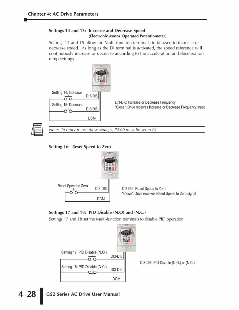
Chapter 4: AC Drive Parameters
GS2 Series AC Drive User Manual4–28
Settings 14 and 15: Increase and Decrease Speed (Electronic Motor Operated Potentiometer)
Settings 14 and 15 allow the Multi-function terminals to be used to increase ordecrease speed. As long as the DI terminal is activated, the speed reference willcontinuously increase or decrease according to the acceleration and decelerationramp settings.
Setting 16: Reset Speed to Zero
Settings 17 and 18: PID Disable (N.O) and (N.C.)
Settings 17 and 18 set the Multi-function terminals to disable PID operation.
Setting 18: PID Disable (N.C.)
Setting 17: PID Disable (N.O.)
DCM
DI3-DI6
DI3-DI6DI3-DI6: PID Disable (N.O.) or (N.C.)
DI3-DI6: Reset Speed to Zero"Close": Drive receives Reset Speed to Zero signal
DI3-DI6
DCM
Reset Speed to Zero
Note: In order to use these settings, P4.00 must be set to 01.
Setting 15: Decrease
Setting 14: Increase
DCM
DI3-DI6
DI3-DI6DI3-DI6: Increase or Decrease Frequency"Close": Drive receives Increase or Decrease Frequency Input
GS2 Series AC Drive User Manual 4–29
Chapter 4: AC Drive Parameters
1st Ed. Rev. C 12/2006
Setting 99: Multi-Function Input Disable
Setting a Multi-Function Input to 99 will disable that input. The purpose of thisfunction is to provide isolation for unused Multi-Function Input Terminals. Anyunused terminals should be programmed to 99 to make sure they have no effecton drive operation.
Note: Any unused terminals should be programmed to 99 to make sure they have noeffect on drive operation.
Chapter 4: AC Drive Parameters
GS2 Series AC Drive User Manual4–30
Multi-function Output Terminal 1
Default Setting: 00
Multi-function Output Terminal 2
Default Setting: 01
Settings for P3.11 to P3.12:
Settings: 00 AC Drive Running01 AC Drive Fault02 At Speed03 Zero Speed04 Above Desired Frequency (P3.16)05 Below Desired Frequency (P3.16)06 At Maximum Speed (P0.02)07 Over Torque Detected08 Above Desired Current (P3.17)09 Below Desired Current (P3.17)10 PID Deviation Alarm (P3.18 and P3.19)
Setting Function Explanations:00: AC Drive Running—The terminal will be activated when there is an output
from the drive.
01: AC Drive Fault—The terminal will be activated when one of the faults listedunder parameters P6.31 through P6.36 occurs.
02: At Speed—The terminal will be activated when the AC drive attains the CommandFrequency (P4.00 or P5.01~P5.07).
03: Zero Speed—The output will be activated when Command Frequency (P4.00or P5.01~P5.07) is lower than the Minimum Output Frequency (P2.06).
04: Above Desired Frequency—The output will be activated when the AC drive isabove the Desired Frequency (P3.16).
05: Below Desired Frequency—The output will be activated when the AC drive isbelow the Desired Frequency (P3.16).
06: At Maximum Speed—The output will be activated when the AC drive reachesMotor Maximum RPM (P0.04).
07: Over Torque Detected—The output will be activated when the AC drivereaches the Over-torque Detection Level (P6.08), and exceeds this level for atime greater than the Over-torque Detection Time (P6.09).
08: Above Desired Current—The output will be activated when the AC drive is abovethe Desired Current (P3.17).
09: Below Desired Current—The output will be activated when the AC drive is belowthe Desired Current (P3.17).
10: PID Deviation Alarm—The output will be activated when the AC driveexceeds the PID Deviation Level (P3.18) for longer than the PID DeviationTime (P3.19).
P3.12
P3.11
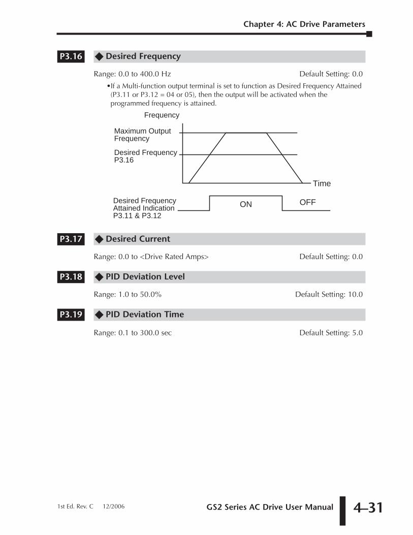
GS2 Series AC Drive User Manual 4–31
Chapter 4: AC Drive Parameters
1st Ed. Rev. C 12/2006
�� Desired Frequency
Range: 0.0 to 400.0 Hz Default Setting: 0.0
•If a Multi-function output terminal is set to function as Desired Frequency Attained(P3.11 or P3.12 = 04 or 05), then the output will be activated when theprogrammed frequency is attained.
�� Desired Current
Range: 0.0 to <Drive Rated Amps> Default Setting: 0.0
�� PID Deviation Level
Range: 1.0 to 50.0% Default Setting: 10.0
�� PID Deviation Time
Range: 0.1 to 300.0 sec Default Setting: 5.0
P3.19
P3.18
P3.17
Time
ON OFF
Frequency
Maximum Output Frequency
Desired Frequency P3.16
Desired Frequency Attained Indication P3.11 & P3.12
P3.16
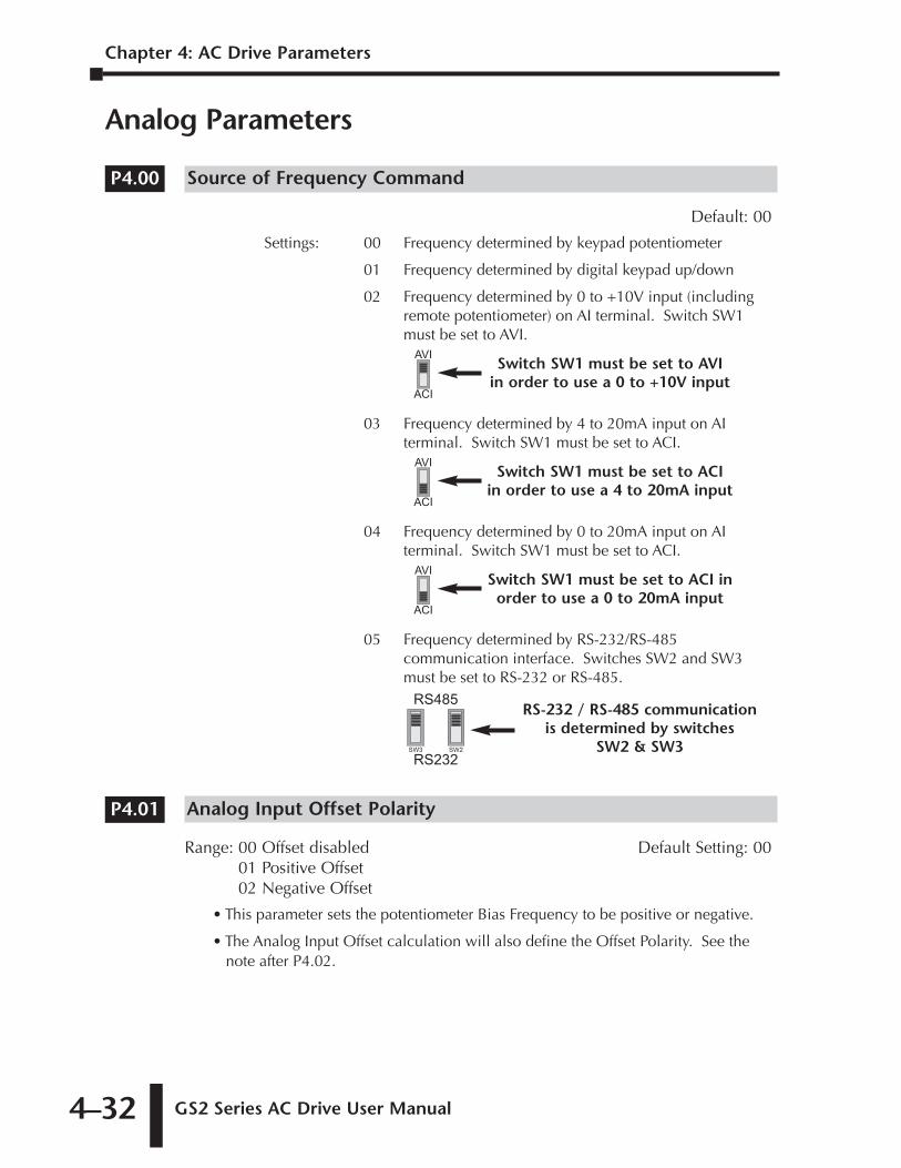
Chapter 4: AC Drive Parameters
GS2 Series AC Drive User Manual4–32
Analog Parameters
Source of Frequency Command
Default: 00
Settings: 00 Frequency determined by keypad potentiometer
01 Frequency determined by digital keypad up/down
02 Frequency determined by 0 to +10V input (includingremote potentiometer) on AI terminal. Switch SW1must be set to AVI.
03 Frequency determined by 4 to 20mA input on AIterminal. Switch SW1 must be set to ACI.
04 Frequency determined by 0 to 20mA input on AIterminal. Switch SW1 must be set to ACI.
05 Frequency determined by RS-232/RS-485communication interface. Switches SW2 and SW3must be set to RS-232 or RS-485.
Analog Input Offset Polarity
Range: 00 Offset disabled Default Setting: 0001 Positive Offset02 Negative Offset
• This parameter sets the potentiometer Bias Frequency to be positive or negative.
• The Analog Input Offset calculation will also define the Offset Polarity. See thenote after P4.02.
P4.01
RS485
RS232SW3 SW2
RS-232 / RS-485 communicationis determined by switches
SW2 & SW3
AVI
ACI
Switch SW1 must be set to ACI inorder to use a 0 to 20mA input
AVI
ACI
Switch SW1 must be set to ACI in order to use a 4 to 20mA input
AVI
ACI
Switch SW1 must be set to AVI in order to use a 0 to +10V input
P4.00
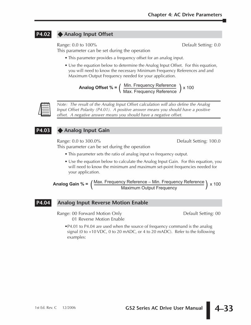
GS2 Series AC Drive User Manual 4–33
Chapter 4: AC Drive Parameters
1st Ed. Rev. C 12/2006
�� Analog Input Offset
Range: 0.0 to 100% Default Setting: 0.0This parameter can be set during the operation
• This parameter provides a frequency offset for an analog input.
• Use the equation below to determine the Analog Input Offset. For this equation,you will need to know the necessary Minimum Frequency References and andMaximum Output Frequency needed for your application.
�� Analog Input Gain
Range: 0.0 to 300.0% Default Setting: 100.0This parameter can be set during the operation
• This parameter sets the ratio of analog input vs frequency output.
• Use the equation below to calculate the Analog Input Gain. For this equation, youwill need to know the minimum and maximum set-point frequencies needed foryour application.
Analog Input Reverse Motion Enable
Range: 00 Forward Motion Only Default Setting: 0001 Reverse Motion Enable
•P4.01 to P4.04 are used when the source of frequency command is the analogsignal (0 to +10 VDC, 0 to 20 mADC, or 4 to 20 mADC). Refer to the followingexamples:
P4.04
Analog Gain % =Maximum Output Frequency
Max. Frequency Reference – Min. Frequency Reference( ) x 100
P4.03
Note: The result of the Analog Input Offset calculation will also define the AnalogInput Offset Polarity (P4.01). A positive answer means you should have a positiveoffset. A negative answer means you should have a negative offset.
x 100 Analog Offset % = Min. Frequency ReferenceMax. Frequency Reference ( )
P4.02
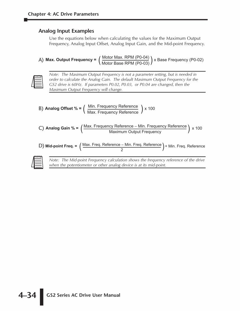
Chapter 4: AC Drive Parameters
GS2 Series AC Drive User Manual4–34
Analog Input ExamplesUse the equations below when calculating the values for the Maximum OutputFrequency, Analog Input Offset, Analog Input Gain, and the Mid-point Frequency.
A)
B)
C)
D)
Note: The Mid-point Frequency calculation shows the frequency reference of the drivewhen the potentiometer or other analog device is at its mid-point.
+ Min. Freq. ReferenceMid-point Freq. =2
Max. Freq. Reference – Min. Freq. Reference( )
Analog Gain % =Maximum Output Frequency
Max. Frequency Reference – Min. Frequency Reference( ) x 100
x 100 Analog Offset % = Min. Frequency ReferenceMax. Frequency Reference ( )
Note: The Maximum Output Frequency is not a parameter setting, but is needed inorder to calculate the Analog Gain. The default Maximum Output Frequency for theGS2 drive is 60Hz. If parameters P0.02, P0.03, or P0.04 are changed, then theMaximum Output Frequency will change.
x Base Frequency (P0-02)Max. Output Frequency = Motor Max. RPM (P0-04)Motor Base RPM (P0-03)( )
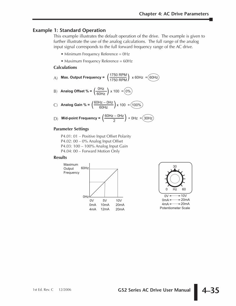
GS2 Series AC Drive User Manual 4–35
Chapter 4: AC Drive Parameters
1st Ed. Rev. C 12/2006
Example 1: Standard OperationThis example illustrates the default operation of the drive. The example is given tofurther illustrate the use of the analog calculations. The full range of the analoginput signal corresponds to the full forward frequency range of the AC drive.
• Minimum Frequency Reference = 0Hz
• Maximum Frequency Reference = 60Hz
Calculations
A)
B)
C)
D)
Parameter Settings
P4.01: 01 – Positive Input Offset PolarityP4.02: 00 – 0% Analog Input OffsetP4.03: 100 – 100% Analog Input GainP4.04: 00 – Forward Motion Only
Results
0 60Hz
30
Potentiometer Scale
0V 10V
4mA 20mA20mA
10V0Hz
0V
4mA
5V
12mA
60HzMaximumOutputFrequency
0mA 10mA 20mA 0mA 20mA
+ 0Hz = 30HzMid-point Frequency =2
60Hz – 0Hz( )
Analog Gain % =60Hz
60Hz – 0Hz( ) x 100 = 100%
x 100 = 0% Analog Offset % = 0Hz60Hz( )
x 60Hz = 60HzMax. Output Frequency = 1750 RPM1750 RPM( )
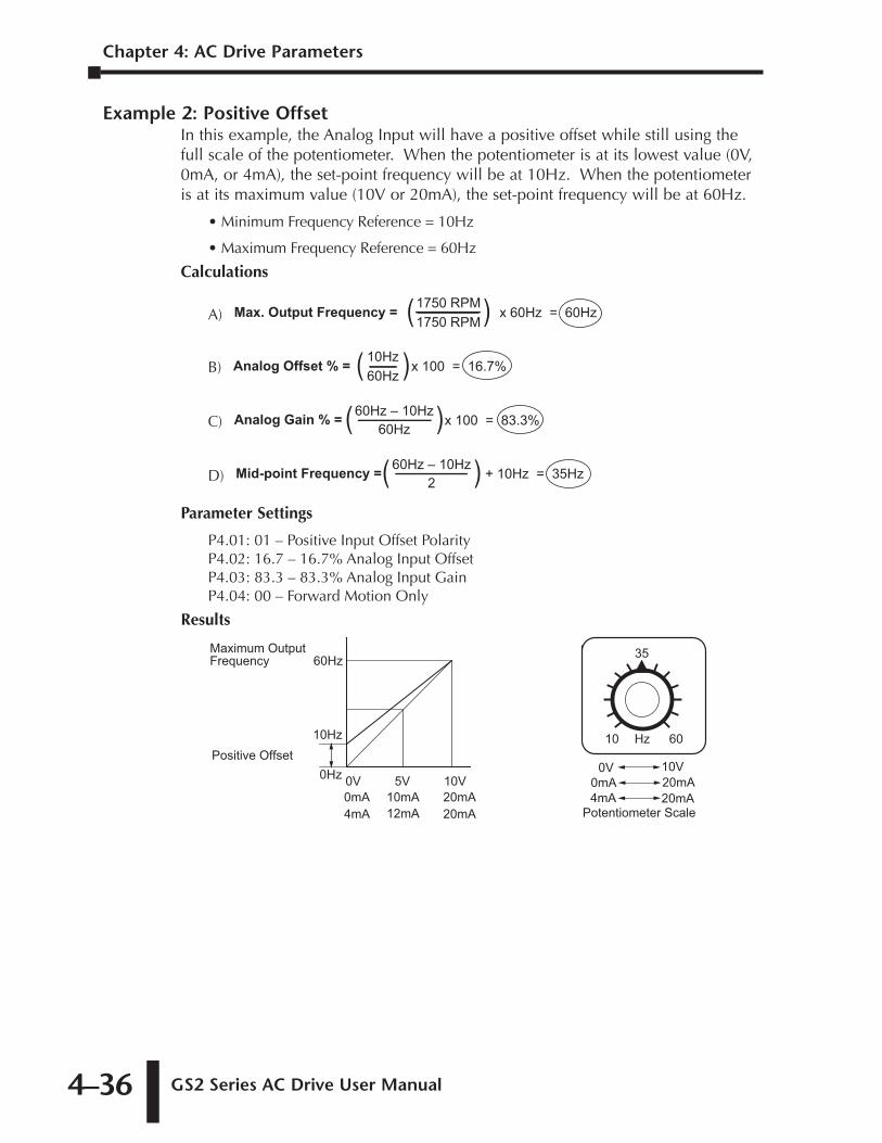
Chapter 4: AC Drive Parameters
GS2 Series AC Drive User Manual4–36
Example 2: Positive OffsetIn this example, the Analog Input will have a positive offset while still using thefull scale of the potentiometer. When the potentiometer is at its lowest value (0V,0mA, or 4mA), the set-point frequency will be at 10Hz. When the potentiometeris at its maximum value (10V or 20mA), the set-point frequency will be at 60Hz.
• Minimum Frequency Reference = 10Hz
• Maximum Frequency Reference = 60Hz
Calculations
A)
B)
C)
D)
Parameter Settings
P4.01: 01 – Positive Input Offset PolarityP4.02: 16.7 – 16.7% Analog Input OffsetP4.03: 83.3 – 83.3% Analog Input GainP4.04: 00 – Forward Motion Only
Results
10 60Hz
3560Hz
0Hz
10Hz
Maximum Output Frequency
Positive Offset
20mA
10V0V
4mA
5V
12mA0mA 10mA 20mA
Potentiometer Scale
0V 10V
4mA 20mA0mA 20mA
Mid-point Frequency =2
60Hz – 10Hz( ) + 10Hz = 35Hz
Analog Gain % =60Hz
60Hz – 10Hz( )x 100 = 83.3%
Analog Offset % = 10Hz60Hz( )x 100 = 16.7%
x 60Hz = 60HzMax. Output Frequency = 1750 RPM1750 RPM( )
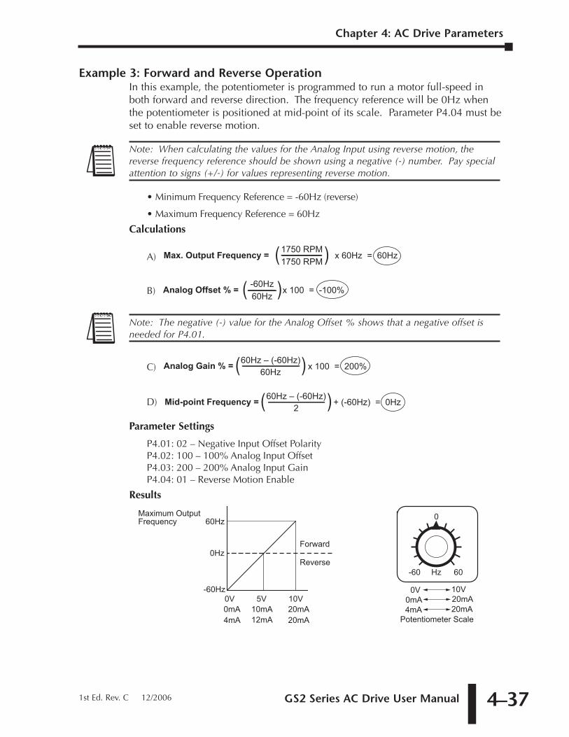
GS2 Series AC Drive User Manual 4–37
Chapter 4: AC Drive Parameters
1st Ed. Rev. C 12/2006
Example 3: Forward and Reverse OperationIn this example, the potentiometer is programmed to run a motor full-speed inboth forward and reverse direction. The frequency reference will be 0Hz whenthe potentiometer is positioned at mid-point of its scale. Parameter P4.04 must beset to enable reverse motion.
• Minimum Frequency Reference = -60Hz (reverse)
• Maximum Frequency Reference = 60Hz
Calculations
A)
B)
C)
D)
Parameter Settings
P4.01: 02 – Negative Input Offset PolarityP4.02: 100 – 100% Analog Input OffsetP4.03: 200 – 200% Analog Input GainP4.04: 01 – Reverse Motion Enable
Results
-60 60Hz
060Hz
-60Hz
Maximum Output Frequency
0HzForward
Reverse
Potentiometer Scale
0V 10V
4mA 20mA0mA 20mA
20mA
10V0V
4mA
5V
12mA0mA 10mA 20mA
Mid-point Frequency =2
60Hz – (-60Hz)( ) + (-60Hz) = 0Hz
Analog Gain % =60Hz
60Hz – (-60Hz)( ) x 100 = 200%
Note: The negative (-) value for the Analog Offset % shows that a negative offset isneeded for P4.01.
Analog Offset % = -60Hz60Hz( )x 100 = -100%
x 60Hz = 60HzMax. Output Frequency = 1750 RPM1750 RPM( )
Note: When calculating the values for the Analog Input using reverse motion, thereverse frequency reference should be shown using a negative (-) number. Pay specialattention to signs (+/-) for values representing reverse motion.
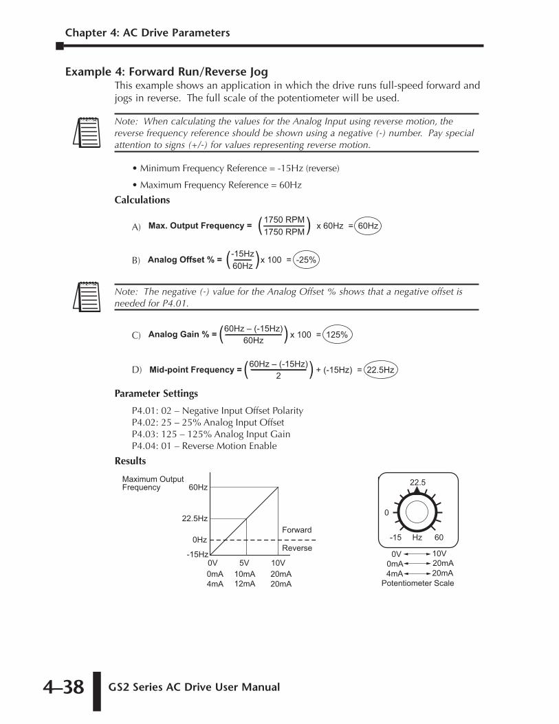
Chapter 4: AC Drive Parameters
GS2 Series AC Drive User Manual4–38
Example 4: Forward Run/Reverse JogThis example shows an application in which the drive runs full-speed forward andjogs in reverse. The full scale of the potentiometer will be used.
• Minimum Frequency Reference = -15Hz (reverse)
• Maximum Frequency Reference = 60Hz
Calculations
A)
B)
C)
D)
Parameter Settings
P4.01: 02 – Negative Input Offset PolarityP4.02: 25 – 25% Analog Input OffsetP4.03: 125 – 125% Analog Input GainP4.04: 01 – Reverse Motion Enable
Results
-15 60Hz
22.560Hz
-15Hz
Maximum Output Frequency
Forward
Reverse
22.5Hz
0Hz
0
20mA
10V0V
4mA
5V
12mA0mA 10mA 20mA
Potentiometer Scale
0V 10V
4mA 20mA0mA 20mA
Mid-point Frequency =2
60Hz – (-15Hz)( ) + (-15Hz) = 22.5Hz
Analog Gain % =60Hz
60Hz – (-15Hz)( ) x 100 = 125%
Note: The negative (-) value for the Analog Offset % shows that a negative offset isneeded for P4.01.
Analog Offset % = -15Hz60Hz( )x 100 = -25%
x 60Hz = 60HzMax. Output Frequency = 1750 RPM1750 RPM( )
Note: When calculating the values for the Analog Input using reverse motion, thereverse frequency reference should be shown using a negative (-) number. Pay specialattention to signs (+/-) for values representing reverse motion.
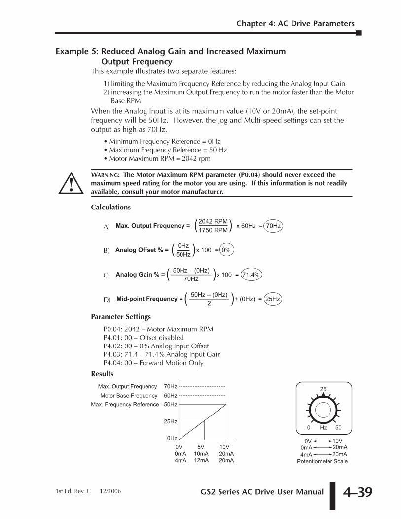
GS2 Series AC Drive User Manual 4–39
Example 5: Reduced Analog Gain and Increased Maximum Output Frequency
This example illustrates two separate features:
1) limiting the Maximum Frequency Reference by reducing the Analog Input Gain2) increasing the Maximum Output Frequency to run the motor faster than the Motor
Base RPM
When the Analog Input is at its maximum value (10V or 20mA), the set-pointfrequency will be 50Hz. However, the Jog and Multi-speed settings can set theoutput as high as 70Hz.
• Minimum Frequency Reference = 0Hz• Maximum Frequency Reference = 50 Hz• Motor Maximum RPM = 2042 rpm
Calculations
A)
B)
C)
D)
Parameter Settings
P0.04: 2042 – Motor Maximum RPMP4.01: 00 – Offset disabledP4.02: 00 – 0% Analog Input OffsetP4.03: 71.4 – 71.4% Analog Input GainP4.04: 00 – Forward Motion Only
Results
0 50Hz
2560Hz
Max. Output Frequency
25Hz
0Hz
50Hz
70HzMotor Base Frequency
Max. Frequency Reference
Potentiometer Scale
0V 10V
4mA 20mA0mA 20mA
20mA
10V0V
4mA
5V
12mA0mA 10mA 20mA
Mid-point Frequency =2
50Hz – (0Hz)( )+ (0Hz) = 25Hz
Analog Gain % =70Hz
50Hz – (0Hz)( )x 100 = 71.4%
Analog Offset % = 0Hz50Hz( )x 100 = 0%
x 60Hz = 70HzMax. Output Frequency = 2042 RPM1750 RPM( )
WARNING: The Motor Maximum RPM parameter (P0.04) should never exceed themaximum speed rating for the motor you are using. If this information is not readilyavailable, consult your motor manufacturer.
Chapter 4: AC Drive Parameters
1st Ed. Rev. C 12/2006
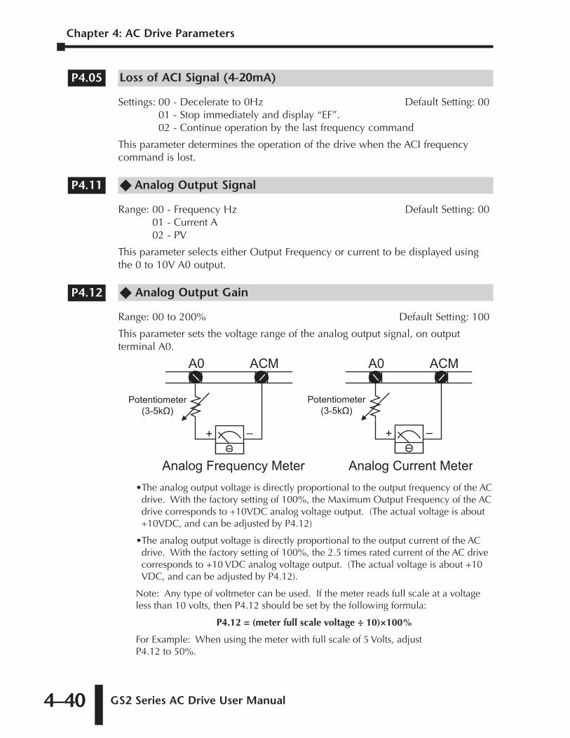
Chapter 4: AC Drive Parameters
GS2 Series AC Drive User Manual4–40
Loss of ACI Signal (4-20mA)
Settings: 00 - Decelerate to 0Hz Default Setting: 0001 - Stop immediately and display “EF”.02 - Continue operation by the last frequency command
This parameter determines the operation of the drive when the ACI frequencycommand is lost.
�� Analog Output Signal
Range: 00 - Frequency Hz Default Setting: 0001 - Current A02 - PV
This parameter selects either Output Frequency or current to be displayed usingthe 0 to 10V A0 output.
�� Analog Output Gain
Range: 00 to 200% Default Setting: 100
This parameter sets the voltage range of the analog output signal, on outputterminal A0.
•The analog output voltage is directly proportional to the output frequency of the ACdrive. With the factory setting of 100%, the Maximum Output Frequency of the ACdrive corresponds to +10VDC analog voltage output. (The actual voltage is about+10VDC, and can be adjusted by P4.12)
•The analog output voltage is directly proportional to the output current of the ACdrive. With the factory setting of 100%, the 2.5 times rated current of the AC drivecorresponds to +10 VDC analog voltage output. (The actual voltage is about +10VDC, and can be adjusted by P4.12).
Note: Any type of voltmeter can be used. If the meter reads full scale at a voltageless than 10 volts, then P4.12 should be set by the following formula:
P4.12 = (meter full scale voltage ÷ 10)×100%
For Example: When using the meter with full scale of 5 Volts, adjustP4.12 to 50%.
A0 ACM
Analog Frequency Meter
+ –
Potentiometer
(3-5k�)
A0 ACM
Analog Current Meter
+ –
Potentiometer
(3-5k�)
P4.12
P4.11
P4.05
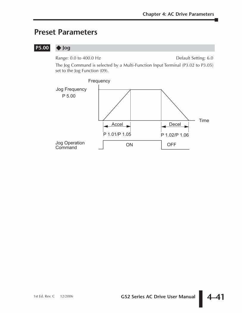
GS2 Series AC Drive User Manual 4–41
Chapter 4: AC Drive Parameters
1st Ed. Rev. C 12/2006
Preset Parameters
�� Jog
Range: 0.0 to 400.0 Hz Default Setting: 6.0
The Jog Command is selected by a Multi-Function Input Terminal (P3.02 to P3.05)set to the Jog Function (09).
Frequency
Time
Jog Frequency
DecelAccel
Jog OperationCommand ON OFF
P 1.02/P 1.06P 1.01/P 1.05
P 5.00
P5.00
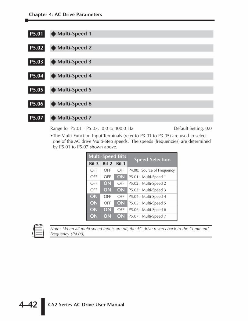
Chapter 4: AC Drive Parameters
GS2 Series AC Drive User Manual4–42
�� Multi-Speed 1
�� Multi-Speed 2
�� Multi-Speed 3
�� Multi-Speed 4
�� Multi-Speed 5
�� Multi-Speed 6
�� Multi-Speed 7
Range for P5.01 - P5.07: 0.0 to 400.0 Hz Default Setting: 0.0
•The Multi-Function Input Terminals (refer to P3.01 to P3.05) are used to selectone of the AC drive Multi-Step speeds. The speeds (frequencies) are determinedby P5.01 to P5.07 shown above.
Note: When all multi-speed inputs are off, the AC drive reverts back to the CommandFrequency (P4.00).
Multi-Speed BitsSpeed Selection
Bit 3 Bit 2 Bit 1OFF OFF OFF P4.00: Source of Frequency
OFF OFF ON P5.01: Multi-Speed 1
OFF ON OFF P5.02: Multi-Speed 2
OFF ON ON P5.03: Multi-Speed 3
ON OFF OFF P5.04: Multi-Speed 4
ON OFF ON P5.05: Multi-Speed 5
ON ON OFF P5.06: Multi-Speed 6
ON ON ON P5.07: Multi-Speed 7
P5.07
P5.06
P5.05
P5.04
P5.03
P5.02
P5.01
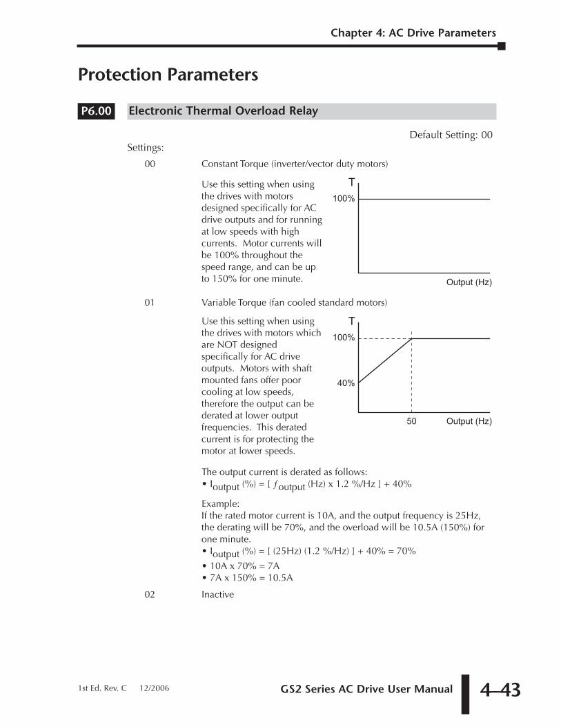
GS2 Series AC Drive User Manual 4–43
Protection Parameters
Electronic Thermal Overload Relay
Default Setting: 00Settings:
00 Constant Torque (inverter/vector duty motors)
01 Variable Torque (fan cooled standard motors)
The output current is derated as follows:• Ioutput (%) = [ ƒoutput (Hz) x 1.2 %/Hz ] + 40%
Example:If the rated motor current is 10A, and the output frequency is 25Hz,the derating will be 70%, and the overload will be 10.5A (150%) forone minute.• Ioutput (%) = [ (25Hz) (1.2 %/Hz) ] + 40% = 70%
• 10A x 70% = 7A• 7A x 150% = 10.5A
02 Inactive
Output (Hz)50
100%
T
40%
Use this setting when usingthe drives with motors whichare NOT designedspecifically for AC driveoutputs. Motors with shaftmounted fans offer poorcooling at low speeds,therefore the output can bederated at lower outputfrequencies. This deratedcurrent is for protecting themotor at lower speeds.
Output (Hz)
100%
TUse this setting when usingthe drives with motorsdesigned specifically for ACdrive outputs and for runningat low speeds with highcurrents. Motor currents willbe 100% throughout thespeed range, and can be upto 150% for one minute.
P6.00
Chapter 4: AC Drive Parameters
1st Ed. Rev. C 12/2006
Chapter 4: AC Drive Parameters
GS2 Series AC Drive User Manual4–44
Auto Restart After Fault
Range: 00 to 10 Default Setting: 00
• After fault occurs (allowable faults: over-current OC, over-voltage OV), the ACdrive can be reset/restarted automatically up to 10 times. Setting this parameter to0 will disable the reset/restart operation after any fault has occurred. Whenenabled, the AC drive will restart with speed search, which starts at the previousFrequency. To set the fault recovery time after a fault, please see (P6.13) base-block time for speed search.
Momentary Power Loss
Default Setting: 00
Settings: 00 Stop operation after momentary power loss.
01 Continue operation after momentary powerloss, speed search from Speed Reference.
02 Continue operation after momentary powerloss, speed search from Minimum Speed.
Reverse Operation Inhibit
Default Setting: 00
Settings: 00 Enable Reverse Operation
01 Disable Reverse Operation
This parameter determines whether the AC Motor Drive can operate in the reversedirection.
P6.03
Note: Also refer to P6.30, Line Start Lockout.Note: This parameter (P6.02) will work only if the Source of Operation (P3.00) is set
to something other than 00 (Operation determined by digital keypad).
P6.02
P6.01
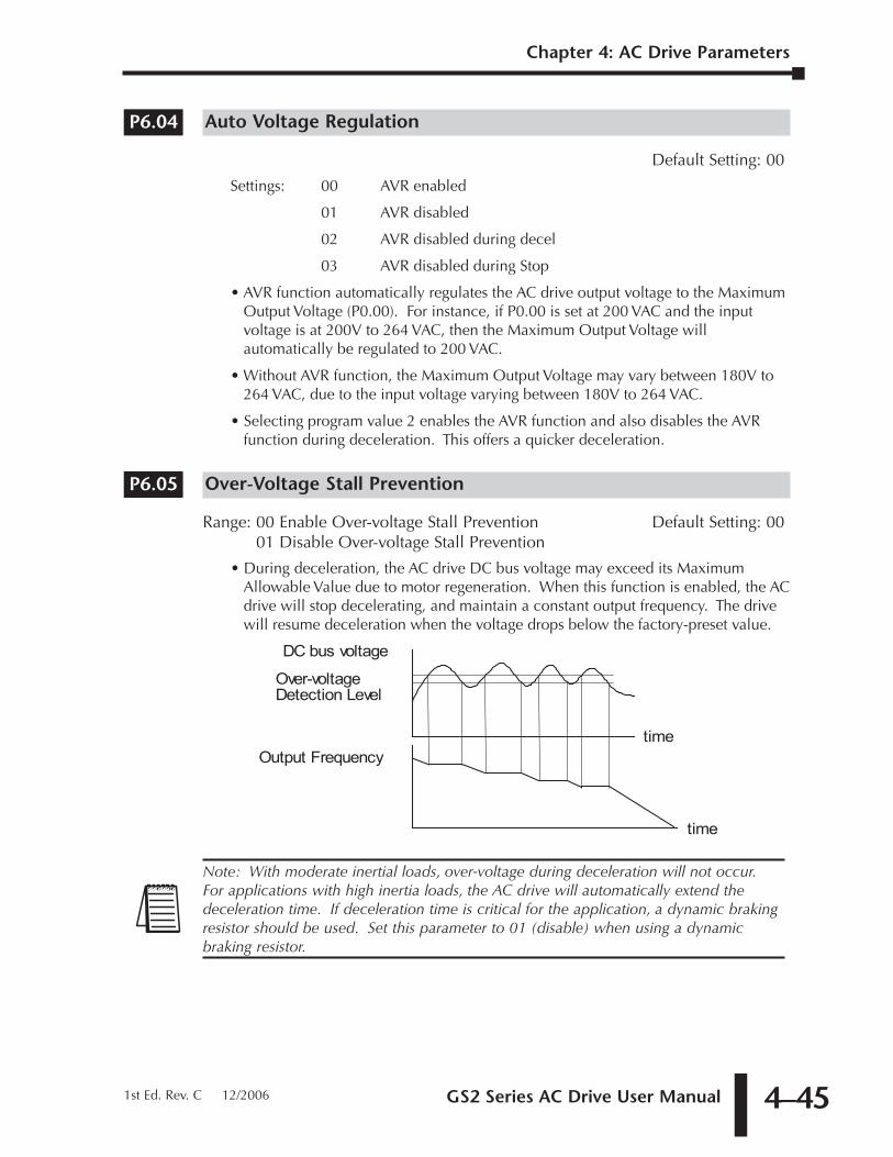
GS2 Series AC Drive User Manual 4–45
Chapter 4: AC Drive Parameters
1st Ed. Rev. C 12/2006
Auto Voltage Regulation
Default Setting: 00
Settings: 00 AVR enabled
01 AVR disabled
02 AVR disabled during decel
03 AVR disabled during Stop
• AVR function automatically regulates the AC drive output voltage to the MaximumOutput Voltage (P0.00). For instance, if P0.00 is set at 200 VAC and the inputvoltage is at 200V to 264 VAC, then the Maximum Output Voltage willautomatically be regulated to 200 VAC.
• Without AVR function, the Maximum Output Voltage may vary between 180V to264 VAC, due to the input voltage varying between 180V to 264 VAC.
• Selecting program value 2 enables the AVR function and also disables the AVRfunction during deceleration. This offers a quicker deceleration.
Over-Voltage Stall Prevention
Range: 00 Enable Over-voltage Stall Prevention Default Setting: 0001 Disable Over-voltage Stall Prevention
• During deceleration, the AC drive DC bus voltage may exceed its MaximumAllowable Value due to motor regeneration. When this function is enabled, the ACdrive will stop decelerating, and maintain a constant output frequency. The drivewill resume deceleration when the voltage drops below the factory-preset value.
Note: With moderate inertial loads, over-voltage during deceleration will not occur.For applications with high inertia loads, the AC drive will automatically extend thedeceleration time. If deceleration time is critical for the application, a dynamic brakingresistor should be used. Set this parameter to 01 (disable) when using a dynamicbraking resistor.
DC bus voltage
Over-voltage
Detection Level
Output Frequency
time
time
P6.05
P6.04
Chapter 4: AC Drive Parameters
GS2 Series AC Drive User Manual4–46
Auto Adjustable Accel/Decel
Default Setting: 00
Settings: 00 Linear Accel/Decel
01 Auto Accel, Linear Decel
02 Linear Accel, Auto Decel
03 Auto Accel/Decel
04 Auto Accel/Decel Stall Prevention
If the auto accel/decel is selected, the AC drive will accel/decel in the fastest andsmoothest means possible by automatically adjusting the time of accel/decel.
This parameter provides five modes to choose:
• 00 Linear Acceleration and deceleration (operation by P1.01,P1.02 or P1.05, P1.06 acceleration/deceleration time).
• 01 Automatic acceleration, linear deceleration (Operation by automaticacceleration time, P1.02 or P1.06 deceleration time).
• 02 Linear acceleration and automatic deceleration (Operation by automaticacceleration time, P1.01 or P1.05 acceleration time).
• 03 Automatic acceleration, deceleration (Operation by AC drive auto adjustablecontrol).
• 04 Auto acceleration, deceleration. The auto accel/decel will not be quicker thanthe settings for acceleration (P1.01 or P1.05) or deceleration (P1.02 or P1.06).The operation is specific to preventing a stall.
Over-Torque Detection Mode
Default Setting: 00
Settings: 00 Disabled
01 Enabled during constant speed operation
02 Enabled during acceleration
Over-Torque Detection Level
Range: 30 to 200% Default Setting: 150
• A setting of 100% is proportional to the Rated Output Current of the drive.
• This parameter sets the Over-Torque Detection level in 1% increments. (The ACdrive rated current is equal to 100%.)
Over-Torque Detection Time
Range: 0.1 to 10.0 Default Setting: 0.1
This parameter sets the Over-Torque Detection Time in units of 0.1 seconds.
P6.09
P6.08
P6.07
P6.06
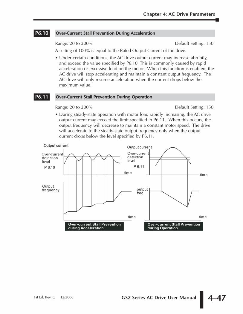
GS2 Series AC Drive User Manual 4–47
Chapter 4: AC Drive Parameters
1st Ed. Rev. C 12/2006
Over-Current Stall Prevention During Acceleration
Range: 20 to 200% Default Setting: 150
A setting of 100% is equal to the Rated Output Current of the drive.
• Under certain conditions, the AC drive output current may increase abruptly,and exceed the value specified by P6.10 This is commonly caused by rapidacceleration or excessive load on the motor. When this function is enabled, theAC drive will stop accelerating and maintain a constant output frequency. TheAC drive will only resume acceleration when the current drops below themaximum value.
Over-Current Stall Prevention During Operation
Range: 20 to 200% Default Setting: 150
• During steady-state operation with motor load rapidly increasing, the AC driveoutput current may exceed the limit specified in P6.11. When this occurs, theoutput frequency will decrease to maintain a constant motor speed. The drivewill accelerate to the steady-state output frequency only when the outputcurrent drops below the level specified by P6.11.
Output current
Over-current
detection
level
Output current
time
Output
frequency output
freq
time
Over-current Stall Prevention
during Operation
time
P 6.10
time
Over-current
detection
level
P 6.11
Over-current Stall Prevention
during Acceleration
P6.11
P6.10
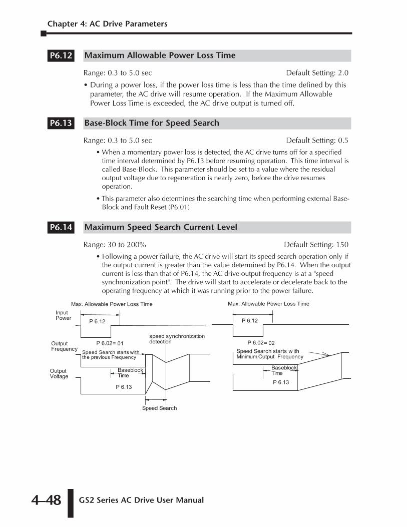
Chapter 4: AC Drive Parameters
GS2 Series AC Drive User Manual4–48
Maximum Allowable Power Loss Time
Range: 0.3 to 5.0 sec Default Setting: 2.0
• During a power loss, if the power loss time is less than the time defined by thisparameter, the AC drive will resume operation. If the Maximum AllowablePower Loss Time is exceeded, the AC drive output is turned off.
Base-Block Time for Speed Search
Range: 0.3 to 5.0 sec Default Setting: 0.5
• When a momentary power loss is detected, the AC drive turns off for a specifiedtime interval determined by P6.13 before resuming operation. This time interval iscalled Base-Block. This parameter should be set to a value where the residualoutput voltage due to regeneration is nearly zero, before the drive resumesoperation.
• This parameter also determines the searching time when performing external Base-Block and Fault Reset (P6.01)
Maximum Speed Search Current Level
Range: 30 to 200% Default Setting: 150
• Following a power failure, the AC drive will start its speed search operation only ifthe output current is greater than the value determined by P6.14. When the outputcurrent is less than that of P6.14, the AC drive output frequency is at a "speedsynchronization point". The drive will start to accelerate or decelerate back to theoperating frequency at which it was running prior to the power failure.
Input
Power
Output
Frequency
Output
Voltage
Speed Search starts with
the previous Frequency
Max. Allowable Power Loss Time
Speed Search
speed synchronization
detection
Baseblock
Time
= 01
P 6.12
P 6.02
P 6.13
= 02
Speed Search starts w ith
Minimum Output Frequency
Baseblock
Time
Max. Allowable Power Loss Time
P 6.12
P 6.02
P 6.13
P6.14
P6.13
P6.12
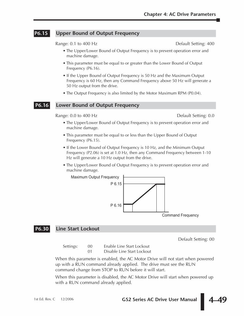
GS2 Series AC Drive User Manual 4–49
Chapter 4: AC Drive Parameters
1st Ed. Rev. C 12/2006
Upper Bound of Output Frequency
Range: 0.1 to 400 Hz Default Setting: 400
• The Upper/Lower Bound of Output Frequency is to prevent operation error andmachine damage.
• This parameter must be equal to or greater than the Lower Bound of OutputFrequency (P6.16).
• If the Upper Bound of Output Frequency is 50 Hz and the Maximum OutputFrequency is 60 Hz, then any Command Frequency above 50 Hz will generate a50 Hz output from the drive.
• The Output Frequency is also limited by the Motor Maximum RPM (P0.04).
Lower Bound of Output Frequency
Range: 0.0 to 400 Hz Default Setting: 0.0
• The Upper/Lower Bound of Output Frequency is to prevent operation error andmachine damage.
• This parameter must be equal to or less than the Upper Bound of OutputFrequency (P6.15).
• If the Lower Bound of Output Frequency is 10 Hz, and the Minimum OutputFrequency (P2.06) is set at 1.0 Hz, then any Command Frequency between 1-10Hz will generate a 10 Hz output from the drive.
• The Upper/Lower Bound of Output Frequency is to prevent operation error andmachine damage.
Line Start Lockout
Default Setting: 00
Settings: 00 Enable Line Start Lockout01 Disable Line Start Lockout
When this parameter is enabled, the AC Motor Drive will not start when poweredup with a RUN command already applied. The drive must see the RUNcommand change from STOP to RUN before it will start.
When this parameter is disabled, the AC Motor Drive will start when powered upwith a RUN command already applied.
P6.30
Command Frequency
Maximum Output FrequencyP 6.15
P 6.16
P6.16
P6.15
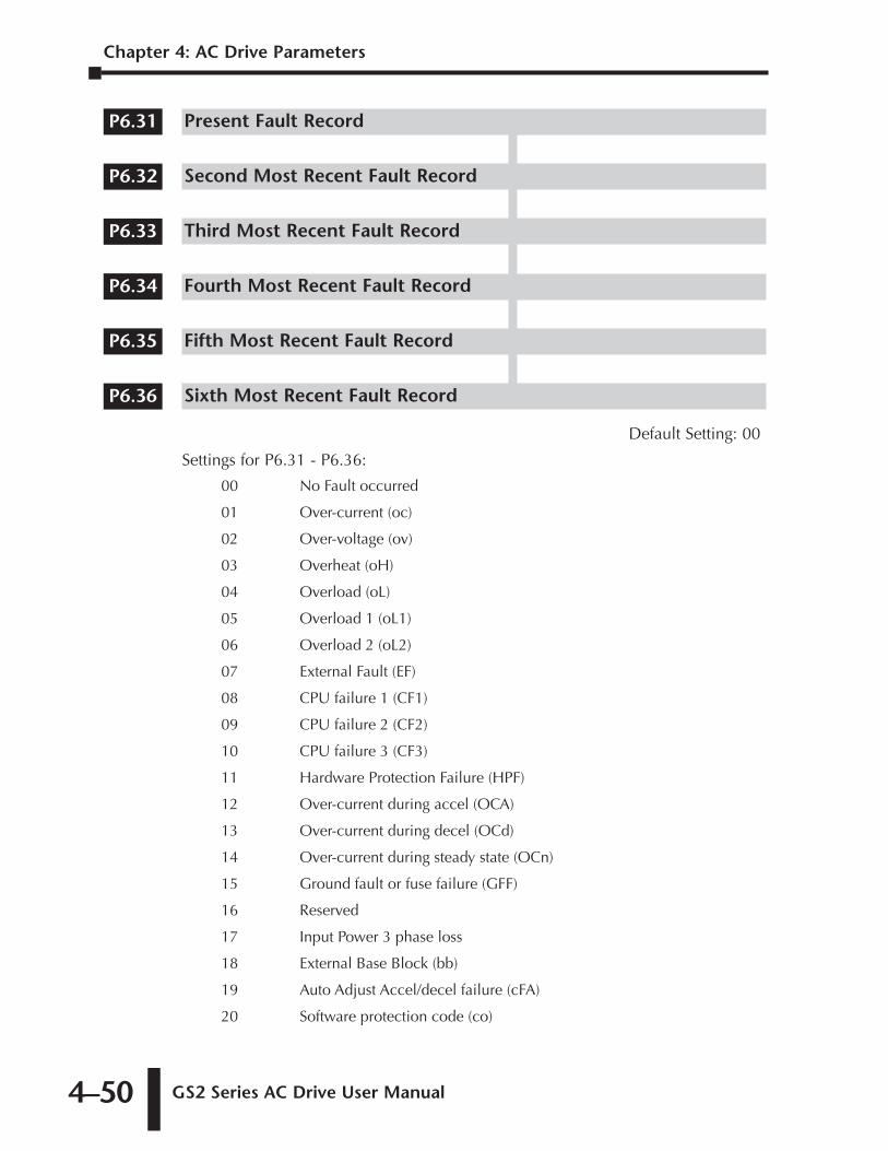
Chapter 4: AC Drive Parameters
GS2 Series AC Drive User Manual4–50
Present Fault Record
Second Most Recent Fault Record
Third Most Recent Fault Record
Fourth Most Recent Fault Record
Fifth Most Recent Fault Record
Sixth Most Recent Fault Record
Default Setting: 00
Settings for P6.31 - P6.36:
00 No Fault occurred
01 Over-current (oc)
02 Over-voltage (ov)
03 Overheat (oH)
04 Overload (oL)
05 Overload 1 (oL1)
06 Overload 2 (oL2)
07 External Fault (EF)
08 CPU failure 1 (CF1)
09 CPU failure 2 (CF2)
10 CPU failure 3 (CF3)
11 Hardware Protection Failure (HPF)
12 Over-current during accel (OCA)
13 Over-current during decel (OCd)
14 Over-current during steady state (OCn)
15 Ground fault or fuse failure (GFF)
16 Reserved
17 Input Power 3 phase loss
18 External Base Block (bb)
19 Auto Adjust Accel/decel failure (cFA)
20 Software protection code (co)
P6.36
P6.35
P6.34
P6.33
P6.32
P6.31
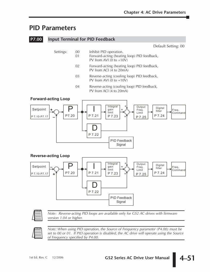
GS2 Series AC Drive User Manual 4–51
Chapter 4: AC Drive Parameters
1st Ed. Rev. C 12/2006
PID Parameters
Input Terminal for PID Feedback
Default Setting: 00Settings: 00 Inhibit PID operation.
01 Forward-acting (heating loop) PID feedback,PV from AVI (0 to +10V)
02 Forward-acting (heating loop) PID feedback,PV from ACI (4 to 20mA)
03 Reverse-acting (cooling loop) PID feedback,PV from AVI (0 to +10V)
04 Reverse-acting (cooling loop) PID feedback,PV from ACI (4 to 20mA)
Note: When using PID operation, the Source of Frequency parameter (P4.00) must beset to 00 or 01. If PID operation is disabled, the AC drive will operate using the Sourceof Frequency specified by P4.00.
Note: Reverse-acting PID loops are available only for GS2 AC drives with firmwareversion 1.04 or higher.
PP7.20
IP 7.21
DP 7.22
P 7.23 P 7.25P 7.24
–
+
+
+Setpoint
PID Feedback
Signal
Integral
gain
limit
Output
Freq.
Limit
Digital
filterFreq.
Command
P 7.10-P7.17 +
Reverse-acting Loop
PP7.20
IP 7.21
DP 7.22
P 7.23 P 7.25P 7.24
+
+
+
+Setpoint
PID Feedback
Signal
Integral
gain
limit
Output
Freq.
Limit
Digital
filterFreq.
Command
P 7.10-P7.17 –
Forward-acting Loop
P7.00
Chapter 4: AC Drive Parameters
GS2 Series AC Drive User Manual4–52
PV 100% Value
Range: 0.0 to 999 Default Setting: 100.0This parameter should be set to the value corresponding to the 100% value of the processvariable (PV). The setting for P7.01 cannot be less than any setting for P7.10 to P7.17.
PID Setpoint Source
Settings: 00 - Keypad Default Setting: 0001 - Serial Communications
�� Keypad PID Setpoint
Range: 0.0 to 999 Default Setting: 0.0
�� PID Multi-setpoint 1
Range: 0.0 to 999 Default Setting: 0.0
•The Multi-Function Input Terminals DI3 to DI6 are used to select one of the PIDMulti-Setpoints. (For further explanation, refer to settings 03, 04, and 05 forP3.02 to P3.05.) The setpoints are determined by P7.11 to P7.17.
�� PID Multi-setpoint 2
Range: 0.0 to 999 Default Setting: 0.0
•Refer to P7.11 for explanation.
�� PID Multi-setpoint 3
Range: 0.0 to 999 Default Setting: 0.0
•Refer to P7.11 for explanation.
�� PID Multi-setpoint 4
Range: 0.0 to 999 Default Setting: 0.0
•Refer to P7.11 for explanation.
�� PID Multi-setpoint 5
Range: 0.0 to 999 Default Setting: 0.0
•Refer to P7.11 for explanation.
P7.15
P7.14
P7.13
P7.12
P7.11
Note: The settings for P7.10 to P7.17 cannot exceed the setting for P7.01.
P7.10
P7.02
Note: The setting for PV 100% value (P7.01) cannot be set less than any value set forP7.10 to P7.17. If you are unable to reduce P7.01 to the desired value, checkparameters P7.10 to P7.17 and reduce these values accordingly.
P7.01
GS2 Series AC Drive User Manual 4–53
Chapter 4: AC Drive Parameters
1st Ed. Rev. C 12/2006
�� PID Multi-setpoint 6
Range: 0.0 to 999 Default Setting: 0.0
•Refer to P7.11 for explanation.
�� PID Multi-setpoint 7
Range: 0.0 to 999 Default Setting: 0.0
•Refer to P7.11 for explanation.
�� Proportional Control (P)
Range: 0.0 to 10.0 Default Setting: 1.0The first parameter of PID control is Proportional Control (P). For a given process,if the Proportional Value is set too low, the control action will be too sluggish. Ifthe Proportional value is set too high, the control action will be unstable (erratic).
Set the Integral Control (I) and Derivative Control (D) to zero (0). Begin tuning theprocess with a low Proportional Value, and increase the Proportional value until thesystem goes unstable (erratic). When instability is reached, reduce the ProportionalValue slightly until the system becomes stable (smaller values reduce system Gain).Stability can be tested by moving between two wide-spread setpoint values.
With 10% deviation and P=1, then P X 10% = Control Output. For example, if thespeed of a motor is dragged down 10% due to a load increase, a corrective speedsignal increase of 10% is generated. In a perfect world, this increase in speedcommand should bring the motor speed back to normal.
�� Integral Control (I)
Range: 0.00 to 100.0 sec (0.00 disable) Default Setting: 1.00
Using only the Proportional Control, the corrective action may not increase fastenough or the setpoint may never be reached because of system losses. TheIntegral Control is used to generate additional corrective action.
When tuning, begin with a large Integral value and reduce the value until the systemgoes unstable (erratic). When instability is reached, increase the Integral value slightlyuntil the system becomes stable and the desired setpoint value is reached.
�� Derivative Control (D)
Range: 0.00 to 1.00 sec Default Setting: 0.00
If the control output is too sluggish after the Proportional Control (P) and IntegralControl (I) values are set, Derivative Control (D) may be required. Begin with ahigh Derivative value and reduce the value to the point of system instability. Thenincrease the Derivative value until the control output regains stability. Stability canbe tested by moving between two wide-spread setpoint values.
P7.22
P7.21
P7.20
P7.17
P7.16
Chapter 4: AC Drive Parameters
GS2 Series AC Drive User Manual4–54
Upper Bound for Integral Control
Range: 00 to 100% Default Setting: 100
• This parameter defines an upper boundary or limit for the integral gain (I) andtherefore limits the Master Frequency. Use the formula below to calculate theIntegral upper limit.
• The formula is: Integral upper limit = (Maximum Output Frequency) X P7.23. Thisparameter can limit the Maximum Output Frequency
Derivative Filter Time Constant
Range: 0.0 to 2.5 sec Default Setting: 0.0
• To avoid amplification of measured noise in the controller output, a derivativedigital filter is inserted. This filter helps smooth oscillations. Larger values for P7.24provide more smoothing.
PID Output Frequency Limit
Range: 00 to 110% Default Setting: 100
• This parameter defines the percentage of output frequency limit during the PID control.The formula is Output Frequency Limit = (Maximum Output Frequency) X P7.25. Thisparameter will limit the Maximum Output Frequency.
Feedback Signal Loss Detection Time
Range: 0.0 to 3600 sec Default Setting: 60
• This parameter defines how long the PID Feedback signal is lost before an error isgenerated. Setting this parameter to 0.0 disables the PID Feedback loss timer. When the feedback signal is lost, PID Feedback loss timer starts timing. When thetimer value is greater than the setting value of P. 7.26, the PID Feedback Lossparameter (P7.27) is activated. Furthermore, the Keypad will display "FbE" meansthe feedback abnormality detected. When the signal is corrected, the warningmessage "FbE" will automatically be cleared.
PID Feedback Loss Operation
Range: 00 - Warn and AC Drive Stop Default Setting: 0001 - Warn and Continue Operation
• This parameter sets the operation of the drive when there is a loss of the PIDfeedback signal.
• This parameter only functions with 4-20ma for feedback loss operation.
P7.27
P7.26
x Base Frequency (P0-02)Max. Output Frequency = Motor Max. RPM (P0-04)Motor Base RPM (P0-03)( )
P7.25
P7.24
x Base Frequency (P0-02)Max. Output Frequency = Motor Max. RPM (P0-04)Motor Base RPM (P0-03)( )
P7.23
GS2 Series AC Drive User Manual 4–55
Chapter 4: AC Drive Parameters
1st Ed. Rev. C 12/2006
Display Parameters
�� User Defined Display Function
Default Setting: 00
Settings: 00 Output Frequency (Hz)01 Motor Speed (RPM)02 Output Frequency x P8.0103 Output Current (A)04 Motor Output Current (%)05 Output Voltage(V)06 DC Bus Voltage (V)07 PID Setpoint08 PID Feedback (PV)09 Frequency Setpoint
�� Frequency Scale Factor
Range: 0.01 to 160.0 Default Setting: 1.0
This parameter can be used to multiply the display unit by a scaling factor so thatthe display will represent some other user desired unit. For example, the user maywant to scale the drive display to represent ft/min for a motor that is driving aconveyor.
The coefficient K determines the multiplying factor for the user-defined unit.
• The display value is calculated as follows:
Display value = output frequency x K
• The display window is only capable of showing four digits, butP8.01 can be used to create larger numbers. The display window uses decimalpoints to signify numbers up to five digits as explained below:
DISPLAY NUMBER REPRESENTED
9999 The absence of a decimal point indicates a four digit integer.
999.9 A single decimal point between the middle and the right-mostnumbers is a true decimal point; it separates ones and tenthsas in “300.5 (three hundred and one-half).
9999. A single decimal point after the right-most number is not atrue decimal point; instead it indicates that a zero follows theright-most numbers. For example, the number 12340 wouldbe displayed as “1234.”.
P8.01
P8.00
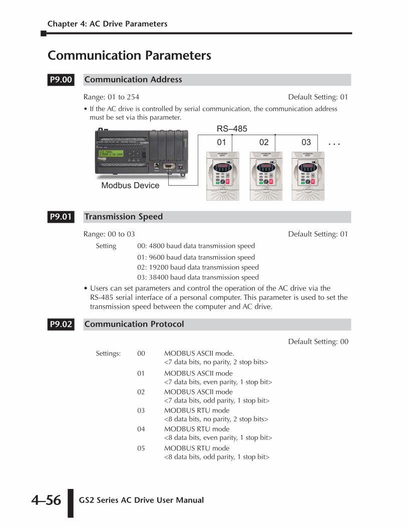
Chapter 4: AC Drive Parameters
GS2 Series AC Drive User Manual4–56
Communication Parameters
Communication Address
Range: 01 to 254 Default Setting: 01
• If the AC drive is controlled by serial communication, the communication addressmust be set via this parameter.
Transmission Speed
Range: 00 to 03 Default Setting: 01
Setting 00: 4800 baud data transmission speed
01: 9600 baud data transmission speed02: 19200 baud data transmission speed03: 38400 baud data transmission speed
• Users can set parameters and control the operation of the AC drive via the RS-485 serial interface of a personal computer. This parameter is used to set thetransmission speed between the computer and AC drive.
Communication Protocol
Default Setting: 00
Settings: 00 MODBUS ASCII mode.<7 data bits, no parity, 2 stop bits>
01 MODBUS ASCII mode<7 data bits, even parity, 1 stop bit>
02 MODBUS ASCII mode<7 data bits, odd parity, 1 stop bit>
03 MODBUS RTU mode<8 data bits, no parity, 2 stop bits>
04 MODBUS RTU mode<8 data bits, even parity, 1 stop bit>
05 MODBUS RTU mode<8 data bits, odd parity, 1 stop bit>
P9.02
P9.01
01 02 03 . . .RS–485
Modbus Device
P9.00
GS2 Series AC Drive User Manual 4–57
Chapter 4: AC Drive Parameters
1st Ed. Rev. C 12/2006
Transmission Fault Treatment
Default Setting: 00
Settings: 00 - Display fault and continue operating
01 - Display fault and RAMP to stop
02 - Display fault and COAST to stop
03 - No fault displayed and continue operating
Time Out Detection
Range: 00 - Disable Default Setting: 0001 - Enable
•This parameter is used for ASCII mode. When this parameter is set to01, it indicates that the over-time detection is enabled and the time slot betweeneach character cannot exceed 500 ms.
Time Out Duration
Range: 0.1 to 60.0 seconds Default Setting: 0.5
�� Parameter Lock
Default Setting: 00
Settings: 00 All parameters can be set and read01 All parameters are read only
Restore to Default
Settings: 0 or 99 Default Setting: 00•• Setting 99 restores all parameters to factory defaults. ••
P9.08
P9.07
P9.05
P9.04
P9.03
Chapter 4: AC Drive Parameters
GS2 Series AC Drive User Manual4–58
�� Block Transfer Parameter 1
Range: P0.00 to P8.01, P9.99 Default Setting: P9.99The sequential block transfer parameters (P9.11 through P9.25) allow you to"group" various miscellaneous non-sequential parameters, so that only one PLCprogramming write instruction is required to update those parameters, instead ofthree separate write instructions.
• Example:Writing directly to three non-sequential parameters P1.00, P1.02, and P1.04requires three separate write instructions from the PLC. However, those driveparameters can be updated with only one PLC write instruction to the sequentialtransfer blocks P9.11 through P9.13; if P9.11 is set to P1.00, P9.12 is set to P1.02,and P9.13 is set to P1.04.
�� Block Transfer Parameter 2
Range: P0.00 to P8.01, P9.99 Default Setting: P9.99
�� Block Transfer Parameter 3
Range: P0.00 to P8.01, P9.99 Default Setting: P9.99
�� Block Transfer Parameter 4
Range: P0.00 to P8.01, P9.99 Default Setting: P9.99
�� Block Transfer Parameter 5
Range: P0.00 to P8.01, P9.99 Default Setting: P9.99
�� Block Transfer Parameter 6
Range: P0.00 to P8.01, P9.99 Default Setting: P9.99
�� Block Transfer Parameter 7
Range: P0.00 to P8.01, P9.99 Default Setting: P9.99
�� Block Transfer Parameter 8
Range: P0.00 to P8.01, P9.99 Default Setting: P9.99
�� Block Transfer Parameter 9
Range: P0.00 to P8.01, P9.99 Default Setting: P9.99
P9.19
P9.18
P9.17
P9.16
P9.15
P9.14
P9.13
P9.12
P9.11
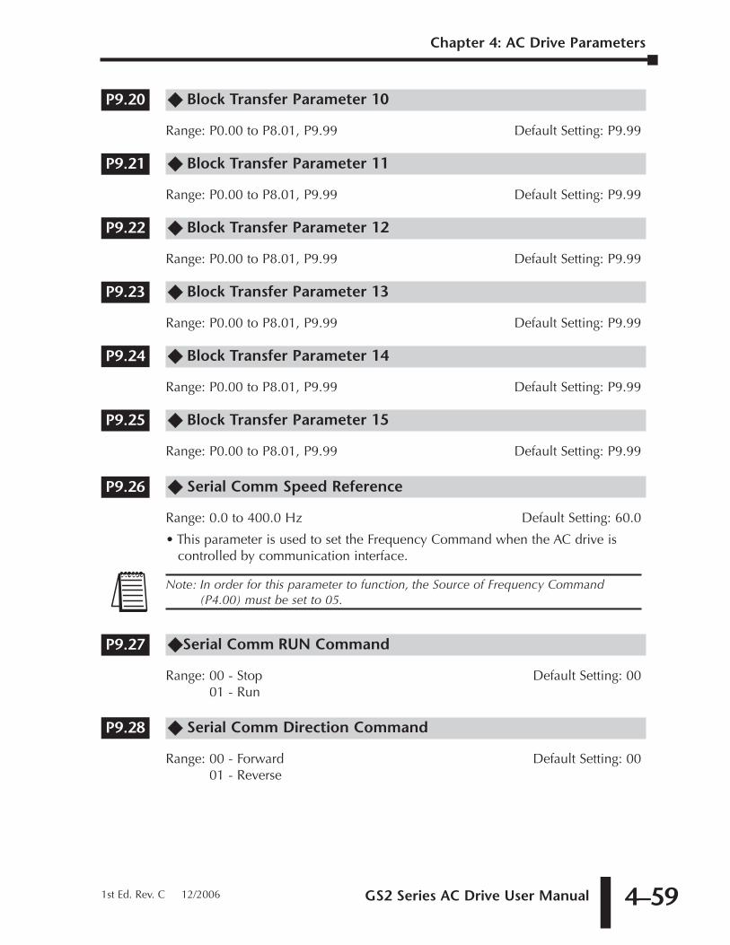
GS2 Series AC Drive User Manual 4–59
Chapter 4: AC Drive Parameters
1st Ed. Rev. C 12/2006
�� Block Transfer Parameter 10
Range: P0.00 to P8.01, P9.99 Default Setting: P9.99
�� Block Transfer Parameter 11
Range: P0.00 to P8.01, P9.99 Default Setting: P9.99
�� Block Transfer Parameter 12
Range: P0.00 to P8.01, P9.99 Default Setting: P9.99
�� Block Transfer Parameter 13
Range: P0.00 to P8.01, P9.99 Default Setting: P9.99
�� Block Transfer Parameter 14
Range: P0.00 to P8.01, P9.99 Default Setting: P9.99
�� Block Transfer Parameter 15
Range: P0.00 to P8.01, P9.99 Default Setting: P9.99
�� Serial Comm Speed Reference
Range: 0.0 to 400.0 Hz Default Setting: 60.0
• This parameter is used to set the Frequency Command when the AC drive iscontrolled by communication interface.
��Serial Comm RUN Command
Range: 00 - Stop Default Setting: 0001 - Run
�� Serial Comm Direction Command
Range: 00 - Forward Default Setting: 0001 - Reverse
P9.28
P9.27
Note: In order for this parameter to function, the Source of Frequency Command(P4.00) must be set to 05.
P9.26
P9.25
P9.24
P9.23
P9.22
P9.21
P9.20
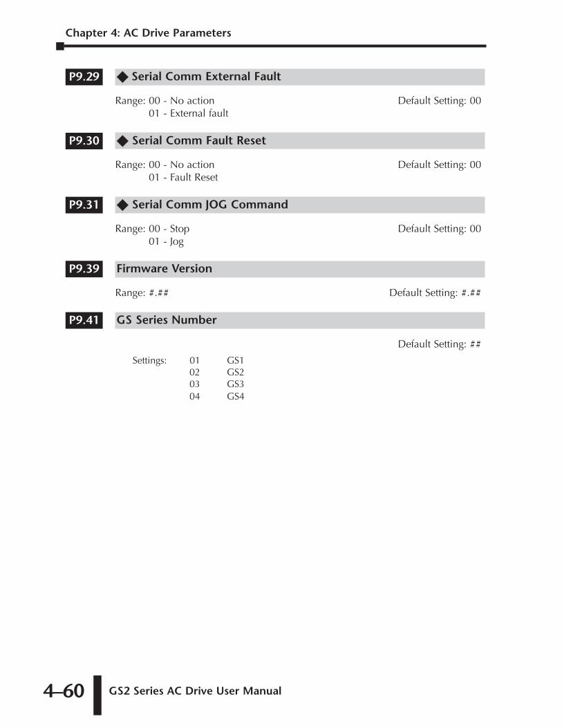
Chapter 4: AC Drive Parameters
GS2 Series AC Drive User Manual4–60
�� Serial Comm External Fault
Range: 00 - No action Default Setting: 0001 - External fault
�� Serial Comm Fault Reset
Range: 00 - No action Default Setting: 0001 - Fault Reset
�� Serial Comm JOG Command
Range: 00 - Stop Default Setting: 0001 - Jog
Firmware Version
Range: #.## Default Setting: #.##
GS Series Number
Default Setting: ##
Settings: 01 GS1 02 GS203 GS304 GS4
P9.41
P9.39
P9.31
P9.30
P9.29
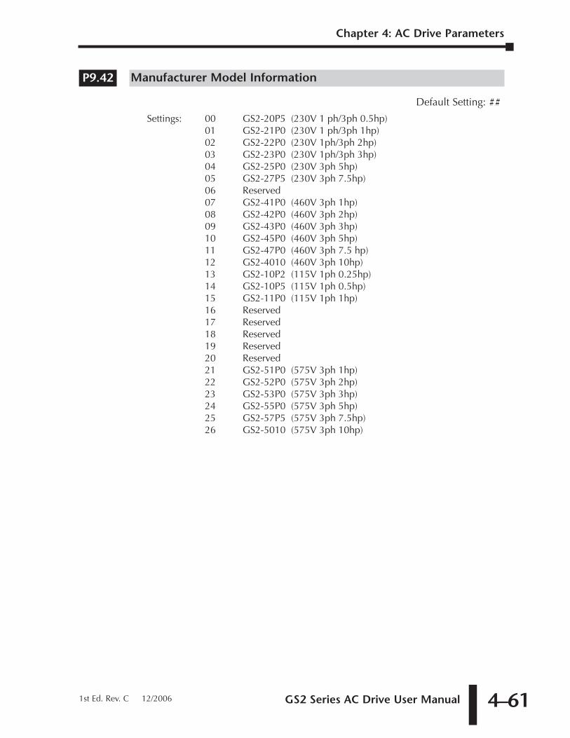
GS2 Series AC Drive User Manual 4–61
Manufacturer Model Information
Default Setting: ##
Settings: 00 GS2-20P5 (230V 1 ph/3ph 0.5hp)01 GS2-21P0 (230V 1 ph/3ph 1hp)02 GS2-22P0 (230V 1ph/3ph 2hp)03 GS2-23P0 (230V 1ph/3ph 3hp)04 GS2-25P0 (230V 3ph 5hp)05 GS2-27P5 (230V 3ph 7.5hp)06 Reserved07 GS2-41P0 (460V 3ph 1hp)08 GS2-42P0 (460V 3ph 2hp)09 GS2-43P0 (460V 3ph 3hp)10 GS2-45P0 (460V 3ph 5hp)11 GS2-47P0 (460V 3ph 7.5 hp)12 GS2-4010 (460V 3ph 10hp)13 GS2-10P2 (115V 1ph 0.25hp)14 GS2-10P5 (115V 1ph 0.5hp)15 GS2-11P0 (115V 1ph 1hp)16 Reserved17 Reserved18 Reserved19 Reserved20 Reserved21 GS2-51P0 (575V 3ph 1hp)22 GS2-52P0 (575V 3ph 2hp)23 GS2-53P0 (575V 3ph 3hp)24 GS2-55P0 (575V 3ph 5hp)25 GS2-57P5 (575V 3ph 7.5hp)26 GS2-5010 (575V 3ph 10hp)
P9.42
Chapter 4: AC Drive Parameters
1st Ed. Rev. C 12/2006

GS2 MODBUS
COMMUNICATIONS 4CHAPTERCHAPTER
55CHAPTER
In This Chapter...
Communication Parameters Summary . . . . . . . . . .5–2
GS2 Parameter Memory Addresses . . . . . . . . . . . .5–4
GS2 Status Addresses . . . . . . . . . . . . . . . . . . . . . . .5–9
Communicating with DirectLogic PLCs . . . . . . . .5–12Step 1: Choose the Appropriate CPU. . . . . . . . . . . . . . . . . . . . .5–12
Step 2: Make the Connections . . . . . . . . . . . . . . . . . . . . . . . . .5–12
Step 3: Set AC Drive Parameters . . . . . . . . . . . . . . . . . . . . . . . .5–14
Step 4: Configure the DirectLOGIC CPUs . . . . . . . . . . . . . . . . .5–14
DirectLOGIC Modbus Port Configuration . . . . . . . . . . . . . . . . .5–15
DirectLOGIC Modbus Ladder Programming . . . . . . . . . . . . . . .5–16
Communicating with Third-party Devices . . . . . .5–30Data Format . . . . . . . . . . . . . . . . . . . . . . . . . . . . . . . . . . . . . . .5–31
Communication Protocol . . . . . . . . . . . . . . . . . . . . . . . . . . . . .5–32
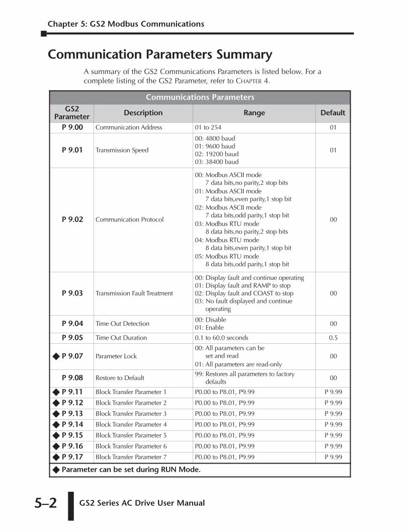
Chapter 5: GS2 Modbus Communications
GS2 Series AC Drive User Manual 5–2
Communication Parameters SummaryA summary of the GS2 Communications Parameters is listed below. For acomplete listing of the GS2 Parameter, refer to CHAPTER 4.
Communications ParametersGS2
Parameter Description Range Default
P 9.00 Communication Address 01 to 254 01
P 9.01 Transmission Speed
00: 4800 baud01: 9600 baud02: 19200 baud03: 38400 baud
01
P 9.02 Communication Protocol
00: Modbus ASCII mode7 data bits,no parity,2 stop bits
01: Modbus ASCII mode7 data bits,even parity,1 stop bit
02: Modbus ASCII mode 7 data bits,odd parity,1 stop bit
03: Modbus RTU mode 8 data bits,no parity,2 stop bits
04: Modbus RTU mode 8 data bits,even parity,1 stop bit
05: Modbus RTU mode 8 data bits,odd parity,1 stop bit
00
P 9.03 Transmission Fault Treatment
00: Display fault and continue operating01: Display fault and RAMP to stop02: Display fault and COAST to stop03: No fault displayed and continue
operating
00
P 9.04 Time Out Detection00: Disable01: Enable
00
P 9.05 Time Out Duration 0.1 to 60.0 seconds 0.5
�� P 9.07 Parameter Lock00: All parameters can be
set and read01: All parameters are read-only
00
P 9.08 Restore to Default99: Restores all parameters to factory
defaults00
�� P 9.11 Block Transfer Parameter 1 P0.00 to P8.01, P9.99 P 9.99
�� P 9.12 Block Transfer Parameter 2 P0.00 to P8.01, P9.99 P 9.99
�� P 9.13 Block Transfer Parameter 3 P0.00 to P8.01, P9.99 P 9.99
�� P 9.14 Block Transfer Parameter 4 P0.00 to P8.01, P9.99 P 9.99
�� P 9.15 Block Transfer Parameter 5 P0.00 to P8.01, P9.99 P 9.99
�� P 9.16 Block Transfer Parameter 6 P0.00 to P8.01, P9.99 P 9.99
�� P 9.17 Block Transfer Parameter 7 P0.00 to P8.01, P9.99 P 9.99
�� Parameter can be set during RUN Mode.
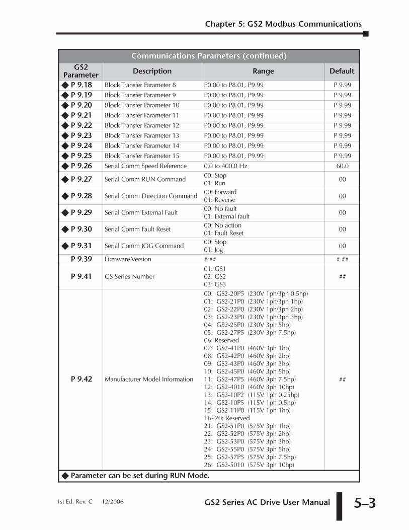
GS2 Series AC Drive User Manual 5–3
Communications Parameters (continued)GS2
Parameter Description Range Default
�� P 9.18 Block Transfer Parameter 8 P0.00 to P8.01, P9.99 P 9.99
�� P 9.19 Block Transfer Parameter 9 P0.00 to P8.01, P9.99 P 9.99
�� P 9.20 Block Transfer Parameter 10 P0.00 to P8.01, P9.99 P 9.99
�� P 9.21 Block Transfer Parameter 11 P0.00 to P8.01, P9.99 P 9.99
�� P 9.22 Block Transfer Parameter 12 P0.00 to P8.01, P9.99 P 9.99
�� P 9.23 Block Transfer Parameter 13 P0.00 to P8.01, P9.99 P 9.99
�� P 9.24 Block Transfer Parameter 14 P0.00 to P8.01, P9.99 P 9.99
�� P 9.25 Block Transfer Parameter 15 P0.00 to P8.01, P9.99 P 9.99
�� P 9.26 Serial Comm Speed Reference 0.0 to 400.0 Hz 60.0
�� P 9.27 Serial Comm RUN Command00: Stop01: Run
00
�� P 9.28 Serial Comm Direction Command00: Forward01: Reverse
00
�� P 9.29 Serial Comm External Fault00: No fault01: External fault
00
�� P 9.30 Serial Comm Fault Reset00: No action01: Fault Reset
00
�� P 9.31 Serial Comm JOG Command00: Stop01: Jog
00
P 9.39 Firmware Version #.## #.##
P 9.41 GS Series Number01: GS102: GS203: GS3
##
P 9.42 Manufacturer Model Information
00: GS2-20P5 (230V 1ph/3ph 0.5hp)01: GS2-21P0 (230V 1ph/3ph 1hp)02: GS2-22P0 (230V 1ph/3ph 2hp)03: GS2-23P0 (230V 1ph/3ph 3hp)04: GS2-25P0 (230V 3ph 5hp)05: GS2-27P5 (230V 3ph 7.5hp)06: Reserved07: GS2-41P0 (460V 3ph 1hp)08: GS2-42P0 (460V 3ph 2hp)09: GS2-43P0 (460V 3ph 3hp)10: GS2-45P0 (460V 3ph 5hp)11: GS2-47P5 (460V 3ph 7.5hp)12: GS2-4010 (460V 3ph 10hp)13: GS2-10P2 (115V 1ph 0.25hp)14: GS2-10P5 (115V 1ph 0.5hp)15: GS2-11P0 (115V 1ph 1hp)16~20: Reserved21: GS2-51P0 (575V 3ph 1hp)22: GS2-52P0 (575V 3ph 2hp)23: GS2-53P0 (575V 3ph 3hp)24: GS2-55P0 (575V 3ph 5hp)25: GS2-57P5 (575V 3ph 7.5hp)26: GS2-5010 (575V 3ph 10hp)
##
�� Parameter can be set during RUN Mode.
Chapter 5: GS2 Modbus Communications
1st Ed. Rev. C 12/2006
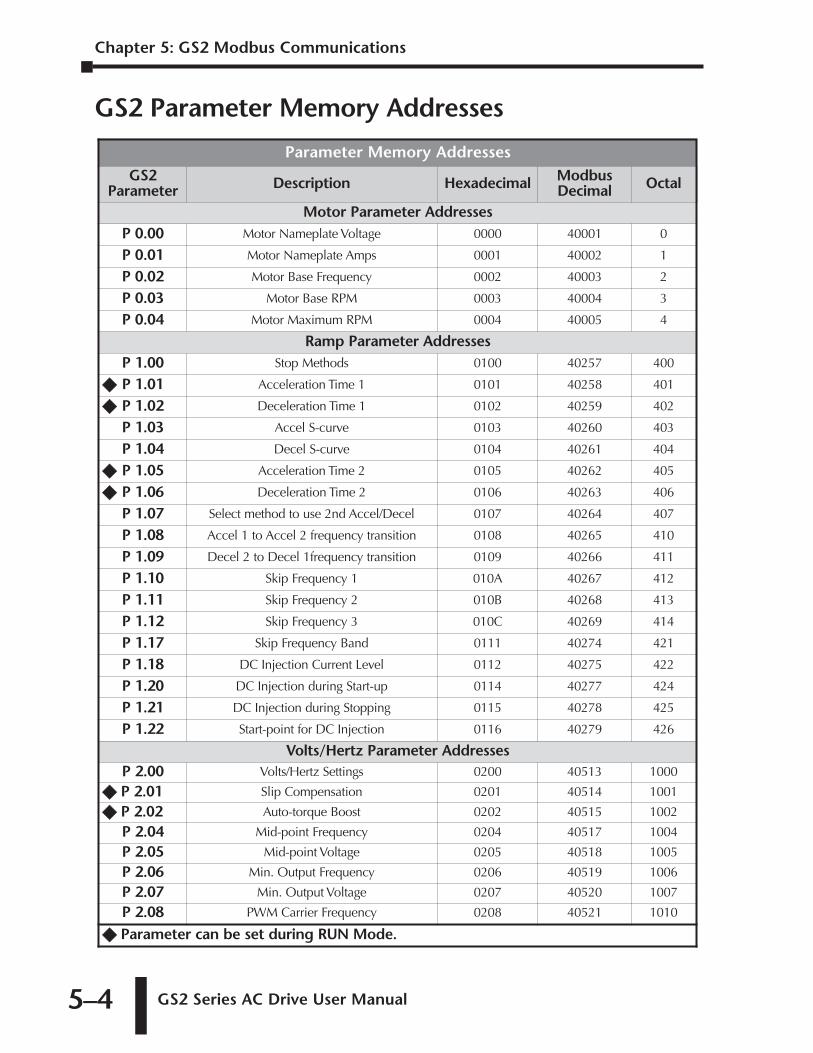
Chapter 5: GS2 Modbus Communications
GS2 Series AC Drive User Manual 5–4
GS2 Parameter Memory Addresses
Parameter Memory AddressesGS2
Parameter Description Hexadecimal ModbusDecimal Octal
Motor Parameter AddressesP 0.00 Motor Nameplate Voltage 0000 40001 0
P 0.01 Motor Nameplate Amps 0001 40002 1
P 0.02 Motor Base Frequency 0002 40003 2
P 0.03 Motor Base RPM 0003 40004 3
P 0.04 Motor Maximum RPM 0004 40005 4
Ramp Parameter AddressesP 1.00 Stop Methods 0100 40257 400
�� P 1.01 Acceleration Time 1 0101 40258 401
�� P 1.02 Deceleration Time 1 0102 40259 402
P 1.03 Accel S-curve 0103 40260 403
P 1.04 Decel S-curve 0104 40261 404
�� P 1.05 Acceleration Time 2 0105 40262 405
�� P 1.06 Deceleration Time 2 0106 40263 406
P 1.07 Select method to use 2nd Accel/Decel 0107 40264 407
P 1.08 Accel 1 to Accel 2 frequency transition 0108 40265 410
P 1.09 Decel 2 to Decel 1frequency transition 0109 40266 411
P 1.10 Skip Frequency 1 010A 40267 412
P 1.11 Skip Frequency 2 010B 40268 413
P 1.12 Skip Frequency 3 010C 40269 414
P 1.17 Skip Frequency Band 0111 40274 421
P 1.18 DC Injection Current Level 0112 40275 422
P 1.20 DC Injection during Start-up 0114 40277 424
P 1.21 DC Injection during Stopping 0115 40278 425
P 1.22 Start-point for DC Injection 0116 40279 426
Volts/Hertz Parameter AddressesP 2.00 Volts/Hertz Settings 0200 40513 1000
�� P 2.01 Slip Compensation 0201 40514 1001
�� P 2.02 Auto-torque Boost 0202 40515 1002
P 2.04 Mid-point Frequency 0204 40517 1004
P 2.05 Mid-point Voltage 0205 40518 1005
P 2.06 Min. Output Frequency 0206 40519 1006
P 2.07 Min. Output Voltage 0207 40520 1007
P 2.08 PWM Carrier Frequency 0208 40521 1010
�� Parameter can be set during RUN Mode.
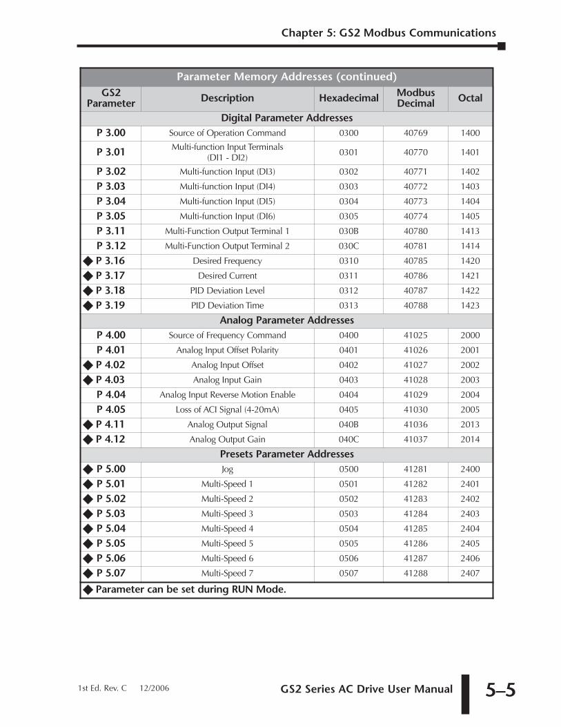
GS2 Series AC Drive User Manual 5–5
Parameter Memory Addresses (continued)GS2
Parameter Description Hexadecimal ModbusDecimal Octal
Digital Parameter AddressesP 3.00 Source of Operation Command 0300 40769 1400
P 3.01 Multi-function Input Terminals (DI1 - DI2)
0301 40770 1401
P 3.02 Multi-function Input (DI3) 0302 40771 1402
P 3.03 Multi-function Input (DI4) 0303 40772 1403
P 3.04 Multi-function Input (DI5) 0304 40773 1404
P 3.05 Multi-function Input (DI6) 0305 40774 1405
P 3.11 Multi-Function Output Terminal 1 030B 40780 1413
P 3.12 Multi-Function Output Terminal 2 030C 40781 1414
�� P 3.16 Desired Frequency 0310 40785 1420
�� P 3.17 Desired Current 0311 40786 1421
�� P 3.18 PID Deviation Level 0312 40787 1422
�� P 3.19 PID Deviation Time 0313 40788 1423
Analog Parameter AddressesP 4.00 Source of Frequency Command 0400 41025 2000
P 4.01 Analog Input Offset Polarity 0401 41026 2001
�� P 4.02 Analog Input Offset 0402 41027 2002
�� P 4.03 Analog Input Gain 0403 41028 2003
P 4.04 Analog Input Reverse Motion Enable 0404 41029 2004
P 4.05 Loss of ACI Signal (4-20mA) 0405 41030 2005
�� P 4.11 Analog Output Signal 040B 41036 2013
�� P 4.12 Analog Output Gain 040C 41037 2014
Presets Parameter Addresses�� P 5.00 Jog 0500 41281 2400
�� P 5.01 Multi-Speed 1 0501 41282 2401
�� P 5.02 Multi-Speed 2 0502 41283 2402
�� P 5.03 Multi-Speed 3 0503 41284 2403
�� P 5.04 Multi-Speed 4 0504 41285 2404
�� P 5.05 Multi-Speed 5 0505 41286 2405
�� P 5.06 Multi-Speed 6 0506 41287 2406
�� P 5.07 Multi-Speed 7 0507 41288 2407
�� Parameter can be set during RUN Mode.
Chapter 5: GS2 Modbus Communications
1st Ed. Rev. C 12/2006
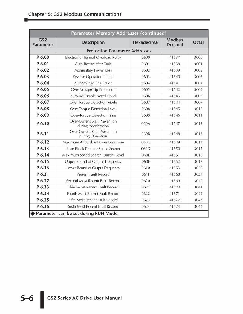
Chapter 5: GS2 Modbus Communications
GS2 Series AC Drive User Manual 5–6
Parameter Memory Addresses (continued)GS2
Parameter Description Hexadecimal ModbusDecimal Octal
Protection Parameter AddressesP 6.00 Electronic Thermal Overload Relay 0600 41537 3000
P 6.01 Auto Restart after Fault 0601 41538 3001
P 6.02 Momentary Power Loss 0602 41539 3002
P 6.03 Reverse Operation Inhibit 0603 41540 3003
P 6.04 Auto Voltage Regulation 0604 41541 3004
P 6.05 Over-VoltageTrip Protection 0605 41542 3005
P 6.06 Auto Adjustable Accel/Decel 0606 41543 3006
P 6.07 Over-Torque Detection Mode 0607 41544 3007
P 6.08 Over-Torque Detection Level 0608 41545 3010
P 6.09 Over-Torque Detection Time 0609 41546 3011
P 6.10 Over-Current Stall Prevention during Acceleration
060A 41547 3012
P 6.11 Over-Current Stall Prevention during Operation
060B 41548 3013
P 6.12 Maximum Allowable Power Loss Time 060C 41549 3014
P 6.13 Base-Block Time for Speed Search 060D 41550 3015
P 6.14 Maximum Speed Search Current Level 060E 41551 3016
P 6.15 Upper Bound of Output Frequency 060F 41552 3017
P 6.16 Lower Bound of Output Frequency 0610 41553 3020
P 6.31 Present Fault Record 061F 41568 3037
P 6.32 Second Most Recent Fault Record 0620 41569 3040
P 6.33 Third Most Recent Fault Record 0621 41570 3041
P 6.34 Fourth Most Recent Fault Record 0622 41571 3042
P 6.35 Fifth Most Recent Fault Record 0623 41572 3043
P 6.36 Sixth Most Recent Fault Record 0624 41573 3044
�� Parameter can be set during RUN Mode.
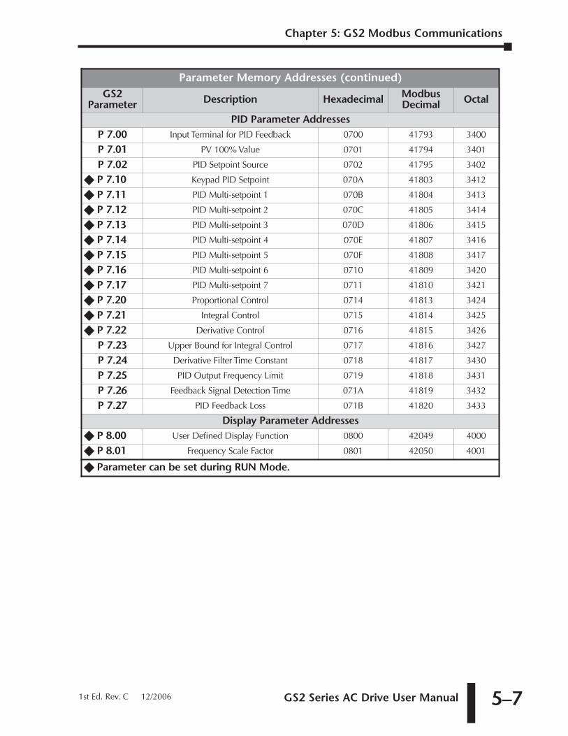
GS2 Series AC Drive User Manual 5–7
Parameter Memory Addresses (continued)GS2
Parameter Description Hexadecimal ModbusDecimal Octal
PID Parameter Addresses P 7.00 Input Terminal for PID Feedback 0700 41793 3400
P 7.01 PV 100% Value 0701 41794 3401
P 7.02 PID Setpoint Source 0702 41795 3402
�� P 7.10 Keypad PID Setpoint 070A 41803 3412
�� P 7.11 PID Multi-setpoint 1 070B 41804 3413
�� P 7.12 PID Multi-setpoint 2 070C 41805 3414
�� P 7.13 PID Multi-setpoint 3 070D 41806 3415
�� P 7.14 PID Multi-setpoint 4 070E 41807 3416
�� P 7.15 PID Multi-setpoint 5 070F 41808 3417
�� P 7.16 PID Multi-setpoint 6 0710 41809 3420
�� P 7.17 PID Multi-setpoint 7 0711 41810 3421
�� P 7.20 Proportional Control 0714 41813 3424
�� P 7.21 Integral Control 0715 41814 3425
�� P 7.22 Derivative Control 0716 41815 3426
P 7.23 Upper Bound for Integral Control 0717 41816 3427
P 7.24 Derivative Filter Time Constant 0718 41817 3430
P 7.25 PID Output Frequency Limit 0719 41818 3431
P 7.26 Feedback Signal Detection Time 071A 41819 3432
P 7.27 PID Feedback Loss 071B 41820 3433
Display Parameter Addresses �� P 8.00 User Defined Display Function 0800 42049 4000
�� P 8.01 Frequency Scale Factor 0801 42050 4001
�� Parameter can be set during RUN Mode.
Chapter 5: GS2 Modbus Communications
1st Ed. Rev. C 12/2006
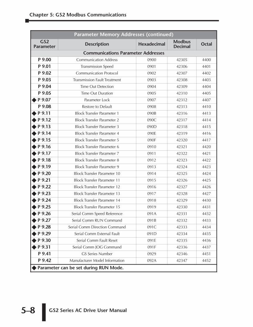
Chapter 5: GS2 Modbus Communications
GS2 Series AC Drive User Manual 5–8
Parameter Memory Addresses (continued)GS2
Parameter Description Hexadecimal ModbusDecimal Octal
Communications Parameter Addresses P 9.00 Communication Address 0900 42305 4400
P 9.01 Transmission Speed 0901 42306 4401
P 9.02 Communication Protocol 0902 42307 4402
P 9.03 Transmission Fault Treatment 0903 42308 4403
P 9.04 Time Out Detection 0904 42309 4404
P 9.05 Time Out Duration 0905 42310 4405
�� P 9.07 Parameter Lock 0907 42312 4407
P 9.08 Restore to Default 0908 42313 4410
�� P 9.11 Block Transfer Parameter 1 090B 42316 4413
�� P 9.12 Block Transfer Parameter 2 090C 42317 4414
�� P 9.13 Block Transfer Parameter 3 090D 42318 4415
�� P 9.14 Block Transfer Parameter 4 090E 42319 4416
�� P 9.15 Block Transfer Parameter 5 090F 42320 4417
�� P 9.16 Block Transfer Parameter 6 0910 42321 4420
�� P 9.17 Block Transfer Parameter 7 0911 42322 4421
�� P 9.18 Block Transfer Parameter 8 0912 42323 4422
�� P 9.19 Block Transfer Parameter 9 0913 42324 4423
�� P 9.20 Block Transfer Parameter 10 0914 42325 4424
�� P 9.21 Block Transfer Parameter 11 0915 42326 4425
�� P 9.22 Block Transfer Parameter 12 0916 42327 4426
�� P 9.23 Block Transfer Parameter 13 0917 42328 4427
�� P 9.24 Block Transfer Parameter 14 0918 42329 4430
�� P 9.25 Block Transfer Parameter 15 0919 42330 4431
�� P 9.26 Serial Comm Speed Reference 091A 42331 4432
�� P 9.27 Serial Comm RUN Command 091B 42332 4433
�� P 9.28 Serial Comm Direction Command 091C 42333 4434
�� P 9.29 Serial Comm External Fault 091D 42334 4435
�� P 9.30 Serial Comm Fault Reset 091E 42335 4436
�� P 9.31 Serial Comm JOG Command 091F 42336 4437
P 9.41 GS Series Number 0929 42346 4451
P 9.42 Manufacturer Model Information 092A 42347 4452
�� Parameter can be set during RUN Mode.
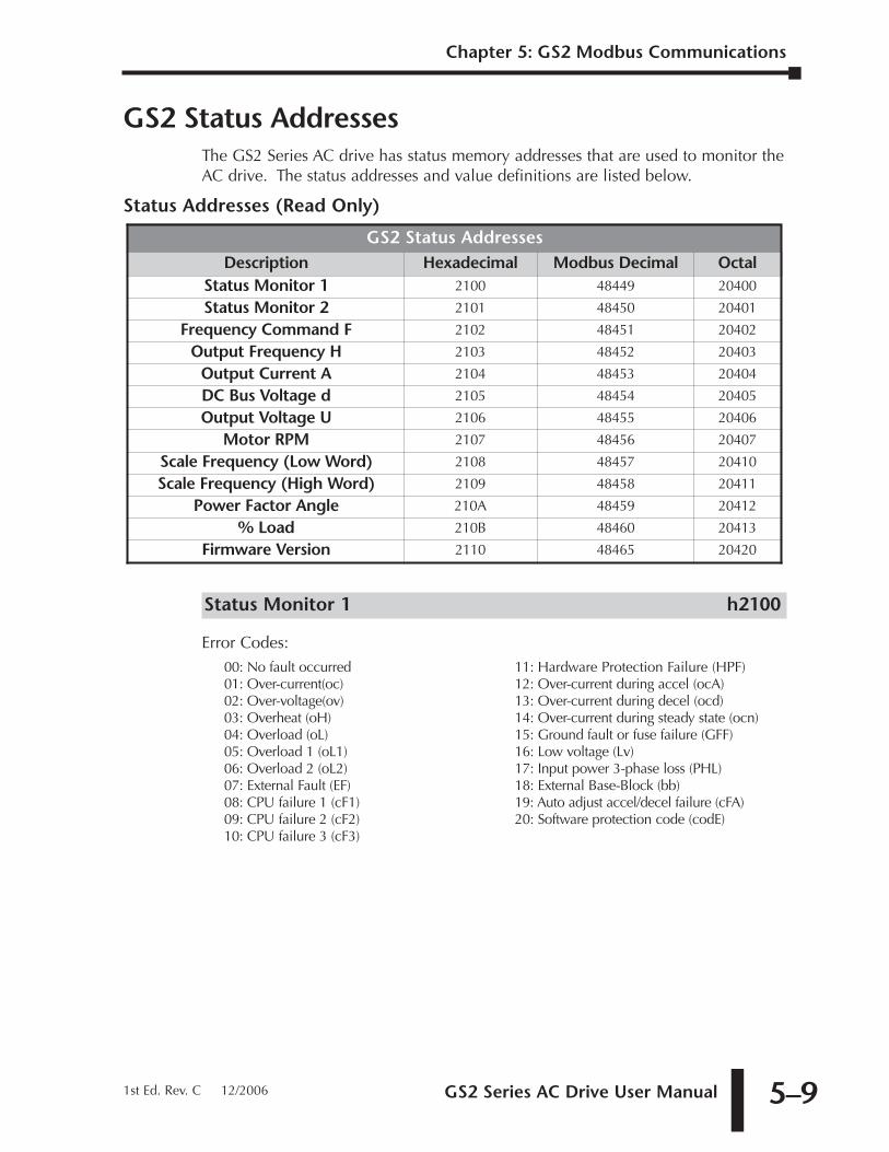
GS2 Series AC Drive User Manual 5–9
GS2 Status AddressesThe GS2 Series AC drive has status memory addresses that are used to monitor theAC drive. The status addresses and value definitions are listed below.
Status Addresses (Read Only)
Status Monitor 1 h2100
Error Codes:00: No fault occurred01: Over-current(oc)02: Over-voltage(ov)03: Overheat (oH)04: Overload (oL)05: Overload 1 (oL1)06: Overload 2 (oL2)07: External Fault (EF)08: CPU failure 1 (cF1)09: CPU failure 2 (cF2)10: CPU failure 3 (cF3)
11: Hardware Protection Failure (HPF)12: Over-current during accel (ocA)13: Over-current during decel (ocd)14: Over-current during steady state (ocn)15: Ground fault or fuse failure (GFF)16: Low voltage (Lv)17: Input power 3-phase loss (PHL)18: External Base-Block (bb)19: Auto adjust accel/decel failure (cFA)20: Software protection code (codE)
GS2 Status AddressesDescription Hexadecimal Modbus Decimal Octal
Status Monitor 1 2100 48449 20400
Status Monitor 2 2101 48450 20401
Frequency Command F 2102 48451 20402
Output Frequency H 2103 48452 20403
Output Current A 2104 48453 20404
DC Bus Voltage d 2105 48454 20405
Output Voltage U 2106 48455 20406
Motor RPM 2107 48456 20407
Scale Frequency (Low Word) 2108 48457 20410
Scale Frequency (High Word) 2109 48458 20411
Power Factor Angle 210A 48459 20412
% Load 210B 48460 20413
Firmware Version 2110 48465 20420
Chapter 5: GS2 Modbus Communications
1st Ed. Rev. C 12/2006
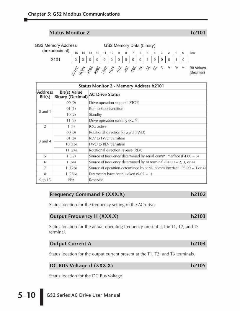
Chapter 5: GS2 Modbus Communications
GS2 Series AC Drive User Manual 5–10
Status Monitor 2 h2101
Frequency Command F (XXX.X) h2102
Status location for the frequency setting of the AC drive.
Output Frequency H (XXX.X) h2103
Status location for the actual operating frequency present at the T1, T2, and T3terminal.
Output Current A h2104
Status location for the output current present at the T1, T2, and T3 terminals.
DC-BUS Voltage d (XXX.X) h2105
Status location for the DC Bus Voltage.
Status Monitor 2 - Memory Address h2101Address
Bit(s)Bit(s) Value
Binary (Decimal) AC Drive Status
0 and 1
00 (0) Drive operation stopped (STOP)
01 (1) Run to Stop transition
10 (2) Standby
11 (3) Drive operation running (RUN)
2 1 (4) JOG active
3 and 4
00 (0) Rotational direction forward (FWD)
01 (8) REV to FWD transition
10 (16) FWD to REV transition
11 (24) Rotational direction reverse (REV)
5 1 (32) Source of frequency determined by serial comm interface (P4.00 = 5)
6 1 (64) Source of frequency determined by AI terminal (P4.00 = 2, 3, or 4)
7 1 (128) Source of operation determined by serial comm interface (P3.00 = 3 or 4)
8 1 (256) Parameters have been locked (9-07 = 1)
9 to 15 N/A Reserved
Bits15 01234567891011121314
0 010001000000000
GS2 Memory Data (binary)GS2 Memory Address
(hexadecimal)
2101
32768 248
16
32
64
128
256
512
1024
2048
4096
8192
16384 1 Bit Values
(decimal)
GS2 Series AC Drive User Manual 5–11
Output Voltage U (XXX.X) h2106
Status location for the output voltage present at the T1, T2, and T3 terminals.
Motor RPM h2107
Status location for the present estimated speed of the motor.
Scale Frequency (Low word) h2108
Status location for result of output frequency x P 8.01 (low word).
Scale Frequency (High word) h2109
Status location for result of output frequency x P 8.01 (high word).
Power Factor Angle h210A
Status location for the power factor angle.
% Load h210B
Status location for the amount of load on the AC drive. (Output Current ÷ DriveRated Current) x 100.
Firmware Version h2110
Status location for the firmware version of the AC drive.
Chapter 5: GS2 Modbus Communications
1st Ed. Rev. C 12/2006
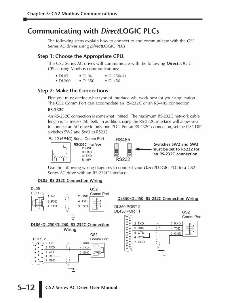
Chapter 5: GS2 Modbus Communications
GS2 Series AC Drive User Manual 5–12
Communicating with DirectLOGIC PLCsThe following steps explain how to connect to and communicate with the GS2Series AC drives using DirectLOGIC PLCs.
Step 1: Choose the Appropriate CPU.The GS2 Series AC drives will communicate with the following DirectLOGICCPUs using Modbus communications:
• DL05 • DL06 • DL250(-1)• DL260 • DL350 • DL450
Step 2: Make the ConnectionsFirst you must decide what type of interface will work best for your application.The GS2 Comm Port can accomodate an RS-232C or an RS-485 connection.
RS-232C
An RS-232C connection is somewhat limited. The maximum RS-232C network cablelength is 15 meters (50 feet). In addition, using the RS-232C interface will allow youto connect an AC drive to only one PLC. For an RS-232C connection, set the GS2 DIPswitches SW2 and SW3 to RS232.
Use the following wiring diagrams to connect your DirectLOGIC PLC to a GS2Series AC drive with an RS-232C interface:
1 0V
3 RXD
4 TXD
DL05
PORT 2
GS2
Comm Port2 GND
3 RXD
4 TXD
DL05: RS-232C Connection Wiring
2 TXD
3 RXD
5 CTS
4 RTS
PORT 2
GS2
Comm Port
3 RXD
2 GND
4 TXD
1
15
6
7 GND
DL06/DL250/DL260: RS-232C ConnectionWiring
DL350 PORT 2
DL450 PORT 1 GS2
Comm Port1
25
2 TXD
3 RXD
5 CTS
4 RTS
3 RXD
2 GND
4 TXD
7 GND
DL350/DL450: RS-232C Connection Wiring
RS485
RS232SW3 SW2
Switches SW2 and SW3must be set to RS232 foran RS-232C connection.
RJ-12 (6P4C) Serial Comm Port
16
2: GND3: RXD4: TXD5: +5V
RS-232C Interface
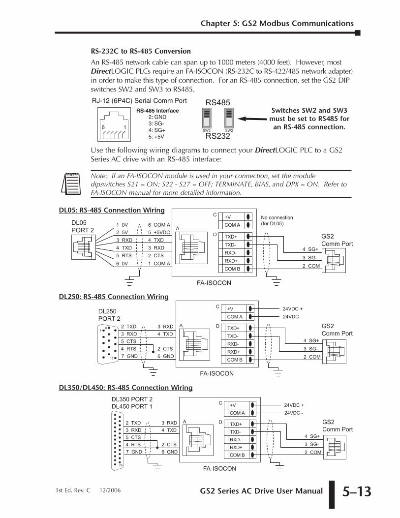
GS2 Series AC Drive User Manual 5–13
RS-232C to RS-485 Conversion
An RS-485 network cable can span up to 1000 meters (4000 feet). However, mostDirectLOGIC PLCs require an FA-ISOCON (RS-232C to RS-422/485 network adapter)in order to make this type of connection. For an RS-485 connection, set the GS2 DIPswitches SW2 and SW3 to RS485.
Use the following wiring diagrams to connect your DirectLOGIC PLC to a GS2Series AC drive with an RS-485 interface:
DL350 PORT 2 DL450 PORT 1
2 TXD3 RXD5 CTS4 RTS
3 RXD 4 TXD
2 CTS6 GND7 GND
1
25
GS2Comm Port
FA-ISOCON
A TXD+TXD-RXD-RXD+COM B
D
+VCOM A
C
4 SG+
2 COM
3 SG-
24VDC +24VDC -
DL350/DL450: RS-485 Connection Wiring
GS2Comm Port
DL250PORT 2
1
15
6 2 TXD3 RXD5 CTS4 RTS
3 RXD 4 TXD
2 CTS6 GND7 GND
FA-ISOCON
A TXD+TXD-RXD-RXD+COM B
D
+VCOM A
C
4 SG+
2 COM
3 SG-
24VDC +24VDC -
DL250: RS-485 Connection Wiring
DL05PORT 2
GS2Comm Port
2 5V3 RXD4 TXD5 RTS
5 +5VDC
3 RXD4 TXD
2 CTS6 0V 1 COM A
1 0V 6 COM A
FA-ISOCON
A
TXD+TXD-RXD-RXD+COM B
D
+VCOM A
C
4 SG+
2 COM
3 SG-
No connection(for DL05)
DL05: RS-485 Connection Wiring
Note: If an FA-ISOCON module is used in your connection, set the moduledipswitches S21 = ON; S22 - S27 = OFF; TERMINATE, BIAS, and DPX = ON. Refer toFA-ISOCON manual for more detailed information.
RS485
RS232SW3 SW2
Switches SW2 and SW3must be set to RS485 for
an RS-485 connection.
RJ-12 (6P4C) Serial Comm Port
16
RS-485 Interface2: GND3: SG-4: SG+5: +5V
Chapter 5: GS2 Modbus Communications
1st Ed. Rev. C 12/2006
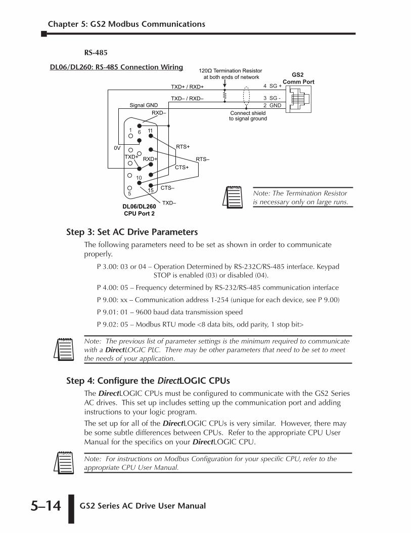
Chapter 5: GS2 Modbus Communications
GS2 Series AC Drive User Manual 5–14
RS-485
Step 3: Set AC Drive ParametersThe following parameters need to be set as shown in order to communicateproperly.
P 3.00: 03 or 04 – Operation Determined by RS-232C/RS-485 interface. KeypadSTOP is enabled (03) or disabled (04).
P 4.00: 05 – Frequency determined by RS-232/RS-485 communication interface
P 9.00: xx – Communication address 1-254 (unique for each device, see P 9.00)
P 9.01: 01 – 9600 baud data transmission speed
P 9.02: 05 – Modbus RTU mode <8 data bits, odd parity, 1 stop bit>
Step 4: Configure the DirectLOGIC CPUsThe DirectLOGIC CPUs must be configured to communicate with the GS2 SeriesAC drives. This set up includes setting up the communication port and addinginstructions to your logic program.
The set up for all of the DirectLOGIC CPUs is very similar. However, there maybe some subtle differences between CPUs. Refer to the appropriate CPU UserManual for the specifics on your DirectLOGIC CPU.
Note: For instructions on Modbus Configuration for your specific CPU, refer to theappropriate CPU User Manual.
Note: The previous list of parameter settings is the minimum required to communicatewith a DirectLOGIC PLC. There may be other parameters that need to be set to meetthe needs of your application.
120� Termination Resistor at both ends of network
Connect shieldto signal ground
TXD+
TXD–
RXD–
15
RXD+
0V
11
TXD+ / RXD+
Signal GNDTXD– / RXD–
RTS+
RTS–CTS+
CTS–
DL06/DL260CPU Port 2
GS2 Comm Port
2 GND3 SG -
4 SG +
10
1 6
5
DL06/DL260: RS-485 Connection Wiring
Note: The Termination Resistoris necessary only on large runs.
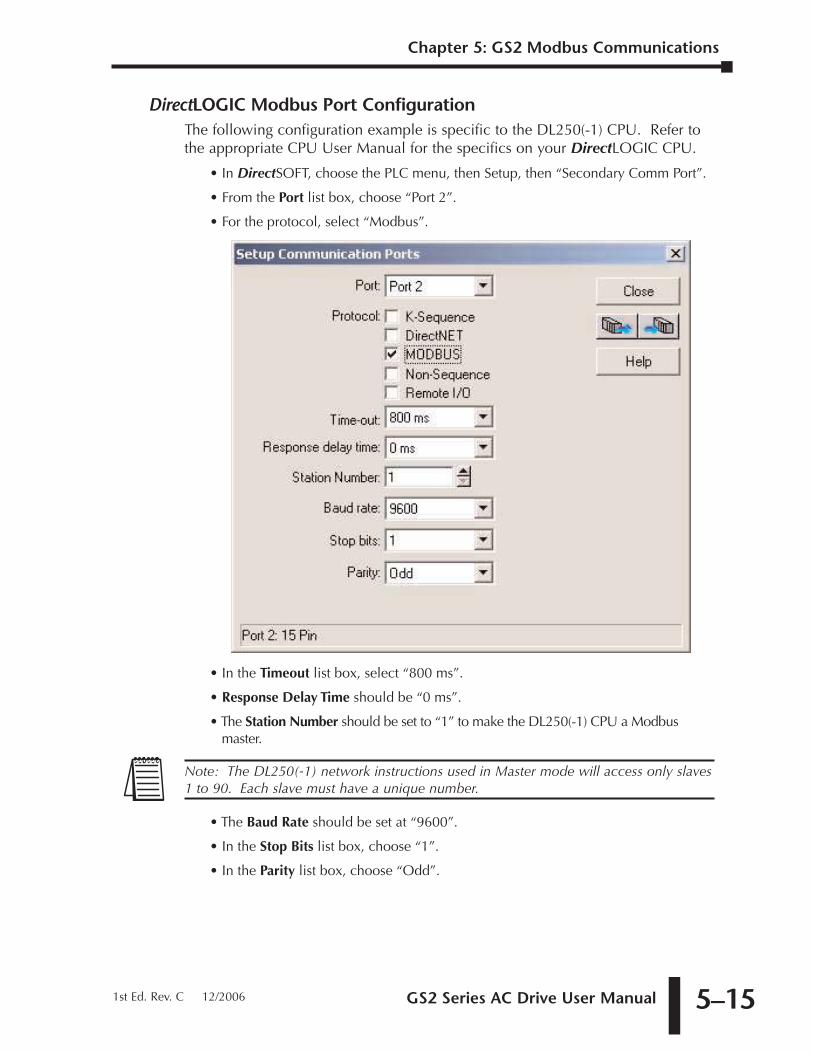
GS2 Series AC Drive User Manual 5–15
DirectLOGIC Modbus Port ConfigurationThe following configuration example is specific to the DL250(-1) CPU. Refer tothe appropriate CPU User Manual for the specifics on your DirectLOGIC CPU.
• In DirectSOFT, choose the PLC menu, then Setup, then “Secondary Comm Port”.
• From the Port list box, choose “Port 2”.
• For the protocol, select “Modbus”.
• In the Timeout list box, select “800 ms”.
• Response Delay Time should be “0 ms”.
• The Station Number should be set to “1” to make the DL250(-1) CPU a Modbusmaster.
• The Baud Rate should be set at “9600”.
• In the Stop Bits list box, choose “1”.
• In the Parity list box, choose “Odd”.
Note: The DL250(-1) network instructions used in Master mode will access only slaves1 to 90. Each slave must have a unique number.
Chapter 5: GS2 Modbus Communications
1st Ed. Rev. C 12/2006
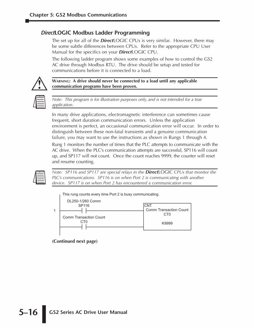
Chapter 5: GS2 Modbus Communications
GS2 Series AC Drive User Manual 5–16
DirectLOGIC Modbus Ladder ProgrammingThe set up for all of the DirectLOGIC CPUs is very similar. However, there maybe some subtle differences between CPUs. Refer to the appropriate CPU UserManual for the specifics on your DirectLOGIC CPU.
The following ladder program shows some examples of how to control the GS2AC drive through Modbus RTU. The drive should be setup and tested forcommunications before it is connected to a load.
In many drive applications, electromagnetic interference can sometimes causefrequent, short duration communication errors. Unless the applicationenvironment is perfect, an occasional communication error will occur. In order todistinguish between these non-fatal transients and a genuine communicationfailure, you may want to use the instructions as shown in Rungs 1 through 4.
Rung 1 monitors the number of times that the PLC attempts to communicate with theAC drive. When the PLC’s communication attempts are successful, SP116 will countup, and SP117 will not count. Once the count reaches 9999, the counter will resetand resume counting.
(Continued next page)
DL250-1/260 CommSP116
Comm Transaction CountCT0
Comm Transaction CountCT0
K9999
CNT1
This rung counts every time Port 2 is busy communicating.
Note: SP116 and SP117 are special relays in the DirectLOGIC CPUs that monitor thePLC’s communications. SP116 is on when Port 2 is communicating with anotherdevice. SP117 is on when Port 2 has encountered a communication error.
Note: This program is for illustration purposes only, and is not intended for a trueapplication.
WARNING: A drive should never be connected to a load until any applicablecommunication programs have been proven.
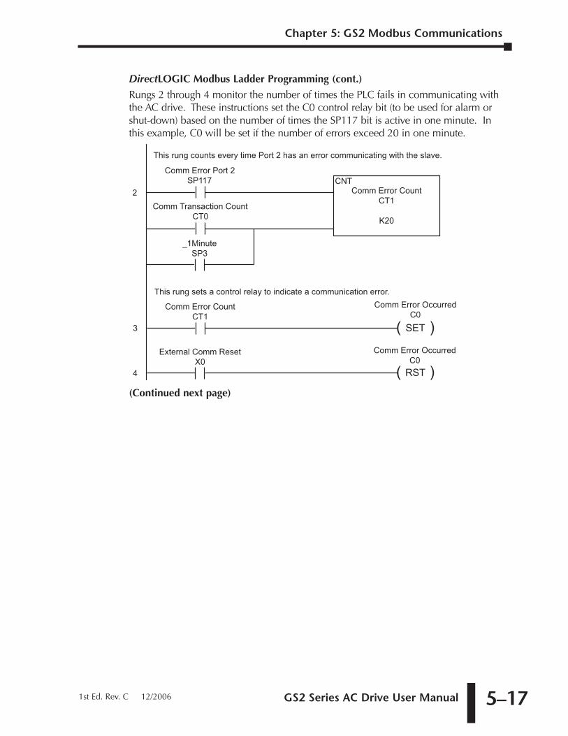
GS2 Series AC Drive User Manual 5–17
DirectLOGIC Modbus Ladder Programming (cont.)
Rungs 2 through 4 monitor the number of times the PLC fails in communicating withthe AC drive. These instructions set the C0 control relay bit (to be used for alarm orshut-down) based on the number of times the SP117 bit is active in one minute. Inthis example, C0 will be set if the number of errors exceed 20 in one minute.
(Continued next page)
Comm Error Port 2SP117
Comm Transaction CountCT0
_1MinuteSP3
Comm Error CountCT1
K20
CNT2
This rung counts every time Port 2 has an error communicating with the slave.
3 ( )SET
Comm Error OccurredC0
Comm Error CountCT1
External Comm ResetX0
4 ( )RST
Comm Error OccurredC0
This rung sets a control relay to indicate a communication error.
Chapter 5: GS2 Modbus Communications
1st Ed. Rev. C 12/2006
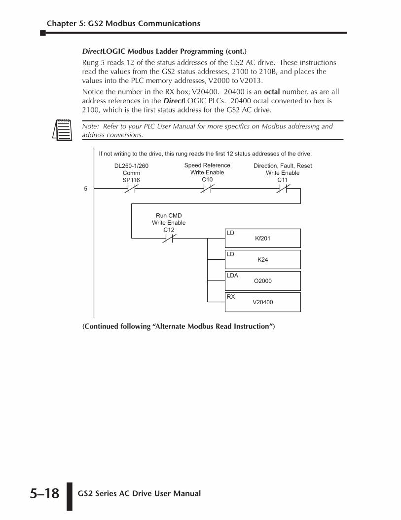
Chapter 5: GS2 Modbus Communications
GS2 Series AC Drive User Manual 5–18
DirectLOGIC Modbus Ladder Programming (cont.)
Rung 5 reads 12 of the status addresses of the GS2 AC drive. These instructionsread the values from the GS2 status addresses, 2100 to 210B, and places thevalues into the PLC memory addresses, V2000 to V2013.
Notice the number in the RX box; V20400. 20400 is an octal number, as are alladdress references in the DirectLOGIC PLCs. 20400 octal converted to hex is2100, which is the first status address for the GS2 AC drive.
(Continued following “Alternate Modbus Read Instruction”)
Kf201LD
V20400RX
O2000LDA
K24LD
5
DL250-1/260CommSP116
Speed ReferenceWrite Enable
C10
Direction, Fault, ResetWrite Enable
C11
Run CMDWrite Enable
C12
If not writing to the drive, this rung reads the first 12 status addresses of the drive.
Note: Refer to your PLC User Manual for more specifics on Modbus addressing andaddress conversions.
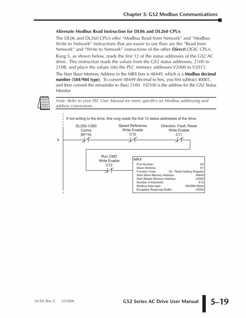
GS2 Series AC Drive User Manual 5–19
Alternate Modbus Read Instruction for DL06 and DL260 CPUs
The DL06 and DL260 CPUs offer “Modbus Read from Network” and “ModbusWrite to Network” instructions that are easier to use than are the “Read fromNetwork” and “Write to Network” instructions of the other DirectLOGIC CPUs.
Rung 5, as shown below, reads the first 12 of the status addresses of the GS2 ACdrive. This instruction reads the values from the GS2 status addresses, 2100 to210B, and place the values into the PLC memory addresses V2000 to V2013.
The Start Slave Memory Address in the MRX box is 48449, which is a Modbus decimalnumber (584/984 type). To convert 48449 decimal to hex, you first subtract 40001,and then convert the remainder to (hex) 2100. H2100 is the address for the GS2 StatusMonitor.
MRXPort Number:Slave Address:Function Code:Start Slave Memory Address:Start Master Memory Address:Number of Elements:Modbus Data type:Exception Response Buffer:
K2K1
03 - Read Holding Register48449V2000
K12584/984 Mode
V5000
5
DL250-1/260CommSP116
Speed ReferenceWrite Enable
C10
Direction, Fault, ResetWrite Enable
C11
Run CMDWrite Enable
C12
If not writing to the drive, this rung reads the first 12 status addresses of the drive.
Note: Refer to your PLC User Manual for more specifics on Modbus addressing andaddress conversions.
Chapter 5: GS2 Modbus Communications
1st Ed. Rev. C 12/2006
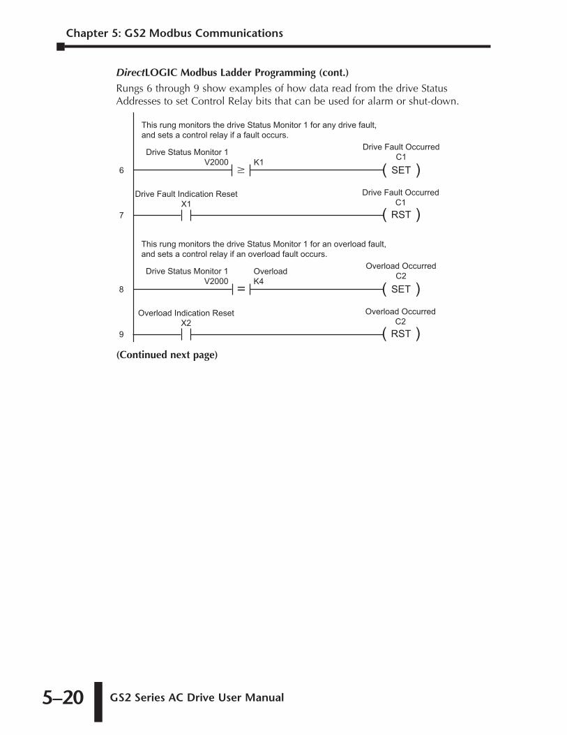
Chapter 5: GS2 Modbus Communications
GS2 Series AC Drive User Manual 5–20
DirectLOGIC Modbus Ladder Programming (cont.)
Rungs 6 through 9 show examples of how data read from the drive StatusAddresses to set Control Relay bits that can be used for alarm or shut-down.
(Continued next page)
8 ( )SET
Overload OccurredC2
Overload Indication ResetX2
9 ( )RST
Overload OccurredC2
This rung monitors the drive Status Monitor 1 for an overload fault,and sets a control relay if an overload fault occurs.
Drive Status Monitor 1V2000
=OverloadK4
6 ( )SET
Drive Fault OccurredC1
Drive Fault Indication ResetX1
7 ( )RST
Drive Fault OccurredC1
This rung monitors the drive Status Monitor 1 for any drive fault,and sets a control relay if a fault occurs.
Drive Status Monitor 1V2000 K1
�
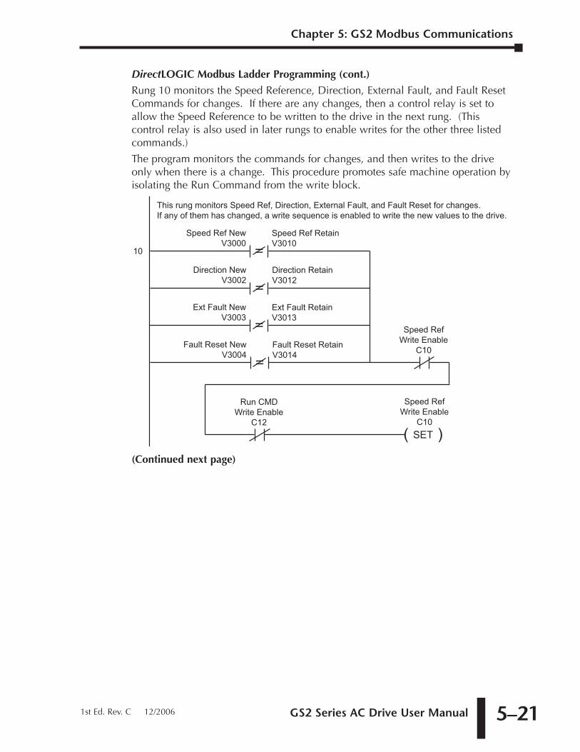
GS2 Series AC Drive User Manual 5–21
DirectLOGIC Modbus Ladder Programming (cont.)
Rung 10 monitors the Speed Reference, Direction, External Fault, and Fault ResetCommands for changes. If there are any changes, then a control relay is set toallow the Speed Reference to be written to the drive in the next rung. (Thiscontrol relay is also used in later rungs to enable writes for the other three listedcommands.)
The program monitors the commands for changes, and then writes to the driveonly when there is a change. This procedure promotes safe machine operation byisolating the Run Command from the write block.
(Continued next page)
10
This rung monitors Speed Ref, Direction, External Fault, and Fault Reset for changes.If any of them has changed, a write sequence is enabled to write the new values to the drive.
Speed Ref NewV3000
=Speed Ref RetainV3010
Direction NewV3002
=Direction RetainV3012
Ext Fault NewV3003
=Ext Fault RetainV3013
Fault Reset NewV3004
=Fault Reset RetainV3014
Speed RefWrite Enable
C10
Run CMDWrite Enable
C12( )SET
Speed RefWrite Enable
C10
Chapter 5: GS2 Modbus Communications
1st Ed. Rev. C 12/2006
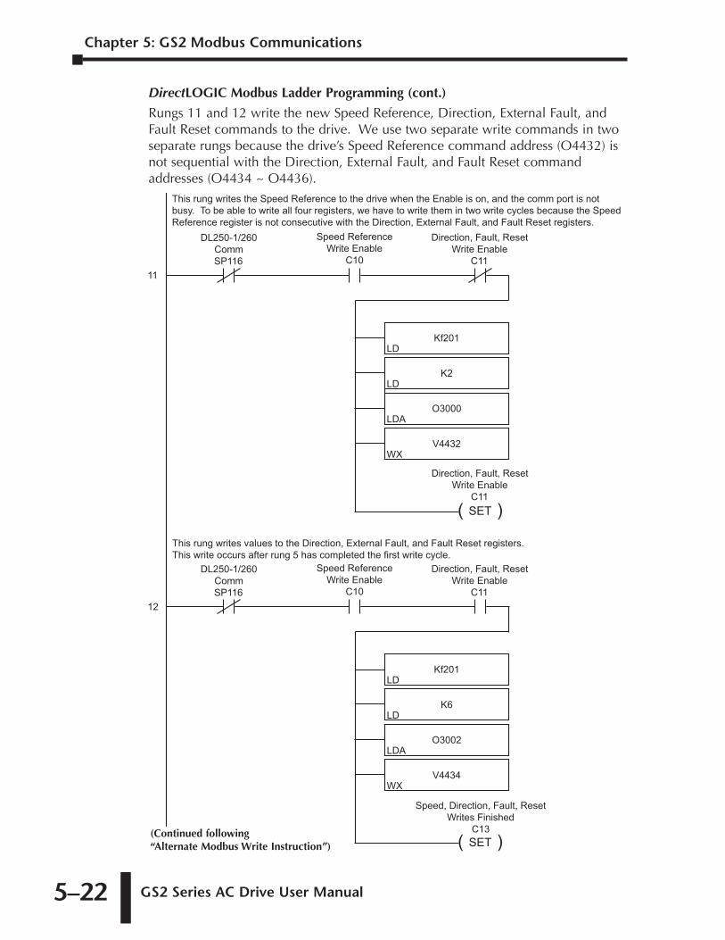
Chapter 5: GS2 Modbus Communications
GS2 Series AC Drive User Manual 5–22
DirectLOGIC Modbus Ladder Programming (cont.)
Rungs 11 and 12 write the new Speed Reference, Direction, External Fault, andFault Reset commands to the drive. We use two separate write commands in twoseparate rungs because the drive’s Speed Reference command address (O4432) isnot sequential with the Direction, External Fault, and Fault Reset commandaddresses (O4434 ~ O4436).
Kf201LD
V4432WX
O3000LDA
K2LD
11
DL250-1/260CommSP116
Speed ReferenceWrite Enable
C10
Direction, Fault, ResetWrite Enable
C11
( )SET
Direction, Fault, ResetWrite Enable
C11
Kf201LD
V4434WX
O3002LDA
K6LD
12
DL250-1/260CommSP116
Speed ReferenceWrite Enable
C10
Direction, Fault, ResetWrite Enable
C11
This rung writes the Speed Reference to the drive when the Enable is on, and the comm port is not busy. To be able to write all four registers, we have to write them in two write cycles because the SpeedReference register is not consecutive with the Direction, External Fault, and Fault Reset registers.
This rung writes values to the Direction, External Fault, and Fault Reset registers.This write occurs after rung 5 has completed the first write cycle.
( )SET
Speed, Direction, Fault, ResetWrites Finished
C13(Continued following “Alternate Modbus Write Instruction”)
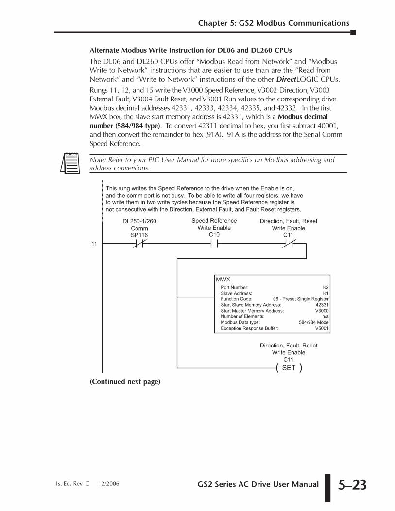
GS2 Series AC Drive User Manual 5–23
Alternate Modbus Write Instruction for DL06 and DL260 CPUs
The DL06 and DL260 CPUs offer “Modbus Read from Network” and “ModbusWrite to Network” instructions that are easier to use than are the “Read fromNetwork” and “Write to Network” instructions of the other DirectLOGIC CPUs.
Rungs 11, 12, and 15 write the V3000 Speed Reference, V3002 Direction, V3003External Fault, V3004 Fault Reset, and V3001 Run values to the corresponding driveModbus decimal addresses 42331, 42333, 42334, 42335, and 42332. In the firstMWX box, the slave start memory address is 42331, which is a Modbus decimalnumber (584/984 type). To convert 42311 decimal to hex, you first subtract 40001,and then convert the remainder to hex (91A). 91A is the address for the Serial CommSpeed Reference.
(Continued next page)
11
DL250-1/260CommSP116
Speed ReferenceWrite Enable
C10
Direction, Fault, ResetWrite Enable
C11
( )SET
Direction, Fault, ResetWrite Enable
C11
This rung writes the Speed Reference to the drive when the Enable is on, and the comm port is not busy. To be able to write all four registers, we have to write them in two write cycles because the Speed Reference register is not consecutive with the Direction, External Fault, and Fault Reset registers.
MWXPort Number:Slave Address:Function Code:Start Slave Memory Address:Start Master Memory Address:Number of Elements:Modbus Data type:Exception Response Buffer:
K2K1
06 - Preset Single Register42331V3000
n/a584/984 Mode
V5001
Note: Refer to your PLC User Manual for more specifics on Modbus addressing andaddress conversions.
Chapter 5: GS2 Modbus Communications
1st Ed. Rev. C 12/2006
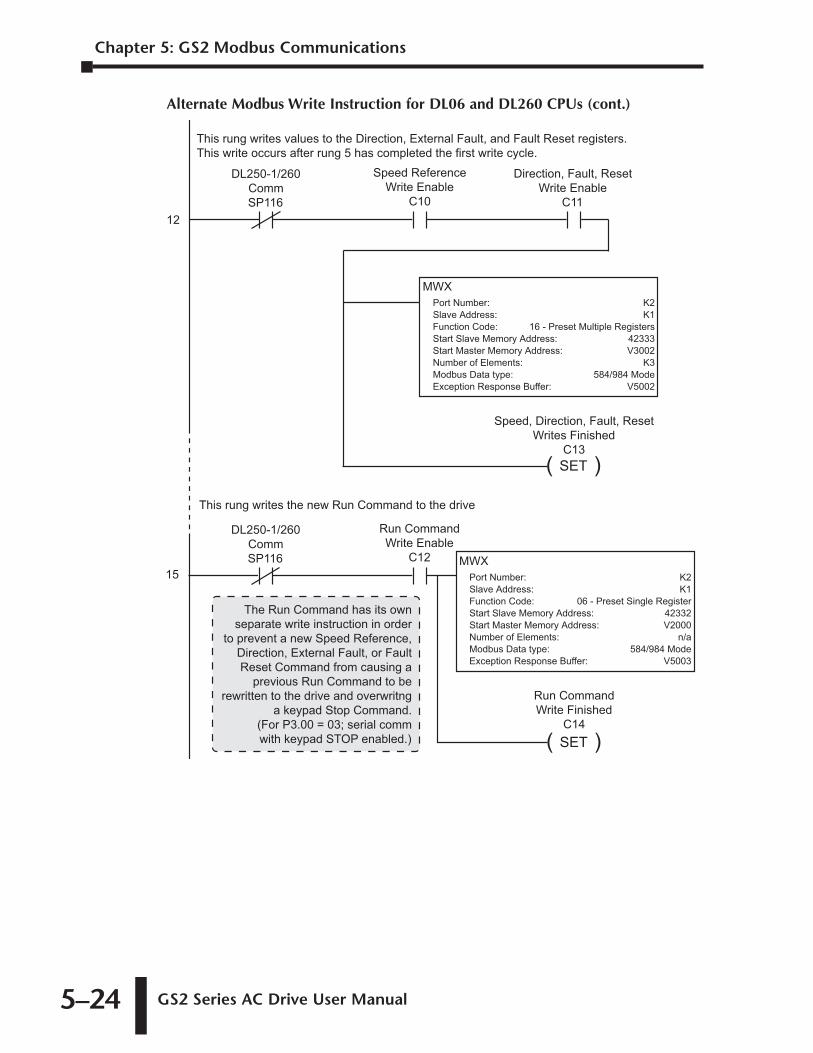
Chapter 5: GS2 Modbus Communications
GS2 Series AC Drive User Manual 5–24
Alternate Modbus Write Instruction for DL06 and DL260 CPUs (cont.)
MWXPort Number:Slave Address:Function Code:Start Slave Memory Address:Start Master Memory Address:Number of Elements:Modbus Data type:Exception Response Buffer:
K2K1
06 - Preset Single Register42332V2000
n/a584/984 Mode
V5003
12
DL250-1/260CommSP116
Speed ReferenceWrite Enable
C10
Direction, Fault, ResetWrite Enable
C11
This rung writes values to the Direction, External Fault, and Fault Reset registers.This write occurs after rung 5 has completed the first write cycle.
( )SET
Speed, Direction, Fault, ResetWrites Finished
C13
MWXPort Number:Slave Address:Function Code:Start Slave Memory Address:Start Master Memory Address:Number of Elements:Modbus Data type:Exception Response Buffer:
K2K1
16 - Preset Multiple Registers42333V3002
K3584/984 Mode
V5002
15
DL250-1/260CommSP116
Run CommandWrite Enable
C12
This rung writes the new Run Command to the drive
( )SET
Run CommandWrite Finished
C14
The Run Command has its ownseparate write instruction in order
to prevent a new Speed Reference,Direction, External Fault, or FaultReset Command from causing a
previous Run Command to berewritten to the drive and overwritng
a keypad Stop Command.(For P3.00 = 03; serial commwith keypad STOP enabled.)
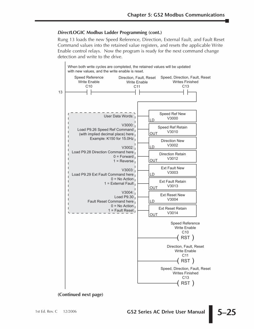
GS2 Series AC Drive User Manual 5–25
DirectLOGIC Modbus Ladder Programming (cont.)
Rung 13 loads the new Speed Reference, Direction, External Fault, and Fault ResetCommand values into the retained value registers, and resets the applicable WriteEnable control relays. Now the program is ready for the next command changedetection and write to the drive.
(Continued next page)
Speed Ref NewV3000LD
Direction RetainV3012OUT
Direction NewV3002LD
Speed Ref RetainV3010OUT
13
Speed ReferenceWrite Enable
C10
Direction, Fault, ResetWrite Enable
C11
( )RST
Speed ReferenceWrite Enable
C10
When both write cycles are completed, the retained values will be updatedwith new values, and the write enable is reset.
Ext Fault NewV3003LD
Ext Reset RetainV3014OUT
Ext Reset NewV3004LD
Ext Fault RetainV3013OUT
( )RST
Direction, Fault, ResetWrite Enable
C11
( )RST
User Data Words:
V3000:Load P9.26 Speed Ref Command(with implied decimal place) here
Example: K150 for 15.0Hz
V3002:Load P9.28 Direction Command here
0 = Forward1 = Reverse
V3003:Load P9.29 Ext Fault Command here
0 = No Action1 = External Fault
V3004:Load P9.30
Fault Reset Command here0 = No Action
1 = Fault Reset
Speed, Direction, Fault, ResetWrites Finished
C13
Speed, Direction, Fault, ResetWrites Finished
C13
Chapter 5: GS2 Modbus Communications
1st Ed. Rev. C 12/2006
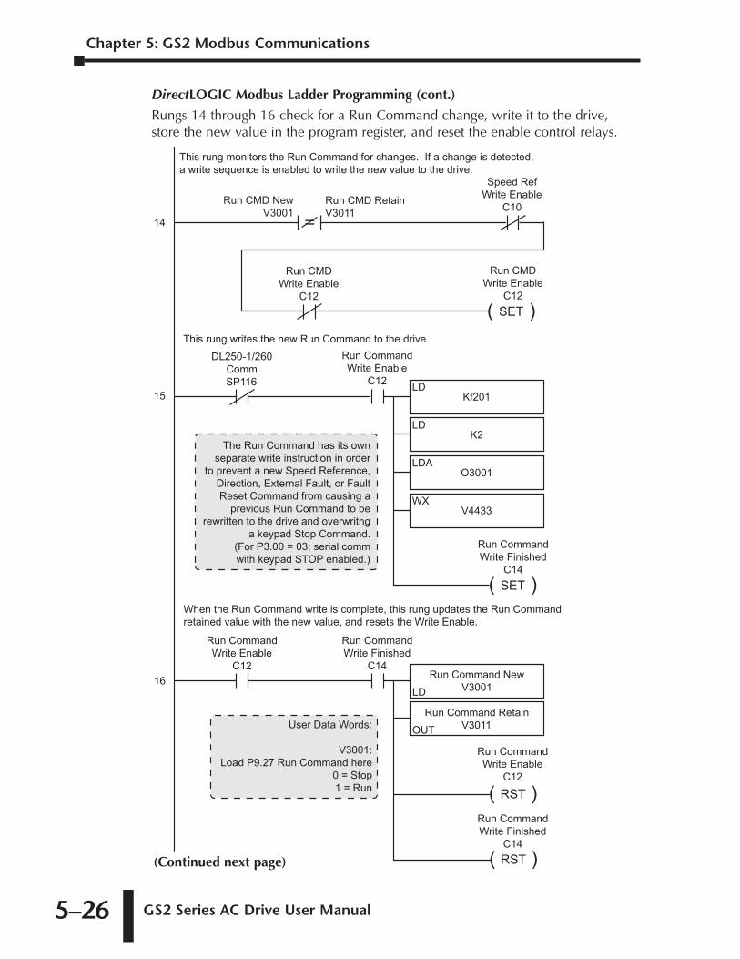
Chapter 5: GS2 Modbus Communications
GS2 Series AC Drive User Manual 5–26
DirectLOGIC Modbus Ladder Programming (cont.)
Rungs 14 through 16 check for a Run Command change, write it to the drive,store the new value in the program register, and reset the enable control relays.
Run CMD NewV3001
=Run CMD RetainV3011
Speed RefWrite Enable
C10
Run CMDWrite Enable
C12( )SET
Run CMDWrite Enable
C12
This rung monitors the Run Command for changes. If a change is detected, a write sequence is enabled to write the new value to the drive.
14
Kf201LD
V4433WX
O3001LDA
K2LD
15
DL250-1/260CommSP116
Run CommandWrite Enable
C12
This rung writes the new Run Command to the drive
Run Command NewV3001LD
Run Command RetainV3011OUT
16
Run CommandWrite Enable
C12
When the Run Command write is complete, this rung updates the Run Command retained value with the new value, and resets the Write Enable.
( )RST
Run CommandWrite Enable
C12
( )SET
Run CommandWrite Finished
C14
Run CommandWrite Finished
C14
( )RST
Run CommandWrite Finished
C14
User Data Words:
V3001:Load P9.27 Run Command here
0 = Stop1 = Run
The Run Command has its ownseparate write instruction in order
to prevent a new Speed Reference,Direction, External Fault, or FaultReset Command from causing a
previous Run Command to berewritten to the drive and overwritng
a keypad Stop Command.(For P3.00 = 03; serial commwith keypad STOP enabled.)
(Continued next page)
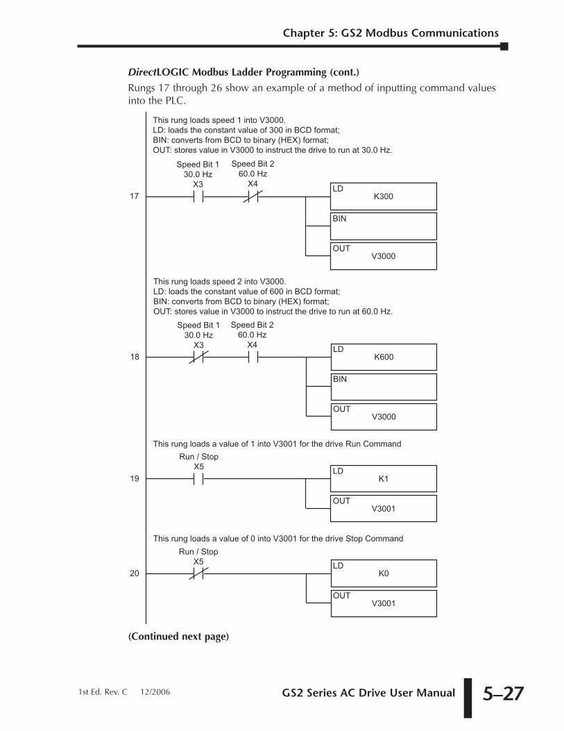
GS2 Series AC Drive User Manual 5–27
DirectLOGIC Modbus Ladder Programming (cont.)
Rungs 17 through 26 show an example of a method of inputting command valuesinto the PLC.
(Continued next page)
K300LD
V3000OUT
BIN
17
Speed Bit 130.0 Hz
X3
This rung loads speed 1 into V3000.LD: loads the constant value of 300 in BCD format;BIN: converts from BCD to binary (HEX) format;OUT: stores value in V3000 to instruct the drive to run at 30.0 Hz.
Speed Bit 260.0 Hz
X4
K600LD
V3000OUT
BIN
18
Speed Bit 260.0 Hz
X4
This rung loads speed 2 into V3000.LD: loads the constant value of 600 in BCD format;BIN: converts from BCD to binary (HEX) format;OUT: stores value in V3000 to instruct the drive to run at 60.0 Hz.
Speed Bit 130.0 Hz
X3
K1LD
V3001OUT
19
Run / StopX5
This rung loads a value of 1 into V3001 for the drive Run Command
K0LD
V3001OUT
20
This rung loads a value of 0 into V3001 for the drive Stop CommandRun / Stop
X5
Chapter 5: GS2 Modbus Communications
1st Ed. Rev. C 12/2006
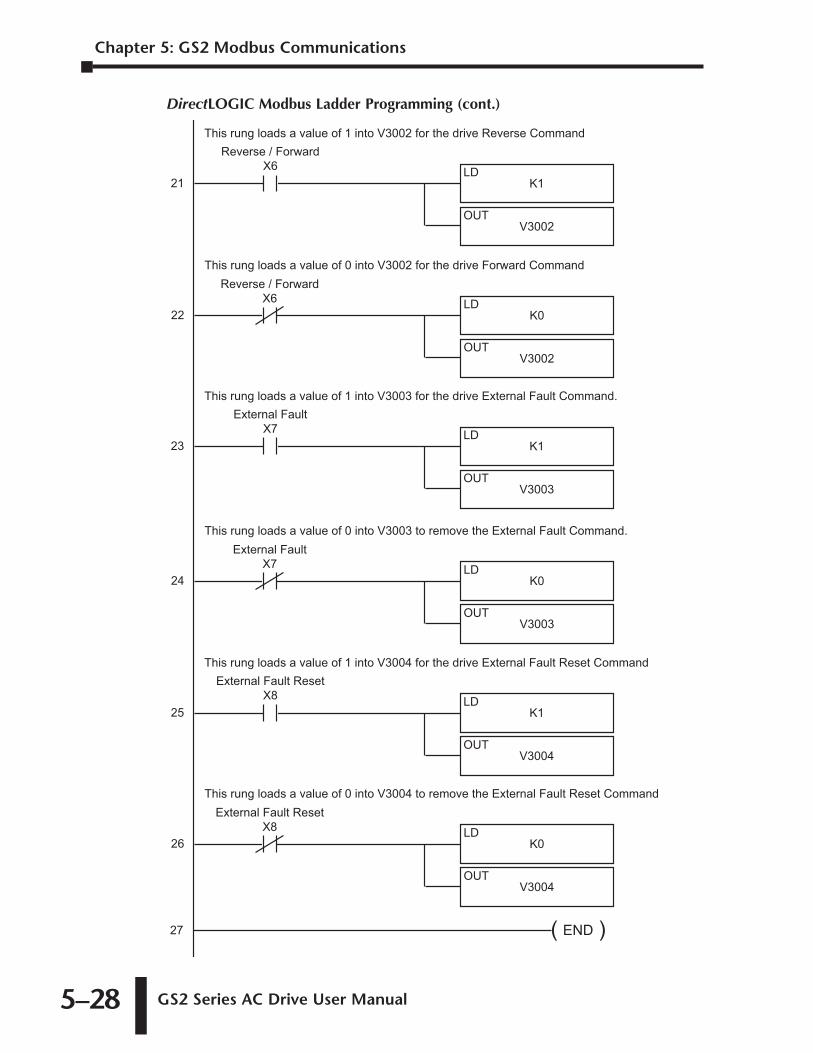
Chapter 5: GS2 Modbus Communications
GS2 Series AC Drive User Manual 5–28
DirectLOGIC Modbus Ladder Programming (cont.)
( )END27
K1LD
V3002OUT
21
Reverse / ForwardX6
This rung loads a value of 1 into V3002 for the drive Reverse Command
K0LD
V3002OUT
22
This rung loads a value of 0 into V3002 for the drive Forward CommandReverse / Forward
X6
K1LD
V3003OUT
23
External FaultX7
This rung loads a value of 1 into V3003 for the drive External Fault Command.
K0LD
V3003OUT
24
This rung loads a value of 0 into V3003 to remove the External Fault Command.External Fault
X7
K1LD
V3004OUT
25
External Fault ResetX8
This rung loads a value of 1 into V3004 for the drive External Fault Reset Command
K0LD
V3004OUT
26
This rung loads a value of 0 into V3004 to remove the External Fault Reset CommandExternal Fault Reset
X8
GS2 Series AC Drive User Manual 5–29
DirectLOGIC Modbus Ladder Programming (cont.)
Separate Run Command Write Instruction
Why do we write the Run Command with a separate write instruction? If we writethe Run Command to the drive along with the Speed Reference, Direction, ExternalFault, and Fault Reset Commands, we can keep the parameter addresses in sequence,and we can update all five of the commands with one write instruction. This methodis valid only if we disable the drive’s keypad STOP button (P3.00 = 04).
Typically, the keypad STOP button will be enabled (P3.00 = 03), and we need toprevent a change in one of the other commands from overriding a keypad StopCommand by causing a previous Run Command to be rewritten to the drive. Byusing a separate Run Command write instruction, only a deliberate Run Commandchange by the program will run the drive again after a stop.
Block Transfer Parameters
For writing to any of the parameters from P0.00 to P8.01, a group of 15 block transferparameters (P9.11 to P9.25) is available in the GS2 AC drive. This sequential block ofparameters can be used to "group" various miscellaneous non-sequential parameters,so that you can update the parameters in one programming write block instead ofhaving to use multiple WX commands.
For example: If you need to change the PID setpoint (P7.11), accel time (P1.01), andmulti-speed 1 (P5.01), this would typically take three different WX commandsbecause the parameters are non-sequential. However, by setting P9.11 to P7.11,P9.12 to P1.01, and P9.13 to P5.01, the parameters become sequential, and can becontrolled using one WX command (LD Kf201, LD K6, LDA Oxxxx, WX V4413).
Chapter 5: GS2 Modbus Communications
1st Ed. Rev. C 12/2006
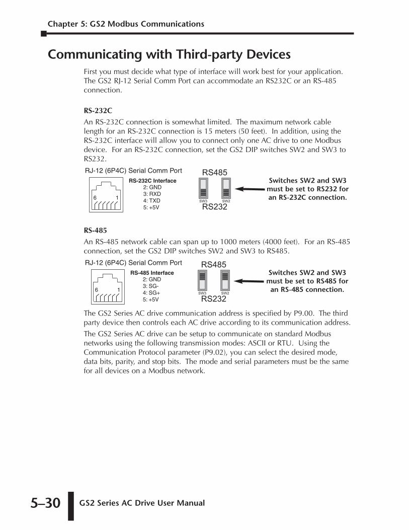
Chapter 5: GS2 Modbus Communications
GS2 Series AC Drive User Manual 5–30
Communicating with Third-party DevicesFirst you must decide what type of interface will work best for your application.The GS2 RJ-12 Serial Comm Port can accommodate an RS232C or an RS-485connection.
RS-232C
An RS-232C connection is somewhat limited. The maximum network cablelength for an RS-232C connection is 15 meters (50 feet). In addition, using theRS-232C interface will allow you to connect only one AC drive to one Modbusdevice. For an RS-232C connection, set the GS2 DIP switches SW2 and SW3 toRS232.
RS-485
An RS-485 network cable can span up to 1000 meters (4000 feet). For an RS-485connection, set the GS2 DIP switches SW2 and SW3 to RS485.
The GS2 Series AC drive communication address is specified by P9.00. The thirdparty device then controls each AC drive according to its communication address.
The GS2 Series AC drive can be setup to communicate on standard Modbusnetworks using the following transmission modes: ASCII or RTU. Using theCommunication Protocol parameter (P9.02), you can select the desired mode,data bits, parity, and stop bits. The mode and serial parameters must be the samefor all devices on a Modbus network.
RS485
RS232SW3 SW2
Switches SW2 and SW3must be set to RS485 for
an RS-485 connection.
RJ-12 (6P4C) Serial Comm Port
16
RS-485 Interface2: GND3: SG-4: SG+5: +5V
RS485
RS232SW3 SW2
Switches SW2 and SW3must be set to RS232 foran RS-232C connection.
RJ-12 (6P4C) Serial Comm Port
16
2: GND3: RXD4: TXD5: +5V
RS-232C Interface
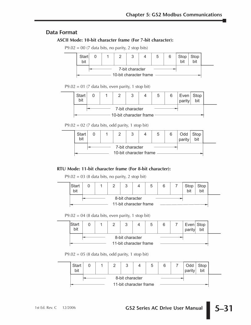
GS2 Series AC Drive User Manual 5–31
Data FormatASCII Mode: 10-bit character frame (For 7-bit character):
P9.02 = 00 (7 data bits, no parity, 2 stop bits)
P9.02 = 01 (7 data bits, even parity, 1 stop bit)
P9.02 = 02 (7 data bits, odd parity, 1 stop bit)
RTU Mode: 11-bit character frame (For 8-bit character):
P9.02 = 03 (8 data bits, no parity, 2 stop bit)
P9.02 = 04 (8 data bits, even parity, 1 stop bit)
P9.02 = 05 (8 data bits, odd parity, 1 stop bit)
Start bit
6 5 4 321 0
8-bit character11-bit character frame
Stop bit
Odd parity
7
Start bit
6 5 4 321 0
8-bit character11-bit character frame
Stop bit
Evenparity
7
Start bit
6 5 4 321 0
8-bit character11-bit character frame
Stop bit
Stop bit
7
Start bit
Stop bit
Oddparity
6 5 4 321 0
7-bit character10-bit character frame
Start bit
Stop bit
Evenparity
6 5 4 321 0
7-bit character10-bit character frame
Start bit
Stop bit
Stop bit
6 5 4 321 0
7-bit character10-bit character frame
Chapter 5: GS2 Modbus Communications
1st Ed. Rev. C 12/2006
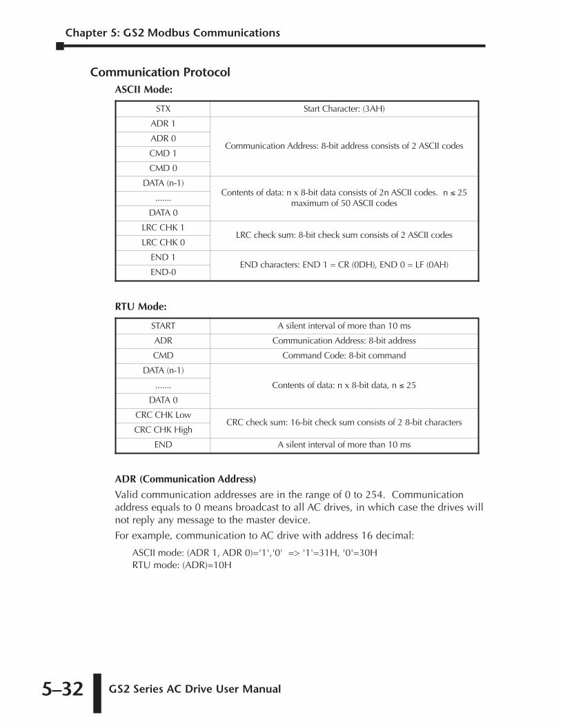
Chapter 5: GS2 Modbus Communications
GS2 Series AC Drive User Manual 5–32
Communication ProtocolASCII Mode:
RTU Mode:
ADR (Communication Address)
Valid communication addresses are in the range of 0 to 254. Communicationaddress equals to 0 means broadcast to all AC drives, in which case the drives willnot reply any message to the master device.
For example, communication to AC drive with address 16 decimal:
ASCII mode: (ADR 1, ADR 0)='1','0' => '1'=31H, '0'=30HRTU mode: (ADR)=10H
START A silent interval of more than 10 ms
ADR Communication Address: 8-bit address
CMD Command Code: 8-bit command
DATA (n-1)
Contents of data: n x 8-bit data, n ≤ 25.......
DATA 0
CRC CHK LowCRC check sum: 16-bit check sum consists of 2 8-bit characters
CRC CHK High
END A silent interval of more than 10 ms
STX Start Character: (3AH)
ADR 1
Communication Address: 8-bit address consists of 2 ASCII codesADR 0
CMD 1
CMD 0
DATA (n-1)Contents of data: n x 8-bit data consists of 2n ASCII codes. n ≤ 25
maximum of 50 ASCII codes.......
DATA 0
LRC CHK 1LRC check sum: 8-bit check sum consists of 2 ASCII codes
LRC CHK 0
END 1END characters: END 1 = CR (0DH), END 0 = LF (0AH)
END-0
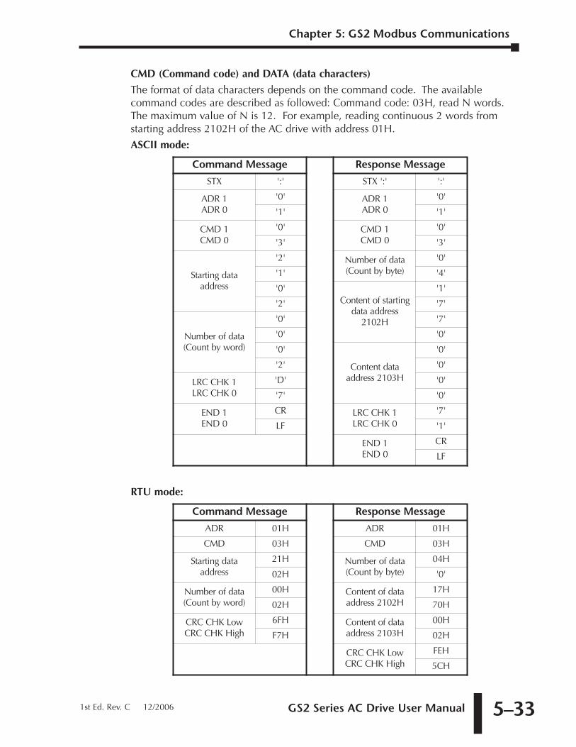
GS2 Series AC Drive User Manual 5–33
CMD (Command code) and DATA (data characters)
The format of data characters depends on the command code. The availablecommand codes are described as followed: Command code: 03H, read N words.The maximum value of N is 12. For example, reading continuous 2 words fromstarting address 2102H of the AC drive with address 01H.
ASCII mode:
RTU mode:
Command Message Response Message
ADR 01H ADR 01H
CMD 03H CMD 03H
Starting dataaddress
21H Number of data (Count by byte)
04H
02H '0'
Number of data (Count by word)
00H Content of dataaddress 2102H
17H
02H 70H
CRC CHK LowCRC CHK High
6FH Content of dataaddress 2103H
00H
F7H 02H
CRC CHK LowCRC CHK High
FEH
5CH
Command Message Response Message
STX ':' STX ':' ':'
ADR 1ADR 0
'0' ADR 1ADR 0
'0'
'1' '1'
CMD 1CMD 0
'0' CMD 1CMD 0
'0'
'3' '3'
Starting data address
'2' Number of data(Count by byte)
'0'
'1' '4'
'0'Content of starting
data address2102H
'1'
'2' '7'
Number of data(Count by word)
'0' '7'
'0' '0'
'0'
Content dataaddress 2103H
'0'
'2' '0'
LRC CHK 1LRC CHK 0
'D' '0'
'7' '0'
END 1END 0
CR LRC CHK 1LRC CHK 0
'7'
LF '1'
END 1END 0
CR
LF
Chapter 5: GS2 Modbus Communications
1st Ed. Rev. C 12/2006
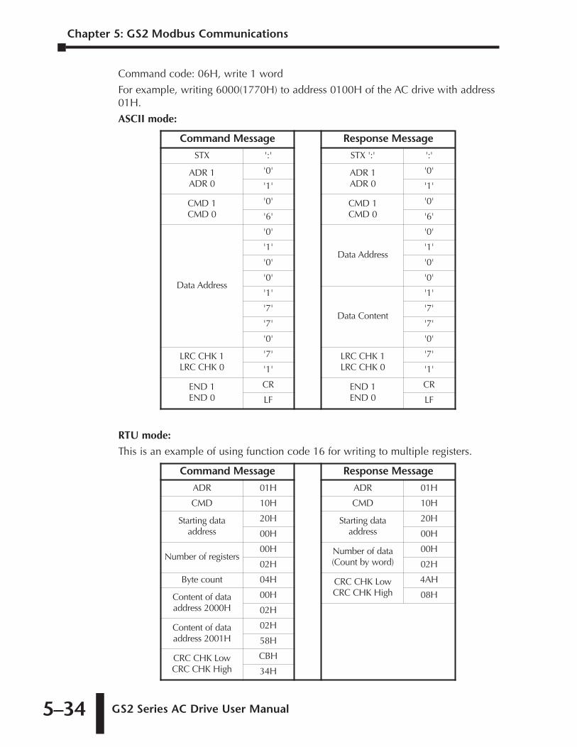
Chapter 5: GS2 Modbus Communications
GS2 Series AC Drive User Manual 5–34
Command code: 06H, write 1 word
For example, writing 6000(1770H) to address 0100H of the AC drive with address01H.
ASCII mode:
RTU mode:
This is an example of using function code 16 for writing to multiple registers.
Command Message Response Message
ADR 01H ADR 01H
CMD 10H CMD 10H
Starting dataaddress
20H Starting dataaddress
20H
00H 00H
Number of registers00H Number of data
(Count by word)00H
02H 02H
Byte count 04H CRC CHK LowCRC CHK High
4AH
Content of dataaddress 2000H
00H 08H
02H
Content of dataaddress 2001H
02H
58H
CRC CHK LowCRC CHK High
CBH
34H
Command Message Response Message
STX ':' STX ':' ':'
ADR 1ADR 0
'0' ADR 1ADR 0
'0'
'1' '1'
CMD 1CMD 0
'0' CMD 1CMD 0
'0'
'6' '6'
Data Address
'0'
Data Address
'0'
'1' '1'
'0' '0'
'0' '0'
'1'
Data Content
'1'
'7' '7'
'7' '7'
'0' '0'
LRC CHK 1LRC CHK 0
'7' LRC CHK 1LRC CHK 0
'7'
'1' '1'
END 1END 0
CR END 1END 0
CR
LF LF
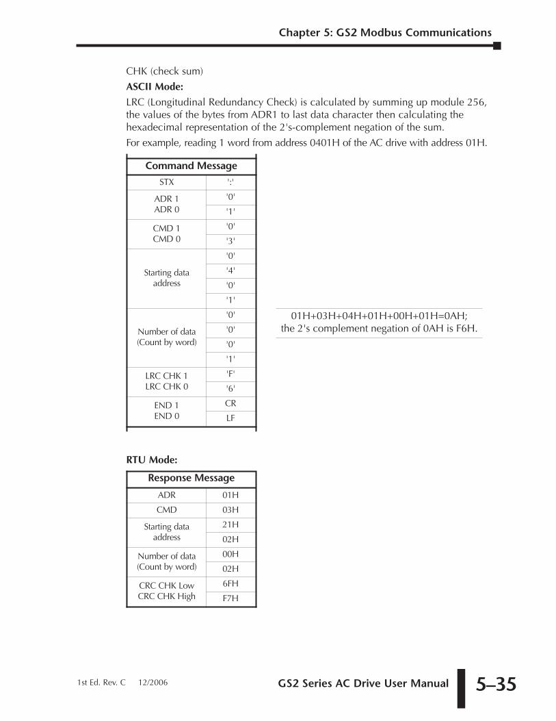
GS2 Series AC Drive User Manual 5–35
CHK (check sum)
ASCII Mode:
LRC (Longitudinal Redundancy Check) is calculated by summing up module 256,the values of the bytes from ADR1 to last data character then calculating thehexadecimal representation of the 2's-complement negation of the sum.
For example, reading 1 word from address 0401H of the AC drive with address 01H.
RTU Mode:
Response Message
ADR 01H
CMD 03H
Starting dataaddress
21H
02H
Number of data (Count by word)
00H
02H
CRC CHK LowCRC CHK High
6FH
F7H
Command Message
STX ':'
ADR 1ADR 0
'0'
'1'
CMD 1CMD 0
'0'
'3'
Starting data address
'0'
'4'
'0'
'1'
Number of data(Count by word)
'0' 01H+03H+04H+01H+00H+01H=0AH; the 2's complement negation of 0AH is F6H.'0'
'0'
'1'
LRC CHK 1LRC CHK 0
'F'
'6'
END 1END 0
CR
LF
Chapter 5: GS2 Modbus Communications
1st Ed. Rev. C 12/2006
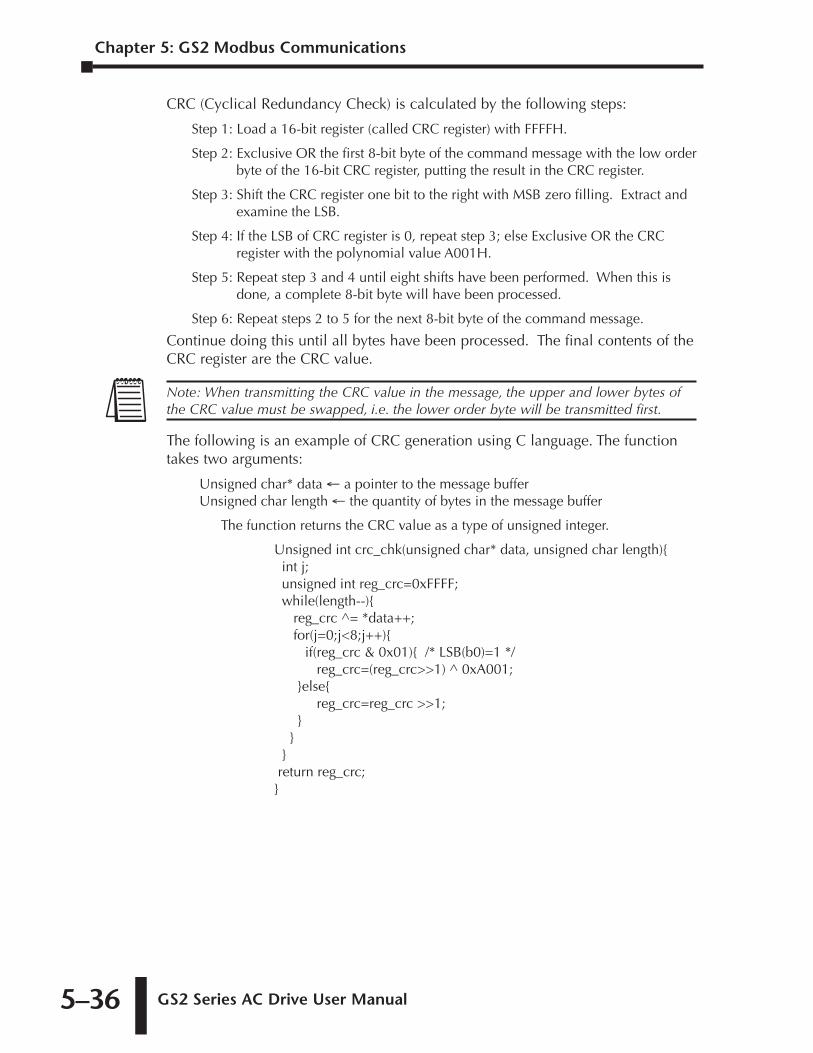
Chapter 5: GS2 Modbus Communications
GS2 Series AC Drive User Manual 5–36
CRC (Cyclical Redundancy Check) is calculated by the following steps:
Step 1: Load a 16-bit register (called CRC register) with FFFFH.
Step 2: Exclusive OR the first 8-bit byte of the command message with the low orderbyte of the 16-bit CRC register, putting the result in the CRC register.
Step 3: Shift the CRC register one bit to the right with MSB zero filling. Extract andexamine the LSB.
Step 4: If the LSB of CRC register is 0, repeat step 3; else Exclusive OR the CRCregister with the polynomial value A001H.
Step 5: Repeat step 3 and 4 until eight shifts have been performed. When this isdone, a complete 8-bit byte will have been processed.
Step 6: Repeat steps 2 to 5 for the next 8-bit byte of the command message.
Continue doing this until all bytes have been processed. The final contents of theCRC register are the CRC value.
The following is an example of CRC generation using C language. The functiontakes two arguments:
Unsigned char* data ← a pointer to the message bufferUnsigned char length ← the quantity of bytes in the message buffer
The function returns the CRC value as a type of unsigned integer.
Unsigned int crc_chk(unsigned char* data, unsigned char length){int j;unsigned int reg_crc=0xFFFF;while(length--){
reg_crc ^= *data++;for(j=0;j<8;j++){
if(reg_crc & 0x01){ /* LSB(b0)=1 */reg_crc=(reg_crc>>1) ^ 0xA001;
}else{reg_crc=reg_crc >>1;
}}
}return reg_crc;}
Note: When transmitting the CRC value in the message, the upper and lower bytes ofthe CRC value must be swapped, i.e. the lower order byte will be transmitted first.
MAINTENANCE AND
TROUBLESHOOTING 6CHAPTERCHAPTER
66CHAPTER
In This Chapter...
Maintenance and Inspection . . . . . . . . . . . . . . . . .6–2Monthly Inspection: . . . . . . . . . . . . . . . . . . . . . . . . . . . . . . . . . .6–2
Annual Inspection . . . . . . . . . . . . . . . . . . . . . . . . . . . . . . . . . . . .6–2
Troubleshooting . . . . . . . . . . . . . . . . . . . . . . . . . . .6–3Fault Codes . . . . . . . . . . . . . . . . . . . . . . . . . . . . . . . . . . . . . . . . .6–3
Warning Messages . . . . . . . . . . . . . . . . . . . . . . . . . . . . . . . . . . .6–6
Chapter 6: Maintenance and Troubleshooting
GS2 Series AC Drive User Manual6–2
Maintenance and InspectionModern AC drives are based on solid state electronics technology. Preventivemaintenance is required to operate the AC drive in its optimal condition, and toensure a long life. It is recommended that a qualified technician perform a regularinspection of the AC drive. Some items should be checked once a month, andsome items should be checked yearly. Before the inspection, always turn off theAC Input Power to the unit. Wait at least 2 minutes after all display lamps haveturned off, and then confirm that the capacitors have fully discharged bymeasuring the voltage between B1 and Frame Ground using a multimeter set tomeasure DC voltage.
Monthly Inspection:Check the following items at least once a month.
1. Make sure the motors are operating as expected.
2. Make sure the installation environment is normal.
3. Make sure the cooling system is operating as expected.
4. Check for irregular vibrations or sounds during operation.
5. Make sure the motors are not overheating during operation.
6. Check the input voltage of the AC drive and make sure the voltage is within theoperating range. Check the voltage with a voltmeter.
Annual InspectionCheck the following items once annually.
1. Tighten and reinforce the screws of the AC drive if necessary. They may loosendue to vibration or changing temperatures.
2. Make sure the conductors and insulators are not corroded and damaged.
3. Check the resistance of the insulation with mega-ohm meter.
4. Check the capacitors and relays; may require qualified repair shop to replace anydefective components. Drive components are NOT field serviceable orreplaceable.
5. Clean off any dust and dirt with a vacuum cleaner. Pay special attention tocleaning the ventilation ports, heat sinks, and PCBs. Always keep these areasclean. Accumulation of dust and dirt in these areas can cause unforeseen failures.
If the AC drive is not used for a long period of time, turn the power on at leastonce every two years and confirm that it still functions properly. To confirmfunctionality, disconnect the motor and energize the AC drive for 5 hours or morebefore attempting to run a motor with it.
WARNING! Disconnect AC power and ensure that the internal capacitors have fullydischarged before inspecting the AC drive!
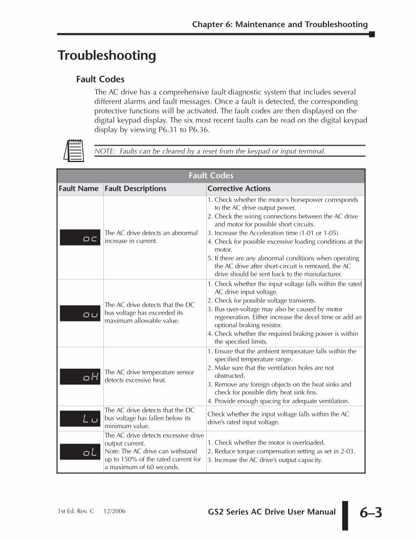
GS2 Series AC Drive User Manual 6–3
Chapter 6: Maintenance and Troubleshooting
1st Ed. Rev. C 12/2006
Troubleshooting
Fault CodesThe AC drive has a comprehensive fault diagnostic system that includes severaldifferent alarms and fault messages. Once a fault is detected, the correspondingprotective functions will be activated. The fault codes are then displayed on thedigital keypad display. The six most recent faults can be read on the digital keypaddisplay by viewing P6.31 to P6.36.
NOTE: Faults can be cleared by a reset from the keypad or input terminal.
Fault Codes
Fault Name Fault Descriptions Corrective Actions
ocThe AC drive detects an abnormalincrease in current.
1. Check whether the motor's horsepower correspondsto the AC drive output power.
2. Check the wiring connections between the AC driveand motor for possible short circuits.
3. Increase the Acceleration time (1-01 or 1-05).4. Check for possible excessive loading conditions at the
motor.5. If there are any abnormal conditions when operating
the AC drive after short-circuit is removed, the ACdrive should be sent back to the manufacturer.
ouThe AC drive detects that the DCbus voltage has exceeded itsmaximum allowable value.
1. Check whether the input voltage falls within the ratedAC drive input voltage.
2. Check for possible voltage transients.3. Bus over-voltage may also be caused by motor
regeneration. Either increase the decel time or add anoptional braking resistor.
4. Check whether the required braking power is withinthe specified limits.
oXThe AC drive temperature sensordetects excessive heat.
1. Ensure that the ambient temperature falls within thespecified temperature range.
2. Make sure that the ventilation holes are notobstructed.
3. Remove any foreign objects on the heat sinks andcheck for possible dirty heat sink fins.
4. Provide enough spacing for adequate ventilation.
LuThe AC drive detects that the DCbus voltage has fallen below itsminimum value.
Check whether the input voltage falls within the ACdrive’s rated input voltage.
oL
The AC drive detects excessive driveoutput current. Note: The AC drive can withstandup to 150% of the rated current fora maximum of 60 seconds.
1. Check whether the motor is overloaded.2. Reduce torque compensation setting as set in 2-03.3. Increase the AC drive’s output capacity.
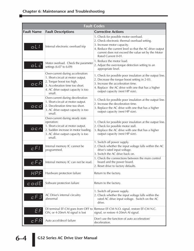
Chapter 6: Maintenance and Troubleshooting
GS2 Series AC Drive User Manual6–4
Fault CodesFault Name Fault Descriptions Corrective Actions
oL1 Internal electronic overload trip
1. Check for possible motor overload.2. Check electronic thermal overload setting.3. Increase motor capacity.4. Reduce the current level so that the AC drive output
current does not exceed the value set by the MotorRated Current 0-01.
oL2Motor overload. Check the parametersettings (6-07 to 6-09)
1. Reduce the motor load.2. Adjust the over-torque detection setting to an
appropriate level.
ocA
Over-current during acceleration: 1. Short-circuit at motor output. 2. Torque boost too high. 3. Acceleration time too short. 4. AC drive output capacity is too
small.
1. Check for possible poor insulation at the output line.2. Decrease the torque boost setting in 2-03.3. Increase the acceleration time.4. Replace the AC drive with one that has a higher
output capacity (next HP size).
ocd
Over-current during deceleration1. Short-circuit at motor output. 2. Deceleration time too short. 3. AC drive output capacity is too
small.
1. Check for possible poor insulation at the output line.2. Increase the deceleration time.3. Replace the AC drive with one that has a higher
output capacity (next HP size).
ocn
Over-current during steady stateoperation: 1. Short-circuit at motor output. 2. Sudden increase in motor loading. 3. AC drive output capacity is too
small.
1. Check for possible poor insulation at the output line.2. Check for possible motor stall.3. Replace the AC drive with one that has a higher
output capacity (next HP size).
cF1Internal memory IC cannot beprogrammed.
1. Switch off power supply.2. Check whether the input voltage falls within the AC
drive's rated input voltage.3. Switch the AC drive back on.
cF2 Internal memory IC can not be read.1. Check the connections between the main control
board and the power board.2. Reset drive to factory defaults.
XPF Hardware protection failure Return to the factory.
codE Software protection failure Return to the factory.
cF3AC Drive’s internal circuitryabnormal
1. Switch off power supply.2. Check whether the input voltage falls within the
rated AC drive input voltage. Switch on the ACdrive.
EFDI terminal EF-CM goes from OFF toON, or 4-20mA AI signal is lost
Remove EF-CM N.O. signal, restore EF-CM N.C.signal, or restore 4-20mA AI signal.
cFA Auto accel/decel failureDon’t use the function of auto acceleration/deceleration.
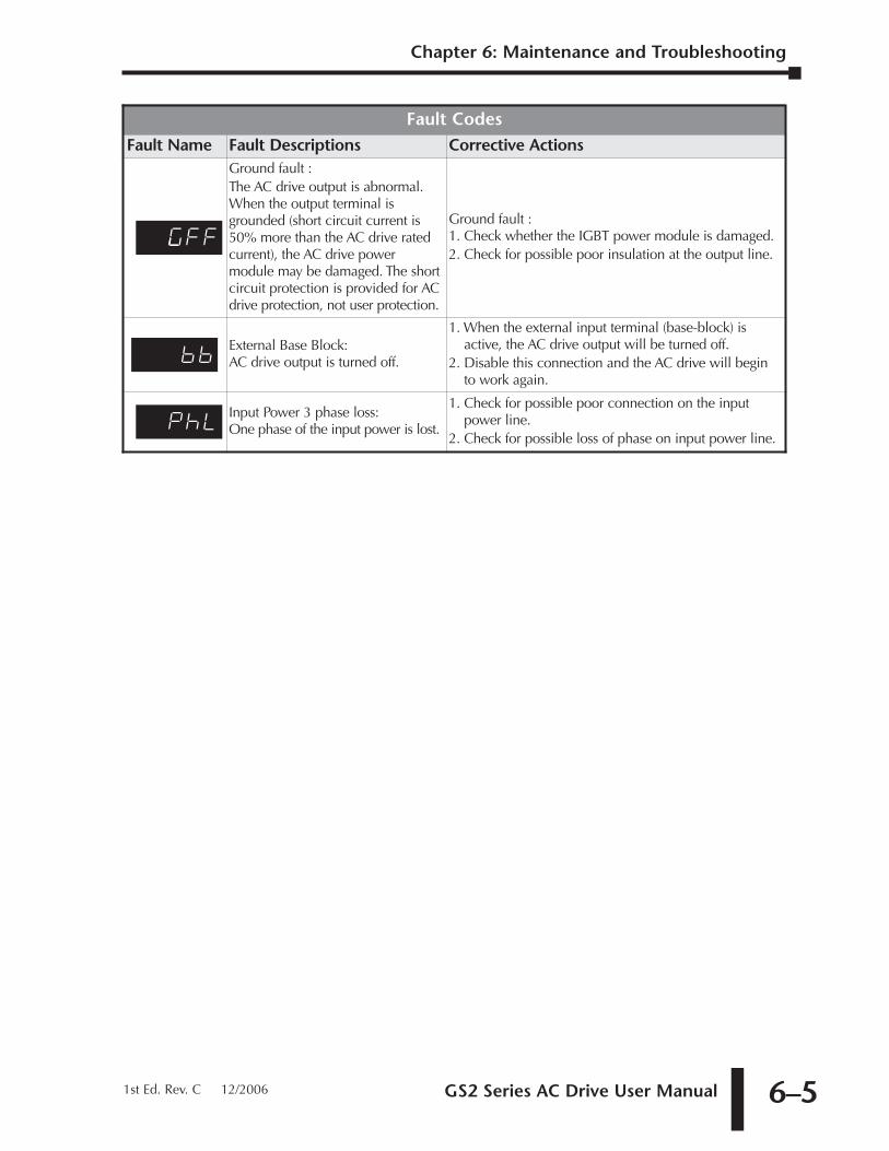
GS2 Series AC Drive User Manual 6–5
Chapter 6: Maintenance and Troubleshooting
1st Ed. Rev. C 12/2006
Fault CodesFault Name Fault Descriptions Corrective Actions
CuFF
Ground fault : The AC drive output is abnormal.When the output terminal isgrounded (short circuit current is50% more than the AC drive ratedcurrent), the AC drive powermodule may be damaged. The shortcircuit protection is provided for ACdrive protection, not user protection.
Ground fault : 1. Check whether the IGBT power module is damaged.2. Check for possible poor insulation at the output line.
bbExternal Base Block:AC drive output is turned off.
1. When the external input terminal (base-block) isactive, the AC drive output will be turned off.
2. Disable this connection and the AC drive will beginto work again.
PHLInput Power 3 phase loss:One phase of the input power is lost.
1. Check for possible poor connection on the inputpower line.
2. Check for possible loss of phase on input power line.
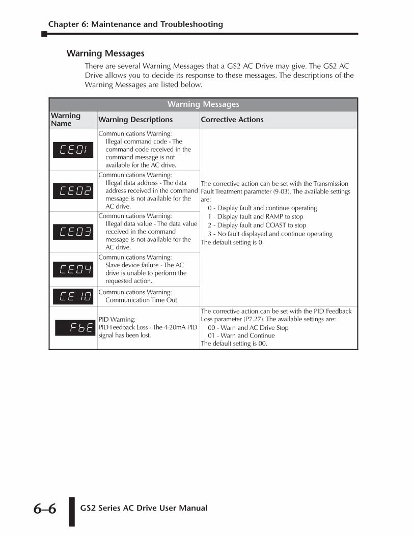
Chapter 6: Maintenance and Troubleshooting
GS2 Series AC Drive User Manual6–6
Warning MessagesThere are several Warning Messages that a GS2 AC Drive may give. The GS2 ACDrive allows you to decide its response to these messages. The descriptions of theWarning Messages are listed below.
Warning MessagesWarningName Warning Descriptions Corrective Actions
Ce01
Communications Warning:Illegal command code - Thecommand code received in thecommand message is notavailable for the AC drive.
The corrective action can be set with the TransmissionFault Treatment parameter (9-03). The available settingsare:
0 - Display fault and continue operating1 - Display fault and RAMP to stop2 - Display fault and COAST to stop3 - No fault displayed and continue operating
The default setting is 0.
Ce02
Communications Warning:Illegal data address - The dataaddress received in the commandmessage is not available for theAC drive.
Ce03
Communications Warning:Illegal data value - The data valuereceived in the commandmessage is not available for theAC drive.
Ce04
Communications Warning:Slave device failure - The ACdrive is unable to perform therequested action.
Ce!0Communications Warning:
Communication Time Out
FbEPID Warning:PID Feedback Loss - The 4-20mA PIDsignal has been lost.
The corrective action can be set with the PID FeedbackLoss parameter (P7.27). The available settings are:
00 - Warn and AC Drive Stop01 - Warn and Continue
The default setting is 00.
ACCESSORIES AAPPENDIXAPPENDIX
AAAPPENDIX
In This Appendix...
Accessories Part Numbering . . . . . . . . . . . . . . . . . . . . . . . . . .A–2
Line Reactors . . . . . . . . . . . . . . . . . . . . . . . . . . . . . . . . . . . . .A–2Line Reactor Dimensions . . . . . . . . . . . . . . . . . . . . . . . . . . . . . . .A–4Line Reactor Applications and Connections . . . . . . . . . . . . . . . . .A–5
Braking Resistors . . . . . . . . . . . . . . . . . . . . . . . . . . . . . . . . . . .A–8Braking Resistor Connections . . . . . . . . . . . . . . . . . . . . . . . . . . .A–8Braking Resistor Dimensions . . . . . . . . . . . . . . . . . . . . . . . . . . . .A–9
EMI Input Filters . . . . . . . . . . . . . . . . . . . . . . . . . . . . . . . . . .A–10EMI Filter Dimensions . . . . . . . . . . . . . . . . . . . . . . . . . . . . . . . .A–11EMI Filter Connections . . . . . . . . . . . . . . . . . . . . . . . . . . . . . . .A–15
RF Filters . . . . . . . . . . . . . . . . . . . . . . . . . . . . . . . . . . . . . . . .A–16
Fuses and Fuse Kits . . . . . . . . . . . . . . . . . . . . . . . . . . . . . . . .A–17Fuses and Fuse Kits Dimensions . . . . . . . . . . . . . . . . . . . . . . . .A–18
GS-EDRV Ethernet Interface . . . . . . . . . . . . . . . . . . . . . . . . .A–20
GS Drive Configuration Software . . . . . . . . . . . . . . . . . . . . .A–22System Requirements . . . . . . . . . . . . . . . . . . . . . . . . . . . . . . . .A–22Software Configuration Methods . . . . . . . . . . . . . . . . . . . . . . .A–22
Miscellaneous Accessories . . . . . . . . . . . . . . . . . . . . . . . . . . .A–25Configuration Cable . . . . . . . . . . . . . . . . . . . . . . . . . . . . . . . . .A–25Spare Keypad . . . . . . . . . . . . . . . . . . . . . . . . . . . . . . . . . . . . . .A–25Keypad Cables . . . . . . . . . . . . . . . . . . . . . . . . . . . . . . . . . . . . .A–25Communication Distribution Blocks . . . . . . . . . . . . . . . . . . . . .A–26
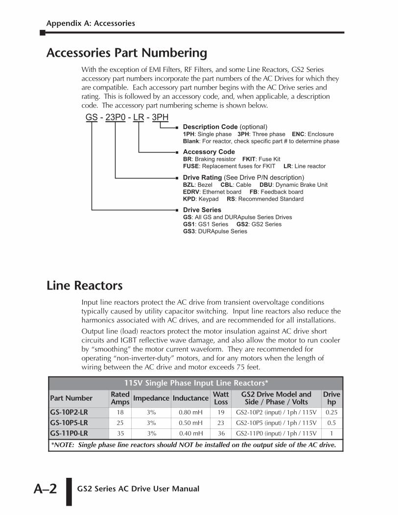
Appendix A: Accessories
GS2 Series AC Drive User ManualA–2
Accessories Part NumberingWith the exception of EMI Filters, RF Filters, and some Line Reactors, GS2 Seriesaccessory part numbers incorporate the part numbers of the AC Drives for which theyare compatible. Each accessory part number begins with the AC Drive series andrating. This is followed by an accessory code, and, when applicable, a descriptioncode. The accessory part numbering scheme is shown below.
Line ReactorsInput line reactors protect the AC drive from transient overvoltage conditionstypically caused by utility capacitor switching. Input line reactors also reduce theharmonics associated with AC drives, and are recommended for all installations.
Output line (load) reactors protect the motor insulation against AC drive shortcircuits and IGBT reflective wave damage, and also allow the motor to run coolerby “smoothing” the motor current waveform. They are recommended foroperating “non-inverter-duty” motors, and for any motors when the length ofwiring between the AC drive and motor exceeds 75 feet.
115V Single Phase Input Line Reactors*
Part Number RatedAmps Impedance Inductance Watt
LossGS2 Drive Model and Side / Phase / Volts
Drivehp
GS-10P2-LR 18 3% 0.80 mH 19 GS2-10P2 (input) / 1ph / 115V 0.25
GS-10P5-LR 25 3% 0.50 mH 23 GS2-10P5 (input) / 1ph / 115V 0.5
GS-11P0-LR 35 3% 0.40 mH 36 GS2-11P0 (input) / 1ph / 115V 1
*NOTE: Single phase line reactors should NOT be installed on the output side of the AC drive.
GS - 23P0 - LR - 3PH
Drive SeriesGS: All GS and DURApulse Series DrivesGS1: GS1 Series GS2: GS2 SeriesGS3: DURApulse Series
Description Code (optional)1PH: Single phase 3PH: Three phase ENC: EnclosureBlank: For reactor, check specific part # to determine phase
Accessory CodeBR: Braking resistor FKIT: Fuse KitFUSE: Replacement fuses for FKIT LR: Line reactor
Drive Rating (See Drive P/N description)BZL: Bezel CBL: Cable DBU: Dynamic Brake UnitEDRV: Ethernet board FB: Feedback boardKPD: Keypad RS: Recommended Standard
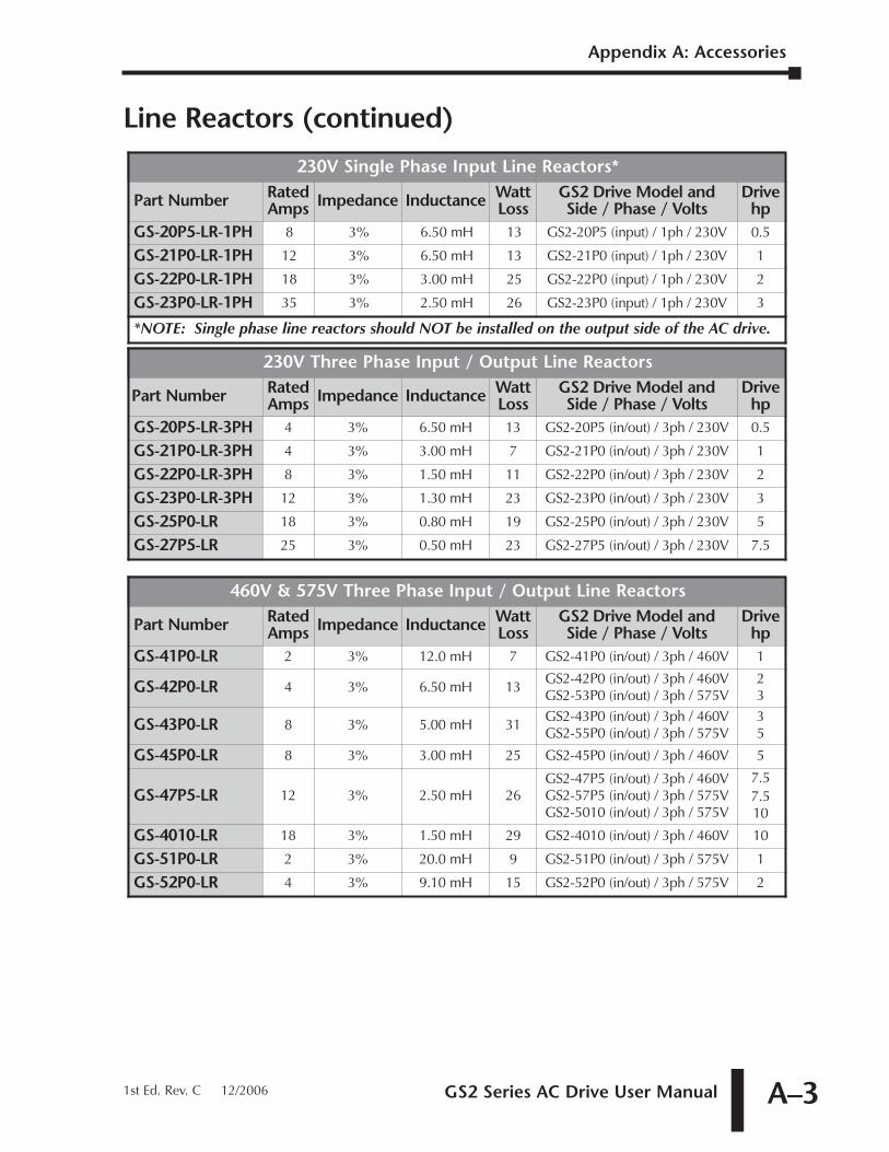
GS2 Series AC Drive User Manual A–3
Line Reactors (continued)
460V & 575V Three Phase Input / Output Line Reactors
Part Number RatedAmps Impedance Inductance Watt
LossGS2 Drive Model and Side / Phase / Volts
Drivehp
GS-41P0-LR 2 3% 12.0 mH 7 GS2-41P0 (in/out) / 3ph / 460V 1
GS-42P0-LR 4 3% 6.50 mH 13GS2-42P0 (in/out) / 3ph / 460VGS2-53P0 (in/out) / 3ph / 575V
23
GS-43P0-LR 8 3% 5.00 mH 31GS2-43P0 (in/out) / 3ph / 460VGS2-55P0 (in/out) / 3ph / 575V
35
GS-45P0-LR 8 3% 3.00 mH 25 GS2-45P0 (in/out) / 3ph / 460V 5
GS-47P5-LR 12 3% 2.50 mH 26GS2-47P5 (in/out) / 3ph / 460VGS2-57P5 (in/out) / 3ph / 575VGS2-5010 (in/out) / 3ph / 575V
7.57.510
GS-4010-LR 18 3% 1.50 mH 29 GS2-4010 (in/out) / 3ph / 460V 10
GS-51P0-LR 2 3% 20.0 mH 9 GS2-51P0 (in/out) / 3ph / 575V 1
GS-52P0-LR 4 3% 9.10 mH 15 GS2-52P0 (in/out) / 3ph / 575V 2
230V Three Phase Input / Output Line Reactors
Part Number RatedAmps Impedance Inductance Watt
LossGS2 Drive Model and Side / Phase / Volts
Drivehp
GS-20P5-LR-3PH 4 3% 6.50 mH 13 GS2-20P5 (in/out) / 3ph / 230V 0.5
GS-21P0-LR-3PH 4 3% 3.00 mH 7 GS2-21P0 (in/out) / 3ph / 230V 1
GS-22P0-LR-3PH 8 3% 1.50 mH 11 GS2-22P0 (in/out) / 3ph / 230V 2
GS-23P0-LR-3PH 12 3% 1.30 mH 23 GS2-23P0 (in/out) / 3ph / 230V 3
GS-25P0-LR 18 3% 0.80 mH 19 GS2-25P0 (in/out) / 3ph / 230V 5
GS-27P5-LR 25 3% 0.50 mH 23 GS2-27P5 (in/out) / 3ph / 230V 7.5
230V Single Phase Input Line Reactors*
Part Number RatedAmps Impedance Inductance Watt
LossGS2 Drive Model and Side / Phase / Volts
Drivehp
GS-20P5-LR-1PH 8 3% 6.50 mH 13 GS2-20P5 (input) / 1ph / 230V 0.5
GS-21P0-LR-1PH 12 3% 6.50 mH 13 GS2-21P0 (input) / 1ph / 230V 1
GS-22P0-LR-1PH 18 3% 3.00 mH 25 GS2-22P0 (input) / 1ph / 230V 2
GS-23P0-LR-1PH 35 3% 2.50 mH 26 GS2-23P0 (input) / 1ph / 230V 3
*NOTE: Single phase line reactors should NOT be installed on the output side of the AC drive.
Appendix A: Accessories
1st Ed. Rev. C 12/2006
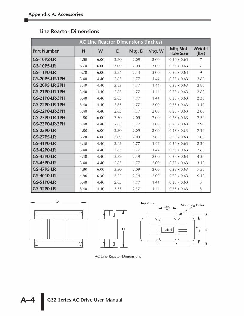
Appendix A: Accessories
GS2 Series AC Drive User ManualA–4
Line Reactor Dimensions
AC Line Reactor Dimensions
LabelH
Top ViewMounting Holes
WMTG
W
MTGD D
AC Line Reactor Dimensions (inches)
Part Number H W D Mtg. D Mtg. W Mtg SlotHole Size
Weight(lbs)
GS-10P2-LR 4.80 6.00 3.30 2.09 2.00 0.28 x 0.63 7
GS-10P5-LR 5.70 6.00 3.09 2.09 3.00 0.28 x 0.63 7
GS-11P0-LR 5.70 6.00 3.34 2.34 3.00 0.28 x 0.63 9
GS-20P5-LR-1PH 3.40 4.40 2.83 1.77 1.44 0.28 x 0.63 2.80
GS-20P5-LR-3PH 3.40 4.40 2.83 1.77 1.44 0.28 x 0.63 2.80
GS-21P0-LR-1PH 3.40 4.40 2.83 1.77 1.44 0.28 x 0.63 2.80
GS-21P0-LR-3PH 3.40 4.40 2.83 1.77 1.44 0.28 x 0.63 2.30
GS-22P0-LR-1PH 3.40 4.40 2.83 1.77 2.00 0.28 x 0.63 3.10
GS-22P0-LR-3PH 3.40 4.40 2.83 1.77 2.00 0.28 x 0.63 2.80
GS-23P0-LR-1PH 4.80 6.00 3.30 2.09 2.00 0.28 x 0.63 7.50
GS-23P0-LR-3PH 3.40 4.40 2.83 1.77 2.00 0.28 x 0.63 2.90
GS-25P0-LR 4.80 6.00 3.30 2.09 2.00 0.28 x 0.63 7.10
GS-27P5-LR 5.70 6.00 3.09 2.09 3.00 0.28 x 0.63 7.00
GS-41P0-LR 3.40 4.40 2.83 1.77 1.44 0.28 x 0.63 2.30
GS-42P0-LR 3.40 4.40 2.83 1.77 1.44 0.28 x 0.63 2.80
GS-43P0-LR 3.40 4.40 3.39 2.39 2.00 0.28 x 0.63 4.30
GS-45P0-LR 3.40 4.40 2.83 1.77 2.00 0.28 x 0.63 3.10
GS-47P5-LR 4.80 6.00 3.30 2.09 2.00 0.28 x 0.63 7.50
GS-4010-LR 4.80 6.30 3.55 2.34 2.00 0.28 x 0.63 9.10
GS-51P0-LR 3.40 4.40 2.83 1.77 1.44 0.28 x 0.63 3
GS-52P0-LR 3.40 4.40 3.33 2.37 1.44 0.28 x 0.63 3
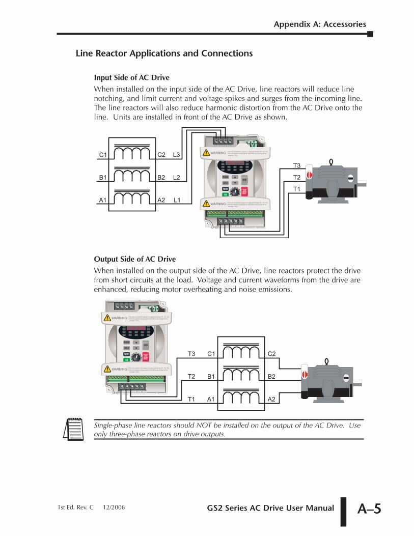
GS2 Series AC Drive User Manual A–5
Line Reactor Applications and Connections
Input Side of AC Drive
When installed on the input side of the AC Drive, line reactors will reduce linenotching, and limit current and voltage spikes and surges from the incoming line.The line reactors will also reduce harmonic distortion from the AC Drive onto theline. Units are installed in front of the AC Drive as shown.
Output Side of AC Drive
When installed on the output side of the AC Drive, line reactors protect the drivefrom short circuits at the load. Voltage and current waveforms from the drive areenhanced, reducing motor overheating and noise emissions.
Single-phase line reactors should NOT be installed on the output of the AC Drive. Useonly three-phase reactors on drive outputs.
C1
T1
T2
T3
A2
B2
C2
A1
B1
C1
L2
T1
T2
T3
A2
B2
C2
A1 L1
B1
L3
Appendix A: Accessories
1st Ed. Rev. C 12/2006
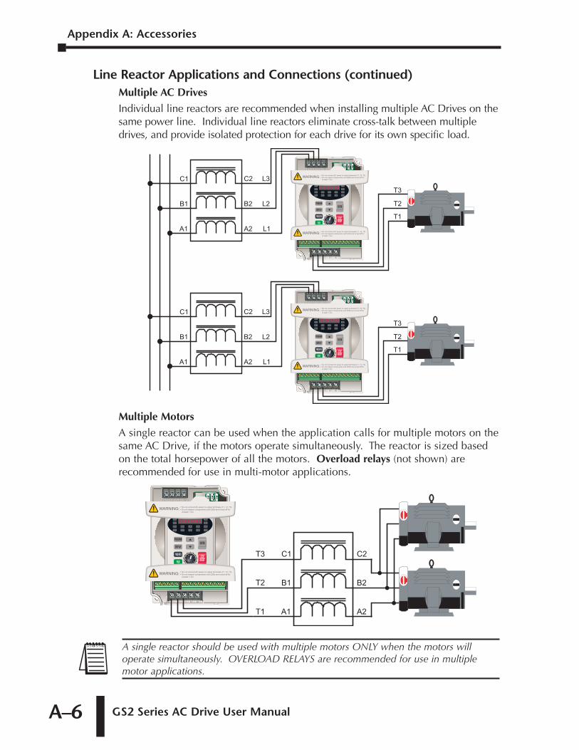
Appendix A: Accessories
GS2 Series AC Drive User ManualA–6
Line Reactor Applications and Connections (continued)Multiple AC Drives
Individual line reactors are recommended when installing multiple AC Drives on thesame power line. Individual line reactors eliminate cross-talk between multipledrives, and provide isolated protection for each drive for its own specific load.
Multiple Motors
A single reactor can be used when the application calls for multiple motors on thesame AC Drive, if the motors operate simultaneously. The reactor is sized basedon the total horsepower of all the motors. Overload relays (not shown) arerecommended for use in multi-motor applications.
A single reactor should be used with multiple motors ONLY when the motors willoperate simultaneously. OVERLOAD RELAYS are recommended for use in multiplemotor applications.
C1
T1
T2
T3
A2
B2
C2
A1
B1
C1
L2
T1
T2
T3
A2
B2
C2
A1 L1
B1
L3
C1
L2
T1
T2
T3
A2
B2
C2
A1 L1
B1
L3
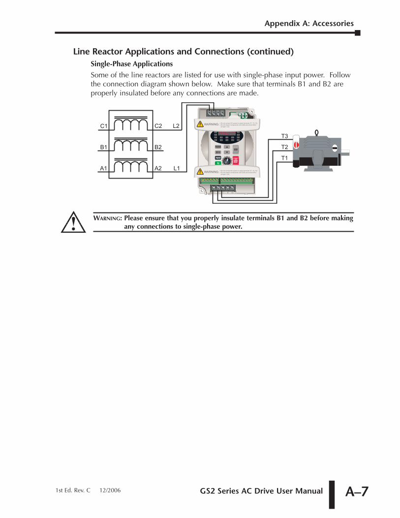
GS2 Series AC Drive User Manual A–7
Line Reactor Applications and Connections (continued)Single-Phase Applications
Some of the line reactors are listed for use with single-phase input power. Followthe connection diagram shown below. Make sure that terminals B1 and B2 areproperly insulated before any connections are made.
WARNING: Please ensure that you properly insulate terminals B1 and B2 before makingany connections to single-phase power.
C1
T1
T2
T3
A2
B2
C2
A1 L1
B1
L2
Appendix A: Accessories
1st Ed. Rev. C 12/2006
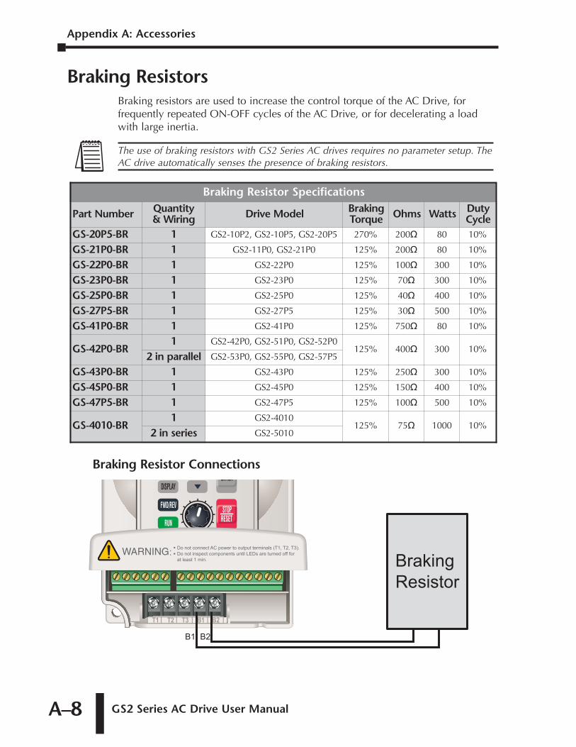
Appendix A: Accessories
GS2 Series AC Drive User ManualA–8
Braking ResistorsBraking resistors are used to increase the control torque of the AC Drive, forfrequently repeated ON-OFF cycles of the AC Drive, or for decelerating a loadwith large inertia.
Braking Resistor Connections
B2B1
Braking
Resistor
Braking Resistor Specifications
Part Number Quantity& Wiring Drive Model Braking
Torque Ohms Watts DutyCycle
GS-20P5-BR 1 GS2-10P2, GS2-10P5, GS2-20P5 270% 200� 80 10%
GS-21P0-BR 1 GS2-11P0, GS2-21P0 125% 200� 80 10%
GS-22P0-BR 1 GS2-22P0 125% 100� 300 10%
GS-23P0-BR 1 GS2-23P0 125% 70� 300 10%
GS-25P0-BR 1 GS2-25P0 125% 40� 400 10%
GS-27P5-BR 1 GS2-27P5 125% 30� 500 10%
GS-41P0-BR 1 GS2-41P0 125% 750� 80 10%
GS-42P0-BR1 GS2-42P0, GS2-51P0, GS2-52P0
125% 400� 300 10%2 in parallel GS2-53P0, GS2-55P0, GS2-57P5
GS-43P0-BR 1 GS2-43P0 125% 250� 300 10%
GS-45P0-BR 1 GS2-45P0 125% 150� 400 10%
GS-47P5-BR 1 GS2-47P5 125% 100� 500 10%
GS-4010-BR1 GS2-4010
125% 75� 1000 10%2 in series GS2-5010
The use of braking resistors with GS2 Series AC drives requires no parameter setup. TheAC drive automatically senses the presence of braking resistors.
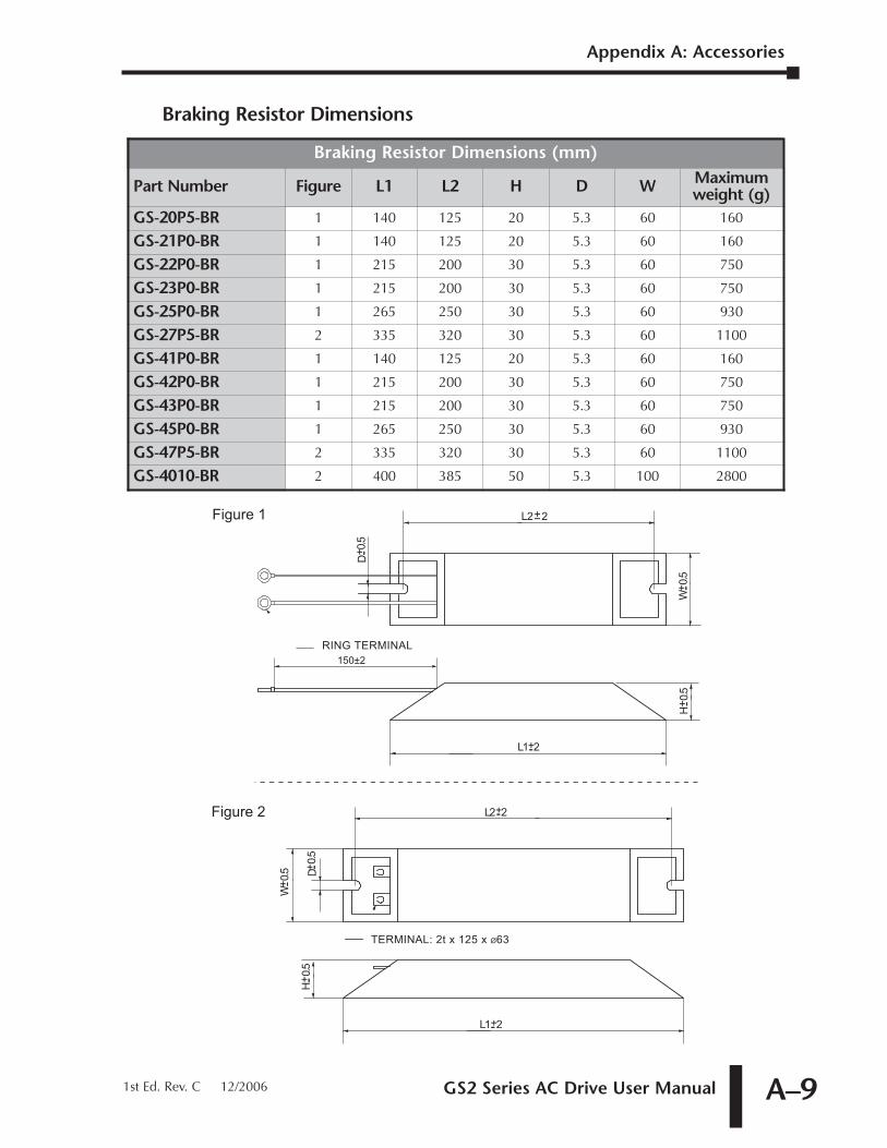
GS2 Series AC Drive User Manual A–9
Braking Resistor Dimensions
W+ --0
.5 D
L2+--2
+ --0.5
L1+--2
H+ --0
.5
W+ --0
.5
D
L2+--2
+ --0.5
L1+--2
H+ --0
.5
RING TERMINAL
TERMINAL: 2t x 125 x Ø63
Figure 1
Figure 2
150±2
Braking Resistor Dimensions (mm)
Part Number Figure L1 L2 H D W Maximumweight (g)
GS-20P5-BR 1 140 125 20 5.3 60 160
GS-21P0-BR 1 140 125 20 5.3 60 160
GS-22P0-BR 1 215 200 30 5.3 60 750
GS-23P0-BR 1 215 200 30 5.3 60 750
GS-25P0-BR 1 265 250 30 5.3 60 930
GS-27P5-BR 2 335 320 30 5.3 60 1100
GS-41P0-BR 1 140 125 20 5.3 60 160
GS-42P0-BR 1 215 200 30 5.3 60 750
GS-43P0-BR 1 215 200 30 5.3 60 750
GS-45P0-BR 1 265 250 30 5.3 60 930
GS-47P5-BR 2 335 320 30 5.3 60 1100
GS-4010-BR 2 400 385 50 5.3 100 2800
Appendix A: Accessories
1st Ed. Rev. C 12/2006
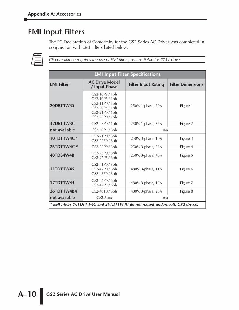
Appendix A: Accessories
GS2 Series AC Drive User ManualA–10
EMI Input FiltersThe EC Declaration of Conformity for the GS2 Series AC Drives was completed inconjunction with EMI Filters listed below.
EMI Input Filter Specifications
EMI Filter AC Drive Model/ Input Phase Filter Input Rating Filter Dimensions
20DRT1W3S
GS2-10P2 / 1phGS2-10P5 / 1phGS2-11P0 / 1phGS2-20P5 / 1phGS2-21P0 / 1phGS2-22P0 / 1ph
250V, 1-phase, 20A Figure 1
32DRT1W3C GS2-23P0 / 1ph 250V, 1-phase, 32A Figure 2
not available GS2-20P5 / 3ph n/a
10TDT1W4C * GS2-21P0 / 3phGS2-22P0 / 3ph
250V, 3-phase, 10A Figure 3
26TDT1W4C * GS2-23P0 / 3ph 250V, 3-phase, 26A Figure 4
40TDS4W4B GS2-25P0 / 3phGS2-27P5 / 3ph
250V, 3-phase, 40A Figure 5
11TDT1W4SGS2-41P0 / 3phGS2-42P0 / 3phGS2-43P0 / 3ph
480V, 3-phase, 11A Figure 6
17TDT1W44 GS2-45P0 / 3phGS2-47P5 / 3ph
480V, 3-phase, 17A Figure 7
26TDT1W4B4 GS2-4010 / 3ph 480V, 3-phase, 26A Figure 8
not available GS2-5xxx n/a
* EMI filters 10TDT1W4C and 26TDT1W4C do not mount underneath GS2 drives.
CE compliance requires the use of EMI filters; not available for 575V drives.
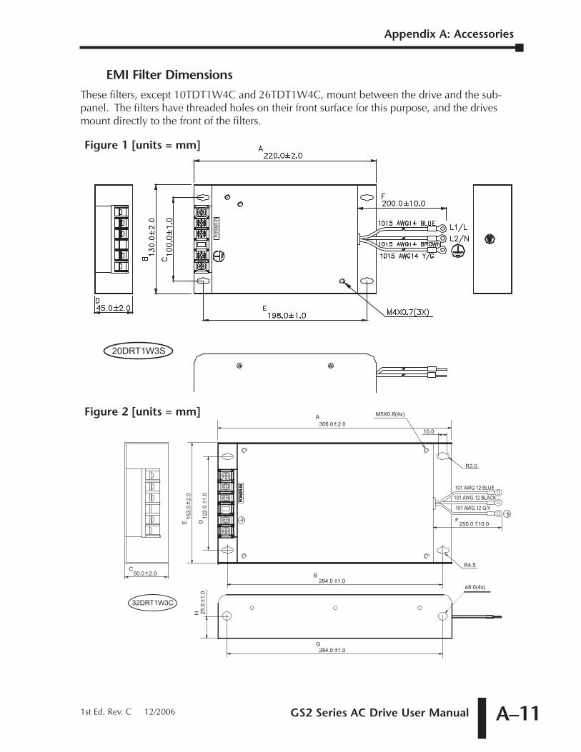
GS2 Series AC Drive User Manual A–11
EMI Filter DimensionsThese filters, except 10TDT1W4C and 26TDT1W4C, mount between the drive and the sub-panel. The filters have threaded holes on their front surface for this purpose, and the drivesmount directly to the front of the filters.
101 AWG 12 BLUE
101 AWG 12 BLACK
101 AWG 12 G/Y
POW
ER-IN
POW
ER-IN
C50.0 2.0+_
E D
B
G
A
F
H
250.0 10.0+_
25.0
1.
0+_
306.0 2.0+_
122.
0 1
.0+_
153.
0 2
.0+_
284.0 1.0+_
o8.0(4x)284.0 1.0+_
R4.5
M5X0.8(4x)
10.0
R3.0
32DRT1W3C
Figure 2 [units = mm]
PO
WE
R-IN
20DRT1W3S
Figure 1 [units = mm]
Appendix A: Accessories
1st Ed. Rev. C 12/2006
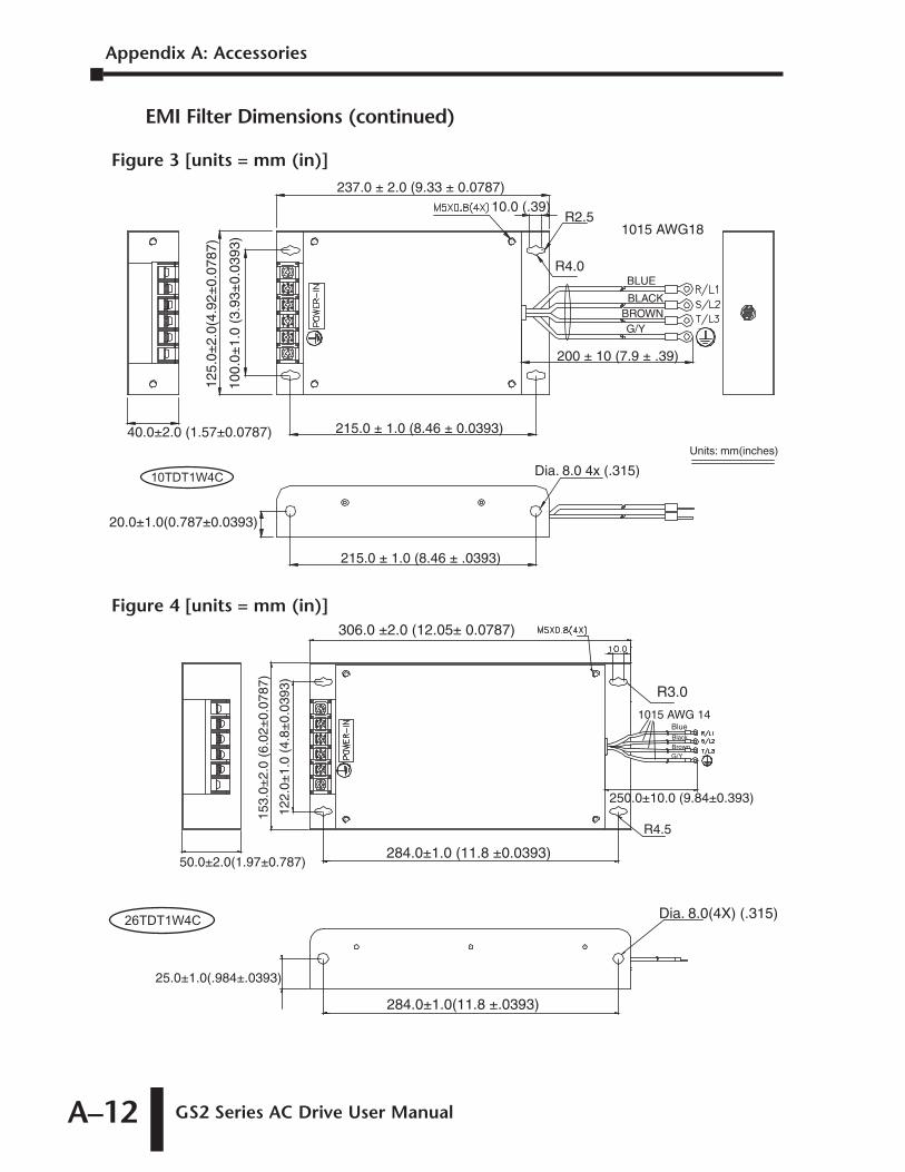
Appendix A: Accessories
GS2 Series AC Drive User ManualA–12
EMI Filter Dimensions (continued)
Figure 4 [units = mm (in)]306.0 ±2.0 (12.05± 0.0787)
R3.0
284.0±1.0 (11.8 ±0.0393)
284.0±1.0(11.8 ±.0393)
Dia. 8.0(4X) (.315)
25.0±1.0(.984±.0393)
50.0±2.0(1.97±0.787)
153.
0±2.
0 (6
.02±
0.07
87)
122.
0±1.
0 (4
.8±
0.03
93)
250.0±10.0 (9.84±0.393)
R4.5
1015 AWG 14BlueBlackBrownG/Y
26TDT1W4C
237.0 ± 2.0 (9.33 ± 0.0787)10.0 (.39)
R2.5
R4.0
200 ± 10 (7.9 ± .39)
1015 AWG18
BLUE
BLACKBROWNG/Y
215.0 ± 1.0 (8.46 ± 0.0393)40.0±2.0 (1.57±0.0787)
125.
0±2.
0(4.
92±
0.07
87)
100.
0±1.
0 (3
.93±
0.03
93)
215.0 ± 1.0 (8.46 ± .0393)
20.0±1.0(0.787±0.0393)
Units: mm(inches)
Dia. 8.0 4x (.315)10TDT1W4C
Figure 3 [units = mm (in)]
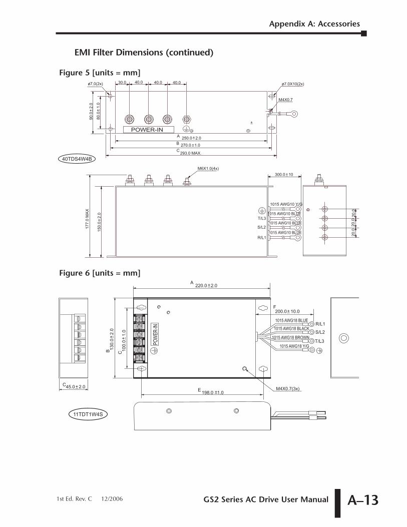
GS2 Series AC Drive User Manual A–13
EMI Filter Dimensions (continued)
POW
ER-IN
C45.0 2.0+_
C 100.
0 1
.0+_
B 130.
0 2
.0+_
M4X0.7(3x)
200.0 10.0+_
1015 AWG18 BLUE
1015 AWG18 BLACK
1015 AWG18 BROWN
1015 AWG18 Y/G
R/L1
S/L2
T/L3
E 198.0 1.0+_
A220.0 2.0+_
F
11TDT1W4S
Figure 6 [units = mm]
30.0 40.0 40.0 40.0
A
B
C293.0 MAX.
250.0 2.0+_
270.0 1.0+_
1015 AWG10 Y/G
1015 AWG10 BLUE
1015 AWG10 BLUE
1015 AWG10 BLUE
80.0
1.
0+_
o7,0(2x) o7.0X10(2x)
M4X0.7
+_300.0 10
+_
T/L3
S/L2
R/L1
20.0
20.0
20.0
150.
0 2
.0+_
177.
0 M
AX
90.0
2.
0+_
M6X1.0(4x)
POWER-IN
40TDS4W4B
Figure 5 [units = mm]
Appendix A: Accessories
1st Ed. Rev. C 12/2006
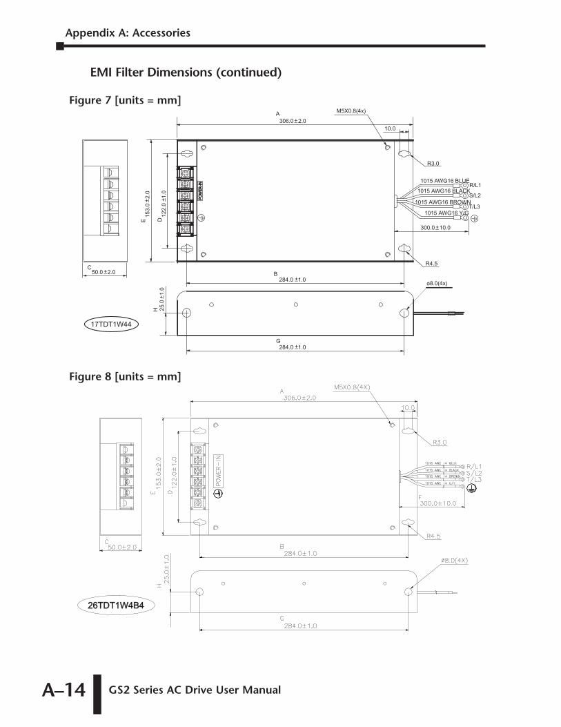
Appendix A: Accessories
GS2 Series AC Drive User ManualA–14
EMI Filter Dimensions (continued)
26TDT1W4B426TDT1W4B4
Figure 8 [units = mm]
POW
ER-IN
POW
ER-IN
C50.0 2.0+_
E D
B
G
A
H
300.0 10.0+_
25.0
1.
0+_
306.0 2.0+_
122.
0 1
.0+_
153.
0 2
.0+_
284.0 1.0+_
o8.0(4x)284.0 1.0+_
R4.5
M5X0.8(4x)
10.0
R3.0
1015 AWG16 BLUE
1015 AWG16 BLACK
1015 AWG16 BROWN
1015 AWG16 Y/G
R/L1
S/L2
T/L3
17TDT1W44
Figure 7 [units = mm]
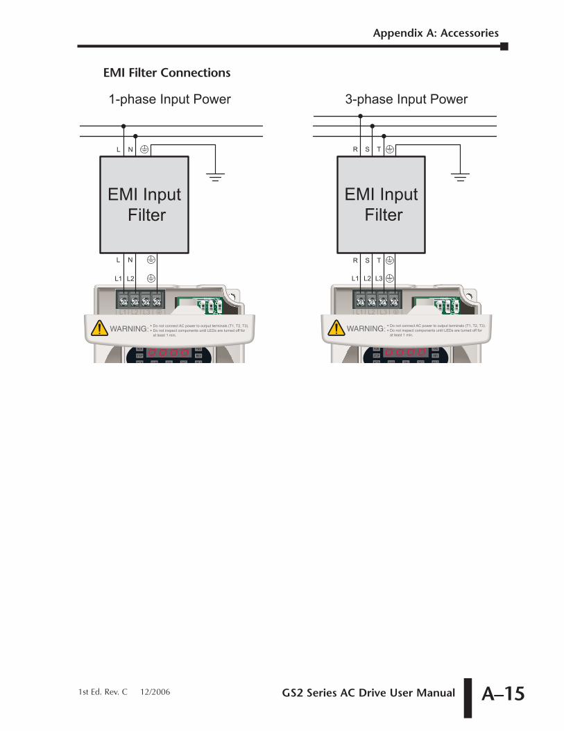
GS2 Series AC Drive User Manual A–15
EMI Filter Connections
L1 L2
EMI Input
Filter
L N
L1 L2
R S
L3
EMI Input
Filter
T
1-phase Input Power 3-phase Input Power
L N R S T
Appendix A: Accessories
1st Ed. Rev. C 12/2006
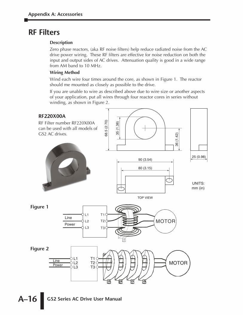
Appendix A: Accessories
GS2 Series AC Drive User ManualA–16
RF FiltersDescription
Zero phase reactors, (aka RF noise filters) help reduce radiated noise from the ACdrive power wiring. These RF filters are effective for noise reduction on both theinput and output sides of AC drives. Attenuation quality is good in a wide rangefrom AM band to 10 MHz.
Wiring Method
Wind each wire four times around the core, as shown in Figure 1. The reactorshould me mounted as closely as possible to the drive.
If you are unable to wire as described above due to wire size or another aspectsof your application, put all wires through four reactor cores in series withoutwinding, as shown in Figure 2.
L1L2L3
T1T2T3
MOTORLinePower
Figure 2
MOTORT3
L1
L2
L3
T1
T2Line
Power
Figure 1
80 (3.15)
90 (3.54)25 (0.98)
68.5
(2.
70)
35 (
1.38
)
36 (
1.42
)
TOP VIEW
UNITS:mm (in)
RF220X00ARF Filter number RF220X00Acan be used with all models ofGS2 AC drives.
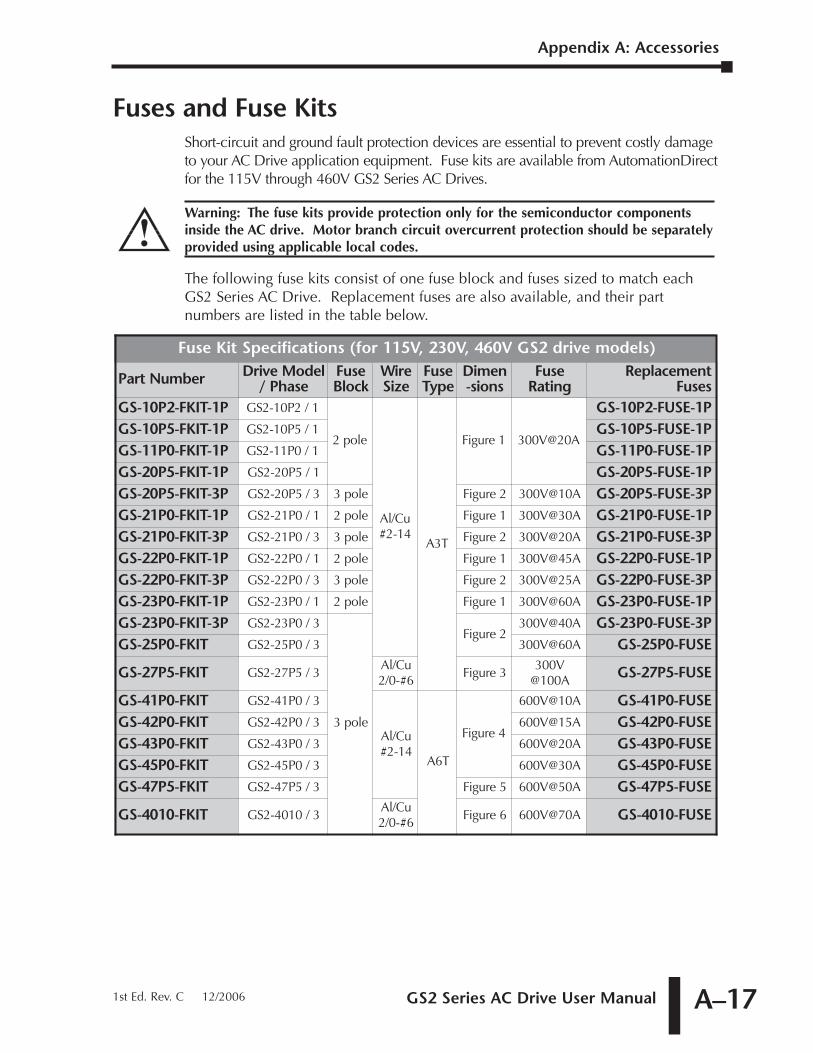
GS2 Series AC Drive User Manual A–17
Fuses and Fuse KitsShort-circuit and ground fault protection devices are essential to prevent costly damageto your AC Drive application equipment. Fuse kits are available from AutomationDirectfor the 115V through 460V GS2 Series AC Drives.
The following fuse kits consist of one fuse block and fuses sized to match eachGS2 Series AC Drive. Replacement fuses are also available, and their partnumbers are listed in the table below.
Fuse Kit Specifications (for 115V, 230V, 460V GS2 drive models)
Part Number Drive Model/ Phase
FuseBlock
WireSize
FuseType
Dimen-sions
FuseRating
ReplacementFuses
GS-10P2-FKIT-1P GS2-10P2 / 1
2 pole
Al/Cu#2-14
A3T
Figure 1 300V@20A
GS-10P2-FUSE-1PGS-10P5-FKIT-1P GS2-10P5 / 1 GS-10P5-FUSE-1PGS-11P0-FKIT-1P GS2-11P0 / 1 GS-11P0-FUSE-1PGS-20P5-FKIT-1P GS2-20P5 / 1 GS-20P5-FUSE-1PGS-20P5-FKIT-3P GS2-20P5 / 3 3 pole Figure 2 300V@10A GS-20P5-FUSE-3PGS-21P0-FKIT-1P GS2-21P0 / 1 2 pole Figure 1 300V@30A GS-21P0-FUSE-1PGS-21P0-FKIT-3P GS2-21P0 / 3 3 pole Figure 2 300V@20A GS-21P0-FUSE-3PGS-22P0-FKIT-1P GS2-22P0 / 1 2 pole Figure 1 300V@45A GS-22P0-FUSE-1PGS-22P0-FKIT-3P GS2-22P0 / 3 3 pole Figure 2 300V@25A GS-22P0-FUSE-3PGS-23P0-FKIT-1P GS2-23P0 / 1 2 pole Figure 1 300V@60A GS-23P0-FUSE-1PGS-23P0-FKIT-3P GS2-23P0 / 3
3 pole
Figure 2300V@40A GS-23P0-FUSE-3P
GS-25P0-FKIT GS2-25P0 / 3 300V@60A GS-25P0-FUSE
GS-27P5-FKIT GS2-27P5 / 3Al/Cu2/0-#6
Figure 3300V
@100A GS-27P5-FUSE
GS-41P0-FKIT GS2-41P0 / 3
Al/Cu#2-14
A6T
Figure 4
600V@10A GS-41P0-FUSEGS-42P0-FKIT GS2-42P0 / 3 600V@15A GS-42P0-FUSEGS-43P0-FKIT GS2-43P0 / 3 600V@20A GS-43P0-FUSEGS-45P0-FKIT GS2-45P0 / 3 600V@30A GS-45P0-FUSEGS-47P5-FKIT GS2-47P5 / 3 Figure 5 600V@50A GS-47P5-FUSE
GS-4010-FKIT GS2-4010 / 3Al/Cu2/0-#6
Figure 6 600V@70A GS-4010-FUSE
Warning: The fuse kits provide protection only for the semiconductor componentsinside the AC drive. Motor branch circuit overcurrent protection should be separatelyprovided using applicable local codes.
Appendix A: Accessories
1st Ed. Rev. C 12/2006
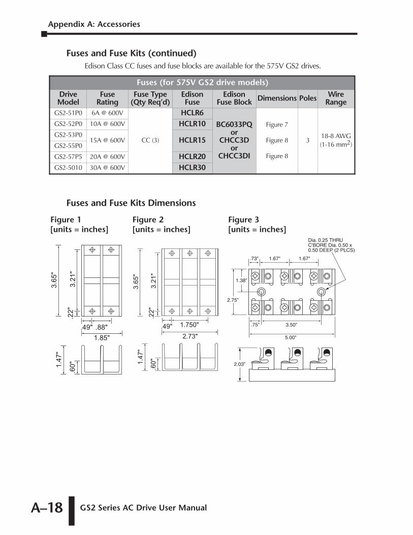
Appendix A: Accessories
GS2 Series AC Drive User ManualA–18
Fuses and Fuse Kits (continued)Edison Class CC fuses and fuse blocks are available for the 575V GS2 drives.
Fuses and Fuse Kits Dimensions
.88"
1.85"
.49"
3.6
5"
3.2
1"
.22
"
1.4
7"
.60
"
1.750"
2.73"
.49"
3.6
5"
3.2
1"
.22
"
1.4
7"
.60
"
3.50"
5.00"
1.67".73"
.75"
1.67"
1.38”
2.75”
2.03”
Dia. 0.25 THRUC'BORE Dia. 0.50 x0.50 DEEP (2 PLCS)
Figure 1 [units = inches]
Figure 2 [units = inches]
Figure 3 [units = inches]
Fuses (for 575V GS2 drive models)DriveModel
FuseRating
Fuse Type(Qty Req’d)
EdisonFuse
EdisonFuse Block Dimensions Poles Wire
RangeGS2-51P0 6A @ 600V
CC (3)
HCLR6
BC6033PQor
CHCC3Dor
CHCC3DI
Figure 7
Figure 8
Figure 8
318-8 AWG(1-16 mm2)
GS2-52P0 10A @ 600V HCLR10GS2-53P0
15A @ 600V HCLR15GS2-55P0
GS2-57P5 20A @ 600V HCLR20GS2-5010 30A @ 600V HCLR30
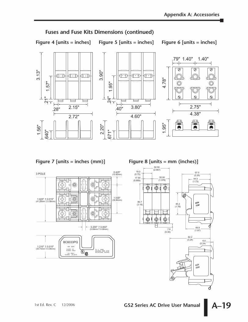
GS2 Series AC Drive User Manual A–19
Fuses and Fuse Kits Dimensions (continued)
1.625" + 0.015"(41.28mm + 0.38mm)
R
BUSSMANNCOOPER INDUSTRIESST. LOUIS, MO 63178MADE IN U.S.A.
75 C WIRE200,000A RMS SYMWITHSTAND RATING
Buss ®BC6033PQ30A 600V
CLASS CCFUSES ONLY
CU ONLY10 AWG 20 LB·IN
0.200" + 0.003"(5.08mm + 0.08mm)
0.425"(10.80mm)
1.530"(38.86mm)
3 POLE
1.210" + 0.015"(30.73mm + 0.38mm)
52.50(2.067)
19.0(0.75)17.50
(0.689)35.00
(1.378)
45.2(1.78)
80.7(3.18)
49.9(1.97)7.6
(0.30)
57.5(2.26)
44.0(1.73)
82.2(3.24) 6.0
(0.24)
Figure 7 [units = inches (mm)] Figure 8 [units = mm (inches)]
2.15"
2.72"
.28"
3.1
3"
1.5
7"
.21"
1.5
6"
.64
0"
3.80"
4.60"
.40"
3.9
0"
1.9
5"
.24
"
2.2
0"
.67
1"2.75"
4.38"
1.40".79" 1.40"
4.7
8"
1.9
5"
Figure 4 [units = inches] Figure 5 [units = inches] Figure 6 [units = inches]
Appendix A: Accessories
1st Ed. Rev. C 12/2006
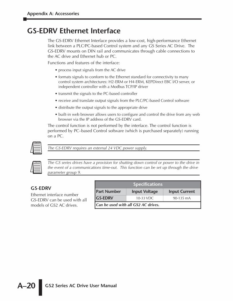
Appendix A: Accessories
GS2 Series AC Drive User ManualA–20
GS-EDRV Ethernet InterfaceThe GS-EDRV Ethernet Interface provides a low-cost, high-performance Ethernetlink between a PLC/PC-based Control system and any GS Series AC Drive. TheGS-EDRV mounts on DIN rail and communicates through cable connections tothe AC drive and Ethernet hub or PC.
Functions and features of the interface:
• process input signals from the AC drive
• formats signals to conform to the Ethernet standard for connectivity to manycontrol system architectures: H2-ERM or H4-ERM, KEPDirect EBC I/O server, orindependent controller with a Modbus TCP/IP driver
• transmit the signals to the PC-based controller
• receive and translate output signals from the PLC/PC-based Control software
• distribute the output signals to the appropriate drive
• built-in web browser allows users to configure and control the drive from any webbrowser via the IP address of the GS-EDRV card.
The control function is not performed by the interface. The control function isperformed by PC–based Control software (which is purchased separately) runningon a PC.
Specifications
Part Number Input Voltage Input Current
GS-EDRV 10-33 VDC 90-135 mA
Can be used with all GS2 AC drives.
GS-EDRVEthernet interface number GS-EDRV can be used with allmodels of GS2 AC drives.
The GS series drives have a provision for shutting down control or power to the drive inthe event of a communications time-out. This function can be set up through the driveparameter group 9.
The GS-EDRV requires an external 24 VDC power supply.
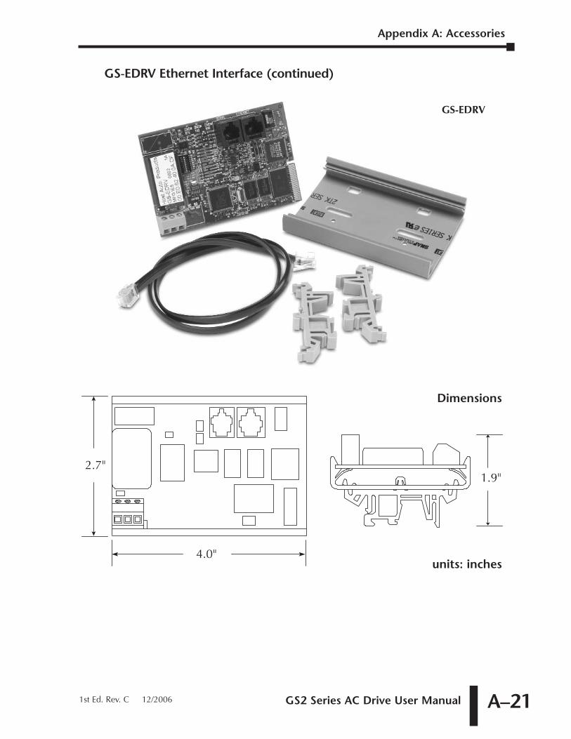
GS2 Series AC Drive User Manual A–21
GS-EDRV Ethernet Interface (continued)
4.0"
2.7"1.9"
Dimensions
units: inches
GS-EDRV
Appendix A: Accessories
1st Ed. Rev. C 12/2006
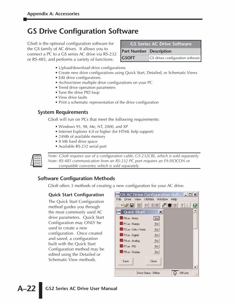
Appendix A: Accessories
GS2 Series AC Drive User ManualA–22
GS Drive Configuration Software
• Upload/download drive configurations • Create new drive configurations using Quick Start, Detailed, or Schematic Views• Edit drive configurations• Archive/store multiple drive configurations on your PC• Trend drive operation parameters• Tune the drive PID loop• View drive faults• Print a schematic representation of the drive configuration
System RequirementsGSoft will run on PCs that meet the following requirements:
• Windows 95, 98, Me, NT, 2000, and XP• Internet Explorer 4.0 or higher (for HTML help support)• 24Mb of available memory• 8 Mb hard drive space• Available RS-232 serial port
Software Configuration MethodsGSoft offers 3 methods of creating a new configuration for your AC drive.
Quick Start ConfigurationThe Quick Start Configurationmethod guides you throughthe most commonly used ACdrive parameters. Quick StartConfiguration may ONLY beused to create a newconfiguration. Once createdand saved, a configurationbuilt with the Quick StartConfiguration method may beedited using the Detailed orSchematic View methods.
Note: GSoft requires use of a configuration cable, GS-232CBL, which is sold separately.Note: RS-485 communication from an RS-232 PC port requires an FA-ISOCON or
compatible converter, which is sold separately.
GS Series AC Drive Software
Part Number Description
GSOFT GS drives configuration software
GSoft is the optional configuration software forthe GS family of AC drives. It allows you toconnect a PC to a GS series AC drive via RS-232or RS-485, and performs a variety of functions:
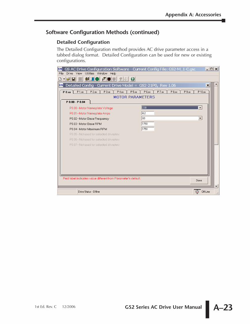
GS2 Series AC Drive User Manual A–23
Software Configuration Methods (continued)
Detailed ConfigurationThe Detailed Configuration method provides AC drive parameter access in atabbed dialog format. Detailed Configuration can be used for new or existingconfigurations.
Appendix A: Accessories
1st Ed. Rev. C 12/2006
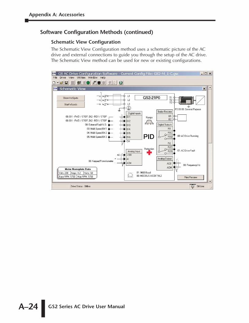
Appendix A: Accessories
GS2 Series AC Drive User ManualA–24
Software Configuration Methods (continued)
Schematic View ConfigurationThe Schematic View Configuration method uses a schematic picture of the ACdrive and external connections to guide you through the setup of the AC drive.The Schematic View method can be used for new or existing configurations.
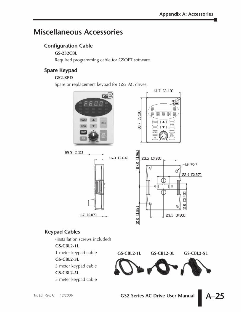
GS2 Series AC Drive User Manual A–25
Miscellaneous Accessories
Configuration CableGS-232CBL
Required programming cable for GSOFT software.
Spare KeypadGS2-KPD
Spare or replacement keypad for GS2 AC drives.
Keypad Cables(installation screws included)
GS-CBL2-1L
1 meter keypad cable
GS-CBL2-3L
3 meter keypad cable
GS-CBL2-5L
5 meter keypad cable
GS-CBL2-1L GS-CBL2-3L GS-CBL2-5L
M4*P0.7
0
STOP
PSET
MTR RAMP
PROT
RUN
100
REV
PID
V/Hz
DISP
DIGT
COMM
ANLG
FWD
Appendix A: Accessories
1st Ed. Rev. C 12/2006
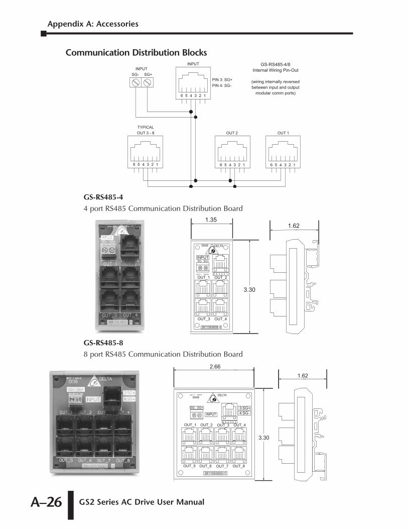
Appendix A: Accessories
GS2 Series AC Drive User ManualA–26
Communication Distribution Blocks
GS-RS485-4
4 port RS485 Communication Distribution Board
GS-RS485-8
8 port RS485 Communication Distribution Board
2.661.62
3.30
SG- SG+
OUT_1 OUT_2 OUT_3 OUT_4
DELTAECT 1 94V-D
0049
6 5 4 3 2 1
3:SG+4:SG-
3811093900 1
OUT_5 OUT_6 OUT_7 OUT_8
INPUT
INPUTSG- SG+
OUT_1 OUT_2
OUT_3 OUT_4
DELTA
ECT 1 94V-D
0049
6 5 4 3 2 1
3811093800 1
1.351.62
3.30
5 24 36 1
OUT 1OUT 2OUT 3 - 8
INPUTINPUT
SG- SG+PIN 3: SG+PIN 4: SG-
TYPICAL
5 24 36 1
5 24 36 1
5 24 36 1
GS-RS485-4/8Internal Wiring Pin-Out
(wiring internally reversedbetween input and output
modular comm ports)
USING GS2 AC DRIVES WITH
DIRECTLOGIC PLCS BAPPENDIXAPPENDIX
BBAPPENDIX
In This Appendix
Compatible DirectLOGIC PLCs and Modules . . . . .B–2
Typical Connections to the GS2 Series AC Drive . .B–7DC Output Modules . . . . . . . . . . . . . . . . . . . . . . . . . . . . . . . . . .B–7
Isolated Analog Output Modules . . . . . . . . . . . . . . . . . . . . . . . . .B–8
Non-Isolated Voltage or Sourcing Current Analog Output Modules . . . . . . . . . . . . . . . . . . . . . . . . . . . . . . . . . . . . . . . . . . . . . . . . . . .B–9
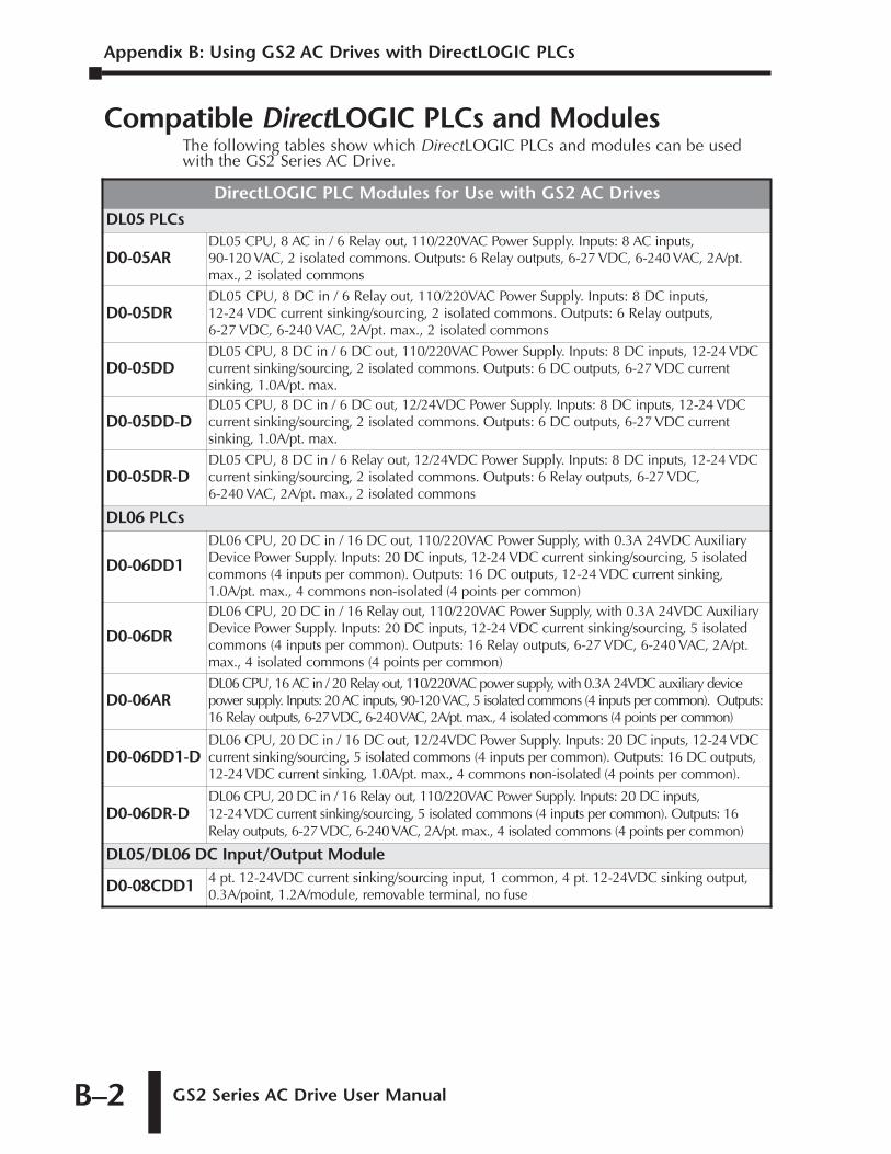
Appendix B: Using GS2 AC Drives with DirectLOGIC PLCs
GS2 Series AC Drive User ManualB–2
Compatible DirectLOGIC PLCs and ModulesThe following tables show which DirectLOGIC PLCs and modules can be usedwith the GS2 Series AC Drive.
DirectLOGIC PLC Modules for Use with GS2 AC DrivesDL05 PLCs
D0-05ARDL05 CPU, 8 AC in / 6 Relay out, 110/220VAC Power Supply. Inputs: 8 AC inputs,90-120 VAC, 2 isolated commons. Outputs: 6 Relay outputs, 6-27 VDC, 6-240 VAC, 2A/pt.max., 2 isolated commons
D0-05DRDL05 CPU, 8 DC in / 6 Relay out, 110/220VAC Power Supply. Inputs: 8 DC inputs,12-24 VDC current sinking/sourcing, 2 isolated commons. Outputs: 6 Relay outputs,6-27 VDC, 6-240 VAC, 2A/pt. max., 2 isolated commons
D0-05DDDL05 CPU, 8 DC in / 6 DC out, 110/220VAC Power Supply. Inputs: 8 DC inputs, 12-24 VDCcurrent sinking/sourcing, 2 isolated commons. Outputs: 6 DC outputs, 6-27 VDC currentsinking, 1.0A/pt. max.
D0-05DD-DDL05 CPU, 8 DC in / 6 DC out, 12/24VDC Power Supply. Inputs: 8 DC inputs, 12-24 VDCcurrent sinking/sourcing, 2 isolated commons. Outputs: 6 DC outputs, 6-27 VDC currentsinking, 1.0A/pt. max.
D0-05DR-DDL05 CPU, 8 DC in / 6 Relay out, 12/24VDC Power Supply. Inputs: 8 DC inputs, 12-24 VDCcurrent sinking/sourcing, 2 isolated commons. Outputs: 6 Relay outputs, 6-27 VDC,6-240 VAC, 2A/pt. max., 2 isolated commons
DL06 PLCs
D0-06DD1
DL06 CPU, 20 DC in / 16 DC out, 110/220VAC Power Supply, with 0.3A 24VDC AuxiliaryDevice Power Supply. Inputs: 20 DC inputs, 12-24 VDC current sinking/sourcing, 5 isolatedcommons (4 inputs per common). Outputs: 16 DC outputs, 12-24 VDC current sinking,1.0A/pt. max., 4 commons non-isolated (4 points per common)
D0-06DR
DL06 CPU, 20 DC in / 16 Relay out, 110/220VAC Power Supply, with 0.3A 24VDC AuxiliaryDevice Power Supply. Inputs: 20 DC inputs, 12-24 VDC current sinking/sourcing, 5 isolatedcommons (4 inputs per common). Outputs: 16 Relay outputs, 6-27 VDC, 6-240 VAC, 2A/pt.max., 4 isolated commons (4 points per common)
D0-06ARDL06 CPU, 16 AC in / 20 Relay out, 110/220VAC power supply, with 0.3A 24VDC auxiliary devicepower supply. Inputs: 20 AC inputs, 90-120 VAC, 5 isolated commons (4 inputs per common). Outputs:16 Relay outputs, 6-27 VDC, 6-240 VAC, 2A/pt. max., 4 isolated commons (4 points per common)
D0-06DD1-DDL06 CPU, 20 DC in / 16 DC out, 12/24VDC Power Supply. Inputs: 20 DC inputs, 12-24 VDCcurrent sinking/sourcing, 5 isolated commons (4 inputs per common). Outputs: 16 DC outputs,12-24 VDC current sinking, 1.0A/pt. max., 4 commons non-isolated (4 points per common).
D0-06DR-DDL06 CPU, 20 DC in / 16 Relay out, 110/220VAC Power Supply. Inputs: 20 DC inputs,12-24VDC current sinking/sourcing, 5 isolated commons (4 inputs per common). Outputs: 16Relay outputs, 6-27 VDC, 6-240 VAC, 2A/pt. max., 4 isolated commons (4 points per common)
DL05/DL06 DC Input/Output Module
D0-08CDD1 4 pt. 12-24VDC current sinking/sourcing input, 1 common, 4 pt. 12-24VDC sinking output,0.3A/point, 1.2A/module, removable terminal, no fuse
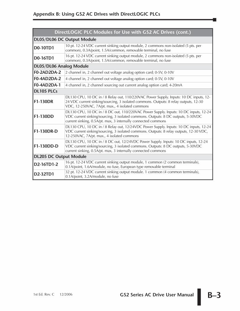
GS2 Series AC Drive User Manual B–3
Appendix B: Using GS2 AC Drives with DirectLOGIC PLCs
1st Ed. Rev. C 12/2006
DirectLOGIC PLC Modules for Use with GS2 AC Drives (cont.)
DL05/DL06 DC Output Module
D0-10TD1 10 pt. 12-24 VDC current sinking output module, 2 commons non-isolated (5 pts. percommon), 0.3A/point, 1.5A/common, removable terminal, no fuse
D0-16TD1 16 pt. 12-24 VDC current sinking output module, 2 commons non-isolated (5 pts. percommon), 0.3A/point, 1.5A/common, removable terminal, no fuse
DL05/DL06 Analog ModuleF0-2AD2DA-2 2 channel in, 2 channel out voltage analog option card; 0-5V, 0-10V
F0-4AD2DA-2 4 channel in, 2 channel out voltage analog option card; 0-5V, 0-10V
F0-4AD2DA-1 4 channel in, 2 channel sourcing out current analog option card; 4-20mA
DL105 PLCs
F1-130DRDL130 CPU, 10 DC in / 8 Relay out, 110/220VAC Power Supply. Inputs: 10 DC inputs, 12-24 VDC current sinking/sourcing, 3 isolated commons. Outputs: 8 relay outputs, 12-30VDC, 12-250VAC, 7A/pt. max., 4 isolated commons
F1-130DDDL130 CPU, 10 DC in / 8 DC out, 110/220VAC Power Supply. Inputs: 10 DC inputs, 12-24VDC current sinking/sourcing, 3 isolated commons. Outputs: 8 DC outputs, 5-30VDCcurrent sinking, 0.5A/pt. max, 3 internally connected commons
F1-130DR-DDL130 CPU, 10 DC in / 8 Relay out, 12/24VDC Power Supply. Inputs: 10 DC inputs, 12-24VDC current sinking/sourcing, 3 isolated commons. Outputs: 8 relay outputs, 12-30 VDC,12-250VAC, 7A/pt. max., 4 isolated commons
F1-130DD-DDL130 CPU, 10 DC in / 8 DC out, 12/24VDC Power Supply. Inputs: 10 DC inputs, 12-24VDC current sinking/sourcing, 3 isolated commons. Outputs: 8 DC outputs, 5-30VDCcurrent sinking, 0.5A/pt. max, 3 internally connected commons
DL205 DC Output Module
D2-16TD1-2 16 pt. 12-24 VDC current sinking output module, 1 common (2 common terminals),0.1A/point, 1.6A/module, no fuse, European type removable terminal
D2-32TD1 32 pt. 12-24 VDC current sinking output module. 1 common (4 common terminals),0.1A/point, 3.2A/module, no fuse
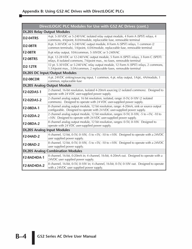
Appendix B: Using GS2 AC Drives with DirectLOGIC PLCs
GS2 Series AC Drive User ManualB–4
DirectLOGIC PLC Modules for Use with GS2 AC Drives (cont.)DL205 Relay Output Modules
D2-04TRS 4-pt. 5-30 VDC or 5-240 VAC isolated relay output module, 4 Form A (SPST) relays, 4commons, 4A/point, 8.0A/module, replaceable fuse, removable terminal
D2-08TR 8-pt. 5-30 VDC or 5-240 VAC output module, 8 Form A (SPST) relays, 1 common (2common terminals), 1A/point, 4.0A/module, replaceable fuse, removable terminal
F2-08TR 8-pt relay output, 10A/common, 5-30VDC or 5-240VAC
F2-08TRS 8-pt. 12-28 VDC or 12-240 VAC output module, 5 Form A (SPST) relays, 3 Form C (SPDT)relays, 8 isolated commons, 7A/point max., no fuses, removable terminal
D2-12TR 12 pt. 5-30 VDC or 5-240 VAC relay output module, 12 Form A (SPST) relays, 2 commons,1.5A/point max., 3.0A/common, 2 replaceable fuses, removable terminal
DL205 DC Input/Output Modules
D2-08CDR 4 pt. 24VDC sinking/sourcing input, 1 common, 4 pt. relay output, 1A/pt., 4A/module, 1common, replaceable fuse
DL205 Analog Output Module
F2-02DAS-1 2 channel, 16-bit resolution, Isolated 4-20mA sourcing (2 isolated commons). Designed tooperate with 24 VDC user-supplied power supply.
F2-02DAS-2 2 channel analog output, 16 bit resolution, isolated, range: 0-5V, 0-10V (2 isolatedcommons). Designed to operate with 24 VDC user-supplied power supply.
F2-08DA-1 8 channel analog output module, 12 bit resolution, range: 4-20mA, sink or source outputconfigurable. Designed to operate with 24 VDC user-supplied power supply.
F2-02DA-2 2 channel analog output module, 12 bit resolution, ranges: 0-5V, 0-10V, -5 to +5V, -10 to+10V. Designed to operate with 24 VDC user-supplied power supply.
F2-08DA-2 8 channel analog output module, 12 bit resolution, ranges: 0-5V, 0-10V. Designed tooperate with 24 VDC user-supplied power supply.
DL205 Analog Input Modules
F2-04AD-2 4 channel, 12-bit, 0-5V, 0-10V, -5 to +5V, -10 to +10V. Designed to operate with a 24VDCuser supplied power supply.
F2-08AD-2 8 channel, 12-bit, 0-5V, 0-10V, -5 to +5V, -10 to +10V. Designed to operate with a 24VDCuser supplied power supply.
DL205 Analog Combination Modules
F2-8AD4DA-1 8 channel, 16-bit, 0-20mA in; 4 channel, 16-bit, 4-20mA out. Designed to operate with a24VDC user supplied power supply.
F2-8AD4DA-2 8 channel, 16-bit, 0-5V, 0-10V in; 4 channel, 16-bit, 0-5V, 0-10V out. Designed to operatewith a 24VDC user supplied power supply.
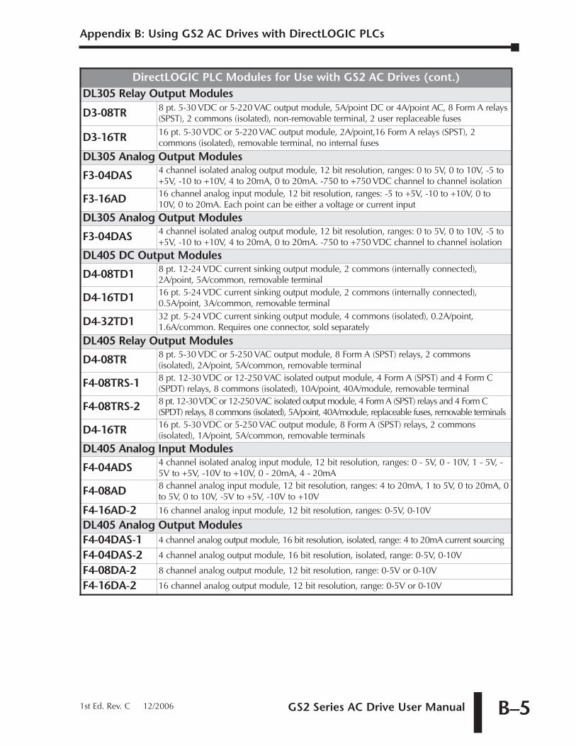
GS2 Series AC Drive User Manual B–5
Appendix B: Using GS2 AC Drives with DirectLOGIC PLCs
1st Ed. Rev. C 12/2006
DirectLOGIC PLC Modules for Use with GS2 AC Drives (cont.)DL305 Relay Output Modules
D3-08TR 8 pt. 5-30 VDC or 5-220 VAC output module, 5A/point DC or 4A/point AC, 8 Form A relays(SPST), 2 commons (isolated), non-removable terminal, 2 user replaceable fuses
D3-16TR 16 pt. 5-30 VDC or 5-220 VAC output module, 2A/point,16 Form A relays (SPST), 2commons (isolated), removable terminal, no internal fuses
DL305 Analog Output Modules
F3-04DAS 4 channel isolated analog output module, 12 bit resolution, ranges: 0 to 5V, 0 to 10V, -5 to+5V, -10 to +10V, 4 to 20mA, 0 to 20mA. -750 to +750 VDC channel to channel isolation
F3-16AD 16 channel analog input module, 12 bit resolution, ranges: -5 to +5V, -10 to +10V, 0 to10V, 0 to 20mA. Each point can be either a voltage or current input
DL305 Analog Output Modules
F3-04DAS 4 channel isolated analog output module, 12 bit resolution, ranges: 0 to 5V, 0 to 10V, -5 to+5V, -10 to +10V, 4 to 20mA, 0 to 20mA. -750 to +750 VDC channel to channel isolation
DL405 DC Output Modules
D4-08TD1 8 pt. 12-24 VDC current sinking output module, 2 commons (internally connected),2A/point, 5A/common, removable terminal
D4-16TD1 16 pt. 5-24 VDC current sinking output module, 2 commons (internally connected),0.5A/point, 3A/common, removable terminal
D4-32TD1 32 pt. 5-24 VDC current sinking output module, 4 commons (isolated), 0.2A/point,1.6A/common. Requires one connector, sold separately
DL405 Relay Output Modules
D4-08TR 8 pt. 5-30 VDC or 5-250 VAC output module, 8 Form A (SPST) relays, 2 commons(isolated), 2A/point, 5A/common, removable terminal
F4-08TRS-1 8 pt. 12-30 VDC or 12-250 VAC isolated output module, 4 Form A (SPST) and 4 Form C(SPDT) relays, 8 commons (isolated), 10A/point, 40A/module, removable terminal
F4-08TRS-2 8 pt. 12-30 VDC or 12-250 VAC isolated output module, 4 Form A (SPST) relays and 4 Form C(SPDT) relays, 8 commons (isolated), 5A/point, 40A/module, replaceable fuses, removable terminals
D4-16TR 16 pt. 5-30 VDC or 5-250 VAC output module, 8 Form A (SPST) relays, 2 commons(isolated), 1A/point, 5A/common, removable terminals
DL405 Analog Input Modules
F4-04ADS 4 channel isolated analog input module, 12 bit resolution, ranges: 0 - 5V, 0 - 10V, 1 - 5V, -5V to +5V, -10V to +10V, 0 - 20mA, 4 - 20mA
F4-08AD 8 channel analog input module, 12 bit resolution, ranges: 4 to 20mA, 1 to 5V, 0 to 20mA, 0to 5V, 0 to 10V, -5V to +5V, -10V to +10V
F4-16AD-2 16 channel analog input module, 12 bit resolution, ranges: 0-5V, 0-10V
DL405 Analog Output ModulesF4-04DAS-1 4 channel analog output module, 16 bit resolution, isolated, range: 4 to 20mA current sourcing
F4-04DAS-2 4 channel analog output module, 16 bit resolution, isolated, range: 0-5V, 0-10V
F4-08DA-2 8 channel analog output module, 12 bit resolution, range: 0-5V or 0-10V
F4-16DA-2 16 channel analog output module, 12 bit resolution, range: 0-5V or 0-10V
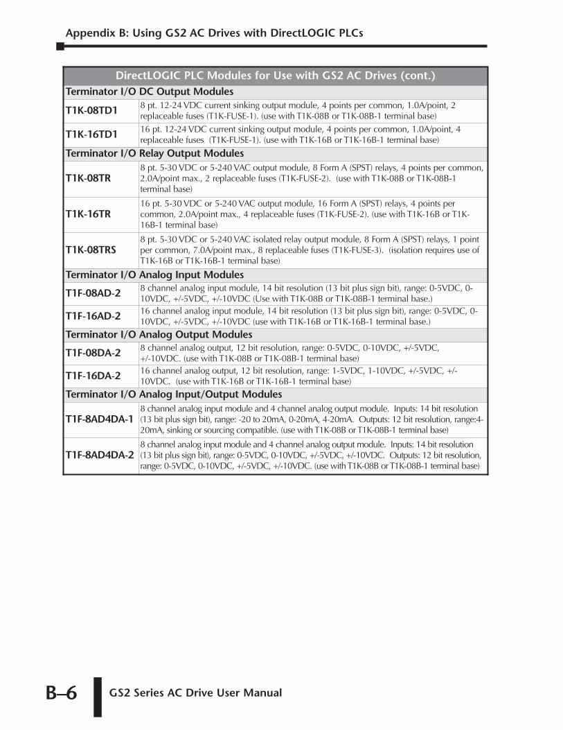
Appendix B: Using GS2 AC Drives with DirectLOGIC PLCs
GS2 Series AC Drive User ManualB–6
DirectLOGIC PLC Modules for Use with GS2 AC Drives (cont.)Terminator I/O DC Output Modules
T1K-08TD1 8 pt. 12-24 VDC current sinking output module, 4 points per common, 1.0A/point, 2replaceable fuses (T1K-FUSE-1). (use with T1K-08B or T1K-08B-1 terminal base)
T1K-16TD1 16 pt. 12-24 VDC current sinking output module, 4 points per common, 1.0A/point, 4replaceable fuses (T1K-FUSE-1). (use with T1K-16B or T1K-16B-1 terminal base)
Terminator I/O Relay Output Modules
T1K-08TR8 pt. 5-30 VDC or 5-240 VAC output module, 8 Form A (SPST) relays, 4 points per common,2.0A/point max., 2 replaceable fuses (T1K-FUSE-2). (use with T1K-08B or T1K-08B-1terminal base)
T1K-16TR16 pt. 5-30 VDC or 5-240 VAC output module, 16 Form A (SPST) relays, 4 points percommon, 2.0A/point max., 4 replaceable fuses (T1K-FUSE-2). (use with T1K-16B or T1K-16B-1 terminal base)
T1K-08TRS8 pt. 5-30 VDC or 5-240 VAC isolated relay output module, 8 Form A (SPST) relays, 1 pointper common, 7.0A/point max., 8 replaceable fuses (T1K-FUSE-3). (isolation requires use ofT1K-16B or T1K-16B-1 terminal base)
Terminator I/O Analog Input Modules
T1F-08AD-2 8 channel analog input module, 14 bit resolution (13 bit plus sign bit), range: 0-5VDC, 0-10VDC, +/-5VDC, +/-10VDC (Use with T1K-08B or T1K-08B-1 terminal base.)
T1F-16AD-2 16 channel analog input module, 14 bit resolution (13 bit plus sign bit), range: 0-5VDC, 0-10VDC, +/-5VDC, +/-10VDC (use with T1K-16B or T1K-16B-1 terminal base.)
Terminator I/O Analog Output Modules
T1F-08DA-2 8 channel analog output, 12 bit resolution, range: 0-5VDC, 0-10VDC, +/-5VDC, +/-10VDC. (use with T1K-08B or T1K-08B-1 terminal base)
T1F-16DA-2 16 channel analog output, 12 bit resolution, range: 1-5VDC, 1-10VDC, +/-5VDC, +/-10VDC. (use with T1K-16B or T1K-16B-1 terminal base)
Terminator I/O Analog Input/Output Modules
T1F-8AD4DA-18 channel analog input module and 4 channel analog output module. Inputs: 14 bit resolution(13 bit plus sign bit), range: -20 to 20mA, 0-20mA, 4-20mA. Outputs: 12 bit resolution, range:4-20mA, sinking or sourcing compatible. (use with T1K-08B or T1K-08B-1 terminal base)
T1F-8AD4DA-28 channel analog input module and 4 channel analog output module. Inputs: 14 bit resolution(13 bit plus sign bit), range: 0-5VDC, 0-10VDC, +/-5VDC, +/-10VDC. Outputs: 12 bit resolution,range: 0-5VDC, 0-10VDC, +/-5VDC, +/-10VDC. (use with T1K-08B or T1K-08B-1 terminal base)
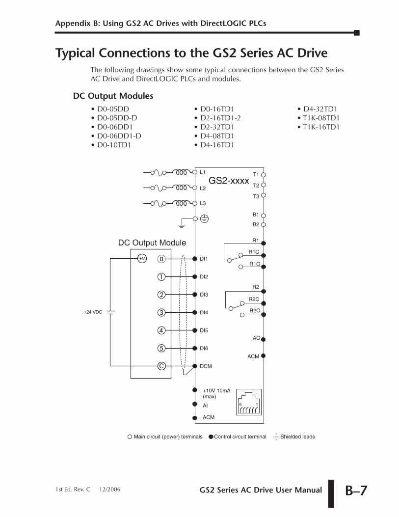
GS2 Series AC Drive User Manual B–7
Appendix B: Using GS2 AC Drives with DirectLOGIC PLCs
1st Ed. Rev. C 12/2006
Typical Connections to the GS2 Series AC DriveThe following drawings show some typical connections between the GS2 SeriesAC Drive and DirectLOGIC PLCs and modules.
DC Output Modules
Control circuit terminal Shielded leadsMain circuit (power) terminals
GS2-xxxx
B1
B2
T3
T1
T2
AO
ACM
DI1
DI2
DI3
DI4
DI5
DCM
DI6
+10V 10mA(max)
AI
ACM
R1C
R1
R1O
R2
R2C
R2O
L1
L3
L2
16
�
�
�
�
�
�
C
+V
+24 VDC
DC Output Module
• D0-05DD• D0-05DD-D• D0-06DD1• D0-06DD1-D• D0-10TD1
• D0-16TD1• D2-16TD1-2• D2-32TD1• D4-08TD1• D4-16TD1
• D4-32TD1• T1K-08TD1• T1K-16TD1
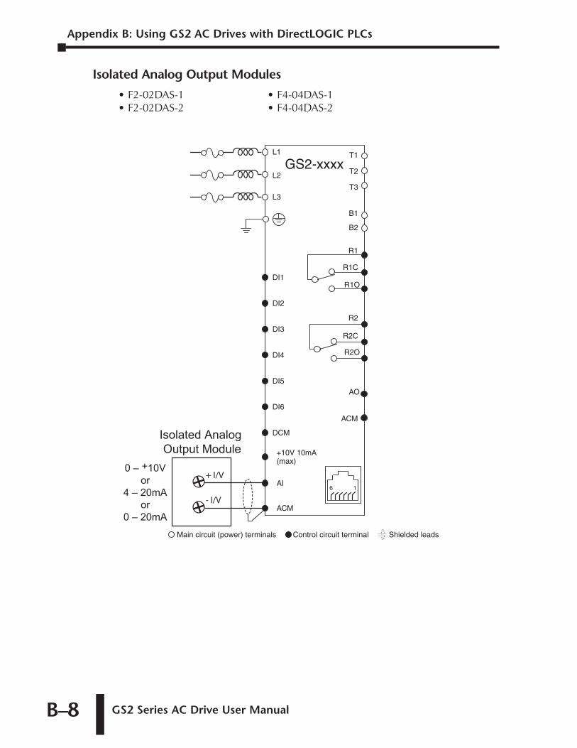
Appendix B: Using GS2 AC Drives with DirectLOGIC PLCs
GS2 Series AC Drive User ManualB–8
Isolated Analog Output Modules
Control circuit terminal Shielded leadsMain circuit (power) terminals
GS2-xxxx
B1
B2
T3
T1
T2
AO
ACM
DI1
DI2
DI3
DI4
DI5
DCM
DI6
+10V 10mA(max)
AI
ACM
R1C
R1
R1O
R2
R2C
R2O
L1
L3
L2
16
Isolated Analog Output Module
- I/V
+ I/V0 – +10V
or4 – 20mA
or0 – 20mA
• F2-02DAS-1• F2-02DAS-2
• F4-04DAS-1• F4-04DAS-2
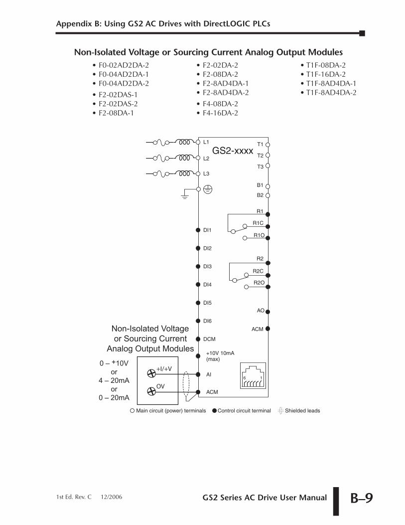
GS2 Series AC Drive User Manual B–9
Appendix B: Using GS2 AC Drives with DirectLOGIC PLCs
1st Ed. Rev. C 12/2006
Non-Isolated Voltage or Sourcing Current Analog Output Modules
Control circuit terminal Shielded leadsMain circuit (power) terminals
GS2-xxxx
B1
B2
T3
T1
T2
AO
ACM
DI1
DI2
DI3
DI4
DI5
DCM
DI6
+10V 10mA(max)
AI
ACM
R1C
R1
R1O
R2
R2C
R2O
L1
L3
L2
16
Non-Isolated Voltage or Sourcing Current
Analog Output Modules
OV
+I/+V0 – +10V
or4 – 20mA
or0 – 20mA
• F0-02AD2DA-2• F0-04AD2DA-1• F0-04AD2DA-2
• F2-02DAS-1• F2-02DAS-2• F2-08DA-1
• F2-02DA-2• F2-08DA-2• F2-8AD4DA-1• F2-8AD4DA-2
• F4-08DA-2• F4-16DA-2
• T1F-08DA-2• T1F-16DA-2• T1F-8AD4DA-1• T1F-8AD4DA-2

AAC Drives - Purpose; 1–3
Accel 1 to Accel 2 Frequency Transition; 4–16
Acceleration S-Curve; 4–14
Acceleration Time; 4–13
Accessories; 2–12, A–1
AFD - Adjustable Frequency Drive; 1–3
Agency Approvals; 1–8, 2–7
Air Flow; 2–3
Ambient Conditions; 1–8, 2–2
Amps/CurrentMotor Nameplate Amps; 4–11Over-Current Stall Prevention; 4–47Overload; 4–43
Analog InputExamples; 4–34Gain; 4–33Loss of ACI Signal; 4–40Offset; 4–33Offset Polarity; 4–32Reverse Motion Enable; 4–33
Analog Output; 4–40Gain; 4–40Signal; 4–40
Analog Parameters; 4–32
Applicable Codes; 2–7
Auto Adjustable Accel/Decel; 4–46
Auto Restart After Fault; 4–44
Auto Voltage Regulation; 4–45
Auto-torque Boost; 4–20
BBase-Block Time for Speed Search; 4–48
Block Transfer Parameters; 4–58, 5–29
Braking Resistors; 2–12, A–8
CCables
Configuration Cables; A–25Keypad Cables; A–25
CE; 1–8
CEC; 2–7
Circuit Connections Warnings & Notes; 2–6
Communicating with DirectLogic PLCs; 5–12
Communicating with Third-party Devices; 5–30
Communication Address; 4–56
Communication Connections to DL PLCs; 5–12
Communication Distribution Blocks; A–26
Communication Parameters; 4–56
Communication Protocol; 4–56
Communication Transmission Speed; 4–56
Compatibility, GS2 and Direct LOGIC PLCs; B–2
Configuration Cable; A–25
Configuration Software; A–22Configuration Cable; A–25
GS2 Series AC Drive User Manual I–11st Ed. Rev. C 12/2006
INDEX
Configuring/Programming the AC DriveKeypad Configuration; 3–5Software Configuration; A–22
Configuration Cable; A–25
Contactor; 2–6, 2–12
Contents of Drive Package; 1–3
Control Terminals & Wiring; 1–4, 2–10, 2–11
cUL; 1–8, 2–7
Current/AmpsMotor Nameplate Amps; 4–11Over-Current Stall Prevention; 4–47Overload; 4–43
DDC Injection
Current Level; 4–18during Start-up; 4–18during Stopping; 4–18Start-point; 4–18
Decel 1 to Decel 2 Frequency Transition; 4–16
Deceleration S-Curve; 4–15
Deceleration Time; 4–14
Default, Restore Parameters; 4–57
Desired Current; 4–31
Desired Frequency; 4–31
Dimensions; 2–4
Direction CommandDigital Input FWD/REV; 4–22Keypad FWD/REV; 3–3Serial Comm Direction Command; 4–59
DirectLOGIC Modbus PLC Programming; 5–16
DirectLOGIC PLCs; B–2
DirectLogic PLCs, Communicating with; 5–12
DisableDigital Input Disable; 4–23, 4–29Disable PID; 4–23
Disconnect switch; 2–6
Display; 3–2
Display Parameters; 4–55Display Frequency Scale Factor; 4–55
Display Function; 4–55
Distribution Blocks, Communication; A–26
EElectro-Magnetic Interference; 2–7
EMI; 2–7
EMI Filters; 2–12, A–10
Enclosure Rating; 1–8, 2–2
Environmental Conditions; 1–8, 2–2
Error Codes; 5–9, 6–3
Ethernet Interface; A–20
ExamplesAnalog Input Examples; 4–34DL PLC Program Example for Modbus; 5–16
External FaultExternal Fault, Digital Input; 4–23, 4–24External Fault, Serial Comm; 4–60
External Parts; 1–4Cover - lower terminals; 1–4Cover - upper terminals; 1–4DIP Switches; 1–4Keypad; 1–4Mounting Screw Holes; 1–4Nameplate Label; 1–4Terminals - control wiring; 1–4Terminals - power input wiring; 1–4Terminals - power output wiring; 1–4Ventilation Slots; 1–4
FFault Codes; 6–3
Fault Record; 4–50
Fault ResetExternal DI Fault Reset; 4–23, 4–24Keypad Fault Reset; 3–3Serial Comm Fault Reset; 4–60
Fault, External; 4–23, 4–24, 4–60
FiltersEMI Filters; 2–12, A–10RF Filters; A–16
Index
GS2 Series AC Drive User ManualI–2
FrequencyJog Frequency; 4–41Mid-point Frequency; 4–20Minimum Output Frequency; 4–21Motor Base Frequency; 4–12PID Output Frequency Limit; 4–54PWM Carrier Frequency; 4–21Source of Frequency Command; 4–32Volts/Hertz Parameters; 4–19
Frequency Command / Speed ReferenceSerial Comm Speed Reference; 4–59Source of Frequency Command; 4–32
Function Keys; 3–3
Fuses; 2–12, A–17
GGround Loops; 2–6
Grounding Resistance; 2–6
GS Series Number; 4–60
GS-EDRV Ethernet Interface; A–20
GSOFT Configuration Software; A–22Configuration Cable; A–25
IInspection; 6–2
Annual; 6–2Monthly; 6–2
Installation; 2–3Air Flow; 2–3Dimensions; 2–4Minimum Clearances; 2–3
Inverter; 1–3
JJog Command
Digital Input Jog Command; 4–23, 4–25Serial Comm Jog Command; 4–60
Jog Frequency; 4–41
K
Keypad; 3–2
Keypad Cables; A–25
Keypad, Spare; A–25
LLabel, Nameplate Information; 1–3
LED Display; 3–2
LED Indicators; 3–2
Lower Boundof Output Frequency; 4–49
MMaintenance; 6–2
Manufacturer Model Information; 4–61
Maximum Allowable Power Loss Time; 4–48
Maximum Speed Search Current Level; 4–48
Memory Addresses for Parameters; 5–4
Mid-point Frequency; 4–20
Mid-point Voltage; 4–20
Minimum Clearances; 2–3
Minimum Output Frequency; 4–21
Minimum Output Voltage; 4–21
Modbus ASCII; 5–30
Modbus Communication with Third-PartyDevices; 5–30
Modbus Communications; 5–1
Modbus Connections to DL PLCs; 5–12
Modbus Control, PLC Programming; 5–16
Modbus RTU; 5–30
Model Information; 4–61
Model Number Explanation; 1–3
Momentary Power Loss; 4–44
Motor Base Frequency; 4–12
Motor Base RPM; 4–12
Motor Maximum RPM; 4–12
Motor Nameplate Amps; 4–11
Motor Nameplate Voltage; 4–11
Motor Parameters; 4–11
Motors
GS2 Series AC Drive User Manual I–3
Index
1st Ed. Rev. C 12/2006
Single-Phase; 2–7Three-Phase; 1–3
Mounting Screw Holes; 1–4, 2–4
Multi-Function Input Disable; 4–29
Multi-function Input Terminals; 4–22
Multi-function Output Terminals; 4–30
Multi-SpeedAuto Voltage Regulation; 4–45Digital Input Multi-Speed Bits; 4–23, 4–25Multi-Speed Settings; 4–42
NNameplate Label Information; 1–3
NEC; 2–7
NEMA Publications; 1–2
OOperation Command; 4–22
Over-CurrentStall Prevention During Acceleration; 4–47Stall Prevention During Operation; 4–47
Overload; 4–43
Over-TorqueDetection Level; 4–46Detection Mode; 4–46Detection Time; 4–46
Over-VoltageStall Prevention; 4–45
PParameter Lock; 4–57
Parameter Memory Addresses; 5–4
Parameter Summary; 4–2
Parameters, Detailed Listings; 4–11Restore Parameters to Default Settings; 4–57
PIDPID Deviation Alarm; 4–30PID Deviation Level; 4–31PID Deviation Time; 4–31
PID DI Setpoint Bits; 4–23, 4–25
PID Deviation Alarm; 4–30
PID Parameters; 4–51Derivative Control; 4–53Derivative Filter Time Constant; 4–54Feedback Loss Operation; 4–54Feedback Signal Loss Detection Time; 4–54Input Terminal for PID Feedback; 4–51Integral Control; 4–53Keypad Setpoint; 4–52Multi-setpoints; 4–52Output Frequency Limit; 4–54Proportional Control; 4–53PV 100% Value; 4–52PV Setpoint Source; 4–52Upper Bound for Integral Control; 4–54
PID SP Digital Inputs; 4–23
PLC Module Typical Connections; B–7
PLC Modules; B–2
PLC Programming for Modbus Control; 5–16
PLCs, DirectLOGIC, Communicating with; 5–12
PotentiometerKeypad Potentiometer; 3–3Remote Potentiometer; 2–11
Power Terminals & Wiring; 1–4, 2–7, 2–8, 2–9,2–11
Present Fault Record; 4–50
Preset Parameters; 4–41
Programming/Configuring the AC DriveKeypad Configuration; 3–5Software Configuration; A–22
Configuration Cable; A–25
Protection Parameters; 4–43
Purpose of AC Drives; 1–3
PWM Carrier Frequency; 4–21
RRamp Parameters; 4–13
Reactors; 2–12, A–2
Reset, Fault
Index
GS2 Series AC Drive User ManualI–4
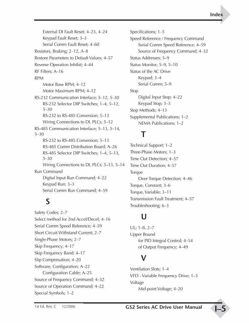
External DI Fault Reset; 4–23, 4–24Keypad Fault Reset; 3–3Serial Comm Fault Reset; 4–60
Resistors, Braking; 2–12, A–8
Restore Parameters to Default Values; 4–57
Reverse Operation Inhibit; 4–44
RF Filters; A–16
RPMMotor Base RPM; 4–12Motor Maximum RPM; 4–12
RS-232 Communication Interface; 5–12, 5–30RS-232 Selector DIP Switches; 1–4, 5–12,5–30RS-232 to RS-485 Conversion; 5–13Wiring Connections to DL PLCs; 5–12
RS-485 Communication Interface; 5–13, 5–14,5–30
RS-232 to RS-485 Conversion; 5–13RS-485 Comm Distribution Board; A–26RS-485 Selector DIP Switches; 1–4, 5–13,5–30Wiring Connections to DL PLCs; 5–13, 5–14
Run CommandDigital Input Run Command; 4–22Keypad Run; 3–3Serial Comm Run Command; 4–59
SSafety Codes; 2–7
Select method for 2nd Accel/Decel; 4–16
Serial Comm Speed Reference; 4–59
Short Circuit Withstand Current; 2–7
Single-Phase Motors; 2–7
Skip Frequency; 4–17
Skip Frequency Band; 4–17
Slip Compensation; 4–20
Software, Configuration; A–22Configuration Cable; A–25
Source of Frequency Command; 4–32
Source of Operation Command; 4–22
Special Symbols; 1–2
Specifications; 1–5
Speed Reference / Frequency CommandSerial Comm Speed Reference; 4–59Source of Frequency Command; 4–32
Status Addresses; 5–9
Status Monitor; 5–9, 5–10
Status of the AC DriveKeypad; 3–4Serial Comm; 5–9
StopDigital Input Stop; 4–22Keypad Stop; 3–3
Stop Methods; 4–13
Supplemental Publications; 1–2NEMA Publications; 1–2
TTechnical Support; 1–2
Three-Phase Motors; 1–3
Time Out Detection; 4–57
Time Out Duration; 4–57
TorqueOver-Torque Detection; 4–46
Torque, Constant; 3–6
Torque, Variable; 3–11
Transmission Fault Treatment; 4–57
Troubleshooting; 6–3
UUL; 1–8, 2–7
Upper Boundfor PID Integral Control; 4–54of Output Frequency; 4–49
VVentilation Slots; 1–4
VFD - Variable Frequency Drive; 1–3
VoltageMid-point Voltage; 4–20
GS2 Series AC Drive User Manual I–5
Index
1st Ed. Rev. C 12/2006
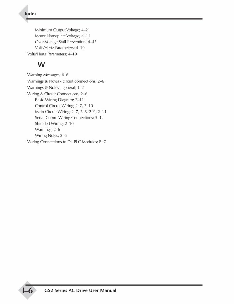
Minimum Output Voltage; 4–21Motor Nameplate Voltage; 4–11Over-Voltage Stall Prevention; 4–45Volts/Hertz Parameters; 4–19
Volts/Hertz Parameters; 4–19
WWarning Messages; 6–6
Warnings & Notes - circuit connections; 2–6
Warnings & Notes - general; 1–2
Wiring & Circuit Connections; 2–6Basic Wiring Diagram; 2–11Control Circuit Wiring; 2–7, 2–10Main Circuit Wiring; 2–7, 2–8, 2–9, 2–11Serial Comm Wiring Connections; 5–12Shielded Wiring; 2–10Warnings; 2–6Wiring Notes; 2–6
Wiring Connections to DL PLC Modules; B–7
Index
GS2 Series AC Drive User ManualI–6


![CCHAPTERHAPTER INSTALLATION WIRING · GS2-20P5, GS2-21P0, GS2-22P0, GS2-41P0, GS2-42P0, GS2-43P0, GS2-51P0, GS2-52P0, GS2-53P0 Units: mm [inches] GS2 Series AC Drive User Manual 2–5](https://img.pdfslide.net/doc/110x75/5e9f219cb4bfbb48920bd3b3/cchapterhapter-installation-wiring-gs2-20p5-gs2-21p0-gs2-22p0-gs2-41p0-gs2-42p0.jpg)