Embed Size (px)
Citation preview
1 | P a g e
Gammill, Inc. | 2017 CI-T-0005 – GS6 Hydraulic Lift Assembly Instructions – Rev 00
Tables & Accessories
GS6 Hydraulic Lift
Assembly Instructions
CI-T-0005 Rev 00
Materials Required: SEE PROVIDED PARTS INDEX 6.
STEP 1: Remove all 4 leveler feet from bottom of leg inserts by turning them counter-clockwise.
An adjustable wrench may be needed to loosen the jam nut on the leveler foot. Remove nut
from each leveler foot and set aside. They will be repurposed in an upcoming step.
STEP 2: Remove all
4 leg inserts from
both table legs by
loosening black
insert locking bolts
and removing
9/16” nuts,
washers, and
height adjustment
bolts using a 9/16”
socket wrench and
box wrench. For
new table
installations the
leg inserts should
be removed
before bolting legs
to table. Legs can either be carefully laid onto their side on a horizontal surface or rotated 90°
so that the back of the leg rests on the floor.
2 | P a g e
Gammill, Inc. | 2017 CI-T-0005 – GS6 Hydraulic Lift Assembly Instructions – Rev 00
Note: If installing hydraulics on a table that is already assembled, a small vehicle jack can be
used to lift one end of the table at a time so that the leg inserts can be removed from the
bottom of leg.
STEP 3: Install both legs onto table as you normally would.
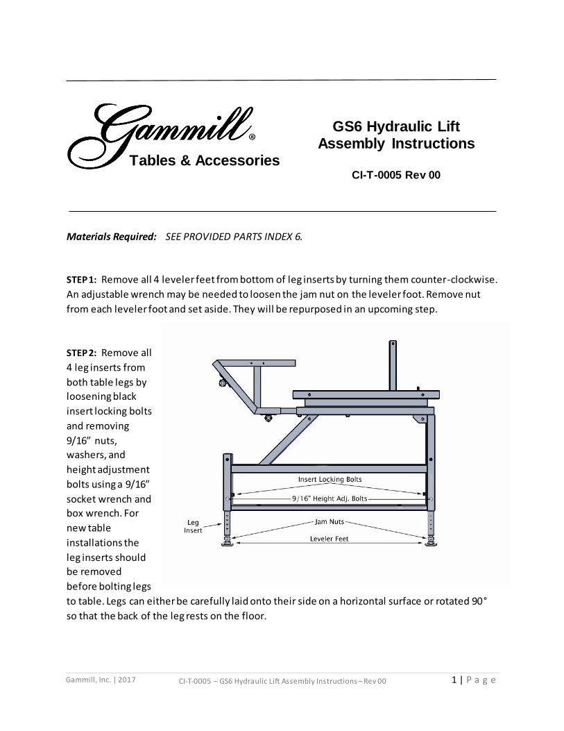
STEP 4: Install casters in the holes on the lower crosspiece using 5/8” flat washers, lock washers
and the 4 jam nuts which were removed from the leveler feet in STEP 1. Tighten jam nuts using
an adjustable wrench. Install locking casters on front side. (As shown.) Do this on both legs.
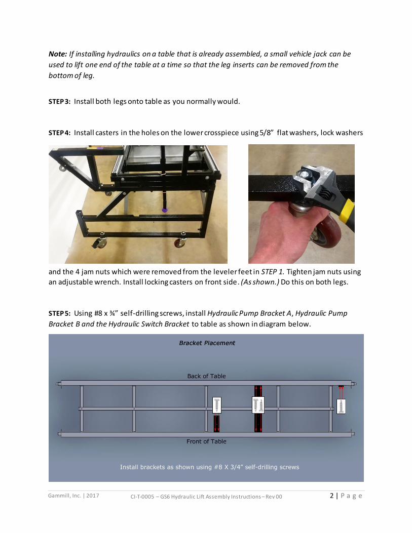
STEP 5: Using #8 x ¾” self-drilling screws, install Hydraulic Pump Bracket A, Hydraulic Pump
Bracket B and the Hydraulic Switch Bracket to table as shown in diagram below.

3 | P a g e
Gammill, Inc. | 2017 CI-T-0005 – GS6 Hydraulic Lift Assembly Instructions – Rev 00
STEP 6: Install Hydraulic Pump, Control Module and Switch onto mounting brackets and plug AC
power cord into module as shown in diagram below.
STEP 7: Remove ties from hydraulic hoses one at a time and carefully place one Hydraulic
Cylinder near each of the four corners of the table. (As shown.)
*IMPORTANT*
**DO NOT twist, bend,
pinch, kink, cut, or force
hydraulic hoses.**
Be extremely careful
when handling hydraulic
hoses. Damaging one
may cause the hydraulic
system to fail or function
improperly. Avoid
tangling hoses.
4 | P a g e
Gammill, Inc. | 2017 CI-T-0005 – GS6 Hydraulic Lift Assembly Instructions – Rev 00
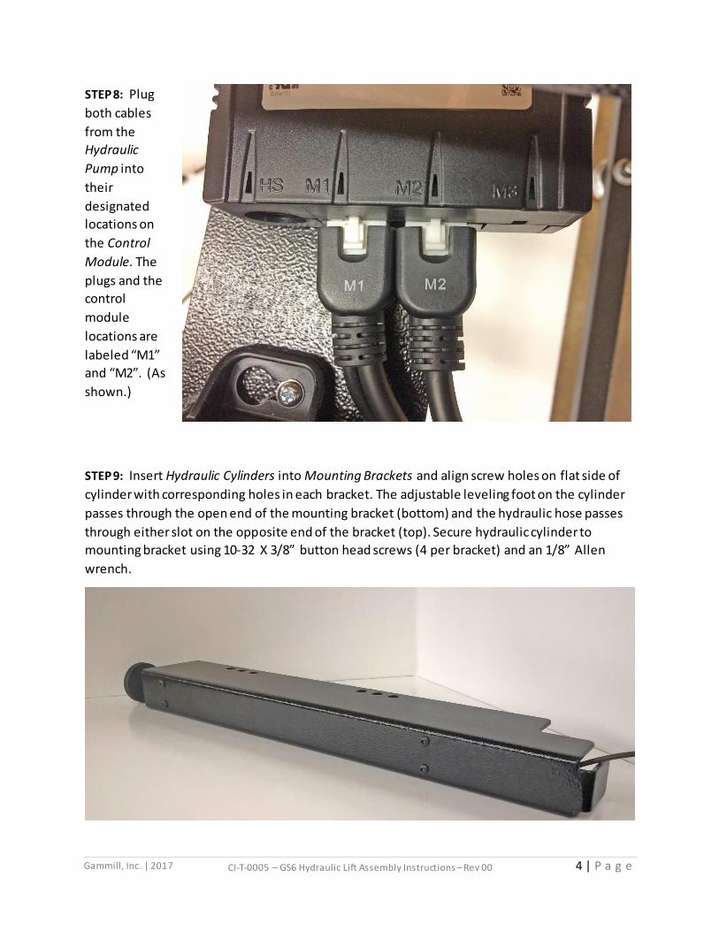
STEP 8: Plug
both cables
from the
Hydraulic
Pump into
their
designated
locations on
the Control
Module. The
plugs and the
control
module
locations are
labeled “M1”
and “M2”. (As
shown.)
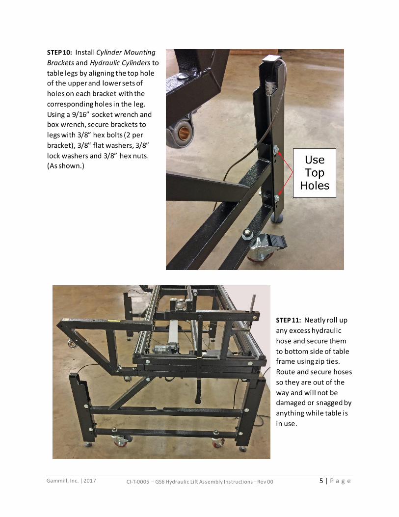
STEP 9: Insert Hydraulic Cylinders into Mounting Brackets and align screw holes on flat side of
cylinder with corresponding holes in each bracket. The adjustable leveling foot on the cylinder
passes through the open end of the mounting bracket (bottom) and the hydraulic hose passes
through either slot on the opposite end of the bracket (top). Secure hydraulic cylinder to
mounting bracket using 10-32 X 3/8” button head screws (4 per bracket) and an 1/8” Allen
wrench.
5 | P a g e
Gammill, Inc. | 2017 CI-T-0005 – GS6 Hydraulic Lift Assembly Instructions – Rev 00
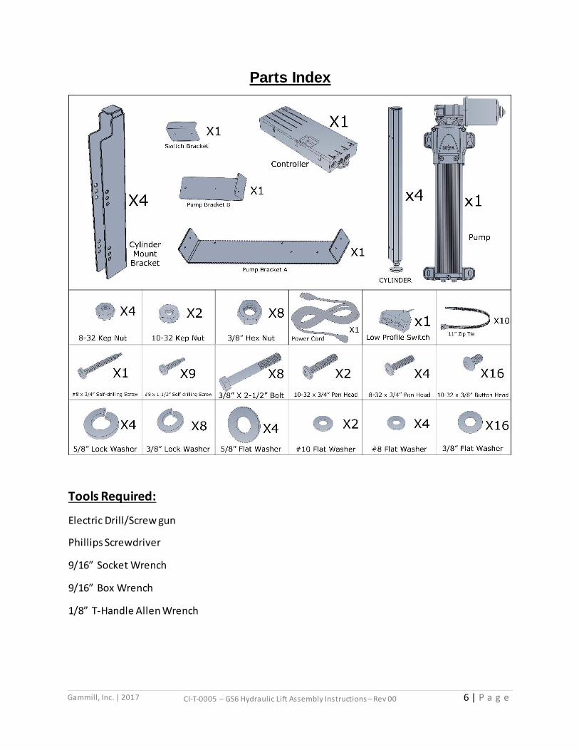
STEP 10: Install Cylinder Mounting
Brackets and Hydraulic Cylinders to
table legs by aligning the top hole
of the upper and lower sets of
holes on each bracket with the
corresponding holes in the leg.
Using a 9/16” socket wrench and
box wrench, secure brackets to
legs with 3/8” hex bolts (2 per
bracket), 3/8” flat washers, 3/8”
lock washers and 3/8” hex nuts.
(As shown.)
STEP 11: Neatly roll up
any excess hydraulic
hose and secure them
to bottom side of table
frame using zip ties.
Route and secure hoses
so they are out of the
way and will not be
damaged or snagged by
anything while table is
in use.
6 | P a g e
Gammill, Inc. | 2017 CI-T-0005 – GS6 Hydraulic Lift Assembly Instructions – Rev 00
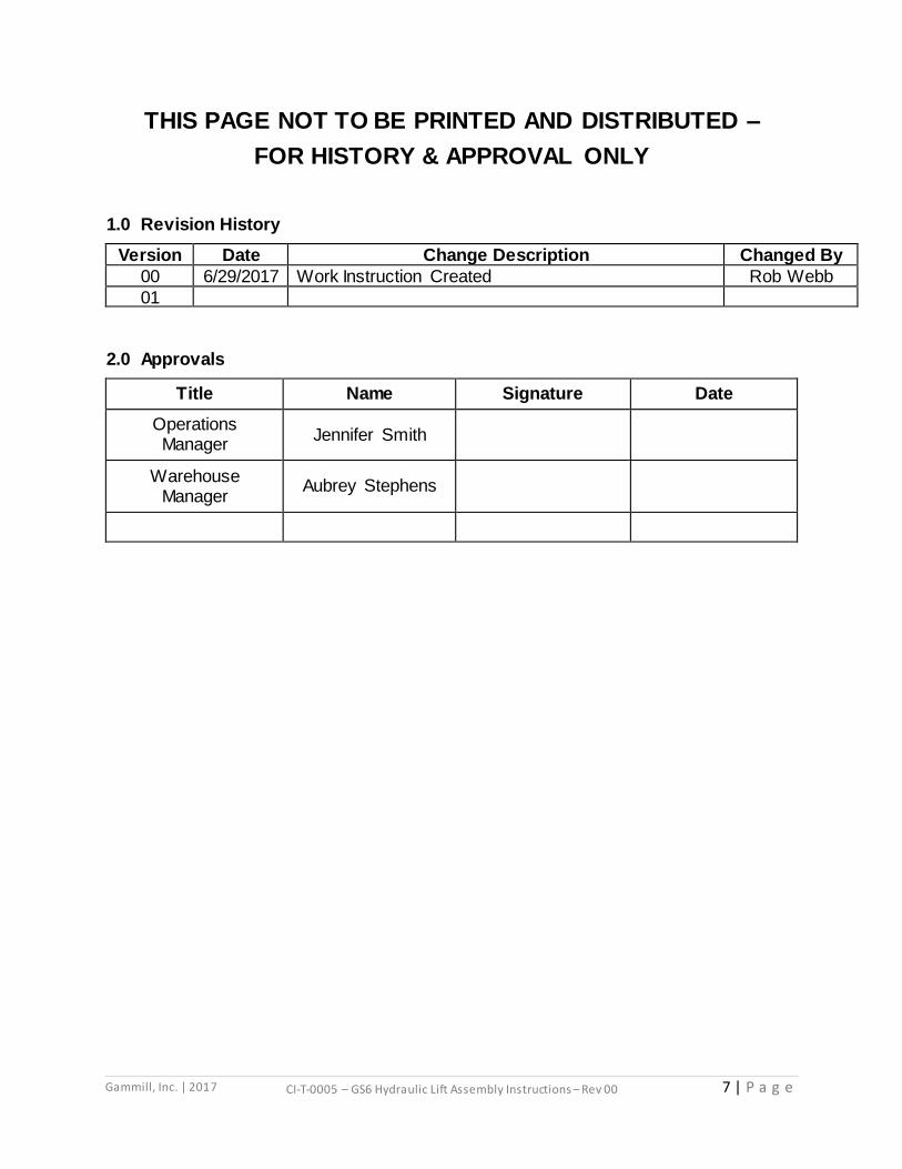
Parts Index
Tools Required:
Electric Drill/Screw gun
Phillips Screwdriver
9/16” Socket Wrench
9/16” Box Wrench
1/8” T-Handle Allen Wrench
7 | P a g e
Gammill, Inc. | 2017 CI-T-0005 – GS6 Hydraulic Lift Assembly Instructions – Rev 00
THIS PAGE NOT TO BE PRINTED AND DISTRIBUTED –
FOR HISTORY & APPROVAL ONLY
1.0 Revision History
Version Date Change Description Changed By
00 6/29/2017 Work Instruction Created Rob Webb
01
2.0 Approvals
Title Name Signature Date
Operations Manager
Jennifer Smith
Warehouse Manager
Aubrey Stephens
![fileProduct Cauliflower Onions Parsley (Herb) Peas Product Cert. No] 00064- PTKPT_ 0005 00064- PTKTF- 0005 00064- p TKNX- 0005 00064- p TKTT- 0005](https://img.pdfslide.net/doc/110x75/5e07c61b61631c3fb5083934/cauliflower-onions-parsley-herb-peas-product-cert-no-00064-ptkpt-0005-00064-.jpg)