Embed Size (px)
Citation preview
Page 1IronHorse GSDA-DP DC Drives Accessory User Manual – 1st Ed. Rev. C – 1/2016
™GSD Series DC Drives Accessory
GSDA-DP Digital Potentiometer User ManualUser Manual Number: GSDA-DP-User-M
Page 2 IronHorse GSDA-DP DC Drives Accessory User Manual – 1st Ed. Rev. C – 1/2016
~ WARNING ~ Thank you for purchasing automation equipment from Automationdirect.com®, doing business as Automation-Direct. We want your new automation equipment to operate safely. Anyone who installs or uses this equipment should read this publication (and any other relevant publications) before installing or operating the equipment.To minimize the risk of potential safety problems, you should follow all applicable local and national codes that regulate the installation and operation of your equipment. These codes vary from area to area and usually change with time. It is your responsibility to determine which codes should be followed, and to verify that the equipment, installation, and operation is in compliance with the latest revision of these codes.At a minimum, you should follow all applicable sections of the National Fire Code, National Electrical Code, and the codes of the National Electrical Manufacturer’s Association (NEMA). There may be local regulatory or government offices that can also help determine which codes and standards are necessary for safe installation and operation.Equipment damage or serious injury to personnel can result from the failure to follow all applicable codes and standards. We do not guarantee the products described in this publication are suitable for your particular application, nor do we assume any responsibility for your product design, installation, or operation.Our products are not fault-tolerant and are not designed, manufactured or intended for use or resale as on-line control equipment in hazardous environments requiring fail-safe performance, such as in the operation of nuclear facilities, aircraft navigation or communication systems, air traffic control, direct life support machines, or weapons systems, in which the failure of the product could lead directly to death, personal injury, or severe physical or environmental damage (“High Risk Activities”). AutomationDirect specifically disclaims any expressed or implied warranty of fitness for High Risk Activities.For additional warranty and safety information, see the Terms and Conditions section of our catalog. If you have any questions concerning the installation or operation of this equipment, or if you need additional information, please call us at 770-844-4200.This publication is based on information that was available at the time it was printed. At AutomationDirect we constantly strive to improve our products and services, so we reserve the right to make changes to the products and/or publications at any time without notice and without any obligation. This publication may also discuss features that may not be available in certain revisions of the product.
TrademarksThis publication may contain references to products produced and/or offered by other companies. The product and company names may be trademarked and are the sole property of their respective owners. AutomationDirect disclaims any proprietary interest in the marks and names of others.
Copyright © 2013 Automationdirect.com® IncorporatedAll Rights Reserved
No part of this manual shall be copied, reproduced, or transmitted in any way without the prior, written consent of Automationdirect.com® Incorporated. AutomationDirect retains the exclusive rights to all information included in this document.
Publication HistoryIssue Date Description
1st Edition December 2013 Initial Publication
1st Ed. Rev. B December 2013 Misc. Revisions
1st Ed. Rev. C January 2016 Added Mode 7: Parameter Lock to Parameters 30 and 35
Page 3IronHorse GSDA-DP DC Drives Accessory User Manual – 1st Ed. Rev. C – 1/2016
ContentsWARNING � � � � � � � � � � � � � � � � � � � � � � � � � � � � � � � � � � � � � � � � � � � � � � � � � � � � � � � � � � � � � � � � � 2
Trademarks � � � � � � � � � � � � � � � � � � � � � � � � � � � � � � � � � � � � � � � � � � � � � � � � � � � � � � � � � � � � � � � � 2
Publication History � � � � � � � � � � � � � � � � � � � � � � � � � � � � � � � � � � � � � � � � � � � � � � � � � � � � � � � � � � � 2
GSDA-DP Digital Potentiometer Data Sheet Overview � � � � � � � � � � � � � � � � � � � � � � � � � � � � � � � � � � � � � � � 3
IronHorse GSDA-DP Digital Potentiometer General Information � � � � � � � � � � � � � � � � � � � � � � � � � � � � � � � � 4
Specifications � � � � � � � � � � � � � � � � � � � � � � � � � � � � � � � � � � � � � � � � � � � � � � � � � � � � � � � � � � � � � � � 5
Mechanical Installation� � � � � � � � � � � � � � � � � � � � � � � � � � � � � � � � � � � � � � � � � � � � � � � � � � � � � � � � � 5
Program Jumper Setting � � � � � � � � � � � � � � � � � � � � � � � � � � � � � � � � � � � � � � � � � � � � � � � � � � � � � � � � 6
Electrical Wiring� � � � � � � � � � � � � � � � � � � � � � � � � � � � � � � � � � � � � � � � � � � � � � � � � � � � � � � � � � � � � 6
Basic Operating Information � � � � � � � � � � � � � � � � � � � � � � � � � � � � � � � � � � � � � � � � � � � � � � � � � � � � � � 8
Software Parameters � � � � � � � � � � � � � � � � � � � � � � � � � � � � � � � � � � � � � � � � � � � � � � � � � � � � � � � � � 10
Parameter Descriptions � � � � � � � � � � � � � � � � � � � � � � � � � � � � � � � � � � � � � � � � � � � � � � � � � � � � � � � � 12
Troubleshooting � � � � � � � � � � � � � � � � � � � � � � � � � � � � � � � � � � � � � � � � � � � � � � � � � � � � � � � � � � � � 20
GSDA-DP Digital Potentiometer Data Sheet OverviewOverview of this Publication
The IronHorse GSDA-DP Digital Potentiometer Data Sheet describes the installation, configuration, and methods of operation of the GSDA-DP Digital Potentiometer, which can be used with GSD Series DC Drives.All information contained in this manual is intended to be correct. However, information and data in this manual are subject to change without notice. AutomationDirect (ADC) makes no warranty of any kind with regard to this information or data. Further, ADC is not responsible for any omissions or errors or consequential damage caused by the user of the product. ADC reserves the right to make manufacturing changes which may not be included in this manual.
Who Should Read This Data Sheet
This manual contains important information for those who will install, maintain, and/or operate any of the GSDA-DP Digital Potentiometers.
Technical Support
By Telephone: 770-844-4200 (Mon.–Fri., 9:00 a.m.–6:00 p.m. E.T.)On the Web: www.automationdirect.comOur technical support group is glad to work with you in answering your questions. If you cannot find the solution to your particular application, or, if for any reason you need additional technical assistance, please call Technical Support at 770-844-4200. We are available weekdays from 9:00 a.m. to 6:00 p.m. Eastern Time.We also encourage you to visit our web site where you can find technical and non-technical information about our products and our company. Visit us at www.automationdirect.com.
Special Symbols
When you see the “notepad” icon in the left-hand margin, the paragraph to its immediate right will be a special note.
When you see the “exclamation mark” icon in the left-hand margin, the paragraph to its immediate right Will be a Warning. this information could prevent injury, loss of property, or even death (in extreme cases).
Page 4 IronHorse GSDA-DP DC Drives Accessory User Manual – 1st Ed. Rev. C – 1/2016
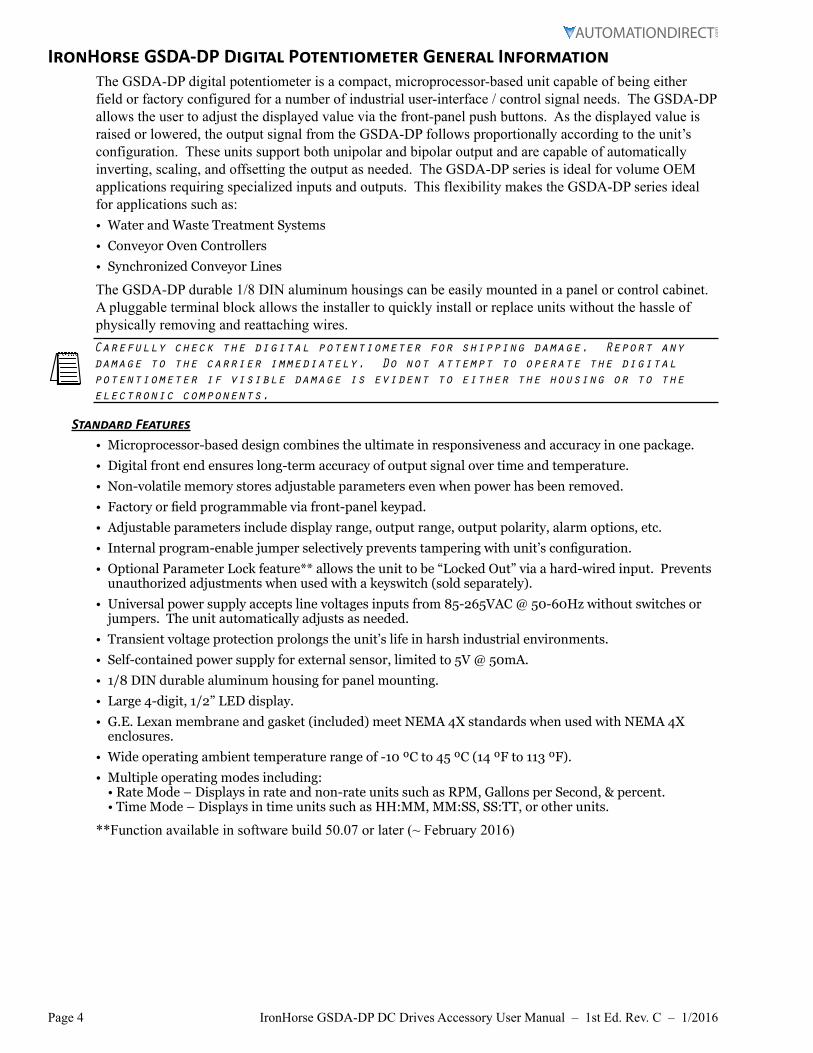
IronHorse GSDA-DP Digital Potentiometer General InformationThe GSDA-DP digital potentiometer is a compact, microprocessor-based unit capable of being either field or factory configured for a number of industrial user-interface / control signal needs. The GSDA-DP allows the user to adjust the displayed value via the front-panel push buttons. As the displayed value is raised or lowered, the output signal from the GSDA-DP follows proportionally according to the unit’s configuration. These units support both unipolar and bipolar output and are capable of automatically inverting, scaling, and offsetting the output as needed. The GSDA-DP series is ideal for volume OEM applications requiring specialized inputs and outputs. This flexibility makes the GSDA-DP series ideal for applications such as:• Water and Waste Treatment Systems
• Conveyor Oven Controllers
• Synchronized Conveyor Lines
The GSDA-DP durable 1/8 DIN aluminum housings can be easily mounted in a panel or control cabinet. A pluggable terminal block allows the installer to quickly install or replace units without the hassle of physically removing and reattaching wires.Carefully check the digital potentiometer for shipping damage. Report any damage to the carrier immediately. Do not attempt to operate the digital potentiometer if visible damage is evident to either the housing or to the electronic components.
Standard Features• Microprocessor-based design combines the ultimate in responsiveness and accuracy in one package.
• Digital front end ensures long-term accuracy of output signal over time and temperature.
• Non-volatile memory stores adjustable parameters even when power has been removed.
• Factory or field programmable via front-panel keypad.
• Adjustable parameters include display range, output range, output polarity, alarm options, etc.
• Internal program-enable jumper selectively prevents tampering with unit’s configuration.
• Optional Parameter Lock feature** allows the unit to be “Locked Out” via a hard-wired input. Prevents unauthorized adjustments when used with a keyswitch (sold separately).
• Universal power supply accepts line voltages inputs from 85-265VAC @ 50-60Hz without switches or jumpers. The unit automatically adjusts as needed.
• Transient voltage protection prolongs the unit’s life in harsh industrial environments.
• Self-contained power supply for external sensor, limited to 5V @ 50mA.
• 1/8 DIN durable aluminum housing for panel mounting.
• Large 4-digit, 1/2” LED display.
• G.E. Lexan membrane and gasket (included) meet NEMA 4X standards when used with NEMA 4X enclosures.
• Wide operating ambient temperature range of -10 ºC to 45 ºC (14 ºF to 113 ºF).
• Multiple operating modes including: • Rate Mode – Displays in rate and non-rate units such as RPM, Gallons per Second, & percent. • Time Mode – Displays in time units such as HH:MM, MM:SS, SS:TT, or other units.
**Function available in software build 50.07 or later (~ February 2016)
Page 5IronHorse GSDA-DP DC Drives Accessory User Manual – 1st Ed. Rev. C – 1/2016
SpecificationsGSDA-DP – Specifications
Electrical
Line Input Voltage 85–265 VAC
Line Input Frequency 48–62 Hz
Display Range 0.001 – 9999
Units of Operation User Programmable, any Unit
On-board Power Supply (Externally Accessible) 5V @ 50mA
Pot Lo/Hi supply VDC range 0–2 VDC through 0–24 VDC
Pot wiper VDC range Pot Lo +50mV through Pot Hi -50mV
Pot circuit current draw 2mA @ 12V
Pot circuit isolation >500MΩ
Isolated Alarm Relay Output Ratings 250VAC @ 5A; Form C
Resolution of D-A converter 10 bits
Analog Output Any unipolar or bipolar voltage range (based on input voltage) up to 24VDC
Mechanical
Display Type LED, Red, 4-Digit, 1/2 inch Height
Housing Type (with supplied gasket in NEMA 4X panel) 1/8 DIN NEMA 4X
Connector Style 12-position 5mm European Style
Terminal Block Torque Setting 4.4 lb·in Max [0.5 N·m]
Faceplate Material Polycarbonate with GE Lexan Overlay
Housing Material Aluminum
Weight 14.4 oz [408.22g]
EnvironmentalOperating Temperature Range -10 °C to 45 °C [14 °F to 113 °F]
Operating Humidity Range 95% non-condensing
Regulatory Agency Approvals RoHS
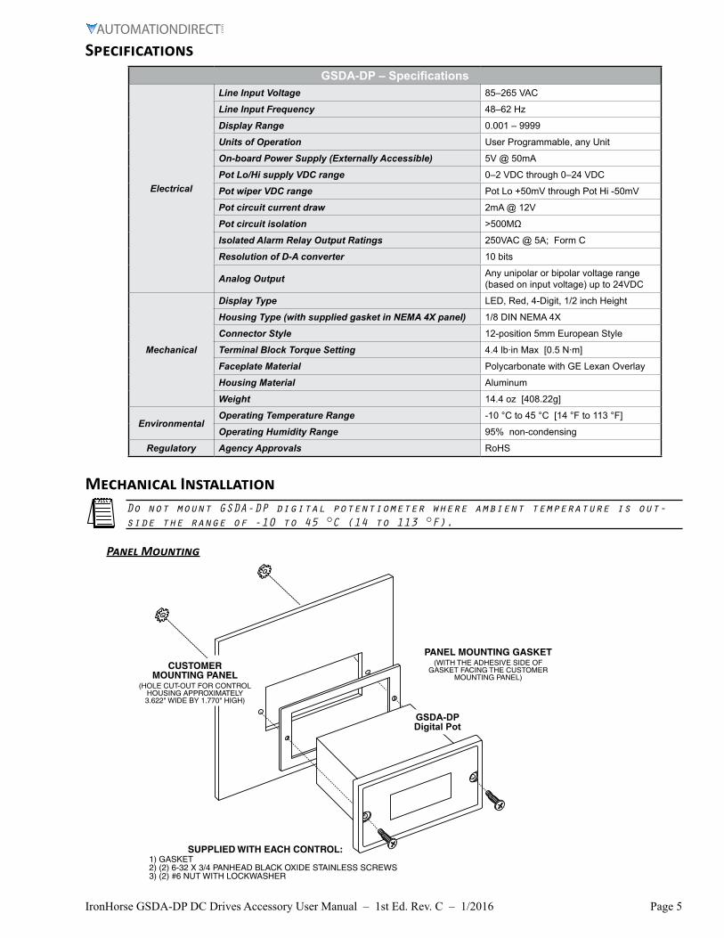
Mechanical InstallationDo not mount GSDA-DP digital potentiometer where ambient temperature is out-side the range of -10 to 45 °C (14 to 113 °F).
Panel Mounting
PANEL MOUNTING GASKET(WITH THE ADHESIVE SIDE OF
GASKET FACING THE CUSTOMER MOUNTING PANEL)
CUSTOMERMOUNTING PANEL
(HOLE CUT-OUT FOR CONTROLHOUSING APPROXIMATELY3.622" WIDE BY 1.770" HIGH)
GSDA-DPDigital Pot
SUPPLIED WITH EACH CONTROL: 1) GASKET 2) (2) 6-32 X 3/4 PANHEAD BLACK OXIDE STAINLESS SCREWS 3) (2) #6 NUT WITH LOCKWASHER
Page 6 IronHorse GSDA-DP DC Drives Accessory User Manual – 1st Ed. Rev. C – 1/2016
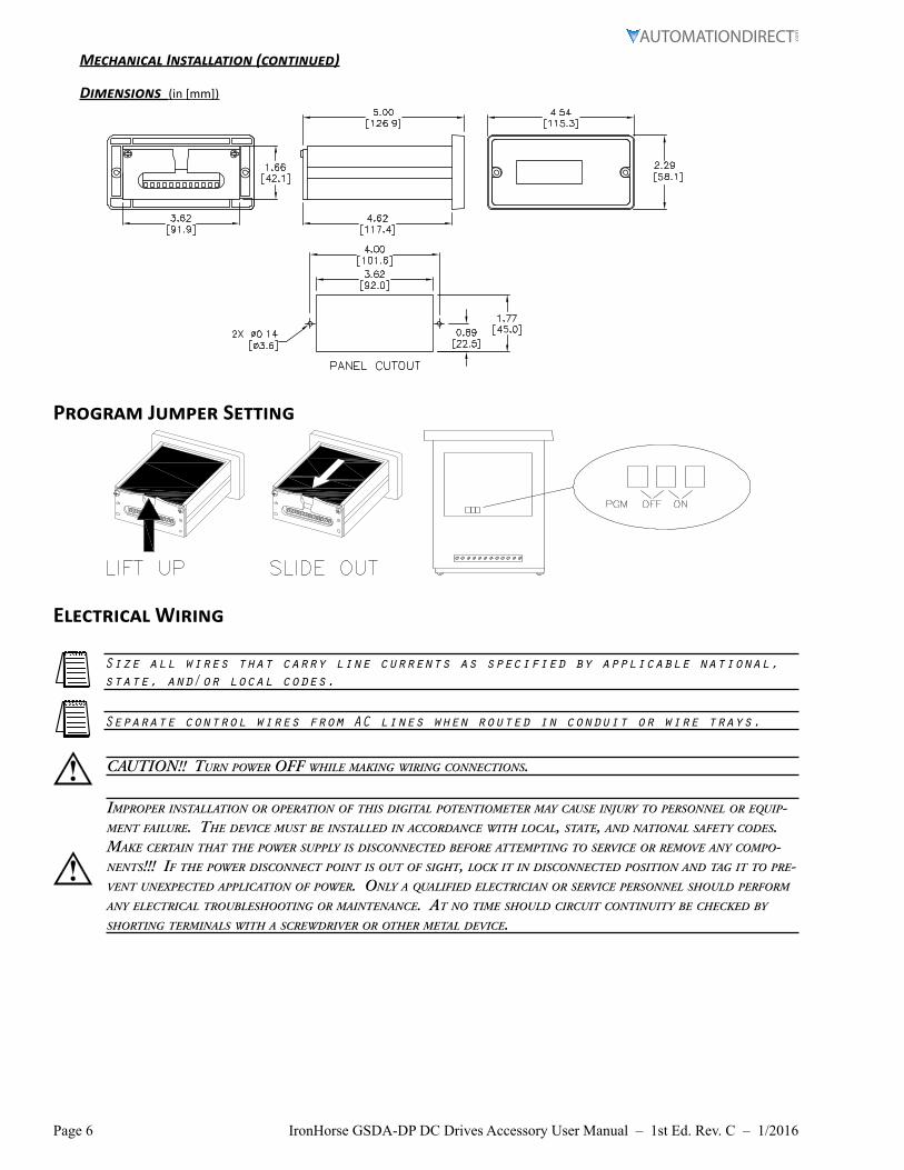
Mechanical Installation (continued)
Dimensions (in [mm])
Program Jumper Setting
Electrical Wiring
Size all wires that carry line currents as specified by applicable national, state, and/or local codes.
Separate control wires from AC lines when routed in conduit or wire trays.
caution!! turn poWer off While making Wiring connections.
improper installation or operation of this digital potentiometer may cause injury to personnel or equip-ment failure. the device must be installed in accordance With local, state, and national safety codes. make certain that the poWer supply is disconnected before attempting to service or remove any compo-nents!!! if the poWer disconnect point is out of sight, lock it in disconnected position and tag it to pre-vent unexpected application of poWer. only a qualified electrician or service personnel should perform any electrical troubleshooting or maintenance. at no time should circuit continuity be checked by shorting terminals With a screWdriver or other metal device.
Page 7IronHorse GSDA-DP DC Drives Accessory User Manual – 1st Ed. Rev. C – 1/2016
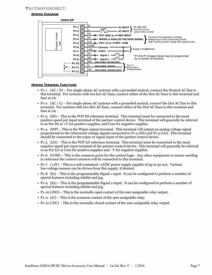
Wiring Diagram
2 AMP }
} Form CRelay output(Programmable)
Alarm Output - Normally Open
Alarm Output - Common
Alarm Output - Normally Closed
*
*
}* P1-8 & P1-9 signal inputs may be programmed for a number of functions.
GSDA-DP
Supply (+5V@50mA)
AC INPUTAC INPUT
Common+5VDC
Signal 1Signal 2
85–265 VACfuse both lines for system without neutral
Pro
gram
Jum
per
P1-1P1-2P1-3P1-4P1-5P1-6P1-7P1-8P1-9
P1-10P1-11P1-12
NLHIWLOCOM+5VS1S2NOCNC
}POT HIGH or +V REF INPUTWIPER or ANALOG VOLTAGE SIGNALPOT LO or -V REF / COM
Connect to the Speedpot or Analog Voltage Input of the control being driven.High must be positive voltage with respect to low.
Wiring Terminal Functions• P1-1 (AC / N) – For single-phase AC systems with a grounded neutral, connect the Neutral AC line to
this terminal. For systems with two hot AC lines, connect either of the Hot AC lines to this terminal and fuse at 2A.
• P1-2 (AC / L) – For single-phase AC systems with a grounded neutral, connect the Hot AC line to this terminal. For systems with two Hot AC lines, connect either of the Hot AC lines to this terminal and fuse at 2A.
• P1-3 (HI) – This is the POT HI reference terminal. This terminal must be connected to the most positive speed pot input terminal of the partner control device. This terminal will generally be referred to as Pot HI or +V for positive supplies, and Com for negative supplies.
• P1-4 (WP) – This is the Wiper output terminal. This terminal will output an analog voltage signal proportional to the referenced voltage signals connected to P1-3 (HI) and P1-5 (LO). This terminal should be connected to the wiper or signal input of the partner control device.
• P1-5 (LO) – This is the POT LO reference terminal. This terminal must be connected to the most negative speed pot input terminal of the partner control device. This terminal will generally be referred to as Pot LO or Com for positive supplies and –V for negative supplies.
• P1-6 (COM) – This is the common point for the control logic. Any other equipment or source needing to reference the control common will be connected to this terminal.
• P1-7 (+5V) – This is a self-contained +5VDC power supply capable of up to 50 mA. Various low-voltage sensors can be driven from this supply, if desired.
• P1-8 (S1) – This is the programmable Signal 1 input. It can be configured to perform a number of special features including inhibit and jog.
• P1-9 (S2) – This is the programmable Signal 2 input. It can be configured to perform a number of special features including inhibit and jog.
• P1-10 (1NO) – This is the normally-open contact of the user assignable relay output.
• P1-11 (1C) – This is the common contact of the user assignable relay.
• P1-12 (1NC) – This is the normally-closed contact of the user assignable relay output.
Page 8 IronHorse GSDA-DP DC Drives Accessory User Manual – 1st Ed. Rev. C – 1/2016
Basic Operating InformationThe GSDA-DP digital potentiometer is a panel-mount digital-to-analog user interface. Put simply, it allows the user to adjust the displayed value via push buttons on the front panel; and it outputs a proportional signal according to its configuration. It can be configured to work with both single and bidirectional partner drives. It also supports both unipolar and bipolar output supplies.The GSDA-DP can display values in rate and time formats.• In Rate mode, output units such as Gallons-per-Minutes, RPM, and Percent are possible with just a few
minor adjustments. (A set value of 200 will output twice as much voltage as a set value of 100.)
• In Time mode, output units such as Hours:Minutes (HH:MM), Minutes:Seconds (MM:SS), and Seconds:Ticks (SS:TT) are supported. In Time modes, the output will be inversely proportional to the displayed value in order to represent a programmable process time. (A set time of 1:20 will output twice as much voltage as a set time of 2:40.)
Rate and Time mode cycle times operate inversely from each other:
Output %Min (P25)
Output %Max (P26)
Display ValueMin (P20)
Display ValueMax (P21)
GSDA-DP Setting (%)
GS
DA
-DP
Out
put (
V)
Rate Mode, Unipolar Output Time Mode, Unipolar Output
Output %Min (P25)
Output %Max (P26)
Display Value Min(P20)
Display Value Max
(P21)GSDA-DP Setting (min:sec)
GS
DA
-DP
Out
put (
V)
Rate Mode Example: The GSDA-DP is wired to a +12 VDC Voltage Reference (Pot High supply). This will control a drive that accepts a 12 VDC signal input. The driven motor has a rated speed of 1800 rpm. For the operator to display/control the motor in rpm, set parameters as follows:• P10 (Operating Mode) = 1 (Unipolar Rate Mode)
• P12 (Display Zero Blanking) = 4 (show 4 digits) The actual number of digits that will appear on the operating display.
• P13 (Decimal point) = 3 (no decimal precision)
• P20 (Display Min Value) = 0
• P21 (Display Max Value) = 1800
• P25 (Output % Min) = 0
• P26 (Output % Max) = 1000 (100%.) (P25 and P26 are set in tenths of a %)
0 VDC
12 VDC
0 rpm 1800 rpmGSDA-DP Setting (%)
GS
DA
-DP
Out
put (
V)
Rate Mode, Unipolar Output
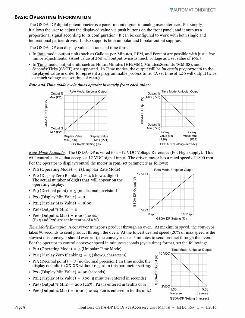
Time Mode Example: A conveyor transports product through an oven. At maximum speed, the conveyor takes 90 seconds to send product through the oven. At the lowest desired speed (20% of max speed is the slowest this conveyor should ever run), the conveyor takes 5 minutes to send product through the oven. For the operator to control conveyor speed in minutes:seconds (cycle time) format, set the following:• P10 (Operating Mode) = 5 (Unipolar Time Mode)
• P12 (Display Zero Blanking) = 3 (show 3 characters)
• P13 (Decimal point) = 3 (no decimal precision) In time mode, the display defaults to XX:XX without regard to this parameter setting.
• P20 (Display Min Value) = 90 (seconds)
• P21 (Display Max Value) = 300 (5 minutes, entered in seconds)
• P25 (Output % Min) = 200 (20%; P25 is entered in tenths of %)
• P26 (Output % Max) = 1000 (100%; P26 is entered in tenths of %)
Time Mode, Unipolar Output
2VDC
10 VDC
1:30traverse
5:00traverse
GSDA-DP Setting (min:sec)
GS
DA
-DP
Out
put (
V)
Page 9IronHorse GSDA-DP DC Drives Accessory User Manual – 1st Ed. Rev. C – 1/2016
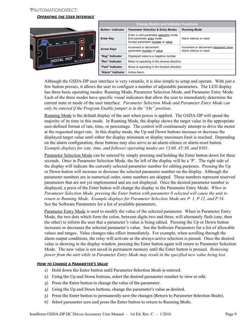
Operating the User Interface
Display Button and Indicator FunctionsButton / Indicator Parameter Selection & Entry Modes Running Mode
Enter KeyEnter or exit parameter selection modeExit parameter entry mode Accept parameter number or value
Alarm silence or reset
Arrow Keys Increment or decrement parameter number or value
Increment or decrement displayed valueAlarm silence or reset
“Neg” Indicator Displayed value is a negative number
“Rev” Indicator Motor is operating in the reverse direction
“Fwd” Indicator Motor is operating in the forward direction
“Alarm” Indicator Active Alarm
Although the GSDA-DP user interface is very versatile, it is also simple to setup and operate. With just a few button presses, it allows the user to configure a number of adjustable parameters. The LED display has three basic operating modes: Running Mode, Parameter Selection Mode, and Parameter Entry Mode. Each of the three modes have specific visual indicators that allow the user to immediately determine the current state or mode of the user interface. Parameter Selection Mode and Parameter Entry Mode can only be entered if the Program Enable jumper is in the “On” position.Running Mode is the default display of the unit when power is applied. The GSDA-DP will spend the majority of its time in this mode. In Running Mode, the display shows the target value in the appropriate user-defined format of rate, time, or percentage. The control will continuously attempt to drive the motor at the requested target rate. In this display mode, the Up and Down buttons increase or decrease the displayed target value until either the display minimum or display maximum limit is reached. Depending on the alarm configuration, these buttons may also serve as an alarm-silence or alarm-reset button. Example displays for rate, time, and follower operating modes are 13.60, 45:30, and 9301.Parameter Selection Mode can be entered by simply pressing and holding the Enter button down for three seconds. Once in Parameter Selection Mode, the far left of the display will be a ‘P’. The right side of the display will indicate the currently selected parameter number for editing purposes. Pressing the Up or Down button will increase or decrease the selected parameter number on the display. Although the parameter numbers are in numerical order, some numbers are skipped. These numbers represent reserved parameters that are not yet implemented and are not displayed. Once the desired parameter number is displayed, a press of the Enter button will change the display to the Parameter Entry Mode. When in Parameter Selection Mode, pressing the Enter button with parameter 0 selected will cause the unit to return to Running Mode. Example displays for Parameter Selection Mode are P 1, P 12, and P 54. See the Software Parameters for a list of available parameters.Parameter Entry Mode is used to modify the value of the selected parameter. When in Parameter Entry Mode, the two dots which form the colon, between digits two and three, will alternately flash (one, then the other) to inform the user that a parameter’s value is being edited. Pressing the Up or Down button increases or decreases the selected parameter’s value. See the Software Parameters for a list of allowable values and ranges. Value changes take effect immediately. For example, when scrolling through the alarm output conditions, the relay will activate as the always-active selection is passed. Once the desired value is showing in the display window, pressing the Enter button again will return to Parameter Selection Mode. The new value is not saved in permanent memory until the Enter button is pressed. Removing power from the unit while in Parameter Entry Mode may result in the specified new value being lost.
How to Change a Parameter’s Value1) Hold down the Enter button until Parameter Selection Mode is entered.
2) Using the Up and Down buttons, select the desired parameter number to view or edit.
3) Press the Enter button to change the value of the parameter.
4) Using the Up and Down buttons, change the parameter’s value as desired.
5) Press the Enter button to permanently save the changes (Return to Parameter Selection Mode).
6) Select parameter zero and press the Enter button to return to Running Mode.
Page 10 IronHorse GSDA-DP DC Drives Accessory User Manual – 1st Ed. Rev. C – 1/2016
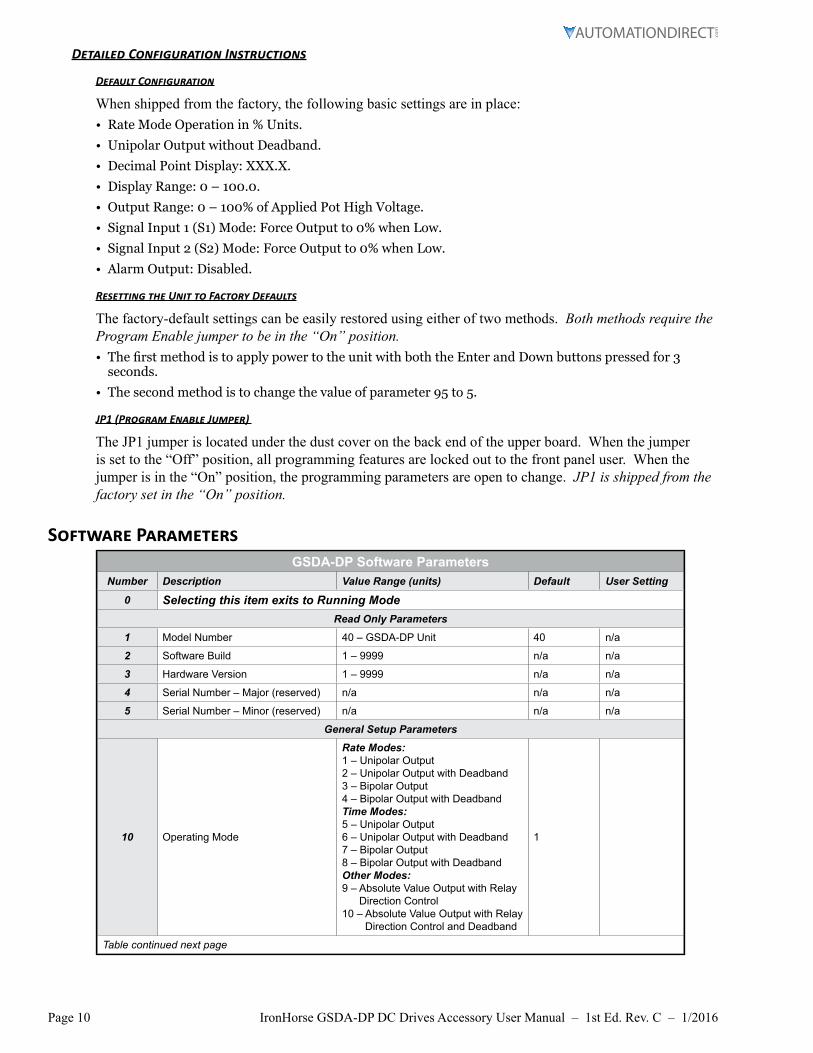
Detailed Configuration Instructions
Default Configuration
When shipped from the factory, the following basic settings are in place:• Rate Mode Operation in % Units.
• Unipolar Output without Deadband.
• Decimal Point Display: XXX.X.
• Display Range: 0 – 100.0.
• Output Range: 0 – 100% of Applied Pot High Voltage.
• Signal Input 1 (S1) Mode: Force Output to 0% when Low.
• Signal Input 2 (S2) Mode: Force Output to 0% when Low.
• Alarm Output: Disabled.
Resetting the Unit to Factory Defaults
The factory-default settings can be easily restored using either of two methods. Both methods require the Program Enable jumper to be in the “On” position.• The first method is to apply power to the unit with both the Enter and Down buttons pressed for 3
seconds.
• The second method is to change the value of parameter 95 to 5.
JP1 (Program Enable Jumper)
The JP1 jumper is located under the dust cover on the back end of the upper board. When the jumper is set to the “Off” position, all programming features are locked out to the front panel user. When the jumper is in the “On” position, the programming parameters are open to change. JP1 is shipped from the factory set in the “On” position.
Software ParametersGSDA-DP Software Parameters
Number Description Value Range (units) Default User Setting
0 Selecting this item exits to Running ModeRead Only Parameters
1 Model Number 40 – GSDA-DP Unit 40 n/a
2 Software Build 1 – 9999 n/a n/a
3 Hardware Version 1 – 9999 n/a n/a
4 Serial Number – Major (reserved) n/a n/a n/a
5 Serial Number – Minor (reserved) n/a n/a n/a
General Setup Parameters
10 Operating Mode
Rate Modes:1 – Unipolar Output2 – Unipolar Output with Deadband3 – Bipolar Output4 – Bipolar Output with DeadbandTime Modes:5 – Unipolar Output6 – Unipolar Output with Deadband7 – Bipolar Output8 – Bipolar Output with DeadbandOther Modes:9 – Absolute Value Output with Relay
Direction Control10 – Absolute Value Output with Relay
Direction Control and Deadband
1
Table continued next page
Page 11IronHorse GSDA-DP DC Drives Accessory User Manual – 1st Ed. Rev. C – 1/2016
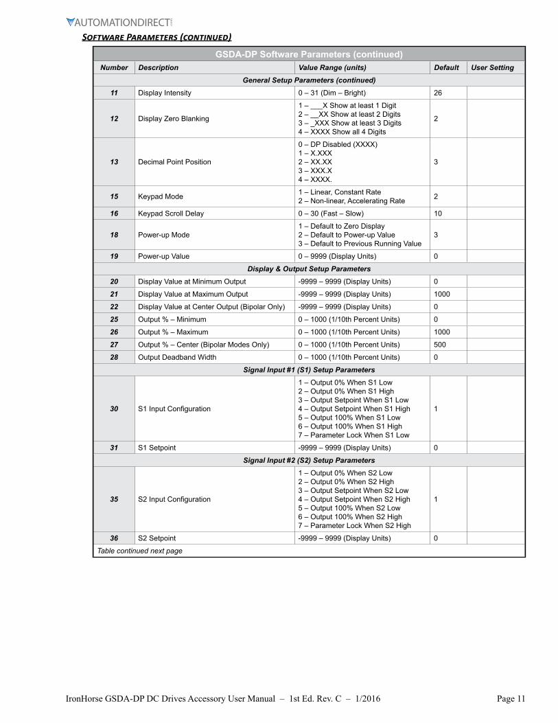
Software Parameters (continued)
GSDA-DP Software Parameters (continued)Number Description Value Range (units) Default User Setting
General Setup Parameters (continued)
11 Display Intensity 0 – 31 (Dim – Bright) 26
12 Display Zero Blanking
1 – ___X Show at least 1 Digit2 – __XX Show at least 2 Digits3 – _XXX Show at least 3 Digits4 – XXXX Show all 4 Digits
2
13 Decimal Point Position
0 – DP Disabled (XXXX)1 – X.XXX2 – XX.XX3 – XXX.X4 – XXXX.
3
15 Keypad Mode 1 – Linear, Constant Rate2 – Non-linear, Accelerating Rate 2
16 Keypad Scroll Delay 0 – 30 (Fast – Slow) 10
18 Power-up Mode1 – Default to Zero Display2 – Default to Power-up Value3 – Default to Previous Running Value
3
19 Power-up Value 0 – 9999 (Display Units) 0
Display & Output Setup Parameters
20 Display Value at Minimum Output -9999 – 9999 (Display Units) 0
21 Display Value at Maximum Output -9999 – 9999 (Display Units) 1000
22 Display Value at Center Output (Bipolar Only) -9999 – 9999 (Display Units) 0
25 Output % – Minimum 0 – 1000 (1/10th Percent Units) 0
26 Output % – Maximum 0 – 1000 (1/10th Percent Units) 1000
27 Output % – Center (Bipolar Modes Only) 0 – 1000 (1/10th Percent Units) 500
28 Output Deadband Width 0 – 1000 (1/10th Percent Units) 0
Signal Input #1 (S1) Setup Parameters
30 S1 Input Configuration
1 – Output 0% When S1 Low2 – Output 0% When S1 High3 – Output Setpoint When S1 Low4 – Output Setpoint When S1 High5 – Output 100% When S1 Low6 – Output 100% When S1 High7 – Parameter Lock When S1 Low
1
31 S1 Setpoint -9999 – 9999 (Display Units) 0
Signal Input #2 (S2) Setup Parameters
35 S2 Input Configuration
1 – Output 0% When S2 Low2 – Output 0% When S2 High3 – Output Setpoint When S2 Low4 – Output Setpoint When S2 High5 – Output 100% When S2 Low6 – Output 100% When S2 High7 – Parameter Lock When S2 High
1
36 S2 Setpoint -9999 – 9999 (Display Units) 0
Table continued next page
Page 12 IronHorse GSDA-DP DC Drives Accessory User Manual – 1st Ed. Rev. C – 1/2016
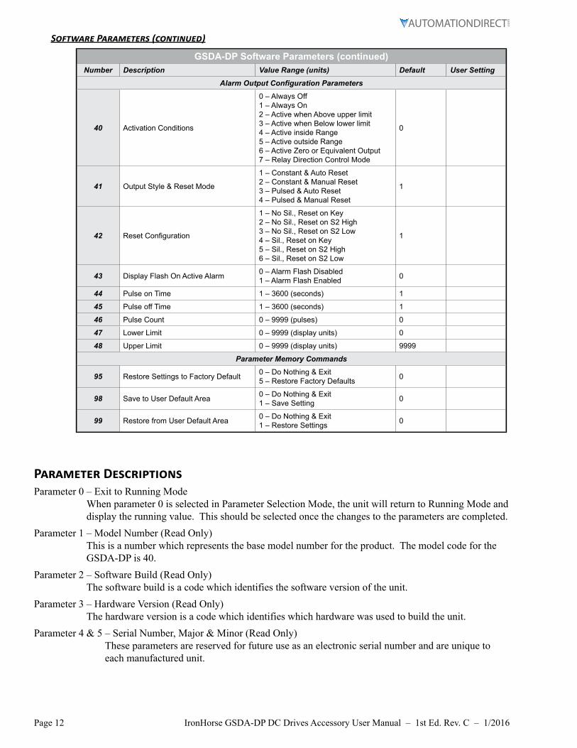
Software Parameters (continued)
GSDA-DP Software Parameters (continued)Number Description Value Range (units) Default User Setting
Alarm Output Configuration Parameters
40 Activation Conditions
0 – Always Off1 – Always On2 – Active when Above upper limit3 – Active when Below lower limit4 – Active inside Range5 – Active outside Range6 – Active Zero or Equivalent Output7 – Relay Direction Control Mode
0
41 Output Style & Reset Mode
1 – Constant & Auto Reset2 – Constant & Manual Reset3 – Pulsed & Auto Reset4 – Pulsed & Manual Reset
1
42 Reset Configuration
1 – No Sil., Reset on Key2 – No Sil., Reset on S2 High3 – No Sil., Reset on S2 Low4 – Sil., Reset on Key5 – Sil., Reset on S2 High6 – Sil., Reset on S2 Low
1
43 Display Flash On Active Alarm 0 – Alarm Flash Disabled1 – Alarm Flash Enabled 0
44 Pulse on Time 1 – 3600 (seconds) 1
45 Pulse off Time 1 – 3600 (seconds) 1
46 Pulse Count 0 – 9999 (pulses) 0
47 Lower Limit 0 – 9999 (display units) 0
48 Upper Limit 0 – 9999 (display units) 9999
Parameter Memory Commands
95 Restore Settings to Factory Default 0 – Do Nothing & Exit5 – Restore Factory Defaults 0
98 Save to User Default Area 0 – Do Nothing & Exit1 – Save Setting 0
99 Restore from User Default Area 0 – Do Nothing & Exit1 – Restore Settings 0
Parameter DescriptionsParameter 0 – Exit to Running Mode
When parameter 0 is selected in Parameter Selection Mode, the unit will return to Running Mode and display the running value. This should be selected once the changes to the parameters are completed.
Parameter 1 – Model Number (Read Only) This is a number which represents the base model number for the product. The model code for the GSDA-DP is 40.
Parameter 2 – Software Build (Read Only) The software build is a code which identifies the software version of the unit.
Parameter 3 – Hardware Version (Read Only) The hardware version is a code which identifies which hardware was used to build the unit.
Parameter 4 & 5 – Serial Number, Major & Minor (Read Only) These parameters are reserved for future use as an electronic serial number and are unique to each manufactured unit.
Page 13IronHorse GSDA-DP DC Drives Accessory User Manual – 1st Ed. Rev. C – 1/2016
Parameter Descriptions (continued)
Parameter 10 – Operating Mode This parameter defines the operating mode for the entire unit. There are two basic modes of operation, Rate and Time. In Rate modes, the unit displays in rate and non-time-based units such as RPM, Gallons per Hour, and Percent of Maximum Output. In Time modes, the unit displays in time-based units using the format AA:BB. The AA:BB format can be adjusted to represent Hours:Minutes or Minutes:Seconds.
• Mode 1 – Rate Mode, Unipolar Output
• Mode 2 – Rate Mode, Unipolar Output with Deadband
• Mode 3 – Rate Mode, Bipolar Output
• Mode 4 – Rate Mode, Bipolar Output with Deadband
• Mode 5 – Time Mode, Unipolar Output
• Mode 6 – Time Mode, Unipolar Output with Deadband
• Mode 7 – Time Mode, Bipolar Output
• Mode 8 – Time Mode, Bipolar Output with Deadband
• Mode 9 – Other Mode, Absolute Value Output with Relay Direction Control This mode allows the GSDA-DP to interface with bi-directional Controls that have FWD and REV command inputs and use the absolute value of the pot to determine speed only. In this mode, the user must configure the following parameter:
• Display Min, Max, and Center
• Output Min and Max
• Output Deadband (Mode 10 Only!)
• Mode 10 – Other Mode, Absolute Value Output with Relay Direction Control and with Deadband Function Same as Mode 9, except deadband is supported. Must set Deadband value at Item 28.
Parameter 11 – Display Intensity This parameter adjusts the intensity of the LED display digits in the front panel of the unit. The values of 0 – 31 correspond to a gradual change from very dim to very bright. This is often useful when the GSDA-DP is used in the same panel as other pieces of equipment with LED display and a uniform display brightness is desired. Simply adjust the GSDA-DP to match its surroundings.
Parameter 12 – Display Zero Blanking This selects the number of display digits that are required to be displayed regardless of the display value. For example, with a Display Zero Blanking setting of 3 and a displayed value of 6, the display would show “_006”.
• Mode 1: ___X – Always show at least 1 digit
• Mode 2: __XX – Always show at least 2 digits
• Mode 3: _XXX – Always show at least 3 digits
• Mode 4: XXXX – Always show all 4 digits
Parameter 13 – Decimal Point (DP) Position This selects the format of the display with respect to the decimal point’s position. This parameter does not affect the value entry for other parameters. The decimal point is only displayed in Rate modes. For example, if the user desires to display numbers such as 12.34 or 1.05, then parameter 13 should be set to 2.
• Mode 0: Fixed XXXX (DP disabled)
• Mode 1: Fixed X.XXX
• Mode 2: Fixed XX.XX
• Mode 3: Fixed XXX.X
• Mode 4: Fixed XXXX.
Page 14 IronHorse GSDA-DP DC Drives Accessory User Manual – 1st Ed. Rev. C – 1/2016
Parameter Descriptions (continued)
Parameter 15 – Keypad Mode This parameter selects the operating mode of the front-panel push buttons. In some applications, increasing or decreasing the scroll rate provides the user more controllability when entering settings. Parameters 14 and 15 affect only the Up and Down buttons when the user interface is in Running Mode. These settings also apply to remote Up / Down buttons which are attached via the -1 option board.
• Mode 1: Linear, Constant Rate In linear mode, pressing and holding the Up or Down buttons will cause the display to continuously change value in the requested direction until either the Display Minimum or Display Maximum is reached. The displayed value will scroll at a constant rate which is specified using parameter 16.
• Mode 2: Non-linear, Accelerating Rate In non-linear mode, pressing and holding the Up or Down buttons will cause the display to continuously change value in the requested direction until either the Display Minimum or Display Maximum is reached. The displayed value will initially scroll at a slow rate and increase in speed until the maximum scroll rate is achieved. The initial scroll rate is specified using parameter 16.
Parameter 16 – Keypad Scroll Mode This parameter sets the scroll speed for the front-panel push buttons. The function of this parameter varies slightly depending on the Keypad Mode. See parameter 15 for more details.
Parameter 18 – Power-Up Mode This parameter defines the mode which determines the default Running Value when power is initially applied to the GSDA-DP.
• Mode 1: Default to Zero When in this mode, the unit will default to zero (display units).
• Mode 2: Default to Power-Up Value When in this mode, the unit will default to the Power-up Value, parameter 19.
• Mode 3: Default to Previously Running Value When in this mode, the unit will default to the previous running value before power was removed. A previous running value must have been active for at least 3 seconds to be recalled after power has been disconnected and reapplied.
Parameter 19 – Power-Up Value When Power-up Mode is set to 2, this parameter will designate the default display value at power-up in display units.
Parameter 20 – Display Value at Minimum Output This parameter defines the lower end of the display range. This is the value which limits how low the user is able to scroll the displayed value in Running Mode. In Rate and Time modes, this value is set in display units. This parameter is set without consideration for the decimal point’s position. For example, setting this parameter to 125 would set the lower display limit at 12.5, 0.125, or 125 seconds according to the other configuration parameters.
Parameter 21 – Display Value at Maximum Output This parameter defines the upper end of the display range. This is the value which limits how high the user is able to scroll the displayed value in Running Mode. In Rate and Time modes, this value is set in display units. This parameter is set without consideration for the decimal point’s position. For example, setting this parameter to 1000 would set the upper display limit at 100.0, 1.000, or 1000 seconds according to the other configuration parameters.
Page 15IronHorse GSDA-DP DC Drives Accessory User Manual – 1st Ed. Rev. C – 1/2016
Parameter Descriptions (continued)
Parameter 22 – Display Value at Center Output This defines the center value for the display in bipolar (or bidirectional) modes of operation. In bipolar applications, this value should be set to the display value that corresponds to a null or zero output. When in Running Mode, display values above this will produce an output toward the programmed Maximum Output %; whereas, display values below this will produce an output toward the programmed Minimum Output %. As the display value approaches the number programmed in this parameter, the GSDA-DP will produce an output that approaches the percentage programmed in parameter 28. See parameters 25 – 27 for additional information.
Parameter 25 – Minimum Output % (in 1/10 percent units) This parameter sets the output percentage which corresponds to the minimum display value, parameter 20. This parameter has a range of 0 to 1000 which represents 0.0 to +100.0 percent of output. When the user is adjusting the display value towards the programmed minimum display, the output will linearly approach the value of this parameter. For example, setting this parameter to 25 will configure the GSDA-DP to output 2.5% when the user adjusts the display value to equal the display minimum, parameter 20. Setting this minimum percentage higher than the maximum (parameter 26) will cause the polarity of the output to be inverted. See parameters 20 – 22 for additional information.
Parameter 26 – Maximum Output % (in 1/10 percent units) This parameter sets the output percentage which corresponds to the maximum display value, parameter 21. This parameter has a range of 0 to 1000 which represents 0.0 to +100.0 percent of output. When the user is adjusting the display value towards the programmed maximum display, the output will linearly approach the value of this parameter. For example, setting this parameter to 850 will configure the GSDA-DP to output 85.0% when the user adjusts the display value to equal the display maximum, parameter 21. Setting this maximum percentage lower than the minimum (parameter 25) will cause the polarity of the output to be inverted. See parameters 20 – 22 for additional information.
Parameter 27 – Center Output % (in 1/10 percent units) This defines the center percentage for the output in bipolar (or bidirectional) modes of operation. In bipolar applications, this value should be set to the percentage of output that corresponds to a null or zero output of the partner drive. When in Running Mode, display values above the display center (parameter 22) will produce an output toward the programmed Maximum Output %; whereas, display values below the display center (parameter 22) will produce an output toward the programmed Minimum Output %. As the display value approaches the programmed display center value (parameter 22), the GSDA-DP will produce an output that approaches the percentage programmed in this parameter. See parameters 20 – 22 for additional information.
Parameter 28 – Output Deadband % (in 1/10 percent units) This defines the width of the output’s deadband. This is the range of output percentage values which will produce a zero or center output percentage in unipolar and bipolar modes respectively. This value is the width of the range in percentage units. For example: If the GSDA-DP were configured for bipolar operation and this parameter were set to 50, then any output which was within 5% of the center output percentage would be forced to the center output value. See parameters 20 – 22 for additional information.
Page 16 IronHorse GSDA-DP DC Drives Accessory User Manual – 1st Ed. Rev. C – 1/2016
Parameter Descriptions (continued)
Parameter 30 – Signal Input 1 (S1) Configuration This parameter determines the operating mode of signal input 1 (S1).
• Mode 1: Output 0% When S1 Low When the S1 input is at an electrically low state or wired to the unit’s common, the GSDA-DP will force its output to 0%. Once the S1 input returns to an electrically high (+5V) state or allowed to float disconnected, the output will once again correspond to the display value.
• Mode 2: Output 0% When S1 High When the S1 input is at an electrically high (+5V) state or allowed to float disconnected, the GSDA-DP will force its output to 0%. Once the S1 input returns to an electrically low state or wired to the unit’s common, the output will once again correspond to the display value.
• Mode 3: Output Setpoint When S1 Low When the S1 input is at an electrically low state or wired to the unit’s common, the GSDA-DP will force its output to a percentage which corresponds to the programmed jog setpoint, parameter 31. Once the S1 input returns to an electrically high (+5V) state or allowed to float disconnected, the output will once again correspond to the display value.
• Mode 4: Output Setpoint When S1 High When the S1 input is at an electrically high (+5V) state or allowed to float disconnected, the GSDA-DP will force its output to a percentage which corresponds to the programmed jog setpoint, parameter 31. Once the S1 input returns to an electrically low state or wired to the unit’s common, the output will once again correspond to the display value.
• Mode 5: Output 100% When S1 Low When the S1 input is at an electrically low state or wired to the unit’s common, the GSDA-DP will force its output to 100%. Once the S1 input returns to an electrically high (+5V) state or allowed to float disconnected, the output will once again correspond to the display value.
• Mode 6: Output 100% When S1 High When the S1 input is at an electrically high (+5V) state or allowed to float disconnected, the GSDA-DP will force its output to 100%. Once the S1 input returns to an electrically low state or wired to the unit’s common, the output will once again correspond to the display value.
• Mode 7: Parameter Lock When S1 Low** When the S1 input is at an electrically low state or wired to the unit’s common, the GSDA-DP will not allow any changes from the keypad (output adjustment or parameter changes). Any pressed keys will cause “LOC” to be displayed. Once the S1 input returns to an electrically high (+5V) state or allowed to float disconnected, the keypad will once again allow changes. Use this feature with a GCX1420 keyswitch (or similar) to prevent unauthorized changes to the GSDA-DP.
Parameter 31 – Signal Input 1 (S1) Setpoint When the S1 configuration, parameter 30, is set to one of the setpoint (jog) modes (modes 3 or 4), this parameter defines the jog setpoint in display units. This parameter is always set in display units.
**Note: Function available in software build 50.07 or later (~February 2016)
Page 17IronHorse GSDA-DP DC Drives Accessory User Manual – 1st Ed. Rev. C – 1/2016
Parameter Descriptions (continued)
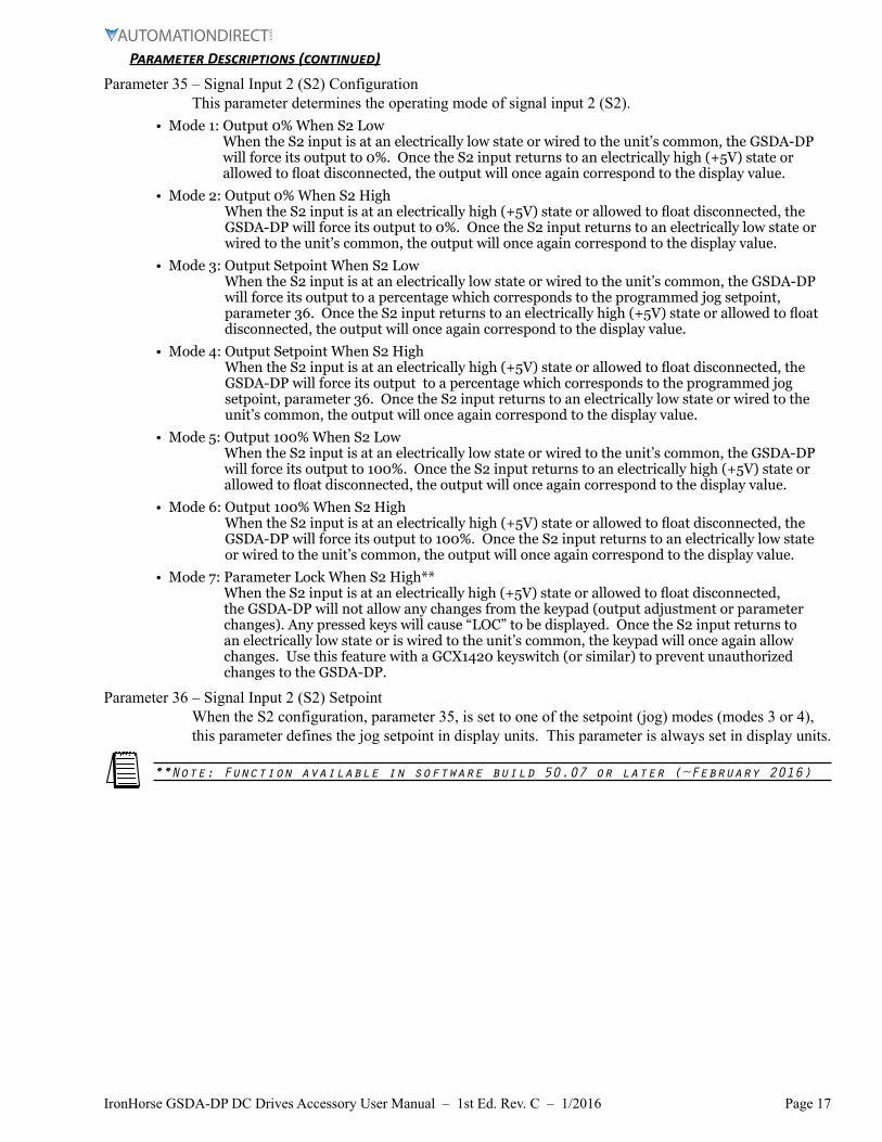
Parameter 35 – Signal Input 2 (S2) Configuration This parameter determines the operating mode of signal input 2 (S2).
• Mode 1: Output 0% When S2 Low When the S2 input is at an electrically low state or wired to the unit’s common, the GSDA-DP will force its output to 0%. Once the S2 input returns to an electrically high (+5V) state or allowed to float disconnected, the output will once again correspond to the display value.
• Mode 2: Output 0% When S2 High When the S2 input is at an electrically high (+5V) state or allowed to float disconnected, the GSDA-DP will force its output to 0%. Once the S2 input returns to an electrically low state or wired to the unit’s common, the output will once again correspond to the display value.
• Mode 3: Output Setpoint When S2 Low When the S2 input is at an electrically low state or wired to the unit’s common, the GSDA-DP will force its output to a percentage which corresponds to the programmed jog setpoint, parameter 36. Once the S2 input returns to an electrically high (+5V) state or allowed to float disconnected, the output will once again correspond to the display value.
• Mode 4: Output Setpoint When S2 High When the S2 input is at an electrically high (+5V) state or allowed to float disconnected, the GSDA-DP will force its output to a percentage which corresponds to the programmed jog setpoint, parameter 36. Once the S2 input returns to an electrically low state or wired to the unit’s common, the output will once again correspond to the display value.
• Mode 5: Output 100% When S2 Low When the S2 input is at an electrically low state or wired to the unit’s common, the GSDA-DP will force its output to 100%. Once the S2 input returns to an electrically high (+5V) state or allowed to float disconnected, the output will once again correspond to the display value.
• Mode 6: Output 100% When S2 High When the S2 input is at an electrically high (+5V) state or allowed to float disconnected, the GSDA-DP will force its output to 100%. Once the S2 input returns to an electrically low state or wired to the unit’s common, the output will once again correspond to the display value.
• Mode 7: Parameter Lock When S2 High** When the S2 input is at an electrically high (+5V) state or allowed to float disconnected, the GSDA-DP will not allow any changes from the keypad (output adjustment or parameter changes). Any pressed keys will cause “LOC” to be displayed. Once the S2 input returns to an electrically low state or is wired to the unit’s common, the keypad will once again allow changes. Use this feature with a GCX1420 keyswitch (or similar) to prevent unauthorized changes to the GSDA-DP.
Parameter 36 – Signal Input 2 (S2) Setpoint When the S2 configuration, parameter 35, is set to one of the setpoint (jog) modes (modes 3 or 4), this parameter defines the jog setpoint in display units. This parameter is always set in display units.
**Note: Function available in software build 50.07 or later (~February 2016)
Page 18 IronHorse GSDA-DP DC Drives Accessory User Manual – 1st Ed. Rev. C – 1/2016
Parameter Descriptions (continued)
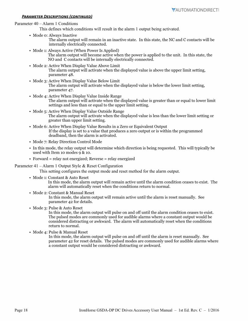
Parameter 40 – Alarm 1 Conditions This defines which conditions will result in the alarm 1 output being activated.
• Mode 0: Always Inactive The alarm output will remain in an inactive state. In this state, the NC and C contacts will be internally electrically connected.
• Mode 1: Always Active (When Power Is Applied) The alarm output will become active when the power is applied to the unit. In this state, the NO and C contacts will be internally electrically connected.
• Mode 2: Active When Display Value Above Limit The alarm output will activate when the displayed value is above the upper limit setting, parameter 48.
• Mode 3: Active When Display Value Below Limit The alarm output will activate when the displayed value is below the lower limit setting, parameter 47.
• Mode 4: Active When Display Value Inside Range The alarm output will activate when the displayed value is greater than or equal to lower limit settings and less than or equal to the upper limit setting.
• Mode 5: Active When Display Value Outside Range The alarm output will activate when the displayed value is less than the lower limit setting or greater than upper limit setting.
• Mode 6: Active When Display Value Results in a Zero or Equivalent Output If the display is set to a value that produces a zero output or is within the programmed deadband, then the alarm is activated.
• Mode 7: Relay Direction Control Mode
• In this mode, the relay output will determine which direction is being requested. This will typically be used with Item 10 modes 9 & 10.
• Forward = relay not energized; Reverse = relay energized
Parameter 41 – Alarm 1 Output Style & Reset Configuration This setting configures the output mode and reset method for the alarm output.
• Mode 1: Constant & Auto Reset In this mode, the alarm output will remain active until the alarm condition ceases to exist. The alarm will automatically reset when the conditions return to normal.
• Mode 2: Constant & Manual Reset In this mode, the alarm output will remain active until the alarm is reset manually. See parameter 42 for details.
• Mode 3: Pulse & Auto Reset In this mode, the alarm output will pulse on and off until the alarm condition ceases to exist. The pulsed modes are commonly used for audible alarms where a constant output would be considered distracting or awkward. The alarm will automatically reset when the conditions return to normal.
• Mode 4: Pulse & Manual Reset In this mode, the alarm output will pulse on and off until the alarm is reset manually. See parameter 42 for reset details. The pulsed modes are commonly used for audible alarms where a constant output would be considered distracting or awkward.
Page 19IronHorse GSDA-DP DC Drives Accessory User Manual – 1st Ed. Rev. C – 1/2016
Parameter Descriptions (continued)
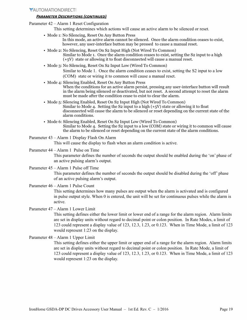
Parameter 42 – Alarm 1 Reset Configuration This setting determines which actions will cause an active alarm to be silenced or reset.
• Mode 1: No Silencing, Reset On Any Button Press In this mode, an active alarm cannot be silenced. Once the alarm condition ceases to exist, however, any user-interface button may be pressed to cause a manual reset.
• Mode 2: No Silencing, Reset On S2 Input High (Not Wired To Common) Similar to Mode 1. Once the alarm condition ceases to exist, setting the S2 input to a high (+5V) state or allowing it to float disconnected will cause a manual reset.
• Mode 3: No Silencing, Reset On S2 Input Low (Wired To Common) Similar to Mode 1. Once the alarm condition ceases to exist, setting the S2 input to a low (COM) state or wiring it to common will cause a manual reset.
• Mode 4: Silencing Enabled, Reset On Any Button Press When the conditions for an active alarm persist, pressing any user-interface button will result in the alarm being silenced or deactivated, but not reset. A second attempt to reset the alarm must be made after the condition cease to exist to clear the alarm.
• Mode 5: Silencing Enabled, Reset On S2 Input High (Not Wired To Common) Similar to Mode 4. Setting the S2 input to a high (+5V) state or allowing it to float disconnected will cause the alarm to be silenced or reset depending on the current state of the alarm conditions.
• Mode 6: Silencing Enabled, Reset On S2 Input Low (Wired To Common) Similar to Mode 4. Setting the S2 input to a low (COM) state or wiring it to common will cause the alarm to be silenced or reset depending on the current state of the alarm conditions.
Parameter 43 – Alarm 1 Display Flash On Alarm This will cause the display to flash when an alarm condition is active.
Parameter 44 – Alarm 1 Pulse on Time This parameter defines the number of seconds the output should be enabled during the ‘on’ phase of an active pulsing alarm’s output.
Parameter 45 – Alarm 1 Pulse off Time This parameter defines the number of seconds the output should be disabled during the ‘off’ phase of an active pulsing alarm’s output.
Parameter 46 – Alarm 1 Pulse Count This setting determines how many pulses are output when the alarm is activated and is configured in pulse output style. When 0 is entered, the unit will be set for continuous pulses while the alarm is active.
Parameter 47 – Alarm 1 Lower Limit This setting defines either the lower limit or lower end of a range for the alarm region. Alarm limits are set in display units without regard to decimal point or colon position. In Rate Modes, a limit of 123 could represent a display value of 123, 12.3, 1.23, or 0.123. When in Time Mode, a limit of 123 would represent 1:23 on the display.
Parameter 48 – Alarm 1 Upper Limit This setting defines either the upper limit or upper end of a range for the alarm region. Alarm limits are set in display units without regard to decimal point or colon position. In Rate Mode, a limit of 123 could represent a display value of 123, 12.3, 1.23, or 0.123. When in Time Mode, a limit of 123 would represent 1:23 on the display.
Page 20 IronHorse GSDA-DP DC Drives Accessory User Manual – 1st Ed. Rev. C – 1/2016
Parameter Descriptions (continued)
Parameter 95 – Factory Default Command When set to a value of 5, the unit will be reset to factory default settings. This can also be achieved by applying power to the unit with both the Enter and Down buttons depressed. The programming jumper must be in the “On” position for this method to function.
Parameter 98 – Save to User Default Area Command When set to a value of 1, the unit will store all adjustable parameters to the user default area. The user default area is intended to be a location where an OEM or integrator can store settings specific to their application. Using this, an OEM can easily refresh their custom settings in the field if an end-user accidentally reconfigures the unit unsuccessfully. Another common use for this area is testing and initial setup. The user can store known-good settings here and easily experiment without the fear of losing the optimal configuration.
Parameter 99 – Restore from User Default Area Command When set to a value of 1, the unit will restore all adjustable parameters from the user default area. See parameter 98 for additional information.
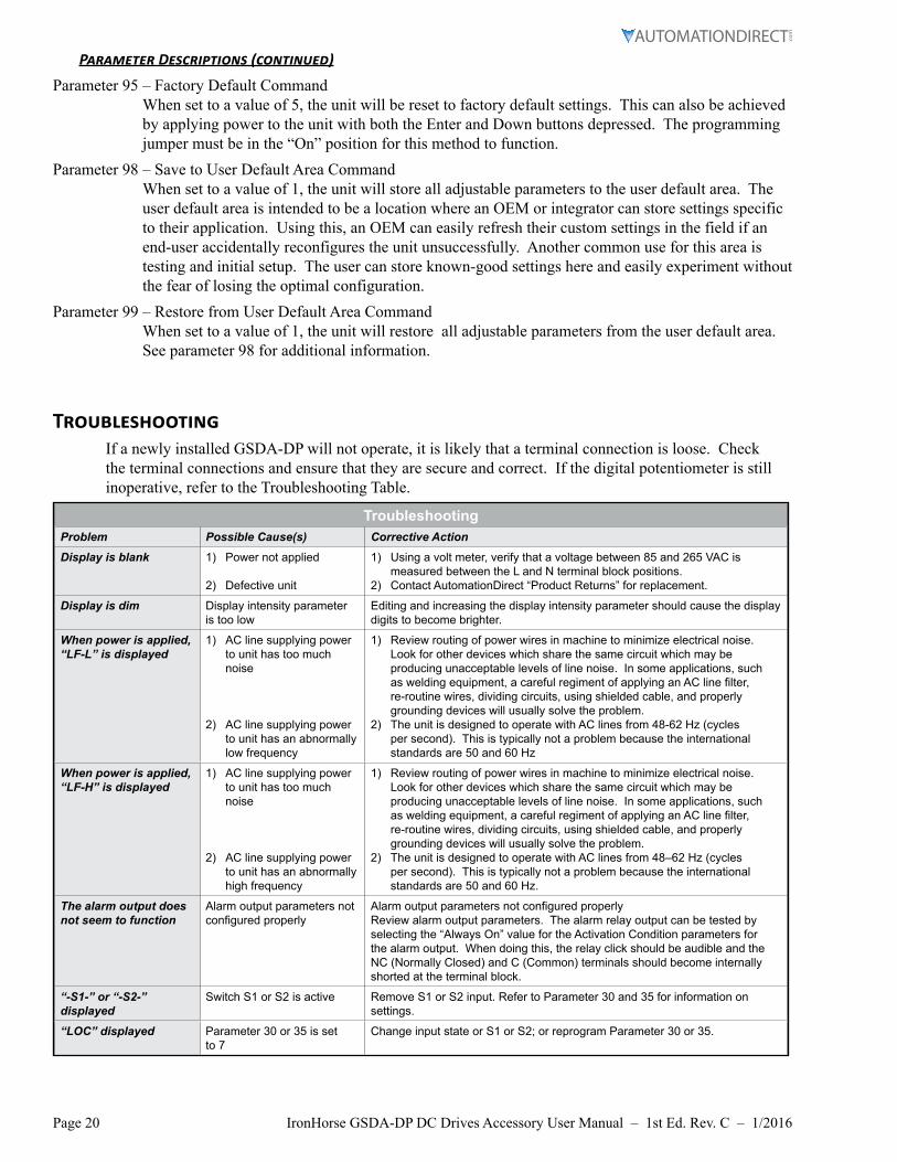
TroubleshootingIf a newly installed GSDA-DP will not operate, it is likely that a terminal connection is loose. Check the terminal connections and ensure that they are secure and correct. If the digital potentiometer is still inoperative, refer to the Troubleshooting Table.
TroubleshootingProblem Possible Cause(s) Corrective Action
Display is blank 1) Power not applied
2) Defective unit
1) Using a volt meter, verify that a voltage between 85 and 265 VAC is measured between the L and N terminal block positions.
2) Contact AutomationDirect “Product Returns” for replacement.
Display is dim Display intensity parameter is too low
Editing and increasing the display intensity parameter should cause the display digits to become brighter.
When power is applied, “LF-L” is displayed
1) AC line supplying power to unit has too much noise
2) AC line supplying power to unit has an abnormally low frequency
1) Review routing of power wires in machine to minimize electrical noise. Look for other devices which share the same circuit which may be producing unacceptable levels of line noise. In some applications, such as welding equipment, a careful regiment of applying an AC line filter, re-routine wires, dividing circuits, using shielded cable, and properly grounding devices will usually solve the problem.
2) The unit is designed to operate with AC lines from 48-62 Hz (cycles per second). This is typically not a problem because the international standards are 50 and 60 Hz
When power is applied, “LF-H” is displayed
1) AC line supplying power to unit has too much noise
2) AC line supplying power to unit has an abnormally high frequency
1) Review routing of power wires in machine to minimize electrical noise. Look for other devices which share the same circuit which may be producing unacceptable levels of line noise. In some applications, such as welding equipment, a careful regiment of applying an AC line filter, re-routine wires, dividing circuits, using shielded cable, and properly grounding devices will usually solve the problem.
2) The unit is designed to operate with AC lines from 48–62 Hz (cycles per second). This is typically not a problem because the international standards are 50 and 60 Hz.
The alarm output does not seem to function
Alarm output parameters not configured properly
Alarm output parameters not configured properlyReview alarm output parameters. The alarm relay output can be tested by selecting the “Always On” value for the Activation Condition parameters for the alarm output. When doing this, the relay click should be audible and the NC (Normally Closed) and C (Common) terminals should become internally shorted at the terminal block.
“-S1-” or “-S2-” displayed
Switch S1 or S2 is active Remove S1 or S2 input. Refer to Parameter 30 and 35 for information on settings.
“LOC” displayed Parameter 30 or 35 is set to 7
Change input state or S1 or S2; or reprogram Parameter 30 or 35.

Page 21IronHorse GSDA-DP DC Drives Accessory User Manual – 1st Ed. Rev. C – 1/2016
BLANKPAGE

Page 22 IronHorse GSDA-DP DC Drives Accessory User Manual – 1st Ed. Rev. C – 1/2016
BLANKPAGE

Page 23IronHorse GSDA-DP DC Drives Accessory User Manual – 1st Ed. Rev. C – 1/2016
BLANKPAGE

Page 24 IronHorse GSDA-DP DC Drives Accessory User Manual – 1st Ed. Rev. C – 1/2016
Literature Number: LT148 Drawing Number: A-5-3908C