Embed Size (px)
Citation preview
GSM communicator G16
USER MANUAL
UAB “TRIKDIS” Draugystės str. 17, LT-51229 Kaunas LITHUANIA E-mail: [email protected] Webpage: www.trikdis.lt

©1997-2017 Trikdis 2 www.trikdis.com
GSM communicator G16
Contents
SAFETY REQUIREMENTS......................................................................................................................................... 2
DESCRIPTION ................................................................................................................................................. 3
LIST OF COMPATIBLE CONTROL PANELS ................................................................................................................. 3 TECHNICAL PARAMETERS .................................................................................................................................... 4 COMMUNICATOR BOARD.................................................................................................................................... 4 PURPOSE OF TERMINALS..................................................................................................................................... 4 LIGHT INDICATION ............................................................................................................................................. 5 PACKAGE CONTENTS .......................................................................................................................................... 5 BEFORE YOU BEGIN ............................................................................................................................................ 5
CONNECT G16 TO TRIKDISCONFIG ................................................................................................................. 5
STATUS BAR DESCRIPTION ................................................................................................................................... 7
SET OPERATION PARAMETERS ...................................................................................................................... 7
SYSTEM SETTINGS WINDOW ................................................................................................................................ 7 ARC REPORTING WINDOW→ ARC REPORTING TAB ................................................................................................. 8 ARC REPORTING WINDOW→ SETTINGS TAB ........................................................................................................... 9 USER REPORTING WINDOW → PROTEGUS SERVICE TAB ............................................................................................ 9 USER REPORTING WINDOW → SMS & CALL REPORTING TAB .................................................................................. 10 USER REPORTING WINDOW → REMOTE CONTROL TAB ........................................................................................... 10 3.6.1 SMS Commands list ................................................................................................................................................ 11 SIM CARD WINDOW ........................................................................................................................................ 11 EVENT SUMMARY WINDOW ............................................................................................................................... 12
PHYSICAL INSTALLATION PROCESS .............................................................................................................. 13
ADD COMMUNICATOR IN PROTEGUS .......................................................................................................... 15
MANUAL FIRMWARE UPDATE ..................................................................................................................... 16
Safety Requirements
The security alarm system should be installed and maintained by qualified personnel.
Prior to installation, please read carefully this manual in order to avoid mistakes that can lead to malfunction or even damage to the equipment.
Disconnect power supply before making any electrical connections.
Changes, modifications or repairs not authorized by the manufacturer shall void your rights under the warranty.
Please act according to your local rules and do not dispose of your unusable alarm system or its components with other household waste.
©1997-2017 Trikdis 3 www.trikdis.com
GSM communicator G16
Description
Communicator G16 is intended to upgrade compatible intruder alarm panels for event signalling via cellular network. Communicator transmits full event information to Alarm Receiving Centre. Customers are informed about security system events in Protegus apps or with SMS messages. They can Arm/Disarm the alarm system remotely (via panel’s keyswitch zone or directly via Serial for Paradox panels).
Features
List of Compatible Control Panels*
*Compatible control panels list can be different, depending on which communicator firmware version is used.
Manufacturer Model
DSC® PC1404, PC1565, PC5020, PC1616, PC1832, PC1864
PARADOX®
SPECTRA SP4000, SP5500, SP6000, SP7000
MAGELLAN MG5000, MG5050
DIGIPLEX EVO192
UTC Interlogix® NetworX (Caddx) NX-4v2, NX-6v2, NX-8v2, NX-8e
Texecom® Premier 412, 816, 816+, 832 Premier Elite 12, 24, 48, 88, 168, 640
Connection Connection to control panels via:
o Key bus direct connection; or o Serial port connection
Communications Communication modes:
o GPRS (by request 3G) o SMS
Two main communication channels working simultaneously
Each channel has a separate back-up channel
Connection control with ARC
Simultaneous event reporting to Protegus Mobile/Web application, allowing user to remotely monitor and control its alarm system
Event messages are transmitted in Contact ID codes
Event reporting via SMS messages to four different users in user customized SMS messages
Direct control feature with Paradox.
Inputs and outputs 2 Outputs controlled via:
o Mobile/Web application or o SMS
1 Input, type: NC, NO
Configuration Quick and easy configuration and firmware updates
Access to the device configuration is secured with two level password
©1997-2017 Trikdis 4 www.trikdis.com
GSM communicator G16
Technical Parameters
Parameter Description
GSM modem frequencies 850 / 900 / 1800 / 1900 MHz
3G modem frequencies 800 / 850 / 900 / 1900 / 2100 MHz
Power supply DC 10-18V
Current consumption 60-100 mA (on standby) Up to 250 mA (while sending data)
Transmission protocols TRK, DC-09_2007, DC-09_2012
Message encryption AES 128
Memory Up to 60 messages
Inputs 1, NC/NO type
Output 2 x OC type, commutating up to 0,15 A DC, 30 V max
Parameter configuration Locally via USB port or remotely
Operating environment Temperature from -10 °C to 50 °C, relative humidity – up to 80% at +20 °C
Communicator dimensions 65 x 77 x 25 mm
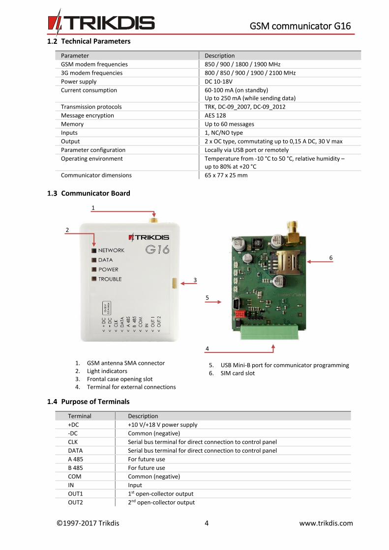
Communicator Board
Purpose of Terminals
Terminal Description
+DC +10 V/+18 V power supply
-DC Common (negative)
CLK Serial bus terminal for direct connection to control panel
DATA Serial bus terminal for direct connection to control panel
A 485 For future use
B 485 For future use
COM Common (negative)
IN Input
OUT1 1st open-collector output
OUT2 2nd open-collector output
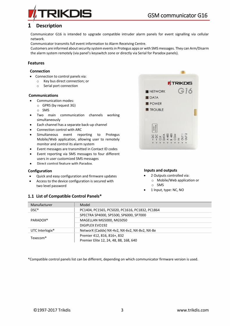
1. GSM antenna SMA connector 2. Light indicators 3. Frontal case opening slot 4. Terminal for external connections
5. USB Mini-B port for communicator programming 6. SIM card slot
5
6
1
2
3
5
4
6
©1997-2017 Trikdis 5 www.trikdis.com
GSM communicator G16
Light Indication
Indicator Light Status Description
Network Off No connection to GSM network
Yellow blinking
Connecting to GSM network
Green solid with yellow blinking
Communicator is connected to GSM network. Sufficient GSM signal strength is level 5 (five yellow flashes)
Data Off No messages in buffer
Green solid Unsent messages in communicator`s memory
Green blinking
(Configuration mode) Data is transferred to/from communicator
Power Off No power supply
Green solid Power supply is sufficient and microcontroller is functioning
Yellow solid Power supply is insufficient (≤11.5V), microcontroller is functioning
Green solid and yellow blinking
(Configuration mode) Communicator is ready for configuration
Yellow solid (Configuration mode) No connection with computer
Trouble OFF No operation problems
1 red blink No SIM card
2 red blinks SIM card PIN code problem (incorrect PIN code)
3 red blinks Programming problem (No APN)
4 red blinks Registration to GSM network problem
5 red blinks Registration to GPRS/UMTS network problem
6 red blinks No connection with the receiver
7 red blinks Lost connection with control panel
Red blinking (Configuration mode) Memory fault
Red solid (Configuration mode) Firmware is corrupted
Package Contents
G16 2G/3G Communicator 1 pc.
GSM antenna ANT01S 1 pc.
Before you begin
Before you begin, make sure that you have the necessary:
1) USB cable (Mini-B type) for configuration. 2) At least 4 wires cable for connecting communicator to control panel. 3) CRP2 cable for connecting to Paradox panel`s Serial port. 4) Flat-head screwdriver.
Order them separately from your local distributor.
Connect G16 to TrikdisConfig
Communicator can be configured using TrikdisConfig software for MS Window OS via USB cable or remotely.
1) Download TrikdisConfig from www.trikdis.com (in search field type TrikdisConfig), and install it.
2) Connect the communicator to TrikdisConfig:
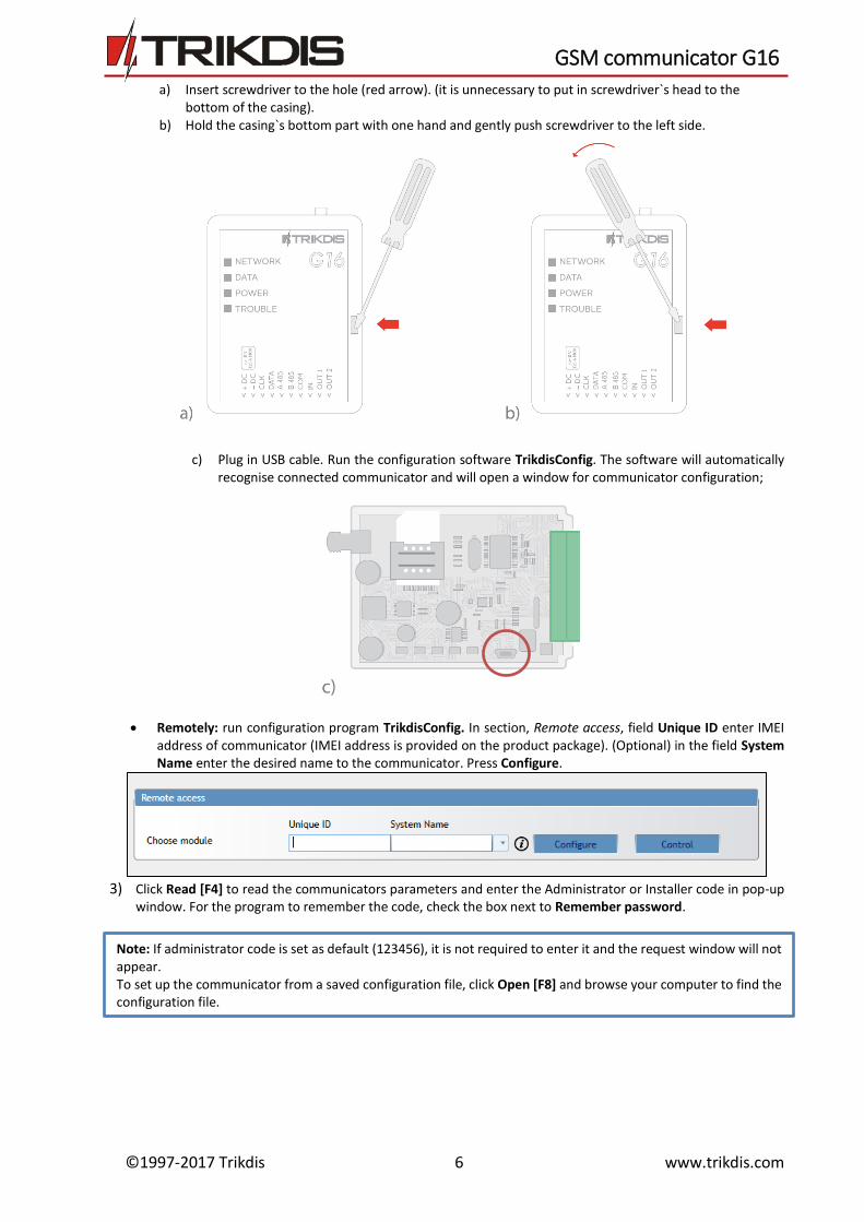
Using USB cable: Carefully open the casing with flat-head screwdriver as shown below:
IMPORTANT: To use remote configuration function, Protegus service must be enabled.
©1997-2017 Trikdis 6 www.trikdis.com
GSM communicator G16
a) Insert screwdriver to the hole (red arrow). (it is unnecessary to put in screwdriver`s head to the bottom of the casing).
b) Hold the casing`s bottom part with one hand and gently push screwdriver to the left side.
c) Plug in USB cable. Run the configuration software TrikdisConfig. The software will automatically
recognise connected communicator and will open a window for communicator configuration;
Remotely: run configuration program TrikdisConfig. In section, Remote access, field Unique ID enter IMEI address of communicator (IMEI address is provided on the product package). (Optional) in the field System Name enter the desired name to the communicator. Press Configure.
3) Click Read [F4] to read the communicators parameters and enter the Administrator or Installer code in pop-up
window. For the program to remember the code, check the box next to Remember password.
Note: If administrator code is set as default (123456), it is not required to enter it and the request window will not appear. To set up the communicator from a saved configuration file, click Open [F8] and browse your computer to find the configuration file.
©1997-2017 Trikdis 7 www.trikdis.com
GSM communicator G16
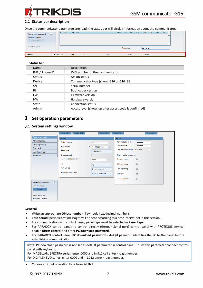
Status bar description
Once the communicator parameters are read, the status bar will display information about the communicator.
Status bar
Name Description
IMEI/Unique ID IMEI number of the communicator
Status Action status
Device Communicator type (shows G16 or G16_3G)
SN Serial number
BL Bootloader version
FW Firmware version
HW Hardware version
State Connection status
Admin Access level (shows up after access code is confirmed)
Set operation parameters
System settings window
General Write an appropriate Object number (4 symbols hexadecimal number).
Test period: periodic test messages will be sent according to a time interval set in this section.
For communication with control panel, panel type must be selected in Panel type.
For PARADOX control panel: to control directly (through Serial port) control panel with PROTEGUS service, enable Direct control and enter PC download password.
For PARADOX control panel: PC download password – 4-digit password identifies the PC to the panel before establishing communication.
Choose an input operation type from list IN1.
Note: PC download password is not set as default parameter in control panel. To set this parameter connect control panel with keyboard, For MAGELLAN, SPECTRA series: enter 0000 and in 911 cell enter 4-digit number. For DIGIPLEX EVO series: enter 0000 and in 3012 enter 4-digit number.
©1997-2017 Trikdis 8 www.trikdis.com
GSM communicator G16
Choose an output operation type from list OUT1-OUT2.
Specify time synchronization (Communicator will use time according to selected server) and output/input parameters.
Access The communicator G16 have two access levels for configuring the communicator:
Administrator code - allows full access to the configuration.
Installer code - allows limited access for installer to the configuration.
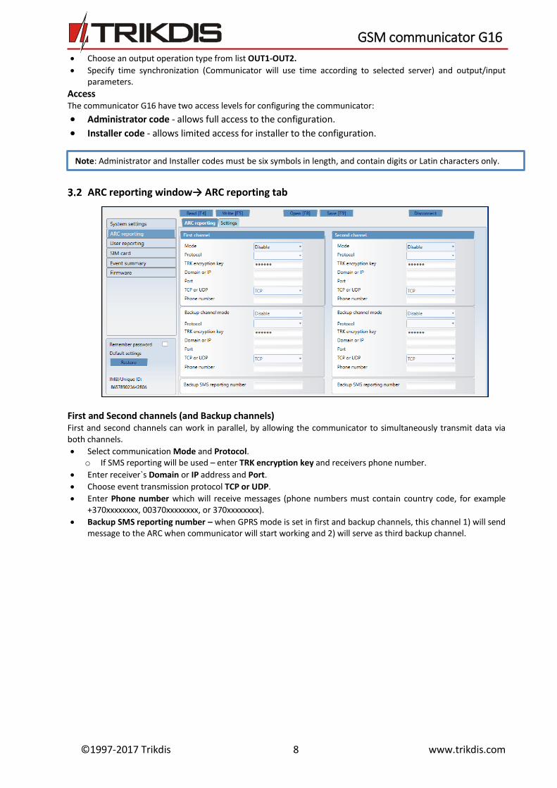
ARC reporting window→ ARC reporting tab
First and Second channels (and Backup channels) First and second channels can work in parallel, by allowing the communicator to simultaneously transmit data via both channels.
Select communication Mode and Protocol. o If SMS reporting will be used – enter TRK encryption key and receivers phone number.
Enter receiver`s Domain or IP address and Port.
Choose event transmission protocol TCP or UDP.
Enter Phone number which will receive messages (phone numbers must contain country code, for example +370xxxxxxxx, 00370xxxxxxxx, or 370xxxxxxxx).
Backup SMS reporting number – when GPRS mode is set in first and backup channels, this channel 1) will send message to the ARC when communicator will start working and 2) will serve as third backup channel.
Note: Administrator and Installer codes must be six symbols in length, and contain digits or Latin characters only.
©1997-2017 Trikdis 9 www.trikdis.com
GSM communicator G16
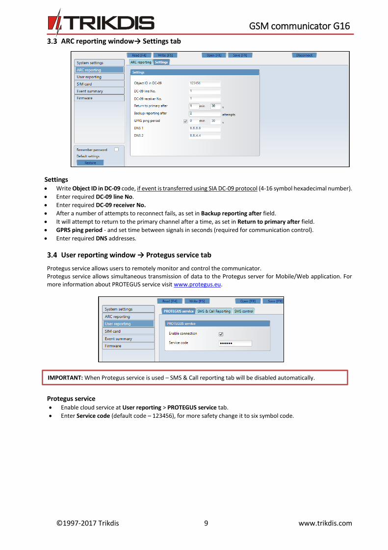
ARC reporting window→ Settings tab
Settings Write Object ID in DC-09 code, if event is transferred using SIA DC-09 protocol (4-16 symbol hexadecimal number).
Enter required DC-09 line No.
Enter required DC-09 receiver No.
After a number of attempts to reconnect fails, as set in Backup reporting after field.
It will attempt to return to the primary channel after a time, as set in Return to primary after field.
GPRS ping period - and set time between signals in seconds (required for communication control).
Enter required DNS addresses.
User reporting window → Protegus service tab
Protegus service allows users to remotely monitor and control the communicator. Protegus service allows simultaneous transmission of data to the Protegus server for Mobile/Web application. For more information about PROTEGUS service visit www.protegus.eu.
Protegus service Enable cloud service at User reporting > PROTEGUS service tab.
Enter Service code (default code – 123456), for more safety change it to six symbol code.
IMPORTANT: When Protegus service is used – SMS & Call reporting tab will be disabled automatically.
©1997-2017 Trikdis 10 www.trikdis.com
GSM communicator G16
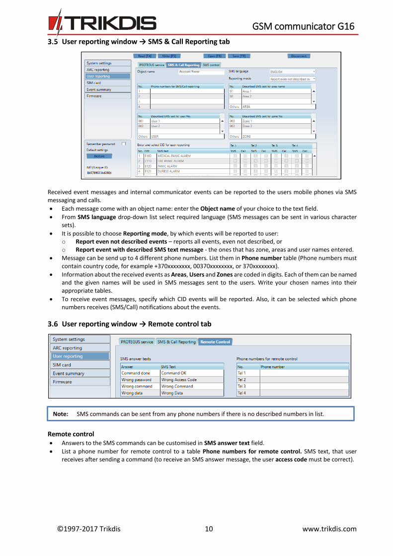
User reporting window → SMS & Call Reporting tab
Received event messages and internal communicator events can be reported to the users mobile phones via SMS messaging and calls.
Each message come with an object name: enter the Object name of your choice to the text field.
From SMS language drop-down list select required language (SMS messages can be sent in various character sets).
It is possible to choose Reporting mode, by which events will be reported to user: o Report even not described events – reports all events, even not described, or o Report event with described SMS text message - the ones that has zone, areas and user names entered.
Message can be send up to 4 different phone numbers. List them in Phone number table (Phone numbers must contain country code, for example +370xxxxxxxx, 00370xxxxxxxx, or 370xxxxxxxx).
Information about the received events as Areas, Users and Zones are coded in digits. Each of them can be named and the given names will be used in SMS messages sent to the users. Write your chosen names into their appropriate tables.
To receive event messages, specify which CID events will be reported. Also, it can be selected which phone numbers receives (SMS/Call) notifications about the events.
User reporting window → Remote control tab
Remote control Answers to the SMS commands can be customised in SMS answer text field.
List a phone number for remote control to a table Phone numbers for remote control. SMS text, that user receives after sending a command (to receive an SMS answer message, the user access code must be correct).
Note: SMS commands can be sent from any phone numbers if there is no described numbers in list.
©1997-2017 Trikdis 11 www.trikdis.com
GSM communicator G16
3.6.1 SMS Commands list
SMS Commands are used to remotely control the communicator. As access code use “Administrator code” or “Installer code”, “_” represents a space. SMS command structure: AccessCode_Command_Data.
Command Data Description
INFO Information about the communicator request. The response will include: communicator type, IMEI number, serial number and firmware version.
RESET Restart the communicator.
OUTPUTx ON Turn on the output, where “x” represents output number 1 or 2.
OFF Turn off the output, where “x” represents output number 1 or 2.
PULSE tttt
Turn on the output for a number of seconds, where “x” represents output number (1) and “tttt” a four-digit number representing pulse duration in seconds.
Examples For the example purposes access code is 123456. To receive information about the communicator:
“123456 INFO” To turn on the output OUT1:
“123456 OUTPUT1 ON” To turn on the output OUT1 for 3 seconds:
“123456 OUTPUT1 PULSE=0003”
SIM card window
Ensure that the SIM card is working, before using it. If GPRS or 3G communication is required, ensure mobile data service is enabled. For information, how to enable this service please contact your GSM service provider.
SIM card Enter SIM card PIN, APN.
If it is required enter GSM network name and password in fields Login, Password.
Forbid connection when roaming detected (use it when security system is installed near country border, this will ensure that communicator would not connect wrong GSM network).
©1997-2017 Trikdis 12 www.trikdis.com
GSM communicator G16
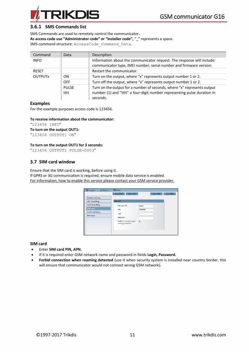
Event summary window
The communicator can generate periodical test messages. To enable globally periodical test messages and set the period time, navigate to System settings → General → Test period. Time is set in day(s) and hours (Maximum 7 days).
Local changes of periodical test messages can be done in Event summary window:
Test and other internal events can be enabled/disabled and their Contact-ID number can be customised. To enable the events generation and set Contact-ID number, navigate to Event Summary table.
3.8 To write new parameters to the communicator, click Write [F5].
3.9 Disconnect communicator: Click Disconnect to disconnect from roles (installer or admin) while communicator is connected via USB cable to
computer.
If a configuration is done via USB cable, unplug the USB cable, click Disconnect to go back to first window.
Note: To restore default settings of the communicator, press the Restore button under the Default settings in the bottom left corner of the configuration window. To create a configuration file which contains current parameters, click Save [F9].
©1997-2017 Trikdis 13 www.trikdis.com
GSM communicator G16
Physical installation process
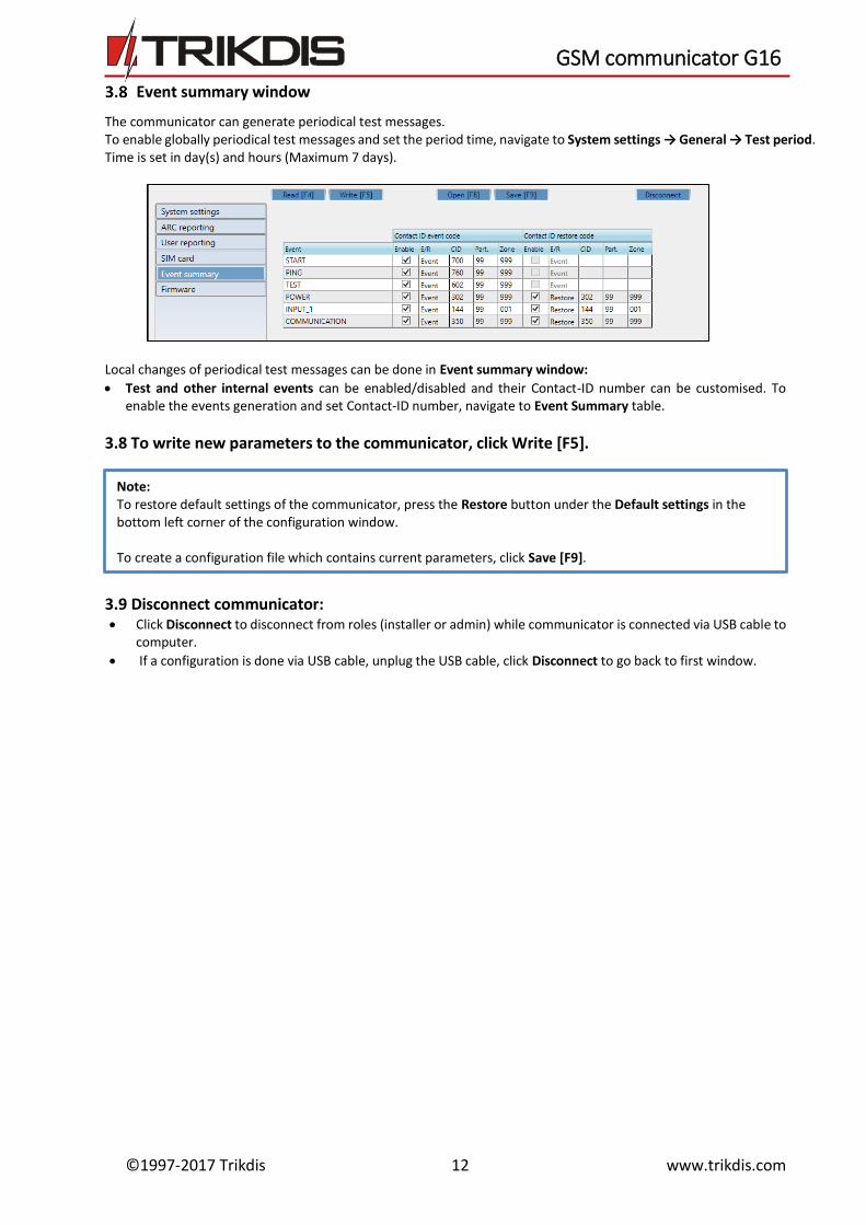
4.1 Insert SIM card into the holder
a) SIM card must be already registered to the GSM network, if GPRS communication will be used, ensure to enable mobile data service.
b) To configure the communicator remotely, insert a SIM card with the PIN code request function disabled.
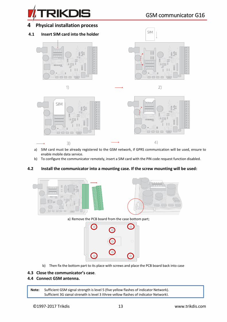
4.2 Install the communicator into a mounting case. If the screw mounting will be used:
4.3 Close the communicator’s case. 4.4 Connect GSM antenna.
Note: Sufficient GSM signal strength is level 5 (five yellow flashes of indicator Network). Sufficient 3G signal strength is level 3 (three yellow flashes of indicator Network).
b) Then fix the bottom part to its place with screws and place the PCB board back into case
a) Remove the PCB board from the case bottom part;
4)
©1997-2017 Trikdis 14 www.trikdis.com
GSM communicator G16
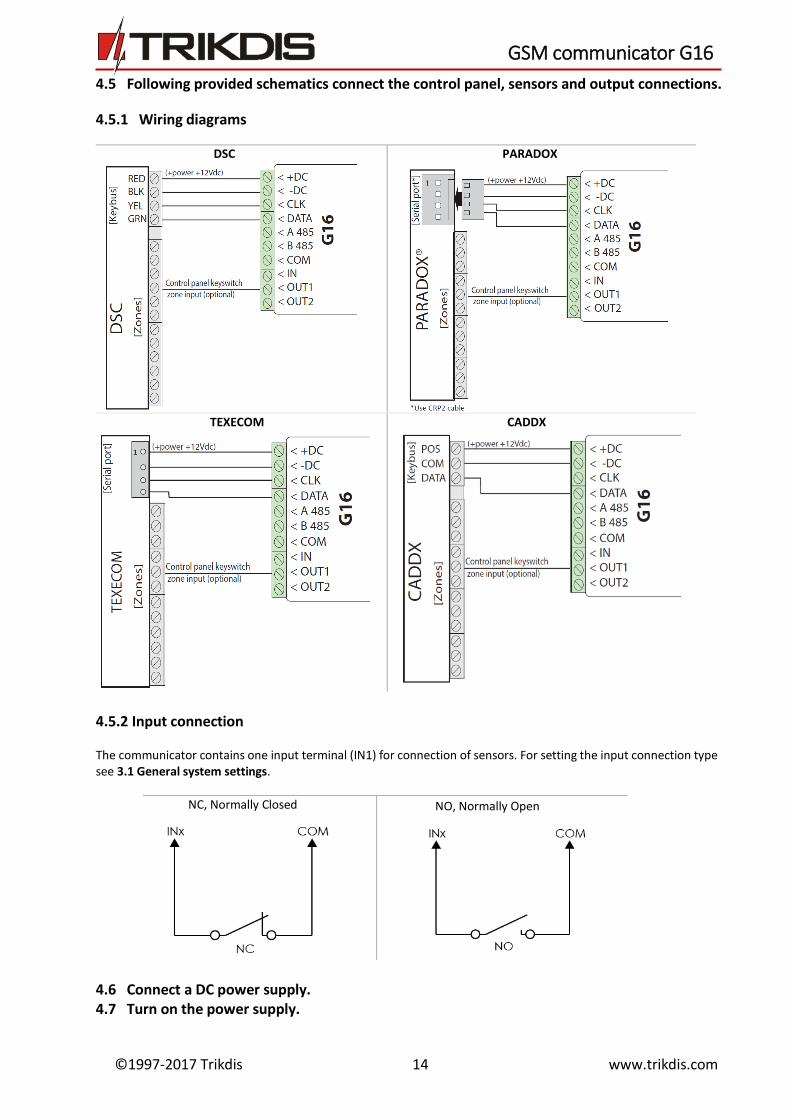
4.5 Following provided schematics connect the control panel, sensors and output connections.
4.5.1 Wiring diagrams
DSC PARADOX
TEXECOM CADDX
4.5.2 Input connection
The communicator contains one input terminal (IN1) for connection of sensors. For setting the input connection type see 3.1 General system settings.
NC, Normally Closed NO, Normally Open
4.6 Connect a DC power supply. 4.7 Turn on the power supply.
©1997-2017 Trikdis 15 www.trikdis.com
GSM communicator G16
4.8 Test communicator performance
1) After configuration and installation is complete, perform a system test. Activate an event in the control panel, and make sure that the event arrives to the alarm receiving centre or is received in the mobile application.
2) To test communicator input, activate it and make sure that the correct messages arrives to recipients. 3) To test the communicator outputs, please activate them remotely. 4) Carry out alarm signalling tests to make sure that the alarm receiving centre receives the signals correctly.
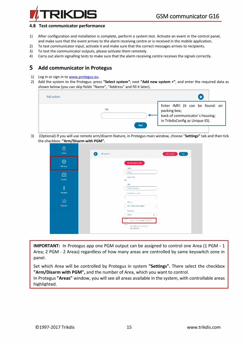
Add communicator in Protegus
1) Log in or sign in to www.protegus.eu. 2) Add the system to the Protegus: press “Select system”; next “Add new system +”, and enter the required data as
shown below (you can skip fields “Name”, “Address” and fill it later).
3) (Optional) If you will use remote arm/disarm feature, in Protegus main window, choose “Settings” tab and then tick
the checkbox: “Arm/Disarm with PGM”.
Enter IMEI (it can be found: on packing box; back of communicator`s housing; in TrikdisConfig as Unique ID).
IMPORTANT: In Protegus app one PGM output can be assigned to control one Area (1 PGM - 1 Area; 2 PGM - 2 Areas) regardless of how many areas are controlled by same keyswitch zone in panel.
Set which Area will be controlled by Protegus in system "Settings". There select the checkbox "Arm/Disarm with PGM", and the number of Area, which you want to control. In Protegus "Areas" window, you will see all areas available in the system, with controllable areas highlighted.
©1997-2017 Trikdis 16 www.trikdis.com
GSM communicator G16
Manual firmware update
The communicator firmware can be updated or changed manually. After an update, all the previous communicator parameters will remain the same. When writing firmware manually, it can be changed to a newer or older version. To update: 1) Run TrikdisConfig. 2) Connect the communicator via USB cable to the computer or connect to the communicator remotely.
If newer firmware version exists, the software will offer to download the newer firmware version file. 3) Select the menu branch Firmware.
4) Press Open firmware and select the required firmware file.
If you do not have the file, the newest firmware file can be downloaded by registered user from www.trikdis.com , under the download section of the G16 communicator.
5) Press Update [F12]. 6) Wait for the prompt of update to complete. 7) Click OK in the prompted window.
Note: If there is an installed antivirus software on your computer, it might block automatic firmware update option. In this case you must reconfigure your antivirus software.