Embed Size (px)
Citation preview
GSM Control Unit
2 G S M C o n t r o l U n i t
Содержание
НАЗНАЧЕНИЕ .............................................................................................................................................. 3
3 G S M C o n t r o l U n i t 3
наЗнаЧение
the GSM control is designed to receive signals, when calling from a mobile phone, as well as • for working out control signals to be used to control the electric operators.the unit, after it has detected a phone call in arrival and indentified the calling number, will • compare this number with its internal list of phone numbers and then, if it matches one of the numbers from the list, it will send an external control signal to the operator. Doing so, the unit will not be answering such calls, the caller thus avoiding any bills to pay.the unit can keep in its memory up to 500 phone numbers.• the unit will cancel the activation signal after the time-out provided or when receiving a signal • from its external push-button or a sensor.to provide more comfort, the unit’s configuration could be set using signals arriving with the • SMS or from a PC via an integrated rS232 serial interface.
Voltage supply 10-15 V
Absorbed power, not exceeding 2 W
Operating temperature -20 +40
Maximum switch-controlled current 5 А
Maximum switch-controlled voltage 220 V
TechnicAl dATA
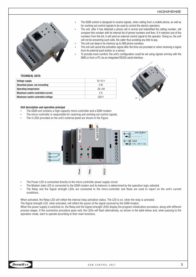
Unit description and operation principalthe GSM unit contains a high-capacity micro-controller and a GSM modem.• the micro-controller is responsible for receiving and working out control signals.• the 4 lEDs provided on the unit’s external panel are shown in the Figure.•
the Power lED is connected directly to the micro-controller power supply circuit.• the Modem state lED is connected to the GSM modem and its behavior is determined by the operation logic selected.• the relay and the Signal strength lEDs are connected to the micro-controller and these are used to report on the unit’s current • conditions.
When activated, the relay lED will reflect the internal relay activation status. the lED is on, when the relay is activated.the Signal strength lED, when activated, will reflect the power of the signal received by the GSM modem.When the power supply is switched on, the relay and the Signal strength lEDS display the program initialization procedure, along with different process stages. if the connection procedure goes well, the lEDs will flash alternatively, as shown in the table below and, when passing to the operation mode, start to operate according to their main functions.
4 G S M C o n t r o l U n i t
OperatiOnprinciple
OperATiOn principle When powered, the unit will proceed with the phone number database integrity and memory chip functionality checkup operations.in case of memory errors detected, the unit will not proceed to its operation mode and the Signal strength lED will produce the 2d pulse-level
based sequences.in case of GSM modem related errors and/or inoperability detected, the unit will not proceed to its operation mode and the Signal strength lED
will produce continuous rapid and short pulses.the phone number database integrity checkup operations performed inside the unit will be based on the cyclic redundancy check (CrC)
procedures. in case of mismatch detected, the unit will rewrite all the set points available, thus restoring the initial default values provided:the signal disable set point will then be set to «disabled, when receiving external signal».the relay disable timeout will be set to 5 sec. this however will not be used. the phone number database will be cleared up.When in operation mode, the unit could be connected to a PC to perform some configuration procedures. Doing so and while transferring the
data from the PC to the unit and then back to the PC, the unit will stop to react to any calls and/or SMS in arrival.
preliMinAry prOcedUresAfter acquiring the unit, this shall be subject of configuration procedures consisting in a phone number database to be memorized, that containing
a set of numbers the unit will respond to, as well as the activation signal parameters to be set for the actuator controlled.note: the PC based configuration procedures can be performed both immediately after acquiring the unit and later on as well, after the unit has
been installed.When the unit is switched on for the first time after it has been acquired, its phone number database is empty. the unit is then to be configured
using a PC based software provided, since the SMS based configuration signals will be accepted only from a number which has already been saved within the database provided.
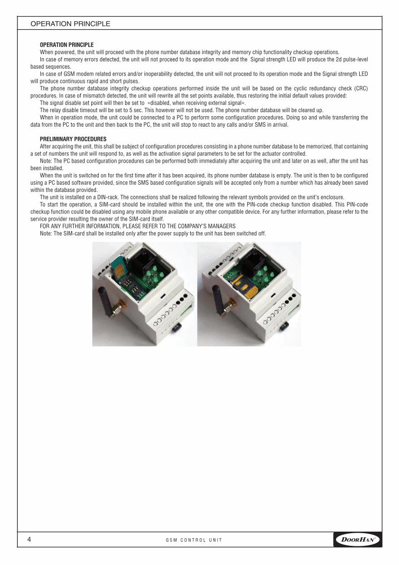
the unit is installed on a Din-rack. the connections shall be realized following the relevant symbols provided on the unit’s enclosure.to start the operation, a SiM-card should be installed within the unit, the one with the Pin-code checkup function disabled. this Pin-code
checkup function could be disabled using any mobile phone available or any other compatible device. For any further information, please refer to the service provider resulting the owner of the SiM-card itself.
For AnY FUrtHEr inForMAtion, PlEASE rEFEr to tHE CoMPAnY’S MAnAGErS note: the SiM-card shall be installed only after the power supply to the unit has been switched off.
5 G S M C o n t r o l U n i t 5
leDstatusesattheunit’sswitch-On
led sTATUses AT The UniT’s swiTch-OnAfter the unit has been connected and configured, it is ready to be used. At its first switch-on, one should make sure the unit has been started
correctly. to do so, the lED statuses shall be observed. When started properly, the lEDs’ activation sequence shall correspond to that shown in the table below.
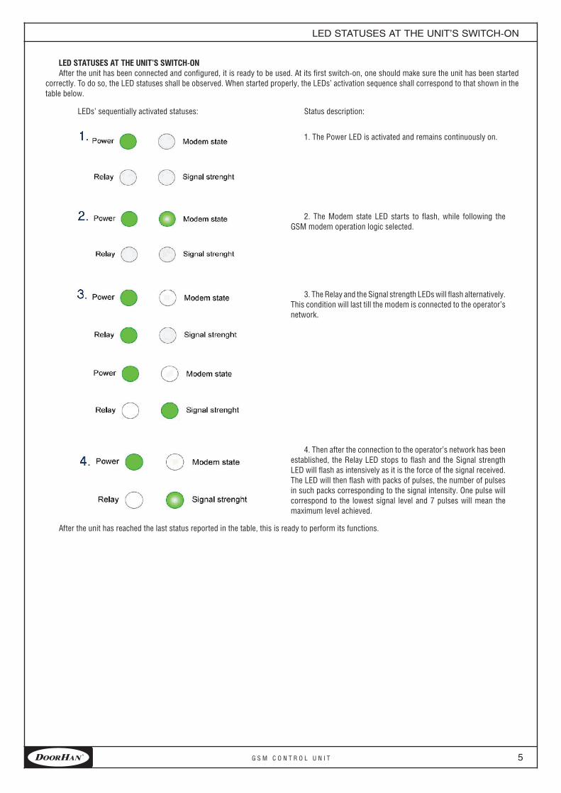
lEDs’ sequentially activated statuses: Status description:
1. the Power lED is activated and remains continuously on.
2. the Modem state lED starts to flash, while following the GSM modem operation logic selected.
3. the relay and the Signal strength lEDs will flash alternatively. this condition will last till the modem is connected to the operator’s network.
4. then after the connection to the operator’s network has been established, the relay lED stops to flash and the Signal strength lED will flash as intensively as it is the force of the signal received. the lED will then flash with packs of pulses, the number of pulses in such packs corresponding to the signal intensity. one pulse will correspond to the lowest signal level and 7 pulses will mean the maximum level achieved.
After the unit has reached the last status reported in the table, this is ready to perform its functions.
6 G S M C o n t r o l U n i t
cOnfiguratiOnsettingusingthesMs’s
cOnfigUrATiOn seTTing Using The sMs’snote: to ensure the SMS based signals are accepted by the unit, the phone number such SMS is sent from shall be part of the unit’s internal
database and saved within the list zero position.
the unit is then capable to receive 3 types of signal messages:1. Saving a number to the phone number database.2. Saving the relay activation signal holding time.3. Saving the external signal receiving mode.
A number saving signal SMS message will be in the form of: P#nnn=xxxxxxx;the «Р» symbol shall be placed in the first position, the “nnn” code shall be replaced by a memory item number, and the ххххххх code will
represent the phone number the unit will respond to.Example: Р#1 =+37069854788; this message indicates the number +37069854788 shall be saved within the position 1.the relay activation signal holding time SMS message will be in the form of: PrtiMt=xxxxx;the «Р» symbol should come first, then the ххххх code will represent the time in ms during which the relay will be hold activated.Example: PrtiMt =5000: this message indicated the relay shall be hold for 5 sec after its activation.
the external signal receiving mode SMS message will be in the form of: PSEn=x;the «Р» symbol should come firs, then the х code could be 0 or 1, where “0” would mean no signal will be received and “1” would mean the
relay could be disabled only after receiving a signal from outside.Example: PSEn =1; this message indicates the relay should be disabled only after the external signal low-signal status has been displayed.
one SMS could contain several control signal messages, with the «;» symbol being used as a divider between the messages.Example: Р#1 =+37069854788;#2=+37069854789;rtiMt=5000;SEn=1;this message indicates the number +37069854788 should be saved within the position 1, the number +37069854789 – within the position 2,
while the relay should be hold activated for 5 sec and disabled only after receiving an external signal.no superfluous symbols or spaces are allowed to be contained in the message.All changes are enabled immediately after the SMS message has been received.
cOnfigUrATiOn seTTing Using A persOnAl cOMpUTerto configure the unit using a PC the following should be done:
Use the remote Switch Configurator software provided.• Connect the GSM unit to the PC using the cable provided. • Start the remote Switch Configurator program and configure the control unit.•
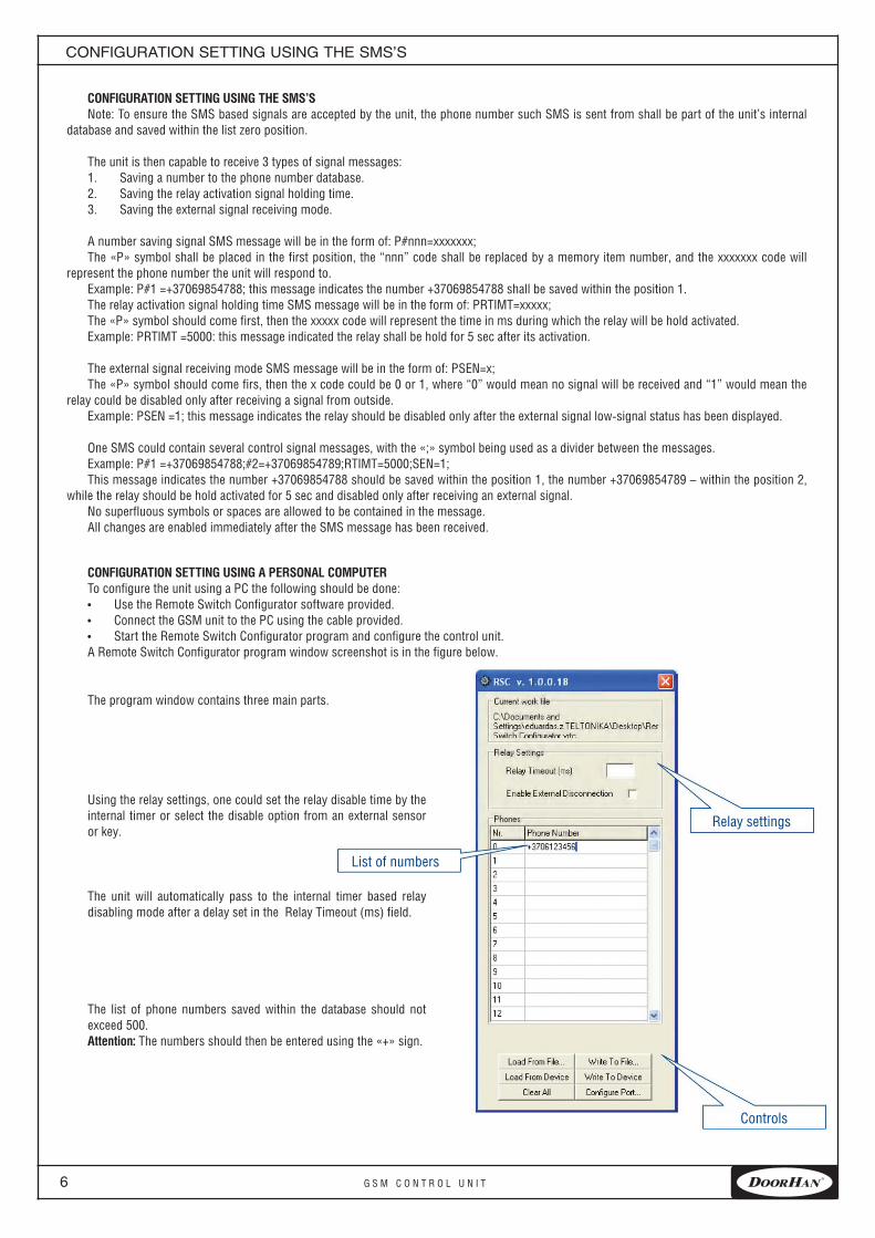
A remote Switch Configurator program window screenshot is in the figure below.
the program window contains three main parts.
Using the relay settings, one could set the relay disable time by the internal timer or select the disable option from an external sensor or key.
the unit will automatically pass to the internal timer based relay disabling mode after a delay set in the relay timeout (ms) field.
the list of phone numbers saved within the database should not exceed 500. Attention: the numbers should then be entered using the «+» sign.
list of numbers
relay settings
Controls
7 G S M C o n t r o l U n i t 7
The cOnTrOl keys prOVided AllOw TO: load the settings from a file - load from file ... Считать • load the settings from a device - load from device • Clear up all fields - Clear all• Save the configuration settings to a file - Write to file... • Save the configuration settings to the unit’s memory - Write to device•
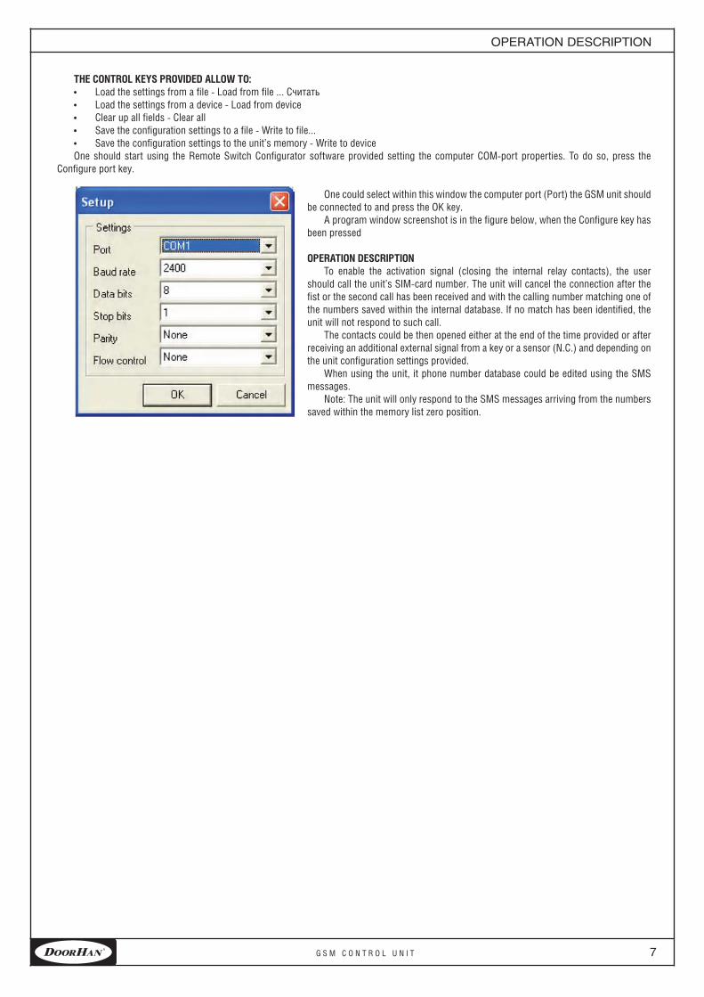
one should start using the remote Switch Configurator software provided setting the computer СОМ-port properties. to do so, press the Configure port key.
one could select within this window the computer port (Port) the GSM unit should be connected to and press the ОК key.
A program window screenshot is in the figure below, when the Configure key has been pressed
OperATiOn descripTiOnto enable the activation signal (closing the internal relay contacts), the user
should call the unit’s SiM-card number. the unit will cancel the connection after the fist or the second call has been received and with the calling number matching one of the numbers saved within the internal database. if no match has been identified, the unit will not respond to such call.
the contacts could be then opened either at the end of the time provided or after receiving an additional external signal from a key or a sensor (n.C.) and depending on the unit configuration settings provided.
When using the unit, it phone number database could be edited using the SMS messages.
note: the unit will only respond to the SMS messages arriving from the numbers saved within the memory list zero position.
OperatiOnDescriptiOn

120 novaya street, Akulovo village, Odintsovo district,Moskow region, 143002 russia
Tel: +7(495)933–2400, 981–1133e–mail: [email protected]
www.doorhan.com