Embed Size (px)
Citation preview

User Manual Revision 1.02
Manufactured by
Contents 1. Introduction .......................................................................................................................................... 4
2. Disclaimer and Warranty ...................................................................................................................... 4
3. Specifications ........................................................................................................................................ 5
4. Features ................................................................................................................................................ 5
5. Quick Start Guide .................................................................................................................................. 6
5.1 Hardware ...................................................................................................................................... 6
5.2 Software ........................................................................................................................................ 7
6. Detailed Operating Instructions .......................................................................................................... 10
6.1 Fetch / Send Settings .................................................................................................................. 10
6.2 Events .......................................................................................................................................... 10
6.2.1 Configuring Events .............................................................................................................. 10
6.2.2 Selecting Events .................................................................................................................. 11
6.3 Board Info ................................................................................................................................... 12
6.4 General Settings .......................................................................................................................... 13
6.4.1 General ................................................................................................................................ 13
6.4.2 Missed Call Control ............................................................................................................. 13
6.4.3 Arm / Disarm Control .......................................................................................................... 13
6.4.4 AC Detect ............................................................................................................................ 14
6.4.5 Daily Test Report ................................................................................................................. 14
6.4.6 Admin Cell Numbers ........................................................................................................... 15
6.4.7 Gate Control Settings .......................................................................................................... 16
6.5 Inputs & Outputs ......................................................................................................................... 17
6.5.1 Digital Inputs ....................................................................................................................... 17
6.5.2 Analog Inputs ...................................................................................................................... 18
6.5.3 Digital Outputs .................................................................................................................... 19
6.6 SMS Messages ............................................................................................................................. 20
6.6.1 Admin SMS Commands ....................................................................................................... 20
6.6.2 Gate Control SMS Commands ............................................................................................. 21
6.7 Logs ............................................................................................................................................. 21
6.8 Manage Settings ......................................................................................................................... 22
6.8.1 Load Default Settings .......................................................................................................... 22
6.8.2 Copy/Paste Settings ............................................................................................................ 22
7. ioXpander Add-On Board .................................................................................................................... 23
7.1 Specifications .............................................................................................................................. 23
7.2 Adding a ioXpander board to your profile .................................................................................. 24
7.3 4-20mA Inputs ............................................................................................................................. 24
1. Introduction
Time is precious, why waste it? The GSM GENIE will save you time and add value to existing customer
infrastructure!
This “jack-off-all-trades” little gem will take care of all the little tasks you do daily. The GSM GENIE will
open your gate, clean your pool, switch your geyser, manage your lights, water your plants, monitor
your alarm, manage your generator or even make a noise itself when you’re not home.
Its uses extends way beyond your home, borehole pump or irrigation, this really is the master of
automation. What about townhouse complex access control or making sure the grandparents are home.
The possibilities are truly endless - the GENIE will simplify your life!
2. Disclaimer and Warranty
Disclaimer: This product is designed to operate as a communication device, which will perform certain
functions if triggered via SMS. It is also able to send an SMS as a result of certain actions. The product
has been manufactured to the best standards and strictly in line with the design specifications, however
the manufacturer, supplier and all other parties cannot guarantee it will function in one hundred
percent of applications and circumstances. The system is reliant on third party service providers and
Sabertek and its partners have no control over these third parties. For this reason we recommend that
you do not use this device for critical services. Although we, and many customers have found it to be
highly successful, please be aware that no party can guarantee its effectiveness. Under no circumstances
should the GSM Genie be used in a medical application, life support or related service.
Warranty: The product is guaranteed against defective workmanship for a period of twelve months
from date of manufacture. As the manufacturer has no control over the use of the product we cannot
guarantee damage caused by poor installation, errors, environmental influences and general misuse or
abuse. If the instructions are followed the GSM Genie should give you many years of trouble free use.
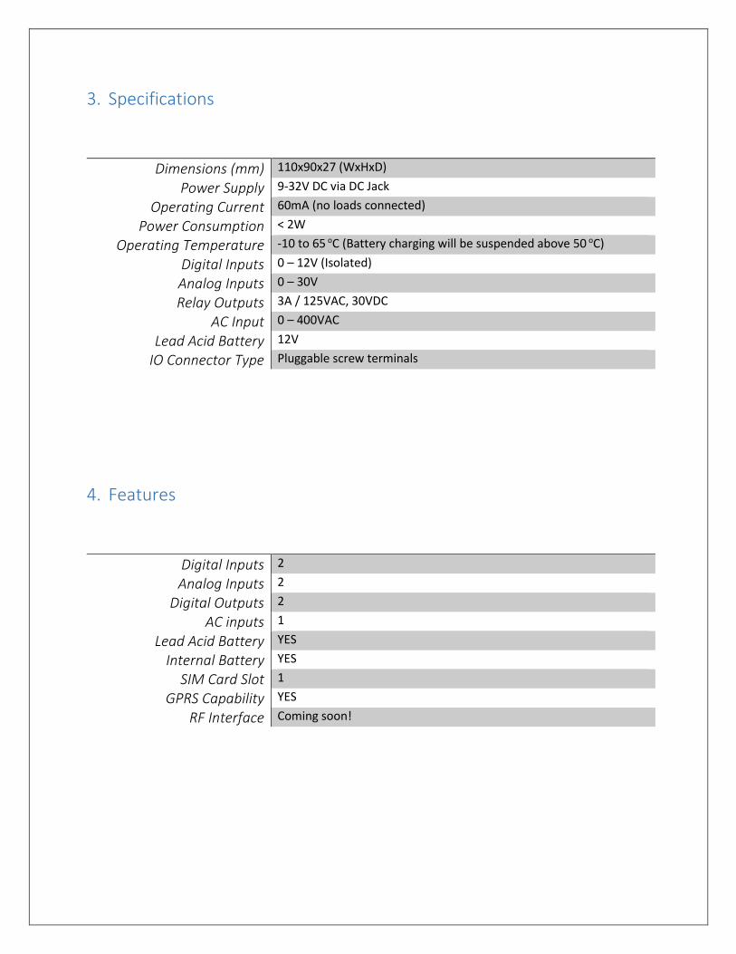
3. Specifications
Specification
Dimensions (mm) 110x90x27 (WxHxD)
Power Supply 9-32V DC via DC Jack
Operating Current 60mA (no loads connected)
Power Consumption < 2W
Operating Temperature -10 to 65 oC (Battery charging will be suspended above 50 oC)
Digital Inputs 0 – 12V (Isolated)
Analog Inputs 0 – 30V
Relay Outputs 3A / 125VAC, 30VDC
AC Input 0 – 400VAC
Lead Acid Battery 12V
IO Connector Type Pluggable screw terminals
4. Features
Digital Inputs 2
Analog Inputs 2
Digital Outputs 2
AC inputs 1
Lead Acid Battery YES
Internal Battery YES
SIM Card Slot 1
GPRS Capability YES
RF Interface Coming soon!
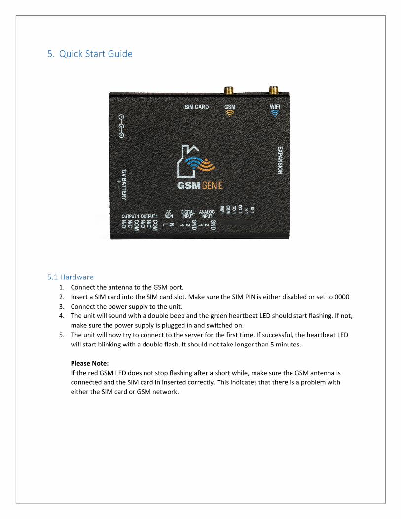
5. Quick Start Guide
5.1 Hardware 1. Connect the antenna to the GSM port.
2. Insert a SIM card into the SIM card slot. Make sure the SIM PIN is either disabled or set to 0000
3. Connect the power supply to the unit.
4. The unit will sound with a double beep and the green heartbeat LED should start flashing. If not,
make sure the power supply is plugged in and switched on.
5. The unit will now try to connect to the server for the first time. If successful, the heartbeat LED
will start blinking with a double flash. It should not take longer than 5 minutes.
Please Note:
If the red GSM LED does not stop flashing after a short while, make sure the GSM antenna is
connected and the SIM card in inserted correctly. This indicates that there is a problem with
either the SIM card or GSM network.
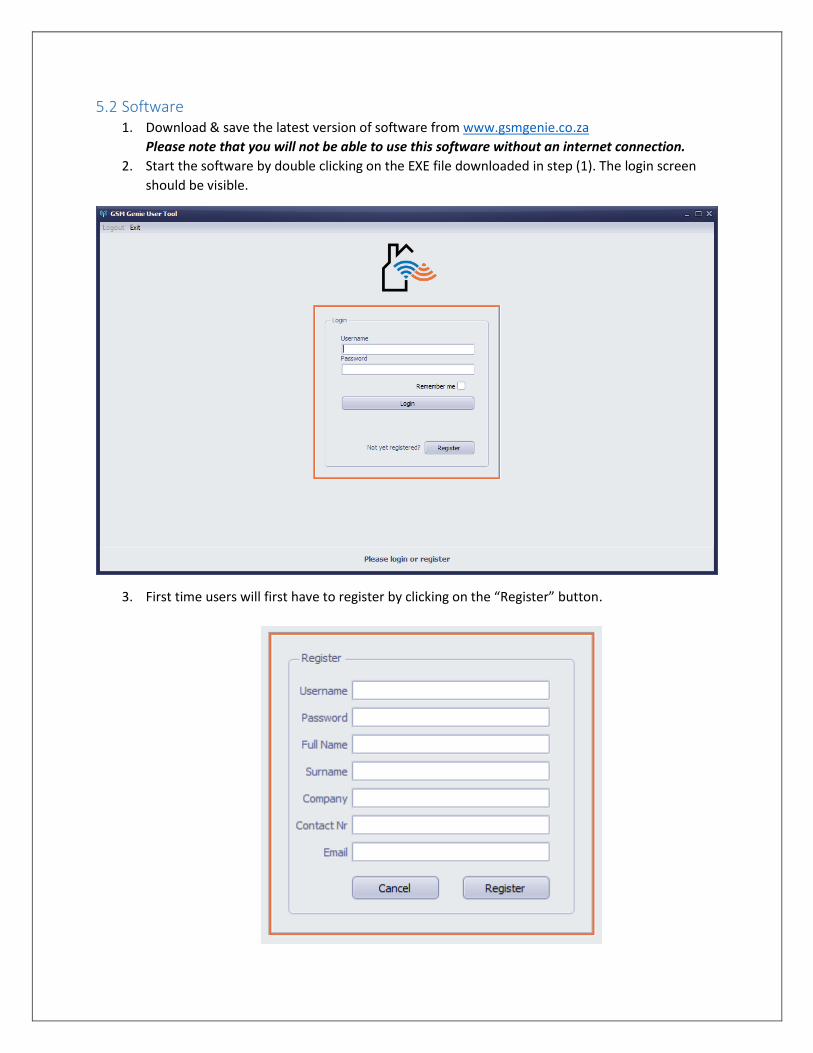
5.2 Software 1. Download & save the latest version of software from www.gsmgenie.co.za
Please note that you will not be able to use this software without an internet connection.
2. Start the software by double clicking on the EXE file downloaded in step (1). The login screen
should be visible.
3. First time users will first have to register by clicking on the “Register” button.
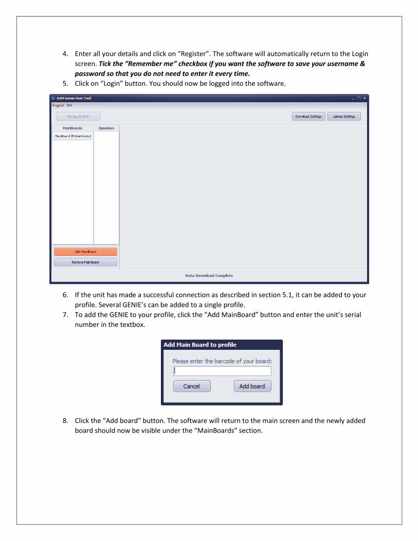
4. Enter all your details and click on “Register”. The software will automatically return to the Login
screen. Tick the “Remember me” checkbox if you want the software to save your username &
password so that you do not need to enter it every time.
5. Click on “Login” button. You should now be logged into the software.
6. If the unit has made a successful connection as described in section 5.1, it can be added to your
profile. Several GENIE’s can be added to a single profile.
7. To add the GENIE to your profile, click the “Add MainBoard” button and enter the unit’s serial
number in the textbox.
8. Click the “Add board” button. The software will return to the main screen and the newly added
board should now be visible under the “MainBoards” section.
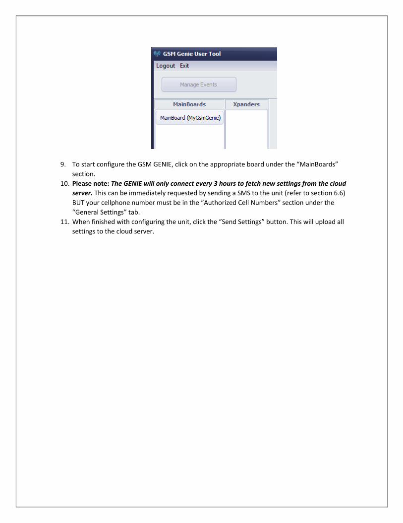
9. To start configure the GSM GENIE, click on the appropriate board under the “MainBoards”
section.
10. Please note: The GENIE will only connect every 3 hours to fetch new settings from the cloud
server. This can be immediately requested by sending a SMS to the unit (refer to section 6.6)
BUT your cellphone number must be in the “Authorized Cell Numbers” section under the
“General Settings” tab.
11. When finished with configuring the unit, click the “Send Settings” button. This will upload all
settings to the cloud server.
6. Detailed Operating Instructions
6.1 Fetch / Send Settings
Fetching / sending of settings to and from the cloud server is done using these buttons. Please note: If
any changes were made, the settings must be uploaded using the “Send Settings” button before it will
take effect.
6.2 Events The GSM GENIE is an event based system where certain inputs can trigger events. Events can be
anything from switching an output or sending a SMS message. The GSM GENIE cater for 64 different
events.
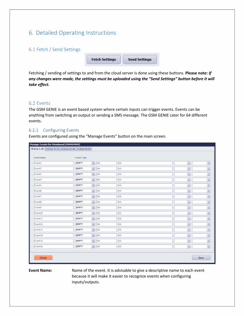
6.2.1 Configuring Events Events are configured using the “Manage Events” button on the main screen.
Event Name: Name of the event. It is advisable to give a descriptive name to each event
because it will make it easier to recognize events when configuring
inputs/outputs.
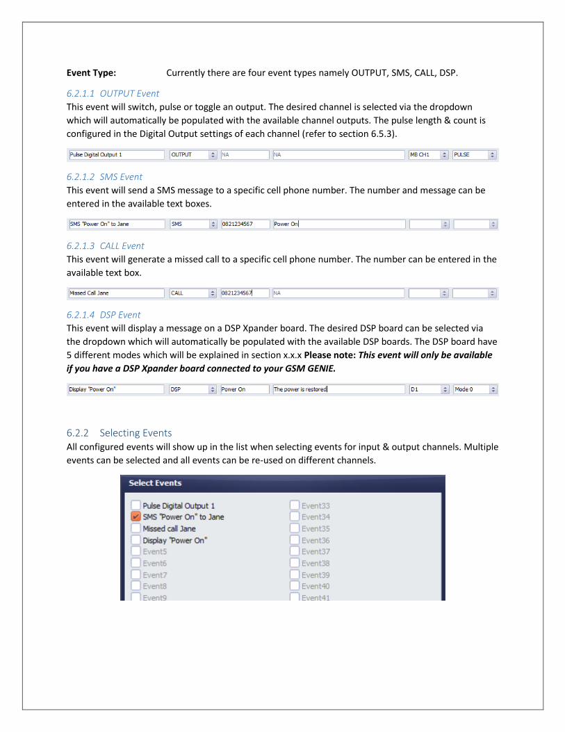
Event Type: Currently there are four event types namely OUTPUT, SMS, CALL, DSP.
6.2.1.1 OUTPUT Event
This event will switch, pulse or toggle an output. The desired channel is selected via the dropdown
which will automatically be populated with the available channel outputs. The pulse length & count is
configured in the Digital Output settings of each channel (refer to section 6.5.3).
6.2.1.2 SMS Event
This event will send a SMS message to a specific cell phone number. The number and message can be
entered in the available text boxes.
6.2.1.3 CALL Event
This event will generate a missed call to a specific cell phone number. The number can be entered in the
available text box.
6.2.1.4 DSP Event
This event will display a message on a DSP Xpander board. The desired DSP board can be selected via
the dropdown which will automatically be populated with the available DSP boards. The DSP board have
5 different modes which will be explained in section x.x.x Please note: This event will only be available
if you have a DSP Xpander board connected to your GSM GENIE.
6.2.2 Selecting Events All configured events will show up in the list when selecting events for input & output channels. Multiple
events can be selected and all events can be re-used on different channels.
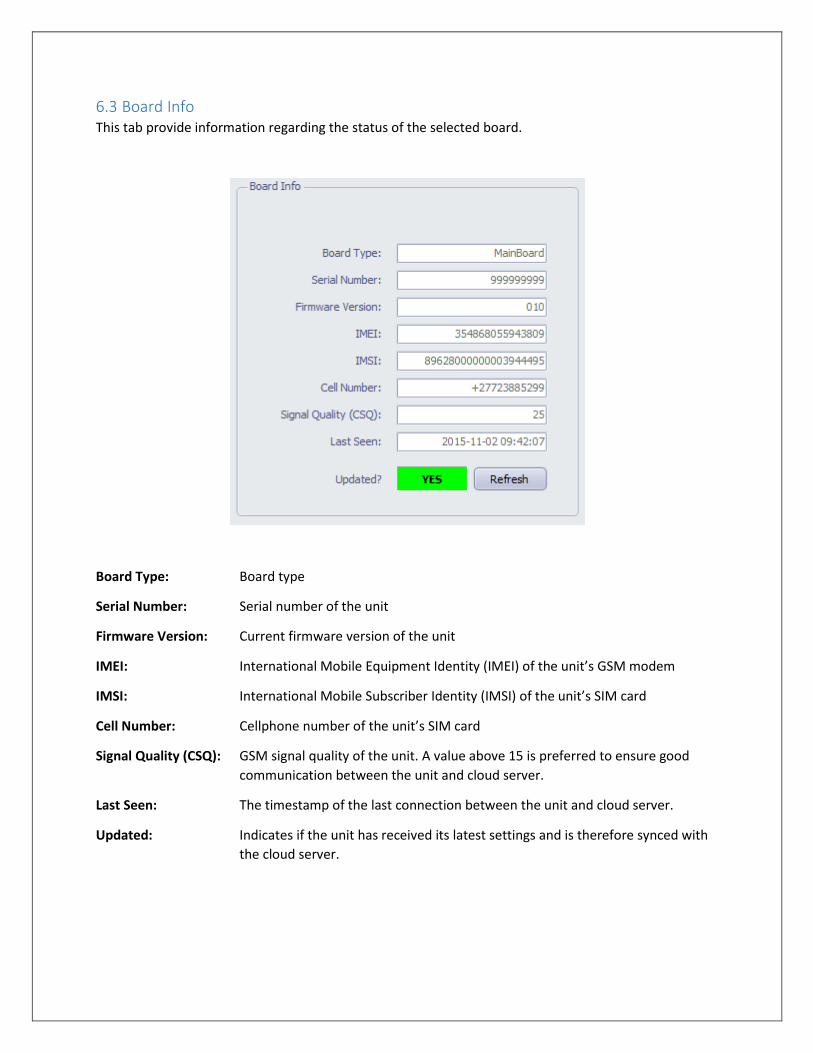
6.3 Board Info This tab provide information regarding the status of the selected board.
Board Type: Board type
Serial Number: Serial number of the unit
Firmware Version: Current firmware version of the unit
IMEI: International Mobile Equipment Identity (IMEI) of the unit’s GSM modem
IMSI: International Mobile Subscriber Identity (IMSI) of the unit’s SIM card
Cell Number: Cellphone number of the unit’s SIM card
Signal Quality (CSQ): GSM signal quality of the unit. A value above 15 is preferred to ensure good
communication between the unit and cloud server.
Last Seen: The timestamp of the last connection between the unit and cloud server.
Updated: Indicates if the unit has received its latest settings and is therefore synced with
the cloud server.
6.4 General Settings
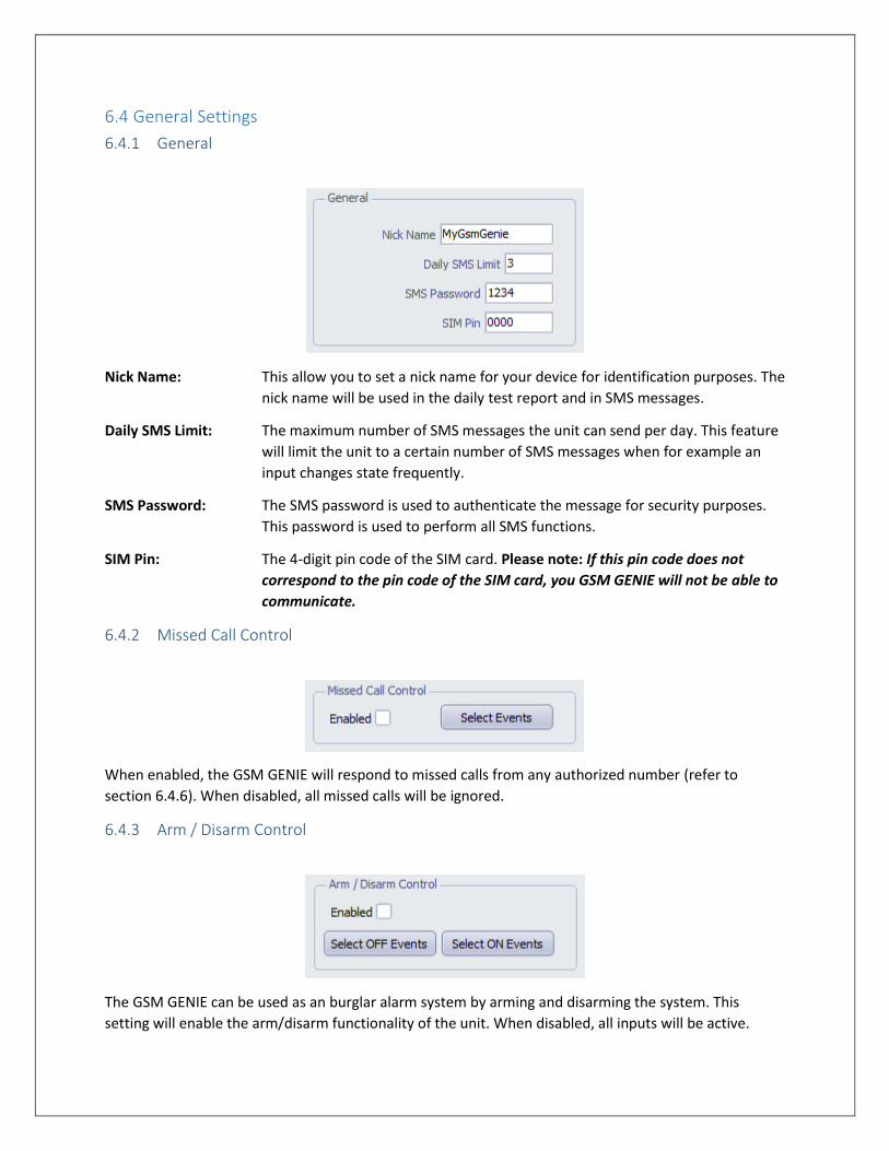
6.4.1 General
Nick Name: This allow you to set a nick name for your device for identification purposes. The
nick name will be used in the daily test report and in SMS messages.
Daily SMS Limit: The maximum number of SMS messages the unit can send per day. This feature
will limit the unit to a certain number of SMS messages when for example an
input changes state frequently.
SMS Password: The SMS password is used to authenticate the message for security purposes.
This password is used to perform all SMS functions.
SIM Pin: The 4-digit pin code of the SIM card. Please note: If this pin code does not
correspond to the pin code of the SIM card, you GSM GENIE will not be able to
communicate.
6.4.2 Missed Call Control
When enabled, the GSM GENIE will respond to missed calls from any authorized number (refer to
section 6.4.6). When disabled, all missed calls will be ignored.
6.4.3 Arm / Disarm Control
The GSM GENIE can be used as an burglar alarm system by arming and disarming the system. This
setting will enable the arm/disarm functionality of the unit. When disabled, all inputs will be active.
When enabled and the system is disarmed, all inputs will be ignored. This is useful when there is for
instance a PIR motion sensor connected to one of the inputs and you only want it to be active at certain
times. When enabled and the system is armed, all inputs will be active. Arming and disarming is done via
a SMS command (refer to section 6.4.3)
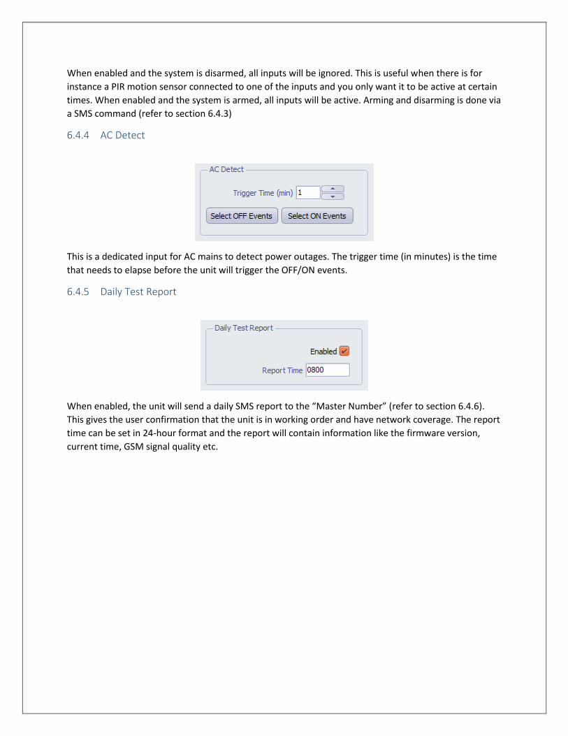
6.4.4 AC Detect
This is a dedicated input for AC mains to detect power outages. The trigger time (in minutes) is the time
that needs to elapse before the unit will trigger the OFF/ON events.
6.4.5 Daily Test Report
When enabled, the unit will send a daily SMS report to the “Master Number” (refer to section 6.4.6).
This gives the user confirmation that the unit is in working order and have network coverage. The report
time can be set in 24-hour format and the report will contain information like the firmware version,
current time, GSM signal quality etc.
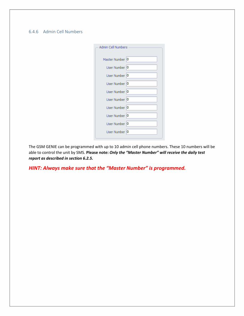
6.4.6 Admin Cell Numbers
The GSM GENIE can be programmed with up to 10 admin cell phone numbers. These 10 numbers will be
able to control the unit by SMS. Please note: Only the “Master Number” will receive the daily test
report as described in section 6.2.5.
HINT: Always make sure that the “Master Number” is programmed.
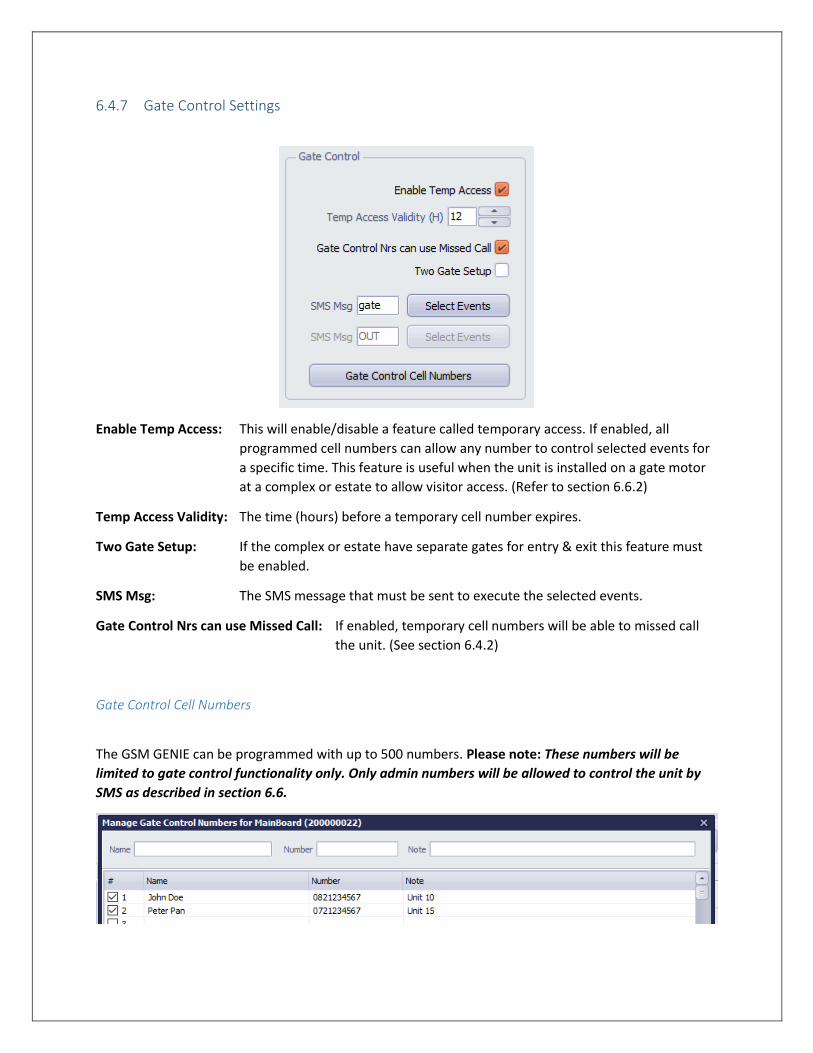
6.4.7 Gate Control Settings
Enable Temp Access: This will enable/disable a feature called temporary access. If enabled, all
programmed cell numbers can allow any number to control selected events for
a specific time. This feature is useful when the unit is installed on a gate motor
at a complex or estate to allow visitor access. (Refer to section 6.6.2)
Temp Access Validity: The time (hours) before a temporary cell number expires.
Two Gate Setup: If the complex or estate have separate gates for entry & exit this feature must
be enabled.
SMS Msg: The SMS message that must be sent to execute the selected events.
Gate Control Nrs can use Missed Call: If enabled, temporary cell numbers will be able to missed call
the unit. (See section 6.4.2)
Gate Control Cell Numbers
The GSM GENIE can be programmed with up to 500 numbers. Please note: These numbers will be
limited to gate control functionality only. Only admin numbers will be allowed to control the unit by
SMS as described in section 6.6.
6.5 Inputs & Outputs
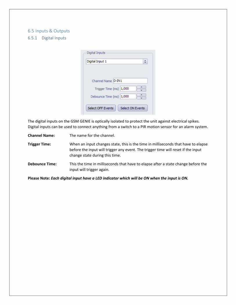
6.5.1 Digital Inputs
The digital inputs on the GSM GENIE is optically isolated to protect the unit against electrical spikes.
Digital inputs can be used to connect anything from a switch to a PIR motion sensor for an alarm system.
Channel Name: The name for the channel.
Trigger Time: When an input changes state, this is the time in milliseconds that have to elapse
before the input will trigger any event. The trigger time will reset if the input
change state during this time.
Debounce Time: This the time in milliseconds that have to elapse after a state change before the
input will trigger again.
Please Note: Each digital input have a LED indicator which will be ON when the input is ON.
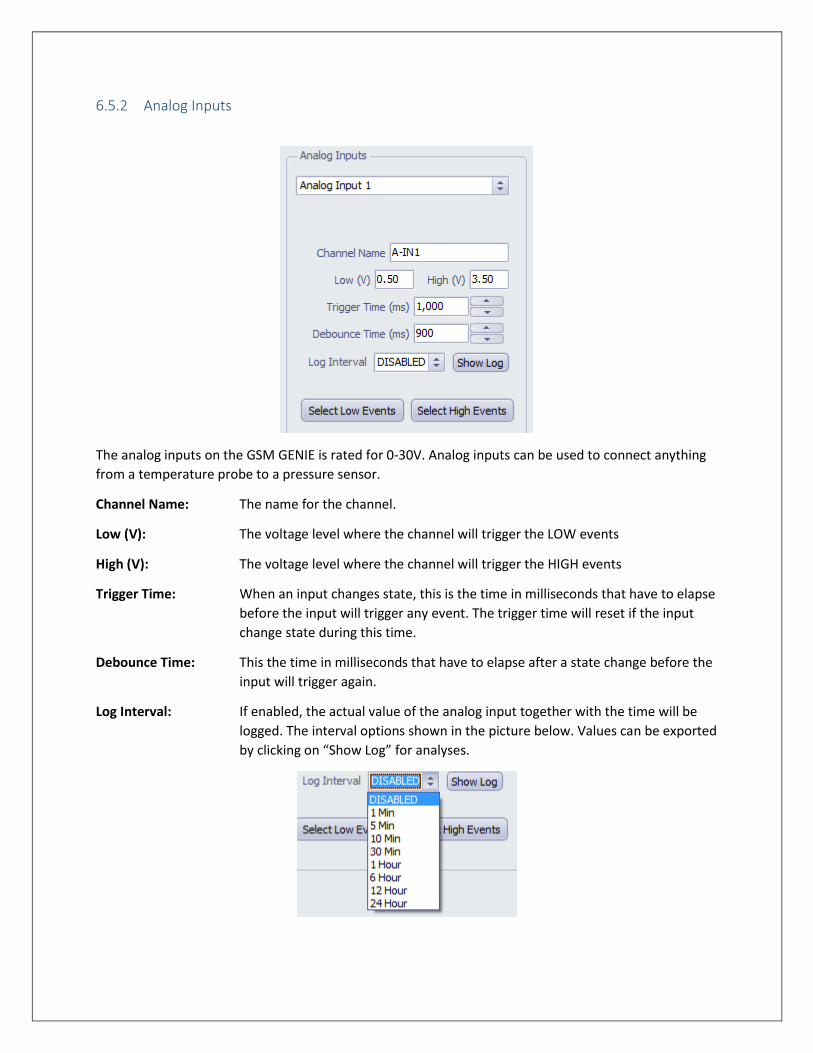
6.5.2 Analog Inputs
The analog inputs on the GSM GENIE is rated for 0-30V. Analog inputs can be used to connect anything
from a temperature probe to a pressure sensor.
Channel Name: The name for the channel.
Low (V): The voltage level where the channel will trigger the LOW events
High (V): The voltage level where the channel will trigger the HIGH events
Trigger Time: When an input changes state, this is the time in milliseconds that have to elapse
before the input will trigger any event. The trigger time will reset if the input
change state during this time.
Debounce Time: This the time in milliseconds that have to elapse after a state change before the
input will trigger again.
Log Interval: If enabled, the actual value of the analog input together with the time will be
logged. The interval options shown in the picture below. Values can be exported
by clicking on “Show Log” for analyses.
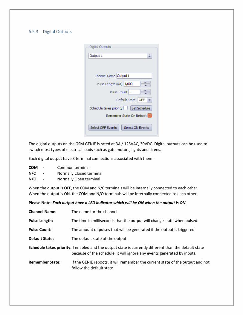
6.5.3 Digital Outputs
The digital outputs on the GSM GENIE is rated at 3A / 125VAC, 30VDC. Digital outputs can be used to
switch most types of electrical loads such as gate motors, lights and sirens.
Each digital output have 3 terminal connections associated with them:
COM - Common terminal
N/C - Normally Closed terminal
N/O - Normally Open terminal
When the output is OFF, the COM and N/C terminals will be internally connected to each other.
When the output is ON, the COM and N/O terminals will be internally connected to each other.
Please Note: Each output have a LED indicator which will be ON when the output is ON.
Channel Name: The name for the channel.
Pulse Length: The time in milliseconds that the output will change state when pulsed.
Pulse Count: The amount of pulses that will be generated if the output is triggered.
Default State: The default state of the output.
Schedule takes priority: If enabled and the output state is currently different than the default state
because of the schedule, it will ignore any events generated by inputs.
Remember State: If the GENIE reboots, it will remember the current state of the output and not
follow the default state.
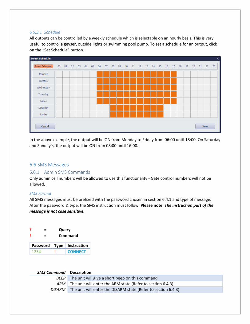
6.5.3.1 Schedule
All outputs can be controlled by a weekly schedule which is selectable on an hourly basis. This is very
useful to control a geyser, outside lights or swimming pool pump. To set a schedule for an output, click
on the “Set Schedule” button.
In the above example, the output will be ON from Monday to Friday from 06:00 until 18:00. On Saturday
and Sunday’s, the output will be ON from 08:00 until 16:00.
6.6 SMS Messages
6.6.1 Admin SMS Commands Only admin cell numbers will be allowed to use this functionality - Gate control numbers will not be
allowed.
SMS Format
All SMS messages must be prefixed with the password chosen in section 6.4.1 and type of message.
After the password & type, the SMS instruction must follow. Please note: The instruction part of the
message is not case sensitive.
? = Query
! = Command
SMS Command Description
BEEP The unit will give a short beep on this command
ARM The unit will enter the ARM state (Refer to section 6.4.3)
DISARM The unit will enter the DISARM state (Refer to section 6.4.3)
Password Type Instruction
1234 ! CONNECT
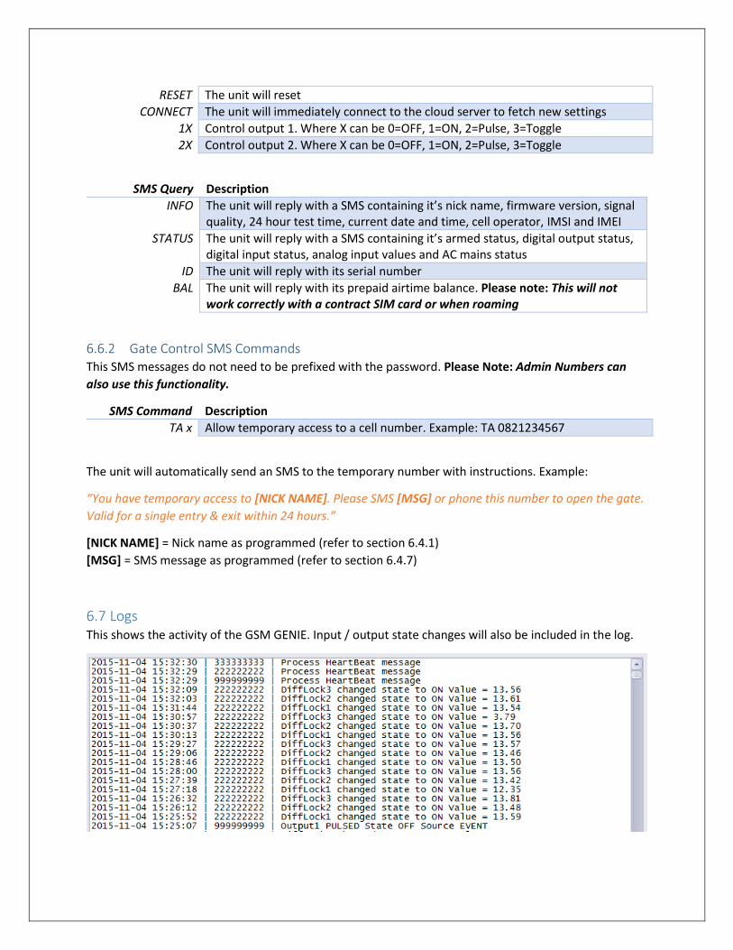
RESET The unit will reset
CONNECT The unit will immediately connect to the cloud server to fetch new settings
1X Control output 1. Where X can be 0=OFF, 1=ON, 2=Pulse, 3=Toggle
2X Control output 2. Where X can be 0=OFF, 1=ON, 2=Pulse, 3=Toggle
SMS Query Description
INFO The unit will reply with a SMS containing it’s nick name, firmware version, signal quality, 24 hour test time, current date and time, cell operator, IMSI and IMEI
STATUS The unit will reply with a SMS containing it’s armed status, digital output status, digital input status, analog input values and AC mains status
ID The unit will reply with its serial number
BAL The unit will reply with its prepaid airtime balance. Please note: This will not work correctly with a contract SIM card or when roaming
6.6.2 Gate Control SMS Commands This SMS messages do not need to be prefixed with the password. Please Note: Admin Numbers can
also use this functionality.
SMS Command Description
TA x Allow temporary access to a cell number. Example: TA 0821234567
The unit will automatically send an SMS to the temporary number with instructions. Example:
“You have temporary access to [NICK NAME]. Please SMS [MSG] or phone this number to open the gate.
Valid for a single entry & exit within 24 hours.”
[NICK NAME] = Nick name as programmed (refer to section 6.4.1)
[MSG] = SMS message as programmed (refer to section 6.4.7)
6.7 Logs This shows the activity of the GSM GENIE. Input / output state changes will also be included in the log.
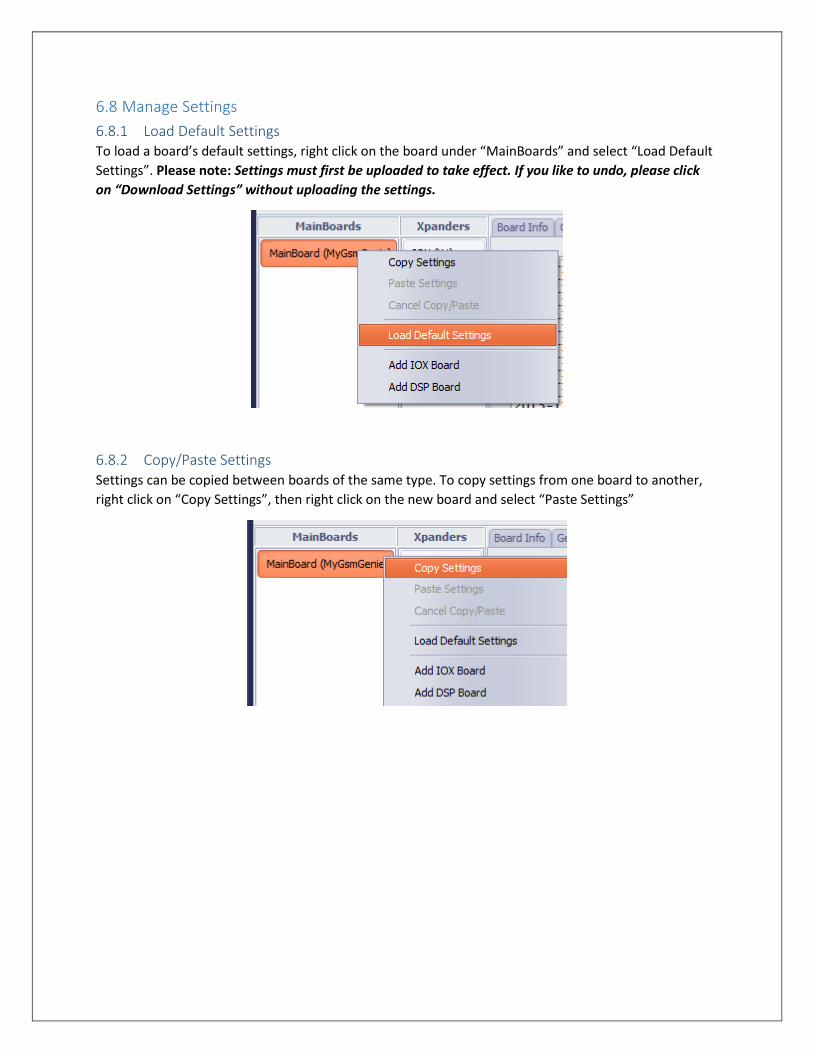
6.8 Manage Settings
6.8.1 Load Default Settings To load a board’s default settings, right click on the board under “MainBoards” and select “Load Default
Settings”. Please note: Settings must first be uploaded to take effect. If you like to undo, please click
on “Download Settings” without uploading the settings.
6.8.2 Copy/Paste Settings Settings can be copied between boards of the same type. To copy settings from one board to another,
right click on “Copy Settings”, then right click on the new board and select “Paste Settings”
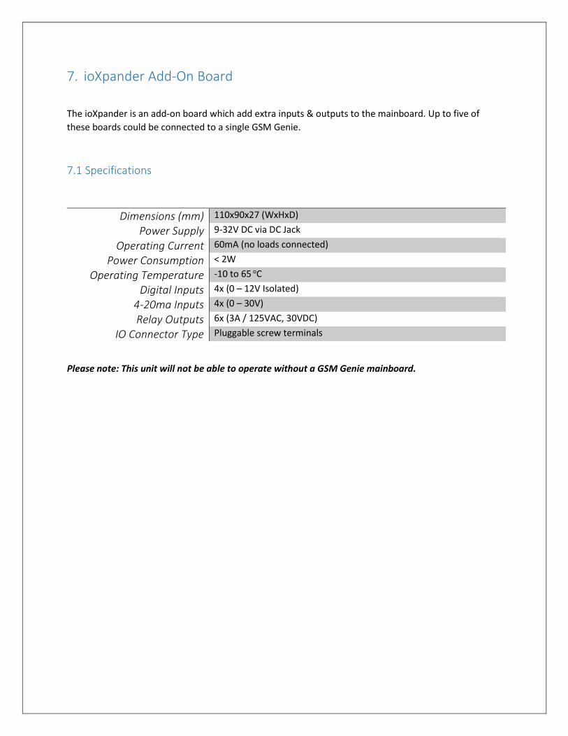
7. ioXpander Add-On Board
The ioXpander is an add-on board which add extra inputs & outputs to the mainboard. Up to five of
these boards could be connected to a single GSM Genie.
7.1 Specifications
Dimensions (mm) 110x90x27 (WxHxD)
Power Supply 9-32V DC via DC Jack
Operating Current 60mA (no loads connected)
Power Consumption < 2W
Operating Temperature -10 to 65 oC
Digital Inputs 4x (0 – 12V Isolated)
4-20ma Inputs 4x (0 – 30V)
Relay Outputs 6x (3A / 125VAC, 30VDC)
IO Connector Type Pluggable screw terminals
Please note: This unit will not be able to operate without a GSM Genie mainboard.
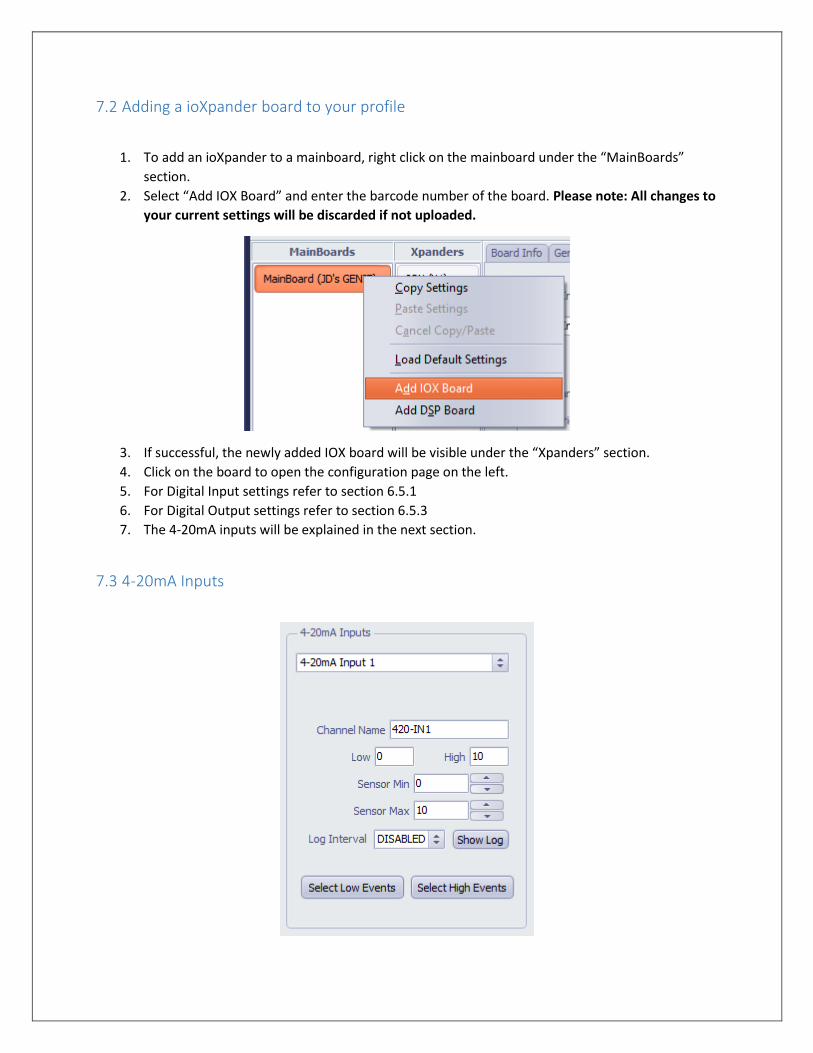
7.2 Adding a ioXpander board to your profile
1. To add an ioXpander to a mainboard, right click on the mainboard under the “MainBoards”
section.
2. Select “Add IOX Board” and enter the barcode number of the board. Please note: All changes to
your current settings will be discarded if not uploaded.
3. If successful, the newly added IOX board will be visible under the “Xpanders” section.
4. Click on the board to open the configuration page on the left.
5. For Digital Input settings refer to section 6.5.1
6. For Digital Output settings refer to section 6.5.3
7. The 4-20mA inputs will be explained in the next section.
7.3 4-20mA Inputs
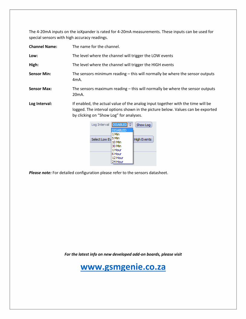
The 4-20mA inputs on the ioXpander is rated for 4-20mA measurements. These inputs can be used for
special sensors with high accuracy readings.
Channel Name: The name for the channel.
Low: The level where the channel will trigger the LOW events
High: The level where the channel will trigger the HIGH events
Sensor Min: The sensors minimum reading – this will normally be where the sensor outputs
4mA.
Sensor Max: The sensors maximum reading – this will normally be where the sensor outputs
20mA.
Log Interval: If enabled, the actual value of the analog input together with the time will be
logged. The interval options shown in the picture below. Values can be exported
by clicking on “Show Log” for analyses.
Please note: For detailed configuration please refer to the sensors datasheet.
For the latest info on new developed add-on boards, please visit
www.gsmgenie.co.za