Embed Size (px)
DESCRIPTION
Group Services and System Aspects
Citation preview
3GPP TS 43.020 V4.0.0 (2000-11)Technical Specification
3rd Generation Partnership Project;Technical Specification Group Services and system Aspects;
Security related network functions(Release 4)
GLOBAL SYSTEM FOR MOBILE COMMUNICATIONS
R
The present document has been developed within the 3rd Generation Partnership Project (3GPP TM) and may be further elaborated for the purposes of 3GPP.
The present document has not been subject to any approval process by the 3GPP Organisational Partners and shall not be implemented. This Specification is provided for future development work within 3GPP only. The Organisational Partners accept no liability for any use of this Specification.Specifications and reports for implementation of the 3GPP TM system should be obtained via the 3GPP Organisational Partners' Publications Offices.
Keywords3GPP, GSM, Security
3GPP
Postal address
3GPP support office address650 Route des Lucioles - Sophia Antipolis
Valbonne - FRANCETel.: +33 4 92 94 42 00 Fax: +33 4 93 65 47 16
Internethttp://www.3gpp.org
Copyright Notification
No part may be reproduced except as authorized by written permission.The copyright and the foregoing restriction extend to reproduction in all media.
© 2000, 3GPP Organizational Partners (ARIB, CWTS, ETSI, T1, TTA,TTC).All rights reserved.
3GPP TS 43.020 V4.0.0 (2000-11)2Release 4
Contents
Foreword.....................................................................................................................................................7
0 Scope.................................................................................................................................................80.1 References...................................................................................................................................................80.2 Abbreviations..............................................................................................................................................9
1 General..............................................................................................................................................9
2 Subscriber identity confidentiality..................................................................................................102.1 Generality..................................................................................................................................................102.2 Identifying method....................................................................................................................................102.3 Procedures.................................................................................................................................................102.3.1 Location updating in the same MSC area............................................................................................102.3.2 Location updating in a new MSCs area, within the same VLR area...................................................112.3.3 Location updating in a new VLR; old VLR reachable........................................................................122.3.4 Location Updating in a new VLR; old VLR not reachable.................................................................132.3.5 Reallocation of a new TMSI................................................................................................................142.3.6 Local TMSI unknown..........................................................................................................................152.3.7 Location updating in a new VLR in case of a loss of information......................................................162.3.8 Unsuccessful TMSI allocation............................................................................................................162.3.9 Combined location area updating with the routing area updating.......................................................17
3 Subscriber identity authentication...................................................................................................183.1 Generality..................................................................................................................................................183.2 The authentication procedure....................................................................................................................183.3 Subscriber Authentication Key management............................................................................................193.3.1 General authentication procedure........................................................................................................193.3.2 Authentication at location updating in a new VLR, using TMSI........................................................203.3.3 Authentication at location updating in a new VLR, using IMSI.........................................................213.3.4 Authentication at location updating in a new VLR, using TMSI, TMSI unknown in "old" VLR......223.3.5 Authentication at location updating in a new VLR, using TMSI, old VLR not reachable.................233.3.6 Authentication with IMSI if authentication with TMSI fails..............................................................233.3.7 Re-use of security related information in failure situations................................................................23
4 Confidentiality of signalling information elements, connectionless data and user information elements on physical connections...................................................................................................24
4.1 Generality..................................................................................................................................................244.2 The ciphering method...............................................................................................................................254.3 Key setting................................................................................................................................................254.4 Ciphering key sequence number...............................................................................................................264.5 Starting of the ciphering and deciphering processes.................................................................................264.6 Synchronization.........................................................................................................................................264.7 Handover...................................................................................................................................................264.8 Negotiation of A5 algorithm.....................................................................................................................27
5 Synthetic summary..........................................................................................................................28
Annex A (informative): Security issues related to signalling schemes and key management..29
A.1 Introduction.....................................................................................................................................29
A.2 Short description of the schemes....................................................................................................29
A.3 List of abbreviations........................................................................................................................30
Annex B (informative): Security information to be stored in the entities of the GSM system 44
B.1 Introduction.....................................................................................................................................44
B.2 Entities and security information....................................................................................................44B.2.1 Home Location Register (HLR)................................................................................................................44
3GPP TS 43.020 V4.0.0 (2000-11)3Release 4
B.2.2 Visitor Location Register (VLR)..............................................................................................................44B.2.3 Mobile services Switching Centre (MSC)/Base Station System (BSS)....................................................44B.2.4 Mobile Station (MS).................................................................................................................................45B.2.5 Authentication Centre (AuC)....................................................................................................................45
Annex C (normative): External specifications of security related algorithms........................46
C.0 Scope...............................................................................................................................................46
C.1 Specifications for Algorithm A5.....................................................................................................46C.1.1 Purpose......................................................................................................................................................46C.1.2 Implementation indications.......................................................................................................................46C.1.3 External specifications of Algorithm A5..................................................................................................48C.1.4 Internal specification of Algorithm A5.....................................................................................................48C.1.5 A modification of the usage of A5 for EDGE...........................................................................................48
C.2 Algorithm A3..................................................................................................................................48C.2.1 Purpose......................................................................................................................................................48C.2.2 Implementation and operational requirements..........................................................................................49
C.3 Algorithm A8..................................................................................................................................49C.3.1 Purpose......................................................................................................................................................49C.3.2 Implementation and operational requirements..........................................................................................49
Annex D (normative): Security related network functions for General Packet Radio Service50
D.1 General............................................................................................................................................50
D.2 Subscriber identity confidentiality..................................................................................................50D.2.1 Generality..................................................................................................................................................50D.2.2 Identifying method....................................................................................................................................51D.2.3 Procedures.................................................................................................................................................51D.2.3.1 Routing area updating in the same SGSN area...................................................................................51D.2.3.2 Routing area updating in a new SGSN; old SGSN reachable.............................................................52D.2.3.3 Routing area updating in a new SGSN; old SGSN not reachable.......................................................53D.2.3.4 Reallocation of a TLLI........................................................................................................................53D.2.3.5 Local TLLI unknown..........................................................................................................................54D.2.3.6 Routing area updating in a new SGSN in case of a loss of information.............................................55D.2.3.7 Unsuccessful TLLI allocation.............................................................................................................55
D.3 Subscriber identity authentication...................................................................................................56D.3.1 Generality..................................................................................................................................................56D.3.2 The authentication procedure....................................................................................................................56D.3.3 Subscriber Authentication Key management............................................................................................56D.3.3.1 General authentication procedure........................................................................................................56D.3.3.2 Authentication at routing area updating in a new SGSN, using TLLI................................................57D.3.3.3 Authentication at routing area updating in a new SGSN, using IMSI................................................58D.3.3.4 Authentication at routing area updating in a new SGSN, using TLLI, TLLI unknown in 'old' SGSN59D.3.3.5 Authentication at routing area updating in a new SGSN, using TLLI, old SGSN not reachable.......60D.3.3.6 Authentication with IMSI if authentication with TLLI fails...............................................................60D.3.3.7 Re-use of security related information in failure situations................................................................60
D.4 Confidentiality of user information and signalling between MS and SGSN..................................61D.4.1 Generality..................................................................................................................................................61D.4.2 The ciphering method...............................................................................................................................61D.4.3 Key setting................................................................................................................................................62D.4.4 Ciphering key sequence number...............................................................................................................62D.4.5 Starting of the ciphering and deciphering processes.................................................................................63D.4.6 Synchronisation.........................................................................................................................................63D.4.7 Inter SGSN routing area update................................................................................................................64D.4.8 Negotiation of GPRS-A5 algorithm..........................................................................................................64
3GPP TS 43.020 V4.0.0 (2000-11)4Release 4
D.5 Synthetic summary..........................................................................................................................65
D.6 Security of the GPRS backbone......................................................................................................65
Annex E (normative): GSM Cordless Telephony System (CTS), (Phase 1); Security related network functions; Stage 2....................................................................66
E.1 Introduction.....................................................................................................................................66E.1.1 Scope.........................................................................................................................................................66E.1.2 References.................................................................................................................................................66E.1.3 Definitions and Abbreviations..................................................................................................................66E.1.3.1 Definitions...........................................................................................................................................66E.1.3.2 Abbreviations......................................................................................................................................67
E.2 General............................................................................................................................................68
E.3 CTS local security system...............................................................................................................69E.3.1 Mobile Subscriber identity confidentiality................................................................................................69E.3.1.1 Identifying method..............................................................................................................................69E.3.1.2 Procedures...........................................................................................................................................69E.3.1.2.1 CTSMSI assignment......................................................................................................................69E.3.1.2.2 CTSMSI update.............................................................................................................................70E.3.1.2.3 CTS local identification.................................................................................................................70E.3.2 Identity authentication...............................................................................................................................70E.3.2.1 The mutual authentication procedure..................................................................................................70E.3.2.1.1 Authentication failure....................................................................................................................71E.3.2.2 Authentication Key management........................................................................................................71E.3.3 Confidentiality of user information and signalling between CTS-MS and CTS-FP................................72E.3.3.1 The ciphering method..........................................................................................................................72E.3.3.2 Key setting...........................................................................................................................................72E.3.3.3 Starting of the ciphering and deciphering processes...........................................................................73E.3.3.4 Synchronisation...................................................................................................................................74E.3.4 Structured procedures with CTS local security relevance........................................................................74E.3.4.1 Local Part of the Enrolment of a CTS-MS onto a CTS-FP.................................................................74E.3.4.1.1 Local part of the enrolment procedure...........................................................................................75E.3.4.2 General Access procedure...................................................................................................................77E.3.4.2.1 Attachment.....................................................................................................................................77E.3.4.2.2 CTS local security data update......................................................................................................78E.3.4.3 De-enrolment of a CTS-MS................................................................................................................78E.3.4.3.1 De-enrolment initiated by the CTS-FP..........................................................................................78E.3.4.3.2 De-enrolment initiated by a CTS-MS............................................................................................78
E.4 CTS supervising security system....................................................................................................79E.4.1 Supervision data and supervision data protection.....................................................................................79E.4.1.1 Structure of supervision data...............................................................................................................79E.4.1.2 Supervision data protection.................................................................................................................79E.4.1.3 Key management.................................................................................................................................80E.4.2 CTS subscriber identity.............................................................................................................................80E.4.3 Identity authentication with the CTS operator and the PLMN.................................................................80E.4.3.1 Authentication of the CTS-FP.............................................................................................................81E.4.3.2 Authentication of the CTS-MS............................................................................................................81E.4.4 Secure operation control...........................................................................................................................82E.4.4.1 GSM layer 3 signalling........................................................................................................................82E.4.4.2 CTS application signalling via the Fixed Network.............................................................................82E.4.4.3 CTS operation control procedures.......................................................................................................83E.4.4.3.1 Initialisation of a CTS-FP..............................................................................................................83E.4.4.3.2 De-initialisation of a CTS-FP........................................................................................................83E.4.4.3.3 Enrolment.......................................................................................................................................84E.4.4.3.3.1 Enrolment conducted via the CTS fixed network interface.....................................................84E.4.4.3.4 Supervising security in the CTS-FP/CTS-SN access procedure...................................................85E.4.4.3.4.1 Update of operation data..........................................................................................................85E.4.5 Equipment checking..................................................................................................................................86E.4.6 FP-SIM card checking...............................................................................................................................86
3GPP TS 43.020 V4.0.0 (2000-11)5Release 4
E.5 Other CTS security features............................................................................................................87E.5.1 Secure storage of sensitive data and software in the CTS-MS.................................................................87E.5.1.1 Inside CTS-ME....................................................................................................................................87E.5.2 Secure storage of sensitive data and software in CTS-FP.........................................................................87E.5.3 CTS-FP reprogramming protection...........................................................................................................87
E.6 FP Integrity.....................................................................................................................................87E.6.1 Threats.......................................................................................................................................................88E.6.1.1 Changing of FP software.....................................................................................................................88E.6.1.2 Changing of IFPEI...............................................................................................................................89E.6.1.3 Changing of IFPSI and operator and subscription related keys (KiFP, KOP)........................................89E.6.1.4 Changing of timers and timer limits....................................................................................................89E.6.1.5 Changing of radio usage parameters...................................................................................................89E.6.2 Protection and storage mechanisms..........................................................................................................89E.6.2.1 Static or semi static values..................................................................................................................89E.6.2.2 Timers..................................................................................................................................................89E.6.2.3 Physical protection..............................................................................................................................89
E.7 Type approval issues.......................................................................................................................89
E.8 Security information to be stored in the entities of the CTS...........................................................90E.8.1 Entities and security information..............................................................................................................90E.8.1.1 CTS-HLR............................................................................................................................................90E.8.1.2 CTS-SN...............................................................................................................................................90E.8.1.3 CTS-AuC.............................................................................................................................................90E.8.1.4 CTS Fixed Part Equipment (CTS-FPE)..............................................................................................91E.8.1.5 Fixed Part SIM card (FP-SIM)............................................................................................................91E.8.1.6 CTS Mobile Equipment (CTS-ME)....................................................................................................91E.8.1.7 Mobile Station SIM card (MS-SIM)...................................................................................................91
E.9 External specification of security related algorithms......................................................................92E.9.1 Algorithm B1............................................................................................................................................92E.9.1.1 Purpose................................................................................................................................................92E.9.1.2 Implementation and operational requirements....................................................................................93E.9.2 Algorithm B2............................................................................................................................................93E.9.2.1 Purpose................................................................................................................................................93E.9.2.2 Implementation and operational requirements....................................................................................93E.9.3 Algorithms B3 and B4..............................................................................................................................94E.9.3.1 Purpose................................................................................................................................................94E.9.3.2 Implementation and operational requirements....................................................................................94E.9.4 Algorithms B5 and B6..............................................................................................................................94E.9.4.1 Purpose................................................................................................................................................94E.9.4.2 Implementation and operational requirements....................................................................................94
E.10 Coding of the FPAC and CTS-PIN.................................................................................................95
E.11 (informative annex): Guidelines for generation of random numbers.............................................95
Annex F (informative): Change History.......................................................................................96
3GPP TS 43.020 V4.0.0 (2000-11)6Release 4
ForewordThis Technical Specification has been produced by the 3rd Generation Partnership Project (3GPP).
The contents of the present document are subject to continuing work within the TSG and may change following formal TSG approval. Should the TSG modify the contents of the present document, it will be re-released by the TSG with an identifying change of release date and an increase in version number as follows:
Version x.y.z
where:
x the first digit:
1 presented to TSG for information;
2 presented to TSG for approval;
3 or greater indicates TSG approved document under change control.
y the second digit is incremented for all changes of substance, i.e. technical enhancements, corrections, updates, etc.
z the third digit is incremented when editorial only changes have been incorporated in the document.
3GPP TS 43.020 V4.0.0 (2000-11)7Release 4
0 ScopeThis Technical Specification specifies the network functions needed to provide the security related service and functions specified in GSM 02.09.
This specification does not address the cryptological algorithms that are needed to provide different security related features. This topic is addressed in annex C. Wherever a cryptological algorithm or mechanism is needed, this is signalled with a reference to annex C. The references refers only to functionalities, and some algorithms may be identical or use common hardware.
0.1 ReferencesThe following documents contain provisions which, through reference in this text, constitute provisions of the present document.
References are either specific (identified by date of publication, edition number, version number, etc.) or non-specific.
For a specific reference, subsequent revisions do not apply.
For a non-specific reference, the latest version applies.
[1] GSM 01.04: "Digital cellular telecommunications system (Phase 2+); Abbreviations and acronyms".
[2] GSM 01.61: "Digital cellular telecommunications system (Phase 2+); General Packet Radio Service (GPRS); GPRS ciphering algorithm requirements".
[3] GSM 02.07: "Digital cellular telecommunications system (Phase 2+); Mobile Station (MS) features".
[4] GSM 02.09: "Digital cellular telecommunications system (Phase 2+); Security aspects".
[5] GSM 02.17: "Digital cellular telecommunications system (Phase 2+); Subscriber Identity Modules (SIM) Functional characteristics".
[6] GSM 02.56: "Digital cellular telecommunications system (Phase 2+); GSM Cordless Telephone System (CTS) Phase 1; Service Description; Stage 1".
[7] GSM 02.60: " Digital cellular telecommunications system (Phase 2+); General Packet Radio Service (GPRS); Service description; Stage 1".
[8] GSM 03.03: "Digital cellular telecommunications system (Phase 2+); Numbering, addressing and identification".
9 GSM 03.56: "Digital cellular telecommunications system (Phase 2+); GSM Cordless Telephone System (CTS), Phase 1; CTS Architecture Description; Stage 2".
[10] GSM 03.60: " Digital cellular telecommunications system (Phase 2+); General Packet Radio Service (GPRS); Service description; Stage 2".
[11] GSM 04.08: "Digital cellular telecommunications system (Phase 2+); Mobile radio interface layer 3 specification".
[12] GSM 04.64: " Digital cellular telecommunications system (Phase 2+), General Packet Radio Service (GPRS); Logical Link Control (LLC)".
[13] GSM 05.01: "Digital cellular telecommunication system (Phase 2+); Physical layer on the radio path; General description".
[14] GSM 05.02: "Digital cellular telecommunications system (Phase 2+); Multiplexing and multiple access on the radio path".
3GPP TS 43.020 V4.0.0 (2000-11)8Release 4

[15] GSM 05.03: "Digital cellular telecommunications system (Phase 2+); Channel coding".
[16] GSM 09.02: "Digital cellular telecommunications system (Phase 2+); Mobile Application Part (MAP) specification".
17 GSM 11.11: "Digital cellular telecommunications system (Phase 2+); Specification of the Subscriber Identity Module- Mobile Equipment (SIM-ME) interface".
0.2 AbbreviationsAbbreviations used in this specification are listed in GSM 01.04.
Specific abbreviations used in annex A are listed in clause A.3.
Specific CTS related abbreviations used in annex E are listed in clause E.1.3.
1 GeneralThe different security related services and functions that are listed in GSM 02.09 are grouped as follows:
- Subscriber identity confidentiality;
- Subscriber identity authentication;
- Signalling information element and connectionless user data confidentiality and data confidentiality for physical connections (ciphering).
It shall be possible to introduce new authentication and ciphering algorithms during the systems lifetime. The fixed network may support more than one authentication and ciphering algorithm.
The security procedures include mechanisms to enable recovery in event of signalling failures. These recovery procedures are designed to minimize the risk of a breach in the security of the system.
General on figures in this specification:
- In the figures below, signalling exchanges are referred to by functional names. The exact messages and message types are specified in GSM 04.08 and GSM 09.02.
- No assumptions are made for function splitting between MSC (Mobile Switching Centre), VLR (Visitor Location Register) and BSS (Base Station System). Signalling is described directly between MS and the local network (i.e. BSS, MSC and VLR denoted in the figures by BSS/MSC/VLR). The splitting in annex A is given only for illustrative purposes.
- Addressing fields are not given; all information relates to the signalling layer. The TMSI allows addressing schemes without IMSI, but the actual implementation is specified in the GSM 04-series.
- The term HPLMN in the figures below is used as a general term which should be understood as HLR (Home Location Register) or AuC (Authentication Centre).
- What is put in a box is not part of the described procedure but it is relevant to the understanding of the figure.
3GPP TS 43.020 V4.0.0 (2000-11)9Release 4
2 Subscriber identity confidentiality
2.1 GeneralityThe purpose of this function is to avoid the possibility for an intruder to identify which subscriber is using a given resource on the radio path (e.g. TCH (Traffic Channel) or signalling resources) by listening to the signalling exchanges on the radio path. This allows both a high level of confidentiality for user data and signalling and protection against the tracing of a user's location.
The provision of this function implies that the IMSI (International Mobile Subscriber Identity), or any information allowing a listener to derive the IMSI easily, should not normally be transmitted in clear text in any signalling message on the radio path.
Consequently, to obtain the required level of protection, it is necessary that:
- a protected identifying method is normally used instead of the IMSI on the radio path; and
- the IMSI is not normally used as addressing means on the radio path (see GSM 02.09);
- when the signalling procedures permit it, signalling information elements that convey information about the mobile subscriber identity must be ciphered for transmission on the radio path.
The identifying method is specified in the following subclause. The ciphering of communication over the radio path is specified in clause 4.
2.2 Identifying methodThe means used to identify a mobile subscriber on the radio path consists of a TMSI (Temporary Mobile Subscriber Identity). This TMSI is a local number, having a meaning only in a given location area; the TMSI must be accompanied by the LAI (Location Area Identification) to avoid ambiguities. The maximum length and guidance for defining the format of a TMSI are specified in GSM 03.03.
The network (e.g. a VLR) manages suitable data bases to keep the relation between TMSIs and IMSIs. When a TMSI is received with an LAI that does not correspond to the current VLR, the IMSI of the MS must be requested from the VLR in charge of the indicated location area if its address is known; otherwise the IMSI is requested from the MS.
A new TMSI must be allocated at least in each location updating procedure. The allocation of a new TMSI corresponds implicitly for the MS to the de-allocation of the previous one. In the fixed part of the network, the cancellation of the record for an MS in a VLR implies the de-allocation of the corresponding TMSI.
To cope with some malfunctioning, e.g. arising from a software failure, the fixed part of the network can require the identification of the MS in clear. This procedure is a breach in the provision of the service, and should be used only when necessary.
When a new TMSI is allocated to an MS, it is transmitted to the MS in a ciphered mode. This ciphered mode is the same as defined in clause 4.
The MS must store its current TMSI in a non volatile memory, together with the LAI, so that these data are not lost when the MS is switched off.
2.3 ProceduresThis subclause presents the procedures, or elements of procedures, pertaining to the management of TMSIs.
2.3.1 Location updating in the same MSC areaThis procedure is part of the location updating procedure which takes place when the original location area and the new location area depend on the same MSC. The part of this procedure relative to TMSI management is reduced to a TMSI re-allocation (from TMSIo with "o" for "old" to TMSIn with "n" for "new").
3GPP TS 43.020 V4.0.0 (2000-11)10Release 4
The MS sends TMSIo as an identifying field at the beginning of the location updating procedure.
The procedure is schematized in figure 2.1.
Figure 2.1: Location updating in the same MSC area
Signalling Functionalities:
Management of means for new ciphering:
The MS and BSS/MSC/VLR agree on means for ciphering signalling information elements, in particular to transmit TMSIn.
2.3.2 Location updating in a new MSCs area, within the same VLR areaThis procedure is part of the location updating procedure which takes place when the original location area and the new location area depend on different MSCs, but on the same VLR.
The procedure is schematized on figure 2.2.
3GPP TS 43.020 V4.0.0 (2000-11)11Release 4

NOTE: From a security point of view, the order of the procedures is irrelevant.
Figure 2.2: Location updating in a new MSCs area, within the same VLR area
Signalling functionalities:
Loc.Updating:
stands for Location Updating
The BSS/MSC/VLR indicates that the location of the MS must be updated.
2.3.3 Location updating in a new VLR; old VLR reachableThis procedure is part of the normal location updating procedure, using TMSI and LAI, when the original location area and the new location area depend on different VLRs.
The MS is still registered in VLRo ("o" for old or original) and requests registration in VLRn ("n" for new). LAI and TMSIo are sent by MS as identifying fields during the location updating procedure.
The procedure is schematized in figure 2.3.
3GPP TS 43.020 V4.0.0 (2000-11)12Release 4
NOTE: From a security point of view, the order of the procedures is irrelevant.
Figure 2.3: Location updating in a new VLR; old VLR reachable
Signalling functionalities:
Sec.Rel.Info.:
Stands for Security Related information
The MSC/VLRn needs some information for authentication and ciphering; this information is obtained from MSC/VLRo.
Cancellation:
The HLR indicates to VLRo that the MS is now under control of another VLR. The "old" TMSI is free for allocation.
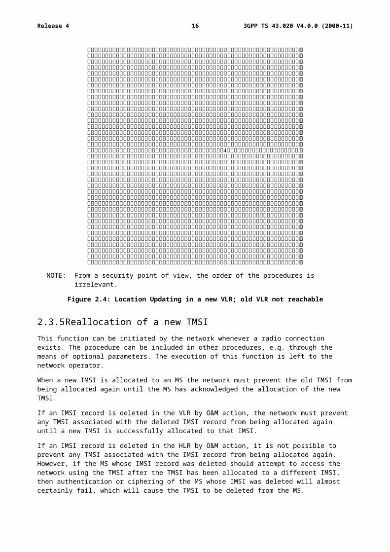
2.3.4 Location Updating in a new VLR; old VLR not reachableThis variant of the procedure in subclause 2.3.3 arises when the VLR receiving the LAI and TMSIo cannot identify the VLRo. In that case the relation between TMSIo and IMSI is lost, and the identification of the MS in clear is necessary.
The procedure is schematized in figure 2.4
3GPP TS 43.020 V4.0.0 (2000-11)13Release 4
NOTE: From a security point of view, the order of the procedures is irrelevant.
Figure 2.4: Location Updating in a new VLR; old VLR not reachable
2.3.5 Reallocation of a new TMSIThis function can be initiated by the network whenever a radio connection exists. The procedure can be included in other procedures, e.g. through the means of optional parameters. The execution of this function is left to the network operator.
When a new TMSI is allocated to an MS the network must prevent the old TMSI from being allocated again until the MS has acknowledged the allocation of the new TMSI.
If an IMSI record is deleted in the VLR by O&M action, the network must prevent any TMSI associated with the deleted IMSI record from being allocated again until a new TMSI is successfully allocated to that IMSI.
If an IMSI record is deleted in the HLR by O&M action, it is not possible to prevent any TMSI associated with the IMSI record from being allocated again. However, if the MS whose IMSI record was deleted should attempt to access the network using the TMSI after the TMSI has been allocated to a different IMSI, then authentication or ciphering of the MS whose IMSI was deleted will almost certainly fail, which will cause the TMSI to be deleted from the MS.
The case where allocation of a new TMSI is unsuccessful is described in subclause 2.3.8.
This procedure is schematized in figure 2.5.
3GPP TS 43.020 V4.0.0 (2000-11)14Release 4
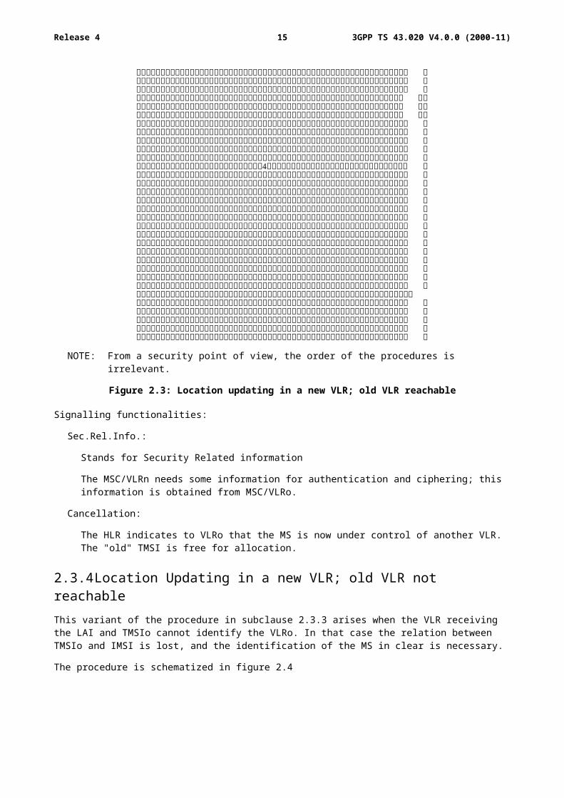
Figure 2.5: Reallocation of a new TMSI
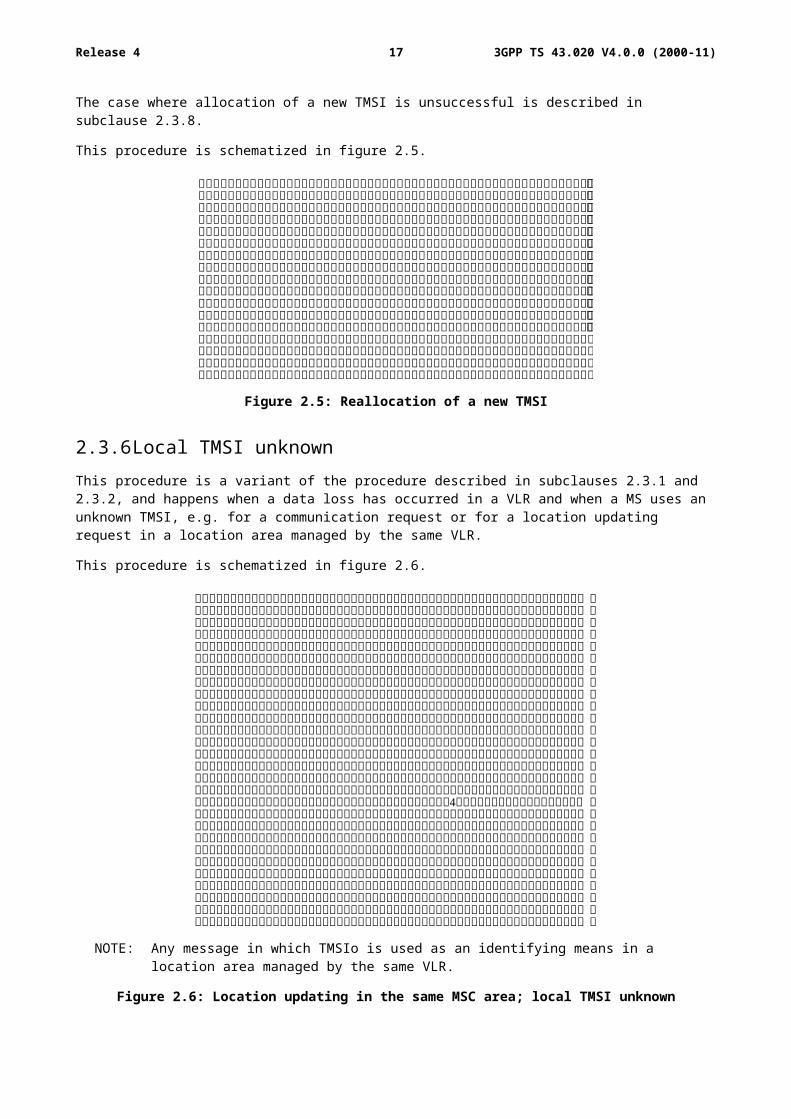
2.3.6 Local TMSI unknownThis procedure is a variant of the procedure described in subclauses 2.3.1 and 2.3.2, and happens when a data loss has occurred in a VLR and when a MS uses an unknown TMSI, e.g. for a communication request or for a location updating request in a location area managed by the same VLR.
This procedure is schematized in figure 2.6.
NOTE: Any message in which TMSIo is used as an identifying means in a location area managed by the same VLR.
Figure 2.6: Location updating in the same MSC area; local TMSI unknown
3GPP TS 43.020 V4.0.0 (2000-11)15Release 4
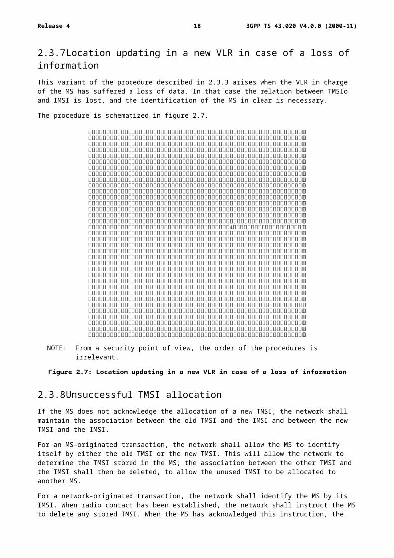
2.3.7 Location updating in a new VLR in case of a loss of informationThis variant of the procedure described in 2.3.3 arises when the VLR in charge of the MS has suffered a loss of data. In that case the relation between TMSIo and IMSI is lost, and the identification of the MS in clear is necessary.
The procedure is schematized in figure 2.7.
NOTE: From a security point of view, the order of the procedures is irrelevant.
Figure 2.7: Location updating in a new VLR in case of a loss of information
2.3.8 Unsuccessful TMSI allocationIf the MS does not acknowledge the allocation of a new TMSI, the network shall maintain the association between the old TMSI and the IMSI and between the new TMSI and the IMSI.
For an MS-originated transaction, the network shall allow the MS to identify itself by either the old TMSI or the new TMSI. This will allow the network to determine the TMSI stored in the MS; the association between the other TMSI and the IMSI shall then be deleted, to allow the unused TMSI to be allocated to another MS.
For a network-originated transaction, the network shall identify the MS by its IMSI. When radio contact has been established, the network shall instruct the MS to delete any stored TMSI. When the MS has acknowledged this instruction, the network shall delete the association between the IMSI of the MS and any TMSI; this will allow the released TMSIs to be allocated to another MS.
In either of the cases above, the network may initiate the normal TMSI reallocation procedure.
Repeated failure of TMSI reallocation (passing a limit set by the operator) may be reported for O&M action.
3GPP TS 43.020 V4.0.0 (2000-11)16Release 4
2.3.9 Combined location area updating with the routing area updatingThis subclause is only applicable if GPRS is supported.
This procedure is part of the location updating of a General Packet Radio Service (GPRS) class A or B mobile when the Gs-interface (SGSN MSC/VLR signalling interface) is implemented. This procedure is not relevant if the Gs-interface is not implemented.
The location area updating procedure and the routing area updating procedure are combined to one MS Serving GPRS Support Node (SGSN) procedure. The MS includes a Location Area Update (LAU) indication in the Routing Area Update Request message. The SGSN performs the location updating towards the VLR on behalf of the MS.
The procedure described in figure 2.8 shows only the interaction between the SGSN and the VLR. The full procedure including the update to other network element (e.g. HLR, old MSC/VLR) is described in GSM 03.60 .
MS BSS SGSN VLR
RAI, TLLI, LAU indication
-------------------------------------->
(note 1)
Securityfunctions
IMSI,LAI (note 2)
------------------------------------->
Allocationof TMSIn
TMSIn (note 3)
<-------------------------------------
Cipher(TMSIn) (note 4)
<--------------------------------------
Acknowledge (note 5) Acknowledge (note 6)
--------------------------------------> ------------------------------------->
Deallocationof TMSIo
3GPP TS 43.020 V4.0.0 (2000-11)17Release 4
NOTE 1: The Routeing Area Update Request message including the old Routing Area Identifier (RAI), the Temporary Logical Link Identifier (TLLI), and an indication that a combined Location Area Update (LAU) is performed.
NOTE 2: Location Updating message.
NOTE 3: Location Updating Accept message including the new TMSI.
NOTE 4: Routing Area Update Accept message including the new TMSI and the new TLLI (if any).
NOTE 5: Routing Area Update Complete message including the TLLI and TMSI.
NOTE 6: TMSI Reallocation Complete message including the TMSI.
Figure 2.8: Combined routing area and location updating in the same VLR
When the VLR does not change the TMSI, the old TMSI will stay in use and there is no need to send any TMSI to the MS.
In case of combined routing area update and inter-VLR location area updating procedure, the old TMSI will be cancelled and the HLR is updated as described in GSM 03.60.
If the Location Updating message indicates a reject (if for example the MS try to enter a forbidden location area), then this should be indicated to the MS and the MS shall not access non-GPRS service until a successful Location Update is performed.
For the combined location and routing area update and the combined GPRS Attach and IMSI Attach for GPRS class A and B mobiles, the authentication is performed by the SGSN. The authentication procedure for GPRS is described in annex D. The MSC/VLR relies on the SGSN authentication. This authentication procedure generates no ciphering key for circuit switched ciphering.
The ciphering key for circuit switched operation is allocated through an authentication by MSC/VLR when the circuit switched service is requested. Also, the MSC/VLR may use the old ciphering key if existing.
3 Subscriber identity authentication
3.1 GeneralityThe definition and operational requirements of subscriber identity authentication are given in GSM 02.09.
The authentication procedure will also be used to set the ciphering key (see clause 4). Therefore, it is performed after the subscriber identity (TMSI/IMSI) is known by the network and before the channel is encrypted.
Two network functions are necessary: the authentication procedure itself, and the key management inside the fixed subsystem.
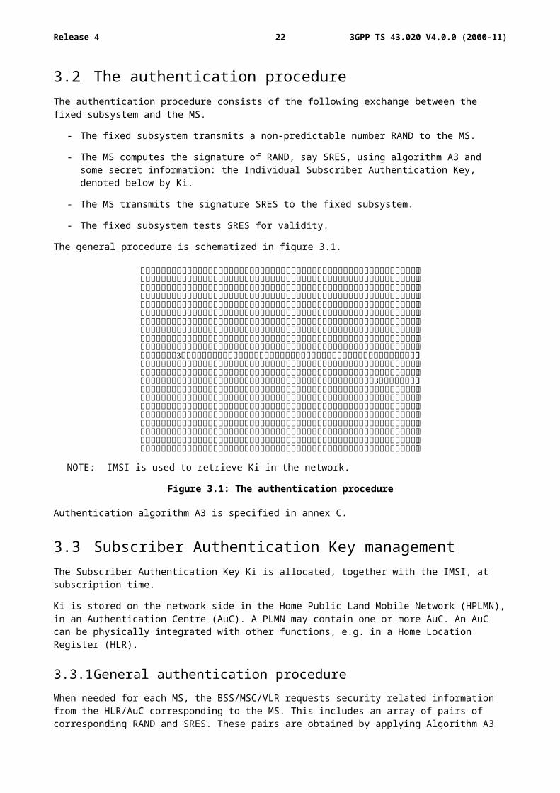
3.2 The authentication procedureThe authentication procedure consists of the following exchange between the fixed subsystem and the MS.
- The fixed subsystem transmits a non-predictable number RAND to the MS.
- The MS computes the signature of RAND, say SRES, using algorithm A3 and some secret information: the Individual Subscriber Authentication Key, denoted below by Ki.
- The MS transmits the signature SRES to the fixed subsystem.
- The fixed subsystem tests SRES for validity.
The general procedure is schematized in figure 3.1.
3GPP TS 43.020 V4.0.0 (2000-11)18Release 4
NOTE: IMSI is used to retrieve Ki in the network.
Figure 3.1: The authentication procedure
Authentication algorithm A3 is specified in annex C.
3.3 Subscriber Authentication Key managementThe Subscriber Authentication Key Ki is allocated, together with the IMSI, at subscription time.
Ki is stored on the network side in the Home Public Land Mobile Network (HPLMN), in an Authentication Centre (AuC). A PLMN may contain one or more AuC. An AuC can be physically integrated with other functions, e.g. in a Home Location Register (HLR).
3.3.1 General authentication procedureWhen needed for each MS, the BSS/MSC/VLR requests security related information from the HLR/AuC corresponding to the MS. This includes an array of pairs of corresponding RAND and SRES. These pairs are obtained by applying Algorithm A3 to each RAND and the key Ki as shown in figure 3.1. The pairs are stored in the VLR as part of the security related information.
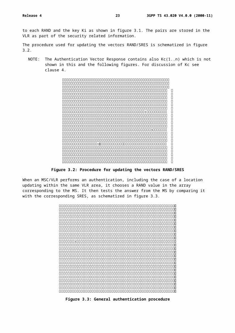
The procedure used for updating the vectors RAND/SRES is schematized in figure 3.2.
NOTE: The Authentication Vector Response contains also Kc(1..n) which is not shown in this and the following figures. For discussion of Kc see clause 4.
3GPP TS 43.020 V4.0.0 (2000-11)19Release 4
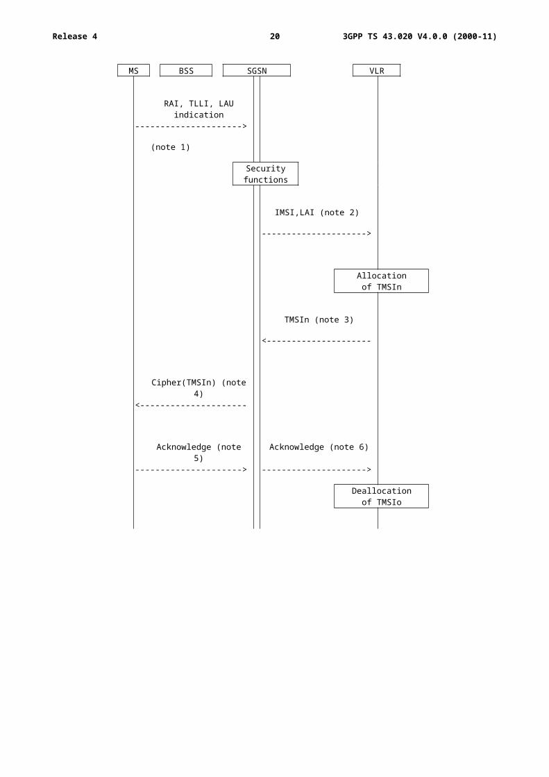
Figure 3.2: Procedure for updating the vectors RAND/SRES
When an MSC/VLR performs an authentication, including the case of a location updating within the same VLR area, it chooses a RAND value in the array corresponding to the MS. It then tests the answer from the MS by comparing it with the corresponding SRES, as schematized in figure 3.3.
Figure 3.3: General authentication procedure
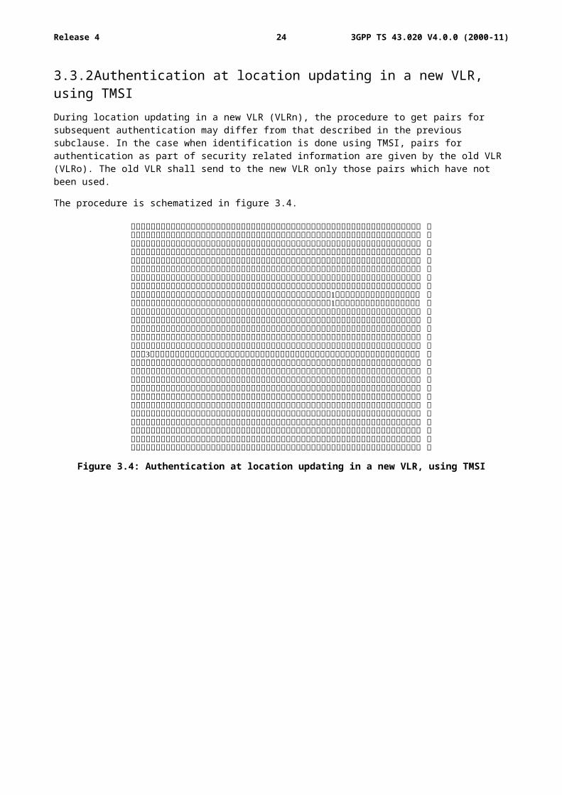
3.3.2 Authentication at location updating in a new VLR, using TMSIDuring location updating in a new VLR (VLRn), the procedure to get pairs for subsequent authentication may differ from that described in the previous subclause. In the case when identification is done using TMSI, pairs for authentication as part of security related information are given by the old VLR (VLRo). The old VLR shall send to the new VLR only those pairs which have not been used.
The procedure is schematized in figure 3.4.
3GPP TS 43.020 V4.0.0 (2000-11)20Release 4
Figure 3.4: Authentication at location updating in a new VLR, using TMSI
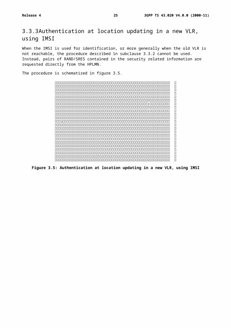
3.3.3 Authentication at location updating in a new VLR, using IMSIWhen the IMSI is used for identification, or more generally when the old VLR is not reachable, the procedure described in subclause 3.3.2 cannot be used. Instead, pairs of RAND/SRES contained in the security related information are requested directly from the HPLMN.
The procedure is schematized in figure 3.5.
Figure 3.5: Authentication at location updating in a new VLR, using IMSI
3GPP TS 43.020 V4.0.0 (2000-11)21Release 4
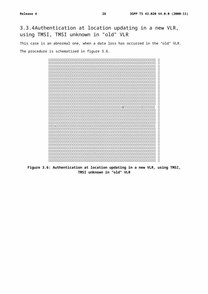
3.3.4 Authentication at location updating in a new VLR, using TMSI, TMSI unknown in "old" VLRThis case is an abnormal one, when a data loss has occurred in the "old" VLR.
The procedure is schematized in figure 3.6.
Figure 3.6: Authentication at location updating in a new VLR, using TMSI,TMSI unknown in "old" VLR
3GPP TS 43.020 V4.0.0 (2000-11)22Release 4
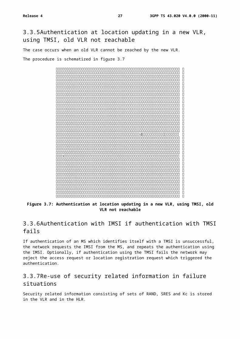
3.3.5 Authentication at location updating in a new VLR, using TMSI, old VLR not reachableThe case occurs when an old VLR cannot be reached by the new VLR.
The procedure is schematized in figure 3.7
Figure 3.7: Authentication at location updating in a new VLR, using TMSI, old VLR not reachable
3.3.6 Authentication with IMSI if authentication with TMSI failsIf authentication of an MS which identifies itself with a TMSI is unsuccessful, the network requests the IMSI from the MS, and repeats the authentication using the IMSI. Optionally, if authentication using the TMSI fails the network may reject the access request or location registration request which triggered the authentication.
3.3.7 Re-use of security related information in failure situationsSecurity related information consisting of sets of RAND, SRES and Kc is stored in the VLR and in the HLR.
When a VLR has used a set of security related information to authenticate an MS, it shall delete the set of security related information or mark it as used. When a VLR needs to use security related information, it shall use a set which is not marked as used in preference to a set which is marked as used; if there are no sets which are not marked as used then the VLR shall request fresh security related information from the HLR. If a set of fresh security related information cannot be obtained in this case because of a system failure, the VLR may re-use a set which is marked as used.
“System failure” in this context means that the VLR was unable to establish contact with the HLR, or the HLR returned a positive acknowledgement containing no sets of security related information, or the HLR returned an error indicating that there was a system failure or that the request was badly formatted.
If the HLR responds to a request for security related information with an indication that the subscriber is unknown or barred in the HLR, the VLR shall not re-use security information which has been marked as used.
3GPP TS 43.020 V4.0.0 (2000-11)23Release 4
It is an operator option to define how many times a set of security related information may be re-used in the VLR; when a set of security related information has been re-used as many times as is permitted by the operator, it shall be deleted.
If a VLR successfully requests security related information from the HLR, it shall discard any security related information which is marked as used in the VLR.
If a VLR receives from another VLR a request for security related information, it shall send only the sets which are not marked as used.
If an HLR receives a request for security related information, it shall send any sets which are not marked as used; those sets shall then be deleted or marked as used. If there are no sets which are not marked as used, the HLR may as an operator option send sets which are marked as used. It is an operator option to define how many times a set of security related information may be re-sent by the HLR; when a set of security related information has been sent as many times as is permitted by the operator, it shall be deleted.
4 Confidentiality of signalling information elements, connectionless data and user information elements on physical connections
4.1 GeneralityIn GSM 02.09, some signalling information elements are considered sensitive and must be protected.
To ensure identity confidentiality (see clause 2), the Temporary Subscriber Identity must be transferred in a protected mode at allocation time and at other times when the signalling procedures permit it.
The confidentiality of connection less user data requires at least the protection of the message part pertaining to OSI layers 4 and above.
The user information confidentiality of user information on physical connections concerns the information transmitted on a traffic channel on the MS-BSS interface (e.g. for speech). It is not an end-to-end confidentiality service.
These needs for a protected mode of transmission are fulfilled with the same mechanism where the confidentiality function is a OSI layer 1 function. The scheme described below assumes that the main part of the signalling information elements is transmitted on DCCH (Dedicated Control Channel), and that the CCCH (Common Control Channel) is only used for the allocation of a DCCH.
Four points have to be specified:
- the ciphering method;
- the key setting;
- the starting of the enciphering and deciphering processes;
- the synchronization.
3GPP TS 43.020 V4.0.0 (2000-11)24Release 4
4.2 The ciphering methodThe layer 1 data flow (transmitted on DCCH or TCH) is ciphered by a bit per bit or stream cipher, i.e. the data flow on the radio path is obtained by the bit per bit binary addition of the user data flow and a ciphering bit stream, generated by algorithm A5 using a key determined as specified in subclause 4.3. The key is denoted below by Kc, and is called "Ciphering Key".
For multislot configurations (e.g. HSCSD) different ciphering bit streams are used on the different timeslots. On timeslot "n" a ciphering bit stream, generated by algorithm A5, using a key Kcn is used. Kcn is derived from Kc as follows:
Let BN denote a binary encoding onto 64 bits of the timeslot number "n" (range 0-7). Bit "i" of Kcn, Kcn(i), is then calculated as Kc(i) xor (BN<<32(i)) ("xor" indicates: "bit per bit binary addition" and "<<32" indicates: "32 bit circular shift"), the number convention being such that the lsb of Kc is xored with the lsb of the shifted BN.
Deciphering is performed by exactly the same method.
Algorithm A5 is specified in annex C.
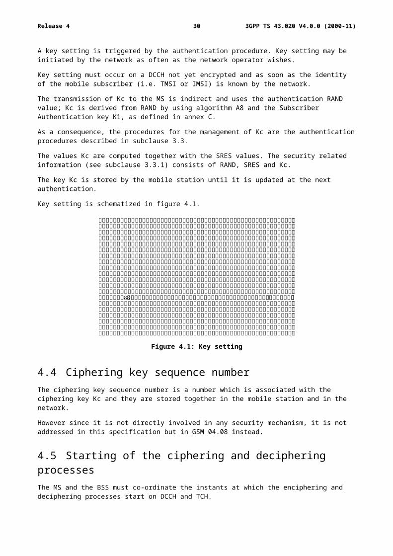
4.3 Key settingMutual key setting is the procedure that allows the mobile station and the network to agree on the key Kc to use in the ciphering and deciphering algorithms A5.
A key setting is triggered by the authentication procedure. Key setting may be initiated by the network as often as the network operator wishes.
Key setting must occur on a DCCH not yet encrypted and as soon as the identity of the mobile subscriber (i.e. TMSI or IMSI) is known by the network.
The transmission of Kc to the MS is indirect and uses the authentication RAND value; Kc is derived from RAND by using algorithm A8 and the Subscriber Authentication key Ki, as defined in annex C.
As a consequence, the procedures for the management of Kc are the authentication procedures described in subclause 3.3.
The values Kc are computed together with the SRES values. The security related information (see subclause 3.3.1) consists of RAND, SRES and Kc.
The key Kc is stored by the mobile station until it is updated at the next authentication.
Key setting is schematized in figure 4.1.
Figure 4.1: Key setting
3GPP TS 43.020 V4.0.0 (2000-11)25Release 4
4.4 Ciphering key sequence numberThe ciphering key sequence number is a number which is associated with the ciphering key Kc and they are stored together in the mobile station and in the network.
However since it is not directly involved in any security mechanism, it is not addressed in this specification but in GSM 04.08 instead.
4.5 Starting of the ciphering and deciphering processesThe MS and the BSS must co-ordinate the instants at which the enciphering and deciphering processes start on DCCH and TCH.
On DCCH, this procedure takes place under the control of the network some time after the completion of the authentication procedure (if any), or after the key Kc has been made available at the BSS.
No information elements for which protection is needed must be sent before the ciphering and deciphering processes are operating.
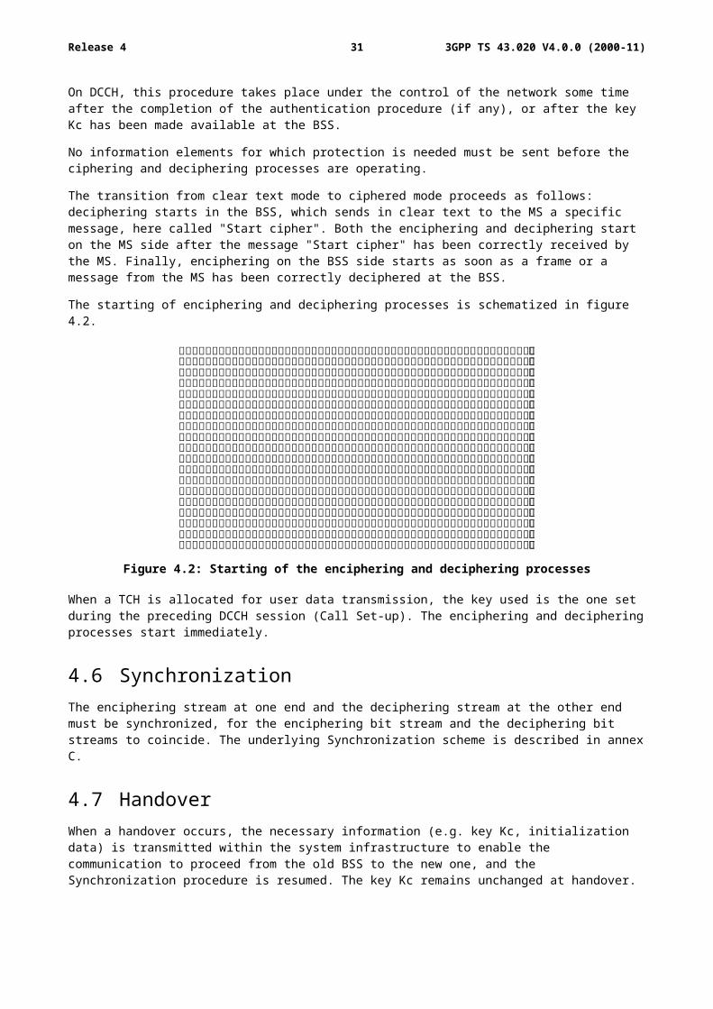
The transition from clear text mode to ciphered mode proceeds as follows: deciphering starts in the BSS, which sends in clear text to the MS a specific message, here called "Start cipher". Both the enciphering and deciphering start on the MS side after the message "Start cipher" has been correctly received by the MS. Finally, enciphering on the BSS side starts as soon as a frame or a message from the MS has been correctly deciphered at the BSS.
The starting of enciphering and deciphering processes is schematized in figure 4.2.
Figure 4.2: Starting of the enciphering and deciphering processes
When a TCH is allocated for user data transmission, the key used is the one set during the preceding DCCH session (Call Set-up). The enciphering and deciphering processes start immediately.
4.6 SynchronizationThe enciphering stream at one end and the deciphering stream at the other end must be synchronized, for the enciphering bit stream and the deciphering bit streams to coincide. The underlying Synchronization scheme is described in annex C.
4.7 HandoverWhen a handover occurs, the necessary information (e.g. key Kc, initialization data) is transmitted within the system infrastructure to enable the communication to proceed from the old BSS to the new one, and the Synchronization procedure is resumed. The key Kc remains unchanged at handover.
3GPP TS 43.020 V4.0.0 (2000-11)26Release 4
4.8 Negotiation of A5 algorithmNot more then seven versions of the A5 algorithm will be defined.
When an MS wishes to establish a connection with the network, the MS shall indicate to the network which of the seven versions of the A5 algorithm it supports. The network shall not provide service to an MS which indicates that it does not support the ciphering algorithm(s) required by GSM 02.07.
The network shall compare its ciphering capabilities and preferences, and any special requirements of the subscription of the MS, with those indicated by the MS and act according to the following rules:
1) If the MS and the network have no versions of the A5 algorithm in common and the network is not prepared to use an unciphered connection, then the connection shall be released.
2) If the MS and the network have at least one version of the A5 algorithm in common, then the network shall select one of the mutually acceptable versions of the A5 algorithm for use on that connection.
3) If the MS and the network have no versions of the A5 algorithm in common and the network is willing to use an unciphered connection, then an unciphered connection shall be used.
3GPP TS 43.020 V4.0.0 (2000-11)27Release 4
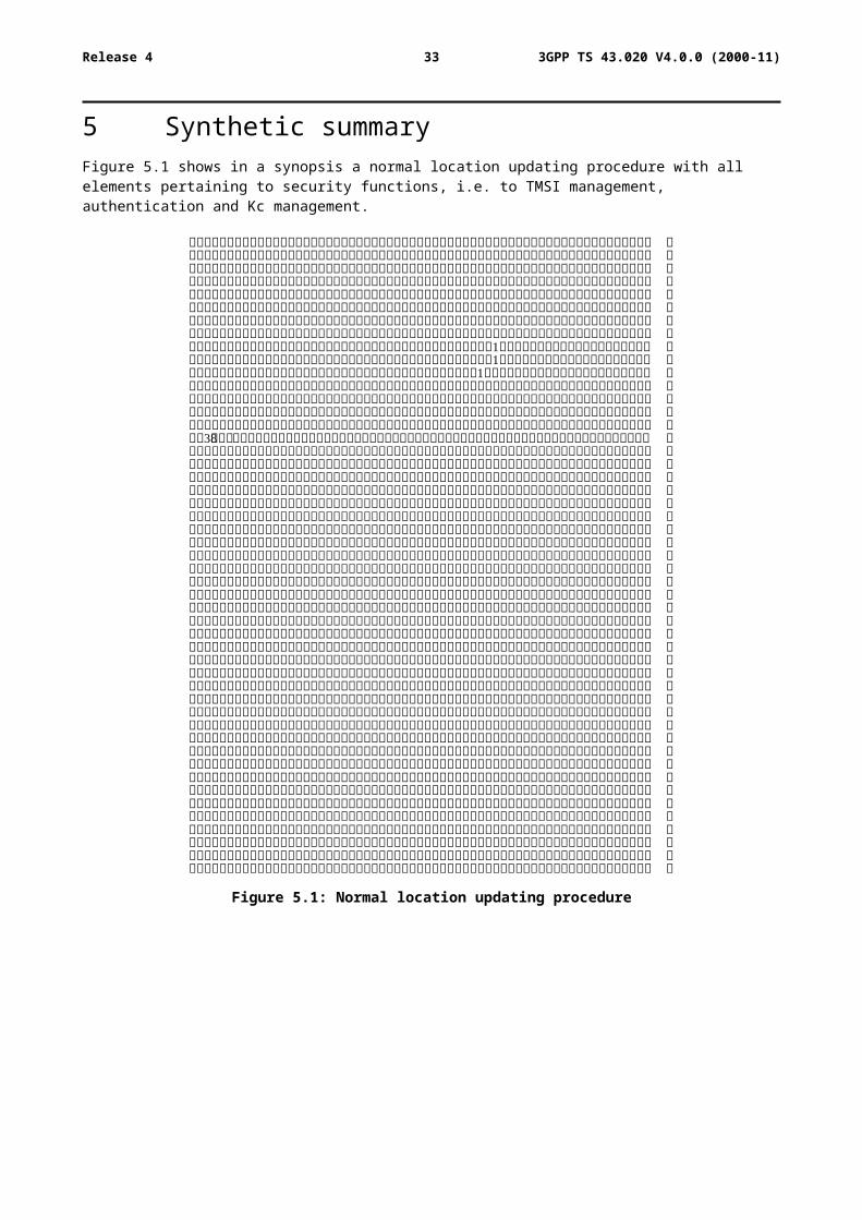
5 Synthetic summaryFigure 5.1 shows in a synopsis a normal location updating procedure with all elements pertaining to security functions, i.e. to TMSI management, authentication and Kc management.
Figure 5.1: Normal location updating procedure
3GPP TS 43.020 V4.0.0 (2000-11)28Release 4
Annex A (informative):Security issues related to signalling schemes and key management
A.1 IntroductionThe diagrams in this annex indicate the security items related to signalling functions and to some of the key management functions. The purpose of the diagrams is to give a general overview of signalling, both on the radio path and in the fixed network. The diagrams indicate how and where keys are generated, distributed, stored and used. The security functions are split between VLR and BSS/MSC.
A.2 Short description of the schemesScheme 1:Location registration
- no TMSI available.
The situation occurs where an MS requests registration and for some reason e.g. TMSI is lost or this is the first registration, there is no TMSI available. In this case the IMSI is used for identification. The IMSI is sent in clear text via the radio path as part of the location updating.
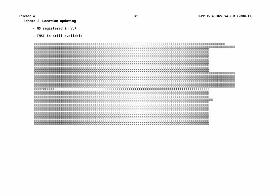
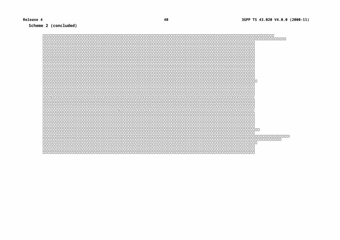
Scheme 2:Location updating
- MS registered in VLR;
- TMSI is still available.
The mobile station stays within the area controlled by the VLR. The mobile station is already registered in this VLR. All information belonging to the mobile station is stored in the VLR, so no connection with the HLR is necessary. Identification is done by the CKSN, LAI and TMSI. For authentication a new set of RAND, SRES and Kc is already available in the VLR.
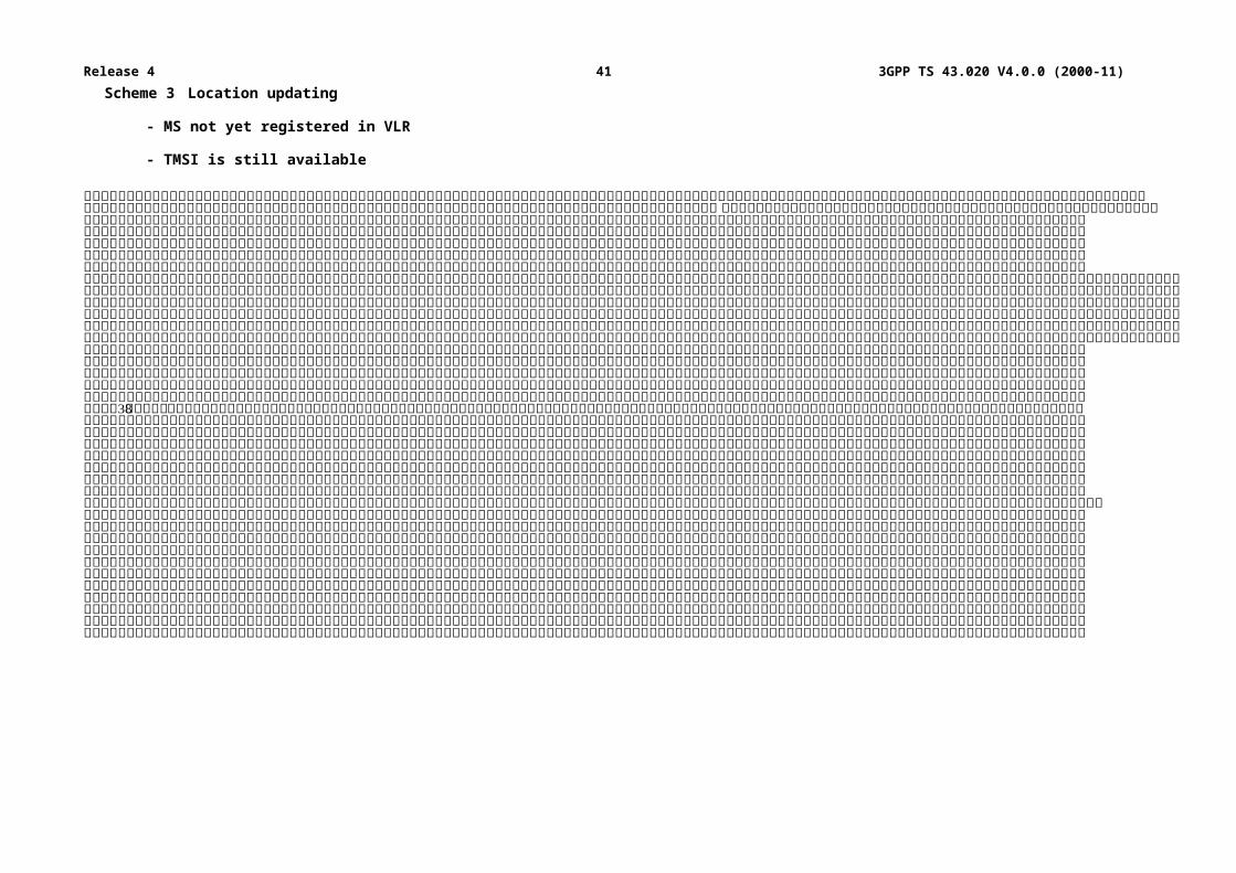
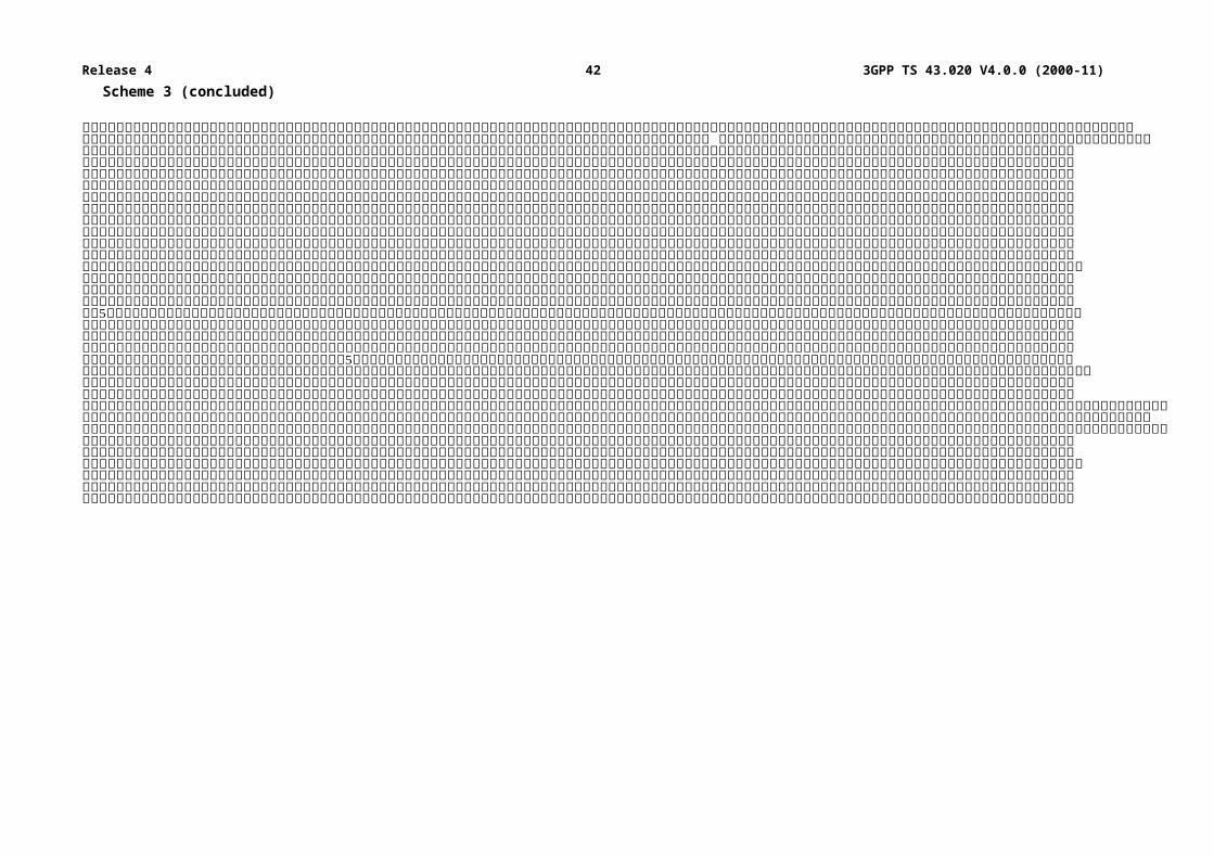
Scheme 3:Location updating
- MS not yet registered in VLR;
- TMSI is still available.
The MS has roamed to an area controlled by another VLR. The LAI is used to address the "old" VLR. The TMSI is used for identification. The "old" VLR informs the "new" VLR about this MS. The security related information is sent by the "old" VLR to the "new" VLR.
Scheme 4:Location updating
- MS not yet registered in VLR and no old LAI.
The VLR cannot identify the VLR where the MS was last registered. Identification is therefore done by using the IMSI. The VLR cannot request authentication information from the previous VLR (LAI not available), so the HLR has to send the authentication information to the VLR.
3GPP TS 43.020 V4.0.0 (2000-11)29Release 4
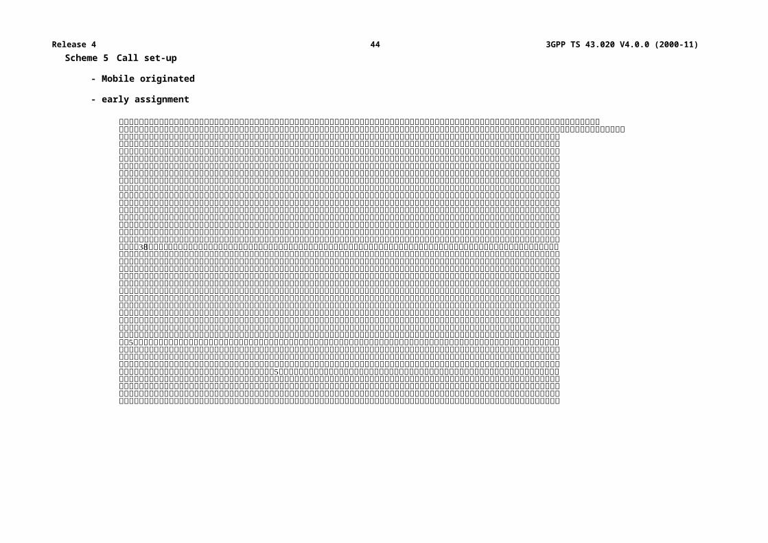
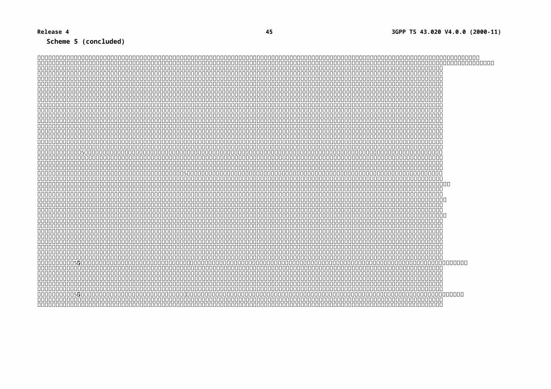
Scheme 5:Call set-up
- mobile originated;
- early assignment.
The users of the registered MS wants to set-up a call. Identification is done by using the TMSI. All signalling information elements in all messages on the radio path are encrypted with ciphering key Kc. The PLMN is setting up calls with "early assignment".
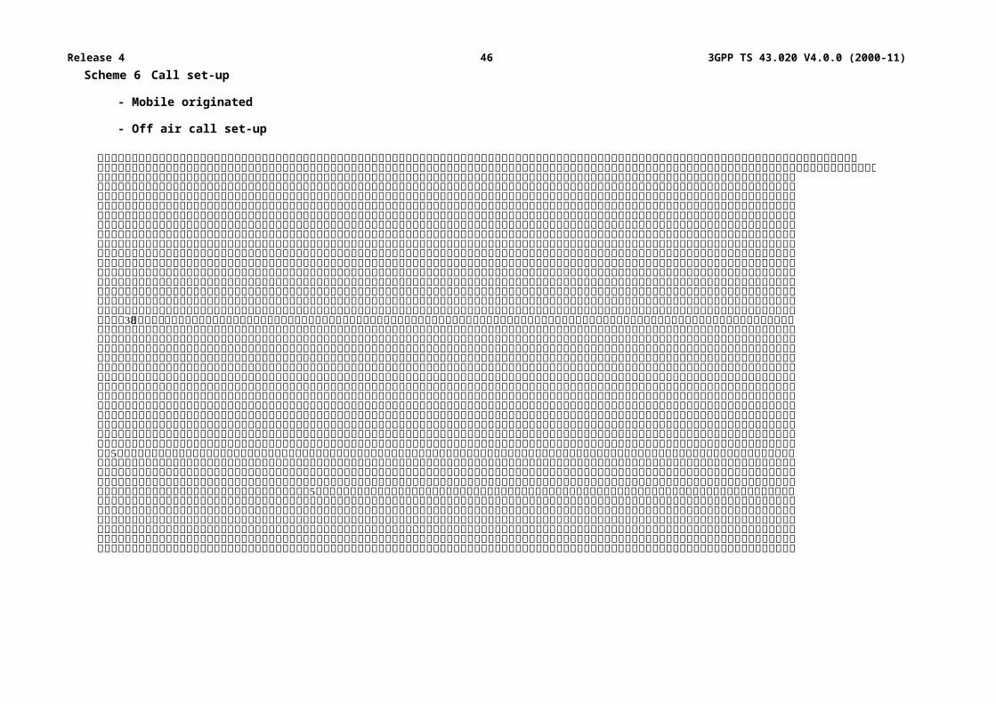
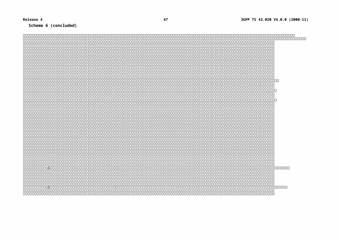
Scheme 6:Call set-up
- mobile originated;
- off air call set-up.
As in scheme 5 the user of the registered MS wants to set-up a call. Identification is done by using the TMSI. All signalling information elements in all messages on the radio path are encrypted with ciphering key Kc after the cipher mode command message. The PLMN is setting up calls with "off air call set-up"
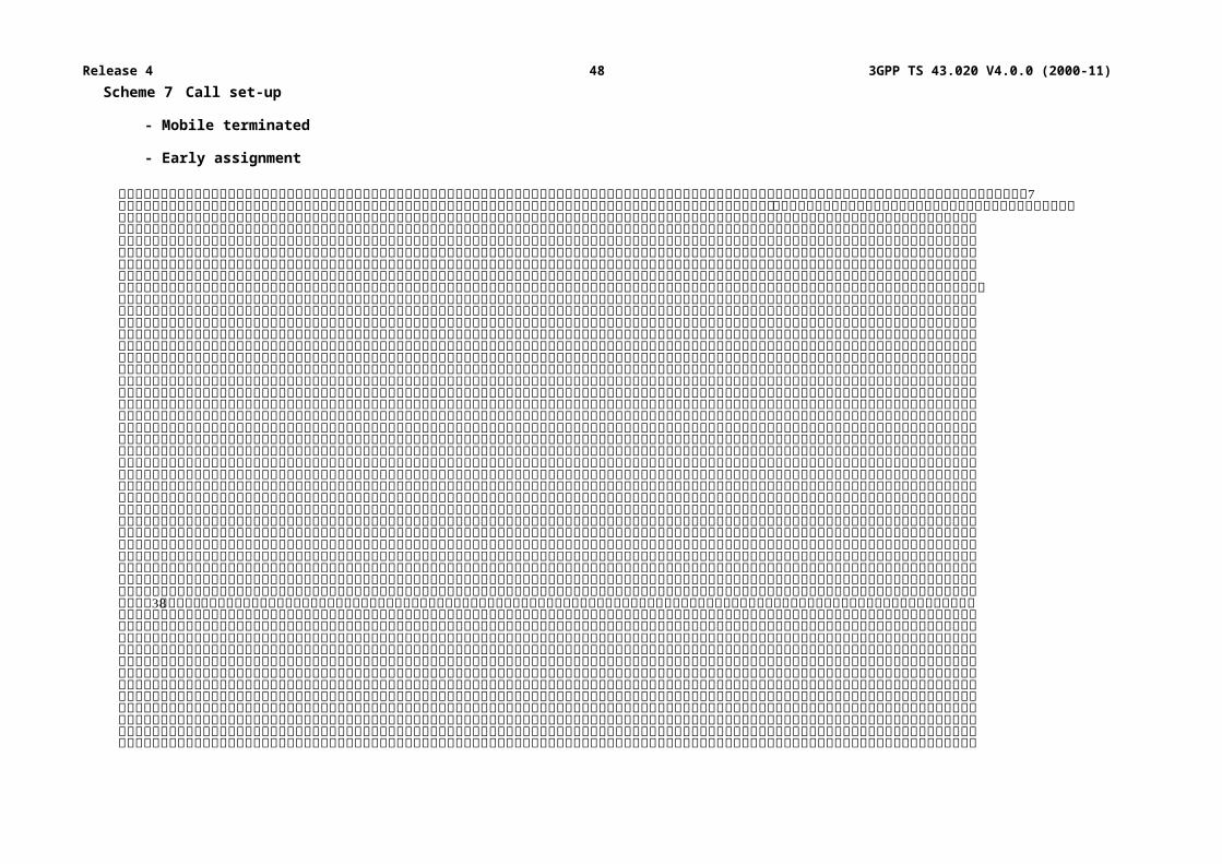
Scheme 7:Call set-up
- mobile terminated;
- early assignment.
A paging request is sent to the registered MS, addressed by the TMSI. All signalling information elements in all messages on the radio path are encrypted with ciphering key Kc after the cipher mode command message. The PLMN is setting up calls with "early assignment".
A.3 List of abbreviationsIn addition to the abbreviations listed in GSM 01.04, the following abbreviations are used in the schemes:
A3 authentication algorithmA5 signalling data and user data encryption algorithmA8 ciphering key generating algorithmBSS Base Station SystemHLR Home Location RegisterIMSI International Mobile Subscriber IdentityKc ciphering keyKc[M] message encrypted with ciphering key KcKc[TMSI] TMSI encrypted with ciphering key KcKi individual subscriber authentication keyLAI Location Area IdentityMS Mobile StationMSC Mobile services Switching CentreR Random number (RAND)S Signed response (SRES)TMSI o/n Temporary Mobile Subscriber Identity old/newVLR o/n Visitor Location Register old/new
3GPP TS 43.020 V4.0.0 (2000-11)30Release 4
Scheme 1 Location registration
- no TMSI available
3GPP TS 43.020 V4.0.0 (2000-11)31Release 4
Scheme 1 (concluded)
3GPP TS 43.020 V4.0.0 (2000-11)32Release 4
Scheme 2 Location updating
- MS registered in VLR
- TMSI is still available
3GPP TS 43.020 V4.0.0 (2000-11)33Release 4
Scheme 2 (concluded)
3GPP TS 43.020 V4.0.0 (2000-11)34Release 4
Scheme 3 Location updating
- MS not yet registered in VLR
- TMSI is still available
3GPP TS 43.020 V4.0.0 (2000-11)35Release 4
Scheme 3 (concluded)
3GPP TS 43.020 V4.0.0 (2000-11)36Release 4
Scheme 4 Location updating
- MS not yet registered in VLR; no old LAI
3GPP TS 43.020 V4.0.0 (2000-11)37Release 4
Scheme 5 Call set-up
- Mobile originated
- early assignment
3GPP TS 43.020 V4.0.0 (2000-11)38Release 4
Scheme 5 (concluded)
3GPP TS 43.020 V4.0.0 (2000-11)39Release 4
Scheme 6 Call set-up
- Mobile originated
- Off air call set-up
3GPP TS 43.020 V4.0.0 (2000-11)40Release 4
Scheme 6 (concluded)
3GPP TS 43.020 V4.0.0 (2000-11)41Release 4
Scheme 7 Call set-up
- Mobile terminated
- Early assignment
3GPP TS 43.020 V4.0.0 (2000-11)42Release 4

Scheme 7 (concluded)
3GPP TS 43.020 V4.0.0 (2000-11)43Release 4
Annex B (informative):Security information to be stored in the entities of the GSM system
B.1 IntroductionThis annex gives an overview of the security related information and the places where this information is stored in the GSM network.
The entities of the GSM network where security information is stored are:
- home location register;
- visitor location register;
- mobile services switching centre;
- base station system;
- mobile station;
- authentication centre.
B.2 Entities and security information
B.2.1 Home Location Register (HLR)If required, sets of Kc, RAND and SRES coupled to each IMSI are stored in the HLR.
B.2.2 Visitor Location Register (VLR)Sets of Kc, RAND and SRES coupled to each IMSI are stored in the VLR. In addition the CKSN, LAI and TMSI are stored together with the presumed valid Kc.
After a new TMSI is generated, both the old and the new TMSI are stored. When the old TMSI is no longer valid, it is removed from the database.
B.2.3 Mobile services Switching Centre (MSC)/Base Station System (BSS)Encryption algorithm A5 is stored in the MSC/BSS.
Call related information stored in the MSC includes the ciphering key Kc and CKSN associated with the identity of the mobile engaged in this call.
After a new TMSI is generated, both the old and the new TMSI are stored. When the old TMSI is no longer valid, it is removed from the database.
3GPP
3GPP TS 43.020 V4.0.0 (2000-11)44Release 4
B.2.4 Mobile Station (MS)The mobile station stores permanently:
- authentication algorithm A3;
- encryption algorithm A5;
- ciphering key generating algorithm A8;
- individual subscriber authentication key Ki;
- ciphering key Kc;
- ciphering key sequence number;
- TMSI.
The mobile station generates and stores:
- ciphering key Kc.
The mobile station receives and stores:
- ciphering key sequence number;
- TMSI;
- LAI.
B.2.5 Authentication Centre (AuC)In the authentication centre are implemented:
- authentication algorithm(s) A3;
- ciphering key generating algorithm(s) A8.
The secret individual authentication keys Ki of each subscriber are stored in an authentication centre.
3GPP
3GPP TS 43.020 V4.0.0 (2000-11)45Release 4
Annex C (normative):External specifications of security related algorithms
C.0 ScopeThis annex specifies the cryptological algorithms which are needed to provide the various security features and mechanisms defined in, respectively, GSM 02.09 and GSM 03.20.
The following three algorithms are considered in GSM 03.20:
- Algorithm A3: Authentication algorithm;
- Algorithm A5: Ciphering/deciphering algorithm;
- Algorithm A8: Ciphering key generator.
Algorithm A5 must be common to all GSM PLMNs and all mobile stations (in particular, to allow roaming). The external specifications of Algorithm A5 are defined in subclause C.1.3. The internal specifications of Algorithm A5 are managed under the responsibility of GSM/MoU; they will be made available in response to an appropriate request.
Algorithms A3 and A8 are at each PLMN operator discretion. Only the formats of their inputs and outputs must be specified. It is also desirable that the processing times of these algorithms remain below a maximum value. Proposals for Algorithm A3 and A8 are managed by GSM/MoU and available, for those PLMN operators who wish to use them, in response to an appropriate request.
C.1 Specifications for Algorithm A5
C.1.1 PurposeAs defined in GSM 03.20, Algorithm A5 realizes the protection of both user data and signalling information elements at the physical layer on the dedicated channels (TCH or DCCH).
Synchronization of both the enciphering and deciphering (especially at hand-over) must be guarantied.
C.1.2 Implementation indicationsAlgorithm A5 is implemented into both the MS and the BSS. On the BSS side description below assumes that one algorithm A5 is implemented for each physical channel (TCH or DCCH).
The ciphering takes place before modulation and after interleaving (see GSM 05.01); the deciphering takes place after demodulation symmetrically. Both enciphering and deciphering need Algorithm A5 and start at different times (see clause 4).
As an indication, recall that, due to the TDMA techniques used in the system, the useful data (also called the plain text in the sequel) are organized into blocks of 114 bits. Then, each block is incorporated into a normal burst (see GSM 05.02) and transmitted during a time slot. According to GSM 05.03, the useful information bits into a block are numbered e0 to e56 and e59 to e115 (the flag bits e57 and e58 are ignored). Successive slots for a given physical channel are separated at least by a frame duration, approximately 4.615 ms (see GSM 05.01).
In the case of EDGE (Enhanced Data rate for GSM Evolution) the useful data are organized into longer blocks than 114 bits. According to GSM 05.03 the useful information in a block is included in 116 symbols which are numbered E(0) to E(115). Each symbol contains 3 bits, hence a block contains 348 useful information bits. See C.1.5 for changes in the usage of the algorithm A5 for EDGE.
3GPP
3GPP TS 43.020 V4.0.0 (2000-11)46Release 4
For ciphering, Algorithm A5 produces, each 4.615 ms, a sequence of 114 encipher/decipher bits (here called BLOCK) which is combined by a bit-wise modulo 2 addition with the 114-bit plain text block. The first encipher/decipher bit produced by A5 is added to e0, the second to e1 and so on. As an indication, the resulting 114-bit block is then applied to the burst builder (see GSM 05.01).
For each slot, deciphering is performed on the MS side with the first block (BLOCK1) of 114 bits produced by A5, and enciphering is performed with the second block (BLOCK2). As a consequence, on the network side BLOCK1 is used for enciphering and BLOCK2 for deciphering. Therefore Algorithm A5 must produce two blocks of 114 bits (i.e. BLOCK1 and BLOCK2) each 4.615 ms.
Synchronization is guarantied by driving Algorithm A5 by an explicit time variable, COUNT, derived from the TDMA frame number. Therefore each 114-bit block produced by A5 depends only on the TDMA frame numbering and the ciphering key Kc.
COUNT is expressed in 22 bits as the concatenation of the binary representation of T1, T3 and T2. It is an input parameter of Algorithm A5. The coding of COUNT is shown in figure C.1.
22 21 20 19 18 17 16 15 14 13 12 11 10 9 8 7 6 5 4 3 2 1
Figure C.1: The coding of COUNT
Binary representation of COUNT. Bit 22 is the most significant bit (msb) and bit 1 the least significant bit (lsb) of COUNT. T1, T3 and T2 are represented in binary. (For definition of T1, T3 and T2, see GSM 05.02).
Figure C.2 summarizes the implementation indications listed above, with only one enciphering/deciphering procedure represented (the second one for deciphering/enciphering is symmetrical).
Figure C.2: Deciphering on the MS side
3GPP
3GPP TS 43.020 V4.0.0 (2000-11)47Release 4
C.1.3 External specifications of Algorithm A5The two input parameters (COUNT and Kc) and the output parameters (BLOCK1 and BLOCK2) of Algorithm A5 shall use the following formats:
- length of Kc: 64 bits;
- length of COUNT: 22 bits;
- length of BLOCK1: 114 bits;
- length of BLOCK2: 114 bits.
Algorithm A5 shall produce BLOCK1 and BLOCK2 in less than a TDMA frame duration, i.e. 4.615 ms.
NOTE: If the actual length of the ciphering key is less than 64 bits, then it is assumed that the actual ciphering key corresponds to the most significant bits of Kc, and that the remaining and less significant bits are set to zero. It must be clear that for signalling and testing purposes the ciphering key Kc is considered to be 64 unstructured bits.
C.1.4 Internal specification of Algorithm A5The internal specification of Algorithm A5 is managed under the responsibility of GSM/MoU; it will be made available to in response to an appropriate request.
C.1.5 A modification of the usage of A5 for EDGEIn EDGE the block size is greater than 114 bits. With EDGE a modification of the usage of the A5 algorithm is employed which produces BLOCK 1 and BLOCK2 which each contain 348 bits. The other parameters are not modified. The modified algorithm produces both blocks during a TDMA frame duration, i.e. 4.615 ms. The blocks are combined by bitwise modulo 2 addition with the plaintext data as explained in C.1.2.
It is possible in EDGE that the plaintext data block for either uplink or downlink is shorter than 348 bits. In this case only the first part of the corresponding output parameter BLOCK is used in the bit-wise adition and the rest of the bits are discarded.
C.2 Algorithm A3Algorithm A3 is considered as a matter for GSM PLMN operators. Therefore, only external specifications are given. However a proposal for a possible Algorithm A3 is managed by GSM/MoU and available upon appropriate request.
C.2.1 PurposeAs defined in GSM 03.20, the purpose of Algorithm A3 is to allow authentication of a mobile subscriber's identity.
To this end, Algorithm A3 must compute an expected response SRES from a random challenge RAND sent by the network. For this computation, Algorithm A3 makes use of the secret authentication key Ki.
3GPP
3GPP TS 43.020 V4.0.0 (2000-11)48Release 4
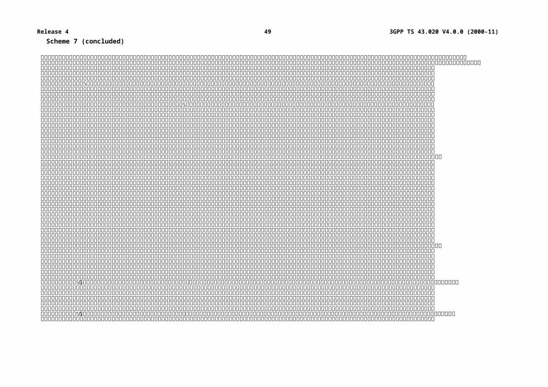
C.2.2 Implementation and operational requirementsOn the MS side, Algorithm A3 is contained in a Subscriber Identity Module, as specified in GSM 02.17.
On the network side, it is implemented in the HLR or the AuC. The two input parameters (RAND and Ki) and the output parameter (SRES) of Algorithm A3 shall use the following formats:
- length of Ki: 128 bits;
- length of RAND: 128 bits;
- length of SRES: 32 bits.
The run-time of Algorithm A3 shall be less than 500 ms.
C.3 Algorithm A8Algorithm A8 is considered as a matter for GSM PLMN operators as is Algorithm A3.
A proposal for a possible Algorithm A8 is managed by GSM/MoU and available upon appropriate request.
C.3.1 PurposeAs defined in GSM 03.20, Algorithm A8 must compute the ciphering key Kc from the random challenge RAND sent during the authentication procedure, using the authentication key Ki.
C.3.2 Implementation and operational requirementsOn the MS side, Algorithm A8 is contained in the SIM, as specified in GSM 02.17.
On the network side, Algorithm A8 is co-located with Algorithm A3.
The two input parameters (RAND and Ki) and the output parameter (Kc) of Algorithm A8 shall follow the following formats:
- length of Ki: 128 bits;
- length of RAND: 128 bits;
- length of Kc: 64 bits.
Since the maximum length of the actual ciphering key is fixed by GSM/MoU, Algorithm A8 shall produce this actual ciphering key and extend it (if necessary) into a 64 bit word where the non-significant bits are forced to zero. It is assumed that any non-significant bits are the least significant bits and that, the actual ciphering key is contained in the most significant bits. For signalling and testing purposes the ciphering key Kc has to considered to be 64 unstructured bits.
3GPP
3GPP TS 43.020 V4.0.0 (2000-11)49Release 4
Annex D (normative):Security related network functions for General Packet Radio ServiceThis annex is only applicable if GPRS is supported.
D.1 GeneralThis annex gives an overview of the different security related services and functions for General Packet Radio Service (GPRS) which is described in GSM 02.60 and GSM 03.60. They are grouped as follows:
- Subscriber identity confidentiality;
- Subscriber identity authentication;
- Confidentiality of user information and signalling between MS and SGSN;
- Security of the GPRS backbone.
It shall be possible to introduce new authentication and ciphering algorithms during the systems lifetime. The fixed part of the network may support more than one authentication and ciphering algorithm.
The security procedures include mechanisms to enable recovery in the event of signalling failures. These recovery procedures are designed to minimise the risk of a breach in the security of the system.
In this annex, the terms GPRS-Kc and GPRS-CKSN are introduced to provide a clear distinction from the ciphering parameters (Kc and CKSN) used for circuit switched. The GPRS-Kc is the ciphering key used for GPRS, and GPRS-CKSN is the corresponding Ciphering Key Sequence Number used for GPRS. The use of these parameters is described in clause D.4.
D.2 Subscriber identity confidentiality
D.2.1 GeneralityThe purpose of this function is to avoid the possibility for an intruder to identify which subscriber is using a given resource on the radio path by listening to the signalling exchanges or the user traffic on the radio path. This allows both a high level of confidentiality for user data and signalling and protection against the tracing of users location.
The provision of this function implies that the IMSI (International Mobile Subscriber Identity), or any information allowing a listener to derive the IMSI easily, should not normally be transmitted in clear text in any signalling message on the radio path.
Consequently, to obtain the required level of protection, it is necessary that:
- a protected identifying method is normally used instead of the IMSI on the radio path;
- the IMSI is not normally used as addressing means on the radio path (see GSM 02.09);
- when the signalling procedures permit it, signalling information elements that convey information about the mobile subscriber identity must be ciphered for transmission on the radio path.
The identifying method is specified in the following subclause. The ciphering of communication over the radio path is specified in clause D.4.
3GPP
3GPP TS 43.020 V4.0.0 (2000-11)50Release 4
Furthermore, Anonymous Access allows a user to access the network without a subscriber identity (see GSM 03.60). Therefore, Anonymous Access always guarantees by its nature subscriber identity confidentiality. The following parts of the clause D.2 are not applicable for Anonymous Access.
D.2.2 Identifying method The means used to identify a mobile subscriber on the radio path consists of a Temporary Logical Link Identity (TLLI). This TLLI is a local number, having a meaning only in a given RA (Routing Area); the TLLI must be accompanied by the Routing Area Identity (RAI) to avoid ambiguities. The maximum length and guidance for defining the format of a TLLI are specified in GSM 03.03.
The SGSN manages suitable data bases to keep the relation between TLLIs and IMSIs. When a TLLI is received with an RAI that does not correspond to the current SGSN, the IMSI of the MS must be requested from the SGSN in charge of the indicated routing area if its address is known; otherwise the IMSI is requested from the MS.
A new TLLI may be allocated in each routing area updating procedure. The allocation of a new TLLI corresponds implicitly for the MS to the de-allocation of the previous one. In the fixed part of the network, the cancellation of the record for an MS in a SGSN implies the de-allocation of the corresponding TLLI.
To cope with some malfunctioning, e.g. arising from a software failure, the fixed part of the network can require the identification of the MS in clear. This procedure is a breach in the provision of the service, and should be used only when necessary.
When a new TLLI is allocated to an MS, it is transmitted to the MS in a ciphered mode. This ciphered mode is the same as defined in clause D.4.
The MS must store its current TLLI in a non volatile memory, together with the RAI, so that these data are not lost when the MS is switched off.
D.2.3 ProceduresThis subclause presents the procedures, or elements of procedures, pertaining to the management of TLLIs.
These security procedures may also be applied between two PLMNs of different operators for seamless service when the PLMN is changed.
D.2.3.1 Routing area updating in the same SGSN areaThis procedure is part of the routing area updating procedure which takes place when the original routing area and the new routing area depend on the same SGSN. The part of this procedure relative to TLLI management is reduced to a TLLI re-allocation (from TLLIo with "o" for "old" to TLLIn with "n" for "new").
The MS sends TLLIo as an identifying field at the beginning of the routing area updating procedure.
The procedure is schematised in figure D.2.1.
MS SGSNRAI, TLLIo
----------------------------------------------------------------------------------->
Allocationof TLLIn
Ciphered(TLLIn)<-----------------------------------------------------------------------------------
Acknowledge----------------------------------------------------------------------------------->
De-allocationof TLLIo
Figure D.2.1: Routing area updating in the same SGSN area
3GPP
3GPP TS 43.020 V4.0.0 (2000-11)51Release 4
D.2.3.2 Routing area updating in a new SGSN; old SGSN reachableThis procedure is part of the routing area updating procedure, using TLLI and RAI, when the original routing area and the new routing area depend on different SGSNs.
The MS is still registered in SGSNo ("o" for old or original) and requests registration in SGSNn ("n" for new). RAI and TLLIo are sent by the MS as identifying fields during the routing area updating procedure. The Routing Area Update Request is not ciphered to allow the new SGSN to read RAI and TLLIo.
The procedure is schematised in figure D.2.2.
MS SGSNn SGSNo HPLMN
RAI, TLLIo RAI,TLLIo---------------------------------------------> ------------------->
IMSI<-------------------
Sec.Rel.Inf
Allocationof TLLIn
Ciphered(TLLIn) (note) Update Loc. (note)<--------------------------------------------- ------------------------------------------>
Acknowledge (note) Acknowledge (note)---------------------------------------------> ------------------------------------------>
Cancellation<-------------------
De-allocationof TLLIo
NOTE: From a security point of view, the order of the procedures is irrelevant.
Figure D.2.2: Routing area updating in a new SGSN; old SGSN reachable
Signalling functionalities:
Update Loc. stands for Update Location
The new SGSN informs the HLR that it is now handling the MS.
Sec.Rel.Info.:
Stands for Security Related information
The SGSNn needs some information for authentication and ciphering; this information is obtained from SGSNo.
Cancellation:
The HLR indicates to SGSNo that the MS is now under control of another SGSN. The "old" TLLI is free for allocation.
3GPP
3GPP TS 43.020 V4.0.0 (2000-11)52Release 4
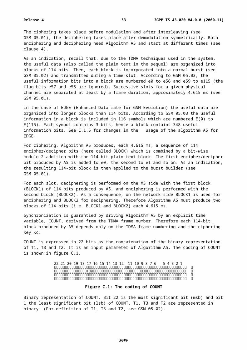
D.2.3.3 Routing area updating in a new SGSN; old SGSN not reachableThis variant of the procedure in subclause D.2.3.2 arises when the SGSN receiving the RAI and TLLIo cannot identify the SGSNo. In that case the relation between TLLIo and IMSI is lost, and the identification of the MS in clear is necessary.
The procedure is schematised in figure D.2.3.
MS SGSNn SGSNo HPLMN
RAI, TLLIo--------------------------------------------->
old SGSN notreachable
TLLI unknown (note 1)<---------------------------------------------
IMSI (note 1)--------------------------------------------->
Management of means for newciphering (see clause D4)
Allocationof TLLIn
Ciphered(TLLIn) (note 2) Update Loc. (note 2)<--------------------------------------------- ------------------------------------------>
Acknowledge (note 2) Acknowledge (note 2)---------------------------------------------> <------------------------------------------
Cancellation<-------------------
De-allocationof TLLIo
NOTE 1: From a security point of view, the exact signalling messages (described in GSM 03.60) used to indicate that the TLLI is unknown, or to send the IMSI are irrelevant.
NOTE 2: From a security point of view, the order of the procedures is irrelevant.
Figure D.2.3: Routing area updating in a new SGSN; old SGSN not reachable
D.2.3.4 Reallocation of a TLLIThis function may be initiated by the network at any time for a GPRS attached MS. The procedure can be included in other procedures, e.g. through the means of optional parameters. The execution of this function is left to the network operator.
When a new TLLI is allocated to an MS the network must prevent the old TLLI from being allocated again until the MS has acknowledged the allocation of the new TLLI.
If an MM context of an MS is deleted in the SGSN by O&M action, the network must prevent any TLLI associated with the deleted MM context from being allocated again until a new TLLI is successfully allocated to that IMSI.
If an IMSI record is deleted in the HLR by O&M action, it is not possible to prevent any TLLI associated with the IMSI record from being allocated again. However, if the MS whose IMSI record was deleted should attempt to access the network using the TLLI after the TLLI has been allocated to a different IMSI, then authentication or ciphering of the MS whose IMSI was deleted will fail, which will cause the TLLI to be deleted from the MS.
The case where allocation of a new TLLI is unsuccessful is described in subclause D.2.3.7.
This procedure is schematised in figure D.2.4.
3GPP
3GPP TS 43.020 V4.0.0 (2000-11)53Release 4
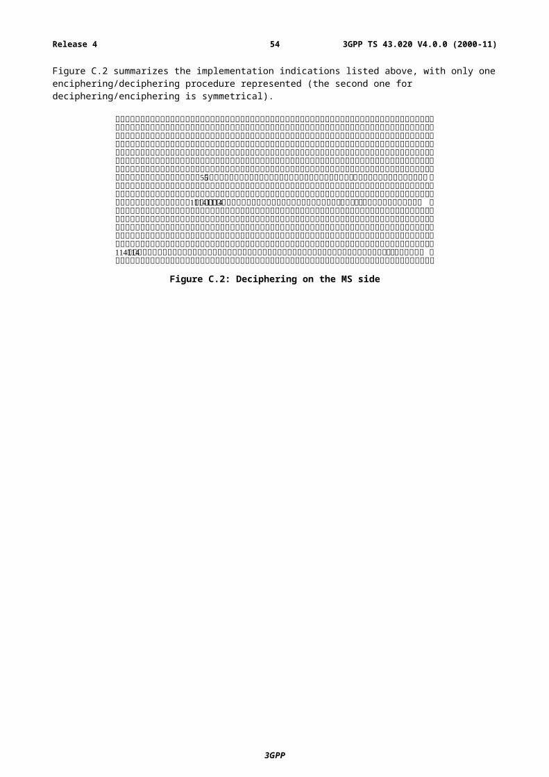
MS SGSN
Allocationof TLLIn
Ciphered(TLLIn)<-----------------------------------------------------------------------------------
Acknowledge----------------------------------------------------------------------------------->
De-allocationof TLLIo
Figure D.2.4: Reallocation of a new TLLI
D.2.3.5 Local TLLI unknownThis procedure is a variant of the procedure described in subclauses D.2.3.1 and happens when a data loss has occurred in a SGSN and when a MS uses an unknown TLLI, e.g. for a communication request or for a routing area updating request in a routing area managed by the same SGSN. The SGSN indicates to the MS that the TLLI is unknown and and the identification of the MS in clear is necessary.
This procedure is schematised in figure D.2.5.
MS SGSN HPLMN
RAI, TLLIo (note 1)-------------------------------------------------------------->
TLLIo isunknown
TLLI unknown (note 2)<--------------------------------------------------------------
IMSI (note 2)-------------------------------------------------------------->
Management of means for newciphering (see clause D4)
Allocationof TLLIn
Ciphered(TLLIn)<--------------------------------------------------------------
Acknowledge-------------------------------------------------------------->
NOTE 1: Any message in which TLLIo is used as an identifying means in a routing area managed by the same SGSN.
NOTE 2: From a security point of view, the exact signalling messages (described in GSM 03.60) used to indicate that the TLLI is unknown, or to send the IMSI are irrelevant.
Figure D.2.5: Routing area updating in the same SGSN area; local TLLI unknown
3GPP
3GPP TS 43.020 V4.0.0 (2000-11)54Release 4
D.2.3.6 Routing area updating in a new SGSN in case of a loss of informationThis variant of the procedure described in D.2.3.2 arises when the SGSN in charge of the MS has suffered a loss of data. In that case the relation between TLLIo and IMSI is lost, and the identification of the MS in clear is necessary.
The procedure is schematised in figure D.2.6.
MS SGSNn SGSNo HPLMN
RAI, TLLIo RAI,TLLIo---------------------------------------------> ------------------->
UnknownTLLI Unknown(note 1) <-------------------
<---------------------------------------------
IMSI(note 1)--------------------------------------------->
Management of means for newciphering (see clause D4)
Allocationof TLLIn
Ciphered(TLLIn) (note 2) Update location (note 2)<--------------------------------------------- ------------------------------------------>
Acknowledge (note 2) Acknowledge (note 2)---------------------------------------------> <------------------------------------------
Cancellation<-------------------
De-allocationof TLLIo
NOTE 1: From a security point of view, the exact signalling messages (described in GSM 03.60) used to indicate that the TLLI is unknown, or to send the IMSI are irrelevant.
NOTE 2: From a security point of view, the order of the procedures is irrelevant.
Figure D.2.6: Routing area updating in a new SGSN in case of a loss of information
D.2.3.7 Unsuccessful TLLI allocationIf the MS does not acknowledge the allocation of a new TLLI, the network shall maintain the association between the old TLLI and the IMSI and between the new TLLI and the IMSI.
For an MS-originated transaction, the network shall allow the MS to identify itself by either the old TLLI or the new TLLI. This will allow the network to determine the TLLI stored in the MS; the association between the other TLLI and the IMSI shall then be deleted.
For a network-originated transaction, the network shall identify the MS by its IMSI. When radio contact has been established, the network shall instruct the MS to delete any stored TLLI. When the MS has acknowledged this instruction, the network shall delete the association between the IMSI of the MS and any TLLI.
In either of the cases above, the network may initiate the normal TLLI reallocation procedure.
Repeated failure of TLLI reallocation (passing a limit set by the operator) may be reported for O&M action.
3GPP
3GPP TS 43.020 V4.0.0 (2000-11)55Release 4
D.3 Subscriber identity authentication
D.3.1 GeneralityThe definition and operational requirements of subscriber identity authentication are given in GSM 02.09.
The authentication procedure may be performed at any time by the network.
The authentication procedure will also be used to set the ciphering key (see clause D.4). Therefore, it is performed after the subscriber identity (TLLI/IMSI) is known by the network for the management of new ciphering.
Two network functions are necessary: the authentication procedure itself, and the key management.
D.3.2 The authentication procedureThe authentication procedure is described in subclause 3.2.
D.3.3 Subscriber Authentication Key managementThe management of Subscriber Authentication Key (Ki) is described in subclause 3.3.
D.3.3.1 General authentication procedureWhen needed, the SGSN requests security related information for a MS from the HLR/AuC corresponding to the IMSI of the MS. This includes an array of pairs of corresponding RAND and SRES. These pairs are obtained by applying Algorithm A3 to each RAND and the key Ki as shown in figure 3.1. The pairs are stored in the SGSN as part of the security related information.
The procedure used for updating the vectors RAND/SRES is schematised in figure D.3.2.
NOTE: The Authentication Vector Response contains also GPRS-Kc(1..n) which is not shown in this and the following figures. For discussion of GPRS-Kc see clause D.4.
SGSN HLR/AuC
Security Related Information Req(IMSI)--------------------------------------------------------------------------------->
generateRAND(1..n)
Ki
V VA3
Authentication Vector Response< ---------------------------------------------------------------------------------
(SRES(1..n), RAND(1..n))
Store RAND/SRESvectors
Figure D.3.2: Procedure for updating the vectors RAND/SRES
3GPP
3GPP TS 43.020 V4.0.0 (2000-11)56Release 4

When an SGSN performs an authentication, including the case of a routing area updating within the same SGSN area, it chooses a RAND value in the array corresponding to the MS. It then tests the answer from the MS by comparing it with the corresponding SRES, as schematised in figure D.3.3.
MS SGSN
RAND(j) SRES(j)<-------------------------------------------------------------------------
Ki RAND(j)V V
A3SRES(j)
V
SRES(j)---------------------------------------------------------------------------> ---------
V V=
Vyes/no
Figure D.3.3: General authentication procedure
D.3.3.2 Authentication at routing area updating in a new SGSN, using TLLIDuring routing area updating in a new SGSN (SGSNn), the procedure to get pairs for subsequent authentication may differ from that described in the previous subclause. In the case when identification is done using TLLI, pairs for authentication as part of security related information are given by the old SGSN (SGSNo). The old SGSN shall send to the new SGSN only those pairs which have not been used. SGSNn may also request the triplets directly from HLR.
The procedure is schematised in figure D.3.4.
MS SGSNn SGSNo HPLMN
RAI, TLLIo TLLIo, RAI------------------------------------> ----------------------------->
IMSIKi RAND(1..n)
SRES(1..n)RAND <-----------------------------
<------------------------------------
V VA3
SRES---------------------------------------->
=
Vyes/no
Update Location
Figure D.3.4: Authentication at routing area updating in a new SGSN, using TLLI
3GPP
3GPP TS 43.020 V4.0.0 (2000-11)57Release 4
D.3.3.3 Authentication at routing area updating in a new SGSN, using IMSIWhen the IMSI is used for identification, or more generally when the old SGSN is not reachable, the procedure described in subclause D.3.3.2 cannot be used. Instead, pairs of RAND/SRES contained in the security related information are requested directly from the HPLMN.
The procedure is schematised in figure D.3.5.
MS SGSNn HPLMN
IMSI Sec. Rel. Info Req.------------------------------------> ------------------------------------------------>
(IMSI)
RAND(1,..n)Ki RAND <------------------------------------------------
<------------------------------------ SRES(1..n)
V VA3
SRES---------------------------------------->
=
Vyes/no
Update Location
Figure D.3.5: Authentication at routing area updating in a new SGSN, using IMSI
3GPP
3GPP TS 43.020 V4.0.0 (2000-11)58Release 4
D.3.3.4 Authentication at routing area updating in a new SGSN, using TLLI, TLLI unknown in 'old' SGSNThis case is an abnormal one, when a data loss has occurred in the 'old' SGSN.
The procedure is schematised in figure D.3.6.
MS SGSNn SGSNo HPLMN
RAI, TLLIo RAI, TLLIo------------------------------------> ----------------------------->
UnknownTLLI Unknown <-----------------------------
<------------------------------------
IMSI------------------------------------> Sec. Rel. Info Req.
------------------------------------------------>(IMSI)
RAND(1..n) SRES(1..n)<------------------------------------------------
RAND<------------------------------------
Ki
V VA3
SRES---------------------------------------->
=
Vyes/no
Update Location
Figure D.3.6: Authentication at routing area updating in a new SGSN, using TLLI, TLLI unknown in 'old' SGSN
3GPP
3GPP TS 43.020 V4.0.0 (2000-11)59Release 4
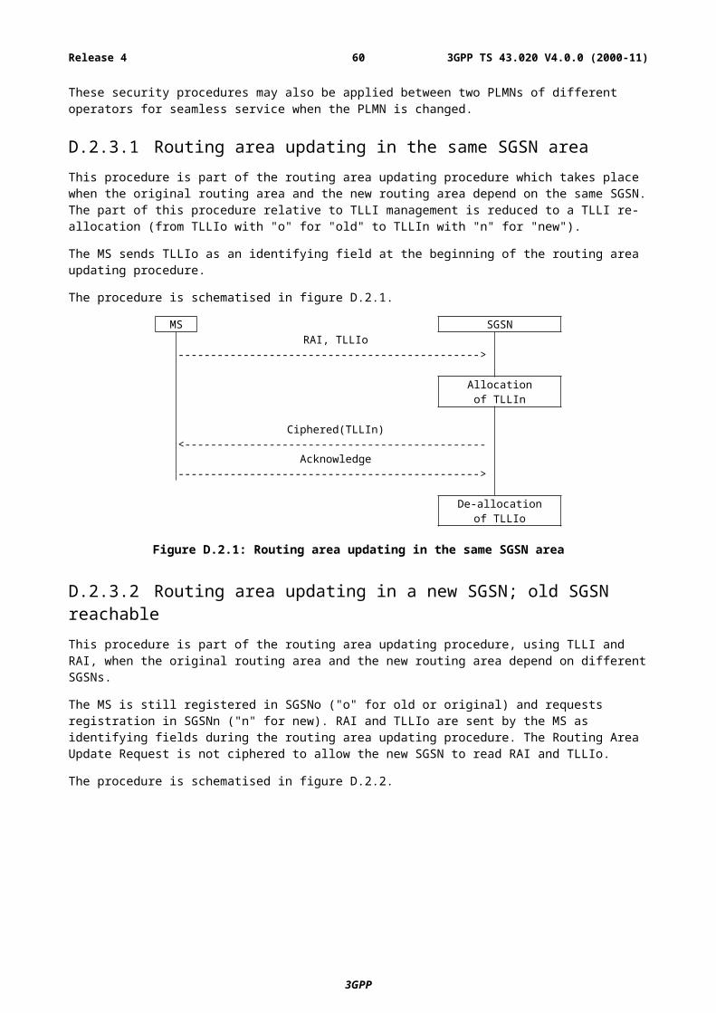
D.3.3.5 Authentication at routing area updating in a new SGSN, using TLLI, old SGSN not reachableThe case occurs when an old SGSN cannot be reached by the new SGSN.
The procedure is schematised in figure D.3.7
MS SGSNn SGSNo HPLMN
RAI, TLLIo------------------------------------>
SGSNo notreachable
TLLI Unknown <-----------------------------<------------------------------------
IMSI------------------------------------> Sec. Rel. Info Req.
------------------------------------------------>(IMSI)
RAND(1..n) SRES(1..n)<------------------------------------------------
RAND<------------------------------------
Ki
V VA3
SRES---------------------------------------->
=
Vyes/no
Update Location
Figure D.3.7: Authentication at routing area updating in a new SGSN, using TLLI, old SGSN not reachable
D.3.3.6 Authentication with IMSI if authentication with TLLI failsIf authentication of an MS which identifies itself with a TLLI is unsuccessful, the network requests the IMSI from the MS, and repeats the authentication using the IMSI. Optionally, if authentication using the TLLI fails the network may reject the access request or location registration request which triggered the authentication.
D.3.3.7 Re-use of security related information in failure situationsSecurity related information consisting of sets of RAND, SRES and a ciphering key (GPRS-Kc) is stored in the SGSN and in the HLR.
When a SGSN has used a set of security related information to authenticate an MS, it shall delete the set of security related information or mark it as used. When a SGSN needs to use security related information, it shall use a set which is not marked as used in preference to a set which is marked as used; if there are no sets which are not marked as used then the SGSN shall request fresh security related information from the HLR. If a set of fresh security related information cannot be obtained in this case because of a system failure, the SGSN may re-use a set which is marked as used.
“System failure” in this context means that the SGSN was unable to establish contact with the HLR, or the HLR returned a positive acknowledgement containing no sets of security related information, or the HLR returned an error indicating that there was a system failure or that the request was badly formatted.
3GPP
3GPP TS 43.020 V4.0.0 (2000-11)60Release 4
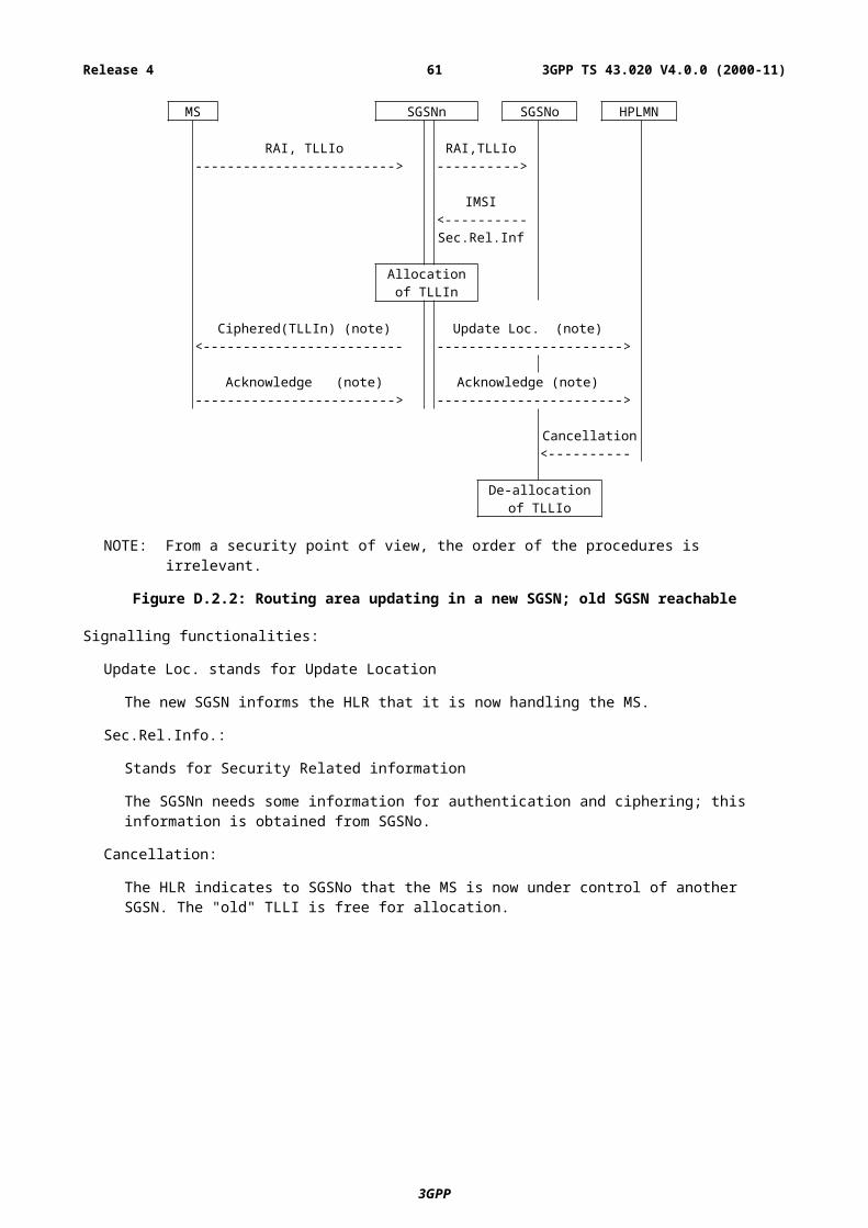
If the HLR responds to a request for security related information with an indication that the subscriber is unknown or barred in the HLR, the SGSN shall not re-use security information which has been marked as used.
It is an operator option to define how many times a set of security related information may be re-used in the SGSN; when a set of security related information has been re-used as many times as is permitted by the operator, it shall be deleted.
If a SGSN successfully requests security related information from the HLR, it shall discard any security related information which is marked as used in the SGSN.
If a SGSN receives from another SGSN a request for security related information, it shall send only the sets which are not marked as used.
If an HLR receives a request for security related information, it shall send any sets which are not marked as used; those sets shall then be deleted or marked as used. If there are no sets which are not marked as used, the HLR may as an operator option send sets which are marked as used. It is an operator option to define how many times a set of security related information may be re-sent by the HLR; when a set of security related information has been sent as many times as is permitted by the operator, it shall be deleted.
D.4 Confidentiality of user information and signalling between MS and SGSN
D.4.1 GeneralityIn GSM 02.09, some signalling information elements are considered sensitive and must be protected.
To ensure identity confidentiality (see clause 2), the new TLLI must be transferred in a protected mode at allocation time.
The confidentiality of user information concerns the information transmitted on the logical connection between MS and SGSN.
These needs for a protected mode of transmission are fulfilled by a ciphering function in the LLC layer. It is not an end-to-end confidentiality service.
Four points have to be specified:
- the ciphering method;
- the key setting;
- the starting of the enciphering and deciphering processes;
- the synchronisation.
D.4.2 The ciphering methodThe LLC layer information flow is ciphered by the algorithm GPRS-A5 as described in GSM 01.61.
3GPP
3GPP TS 43.020 V4.0.0 (2000-11)61Release 4
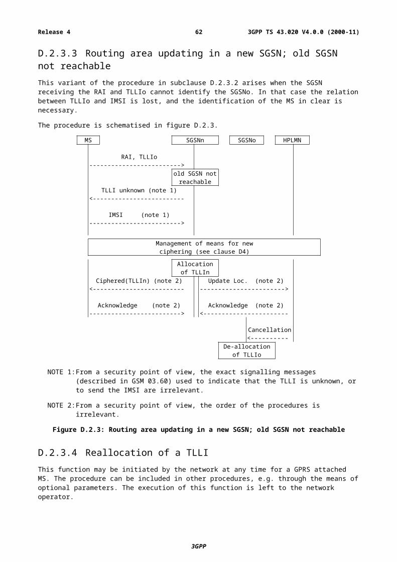
D.4.3 Key settingMutual key setting is the procedure that allows the mobile station and the network to agree on the key GPRS-Kc to use in the ciphering and deciphering algorithms GPRS-A5. This procedure corresponds to the procedure described in subclause 4.3 besides the different confidential subscriber identity. The GPRS-Kc is handled by the SGSN independently from the MSC. If a MS is using both circuit switched and packet switched, two different ciphering keys will be used independently, one (Kc) in the MSC and one (GPRS-Kc) in the SGSN.
A key setting is triggered by the authentication procedure. Key setting may be initiated by the network as often as the network operator wishes. If an authentication procedure is performed during a data transfer, the new ciphering parameters shall be taken in use immediately at the end of the authentication procedure in both SGSN and MS.
Key setting may not be encrypted and shall be performed as soon as the identity of the mobile subscriber (i.e. TLLI or IMSI) is known by the network.
The transmission of GPRS-Kc to the MS is indirect and uses the authentication RAND value; GPRS-Kc is derived from RAND by using algorithm A8 and the Subscriber Authentication key Ki, in the same way as defined in annex C for Kc.
As a consequence, the procedures for the management of GPRS-Kc are the authentication procedures described in subclause D.3.3.
The values GPRS-Kc are computed together with the SRES values. The security related information (see subclause D.3.3.1) consists of RAND, SRES and GPRS-Kc.
The key GPRS-Kc is stored by the mobile station until it is updated at the next authentication.
Key setting is schematised in figure D.4.1.
MS Network side
RAI and TLLI or IMSI------------------------------------------------------------>
RAND<------------------------------------------------------------
Ki RAND RAND KiV V V V
A8 A8
GPRS-Kc GPRS-KcV V
Store GPRS-Kc Store GPRS-Kc
Figure D.4.1: Key setting
D.4.4 Ciphering key sequence numberThe GPRS-CKSN (Ciphering Key Sequence Number) is a number which is associated with each ciphering key GPRS-Kc. The GPRS-CKSN and GPRS-Kc are stored together in the mobile station and in the network. It permits the consistency check of the keys stored in the MS and in the network. Two independent pairs, Kc and CKSN (for circuit switched), and GPRS-Kc and GPRS-CKSN (for packet switched) may be stored in the MS simultaneously.
However since it is not directly involved in any security mechanism, it is not addressed in this specification but in GSM 04.08 instead.
3GPP
3GPP TS 43.020 V4.0.0 (2000-11)62Release 4
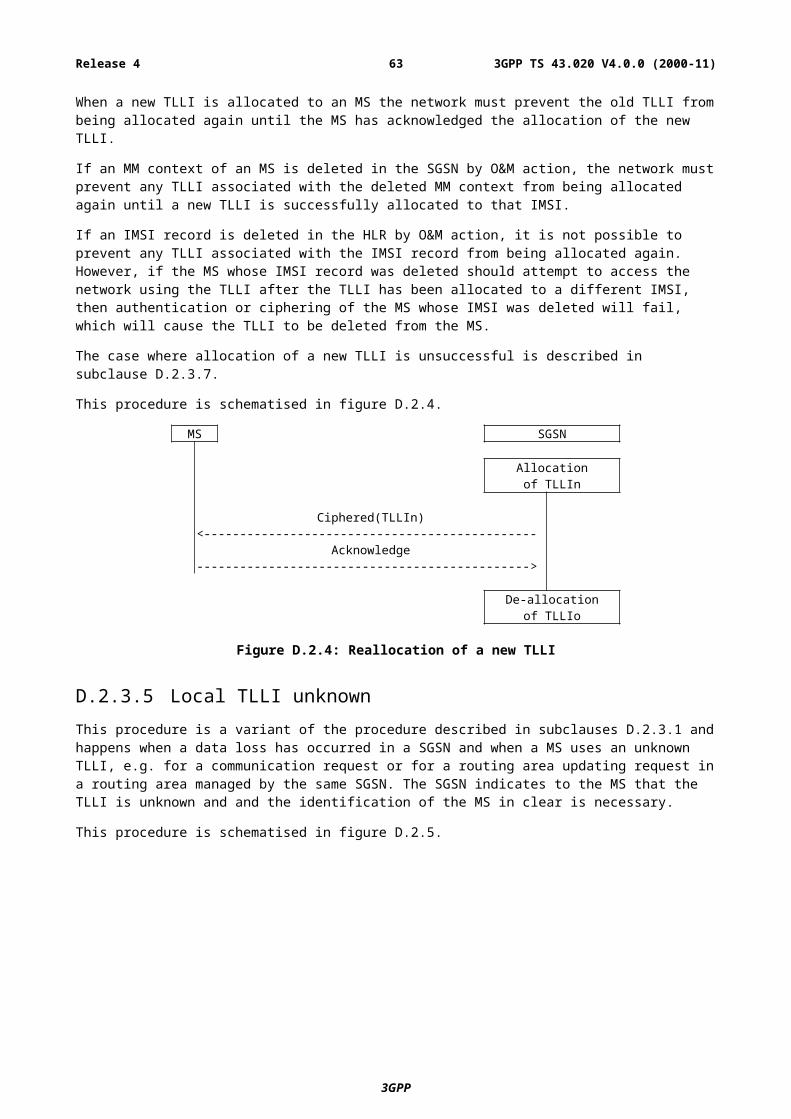
D.4.5 Starting of the ciphering and deciphering processesThe MS and the SGSN must co-ordinate the instants at which the ciphering and deciphering processes start. The authentication procedure governs the start of ciphering. The SGSN indicates if ciphering shall be used or not in the Authentication and Ciphering Request message. If ciphering is used, the MS starts ciphering after sending the Authentication and Ciphering Response message. The SGSN starts ciphering when a valid Authentication and Ciphering Response message is received from the MS.
Upon GPRS Attach, if ciphering is to be used, an Authentication and Ciphering Request message shall be sent to the MS to start ciphering.
If the GPRS-CKSN stored in the network does not match the GPRS-CKSN received from the MS in the Attach Request message, then the network should authenticate the MS.
As an option, the network may decide to continue ciphering without authentication after receiving a Routing Area Update Request message with a valid GPRS-CKSN. Both the MS and the network shall use the latest ciphering parameters. The MS starts ciphering after a receiving a valid ciphered Routing Area Update Accept message from the network. The SGSN starts ciphering when sending the ciphered Routing Area Update Accept message to the MS.
Upon delivery of the Authentication and Ciphering Response message or the Routing Area Update Accept message, the GPRS Mobility and Management entity in both SGSN and MS shall be aware if ciphering has started or not. LLC provides the capability to send both ciphered and unciphered PDUs. The synchronisation of ciphering at LLC frames level is done by a bit in the LLC header indicating if the frame is ciphered or not. Only a few identified signalling messages (e.g., Routing Area Update Request message) described in GSM 04.08 may be sent unciphered, any other frames sent unciphered shall be deleted. Once the encryption has been started, neither the MS nor the network shall go to an unciphered session.
D.4.6 SynchronisationThe enciphering stream at one end and the deciphering stream at the other end must be synchronised, for the enciphering bit stream and the deciphering bit streams to coincide. Synchronisation is guaranteed by driving Algorithm GPRS-A5 by an explicit variable INPUT per established LLC and direction.
These initial INPUT values shall not be identical for the different LLC link. The initial INPUT value shall be determined by the network. It may be identical for uplink and downlink value because the direction is given to the ciphering algorithm as described in GSM 01.61 and illustrated on the figure D.4.2. In a given direction, the INPUT value shall be unique for each frame.
The calculation of the INPUT value is described in GSM. The use of the INPUT value is described in GSM 01.61 and illustrated on the figure D.4.2.
IN PUT DIR ECTIO N
Kc C IPH ERALG O R ITHM
Kc CIPHERALG O RITH M
PLAIN TEXT PLAIN TEXTC IPHERED TEXT CIPH ERED TEXT
SG SN /M S M S/SG SN
O U TPU T O U TPU T
IN PU T D IREC TIO N
Figure D.4.2: Use of the INPUT parameter
3GPP
3GPP TS 43.020 V4.0.0 (2000-11)63Release 4
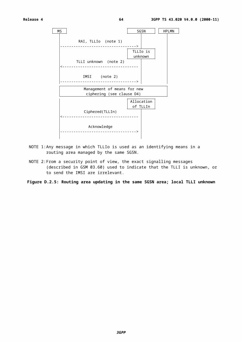
D.4.7 Inter SGSN routing area updateWhen an Inter SGSN routing area update occurs, the necessary information (e.g. key Kc, INPUT parameters) is transmitted within the system infrastructure to enable the communication to proceed from the old SGSN to the new one, and the Synchronisation procedure is resumed. The key Kc may remains unchanged at Inter SGSN routing area update.
D.4.8 Negotiation of GPRS-A5 algorithmNot more than seven versions of the GPRS-A5 algorithm will be defined.
When an MS wishes to establish a connection with the network, the MS shall indicate to the network which version(s) of the GPRS-A5 algorithm it supports. The negotiation of GPRS-A5 algorithm happens during the authentication procedure.
The network may renegotiate the version of the GPRS-A5 algorithm in use at inter SGSN routing area update by performing an authentication procedure.
The network shall compare its ciphering capabilities and preferences, and any special requirements of the subscription of the MS, with those indicated by the MS and may take one of the following decisions:
1) If the MS and the network have no versions of the GPRS A5 algorithm in common and the network is not prepared to use an unciphered connections, then the connection is released.
2) If the MS and the network have at least one version of the GPRS A5 algorithm in common, then the network shall select one of the mutually acceptable versions of the GPRS A5 algorithms for use on that connection.
3) If the MS and the network have no versions of the GPRS A5 algorithm in common and the network is willing to use an unciphered version, then an unciphered connection shall be used.
3GPP
3GPP TS 43.020 V4.0.0 (2000-11)64Release 4
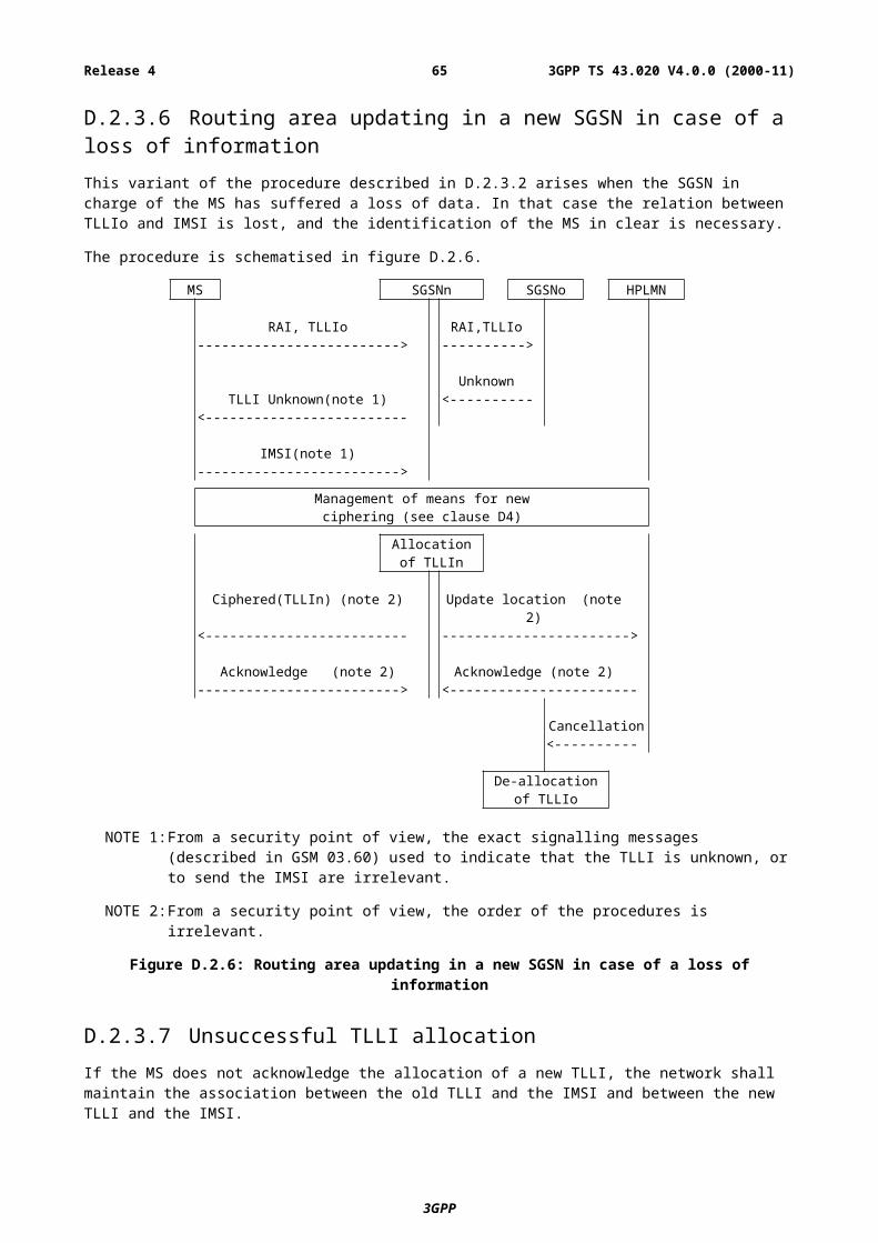
D.5 Synthetic summaryFigure D.5.1 shows in a synopsis a routing area updating procedure with all elements pertaining to security functions, i.e. to TLLI management, authentication and GPRS-Kc management.
MS SGSNn SGSNo HPLMN
RAI, TLLIo RAI, TLLIo------------------------------------> ----------------------------->
Routing area updatingIMSIRANDSRESGPRS-Kc
Ki RAND <-----------------------------<------------------------------------
V VA3&A8
SRES--------------------------------->
V =GPRS-Kc
Vyes
start of cipheringUpdate location
------------------------------------------------>
Acknowledge<------------------------------------------------
Allocationof TLLIn
Routing area update Accept<---------------------------------
TLLI acknowledge--------------------------------->
Cancellation<-----------------
De-allocationof TLLIo
Figure D.5.1: Routing area updating procedure
D.6 Security of the GPRS backboneThe operator is responsible for the security of its own Intra-PLMN backbone which includes all network elements and physical connections. The operator shall prevent unauthorised access to its Intra-PLMN backbone. A secure Intra-PLMN backbone guarantees that no intruder can eavesdrop or modify user information and signalling in the Intra-PLMN backbone.
The GPRS architecture utilises GPRS tunnelling and private IP addressing within the backbone to restrict unauthorised access to the backbone. User traffic addressed to a network element shall be discarded. Firewall functionality may provide these means at the access points (Gi reference point and Gp interface) of the Intra-PLMN backbone.
The Inter-PLMN links shall be negotiated between operators as part of the roaming agreement. They shall ensure that the Inter-PLMN links are secure providing integrity and confidentiality. For example, secure links can be achieved by point to point links, private Inter-PLMN backbones or encrypted tunnels over the public Internet.
Operators shall be able to determine the origin of packets coming from the inter-PLMN backbone. One example is to use a Frame Relay PVC between two operators.
3GPP
3GPP TS 43.020 V4.0.0 (2000-11)65Release 4
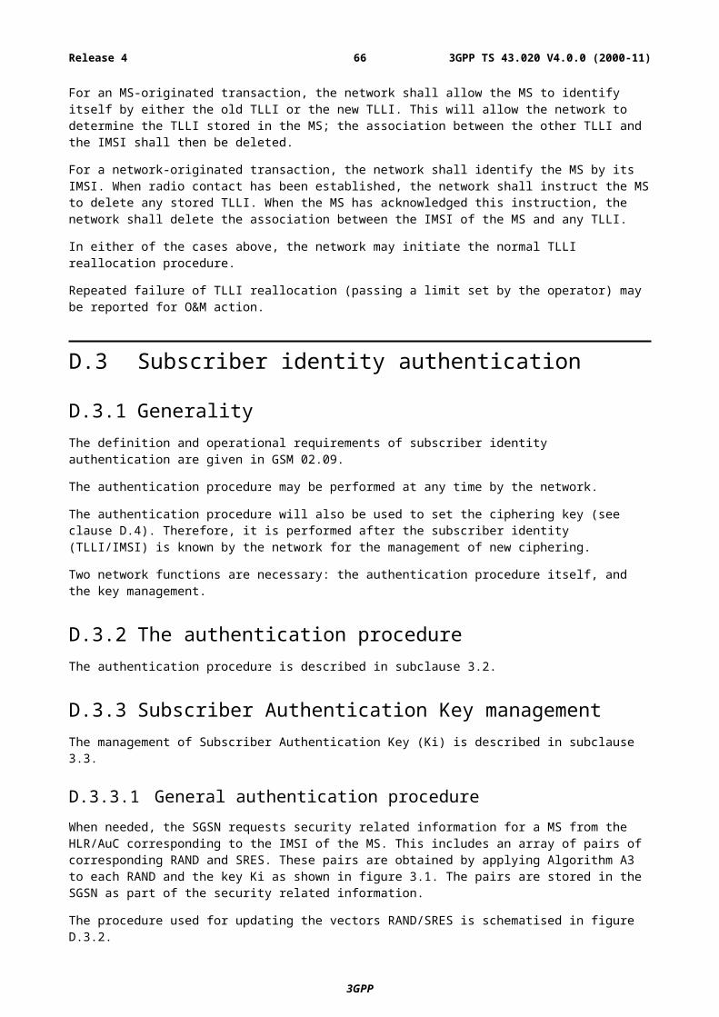
Annex E (normative):GSM Cordless Telephony System (CTS), (Phase 1); Security related network functions; Stage 2This annex is defining the security related service and functions for the GSM Cordless Telephone System (CTS).
This annex is only applicable if CTS is supported.
E.1 Introduction
E.1.1 ScopeThis annex specifies the functions needed to provide the security related services and functions specified in GSM 02.56.
E.1.2 References1 GSM 01.04: "Digital cellular telecommunications system (Phase 2+); Abbreviations and
Acronyms".
[2] GSM 02.56: "Digital cellular telecommunications system (Phase 2+); GSM Cordless Telephone System (CTS) Phase 1; Service Description; Stage 1".
[3] GSM 02.09: "Digital cellular telecommunications system(Phase 2+); Security Aspects".
4 GSM 03.56: "Digital cellular telecommunications system (Phase 2+); GSM Cordless Telephone System (CTS), Phase 1; CTS Architecture Description; Stage 2".
5 GSM 11.11: "Digital cellular telecommunications system (Phase 2+); Specification of the Subscriber Identity Module- Mobile Equipment (SIM-ME) interface".
[6] CCITT Recommendation T.50: "International Alphabet No. 5". (ISO 646: 1983, Information processing - ISO 7-bits coded characters set for information interchange).
7 GSM 03.20: "Digital cellular telecommunications system (Phase 2+); Security related network functions";
8 GSM 04.57: "Digital cellular telecommunications system (Phase 2+); CTS supervising system layer 3 specification ".
E.1.3 Definitions and Abbreviations
E.1.3.1 DefinitionsThe following list gives definitions which are used in this annex. For additional definitions related to CTS refer to the CTS stage 1 specification GSM 02.56.
Attachment: Attachment is the procedure where a CTS-MS accesses a CTS-FP either for local or over the fixed network communication or signalling. This procedure applies to CTS-MSs that have already been enrolled onto the CTS-FP.
CTS license exempt band: A frequency band that may be allocated by national regulator to CTS usage outside of a GSM license allocated to a GSM operator.
CTS licensed band: A frequency band that can be reserved by the operator for GSM-CTS usage or can be shared with the cellular system.
3GPP
3GPP TS 43.020 V4.0.0 (2000-11)66Release 4
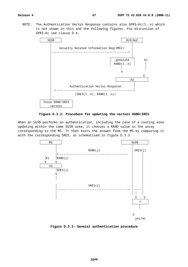
CTS Local security system: The term CTS local security system is used to describe all security aspects of a CTS-MS/CTS-FP pair.
CTS Operator: This term is used in this annex for any operator performing supervising security tasks in the CTS e.g. control of the CTS subscription or control of the CTS frequency usage. It is not considered here if this is one and the same PLMN operator for all supervising security tasks. However the security functions introduced here shall not restrict the system to be controlled by one specific PLMN operator.
CTS Supervising security system: The term CTS supervising security system is used to describe all security aspects of operation control of the local CTS from the GSM PLMN.
CTS-FP: The CTS Fixed Part consisting of the CTS-FPE and the FP-SIM.
CTS-MS: The CTS Mobile Station consisting of the CTS-ME and the MS-SIM.
Enrolment: The enrolment of a CTS-MS onto a CTS-FP is the procedure where a CTS-MS/CTS-FP pair is established locally and under the control of the CTS operator if license exempt band is used. A CTS-MS can only enrol onto a CTS-FP that has already been initialised.
FP-SIM: The SIM_FP is a GSM Phase 2+ SIM with additional data stored to allow CTS operation. This card is inserted in the CTS-FPE. The FP-SIM is only used in case of licensed band.
IFPSI: The IFPSI is a CTS specific subscriber identity stored in the FP-SIM card.
Initialisation: The initialisation of a CTS-FP is the procedure where the CTS-FP receives the necessary data to provide CTS service.
Local CTS: This term is used to describe all aspects of a CTS-MS/CTS-FP pair as seen from outside (from the GSM PLMN)
MS-SIM: The SIM_MS is a normal GSM Phase 2+ SIM according to GSM 11.11 with additional data stored to allow CTS operation. This card is inserted in the CTS-ME.
Operation data: This term is used as a place holder for any kind of data which is used to control CTS. The definition of this data, if it is not directly related to the CTS security aspects, is defined in other parts of the CTS specifications.
E.1.3.2 AbbreviationsThe following list describes the abbreviations and acronyms used in this annex. The GSM abbreviations defined in GSM 01.04 and in the CTS stage 1 specification GSM 02.56 are not included below.
B1 CTS ciphering key generation algorithmB2 CTS authentication key generation algorithmB3 CTS authentication algorithm (calculating the signed response of the CTS-FP challenge CH1)B4 CTS authentication algorithm (calculating the signed response of the CTS-MS challenge CH2)B5 CTS message authentication algorithm (for the authentication of the CTS-FP by the CTS-SN)B6 CTS message authentication algorithm (for the authentication of the signature issued by the
CTS-SN)CH1 CTS random Challenge value of the CTS-FPCH2 CTS random Challenge value of the CTS-MSCTS HLR CTS Home Location Register Functional EntityCTS-FP CTS-Fixed PartCTS-FPE CTS-Fixed Part EquipmentCTS-ME CTS-Mobile EquipmentCTSMSI CTS Mobile Subscriber Identity related to the x-th CTS-MS enrolled on a CTS-FPCTS-PIN CTS-Personal Identification NumberCTS-SNFPAC Fixed part authorisation code (derived from the CTS-PIN)FP-SIM Fixed Part CTS-Subscriber Identity ModuleIFPEI International Fixed Part Equipment IdentityIFPSI International Fixed Part Subscription IdentityKa CTS authentication key related to the x-th CTS-MS enrolled on a CTS-FPKc CTS ciphering key related to the CTS-MS enrolled on a CTS-FPKiFP CTS subscription authentication key (used for authentication of the CTS-FP by the CTS operator)
3GPP
3GPP TS 43.020 V4.0.0 (2000-11)67Release 4
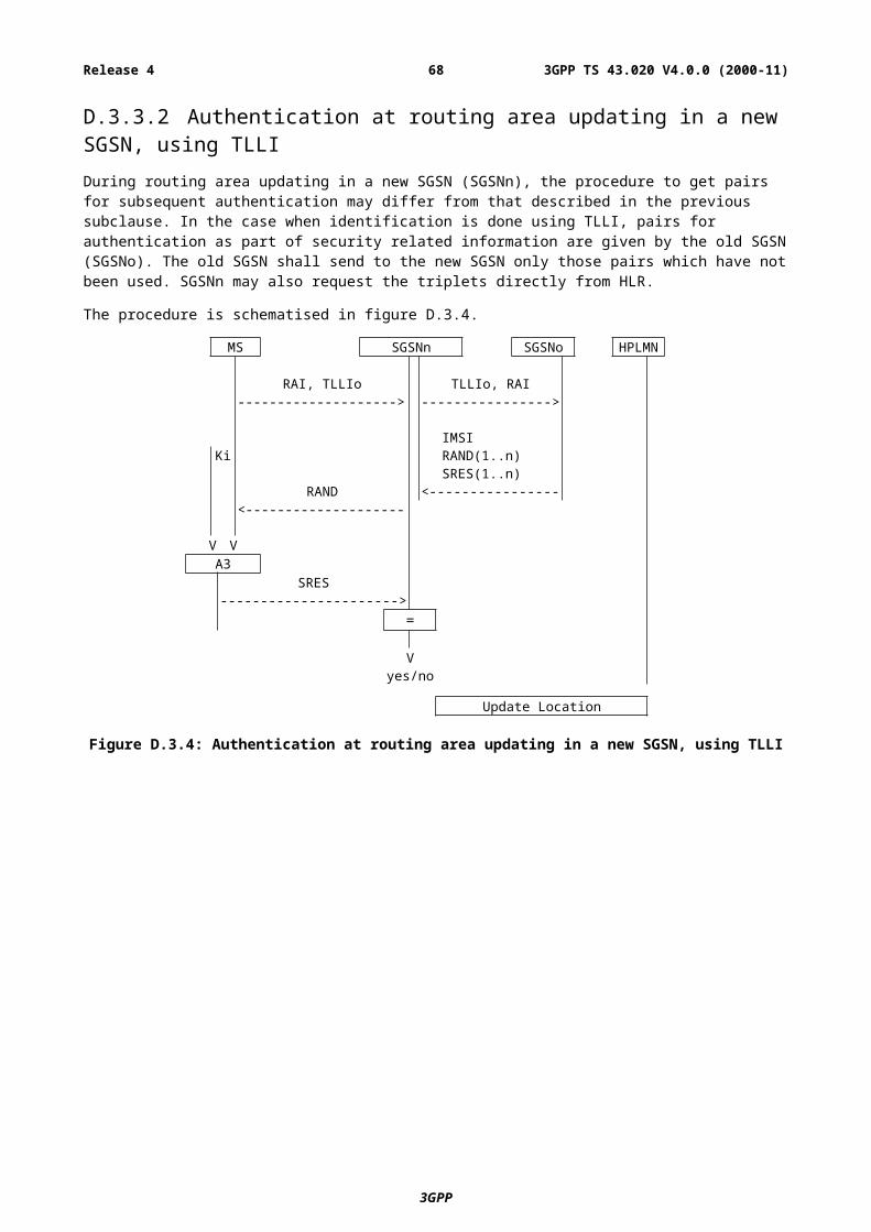
KOP Secret key used to validate tokens signed by the operatorMS-SIM Mobile CTS-Subscriber Identity ModuleRIFP CTS Random Initial value sent from the CTS-MS to the CTS-FPRIMS CTS Random Initial value sent from the CTS-FP to the CTS-MSSRES1 CTS Signed RESponse of the CTS-FP’s CH1 and the Ka of the CTS-MSSRES2 CTS Signed RESponse of the CTS-MS’s CH2 and the Ka of the CTS-FPTvalXSRES1 CTS Signed RESponse of the CTS-FP’s CH1 and the Ka of the CTS-FP (to be compared with
SRES1)XSRES2 CTS Signed RESponse of the CTS-MS’s CH2 and the Ka of the CTS-MS (to be compared with
SRES2)
E.2 GeneralIn GSM 02.56 the CTS service is introduced and security service requirements are listed. Based on this, the CTS security system can be seen as a set of two subsystems, the CTS local security system and the CTS supervising security system.
The local security system deals with aspects of CTS-MS/CTS-FP pairs. It is related to security aspects of the CTS user. The different CTS local security services, functions and procedures that are listed in GSM 02.56 are grouped as follows:
- MS subscriber identity confidentiality;
- identity authentication (including the MS subscriber identity - and the FP subscriber identity authentication);
- confidentiality of user and signalling information between CTS-MS and CTS-FP.
These functions are part of the following procedures:
- local part of the CTS enrolment/de-enrolment procedures;
- access procedure of a CTS-MS/CTS-FP pair.
When licensed band is used, the supervising security system deals with aspects of network security. It is related to security aspects of the CTS operator. The different CTS supervising security services, functions and procedures that are listed in GSM 02.56 are grouped as follow:
- identity authentication with the CTS operator (including the FP subscriber authentication and if required the MS subscriber authentication with the GSM operator);
- secure operation control;
- subscription Control;
- equipment checking (IMEI, IFPEI).
These functions are part of the following procedures:
- CTS system initialisation/de-initialisation procedures;
- CTS supervising security part of the CTS enrolment procedure;
- CTS-FP/CTS-SN Access procedure;
General comments on the figures in this annex:
- in the figures below, signalling exchanges are referred by functional names;
- signalling refers to exchange of information. This shall not imply any implementation of information elements and messages at this stage of the CTS specification.
- addressing fields are not given; all information relates to the signalling layer.
3GPP
3GPP TS 43.020 V4.0.0 (2000-11)68Release 4
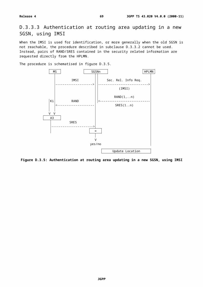
E.3 CTS local security systemThe subclauses below are described under normal operation. Abnormal operation is described in document [4].
The CTS local security applies for licensed band or license exempt band.
In the following sub-clauses the functions and procedures related to the CTS local security are defined. The following system elements and interfaces according to GSM 03.56 are involved:
- The CTS-FP (consisting of the CTS-FPE and the FP-SIM);
- The CTS-MS (consisting of the CTS-ME and the MS-SIM);
- The CTS radio interface between the CTS-MS and the CTS-FP.
E.3.1 Mobile Subscriber identity confidentialityThe purpose of this function is to avoid the possibility of an intruder identifying which subscriber is present on the CTS radio interface by listening to signalling exchanges or the user traffic. This allows both a high level of confidentiality for user data and signalling against the tracing of users.
The provision of this function implies that the mobile subscriber identity (IMSI), or any information allowing a listener to derive the identity easily, should not normally be transmitted in clear text in any signalling message on the CTS radio interface. Consequently, to obtain the required level of protection, it is necessary that:
- the subscriber identity (IMSI) is not normally used as an addressing method on the CTS radio interface (see GSM 02.09);
- when the signalling procedures and operating conditions (see GSM 03.56) permit it; signalling information elements that convey information about the mobile subscriber identity shall be ciphered for transmission on the CTS radio interface.
E.3.1.1 Identifying methodThe means used to identify a mobile subscriber on the CTS radio interface consists of a CTSMSI (CTS Mobile Subscriber Identity). This CTSMSI is a local number, having a meaning only for a given CTS-MS/CTS-FP pair.
The CTSMSI is assigned by the CTS-FP to the CTS-MS by signalling procedures at enrolment and is valid until updated by the CTS-FP. During normal operation, this CTSMSI identifies a CTS-MS uniquely among all CTS-MSs enrolled onto one CTS-FP.
See also GSM 03.56.
The CTS-MS shall store the CTSMSI in the MS-SIM, together with the IFPEI.
The CTS-FP shall store the CTSMSI in the CTS-FPE, together with the IMEI and the IMSI. The IMEI is stored in order to allow tracking of mobile equipment as required in GSM 02.56.
The storage requirements are given in clause E.9.
E.3.1.2 ProceduresThis subclause presents the procedures, or elements of procedures, pertaining to the management of the CTSMSI with respect to the local security.
E.3.1.2.1 CTSMSI assignment
This procedure is part of the enrolment procedure of a CTS-MS onto a CTS-FP (see subclause E.3.4.1).
The CTS-FP generates randomly a CTSMSI not equal to any of the existing CTSMSIs stored in the CTS-FP. The resulting CTSMSI is sent encrypted to the CTS-MS.
3GPP
3GPP TS 43.020 V4.0.0 (2000-11)69Release 4
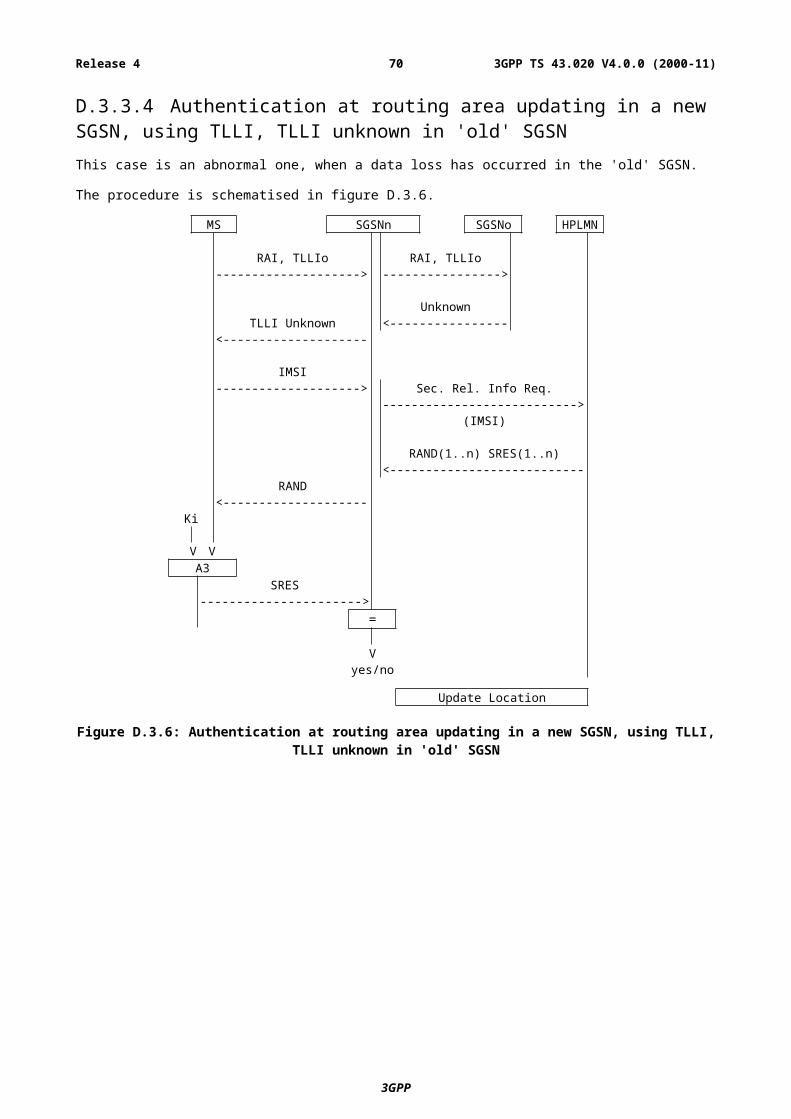
E.3.1.2.2 CTSMSI update
This procedure is part of general access procedure of a CTS-MS/CTS-FP pair.
The CTSMSI shall be updated by the CTS-FP as part of each MS/FP signalling exchange in order to preserve identity confidentiality. The CTS-FP generates randomly a CTSMSI not equal to any of the existing CTSMSIs stored in the CTS-FP. The resulting CTSMSI is the new CTSMSI for the CTS-MS/CTS-FP pair and is sent encrypted to the accessing CTS-MS. The CTS-MS stores the new CTSMSI on the MS-SIM. After successful storage, it acknowledges the update of the CTSMSI to the CTS-FP. Upon reception of the acknowledgement from the CTS-MS, the CTS-FP stores the new CTSMSI and deletes the old CTSMSI.
See also GSM 03.56.
E.3.1.2.3 CTS local identification
This procedure is part of general access procedures of a CTS-MS/CTS-FP pair.
The CTS-MS transmits the CTSMSI to the CTS-FP in the initial message in order to give its identity.
If the CTS-MS announces a CTSMSI which is unknown at the CTS-FP, then the CTS-FP requires the IMSI; if the IMSI is unknown, the CTS-FP shall deny access to that CTS-MS. The CTS-FP may consider that the CTS-MS is not enrolled into it.
The reason that the CTSMSI is unknown is generally not a matter of security and not considered here.
See also GSM 03.56.
E.3.2 Identity authenticationAccording to the definitions given in GSM 02.56, a local mutual authentication is required, containing both, the authentication of the mobile subscriber identity at the CTS-FP and the authentication of the CTS-FP identity at the CTS-MS.
It can be noted that the IMSI is not tied to the equipment identity (IMEI) as the security related data derived from the enrolment procedure are stored on the MS-SIM; therefore a subscriber can remove his MS-SIM card and insert it in another CTS-ME without locally re-enrolling onto the CTS-FP.
The authentication procedure will also be used to set the ciphering key (see subclause E.3.3).
E.3.2.1 The mutual authentication procedureA pre-condition of the procedure described below is, that both involved parties, the CTS-MS and the CTS-FP share the knowledge of the authentication key Ka.
The authentication procedure consists of the following exchange between the CTS-FP and the CTS-MS:
- The CTS-FP transmits an unpredictable number CH1 to the CTS-MS;
- The CTS-MS transmits an unpredictable number CH2 to the CTS-FP;
- The CTS-MS computes the response SRES1 from CH1 and the individual authentication key Ka using the algorithm B3;
- The CTS-FP computes the expected response XSRES1 from CH1 and the individual authentication key Ka using the algorithm B3;
- The CTS-MS transmits SRES1 to the CTS-FP;
- The CTS-FP tests SRES1 for validity, i.e. it compares SRES1 and XSRES1;
- The CTS-FP computes the response SRES2 from CH2 and the individual authentication key Ka using the algorithm B4;
3GPP
3GPP TS 43.020 V4.0.0 (2000-11)70Release 4
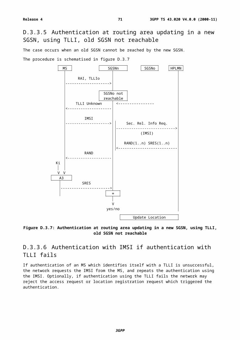
- The CTS-MS computes the expected response XSRES2 from CH2 and the individual authentication key Ka using the algorithm B4;
- The CTS-FP transmits SRES2 to the CTS-MS;
- The CTS-MS tests SRES2 for validity, i.e. it compares SRES2 and XSRES2.
Note that the order of transmission of information as mentioned above and as shown in the figure shall not imply any implementation. Protocols to exchange the information shall be implemented with respect to efficiency of calculation time and effective messaging.
Figure E1: General mutual authentication procedure
E.3.2.1.1 Authentication failure
An authentication failure (from security point of view) occurs, if:
- The CTS-MS and the CTS-FP have different Ka;
- The algorithm B3 or B4 are not implemented as specified (i.e. non type approved equipment).
In this case the side which has detected the failure shall indicate "authentication failure" to the other side and cancel the connection with the other side.
E.3.2.2 Authentication Key management.The Ka associated with a CTS-MS/CTS-FP pair is generated randomly during enrolment procedure as described in subclause E.3.4.1. As defined in GSM 02.56, keys of the CTS shall be controlled by the PLMN operator. In order to fulfil this requirement, all relevant information to reproduce Ka is transmitted to the PLMN operator as described in subclause E.3.4.1 and in subclause E.4.
3GPP
3GPP TS 43.020 V4.0.0 (2000-11)71Release 4
E.3.3 Confidentiality of user information and signalling between CTS-MS and CTS-FPIn GSM 02.56 some signalling information is considered sensitive and must be protected.
The needs for a protected mode of transmission are fulfilled with an OSI layer 1 confidentiality function. The scheme described below assumes that the signalling information is transmitted on a dedicated channel.
Four points have to be specified:
- the ciphering method;
- the key setting;
- the starting of the enciphering and deciphering algorithms;
- the synchronisation.
E.3.3.1 The ciphering methodThe OSI layer 1 data flow (transmitted on a dedicated channel) is ciphered on a bit by bit basis or stream cipher; i.e.; the data flow on the CTS radio interface is obtained by the bit per bit binary addition of the user data flow and the ciphering bit stream generated by the algorithm A5/2 using a key determined as specified in subclause E.10.1. The key is denoted below by Kc and is called the CTS Ciphering Key. The Kc is specific to one CTS-MS/CTS-FP pair.
Deciphering is performed by exactly the same method.
Algorithm A5/2 is one of the A5 algorithms specified in GSM 03.20, Annex C. Only A5/2 algorithm is supported on the CTS-FP to enable local ciphering. The CTS-MS supports at least the A5/2 algorithm.
E.3.3.2 Key settingMutual key setting is the procedure that allows the CTS-MS and the CTS-FP to agree on the key Kc to use in the ciphering and deciphering algorithm A5/2.
A key setting is triggered by the mutual authentication procedure.
Key setting must occur on a channel not yet encrypted and as soon as the CTSMSI is known by the CTS-FP.
Kc is generated using CH1, the algorithm B1 and the CTS Authentication key Ka, as defined in subclause E.10.1. Kc is stored in the CTS-ME and the CTS-FPE as described in subclause E.8.
3GPP
3GPP TS 43.020 V4.0.0 (2000-11)72Release 4
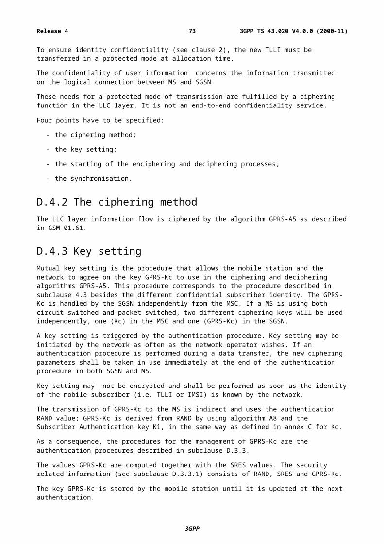
Figure E2: Cipher Key setting
E.3.3.3 Starting of the ciphering and deciphering processesThe CTS-MS and the CTS-FP must co-ordinate the instants at which the enciphering and deciphering processes start. This procedure takes place under control of the CTS-FP some time after the completion of the authentication procedure. No information elements for which protection is needed must be sent before the ciphering and deciphering processes are operating.
The transition from clear text mode to ciphered mode proceeds as follows:
The CTS-FP starts deciphering and sends in clear text to the CTS-MS a specific message, here called "Start cipher". After the message "Start cipher" has been correctly received by the CTS-MS, the CTS-MS will commence both the enciphering and deciphering. Finally, enciphering in the CTS-FP starts as soon as a frame or a message from the CTS-MS has been correctly deciphered at the CTS-FP.
The starting of enciphering and deciphering processes is shown in figure E3.
3GPP
3GPP TS 43.020 V4.0.0 (2000-11)73Release 4
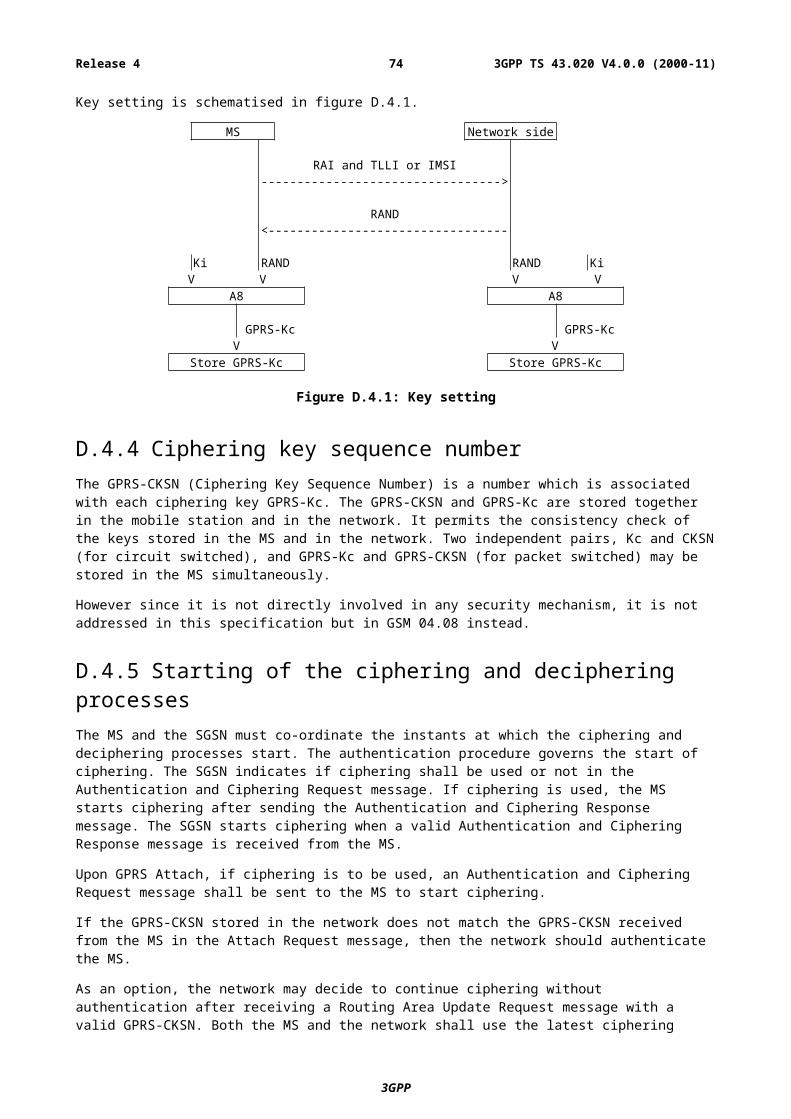
Figure E3: Starting of the enciphering and deciphering processes
E.3.3.4 SynchronisationThe ciphering stream at one end and the deciphering stream at the other end must be synchronised, for the enciphering bit stream and the deciphering bit stream to coincide. The underlying synchronisation scheme is described in GSM 03.20, Annex C.
E.3.4 Structured procedures with CTS local security relevanceThe following structured procedures are mainly related to the local security or at least involve CTS local security functions and procedures.
E.3.4.1 Local Part of the Enrolment of a CTS-MS onto a CTS-FP According to GSM 02.56 and GSM 03.56 the CTS-MS/CTS-FP enrolment is the procedure, which generates an association between a certain CTS-MS and a certain CTS-FP, i.e. a CTS-MS/CTS-FP pair is established. The following CTS local security aspects are covered by the enrolment:
- The enrolment includes a means of authorisation to use the CTS-FP, i.e. the CTS-PIN is necessary in the enrolment procedure. It is mandatory that the CTS-PIN is activated.
- The authentication key Ka is generated and distributed to the CTS-MS and the CTS-FP.
- The CTSMSI is initially allocated and submitted from the CTS-FP to the CTS-MS
- The IFPEI is transmitted from the CTS-FP to the CTS-MS.
3GPP
3GPP TS 43.020 V4.0.0 (2000-11)74Release 4
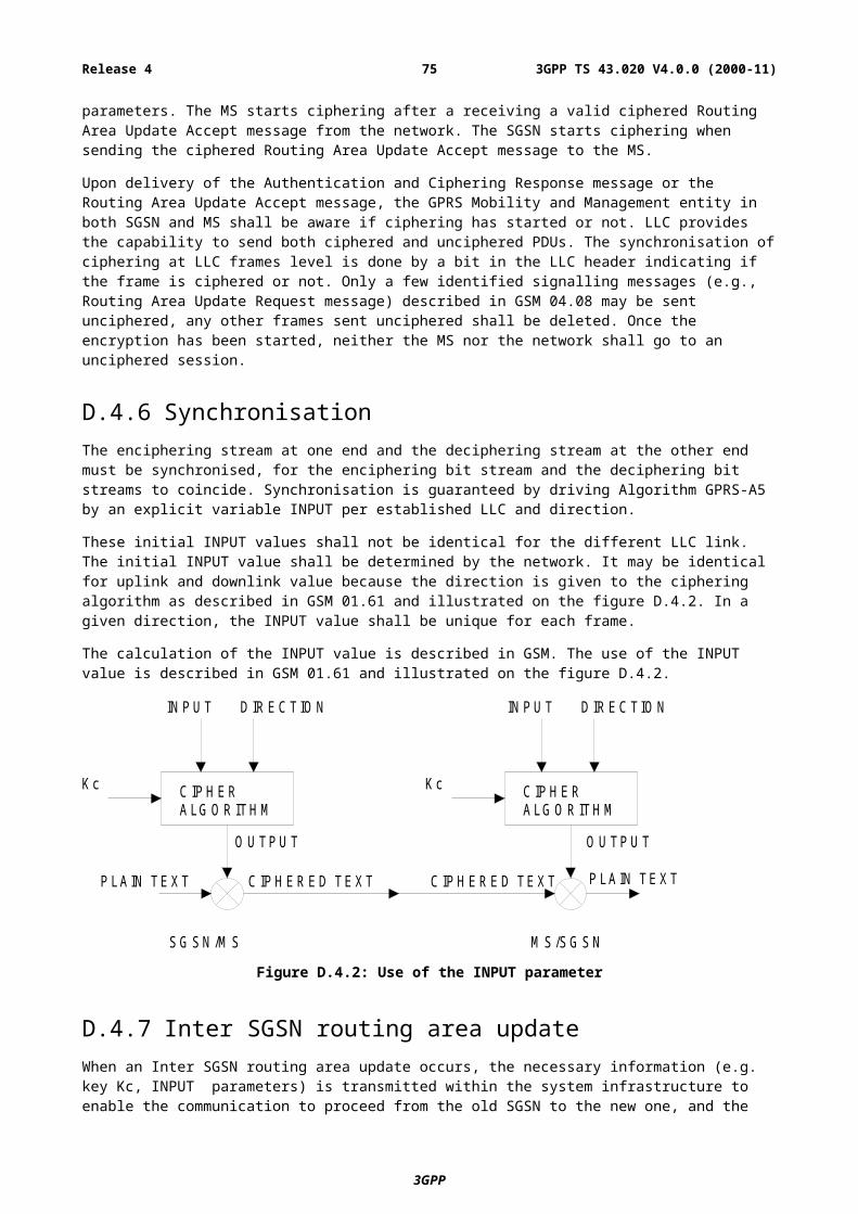
E.3.4.1.1 Local part of the enrolment procedure
The procedure described assumes that the CTS-MS or the CTS-FP have the knowledge of the radio parameters to be used on the CTS radio interface to enable initial connection (see GSM 02.56 and GSM 03.56).
As specified in GSM 02.56 and GSM 03.56, only a CTS-MS subscribed to an operator which has roaming agreement with the CTS-FP’s operator shall be allowed to enrol to that CTS-FP.
The following procedure is followed:
- An enrolment state is triggered by MMI at the CTS-MS and at the CTS-FP;
- The user enters the CTS-PIN at the CTS-MS;
- The CTS-MS derives the FPAC from the CTS-PIN. The FPAC also resides in the CTS-FP, thus the knowledge of the CTS-PIN gives authorisation to perform enrolment;
- An initial connection is established on the CTS radio interface;
- The CTS-MS and the CTS-FP exchange random initial values (RIMS and RIFP);
- The CTS-MS and the CTS-FP both calculate an authentication key Ka = B2(FPAC, RIMS, RIFP);
- The CTS-MS and CTS-FP perform a mutual authentication according to subclause 3.2.1 using Ka . Since Ka is derived from the CTS-PIN, this mutual authentication proves the authorisation of the user;
- The CTS-MS and CTS-FP determine a ciphering key Kc = B1(Ka, RIMS) and switch to ciphering mode according to the procedure described in subclause E.3.3;
- The CTS-MS transmits (encrypted) to the CTS-FP the IMSI, and the IMEI;
- In order to avoid double enrolment, the CTS-FP checks if the IMSI is already enrolled;
- The CTS-FP checks the GSM operator’s identity of the CTS-MS and determines whether the CTS-MS subscriber is allowed to enrol on that CTS-FP;
- In case of licensed band the Supervising part of the enrolment is performed if required (see subclause E.4.4.3.4.);
- The CTS-FP determines the CTSMSI;
- The CTS-FP transmits (encrypted) the Ka, the IFPEI and the CTSMSI;
- The CTS-MS stores the Ka, the CTSMSI and the IFPEI on the MS-SIM;
- The CTS-FP stores the Ka, the IMSI, the IMEI, CTSMSI in a non volatile memory of the CTS-FPE;
- The enrolment procedure is completed (possible non security related procedures).
If a failure occurs during this local security procedure, intermediate values related to this procedure shall be deleted and the enrolment shall be aborted.
3GPP
3GPP TS 43.020 V4.0.0 (2000-11)75Release 4
Figure E4: Local part of the enrolment procedure
3GPP
3GPP TS 43.020 V4.0.0 (2000-11)76Release 4
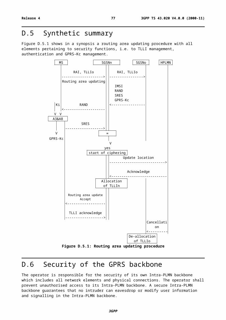
E.3.4.2 General Access procedureOnce the CTS-MS is enrolled onto a CTS-FP, the CTS-MS may access the CTS-FP for user communication on the fixed network or for local CTS related procedures or as part of the local security for CTS supervising procedures. The access procedures shall generally involve the following sub-procedures:
- Identification as described in subclause E.3.1.2;
- Mutual authentication using the Ka defined during the enrolment in order to authenticate the identities on the CTS radio interface as described in subclause E.3.2.1;
- Generation of a new Kc and starting to cipher the link on the CTS radio interface as described in subclause E.3.3;
- Update of the CTSMSI because it has been used in clear text for identification, as described in subclause E.3.1.2.2;
Figure E5: The general access procedure
Authentication and start of ciphered connection shall usually be performed before any sensitive signalling data or user data is transmitted on the CTS radio interface. In the following sub-subclauses, some specific access procedures are described with respect the CTS local security.
E.3.4.2.1 Attachment
The attachment procedure is used to attach a CTS-MS to a CTS-FP. A pre-condition is, that the CTS-MS is enrolled with the CTS-FP.
The attachment procedure shall be performed whenever the CTS-MS is switched on within the range of a CTS-FP or when it comes into the range of the CTS-FP.
The attachment procedure shall include all sub-procedures of the general access procedure as described above.
Additionally the IMEI of the CTS-MS may be transmitted to the CTS-FP at attachment, in order to support the tracking or IMEI as described in subclause E.4.5.
3GPP
3GPP TS 43.020 V4.0.0 (2000-11)77Release 4
E.3.4.2.2 CTS local security data update
The CTS local security data update procedure is performed in order to determine a new temporary identity CTSMSI and a new cipher key Kc. This procedure may be a part of a non security related procedure or it is used for the main purpose of local security data update.
A regular CTSMSI update procedure shall be defined in order to insure user confidentiality.
The CTS local security data update contains all sub-procedures of the general access procedure. It is initiated by the CTS-FP.
E.3.4.3 De-enrolment of a CTS-MSAccording to GSM 02.56 the de-enrolment of a CTS-MS is the procedure which cancels the association between a certain CTS-MS and a certain CTS-FP.
A de-enrolment procedure of a CTS-MS from a CTS-FP can be either initiated by the CTS-FP (network or FP command) or by a user specific action to de-enrol one or several CTS-MS from a CTS-FP.
E.3.4.3.1 De-enrolment initiated by the CTS-FP
The following procedure is followed:
- The CTS-FP sends a de-enrolment command to the CTS-MS;
- The CTS-MS and the CTS-FP perform mutual authentication according to subclause E.3.2.1 using Ka;
- The CTS-MS deletes data related to CTS-FP i.e. Ka, CTSMSI, IFPEI, and confirms de-enrolment;
- The CTS-FP deletes data related to that CTS-MS i.e. Ka, CTSMSI, IMSI, IMEI;
- The de-enrolment is completed (possible non security related procedures).
E.3.4.3.2 De-enrolment initiated by a CTS-MS
The de-enrolment procedure when initiated by a CTS-MS is an MMI procedure that requires the knowledge of the CTS-PIN. The following procedure applies:
When remote MMI is used:
- the user enters a specific de-enrolment menu or command at the CTS-MS;
- attachment is performed on the MS/FP interface;
- the user enters the CTS-PIN at the CTS-MS;
- The CTS-FP checks the CTS-PIN and sends a list of all enrolled CTS-MSs to the CTS-MS;
- The list is displayed at the CTS-MS and the user selects one (or several) CTS-MS(s) for de-enrolment;
- The list of CTS-MS(s) which are selected for de-enrolment, is sent to the CTS-FP;
- Data related to the de-enrolled CTS-MSs, i.e. the Ka, the IMSI, the CTSMSI, the IMEI are deleted in the CTS-FP;
- The de-enrolment is completed (possible non security related procedures).
3GPP
3GPP TS 43.020 V4.0.0 (2000-11)78Release 4
E.4 CTS supervising security systemThis subclause is applicable is case of licensed band only.
In the following sub-clauses the functions and procedures related to the CTS supervising security are defined. The following system elements and interfaces according to GSM 03.56 are involved:
- The CTS-FP (consisting of the CTS-FPE and the FP-SIM);
- The CTS-MS (consisting of the CTS-ME and the MS-SIM);
- The CTSHLR/AuC;
- The CTS-SN;
- The HLR/AuC;
- The CTS radio interface between the CTS-MS and the CTS-FP;
- The CTS fixed network interface;
- The GSM radio interface.
E.4.1 Supervision data and supervision data protectionThis sub-clause describes the mechanisms to be used by theCTS operator to set and modify the supervision data to be used in a CTS-MS/CTS-FP environment.
E.4.1.1 Structure of supervision dataSupervision data are sent as structured information elements which may consist of:
1 Short commands, e.g., information data requests, identification, de-intialisation of the CTS-FP,de-enrolment of a CTS-MS, ...;
2 Download of data and parameters, e.g., radio parameters, timer settings, CTS-SN directory number;
E.4.1.2 Supervision data protectionThe supervision data are protected by a signature.
The signature of data is performed following a valid CTS-FP authentication by the CTS-SN as described in chapter E.4.3.1.
The signature is performed using the B6 algorithm and a secret key Kop shared between the CTS-SN and the CTS-FP. The secret key Kop is generated during the CTS-FP authentication at the CTS-AuC using the authentication key KiFP a random vector and the A8’ algorithm: Kop= A8’(KiFP, RAND1).
Data signature is performed using a random vector RAND2 generated by the CTS-FP, Data the sequence that has been signed, Kop and the B6 algorithm. The concatenation of Data and RAND2 is referred to as Data2.
Some data are associated with a validity period indication (relative time). Before the validity timer expires, the CTS-FP must contact the CTS-SN in order toupdate those data.
It should be noted that supervision data carry data related to CTS subscription and therefore to the CTS-FP.
Therefore, the operator will issue supervision data following a successful CTS-FP authentication by the CTS-HLR.
3GPP
3GPP TS 43.020 V4.0.0 (2000-11)79Release 4

Figure E6: Generation of the signature of the supervision data
E.4.1.3 Key managementThe SIM card manufacturer delivers an FP-SIM card that includes a mechanism to authenticate the signature of the supervision data issued by the CTS-SN. This mechanism consists of the B6 algorithm that enables authentication of thesignature using a secret key KOP.
This key is not accessible on the FP-SIM card.
E.4.2 CTS subscriber identity A CTS specific identity is assigned to a subscriber of the CTS service. This identity (IFPSI) enables unique identification of a CTS subscriber at communication with the CTS-SN.
It can be noted that the subscription to the CTS service does not assume subscription of every CTS-MS that want to operate CTS on a given CTS-FP. There is one CTS subscription per CTS-FP, and therefore one identity to check no matter how many CTS-MS are enrolled to that CTS-FP.
Nevertheless, the CTS operator may also require the authentication of the CTS-MS.
And therefore the MS-SIM identity (IMSI) will identify a CTS-MS subscriber at communication with the CTS-SN.
For more details see also GSM 03.56.
E.4.3 Identity authentication with the CTS operator and the PLMNAccording to the definitions given in GSM 02.56, the procedure of authentication of the FP-SIM is required for the CTS initialisation, CTS-MS enrolment onto a CTS-FP, and network access procedure (e.g. operation data update).
Similarly, the procedure of authentication of the MS-SIM is required for the CTS-MS enrolment onto a CTS-FP.
Additionally identity authentication may also be part of other CTS specific procedures.
3GPP
3GPP TS 43.020 V4.0.0 (2000-11)80Release 4
E.4.3.1 Authentication of the CTS-FPThe authentication of the CTS-FP via the fixed network procedure consists of the following exchange between the CTS-FP and the CTS-HLR through the CTS-SN:
- The CTS-FP sends the IFPSI to the CTS-HLR through the fixed line and through the CTS-SN;
- The CTS-AuC computes the authentication result (SRES) using the KiFP key associated to the IFPSI and a random challenge (RAND);
- The CTS-SN receives from the CTS-HLR the authentication vector (SRES (1,…, n), RAND (1,…,n)) according to the general authentication procedure described in GSM 03.20;
- The CTS-SN transmits a RAND1 and a random value Data1 to the CTS-FP via the fixed network;
- The CTS-FP and the CTS-HLR generate a key Kop derived from the KiFP and using A8’ algorithm;
- The CTS-FP performs an authentication using Kop and B5 computes the signature ofData1, say MAC1;
- The CTS-FP transmits the signature MAC1 to the CTS-SN;
- The CTS-SN tests MAC1 for validity.
Figure E7: Authentication of the CTS-FP
E.4.3.2 Authentication of the CTS-MSThis procedure requires that the CTS-SN has an interface to the HLR in order to receive the challenge/response pairs for authentication of the CTS-MS.
It is a normal GSM authentication procedure as described in GSM03.20[7], the CTS-FP acting as a relay:
- The CTS-MS sends the IMSI to the HLR through the CTS-FP and through the CTS-SN;
- The AuC generates the authentication result (SRES) using the Ki key associated with the IMSI and a random challenge (RAND);
- The CTS-SN receives the authentication vector (SRES (1,…, n), RAND (1,…,n)) according to the general authentication procedure described in GSM 03.20;
- The CTS-SN transmits a RAND, 1 x n, to the CTS-MS via the CTS-FP.;
- The CTS-MS performs an authentication using Ki and A3 according to the authentication procedure described in GSM 03.20 and computes the signature of RANDx: SRESRANDx;
- The CTS-MS transmits via the CTS-FP the signature SRESRANDx to the CTS-SN;
3GPP
3GPP TS 43.020 V4.0.0 (2000-11)81Release 4
- The CTS-SN tests SRESRANDx for validity.
Figure E8: Authentication of the CTS-MS via the CTS fixed network interface
E.4.4 Secure operation controlAccording to GSM 03.56, signalling for operation control of the local CTS may take place on different signalling planes:
- on the CTS fixed network interface using a CTS-SN application signalling;
- on the GSM Radio Interface using the GSM layer 3 signalling.
The means of operation control of the local CTS for these two signalling planes is described in the subsequent subclauses.
E.4.4.1 GSM layer 3 signallingGSM layer 3 signalling can be used to provide CTS data.
It is not initiated on request of the local CTS but included in a normal GSM layer 3 signalling procedure.
These data are downloaded to the CTS-MS through the GSM Radio Interface and transferred to the CTS-FP during an access procedure according to subclause E.3.4.2. Whenever the CTS-FP gets new CTS operation data it contacts the CTS-SN through the Fixed Network and performs Operation Data Update procedure according to subclause E.4.4.3.4.1.
E.4.4.2 CTS application signalling via the Fixed NetworkCTS may use a specific application protocol on the fixed network interface for operation control purposes. Communication via the fixed network interface may include authentication of the subscriber identity as described in subclause E.3.2.
Due to the fact, that a false CTS-SN can easily be set up, protection of operation data as described in subclause E.4.1.2, is required.
Operation control via the CTS fixed network interface is generally initiated by the local CTS, i.e. the CTS-FP, triggered by time or event control.
An initiation from the CTS-SN to the CTS-FP, is generally not applicable due to missing means of addressing a specific terminal, i.e. the CTS-FP in the fixed network (PSTN case).
However, this shall not exclude that the CTS-SN initiate operation control, if certain network configurations allow this feature.
3GPP
3GPP TS 43.020 V4.0.0 (2000-11)82Release 4
E.4.4.3 CTS operation control procedures
E.4.4.3.1 Initialisation of a CTS-FP
According to GSM 02.56 and GSM 03.56 the CTS-FP initialisation is the procedure where the CTS-FP is downloaded with the necessary data in order to provide CTS service.
The following procedure applies:
- An initialisation state is triggered by MMI at the CTS-FP;
- The CTS-FP retrieves the CTS-SN directory number from the FP-SIM;
- The CTS-FP contacts the CTS-SN through the fixed line;
- Authentication of the CTS-FP is performed as described in subclause E.4.3.2.1;
- The CTS-SN sends operation data to the CTS-FP; these data are protected as described in subclause E.4.1.2;
- The CTS-FP authenticates the signature of the operation data sent from the CTS-SN;
- The CTS-FP is considered as being initialised.
E.4.4.3.2 De-initialisation of a CTS-FP
The CTS-FP is considered as being de-initialised if it does not have the necessary data to provide CTS service.
This may happen either because:
1 a timer associated to the CTS data has expired and therefore the CTS-FP cannot offer CTS service;
2 a network control mechanism requires CTS-FP de-initialisation;
3 the CTS-FP has been disconnected from the PSTN connection and from the main power for a period of time;
4 the FP-SIM has been removed and a new SIM card inserted in the CTS-FPE.
As the CTS-SN has in general no means to address the CTS-FP, the de-initialisation command is sent when the CTS-FP accesses the CTS-SN.
Case 1
The principle of the time/event controlled mechanism is, that some operation data has a limited validity period. The duration of this period, i.e. a timer, is controlled by the CTS operator.
The operation data is related to one CTS-subscriber that is to the FP-SIM. An authentication of the CTS-FP by the CTS-SN and a token authentication by the CTS-FP is performed in the operation data update procedure as described in subclause E.4.4.3.4.1.
Therefore, the update of the operation data does not require a CTS-MS being enrolled to the CTS-FP. Before the expiry of the validity period timer a data update procedure is triggered as described in subclause E.4.4.3.4.1.
If the validity period expires without an update of the operation data, the CTS-FP is de-initialised and the operation data are deleted from the CTS-FP.
Case 2
In case 2, the de-initialisation procedure is the following:
- The CTS-FP contacts the CTS-SN;
- The CTS-SN performs authentication of the CTS-FP as described in chapter E.4.3.2.1;
- The CTS-SN sends a de-initialisation command using the data protection mechanism described in chapter E.4.2.1;
3GPP
3GPP TS 43.020 V4.0.0 (2000-11)83Release 4
- The CTS-FP authenticates the signature and deletes the operation data;
- De-initialisation is performed.
The CTS-FP de-initialisation does not imply CTS-MS de-enrolment; the data related to CTS-MS/CTS-FP pair are not deleted from the CTS-FP but CTS service cannot be granted.
Case 3
As some operation data might be related to the location of the CTS-FP, if the CTS-FP is disconnected from the PSTN connection for a certain time (see [4]), the CTS-FP is considered as being de-initialised and the operation data are deleted from the CTS-FP.
Case 4
The operation data are related to the FP-SIM. If a new FP-SIM is inserted in the CTS-FPE the previously stored data should be deleted. The CTS-FP is therefore de-initialised.
E.4.4.3.3 Enrolment
From the CTS supervising security point of view the following requirements have to be fulfilled:
- According to the definitions given in the CTS stage 1 service description, enrolment shall include authentication of the CTS-subscriber (FP-SIM).
- In addition, if required by the CTS operator an authentication of the CTS-MS subscriber can be performed. (GSM 02.09).
- The local CTS shall receive operation data
- The CTS shall operate in accordance with the settings of this operation data.
Two supervising security methods are defined for enrolment. They are described in the subsequent subclauses.
E.4.4.3.3.1 Enrolment conducted via the CTS fixed network interface
If indicated by the CTS subscription information at the CTS-FP the supervising part of the enrolment is conducted via the CTS fixed network interface.
In this case, after the local part of the enrolment procedure is performed as described in subclause E.3.4.1.1 (we have reached the stage where the CTS-MS transmits through the CTS interface the IMSI, the CTS-FP checks that the IMSI is not enrolled yet), the following procedure applies:
- The CTS-FP calls the CTS-SN through the fixed line;
- The IFPSI and the IMSI are transmitted from the CTS-FP to the CTS-SN; Equipment identities (IMEI, IFPEI) can be transmitted for verification;
- The CTS-HLR performs authentication of the CTS-FP using the authentication key KiFP,A8’ and B5 authentication algorithm as described in subclause E.4.3.2.1;
- After successful authentication of the CTS-FP, the CTS-SN may require the authentication of the CTS-MS. The generation of triplets is achieved in the HLR using the Ki authentication key and the A3 algorithm as described in subclause E.4.3.2.2;
- The CTS-FP checks the validity of the signature as described in subclause E.4.1.2;
- The CTS-FP and the CTS-MS exchange data (as described in the local security part of the enrolment procedure (E.3.4.1.1);
- The CTS-FP indicates successful enrolment to the CTS-MS;
- The enrolment is finished.
3GPP
3GPP TS 43.020 V4.0.0 (2000-11)84Release 4
Figure E9: CTS supervising security: enrolment of a CTS-MS onto a CTS-FP via the CTS fixed network interface
E.4.4.3.4 Supervising security in the CTS-FP/CTS-SN access procedure
E.4.4.3.4.1 Update of operation data
The update of operation data is required due to the fact, that the validity of some operation data is limited by an operator controlled timer.
The operation data can be updated without a CTS-MS being attached to the CTS-FP, as FP-SIM authentication is performed through the fixed network interface. This allows transparency of the operation control to the user and avoids unnecessary de-initialisation if the user has not performed attachment for a long period of time.
Update of operation is performed via the fixed network interface and the following steps apply:
- Before the validity period expires, the CTS-FP contacts the CTS-SN and requires data update;
- The CTS-HLR authenticates the FP-SIM through the fixed network interface;
- the CTS-HLR checks the subscription validity and sends a new set of operation data to the CTS-FP;
- The CTS-FP authenticates the data signature and starts a new timer;
- The update procedure is finished.
3GPP
3GPP TS 43.020 V4.0.0 (2000-11)85Release 4
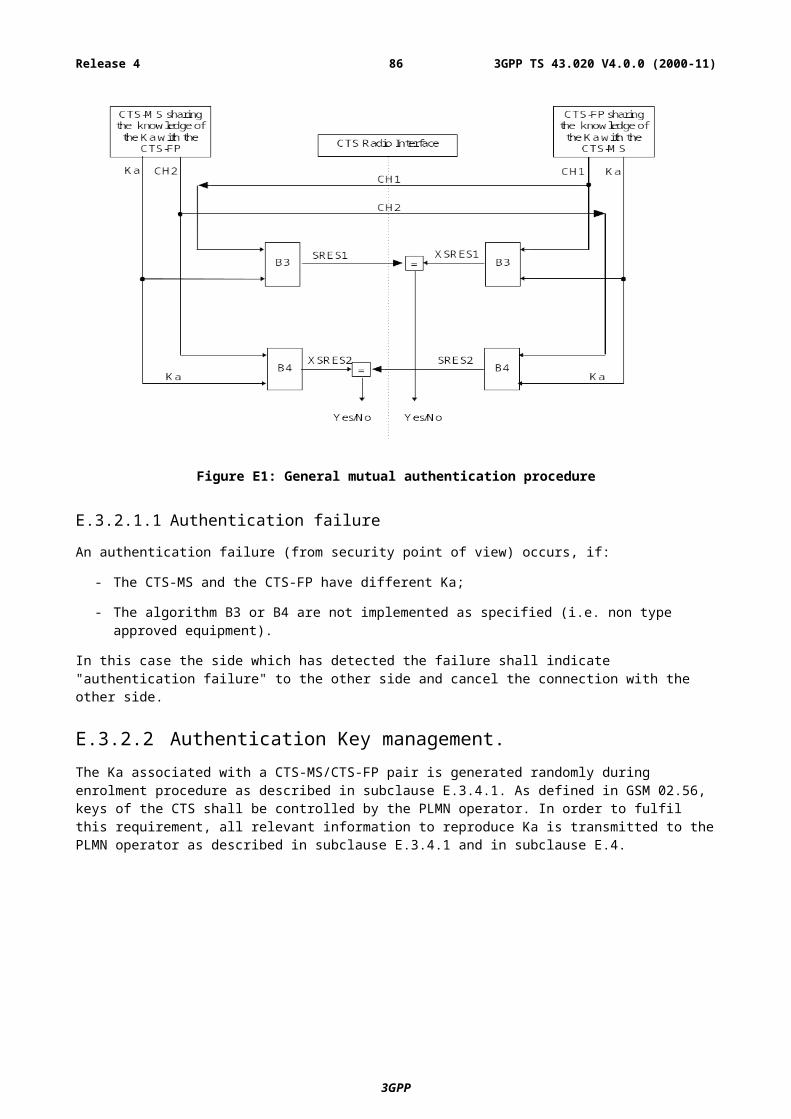
Figure E10: Update of operation data via the CTS fixed network interface
As this timer is an essential part of the CTS operation control, it shall be securely situated within the CTS-FP, i.e. it shall not be possible to reset the time except by valid operations described in this subclause. The security requirements on the timer values and the timer itself are described in subclause E.6.
E.4.5 Equipment checkingEquipment checking can be seen as part of the initialisation, of the enrolment or of the operation data update procedures:
Checking the IFPEI can be part of the initialisation and operation data update procedures.
Checking the IFPEI and the IMEI can be part of the enrolment procedure.
E.4.6 FP-SIM card checkingThe FP-SIM presence should be verified and no CTS operation should be allowed if the FP-SIM is not at least present. Furthermore, specific CTS operations should meet the following requirements:
- The CTS-FP initialisation procedure should not be possible if the CTS-FP does not include a valid FP-SIM card, i.e. that contain minimum information to contact the CTS-SN or to operate CTS service.
- The enrolment procedure of a CTS-MS on a CTS-FP should not be initiated if the MS-SIM operator’s identity is in the list of forbidden operators of the FP-SIM.
- CTS operation should not be allowed if there is not a valid FP-SIM card in the CTS-FPE.
The MS-SIM verification follows the normal GSM requirements. The GSM subscription is checked whenever the CTS-MS accesses the PLMN (authentication performed using the IMSI, Ki and A3 in the MS-SIM card).
3GPP
3GPP TS 43.020 V4.0.0 (2000-11)86Release 4
The MS-SIM card is not tied to the CTS-ME as all the relevant data for local security are stored in the MS-SIM card. If after successful enrolment on a given CTS-FP, the CTS-ME have been changed, no re-enrolment should be needed. The CTS-FP will store the new IMEI sent in the access procedure in association with the local security data.
If the FP-SIM card has been extracted from the CTS-FPE, the latter should check the identity of the new SIM card. If a new FP-SIM card has been inserted in the CTS-FPE, CTS-FP should be re-initialised.
E.5 Other CTS security featuresIn GSM 02.56 the requirements of a series of additional security services and functions for the CTS are defined. They should provide, amongst others, protection against misuse of equipment
This subclause describes the CTS security features that concern:
- secure storage of sensitive data in CTS-MS;
- secure storage of sensitive data in CTS-FP;
- CTS-FP de-initialisation;
- CTS-FP reprogramming protection.
E.5.1 Secure storage of sensitive data and software in the CTS-MS
E.5.1.1 Inside CTS-METhe storage of the IMEI should be according the requirements described in GSM 02.09. Secure storage of sensitive data inside non-volatile memory of the CTS-ME should follow the directives in GSM 02.56.
E.5.2 Secure storage of sensitive data and software in CTS-FPThe IFPEI is stored in the CTS-FPE according to the same requirements for storage of the IMEI as described in GSM 02.09. Other sensitive data shall be stored securely.
The timer for operation control should be stored in a secure way.
E.5.3 CTS-FP reprogramming protectionReprogramming shall only be possible by the manufacturer of the CTS-FP and authorised services. The specification of the method is up to the manufacturer.
E.6 FP IntegrityIn case of licensed mode, the CTS-FP while servicing its user(s) should perform as instructed by the CTS-SN. In both licensed and license exempt modes, a potential entry point for various kinds of CTS misuse would be to alter a type-approved CTS-FP. It is therefore of paramount importance that the local CTS security and in particular the CTS-FP itself provide reliable countermeasures against CTS-FP misuses through manipulation of its hardware and/or software. The purpose of this subclause is
a) to identify explicitly the threats
b) to explore ways how to provide protection
c) to consider the verification of protection mechanisms
3GPP
3GPP TS 43.020 V4.0.0 (2000-11)87Release 4

E.6.1 ThreatsThreats have been identified and the importance of the corresponding need for a countermeasure was classified. The following ranking was used:
1. Essential; Protection is essential for secure operation of CTS in general;
2. Important; Protection is important but failure has limited impact;
3. Desirable; Protection is desirable but failure has only local impact.
Table E1 shows the sensitive information that the FP contains and the importance of the countermeasure(s) against possible manipulation.
It is understood that when an item is mentioned in Table 1that changing its value in an unauthorised way is a threat.
Table E1: Sensitivity of FP maintained information
Item Type of data RankCTS-FP software (note 1) constant 1IFPEI constant 2IFPSI (licensed mode) constant 2CTS-PIN constant 2Secret operator Key (KOP) (licensed mode) variable 1Supervising authentication key (KiFP) associated with IFPSI (licensed mode)
constant 1+
PLMN permitted variable in licensed mode and constant in license exempt mode
1
Timers (counters), Limits (note 2) variable 1Radio parameters (GFL, etc.) + operation parameters variable in licensed
mode and constant in license exempt mode
1
Local keys (Ka) and security parameters variable 2Service parameters (addressing, operator ids) variable 2CTS algorithms (A3/A8, MAC) constant (1,2)NOTE 1: If the FP software is reprogrammable there should be a mechanism that authenticates the
identity of the reprogramming agent (FS algorithm can be a protection against unauthorised reprogramming).
NOTE 2: Clock should continue to run or new information should be obtained from the network when FP power is lost or fixed line connection removed.
In case of license exempt mode, it is of prime importance that radio parameters and the list of the mobiles allowed to enroll to that CTS-FP (PLMN permitted) is stored in a secure way and cannot be modified.
E.6.1.1 Changing of FP softwareCTS-FPEs will store their software in non-volatile memory that can be (re)programmed at the factory or at authorised service centres. Current technology provides so-called flash memories for this purpose. Reprogrammability is advantageous from production and service point of view but, at the same time, it can be misused to reprogram the FP to operate not according to the standards. Reprogramming may be executed via the manufacturer provided interface(s) or via direct access to the storage. Thus the FP reprogramming protection should protect against:
a) unauthorised reprogramming access via offered interface (test, fixed line, SIM interface, radio interface);
b) Reprogramming via direct access to system software storage;
c) Reprogramming via physical exchange (replacing storage modules).
NOTE: The actual protection mechanisms do not have to be standardised but the level of protection should be defined. There should be no (trapdoor) mechanism to bypass the protection mechanisms.
3GPP
3GPP TS 43.020 V4.0.0 (2000-11)88Release 4
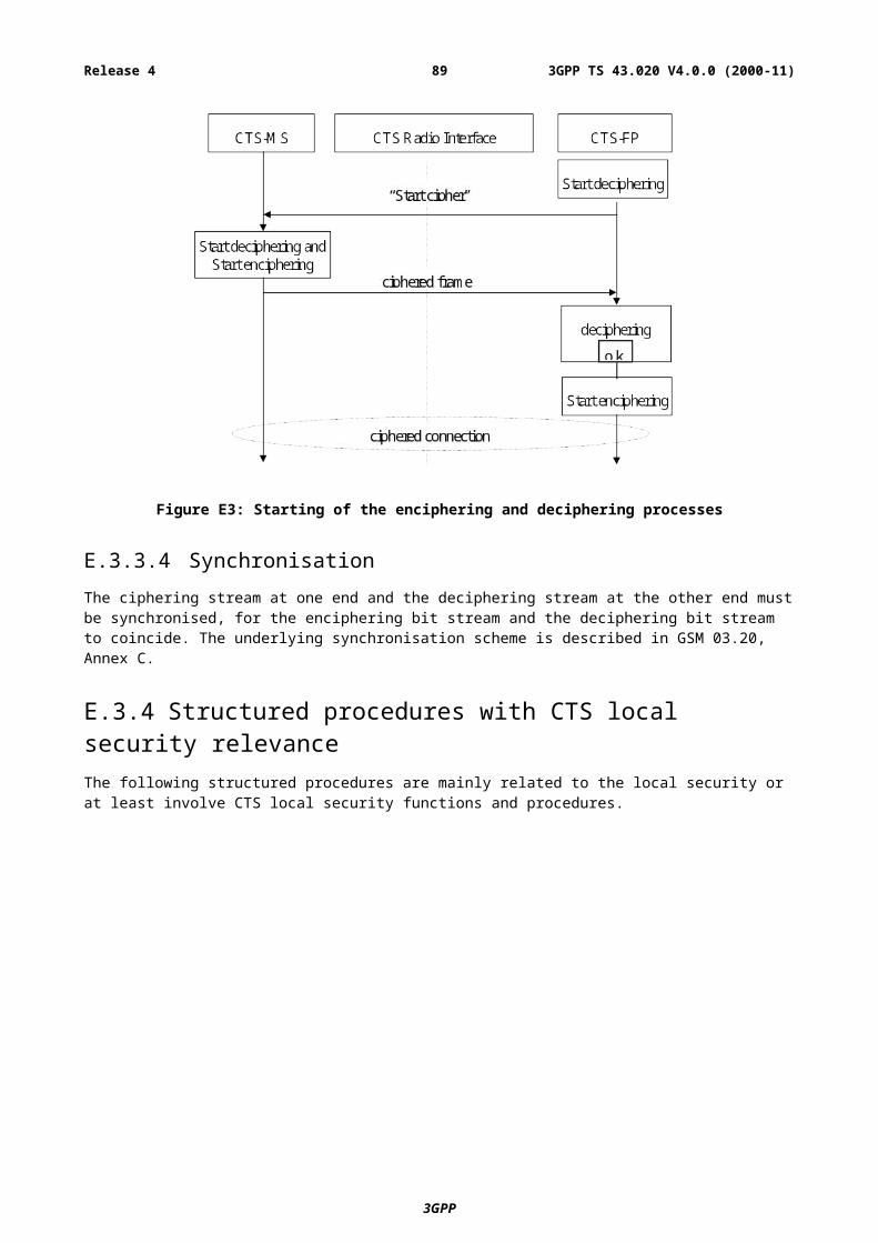
E.6.1.2 Changing of IFPEI Each, CTS-FPE contains an identity (IFPEI).The IFPEI can be used (associated to the IFPSI) for local security and network security procedures. The Fixed Part Equipment is uniquely defined by the IFPEI. The IFPEI is stored in a secure way in accordance with the requirements for storage of the IMEI as described in GSM 02.09.
E.6.1.3 Changing of IFPSI and operator and subscription related keys (KiFP, KOP)These values are stored in the FP-SIM; the IFPSI can only be read and not updated while the operator and the subscription related keys are used in the FP-SIM and cannot be accessed.
E.6.1.4 Changing of timers and timer limitsThe CTS-FP operation is partially under control of timers. When timer values are stored in E2PROM memory there should be a protection against malicious reprogramming. The use of external timer hardware should only be allowed when accompanied with comprehensive protection countermeasures.
E.6.1.5 Changing of radio usage parametersThis annex defines mechanisms to protect the parameters that will set the radio usage characteristics during transport to the local CTS system. In addition these parameters should be protected when stored inside the CTS-FPE.
E.6.2 Protection and storage mechanismsIn this subclause some basic approaches for realising CTS-FP integrity mechanisms are described. The mechanisms are divided into three groups. One group targets the protection of data that is stored
In a static or semi-static way in re-programmable non-volatile memory. The second group targets timer values that change frequently. A third group targets physical protection aspects.
E.6.2.1 Static or semi static valuesData that is stored permanently or changes seldomly are either stored on the FP-SIM (KOP,, KiFP, IFPSI), or might be stored in write-once memory cells (Ka), the place of storage could be defined. Thus some form of physical security is necessary. Furthermore, specific standards in term of technology (e.g. NIST FIPS1-40-1) can be used.
E.6.2.2 TimersIf timer stored values can be accessed (e.g. when they are stored in physically accessible E2PROM) they can be protected in the same spirit as static data but the mechanism should be tailored for frequent update of the values to be protected. Alternatively, these values could be stored in the main processor chip.
E.6.2.3 Physical protectionPhysical protection should prevent that it being easy to reprogram (flash) memory with CTS-FP system software through direct physical access to the memory chip or the physical exchange critical hardware components. It should also protect electrical sensing mechanisms against obvious attacks, e.g., by resetting components.
E.7 Type approval issuesThe test houses cannot perform a security evaluation of a CTS-FP to verify if the CTS-FP meets the requirements on security. However, each CTS-FP comes with a set of cryptographic mechanisms that may effect ordinary type approval procedures. There should be no bypass mechanisms to critical security mechanisms for such type approval procedures.
3GPP
3GPP TS 43.020 V4.0.0 (2000-11)89Release 4
E.8 Security information to be stored in the entities of the CTS
This clause gives an overview of the security related information and the places where this information is stored in the CTS.
The entities of the CTS where security information is stored are:
- CTS home location register (CTS-HLR);
- CTS service node (CTS-SN);
- CTS authentication centre (CTS-AuC);
- CTS fixed part equipment (CTS-FPE);
- FP-SIM card;
- CTS mobile equipment (CTS-ME);
- MS-SIM card.
E.8.1 Entities and security information
E.8.1.1 CTS-HLRThe CTS-HLR stores permanently:
- The IFPSI;
- The authentication key KiFP.
The CTS-HLR receives and stores (possibly after processing):
- The mobile equipment identity IMEI;
- The IFPEI.
E.8.1.2 CTS-SNThe CTS-SN receives and stores possibly after processing:
- KOP associated to a given IFPSI;
- Subscription timers;
- RAND value associated to an authentication and key generation procedure;
- SRES the result of the authentication procedure;
- The B5, B6 algorithms.
E.8.1.3 CTS-AuCIn the CTS authentication centre are implemented:
- The authentication algorithm A3;
- The key generation algorithm A8.
3GPP
3GPP TS 43.020 V4.0.0 (2000-11)90Release 4
E.8.1.4 CTS Fixed Part Equipment (CTS-FPE)The CTS-FPE stores permanently:
- The encryption algorithm A5/2.
The CTS-FPE generates and stores:
- The CTS authentication key Ka;
- The CTSMSI;
- The ciphering key Kc.
The CTS-FPE receives and stores (possibly after processing):
- The mobile equipment identity IMEI;
- The IMSI.
The CTS-FPE stores for each CTS-MS/CTS-FP pair a record of data which is needed for access on the CTS Radio Interface. The records are stored as a linear fixed file (see GSM 11.11) and contain:
- The authentication key Ka;
- The CTSMSI;
- The IMSI;
- Other, non security relevant information, which are related to a CTS-MS/CTS-FP pair.
The structure of the linear fixed file is shown in figure E11:
Index(Record Number)
Linear fixed file with one record for each CTS-MS/CTS-FP pair(Read/Write)
1 Ka[1], CTSMSI[1], IMSI[1], other data [1]2 Ka[2], CTSMSI[2], IMSI[2], other data [2]. .. .N Ka[n], CTSMSI[n], IMSI[n], other data [n]
Figure E11: Storage of CTS-MS/CTS-FP pair related data on the CTS-FPE
The number of records is defined at subscription time and thus determines the number of CTS-FP, a CTS-MS can be enrolled to.
E.8.1.5 Fixed Part SIM card (FP-SIM)The FP-SIM includes specific information for CTS purpose.
- The IFPSI;
- The KiFP;
- The KOP;
- The list of PLMNs whose subscriber can roam onto the CTS-FP.
E.8.1.6 CTS Mobile Equipment (CTS-ME)
E.8.1.7 Mobile Station SIM card (MS-SIM)The MS-SIM is a normal GSM SIM card as defined in GSM 11.11 that includes any information for CTS purpose.
3GPP
3GPP TS 43.020 V4.0.0 (2000-11)91Release 4
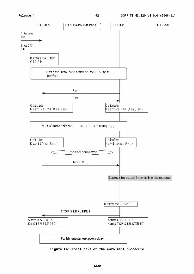
The MS-SIM stores for each CTS-MS/CTS-FP pair a record of data which is needed for access on the CTS Radio Interface. The records are stored as a linear fixed file (see GSM 11.11) and contain:
- the authentication key Ka;
- the CTSMSI;
- the IFPEI;
- other, non security relevant information, which related to a CTS-MS/CTS-FP pair.
The structure of the linear fixed file is shown in the figure E12.
Index(Record Number)
Linear fixed file with one record for each CTS-MS/CTS-FP pair(Read/Write)
1 Ka[1], CTSMSI[1], IFPEI[1], IFPSI[1],other data [1]2 Ka[2], CTSMSI[2], IFPEI[2], IFPSI[2],other data [2]. .. .N Ka[n], CTSMSI[n], IFPEI[n], IFPSI[n], other data [n]
Figure E12: Storage of CTS-MS/CTS-FP pair related data on the CTS-ME
The number of records is definedby the mobile manufacturer and thus determines the number of CTS-FP, a CTS-MS can enroll onto.
E.9 External specification of security related algorithmsThis annex specifies the cryptological algorithms and algorithms which are needed to provide the various security features and mechanisms defined in the CTS service description.
The following algorithms are considered;
- Algorithm A5/2: Ciphering/deciphering algorithm;
- Algorithm B1: Ciphering key generation algorithm
- Algorithm B2: Authentication key generation algorithm
- Algorithm B3: Authentication algorithm
- Algorithm B4: Authentication algorithm
- Algorithm B5: Message authentication algorithm used for CTS-FP authentication
- Algorithm B6: Message authentication algorithm used for signature authentication
The A5/2 is specified in GSM 03.20 Annex C.
The external specification of the algorithms B1, B2, B3, B4, B5, B6 is defined below. The internal specification is managed by SAGE.
E.9.1 Algorithm B1
E.9.1.1 PurposeThe B1 algorithm is used to generate the ciphering key Kc from the two random challenges CH1 and the authentication key Ka which is derived from Ka.
Location: CTS-ME, CTS-FPE
3GPP
3GPP TS 43.020 V4.0.0 (2000-11)92Release 4
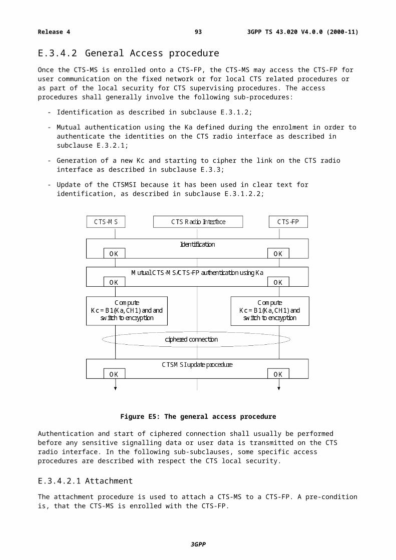
E.9.1.2 Implementation and operational requirementsThe two input parameters Ka, CH1 and the output parameter Kc of the algorithm shall use the following formats:
Figure E13: The ciphering key generator B1
- Input 1: Bit string of length |Ka| = 128 bits;
- Input 2: Bit string of length |CH1| = 128 bits;
- Output: Bit string of length |Kc| = 64 bits.
The calculation time of B1 shall not exceed 200 ms.
E.9.2 Algorithm B2
E.9.2.1 PurposeThe algorithm B2 is used to generate:
- The authentication key Ka;
- The initial authentication key. This authentication key generation and usage is part of the initialisation method using the CTS Radio Interface.
Location: CTS-ME, CTS-FPE
E.9.2.2 Implementation and operational requirementsThe three input parameters FPAC , RIMS , RIFP, and the output parameterKa of the algorithm shall use the following formats:
Figure E14: The key generation algorithm B2
- Input 1: Bit string of length |FPAC| respective bit string of length |FPAC| = 128 bit;
- Input 2: Bit string of length |RIMS| respective bit string of length |RIMS| = 64 bit;
- Input 3: Bit string of length |RIFP| respective bit string of length |RIFP| = 64 bit;
- Output: Bit string of length |Ka| = 128 bit.
3GPP
3GPP TS 43.020 V4.0.0 (2000-11)93Release 4
The calculation time of the B2 algorithm shall not exceed 250 ms.
E.9.3 Algorithms B3 and B4
E.9.3.1 PurposeThe B3 and B4 algorithms are used to perform the mutual authentication via a challenge-response scheme.
Location: CTS-ME, CTS-FPE.
E.9.3.2 Implementation and operational requirementsThe two input parameters Ka and CH1 respective CH2 and the output parameter (X)RES1 respective (X)RES2 of the algorithm shall use the following formats:
Figure E15: The response generation by B3 and B4
- Input 1: Bit string of length |Ka| = 128 bit;
- Input 2: Bit string of length |CH1| respective bit string of length |CH2| = 128 bit;
- Output: Bit string of length |(X)RESP1| respective bit string of length |(X)RESP2| = 128 bit.
The calculation time of B3 respective B4 shall not exceed 200ms for one operation.
E.9.4 Algorithms B5 and B6
E.9.4.1 PurposeThe B5 algorithm is used to perform CTS-FP authentication by the CTS-SN.
The B6 algorithm is used by the CTS-FP to authenticate the signature issued by the CTS-SN.
Location: CTS-FPE, CTS-SN.
E.9.4.2 Implementation and operational requirementsThe two input parameters Kop and Data1 respective Data2 and the output parameter MAC1 respective MAC2 of the algorithm shall use the following formats:
Figure E16: The response generation by B5 and B6
3GPP
3GPP TS 43.020 V4.0.0 (2000-11)94Release 4
- Input 1: Bit string of length |Kop| = 128 bit;
- Input 2: Bit string of length |Data1| respective bit string of length |Data2| = n octets;
- Output: Bit string of length |MAC1| respective bit string of length |MAC2| = 64 bit.
E.10 Coding of the FPAC and CTS-PINThe CTS-PIN is a local product key. It is initialised at manufacturer customisation.
At CTS-FP reset, the PIN code value returns to initial manufacturer value.. The CTS-PIN can be modified by the user; a pre-condition is to enter the old CTS-PIN. When remote MMI is used, attachment is performed on the MS/FP interface.
The CTS-PIN cannot be de-activated.
The number of tries is infinite and no blocking mechanism is applied.
The FPAC is coded in 128 bits.
The CTS-PIN is entered by the user of the CTS on the CTS-MS respective on the CTS-FP. The CTS-PIN is presented as a BCD number of decimal digits (0 - 9), each digit coded in four bits.
The number of digits of the CTS-PIN is 8.
The CTS-PIN is copied to the FPAC in order to perform the procedures for checking the CTS-PIN entered by the user. As the number of digits of the CTS-PIN is less than 32, the CTS-ME respective the CTS-FP shall pad the unused digits with « F » (hexadecimal presentation of 16) before it is copied to the FPAC.
E.11 (informative annex): Guidelines for generation of random numbers
Both the CTS-MS and the CTS-FP must on occasions generate « random » numbers as inputs to security algorithms. Specifically:
the 128-bit input CH1 to the algorithms B1 and B3 is generated by the CTS-FP;
the 128-bit input CH2 to the algorithms B4 is generated by the CTS-MS;
the 64-bit input RIFP to the algorithm B2 is generated by the CTS-FP;
the 64-bit input RIMS to the algorithm B2 is generated by the CTS-MS;
This section indicates the requirements on the « randomness » of these values. There are essentially two requirements: non-repetition (for CH1 to CH2, which are the generated many times) and unpredictability.
Non-repetition of CH1 and CH2: The probability that a new value CH1 (or CH2) is the same as any one particular previously generated value of CH1 (or CH2) should not be significantly greater than 2-128 . It is assumed that the number of values of CH1 (or CH2) generated by any CTS-FP will be much less than 2-128.
Unpredictability of CH1 and CH2: It is not necessary for every new CH1 (or CH2) to be « completely random », i.e. to be exactly likely to assume any possible value, independent of all previously generated values. However, the generation must not be easily predictable. Given all previously generated values of the CH1 (or CH2), the probability that a newly generated CH1 (or CH2) will assume any specific value should not be greater than 2-32.
Unpredictability of RIFP and RIMS: The probability that RIFP (or RIMS) will assume any specific value should be not greater than 2-32.
3GPP
3GPP TS 43.020 V4.0.0 (2000-11)95Release 4
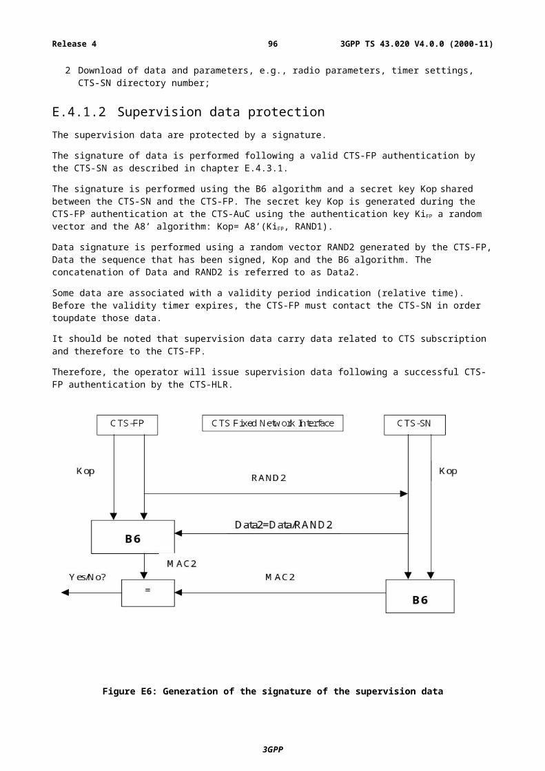
Annex F (informative):Change History
Change historyDate TSG # TSG
Doc.CR Rev Subject/Comment Cat Old New
Release 92 Last common Phase 1/Phase 2 version 3.3.2Aug 1992 SMG#03 016 Working version 4 D 3.3.2 4.0.0Aug 1992 SMG#03 011 2 B 3.3.2 4.0.0Aug 1992 SMG#03 013 2 B 3.3.2 4.0.0Aug 1992 SMG#03 014 C 3.3.2 4.0.0Oct 1992 SMG#04 015 2 C 4.0.0 4.1.0Jan 1993 SMG#05 017 1 Titles of annexes are added from version 3.3.0.
Annexes are renamed to annex A, B and C (PNE!).Some figures in section 2 are renumbered.
D 4.1.0 4.2.0
June 1993 SMG#07 022 D 4.2.0 4.2.1Oct 1993 - - - TS changed to prETS 300 534 - 4.2.1 4.2.2Apr 1994 SMG#10 024 1 F 4.2.2 4.3.0Apr 1994 SMG#10 025 F 4.2.2 4.3.0Apr 1994 SMG#10 TS frozen for Phase 2 by SMG#10 4.3.0Sept 1994 - - - ETS 300 534 1st edition - 4.3.0 4.3.1Feb 1996 SMG#17 157/96 A001 Length of ciphering key Kc for signalling and testing
purposesD 4.3.1 4.3.2
Feb 1996 - - - ETS 300 534 2nd edition Last common Phase 2/Phase 2+ version
- 4.3.2 4.3.3
Dec 1996 - - - GTS converted to draft prETR 300 929 for Release 96 - 4.3.3 5.0.0- - - ETS 300 929 first edition - 5.0.0 5.0.1
Feb 1997 SMG#21 132/97 A002 4 Definition of ciphering for HSCSD F 5.0.0 5.1.0Feb 1997 SMG#21 181/97 A004 1 Ciphering Algorithm(s) support (phase 2+) A 5.0.0 5.1.0
- - - ETS 300 929 second edition - 5.1.0 5.1.1Oct 1997 SMG#23 97-778 A006 1 (GPRS Release 97) B 5.1.1 5.2.0Oct 1997 SMG#23 97-778 A007 1 (GPRS Release 97) B 5.1.1 5.2.0Mar 1998 - - - ETS converted to version 6.0.0 because of GPRS
Release 97 contents.- 5.2.0 6.0.0
July 1998 - - - Specification published as TS 100 929 - 6.0.0 6.0.1Feb 1999 SMG#28 P-99-117 A010 CTS Release 98
New annex E related to CTS securityB 6.0.1 7.0.0
July 1999 SMG#29 P-99-530 A013 CTS R98: Introduction of CTS-FP authentication and signature generation by CTS-SN
B 7.0.0 7.1.0
July 1999 SMG#29 P-99-530 A014 CTS R98: CTS Security functions in case of license exempt frequencies
F 7.0.0 7.1.0
July 1999 SMG#29 P-99-553 A016 4 Correction of the handling of the Ciphering Key Sequence Number (CKSN)
F 7.0.0 7.1.0
Oct 1999 SMG#30 P-99-743 A018 Clarification on security triplet re-use conditions F 7.1.0 8.0.0Oct 1999 SMG#30 P-99-743 A017 Introduction of EDGE variant of A5 algorithm B 7.1.0 8.0.0Mar 2000 SMG#32 P-00-309 A023 GPRS Ciphering algorithm negotiation A 8.0.0 8.1.0Oct 2000 - - - Updated to 3GPP TS Format: 3GPP TS 03.20 version 8.1.0 - 8.0.0 8.1.0Oct 2000 SMG#32 P-00-309 A024 GPRS Ciphering algorithm negotiation
SMG#32 Decision to apply this CR to Release 1999 and create Release 2000 (version 9.0.0 not created, see below)
A 8.0.0 9.0.0
Nov 2000 - - - - Transferred to 3GPP as 3GPP TS 43.020 version 4.0.0 (Release 4)
- 9.0.0 4.0.0
3GPP
3GPP TS 43.020 V4.0.0 (2000-11)96Release 4