Embed Size (px)
Citation preview

OWNERSMANUAL
MODEL NO.917.255915
Caution:Read Rules for
Safe Operationand Instruction s
Carefully
GT 18 TWIN
6 SPEED
GARDEN TRACTOR
AssemblyInstallationOperationRepair Parts
anot
her
free
man
ual f
rom
ww
w.s
ears
trac
torm
anua
ls.c
om

CONGRATULATIONS on your purchase of a Sears GT 18-Garden Tractor It has been designed, engineered and manu-factured to give you dependability and performance° Shouldyou experience any problem you cannot easify remedy,please contact your nearest Sears Service Center. They havecompetent, welt-trained technicians and the proper' tools andparts to service or repair this unit
Please read and retain this manual. The instructions wilt enableyou to assemble, operate and maintain your Tractor proper-ly. Afways observe the "RULES FOR SAFE OPERATION _J
YOUR NEW GT 18
GA RDEN TRACTOR
FEATURES...
CRAFTSMAN 18 HP. TWIN-CYLINDER ENGINE.-coot..running performance and long life with ptenty of power totake on a variety of yard, gardening or snow removal tasks.
INTERLOCK SWITCH SYSTEM--allows engine to start onlywhen tractor Clutch-Brake Pedal is depressed and AttachmentClutch Switch is in "OFF H position
ALL GEAR TRANSMISSION-six speeds forward, two reversespeeds-..to let you select the proper match for the terrain andthe job Automotive-type differential helps guard against turfscuffing.
CONTROL PANEL-with Throttle Choke, Light Switch. Ig-nition Switch, Ammeter, Parking Brake Lever and ClutchSwitch--conveniently grouped for ease of use
MODELNUMBERSERIALNUMBER
THE MODEL AND SERIAL NUMBERS WILL BEFOUND ON THE MODEL PLATE ATTACHEDTO THE FENDER_
YOU SHOULD RECORD BOTH MODEL ANDSERIAL NUMBERS AND KEEP IN A SAFE PLACEFOR FUTURE REFERENCE
ATTACHMENT VERSATtLITY..-handtes a large variety ofSears Yard and Garden Tractor Attachments including
44 iNCH MOWER with three "high.lift" blades to standgrass up for level cutsOTHER SOIL TILLAGE ATTACHMENTS including Ptow.Disc Harrow, Drag Harrow and Cultivator46 INCH DOZER BLADE levels or moves dirt and gravel orremoves snow.40 INCH SNOW BLOWER handles wet, heavy powderysnow with easeREAR GRADER AND LEVELER BLADE leve_s newyards, grading lanes, driveways and parking areas,
LIMITED TWO YEAR WARRANTY
ON ELECTRIC 5TART RIDING EQUIPMENT
For two years from date of purchase, when this riding equipment ismaintained, lubricated, and tuned up according to theoperating and maintenance instructions in the owner s manual, Sears wilt repair free of charge any defect in material or
workmanship in this electric start riding equipment__2
This warranty excludes blade(s), blade adapter(s), spark plug(s), air deanm (s) and belt(s), which a_e expendable and be..
come worn during normaI use,_2
This warranty does not cover:
- tire replacement or _epair caused by punctures from outside objects (such as nails I:horns. stumps, o_ glass};and
,, repairs necessary because of operator abuse or negligence, incIuding the failure to maintain the equipment
according to instructions contained in the owner's manual; and f_
.. riding equipment used for commercial or rental purposes
FULL 90-DAY WARRANTY ON BATTERY
For 90 days from the date of purchase, if any battery included with this riding equipment proves defective in materia$ ol
workmanship and our testing determines the battery wilt not hoid a charge, Sears will replace the battery at no charge, _x_2
WARRANTY SERVICE IS AVAILABLE BY CONTACTING THE NEAREST SEARS SERVICE CENTER/DEPART-
MENT IN THE UNITED STATES. This warranty applies only while this product is in use in the United States
This warranty gives you specific legal rights_ and you may also have other rights which vary from state to state
Sears, Roebuck and Co., D/698-731A, Sears Tower, Chicago, tL 60684 _,
anot
her
free
man
ual f
rom
ww
w.s
ears
trac
torm
anua
ls.c
om

TABLE OFRULES FOR SAFE OPERATION ........ BELOW
ASSEMBLY INSTRUCTIONS ................. 4
OPERATION INSTRUCTIONS ................ 7
CONTENTSMAINTENANCE INSTRUCTIONS ............. 13
TROUBLE SHOOTING ..................... 25
REPAIR PARTS ............................. 27
RULES FOR SAFE OPERATION1,, Know the controls and how to stop quickly. READ THIS
OPERATOR'S MANUAL and instructions furnishedwith attachments°
2. Do not allow children to operate the machine. Do notallow adults to operate it without proper instruction,
3. Do not carry passengers° Do not mow when children endothers are around.
4. Always wear substantial footwear,. Do not wear loose fittingclothing that could get caught in moving parts,
5_ Keep your eyes and mnd on your tractor, mower and thearea being cut.. Don t let other interests dtstract you,
6<, Do not attempt to operate your tractor or mower whennot in the drivers seat.
7, Always get on or off your tractor from the operators lefthand side.
8. Clear the work area of objects (wire, rocks, etc,,) whichmight be picke d up and thrown.
9, Disengage all attachment clutches before attempting tostart the engine.
1Q, Disengage power to attachments and stop the engine be-fore leaving the operator s position.
11o Disengage power to mower, stop the engine and disconnectspark plug wire(s) from spark plug(s) before cleaning, mak-ing an adjustment or repairs,
12, Disengage power to attachments when transporting or notin use,
13o Take all possible precautions when leaving the vehicle un-attended. Disengage the power-take-off, lower the attach-ments, return drive control lever to neutral, shift intoneutral, set the parking brake, stop the engine and removethe key,,
14., Do not stop or start suddenly when going uphitl or down-hill Mow up and down the face of slopes (not greater than15°); never across the face Refer to page 47,
15,, Reduce speed on slopes and make turns gradually to pro.vent tipping or loss of control, Exercise extreme cautionwhen changing direction on slopes
16 While going up or down slopes, place Gear Shift ControlLever in Ist gear and Range Shift Lever in 'LO (Low)position to negotiate the slope without stopping,
17, Never mow in wet or slippery grass, when traction is un _sure or at a speed which could cause a skid,
18. Stay alert for holes in the terrain and other hidden hazards.,Keep away from drop-offs°
19. Do not drive too close to creeks, ditches and public high-ways.,
20+, Exercise special care when mowing around fixed objectsin order to prevent the blades from striking them_ Never
deliberately run tractor or mower into or over any foreignobject_
21,, Never shift gears until tractor comes to a stop_22. Never place hands or feet under the mower, in discharge
chute or near any moving parts while tractor ormower arerunning,, Always keep clear of discharge chute.
23. Use care when pulling loads or using heavy equipment,a. Use only approved drawbar hitch points.b., Limit loads to those you can safely control,c. [)o not turn sharply, Use care when backing.,d., Use counterweight or wheel weights when suggested in
the owner s manual24. Watch out for traffic when crossing or near roadways,25_ When using any attachments, never direct discharge of
material toward bystanders nor allow anyone near the ve-hicle while in operation.,
26° Handle gasoline with care- it is highly flammable°a. Use approved gasoline containers°b. Never remove the fuel cap of the fuel tank or add gas-
oline to a running or hot engine or an engine that hasnot been allowed to cool for several minutes after run-ning. Never fill the tank indoors, always clean up spilledgasoline.
c. Open doors if the engine is run in the garage - exhaustfumes are dangerous° Do not run the engine indoors°
27° Keep the vehicle and attachments in good operating con-dition, and keep safety devices in place and working.
28,, Keep all nuts, bolts and screws tight to be sure l_he equip-ment is in safe working condition°
29,, Never store the equipment with gasoline in the tank insidea building where fumes may reach an open flame or sparkAllow the engine to cool before storing in any enclosure.
30,, To reduce fire hazard, keep the engine free of grass, leavesor excessive grease_ Do not clean product while engine isrunning.
31, Except for adjustment; DO NOT operate Engine if aircleaner or cover directly over carburetor air intake is re-moved. Removal of such part could create a fire hazard,,
32. Do not operate without a muffler or tamper with the ex-haust system, Damaged mufflers or spark arresters couldcreate a fire hazard. Inspect periodically and replace ifnecessary.
33 The vehicle and attachments should be stopped and in-spected for damage after striking a foreign object and thedamage should be repaired before restarting and operatingthe equipment.
34° Do not change the engine governor settings or overspeedthe engine; severe damage or injury may result
35° When using the vehicle with mower, proceed as follows:a. Mow only in daylight or in good artificial lightrbo Shut the engine off when unclogging chute.c. Check the blade mounting bolts for proper tightness at
frequent intervals,36 Do not operate the mower without the deflector shield in
place.,37. Disengage power to mower before backing up,, Do not mow
in reverse unless absolutely necessary and then only aftercareful observation of the entire area behind the mower.
38. Under normal usage the grass catcher bagm_aterial is stib_tto deterioration and wear. It should be checked frequentlyfor bag replacement. Replacement bags should be checkedto ensure compliance with the original manufacturer'srecommendations or Sl_ecifications.
LOOK FOR THIS SYMBOL TO POINT OUT IMPORTANT SAFETYPRECAUTIONS. IT MEANS - ATTENTION! BECOME ALERTIYOUR SAFETY IS INVOLVED°
WARNING
This unit is equipped with an internal combustion engine and should not be used on or near any unimproved forest-covered, brushcovered or grass-covered land unless the engine s exhaust system is equipped with a spark arrester meeting applicable local or statetaws (if any) If a spark arrester is used, it should be maintained ;n effective working order by the operator
In the State of California the above is required by taw (Section 4442 of the California Public Resources CodeL Other states may
have similar laws. Federal laws apply on federal lands. S_e your Authorized Service Center for spark arrester muffler part number_4A_0,
anot
her
free
man
ual f
rom
ww
w.s
ears
trac
torm
anua
ls.c
om

CUT AWAY VIEW
F IG Ut_E 1
BATTERYCOMPARTMENT
FIGURE 2
FIGURE 3
VENT CAP
BATTERYTUBE
BATTERYCELL
HOOD
GRILL
HEXBOLTS
BLACK(NEGATIVE)CABLE
ASSEMBLYTo assemble and adjust your Tractor you wilt need:two 7/16" wrenches, one 9/16" wrench and a utility
knifeNOTE: RIGHT+lAND (R.H.) AND LEFT HAND (Loll.) AREDETERMINED FROM OPERATOR'S POSITION WHILESEATED ON THE TRACTOR,
1 Remove Battery, Steering Wheel, Seat and Bag of Parts,. Cut downfour comers of carton with utility knife, and fold down carton sides,,Remove Banding holding Mower Deck in place and lower Deck downto the floor. Turn the Deck over so the Blades are down. Disengagethe Parking Brake and roll the Tractor off the skid Be careful that youdo not step on or roll the Tractor over any carton staples
READ THE INSTRUCTIONS INCLUDED WITHTHE BATTERY ACID CONTAINER. ALWAYSWEAR GLOVES, CLOTHING AND GOGGLES TO
PROTECT YOUR HANDS, SKIN AND EYES.WASH HANDS OR CLOTHING IMMEDIATELY IFACCIDENTALLY IN CONTACT WITHELECTROLYTE,
DO NOT SMOKE, FUMES FROM CHARGEDELECTROLYTE ARE EXPLOSIVE,
t_ill and charge Battery (before installing), "NOTE: SEI_DETAILED INSTRUCTIONS PACKAGED WITH BAT-TERY VENT CAPS IN BAG OF PARTS.a, Fil! Battery with electrolyte to bottoms of tubes in cells
(Fig, 1) NOTE: DO NOT OVERFILL. OVERFILLINGWILL RESULT IN DAMAGE TO TRACTOR
b,_ Check level of electrolyte after 30 minutes. Add addi-tional electrolyte if necessary° I_OTE: TIGHTEN VENTCAPS SECURELY,
c_ Charge Battery at a rate of 6 amperes for' one hour,d, Neutralize excess electrolyte for disposal by adding it
to four inches of water in a five gallon plastic container,Stir with a wooden or plastic paddle while adding bak-ing soda until the addition of more soda causes no morefoaming. ..
DO NOT SHORT BATTERY TERMINALS,
BEFORE INSTALLING BATTERY, RE-MOVE METAL BRACELETS, WRIST-WATCH BANDS, RINGS, ETCo FROMYOUR PERSON.
3 Install Battery,a. L_ift hood from rear sides (Fig, 2)b, Remove tape from Plastic Tray, Make sure Drain Tube
(Fig,, 3) is fastened to Drain Hole in Battery Tray andBattery Tray is positioned in hole of Battery Support,
c. P_taceBattery in Plastic Tray (Battery Terminals to frontof Tractor ) (Fig., 3)
4,_ Connect Battery Cables using: two Hex Botts, two FiatWashers, two Lockwashers and two Hex Nuts (shown fullsize below) found in Bag of Parts,
('1 .... Qu[IIl l/lllIllIIll
POSITIVE TERMINAL MUST BE CON-NECTED FIRST TO PREVENT SPARKSFROM ACCIDENTAL GROUNDING.
a, Connect RED Battery Cable to Positive (+) Battery Ter =minal with Hex Bolt, Flat Washer, Lockwasher and HexNut (Fig° 3). Tighten securely.
b_ Connect BLACK Ground Cable to Negative (.) BatteryTerminal with remaining Hex Bolt, Flat Washer, Lock.washcr and Hex Nut (Fig,, 3), Tighten securely.
anot
her
free
man
ual f
rom
ww
w.s
ears
trac
torm
anua
ls.c
om

_. tnstalfBatteryusing:twoInt,/Ekt,Lockwashers, two WingNuts (shown full size below) and
two Battery Bolts and one Terminal Guard found in Bag ofParts.
a, Using the square hole on one side of the Battery Support(Fig, 4_ insert one Battery Bolt, head of Bolt down,Fasten the Battery Bolt to the Terminal Guard usingtnto!Ext, Lockwasher and Wing Nut as shown in Fig_ 4,
b Assemble the remaining Battery Bolt to other side ofBattery Support and fasten Terminal Guard to it with reomaining Int,iExt Lockwasher and Wing Nut, TightenWing Nuts securely by hand (Fig,, 4}.
NOTE: USE TERMINAL ACCESS DOORS (FIGo 4) FOR:1 Inspection for secure connedtions (tighten hardware),2, Inspection for corrosion,3, Testing battery,4 Jumping (if required).5_ Charging (if required),
WHEN NOT IN USE, KEEP TERMINALACCESS DOORS CLOSED.
DO NOT START ENGINE UNTIL MOWERSUSPENSION BRACKET HAS BEEN RE-LEASED, SEE MOWER AND DRIVE BELTINSTALLATION, PAGE 8.
6= Remove plastic on Tractor Hood.7., Close Hood,,
8., Install Steering Wheel.NOTE; POSITION FRONT WHEELS FORWARD,a, Remove Hex Bolt, Lockwasher and 2- 3/8 _t Dia Washer
from Steering Column (Fig. 5),bo Position Steering Wheel over Steering Wheel Insert_co Secure Steering Wheel to Steering Column using Hex
Bolt, Lockwasher and 2- 3/8" Dia. Washer (Fig 5),d Snap Steering Wheel Cap in place on Steering Wheel.,
Steering WheeJ Cap found in Bag of Parts,9., Install Seat,,
a Remove cardboard from Seat Pan,,
b o Place Seat on Seat Pan° Screw Adjustment Bolts,Lockwashers and Flat Washers into Seat (Fig,, 6), Ad-justment Bolts, Lockwashers and Flat Washers foundin Bag of Parts. Tighten finger tight°
c. Place Seat in operating position,, Sit on the Seat andpress Clutch-Brake Pedal all the way down,, If operatingposition is not comfortable, adjust Seat.,
d, Raise Seat. Use 9/16" wrench to loosen AdjustmentBolts (Fig 6L When adjusted for comfortable operation,tighten Adjustment Bolts securely,,
INTJEXT,LOCKWASHER
WINGNUT
WING NUT
INT,/EXT;=R
NALACCESSDOOR
TERMINALGUARD
TERMINALACCESS DOOR
BATTERY BOLT
BATTERYSUPPORT
FIGURE 4
STEERING WHEEL CAP
._" 2. 3/B" DIA WASHER
EERtNG WHEEL
_ _---_STEERING WHEEL INSERT
_ _ERING COLUMN
SEAT SEAT
SEAT SWITCH
ADJUSTMENTBOLTS
\FUELTANKCAP
'FIGURE 6
.5 _
anot
her
free
man
ual f
rom
ww
w.s
ears
trac
torm
anua
ls.c
om

FtGURE 7
ENG INE
DIPSTICK
REC(_MMENDED SAE VISCOSITY GRADES
TEMPERATURE RANGE EXPECTED BEFORE NEXT OILCHANGE° ALL OILS MUST MEET A.PJ,. SERVICE CLAS-SIFICATION SD, SE, OR 5F_
-20° 0° 32 ° 60° 80° 100°
30 OR 10W-30 ..............11II1TO AVOID DAMAGE TO THE STARTINGSYSTEM, USE SAE 5W30 OIL WHENTHE TEMPERATURE FALLS BELOW 32O,
' A _ ,,PARKING BRAKE' CLUTCH/BR KE" "_"ENGAGED" POSITION
"C UTCH",O IT,O,\'ARKING°,AK
Capacity is 1 - 112 quarts, NOTE: DO NOT OVERFILL,.Dipstick assembly must be securely tightened into tube atall timeswhen engine is operating.
2. FIll Fuel Tank {Fig 6). Use fresh, dean, regular unleadedautomotive gasoline, (Use of leaded gasoline will increasecarbon and lead oxide deposits and reduce valve life}.Capacity is 3 = 1/2 gallons
FIGURE 8FILL TO BOTTOM OF GAS TANK FILL-ER NECK. DO NOT OVERFILL WIPEOFF ANY SPILLED OIL OR FUEL. DONOT STORE, SPILL OR USE GASOLINENEAR AN OPEN FLAMECLUTCH SWITCH -
GNITION 3.. Tire pressure to 14 PSi in front and 10 PSi in rear
LEARN TO START, STOP AND REVERSEYOUR TRACTOR IN A LARGE, OPENAREA°
FIGURE 9
GEAR SHIFTCONTROL LEVER
INITIAL SERVICE
t.. This engine has been shipped filled with oil Check EngineOil Level with Tractor on level ground, Wipe Dipstick(Fig.. 7) clean, screw it n tight for a few seconds, removeand read Oil Level If necessary, add Oil until "FULL tmark is reached.
NOTE: ENGINE IS SHIPPED WITH SUMMER WEIGHT OIL
NOTE: THIS TRACTOR IS EQUIPPED WITH INTERLOCKSWITCHES TO PREVENT STARTING OF THE TRACTORENGINE WHILE THE ATTACHMENT CLUTCH OR THETRACTOR CLUTCH 1S ENGAGED.
IMMEDIATELY REPLACE SWI'I;CHESTHAT ARE NOT IN PROPER WORKINGORDER. DO NOT ATTEMPT TO DEFEATTHE PURPOSE OF THESE SWITCHi=So
1 Place Attachment Clutch Switch in "DISENGAGED"position (Fig,,9_.
2. Push Clutch-Brake Pedal fully into brake position (Fig 8)_
3. Place Gear Shift Control Lever in "N" neutral, star1: posi-tier, and Range Shift Lever in "N" neutral position (Fig.. 9).
anot
her
free
man
ual f
rom
ww
w.s
ears
trac
torm
anua
ls.c
om

4o full L;noke out (Pig. 9_o
5_
6,
Move Throttle Control to middle position (Fig, 9).
Turn Ignition Key to '_START" position until Engine starts(Fig, 9), NOTE; DO NOT RUN STARTER CONTINU-OUSLY FOR MORE THAN FIFTEEN SECONDS PERM1NUTE_ if engine does not start after several attempts,move Throttle Control ?o 'IF" (fast) position, wait a fewminutes and try again,
The first time you start the engine, it will take extra crank-ing time to move fuel from tank to the engine°NOTE: ALLOW ENGINE TO WARM UP FOR A FEW
MINUTES BEFORE ENGAGING CLUTCH OF TRACTOROR ATTACHMENT,
7 When restartin_l a warm engine, move Throttle Control mid-way between _S" (stow) and "F '1 (fast) position. C%okemay not have to be used.
OPERATION
BEFORE DRIVING THE TRACTOR, IN-STALL MOWER OR REMOVE MOWERSUSPENSION BRACKET.
CAUTIONTO AVOID INJURY
I, Read owners manual,2. Know location and function of atl controls,3_ Keep guards, safety shields and switches in p]ace and work-
ing,4. Remove objects that can be thrown by blades.,5. Do not mow when children and others are around,6, Never carry children or passengers,7., Always look behind machine before backing,8. Do not mow where machine can tip or slip.9. If machine stops going uphill, stop blade and back slowly
down,
10= B'e sure blades and engine have stopped before placinghands or feet near the blades,
1t, Remove key when taaving maehine_
TRACTOR OPERATIION
NOTE: THIS TRACTOR IS EQUIPPED WITH AN OPERATORPRESENCE SENSING SWITCH, ANY ATTEMPT BY THEOPERATOR TO LEAVE THE SEAT WITH THE ENGINE RUN-NING AND THE ATTACHMENT CLUTCH ENGAGED WILLSHUT-OFF THE ENGINE.
1_ With engine running and warm, place Throttte Control mid*waybetween S (slow) and (fast) postton,
2. Push Clutct_,Brake Pedal down firmly (Fig 8)., Move GearShift Control Lever to desired gear and Range Shift Leverto "LO" (Low) position (Figr 9).
3, Release Clutch-Brake Pedat SLOWLY to start forwardor rearwarll movement.
4o tf _qround travel is too slow, move Throttle Control to"FtT (fast) position or press Clutch-Brake Pedal and shiftto a different gear,
NOTE: BRING TRACTOR TO COMPLETE STOP BE-FORE SHIFTING GEARS. ALWAYS SELECT AGROUND TRAVEL SPEED THAT WILL SUIT THE TER-RAIN AND THE ATTACHMENT BEING USED,
NEVER PLACE YOUR HANDS OR FEETIN OR UNDER ANY POWERED ATTACH-MENT OR NEAR ANY MOVING PARTWHILE TRACTOR OR ANY POWEREDATTACHMENT IS RUNNING
DO NOT OPERATE THE MOWER WITH-OUT THE DEFLECTOR SHIELD INPLACE
NOTE: A SPARK ARRESTER MUFFLER (PAGE 30) ISAVAILABLE AS AN ACCESSORY PART FOR YOURTRACTOR, CHECK LEGAL REQUIREMENTS IN YOURAREA.
STOPPING YOUR TRACTOR
1., Push Clutch-Brake Pedal into "BRAKE" positiom2,, Place Parking Brake Lever in "ENGAGED" position and
release pressure from Clutch-Brake. Pedal should remainin brake position, NOTE: MAKE SURE PARKING BRAKEWILL HOLD TRACTOR SECURE.
3 Move Shift Control Lever to "NEUTRAL" position,4. Place Attachment Clutch Lever in "DISENGAGED"
position,5 Move Throttle Control to "S" (slow) position,6, Turn ignition Key to "OFF" position, Never use Choke to
stop Engine,
REMOVE KEY WHEN LEAVING TRAC-TOR TO PREVENT UNAUTHORIZEDUSE,
TRANSPORTIING YOUR TRACTOR
For pushing or towing your tractor, place Gear Shift ControlII /1 _ ,
Lever and Range Shift Lever to N neutraf pos=tJon (Fig. 9).NO3_E: DO NOT TOW YOUR TRACTOR FASTER THANSIX MILES PER HOUR,
TRACTOR OPERATOON ON H0aLS
1., Choose the lowest gear BEFORE starting up or down.hills.
DO NOT DRIVE UP OR DOWN HILLS
WITH SLOPES GREATER THAN 15 ° ,AND DO NOT DRIVE ACROSS ANYSLOPE, REFER TO PAGE 47°
2_ AVOID STOPPING OR SHIFTING ON H ILLS,,
a., if slowing is necessary, move Throttle Control Leverto middle position,
LEAVE ENOUGH ROOM WHEN STOP-PING AND STARTING TO ALLOWSLIGHT TRACTOR ROLL DOWNHILL ASCLUTCH-BRAKE PEDAL MOVESTHROUGH CLUTCH POSITION,,
bo If stopping is absolutely necessary, push Clutch-BrakePedal quickly to brake position and engage ParkingBrake.
c. To restart your tractor, make sure tractor is in tst gearand that you have allowed room to roll slightly down-hill, Disengage Parking Brake and release Crutch, BrakePedal SLOWLY to start tractor forward movement.,
7 _ 3- Make all turns slowly
anot
her
free
man
ual f
rom
ww
w.s
ears
trac
torm
anua
ls.c
om

POSITIVE(RED CABLE)TERMINAL
FIGURE 10
FIGURE 11
DEPTHADJUSTMENTKNOB
\
FIGURE 12
NEGATIVE(BLACK CABLE)TERMINAL
_RY
SUSPENSIONBRACKET
ATTACHMENTHANDLE
|GHEST _'POSITION
ATTACHMENTHANDLE
_"LOWEST"POSITION
KET
RELEASE
FRONTSUSPENSIONBRACKET
STARTING YOUR TRACTOR WITHA LOW BATTERY
If your Battery is too low to start the engine, it shouid berecharged_ If "Jumper Cabfes" are used for emergency star-ting follow this procedure: NOTE: YOUR TRACTOR IS EQUIP-PEDWITH A 12 VOLT NEGATIVE GROUNDED SYSTEM, THEOTHER VEHICLE MUST ALSO BE A 12 VOLT NEGATIVEGROUNDED SYSTEM,. NOTE: DO NOT USE TRACTOR TOSTART OTHER VEHICLES+
LEAD-ACID BATTERIES GENERATE EX+PLOSIVE GASES. KEEP SPARKS, FLAME,AND SMOKING MATERIALS AWAYFROM BATTERIES. ALWAYS WEAR EYEPROTECTION AROUND BATTERIES,
2
4,
Connect each end of the RED cable to the POSITtVE (+)terminals of each battery (taking care not to short againstchassis) (Fig,. 10),
Connect one end of the BLACK cable to the NEGATIVE(-) terminal of fully charged battery,
Connect the other end of the cable to the L+H,, Side PanelBolt (Fig. 8),. NOTE: KEEP AWAY FROM GAS TANK ANDBATTERY
Disconnect cables in reverse order:a L H+ Side Panel Bolt (Fig, 8)_b., Negative terminal of fully charged battery.c, Positive terminals.
MOWER AND DRIVE BELT
IN STALLATION
Your tractor has been shipped with the Mower SuspensionBracket banded to the frame, Remove bands and lower Mower
Suspension Bracket (Fig+ 11 )+
MOWER INSTALLATION
1+ Remove banding from Suspension Arms and Gauge WheelsoSet Gauge Wheels aside for later assembly.
2. Slide Mower under Tractor, Deflector to right hand side.
3o Slide Front Suspension Brackets into Mower Brackets, Re-tain with Release Pins (Fig. 12), Turn Depth AdjustmentKnob counterclockwise ( ('-", } until it stops. Push Attach*ment Handle forward to lower mower to ground,
4+ Slide Studs through Lift Links on both sides of Tractor(Fig, 12A)+ Retain with Washers and Retainer Springsfound in Bag of Parts,
5_
6_
Place the Suspension Arms on Brackets on both sides ofFrame (Fig. t2A)+ Retain with Washers and RetainerSprings found in Bag of Paris.
Turn Depth Adjustment Knob (Fig. t2) clockwise ((-_)to remove slack from Mower Suspension+
7. Roll Drive Belt over Primary Mandrel (Fig+ 13)+
8. t_sert Gauge Wheel Bar into Bracket+, Retain with ClevisPin and Retainer Spring (Fig 14),+
-8 + ,,,_
anot
her
free
man
ual f
rom
ww
w.s
ears
trac
torm
anua
ls.c
om

DRIVE BELT INSTALLATION
I. Remove Hood and Gritl (see page 24),
2. Place Mower Drive Belt over Clutch Pulley and under IdlerPulley and Tension Pulley (Fig, 15L NOTE: PULL LEVERUP TO SWING TENSION PULLEY FOR BELT CLEAR-ANCE,, Make sure narrow "V j' side of Belt is engaged witheach Pu{ley,
3, Pull Mower Drive Belt over Front Mower Suspension Brack-et (Fig. 16)o
4o Replace Hood and Grilt,
BELT ADJUSTMENT
1.. Lower mower
2,, If dimension "A" on Idler Bracket Assembly measures I/4"or less, Mower Drive Belt must be adjusted (Fig. 15- insetL
3 Disengage Attachment Clutch Switch,
4. Remove, Bolt, Washer, Washer (2)_ Lockwasher and Nutfrom Idler Pulley (Fig_ 15- inset) (original position),
5. Place V,Belt and Idler Pulley in "NEW" Pulley position(Fig., 15 - inset). Replace Bolt, Washer, Washer (2), Lock-washer and Nut Tighten securely
6. Check V-Bett for proper installation on al! Pulley Grooves
GAUGEWHEELBAR
GAUGEWHEEL
\
CLUTCH
FULLEY_
TENSIONPULLEY
CLEVISPIN
RETAINER
SPRING
BRACKET
FIGURE 14
MOWERORIVEBELT
IDLERILLEY
FIGURE 12A
PRIMARYMANDREL
MOWER DRIVEBELT
IDLER BRACKETASSEMBLY
PULL FORWARD _P'TO LOOSEN BELTFOR EASIERBELT INSTAL LATt ONj_I_"
MOWER SUSPENSIONBRACKET
FIGURE 15
MOWERDRIVE BELT
FIGURE '13 - 9- FIGURE 16
anot
her
free
man
ual f
rom
ww
w.s
ears
trac
torm
anua
ls.c
om

ION
ATTACHMENTHANDLE
MOWER ADJUSTMENT
Adjust the mower' while tractor is parked on levet ground ordriveway, NOTE: MOWER SHOULD BE IN LOWEST CUT-TING POSITION, Make sure tire pressures are 14 PSi in front;10 PSi in teat,,
H,_IRPINCLIP:1
T.,NT............. i----'--
............o ......,,u::.
SIDE TO SIDE ADJUSTMENT
1_ Use a ruler to make sure Flanges at rear of mower deckare the same height from the ground on each side (Fig,t9),
2. If adjustment is required, snap out Access Cover on L,H.side of tractor above Foot Rest (Fig, 18),.
3o Move Attachment Handle to futi "UP" position (Fig 17).
4, To lower tight side of mower, loosen Nut "B" and screwNut "A" down on Adjustment Rod,
5o To lower ieft side of mower, loosen Nut r'B" and screwNut "A" up on Adjustment Rod,
6_ Adjust until both rear mower flanqes are the same heightabove the ground, Tighten Nuts A and B securely.Snap Access Cover in place.
FRONT TO REAR ADJUSTMENT
Move Attachment Handle to futl "UP" positior_ (Fig. 17),After leveling side to side, measure R.Ho Flanges at FRONTAND REAR OF MOWER,. The RH. Front Flange shouldmeasure 3/4" tower than the RH Rear Flange (Fig° 19),
If adjustment is required, follow procedure below.
FIGURE 18
FRONTFLANGE
FLANGEFLANGE
FIGURE .19 o _ _ - - 10 -
anot
her
free
man
ual f
rom
ww
w.s
ears
trac
torm
anua
ls.c
om

;_ IU r,,/_loC rriul_t| Ur |VI_.,IVVr'M
Loosen Nuts "D". Scre+w Nuts _iC" up onto SuspensionArms (Fig. 28). NOTE: SCREW NUTS "C" ON BOTHSUSPENSION ARMS THE SAME NUMBER OF TURNSSO MOWER WILL REMAIN LEVEL Tighten Nuts "D"securely,
2., TO LOWER FRONT OF MOWERLoosen Nuts "C _. Screw Nuts "D" down Suspension Arms,NOTE: SCREW NUTS "D" THE SAME NUMBER OF
TURNS SO MOWER WILL REMAIN LEVEL TightenNuts "C _ securely.,
3o With mower deck at desired height, set Gauge Wheels (Fig_17) to lowest position without touching the ground_
Use Adjustment Handle to set mower at the approximatecutting height you need. Use Clevis Pins (Fig,, t7) to set gaugewheels at lowest point without touching the ground.
MOWER OPERATIONWhen ready to mow, lower Attachment Handle {Fig. 21)to preferred mower height, Select a gear that allows mowingat full throttle. This allows the mower blades to lift and cutthe grass efficiently
MOWER ENGAGEMENT
Pull Clutch Switch {Fig. 22) out and up to engage clutch. Therewill be an engine hesitation as the clutch engages. NOTE: THISTRACTOR IS EQUIPPED WITH AN OPERATOR PRESENCESENSING SWITCH. ANY ATTEMPT BY THE OPERATOR TOLEAVE THE SEAT WITH THE ENGINE RUNNING AND THE AT-TACHMENT CLUTCH ENGAGED WILL SHUT-OFF THEENGINE,
DEPTH ADJUSTMENT
Fine adjustment of mower height is controlled by the DepthAdjustment Knob, Turn clockwise (_) to raise mower Turncounterclockwise (_) to lower mower (Fig, 22)
CLUTCH SWITCH _'*ON" POSITION
NUT "D"
NUT "D"
SUSPENSIONARMS
FIGURE 20
ATTACHI_NTHANDLE
FIGURE 2'1
CLUTCHSWITCH"OFF"POSITION
DEPTHADJUSTMENTKNOB
FIGURE 22
anot
her
free
man
ual f
rom
ww
w.s
ears
trac
torm
anua
ls.c
om

t iiNNER
DEFLECTOR
FIGURE 23
L
/t F,-......... ,,/:L ':!I
'ii, ' L_ ---- ti,
FIGURE 24
Use the Runner on the right hand side as a guide; the bladecuts approximately an inch outside the runner_,
NEVER RF.JNOVE gEELECTOR. KEEPHANDS AND FEET FROM UNDER MOW-ER.
CAUTIONTO AVOID INJURY
1. Read owners manual,2o Know location and function of all controls,.3. Keep guards, safety shields and switches in place and work-
ing.4.. Remove objects that can be thrown by blades.5_ Do not mow when children and others are around.6, Never carry children or' passengers.7, Always look behind machine before backing,8o Do not mow where machine can tip or slip.9= If machine stops going uphill, stop blade and back slowly
down,10,, Be sure blades and engine have stopped before placing
hands or feet near the blades.11_ Remove key when leaving machine.
NEVER ENGAGE ("ENGAGE" POSITION)MOWER EXCEPT WHEN SITTING ONTRACTOR SEAT,,
TIRE CHAINS CANNOT BE USED WITH THE MOWERHOUSING ATTACHED.,
DEPTHADJUSTMENTKNOB
PLUNGER
_ATTACHMENTHANDLE
12_
13
READ THE "RULES FOR SAFE OPERA-TION" CAREFULLY BEFORE OPERAT-ING YOUR MOWER, REFER TO PAGE 3.
Use Attachment Handle to lower mower into cutting posi-tion= Start mowing at slow speed and increase ground speedby increasing throttle as conditions wilt permit_ Averagecutting height is approximately 2 - 1/2 to 2 _ 3/4 inches.Height of cut can be adjusted by means of the DepthAdjustment Knob (Fig, 25), Turn Depth Adjustment Knob(clockwise (/'-'_) or counterclockwise (f'_) to match pre-selected Lift Control Lever mowing height°
Drive so that clippings are discharged onto the area that hasbeen cut. Have the cut area to the right of the machine.This will result in a more even distribution of clippingsand more uniform cutting_ When mowing large areas (Fig,24), start by turning to the J'ight so that the clippings willbe discharged away from shrubs, fences, driveways, etc_After two or three rounds, mow in the opposite direction
making left hand turns until finished, if grass is extremelytall, it should be mowed twice. The first time cut relativelyhigh, The second time to the desired height. The left handside of mower should be used for' trimming_
FIGURE 25
anot
her
free
man
ual f
rom
ww
w.s
ears
trac
torm
anua
ls.c
om

MOWER MAINTENANCEmNETRUCTUONS
MOWER CLUTCH SWITCH"OFF" POSITION
BEFORE MAKING ANY INSPECTION,ADJUSTMENT OR REPAIR: PUSH TRAC*TOR CLUTCH-BRAKE PEDA'-L COM-PLETELY INTO BRAKE POSITION° MOVESHIFT CONTROL LEVER TO NEUTRALPOSITION. PLACE PARKING BRAKE IN"ENGAGED" POSITION. TURN OFFMOWER CLUTCH SWITCH (FIG 26),
SHUT OFF THE ENGINE, MAKE ABSO-LUTELY SURE THE BLADES AND ALLMOVING PARTS HAVE COMPLETELYSTOPPED, REMOVE THE IGNITION KEY,DISCONNECT THE SPARK PLUG WIRESFROM THE SPARK PLUGS AND KEEPWIRES AWAY FROM THE PLUGS TOPREVENT INJURY FROM ACCIDENTALSTARTING,,
BLADE CARE
For best results mower blades must be kept sharp. The bladescan be sharpened with a few strokes of a file or on a grindingwheel, We suggest they be sharpened after every 15 hours ofmowing. Do not attempt to sharpen while on mower,1. When grinding, care should be taken to maintain blade bal-
ance and the blade should be checked for proper balancebefore reinstallation on mower° Unbalanced or bent bladewill cause excessive vibration when running and eventualdamage to mower or engine Replace bent or damagedblades°To check Blade balance0 drive a nail into a beam or wall.Leave about one inch of the straight naif exposed PlaceCenter Hote of clean Blade over the head of the nail (Fig.27A). NOTE,: CENTER HOLE OF BLADE ON NAIL. IFBLADE IS PROPERLY BALANCED, BLADE SHOULDREMAIN IN POSITION SHOWN IN FIG 27A, tFEITHEREND OF THE BLADE MOVES DOWNWARD, BLADE ISNOT BALANCED AND MUST BE REPLACED
2,, To ensure satisfactory operation, it is recommended thatbefore the start of each mowing season, the old blades bediscarded and replaced with new blades Mower blades canbe purchased at any Sears Service Center/Departments andmost Sears Retail Stores=
BLADE REPLACEMENT
It is not necessary to remove mower from tractor for blade re-placement. By moving Lift Control [.ever to up (Rear) posi-tion will permit access to blades.
1. Remove the Hex Head Bolt, Lockwasher and Flat Washer(Fig. 27).
2 Install new blade with SHARP EDGE DOWN and securewith Flat Washer, Lockwasher and Hex Head Bolt, TIGHT-EN SECURELY.,
ALWAYS USE GRADE 5 HEAT TREATEDBOLTS TO ATTACH BLADES_ CHECKBOLTS IN BLADES OCCASIONALLY TOMAKE SURE BOLTS ARE TIGHT, TOR-QUE BOLTS 30-35 FT, LBS.
13
IGNITION
CLUTCH,*BRAKEPEDAL"BRAKE'"POSITION
PARKING
AKE
FIGURE 26
HEX HEAD HEAT _TREATED BOLTGRADE 5
FIGURE 27
A GRADE 5 HEAT TREATED BOLTCAN BE IDENTIFIED BY THREELINES INDICATED ON THE BOLTHEAD AS SHOWN AT LEFT,,
DAI LY MAI NTENANCE
Make sure all nuts on bolts are tight, cotter pins and retainersprings are secure. Keep blades sharp, Observe all safety pre-cautions, Keep mower well lubricated
anot
her
free
man
ual f
rom
ww
w.s
ears
trac
torm
anua
ls.c
om

POWER_OFF
CLUTCH
CLEANING MOWER
DISCONNECT SPARK PLUG WIRES TOPREVENT ACCIDENTAL STARTING BE-FORE CLEANING_
Water pressure from a garden hose will remove fresh clippingsfrom underside of mower Clean mower after each mowing,
POWER TAKE- OFF CLUTCH
The Power Take-0ff Clutch (Fig 29) should provide years ofservice. The C_utch incorporates a built in brake that stops thePulley almost immediately. Eventually, the internat brake willwear so the mower blades will not stop as recommended. Ad-
justment should be made by a Sears Service Technician.
FIGURE 29
..... - 14-
anot
her
free
man
ual f
rom
ww
w.s
ears
trac
torm
anua
ls.c
om

OUTER BLADES DRIVE BELT
(CENTER TO OUTER MANDRELS)BELT ROUTING DECAL UNDER MOWER DECK COVER
1. Remove Mower from Tractor (see below).
2. Remove Top Cover Self Tapping Screws, and Nut fromIdler Arm Bott.,
3. Roll Belt over the top of the R, H. Mandrel,
4. Pull Belt off all other Mandrels
5 Remove any dirt and grass which may have accumulatedaround Mandrels and idler Arm,
6. Check Deck Idler Arm Assembly and Flat Idler to see thatthey rotate freely (Fig, 30)
7,, Be sure spring is hooked in Deck Idler Arm Assembfy andon bolt in Mower Housing (Fig. 30),,
8 Install new Belt in groove of LH. Mandrel Sheave, lowergroove of Center Mandrel Sheave and around Flat fd_er asshown (F_g 30).
9_ From a position at discharge end of mower, roll Belt intogroove of Roll Mandrel Sheave (Fig, 30)
10., Rotate Center Mandrel Sheave by hand to make sure Beltis in grooves properly
IDLER ARMNUT
CENTRAL MANDREL SHEAVE
FLAT IDLIL_RL,H. MANDRELSHEAVE
RHoMANDRELSHEAVE
FIGURE 30
BLADES WILL ROTATE WITH CENTERMANDREL SHEAVE_
11 Reassemble Top Cover to Deck, Tighten all Screws secure-
12, install Mower to tractor (see page 8)
REMOVBNG MOWER
FROM TRACTOR
t, Lower Mower,
2, Pull the four (4) Release Pins out of Suspension Brackets(Fig, 31),,
3, Pull back on Attachment Lift Handte and lock into place.
4. Slide Mower forward and remove Belt from Primary Man°drel.
5. Raise Attachment Lift Handle. Slide Mower out from undertractor.
NOTE: 1F AN ATTACHMENT OTHER THAN THE MOWER
DECK IS TO BE MOUNTED ON THE TRACTOR, THE LH.AND R.H. SUSPENSION ARMS (FIG 3t) SHOULD BEREMOVED FROM TRACTOR,
YRELEASEPIN
\
FIGURE 3'1
- 15-
anot
her
free
man
ual f
rom
ww
w.s
ears
trac
torm
anua
ls.c
om

NOTE:WHENOPERATINGTRACTORWITHOUTMOWER;REMOVEIDLERBRACKETFROMFRONTOFTRACTOR,1,PullBeltupthroughIdlerBracketandoutoftractor_Use
LevertoswingTensionPulleyforBeltremoval.2oRemoveLoekwashersand Nuts from idler Bracket (Fig.
32).,
IDLERBRACKET
NUT
STORAGE
Remove mower from tractor" for" winter storage. When mower
is to be stored for a period of time, clean it thoroughly, re-move all dirt, grease, leaves, etc. Give blades and underside ofhousing a good coat of grease or rust preventative. Store in aclean dry area.
FIGURE 32
LEVERNUT
LOCI<WASHER
SPRINGBUSHING
TTACH_NT'SPRING
FIGURE 33
JAM NUT
DISCHARGING
D C AMPERES
0 5 0 5
CHARGING
AMMETER
ATTACHMENT LIFT ADJUSTMENT
Due to different weights of Attachments, the AttachmentLift Spring may require adjustment. The Adjustment Boltis located on rear of tractor top left side (Fig. 33)
1. Holding Spring Bushing with Wrench, loosen Jam Nut.
2 Turn Adjustment Bolt clockwise (f'_) to extend Springand reduce lift effort (for heavier Attachments).,
3. Turn Adjustment Bolt counterclockwise (("_ } {for lighterAttachments).
4. Retighten Jam Nut against Spring Bushing.
NOTE: DO NOT ADJUST FOR MAXIMUM SPRING TEN-SION WHEN USING LIGHT ATTACHMENTS SUCH AS AMOWER. ADJUST LIFT SPRING TO AID IN LIFTINGATTACHMENT - DON_T OVER POWER SPRING. WHEN
REMOVING ATTACHMENT ALWAYS ADJUST WITHSPRING TENSION TO ITS LOWEST POSITION.
TRACTOR MAINTENANCEINSTRUCTIONSTo keep your tractor running better, longer; perform nec-essary service using the following Maintenance Schedule=
Each time you start your tractor, check your Ammeter (Fig..34). The needle should move towards the + (charging) markindicating the battery is being charged as you operate the trac-tor. The headlights will not show a discharge on the ammeterbecause they are not connected to the battery (they have their'own electrical source, see page 26). If you have a lift motorconnected it will show a discharge when being operated.
DISCONNECT SPARK PLUG WIRES TOPREVENT ACCIDENTAL STARTING BE-FORE MAKING ANY INSPECTION, AD-JUSTMENT OR REPAIR (EXCEPT CAR-BURETOR)o
FIGURE 34
_16-
anot
her
free
man
ual f
rom
ww
w.s
ears
trac
torm
anua
ls.c
om

FIRST _ HOURS
1. CHANGE ENGINE OILChanging Oil after the first two hours w}|l help eliminate
break.in residue which might be damaging to your Engine,
NOTE: BE CAREFUL NOT TO ALLOW DIRT TO ENTERTHE ENGINE WHEN CHANGING OIL,
a, Drain oil with Engine warm, Remove Hood and Grill(see page 24)r, Loosen Oil Drain Wing Nut, Catch oil in asuitab{e container. Tighten Oil Drain Wing Nut after aI!oi! has been drained from Engine,,
b,, Refilt Engine Oit. (See chart, page 6)_ Refill capacityis t - 1/2 quarts NOTE: DO NOT OVERFILL ReplaceDipstick,
G3DAILY OR EVERY 0(2)HOURS
_o CHECK ENGINE OIL LEVEL
DO NOT CHECK ENGINE OIL LEVELW|TH ENGINE RUNNING.
Several minutes after stopping Engine, check Engine OiJLevel with Tractor on level ground. Wipe dipstick (Fig
35) clean, screw it down tight for a few seconds, removeand read Oit Level. If necessary, acid Oil untit "FULL"mark is reached, (Bee chart, page 6). NOTE: DO NOTOVERFILL,
ENGINE OILDIPSTICKAND FILL TUBE
L.H. SIDE
FIGURE 35
- r17 "
anot
her
free
man
ual f
rom
ww
w.s
ears
trac
torm
anua
ls.c
om

ENGINE
OIL FiLLDIPSTICK
FIGURE 36
LUBR_ICATE THE.STEERING PLATEIN AREA OFSECTOR GEAR
FRONT
PIVOT
FRONT SPINDLE(GREASE FITTING)|LEFT & RIGHT)
WHEELFITTING)
_(LEFT & RIGHT)
VE.V 5.0UnS(EVERY 15 HOURS IF OPERATINGIN VERY DUSTY CONDITIONS)
1, CLEAN AIR SCREEN.Air Screen (Fig. 36 andFig. 40) must allow free-flow of airto prevent Engine damage from overheating. Clean with awire brush,or compressed air to remove dirt, chaff, stubborn_ried gumand fibers.
2_ CLEAN FRONT GRILLThe front Grill (Fig, 2) must allow free flow of air to pre-vent engine damagefrom overheating,a. Brushoff debris
3= KUBRtCATE STEERING AND FRONT WHEELSThere are four Grease Fittings on your Tractor (Fig_ 37),Using a GreaseGun, give each Grease Fitting two shots ofExtreme Pressure Lubricating Grease Amdex No_ 1 orequivalent (available through your Sears Service Center),SearsPar1:No, 2557R;
4_ OIL PIVOT POINTS
Place several drops of S_AE. 30 Oil at points where paresmove against each other, especially:a. Front Axle Pivot=b, Hood Hinges.c, Foot Pedal Shaft (both ends)_do Lift Shaft (both ends)..e, Steerrng Plate,SEE LUBRICATION CHART, PAGE 19
5, CHECK BATTERY
a Electrolyte solution level in each Battery Cell should beeven with bottoms of tubes in cells (Fig. 38). Add onlydistilled water if necessary. NOTE: DO NOT OVERFILL.DO NOT ADD ACID
b. Keep Battery and Terminals clean, Refe_ to step 8_c, Keep Battery Bolts tight
d. Keep Vent Caps tight and small vent holes in CapsoPen_
e. Recharge at 6 amperes for 1 hour if necessary
FIGURE 37
KNOB
COVER
CUT-AWAY VIEW
PAPERCARTRIDGE
BATTERYTUBE
OIL FOAMPRE-CLEANER
BATTERY
BODY
FIGURE 38 - 18 - FIGURE 39
anot
her
free
man
ual f
rom
ww
w.s
ears
trac
torm
anua
ls.c
om

(_ BOTH ENDS OF jFOOTPEDALSHAFT i
--1_ SAE 30 (SC, SD OR SE) MOTOR OFL
EXTREME PRESSURELUBRICATING GREASEAMDEX NO. ], SEARSPART NO. 2557R
Q EFER TO ENGINE OIL SPEC'S.(UNDER INITIAL PREPARATIONIN OWNERS MANUAL)
6. CLEAN BATTERY AND TERMINALSCorrosion and dirt on the Battery and Terminals causethe Battery to "leak" power and hinders the operation ofthe charger. 'a., Remove Terminal Guard. Remove the battery from the
tractor and wash with four tablespoons of baking sodato one gallon of water_ NOTE: BE CAREFUL NOT TOGET THE SODA SOLUTION INTO THE CELLS. Rinse the
Battery with plain water, dry and reinstall on Tractor,b o Clean terminals and cable ends with a wire brush until
bright. Replace Battery Cables. Coat terminal connec-tions with Vasoline, Replace Terminal Guard.
.vf.v .o..s(OPERATING IN DUSTY CONDITIONS MAY REQUIREMORE FREQUENT SERVICING)
1. CLEAN AIR FILTERa,, Unscrew Knob (Fig, 39) to remove Cover,b. Remove Nut and Washer to remove Cartridge Plate,
Paper Cartridge and Oil Foam Pre-Cleaner.c. Wash Foam Pre-Cleaner in detergent and water.d. Rinse, squeeze (rather than twist) and allow to dry
thoroughly.e. Coat with three Tablespoons of S.A,E. 30 Engine Oil,
squeeze to distribute evenly, and squeeze out excess,f. Check Paper Cartridge. Replace if excessively dirty.g. Reassemble Paper Cartridge and re-position on Tractor.NOTE: NEVER RUN ENGINE WITH AIR CLEANER RE-MOVED AS DIRT (DUST) WILL DAMAGE THE EN-GINE.
2. CHANGE ENGINE OILThe best time to drain Engine Oil is at the end of a day'soperation when all dirt and foreign materials aresuspendedin the hot Oil. Refer to page 17. -19-
MUFFLER
AIRSCREEN
FIGURE 40
3o CLEAN ENGINE COOLING FINSRemove any dust, dirt or oil from Engine Cooling Finsto prevent Engine damage from overheating (Fig,, 4t)_Air Guide Covers must be removed (Fig° 40).
4, MUFFLER
Do not operate the tractor without a Muffler (Fig. 40) ortamper with the exhaust system° Damaged Mufflers orspark arresters could create a fire hazard, Inspect periodi-cally and replace if necessary_ If your engine is equippedwith a spark at'rester screen assembly, remove every 50hours for cleaning and inspection. Replace if damaged°
anot
her
free
man
ual f
rom
ww
w.s
ears
trac
torm
anua
ls.c
om

FIGURE 41
PLUG
GAUGE
CLEAN AREAOF ALL DIRTAND DEBRIS
fv=.v t]@®.ou.s1. REPLACE SPARK PLUGS
Replace Spark Plugs at the beginning of each season orevery I00 hours, whichever comes first Gap should be setat .030 inch (Fig. 42).
2. LUBRICATE BALL JOINTSa._Move Rubber Boots to expose Ball Joints oh Tie Rods
and Steering Link (Fig. 43)_b,, Coat Ball Joints with Silicone Spray Lubricantc. Reposition Rubber Boots,,
3, REPLACE AIR CLEANER PAPER CARTRIDGERefer to page 19.
Evu.Y .o..sREPLACE IN-LINE FUEL FILTERa_ Remove Hose Clamps from Fuel Lines at Fuel Fitter (Fig,
44)4b. Remove Fuet Filter,c Place new Fuel Filter in position with fuel line (arrow on
side of Filter in direction of Fuel Filter} and reinstall HoseClamps,
FIGURE 42
BALL JOINTS
BOOT
FIGURE 43
TIE ROD
TIE ROD
,JAM NUTS
STEERING LINK
BE SURE THERE ARE NO FUEL LINELEAKS AND THAT HOSE CLAMPS AREPROPERLY INSTALLED.
AS NEEDED
1_ Make sure all nuts on bolts are tight and cotter pins are se-cure, Observe all safety precautions, Keep Tractor welllubricated (refer to page 18).
2_ TOE_IN ADJUSTMENTIf any parts in Front Axle or Steering Mechanism are being_epiaced, ToeJn adjustment is _equireda, Loosen Jam Nuts (Fig, 46) at each end of Tie Rod
Adjustment Sleeves_b. Adjust both Tie Rods so that Tie Rod Joints measure
9- 5/8" from center to center,c, On front of front tires measure distance from center to
center (measurement No, 1),d On rear of front tires measure distance from center to
center (measurement No, 2),
HOSECLAMPS
FUEL FILTER
PRESSURERELIEFVALVE
FIGURE 44 - 20- FIGURE 45
anot
her
free
man
ual f
rom
ww
w.s
ears
trac
torm
anua
ls.c
om

e, Compare measurements - measurement No. 1'should beI/8- 1/4 less than measurement No, 2o
fo If not adjust each Tie Rod equally to get correct meas-urement_
g. Tighten Jam Nuts making sure Tie Rod ,Joints areparallel (180 =) to each other. This adjustment securesproper front wheel Toe-In and Steering operation,
3. CHECK TRANSA:XLE OIL LEVEL
a. Remove Filler Plug (Fig, 47) from Transaxteo Oil Level
should be even with Filler Plug threads,, Add S.A,E. 30(SC, SD OR SE) Motor Oil if necessary,
b. Check Pressure Relief Valve (Fig. 45 ._Inset) located onR,,H. side near top, It should spring completely closedwhen pulled out by hand and released,
4, THROTTLE CONTROL CABLE ADJUSTMENTSNever attempt to change maximum engine speed -Fhis ispreset at the factroy (3400 _+ 100 RPM) and should onlybe change by a qualified service technician who has thenecessary equipmenta Remove hood, page 24.,b Loosen casing clamp screw until throttle cable is free
to movec Move throttle control (on the dash board) to "Fast"
positiond Pul! throttle cable tight (until swivel is against side of
quarter circle) Fig. 48 Retighten casing clamp screw_
REFER TO "STARTING THE ENGINE", PAGE 6. l
1
BOOT
THE ROD
TIE ROD
JAM NUTS
STEERING LINK
FIGURE 46
"RANSAXLEER PLUG
5, CARBURETOR ADJUSTMENT
NOTE: Adjust throttle control cable before making any ad-justment to carburetor Air cleaner must be assembled tocarburetor when running engine
Minor carburetor adjustments may be required to compen-sate for differences in fuel, temperature or altitude. Adjustthe carburetor fuel mixture as foltows:a, Gently turn idle mixture valve clockwise (_} Fig. 49
until it just ctoses and then counterclockwise (_--_x)! 1/2 turns
CAUTION: Valve may be damaged if turned in too far.,b. Start engine and allow to warm for five minutes Make
final adjustments with engine running and choke push-ed in,
c Move throttle control lever (on dashboard) to slowposition
d, Hold governor control lever against idle speed screw,and adjust idle speed screw to obtain 1200 to 1400 RPMFig 49.
e, While still holding the governor control lever against idlestop, turn idle mixture valve slowly clockwise (f-_,)(lean mixture) until speed just starts to stow
f Turn idle mixture valve back to the midpoint betweenrich and lean.
g Adjust the idle speed screw to obtain 900 to 1200RPM. Release governor control lever..
f. Move throttle control (on the dashboard) to "FAST".
If engine hesitates or dies. turn idle mixture valve ap _proximately 1/8 turn counterclockwise (_'x) untilengine will accelerate as throttle control is moved from"'SLOW" to "FAST".
- 21 -
[THROTTLECABLE
FIGURE 47
GOVERNOR
anot
her
free
man
ual f
rom
ww
w.s
ears
trac
torm
anua
ls.c
om

....
J4"+ u
FIGURE 50
6. V+BELT ADJUSTMENTTo assuremaximum belt life check belt adju_ment season-ally.a. To tighten Belt, remove (4) Hex Wo_her Head Tapping
Screws from Shift Cover Plate (Fig. 50} located on topof tractor frame. Remove the Cover Plate. '
. . if II . •
b, Place Parking Brake Lever m ENGAGED posEtion+t|
Refer to Stopping Your Tractor, page 7+• r[ , I_} . +
c. Loosen Nut A located on outside of R+H. ChassisFrame (Fig+50), slideTake-Up Idler down approximate-+ I_ 11ly 1/2" and tighten Nut A ,
d. DisengageParking Brake.e Check position of Clutch Idler Bracket (Fig. 5t}.f. Repeat steps b thru e until a 1 + 1/16" dimension is
obtained between top of Pin and top of Frame asshown in Fig. 51,
g, Tighten Nut "A" securely. NOTE; AFTER ADJUSTINGV-BELT YOU MUST READJUST BRAKE, SEE STEP6,
h Reinstall Shift Cover Plate and (4) Screws removed instep a,
1 + 1116"
tl
FIGURE 51
TOP OFFRAME
1., 1116"
TOP OFPiN
R,H+ SIDE OF TRACTOR ENGINEPULLEY
CLUTCH
IDLER
NUT"A"
TAKE-UPIDLER +
7. BRAKE ADJUSTMENT
IF TRACTOR REQUIRES MORE THANSIX FEET STOPPING DISTANCE INHIGHEST GEAR ON A LEVEL DRYCONCRETE OR PAVED SURFACE THENBRAKE MUST BE ADJUSTED.
a. Remove (4) Hex Washer Head Tapping Screws fromShift Cover Plate (Fig+50}, located on top of tractorframe. Remove the Cover Plate+
b, Loosen Jam Nut (G) on Brake Rod (B} at Clevis (C)(Fig+52)+ if you find it difficult to loosenJam Nut (G),remove Cover Plate in LH+ Frame Rail+
c. Rotate Brake Rod (B) counterclockwise, (F'_} turningBrake Rod out of Clevis (C) four to six turns,
d Start tractor with Transmission in "NEUTRAL _ posi+tion_
e+ Depress Brake+Clutch Pedal to the point where Beltstops moving+ Hold Brake-Clutch Pedal in position byengagingParking Brake, _f Belt begins to move after en-gagingParking Brake, depress Brake-Clutch Pedalto nextnotch on Parking Brake,
f. Shut engine off, Rotate Brake Rod (B) clockwise byhand, turning Brake Rod into Clevis {C), until tight+Tighten Jam Nut (G) on Brake Rod (B) at Clevis (C)(Fig. 52)+
g. Reinstall Lift Cover Plate and four (4) Mounting Screws,if Cover Plate was removed in step b it should be re-placed,
FIGURE 52
+22-
anot
her
free
man
ual f
rom
ww
w.s
ears
trac
torm
anua
ls.c
om

8., V-BELT REPLACEMENT
BELT REMOVALThe belt on this tractor is special for this application.Always replace with the Sears belt number in the partslist, It is not necessary to remove mower_ao Raise hood and disconnect negative ground battery
cable,
b_ Set parking brake {to get belt slack),c_ Loosen (do not remove) two Engine Pulley Belt Guide
Bolts and swivel R.H, side of Belt Guide up, TightenLoll,, Bolt to hold Belt Guide in position (Fig, 53)..
do Roi! Belt off Enqine Pulieyoe, Rotl Belt off-'V" Idler, Fiat Idler and Adjustable
Idler Pulleys (Fig, 54),,f. Pull Belt off Clutch Pulley - between Pulley and Frame.
Pu!i Belt off Transaxle Pulley.go Loosen Nut "A j_ on R,H. outside of Frame (Fig, 56).
BELT INSTALLATIONNOTE: THERE IS A BELT INSTALLATION DECALUNDER LEFT HAND FOOTREST,
a_ Push Belt down from Engine Pulley area. Place back(flat) side of Belt on Flat Idler. (Flat Idler is next toFrame.}
b, Place Belt on Adjustable idler and over Clutch Pulley"V" (narrow} part of Beit should engaqe Clutch Pulley,
c. Piace Belt around Transaxle Pulley, nV" part of Beltshould engaqe Transaxle Pulley_
d,. Make sure 'rv" part of Belt engages "V" Idler (Fig, 54}oe. Roll Belt over Engine Pulley,f, Loosen LHo Engine Pulley Belt Guide Bolt and swivel
Belt Guide onto R_H, Bolto Tighten LH,. and R.Ho Boltssecurely (Fig. 55).
g_ Release Parking Brake. NOTE: WHEN A NEW BELTHAS BEEN INSTALLED, YOU MUST CHECK V-BELTADJUSTMENT AND BRAKE ADJUSTMENT
9o TIRE CAREa. Maintain tire pressure in front at t4 PSI and rear tires
at 10 PSI,,b° Keep tires free of gasoline, oil, or insect control chemi.
cals which can destroy rubber.ca Avoid stumps, stones, deep ruts and other hazards that
may cause tire damage.d, Removing front wheel for tire repair (Fig.. 57)
--- Block up front axle securely-- Remove Hub Cap, Klip Ring and Washers to allow
wheel removal.
-- Repair tire and reassemble,. Replace Washers and snapKlip Ring securely in axle groover Replace Hub Cap_
eo Removing rear wheel for tire repair,,--- Block up rear axle securely..-- Remove Hub Cap and (5} Hub Bolts to allow wheel
removal.--- Repair tire and reassembles Replace and tighten Hub
Bolts and Hub Cap securely.
WHEN MOUNTING TIRES, BEADS MUSTBE SEATED. OVERINFLATION CANCAUSE A FATAL EXPLOSION.
"'V °' IDLER IDLER PULLEY
FIGURE 54
BELT
©BOL"
° 0 o
ENGINE PULLEY
\
\ NUT "A"
FIGURE 56
BELT
LOOSEN
FIGURE 53 PULLEY - 23 -
WASHERSHUBCAP
KLIP RING
FIGURE 57
anot
her
free
man
ual f
rom
ww
w.s
ears
trac
torm
anua
ls.c
om

FIGURE 58
FIGURE 59
WIRECONNECTION
10oFINISHKeep tractor finish and seat free of gasoline, oil_ insectchemicals or battery electrolyte. Protect painted surfaceswith automotive type wax,,
11o HOOD REMOVALa,, Lift Hood, Disconnect Headlight Wiring Connection
(Fig. 58)°b, Unscrew one Screw at rear of each Side Panel (Fig,
58),,c. Pivot Hood and Side Panel forward and tilt off tractor
(Fig., 59).
d. To replace, reverse the above procedure.
¢
SERVICE RECORDFILL IN DATESAS YOU COMPLETEREGULAR SERVICE
12, ELECTRIC CLUTCH ADJUSTMENTa r Make sure Attachment Clutch and Ignition Switches
are in the "OFF" position,b Adjust the three nylon Iocknuts °'B" until the space
between the Ctutch Plate and rotor measures _012 atall three slot locations cut in the side of the Brake Plate
(Fig. 60).NOTE: After installing new Electric Clutch, run Tractor at fullthrottle and Engage and Disengage Electric Clutch 10 cycles
to wear in Clutch Piate ,,.__ ..O12
l ,IBRA
NYLON LOCKNUT"B"
FIGURE 60
._"_.I_._1_ v SERVICE DATES
Check Engine Oil Level [_IIPi
Change Engine Oil (see chart, page 6} _1_
Lubricate Pivot Points (see page 19) _ .....
Check.Brake Operat!on ............ II_ .....
Clean Air Screen
c,ooo IV" 1Replace Air Cleaner Paper Cartridge _1_ __ I
Clean Engine Cooling Fins
Replace Spark Plug
Check Battery Levet
Check Tire Pressure II_
' • '_"
i i..........
V
Replace Fuel Filter
I
-24-
anot
her
free
man
ual f
rom
ww
w.s
ears
trac
torm
anua
ls.c
om
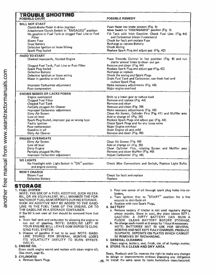
TROUBLE SHOOTINGPOSSIBLE CAUSE POSSIBLE REMEDY
WILL NOT STARTClutch-Brake Pedal in drive positionAttachment Clutch Switch in "ENGAGED" position
No gasoline in Fue! Tank or clogged Fuel Line or FuelFilter
Blown FuseDead BatteryDefective Ignition or loose WiringSpark Plug fouled
HARD TO STARTChoked improperly, flooded Engine
Clogged Fuel Tank, Fuel Line or Fuel FilterSpark Plug fouledDefective BatteryDefective Ignition or loose wiringWater in gasoline or old fuel
Improper Carburetor adjustmentPoor compression
ENGINE MISSES OR LACKS POWER
Engine overloadedClogged Fuel FilterClogged Fuel TankPartially plugged Air CleanerImproper Carburetor adjustmentDirt,/Air ScreenLow oil level
Spark Plug fouled, improper gap or wrong type
Push Pedal into brake posilion (Fig. 8)Move Switch to "'DISENGAGED" .position (Fig 9)Fill Tank with fr_;sh Gasoline. Check Fuel Line
and Carburetor (clean if necessary)Check for fault and replace FuseRecharge or replace BatteryCheck WiringReplace Spark Plug and adjust gap (Fig:. 42) .
(Fib 44)
Place Throttle Control in fast position (Fig. 9} and runstarter several times to clean out gas
Remove and clean {Fig. 44)Replace Spark Plug and adjust gap (Fig, 42}Recharge or replaceCheck the wiring and Spark PlugsDrain Fuel Tank and Carburetor, use fresh fuel and
replace Spark PlugMake necessary adjustments (Fig. 48)Major engine overhaul
Faulty ignition Check Spark Plugs and forPoor compressionGasoline in oilDirty Air Cleaner
ENGINE OVERHEATS
Dirty Air ScreenLow oil level
Dirty EnginePartially plugged Muffler
Shift to a lower gear or reduce loadRemove and replace (Fig. 44)Remove and cleanRemove and clean (Fig 39)Make necessary adjustments (Fig. 4B)Clean Air Screen, Cylinder Fins (Fig, 41) and Muffler areaAdd or change oil (Fig. 35)Replace Spark Plugs and adjust gap (Fig, 42}
any loose wiresMajor Engine overhaulDrain Engine 0il and refillRemove and clean (Fig° 39)
Clean Air Screen (Fig. 40)Add or change oil (Fig, 35)Clean Cylinder Fins, rotating Screen and Muffler areaRemove and clean Muffler (Fig. 40)
Improper Carburetor adjustment Adjust Carburetor (Fig, 48)
NO LIGHTSNo Headlight with Light Switch in "ON" position Check Wire Connections and Switch. Replace Light Bulbs
and engine running
WON'T CHARGEBlown Fuse Check for fault and replaceDefective Battery Replace
STORAGE1. FUEL SYSTEM
NOTE: THE USE OF A FUEL ADDITIVE, SUCH AS STA-BIL, OR AN EQUIVALENT, WILL MINIMIZE THE FOR-MATION OF FUEL GUM DEPOSITS DURING STORAGE.SUCH AN ADDITIVE MAY BE ADDED TO THE GASO-
LINE IN THE FUEL TANK OF THE ENGINE, OR TOTHE GASOLINE IN A STORAGE CONTAINER°If Sta-Bil is not used all fuel should be removed from fueltank.,
a. Drain fuel tank and carburetor by allowing the engine torun out of gasoline. ROTE: GASOLINE LEFT tNYOUR ENGINE WILL LEAVE GUM DEPOSITS CLOG-GING FUEL SYSTEM.
b. Dispose of gasoline if not to be used° NOTE: GASO-LINE STORED FOR SEVERAL MONTHS LOSESITS VOLATILITY (ABILITY TO BURN EFFECT-IVELY),.
2, ENGINE OILDrain (with engine warm) and replace with clean engine oil.(See chart, page 6).
3o CYLINDERS
a.. Remove Spark Plugs.
b. Pour one ounce of oil through spark plug holes into cy-linders.
c.. Turn Ignition Key to "START" position for a fewseconds to distribute oil
d. Replace with new Spark Plugs=4. BATTERY
a,. Remove battery if tractor is not used regularly duringwinter months,. Store in cool, dry place {above 50=F,)oCAUTION: A DIRTY BATTERY CAN RUIN AFLOOR CLEAN BATTERY BEFORE STORAGE°
b o Re-charge each month at 6 amps for 1 hour if necessary,.NOTE: BATTERIES NOT 1N USE FOR SEVERAL
MONTHS AND NOT KEPT FULLY CHARGED, PRODUCESULPHATE. DEPOSITS ON PLATES WHICH CANNOTBE REMOVED BY RECHARGING..
5. GENERAL CLEANING
Clean engine, battery, seat, finish, etc, of all foreign matter_6, STORE IN A CLEAN AND DRY AREA.
Sears, Roebuck and Co. reser'_es the right to make any changesin design or improvements without imposing any obligation
* 25-to install the same upon its items heretofore manufactured.
anot
her
free
man
ual f
rom
ww
w.s
ears
trac
torm
anua
ls.c
om

SCHEMATICGT 18 TWIN GARDEN TRACTOR--MODEL NUMBER 917o255915
12V .__
...........o,,,.o,,,I I
L ,, ,_..................
RED
RED
POWERTAKE-OFFSWITCH
,UTCH OFf
M
IGNITIONSWITCH
I
CLUTCH/BRAKE:O II
(PEDAL UP) ' I I= ! I
WHITE WHITE I
D E i SOLENOID
RED ELECTRIC
CLUTCHL_. RED
I I iI I
BLACK
2 TURNSCLOCKWISE ((-_)FROM FUSE
AMMETER*
BLACK
BLACK
BLACKFUSERED
30 AMP
IGNITION SWITCHSTD365402
POSITION CIRCUIT
OFF M-G
ON B_L
START B-S
G
RED
SEAT SWITCH{NOT OCCUPIED)
BLACK L
IGNITIONUNIT
SPARK PLUGS
BLACK
5 AMPS DC (POSo|22 VAC5 AMPS DCNOTE: WITH ENGII_
RUNNING @ 3600 RPM,BATTERY IN-LINELIGHTS OFF
*INDUCTIVE TYPE. WIRE COIL-ED AS SEEN FROM BACK OF
DIODEASSEMBLY
ORANGE
ENGINE COIL
(ALTERNATOR)
DASHBOARD.
LIGHTS WILL NOT REGISTER ONAMMETER_
YOUR TRACTOR IS EQUIPPED WITH ASPECIAL ALTERNATOR SYSTEM. THELIGHTS ARE NOT CONNECTED TO THEBAT-FERY, BUT HAVE THEIR OWNELECTRICAL SOURCE. BECAUSE OFTHIS, THE BRIGHTNESS OF THFLIGHTS WILL CHANGE WITH THEENGINE SPEED. AT IDLE SPEED THELIGHTS WILL DIM. AS THE ENGINE ISSPEEDED UP, THE LIGHTS WILL BE-COME THEIR BR IGHTEST.
LIGHTSWITCH
PTO SWITCH 4021J
POSITION CIRCUIT......... ,
OFF B+E, C+D
ON B+A
BROWN
BLUE HEADLIGHTS
WIRING INSULATED CLIPS
NOTE: tF WIRING INSULATED CLIPSWERE REMOVED FGR SERVICING OFUNIT, THEY SHOULD BE REPLACEDTO PROPERLY SECURE YOUR WIRING..
CHASSISGROUND
_ ...... 26 -
anot
her
free
man
ual f
rom
ww
w.s
ears
trac
torm
anua
ls.c
om

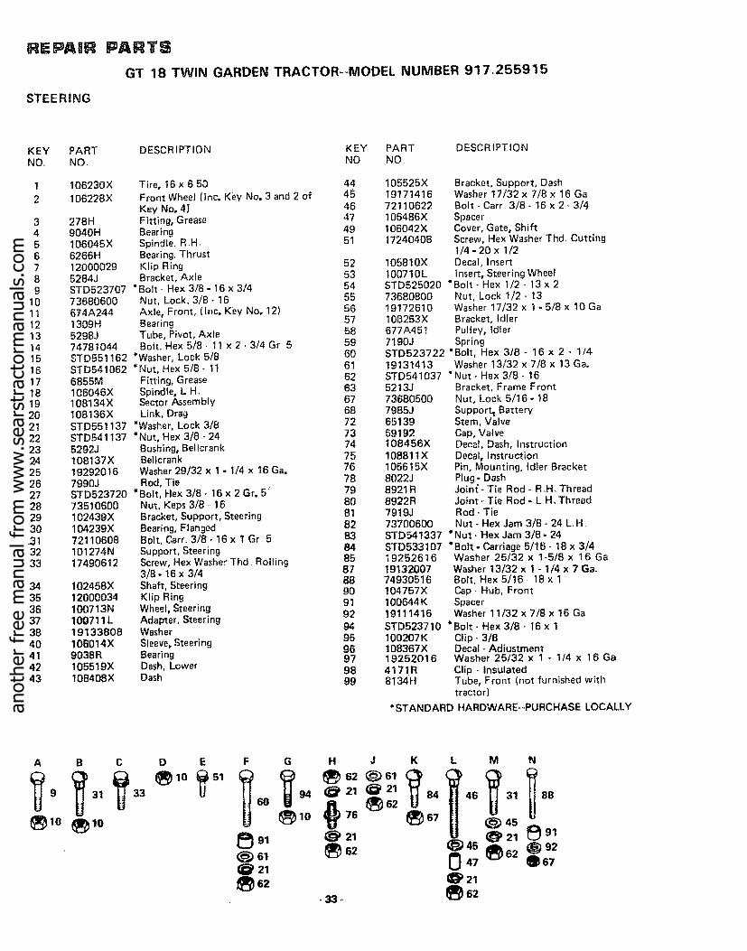
REPAIR PARTS
ELECTR ICALGT 18 TWIN GARDEN TRACTOR--MODEL NUMBER 917.255915
A
5O43
44
E
KEYNOo
t23456789
1011121314
15161718192021222324252627
48
3 2 6
PART DESCRIPTIONNO.
105613X Key SetSTD365402 Switch- tgnition! 1151000 Washer- Lock. Int. Tooth 5/83258J Nut- Hex 5/8 _32121 t11X Ammeter108240X Switch - Light9138R Batter_'7603J Tray - Battery100541K Tube - Drain109596X Clamp- Hose109081X Solenoid10090400 Washer- Lock 1/4
18
38
STD541225 *Nut- Hex -Jam 1/4 -20t7190408 Screw - Hex Washer Thread Cutting
1/4- 20 x 1/2104445X Switch - Interlock, Clutch Pedal71031008 Screw - Hex Washer No. I0- 32 x 1/273951000 Nut - Keps No. 10- 32106315X Diode Assemblyt05387X Harness - Wire
4152J Bulb- Headlight108824X Fuse- 30 Amp74610628 Bolt- Hex 3/8- 24 x 1 - 3/4ST0523707 "Bolt - Hex 3/8- 16 x 3/44207J Cable- Ground11050500 Washer- Lock - Ext_ Tooth 5116"402!J Switch * PTO4022J Nut- Hex
KEYNOo
282930313334353637383940414243444546
484950
- 27 -
A B C
t3 14 16
D E
•_ 25 49U
PART DESCRIPTIONNO,
4799J Cable - Battery7 t9J Cover - Terminal51J Cover _Terminal5115J Cable- Startert0955OX Clutch - Electric106367X Spacer- Clutch108t 70X Stop - Clutch19132203 WasherSTD551137 *Washer. Lock 3/872240460 Bolt- Carriage 1/4- 20 x 7 - 1/211030400 Washer- Lock. IntJExt,, Tooth 1/4STD541625 *Nut-Wing 1/4- 20102476X Guard. TerminalSTD522507 *Bolt- Hex 1/4 - 20 x 3/4ST055t025 *Washer 9/32 x 5/8 x 16 Ga.STD541025 * Nut- Hex 1/4 - 20ST0551125 *Washer o Lock 1/4110017X Harness - Ignition
109869X71031008109748X10t539X
120383X
Switch, SeatScrew - Hex Washer Hd. 10 - 32 x 112
Relay AssemblySheet, Instruction, Tractor t5 ° SlopeManual _ Owners
*STANDARD HARDWARE-PURCHASE LOCALLY
anot
her
free
man
ual f
rom
ww
w.s
ears
trac
torm
anua
ls.c
om

REPAIR PARTS
GT 18 TWIN GARDEN TRACTOR--MODEL NUMBER 917.255915CHASSIS AND ENCLOSURES
61
66
67
3O
33
............ 28 -
anot
her
free
man
ual f
rom
ww
w.s
ears
trac
torm
anua
ls.c
om

REPAIR PARTS
GT 18 TWIN GARDEN TRACTOR--MODEL NUMBER 917.255915CHASSIS AND ENCLOSURES
KEY PART DESCRIPTION KEY PART DESCRIPTIONNOD NO. NO. NO.
t 1t0053X2 109866X3 105529X5 736805009 110378X
10 7368060011 109593X12 106202x13 105801X14 STD52370715 105567X16 17490608
17 17490616
18 105511X19 105514X20 1055!2X21 1913201222 105531X23 105509X24 106020X25 109462X26 106082X27 6999R28 7834R29 7833R30 105465X31 I05466X32 105464X33 110892X34 110893X35 7982J36 7476071637 7368070038 108403X39 105562X40 108410X
Seat 41Pan - Seat 42Bolt - Shoulder 43Nut- Lock 5/16- !8 44Bracket - Pivot Seat 48Nut- Lock 3/8- 16 49Fender 50Refector - Tailfight 51Decal 52
* Bolt - Hex 3/8- 16 x 3/4 54Decal. Chassis 55
Screw- Hex Washer Thread Roiling 563/8- t6 x 1/2 57
Screw - Hex Washer Thread Roiling 3/8 58-t6xl 59Strap - Fender 61Clamp - Spring 62Spring- Compression 63Washer 13/32 x 1 - 1/4 x 12 Ga. 64Nut - Push 65Bracket- Fender 66Tank - Fuel 67Cap- Fuel 68Pad - Spacer 69Clamp- Hose 70Line- Fuel 7 1Line- Fuel 72Footrest - L.,H, 73Pad - Footrest 74Footrest- R H. 75Rail- Frame- RH, "* 76Rail - Frame- LH ** 77 19131312Drawbar 78 106909XBolt - Hex 7/'16- 14 x 1 79 106910XNut- Lock 7/16 - 14 80 108402XPanel - Side o R,H, 81 109867XDecal 82 275tRPanel - Side - L.H, 83 108631X
84 10964tX85 109412X
A B C D E F G H J
5 I_ 21 78(_ 77 (_ 2I _ 79
lo 37
108508X Bracket - Pivot- Frame. RHo108509X Bracket- Pivot- Frame - Loll106013X HoodI06067X Shield. Heat, Front105528X Grill108512X Bracket- Pivot- Gri]} - R,H.t08513X Bracket- Pivot - Grill - L H.I06003X Lens- R.,H,,106004X Lens- LH.106006X Bezel. L,HI06005X Bezel- RH_
I08067X Pal Nut106091X Hinge- R.H.106090X Hinge - L.,H,105524X Str.ap - Grill108743X Decat- Stripe, LH,108744X Decal - Stripe, R.H,109139X Decal - Fender106868X Decal - Drive Schematic
4900J Decal - ClutchtBrake
3645J Bushing871OJ Stem - Tank. Fuelt05806X Decal - Grill105568X Decal - Grill (Stripe)t 9131416 Washer 13/32 x 716 x t 6 Gat06092X Support, Heat Shield106088X Strip - Foam106813X Decal - Stripe. Side Panel, LH106814X Decal - Stripe, Side Panel, Roll.I06974X Decal - OPEl - Caution
STD55! 137 *Washer - Lock 3t8Washer 13)32 x t3t16 x 12Ga.Screw - SpecialWasherU-ClipSpring, CompressionClip - Fuel LineDecal IIGrommet
Spring, Cap
L M N
@70 @76,_)10 1_ 77
NOTE: When ordering Frame Rails -If your Tractor does not use a Plastic Bushing on the Foot Pedal (item 129 on page 31), thenyou must order Right Hand Frame Rail 105506X or Left Hand Frame Rail 105504>(,,
*STANDARD HARDWARE--PURCHASE LOCALLY
- 29_
anot
her
free
man
ual f
rom
ww
w.s
ears
trac
torm
anua
ls.c
om

REPAIR PARTIS
GT 18 TWIN GARDEN TRACTOR--MODEL NUMBER 917.255915
GROUND DRIVE
A B C D E F G H J
_ 10 _ "14 _13_50_22_22 _34_51 _22
16 _17 _19 32 _17
108
97 20 85
6843
73
84 \ 90
8144 54
[_- 126
c
3
/
93
41
•64
36
37'
23
29
26
3O
/31
30
123 27
17
OPTIONAL EQUIPMENT
Spark Arrester Muffler 674A380 1K L M N O P Q
(_57 _i_)_2®124 @11Q32
R S T U V W x y
95 61 111-_ 115 13 14 50
l°sE_ _ lo1_11e
_119 * (_19 _1712062 Q118@ 15
- 30 - .......
anot
her
free
man
ual f
rom
ww
w.s
ears
trac
torm
anua
ls.c
om

GT 18 TWIN GARDEN..TRACTOR--MODEL NUMBER 917o255915
GROUND DRIVE
KEY PART DESCRIPTION KEY PART DESCR 1PT'!ONNO NO, NO, NO
106637X Bracket, Support2 IO8077X Engine, 18 H,P,, Briggs and Stratton,
Model No. 422437, Type No, O749-O13 13240200 Elbow, Street4 9767H Valve, Oil Drain5 13260302 Bushing6 100229L Tube - Exhaust7 100000K Clamp - Tube8 108234X Muffler9 8545J Gasket, Muffler
10 74570412 Screw, Socket Hd.., 1/4 - 20 x 3/411 STD551 !25 "Washer, Lock, 1/412 5266J Base,Engine13 STD523707 "Bolt, Hex, 3/8- !6 x 3/414 STD523t12 *Bolt, Hex, 5i16-18x 1- l/4, Gr 5t5 STD551131 *Washer, Lock, 5/1616 STD541031 *Nu;_, Hex, 5/16 - !817 73680600 Nut, Lock, 3/8 - 1618 10t343L Pulley, Ground Drivet9 STD551137 *Washer, Lock, 3/820 19131614 Washer, 13/32 x 1 x 14 Ga21 105599X Bracket, Drive, Mule22 72110608 Bolt. Carriage 3/8- 16 x 123 106000X Bracket, V-Pulley, Drive, Mute24 19131612 Washer, 13/32 x I x 12 Ga25 101344L Pulley, Idler26 5255J Bracket, idler, Fiat27 106048X Guard, Belt, Mule Drive, Flat ldter28 106023X Guard, Belt, Mule Drive, V-Idler29 72110616 *Bolt, Carr,, 3/8- !6 x 230 STD533707 * Bolt, Carr., 3/8 - 16 x 3/431 102403X ldler, Fiat32 STD551037 *Washer, 13/32 x 13/16 x 16 Ga.33 !01347L Bracket, Flat Idler34 STD533710 "Bolt, Carr., 3/8 - 16 x 135 STD541037 "Nut, Hex, 3/8- 1636 105592X Bracket, Clutch w/Bearing (Inc, Key
No 106)37 207J Washer, Hardened38 12000039 Klip Ring39 110484X Idler, Grooved40 STD5237!5 *Bolt, Hex, 3/8- 16 x 1 - 1/24t 73930600 Nut, Lock, 3/8- 1642 101355X Spring, Extension43 STD570907 *Pin, Cotter, 3/32 x 3/444 101356L Rod, Clutch45 104360X Idler, Fiat46 STD523720 *Bolt, Hex, 3/8 - 16 x 247 1913141:3 Washer, !3/32 x 7/8 x 13Ga.48 105597X Retainer, Belt49 104577X Adapter50 STD5237t0 "Bolt, Hex, 3/8 .. 16 x 1 Gr 551 17190512 Screw, Hex, Slotted, 5/16- 18 x 3/452 105500X ,Retainer, Belt, Lower53 11)t31312 Washer, 13/32 x 13/16 x 12Ga_54 !01345M Rod, Shih, Hi-Lo55 105598X Bracket, Rod, Shift56 100196K _ Knob57 73680500 Nut, Lock, 5/16- 1858 STD571810 *Pin, Cotter, 3/t6 x !59 10!342_1 V-Belt60 120404X Bracket, Support, TransaXte61 74760716 Bolt, Hex, 7/16- 14 x 162 STD551143 "Washer, Lock 7/1663 101341M Pulley, Transaxle64 9204H Nut, Lock, 1/2- 20
65 104375X66 1925201667 STD57181268 I06021X69 5693J70 177204087t 104596X72 1105060073 STD54113774 8883R75 677A63776 74370612
1291_3(}
-3; •
747606147920J72140405
Shaft, Foot PedalWasher, 25/32 x 1 - t/4 x 16 GaPin, Roll, 3/16 x 1 - 1/4Spring, ExtensionControl, ThrottleScrew, Hex, Thd, Cut, 1/4 - 20 x t/2Control, ChokeWasher, Lock, Ext Tooth, 3/8
*Nut, 3/8 - 24Cover, PedalBracket, BrakeScrew, Mach., Unct FL Hd., 3/8 -16x 3/4Bolt, Hex, 3/8- 16 x 7/8Band, BrakeBolt, Carr,.0 1/4 - 20 x 5/8
77787980 STD5,41025 "Nut, Hex, 1/4 - 2081 7229J Guide, Rod, Brake82 1685H Nut, Lock, 5/16, 1883 STD533107 "Bolt. Cart, 5/16- 18x 3/484 5308J Rod, Brake85 7241J Spring, Compression86 73530600 Nut, Lock, 3/8- 2487 100604 K Yoke88 5102J Pin, Clevis89 71673 Cap, Plunger90 109767X Rod, Parking Brake91 19111216 Washer, 11/32)= 3/4 x 16 G_,.92 634A692 Bushing and Wheel Hub93 7563R Washer, Thrust, Axle94 12000034 Klip Ring95 !304H Bolt, Hub96 t06277X Wheel, Rear97 105588X Tire, Rear98 65139 Valve, Tire99 59192 Cap, Valve
t00 214J Drum, Brake101 STD541410 *Nut- Lock No 10,, 24t02 633A109 Gear Shift Lever Assembly103 2228M Key, Woodrufft05 74760724 Bolt, Hex 7/16- 14 x 1 - 1/2106 101350K Bearing- idler108 61159 Knob. Throttle Control109 9858M 1 Key - Woodruff110 5304J Actuator ° Switch, Interlock11 t 74321016 Screw- Fin 10,24 x 11!2 13280252 Nipple, Pipe!13 19132012 Wash{r 13/32 x 1 - 1/4 x t2 Ga.114 104601X Bracket ,.Interlock115 STD522507 "Bolt- Hex 1/4 ,,20 x 3/4116 73680400 Nut - Crowntock 1/4 - 20118 19131210 Washer 13/32 x 3/4 x 10 Ga_119 73680700 Nut ,.Crowntock 7/16 - t4120 11050500 Washer - Lock Ext. Tooth 5/16!21 76020816 Pin ..Cotter 1/4 x 1122 10t358K Bracket - Assembly Clutch123 19131612 Washer t3/32 x 1 x 12 Ga,124 STD551025 *Washer 9/32 x 5/8x 16Ga.,125 72140506 Bolt- Carriage 5/t6- 18 x _J'/4t26 1 t0042X Decal, 18 H,P., Craftsman127 13300300 Coupling, Pipe, Std, 3t8 - 1B NPT128 105474X Transaxle Assembly (less Brake Drum
end Shift Lever)11089"5X_ Bushing, Flanged7154J Tube, "Tire (not furnished with tractor}
"STANDARD HARDWARE--PURCHASE LOCAI_LY
anot
her
free
man
ual f
rom
ww
w.s
ears
trac
torm
anua
ls.c
om

REPAIR PARTS
GT 18 TWIN GARDEN TRACTOR--MODEL NUMBER 917.255915
STEERING
,37
-4oM, 75
L
LG
78 D
\
29
22
54
34
2018
B
2221
26
15
28
22
27
3
4
2
82
72
81
83
97
7- 32 -
anot
her
free
man
ual f
rom
ww
w.s
ears
trac
torm
anua
ls.c
om
RE PA IR
STEERING
PARTS
GT 18 TWIN GARDEN TRACTOR-+MODEL NUMBER 917.255915
KEY PARTNO, NO,
12
3456789
1011121314t51617t8192O2!22232425262728293O313233
34353637384O414243
DESCRIPTION KEY PART DESCRIPTfONNO NO
106230X
106228X
278H9040H106045 X6266H120000295284J
Tire, 16 x 650 44 105525XFront Wheel (inc. K_y No. 3 and 2 of 45 19171416Key No. 4i 46 72110622Fitting, Grease 47 106486XBearing 49 ! 06042XSpindle. R +H_ 51 17240408Bearing. ThrustKlip Ring 52 1058t0XBracket, A×le 53 I00710L
STD523707 "Bolt +,Hex 3/8 - 16 x 3/4 54Nut. Lock. 3/8- 16 55 73680800
Axle, Front, (Inc. Key No. 12) 56 19172610Bearing 57 108253XTube, Pivot, Axle 58 677A45!Bolt. Hex 5/8 - 11 x 2 - 3/4 Gr 5 59 7190J
"Washer, Lock 5/8 60 STD523722"Nut. Hex 5/6 + 1t 6t 19131413
Fitting, Grease 62 STD541037 "Spindle. L+H, 63 5213.ISector Assembly 67 73680500Link. Drag 68 7985J
*Washer, Lock 3/8 72 65139STD541137 *Nut, Hex 3/8 +24 73 591925292J Bushing, Beltcrank 74 t08456X108137X Betlcrank 75 10681tX19292016 Washer 29/32 x 1 - t/4 x !6 Ga, 76 106615X7990J Rod, Tie 78 8022JSTD523720 *Bolt, Hex 3/8- 16x 2Gro5" 79 8921R73510600 Nut, Keps 3/8 + 16 80 6922R102439X Bracket, Support, Steering 81 7919J104239X Bearing, Flanged 82 7370060072110608 Bolt, Cam 3/8 - 16 x 1 Gr 5 83101274N Support, Steering 8417490612 Screw, Hex Washer Thd Rolling 85
873f8 - 16 x 3/4 88
102458X Shaft, Steering 9012000034 Klip Ring 91100713N Wheel, Steering 92100711L Adapter, Steering 9419133808 Washer 95106014X Sleeve. Steering 969038R Bearing 97!05519X Dash, Lower 9810B408X Dash 99
73680600674A2441309H5298J74781044STD551162STD5410626855M106046X108134Xt08136XSTD551137
Bracket, Support, DashWasher t7/32 x 7/8 x 16 GaBolt+Carr 3/8616x2-3/4
SpacerCover, Gate, ShiftScrew, Hex Washer Thd, Cutting1/4- 20 x 1/2Decat, Insertlnsert. Steering Wheel
STD525020 "Bolt + Hex 1/2 .. 13 x 2Nut, Lock 1/2- t3Washer 17/32 x I - 5/8 x 10 GaBracket, IdlerPulley, idlerSpring
"Bolt, Hex 318 - 16 x 2 - 1!4Washer 13/32 x 7/8 x 13 Ga,Nut- Hex 3/8 ,-16Bracket, Frame FrontNut, Lock 5/t6- 18Su pport_ BatteryStem, ValveCap, ValveDecal Dash, InstructionDecal, InstructionPin. Mounting. Idler BracketPlug o DashJoint +Tie Rod - R,.H. ThreadJoint- Tie Rod - L,H "ThreadRod - TieNut. Hex Jam 3/8 - 24 L,H
STD54t337 *Nut .+Hex Jam 3/8- 24STD533107 "Bolt - Carriage 5/16- t8 x 3/419252616 Washer 25132 x 16518 x 16 Ga19132007 Washer t3/32 x 1 + 1/4 x 7 Ga+74930516 Bolt. Hex 5/16 + 18 x 1!04757X Cap., Hub, Front100644 K Spacer19111416 Washer 11/32 x 7/8 x 16 Ga
STD523710 *Bolt- Hex 3/8 - 16 x 1I00207K Clip +3/8108367X Decal- Adiustment19252016 Washer 25132 x 1 - 114 x 16 Ga417!R Clip + Insulated8134H Tube, Front (not furnished with
tractor)
*STANDARD HARDWARE--PURCHASE LOCALLY
A B C D E F G H J K L M N
9, o 2,_ 2, l_) 62 84 46 31 8B9 31 33 60 (_ 10 76 67
_) 10 10 45 _ 91
m 62 4s 62 9247 _67
j_62 @ 21• 33+ _62
anot
her
free
man
ual f
rom
ww
w.s
ears
trac
torm
anua
ls.c
om

......... ,,,,,,,,, ,,,,HHH, I IIII IIIIIII IIIIIIIIIII................ ,,,, ,,=,,=H,, _,H N IIIIIIII illlllJlL Jill .........
REPAIR PARTS
MOWER LIFT
,b,i
1
6
41
3
42
58
r6O
GT 18 TWIN GARDEN TRACTOR--MODEL NUMBER 917.2559155O
46
49
26
4140
16
TFo° F
44
anot
her
free
man
ual f
rom
ww
w.s
ears
trac
torm
anua
ls.c
om

or&LO
reW
Z
W00
0p.
ZW
CC
Zmm
k-
I-
Z0
b_
0
tl!o
t-
_dN:Z
Z
o
Q=
0U_tll0
x _ T _: '_oP._'_ox
o _,. "7"_- _ _ _'a _c3 5 _ .,_ _
,--,-- U_ ,-- r_ Cb,- U} O0 ,-*_ r--(0 ,--K+O ,e-,-- '-" ,--
_D
.= _ o
e- w'.
_ _._: .
x x _tm ._m m
t'_ p,.
_t-O "LO ,"- 0o, ooNo_om
0
I
r_
5
x
CO0
0
40
X
× ,-
x
c'4
,__ o_-__ o _- , _ ._'r o_ o _,__,.c _X._
$ * 4, $
0 0 o 0 o _0 0 o
>-J-J
<00.J
_U
0O:Dr_
U_rr
<
_E
0rr
o
.f.f_>
X XX
IN' €_
l wO
- 35 -
anot
her
free
man
ual f
rom
ww
w.s
ears
trac
torm
anua
ls.c
om

REPAIR PARTS
GT 18 TWIN GARDEN TRACTOR--MODEL NUMBER 917.255915MOWER
51
34
15
17
G
16
C
60
1618
17
51
26
71
5857 51
35
46
35 35
36
32
38
73
55
47
47
44 55
49
- 36_
anot
her
free
man
ual f
rom
ww
w.s
ears
trac
torm
anua
ls.c
om

RE IR
MOWER
PARTSGT 18 TWIN GARDEN TRACTOR--MODEL NUMBER 917,255915
KEYNO_
123
456789
101t12t314
1516171819202122232425262128293031323334
PARTNO,,
DESCRIPTION KEY PART DESCRIPTIONNO, NO
105415X106022X17490508
7631J72110505STD551131ST054103!8418J72140506_6B5HSTD551031105483Xt06038X17490612
106635X
Housing, Mower 35 73680600Cover- Drive, Deck 36 105453XScrew - Hex Washer Thd= Rb!l 5/16- 37 5565J18 x I/2 38 4939MRunner, LH,, 39 4898HBolt, Cart, 5/16- 18 x 5/8 40 t05455X
*Washer-Lock, 5/16 41 105433X*Nut-Hex 5/16- 18 42 110237X
Runner, R,H 43 105434XBolt, Carr. 5/16- 18 x 3/4 44 I05436X
' Nut, Lock 5/16- 18 45 105441X*Washer t t/32 x t 1/16 x 16 Gao 46 78850
Mandrel - Secondary 47 3146RMandr_l - Primary 48 106381XScrew - Hex Washer Thd, Roll 3/8- 4916 x 3/4 50 74760622Blade 51 105435X
ST0623715 * Bolt - Hex, 3/8 = 24 x 1 - I/2 Gro 5 52 3720RSTD551137 *Washer-Lock, 3/8 53 1200003919132012 Washer 13/32 x 1 - 1/4 x 12 Ga. 54 19171612
674A213 Arm Assembly, Idler 55 105440X7834J Liner, Bearing 56 105456X7835J Bearing 57 105460X72110522 Bolt, Carriage 5/16- 18x 2-3/4 58 t05461X19111610 Washer !1/32 x 1 x 10 Ga, " 59 105457XI02403X Pulley, Idler 60 73680500STD523715 *Bolt- Hex 3/8- 16x I - 1/2 62 19111016STD541037 *Nut- Hex 3/8- 16 63 109785X104361X Spring 64 106734XST0523112 *Bolt- Hex 5/16- 18 x 1 - 1/4 Gr, 5 65 109743X!9111216 Washer t 1/32 x 3/4 x 16 Ga_, 66 I06735X
8438J Spacer 68 110452X106224X Decal- V-Belt. Dr., Schematic, Mower 69 3713J105448X Bracket, Ga Wheel, R,H, 71 73680800!05449X Bracket, Ga, Wheel, LH 73 19171512STD533707 *Bolt, Carriage 3/8 - 16 x 3/4 74 72240608
75 106679X76 106863X77 106975X
Nut, Crownlock 3/8 - 16Bar, Ga, WheelPin, ClevisRetainer, SpringBolt, ShoulderWheel, GaugeBrkt., SuspensionSpacerBrace, SuspensionParallel LinkBrkt,, SuspensionDecal - WarningRetainer - SpringV-Belt
ST054!050 *Nut, 1/2- t3Bolt, Hex 3/8- 16 x 1 - 3/8Pin, ReleaseSpringRing, KlipWasher 17/32 x 1 x 12 Ga,Pin, ClevisBrkt,, Outer, R ,H,
,Brkt,, Inner, R.H.Brkt., Inner, L.H.Brkt., Outer, LH,Loeknut 5/16 * 18
Washer 11/32 x 5/8 x 16 Ga.Shield, DeflectorSpring, DeflectorBracket, DeflectorRod. HinaePush NutInstruction - Caution DecalNut- Lock 1/2- 13Washer 17/32 x 15/16 x 12 Ga
Bolt, Carriage 3/8 - !6 x I tDecal - WarningV-BeltDecal
*STANDARD HARDWARE--PURCHASE LOCALLY
A B C D E F G H
35
anot
her
free
man
ual f
rom
ww
w.s
ears
trac
torm
anua
ls.c
om

REPAIR PARTS
TRANSAXLEGT 18 TWIN GARDEN TRACTOR--MODEL NUMBER 917.255915
3
45
46
l2
e
15
14
7O74
89
70
73 68_
49
9293
IIII1!111IIII I II I
- 38 -
/,4,_-f98
7
13
37
i1_--40
2524
anot
her
free
man
ual f
rom
ww
w.s
ears
trac
torm
anua
ls.c
om

REPAnR PARTS
GT 18 TWIN GARDEN TRACTOR--MODEL NUMBER 917.255915
TRANSAXLE
KEY PART DESCRIPTION KEY PART DESCRIPTIONNO. NO, NO NO
12345678
91011121314151617181920212223242526272829303!
3233343536373839
40454647
48
4197R Axle Shaft 49 4895H5845R Retaining Ring 50 4222R4199R Final Drive Gear 51 1529R4216R Differential Gear 52 8119M4215R Differential Pinion 53 4220R4217R Differentia! Carrier 54 4209R6256H Axle Thrust Washer 55 4213R74020652 Hex Bolt 3/8., 24 x 3 - 1/4 56 4442R
(1" Thread Length) 57 4195R7392M Steel Ball 58 4214R6272H Spring Shift Fork Detent 59 4194R4985R Shift Fork, High ,, Low Range 60 7528R626614 Thrust Bearing Race 61 4208R4212R 4th Reduction Pinion 62 4207R4196R 3rd Reduction Gear Shaft 63 7398146276H Snap Ring .. Crescent Type 64 4203R633A63 High ,, Low Range Gears81 !8M Needle Bearing 65. 4204R8740Ht Sintered Iron Bearing 66 2898J6217H Shift Fork Shaft, High., Low Range 67 4926H4218R Differential Pinion Spacer 68 4205R6252H1 Differential Pinion Bushing 69 4206R78t0H Gripco Centerlock Nut 3/8., 24 70 1370H4986R Shift Fork-. LH 71 633A697393R Oil Seal992R1 Sintered Iron Bearing 72 208J6216H Shift Fork Shaft 73 4201R6262H Shift Fork-, R,H, 74 12000002101416X Shift Shaft, High- Low Range 75 1153R6269H Oil Seat 76 7392H5855H Pressure Relief Valve 77 3990H!05406X Gearcase, Reverse Idler Shaft and 78 STD541031
Bearings *,R.H (Inc. Key No_s. t7, 79 1167R18, 25, 33, 50, 63° 76, 77 and 82) BO 73360700
627714 Dowel Pin 81 6270H4225R Needle Bearing 82 7384H7396H Thrust Bearing Race 83 t00196K4198R 4th Reduction Gear Shaft 84 5384J4200R 4th Reduction Gear Spacer 85 2976J7395H Thrust Bearing Race 86 633A856275H Gearcase Gasket 87 6739H1t05402X Gearcase and Bearings - L.H, 88 4924H
(Inc Key No_s 18, 25, 49, 50 (2), 89 1915151651 and 52) 90 8105R
13060400 Pipe Plug 1/2-, 14 N P.T., 91 191815116271H Oil Seal 92 75J13020200 Pipe Plug 1/4 ,, 18 N ,P,T 93 6274H
STD523115 "Hex Bolt 5/t6 _ 18 x 1 - I/2 94 76020412Grade 5 95
10140500 Lockwasher 5/16 Extra Heavy 969798
Needle BearingNeedle BearingNeedle BearingNeedle BearingThrust Bearing Race3rd Reduction Pinion ,, Low4th Reduction Gear3rd Reduction Pinion Spacer2nd Reduction Gear ShaftFinal Drive Pinion1st Reduction Gear Shaft1st Reduction Shaft Spacer3rd Reduction Pinion ,. High2nd Reduction GearNeedle BearingLow Speed Gear and 2nd ReductionPinion CIusterReverse GearKey - Hi., Pro 1/8 x 17/32
Snap Ring ,, Grescent TypeIntermediate Speed GearHigh Speed GearThrust Bearing Raceintermediate and High Speed ClusterPinionsInput ShaftLow Speed PinionE-RingReverse tdier GearReverse Idler Thrust WasherNeedle Bearing
"Hex Nut 5/16-- 18Sealing WasherHex Jam Nut 7/16 -,20Oil SealReverse Idler ShaftControl KnobGear Shift Lever - BentGear Shift CapGear Shift Ball Cover and PinShift Lever Guide Ball ,-KeyedSpringWasher 15/32 x 15/16 x 16 Ga,Shift Mechanism SealWasher 9/16 x 15/16 x 12 Ga,Gear Shift Gate and ReinforcementShift Ball Cover GasketCotter 1/8 x 3/4
STD551131 "Lockwasher 5/16STD52310B °Hex Bolt 5/16 ._18 UNC x 7/8633At09 Gear Shift Lever Ass=y,
105474X Transaxle Assembly Less Brake Drum& Shift Lever
*STANDARD HARDWARE--PURCHASE LOCALLY
anot
her
free
man
ual f
rom
ww
w.s
ears
trac
torm
anua
ls.c
om

REPAIR PARTSGT 18 TWIN GARDEN TRACTOR--MODEL NUMBER 917,255915ENGINE--MODEL NUMBER 422437, TYPE NUMBER 0758-01
CYLINDER, CRANKSHAFT AND ENGINE BASE GROUP
- 40 -
anot
her
free
man
ual f
rom
ww
w.s
ears
trac
torm
anua
ls.c
om

REPAIR PARTSGT 18 TWIN GARDEN TRACTOR--MODEL NUMBER 917.255915ENGINE--MODEL NUMBER 422437, TYPE NUMBER 0758-01
CYLINDER, CRANKSHAFT AND ENGINE BASE GROUP
KEY PART DESCRIPTION KEY PART DESCRIPTIONN 0 NO. NO. NOn
0 1 491685 Cylinder Assembly0 2 391086 Seal-Oil03 212461 Head-Cylinder No, I04 212462 Head-Cylinder No_ 205 271867 Gasket-Cylinder Head No t06 271868 Gasket-Cylinder Head No 20 7 393243 Breather Assembly No,, I0 8 393153 Breather Assembly No,, 20 9 27803 Gasket-Valve Coveri 0 93394 Screw_SemI I 270982 Gasket_Crankcase Cover
1/64" Thick1 1 271145 Gasket-Crankcase Cover
,005"" Thick1 I 271146 Gasket-Crankcase Cover
.,009"" Thick1 2 93113 Screw-Cylinder Head
(2_5/16" long)1 3 93111 Screw-Cylinder Head
(I- 15/16" long)1 4 Plyg-Oi! Drain15 394430
1 6 394535i 7 2916751 8 938471 9 394955
19 39495619 39495719 394958
20 39495920 3949602 0 39496120 3949622 1 398990
22 26092423 299691
23 39128624 394306
25 22305326 929092 7 39042028 6590629 2682830 2215963 1 29226032 9363033 261368
Crankshaft - order part 94196Key for retaining timing gearCover Assembly - CrankcaseSeal-Oil
Screw-Crankcase cover Mtg, SerePiston Assembly-Standard lnc, KeyNo,'s 20 & 22)Piston Assembly - •010"" O S..Piston Assembly - ,.020"" O S.,Piston Assembly - ,030" O,S,Ring Set - Piston - StandardRinge Set-Piston - _010"" O ,S.Ring Set - Piston - 020" O.S,Ring Set - Piston -, 030" O.So)Dipstick and Tube Assembly (inc,Key No's. 44, 45 & 46)Lock-Piston PinPin Assembly - PistonStandard (Inc, Key No., 22)Pin - Assembly-Piston- O05"" OoS,Rod Assembly-ConnectingFor Connecting Rod with ,020""Crankpin bore order No. 397158Dipper-Connecting RodScrew-Connecting RodValve-Exhaust
SpringJntake ValveSpring-Exhaust ValveRetainer-intake ValveRotocoil-ExhaustRetainer=Exhaust Valve RotocoflTappet-Valve
3 4 212337 Gear-Cam35 271316 Foam Seal - Governor Shaft3 6 296004 Pipe - Fuel 23" cut to lenght3 7 394348 Gear - Governor.3 8 89838 Wrench-Spark Plug3 9 220863 Washer-Gov., Crank (inside)40 394539 Plug-Spark (Resistor))2_3/8
high.6Omm)4 I 90576 Nut-Hex 8-324 2 231774 Terminal4 3 280180 Gommet - Insulator4 4 398924 Cap and Dipstick-Oill Filler4 5 68838 Seal-Filter Tube4 6 280220 Tube - Oil Filler4 7 93783 Screw-Hex Hd4 8 223055 Trough-Dipper4 9 394391 Base-Engine5 0 270981 Gasket-Engine Base5 ! 222700 Guide Air5 2 93053 Clamp*Fuel Pipe5 3 93851 Retianer-E-Ring5 4 394396 Crank-Governor5 5 66538 Etbo w-Spark Plug5 6 93448 Plug.Hex Socket5 7 222698 Key-Flywheel5 B 220863 Washer59 222773 Washer-Thrust
60 231445 Gear-Timing6 1 393606 Seal Ass'y, and Retainer6 2 39374 t Bearing-Ball (P,,T, 0 side)6 3 26196 t Guide-Exhaust Valve
NOTE: 231218 Intake Valve Guide
Only (Brass)6 4 210940 Seat-Exhaust Valve (Standard)6 5 261463 Seat-Intake Valve (Standard)66 261559 Lower Bushing _ Gov6 7 398808 Wire-Ground
68 230318 COnnector-Fuel Pipe6 9 92 791 Washer-Lock Shakeproof70 93722 Terminal-Spade7 1 261528 Valve,Intake7 2 92268 Washer
73 191523 Bearing-CylinJer74 261560 Upper Bushing-Governor7 5 93886 Screw7 6 271170 Seal Tube7 7 271174 Gasket - Exhaust
*INCLUDED IN GASKET SET 394501+ SPECIAL TOOLS REQUIRED TO INSTALL
anot
her
free
man
ual f
rom
ww
w.s
ears
trac
torm
anua
ls.c
om

REPAIR PARTSGT 18 TWIN GARDEN TRACTOR-MODEL NUMBER 917.255915ENGINE--MODEL NUMBER 422437, TYPE NUMBER 0758-01
AIR CLEANER-CARBURETOR GROUP
_9
6 8
71 Carburetor Overhaul Kit I /
44 /
73
- 42 -
anot
her
free
man
ual f
rom
ww
w.s
ears
trac
torm
anua
ls.c
om

REPAaR PARTS
GT 18 TWIN GARDEN TRACTOR--MODEL NUMBER 917.255915ENGINE--MODEL NUMBER 422437, TYPE NUMBER 0758-01
AIR CLEANER_-CARBURETOR GROUP
KEY PART DESCRIPTION KEY PART DESCRIPTIONNO. NO. NO • NO,
1 2801852 2801983 2129994 2714125 2708846 934157 932088 491630
91541
1 0 23031811 23120912 491538t3 93499
!4 22193915 3926721 6 919201 7 261571B 27160719 298514
20 2308962 I 39468122 491665
23 22353424 3926732 5 941522 7 9389728 23133829 22275230 212706
Tube*Breather 3 1Tube-In take 3 2Manifold Ass'y intake 33+ *Gasket.Carb Mtg 34
Gasket-Intake Manifold Mtg 3 5Screw Curb MTG Sem 36Screw Intake Manifold Mtg Sere 3 7Carburetor Assy (Inc Key No*s 389. 10, 1!, 12, 13: 14. 15, t6. I7. 3918. 19. 20. 2t 22, 23, 24. 25
28. 44, 46, 47, 48 49. 50 51. 40 222,2895t, 63. 64 & 65 4 t 93163Body Assembly o Upper Carburetor 4 2 221535fine Key No's I0 13 t8 23 & 4,3 8389324) 4 4 397882Connector _ Fuel 4 5 231172Bushing-Throttle Shaft 52 271271+ Valve Ass'y -Carb Idle 53 2714 11
Screw*Throttle and Choke Valve 5 4 271180Mtg Sem 5 5 93853Valve- Throttle 5 6 92278Shaft and Lever-Throttle 5 7 223001Screw-Much Fil Hd 8.32 x 5/8 5 8 222835
Spring - Throttle Adj, ' 5 9 93496+ "Gasket_Carburetor Body 6 0 392643
Float-Carburetor Body÷ Pin-Float Hinge 6 1+ Valve-Fuel Inlet 6 2Body • Lower Carburetor (lnc Key 63No°s, 11, 13, 14, 15& 65) 66Valve-Choke 6 7Shaft and Lever-Choke 6 8Screw-Hex Head Sere t0/32 x 3;4 69Screw-Casing ClampJet-Needle Valve 7 0Body.Air Cleaner 7 1Knob-Air Cleaner 72
73
93715 Nut-Hex261444 Kink.Governor261531 Link Speed Control26 ! 720 Spring-Governor25 I563 Spring - Governor Idle222807 Bracket-Speed Control222828 Lever.Speect Control394324 Plate Ass'y Governor Control393846 Lever Ass*y Governor tlnc Key
No's 40 55 & 56)WasherSo're w., Sere
Clamp- CasingSere w,SemPlug flnc Key No 28A)Bushing.Speed ControlElement.Air Cleaner
Gasket ,Air CleanerWasherBolt-Governor LeverNut-HeCover.Air CleanerCartridge Plate.Air CleanerScrew_Sem
Mounting Strap Ass'y Air Cleaner(Inc Key No 43)
66432 Washer Plain394018 Cartridge-Air Cleaner27 I013 ÷ Washer-Choke Shaft93828 Screw-Sem394358 Fitter-Fue!93053 Clamp-Fuel Pipe393815 Fuel_Line 128"1 (cut to required
length tl- I_41394501 Gasket Set491539 Carburetor Overhaul Kit
2234 72 Plug . Welch2804 74 O-Ring Seal
"INCLUDED IN GASKET SET+INCLUDED IN CARBURETOR OVERHAUL K_T°HIGH ALTITUDE - JET NEEDLE
VALVE - PART NO 231333
o4:3 -
anot
her
free
man
ual f
rom
ww
w.s
ears
trac
torm
anua
ls.c
om

REPAIR PARTS
GT 18 TWIN GARDEN TRACTOR--MODEL NUMBER 917.255915ENGINE--MODEL NUMBER 422437, TYPE NUMBER 0758-01
STARTER MOTOR GROUP
23
24
t14
25
33 _ 2021
22
1
3_4_5 12/
11
6 10
15
7
18
k-J
17
KEYNO_
3456789
10
11121314
151617
PARTNO.
394891
394970
221798933813949883929569.36219334339259539 I362
2290621241839382519203
94003395538
395537
DESCRIPTION
Armature Group tlnc Key No's2,3&5)Capsule Assembly _ Magnetron ®IgnitionTerminal - Ignition CableScrew - Armature Mtg. SereArmature Ass'y.Flywheel and Ring Gear Ass'y.Screw - SereScrew*RegulatorStarer - Alternator
Gear - Flywheel Ring (IncludesMounting Parts)Nut Flywheel LockFan - BoosterHousing Assembly
Puller - Flywheel {OptionalAccessory)Thru BoltBrush Set
Commutator End Cap Ass'yStarter (Inc. Key No. 16)
KEYNO.
!8
1.92021222324
25
2627282930313233
PARTNO.
394808
3908373948603911352801049036691162
393254
937549267422.300823124739353793808271174396865
393422
DESCRIPTION
Motor _ Starting (inc, Key No's.13, 15, 16, 17, 19, 20, 21, 22,23 & 24)
Amature Assembly (Motor)Drive End Cap Ass'y. - StarterClutch Ass'yGear'Lock washerScrew . Hex Hd - 5/16- 18x I -1t2"'
Kit - Pinion Spring {Inc Key No's.22 & 26)Roll PinScrew - Hex Hd.
Screen - RotatingNut - JamConnector - Tri CircuitScrew-SereGasket - Exhaust
Starter Drive Group (Inc_ Key No's.21, 22, 25 & 26)Alternator Harness Assembly
anot
her
free
man
ual f
rom
ww
w.s
ears
trac
torm
anua
ls.c
om

REPAmR PARTSGT 18 TWIN GARDEN TRACTOR--MODEL NUMBER 917,255915ENGINE--MODEL NUMBER 422437, TYPE NUMBER 0758-01
MUFFLER, AIR GUIDE AND HOUSING GROUP
/1
)2
4
f
3J2
5
KEYNO,
12345
6789
10
PART DESCRIPTIONNO,
396088 Heusing_Blower93158 Screw - Sem93777 Screw - He_ H392934 Back Plate Assembly222848 Cover - Air Guide
222846 Shield . Cylinder93163 Screw - Sere222847 Shield - Cylinder222849 Cover - Air Guide491262 Decal Kit
- 45 - k_k
anot
her
free
man
ual f
rom
ww
w.s
ears
trac
torm
anua
ls.c
om

SERVICE NOTES
• -46 -
anot
her
free
man
ual f
rom
ww
w.s
ears
trac
torm
anua
ls.c
om

SUGGESTED GUIDE FOR SIGHTING SLOPES FOR SAFE OPERAT|ON
ONLY RiDE UP AND DOWN HILL
NOT ACROSS HiLL
SIGHT AND HOLD THIS LEVEL WITH
SKY LiNE OR TREE
Operate your Tractor up and down the face of slopes (notgreater than 15°); never across the face. Make turns gradu-ally to prevent t=ppmg or loss of controi. Exercise extremecaution when changing direction on slopes.
anot
her
free
man
ual f
rom
ww
w.s
ears
trac
torm
anua
ls.c
om

OWNERSMANUAL
MODEL NO.917.255915
HOW TO ORDERREPAIR PARTS
G 18 TWIN6 SPEED
GARDEN TRACTOR
The Model Number wilt be found on the Model Plate attached to
the Fender. Always provide the Model Number when requestingservice or repair parts for your Garden Tractor°
All parts listed herein may be ordered from any Sears ServiceCenter/Departments and most Sears Retail Stores_
WHEN ORDERING REPAIR PARTS, ALWAYS GIVE THE FOLLOW-ING INFORMATION:
O THE PART NUMBERIt THE PART DESCRIPTIONil! THE MODEL NUMBER• THE NAME OF MERCHANDISE
Your Sears merchandise has added value when you consider Searshas service units nationwide staffed with Sears trained technicianshaving the parts, tools and the equipment to,insure that we meetour pledge to you, "We Service What We Sell",
Sears, Roebuck and Co. Chicago, IL 60684 U.S.A.120383X. 11 ._16.87 Ray. 2Printed in U.S.A.
anot
her
free
man
ual f
rom
ww
w.s
ears
trac
torm
anua
ls.c
om


![Ý > ) > § > Á > ä > > » > ) > Â > > ¬ > æ > ¥ > C > Â > ´ > · PDF fileI µ\µ\ó ò « ó Â Ø i\Ø X N : Ë\¿\ý\ ° ¬ ¯\Ø Í\¶ ù ö]c ® â\Á\Ð\®\õ ® Ã\Ø](https://img.pdfslide.net/doc/110x75/5aafe7837f8b9a59478de92f/-c-i-x-n-c-0-u-drmdh-.jpg)


![MPIA 15 459 1133 - · Dst: Type: icmp time exceeded in-transit [tos OxcO] /-----, -----\ > > > > > > > > > ® . MPIA 15 459 11302/17/99 , !](https://img.pdfslide.net/doc/110x75/5ab91efd7f8b9ac10d8dd314/mpia-15-459-1133-type-icmp-time-exceeded-in-transit-tos-oxco-.jpg)