Embed Size (px)
Citation preview

190-01499-02 June 2017 Revision 9
GTX 3X5 TransponderTSO Installation Manual

Record of Revisions
© 2015-2017 Garmin International, Inc. or its subsidiariesAll Rights Reserved
Except as expressly provided herein, no part of this manual may be reproduced, copied, transmitted, disseminated, downloaded or stored in any storage medium, for any purpose without the express prior written consent of Garmin. Garmin hereby grants permission to download a single copy of this manual and of any revision to this manual onto a hard drive or other electronic storage medium to be viewed and to print one copy of this manual or of any revision hereto, provided that such electronic or printed copy of this manual or revision must contain the complete text of this copyright notice and provided further that any unauthorized commercial distribution of this manual or any revision hereto is strictly prohibited.
©2017 Bluetooth® word mark and logos are registered trademarks owned by Bluetooth SIG, Inc. and any use of such marks by Garmin is under license. Other trademarks and trade names are those of their respective owners.
Garmin® is a registered trademark of Garmin International or its subsidiaries.
All other product or company names that may be mentioned in this publication are trade names, trademarks, or registered trademarks of their respective owners.
At Garmin, we value your opinion. For comments about this guide, please e-mail [email protected].
For comments about Garmin aviation products, email [email protected].
For information about the Aviation Limited Warranty refer to Garmin’s website.
For aviation product support, refer to flyGarmin.com.
190-01499-02 GTX 3X5 Transponder TSO Installation ManualRev. 9 Page i
Record of Revisions
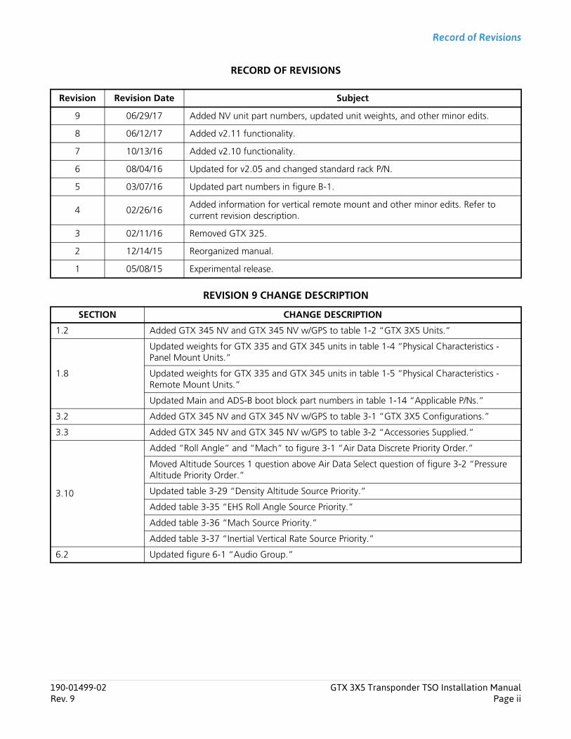
RECORD OF REVISIONS
REVISION 9 CHANGE DESCRIPTION
Revision Revision Date Subject
9 06/29/17 Added NV unit part numbers, updated unit weights, and other minor edits.
8 06/12/17 Added v2.11 functionality.
7 10/13/16 Added v2.10 functionality.
6 08/04/16 Updated for v2.05 and changed standard rack P/N.
5 03/07/16 Updated part numbers in figure B-1.
4 02/26/16Added information for vertical remote mount and other minor edits. Refer to current revision description.
3 02/11/16 Removed GTX 325.
2 12/14/15 Reorganized manual.
1 05/08/15 Experimental release.
SECTION CHANGE DESCRIPTION
1.2 Added GTX 345 NV and GTX 345 NV w/GPS to table 1-2 “GTX 3X5 Units.”
1.8
Updated weights for GTX 335 and GTX 345 units in table 1-4 “Physical Characteristics - Panel Mount Units.”
Updated weights for GTX 335 and GTX 345 units in table 1-5 “Physical Characteristics - Remote Mount Units.”
Updated Main and ADS-B boot block part numbers in table 1-14 “Applicable P/Ns.”
3.2 Added GTX 345 NV and GTX 345 NV w/GPS to table 3-1 “GTX 3X5 Configurations.”
3.3 Added GTX 345 NV and GTX 345 NV w/GPS to table 3-2 “Accessories Supplied.”
3.10
Added “Roll Angle” and “Mach” to figure 3-1 “Air Data Discrete Priority Order.”
Moved Altitude Sources 1 question above Air Data Select question of figure 3-2 “Pressure Altitude Priority Order.”
Updated table 3-29 “Density Altitude Source Priority.”
Added table 3-35 “EHS Roll Angle Source Priority.”
Added table 3-36 “Mach Source Priority.”
Added table 3-37 “Inertial Vertical Rate Source Priority.”
6.2 Updated figure 6-1 “Audio Group.”
190-01499-02 GTX 3X5 Transponder TSO Installation ManualRev. 9 Page ii

Record of Revisions
6.5
Updated figure 6-5 “Interface Group.”
Added G1000 NXi to description of REMOTE FMT 1 and REMOTE FMT 2 in table 6-1 “RS-232 Channel 1 through 3 Selections.”
Added AVIATION FORMAT 2 to table 6-1 “RS-232 Channel 1 through 3 Selections.”
Added note [4] and note [5] to table 6-1 “RS-232 Channel 1 through 3 Selections.”
Added “P3251 or P3252” to pin selection of ALT ALERT function in table 6-8 “Discrete Outputs.”
Added “or P3252” to pin selection of TRFC STBY, TRFC TEST, and ADS-B OUT function in table 6-8 “Discrete Outputs.”
6.6Updated figure 6-13 “Unit Group.”
Updated information in “Enhanced Surveillance” section for clarity.
6.7
Added figure 6-23 “Keypad Backlight and Minimum Level Page.”
Added figure 6-24 “Photocell Transition, Slope, and Offset Page.”
Added figure 6-25 “Lighting Bus Input Voltage Page.”
Added figure 6-26 “Default Backlight and Contrast Offset Page.”
6.9Updated figure 6-36 “ADS-B Group.”
Added “Acft Stall Method” and “Acft Stall Speed” sections.
Appendix BAdded GTX 345 NV and GTX 345 NV w/GPS to figure B-1 “GTX 3X5 GPS Panel Mount Assembly.”
C.1Updated notes for GNS 400W/500W Series RS-232 data format in table C-1 “ADS-B In Display.”
C.2 Updated notes for GNS 400W/500W Series RS-232 data format in table C-2 “GPS Source.”
SECTION CHANGE DESCRIPTION
190-01499-02 GTX 3X5 Transponder TSO Installation ManualRev. 9 Page iii
190-01499-02 GTX 3X5 Transponder TSO Installation ManualRev. 9 Page iv
Warnings, Cautions, and Notes
INFORMATION SUBJECT TO EXPORT CONTROL LAWS
This document may contain information which is subject to the Export Administration Regulations (EAR) issued by the United States Department of Commerce (15 Code of Federal Regulations (CFR), Chapter VII, Subchapter C) and which may not be exported, released, or disclosed to foreign nationals inside or outside of the United States without first obtaining an export license.
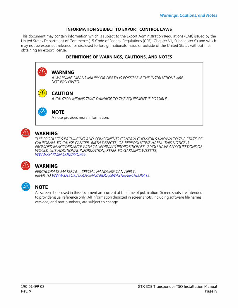
DEFINITIONS OF WARNINGS, CAUTIONS, AND NOTES
WARNINGTHIS PRODUCT’S PACKAGING AND COMPONENTS CONTAIN CHEMICALS KNOWN TO THE STATE OF CALIFORNIA TO CAUSE CANCER, BIRTH DEFECTS, OR REPRODUCTIVE HARM. THIS NOTICE IS PROVIDED IN ACCORDANCE WITH CALIFORNIA'S PROPOSITION 65. IF YOU HAVE ANY QUESTIONS OR WOULD LIKE ADDITIONAL INFORMATION, REFER TO GARMIN’S WEBSITE,WWW.GARMIN.COM/PROP65.
WARNINGPERCHLORATE MATERIAL – SPECIAL HANDLING CAN APPLY.REFER TO WWW.DTSC.CA.GOV./HAZARDOUSWASTE/PERCHLORATE.
NOTEAll screen shots used in this document are current at the time of publication. Screen shots are intended to provide visual reference only. All information depicted in screen shots, including software file names, versions, and part numbers, are subject to change.
WARNINGA WARNING MEANS INJURY OR DEATH IS POSSIBLE IF THE INSTRUCTIONS ARE NOT FOLLOWED.
CAUTIONA CAUTION MEANS THAT DAMAGE TO THE EQUIPMENT IS POSSIBLE.
NOTEA note provides more information.
Table of Contents
1 SYSTEM OVERVIEW ............................................................................................................................................ 1-1
1.1 Scope..................................................................................................................................................... 1-11.2 Equipment Description ........................................................................................................................... 1-21.3 Definitions and Abbreviations................................................................................................................. 1-31.4 ADS-B Capabilities.................................................................................................................................. 1-41.5 FIS-B Capabilities .................................................................................................................................... 1-51.6 TIS System Capabilities ........................................................................................................................... 1-51.7 Interface Summary ................................................................................................................................. 1-61.8 General Specifications ............................................................................................................................ 1-81.9 Transponder Specifications ................................................................................................................... 1-101.10 UAT Receiver Specifications (GTX 345 Only) ......................................................................................... 1-111.11 1090 MHz Receiver Specifications ........................................................................................................ 1-111.12 GPS Specifications (Units with Internal GPS Only).................................................................................. 1-111.13 Power Specifications............................................................................................................................. 1-121.14 Certification ......................................................................................................................................... 1-131.15 License Requirements ........................................................................................................................... 1-161.16 Reference Documents .......................................................................................................................... 1-17
2 LIMITATIONS ..................................................................................................................................................... 2-1
2.1 HSDB Packet Forwarding ........................................................................................................................ 2-12.2 ARINC 429 Data Concentrator Function ................................................................................................. 2-1
3 INSTALLATION OVERVIEW ................................................................................................................................... 3-1
3.1 Introduction ........................................................................................................................................... 3-13.2 Unit Configurations................................................................................................................................ 3-23.3 Accessories Supplied .............................................................................................................................. 3-33.4 Optional Accessories .............................................................................................................................. 3-73.5 Necessary Installation Materials and Accessories Not Supplied ................................................................ 3-93.6 Necessary Special Tools .......................................................................................................................... 3-93.7 Transponder Antenna........................................................................................................................... 3-103.8 GPS Antenna Requirements.................................................................................................................. 3-113.9 Minimum Systems Configuration.......................................................................................................... 3-123.10 GTX Input Source Priority ..................................................................................................................... 3-133.11 ADS-B In Considerations....................................................................................................................... 3-223.12 Bluetooth Considerations (GTX 345R Only)........................................................................................... 3-233.13 Field Enablements ................................................................................................................................ 3-233.14 GPS/SBAS Parameters........................................................................................................................... 3-233.15 Antenna Considerations ....................................................................................................................... 3-243.16 Electrical Bonding................................................................................................................................. 3-273.17 Cabling and Wiring .............................................................................................................................. 3-273.18 Electrical Bonding Considerations ......................................................................................................... 3-273.19 Cooling Requirements and Considerations ........................................................................................... 3-27
4 INSTALLATION PROCEDURE .................................................................................................................................. 4-1
4.1 Wire Harness Installation ........................................................................................................................ 4-14.2 Backshell Assembly Parts ........................................................................................................................ 4-24.3 Shielded Cable Preparation..................................................................................................................... 4-34.4 Connector and Backshell Assembly......................................................................................................... 4-54.5 Configuration Module Installation .......................................................................................................... 4-84.6 Coax Cable Installation......................................................................................................................... 4-104.7 Equipment Rack Installation.................................................................................................................. 4-104.8 Panel and Standard Remote Mount Unit Installation and Removal ........................................................ 4-134.9 Vertical Remote Mount Unit Installation and Removal........................................................................... 4-14
5 CONNECTOR PINOUT INFORMATION ..................................................................................................................... 5-1
190-01499-02 GTX 3X5 Transponder TSO Installation ManualRev. 9 Page v
Table of Contents
5.1 Main Board Connector - J3251............................................................................................................... 5-25.2 ADS-B Board Connector - J3252 (GTX 345 Only) .................................................................................... 5-55.3 Power .................................................................................................................................................... 5-65.4 Lighting Bus ........................................................................................................................................... 5-75.5 Altitude Inputs ....................................................................................................................................... 5-75.6 Discrete I/O ............................................................................................................................................ 5-85.7 Serial Data Interfaces.............................................................................................................................. 5-95.8 Suppression Bus ................................................................................................................................... 5-115.9 OAT Input ............................................................................................................................................ 5-115.10 Audio Output....................................................................................................................................... 5-115.11 Time Mark............................................................................................................................................ 5-115.12 Configuration Module.......................................................................................................................... 5-125.13 USB Interface ....................................................................................................................................... 5-12
6 POST INSTALLATION CONFIGURATION & CHECKOUT ............................................................................................... 6-1
6.1 System Configuration Overview.............................................................................................................. 6-16.2 Mounting, Wiring, and Power Checks .................................................................................................... 6-16.3 Configuration Mode and Settings........................................................................................................... 6-26.4 Audio Settings........................................................................................................................................ 6-36.5 Interfaces ............................................................................................................................................... 6-56.6 Unit Settings ........................................................................................................................................ 6-146.7 Display Pages ....................................................................................................................................... 6-176.8 Sensors ................................................................................................................................................ 6-216.9 ADSB ................................................................................................................................................... 6-276.10 Diagnostics........................................................................................................................................... 6-326.11 Remote Unit Configuration .................................................................................................................. 6-336.12 Ground Check - GPS Reception Check ................................................................................................. 6-336.13 Ground Check - Transponder ............................................................................................................... 6-346.14 Software Installation Procedure ............................................................................................................ 6-34
7 CONTINUED AIRWORTHINESS .............................................................................................................................. 7-1
APPENDIX A DATA FORMATS ................................................................................................................................A-1
A.1 RS-232 Air Data Input Format................................................................................................................. A-1A.2 ARINC 429 Input Formats....................................................................................................................... A-5A.3 ARINC 429 Output Formats.................................................................................................................... A-9
APPENDIX B GTX 3X5 MECHANICAL DRAWINGS ....................................................................................................B-1
APPENDIX C EQUIPMENT COMPATIBILITY AND CONFIGURATION ................................................................................C-1
C.1 ADS-B In Displays ................................................................................................................................... C-2C.2 GPS Sources ........................................................................................................................................... C-4C.3 Altitude Sources ..................................................................................................................................... C-5C.4 Audio Panels .......................................................................................................................................... C-7C.5 Radar Altimeters..................................................................................................................................... C-7C.6 Heading Reference Sources .................................................................................................................... C-8C.7 Traffic Sensors (GTX 345 Only) ............................................................................................................. C-10C.8 Bluetooth ............................................................................................................................................. C-11C.9 Remote Control.................................................................................................................................... C-12C.10 TIS-A Display ........................................................................................................................................ C-13
APPENDIX D INTERCONNECT DRAWINGS .................................................................................................................D-1
APPENDIX E CS-ACNS COMPLIANCE MATRIX ......................................................................................................... E-1
E.1 Elementary Surveillance (ELS) .................................................................................................................. E-1E.2 Enhanced Surveillance (EHS) ................................................................................................................... E-7E.3 ADS-B .................................................................................................................................................... E-9
190-01499-02 GTX 3X5 Transponder TSO Installation ManualRev. 9 Page vi
List of Figures
Figure 3-1 Air Data Discrete Priority Order ....................................................................................................... 3-13Figure 3-2 Pressure Altitude Priority Order ....................................................................................................... 3-14Figure 3-3 Garmin Label on Remote Unit......................................................................................................... 3-23Figure 3-4 GPS Locations of Antennas ............................................................................................................. 3-26Figure 4-1 Shielded Cable Preparation ............................................................................................................... 4-4Figure 4-2 Shield Termination on Backshell Assembly ........................................................................................ 4-6Figure 4-3 Connector and Backshell Assembly ................................................................................................... 4-7Figure 4-4 Configuration Module Installation..................................................................................................... 4-9Figure 4-5 GAE Assembly ................................................................................................................................ 4-12Figure 6-1 Audio Group .................................................................................................................................... 6-3Figure 6-2 Audio Page....................................................................................................................................... 6-3Figure 6-3 Audio Page 2.................................................................................................................................... 6-4Figure 6-4 Audio Page 3.................................................................................................................................... 6-4Figure 6-5 Interface Group ................................................................................................................................ 6-5Figure 6-6 RS-232 Interface Page....................................................................................................................... 6-7Figure 6-7 RS-422 Output Page ......................................................................................................................... 6-8Figure 6-8 A429 In Page.................................................................................................................................... 6-9Figure 6-9 A429 Output Page.......................................................................................................................... 6-10Figure 6-10 HSDB Interface Page ....................................................................................................................... 6-11Figure 6-11 Discrete In Page .............................................................................................................................. 6-12Figure 6-12 Discrete Out Page ........................................................................................................................... 6-13Figure 6-13 Unit Group ..................................................................................................................................... 6-14Figure 6-14 FIS-B Processing Page...................................................................................................................... 6-14Figure 6-15 Altitude and Temperature Units Page.............................................................................................. 6-15Figure 6-16 Installation and VFR ID Page............................................................................................................ 6-15Figure 6-17 Altitude Alert Deviation and Restore Page....................................................................................... 6-16Figure 6-18 Flash Message Indicator Page.......................................................................................................... 6-16Figure 6-19 Bluetooth Page ............................................................................................................................... 6-16Figure 6-20 EHS Page ........................................................................................................................................ 6-16Figure 6-21 Display Group................................................................................................................................. 6-17Figure 6-22 Display Backlight and Minimum Level Page ..................................................................................... 6-18Figure 6-23 Keypad Backlight and Minimum Level Page .................................................................................... 6-18Figure 6-24 Photocell Transition, Slope, and Offset Page ................................................................................... 6-19Figure 6-25 Lighting Bus Input Voltage Page ..................................................................................................... 6-19Figure 6-26 Default Backlight and Contrast Offset Page .................................................................................... 6-20Figure 6-27 Sensor Group ................................................................................................................................. 6-21Figure 6-28 Sensor Page.................................................................................................................................... 6-22Figure 6-29 Altitude Source Page ...................................................................................................................... 6-22Figure 6-30 Source, Integrity, and Offset Page................................................................................................... 6-24Figure 6-31 Internal Alt Encoder Page................................................................................................................ 6-24Figure 6-32 Internal Alt Encoder Adjustment Page............................................................................................. 6-24Figure 6-33 Setting the Yaw Angle.................................................................................................................... 6-25Figure 6-34 Internal AHRS Orientation Page ...................................................................................................... 6-25Figure 6-35 Internal AHRS Calibration Page ....................................................................................................... 6-26Figure 6-36 ADS-B Group.................................................................................................................................. 6-27Figure 6-37 Aircraft Category and Max Airspeed Page....................................................................................... 6-28Figure 6-38 Aircraft Stall Method and Stall Speed Page ..................................................................................... 6-28Figure 6-39 Aircraft Length and Width Page...................................................................................................... 6-29Figure 6-40 1090ES Out Control and UAT Out Remote Control Page ................................................................ 6-29Figure 6-41 1090ES In Capable and UAT In Capable Page ................................................................................. 6-29Figure 6-42 ADS-B In Processing Page ............................................................................................................... 6-30Figure 6-43 Aircraft Tail Number and Address Page ........................................................................................... 6-30Figure 6-44 Allow Pilot to Edit Flight ID Page ..................................................................................................... 6-30Figure 6-45 Default Flight ID and Flight ID Prefix Page ....................................................................................... 6-31
190-01499-02 GTX 3X5 Transponder TSO Installation ManualRev. 9 Page vii
List of Figures
Figure 6-46 Diagnostics Group .......................................................................................................................... 6-32Figure 6-47 Diagnostics Page............................................................................................................................. 6-33Figure B-1 GTX 3X5 GPS Panel Mount Assembly ............................................................................................... B-2Figure B-2 GTX 3X5 GPS Panel Mount Dimensions and Center of Gravity .......................................................... B-3Figure B-3 GTX 3X5R GPS Standard Remote Mount Assembly ........................................................................... B-4Figure B-4 GTX 3X5R GPS Standard Remote Mount Dimensions and Center of Gravity...................................... B-5Figure B-5 GTX 3X5 Vertical Remote Mount ...................................................................................................... B-6Figure B-6 GTX 3X5 Vertical Remote Mount Dimensions and Center of Gravity ................................................. B-7Figure B-7 GTX 3X5R GPS G1000 Mount Rack Assembly................................................................................... B-8Figure B-8 GTX 3X5R GPS G1000 Mounting Rack Dimensions and Center of Gravity......................................... B-9Figure B-9 GTX 3X5 Panel Cutout Detail .......................................................................................................... B-10Figure B-10 GTX 3X5 Connector and Vent Locations ......................................................................................... B-11Figure B-11 Optional Garmin Altitude Encoder .................................................................................................. B-11Figure D-1 GTX 3X5 Power Configuration Typical Interconnect ..........................................................................D-3Figure D-2 GTX 345 - G1000 Interconnect.........................................................................................................D-5Figure D-3 GTX 335 - G1000 Interconnect.........................................................................................................D-7Figure D-4 GTX 3X5 - GNS 480 (CNX80) Interconnect .......................................................................................D-8Figure D-5 GTX 335 - GTN 6XX/7XX Typical Interconnect ..................................................................................D-9Figure D-6 Single/Dual GTX 335 - Single GTN 6XX/7XX Interconnect ...............................................................D-10Figure D-7 GTX 345 - GTN 6XX/7XX Typical Interconnect ................................................................................D-11Figure D-8 GTX 345 - Single/Dual GTN 6XX/7XX Interconnect..........................................................................D-13Figure D-9 GTX 335/345 - GDL 88 Interconnect...............................................................................................D-14Figure D-10 GTX 345 - Traffic Sensor Interconnect.............................................................................................D-15Figure D-11 GTX 345 - Single and Dual 400W/500W Series ...............................................................................D-19Figure D-12 GTX 3X5 - Audio Interconnect ........................................................................................................D-20Figure D-13 GTX 3X5 - Radio Altimeter Interconnect .........................................................................................D-21Figure D-14 GTX 3X5 - AHRS/Heading Source....................................................................................................D-22Figure D-15 GTX 3X5 - Switches and OAT Probe Interconnect ...........................................................................D-23Figure D-16 GTX 3X5 - Altitude Source Interconnect..........................................................................................D-24Figure D-17 GTX 335 - GNS 400W/500W Series Interconnect ............................................................................D-26Figure D-18 GTX 345/345R - Flight Stream Interconnect ....................................................................................D-27Figure D-19 GTX 345 - MX20/GMX 200 Interconnect ........................................................................................D-28Figure D-20 GTX 335 - GDU 620 Interconnect ...................................................................................................D-28
190-01499-02 GTX 3X5 Transponder TSO Installation ManualRev. 9 Page viii

List of Tables
Table 1-1 GTX 3X5 Units ..................................................................................................................................... 1-2Table 1-2 Interface Summary............................................................................................................................... 1-6Table 1-3 BDS Registers....................................................................................................................................... 1-7Table 1-4 Physical Characteristics - Panel Mount Units ......................................................................................... 1-8Table 1-5 Physical Characteristics - Remote Mount Units ..................................................................................... 1-9Table 1-6 Display Specifications ......................................................................................................................... 1-10Table 1-7 GAE Specifications ............................................................................................................................. 1-10Table 1-8 Transponder Specifications................................................................................................................. 1-10Table 1-9 UAT Receiver Specifications................................................................................................................ 1-11Table 1-10 1090 MHz Receiver Specifications ...................................................................................................... 1-11Table 1-11 GPS Receiver Specifications ................................................................................................................ 1-11Table 1-12 Power Specifications .......................................................................................................................... 1-12Table 1-13 TSO Compliance ................................................................................................................................ 1-13Table 1-14 Applicable P/Ns .................................................................................................................................. 1-14Table 1-15 TSO/ETSO Deviations.......................................................................................................................... 1-14Table 1-16 Software Design Assurance Levels ...................................................................................................... 1-15Table 1-17 Complex Hardware Design Assurance Levels ...................................................................................... 1-15Table 1-18 Equipment Authorization ................................................................................................................... 1-16Table 1-19 Garmin Reference Documents............................................................................................................ 1-17Table 1-20 Additional Reference Documents ....................................................................................................... 1-17Table 3-1 GTX 3X5 Configurations ...................................................................................................................... 3-2Table 3-2 Accessories Supplied ............................................................................................................................ 3-3Table 3-3 Pressure Sensor Module ....................................................................................................................... 3-7Table 3-4 GX000 System Rack............................................................................................................................. 3-7Table 3-5 GTX 3X5 Vertical Remote Mount Kits................................................................................................... 3-7Table 3-6 Recommended Crimp Tools ................................................................................................................. 3-9Table 3-7 Acceptable UAT/1090 Antennas ........................................................................................................ 3-10Table 3-8 GNSS Receiver Antennas.................................................................................................................... 3-11Table 3-9 Minimum System Configuration......................................................................................................... 3-12Table 3-10 Compatible ADS-B Traffic/FIS-B Displays ............................................................................................. 3-12Table 3-11 Air Data Select Source Priority ............................................................................................................ 3-14Table 3-12 Barometric Vertical Rate Source Priority .............................................................................................. 3-15Table 3-13 Indicated Airspeed Source Priority ...................................................................................................... 3-15Table 3-14 True Airspeed Source Priority ............................................................................................................. 3-15Table 3-15 Barometric Pressure Setting Source Priority......................................................................................... 3-16Table 3-16 MCP/FCU Selected Altitude Source Priority ......................................................................................... 3-16Table 3-17 Magnetic Heading Source Priority ...................................................................................................... 3-17Table 3-18 True Heading Source Priority .............................................................................................................. 3-17Table 3-19 Static Air Temperature Source Priority ................................................................................................ 3-17Table 3-20 Total Air Temperature Source Priority ................................................................................................. 3-18Table 3-21 Pressure Altitude Source Selection #1................................................................................................. 3-18Table 3-22 Pressure Altitude Source Priority Order #1 .......................................................................................... 3-18Table 3-23 Pressure Altitude Source Priority Order #12 ........................................................................................ 3-19Table 3-24 Baro-Corrected Altitude Source Selection #1...................................................................................... 3-19Table 3-25 Baro-Corrected Altitude Source Priority Order #1 ............................................................................... 3-19Table 3-26 Baro-Corrected Altitude Source Priority Order #2 ............................................................................... 3-19Table 3-27 AHRS Source Priority .......................................................................................................................... 3-20Table 3-28 Airport Reference Points Source Priority ............................................................................................. 3-20Table 3-29 Density Altitude Source Priority .......................................................................................................... 3-20Table 3-30 Height Above Terrain Source Priority .................................................................................................. 3-20Table 3-31 Radio Altitude Source Priority ............................................................................................................. 3-21Table 3-32 Selected Course and Joystick Waypoint Source Priority ....................................................................... 3-21Table 3-33 FMS Selected Altitude Priority ............................................................................................................ 3-21Table 3-34 Magnetic Variation Source Priority ..................................................................................................... 3-21
190-01499-02 GTX 3X5 Transponder TSO Installation ManualRev. 9 Page ix

List of Tables
Table 3-35 EHS Roll Angle Source Priority ............................................................................................................ 3-22Table 3-36 Mach Source Priority .......................................................................................................................... 3-22Table 3-37 Inertial Vertical Rate Source Priority .................................................................................................... 3-22Table 4-1 Backshell Assembly .............................................................................................................................. 4-2Table 4-2 Configuration Module Kit, P/N 011-00979-03...................................................................................... 4-9Table 5-1 J3251 Connector ................................................................................................................................. 5-2Table 5-2 J3252 Connector ................................................................................................................................. 5-5Table 5-3 Power Pins ........................................................................................................................................... 5-6Table 5-4 Power Configuration and Control Inputs.............................................................................................. 5-6Table 5-5 Power Configuration and Power Control Functions .............................................................................. 5-6Table 5-6 Lighting Bus Pins.................................................................................................................................. 5-7Table 5-7 Altitude Inputs ..................................................................................................................................... 5-8Table 5-8 Discrete Inputs and Outputs................................................................................................................. 5-8Table 5-9 RS-232 Inputs and Outputs .................................................................................................................. 5-9Table 5-10 ARINC 429 Inputs and Outputs .......................................................................................................... 5-10Table 5-11 Ethernet Inputs and Outputs .............................................................................................................. 5-10Table 5-12 RS-422 Outputs ................................................................................................................................. 5-10Table 5-13 External Suppression Bus Pin .............................................................................................................. 5-11Table 5-14 OAT Input and Output ....................................................................................................................... 5-11Table 5-15 Audio Inputs and Outputs.................................................................................................................. 5-11Table 5-16 Time Mark Outputs............................................................................................................................ 5-11Table 5-17 Configuration Module Inputs and Outputs ......................................................................................... 5-12Table 5-18 USB Inputs and Outputs..................................................................................................................... 5-12Table 6-1 RS-232 Channel 1 through Channel 3 Selections ................................................................................. 6-6Table 6-2 RS-232 Channel 4 Selections................................................................................................................ 6-7Table 6-3 RS-422 Selections ................................................................................................................................ 6-8Table 6-4 ARINC 429 Inputs ................................................................................................................................ 6-9Table 6-5 ARINC 429 Outputs ........................................................................................................................... 6-10Table 6-6 HSDB Formats.................................................................................................................................... 6-11Table 6-7 Discrete Inputs ................................................................................................................................... 6-12Table 6-8 Discrete Outputs ................................................................................................................................ 6-13Table A-1 AHRS Inputs.........................................................................................................................................A-5Table A-2 ADC Inputs ..........................................................................................................................................A-5Table A-3 ARINC 743A Inputs..............................................................................................................................A-6Table A-4 EFIS Air Data ........................................................................................................................................A-7Table A-5 Flight Control.......................................................................................................................................A-7Table A-6 Heading...............................................................................................................................................A-8Table A-7 Transponder Control Format 1 .............................................................................................................A-8Table A-8 Radio Altitude......................................................................................................................................A-8Table A-9 Traffic Inputs........................................................................................................................................A-9Table A-10 GPS Data Formats ................................................................................................................................A-9Table A-11 Garmin Labels ....................................................................................................................................A-10Table A-12 TAS Output Labels .............................................................................................................................A-10Table A-13 TIS-A Output Labels ...........................................................................................................................A-11Table A-14 Transponder Control Format 1 Labels.................................................................................................A-11Table A-15 Traffic Labels......................................................................................................................................A-12Table C-1 ADS-B In Display ..................................................................................................................................C-2Table C-2 GPS Source ..........................................................................................................................................C-4Table C-3 Altitude Sources...................................................................................................................................C-5Table C-4 Audio Panels........................................................................................................................................C-7Table C-5 Radar Altimeters ..................................................................................................................................C-7Table C-6 Heading Reference Source ...................................................................................................................C-8Table C-7 Traffic Sensors ...................................................................................................................................C-10Table C-8 Bluetooth...........................................................................................................................................C-11
190-01499-02 GTX 3X5 Transponder TSO Installation ManualRev. 9 Page x
List of Tables
Table C-9 Remote Control .................................................................................................................................C-12Table C-10 TIS-A Displays ....................................................................................................................................C-13Table E-1 ELS ...................................................................................................................................................... E-1Table E-2 EHS...................................................................................................................................................... E-7Table E-3 ADS-B.................................................................................................................................................. E-9
190-01499-02 GTX 3X5 Transponder TSO Installation ManualRev. 9 Page xi
System Overview
1 System Overview1.1 Scope ............................................................................................................................................................ 1-11.2 Equipment Description................................................................................................................................... 1-21.3 Definitions and Abbreviations ........................................................................................................................ 1-31.4 ADS-B Capabilities ......................................................................................................................................... 1-4
1.4.1 ADS-B Out .............................................................................................................................................. 1-41.4.2 ADS-B In ................................................................................................................................................. 1-41.4.3 Installation Approval for ADS-B Systems .................................................................................................. 1-4
1.5 FIS-B Capabilities ........................................................................................................................................... 1-51.6 TIS System Capabilities................................................................................................................................... 1-51.7 Interface Summary......................................................................................................................................... 1-61.8 General Specifications.................................................................................................................................... 1-81.9 Transponder Specifications .......................................................................................................................... 1-101.10 UAT Receiver Specifications (GTX 345 Only)................................................................................................. 1-111.11 1090 MHz Receiver Specifications................................................................................................................ 1-111.12 GPS Specifications (Units with Internal GPS Only) ......................................................................................... 1-111.13 Power Specifications .................................................................................................................................... 1-121.14 Certification................................................................................................................................................. 1-13
1.14.1 Non-TSO Functions................................................................................................................................ 1-151.14.2 Design Assurance Levels ........................................................................................................................ 1-151.14.3 Transmitter Grant of Equipment Authorization ...................................................................................... 1-16
1.15 License Requirements .................................................................................................................................. 1-161.16 Reference Documents.................................................................................................................................. 1-17
1.1 ScopeNOTEGarmin recommends installation of the GTX 3X5 by a Garmin–authorized installer. Garmin will not be liable for damages that result from improper or negligent installation of the GTX 3X5 to the extent permitted by law.
Mechanical and electrical information to install the GTX 3X5 into an aircraft is provided in this manual. It is not equivalent to an approved airframe-specific maintenance manual, installation design drawing, or installation data package. The content of this manual assumes use by competent and qualified avionics engineering personnel and/or avionics installation specialist using standard maintenance procedures in accordance with Title 14 of the Code of Federal Regulation and other related accepted procedures.
190-01499-02 GTX 3X5 Transponder TSO Installation ManualRev. 9 Page 1-1
Transponder TSO Installation ManualPage 1-2
System Overview
odel names with an R indicate remote
GTX 345R w/GPS
GTX 345 NV
GTX 345 NV w/GPS
X X X
X X X
X X X
X X X
X X X
X X X
X X X
X X X
X X
X X X
X X X
X X
X X
X X
190-01499-02 GTX 3X5Rev. 9
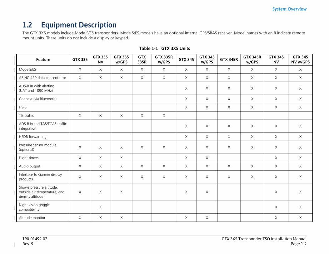
1.2 Equipment DescriptionThe GTX 3X5 models include Mode S/ES transponders. Mode S/ES models have an optional internal GPS/SBAS receiver. Mmount units. These units do not include a display or keypad.
Table 1-1 GTX 3X5 Units
Feature GTX 335 GTX 335 NV
GTX 335 w/GPS
GTX 335R
GTX 335R w/GPS GTX 345 GTX 345
w/GPS GTX 345R
Mode S/ES X X X X X X X X
ARINC 429 data concentrator X X X X X X X X
ADS-B In with alerting (UAT and 1090 MHz)
X X X
Connext (via Bluetooth) X X X
FIS-B X X X
TIS traffic X X X X X
ADS-B In and TAS/TCAS traffic integration
X X X
HSDB forwarding X X X
Pressure sensor module (optional)
X X X X X X X X
Flight timers X X X X X
Audio output X X X X X X X X
Interface to Garmin display products
X X X X X X X X
Shows pressure altitude, outside air temperature, and density altitude
X X X X X
Night vision goggle compatibility
X
Altitude monitor X X X X X
System Overview
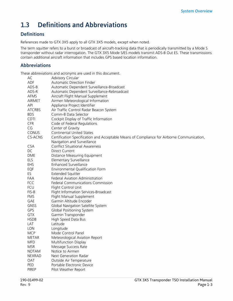
1.3 Definitions and AbbreviationsDefinitions References made to GTX 3X5 apply to all GTX 3X5 models, except when noted.
The term squitter refers to a burst or broadcast of aircraft-tracking data that is periodically transmitted by a Mode S transponder without radar interrogation. The GTX 3X5 Mode S/ES models transmit ADS-B Out ES. These transmissions contain additional aircraft information that includes GPS based location information.
AbbreviationsThese abbreviations and acronyms are used in this document.
AC Advisory CircularADF Automatic Direction FinderADS-B Automatic Dependent Surveillance-BroadcastADS-R Automatic Dependent Surveillance-RebroadcastAFMS Aircraft Flight Manual SupplementAIRMET Airmen Meteorological InformationAPI Appliance Project IdentifierATCRBS Air Traffic Control Radar Beacon SystemBDS Comm-B Data SelectorCDTI Cockpit Display of Traffic InformationCFR Code of Federal RegulationsCG Center of GravityCONUS Continental United StatesCS-ACNS Certification Specification and Acceptable Means of Compliance for Airborne Communication,
Navigation and SurveillanceCSA Conflict Situational AwarenessDC Direct CurrentDME Distance Measuring EquipmentELS Elementary SurveillanceEHS Enhanced SurveillanceEQF Environmental Qualification FormES Extended SquitterFAA Federal Aviation AdministrationFCC Federal Communications CommissionFCU Flight Control UnitFIS-B Flight Information Services-BroadcastFMS Flight Manual SupplementGAE Garmin Altitude EncoderGNSS Global Navigation Satellite SystemGPS Global Positioning SystemGTX Garmin TransponderHSDB High Speed Data BusLAT LatitudeLON LongitudeMCP Mode Control PanelMETAR Meteorological Aviation ReportMFD Multifunction DisplayMSR Message Success RateNOTAM Notice to AirmenNEXRAD Next Generation RadarOAT Outside Air TemperaturePED Portable Electronic DevicePIREP Pilot Weather Report
190-01499-02 GTX 3X5 Transponder TSO Installation ManualRev. 9 Page 1-3

System Overview
POH Pilot Operating HandbookRAIM Receiver Autonomous Integrity MonitoringRFMS Rotorcraft Flight Manual SupplementSATCOM Satellite CommunicationsSBAS Satellite-Based Augmentation SystemSIGMET Significant Meteorological InformationSIL Source Integrity LevelSPI Special Position IndicatorSUA Special Use AirspaceTAF Terminal Area ForecastTAS Traffic Advisory SystemTCAS Traffic Collision Avoidance SystemTIS Traffic Information ServiceTIS-B Traffic Information Service-BroadcastTSO Technical Standard OrderUAT Universal Access TransceiverUHF Ultra-High FrequencyUSB Universal Serial BusVHF Very High FrequencyVSWR Voltage Standing Wave RatioWAAS Wide Area Augmentation System
1.4 ADS-B Capabilities
1.4.1 ADS-B OutThe GTX 335 and GTX 345 include ADS-B Out capabilities when installed with an approved internal or external GPS position source.
1.4.2 ADS-B InFor all ADS-B In data reception capabilities, the GTX 345 includes receivers for both the UAT and the 1090 MHz frequency bands. The GTX 345 receives ADS-B transmissions from other ADS-B Out equipped aircraft, ADS-R, and TIS-B information from ground stations. Traffic information received from these transmissions supply compatible ADS-B In data to CDTIs to show the pilot.
1.4.3 Installation Approval for ADS-B SystemsThe conditions and tests necessary for TSO approval of the GTX 3X5 are minimum performance standards. It is the responsibility of the installer to determine if the aircraft installation conditions are within the TSO standards. TSO units must have separate approval to install in an aircraft. The GTX 3X5 can be installed only in compliance with 14 CFR Part 43 or the applicable airworthiness requirements.
All GTX 3X5 unit functions are design-approved under the TSO. Changes or modifications to any unit that are not approved can void the compliance to necessary regulations and authorization for continued equipment usage.
It is the installer’s responsibility to make sure the ADS-B Out system installation is compliant with 14 CFR 91.227 and to make sure compatibility between the GTX 3X5 and the ADS-B Out equipment. For compatible equipment that is applicable for 14 CFR 91.227-compliant installations in accordance with AC 20-165A refer to Garmin ADS-B Out Compatible Equipment. FIS-B information is for pilot-planning and pilot near-term decisions. The information shown are areas of inclement weather that are out of visual range or are not easily seen.
190-01499-02 GTX 3X5 Transponder TSO Installation ManualRev. 9 Page 1-4
System Overview
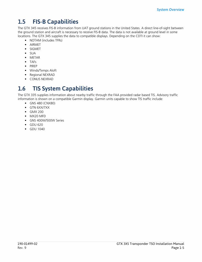
1.5 FIS-B CapabilitiesThe GTX 345 receives FIS-B information from UAT ground stations in the United States. A direct line-of-sight between the ground station and aircraft is necessary to receive FIS-B data. The data is not available at ground level in some locations. The GTX 345 supplies the data to compatible displays. Depending on the CDTI it can show:
• NOTAM (includes TFRs)• AIRMET• SIGMET• SUA• METAR• TAFs• PIREP• Winds/Temps Aloft• Regional NEXRAD• CONUS NEXRAD
1.6 TIS System CapabilitiesThe GTX 335 supplies information about nearby traffic through the FAA provided radar based TIS. Advisory traffic information is shown on a compatible Garmin display. Garmin units capable to show TIS traffic include:
• GNS 480 (CNX80)• GTN 6XX/7XX• GMX 200• MX20 MFD• GNS 400W/500W Series• GDU 620• GDU 1040
190-01499-02 GTX 3X5 Transponder TSO Installation ManualRev. 9 Page 1-5
System Overview
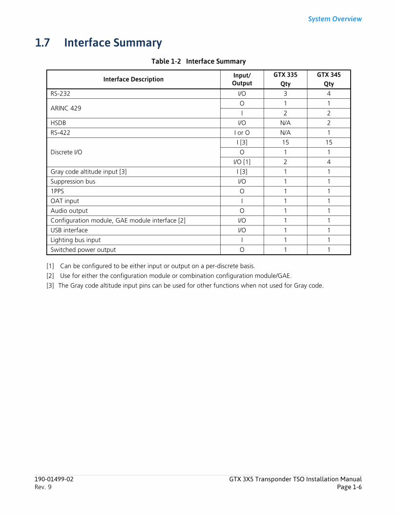
1.7 Interface SummaryTable 1-2 Interface Summary
[1] Can be configured to be either input or output on a per-discrete basis.
[2] Use for either the configuration module or combination configuration module/GAE.
[3] The Gray code altitude input pins can be used for other functions when not used for Gray code.
Interface Description Input/Output
GTX 335Qty
GTX 345Qty
RS-232 I/O 3 4
ARINC 429O 1 1
I 2 2
HSDB I/O N/A 2
RS-422 I or O N/A 1
Discrete I/O
I [3] 15 15
O 1 1
I/O [1] 2 4
Gray code altitude input [3] I [3] 1 1
Suppression bus I/O 1 1
1PPS O 1 1
OAT input I 1 1
Audio output O 1 1
Configuration module, GAE module interface [2] I/O 1 1
USB interface I/O 1 1
Lighting bus input I 1 1
Switched power output O 1 1
190-01499-02 GTX 3X5 Transponder TSO Installation ManualRev. 9 Page 1-6
System Overview
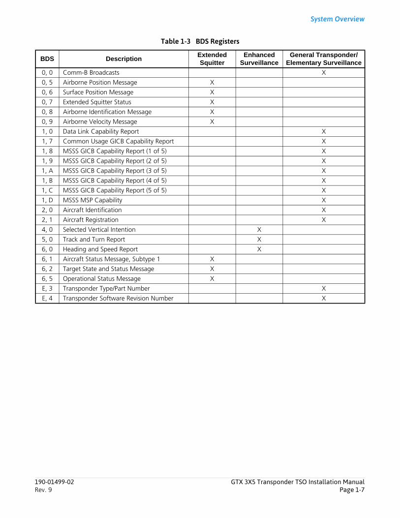
Table 1-3 BDS Registers
BDS DescriptionExtended Squitter
Enhanced Surveillance
General Transponder/Elementary Surveillance
0, 0 Comm-B Broadcasts X
0, 5 Airborne Position Message X
0, 6 Surface Position Message X
0, 7 Extended Squitter Status X
0, 8 Airborne Identification Message X
0, 9 Airborne Velocity Message X
1, 0 Data Link Capability Report X
1, 7 Common Usage GICB Capability Report X
1, 8 MSSS GICB Capability Report (1 of 5) X
1, 9 MSSS GICB Capability Report (2 of 5) X
1, A MSSS GICB Capability Report (3 of 5) X
1, B MSSS GICB Capability Report (4 of 5) X
1, C MSSS GICB Capability Report (5 of 5) X
1, D MSSS MSP Capability X
2, 0 Aircraft Identification X
2, 1 Aircraft Registration X
4, 0 Selected Vertical Intention X
5, 0 Track and Turn Report X
6, 0 Heading and Speed Report X
6, 1 Aircraft Status Message, Subtype 1 X
6, 2 Target State and Status Message X
6, 5 Operational Status Message X
E, 3 Transponder Type/Part Number X
E, 4 Transponder Software Revision Number X
190-01499-02 GTX 3X5 Transponder TSO Installation ManualRev. 9 Page 1-7

System Overview
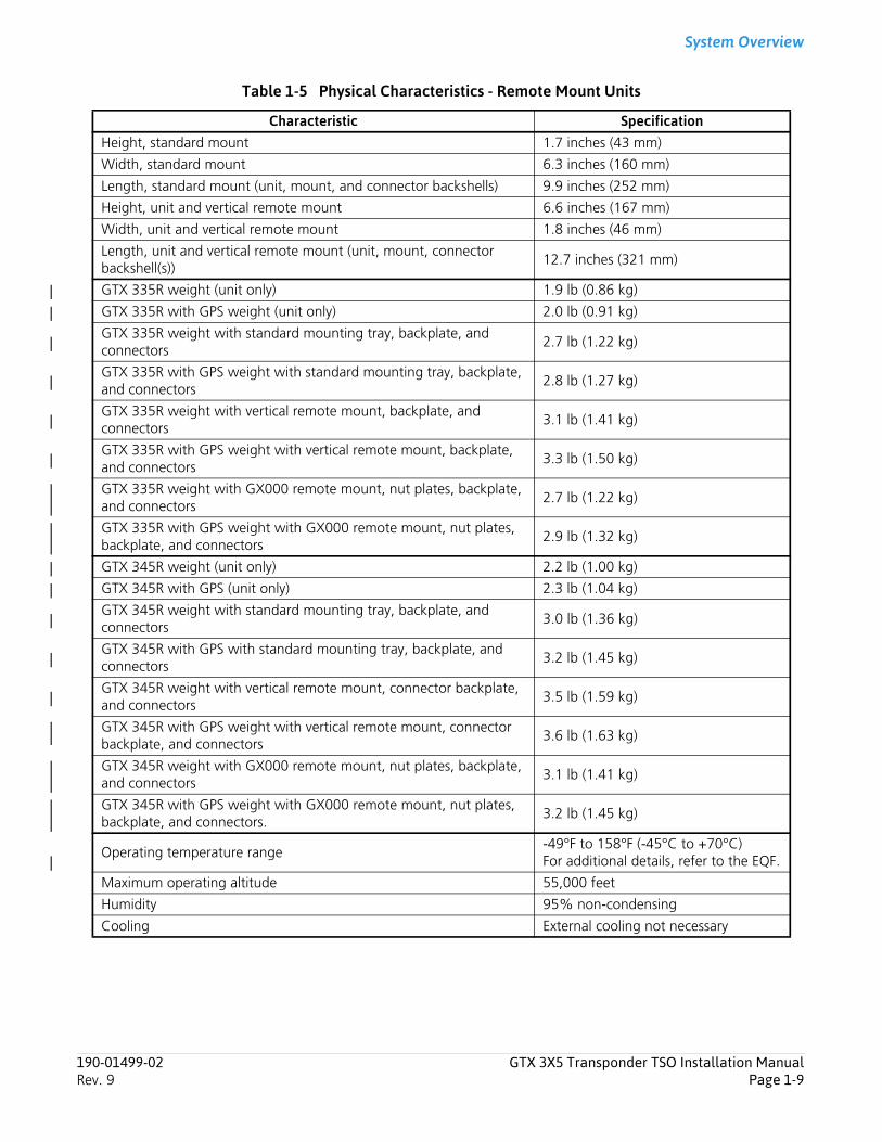
1.8 General SpecificationsIt is the responsibility of the installing agency to obtain EQF necessary for the GTX 3X5.The form, P/N 005-00752-02, is available at the Dealer Resource Center.
Table 1-4 Physical Characteristics - Panel Mount Units
Characteristic SpecificationBezel height 1.65 in. (42 mm)
Bezel width 6.25 in. (159 mm)
Rack height (dimple to dimple) 1.68 in. (43 mm)
Rack width 6.30 in. (160 mm)
Depth behind panel with connectors (measured from face of aircraft panel to rear of connector backshells)
10.07 inches (256 mm)
GTX 335 weight (unit only) 2.1 lb (0.95 kg)
GTX 335 with GPS weight (unit only) 2.2 lb (1.00 kg)
GTX 335 with rack, backplate, and connectors 2.9 lb (1.32 kg)
GTX 335 with GPS with rack, backplate, and connectors 3.0 lb (1.36 kg)
GTX 345 weight (unit only) 2.3 lb (1.04 kg)
GTX 345 with GPS weight (unit only) 2.5 lb (1.13 kg)
GTX 345 with rack, backplate, and connectors 3.2 lb (1.45 kg)
GTX 345 with GPS with rack, backplate, and connectors 3.4 lb (1.54 kg)
Operating temperature range-40°F to 158°F (-40°C to +70°C)For additional details, refer to the EQF.
Maximum operating altitude 55,000 feet
Humidity 95% non-condensing
Cooling External cooling not necessary
190-01499-02 GTX 3X5 Transponder TSO Installation ManualRev. 9 Page 1-8
System Overview
Table 1-5 Physical Characteristics - Remote Mount Units
Characteristic SpecificationHeight, standard mount 1.7 inches (43 mm)
Width, standard mount 6.3 inches (160 mm)
Length, standard mount (unit, mount, and connector backshells) 9.9 inches (252 mm)
Height, unit and vertical remote mount 6.6 inches (167 mm)
Width, unit and vertical remote mount 1.8 inches (46 mm)
Length, unit and vertical remote mount (unit, mount, connector backshell(s))
12.7 inches (321 mm)
GTX 335R weight (unit only) 1.9 lb (0.86 kg)
GTX 335R with GPS weight (unit only) 2.0 lb (0.91 kg)
GTX 335R weight with standard mounting tray, backplate, and connectors
2.7 lb (1.22 kg)
GTX 335R with GPS weight with standard mounting tray, backplate, and connectors
2.8 lb (1.27 kg)
GTX 335R weight with vertical remote mount, backplate, and connectors
3.1 lb (1.41 kg)
GTX 335R with GPS weight with vertical remote mount, backplate, and connectors
3.3 lb (1.50 kg)
GTX 335R weight with GX000 remote mount, nut plates, backplate, and connectors
2.7 lb (1.22 kg)
GTX 335R with GPS weight with GX000 remote mount, nut plates, backplate, and connectors
2.9 lb (1.32 kg)
GTX 345R weight (unit only) 2.2 lb (1.00 kg)
GTX 345R with GPS (unit only) 2.3 lb (1.04 kg)
GTX 345R weight with standard mounting tray, backplate, and connectors
3.0 lb (1.36 kg)
GTX 345R with GPS with standard mounting tray, backplate, and connectors
3.2 lb (1.45 kg)
GTX 345R weight with vertical remote mount, connector backplate, and connectors
3.5 lb (1.59 kg)
GTX 345R with GPS weight with vertical remote mount, connector backplate, and connectors
3.6 lb (1.63 kg)
GTX 345R weight with GX000 remote mount, nut plates, backplate, and connectors
3.1 lb (1.41 kg)
GTX 345R with GPS weight with GX000 remote mount, nut plates, backplate, and connectors.
3.2 lb (1.45 kg)
Operating temperature range-49°F to 158°F (-45°C to +70°C)For additional details, refer to the EQF.
Maximum operating altitude 55,000 feet
Humidity 95% non-condensing
Cooling External cooling not necessary
190-01499-02 GTX 3X5 Transponder TSO Installation ManualRev. 9 Page 1-9
System Overview
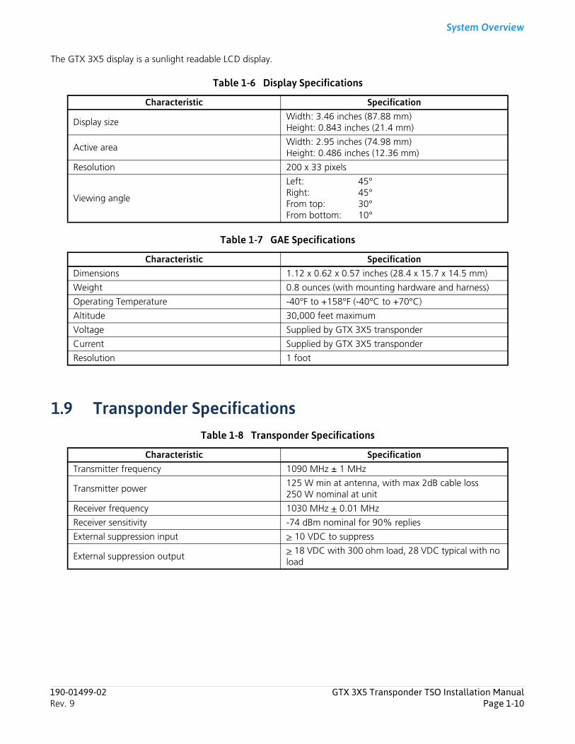
The GTX 3X5 display is a sunlight readable LCD display.
Table 1-6 Display Specifications
Table 1-7 GAE Specifications
1.9 Transponder SpecificationsTable 1-8 Transponder Specifications
Characteristic Specification
Display sizeWidth: 3.46 inches (87.88 mm)Height: 0.843 inches (21.4 mm)
Active areaWidth: 2.95 inches (74.98 mm)Height: 0.486 inches (12.36 mm)
Resolution 200 x 33 pixels
Viewing angle
Left: 45°Right: 45°From top: 30°From bottom: 10°
Characteristic SpecificationDimensions 1.12 x 0.62 x 0.57 inches (28.4 x 15.7 x 14.5 mm)
Weight 0.8 ounces (with mounting hardware and harness)
Operating Temperature -40°F to +158°F (-40°C to +70°C)
Altitude 30,000 feet maximum
Voltage Supplied by GTX 3X5 transponder
Current Supplied by GTX 3X5 transponder
Resolution 1 foot
Characteristic SpecificationTransmitter frequency 1090 MHz ± 1 MHz
Transmitter power125 W min at antenna, with max 2dB cable loss250 W nominal at unit
Receiver frequency 1030 MHz + 0.01 MHz
Receiver sensitivity -74 dBm nominal for 90% replies
External suppression input > 10 VDC to suppress
External suppression output> 18 VDC with 300 ohm load, 28 VDC typical with noload
190-01499-02 GTX 3X5 Transponder TSO Installation ManualRev. 9 Page 1-10
System Overview
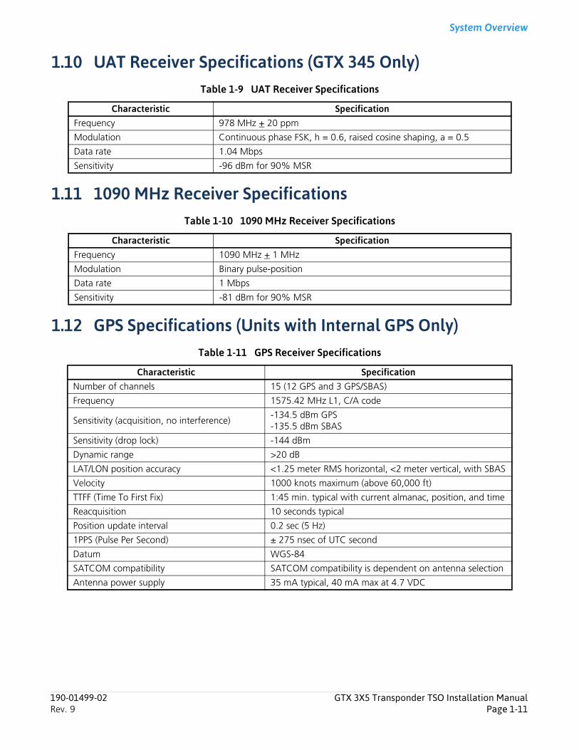
1.10 UAT Receiver Specifications (GTX 345 Only)Table 1-9 UAT Receiver Specifications
1.11 1090 MHz Receiver SpecificationsTable 1-10 1090 MHz Receiver Specifications
1.12 GPS Specifications (Units with Internal GPS Only)Table 1-11 GPS Receiver Specifications
Characteristic SpecificationFrequency 978 MHz + 20 ppm
Modulation Continuous phase FSK, h = 0.6, raised cosine shaping, a = 0.5
Data rate 1.04 Mbps
Sensitivity -96 dBm for 90% MSR
Characteristic SpecificationFrequency 1090 MHz + 1 MHz
Modulation Binary pulse-position
Data rate 1 Mbps
Sensitivity -81 dBm for 90% MSR
Characteristic SpecificationNumber of channels 15 (12 GPS and 3 GPS/SBAS)
Frequency 1575.42 MHz L1, C/A code
Sensitivity (acquisition, no interference)-134.5 dBm GPS-135.5 dBm SBAS
Sensitivity (drop lock) -144 dBm
Dynamic range >20 dB
LAT/LON position accuracy <1.25 meter RMS horizontal, <2 meter vertical, with SBAS
Velocity 1000 knots maximum (above 60,000 ft)
TTFF (Time To First Fix) 1:45 min. typical with current almanac, position, and time
Reacquisition 10 seconds typical
Position update interval 0.2 sec (5 Hz)
1PPS (Pulse Per Second) ± 275 nsec of UTC second
Datum WGS-84
SATCOM compatibility SATCOM compatibility is dependent on antenna selection
Antenna power supply 35 mA typical, 40 mA max at 4.7 VDC
190-01499-02 GTX 3X5 Transponder TSO Installation ManualRev. 9 Page 1-11
System Overview
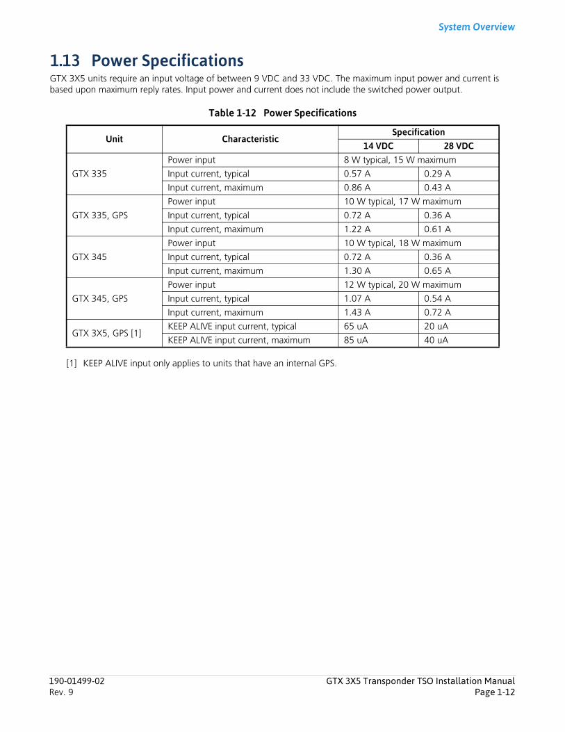
1.13 Power SpecificationsGTX 3X5 units require an input voltage of between 9 VDC and 33 VDC. The maximum input power and current is based upon maximum reply rates. Input power and current does not include the switched power output.
Table 1-12 Power Specifications
[1] KEEP ALIVE input only applies to units that have an internal GPS.
Unit CharacteristicSpecification
14 VDC 28 VDC
GTX 335
Power input 8 W typical, 15 W maximum
Input current, typical 0.57 A 0.29 A
Input current, maximum 0.86 A 0.43 A
GTX 335, GPS
Power input 10 W typical, 17 W maximum
Input current, typical 0.72 A 0.36 A
Input current, maximum 1.22 A 0.61 A
GTX 345
Power input 10 W typical, 18 W maximum
Input current, typical 0.72 A 0.36 A
Input current, maximum 1.30 A 0.65 A
GTX 345, GPS
Power input 12 W typical, 20 W maximum
Input current, typical 1.07 A 0.54 A
Input current, maximum 1.43 A 0.72 A
GTX 3X5, GPS [1]KEEP ALIVE input current, typical 65 uA 20 uA
KEEP ALIVE input current, maximum 85 uA 40 uA
190-01499-02 GTX 3X5 Transponder TSO Installation ManualRev. 9 Page 1-12
System Overview
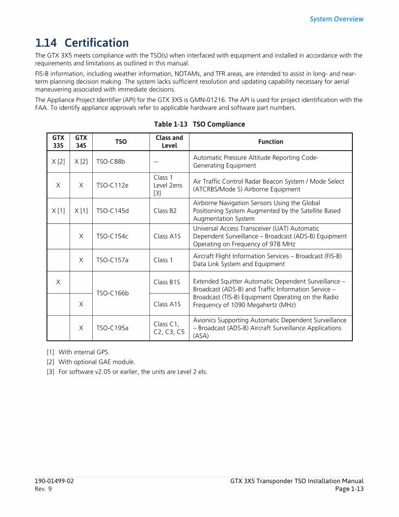
1.14 CertificationThe GTX 3X5 meets compliance with the TSO(s) when interfaced with equipment and installed in accordance with the requirements and limitations as outlined in this manual.
FIS-B information, including weather information, NOTAMs, and TFR areas, are intended to assist in long- and near-term planning decision making. The system lacks sufficient resolution and updating capability necessary for aerial maneuvering associated with immediate decisions.
The Appliance Project Identifier (API) for the GTX 3X5 is GMN-01216. The API is used for project identification with the FAA. To identify appliance approvals refer to applicable hardware and software part numbers.
Table 1-13 TSO Compliance
[1] With internal GPS.
[2] With optional GAE module.
[3] For software v2.05 or earlier, the units are Level 2 els.
GTX 335
GTX345 TSO Class and
Level Function
X [2] X [2] TSO-C88b --Automatic Pressure Altitude Reporting Code-Generating Equipment
X X TSO-C112eClass 1Level 2ens [3]
Air Traffic Control Radar Beacon System / Mode Select (ATCRBS/Mode S) Airborne Equipment
X [1] X [1] TSO-C145d Class B2Airborne Navigation Sensors Using the Global Positioning System Augmented by the Satellite Based Augmentation System
X TSO-C154c Class A1SUniversal Access Transceiver (UAT) Automatic Dependent Surveillance – Broadcast (ADS-B) Equipment Operating on Frequency of 978 MHz
X TSO-C157a Class 1Aircraft Flight Information Services – Broadcast (FIS-B) Data Link System and Equipment
X
TSO-C166b
Class B1S Extended Squitter Automatic Dependent Surveillance – Broadcast (ADS-B) and Traffic Information Service – Broadcast (TIS-B) Equipment Operating on the Radio Frequency of 1090 Megahertz (MHz)X Class A1S
X TSO-C195aClass C1, C2, C3, C5
Avionics Supporting Automatic Dependent Surveillance – Broadcast (ADS-B) Aircraft Surveillance Applications (ASA)
190-01499-02 GTX 3X5 Transponder TSO Installation ManualRev. 9 Page 1-13
System Overview
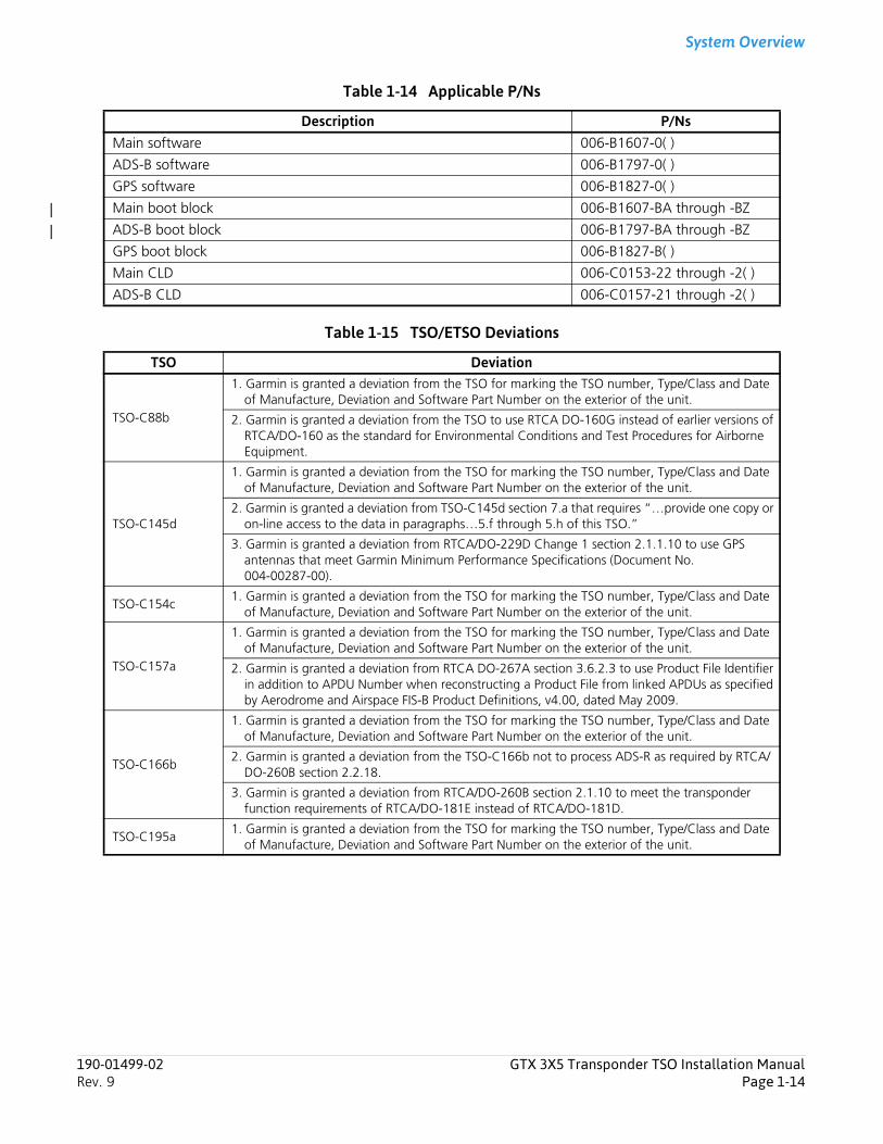
Table 1-14 Applicable P/Ns
Table 1-15 TSO/ETSO Deviations
Description P/NsMain software 006-B1607-0( )
ADS-B software 006-B1797-0( )
GPS software 006-B1827-0( )
Main boot block 006-B1607-BA through -BZ
ADS-B boot block 006-B1797-BA through -BZ
GPS boot block 006-B1827-B( )
Main CLD 006-C0153-22 through -2( )
ADS-B CLD 006-C0157-21 through -2( )
TSO Deviation
TSO-C88b
1. Garmin is granted a deviation from the TSO for marking the TSO number, Type/Class and Date of Manufacture, Deviation and Software Part Number on the exterior of the unit.
2. Garmin is granted a deviation from the TSO to use RTCA DO-160G instead of earlier versions of RTCA/DO-160 as the standard for Environmental Conditions and Test Procedures for Airborne Equipment.
TSO-C145d
1. Garmin is granted a deviation from the TSO for marking the TSO number, Type/Class and Date of Manufacture, Deviation and Software Part Number on the exterior of the unit.
2. Garmin is granted a deviation from TSO-C145d section 7.a that requires “…provide one copy or on-line access to the data in paragraphs…5.f through 5.h of this TSO.”
3. Garmin is granted a deviation from RTCA/DO-229D Change 1 section 2.1.1.10 to use GPS antennas that meet Garmin Minimum Performance Specifications (Document No. 004-00287-00).
TSO-C154c1. Garmin is granted a deviation from the TSO for marking the TSO number, Type/Class and Date
of Manufacture, Deviation and Software Part Number on the exterior of the unit.
TSO-C157a
1. Garmin is granted a deviation from the TSO for marking the TSO number, Type/Class and Date of Manufacture, Deviation and Software Part Number on the exterior of the unit.
2. Garmin is granted a deviation from RTCA DO-267A section 3.6.2.3 to use Product File Identifier in addition to APDU Number when reconstructing a Product File from linked APDUs as specified by Aerodrome and Airspace FIS-B Product Definitions, v4.00, dated May 2009.
TSO-C166b
1. Garmin is granted a deviation from the TSO for marking the TSO number, Type/Class and Date of Manufacture, Deviation and Software Part Number on the exterior of the unit.
2. Garmin is granted a deviation from the TSO-C166b not to process ADS-R as required by RTCA/DO-260B section 2.2.18.
3. Garmin is granted a deviation from RTCA/DO-260B section 2.1.10 to meet the transponder function requirements of RTCA/DO-181E instead of RTCA/DO-181D.
TSO-C195a1. Garmin is granted a deviation from the TSO for marking the TSO number, Type/Class and Date
of Manufacture, Deviation and Software Part Number on the exterior of the unit.
190-01499-02 GTX 3X5 Transponder TSO Installation ManualRev. 9 Page 1-14
System Overview
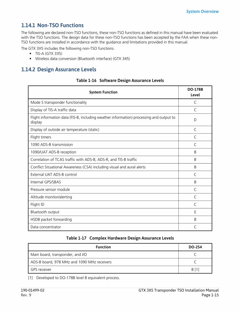
1.14.1 Non-TSO FunctionsThe following are declared non-TSO functions, these non-TSO functions as defined in this manual have been evaluated with the TSO functions. The design data for these non-TSO functions has been accepted by the FAA when these non-TSO functions are installed in accordance with the guidance and limitations provided in this manual.
The GTX 3X5 includes the following non-TSO functions.• TIS-A (GTX 335)• Wireless data conversion (Bluetooth interface) (GTX 345)
1.14.2 Design Assurance Levels
Table 1-16 Software Design Assurance Levels
Table 1-17 Complex Hardware Design Assurance Levels
[1] Developed to DO-178B level B equivalent process.
System FunctionDO-178B
Level
Mode S transponder functionality C
Display of TIS-A traffic data C
Flight information data (FIS-B, including weather information) processing and output to display
D
Display of outside air temperature (static) C
Flight timers C
1090 ADS-B transmission C
1090/UAT ADS-B reception B
Correlation of TCAS traffic with ADS-B, ADS-R, and TIS-B traffic B
Conflict Situational Awareness (CSA) including visual and aural alerts B
External UAT ADS-B control C
Internal GPS/SBAS B
Pressure sensor module C
Altitude monitor/alerting C
Flight ID C
Bluetooth output E
HSDB packet forwarding B
Data concentrator C
Function DO-254
Main board, transponder, and I/O C
ADS-B board, 978 MHz and 1090 MHz receivers C
GPS receiver B [1]
190-01499-02 GTX 3X5 Transponder TSO Installation ManualRev. 9 Page 1-15
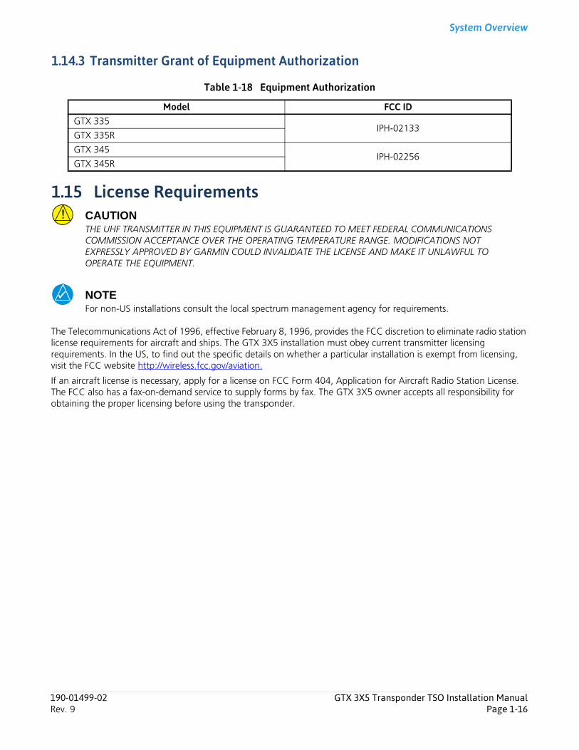
System Overview
1.14.3 Transmitter Grant of Equipment Authorization
Table 1-18 Equipment Authorization
1.15 License RequirementsCAUTIONTHE UHF TRANSMITTER IN THIS EQUIPMENT IS GUARANTEED TO MEET FEDERAL COMMUNICATIONS COMMISSION ACCEPTANCE OVER THE OPERATING TEMPERATURE RANGE. MODIFICATIONS NOT EXPRESSLY APPROVED BY GARMIN COULD INVALIDATE THE LICENSE AND MAKE IT UNLAWFUL TO OPERATE THE EQUIPMENT.
NOTEFor non-US installations consult the local spectrum management agency for requirements.
The Telecommunications Act of 1996, effective February 8, 1996, provides the FCC discretion to eliminate radio station license requirements for aircraft and ships. The GTX 3X5 installation must obey current transmitter licensing requirements. In the US, to find out the specific details on whether a particular installation is exempt from licensing, visit the FCC website http://wireless.fcc.gov/aviation.
If an aircraft license is necessary, apply for a license on FCC Form 404, Application for Aircraft Radio Station License. The FCC also has a fax-on-demand service to supply forms by fax. The GTX 3X5 owner accepts all responsibility for obtaining the proper licensing before using the transponder.
Model FCC IDGTX 335
IPH-02133GTX 335R
GTX 345IPH-02256
GTX 345R
190-01499-02 GTX 3X5 Transponder TSO Installation ManualRev. 9 Page 1-16
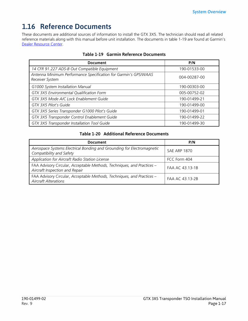
System Overview
1.16 Reference DocumentsThese documents are additional sources of information to install the GTX 3X5. The technician should read all related reference materials along with this manual before unit installation. The documents in table 1-19 are found at Garmin’s Dealer Resource Center.
Table 1-19 Garmin Reference Documents
Table 1-20 Additional Reference Documents
Document P/N14 CFR 91.227 ADS-B Out Compatible Equipment 190-01533-00Antenna Minimum Performance Specification for Garmin’s GPS/WAAS Receiver System 004-00287-00
G1000 System Installation Manual 190-00303-00
GTX 3X5 Environmental Qualification Form 005-00752-02
GTX 3X5 Mode A/C Lock Enablement Guide 190-01499-21
GTX 3X5 Pilot’s Guide 190-01499-00
GTX 3X5 Series Transponder G1000 Pilot’s Guide 190-01499-01
GTX 3X5 Transponder Control Enablement Guide 190-01499-22
GTX 3X5 Transponder Installation Tool Guide 190-01499-30
Document P/NAerospace Systems Electrical Bonding and Grounding for Electromagnetic Compatibility and Safety
SAE ARP 1870
Application for Aircraft Radio Station License FCC Form 404
FAA Advisory Circular, Acceptable Methods, Techniques, and Practices – Aircraft Inspection and Repair
FAA AC 43.13-1B
FAA Advisory Circular, Acceptable Methods, Techniques, and Practices – Aircraft Alterations
FAA AC 43.13-2B
190-01499-02 GTX 3X5 Transponder TSO Installation ManualRev. 9 Page 1-17
Limitations
190-01499-02 GTX 3X5 Transponder TSO Installation ManualRev. 9 Page 2-1
2 Limitations2.1 HSDB Packet Forwarding ............................................................................................................................... 2-12.2 ARINC 429 Data Concentrator Function......................................................................................................... 2-1
The GTX 3X5 meets the minimum performance and quality control standards that are necessary by the TSOs in section 1.14. Installation of the GTX 3X5 requires separate approval.
2.1 HSDB Packet ForwardingThe GTX 345 HSDB interface is not approved for forwarding data whose failure condition for loss or malfunction is classified as hazardous or catastrophic.
2.2 ARINC 429 Data Concentrator FunctionARINC 429 data from the GTX 3X5 must not be used for any function whose associated failure is classified as hazardous or catastrophic.
Installation Overview
3 Installation Overview3.1 Introduction................................................................................................................................................... 3-13.2 Unit Configurations ....................................................................................................................................... 3-23.3 Accessories Supplied...................................................................................................................................... 3-33.4 Optional Accessories...................................................................................................................................... 3-7
3.4.1 GAE ........................................................................................................................................................ 3-73.4.2 GX000 System Rack ................................................................................................................................ 3-73.4.3 GTX 3X5 Vertical Remote Mount............................................................................................................. 3-73.4.4 GPS Antenna........................................................................................................................................... 3-8
3.5 Necessary Installation Materials and Accessories Not Supplied........................................................................ 3-93.6 Necessary Special Tools.................................................................................................................................. 3-93.7 Transponder Antenna .................................................................................................................................. 3-103.8 GPS Antenna Requirements ......................................................................................................................... 3-113.9 Minimum Systems Configuration ................................................................................................................. 3-123.10 GTX Input Source Priority............................................................................................................................. 3-133.11 ADS-B In Considerations .............................................................................................................................. 3-223.12 Bluetooth Considerations (GTX 345R Only) .................................................................................................. 3-233.13 Field Enablements........................................................................................................................................ 3-233.14 GPS/SBAS Parameters .................................................................................................................................. 3-233.15 Antenna Considerations .............................................................................................................................. 3-24
3.15.1 Transponder Antenna............................................................................................................................ 3-243.15.2 GPS Antenna......................................................................................................................................... 3-25
3.16 Electrical Bonding ........................................................................................................................................ 3-273.17 Cabling and Wiring...................................................................................................................................... 3-273.18 Electrical Bonding Considerations ................................................................................................................ 3-273.19 Cooling Requirements and Considerations................................................................................................... 3-27
3.1 IntroductionEquipment information to install the GTX 3X5 and optional accessories is in this section. Cabling is made by the installing agency to fit each particular aircraft. Always follow permitted avionics installation procedures as outlined in AC 43.13-1B and AC 43.13-2B or later FAA approved revisions.
190-01499-02 GTX 3X5 Transponder TSO Installation ManualRev. 9 Page 3-1
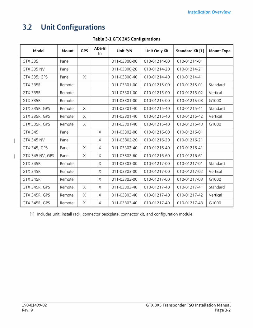
Installation Overview
3.2 Unit ConfigurationsTable 3-1 GTX 3X5 Configurations
[1] Includes unit, install rack, connector backplate, connector kit, and configuration module.
Model Mount GPS ADS-B In Unit P/N Unit Only Kit Standard Kit [1] Mount Type
GTX 335 Panel 011-03300-00 010-01214-00 010-01214-01
GTX 335 NV Panel 011-03300-20 010-01214-20 010-01214-21
GTX 335, GPS Panel X 011-03300-40 010-01214-40 010-01214-41
GTX 335R Remote 011-03301-00 010-01215-00 010-01215-01 Standard
GTX 335R Remote 011-03301-00 010-01215-00 010-01215-02 Vertical
GTX 335R Remote 011-03301-00 010-01215-00 010-01215-03 G1000
GTX 335R, GPS Remote X 011-03301-40 010-01215-40 010-01215-41 Standard
GTX 335R, GPS Remote X 011-03301-40 010-01215-40 010-01215-42 Vertical
GTX 335R, GPS Remote X 011-03301-40 010-01215-40 010-01215-43 G1000
GTX 345 Panel X 011-03302-00 010-01216-00 010-01216-01
GTX 345 NV Panel X 011-03302-20 010-01216-20 010-01216-21
GTX 345, GPS Panel X X 011-03302-40 010-01216-40 010-01216-41
GTX 345 NV, GPS Panel X X 011-03302-60 010-01216-60 010-01216-61
GTX 345R Remote X 011-03303-00 010-01217-00 010-01217-01 Standard
GTX 345R Remote X 011-03303-00 010-01217-00 010-01217-02 Vertical
GTX 345R Remote X 011-03303-00 010-01217-00 010-01217-03 G1000
GTX 345R, GPS Remote X X 011-03303-40 010-01217-40 010-01217-41 Standard
GTX 345R, GPS Remote X X 011-03303-40 010-01217-40 010-01217-42 Vertical
GTX 345R, GPS Remote X X 011-03303-40 010-01217-40 010-01217-43 G1000
190-01499-02 GTX 3X5 Transponder TSO Installation ManualRev. 9 Page 3-2
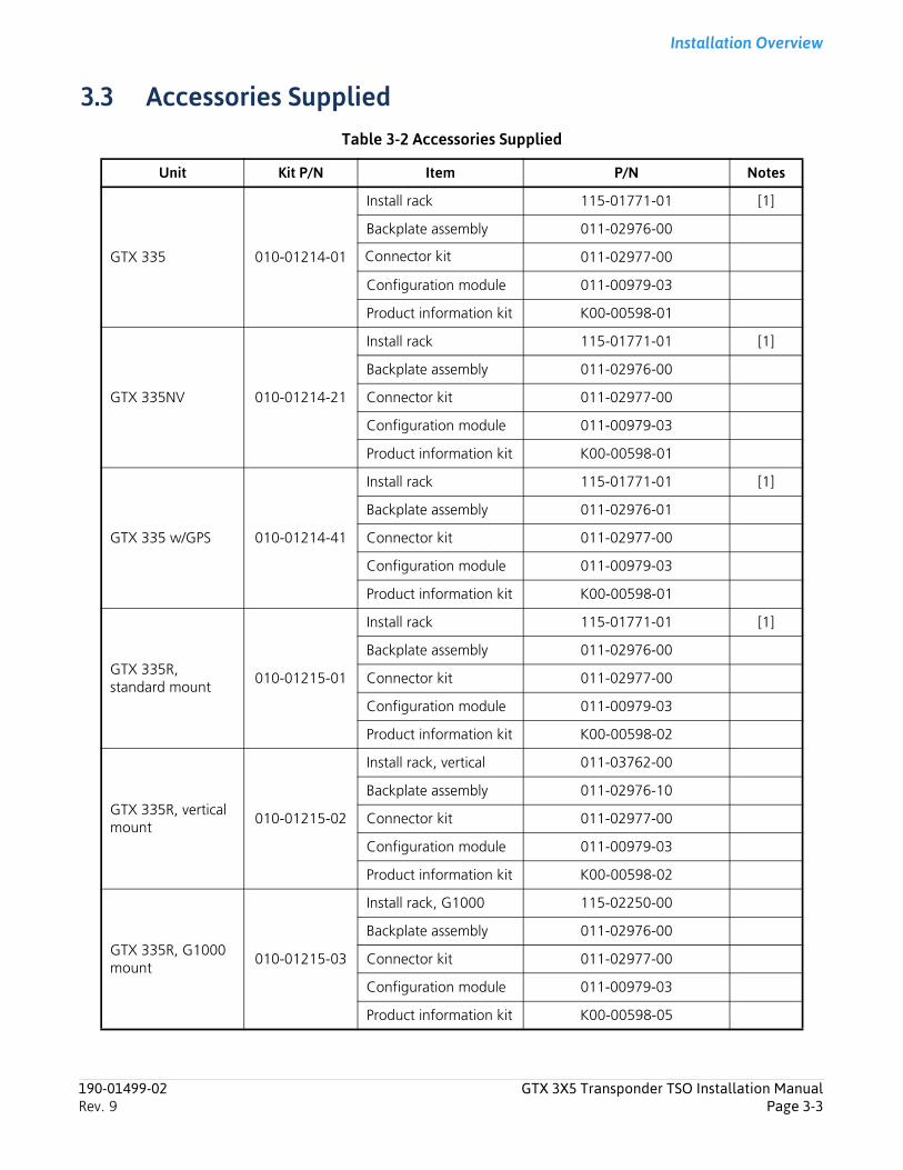
Installation Overview
3.3 Accessories SuppliedTable 3-2 Accessories Supplied
Unit Kit P/N Item P/N Notes
GTX 335 010-01214-01
Install rack 115-01771-01 [1]
Backplate assembly 011-02976-00
Connector kit 011-02977-00
Configuration module 011-00979-03
Product information kit K00-00598-01
GTX 335NV 010-01214-21
Install rack 115-01771-01 [1]
Backplate assembly 011-02976-00
Connector kit 011-02977-00
Configuration module 011-00979-03
Product information kit K00-00598-01
GTX 335 w/GPS 010-01214-41
Install rack 115-01771-01 [1]
Backplate assembly 011-02976-01
Connector kit 011-02977-00
Configuration module 011-00979-03
Product information kit K00-00598-01
GTX 335R, standard mount
010-01215-01
Install rack 115-01771-01 [1]
Backplate assembly 011-02976-00
Connector kit 011-02977-00
Configuration module 011-00979-03
Product information kit K00-00598-02
GTX 335R, vertical mount
010-01215-02
Install rack, vertical 011-03762-00
Backplate assembly 011-02976-10
Connector kit 011-02977-00
Configuration module 011-00979-03
Product information kit K00-00598-02
GTX 335R, G1000 mount
010-01215-03
Install rack, G1000 115-02250-00
Backplate assembly 011-02976-00
Connector kit 011-02977-00
Configuration module 011-00979-03
Product information kit K00-00598-05
190-01499-02 GTX 3X5 Transponder TSO Installation ManualRev. 9 Page 3-3
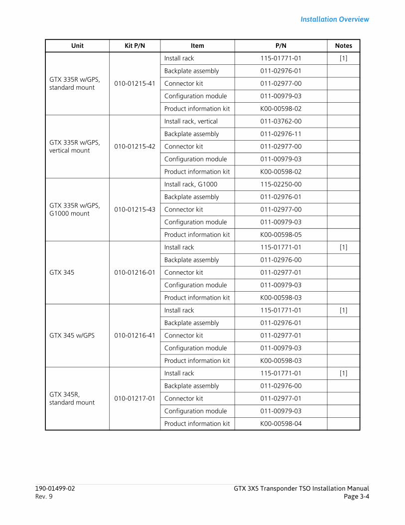
Installation Overview
GTX 335R w/GPS, standard mount
010-01215-41
Install rack 115-01771-01 [1]
Backplate assembly 011-02976-01
Connector kit 011-02977-00
Configuration module 011-00979-03
Product information kit K00-00598-02
GTX 335R w/GPS, vertical mount
010-01215-42
Install rack, vertical 011-03762-00
Backplate assembly 011-02976-11
Connector kit 011-02977-00
Configuration module 011-00979-03
Product information kit K00-00598-02
GTX 335R w/GPS, G1000 mount
010-01215-43
Install rack, G1000 115-02250-00
Backplate assembly 011-02976-01
Connector kit 011-02977-00
Configuration module 011-00979-03
Product information kit K00-00598-05
GTX 345 010-01216-01
Install rack 115-01771-01 [1]
Backplate assembly 011-02976-00
Connector kit 011-02977-01
Configuration module 011-00979-03
Product information kit K00-00598-03
GTX 345 w/GPS 010-01216-41
Install rack 115-01771-01 [1]
Backplate assembly 011-02976-01
Connector kit 011-02977-01
Configuration module 011-00979-03
Product information kit K00-00598-03
GTX 345R, standard mount
010-01217-01
Install rack 115-01771-01 [1]
Backplate assembly 011-02976-00
Connector kit 011-02977-01
Configuration module 011-00979-03
Product information kit K00-00598-04
Unit Kit P/N Item P/N Notes
190-01499-02 GTX 3X5 Transponder TSO Installation ManualRev. 9 Page 3-4
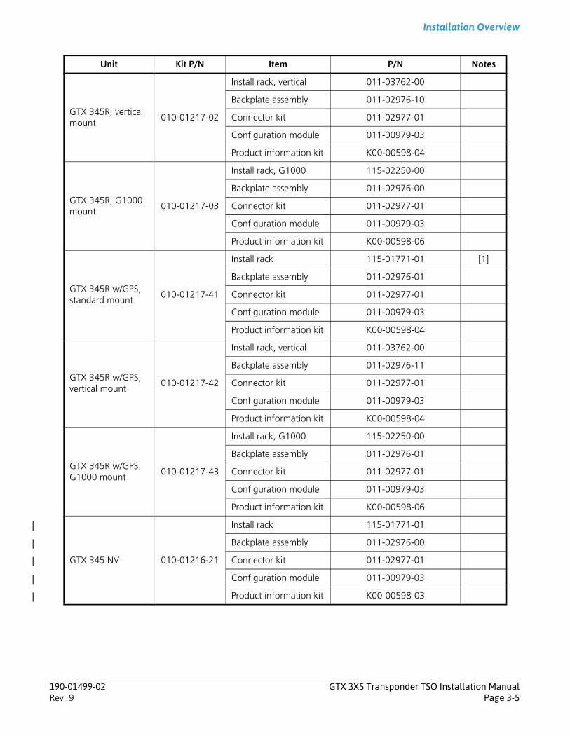
Installation Overview
GTX 345R, vertical mount
010-01217-02
Install rack, vertical 011-03762-00
Backplate assembly 011-02976-10
Connector kit 011-02977-01
Configuration module 011-00979-03
Product information kit K00-00598-04
GTX 345R, G1000 mount
010-01217-03
Install rack, G1000 115-02250-00
Backplate assembly 011-02976-00
Connector kit 011-02977-01
Configuration module 011-00979-03
Product information kit K00-00598-06
GTX 345R w/GPS, standard mount
010-01217-41
Install rack 115-01771-01 [1]
Backplate assembly 011-02976-01
Connector kit 011-02977-01
Configuration module 011-00979-03
Product information kit K00-00598-04
GTX 345R w/GPS, vertical mount
010-01217-42
Install rack, vertical 011-03762-00
Backplate assembly 011-02976-11
Connector kit 011-02977-01
Configuration module 011-00979-03
Product information kit K00-00598-04
GTX 345R w/GPS, G1000 mount
010-01217-43
Install rack, G1000 115-02250-00
Backplate assembly 011-02976-01
Connector kit 011-02977-01
Configuration module 011-00979-03
Product information kit K00-00598-06
GTX 345 NV 010-01216-21
Install rack 115-01771-01
Backplate assembly 011-02976-00
Connector kit 011-02977-01
Configuration module 011-00979-03
Product information kit K00-00598-03
Unit Kit P/N Item P/N Notes
190-01499-02 GTX 3X5 Transponder TSO Installation ManualRev. 9 Page 3-5
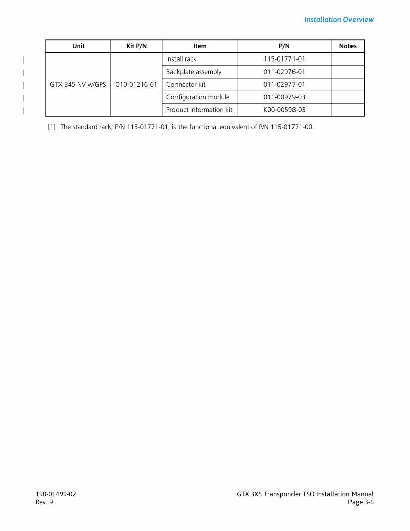
Installation Overview
[1] The standard rack, P/N 115-01771-01, is the functional equivalent of P/N 115-01771-00.
GTX 345 NV w/GPS 010-01216-61
Install rack 115-01771-01
Backplate assembly 011-02976-01
Connector kit 011-02977-01
Configuration module 011-00979-03
Product information kit K00-00598-03
Unit Kit P/N Item P/N Notes
190-01499-02 GTX 3X5 Transponder TSO Installation ManualRev. 9 Page 3-6
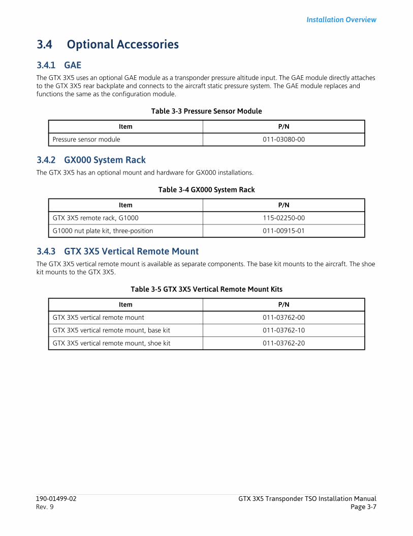
Installation Overview
3.4 Optional Accessories
3.4.1 GAEThe GTX 3X5 uses an optional GAE module as a transponder pressure altitude input. The GAE module directly attaches to the GTX 3X5 rear backplate and connects to the aircraft static pressure system. The GAE module replaces and functions the same as the configuration module.
Table 3-3 Pressure Sensor Module
3.4.2 GX000 System RackThe GTX 3X5 has an optional mount and hardware for GX000 installations.
Table 3-4 GX000 System Rack
3.4.3 GTX 3X5 Vertical Remote MountThe GTX 3X5 vertical remote mount is available as separate components. The base kit mounts to the aircraft. The shoe kit mounts to the GTX 3X5.
Table 3-5 GTX 3X5 Vertical Remote Mount Kits
Item P/N
Pressure sensor module 011-03080-00
Item P/N
GTX 3X5 remote rack, G1000 115-02250-00
G1000 nut plate kit, three-position 011-00915-01
Item P/N
GTX 3X5 vertical remote mount 011-03762-00
GTX 3X5 vertical remote mount, base kit 011-03762-10
GTX 3X5 vertical remote mount, shoe kit 011-03762-20
190-01499-02 GTX 3X5 Transponder TSO Installation ManualRev. 9 Page 3-7
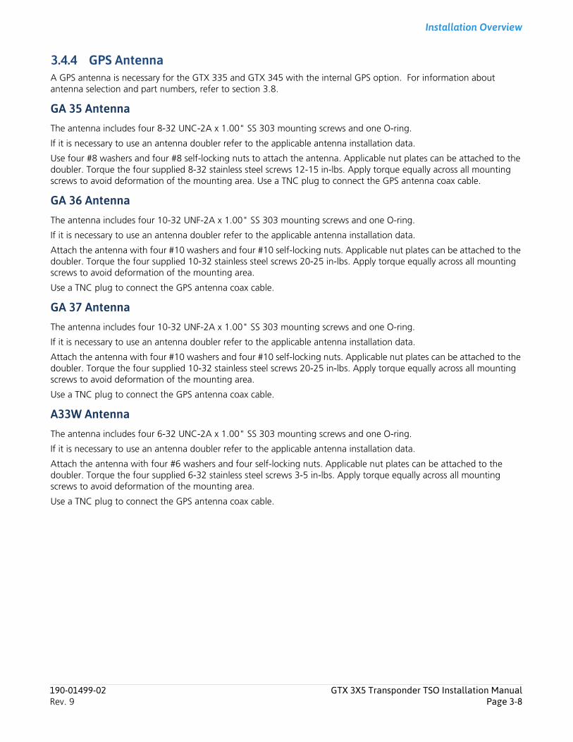
Installation Overview
3.4.4 GPS AntennaA GPS antenna is necessary for the GTX 335 and GTX 345 with the internal GPS option. For information about antenna selection and part numbers, refer to section 3.8.
GA 35 AntennaThe antenna includes four 8-32 UNC-2A x 1.00" SS 303 mounting screws and one O-ring.
If it is necessary to use an antenna doubler refer to the applicable antenna installation data.
Use four #8 washers and four #8 self-locking nuts to attach the antenna. Applicable nut plates can be attached to the doubler. Torque the four supplied 8-32 stainless steel screws 12-15 in-lbs. Apply torque equally across all mounting screws to avoid deformation of the mounting area. Use a TNC plug to connect the GPS antenna coax cable.
GA 36 AntennaThe antenna includes four 10-32 UNF-2A x 1.00" SS 303 mounting screws and one O-ring.
If it is necessary to use an antenna doubler refer to the applicable antenna installation data.
Attach the antenna with four #10 washers and four #10 self-locking nuts. Applicable nut plates can be attached to the doubler. Torque the four supplied 10-32 stainless steel screws 20-25 in-lbs. Apply torque equally across all mounting screws to avoid deformation of the mounting area.
Use a TNC plug to connect the GPS antenna coax cable.
GA 37 AntennaThe antenna includes four 10-32 UNF-2A x 1.00" SS 303 mounting screws and one O-ring.
If it is necessary to use an antenna doubler refer to the applicable antenna installation data.
Attach the antenna with four #10 washers and four #10 self-locking nuts. Applicable nut plates can be attached to the doubler. Torque the four supplied 10-32 stainless steel screws 20-25 in-lbs. Apply torque equally across all mounting screws to avoid deformation of the mounting area.
Use a TNC plug to connect the GPS antenna coax cable.
A33W AntennaThe antenna includes four 6-32 UNC-2A x 1.00" SS 303 mounting screws and one O-ring.
If it is necessary to use an antenna doubler refer to the applicable antenna installation data.
Attach the antenna with four #6 washers and four self-locking nuts. Applicable nut plates can be attached to the doubler. Torque the four supplied 6-32 stainless steel screws 3-5 in-lbs. Apply torque equally across all mounting screws to avoid deformation of the mounting area.
Use a TNC plug to connect the GPS antenna coax cable.
190-01499-02 GTX 3X5 Transponder TSO Installation ManualRev. 9 Page 3-8
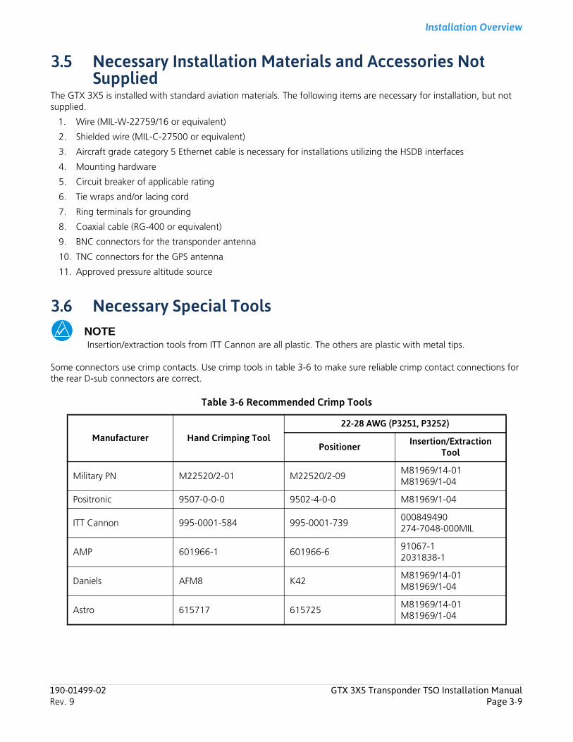
Installation Overview
3.5 Necessary Installation Materials and Accessories Not Supplied
The GTX 3X5 is installed with standard aviation materials. The following items are necessary for installation, but not supplied.
1. Wire (MIL-W-22759/16 or equivalent)
2. Shielded wire (MIL-C-27500 or equivalent)
3. Aircraft grade category 5 Ethernet cable is necessary for installations utilizing the HSDB interfaces
4. Mounting hardware
5. Circuit breaker of applicable rating
6. Tie wraps and/or lacing cord
7. Ring terminals for grounding
8. Coaxial cable (RG-400 or equivalent)
9. BNC connectors for the transponder antenna
10. TNC connectors for the GPS antenna
11. Approved pressure altitude source
3.6 Necessary Special Tools NOTEInsertion/extraction tools from ITT Cannon are all plastic. The others are plastic with metal tips.
Some connectors use crimp contacts. Use crimp tools in table 3-6 to make sure reliable crimp contact connections for the rear D-sub connectors are correct.
Table 3-6 Recommended Crimp Tools
Manufacturer Hand Crimping Tool22-28 AWG (P3251, P3252)
Positioner Insertion/Extraction Tool
Military PN M22520/2-01 M22520/2-09M81969/14-01M81969/1-04
Positronic 9507-0-0-0 9502-4-0-0 M81969/1-04
ITT Cannon 995-0001-584 995-0001-739000849490274-7048-000MIL
AMP 601966-1 601966-691067-12031838-1
Daniels AFM8 K42M81969/14-01M81969/1-04
Astro 615717 615725M81969/14-01M81969/1-04
190-01499-02 GTX 3X5 Transponder TSO Installation ManualRev. 9 Page 3-9
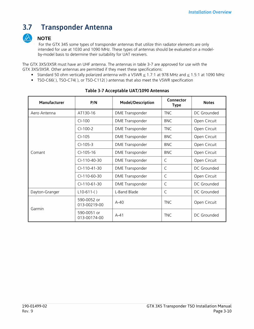
Installation Overview
3.7 Transponder AntennaNOTEFor the GTX 345 some types of transponder antennas that utilize thin radiator elements are only intended for use at 1030 and 1090 MHz. These types of antennas should be evaluated on a model-by-model basis to determine their suitability for UAT receivers.
The GTX 3X5/3X5R must have an UHF antenna. The antennas in table 3-7 are approved for use with the GTX 3X5/3X5R. Other antennas are permitted if they meet these specifications:
• Standard 50 ohm vertically polarized antenna with a VSWR < 1.7:1 at 978 MHz and < 1.5:1 at 1090 MHz• TSO-C66( ), TSO-C74( ), or TSO-C112( ) antennas that also meet the VSWR specification
Table 3-7 Acceptable UAT/1090 Antennas
Manufacturer P/N Model/Description Connector Type Notes
Aero Antenna AT130-16 DME Transponder TNC DC Grounded
Comant
CI-100 DME Transponder BNC Open Circuit
CI-100-2 DME Transponder TNC Open Circuit
CI-105 DME Transponder BNC Open Circuit
CI-105-3 DME Transponder BNC Open Circuit
CI-105-16 DME Transponder BNC Open Circuit
CI-110-40-30 DME Transponder C Open Circuit
CI-110-41-30 DME Transponder C DC Grounded
CI-110-60-30 DME Transponder C Open Circuit
CI-110-61-30 DME Transponder C DC Grounded
Dayton-Granger L10-611-( ) L-Band Blade C DC Grounded
Garmin
590-0052 or013-00219-00
A-40 TNC Open Circuit
590-0051 or013-00174-00
A-41 TNC DC Grounded
190-01499-02 GTX 3X5 Transponder TSO Installation ManualRev. 9 Page 3-10

Installation Overview
3.8 GPS Antenna RequirementsUse an antenna in table 3-8 to get the best performance with the GTX 3X5 with internal GNSS receiver. The antennas in table 3-8 meet specifications in the document Antenna Minimum Performance Specification for Garmin’s GPS/WAAS Receiver System.
Table 3-8 GNSS Receiver Antennas
[1] Same mounting hole pattern as GA 56, except GA 35 has a physically larger footprint.
[2] The GPS antenna connector is a TNC and the VHF connector is BNC.
[3] The GPS antenna connector is a TNC connector, the XM connector is TNC, and the VHF connector is BNC.
Model/Description Connector Type Manufacturer P/N
Garmin Order
Number
GA 35, GPS/WAAS [1] TNCGarmin 013-00235-( ) 013-00235-( )
Aero Antenna AT575-93G( )-TNCF-000-RG-27-NM N/A
GA 36, GPS/WAAS TNCGarmin 013-00244-( ) 013-00244-( )
Aero Antenna AT575-126G( )-TNCF-000-RG-27-NM N/A
GA 37, GPS/WAAS/XM TNCGarmin 013-00245-( ) 013-00245-( )
Aero Antenna AT2300-126G( )-TNCF-000-RG-27-NM N/A
A33W, WAAS Antenna TNCGarmin 013-00261-( ) 013-00261-( )
Aero Antenna AT575-332G( )-TNCF-000-RG-27-NM N/A
GPS/VHF Antenna [2] TNC/BNC Comant CI-2580-200 N/A
GPS/VHF Antenna [2] TNC/BNC Comant CI-2728-200 N/A
GPS/XM/VHF Antenna [3] TNC/TNC/BNC Comant CI-2580-410 N/A
GPS/XM/VHF Antenna [3] TNC/TNC/BNC Comant CI-2728-410 N/A
GPS/WAAS Antenna TNC Comant CI-428-200 N/A
GPS/XM Antenna TNC/TNC Comant CI-428-410 N/A
190-01499-02 GTX 3X5 Transponder TSO Installation ManualRev. 9 Page 3-11
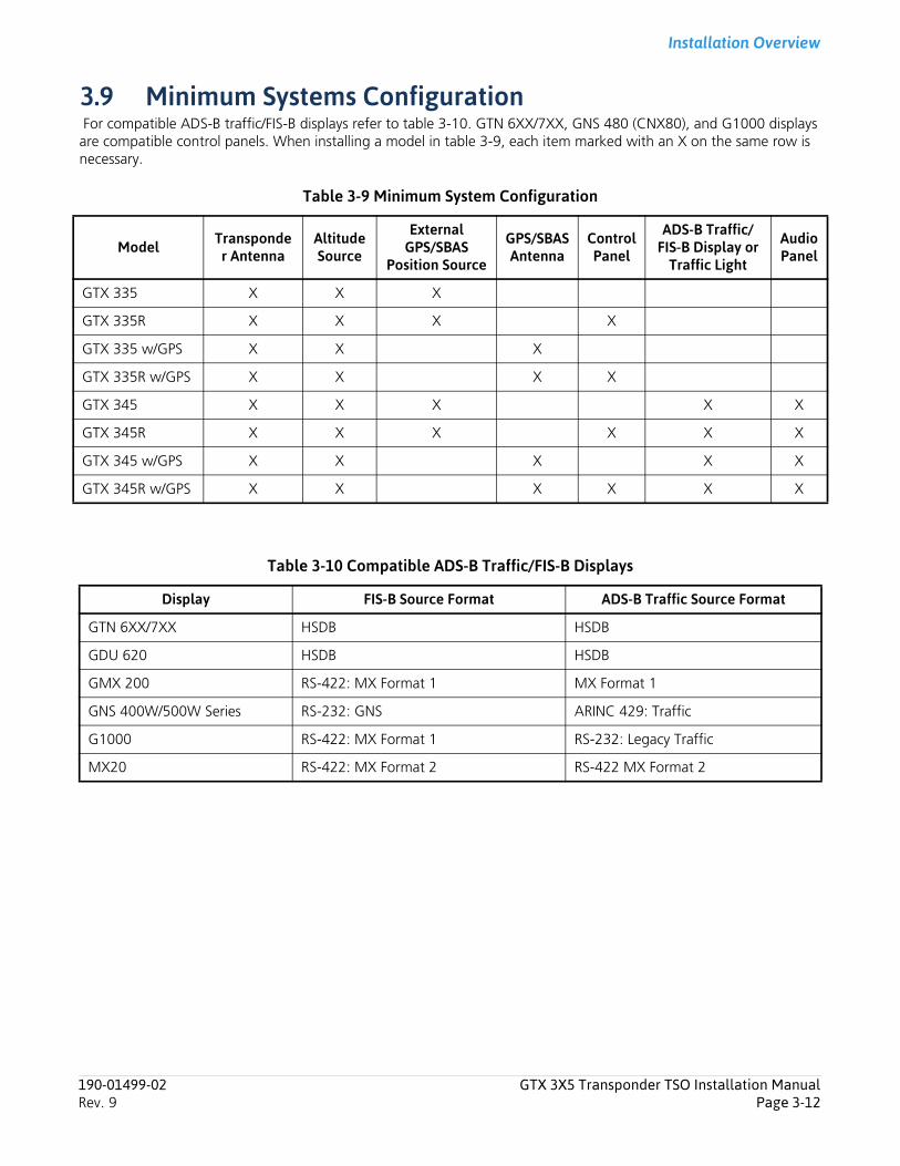
Installation Overview
3.9 Minimum Systems Configuration For compatible ADS-B traffic/FIS-B displays refer to table 3-10. GTN 6XX/7XX, GNS 480 (CNX80), and G1000 displays are compatible control panels. When installing a model in table 3-9, each item marked with an X on the same row is necessary.
Table 3-9 Minimum System Configuration
Table 3-10 Compatible ADS-B Traffic/FIS-B Displays
Model Transponder Antenna
Altitude Source
External GPS/SBAS
Position Source
GPS/SBAS Antenna
Control Panel
ADS-B Traffic/FIS-B Display or
Traffic Light
Audio Panel
GTX 335 X X X
GTX 335R X X X X
GTX 335 w/GPS X X X
GTX 335R w/GPS X X X X
GTX 345 X X X X X
GTX 345R X X X X X X
GTX 345 w/GPS X X X X X
GTX 345R w/GPS X X X X X X
Display FIS-B Source Format ADS-B Traffic Source Format
GTN 6XX/7XX HSDB HSDB
GDU 620 HSDB HSDB
GMX 200 RS-422: MX Format 1 MX Format 1
GNS 400W/500W Series RS-232: GNS ARINC 429: Traffic
G1000 RS-422: MX Format 1 RS-232: Legacy Traffic
MX20 RS-422: MX Format 2 RS-422 MX Format 2
190-01499-02 GTX 3X5 Transponder TSO Installation ManualRev. 9 Page 3-12
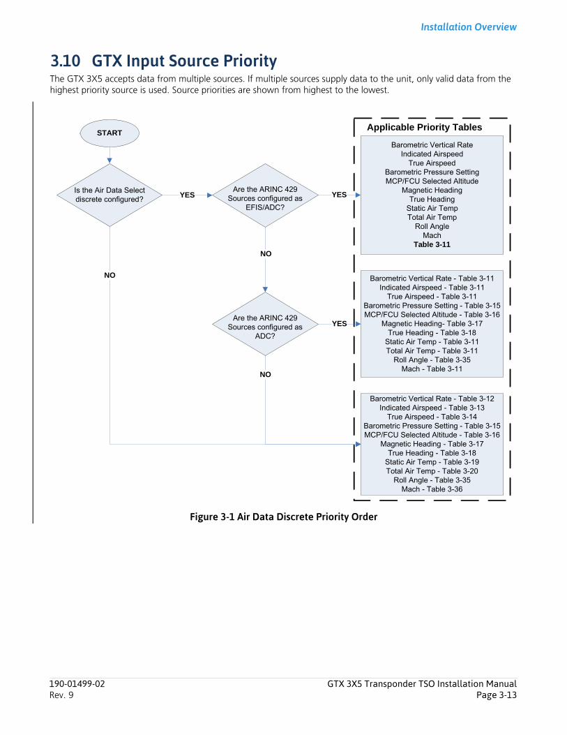
Installation Overview
3.10 GTX Input Source PriorityThe GTX 3X5 accepts data from multiple sources. If multiple sources supply data to the unit, only valid data from the highest priority source is used. Source priorities are shown from highest to the lowest.
Figure 3-1 Air Data Discrete Priority Order
Is the Air Data Select discrete configured?
Barometric Vertical RateIndicated Airspeed
True AirspeedBarometric Pressure SettingMCP/FCU Selected Altitude
Magnetic HeadingTrue Heading
Static Air TempTotal Air Temp
Roll AngleMach
Table 3-11
YES
Barometric Vertical Rate - Table 3-12Indicated Airspeed - Table 3-13
True Airspeed - Table 3-14Barometric Pressure Setting - Table 3-15MCP/FCU Selected Altitude - Table 3-16
Magnetic Heading - Table 3-17True Heading - Table 3-18
Static Air Temp - Table 3-19Total Air Temp - Table 3-20
Roll Angle - Table 3-35Mach - Table 3-36
NO
Applicable Priority TablesSTART
Are the ARINC 429 Sources configured as
EFIS/ADC?
YES
Barometric Vertical Rate - Table 3-11Indicated Airspeed - Table 3-11
True Airspeed - Table 3-11Barometric Pressure Setting - Table 3-15MCP/FCU Selected Altitude - Table 3-16
Magnetic Heading- Table 3-17True Heading - Table 3-18
Static Air Temp - Table 3-11Total Air Temp - Table 3-11
Roll Angle - Table 3-35Mach - Table 3-11
NO
Are the ARINC 429 Sources configured as
ADC?
NO
YES
190-01499-02 GTX 3X5 Transponder TSO Installation ManualRev. 9 Page 3-13
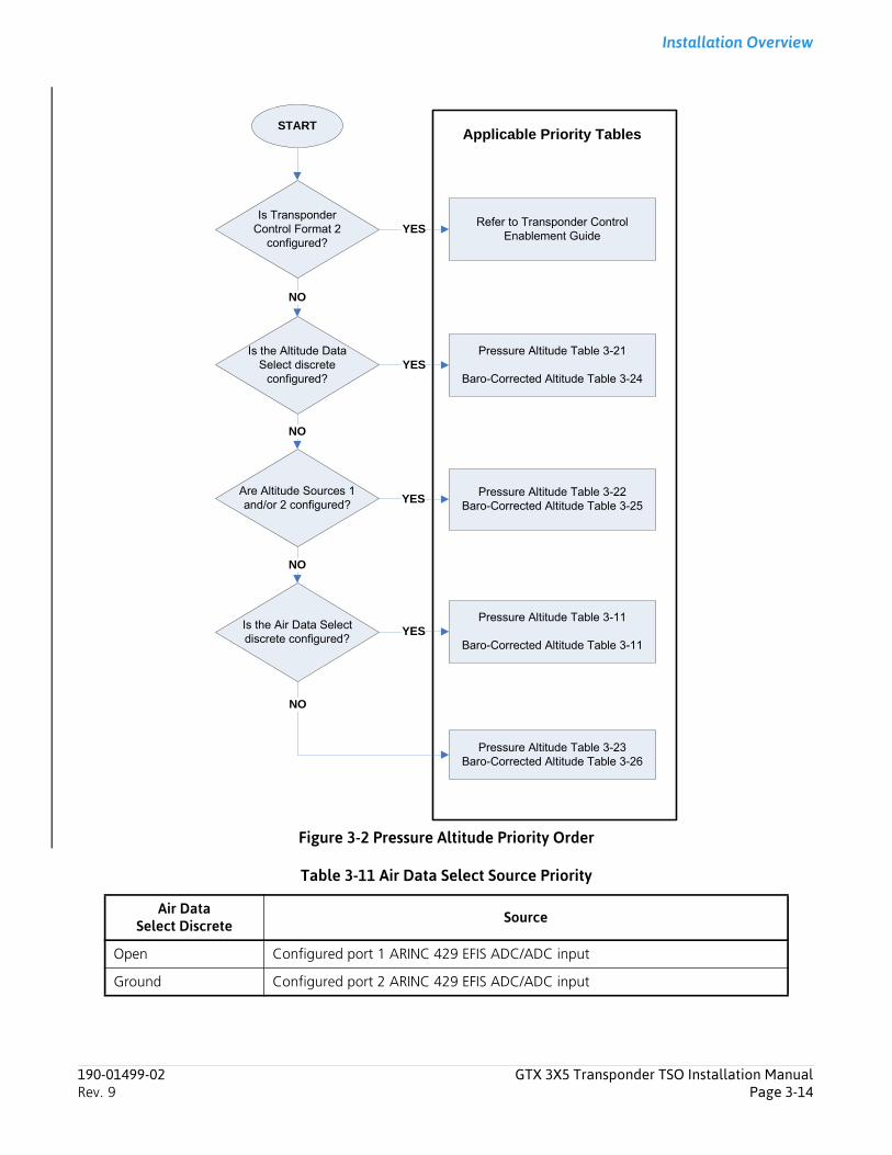
Installation Overview
Figure 3-2 Pressure Altitude Priority Order
Table 3-11 Air Data Select Source Priority
Air Data Select Discrete Source
Open Configured port 1 ARINC 429 EFIS ADC/ADC input
Ground Configured port 2 ARINC 429 EFIS ADC/ADC input
Is the Altitude Data Select discrete
configured?
Pressure Altitude Table 3-21
Baro-Corrected Altitude Table 3-24YES
Is the Air Data Select discrete configured?
Pressure Altitude Table 3-11
Baro-Corrected Altitude Table 3-11YES
NO
NO
Are Altitude Sources 1 and/or 2 configured?
Pressure Altitude Table 3-22Baro-Corrected Altitude Table 3-25
YES
Pressure Altitude Table 3-23Baro-Corrected Altitude Table 3-26
NO
Applicable Priority TablesSTART
Is Transponder Control Format 2
configured?
Refer to Transponder Control Enablement Guide
YES
NO
190-01499-02 GTX 3X5 Transponder TSO Installation ManualRev. 9 Page 3-14
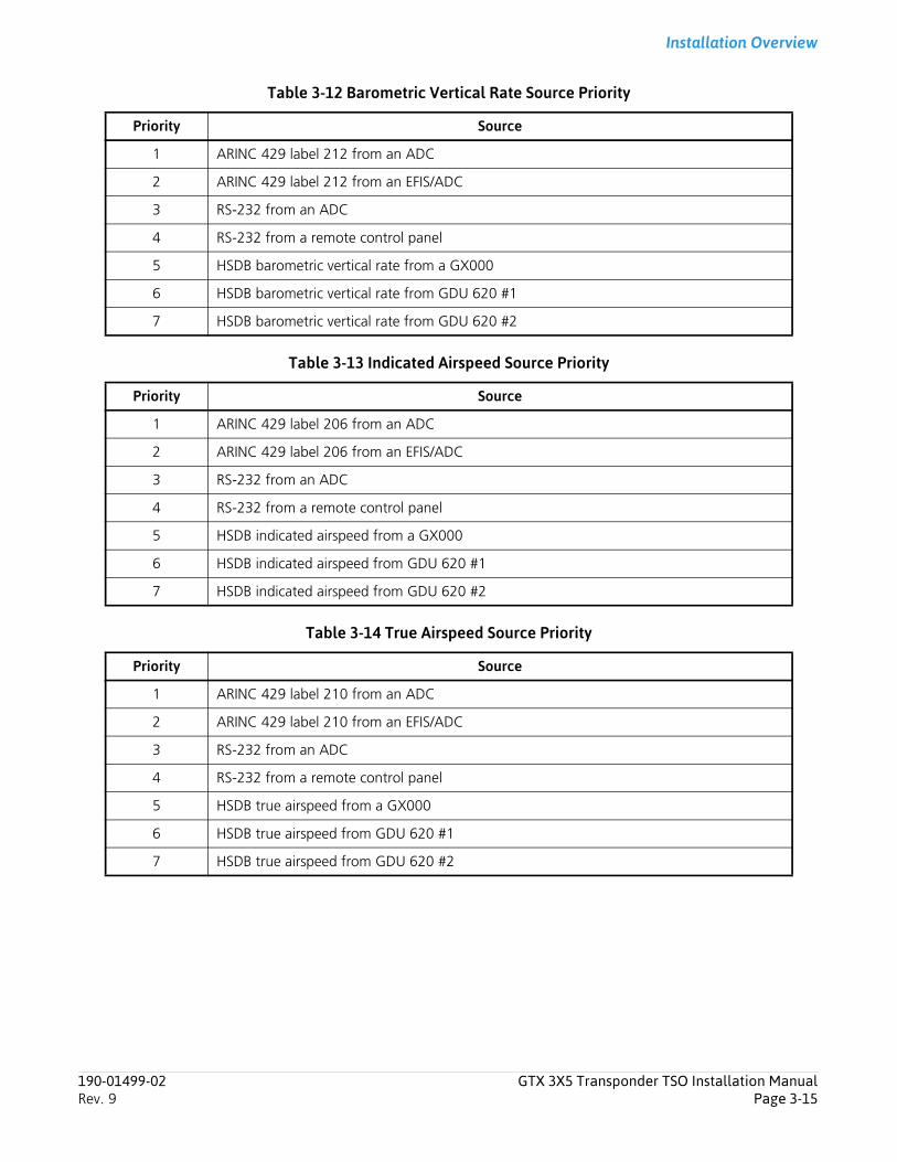
Installation Overview
Table 3-12 Barometric Vertical Rate Source Priority
Table 3-13 Indicated Airspeed Source Priority
Table 3-14 True Airspeed Source Priority
Priority Source
1 ARINC 429 label 212 from an ADC
2 ARINC 429 label 212 from an EFIS/ADC
3 RS-232 from an ADC
4 RS-232 from a remote control panel
5 HSDB barometric vertical rate from a GX000
6 HSDB barometric vertical rate from GDU 620 #1
7 HSDB barometric vertical rate from GDU 620 #2
Priority Source
1 ARINC 429 label 206 from an ADC
2 ARINC 429 label 206 from an EFIS/ADC
3 RS-232 from an ADC
4 RS-232 from a remote control panel
5 HSDB indicated airspeed from a GX000
6 HSDB indicated airspeed from GDU 620 #1
7 HSDB indicated airspeed from GDU 620 #2
Priority Source
1 ARINC 429 label 210 from an ADC
2 ARINC 429 label 210 from an EFIS/ADC
3 RS-232 from an ADC
4 RS-232 from a remote control panel
5 HSDB true airspeed from a GX000
6 HSDB true airspeed from GDU 620 #1
7 HSDB true airspeed from GDU 620 #2
190-01499-02 GTX 3X5 Transponder TSO Installation ManualRev. 9 Page 3-15
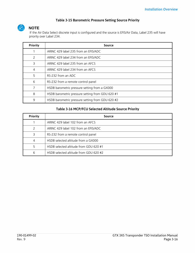
Installation Overview
Table 3-15 Barometric Pressure Setting Source Priority
NOTEIf the Air Data Select discrete input is configured and the source is EFIS/Air Data, Label 235 will have priority over Label 234.
Table 3-16 MCP/FCU Selected Altitude Source Priority
Priority Source
1 ARINC 429 label 235 from an EFIS/ADC
2 ARINC 429 label 234 from an EFIS/ADC
3 ARINC 429 label 235 from an AFCS
4 ARINC 429 label 234 from an AFCS
5 RS-232 from an ADC
6 RS-232 from a remote control panel
7 HSDB barometric pressure setting from a GX000
8 HSDB barometric pressure setting from GDU 620 #1
9 HSDB barometric pressure setting from GDU 620 #2
Priority Source
1 ARINC 429 label 102 from an AFCS
2 ARINC 429 label 102 from an EFIS/ADC
3 RS-232 from a remote control panel
4 HSDB selected altitude from a GX000
5 HSDB selected altitude from GDU 620 #1
6 HSDB selected altitude from GDU 620 #2
190-01499-02 GTX 3X5 Transponder TSO Installation ManualRev. 9 Page 3-16
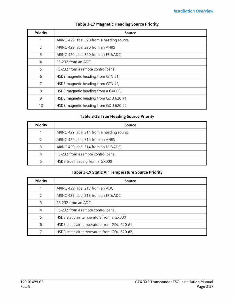
Installation Overview
Table 3-17 Magnetic Heading Source Priority
Table 3-18 True Heading Source Priority
Table 3-19 Static Air Temperature Source Priority
Priority Source
1 ARINC 429 label 320 from a heading source
2 ARINC 429 label 320 from an AHRS
3 ARINC 429 label 320 from an EFIS/ADC
4 RS-232 from an ADC
5 RS-232 from a remote control panel
6 HSDB magnetic heading from GTN #1
7 HSDB magnetic heading from GTN #2
8 HSDB magnetic heading from a GX000
9 HSDB magnetic heading from GDU 620 #1
10 HSDB magnetic heading from GDU 620 #2
Priority Source
1 ARINC 429 label 314 from a heading source
2 ARINC 429 label 314 from an AHRS
3 ARINC 429 label 314 from an EFIS/ADC
4 RS-232 from a remote control panel
5 HSDB true heading from a GX000
Priority Source
1 ARINC 429 label 213 from an ADC
2 ARINC 429 label 213 from an EFIS/ADC
3 RS-232 from an ADC
4 RS-232 from a remote control panel
5 HSDB static air temperature from a GX000
6 HSDB static air temperature from GDU 620 #1
7 HSDB static air temperature from GDU 620 #2
190-01499-02 GTX 3X5 Transponder TSO Installation ManualRev. 9 Page 3-17
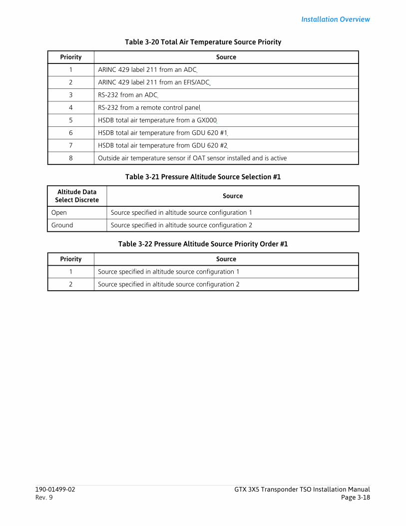
Installation Overview
Table 3-20 Total Air Temperature Source Priority
Table 3-21 Pressure Altitude Source Selection #1
Table 3-22 Pressure Altitude Source Priority Order #1
Priority Source
1 ARINC 429 label 211 from an ADC
2 ARINC 429 label 211 from an EFIS/ADC
3 RS-232 from an ADC
4 RS-232 from a remote control panel
5 HSDB total air temperature from a GX000
6 HSDB total air temperature from GDU 620 #1
7 HSDB total air temperature from GDU 620 #2
8 Outside air temperature sensor if OAT sensor installed and is active
Altitude Data Select Discrete Source
Open Source specified in altitude source configuration 1
Ground Source specified in altitude source configuration 2
Priority Source
1 Source specified in altitude source configuration 1
2 Source specified in altitude source configuration 2
190-01499-02 GTX 3X5 Transponder TSO Installation ManualRev. 9 Page 3-18

Installation Overview
Table 3-23 Pressure Altitude Source Priority Order #12
Table 3-24 Baro-Corrected Altitude Source Selection #1
Table 3-25 Baro-Corrected Altitude Source Priority Order #1
Table 3-26 Baro-Corrected Altitude Source Priority Order #2
Priority Source
1 ARINC 429 label 203 from an ADC
2 ARINC 429 label 203 from an EFIS/ADC
3 RS-232 from an ADC
4 RS-232 from a 25 ft resolution altitude source
5 RS-232 from a remote control panel
6 Optional GAE module
7 HSDB pressure altitude from GTN #1
8 HSDB pressure altitude from GTN #2
9 HSDB pressure altitude from a GX000
10 HSDB pressure altitude from GDU 620 #1
11 HSDB pressure altitude from GDU 620 #2
12 Gray code altitude
13 RS-232 from a 100 ft resolution altitude source
Altitude Data Select Discrete Source
Open Source specified in altitude source configuration 1
Ground Source specified in altitude source configuration 2
Priority Source
1 Source specified in altitude source configuration 1
2 Source specified in altitude source configuration 2
Priority Source
1 ARINC 429 label 204 from an ADC
2 ARINC 429 label 204 from an EFIS/ADC
3 RS-232 from an ADC
190-01499-02 GTX 3X5 Transponder TSO Installation ManualRev. 9 Page 3-19
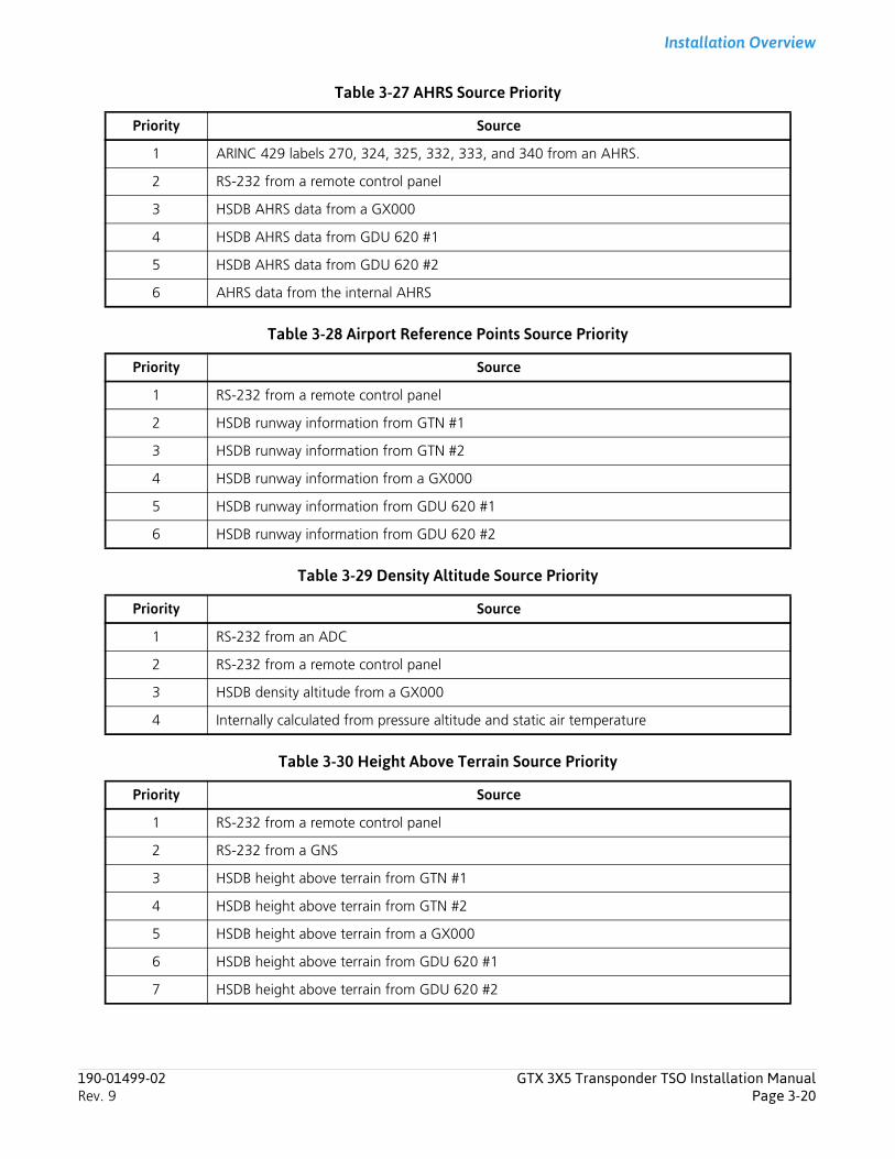
Installation Overview
Table 3-27 AHRS Source Priority
Table 3-28 Airport Reference Points Source Priority
Table 3-29 Density Altitude Source Priority
Table 3-30 Height Above Terrain Source Priority
Priority Source
1 ARINC 429 labels 270, 324, 325, 332, 333, and 340 from an AHRS.
2 RS-232 from a remote control panel
3 HSDB AHRS data from a GX000
4 HSDB AHRS data from GDU 620 #1
5 HSDB AHRS data from GDU 620 #2
6 AHRS data from the internal AHRS
Priority Source
1 RS-232 from a remote control panel
2 HSDB runway information from GTN #1
3 HSDB runway information from GTN #2
4 HSDB runway information from a GX000
5 HSDB runway information from GDU 620 #1
6 HSDB runway information from GDU 620 #2
Priority Source
1 RS-232 from an ADC
2 RS-232 from a remote control panel
3 HSDB density altitude from a GX000
4 Internally calculated from pressure altitude and static air temperature
Priority Source
1 RS-232 from a remote control panel
2 RS-232 from a GNS
3 HSDB height above terrain from GTN #1
4 HSDB height above terrain from GTN #2
5 HSDB height above terrain from a GX000
6 HSDB height above terrain from GDU 620 #1
7 HSDB height above terrain from GDU 620 #2
190-01499-02 GTX 3X5 Transponder TSO Installation ManualRev. 9 Page 3-20

Installation Overview
Table 3-31 Radio Altitude Source Priority
Table 3-32 Selected Course and Joystick Waypoint Source Priority
Table 3-33 FMS Selected Altitude Priority
Table 3-34 Magnetic Variation Source Priority
Priority Source
1 ARINC 429 label 164 from a radar altimeter
2 ARINC 429 label 164 from an EFIS/ADC
3 RS-232 from a remote control panel
4 HSDB radio height from GTN #1
5 HSDB radio height from GTN #2
6 HSDB radio height from a GX000
7 HSDB radio height from GDU 620 #1
8 HSDB radio height from GDU 620 #2
Priority Source
1 ARINC 429 labels 100, 306, and 307 from an EFIS/ADC
Priority Source
1 RS-232 from a remote control panel
2 HSDB FMS vertical navigation data from a GX000
3 HSDB FMS vertical navigation data from GDU 620 #1
4 HSDB FMS vertical navigation data from GDU 620 #2
Priority Source
1 HSDB magnetic variation from a GX000
2 HSDB magnetic variation from GDU 620 #1
3 HSDB magnetic variation from GTN #1
4 HSDB magnetic variation from GTN #2
5 HSDB magnetic variation from GDU 620 #2
6 RS-232 from a GNS
190-01499-02 GTX 3X5 Transponder TSO Installation ManualRev. 9 Page 3-21
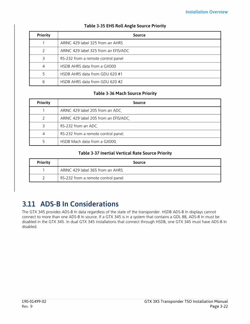
Installation Overview
Table 3-35 EHS Roll Angle Source Priority
Table 3-36 Mach Source Priority
Table 3-37 Inertial Vertical Rate Source Priority
3.11 ADS-B In ConsiderationsThe GTX 345 provides ADS-B In data regardless of the state of the transponder. HSDB ADS-B In displays cannot connect to more than one ADS-B In source. If a GTX 345 is in a system that contains a GDL 88, ADS-B In must be disabled in the GTX 345. In dual GTX 345 installations that connect through HSDB, one GTX 345 must have ADS-B In disabled.
Priority Source
1 ARINC 429 label 325 from an AHRS
2 ARINC 429 label 325 from an EFIS/ADC
3 RS-232 from a remote control panel
4 HSDB AHRS data from a GX000
5 HSDB AHRS data from GDU 620 #1
6 HSDB AHRS data from GDU 620 #2
Priority Source
1 ARINC 429 label 205 from an ADC
2 ARINC 429 label 205 from an EFIS/ADC
3 RS-232 from an ADC
4 RS-232 from a remote control panel
5 HSDB Mach data from a GX000
Priority Source
1 ARINC 429 label 365 from an AHRS
2 RS-232 from a remote control panel
190-01499-02 GTX 3X5 Transponder TSO Installation ManualRev. 9 Page 3-22
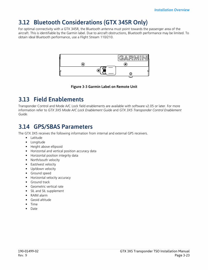
Installation Overview
3.12 Bluetooth Considerations (GTX 345R Only)For optimal connectivity with a GTX 345R, the Bluetooth antenna must point towards the passenger area of the aircraft. This is identifiable by the Garmin label. Due to aircraft obstructions, Bluetooth performance may be limited. To obtain ideal Bluetooth performance, use a Flight Stream 110/210.
Figure 3-3 Garmin Label on Remote Unit
3.13 Field EnablementsTransponder Control and Mode A/C Lock field enablements are available with software v2.05 or later. For more information refer to GTX 3X5 Mode A/C Lock Enablement Guide and GTX 3X5 Transponder Control Enablement Guide.
3.14 GPS/SBAS ParametersThe GTX 3X5 receives the following information from internal and external GPS receivers.
• Latitude• Longitude• Height above ellipsoid• Horizontal and vertical position accuracy data• Horizontal position integrity data• North/south velocity• East/west velocity• Up/down velocity• Ground speed• Horizontal velocity accuracy• Ground track• Geometric vertical rate• SIL and SIL supplement• RAIM alarm• Geoid altitude• Time• Date
190-01499-02 GTX 3X5 Transponder TSO Installation ManualRev. 9 Page 3-23
Installation Overview
3.15 Antenna ConsiderationsMounting location considerations for the antenna(s) are provided in this section. The recommended antenna locations are shown in figure 3-4.
3.15.1 Transponder AntennaGround planes must be considered for installations on composite aircraft. Conductive wire mesh, radials, or thin aluminum sheets embedded in the composite material supply the ground plane to maximize the antenna pattern (gain). This can improve transponder performance.
The antenna mounting must use the aircraft manufacturer’s type certificated antenna location and style. The antenna must be installed in accordance with manufacturer instructions and/or AC 43.12-2A Chapter 3.
Transponder antenna considerations help the installer to select the best location for the antenna. The antenna should:
1. Be attached away from major protrusions, such as engines, nacelles, propellers, and antenna masts.
2. Be as far as practical from landing gear doors, access doors, or other openings that could affect its radiation pattern.
3. Be vertically attached on the bottom of the aircraft.
4. Not be attached within three feet of the ADF sense antenna or any other communication antenna.
5. Not be attached within six feet of a DME antenna.
6. Be attached a minimum of three feet from the GTX 3X5 to prevent RF interference.
190-01499-02 GTX 3X5 Transponder TSO Installation ManualRev. 9 Page 3-24
Installation Overview
3.15.2 GPS Antenna
NOTEWhen attaching a combination antenna, the recommended distance of two feet or more is not applicable to the distance between the antenna elements of the combination antenna (ex. GPS and COM, GPS and XM) provided the combination antenna is TSO authorized and has been tested to meet Garmin’s minimum performance standards. For approved antennas refer to table 1-12.
NOTEIf twelve inch spacing is not practical, the maximum center-to-center spacing must be used, but never less than nine inches. Spacing less than nine inches results in unacceptable antenna pattern degradation.
The installation guidelines meet the intent of AC 20-138A section 16. The greater the deviation from these guidelines, the greater the chance of decreased signal quality and availability. It is possible that all of the installation guidelines cannot be met. These guidelines are listed in order of importance to get the best performance. The installer should use best judgment to balance the installation guidelines.
The GPS antenna should:
1. Be installed as near to level as possible with respect to the normal cruise flight attitude of the aircraft.
2. Be installed in a location to minimize the effects of airframe shadowing during typical maneuvers.
3. Be installed a minimum of two feet from any VHF COM antenna or any other antenna which may emit harmonic interference at the L1 frequency of 1575.42 MHz.
4. Be installed a minimum of two feet from any antennas emitting more than 25 watts.
5. Be installed a minimum of nine inches (center to center) from other antennas, including passive antennas such as another GPS or XM antenna.
6. Be installed a minimum of three inches from the windscreen.
7. Have a twelve inch center to center spacing between GPS antennas.
An aircraft EMC check can find the source of GPS degradation in the presence of interference signals. If an EMC check shows unacceptable interference, either insert a GPS notch filter in line with the offending VHF COM or the (re-radiating) ELT transmitter, or select a different GPS antenna location.
190-01499-02 GTX 3X5 Transponder TSO Installation ManualRev. 9 Page 3-25
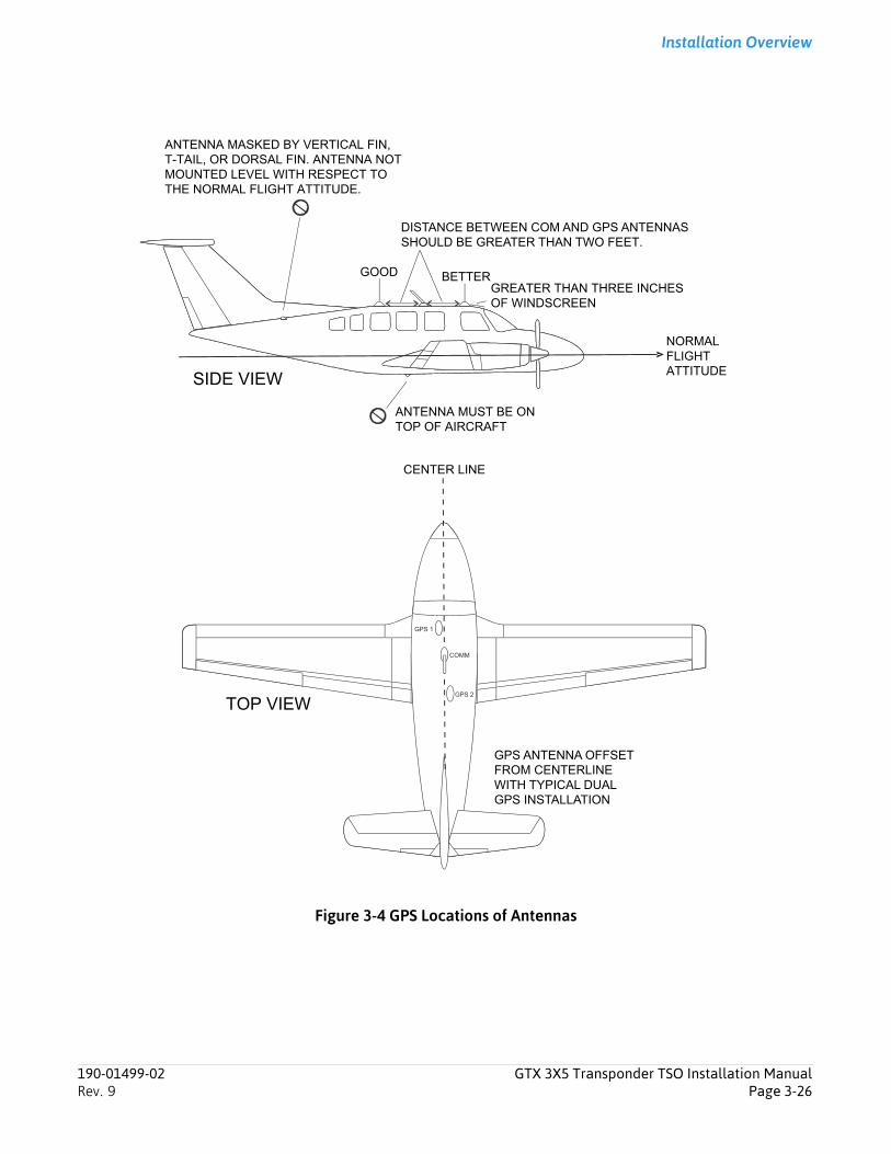
Installation Overview
Figure 3-4 GPS Locations of Antennas
DISTANCE BETWEEN COM AND GPS ANTENNAS
ANTENNA MASKED BY VERTICAL FIN,T-TAIL, OR DORSAL FIN. ANTENNA NOTMOUNTED LEVEL WITH RESPECT TOTHE NORMAL FLIGHT ATTITUDE.
GOOD BETTERGREATER THAN THREE INCHES OF WINDSCREEN
NORMALFLIGHT ATTITUDE
ANTENNA MUST BE ONTOP OF AIRCRAFT
CENTER LINE
SHOULD BE GREATER THAN TWO FEET.
SIDE VIEW
TOP VIEW
GPS ANTENNA OFFSETFROM CENTERLINEWITH TYPICAL DUAL GPS INSTALLATION
190-01499-02 GTX 3X5 Transponder TSO Installation ManualRev. 9 Page 3-26
Installation Overview
3.16 Electrical BondingMake sure the transponder and GPS antennas are electrically bonded to the aircraft.
3.17 Cabling and Wiring Use AC 43.13-1B chapter 11, sections 8 through 13 to install wiring. The considerations are:
1. It should not be possible for the cable harness to be exposed to wire chafing.
2. The cable harness should not be located near flight control cables, high capacity electrical lines (e.g., DC electric motor cables), or fuel lines.
3. Do not put cables near high energy sources (e.g., DC motors, high heat sources).
4. Wiring that must be shielded must be done as shown in appendix D.
5. Shield pigtail lengths must be less than 3.0 inches.
3.18 Electrical Bonding ConsiderationsBond electrical equipment, supporting brackets, and racks to the aircraft’s main structure. When surface preparation is necessary to get an electrical bond refer to SAE ARP 1870 section 5. To measure the resistance of the bond between the equipment and the adjacent aircraft structure use a calibrated milliohm meter. The bond must have a DC resistance no more than 2.5 milliohms.
3.19 Cooling Requirements and ConsiderationsThere are no cooling requirements or considerations for the GTX 3X5. The chassis has provisions for a fan, however, one is not necessary or provided.
190-01499-02 GTX 3X5 Transponder TSO Installation ManualRev. 9 Page 3-27

Installation Procedure
4 Installation Procedure4.1 Wire Harness Installation................................................................................................................................ 4-14.2 Backshell Assembly Parts................................................................................................................................ 4-24.3 Shielded Cable Preparation ............................................................................................................................ 4-34.4 Connector and Backshell Assembly ................................................................................................................ 4-54.5 Configuration Module Installation.................................................................................................................. 4-84.6 Coax Cable Installation ................................................................................................................................ 4-104.7 Equipment Rack Installation ......................................................................................................................... 4-10
4.7.1 Panel Mount Units................................................................................................................................. 4-104.7.2 Standard Remote Mount Units .............................................................................................................. 4-114.7.3 Vertical Remote Mount Units................................................................................................................. 4-114.7.4 GX000 Integrated Flight Decks .............................................................................................................. 4-114.7.5 GAE Installation........................................................................................................................................ 4-11
4.8 Panel and Standard Remote Mount Unit Installation and Removal................................................................ 4-134.9 Vertical Remote Mount Unit Installation and Removal .................................................................................. 4-14
4.1 Wire Harness InstallationAll electrical connections, except for the antenna(s) and shield grounds, are made through the D-sub connectors on the rear of the unit. The shield grounds terminate to the connector backshells.
For additional information:• For rear connector pinout and descriptions of interface connections refer to section 5• For interconnect diagrams, refer to appendix D • For special tools, refer to section 3.15
Give sufficient space for installation of cables and connectors. The installer supplies and assembles all cables. Cable lengths are dependent upon the installation.
To install pins into connectors and build a wire harness:
1. Remove 0.17 inches of insulation from wires going to the connectors.
2. Put the wire into the pin and crimp with one of the recommended (or equivalent) crimping tools.
3. Put the pin into the connector housing location as specified by the interconnect drawings in appendix D.
4. Gently pull on the wire to make sure the pin is properly engaged into the connector.
5. Route and attach the cable run from the GTX 3X5 to the other units. Refer to section 3.17.
190-01499-02 GTX 3X5 Transponder TSO Installation ManualRev. 9 Page 4-1
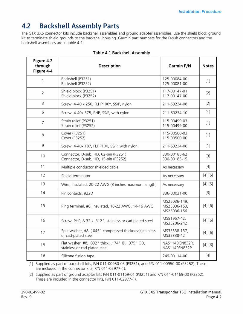
Installation Procedure
4.2 Backshell Assembly PartsThe GTX 3X5 connector kits include backshell assemblies and ground adapter assemblies. Use the shield block ground kit to terminate shield grounds to the backshell housing. Garmin part numbers for the D-sub connectors and the backshell assemblies are in table 4-1.
Table 4-1 Backshell Assembly
[1] Supplied as part of backshell kits, P/N 011-00950-03 (P3251), and P/N 011-00950-00 (P3252). These are included in the connector kits, P/N 011-02977-( ).
[2] Supplied as part of ground adapter kits P/N 011-01169-01 (P3251) and P/N 011-01169-00 (P3252). These are included in the connector kits, P/N 011-02977-( ).
Figure 4-2 through
Figure 4-4Description Garmin P/N Notes
1 Backshell (P3251)Backshell (P3252)
125-00084-00125-00081-00
[1]
2 Shield block (P3251) Shield block (P3252)
117-00147-01117-00147-00
[2]
3 Screw, 4-40 x.250, FLHP100°, SS/P, nylon 211-63234-08 [2]
6 Screw, 4-40x.375, PHP, SS/P, with nylon 211-60234-10 [1]
7 Strain relief (P3251)Strain relief (P3252)
115-00499-03115-00499-00
[1]
8 Cover (P3251)Cover (P3252)
115-00500-03115-00500-00
[1]
9 Screw, 4-40x.187, FLHP100, SS/P, with nylon 211-63234-06 [1]
10 Connector, D-sub, HD, 62-pin (P3251)Connector, D-sub, HD, 15-pin (P3252)
330-00185-62330-00185-15
[3]
11 Multiple conductor shielded cable As necessary [4]
12 Shield terminator As necessary [4] [5]
13 Wire, insulated, 20-22 AWG (3 inches maximum length) As necessary [4] [5]
14 Pin contacts, #22D 336-00021-00 [3]
15 Ring terminal, #8, insulated, 18-22 AWG, 14-16 AWGMS25036-149,MS25036-153,MS25036-156
[4] [6]
16 Screw, PHP, 8-32 x .312", stainless or cad plated steelMS51957-42,MS35206-242
[4] [6]
17 Split washer, #8, (.045" compressed thickness) stainless or cad-plated steel
MS35338-137,MS35338-42
[4] [6]
18 Flat washer, #8, .032" thick, .174" ID, .375" OD, stainless or cad plated steel
NAS1149CN832R,NAS1149FN832P
[4] [6]
19 Silicone fusion tape 249-00114-00 [4]
190-01499-02 GTX 3X5 Transponder TSO Installation ManualRev. 9 Page 4-2
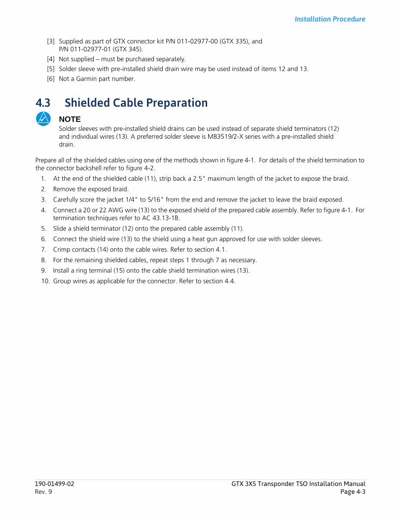
Installation Procedure
[3] Supplied as part of GTX connector kit P/N 011-02977-00 (GTX 335), and P/N 011-02977-01 (GTX 345).
[4] Not supplied – must be purchased separately.
[5] Solder sleeve with pre-installed shield drain wire may be used instead of items 12 and 13.
[6] Not a Garmin part number.
4.3 Shielded Cable PreparationNOTESolder sleeves with pre-installed shield drains can be used instead of separate shield terminators (12) and individual wires (13). A preferred solder sleeve is M83519/2-X series with a pre-installed shield drain.
Prepare all of the shielded cables using one of the methods shown in figure 4-1. For details of the shield termination to the connector backshell refer to figure 4-2.
1. At the end of the shielded cable (11), strip back a 2.5" maximum length of the jacket to expose the braid.
2. Remove the exposed braid.
3. Carefully score the jacket 1/4" to 5/16" from the end and remove the jacket to leave the braid exposed.
4. Connect a 20 or 22 AWG wire (13) to the exposed shield of the prepared cable assembly. Refer to figure 4-1. For termination techniques refer to AC 43.13-1B.
5. Slide a shield terminator (12) onto the prepared cable assembly (11).
6. Connect the shield wire (13) to the shield using a heat gun approved for use with solder sleeves.
7. Crimp contacts (14) onto the cable wires. Refer to section 4.1.
8. For the remaining shielded cables, repeat steps 1 through 7 as necessary.
9. Install a ring terminal (15) onto the cable shield termination wires (13).
10. Group wires as applicable for the connector. Refer to section 4.4.
190-01499-02 GTX 3X5 Transponder TSO Installation ManualRev. 9 Page 4-3
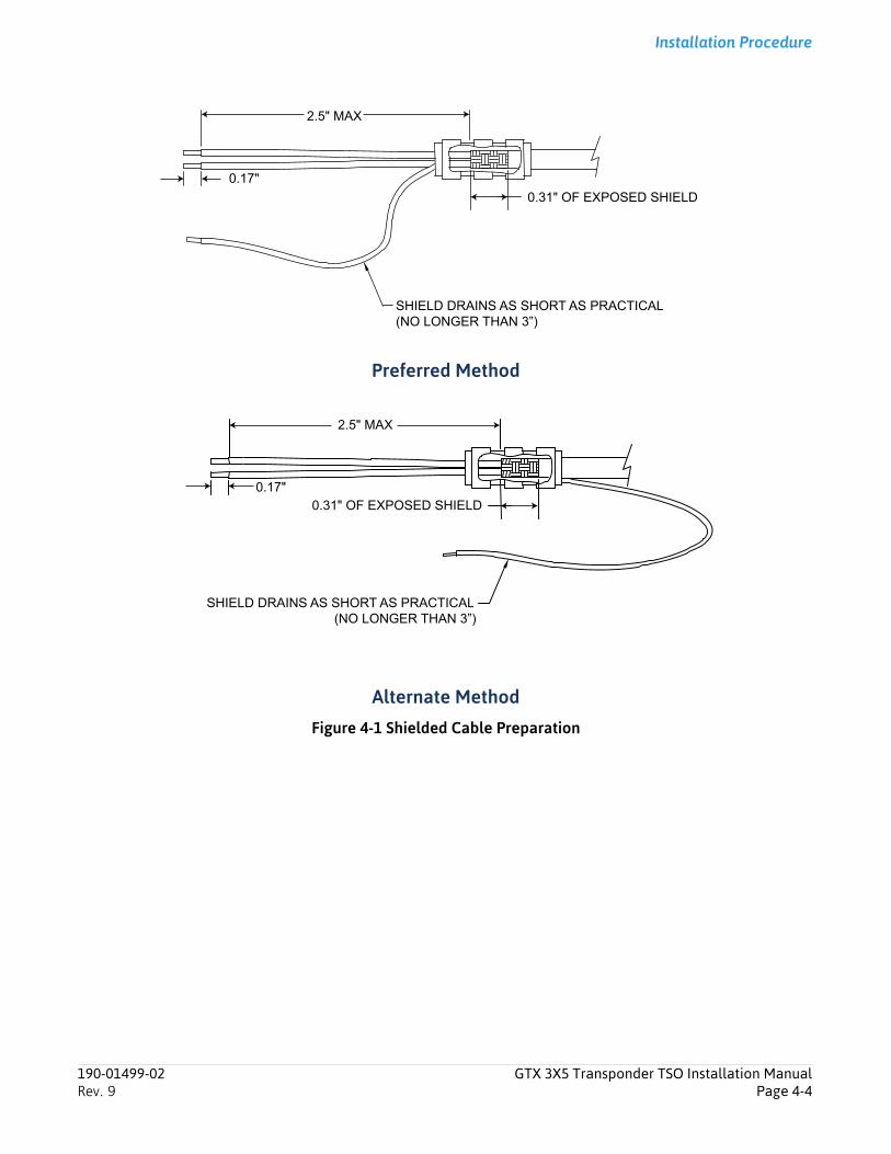
Installation Procedure
Preferred Method
Alternate Method
Figure 4-1 Shielded Cable Preparation
SHIELD DRAINS AS SHORT AS PRACTICAL(NO LONGER THAN 3”)
0.31" OF EXPOSED SHIELD
2.5" MAX
0.17"
SHIELD DRAINS AS SHORT AS PRACTICAL(NO LONGER THAN 3”)
0.31" OF EXPOSED SHIELD
2.5" MAX
0.17"
190-01499-02 GTX 3X5 Transponder TSO Installation ManualRev. 9 Page 4-4

Installation Procedure
4.4 Connector and Backshell AssemblyCAUTIONDO NOT PLACE THE CONCAVE SIDE OF THE STRAIN RELIEF CLAMP (9) ACROSS THE CABLE BUNDLE. THE CABLE BUNDLE CAN BE DAMAGED.
NOTEThe configuration module and GAE use the same connector pin locations and cannot be used at the same time.
NOTEEach tapped hole on the backshell (1) will only take two ring terminals (15). It is recommended to terminate a maximum of two wires (13) per ring terminal. This necessitates the use of a ring terminal, #8, insulated, 14-16 AWG (MS25036-153). If only a single wire is left or if only a single wire is necessary for this connector, a ring terminal, #8, insulated, 18-22 AWG (MS25036-149) can be used. If more wires exist for the connector than two per ring terminal, it is permitted to terminate three wires per ring terminal.
For this procedure refer to figure 4-2 and figure 4-3.
1. Insert flathead screws (3) through holes on the shield block (2).
2. Attach to the backshell (1).
3. Insert the crimped wire harness contacts (14) in the D-sub connector (10). For the chosen contact location. refer to appendix D.
4. Install the configuration module or GAE wires into the connector if a configuration module or GAE is used. Refer to section 4.5.
5. Group wires as applicable for the connector.
6. Wrap the cable bundle with silicone fusion tape (19) so the backshell strain relief and cast housing touches the cable bundle.
7. Place the backshell around the connector and wire harness so it rests against the front of the backshell.
8. Place the smooth side of the backshell strain relief clamp (7) across the cable bundle.
9. Attach with three 4-40 x 0.375" pan head screws (6).
10. Attach configuration module. Refer to section 4.5 and figure 4-4.
11. Attach the cover (8) to the backshell using two screws (9).
12. On the pan head screw(16) place in order:
a. Split washer (17)
b. Flat washer (18)
c. First ring terminal (15)
d. If necessary, second ring terminal
13. Insert the assembled pan head screw (16) into the tapped holes on the shield block (2).
190-01499-02 GTX 3X5 Transponder TSO Installation ManualRev. 9 Page 4-5
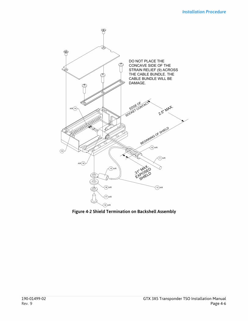
Installation Procedure
Figure 4-2 Shield Termination on Backshell Assembly
.
190-01499-02 GTX 3X5 Transponder TSO Installation ManualRev. 9 Page 4-6
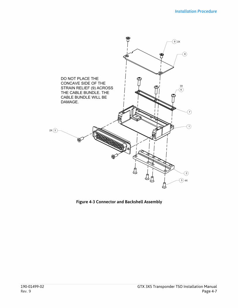
Installation Procedure
Figure 4-3 Connector and Backshell Assembly
190-01499-02 GTX 3X5 Transponder TSO Installation ManualRev. 9 Page 4-7
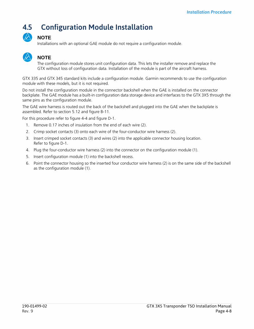
Installation Procedure
4.5 Configuration Module InstallationNOTEInstallations with an optional GAE module do not require a configuration module.
NOTEThe configuration module stores unit configuration data. This lets the installer remove and replace the GTX without loss of configuration data. Installation of the module is part of the aircraft harness.
GTX 335 and GTX 345 standard kits include a configuration module. Garmin recommends to use the configuration module with these models, but it is not required.
Do not install the configuration module in the connector backshell when the GAE is installed on the connector backplate. The GAE module has a built-in configuration data storage device and interfaces to the GTX 3X5 through the same pins as the configuration module.
The GAE wire harness is routed out the back of the backshell and plugged into the GAE when the backplate is assembled. Refer to section 5.12 and figure B-11.
For this procedure refer to figure 4-4 and figure D-1.
1. Remove 0.17 inches of insulation from the end of each wire (2).
2. Crimp socket contacts (3) onto each wire of the four-conductor wire harness (2).
3. Insert crimped socket contacts (3) and wires (2) into the applicable connector housing location. Refer to figure D-1.
4. Plug the four-conductor wire harness (2) into the connector on the configuration module (1).
5. Insert configuration module (1) into the backshell recess.
6. Point the connector housing so the inserted four conductor wire harness (2) is on the same side of the backshell as the configuration module (1).
190-01499-02 GTX 3X5 Transponder TSO Installation ManualRev. 9 Page 4-8
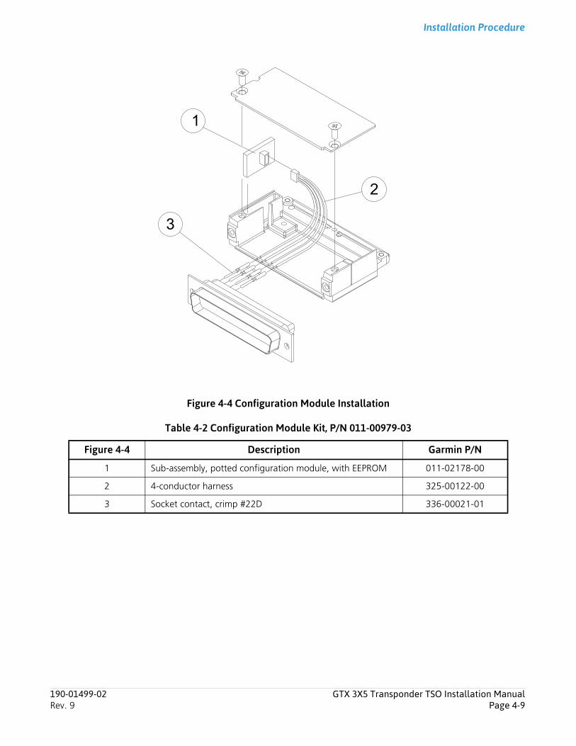
Installation Procedure
Figure 4-4 Configuration Module Installation
Table 4-2 Configuration Module Kit, P/N 011-00979-03
Figure 4-4 Description Garmin P/N
1 Sub-assembly, potted configuration module, with EEPROM 011-02178-00
2 4-conductor harness 325-00122-00
3 Socket contact, crimp #22D 336-00021-01
1
2
3
190-01499-02 GTX 3X5 Transponder TSO Installation ManualRev. 9 Page 4-9
Installation Procedure
4.6 Coax Cable Installation
NOTEMake sure the length is set for the necessary cable loss. Some antennas have minimum cable loss specifications, that may need a cable longer than the physical run in the aircraft.
To install coaxial cables:
1. Route the cable to the radio rack location keeping in mind the recommendations of section 3.17.
2. Attach the cable in accordance with AC 43.13-1B chapter 11, section 11.
3. Trim the cable to the applicable length.
4. Install the connectors to the cable per the manufacturer’s instructions.
4.7 Equipment Rack Installation
4.7.1 Panel Mount Units
CAUTIONEXERCISE CAUTION WHEN INSTALLING THE RACK IN THE INSTRUMENT PANEL. DEFORMATION OF THE RACK WILL MAKE IT DIFFICULT TO INSTALL AND REMOVE THE GTX 3X5.
NOTEIf the front lip of the mounting rack is behind the surface of the aircraft panel, the GTX 3X5 connectors may not fully engage. For more information refer to appendix B.
NOTEMake sure no screw heads or other obstructions prevent the unit from fully engaging in the rack. For drawing dimensions necessary to prepare the cutouts for the GTX 3X5 unit, refer to figure B-9. For drilling the mounting holes, the GTX 3X5 mounting rack may be used as a template.
NOTEStep 3 can be done before or after the wire harness is installed in the aircraft.
1. Install the rack in a rectangular hole (or gap between units) in the instrument panel, typically in the radio stack. The lower front lip of the rack should be flush with, or extend slightly beyond, the finished aircraft panel.
2. Use six #6-32 flat head screws and self-locking nuts to install the rack in the aircraft panel. The screws are inserted from the inside through holes in the sides of the rack.
3. Use provided screws to attach the connector(s) to the backplate.
4. Use two #4-40 flat head screws to attach the GAE to the backplate, if used. Refer to figure B-11.
5. Align the backplate so the backplate screw heads pass through the keyed holes in the back of the rack.
6. Connect the wire harness to the GAE, if used. Refer to figure B-9.
7. Slide the backplate to the left (viewing from the front of the unit) until an audible click is heard.
8. Attach the backplate by tightening the four #4-40 screws.
190-01499-02 GTX 3X5 Transponder TSO Installation ManualRev. 9 Page 4-10
Installation Procedure
4.7.2 Standard Remote Mount UnitsThe GTX 3X5 standard remote mount racks can be mounted in any orientation as long as all six mounting screws are attached to a mounting bracket. Design the mounting bracket(s) for the GTX 3X5 unit with the dimension shown in figure B-4.
Attach the connectors and optional GAE, if used, to the connector backplate the same way as panel mount units. Refer to section 4.7.1.
4.7.3 Vertical Remote Mount UnitsThe GTX 3X5 vertical remote mount base is installed in the vertical orientation with six #10-32 100° flat-head screws and locking nuts. For mounting hole spacing dimensions refer to figure B-6. To mark or drill the mounting holes, the base may be used as a template.
To install the vertical mount shoe:
1. Point the wedge-shaped end of the vertical remote mount shoe to the back of the unit.
2. Attach the vertical remote mount shoe to the unit with the four screws provided.
3. Torque screws to 15-16 in-lbs.
4. Attach the connectors and optional GAE, if used, to the connector backplate the same way as panel mount units. Refer to section 4.7.1.
4.7.4 GX000 Integrated Flight DecksThe GTX 3X5 G1000 rack is mounted to the main system rack with the nutplate kit listed in section 3.4.2. At least eight screws are required to secure the rack as shown in figure B-7. Refer to G1000 System Installation Manual. Attach the connectors and optional GAE, if used, to the connector backplate the same way as panel mount units. Refer to section 4.7.1.
4.7.5 GAE Installation1. Crimp pin contacts onto each wire of the four-conductor wire harness. Strip 0.17" of insulation from each wire
prior to crimping.
2. Insert newly crimped pin contacts and wires into the correct locations in the connector housing.
3. Mount the GAE to the backplate using two countersunk screws as shown in figure 4-5.
4. Torque screws to 8 in-lbs.
5. Plug the four-conductor wire harness into the connector on the GAE. Refer to figure D-1.
190-01499-02 GTX 3X5 Transponder TSO Installation ManualRev. 9 Page 4-11
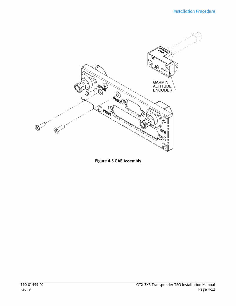
Installation Procedure
Figure 4-5 GAE Assembly
GARMINALTITUDEENCODER
190-01499-02 GTX 3X5 Transponder TSO Installation ManualRev. 9 Page 4-12
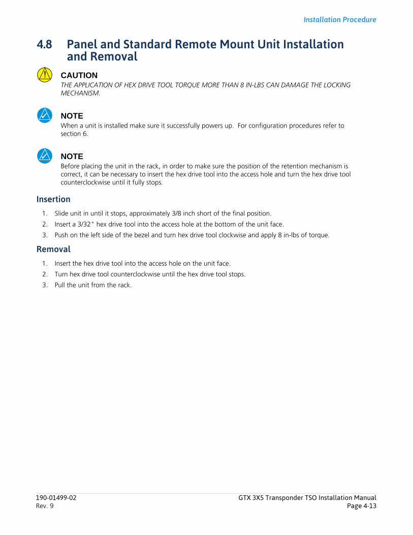
Installation Procedure
4.8 Panel and Standard Remote Mount Unit Installation and Removal
CAUTIONTHE APPLICATION OF HEX DRIVE TOOL TORQUE MORE THAN 8 IN-LBS CAN DAMAGE THE LOCKING MECHANISM.
NOTEWhen a unit is installed make sure it successfully powers up. For configuration procedures refer to section 6.
NOTEBefore placing the unit in the rack, in order to make sure the position of the retention mechanism is correct, it can be necessary to insert the hex drive tool into the access hole and turn the hex drive tool counterclockwise until it fully stops.
Insertion1. Slide unit in until it stops, approximately 3/8 inch short of the final position.
2. Insert a 3/32" hex drive tool into the access hole at the bottom of the unit face.
3. Push on the left side of the bezel and turn hex drive tool clockwise and apply 8 in-lbs of torque.
Removal1. Insert the hex drive tool into the access hole on the unit face.
2. Turn hex drive tool counterclockwise until the hex drive tool stops.
3. Pull the unit from the rack.
190-01499-02 GTX 3X5 Transponder TSO Installation ManualRev. 9 Page 4-13
Installation Procedure
4.9 Vertical Remote Mount Unit Installation and RemovalNOTEWhen a unit is installed make sure it successfully powers up. For configuration procedures refer to section 6.
NOTEThe connector backplate can be attached/detached before or after the installation/removal of the GTX 3X5 onto the base. Refer to figure B-5.
Insertion1. Insert the toe of the GTX 3X5 shoe into the base at an angle.
2. Make sure the unit is fully engaged and in line with the base.
3. Rotate the GTX 3X5 down flat onto the base.
4. Rotate the base locking mechanism up and place the cup over the shoe.
5. Rotate the knob clockwise until tight.
6. Directly attach the connector backplate to the GTX 3X5 with two screws using a 3/32" hex tool.
Removal1. On the base, pull the knob back.
2. Rotate knob counter-clockwise.
3. Remove the cup off of the shoe.
4. Lift the end of the GTX 3X5 from the base and remove the unit.
5. Detach the connector backplate from the GTX 3X5 with a 3/32" hex tool.
190-01499-02 GTX 3X5 Transponder TSO Installation ManualRev. 9 Page 4-14
Connector Pinout Information
5 Connector Pinout Information5.1 Main Board Connector - J3251 ...................................................................................................................... 5-25.2 ADS-B Board Connector - J3252 (GTX 345 Only) ........................................................................................... 5-55.3 Power............................................................................................................................................................ 5-6
5.3.1 Power Configuration and Control Inputs ................................................................................................. 5-65.4 Lighting Bus................................................................................................................................................... 5-75.5 Altitude Inputs............................................................................................................................................... 5-7
5.5.1 Pressure Sensor Module .......................................................................................................................... 5-75.5.2 Gray Code Altitude Input ........................................................................................................................ 5-8
5.6 Discrete I/O.................................................................................................................................................... 5-85.7 Serial Data Interfaces ..................................................................................................................................... 5-9
5.7.1 RS-232.................................................................................................................................................... 5-95.7.2 ARINC 429............................................................................................................................................ 5-105.7.3 HSDB .................................................................................................................................................... 5-105.7.4 RS-422.................................................................................................................................................. 5-10
5.8 Suppression Bus........................................................................................................................................... 5-115.9 OAT Input.................................................................................................................................................... 5-115.10 Audio Output .............................................................................................................................................. 5-115.11 Time Mark ................................................................................................................................................... 5-115.12 Configuration Module ................................................................................................................................. 5-125.13 USB Interface............................................................................................................................................... 5-12
190-01499-02 GTX 3X5 Transponder TSO Installation ManualRev. 9 Page 5-1
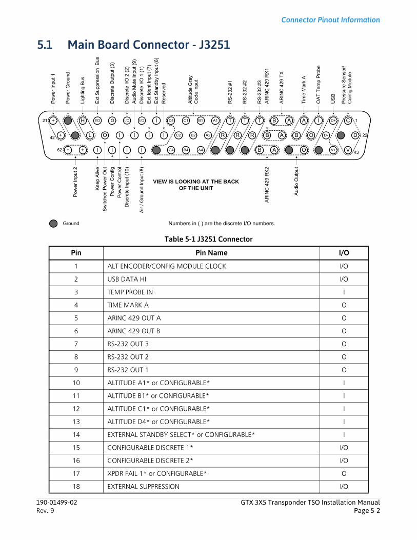
Connector Pinout Information
5.1 Main Board Connector - J3251
Table 5-1 J3251 Connector
Pin Pin Name I/O
1 ALT ENCODER/CONFIG MODULE CLOCK I/O
2 USB DATA HI I/O
3 TEMP PROBE IN I
4 TIME MARK A O
5 ARINC 429 OUT A O
6 ARINC 429 OUT B O
7 RS-232 OUT 3 O
8 RS-232 OUT 2 O
9 RS-232 OUT 1 O
10 ALTITUDE A1* or CONFIGURABLE* I
11 ALTITUDE B1* or CONFIGURABLE* I
12 ALTITUDE C1* or CONFIGURABLE* I
13 ALTITUDE D4* or CONFIGURABLE* I
14 EXTERNAL STANDBY SELECT* or CONFIGURABLE* I
15 CONFIGURABLE DISCRETE 1* I/O
16 CONFIGURABLE DISCRETE 2* I/O
17 XPDR FAIL 1* or CONFIGURABLE* O
18 EXTERNAL SUPPRESSION I/O
I/O
C4
B1 A1
I
B AO C1I/O+ H I/O
B2 A2I R B
D4
C2O+ L
21
42
Ext
Id
ent
Inp
ut (
7)
Air
/ G
roun
d In
put (
8)
Ext
Sta
ndb
y In
put
(6
)
Lig
htin
g B
us
Ext
Sup
pre
ssio
n B
us
Sw
itche
d P
ower
Out
Pow
er
Con
fig
Re
serv
ed
Alti
tude
Gra
y C
od
e In
pu
t
Pow
er In
put 1
Po
we
r G
rou
nd
AT
A D-
Ground
RS
-23
2 #
3
Dis
cret
e I/
O 1
(1)
OA
T T
emp
Pro
be
RS
-23
2 #
2
Kee
p A
live
+ + I I I62 B4 A4I B A
Pre
ssur
e S
en
sor/
C
on
fig M
odu
le
22
43
1D+I
O
I C
I
T
OI D
V+
T
R
V
US
B
RS
-23
2 #
1
BA
udi
o M
ute
Inp
ut (
9)
Dis
cret
e In
put
(10)
Dis
cret
e I/
O 2
(2)
Pow
er
Inpu
t 2
Po
we
r C
ontr
ol
Dis
cre
te O
utpu
t (3
)
R
Tim
e M
ark
A
AR
INC
429
TX
AR
INC
42
9 R
X2
Aud
io O
utp
ut
AR
INC
42
9 R
X1
Numbers in ( ) are the discrete I/O numbers.
VIEW IS LOOKING AT THE BACK OF THE UNIT
190-01499-02 GTX 3X5 Transponder TSO Installation ManualRev. 9 Page 5-2
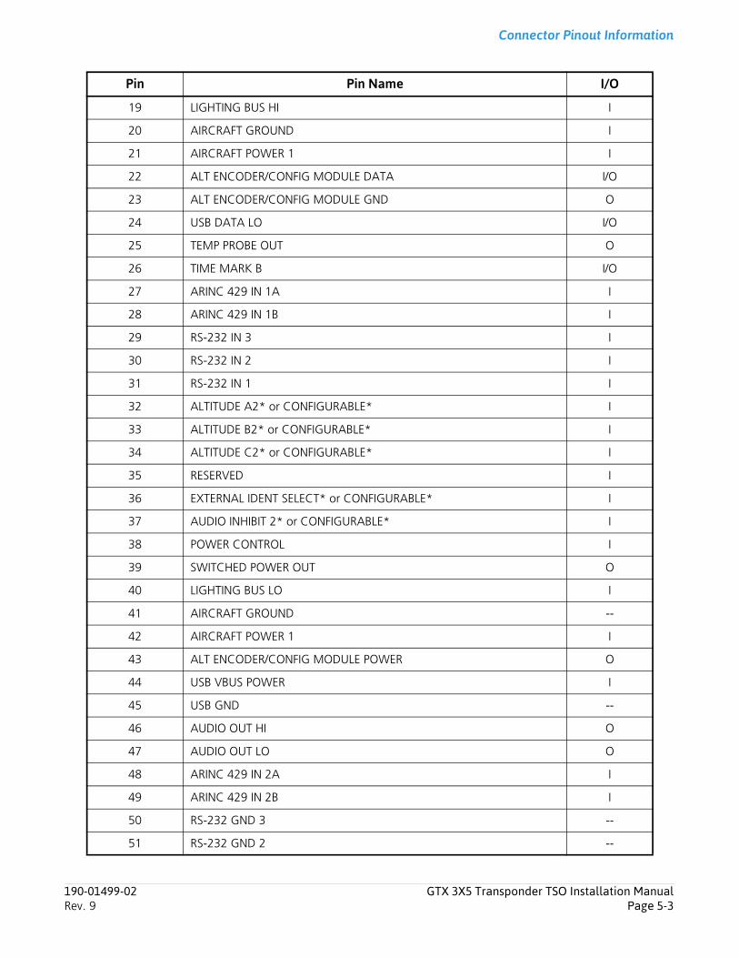
Connector Pinout Information
19 LIGHTING BUS HI I
20 AIRCRAFT GROUND I
21 AIRCRAFT POWER 1 I
22 ALT ENCODER/CONFIG MODULE DATA I/O
23 ALT ENCODER/CONFIG MODULE GND O
24 USB DATA LO I/O
25 TEMP PROBE OUT O
26 TIME MARK B I/O
27 ARINC 429 IN 1A I
28 ARINC 429 IN 1B I
29 RS-232 IN 3 I
30 RS-232 IN 2 I
31 RS-232 IN 1 I
32 ALTITUDE A2* or CONFIGURABLE* I
33 ALTITUDE B2* or CONFIGURABLE* I
34 ALTITUDE C2* or CONFIGURABLE* I
35 RESERVED I
36 EXTERNAL IDENT SELECT* or CONFIGURABLE* I
37 AUDIO INHIBIT 2* or CONFIGURABLE* I
38 POWER CONTROL I
39 SWITCHED POWER OUT O
40 LIGHTING BUS LO I
41 AIRCRAFT GROUND --
42 AIRCRAFT POWER 1 I
43 ALT ENCODER/CONFIG MODULE POWER O
44 USB VBUS POWER I
45 USB GND --
46 AUDIO OUT HI O
47 AUDIO OUT LO O
48 ARINC 429 IN 2A I
49 ARINC 429 IN 2B I
50 RS-232 GND 3 --
51 RS-232 GND 2 --
Pin Pin Name I/O
190-01499-02 GTX 3X5 Transponder TSO Installation ManualRev. 9 Page 5-3
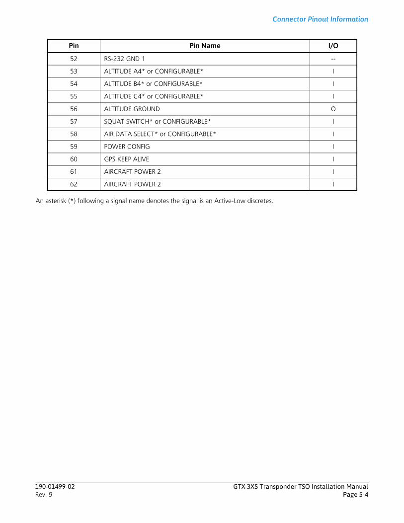
Connector Pinout Information
An asterisk (*) following a signal name denotes the signal is an Active-Low discretes.
52 RS-232 GND 1 --
53 ALTITUDE A4* or CONFIGURABLE* I
54 ALTITUDE B4* or CONFIGURABLE* I
55 ALTITUDE C4* or CONFIGURABLE* I
56 ALTITUDE GROUND O
57 SQUAT SWITCH* or CONFIGURABLE* I
58 AIR DATA SELECT* or CONFIGURABLE* I
59 POWER CONFIG I
60 GPS KEEP ALIVE I
61 AIRCRAFT POWER 2 I
62 AIRCRAFT POWER 2 I
Pin Pin Name I/O
190-01499-02 GTX 3X5 Transponder TSO Installation ManualRev. 9 Page 5-4
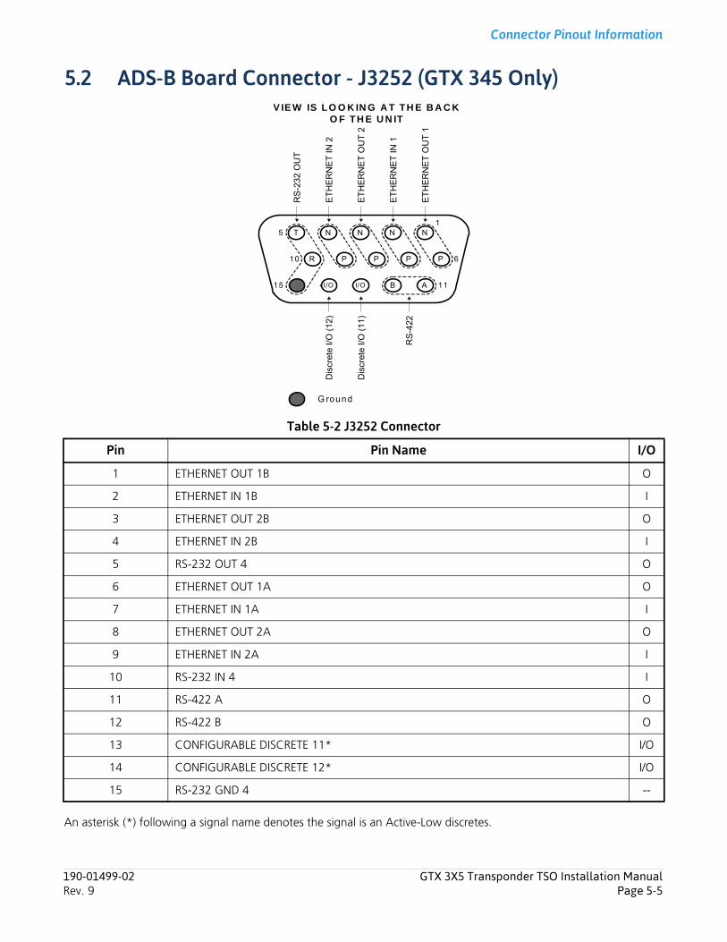
Connector Pinout Information
5.2 ADS-B Board Connector - J3252 (GTX 345 Only)
Table 5-2 J3252 Connector
An asterisk (*) following a signal name denotes the signal is an Active-Low discretes.
Pin Pin Name I/O
1 ETHERNET OUT 1B O
2 ETHERNET IN 1B I
3 ETHERNET OUT 2B O
4 ETHERNET IN 2B I
5 RS-232 OUT 4 O
6 ETHERNET OUT 1A O
7 ETHERNET IN 1A I
8 ETHERNET OUT 2A O
9 ETHERNET IN 2A I
10 RS-232 IN 4 I
11 RS-422 A O
12 RS-422 B O
13 CONFIGURABLE DISCRETE 11* I/O
14 CONFIGURABLE DISCRETE 12* I/O
15 RS-232 GND 4 --
P
NNT NN
PR PP
5
10
G round
BI/OI/O A15
1
ET
HE
RN
ET
OU
T 1
6
11
RS
-232
OU
T
ET
HE
RN
ET
OU
T 2
ET
HE
RN
ET
IN 2
ET
HE
RN
ET
IN 1
Dis
cret
e I/
O (
11)
Dis
cret
e I/
O (
12)
RS
-42
2
V IE W IS LO O K IN G A T TH E B A C K O F TH E U N IT
190-01499-02 GTX 3X5 Transponder TSO Installation ManualRev. 9 Page 5-5
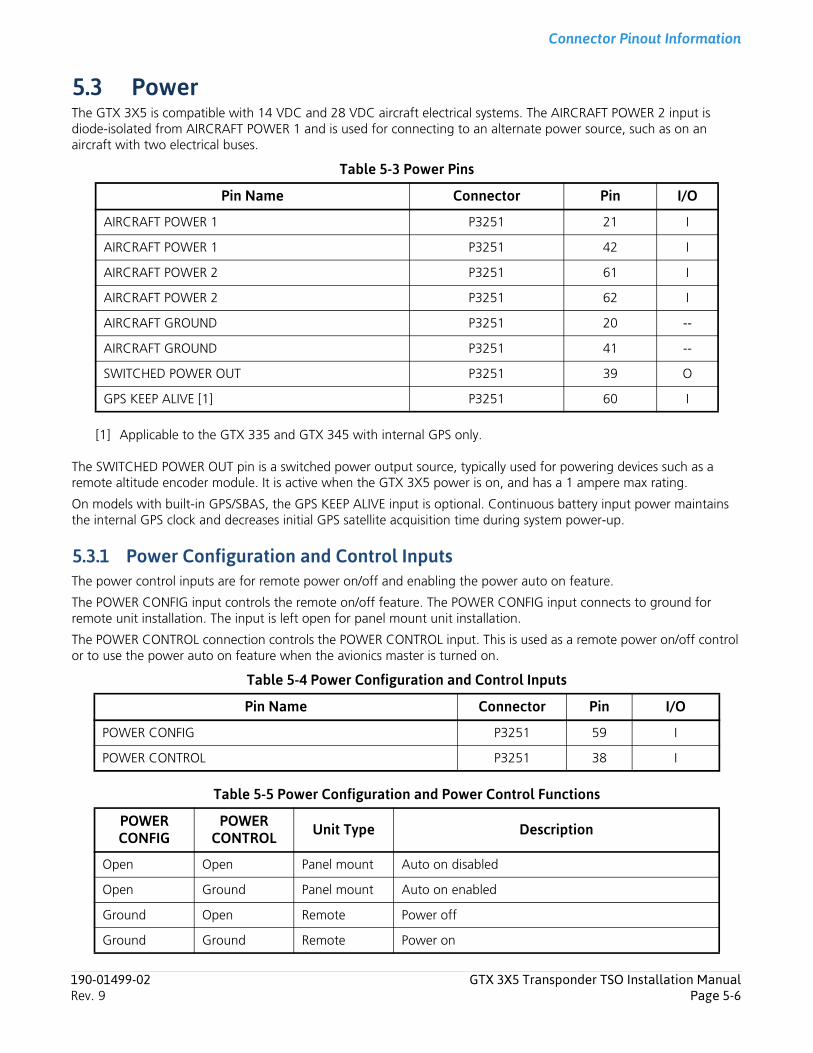
Connector Pinout Information
5.3 PowerThe GTX 3X5 is compatible with 14 VDC and 28 VDC aircraft electrical systems. The AIRCRAFT POWER 2 input is diode-isolated from AIRCRAFT POWER 1 and is used for connecting to an alternate power source, such as on an aircraft with two electrical buses.
Table 5-3 Power Pins
[1] Applicable to the GTX 335 and GTX 345 with internal GPS only.
The SWITCHED POWER OUT pin is a switched power output source, typically used for powering devices such as a remote altitude encoder module. It is active when the GTX 3X5 power is on, and has a 1 ampere max rating.
On models with built-in GPS/SBAS, the GPS KEEP ALIVE input is optional. Continuous battery input power maintains the internal GPS clock and decreases initial GPS satellite acquisition time during system power-up.
5.3.1 Power Configuration and Control InputsThe power control inputs are for remote power on/off and enabling the power auto on feature.
The POWER CONFIG input controls the remote on/off feature. The POWER CONFIG input connects to ground for remote unit installation. The input is left open for panel mount unit installation.
The POWER CONTROL connection controls the POWER CONTROL input. This is used as a remote power on/off control or to use the power auto on feature when the avionics master is turned on.
Table 5-4 Power Configuration and Control Inputs
Table 5-5 Power Configuration and Power Control Functions
Pin Name Connector Pin I/O
AIRCRAFT POWER 1 P3251 21 I
AIRCRAFT POWER 1 P3251 42 I
AIRCRAFT POWER 2 P3251 61 I
AIRCRAFT POWER 2 P3251 62 I
AIRCRAFT GROUND P3251 20 --
AIRCRAFT GROUND P3251 41 --
SWITCHED POWER OUT P3251 39 O
GPS KEEP ALIVE [1] P3251 60 I
Pin Name Connector Pin I/O
POWER CONFIG P3251 59 I
POWER CONTROL P3251 38 I
POWER CONFIG
POWER CONTROL Unit Type Description
Open Open Panel mount Auto on disabled
Open Ground Panel mount Auto on enabled
Ground Open Remote Power off
Ground Ground Remote Power on
190-01499-02 GTX 3X5 Transponder TSO Installation ManualRev. 9 Page 5-6
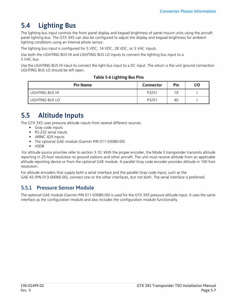
Connector Pinout Information
5.4 Lighting BusThe lighting bus input controls the front panel display and keypad brightness of panel mount units using the aircraft panel lighting bus. The GTX 3X5 can also be configured to adjust the display and keypad brightness for ambient lighting conditions using an internal photo sensor.
The lighting bus input is configured for 5 VDC, 14 VDC, 28 VDC, or 5 VAC inputs.
Use both the LIGHTING BUS HI and LIGHTING BUS LO inputs to connect the lighting bus input to a 5 VAC bus.
Use the LIGHTING BUS HI input to connect the light bus input to a DC input. The return is the unit ground connection. LIGHTING BUS LO should be left open.
Table 5-6 Lighting Bus Pins
5.5 Altitude InputsThe GTX 3X5 uses pressure altitude inputs from several different sources:
• Gray code inputs• RS-232 serial inputs• ARINC 429 inputs• The optional GAE module (Garmin P/N 011-03080-00)• HSDB
For altitude source priorities refer to section 3.10. With the proper encoder, the Mode S transponder transmits altitude reporting in 25-foot resolution to ground stations and other aircraft. The unit must receive altitude from an applicable altitude reporting device or from the optional GAE module. A parallel Gray code encoder provides altitude in 100 foot resolution.
For altitude encoders that supply both a serial interface and the parallel Gray code input, such as the GAE 43 (P/N 013-00066-00), connect one or the other interfaces, but not both. The serial interface is preferred.
5.5.1 Pressure Sensor ModuleThe optional GAE module (Garmin P/N 011-03080-00) is used for the GTX 3X5 pressure altitude input. It uses the same interface as the configuration module and also includes the configuration module functionality.
Pin Name Connector Pin I/O
LIGHTING BUS HI P3251 19 I
LIGHTING BUS LO P3251 40 I
190-01499-02 GTX 3X5 Transponder TSO Installation ManualRev. 9 Page 5-7
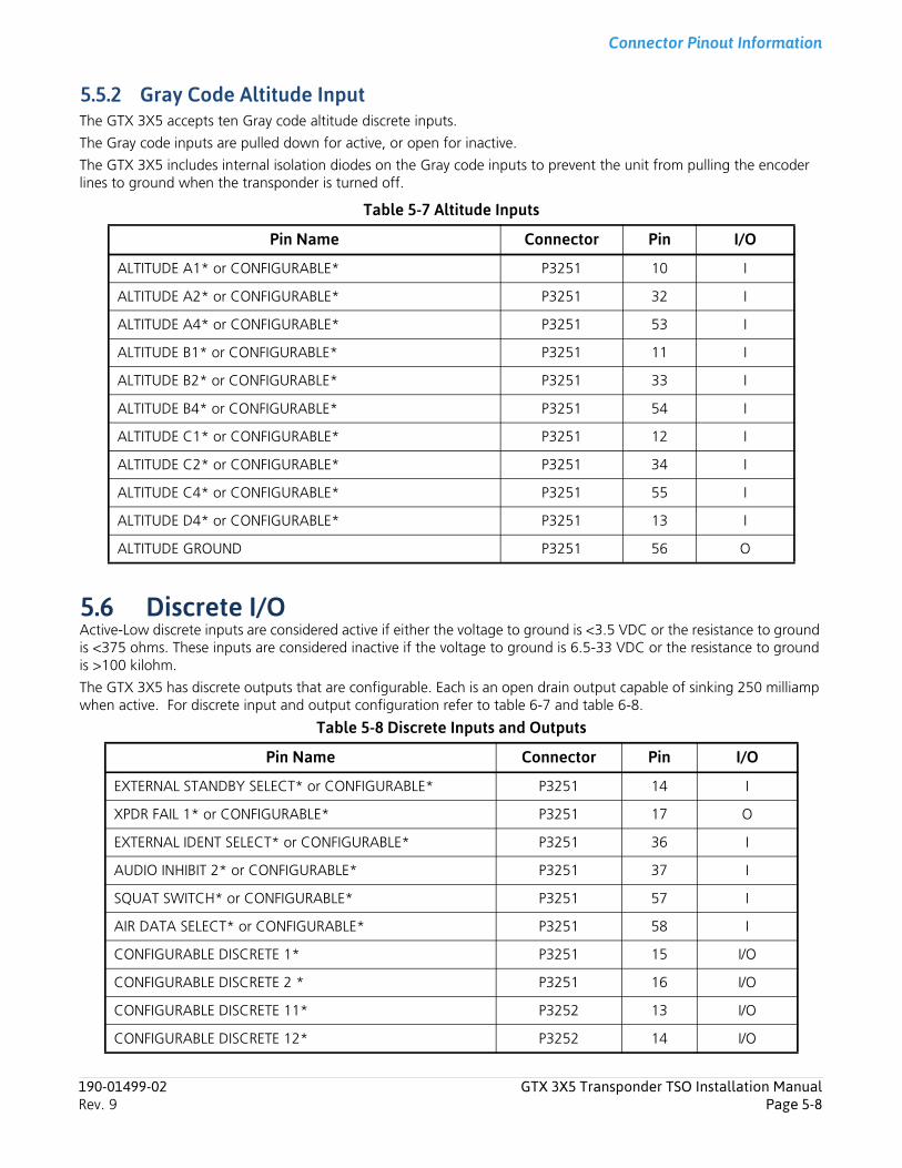
Connector Pinout Information
5.5.2 Gray Code Altitude InputThe GTX 3X5 accepts ten Gray code altitude discrete inputs.
The Gray code inputs are pulled down for active, or open for inactive.
The GTX 3X5 includes internal isolation diodes on the Gray code inputs to prevent the unit from pulling the encoder lines to ground when the transponder is turned off.
Table 5-7 Altitude Inputs
5.6 Discrete I/OActive-Low discrete inputs are considered active if either the voltage to ground is <3.5 VDC or the resistance to ground is <375 ohms. These inputs are considered inactive if the voltage to ground is 6.5-33 VDC or the resistance to ground is >100 kilohm.
The GTX 3X5 has discrete outputs that are configurable. Each is an open drain output capable of sinking 250 milliamp when active. For discrete input and output configuration refer to table 6-7 and table 6-8.
Table 5-8 Discrete Inputs and Outputs
Pin Name Connector Pin I/O
ALTITUDE A1* or CONFIGURABLE* P3251 10 I
ALTITUDE A2* or CONFIGURABLE* P3251 32 I
ALTITUDE A4* or CONFIGURABLE* P3251 53 I
ALTITUDE B1* or CONFIGURABLE* P3251 11 I
ALTITUDE B2* or CONFIGURABLE* P3251 33 I
ALTITUDE B4* or CONFIGURABLE* P3251 54 I
ALTITUDE C1* or CONFIGURABLE* P3251 12 I
ALTITUDE C2* or CONFIGURABLE* P3251 34 I
ALTITUDE C4* or CONFIGURABLE* P3251 55 I
ALTITUDE D4* or CONFIGURABLE* P3251 13 I
ALTITUDE GROUND P3251 56 O
Pin Name Connector Pin I/O
EXTERNAL STANDBY SELECT* or CONFIGURABLE* P3251 14 I
XPDR FAIL 1* or CONFIGURABLE* P3251 17 O
EXTERNAL IDENT SELECT* or CONFIGURABLE* P3251 36 I
AUDIO INHIBIT 2* or CONFIGURABLE* P3251 37 I
SQUAT SWITCH* or CONFIGURABLE* P3251 57 I
AIR DATA SELECT* or CONFIGURABLE* P3251 58 I
CONFIGURABLE DISCRETE 1* P3251 15 I/O
CONFIGURABLE DISCRETE 2 * P3251 16 I/O
CONFIGURABLE DISCRETE 11* P3252 13 I/O
CONFIGURABLE DISCRETE 12* P3252 14 I/O
190-01499-02 GTX 3X5 Transponder TSO Installation ManualRev. 9 Page 5-8
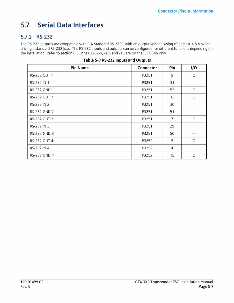
Connector Pinout Information
5.7 Serial Data Interfaces
5.7.1 RS-232The RS-232 outputs are compatible with EIA Standard RS-232C with an output voltage swing of at least ± 5 V when driving a standard RS-232 load. The RS-232 inputs and outputs can be configured for different functions depending on the installation. Refer to section 6.5. Pins P3252-5, -10, and -15 are on the GTX 345 only.
Table 5-9 RS-232 Inputs and Outputs
Pin Name Connector Pin I/O
RS-232 OUT 1 P3251 9 O
RS-232 IN 1 P3251 31 I
RS-232 GND 1 P3251 52 O
RS-232 OUT 2 P3251 8 O
RS-232 IN 2 P3251 30 I
RS-232 GND 2 P3251 51 --
RS-232 OUT 3 P3251 7 O
RS-232 IN 3 P3251 29 I
RS-232 GND 3 P3251 50 ---
RS-232 OUT 4 P3252 5 O
RS-232 IN 4 P3252 10 I
RS-232 GND 4 P3252 15 O
190-01499-02 GTX 3X5 Transponder TSO Installation ManualRev. 9 Page 5-9

Connector Pinout Information
5.7.2 ARINC 429The ARINC 429 output conforms to the ARINC 429 electrical specification when loaded with up to five standard ARINC 429 receivers. The ARINC 429 inputs and outputs can be configured for different functions depending on the installation. Refer to section 6.5.
Table 5-10 ARINC 429 Inputs and Outputs
5.7.3 HSDBTable 5-11 Ethernet Inputs and Outputs
5.7.4 RS-422The RS-422 interface conforms to the electrical specifications of EIA standard RS-422.
Table 5-12 RS-422 Outputs
Pin Name Connector Pin I/O
ARINC 429 OUT A P3251 5 O
ARINC 429 OUT B P3251 6 O
ARINC 429 IN 1A P3251 27 I
ARINC 429 IN 1B P3251 28 I
ARINC 429 IN 2A P3251 48 I
ARINC 429 IN 2B P3251 49 I
Pin Name Connector Pin I/O
ETHERNET OUT 1A P3252 6 O
ETHERNET OUT 1B P3252 1 O
ETHERNET IN 1A P3252 7 I
ETHERNET IN 1B P3252 2 I
ETHERNET OUT 2A P3252 8 O
ETHERNET OUT 2B P3252 3 O
ETHERNET IN 2A P3252 9 I
ETHERNET IN 2B P3252 4 I
Pin Name Connector Pin I/O
RS-422 A P3252 11 O
RS-422 B P3252 12 O
190-01499-02 GTX 3X5 Transponder TSO Installation ManualRev. 9 Page 5-10
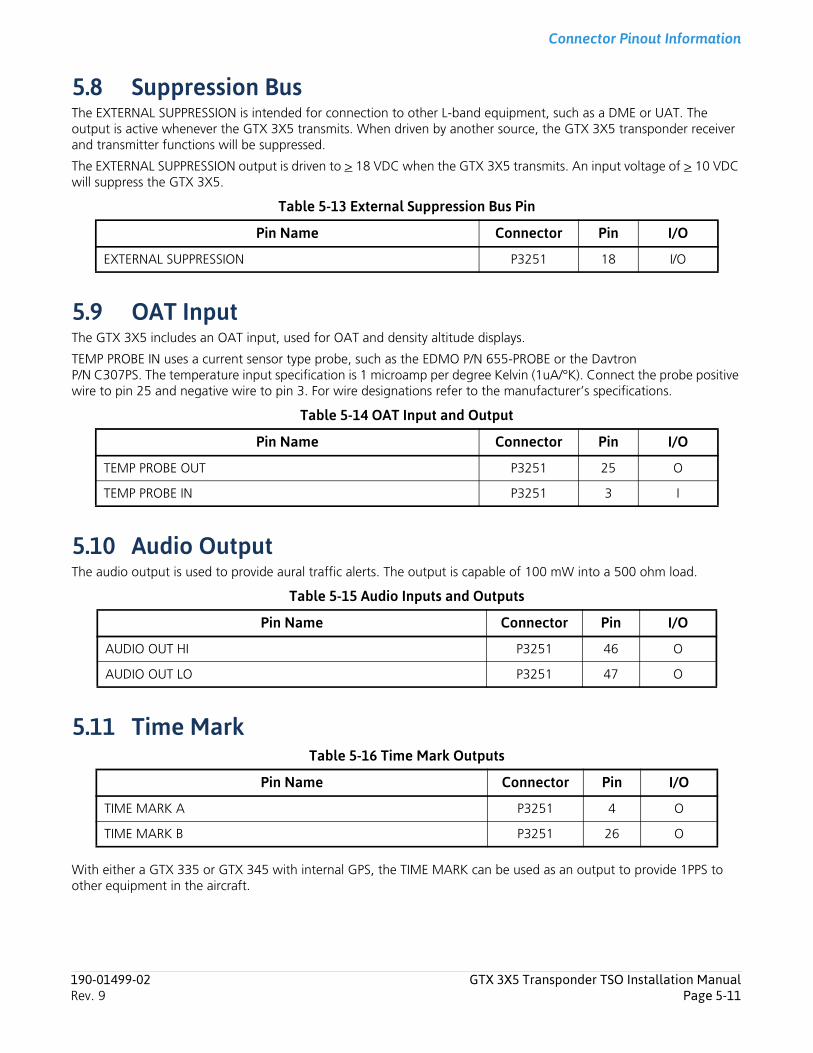
Connector Pinout Information
5.8 Suppression BusThe EXTERNAL SUPPRESSION is intended for connection to other L-band equipment, such as a DME or UAT. The output is active whenever the GTX 3X5 transmits. When driven by another source, the GTX 3X5 transponder receiver and transmitter functions will be suppressed.
The EXTERNAL SUPPRESSION output is driven to > 18 VDC when the GTX 3X5 transmits. An input voltage of > 10 VDC will suppress the GTX 3X5.
Table 5-13 External Suppression Bus Pin
5.9 OAT InputThe GTX 3X5 includes an OAT input, used for OAT and density altitude displays.
TEMP PROBE IN uses a current sensor type probe, such as the EDMO P/N 655-PROBE or the Davtron P/N C307PS. The temperature input specification is 1 microamp per degree Kelvin (1uA/°K). Connect the probe positive wire to pin 25 and negative wire to pin 3. For wire designations refer to the manufacturer’s specifications.
Table 5-14 OAT Input and Output
5.10 Audio OutputThe audio output is used to provide aural traffic alerts. The output is capable of 100 mW into a 500 ohm load.
Table 5-15 Audio Inputs and Outputs
5.11 Time MarkTable 5-16 Time Mark Outputs
With either a GTX 335 or GTX 345 with internal GPS, the TIME MARK can be used as an output to provide 1PPS to other equipment in the aircraft.
Pin Name Connector Pin I/O
EXTERNAL SUPPRESSION P3251 18 I/O
Pin Name Connector Pin I/O
TEMP PROBE OUT P3251 25 O
TEMP PROBE IN P3251 3 I
Pin Name Connector Pin I/O
AUDIO OUT HI P3251 46 O
AUDIO OUT LO P3251 47 O
Pin Name Connector Pin I/O
TIME MARK A P3251 4 O
TIME MARK B P3251 26 O
190-01499-02 GTX 3X5 Transponder TSO Installation ManualRev. 9 Page 5-11
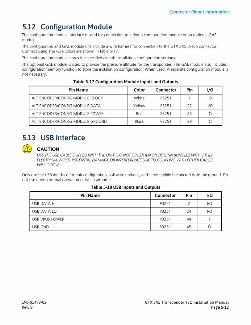
Connector Pinout Information
5.12 Configuration ModuleThe configuration module interface is used for connection to either a configuration module or an optional GAE module.
The configuration and GAE module kits include a wire harness for connection to the GTX 3X5 D-sub connector. Connect using The wire colors are shown in table 5-17.
The configuration module stores the specified aircraft installation configuration settings.
The optional GAE module is used to provide the pressure altitude for the transponder. The GAE module also includes configuration memory function to store the installation configuration. When used, A separate configuration module is not necessary.
Table 5-17 Configuration Module Inputs and Outputs
5.13 USB InterfaceCAUTIONUSE THE USB CABLE SHIPPED WITH THE UNIT. DO NOT LENGTHEN OR TIE UP IN BUNDLES WITH OTHER ELECTRICAL WIRES. POTENTIAL DAMAGE OR INTERFERENCE DUE TO COUPLING WITH OTHER CABLES WILL OCCUR.
Only use the USB interface for unit configuration, software updates, and service while the aircraft is on the ground. Do not use during normal operation or when airborne.
Table 5-18 USB Inputs and Outputs
Pin Name Color Connector Pin I/O
ALT ENCODER/CONFIG MODULE CLOCK White P3251 1 O
ALT ENCODER/CONFIG MODULE DATA Yellow P3251 22 I/O
ALT ENCODER/CONFIG MODULE POWER Red P3251 43 O
ALT ENCODER/CONFIG MODULE GROUND Black P3251 23 O
Pin Name Connector Pin I/O
USB DATA HI P3251 2 I/O
USB DATA LO P3251 24 I/O
USB VBUS POWER P3251 44 I
USB GND P3251 45 O
190-01499-02 GTX 3X5 Transponder TSO Installation ManualRev. 9 Page 5-12
Post Installation Configuration & Checkout
6 Post Installation Configuration & Checkout6.1 System Configuration Overview ..................................................................................................................... 6-16.2 Mounting, Wiring, and Power Checks............................................................................................................ 6-16.3 Configuration Mode and Settings .................................................................................................................. 6-26.4 Audio Settings ............................................................................................................................................... 6-36.5 Interfaces....................................................................................................................................................... 6-56.6 Unit Settings................................................................................................................................................ 6-146.7 Display Pages............................................................................................................................................... 6-176.8 Sensors........................................................................................................................................................ 6-216.9 ADSB........................................................................................................................................................... 6-276.10 Diagnostics .................................................................................................................................................. 6-326.11 Remote Unit Configuration.......................................................................................................................... 6-336.12 Ground Check - GPS Reception Check......................................................................................................... 6-336.13 Ground Check - Transponder....................................................................................................................... 6-346.14 Software Installation Procedure.................................................................................................................... 6-34
6.1 System Configuration OverviewThe required GTX 3X5 configuration and checkout procedures are as follows:
1. Complete the installation checks.
2. Configure the GTX 3X5 for the specified installation.
3. Complete ground checks to make sure it interfaces to external equipment.
For additional checkout procedures, refer to GTX 3X5 Mode A/C Lock Enablement Guide.
6.2 Mounting, Wiring, and Power ChecksCAUTIONMAKE SURE ALL LIGHTING BUSES ARE TURNED TO THEIR LOWEST ADJUSTMENT BEFORE APPLYING POWER TO THE UNIT. THE LOWEST ADJUSTMENT PREVENTS DAMAGE TO THE UNIT IF THERE ARE ANY WIRING ERRORS.
Examine the wire harness to make sure the connection to aircraft systems and avionics equipment is correct before the unit is energized. Point-to-point continuity must be examined to expose any faults such as shorting to ground or wiring discrepancies. All faults or discrepancies must be corrected before continuing.
Before and during the installation make sure:
1. All cables are properly attached.
2. Shields are connected to connector shield blocks.
3. Movement of the flight and engine controls through the full range of motion do not touch cabling and control systems.
4. Wire is installed as described in section 3.17.
Make sure these items are completed after the installation or a continuity check.
1. Power and ground checks.
2. Faults and discrepancies are corrected.
3. Installation rack is correctly attached.
4. Unit is correctly seated in the installation rack.
190-01499-02 GTX 3X5 Transponder TSO Installation ManualRev. 9 Page 6-1
Post Installation Configuration & Checkout
6.3 Configuration Mode and SettingsNOTEScreenshots are for illustrative purposes only. They do not imply the shown setting(s) should be used in any installation.
System and interface settings are shown in configuration mode and are unique to the GTX 3X5 installation. The configuration settings are stored in internal memory. If connected, the configuration module stores configuration settings. The optional GAE module operates as a configuration module. In this section, configuration instructions are for panel mount units. To configure remote units refer to section 6.11.
To enter configuration mode on a panel mount unit, push and hold ENT and apply power.
• Push and hold OFF until the unit powers off to exit configuration mode.• Push FUNC to cycle through the group pages.• Push 8 or 9 to scroll up or down on the page without an active field selected.• Push CRSR to access items on the page.• Push 8 or 9 to cycle through the selections of an item on the page.• Push ENT to move within the page with a field highlighted or to accept setting.• Push CLR to move to previous selection on the page.• Push FUNC to exit the page.
190-01499-02 GTX 3X5 Transponder TSO Installation ManualRev. 9 Page 6-2
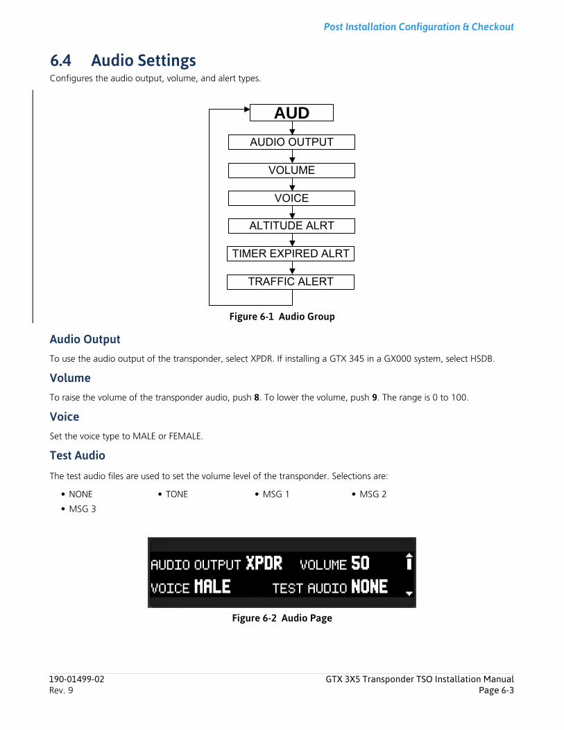
Post Installation Configuration & Checkout
6.4 Audio Settings Configures the audio output, volume, and alert types.
Figure 6-1 Audio Group
Audio OutputTo use the audio output of the transponder, select XPDR. If installing a GTX 345 in a GX000 system, select HSDB.
VolumeTo raise the volume of the transponder audio, push 8. To lower the volume, push 9. The range is 0 to 100.
VoiceSet the voice type to MALE or FEMALE.
Test Audio
The test audio files are used to set the volume level of the transponder. Selections are:
Figure 6-2 Audio Page
• NONE • TONE • MSG 1 • MSG 2
• MSG 3
AUD
TIMER EXPIRED ALRT
TRAFFIC ALERT
VOICE
VOLUME
AUDIO OUTPUT
ALTITUDE ALRT
190-01499-02 GTX 3X5 Transponder TSO Installation ManualRev. 9 Page 6-3
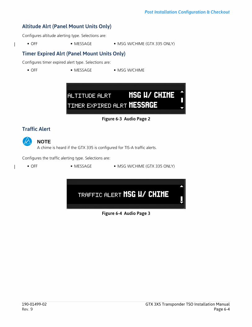
Post Installation Configuration & Checkout
Altitude Alrt (Panel Mount Units Only)
Configures altitude alerting type. Selections are:
Timer Expired Alrt (Panel Mount Units Only)Configures timer expired alert type. Selections are:
Figure 6-3 Audio Page 2
Traffic Alert
NOTEA chime is heard if the GTX 335 is configured for TIS-A traffic alerts.
Configures the traffic alerting type. Selections are:
Figure 6-4 Audio Page 3
• OFF • MESSAGE • MSG W/CHIME (GTX 335 ONLY)
• OFF • MESSAGE • MSG W/CHIME
• OFF • MESSAGE • MSG W/CHIME (GTX 335 ONLY)
190-01499-02 GTX 3X5 Transponder TSO Installation ManualRev. 9 Page 6-4
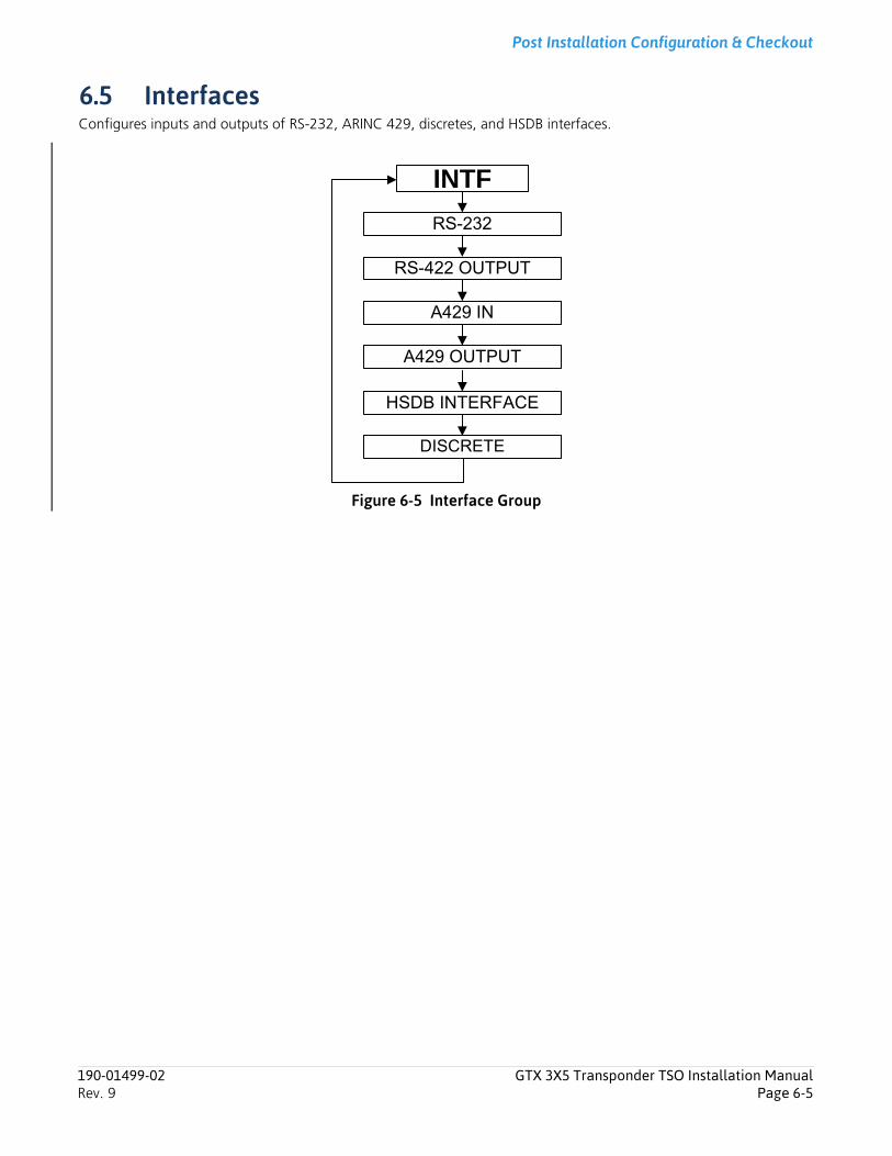
Post Installation Configuration & Checkout
6.5 InterfacesConfigures inputs and outputs of RS-232, ARINC 429, discretes, and HSDB interfaces.
Figure 6-5 Interface Group
INTF
DISCRETE
A429 OUTPUT
A429 IN
RS-422 OUTPUT
RS-232
HSDB INTERFACE
190-01499-02 GTX 3X5 Transponder TSO Installation ManualRev. 9 Page 6-5
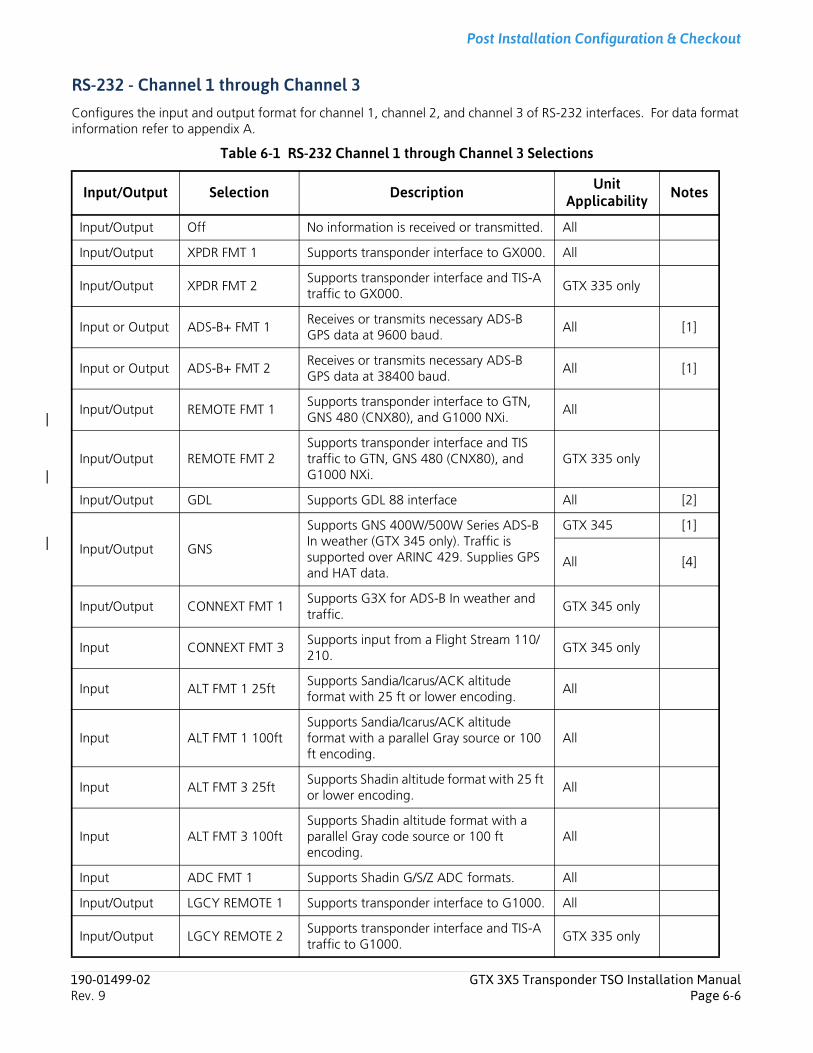
Post Installation Configuration & Checkout
RS-232 - Channel 1 through Channel 3Configures the input and output format for channel 1, channel 2, and channel 3 of RS-232 interfaces. For data format information refer to appendix A.
Table 6-1 RS-232 Channel 1 through Channel 3 Selections
Input/Output Selection Description Unit Applicability Notes
Input/Output Off No information is received or transmitted. All
Input/Output XPDR FMT 1 Supports transponder interface to GX000. All
Input/Output XPDR FMT 2Supports transponder interface and TIS-A traffic to GX000.
GTX 335 only
Input or Output ADS-B+ FMT 1Receives or transmits necessary ADS-B GPS data at 9600 baud.
All [1]
Input or Output ADS-B+ FMT 2Receives or transmits necessary ADS-B GPS data at 38400 baud.
All [1]
Input/Output REMOTE FMT 1Supports transponder interface to GTN, GNS 480 (CNX80), and G1000 NXi.
All
Input/Output REMOTE FMT 2Supports transponder interface and TIS traffic to GTN, GNS 480 (CNX80), and G1000 NXi.
GTX 335 only
Input/Output GDL Supports GDL 88 interface All [2]
Input/Output GNS
Supports GNS 400W/500W Series ADS-B In weather (GTX 345 only). Traffic is supported over ARINC 429. Supplies GPS and HAT data.
GTX 345 [1]
All [4]
Input/Output CONNEXT FMT 1Supports G3X for ADS-B In weather and traffic.
GTX 345 only
Input CONNEXT FMT 3Supports input from a Flight Stream 110/210.
GTX 345 only
Input ALT FMT 1 25ftSupports Sandia/Icarus/ACK altitude format with 25 ft or lower encoding.
All
Input ALT FMT 1 100ftSupports Sandia/Icarus/ACK altitude format with a parallel Gray source or 100 ft encoding.
All
Input ALT FMT 3 25ftSupports Shadin altitude format with 25 ft or lower encoding.
All
Input ALT FMT 3 100ftSupports Shadin altitude format with a parallel Gray code source or 100 ft encoding.
All
Input ADC FMT 1 Supports Shadin G/S/Z ADC formats. All
Input/Output LGCY REMOTE 1 Supports transponder interface to G1000. All
Input/Output LGCY REMOTE 2Supports transponder interface and TIS-A traffic to G1000.
GTX 335 only
190-01499-02 GTX 3X5 Transponder TSO Installation ManualRev. 9 Page 6-6
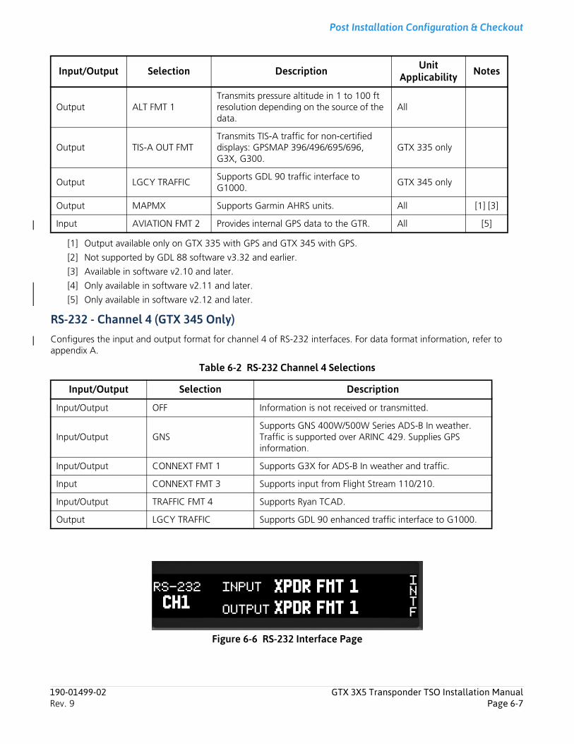
Post Installation Configuration & Checkout
[1] Output available only on GTX 335 with GPS and GTX 345 with GPS.
[2] Not supported by GDL 88 software v3.32 and earlier.
[3] Available in software v2.10 and later.
[4] Only available in software v2.11 and later.
[5] Only available in software v2.12 and later.
RS-232 - Channel 4 (GTX 345 Only)Configures the input and output format for channel 4 of RS-232 interfaces. For data format information, refer to appendix A.
Table 6-2 RS-232 Channel 4 Selections
Figure 6-6 RS-232 Interface Page
Output ALT FMT 1Transmits pressure altitude in 1 to 100 ft resolution depending on the source of the data.
All
Output TIS-A OUT FMTTransmits TIS-A traffic for non-certified displays: GPSMAP 396/496/695/696, G3X, G300.
GTX 335 only
Output LGCY TRAFFICSupports GDL 90 traffic interface to G1000.
GTX 345 only
Output MAPMX Supports Garmin AHRS units. All [1] [3]
Input AVIATION FMT 2 Provides internal GPS data to the GTR. All [5]
Input/Output Selection Description
Input/Output OFF Information is not received or transmitted.
Input/Output GNSSupports GNS 400W/500W Series ADS-B In weather. Traffic is supported over ARINC 429. Supplies GPS information.
Input/Output CONNEXT FMT 1 Supports G3X for ADS-B In weather and traffic.
Input CONNEXT FMT 3 Supports input from Flight Stream 110/210.
Input/Output TRAFFIC FMT 4 Supports Ryan TCAD.
Output LGCY TRAFFIC Supports GDL 90 enhanced traffic interface to G1000.
Input/Output Selection Description Unit Applicability Notes
190-01499-02 GTX 3X5 Transponder TSO Installation ManualRev. 9 Page 6-7
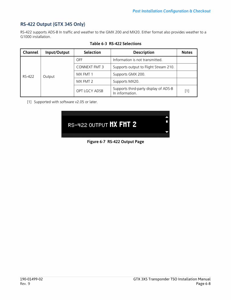
Post Installation Configuration & Checkout
RS-422 Output (GTX 345 Only)RS-422 supports ADS-B In traffic and weather to the GMX 200 and MX20. Either format also provides weather to a G1000 installation.
Table 6-3 RS-422 Selections
[1] Supported with software v2.05 or later.
Figure 6-7 RS-422 Output Page
Channel Input/Output Selection Description Notes
RS-422 Output
OFF Information is not transmitted.
CONNEXT FMT 3 Supports output to Flight Stream 210.
MX FMT 1 Supports GMX 200.
MX FMT 2 Supports MX20.
OPT LGCY ADSBSupports third-party display of ADS-B In information.
[1]
190-01499-02 GTX 3X5 Transponder TSO Installation ManualRev. 9 Page 6-8
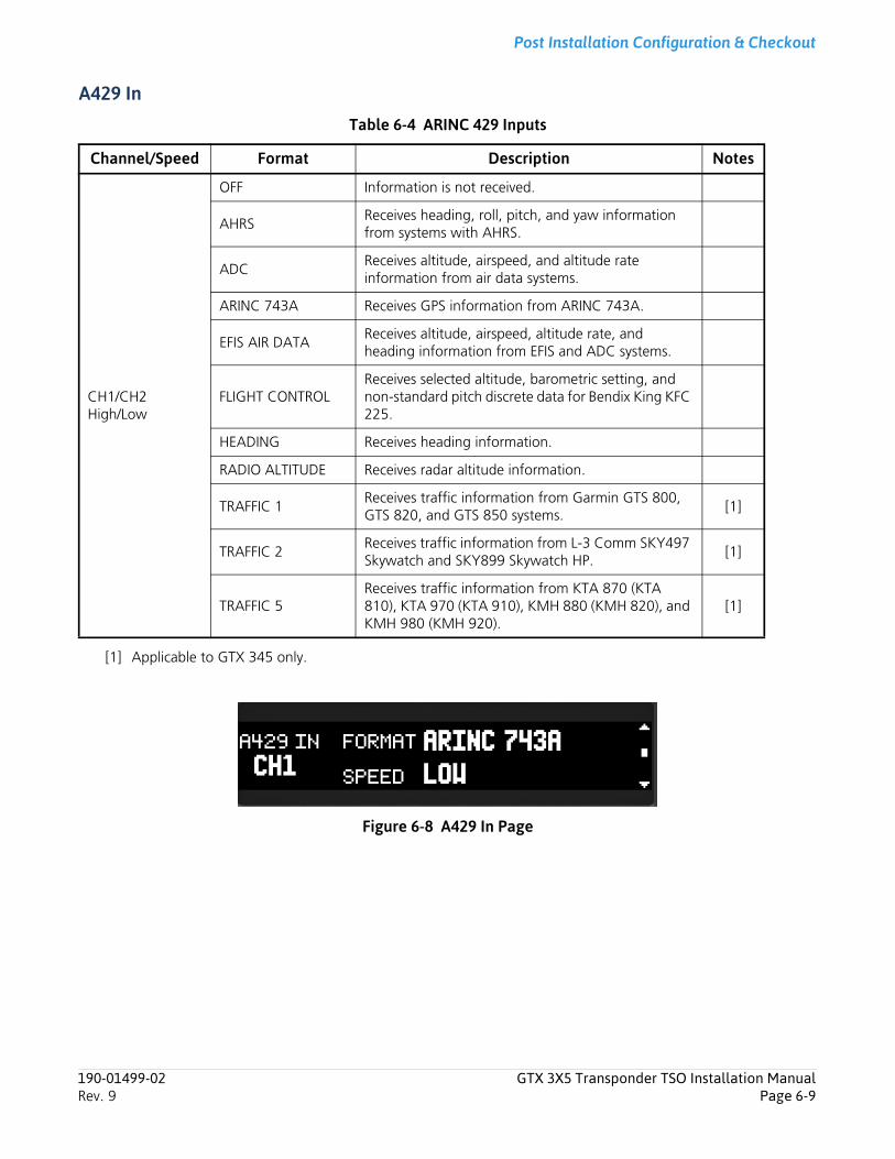
Post Installation Configuration & Checkout
A429 In
Table 6-4 ARINC 429 Inputs
[1] Applicable to GTX 345 only.
Figure 6-8 A429 In Page
Channel/Speed Format Description Notes
CH1/CH2High/Low
OFF Information is not received.
AHRSReceives heading, roll, pitch, and yaw information from systems with AHRS.
ADCReceives altitude, airspeed, and altitude rate information from air data systems.
ARINC 743A Receives GPS information from ARINC 743A.
EFIS AIR DATAReceives altitude, airspeed, altitude rate, and heading information from EFIS and ADC systems.
FLIGHT CONTROLReceives selected altitude, barometric setting, and non-standard pitch discrete data for Bendix King KFC 225.
HEADING Receives heading information.
RADIO ALTITUDE Receives radar altitude information.
TRAFFIC 1Receives traffic information from Garmin GTS 800, GTS 820, and GTS 850 systems.
[1]
TRAFFIC 2Receives traffic information from L-3 Comm SKY497 Skywatch and SKY899 Skywatch HP.
[1]
TRAFFIC 5Receives traffic information from KTA 870 (KTA 810), KTA 970 (KTA 910), KMH 880 (KMH 820), and KMH 980 (KMH 920).
[1]
190-01499-02 GTX 3X5 Transponder TSO Installation ManualRev. 9 Page 6-9
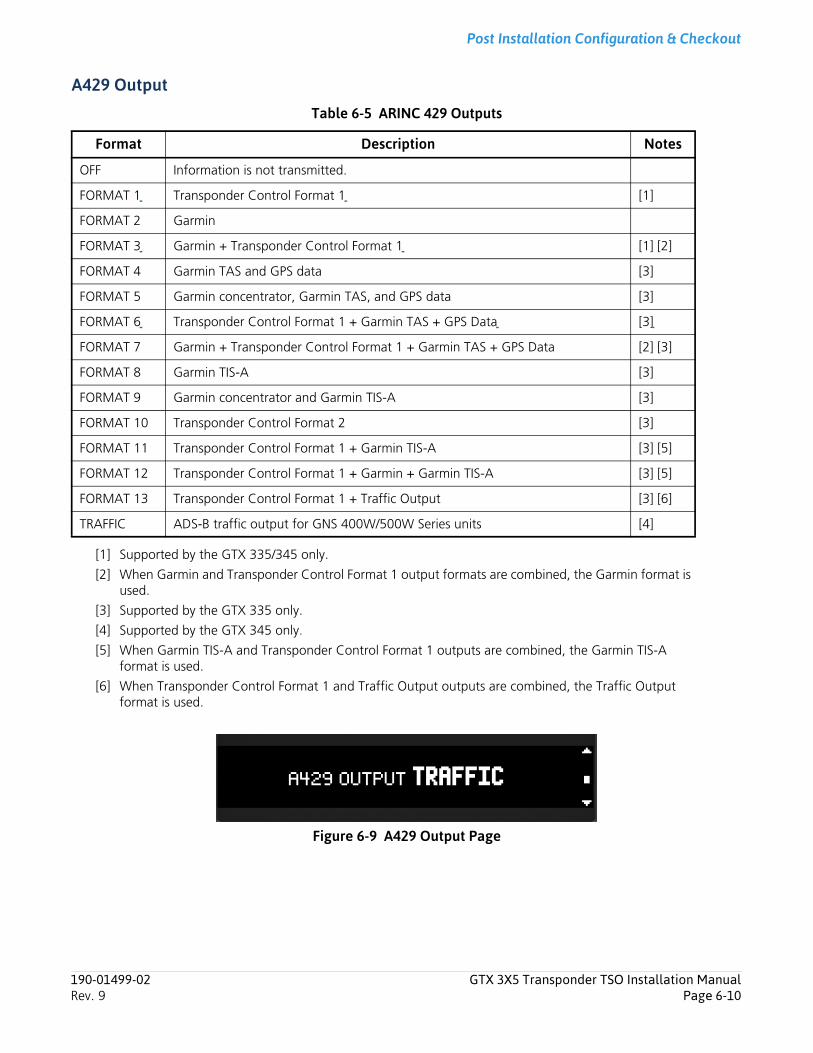
Post Installation Configuration & Checkout
A429 Output
Table 6-5 ARINC 429 Outputs
[1] Supported by the GTX 335/345 only.
[2] When Garmin and Transponder Control Format 1 output formats are combined, the Garmin format is used.
[3] Supported by the GTX 335 only.
[4] Supported by the GTX 345 only.
[5] When Garmin TIS-A and Transponder Control Format 1 outputs are combined, the Garmin TIS-A format is used.
[6] When Transponder Control Format 1 and Traffic Output outputs are combined, the Traffic Output format is used.
Figure 6-9 A429 Output Page
Format Description Notes
OFF Information is not transmitted.
FORMAT 1 Transponder Control Format 1 [1]
FORMAT 2 Garmin
FORMAT 3 Garmin + Transponder Control Format 1 [1] [2]
FORMAT 4 Garmin TAS and GPS data [3]
FORMAT 5 Garmin concentrator, Garmin TAS, and GPS data [3]
FORMAT 6 Transponder Control Format 1 + Garmin TAS + GPS Data [3]
FORMAT 7 Garmin + Transponder Control Format 1 + Garmin TAS + GPS Data [2] [3]
FORMAT 8 Garmin TIS-A [3]
FORMAT 9 Garmin concentrator and Garmin TIS-A [3]
FORMAT 10 Transponder Control Format 2 [3]
FORMAT 11 Transponder Control Format 1 + Garmin TIS-A [3] [5]
FORMAT 12 Transponder Control Format 1 + Garmin + Garmin TIS-A [3] [5]
FORMAT 13 Transponder Control Format 1 + Traffic Output [3] [6]
TRAFFIC ADS-B traffic output for GNS 400W/500W Series units [4]
190-01499-02 GTX 3X5 Transponder TSO Installation ManualRev. 9 Page 6-10
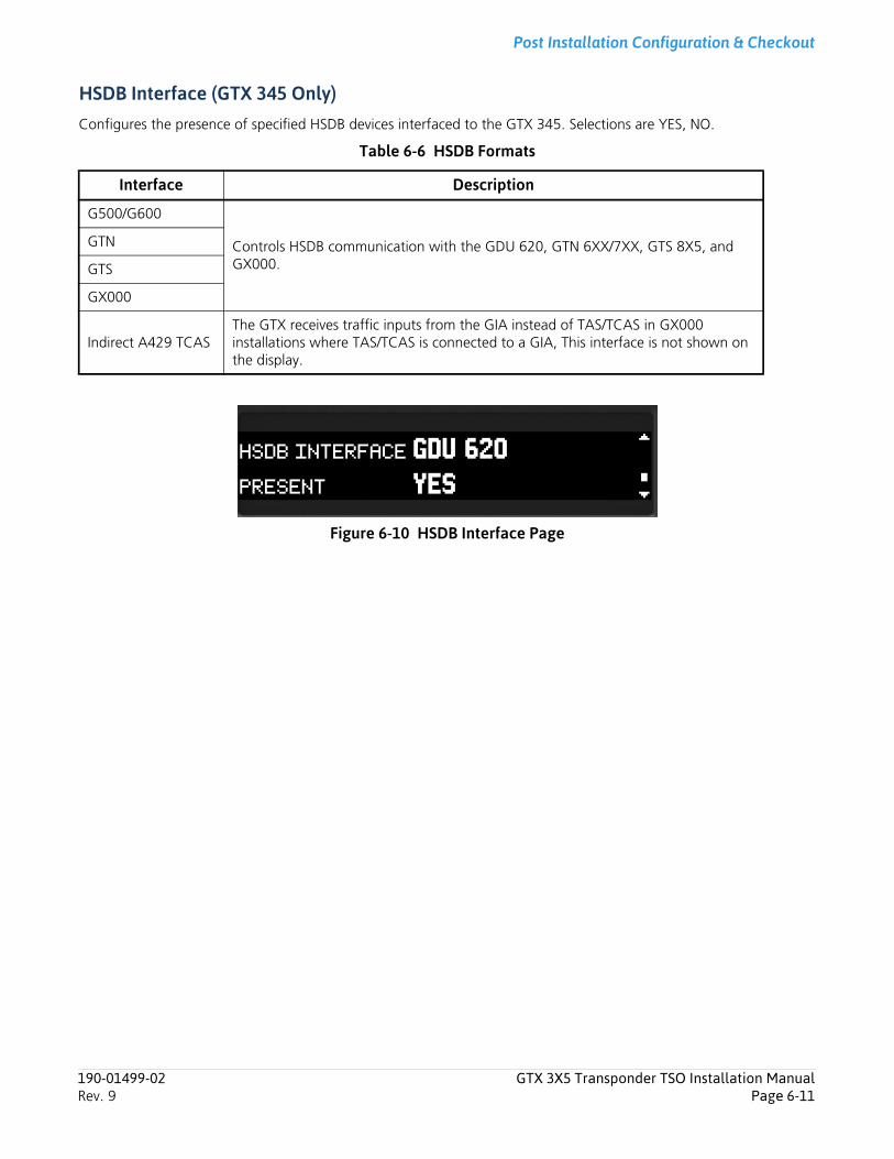
Post Installation Configuration & Checkout
HSDB Interface (GTX 345 Only)Configures the presence of specified HSDB devices interfaced to the GTX 345. Selections are YES, NO.
Table 6-6 HSDB Formats
Figure 6-10 HSDB Interface Page
Interface Description
G500/G600
Controls HSDB communication with the GDU 620, GTN 6XX/7XX, GTS 8X5, and GX000.
GTN
GTS
GX000
Indirect A429 TCASThe GTX receives traffic inputs from the GIA instead of TAS/TCAS in GX000 installations where TAS/TCAS is connected to a GIA, This interface is not shown on the display.
190-01499-02 GTX 3X5 Transponder TSO Installation ManualRev. 9 Page 6-11
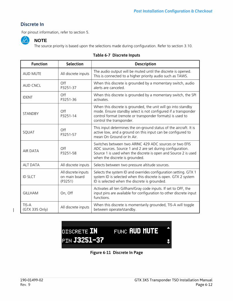
Post Installation Configuration & Checkout
Discrete In For pinout information, refer to section 5.
NOTEThe source priority is based upon the selections made during configuration. Refer to section 3.10.
Table 6-7 Discrete Inputs
Figure 6-11 Discrete In Page
Function Selection Description
AUD MUTE All discrete inputsThe audio output will be muted until the discrete is opened. This is connected to a higher priority audio such as TAWS.
AUD CNCLOffP3251-37
When this discrete is grounded by a momentary switch, audio alerts are canceled.
IDENTOffP3251-36
When this discrete is grounded by a momentary switch, the SPI activates.
STANDBYOffP3251-14
When this discrete is grounded, the unit will go into standby mode. Ensure standby select is not configured if a transponder control format (remote or transponder formats) is used to control the transponder.
SQUATOffP3251-57
This input determines the on-ground status of the aircraft. It is active low, and a ground on this input can be configured to mean On Ground or In Air.
AIR DATAOffP3251-58
Switches between two ARINC 429 ADC sources or two EFIS ADC sources. Source 1 and 2 are set during configuration. Source 1 is used when the discrete is open and Source 2 is used when the discrete is grounded.
ALT DATA All discrete inputs Selects between two pressure altitude sources.
ID SLCTAll discrete inputs on main board (P3251)
Selects the system ID and overrides configuration setting. GTX 1 system ID is selected when this discrete is open. GTX 2 system ID is selected when the discrete is grounded.
GILLHAM On, OffActivates all ten Gillham/Gray code inputs. If set to OFF, the input pins are available for configuration to other discrete input functions.
TIS-A (GTX 335 Only)
All discrete inputsWhen this discrete is momentarily grounded, TIS-A will toggle between operate/standby.
190-01499-02 GTX 3X5 Transponder TSO Installation ManualRev. 9 Page 6-12
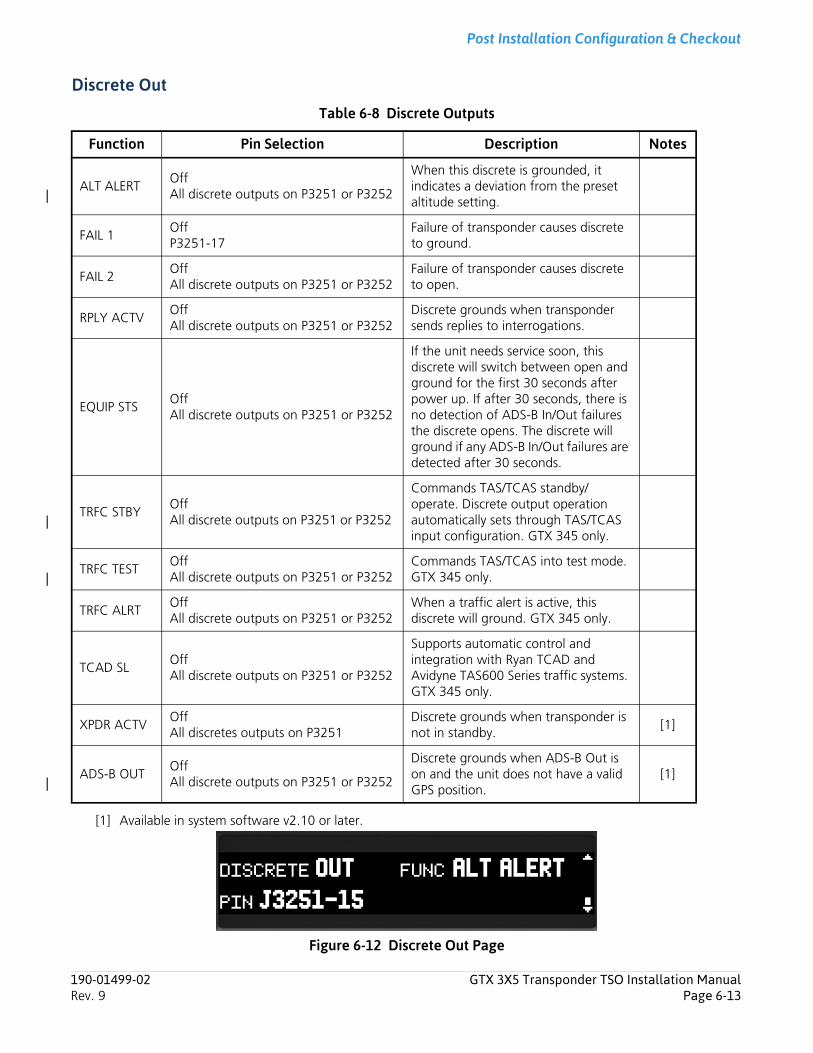
Post Installation Configuration & Checkout
Discrete Out
Table 6-8 Discrete Outputs
[1] Available in system software v2.10 or later.
Figure 6-12 Discrete Out Page
Function Pin Selection Description Notes
ALT ALERTOffAll discrete outputs on P3251 or P3252
When this discrete is grounded, it indicates a deviation from the preset altitude setting.
FAIL 1OffP3251-17
Failure of transponder causes discrete to ground.
FAIL 2OffAll discrete outputs on P3251 or P3252
Failure of transponder causes discrete to open.
RPLY ACTVOffAll discrete outputs on P3251 or P3252
Discrete grounds when transponder sends replies to interrogations.
EQUIP STSOffAll discrete outputs on P3251 or P3252
If the unit needs service soon, this discrete will switch between open and ground for the first 30 seconds after power up. If after 30 seconds, there is no detection of ADS-B In/Out failures the discrete opens. The discrete will ground if any ADS-B In/Out failures are detected after 30 seconds.
TRFC STBYOffAll discrete outputs on P3251 or P3252
Commands TAS/TCAS standby/operate. Discrete output operation automatically sets through TAS/TCAS input configuration. GTX 345 only.
TRFC TESTOffAll discrete outputs on P3251 or P3252
Commands TAS/TCAS into test mode. GTX 345 only.
TRFC ALRTOffAll discrete outputs on P3251 or P3252
When a traffic alert is active, this discrete will ground. GTX 345 only.
TCAD SLOff All discrete outputs on P3251 or P3252
Supports automatic control and integration with Ryan TCAD and Avidyne TAS600 Series traffic systems. GTX 345 only.
XPDR ACTVOffAll discretes outputs on P3251
Discrete grounds when transponder is not in standby.
[1]
ADS-B OUTOffAll discrete outputs on P3251 or P3252
Discrete grounds when ADS-B Out is on and the unit does not have a valid GPS position.
[1]
190-01499-02 GTX 3X5 Transponder TSO Installation ManualRev. 9 Page 6-13
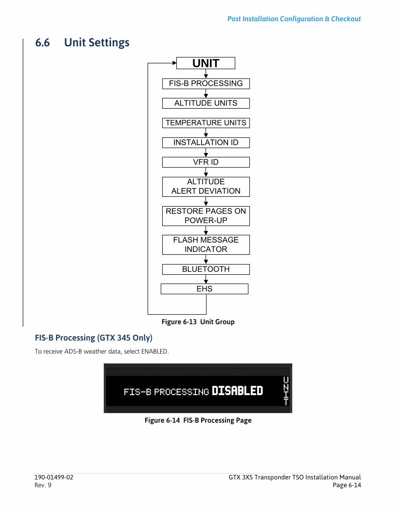
Post Installation Configuration & Checkout
6.6 Unit Settings
Figure 6-13 Unit Group
FIS-B Processing (GTX 345 Only)To receive ADS-B weather data, select ENABLED.
Figure 6-14 FIS-B Processing Page
UNIT
EHS
INSTALLATION ID
TEMPERATURE UNITS
ALTITUDE UNITS
FIS-B PROCESSING
ALTITUDE ALERT DEVIATION
VFR ID
RESTORE PAGES ON POWER-UP
FLASH MESSAGE INDICATOR
BLUETOOTH
190-01499-02 GTX 3X5 Transponder TSO Installation ManualRev. 9 Page 6-14
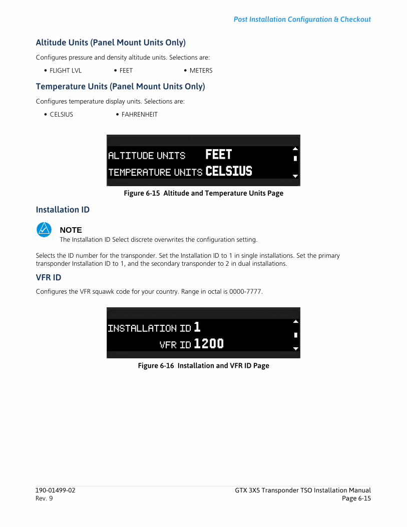
Post Installation Configuration & Checkout
Altitude Units (Panel Mount Units Only)
Configures pressure and density altitude units. Selections are:
Temperature Units (Panel Mount Units Only)
Configures temperature display units. Selections are:
Figure 6-15 Altitude and Temperature Units Page
Installation ID
NOTEThe Installation ID Select discrete overwrites the configuration setting.
Selects the ID number for the transponder. Set the Installation ID to 1 in single installations. Set the primary transponder Installation ID to 1, and the secondary transponder to 2 in dual installations.
VFR IDConfigures the VFR squawk code for your country. Range in octal is 0000-7777.
Figure 6-16 Installation and VFR ID Page
• FLIGHT LVL • FEET • METERS
• CELSIUS • FAHRENHEIT
190-01499-02 GTX 3X5 Transponder TSO Installation ManualRev. 9 Page 6-15
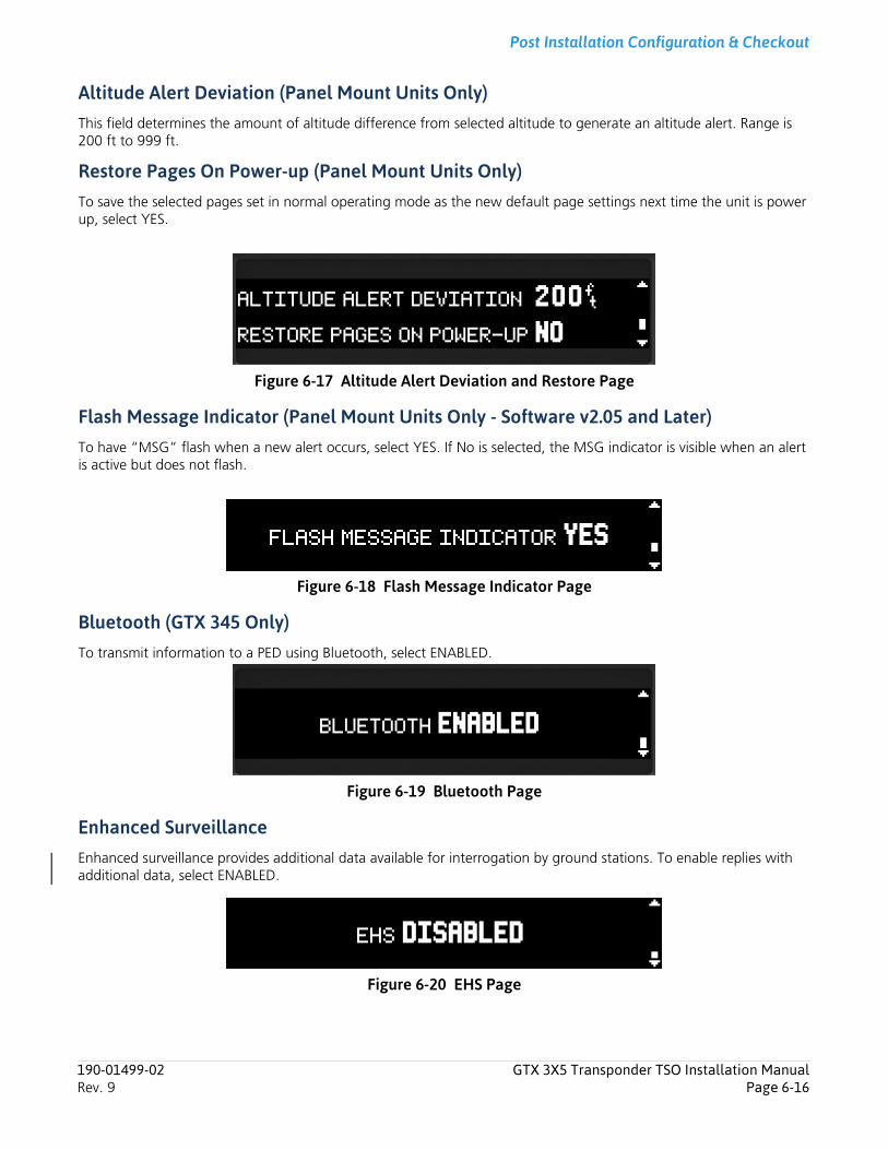
Post Installation Configuration & Checkout
Altitude Alert Deviation (Panel Mount Units Only)This field determines the amount of altitude difference from selected altitude to generate an altitude alert. Range is 200 ft to 999 ft.
Restore Pages On Power-up (Panel Mount Units Only)To save the selected pages set in normal operating mode as the new default page settings next time the unit is power up, select YES.
Figure 6-17 Altitude Alert Deviation and Restore Page
Flash Message Indicator (Panel Mount Units Only - Software v2.05 and Later)To have “MSG” flash when a new alert occurs, select YES. If No is selected, the MSG indicator is visible when an alert is active but does not flash.
Figure 6-18 Flash Message Indicator Page
Bluetooth (GTX 345 Only)To transmit information to a PED using Bluetooth, select ENABLED.
Figure 6-19 Bluetooth Page
Enhanced SurveillanceEnhanced surveillance provides additional data available for interrogation by ground stations. To enable replies with additional data, select ENABLED.
Figure 6-20 EHS Page
190-01499-02 GTX 3X5 Transponder TSO Installation ManualRev. 9 Page 6-16

Post Installation Configuration & Checkout
6.7 Display PagesNOTEMake sure the brightness levels match the lighting levels of other equipment in the panel under night conditions.
Figure 6-21 Display Group
DISP
OFFSET
LIGHTING BUS INPUT VLTG
MINIMUM LEVEL
KEYPAD BACKLIGHT
MINIMUM LEVEL
DISPLAY BACKLIGHT
SLOPE
PHOTOCELL TRANSITION
SLOPE
OFFSET
DEFAULT BACKLIGHT OFFSET
DEFAULT CONTRAST OFFSET
190-01499-02 GTX 3X5 Transponder TSO Installation ManualRev. 9 Page 6-17
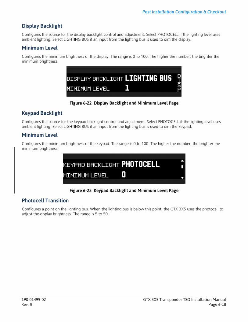
Post Installation Configuration & Checkout
Display BacklightConfigures the source for the display backlight control and adjustment. Select PHOTOCELL if the lighting level uses ambient lighting. Select LIGHTING BUS if an input from the lighting bus is used to dim the display.
Minimum LevelConfigures the minimum brightness of the display. The range is 0 to 100. The higher the number, the brighter the minimum brightness.
Figure 6-22 Display Backlight and Minimum Level Page
Keypad BacklightConfigures the source for the keypad backlight control and adjustment. Select PHOTOCELL if the lighting level uses ambient lighting. Select LIGHTING BUS if an input from the lighting bus is used to dim the keypad.
Minimum LevelConfigures the minimum brightness of the keypad. The range is 0 to 100. The higher the number, the brighter the minimum brightness.
Figure 6-23 Keypad Backlight and Minimum Level Page
Photocell TransitionConfigures a point on the lighting bus. When the lighting bus is below this point, the GTX 3X5 uses the photocell to adjust the display brightness. The range is 5 to 50.
190-01499-02 GTX 3X5 Transponder TSO Installation ManualRev. 9 Page 6-18
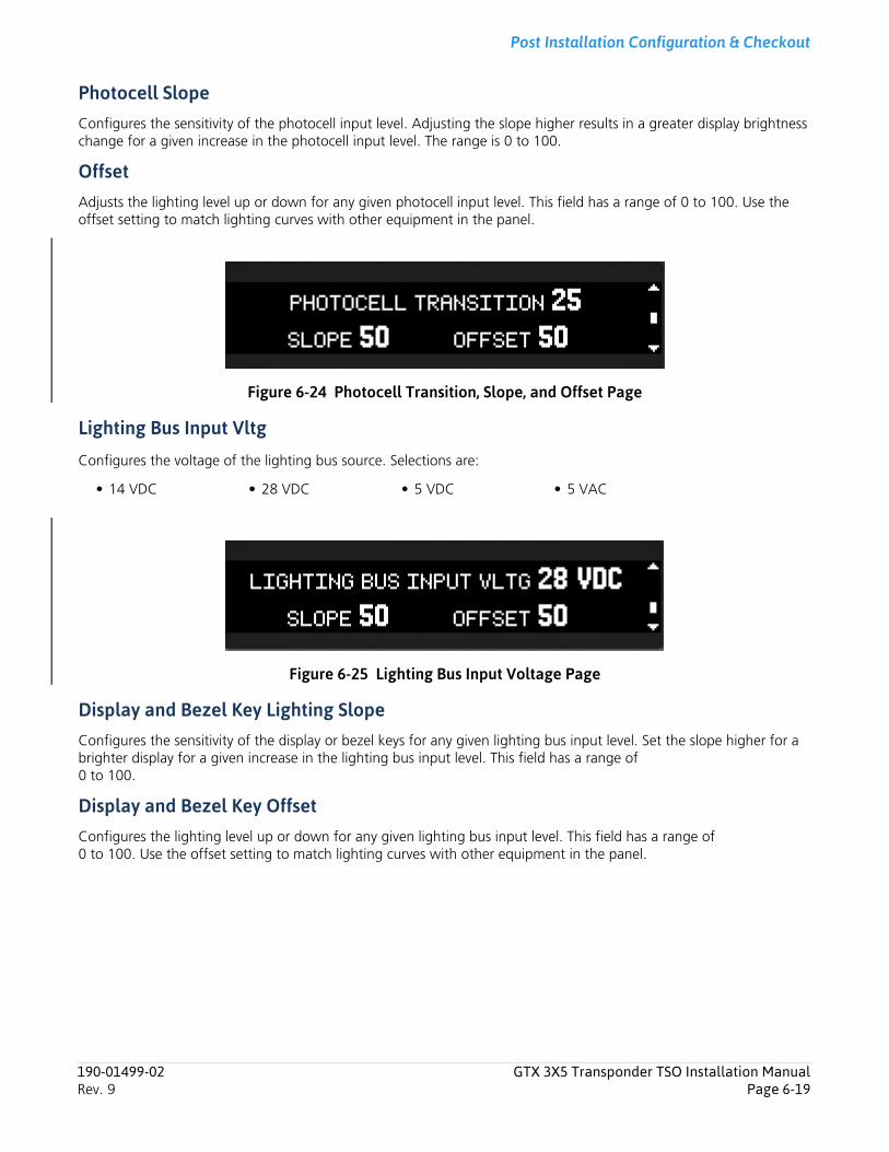
Post Installation Configuration & Checkout
Photocell SlopeConfigures the sensitivity of the photocell input level. Adjusting the slope higher results in a greater display brightness change for a given increase in the photocell input level. The range is 0 to 100.
OffsetAdjusts the lighting level up or down for any given photocell input level. This field has a range of 0 to 100. Use the offset setting to match lighting curves with other equipment in the panel.
Figure 6-24 Photocell Transition, Slope, and Offset Page
Lighting Bus Input Vltg
Configures the voltage of the lighting bus source. Selections are:
Figure 6-25 Lighting Bus Input Voltage Page
Display and Bezel Key Lighting SlopeConfigures the sensitivity of the display or bezel keys for any given lighting bus input level. Set the slope higher for a brighter display for a given increase in the lighting bus input level. This field has a range of 0 to 100.
Display and Bezel Key OffsetConfigures the lighting level up or down for any given lighting bus input level. This field has a range of 0 to 100. Use the offset setting to match lighting curves with other equipment in the panel.
• 14 VDC • 28 VDC • 5 VDC • 5 VAC
190-01499-02 GTX 3X5 Transponder TSO Installation ManualRev. 9 Page 6-19
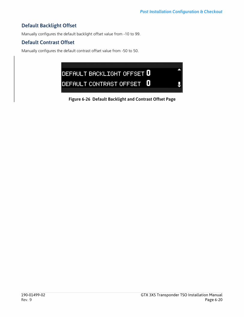
Post Installation Configuration & Checkout
Default Backlight OffsetManually configures the default backlight offset value from -10 to 99.
Default Contrast OffsetManually configures the default contrast offset value from -50 to 50.
Figure 6-26 Default Backlight and Contrast Offset Page
190-01499-02 GTX 3X5 Transponder TSO Installation ManualRev. 9 Page 6-20
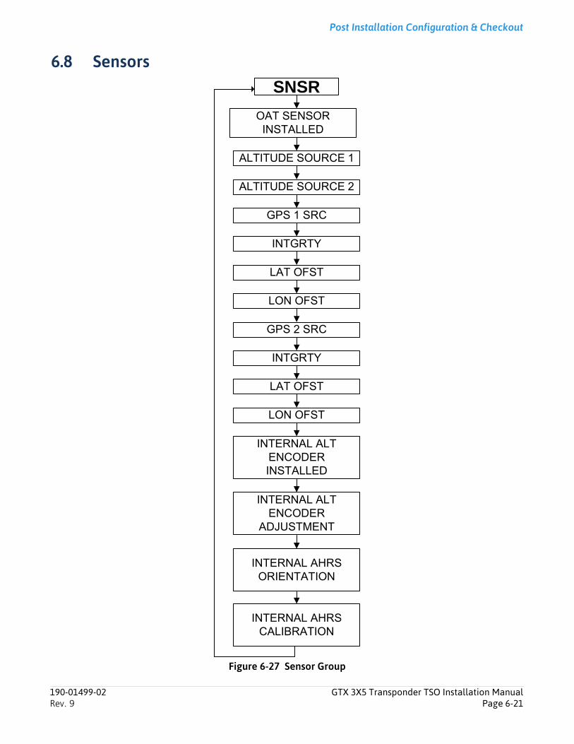
Post Installation Configuration & Checkout
6.8 Sensors
Figure 6-27 Sensor Group
SNSR
OAT SENSOR INSTALLED
ALTITUDE SOURCE 1
ALTITUDE SOURCE 2
GPS 1 SRC
INTGRTY
LAT OFST
LON OFST
GPS 2 SRC
INTGRTY
LAT OFST
LON OFST
INTERNAL ALT ENCODER INSTALLED
INTERNAL ALTENCODER
ADJUSTMENT
INTERNAL AHRS ORIENTATION
INTERNAL AHRS CALIBRATION
190-01499-02 GTX 3X5 Transponder TSO Installation ManualRev. 9 Page 6-21
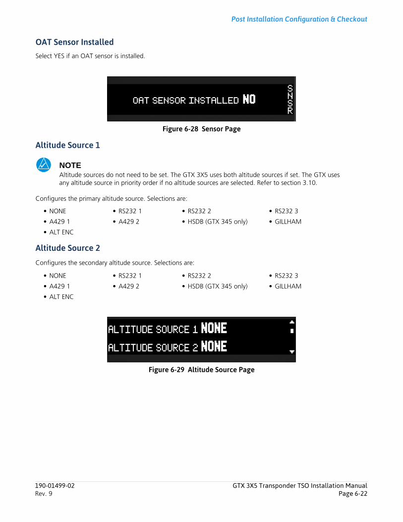
Post Installation Configuration & Checkout
OAT Sensor InstalledSelect YES if an OAT sensor is installed.
Figure 6-28 Sensor Page
Altitude Source 1
NOTEAltitude sources do not need to be set. The GTX 3X5 uses both altitude sources if set. The GTX uses any altitude source in priority order if no altitude sources are selected. Refer to section 3.10.
Configures the primary altitude source. Selections are:
Altitude Source 2
Configures the secondary altitude source. Selections are:
Figure 6-29 Altitude Source Page
• NONE • RS232 1 • RS232 2 • RS232 3
• A429 1 • A429 2 • HSDB (GTX 345 only) • GILLHAM
• ALT ENC
• NONE • RS232 1 • RS232 2 • RS232 3
• A429 1 • A429 2 • HSDB (GTX 345 only) • GILLHAM
• ALT ENC
190-01499-02 GTX 3X5 Transponder TSO Installation ManualRev. 9 Page 6-22
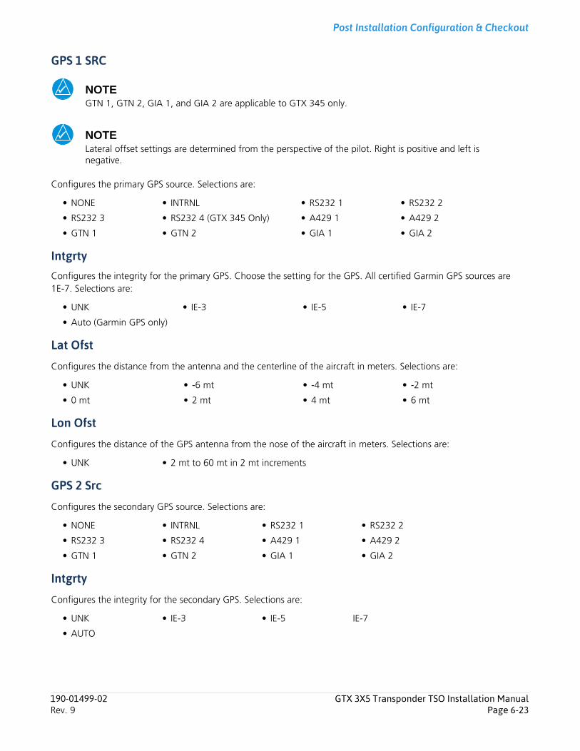
Post Installation Configuration & Checkout
GPS 1 SRC
NOTEGTN 1, GTN 2, GIA 1, and GIA 2 are applicable to GTX 345 only.
NOTELateral offset settings are determined from the perspective of the pilot. Right is positive and left is negative.
Configures the primary GPS source. Selections are:
IntgrtyConfigures the integrity for the primary GPS. Choose the setting for the GPS. All certified Garmin GPS sources are 1E-7. Selections are:
Lat Ofst
Configures the distance from the antenna and the centerline of the aircraft in meters. Selections are:
Lon Ofst
Configures the distance of the GPS antenna from the nose of the aircraft in meters. Selections are:
GPS 2 Src
Configures the secondary GPS source. Selections are:
Intgrty
Configures the integrity for the secondary GPS. Selections are:
• NONE • INTRNL • RS232 1 • RS232 2
• RS232 3 • RS232 4 (GTX 345 Only) • A429 1 • A429 2
• GTN 1 • GTN 2 • GIA 1 • GIA 2
• UNK • IE-3 • IE-5 • IE-7
• Auto (Garmin GPS only)
• UNK • -6 mt • -4 mt • -2 mt
• 0 mt • 2 mt • 4 mt • 6 mt
• UNK • 2 mt to 60 mt in 2 mt increments
• NONE • INTRNL • RS232 1 • RS232 2
• RS232 3 • RS232 4 • A429 1 • A429 2
• GTN 1 • GTN 2 • GIA 1 • GIA 2
• UNK • IE-3 • IE-5 IE-7
• AUTO
190-01499-02 GTX 3X5 Transponder TSO Installation ManualRev. 9 Page 6-23
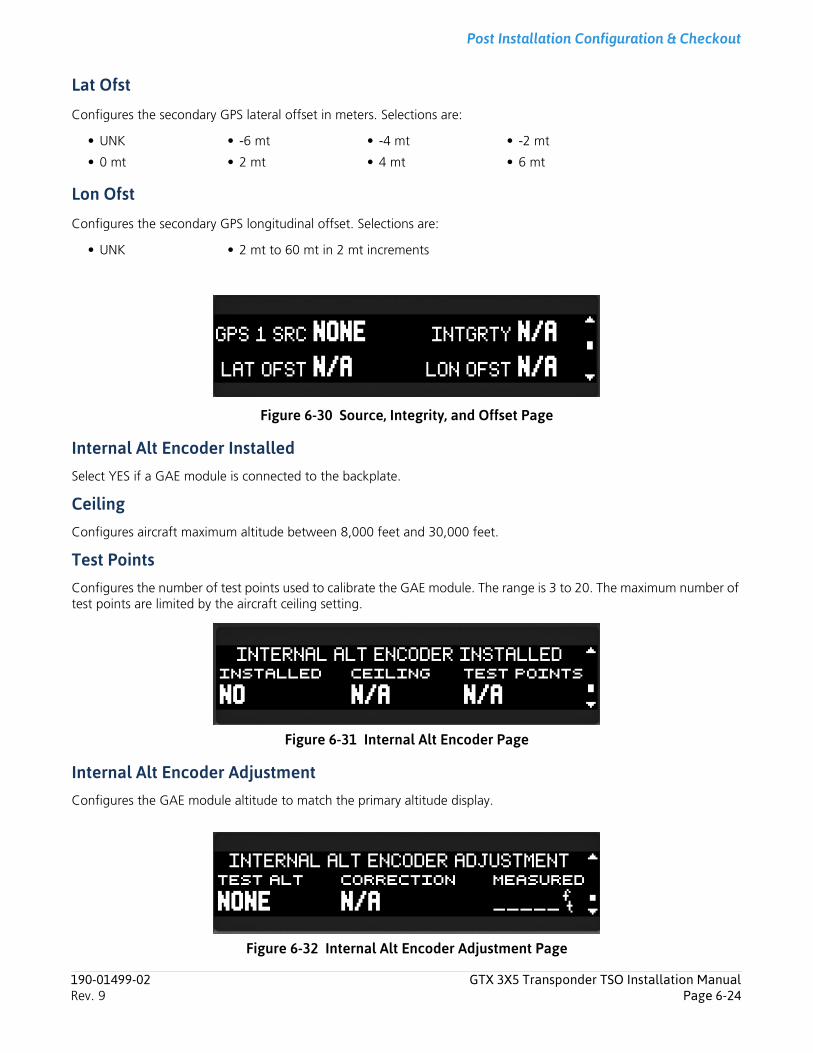
Post Installation Configuration & Checkout
Lat Ofst
Configures the secondary GPS lateral offset in meters. Selections are:
Lon Ofst
Configures the secondary GPS longitudinal offset. Selections are:
Figure 6-30 Source, Integrity, and Offset Page
Internal Alt Encoder InstalledSelect YES if a GAE module is connected to the backplate.
CeilingConfigures aircraft maximum altitude between 8,000 feet and 30,000 feet.
Test PointsConfigures the number of test points used to calibrate the GAE module. The range is 3 to 20. The maximum number of test points are limited by the aircraft ceiling setting.
Figure 6-31 Internal Alt Encoder Page
Internal Alt Encoder AdjustmentConfigures the GAE module altitude to match the primary altitude display.
Figure 6-32 Internal Alt Encoder Adjustment Page
• UNK • -6 mt • -4 mt • -2 mt
• 0 mt • 2 mt • 4 mt • 6 mt
• UNK • 2 mt to 60 mt in 2 mt increments
190-01499-02 GTX 3X5 Transponder TSO Installation ManualRev. 9 Page 6-24
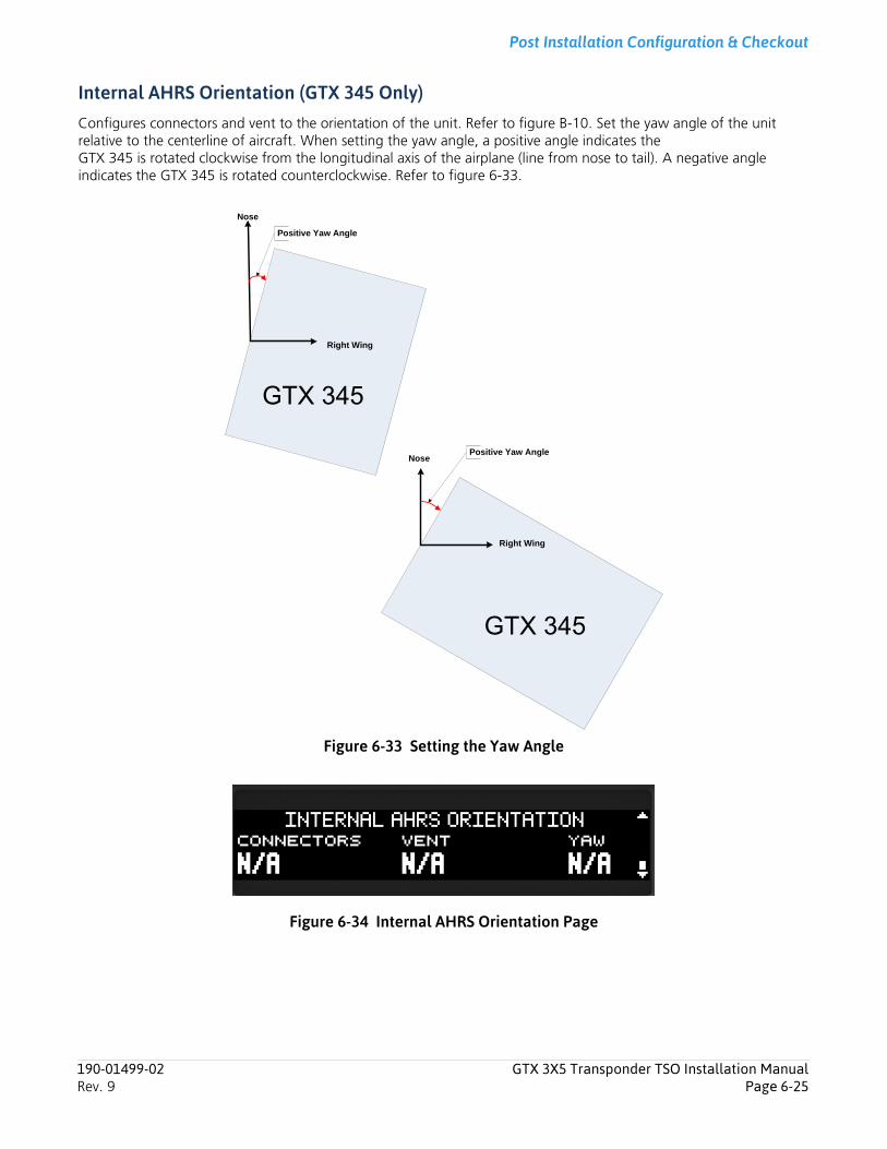
Post Installation Configuration & Checkout
Internal AHRS Orientation (GTX 345 Only)Configures connectors and vent to the orientation of the unit. Refer to figure B-10. Set the yaw angle of the unit relative to the centerline of aircraft. When setting the yaw angle, a positive angle indicates the GTX 345 is rotated clockwise from the longitudinal axis of the airplane (line from nose to tail). A negative angle indicates the GTX 345 is rotated counterclockwise. Refer to figure 6-33.
Figure 6-33 Setting the Yaw Angle
Figure 6-34 Internal AHRS Orientation Page
Nose
Right Wing
Positive Yaw Angle
Nose
Right Wing
Positive Yaw Angle
GTX 345
GTX 345
190-01499-02 GTX 3X5 Transponder TSO Installation ManualRev. 9 Page 6-25
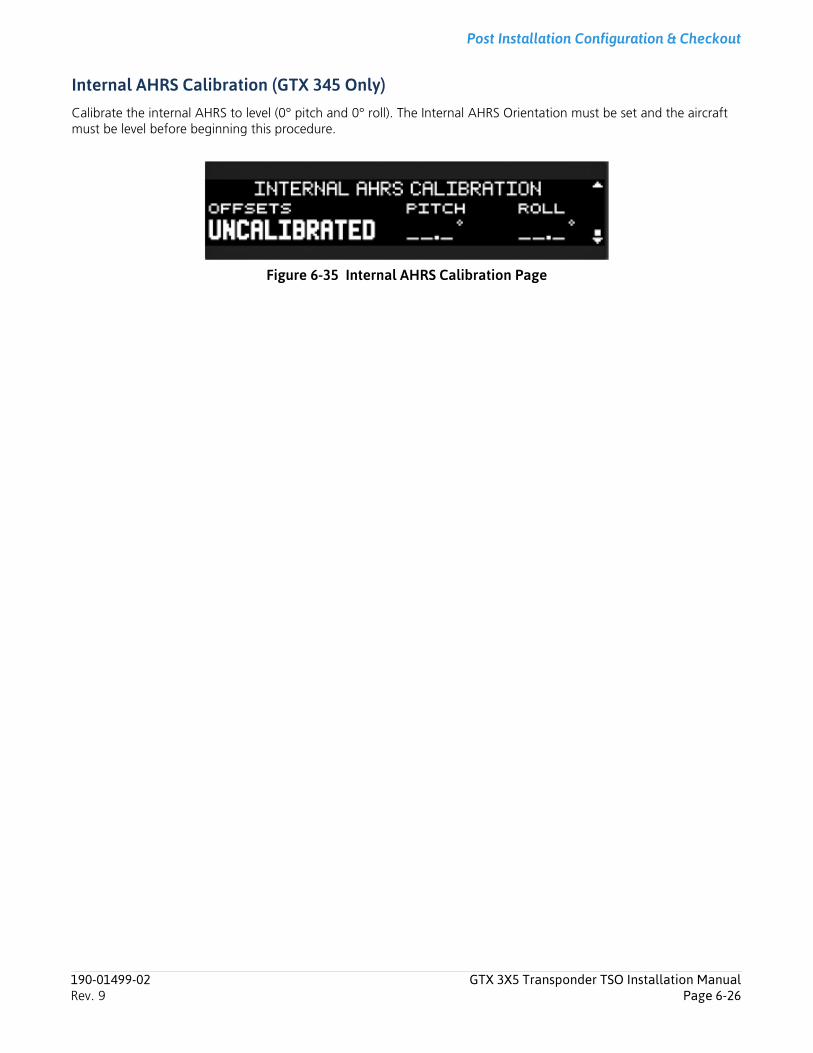
Post Installation Configuration & Checkout
Internal AHRS Calibration (GTX 345 Only)Calibrate the internal AHRS to level (0° pitch and 0° roll). The Internal AHRS Orientation must be set and the aircraft must be level before beginning this procedure.
Figure 6-35 Internal AHRS Calibration Page
190-01499-02 GTX 3X5 Transponder TSO Installation ManualRev. 9 Page 6-26

Post Installation Configuration & Checkout
6.9 ADSBNOTEBoth 1090ES and UAT In settings can be set to YES when a portable ADS-B In receiver system, such as a GDL 39, is installed. It is not necessary to install a certified ADS-B In system.
NOTEThe GDL format must be configured to modify UAT OUT RMT CONTROL.
Figure 6-36 ADS-B Group
ADSB
1090ES IN CAPABLE
UAT IN CAPABLE
AIRCRAFT WIDTH
AIRCRAFT LENGTH
ACFT MAX A/S
ACFT CATGRY
UAT OUT RMT CONTROL
1090ES OUT CONTROL
ADS-B IN PROCESSING
ALLOW PILOT TO EDIT FLT ID
ADDRESS
AIRCRAFT TAIL NUMBER
FLT ID PREFIX
ACFT STALL SPEED METHOD
DEFAULT FLT ID
ACFT STALL SPEED
190-01499-02 GTX 3X5 Transponder TSO Installation ManualRev. 9 Page 6-27
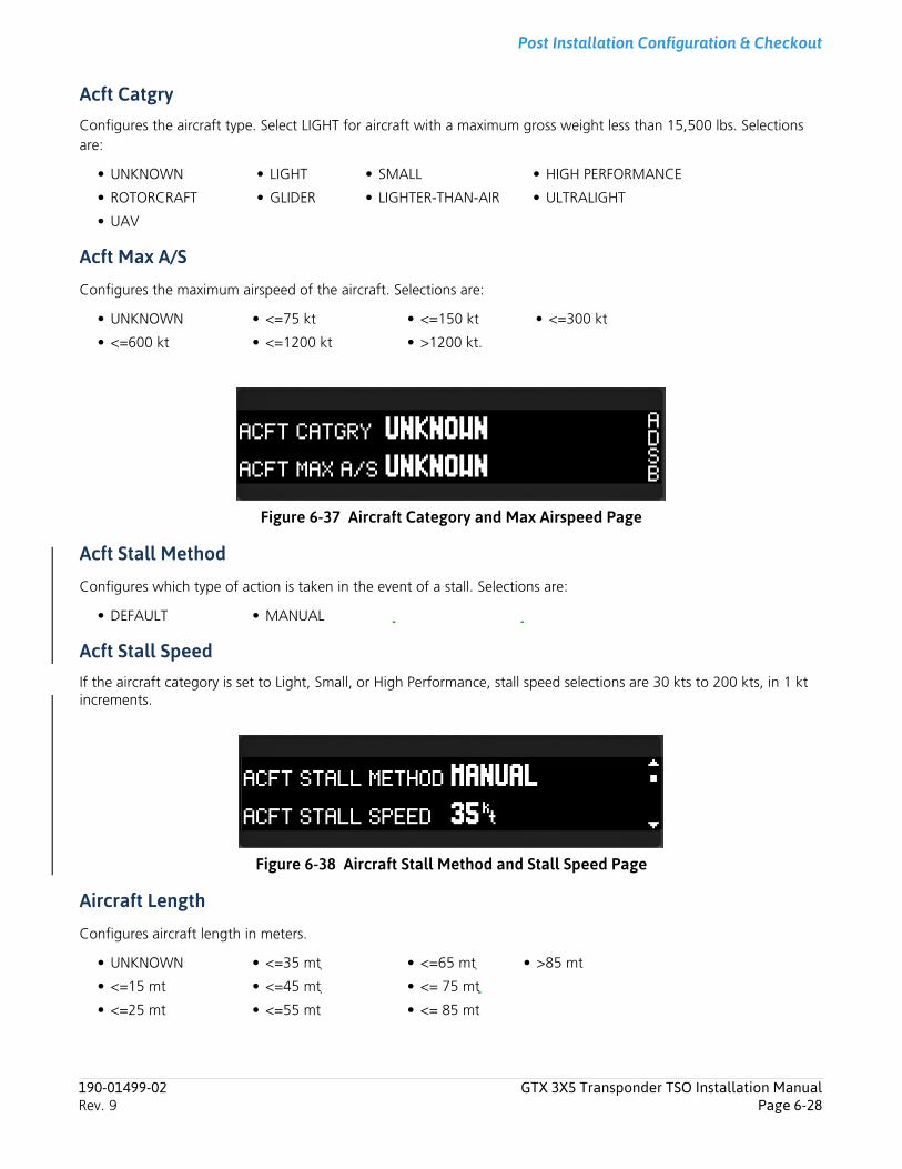
Post Installation Configuration & Checkout
Acft CatgryConfigures the aircraft type. Select LIGHT for aircraft with a maximum gross weight less than 15,500 lbs. Selections are:
Acft Max A/S
Configures the maximum airspeed of the aircraft. Selections are:
Figure 6-37 Aircraft Category and Max Airspeed Page
Acft Stall Method
Configures which type of action is taken in the event of a stall. Selections are:
Acft Stall SpeedIf the aircraft category is set to Light, Small, or High Performance, stall speed selections are 30 kts to 200 kts, in 1 kt increments.
Figure 6-38 Aircraft Stall Method and Stall Speed Page
Aircraft Length
Configures aircraft length in meters.
• UNKNOWN • LIGHT • SMALL • HIGH PERFORMANCE
• ROTORCRAFT • GLIDER • LIGHTER-THAN-AIR • ULTRALIGHT
• UAV
• UNKNOWN • <=75 kt • <=150 kt • <=300 kt
• <=600 kt • <=1200 kt • >1200 kt.
• DEFAULT • MANUAL
• UNKNOWN • <=35 mt • <=65 mt • >85 mt
• <=15 mt • <=45 mt • <= 75 mt
• <=25 mt • <=55 mt • <= 85 mt
190-01499-02 GTX 3X5 Transponder TSO Installation ManualRev. 9 Page 6-28
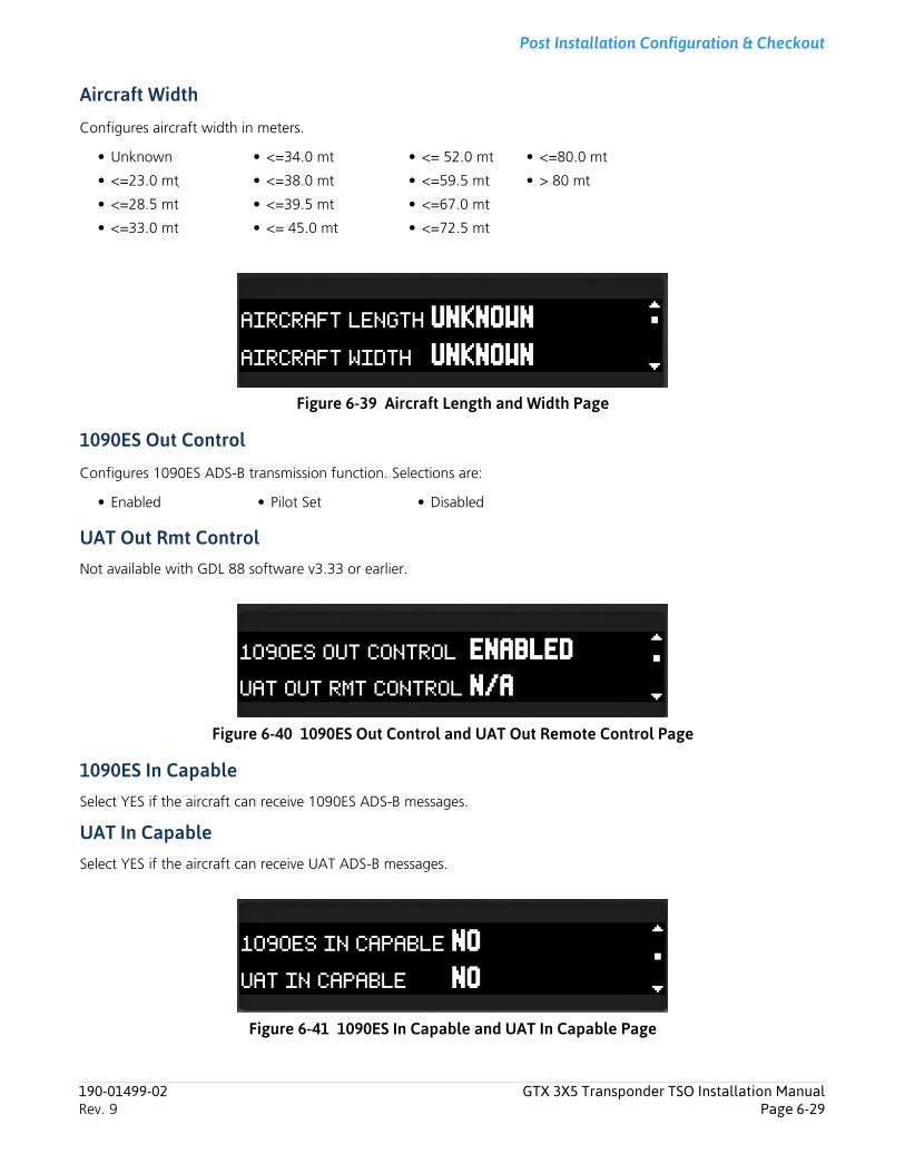
Post Installation Configuration & Checkout
Aircraft Width
Configures aircraft width in meters.
Figure 6-39 Aircraft Length and Width Page
1090ES Out Control
Configures 1090ES ADS-B transmission function. Selections are:
UAT Out Rmt ControlNot available with GDL 88 software v3.33 or earlier.
Figure 6-40 1090ES Out Control and UAT Out Remote Control Page
1090ES In CapableSelect YES if the aircraft can receive 1090ES ADS-B messages.
UAT In CapableSelect YES if the aircraft can receive UAT ADS-B messages.
Figure 6-41 1090ES In Capable and UAT In Capable Page
• Unknown • <=34.0 mt • <= 52.0 mt • <=80.0 mt
• <=23.0 mt • <=38.0 mt • <=59.5 mt • > 80 mt
• <=28.5 mt • <=39.5 mt • <=67.0 mt
• <=33.0 mt • <= 45.0 mt • <=72.5 mt
• Enabled • Pilot Set • Disabled
190-01499-02 GTX 3X5 Transponder TSO Installation ManualRev. 9 Page 6-29
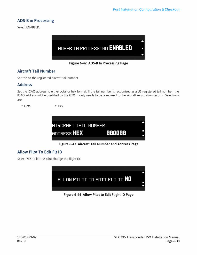
Post Installation Configuration & Checkout
ADS-B in ProcessingSelect ENABLED.
Figure 6-42 ADS-B In Processing Page
Aircraft Tail NumberSet this to the registered aircraft tail number.
AddressSet the ICAO address to either octal or hex format. If the tail number is recognized as a US registered tail number, the ICAO address will be pre-filled by the GTX. It only needs to be compared to the aircraft registration records. Selections are:
Figure 6-43 Aircraft Tail Number and Address Page
Allow Pilot To Edit Flt IDSelect YES to let the pilot change the flight ID.
Figure 6-44 Allow Pilot to Edit Flight ID Page
• Octal • Hex
190-01499-02 GTX 3X5 Transponder TSO Installation ManualRev. 9 Page 6-30
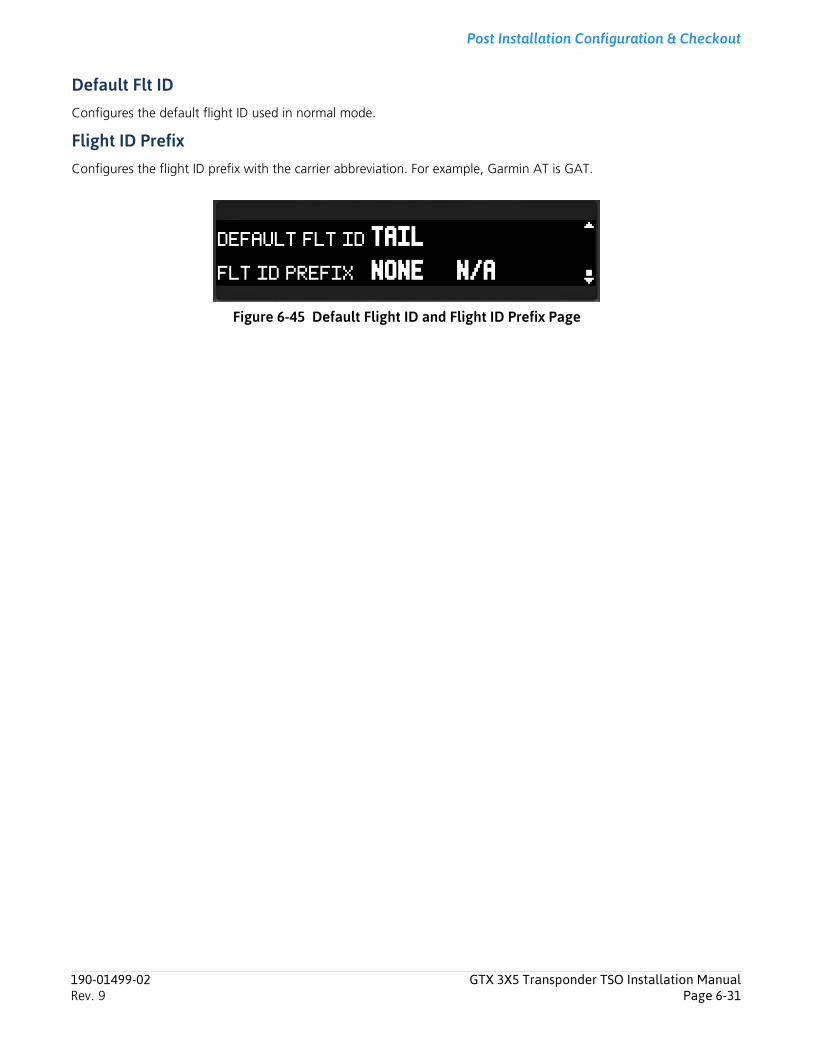
Post Installation Configuration & Checkout
Default Flt IDConfigures the default flight ID used in normal mode.
Flight ID PrefixConfigures the flight ID prefix with the carrier abbreviation. For example, Garmin AT is GAT.
Figure 6-45 Default Flight ID and Flight ID Prefix Page
190-01499-02 GTX 3X5 Transponder TSO Installation ManualRev. 9 Page 6-31
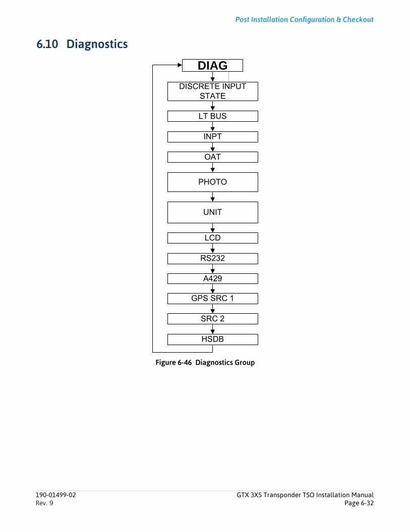
Post Installation Configuration & Checkout
6.10 Diagnostics
Figure 6-46 Diagnostics Group
DIAG
LCD
RS232
OAT
INPT
LT BUS
DISCRETE INPUT STATE
UNIT
PHOTO
A429
SRC 2
GPS SRC 1
HSDB
190-01499-02 GTX 3X5 Transponder TSO Installation ManualRev. 9 Page 6-32
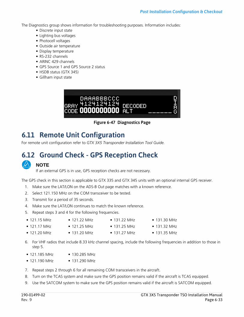
Post Installation Configuration & Checkout
The Diagnostics group shows information for troubleshooting purposes. Information includes:• Discrete input state• Lighting bus voltages• Photocell voltages• Outside air temperature• Display temperature• RS-232 channels• ARINC 429 channels• GPS Source 1 and GPS Source 2 status• HSDB status (GTX 345)• Gillham input state
Figure 6-47 Diagnostics Page
6.11 Remote Unit ConfigurationFor remote unit configuration refer to GTX 3X5 Transponder Installation Tool Guide.
6.12 Ground Check - GPS Reception CheckNOTEIf an external GPS is in use, GPS reception checks are not necessary.
The GPS check in this section is applicable to GTX 335 and GTX 345 units with an optional internal GPS receiver.
1. Make sure the LAT/LON on the ADS-B Out page matches with a known reference.
2. Select 121.150 MHz on the COM transceiver to be tested.
3. Transmit for a period of 35 seconds.
4. Make sure the LAT/LON continues to match the known reference.
5. Repeat steps 3 and 4 for the following frequencies.
6. For VHF radios that include 8.33 kHz channel spacing, include the following frequencies in addition to those in step 5.
7. Repeat steps 2 through 6 for all remaining COM transceivers in the aircraft.
8. Turn on the TCAS system and make sure the GPS position remains valid if the aircraft is TCAS equipped.
9. Use the SATCOM system to make sure the GPS position remains valid if the aircraft is SATCOM equipped.
• 121.15 MHz • 121.22 MHz • 131.22 MHz • 131.30 MHz
• 121.17 MHz • 121.25 MHz • 131.25 MHz • 131.32 MHz
• 121.20 MHz • 131.20 MHz • 131.27 MHz • 131.35 MHz
• 121.185 MHz • 130.285 MHz
• 121.190 MHz • 131.290 MHz
190-01499-02 GTX 3X5 Transponder TSO Installation ManualRev. 9 Page 6-33
Post Installation Configuration & Checkout
6.13 Ground Check - TransponderFAR 91.413 transponder checks require the GTX to reply to different types of interrogations. The GTX 3X5 only replies to Mode S/A/C All Calls when airborne.
To simulate a temporary airborne state, place the GTX 3X5 in Ground Test mode. Ground Test mode overrides the air/ground logic to transmit as if the GTX is airborne. This mode has a duration of one power cycle.
To enable Ground Test mode, press and hold CRSR while applying power to the unit. Ground Test mode can be enabled by the GTX 3X5 Install Tool on the State page.
FAR 91.413 provides guidance for the transponder check.
6.14 Software Installation ProcedureFor software installation procedures refer to GTX 3X5 Transponder Installation Tool Guide.
190-01499-02 GTX 3X5 Transponder TSO Installation ManualRev. 9 Page 6-34
Continued Airworthiness
190-01499-02 GTX 3X5 Transponder TSO Installation ManualRev. 9 Page 7-1
7 Continued AirworthinessOther than for regulatory periodic functional checks, maintenance of the GTX 3X5 is “on condition” only. Periodic maintenance of the GTX 3X5 is not required.

Data Formats
Appendix A Data FormatsA.1 RS-232 Air Data Input Format ........................................................................................................................A-1
A.1.1 Electrical Interface ...................................................................................................................................A-1A.1.2 Altitude Format 1 Sentence.....................................................................................................................A-1A.1.3 Altitude Format 3 Sentence.....................................................................................................................A-1A.1.4 Airdata Format 1 Sentence......................................................................................................................A-2
A.2 ARINC 429 Input Formats ..............................................................................................................................A-5A.3 ARINC 429 Output Formats ...........................................................................................................................A-9
A.1 RS-232 Air Data Input FormatA.1.1 Electrical InterfaceThe input signals are compatible with RS-232C. Data input at 9600 baud with a word length of 8 bits, one stop bit, and no parity. One message is received per second.
A.1.2 Altitude Format 1 SentenceThe GTX 3X5 is capable of receiving the following 10-byte message from the altitude serializer.
ALT <sp>12345<CR>Where:
ALT ASCII characters<sp> space (0x20)12345 altitude in feet<CR> carriage return (0x0D)
A.1.3 Altitude Format 3 SentenceThe GTX 3X5 is capable of receiving the following 17-byte message from GAE modules, altitude serializers, and altitude converters.
RMS<sp><+/->12345T<+/->12ul<CR>Where:
RMS ASCII characters<sp> space (0x20)<+/-> sign indicator (0x2B[+] or 0x2D[-])12345 altitude in feetT ASCII character<+/-> sign indicator12 sensor temperatureul checksum of bytes 1 through 14 in hex ASCII (i.e., FA)<CR> carriage return (0x0D)
NOTEChecksum is calculated by adding each byte in the message (1 through 14).
190-01499-02 GTX 3X5 Transponder TSO Installation ManualRev. 9 Page A-1

Data Formats
A.1.4 Airdata Format 1 SentenceThe GTX 3X5 is capable of receiving the following message strings from the air data computer.
SHADIN Z FORMAT<STX>ZA012<CR><LF> ZA (ASCII characters); 012 represents indicated air speed (knots)ZB345<CR><LF> ZB (ASCII characters); 345 represents true air speed (knots)ZC678<CR><LF> ZC (ASCII characters); 678 represents mach speed (thousandths)ZD<+/->9012<CR><LF> ZD (ASCII characters); sign; 9012 represents pressure altitude (tens of feet)ZE<+/->3456<CR><LF> ZE (ASCII characters); sign; 3456 represents density altitude (tens of feet)ZF<+/->78<CR><LF> ZF (ASCII characters); sign; 78 represents outside air temperature (Celsius)ZG<+/->90<CR><LF> ZG (ASCII characters); sign; 90 represents true air temperature (Celsius)ZL234<CR><LF> ZL (ASCII characters); 234 represents heading (degrees from north)ZQ345<CR><LF> ZQ (ASCII characters); 345 represents error log/reason indicatorZR678<CR><LF> ZR (ASCII characters); 678 represents checksum<ETX>
Where: <STX> start-transmit character (0x02)<CR> carriage-return character (0x0D)<LF> line-feed character (0x0A)<+/-> sign indicator (0x2B[+] or 0x2D[-])<ETX> end-transmit character (0x03)
NOTEChecksum is calculated by adding each byte in the message (including all characters from <STX> up to and including the error log/reason indicator), such that carries are discarded to give a one byte result. The ASCII-coded decimal representation of that byte is given, ranging from 0 (0x30, 0x30, 0x30) to 255 (0x32, 0x35, 0x35).
190-01499-02 GTX 3X5 Transponder TSO Installation ManualRev. 9 Page A-2
Data Formats
SHADIN G FORMAT<STX>GA012<CR><LF> GA (ASCII characters); 012 represents indicated air speed (knots)GB345<CR><LF> GB (ASCII characters); 345 represents true air speed (knots)GC678<CR><LF> GC (ASCII characters); 678 represents Mach speed (thousandths)GD<+/->9012<CR><LF> GD (ASCII characters); sign; 9012 represents pressure altitude (tens of feet)GE<+/->3456<CR><LF> GE (ASCII characters); sign; 3456 represents density altitude (tens of feet)GF<+/->78<CR><LF> GF (ASCII characters); sign; 78 represents outside air temperature (Celsius)GG<+/->90<CR><LF> GG (ASCII characters); sign; 90 represents true air temperature (Celsius)GK<+/->901<CR><LF> GK (ASCII characters); sign; 901 represents vertical speed (tens of ft/minute)GL234<CR><LF> GL (ASCII characters); 234 represents heading (degrees from north)GP89012<CR><LF> GP (ASCII characters); 89012 represents fuel used, left (or Single) (tenths gallons)GR6789.0<CR><LF> GR (ASCII characters); 6789.0 represents fuel remaining (gallons) [1]Ga<+/->1234<CR><LF> Ga (ASCII characters); sign; 12.34 represents barometric corrected altitude (tens of feet)Gb56.78<CR><LF> Gb (ASCII characters); 56.78 represents current barometric pressure setting (inches Hg)G*901<CR><LF> G* (ASCII characters); 901 represents checksum<ETX>Where: <STX> start-transmit character (0x02)<CR> carriage-return character (0x0D)<LF> line-feed character (0x0A)<+/-> sign indicator (0x2B[+] or 0x2D[-])<ETX> end-transmit character (0x03)
[1] Not available from Airdata Computer
NOTEChecksum is calculated by adding each byte in the message (including all characters from <STX> up to and including the error log/reason indicator), such that carries are discarded to give a one byte result. The ASCII-coded decimal representation of that byte is given, ranging from 0 (0x30, 0x30, 0x30) to 255 (0x32, 0x35, 0x35).
190-01499-02 GTX 3X5 Transponder TSO Installation ManualRev. 9 Page A-3
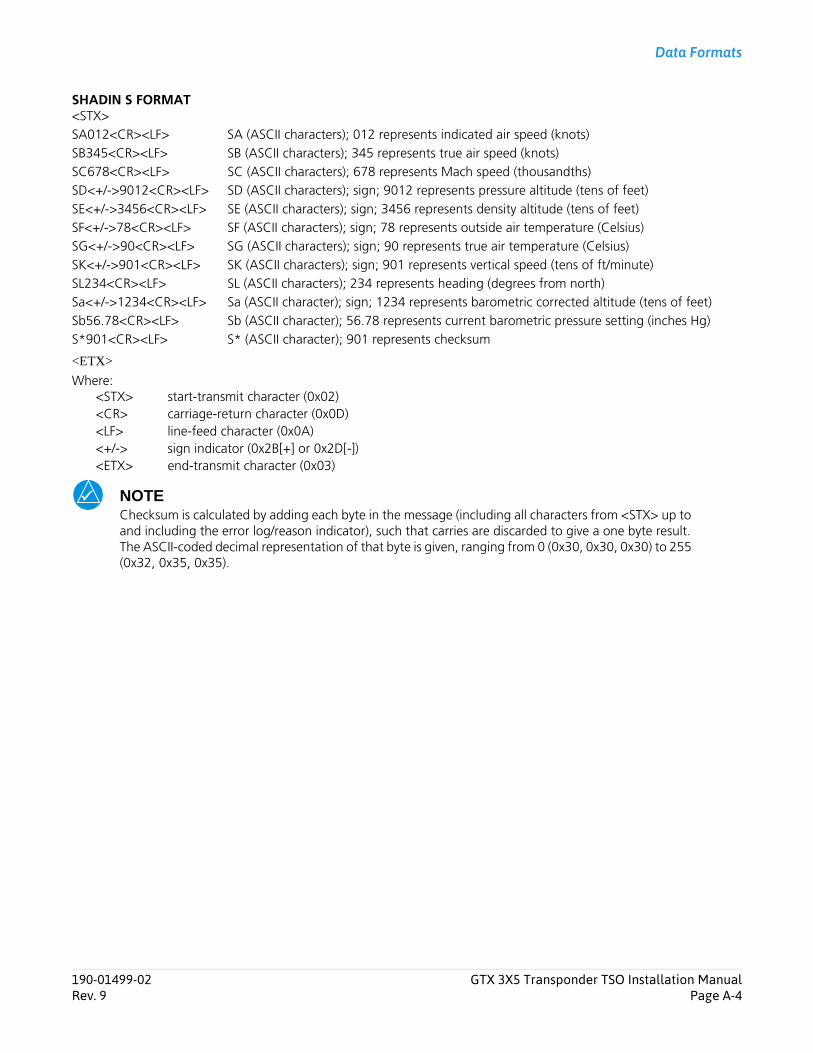
Data Formats
SHADIN S FORMAT<STX>SA012<CR><LF> SA (ASCII characters); 012 represents indicated air speed (knots)SB345<CR><LF> SB (ASCII characters); 345 represents true air speed (knots)SC678<CR><LF> SC (ASCII characters); 678 represents Mach speed (thousandths)SD<+/->9012<CR><LF> SD (ASCII characters); sign; 9012 represents pressure altitude (tens of feet)SE<+/->3456<CR><LF> SE (ASCII characters); sign; 3456 represents density altitude (tens of feet)SF<+/->78<CR><LF> SF (ASCII characters); sign; 78 represents outside air temperature (Celsius)SG<+/->90<CR><LF> SG (ASCII characters); sign; 90 represents true air temperature (Celsius)SK<+/->901<CR><LF> SK (ASCII characters); sign; 901 represents vertical speed (tens of ft/minute)SL234<CR><LF> SL (ASCII characters); 234 represents heading (degrees from north)Sa<+/->1234<CR><LF> Sa (ASCII character); sign; 1234 represents barometric corrected altitude (tens of feet)Sb56.78<CR><LF> Sb (ASCII character); 56.78 represents current barometric pressure setting (inches Hg)S*901<CR><LF> S* (ASCII character); 901 represents checksum
<ETX>
Where: <STX> start-transmit character (0x02)<CR> carriage-return character (0x0D)<LF> line-feed character (0x0A)<+/-> sign indicator (0x2B[+] or 0x2D[-])<ETX> end-transmit character (0x03)
NOTEChecksum is calculated by adding each byte in the message (including all characters from <STX> up to and including the error log/reason indicator), such that carries are discarded to give a one byte result. The ASCII-coded decimal representation of that byte is given, ranging from 0 (0x30, 0x30, 0x30) to 255 (0x32, 0x35, 0x35).
190-01499-02 GTX 3X5 Transponder TSO Installation ManualRev. 9 Page A-4
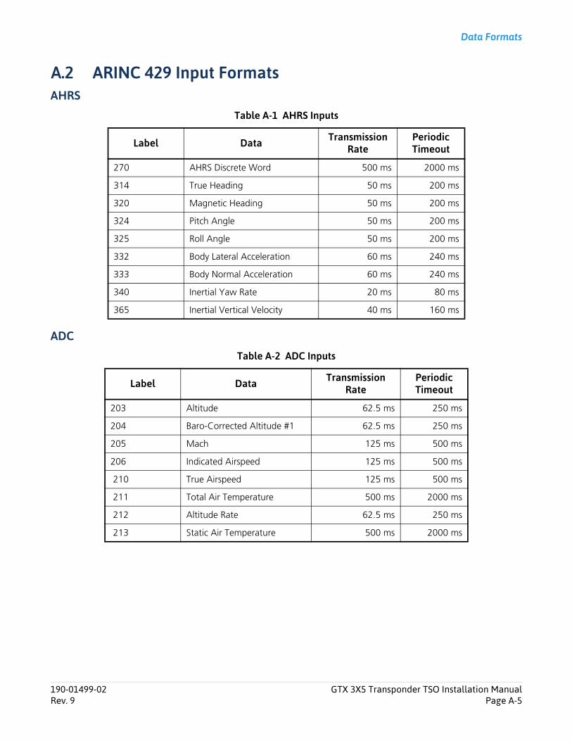
Data Formats
A.2 ARINC 429 Input FormatsAHRS
Table A-1 AHRS Inputs
ADC
Table A-2 ADC Inputs
Label Data Transmission Rate
Periodic Timeout
270 AHRS Discrete Word 500 ms 2000 ms
314 True Heading 50 ms 200 ms
320 Magnetic Heading 50 ms 200 ms
324 Pitch Angle 50 ms 200 ms
325 Roll Angle 50 ms 200 ms
332 Body Lateral Acceleration 60 ms 240 ms
333 Body Normal Acceleration 60 ms 240 ms
340 Inertial Yaw Rate 20 ms 80 ms
365 Inertial Vertical Velocity 40 ms 160 ms
Label Data Transmission Rate
Periodic Timeout
203 Altitude 62.5 ms 250 ms
204 Baro-Corrected Altitude #1 62.5 ms 250 ms
205 Mach 125 ms 500 ms
206 Indicated Airspeed 125 ms 500 ms
210 True Airspeed 125 ms 500 ms
211 Total Air Temperature 500 ms 2000 ms
212 Altitude Rate 62.5 ms 250 ms
213 Static Air Temperature 500 ms 2000 ms
190-01499-02 GTX 3X5 Transponder TSO Installation ManualRev. 9 Page A-5

Data Formats
ARINC 743A
Table A-3 ARINC 743A Inputs
Label Data Transmission Rate Periodic Timeouts
76 GNSS Altitude 200 ms 2000 ms
101 HDOP 200 ms 2000 ms
102 VDOP 200 ms 2000 ms
103 GNSS Track Angle 200 ms 2000 ms
110 GNSS Latitude 200 ms 2000 ms
111 GNSS Longitude 200 ms 2000 ms
112 GNSS Ground Speed 200 ms 2000 ms
120 GNSS Latitude Fine 200 ms 2000 ms
121 GNSS Longitude Fine 200 ms 2000 ms
130 Horizontal Protection Limit 200 ms 2000 ms
133 Vertical Protection Limit 200 ms 2000 ms
136 Vertical Figure of Merit 200 ms 2000 ms
140 UTC Fine 200 ms 2000 ms
141 UTC Fine Fractions 200 ms 2000 ms
142 Vertical Velocity Figure of Merit 200 ms 2000 ms
145 Horizontal Velocity Figure of Merit 200 ms 2000 ms
150 UTC 200 ms 2000 ms
165 Vertical Velocity 200 ms 2000 ms
166 North/South Velocity 200 ms 2000 ms
174 East/West Velocity 200 ms 2000 ms
247 Horizontal Figure of Merit 200 ms 2000 ms
260 Date 200 ms 2000 ms
273 GNSS Sensor Status 200 ms 2000 ms
370 GNSS Height 200 ms 2000 ms
190-01499-02 GTX 3X5 Transponder TSO Installation ManualRev. 9 Page A-6
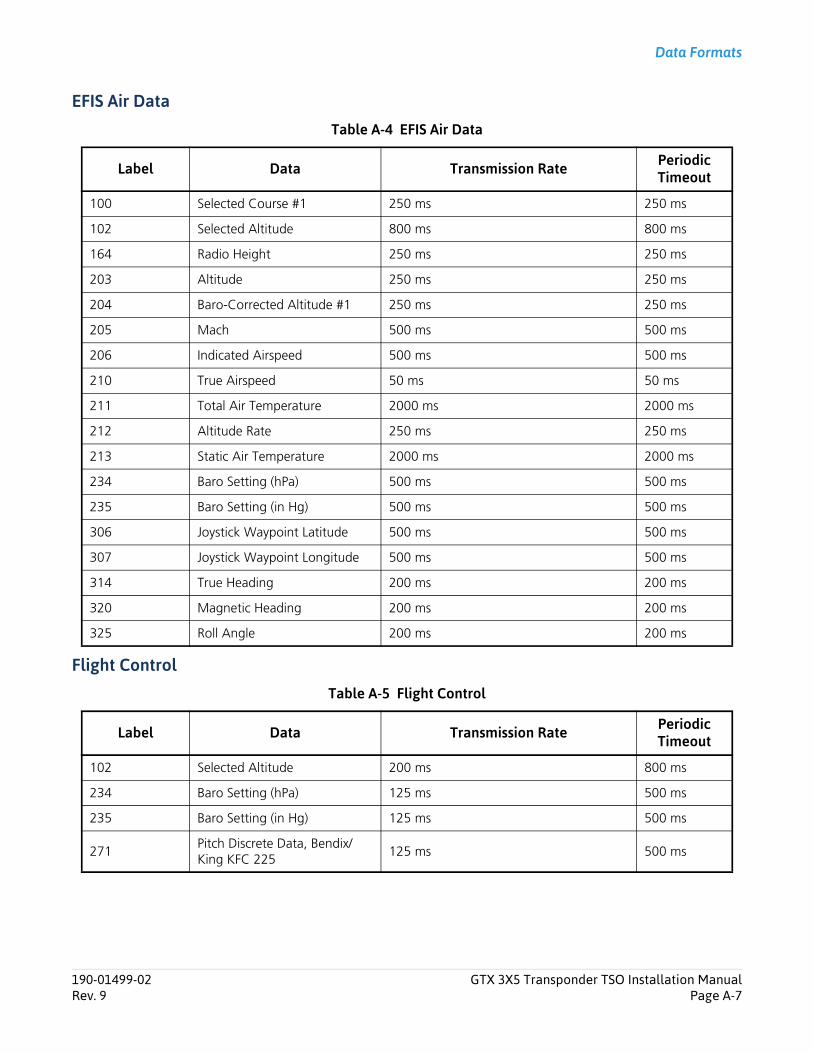
Data Formats
EFIS Air Data
Table A-4 EFIS Air Data
Flight Control
Table A-5 Flight Control
Label Data Transmission Rate Periodic Timeout
100 Selected Course #1 250 ms 250 ms
102 Selected Altitude 800 ms 800 ms
164 Radio Height 250 ms 250 ms
203 Altitude 250 ms 250 ms
204 Baro-Corrected Altitude #1 250 ms 250 ms
205 Mach 500 ms 500 ms
206 Indicated Airspeed 500 ms 500 ms
210 True Airspeed 50 ms 50 ms
211 Total Air Temperature 2000 ms 2000 ms
212 Altitude Rate 250 ms 250 ms
213 Static Air Temperature 2000 ms 2000 ms
234 Baro Setting (hPa) 500 ms 500 ms
235 Baro Setting (in Hg) 500 ms 500 ms
306 Joystick Waypoint Latitude 500 ms 500 ms
307 Joystick Waypoint Longitude 500 ms 500 ms
314 True Heading 200 ms 200 ms
320 Magnetic Heading 200 ms 200 ms
325 Roll Angle 200 ms 200 ms
Label Data Transmission Rate Periodic Timeout
102 Selected Altitude 200 ms 800 ms
234 Baro Setting (hPa) 125 ms 500 ms
235 Baro Setting (in Hg) 125 ms 500 ms
271Pitch Discrete Data, Bendix/King KFC 225
125 ms 500 ms
190-01499-02 GTX 3X5 Transponder TSO Installation ManualRev. 9 Page A-7
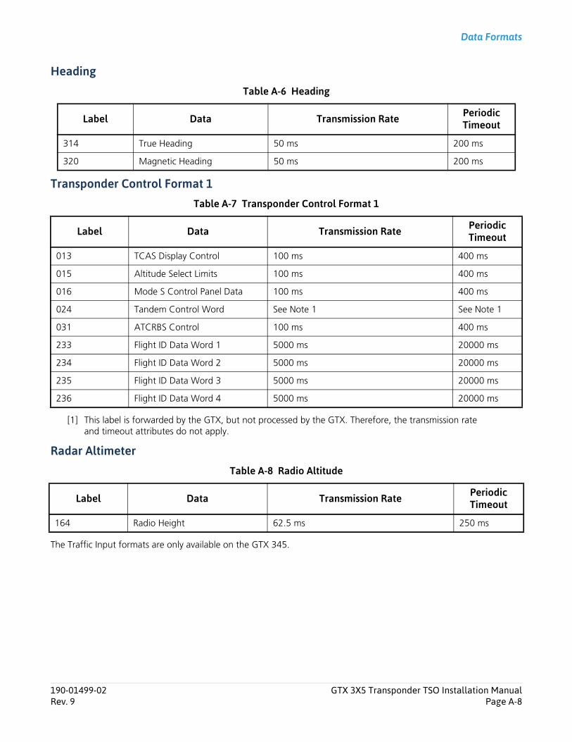
Data Formats
Heading
Table A-6 Heading
Transponder Control Format 1
Table A-7 Transponder Control Format 1
[1] This label is forwarded by the GTX, but not processed by the GTX. Therefore, the transmission rate and timeout attributes do not apply.
Radar Altimeter
Table A-8 Radio Altitude
The Traffic Input formats are only available on the GTX 345.
Label Data Transmission Rate Periodic Timeout
314 True Heading 50 ms 200 ms
320 Magnetic Heading 50 ms 200 ms
Label Data Transmission Rate Periodic Timeout
013 TCAS Display Control 100 ms 400 ms
015 Altitude Select Limits 100 ms 400 ms
016 Mode S Control Panel Data 100 ms 400 ms
024 Tandem Control Word See Note 1 See Note 1
031 ATCRBS Control 100 ms 400 ms
233 Flight ID Data Word 1 5000 ms 20000 ms
234 Flight ID Data Word 2 5000 ms 20000 ms
235 Flight ID Data Word 3 5000 ms 20000 ms
236 Flight ID Data Word 4 5000 ms 20000 ms
Label Data Transmission Rate Periodic Timeout
164 Radio Height 62.5 ms 250 ms
190-01499-02 GTX 3X5 Transponder TSO Installation ManualRev. 9 Page A-8
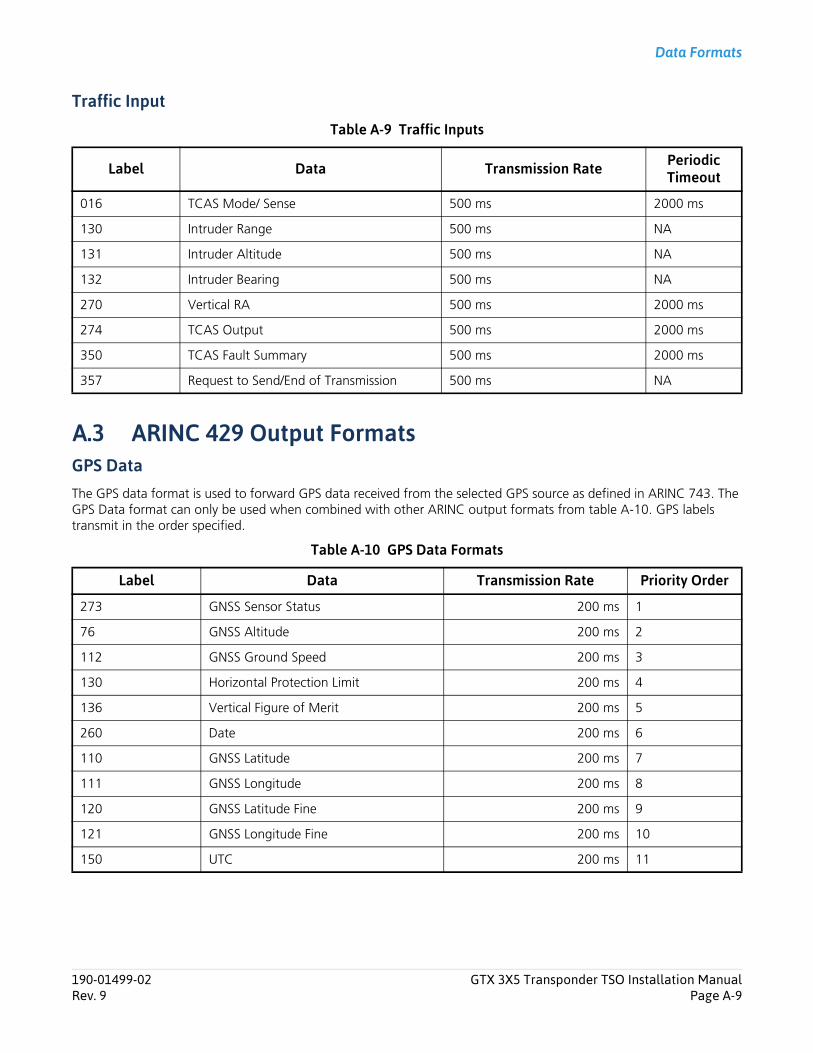
Data Formats
Traffic Input
Table A-9 Traffic Inputs
A.3 ARINC 429 Output FormatsGPS DataThe GPS data format is used to forward GPS data received from the selected GPS source as defined in ARINC 743. The GPS Data format can only be used when combined with other ARINC output formats from table A-10. GPS labels transmit in the order specified.
Table A-10 GPS Data Formats
Label Data Transmission Rate Periodic Timeout
016 TCAS Mode/ Sense 500 ms 2000 ms
130 Intruder Range 500 ms NA
131 Intruder Altitude 500 ms NA
132 Intruder Bearing 500 ms NA
270 Vertical RA 500 ms 2000 ms
274 TCAS Output 500 ms 2000 ms
350 TCAS Fault Summary 500 ms 2000 ms
357 Request to Send/End of Transmission 500 ms NA
Label Data Transmission Rate Priority Order
273 GNSS Sensor Status 200 ms 1
76 GNSS Altitude 200 ms 2
112 GNSS Ground Speed 200 ms 3
130 Horizontal Protection Limit 200 ms 4
136 Vertical Figure of Merit 200 ms 5
260 Date 200 ms 6
110 GNSS Latitude 200 ms 7
111 GNSS Longitude 200 ms 8
120 GNSS Latitude Fine 200 ms 9
121 GNSS Longitude Fine 200 ms 10
150 UTC 200 ms 11
190-01499-02 GTX 3X5 Transponder TSO Installation ManualRev. 9 Page A-9
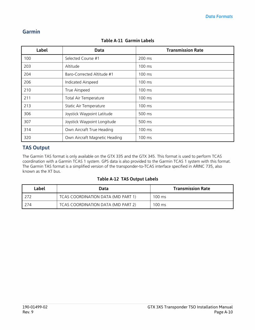
Data Formats
Garmin
Table A-11 Garmin Labels
TAS OutputThe Garmin TAS format is only available on the GTX 335 and the GTX 345. This format is used to perform TCAS coordination with a Garmin TCAS 1 system. GPS data is also provided to the Garmin TCAS 1 system with this format. The Garmin TAS format is a simplified version of the transponder-to-TCAS interface specified in ARINC 735, also known as the XT bus.
Table A-12 TAS Output Labels
Label Data Transmission Rate
100 Selected Course #1 200 ms
203 Altitude 100 ms
204 Baro-Corrected Altitude #1 100 ms
206 Indicated Airspeed 100 ms
210 True Airspeed 100 ms
211 Total Air Temperature 100 ms
213 Static Air Temperature 100 ms
306 Joystick Waypoint Latitude 500 ms
307 Joystick Waypoint Longitude 500 ms
314 Own Aircraft True Heading 100 ms
320 Own Aircraft Magnetic Heading 100 ms
Label Data Transmission Rate
272 TCAS COORDINATION DATA (MID PART 1) 100 ms
274 TCAS COORDINATION DATA (MID PART 2) 100 ms
190-01499-02 GTX 3X5 Transponder TSO Installation ManualRev. 9 Page A-10
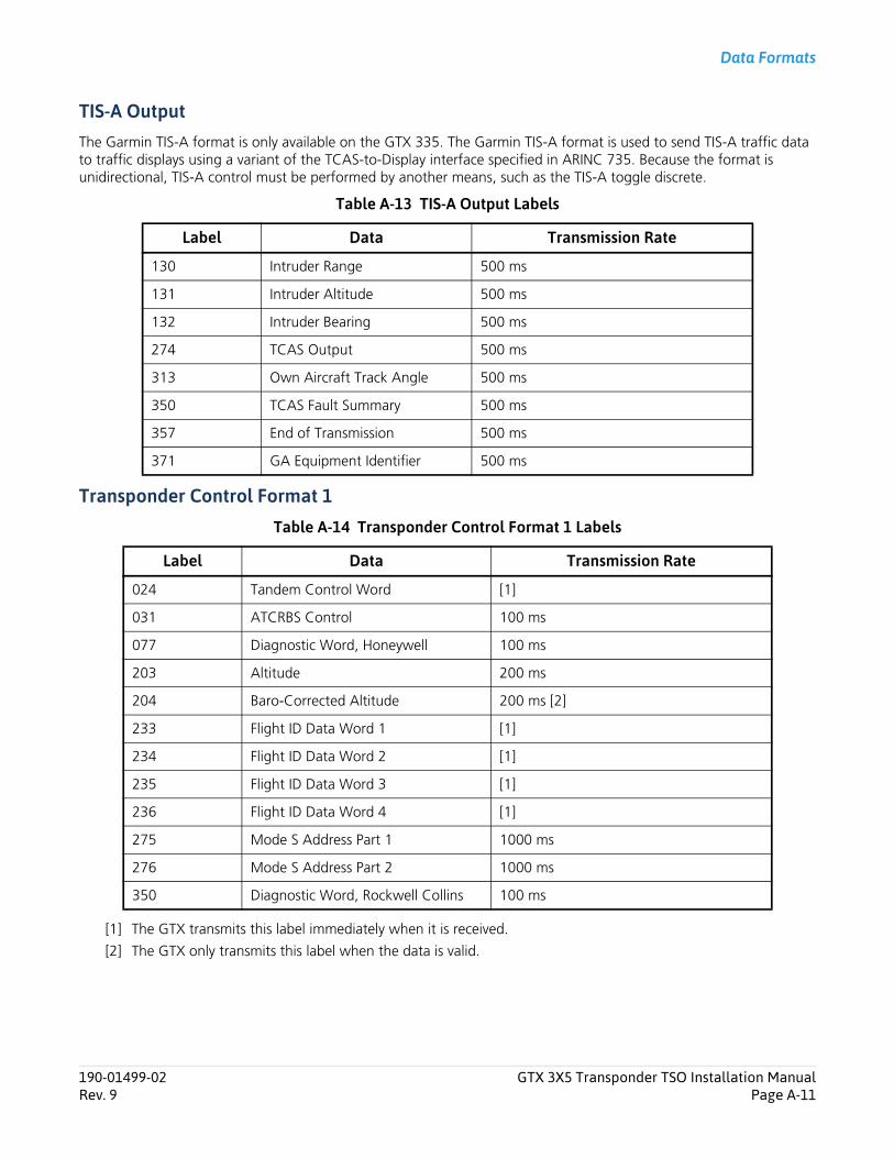
Data Formats
TIS-A OutputThe Garmin TIS-A format is only available on the GTX 335. The Garmin TIS-A format is used to send TIS-A traffic data to traffic displays using a variant of the TCAS-to-Display interface specified in ARINC 735. Because the format is unidirectional, TIS-A control must be performed by another means, such as the TIS-A toggle discrete.
Table A-13 TIS-A Output Labels
Transponder Control Format 1
Table A-14 Transponder Control Format 1 Labels
[1] The GTX transmits this label immediately when it is received.
[2] The GTX only transmits this label when the data is valid.
Label Data Transmission Rate
130 Intruder Range 500 ms
131 Intruder Altitude 500 ms
132 Intruder Bearing 500 ms
274 TCAS Output 500 ms
313 Own Aircraft Track Angle 500 ms
350 TCAS Fault Summary 500 ms
357 End of Transmission 500 ms
371 GA Equipment Identifier 500 ms
Label Data Transmission Rate
024 Tandem Control Word [1]
031 ATCRBS Control 100 ms
077 Diagnostic Word, Honeywell 100 ms
203 Altitude 200 ms
204 Baro-Corrected Altitude 200 ms [2]
233 Flight ID Data Word 1 [1]
234 Flight ID Data Word 2 [1]
235 Flight ID Data Word 3 [1]
236 Flight ID Data Word 4 [1]
275 Mode S Address Part 1 1000 ms
276 Mode S Address Part 2 1000 ms
350 Diagnostic Word, Rockwell Collins 100 ms
190-01499-02 GTX 3X5 Transponder TSO Installation ManualRev. 9 Page A-11

Data Formats
TrafficThe Traffic Output is only available on the GTX 345. The traffic output format is used to send consolidated ADS-B and TCAS traffic data to a traffic display using a variant of the TCAS-to-display interface specified in ARINC 735.
Table A-15 Traffic Labels
Label Data Transmission Rate
130 Intruder Range 500 ms
131 Intruder Altitude 500 ms
132 Intruder Bearing 500 ms
203 Own Aircraft Pressure Altitude 500 ms
313 Own Aircraft True Hack 500 ms
314 Own Aircraft True Heading 500 ms
353 ADS-B Alerts and Status 500 ms
354 TAS/TCAS/TCAD Status 500 ms
357 Request to Send 500 ms
357 End of Transmission 500 ms
190-01499-02 GTX 3X5 Transponder TSO Installation ManualRev. 9 Page A-12
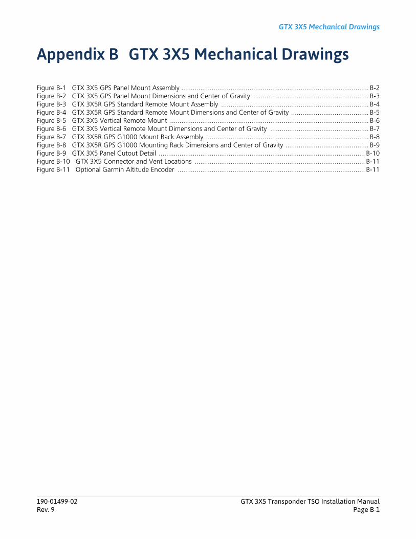
GTX 3X5 Mechanical Drawings
Appendix B GTX 3X5 Mechanical Drawings
Figure B-1 GTX 3X5 GPS Panel Mount Assembly ................................................................................................... B-2Figure B-2 GTX 3X5 GPS Panel Mount Dimensions and Center of Gravity ............................................................. B-3Figure B-3 GTX 3X5R GPS Standard Remote Mount Assembly .............................................................................. B-4Figure B-4 GTX 3X5R GPS Standard Remote Mount Dimensions and Center of Gravity ......................................... B-5Figure B-5 GTX 3X5 Vertical Remote Mount ......................................................................................................... B-6Figure B-6 GTX 3X5 Vertical Remote Mount Dimensions and Center of Gravity .................................................... B-7Figure B-7 GTX 3X5R GPS G1000 Mount Rack Assembly ...................................................................................... B-8Figure B-8 GTX 3X5R GPS G1000 Mounting Rack Dimensions and Center of Gravity ............................................ B-9Figure B-9 GTX 3X5 Panel Cutout Detail ............................................................................................................. B-10Figure B-10 GTX 3X5 Connector and Vent Locations .......................................................................................... B-11Figure B-11 Optional Garmin Altitude Encoder ................................................................................................... B-11
190-01499-02 GTX 3X5 Transponder TSO Installation ManualRev. 9 Page B-1
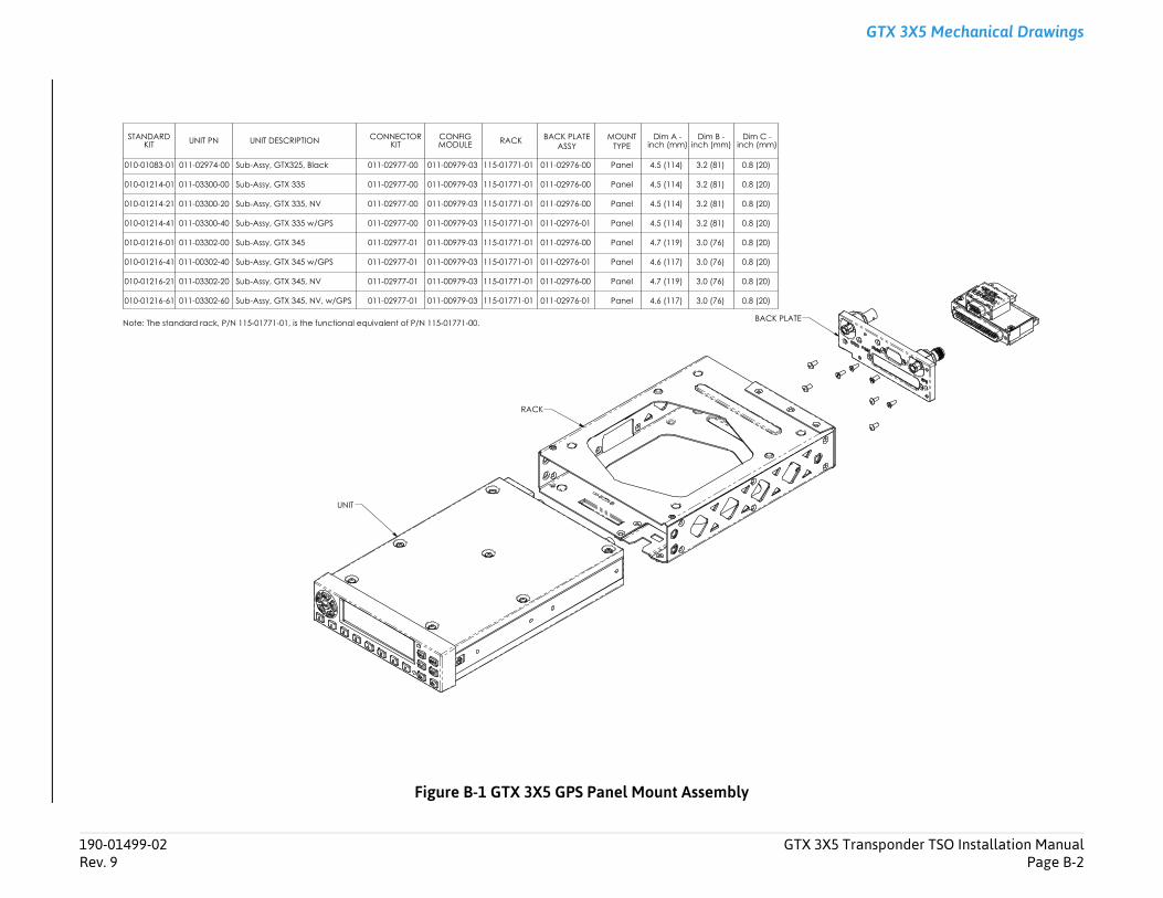
Transponder TSO Installation ManualPage B-2
GTX 3X5 Mechanical Drawings
190-01499-02 GTX 3X5Rev. 9
Figure B-1 GTX 3X5 GPS Panel Mount Assembly
UNIT
RACK
BACK PLATE
STANDARD KIT UNIT PN UNIT DESCRIPTION CONNECTOR
KITCONFIG MODULE RACK BACK PLATE
ASSYMOUNT
TYPEDim A -
inch (mm)Dim B -
inch (mm)Dim C -
inch (mm)
010-01083-01 011-02974-00
010-01214-01 011-03300-00
010-01214-21 011-03300-20
010-01214-41 011-03300-40
010-01216-01 011-03302-00
010-01216-41 011-00302-40
010-01216-21 011-03302-20
010-01216-61 011-03302-60
Sub-Assy, GTX325, Black
Sub-Assy, GTX 335
Sub-Assy, GTX 335, NV
Sub-Assy, GTX 335 w/GPS
Sub-Assy, GTX 345
Sub-Assy, GTX 345 w/GPS
Sub-Assy, GTX 345, NV
Sub-Assy, GTX 345, NV, w/GPS
011-02977-00 011-00979-03 115-01771-01 011-02976-00
011-02977-00 011-00979-03 115-01771-01 011-02976-00
011-02977-00 011-00979-03 115-01771-01 011-02976-00
011-02977-00 011-00979-03 115-01771-01 011-02976-01
011-02977-01 011-00979-03 115-01771-01 011-02976-00
011-02977-01 011-00979-03 115-01771-01 011-02976-01
011-02977-01 011-00979-03 115-01771-01 011-02976-00
011-02977-01 011-00979-03 115-01771-01 011-02976-01
Panel
Panel
Panel
Panel
Panel
Panel
Panel
Panel
4.5 (114)
4.5 (114)
4.5 (114)
4.5 (114)
4.7 (119)
4.6 (117)
4.7 (119)
4.6 (117)
3.2 (81) 0.8 (20)
3.2 (81) 0.8 (20)
3.2 (81) 0.8 (20)
3.2 (81) 0.8 (20)
3.0 (76) 0.8 (20)
3.0 (76) 0.8 (20)
3.0 (76) 0.8 (20)
3.0 (76) 0.8 (20)
Note: The standard rack, P/N 115-01771-01, is the functional equivalent of P/N 115-01771-00.
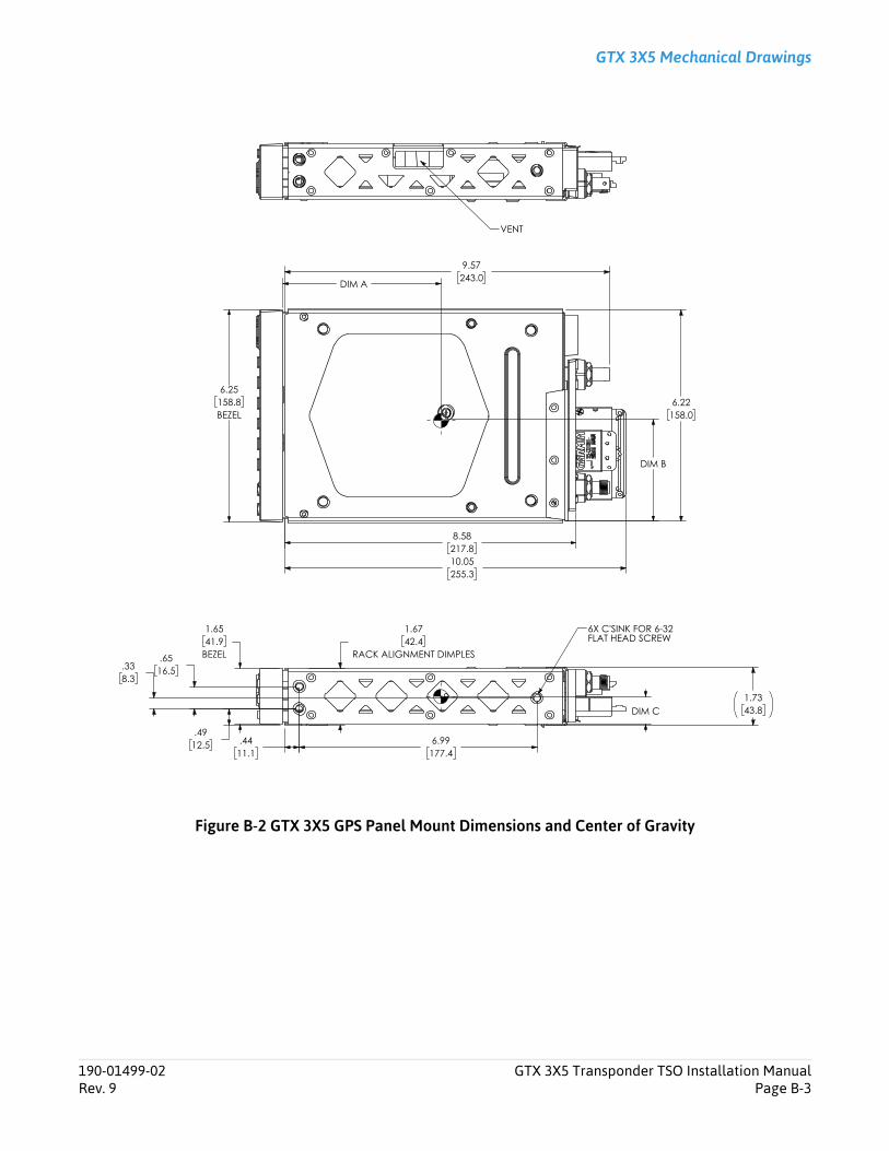
GTX 3X5 Mechanical Drawings
Figure B-2 GTX 3X5 GPS Panel Mount Dimensions and Center of Gravity
190-01499-02 GTX 3X5 Transponder TSO Installation ManualRev. 9 Page B-3
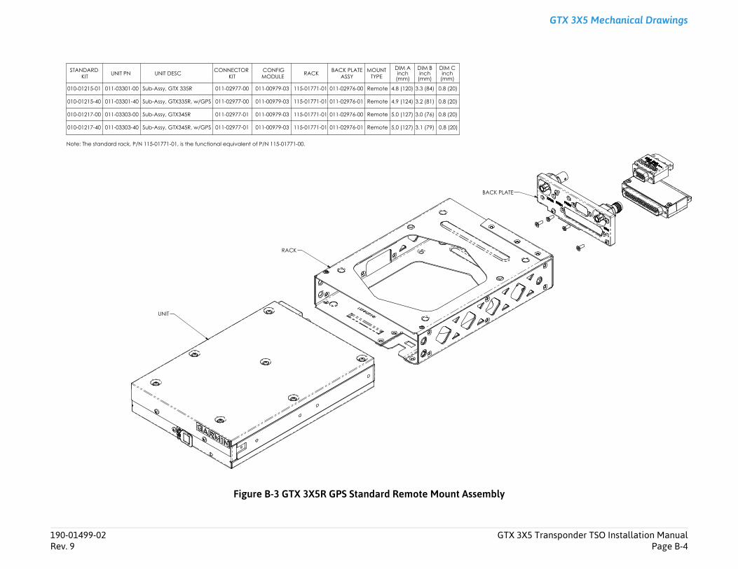
Transponder TSO Installation ManualPage B-4
GTX 3X5 Mechanical Drawings
190-01499-02 GTX 3X5Rev. 9
Figure B-3 GTX 3X5R GPS Standard Remote Mount Assembly
UNIT
RACK
BACK PLATE
STANDARD KIT UNIT PN UNIT DESC CONNECTOR
KITCONFIGMODULE RACK BACK PLATE
ASSYMOUNT
TYPEDIM A inch (mm)
DIM B inch (mm)
DIM C inch (mm)
010-01215-01 011-03301-00
010-01215-40 011-03301-40
010-01217-00 011-03303-00
010-01217-40 011-03303-40
Sub-Assy, GTX 335R
Sub-Assy, GTX335R, w/GPS
Sub-Assy, GTX345R
Sub-Assy, GTX345R, w/GPS
011-02977-00 011-00979-03
011-02977-00 011-00979-03
011-02977-01 011-00979-03
011-02977-01 011-00979-03
115-01771-01
115-01771-01
115-01771-01
115-01771-01
011-02976-00
011-02976-01
011-02976-00
011-02976-01
Remote
Remote
Remote
Remote
4.8 (120)
4.9 (124)
5.0 (127)
5.0 (127)
3.3 (84) 0.8 (20)
3.2 (81) 0.8 (20)
3.0 (76) 0.8 (20)
3.1 (79) 0.8 (20)
Note: The standard rack, P/N 115-01771-01, is the functional equivalent of P/N 115-01771-00.
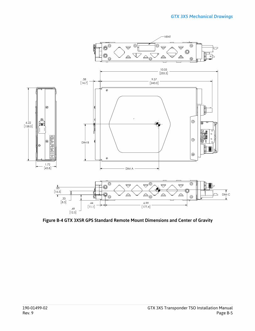
GTX 3X5 Mechanical Drawings
Figure B-4 GTX 3X5R GPS Standard Remote Mount Dimensions and Center of Gravity
190-01499-02 GTX 3X5 Transponder TSO Installation ManualRev. 9 Page B-5
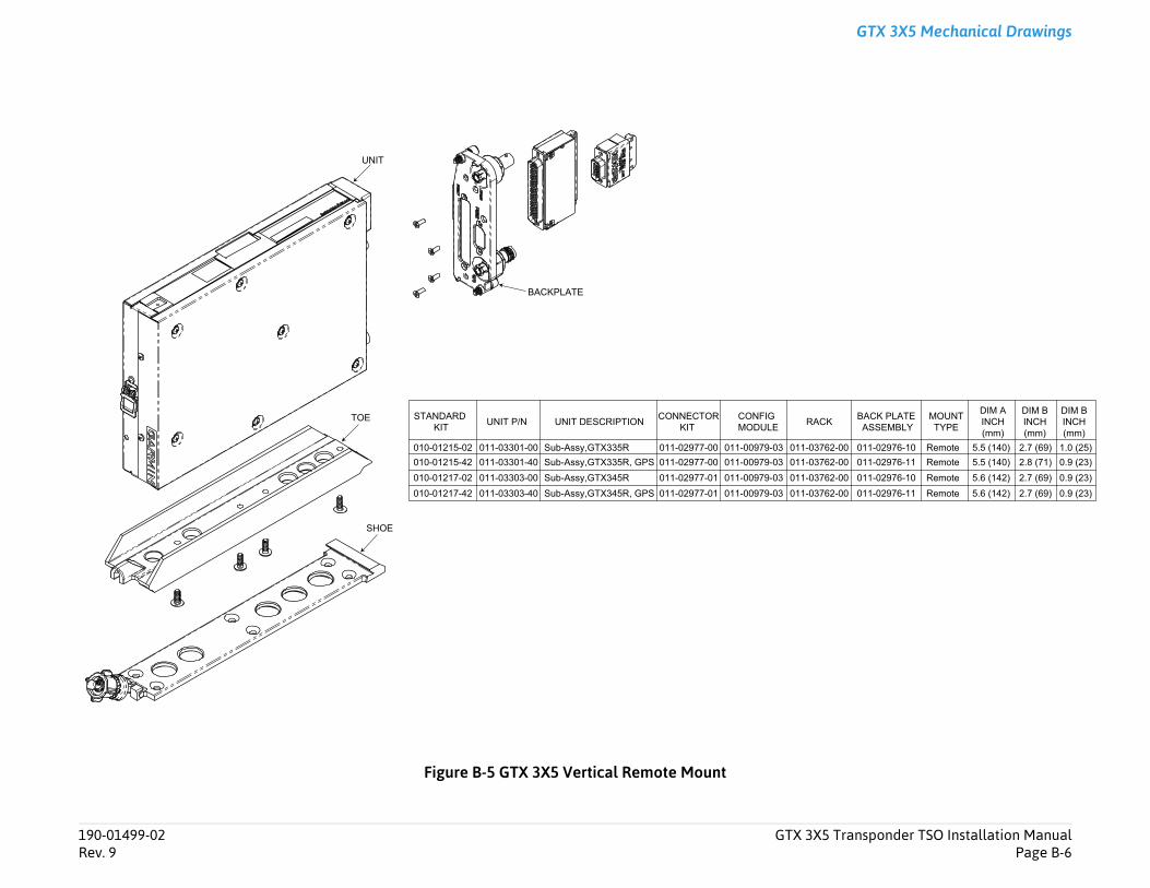
Transponder TSO Installation ManualPage B-6
GTX 3X5 Mechanical Drawings
BACK PLATE ASSEMBLYK MOUNT
TYPE
DIM AINCH(mm)
DIM BINCH(mm)
DIM BINCH(mm)
62-00 011-02976-10 Remote 5.5 (140) 2.7 (69) 1.0 (25)62-00 011-02976-11 Remote 5.5 (140) 2.8 (71) 0.9 (23)62-00 011-02976-10 Remote 5.6 (142) 2.7 (69) 0.9 (23)62-00 011-02976-11 Remote 5.6 (142) 2.7 (69) 0.9 (23)
190-01499-02 GTX 3X5Rev. 9
Figure B-5 GTX 3X5 Vertical Remote Mount
STANDARD KIT
TOE UNIT P/N UNIT DESCRIPTION CONNECTORKIT
CONFIGMODULE RAC
010-01215-02 011-03301-00 Sub-Assy,GTX335R 011-02977-00 011-00979-03 011-037010-01215-42 011-03301-40 Sub-Assy,GTX335R, GPS 011-02977-00 011-00979-03 011-037010-01217-02 011-03303-00 Sub-Assy,GTX345R 011-02977-01 011-00979-03 011-037010-01217-42 011-03303-40 Sub-Assy,GTX345R, GPS 011-02977-01 011-00979-03 011-037
SHOE
UNIT
BACKPLATE
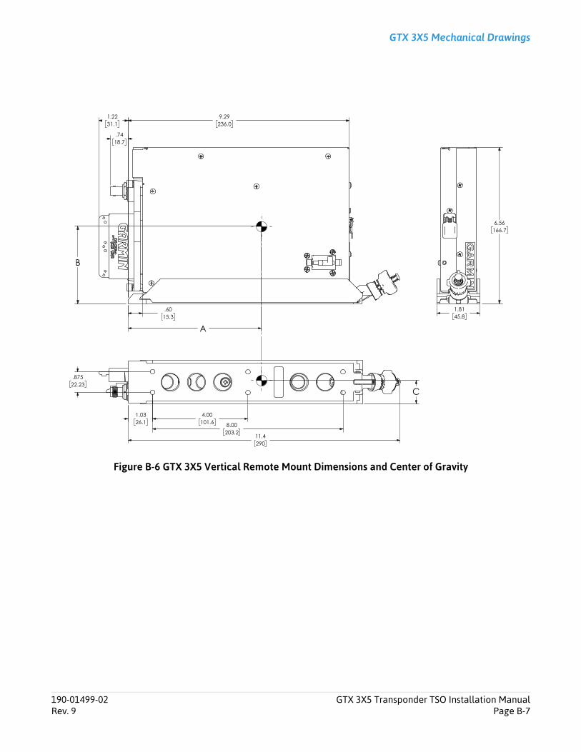
GTX 3X5 Mechanical Drawings
Figure B-6 GTX 3X5 Vertical Remote Mount Dimensions and Center of Gravity
1.8145.8
6.56166.7
.6015.3
1.2231.1
.7418.7
9.29236.0
B
A
1.0326.1
4.00101.6
8.00203.2
.87522.23
C
11.4290
190-01499-02 GTX 3X5 Transponder TSO Installation ManualRev. 9 Page B-7
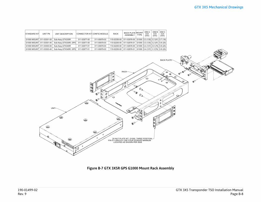
Transponder TSO Installation ManualPage B-8
GTX 3X5 Mechanical Drawings
190-01499-02 GTX 3X5Rev. 9
Figure B-7 GTX 3X5R GPS G1000 Mount Rack Assembly
UNIT
RACK
BACK PLATE
2X NUT PLATE KIT, G1000, THREE POSITION,P/N 011-00915-01 USE FOUR SCREWS MINIMUM
LOCATED AS SHOWN PER SIDE
STANDARD KIT UNIT PN UNIT DESCRIPTION CONNECTOR KIT CONFIG MODULE RACK BACK PLATEASSEMBLY
MOUNTTYPE
DIM Ainch (mm)
DIM B inch (mm)
DIM C inch (mm)
G1000 MOUNT 011-03301-00 Sub-Assy,GTX335R 011-02977-00 011-00979-03 115-02250-00 011-02976-00 G1000 5.3 (135) 3.2 (81) 0.7 (18)
G1000 MOUNT 011-03301-40 Sub-Assy,GTX335R, GPS 011-02977-00 011-00979-03 115-02250-00 011-02976-01 G1000 5.3 (135) 3.2 (81) 0.8 (20)
G1000 MOUNT 011-03303-00 Sub-Assy,GTX345R 011-02977-01 011-00979-03 115-02250-00 011-02976-00 G1000 5.4 (137) 3.0 (76) 0.8 (20)
G1000 MOUNT 011-03303-40 Sub-Assy,GTX345R, GPS 011-02977-01 011-00979-03 115-02250-00 011-02976-01 G1000 5.4 (137) 3.1(79) 0.8 (20)
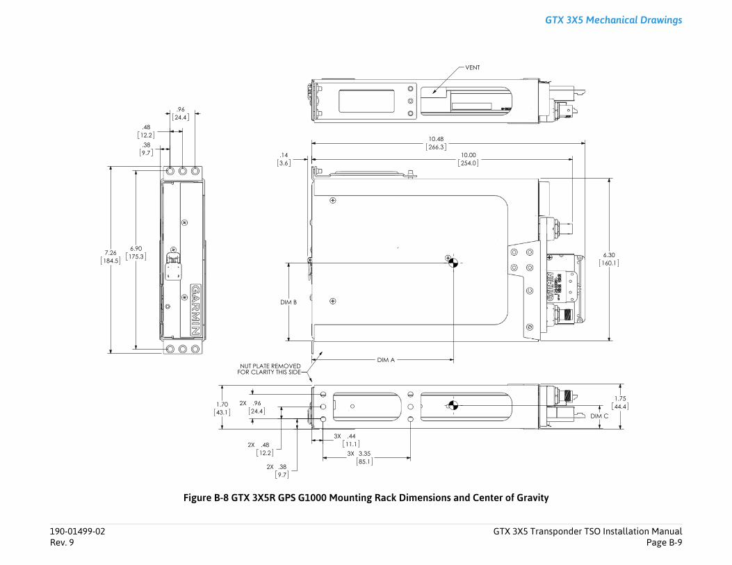
Transponder TSO Installation ManualPage B-9
GTX 3X5 Mechanical Drawings
avity
1.7544.4
DIM C
6.30160.1
190-01499-02 GTX 3X5Rev. 9
Figure B-8 GTX 3X5R GPS G1000 Mounting Rack Dimensions and Center of Gr
2X .389.7
2X .4812.2
2X .9624.4
3X .4411.13X 3.35
85.1
1.7043.1
NUT PLATE REMOVED FOR CLARITY THIS SIDE
10.48266.3
10.00254.0
.143.6
DIM A
DIM B
VENT
6.90175.37.26
184.5
.389.7
.4812.2
.9624.4

GTX 3X5 Mechanical Drawings
Figure B-9 GTX 3X5 Panel Cutout Detail
190-01499-02 GTX 3X5 Transponder TSO Installation ManualRev. 9 Page B-10
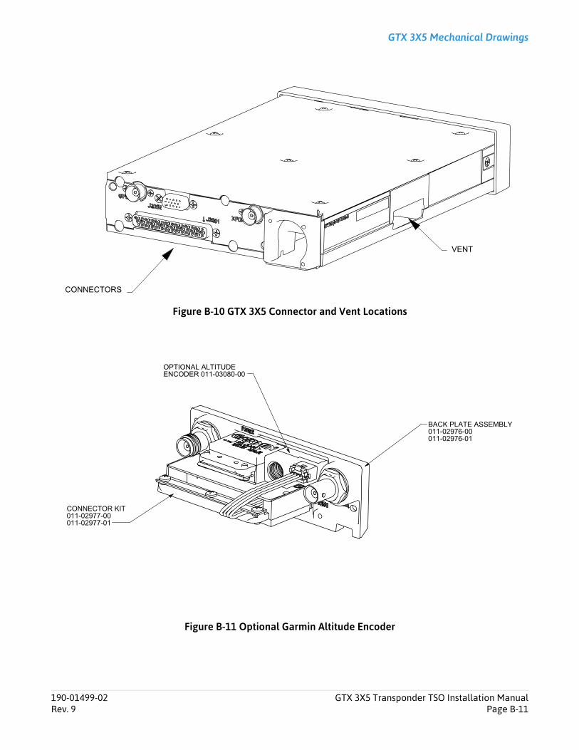
GTX 3X5 Mechanical Drawings
Figure B-10 GTX 3X5 Connector and Vent Locations
Figure B-11 Optional Garmin Altitude Encoder
CONNECTORS
VENT
BACK PLATE ASSEMBLY011-02976-00011-02976-01
CONNECTOR KIT011-02977-00011-02977-01
OPTIONAL ALTITUDE ENCODER 011-03080-00
190-01499-02 GTX 3X5 Transponder TSO Installation ManualRev. 9 Page B-11
Equipment Compatibility and Configuration
Appendix C Equipment Compatibility and Configuration
C.1 ADS-B In Displays...........................................................................................................................................C-2C.2 GPS Sources ..................................................................................................................................................C-3C.3 Altitude Sources ............................................................................................................................................C-4C.4 Audio Panels..................................................................................................................................................C-6C.5 Radar Altimeters ............................................................................................................................................C-6C.6 Heading Reference Sources............................................................................................................................C-7C.7 Traffic Sensors (GTX 345 Only).......................................................................................................................C-9C.8 Bluetooth ....................................................................................................................................................C-10C.9 Remote Control ...........................................................................................................................................C-11C.10 TIS-A Display................................................................................................................................................C-12
190-01499-02 GTX 3X5 Transponder TSO Installation ManualRev. 9 Page C-1
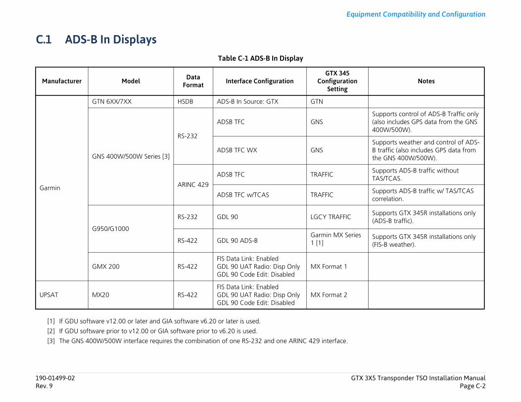
Transponder TSO Installation ManualPage C-2
Equipment Compatibility and Configuration
Notes
upports control of ADS-B Traffic only also includes GPS data from the GNS 00W/500W).
upports weather and control of ADS- traffic (also includes GPS data from he GNS 400W/500W).
upports ADS-B traffic without AS/TCAS.
upports ADS-B traffic w/ TAS/TCAS orrelation.
upports GTX 345R installations only ADS-B traffic).
upports GTX 345R installations only FIS-B weather).
190-01499-02 GTX 3X5Rev. 9
C.1 ADS-B In DisplaysTable C-1 ADS-B In Display
[1] If GDU software v12.00 or later and GIA software v6.20 or later is used.
[2] If GDU software prior to v12.00 or GIA software prior to v6.20 is used.
[3] The GNS 400W/500W interface requires the combination of one RS-232 and one ARINC 429 interface.
Manufacturer Model Data Format Interface Configuration
GTX 345 Configuration
Setting
Garmin
GTN 6XX/7XX HSDB ADS-B In Source: GTX GTN
GNS 400W/500W Series [3]
RS-232
ADSB TFC GNSS(4
ADSB TFC WX GNSSBt
ARINC 429
ADSB TFC TRAFFICST
ADSB TFC w/TCAS TRAFFICSc
G950/G1000
RS-232 GDL 90 LGCY TRAFFICS(
RS-422 GDL 90 ADS-BGarmin MX Series 1 [1]
S(
GMX 200 RS-422FIS Data Link: Enabled GDL 90 UAT Radio: Disp Only GDL 90 Code Edit: Disabled
MX Format 1
UPSAT MX20 RS-422FIS Data Link: Enabled GDL 90 UAT Radio: Disp Only GDL 90 Code Edit: Disabled
MX Format 2
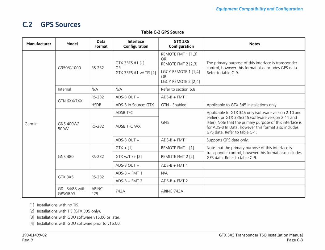
Transponder TSO Installation ManualPage C-3
Equipment Compatibility and Configuration
Notes
rpose of this interface is transponder er this format also includes GPS data. -9.
TX 345 installations only.
TX 345 only (software version 2.10 and 335/345 (software version 2.11 and t the primary purpose of this interface is ta, however this format also includes to table C-1.
ata only.
rimary purpose of this interface is ntrol, however this format also includes to table C-9.
190-01499-02 GTX 3X5Rev. 9
C.2 GPS SourcesTable C-2 GPS Source
[1] Installations with no TIS.
[2] Installations with TIS (GTX 335 only).
[3] Installations with GDU software v15.00 or later.
[4] Installations with GDU software prior to v15.00.
Manufacturer Model Data Format
Interface Configuration
GTX 3X5 Configuration
Garmin
G950/G1000 RS-232GTX 33ES #1 [1]ORGTX 33ES #1 w/ TIS [2]
REMOTE FMT 1 [1,3]ORREMOTE FMT 2 [2,3] The primary pu
control, howevRefer to table CLGCY REMOTE 1 [1,4]
ORLGCY REMOTE 2 [2,4]
Internal N/A N/A Refer to section 6.8.
GTN 6XX/7XXRS-232 ADS-B OUT + ADS-B + FMT 1
HSDB ADS-B In Source: GTX GTN - Enabled Applicable to G
GNS 400W/500W
RS-232
ADSB TFC
GNS
Applicable to Gearlier), or GTXlater). Note thafor ADS-B In DaGPS data. Refer
ADSB TFC WX
ADS-B OUT + ADS-B + FMT 1 Supports GPS d
GNS 480 RS-232
GTX + [1] REMOTE FMT 1 [1] Note that the ptransponder coGPS data. ReferGTX w/TIS+ [2] REMOTE FMT 2 [2]
ADS-B OUT + ADS-B + FMT 1
GTX 3X5 RS-232ADS-B + FMT 1 N/A
ADS-B + FMT 2 ADS-B + FMT 2
GDL 84/88 with GPS/SBAS
ARINC 429
743A ARINC 743A
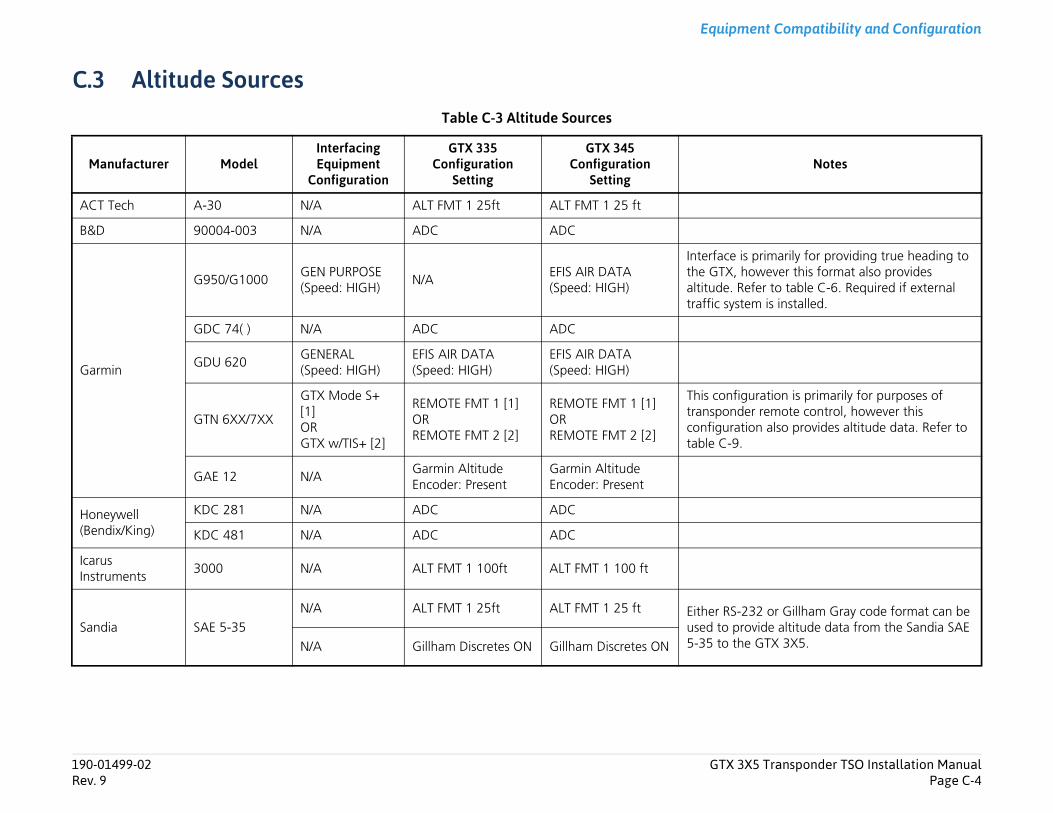
Transponder TSO Installation ManualPage C-4
Equipment Compatibility and Configuration
Notes
rimarily for providing true heading to wever this format also provides er to table C-6. Required if external is installed.
ration is primarily for purposes of remote control, however this n also provides altitude data. Refer to
2 or Gillham Gray code format can be ide altitude data from the Sandia SAE GTX 3X5.
190-01499-02 GTX 3X5Rev. 9
C.3 Altitude SourcesTable C-3 Altitude Sources
Manufacturer ModelInterfacing Equipment
Configuration
GTX 335 Configuration
Setting
GTX 345 Configuration
Setting
ACT Tech A-30 N/A ALT FMT 1 25ft ALT FMT 1 25 ft
B&D 90004-003 N/A ADC ADC
Garmin
G950/G1000GEN PURPOSE(Speed: HIGH)
N/AEFIS AIR DATA(Speed: HIGH)
Interface is pthe GTX, hoaltitude. Reftraffic system
GDC 74( ) N/A ADC ADC
GDU 620GENERAL(Speed: HIGH)
EFIS AIR DATA(Speed: HIGH)
EFIS AIR DATA(Speed: HIGH)
GTN 6XX/7XX
GTX Mode S+ [1]ORGTX w/TIS+ [2]
REMOTE FMT 1 [1]ORREMOTE FMT 2 [2]
REMOTE FMT 1 [1]ORREMOTE FMT 2 [2]
This configutransponderconfiguratiotable C-9.
GAE 12 N/AGarmin Altitude Encoder: Present
Garmin Altitude Encoder: Present
Honeywell (Bendix/King)
KDC 281 N/A ADC ADC
KDC 481 N/A ADC ADC
Icarus Instruments
3000 N/A ALT FMT 1 100ft ALT FMT 1 100 ft
Sandia SAE 5-35N/A ALT FMT 1 25ft ALT FMT 1 25 ft Either RS-23
used to prov5-35 to the N/A Gillham Discretes ON Gillham Discretes ON

Transponder TSO Installation ManualPage C-5
Equipment Compatibility and Configuration
installations with the 8800T unit or 25ft or lower encoding.
installations with the 8800T unit or parallel Gray source or 100 ft
-232 or ARINC 429 data format can the Shadin F/ADC-2000 interface to t both).
installations with the SSD120 unit or 25ft or lower encoding.
installations with the SSD120 unit or parallel Gray source or 100 ft
Notes
190-01499-02 GTX 3X5Rev. 9
[1] Installation with no TIS traffic.
[2] Installation with TIS traffic (GTX 335 only).
Shadin
8800T
25 ft or lower encoding
ALT FMT 3 25 ft ALT FMT 3 25 ftApplicable toconfigured f
100 ft encoding ALT FMT 3 100 ft ALT FMT 3 100 ftApplicable toconfigured fencoding.
F/ADC-200 N/A ADC FMT 1 ADC FMT 1
F/ADC-2000
N/A ADC FMT 1 ADC FMT 1Either the RSbe used for the GTX (no
N/A ADC (Speed: LOW) ADC (Speed: LOW)
Trans-Cal Industries
IA-RS232-X N/A ALT FMT 1 100 ft ALT FMT 1 100 ft
SSD120
25 ft or lower encoding
ALT FMT 1 25 ft ALT FMT 1 25 ftApplicable toconfigured f
100 ft encoding ALT FMT 1 100 ftALT FMT 1 100 ft
Applicable toconfigured fencoding.
Manufacturer ModelInterfacing Equipment
Configuration
GTX 335 Configuration
Setting
GTX 345 Configuration
Setting
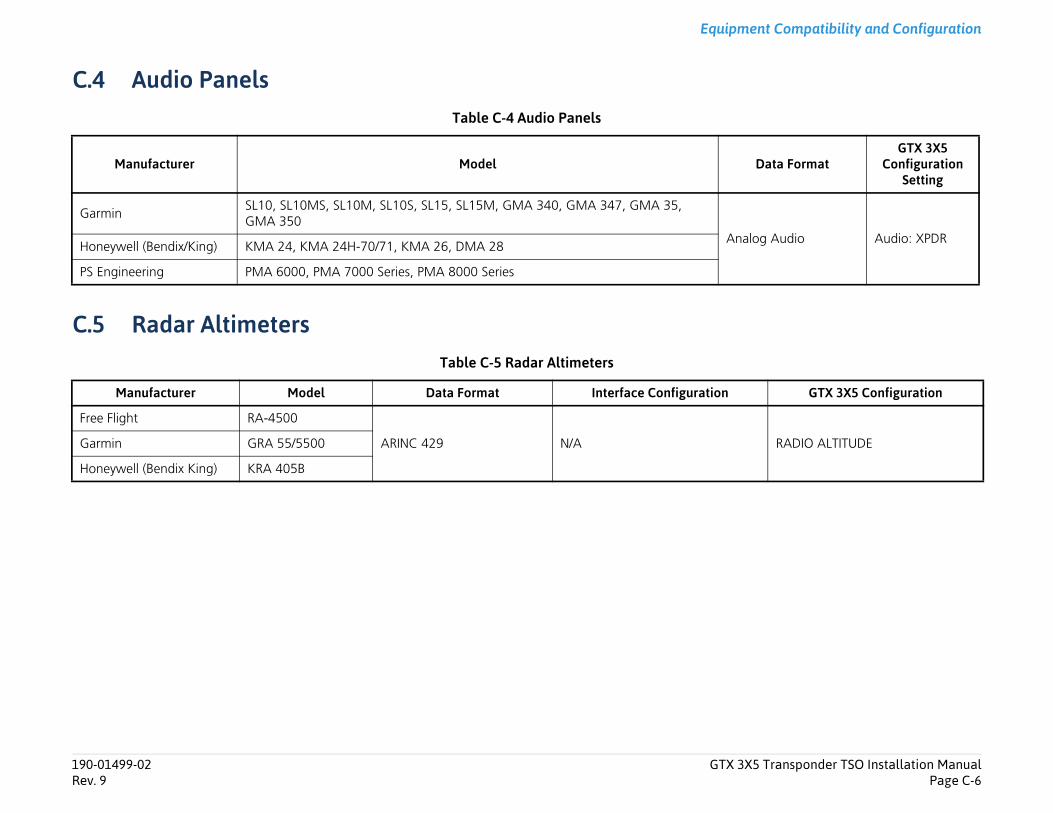
Transponder TSO Installation ManualPage C-6
Equipment Compatibility and Configuration
Data FormatGTX 3X5
Configuration Setting
g Audio Audio: XPDR
GTX 3X5 Configuration
RADIO ALTITUDE
190-01499-02 GTX 3X5Rev. 9
C.4 Audio PanelsTable C-4 Audio Panels
C.5 Radar AltimetersTable C-5 Radar Altimeters
Manufacturer Model
GarminSL10, SL10MS, SL10M, SL10S, SL15, SL15M, GMA 340, GMA 347, GMA 35, GMA 350
AnaloHoneywell (Bendix/King) KMA 24, KMA 24H-70/71, KMA 26, DMA 28
PS Engineering PMA 6000, PMA 7000 Series, PMA 8000 Series
Manufacturer Model Data Format Interface Configuration
Free Flight RA-4500
ARINC 429 N/AGarmin GRA 55/5500
Honeywell (Bendix King) KRA 405B
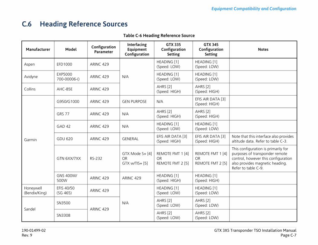
Transponder TSO Installation ManualPage C-7
Equipment Compatibility and Configuration
Notes
Note that this interface also provides altitude data. Refer to table C-3.
This configuration is primarily for purposes of transponder remote control, however this configuration also provides magnetic heading. Refer to table C-9.
190-01499-02 GTX 3X5Rev. 9
C.6 Heading Reference SourcesTable C-6 Heading Reference Source
Manufacturer Model Configuration Parameter
Interfacing Equipment
Configuration
GTX 335 Configuration
Setting
GTX 345 Configuration
Setting
Aspen EFD1000 ARINC 429
N/A
HEADING [1] (Speed: LOW)
HEADING [1] (Speed: LOW)
AvidyneEXP5000700-00006-()
ARINC 429 HEADING [1] (Speed: LOW)
HEADING [1] (Speed: LOW)
Collins AHC-85E ARINC 429AHRS [2] (Speed: HIGH)
AHRS [2] (Speed: HIGH)
Garmin
G950/G1000 ARINC 429 GEN PURPOSE N/AEFIS AIR DATA [3](Speed: HIGH)
GRS 77 ARINC 429 N/AAHRS [2] (Speed: HIGH)
AHRS [2] (Speed: HIGH)
GAD 42 ARINC 429 N/AHEADING [1] (Speed: LOW)
HEADING [1] (Speed: LOW)
GDU 620 ARINC 429 GENERALEFIS AIR DATA [3] (Speed: HIGH)
EFIS AIR DATA [3] (Speed: HIGH)
GTN 6XX/7XX RS-232GTX Mode S+ [4]ORGTX w/TIS+ [5]
REMOTE FMT 1 [4]ORREMOTE FMT 2 [5]
REMOTE FMT 1 [4]ORREMOTE FMT 2 [5]
GNS 400W/500W
ARINC 429 ARINC 429HEADING [1] (Speed: HIGH)
HEADING [1] (Speed: HIGH)
Honeywell (Bendix/King)
EFIS 40/50 (SG 465)
ARINC 429
N/A
HEADING [1] (Speed: LOW)
HEADING [1] (Speed: LOW)
Sandel
SN3500
ARINC 429
AHRS [2] (Speed: LOW)
AHRS [2] (Speed: LOW)
SN3308AHRS [2] (Speed: LOW)
AHRS [2] (Speed: LOW)
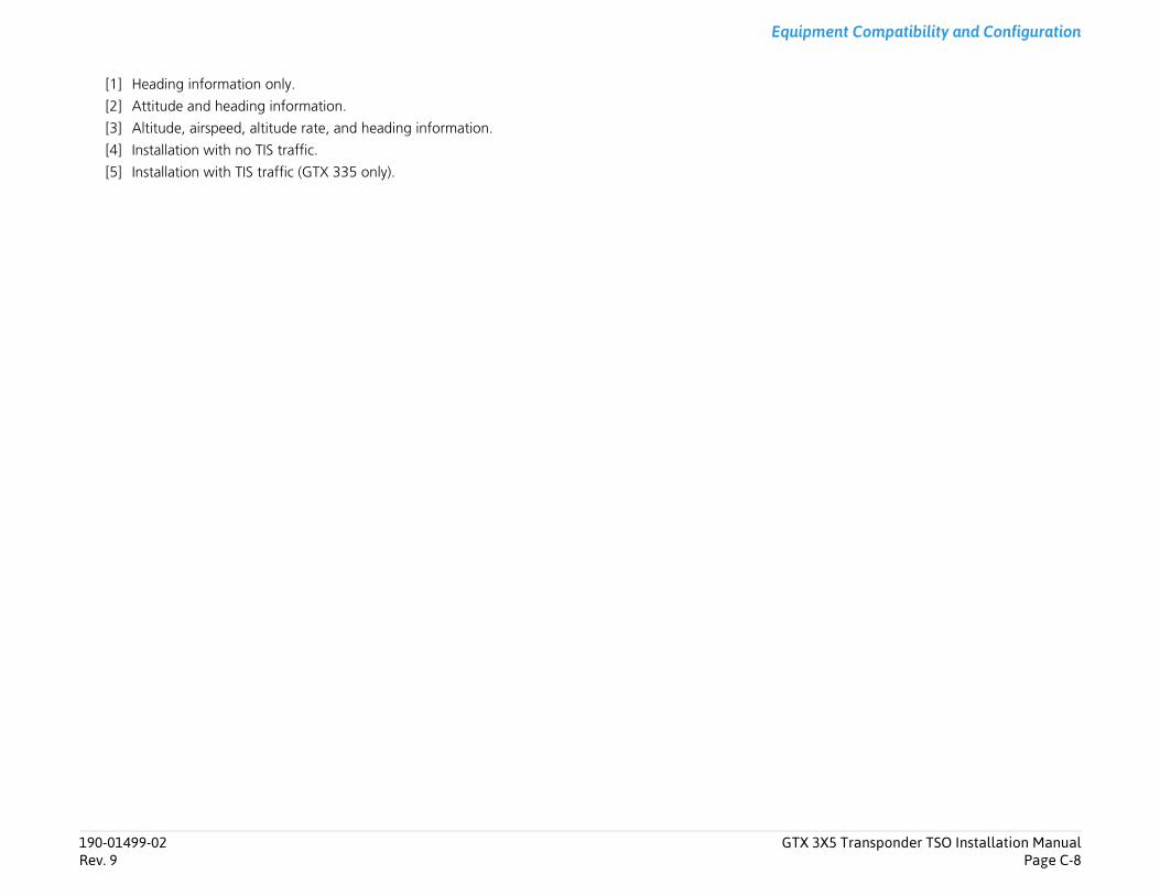
Transponder TSO Installation ManualPage C-8
Equipment Compatibility and Configuration
190-01499-02 GTX 3X5Rev. 9
[1] Heading information only.
[2] Attitude and heading information.
[3] Altitude, airspeed, altitude rate, and heading information.
[4] Installation with no TIS traffic.
[5] Installation with TIS traffic (GTX 335 only).
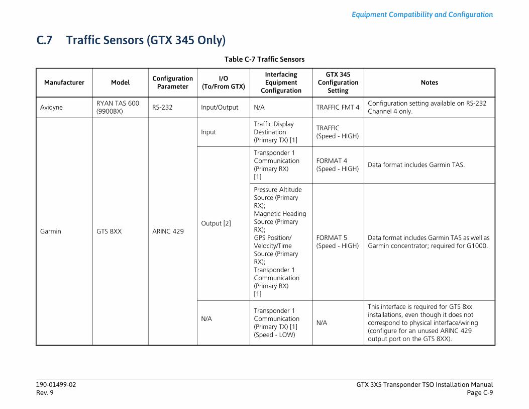
Transponder TSO Installation ManualPage C-9
Equipment Compatibility and Configuration
Notes
figuration setting available on RS-232 nnel 4 only.
format includes Garmin TAS.
format includes Garmin TAS as well as in concentrator; required for G1000.
interface is required for GTS 8xx llations, even though it does not
espond to physical interface/wiring figure for an unused ARINC 429 ut port on the GTS 8XX).
190-01499-02 GTX 3X5Rev. 9
C.7 Traffic Sensors (GTX 345 Only)Table C-7 Traffic Sensors
Manufacturer Model Configuration Parameter
I/O(To/From GTX)
Interfacing Equipment
Configuration
GTX 345 Configuration
Setting
AvidyneRYAN TAS 600 (9900BX)
RS-232 Input/Output N/A TRAFFIC FMT 4ConCha
Garmin GTS 8XX ARINC 429
InputTraffic Display Destination (Primary TX) [1]
TRAFFIC(Speed - HIGH)
Output [2]
Transponder 1 Communication (Primary RX)[1]
FORMAT 4(Speed - HIGH)
Data
Pressure Altitude Source (Primary RX);Magnetic Heading Source (Primary RX);GPS Position/Velocity/Time Source (Primary RX);Transponder 1 Communication (Primary RX)[1]
FORMAT 5(Speed - HIGH)
DataGarm
N/ATransponder 1 Communication (Primary TX) [1](Speed - LOW)
N/A
Thisinstacorr(conoutp
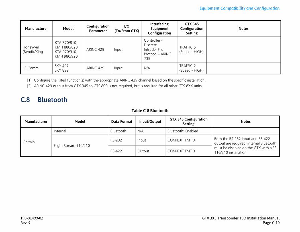
Transponder TSO Installation ManualPage C-10
Equipment Compatibility and Configuration
Notes
oth the RS-232 input and RS-422 utput are required; internal Bluetooth ust be disabled on the GTX with a FS 10/210 installation.
Notes
190-01499-02 GTX 3X5Rev. 9
[1] Configure the listed function(s) with the appropriate ARINC 429 channel based on the specific installation.
[2] ARINC 429 output from GTX 345 to GTS 800 is not required, but is required for all other GTS 8XX units.
C.8 BluetoothTable C-8 Bluetooth
Honeywell (Bendix/King
KTA 870/810KMH 880/820KTA 970/910KMH 980/920
ARINC 429 Input
Controller - DiscreteIntruder File Protocol - ARINC 735
TRAFFIC 5(Speed - HIGH)
L3 CommSKY 497SKY 899
ARINC 429 Input N/ATRAFFIC 2(Speed - HIGH)
Manufacturer Model Data Format Input/Output GTX 345 Configuration Setting
Garmin
Internal Bluetooth N/A Bluetooth: Enabled
Flight Stream 110/210RS-232 Input CONNEXT FMT 3 B
om1RS-422 Output CONNEXT FMT 3
Manufacturer Model Configuration Parameter
I/O(To/From GTX)
Interfacing Equipment
Configuration
GTX 345 Configuration
Setting
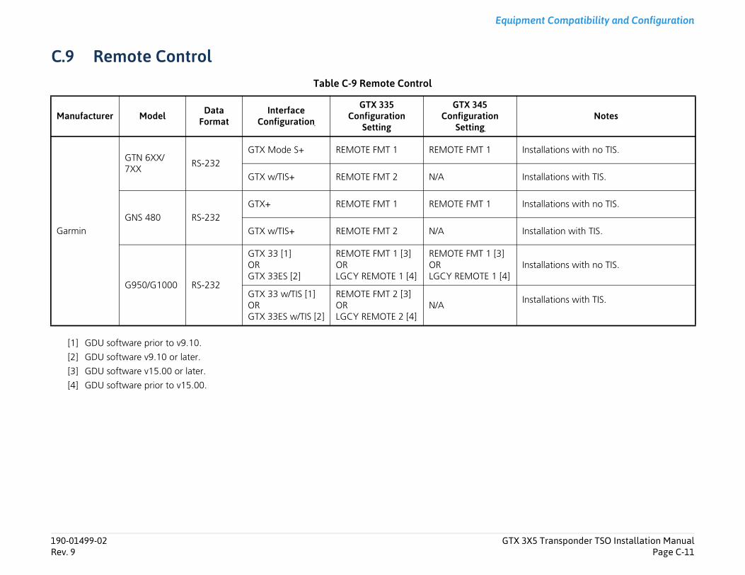
Transponder TSO Installation ManualPage C-11
Equipment Compatibility and Configuration
Notes
allations with no TIS.
allations with TIS.
allations with no TIS.
allation with TIS.
allations with no TIS.
allations with TIS.
190-01499-02 GTX 3X5Rev. 9
C.9 Remote ControlTable C-9 Remote Control
[1] GDU software prior to v9.10.
[2] GDU software v9.10 or later.
[3] GDU software v15.00 or later.
[4] GDU software prior to v15.00.
Manufacturer Model Data Format
Interface Configuration
GTX 335 Configuration
Setting
GTX 345 Configuration
Setting
Garmin
GTN 6XX/7XX
RS-232GTX Mode S+ REMOTE FMT 1 REMOTE FMT 1 Inst
GTX w/TIS+ REMOTE FMT 2 N/A Inst
GNS 480 RS-232GTX+ REMOTE FMT 1 REMOTE FMT 1 Inst
GTX w/TIS+ REMOTE FMT 2 N/A Inst
G950/G1000 RS-232
GTX 33 [1]ORGTX 33ES [2]
REMOTE FMT 1 [3]ORLGCY REMOTE 1 [4]
REMOTE FMT 1 [3]ORLGCY REMOTE 1 [4]
Inst
GTX 33 w/TIS [1]ORGTX 33ES w/TIS [2]
REMOTE FMT 2 [3]ORLGCY REMOTE 2 [4]
N/AInst
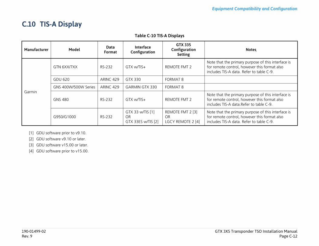
Transponder TSO Installation ManualPage C-12
Equipment Compatibility and Configuration
Notes
primary purpose of this interface is ntrol, however this format also data. Refer to table C-9.
primary purpose of this interface is ntrol, however this format also data.Refer to table C-9.
primary purpose of this interface is ntrol, however this format also data. Refer to table C-9.
190-01499-02 GTX 3X5Rev. 9
C.10 TIS-A DisplayTable C-10 TIS-A Displays
[1] GDU software prior to v9.10.
[2] GDU software v9.10 or later.
[3] GDU software v15.00 or later.
[4] GDU software prior to v15.00.
Manufacturer Model Data Format
Interface Configuration
GTX 335 Configuration
Setting
Garmin
GTN 6XX/7XX RS-232 GTX w/TIS+ REMOTE FMT 2Note that thefor remote coincludes TIS-A
GDU 620 ARINC 429 GTX 330 FORMAT 8
GNS 400W/500W Series ARINC 429 GARMIN GTX 330 FORMAT 8
GNS 480 RS-232 GTX w/TIS+ REMOTE FMT 2Note that thefor remote coincludes TIS-A
G950/G1000 RS-232GTX 33 w/TIS [1]ORGTX 33ES w/TIS [2]
REMOTE FMT 2 [3]ORLGCY REMOTE 2 [4]
Note that thefor remote coincludes TIS-A
Interconnect Drawings
Appendix D Interconnect DrawingsFigure D-1 GTX 3X5 Power Configuration Typical Interconnect ...........................................................................D-3Figure D-2 GTX 345 - G1000 Interconnect ..........................................................................................................D-5Figure D-3 GTX 335 - G1000 Interconnect ..........................................................................................................D-7Figure D-4 GTX 3X5 - GNS 480 (CNX80) Interconnect ........................................................................................D-8Figure D-5 GTX 335 - GTN 6XX/7XX Typical Interconnect ...................................................................................D-9Figure D-6 Single/Dual GTX 335 - Single GTN 6XX/7XX Interconnect ................................................................D-10Figure D-7 GTX 345 - GTN 6XX/7XX Typical Interconnect .................................................................................D-11Figure D-8 GTX 345 - Single/Dual GTN 6XX/7XX Interconnect ...........................................................................D-13Figure D-9 GTX 335/345 - GDL 88 Interconnect ................................................................................................D-14Figure D-10 GTX 345 - Traffic Sensor Interconnect ..............................................................................................D-15Figure D-11 GTX 345 - Single and Dual 400W/500W Series ................................................................................D-19Figure D-12 GTX 3X5 - Audio Interconnect .........................................................................................................D-20Figure D-13 GTX 3X5 - Radio Altimeter Interconnect ..........................................................................................D-21Figure D-14 GTX 3X5 - AHRS/Heading Source .....................................................................................................D-22Figure D-15 GTX 3X5 - Switches and OAT Probe Interconnect ............................................................................D-23Figure D-16 GTX 3X5 - Altitude Source Interconnect ...........................................................................................D-24Figure D-17 GTX 335 - GNS 400W/500W Series Interconnect .............................................................................D-26Figure D-18 GTX 345/345R - Flight Stream Interconnect .....................................................................................D-27Figure D-19 GTX 345 - MX20/GMX 200 Interconnect .........................................................................................D-28Figure D-20 GTX 335 - GDU 620 Interconnect ....................................................................................................D-28
190-01499-02 GTX 3X5 Transponder TSO Installation ManualRev. 9 Page D-1
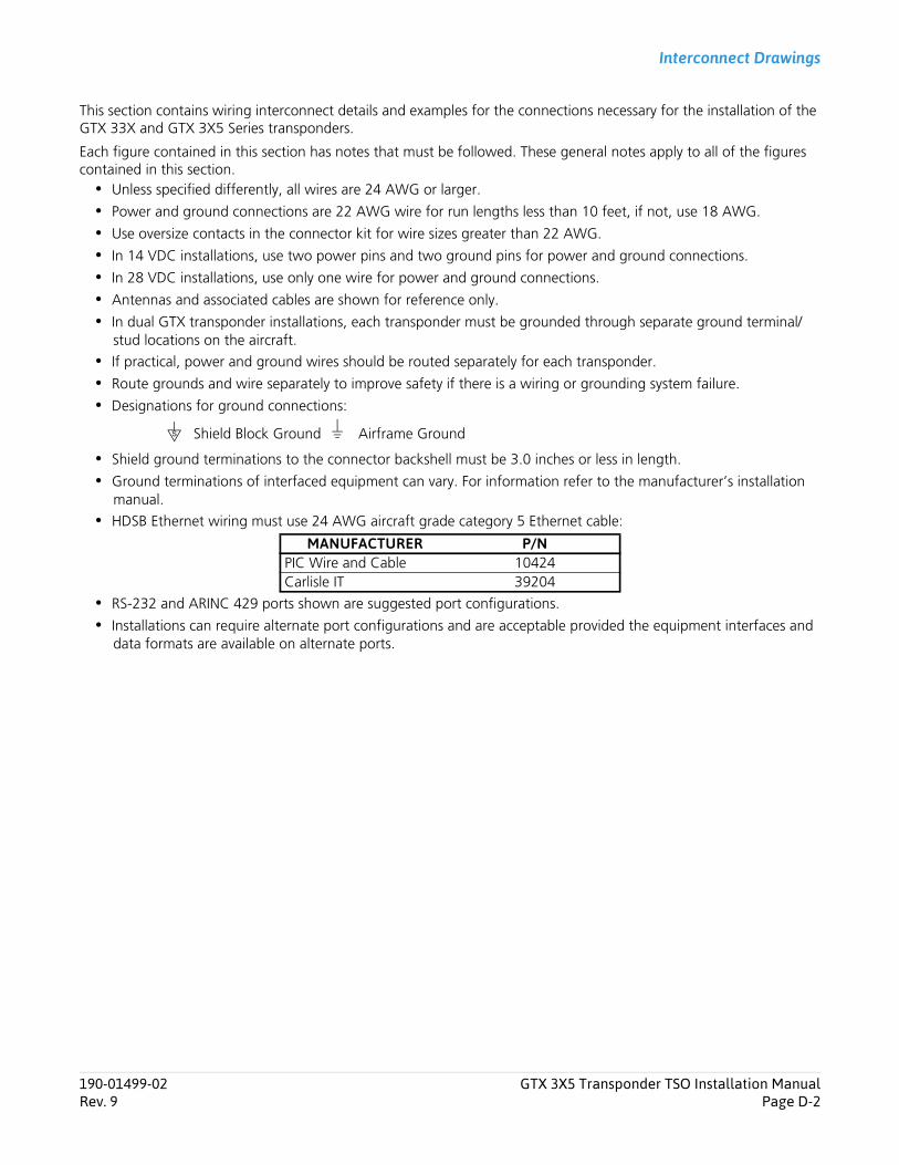
Interconnect Drawings
This section contains wiring interconnect details and examples for the connections necessary for the installation of the GTX 33X and GTX 3X5 Series transponders.
Each figure contained in this section has notes that must be followed. These general notes apply to all of the figures contained in this section. Unless specified differently, all wires are 24 AWG or larger.
Power and ground connections are 22 AWG wire for run lengths less than 10 feet, if not, use 18 AWG.
Use oversize contacts in the connector kit for wire sizes greater than 22 AWG.
In 14 VDC installations, use two power pins and two ground pins for power and ground connections.
In 28 VDC installations, use only one wire for power and ground connections.
Antennas and associated cables are shown for reference only.
In dual GTX transponder installations, each transponder must be grounded through separate ground terminal/stud locations on the aircraft.
If practical, power and ground wires should be routed separately for each transponder.
Route grounds and wire separately to improve safety if there is a wiring or grounding system failure.
Designations for ground connections:
Shield ground terminations to the connector backshell must be 3.0 inches or less in length.
Ground terminations of interfaced equipment can vary. For information refer to the manufacturer’s installation manual.
HDSB Ethernet wiring must use 24 AWG aircraft grade category 5 Ethernet cable:
RS-232 and ARINC 429 ports shown are suggested port configurations.
Installations can require alternate port configurations and are acceptable provided the equipment interfaces and data formats are available on alternate ports.
Shield Block Ground Airframe Ground
MANUFACTURER P/NPIC Wire and Cable 10424Carlisle IT 39204
S
190-01499-02 GTX 3X5 Transponder TSO Installation ManualRev. 9 Page D-2
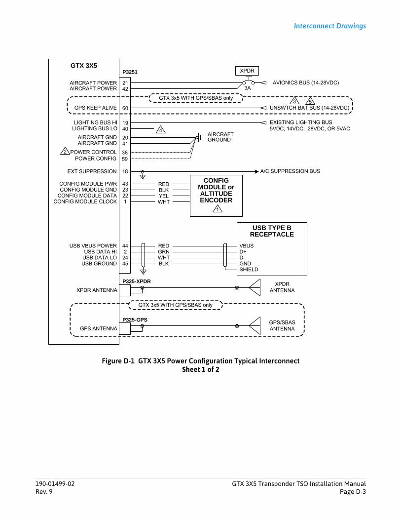
Interconnect Drawings
Figure D-1 GTX 3X5 Power Configuration Typical InterconnectSheet 1 of 2
P3251GTX 3X5
CONFIG MODULE PWRCONFIG MODULE GND
CONFIG MODULE DATACONFIG MODULE CLOCK
CONFIG MODULE orALTITUDE ENCODER
4323221
AIRCRAFT POWER
AIRCRAFT GND
21
20
P325-GPS GPS/SBAS ANTENNA
XPDR ANTENNA
P325-XPDR XPDR ANTENNA
GPS ANTENNA
AIRCRAFT POWER 42
AIRCRAFT GND 41
XPDR
AVIONICS BUS (14-28VDC)
AIRCRAFTGROUND
3A
USB VBUS POWERUSB DATA HI
USB DATA LOUSB GROUND
442
2445
POWER CONTROL 38
GPS KEEP ALIVE 60 UNSWTCH BAT BUS (14-28VDC)
19 EXISTING LIGHTING BUS 5VDC, 14VDC, 28VDC, OR 5VAC40
RED
YELBLK
WHT
REDGRN
BLKWHT
S
LIGHTING BUS LOLIGHTING BUS HI
VBUSD+D-GND
USB TYPE BRECEPTACLE
SHIELD
1
GTX 3x5 WITH GPS/SBAS only
2
GTX 3x5 WITH GPS/SBAS only
3
POWER CONFIG 59
18s
EXT SUPPRESSION A/C SUPPRESSION BUS
4
5
190-01499-02 GTX 3X5 Transponder TSO Installation ManualRev. 9 Page D-3
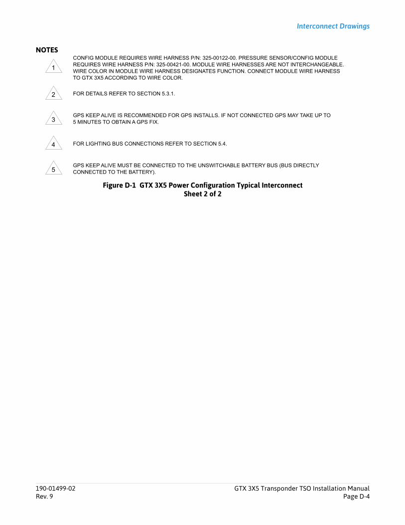
Interconnect Drawings
NOTES
Figure D-1 GTX 3X5 Power Configuration Typical InterconnectSheet 2 of 2
CONFIG MODULE REQUIRES WIRE HARNESS P/N: 325-00122-00. PRESSURE SENSOR/CONFIG MODULE REQUIRES WIRE HARNESS P/N: 325-00421-00. MODULE WIRE HARNESSES ARE NOT INTERCHANGEABLE. WIRE COLOR IN MODULE WIRE HARNESS DESIGNATES FUNCTION. CONNECT MODULE WIRE HARNESS TO GTX 3X5 ACCORDING TO WIRE COLOR.
FOR DETAILS REFER TO SECTION 5.3.1.
GPS KEEP ALIVE IS RECOMMENDED FOR GPS INSTALLS. IF NOT CONNECTED GPS MAY TAKE UP TO 5 MINUTES TO OBTAIN A GPS FIX.
FOR LIGHTING BUS CONNECTIONS REFER TO SECTION 5.4.
GPS KEEP ALIVE MUST BE CONNECTED TO THE UNSWITCHABLE BATTERY BUS (BUS DIRECTLY CONNECTED TO THE BATTERY).
1
2
3
4
5
190-01499-02 GTX 3X5 Transponder TSO Installation ManualRev. 9 Page D-4

Interconnect Drawings
Figure D-2 GTX 345 - G1000 InterconnectSheet 1 of 2
P3251GTX 345 XPDR
AIRCRAFT POWER AVIONICS BUS (28VDC or 14 VDC)
213A
GIA 63 #11P603
S
5355
54
AUDIO IN HIAUDIO IN LO
GMA 134746AUDIO OUT HI47AUDIO OUT LO
AIRCRAFT POWER 42
30RS-232 RX 2RS-232 TX 2 8
51RS-232 GND 2
RS-232 TX 5RS-232 RX 5SIGNAL GROUND
GIA 63 #22P603
S
5355
54
31RS-232 RX 1RS-232 TX 1 9
52RS-232 GND 1
RS-232 TX 5RS-232 RX 5RS-232 GND 5
3919
S
P3471
S
S
18s
EXTERNAL SUPPRESSION 1
RS-232 RX 86463
RS-232 GND 8S
5
P3252
15RS-232 TX 4
RS-232 GND 4
RS-422 Port 3ARS-422 Port 3B28
27
S
1112
RS-422 ARS-422 B
S
S
A429 TX 3A7475
A429 TX 3BS
4849
A429 RX 2AA429 RX 2B
S
2
CONFIG MODULE PWRCONFIG MODULE GND
CONFIG MODULE DATACONFIG MODULE CLK
4323221
RED
YELBLK
WHT
CONFIG MODULE
4
GTS 8XXP8001
S
2423
25
A429 TX 2AA429 TX 2BA429 RX 2A
27285
S
OPERATE/STANDBYSELF TEST SELECT
15CONFIG DISC 116CONFIG DISC 2 74
75
A429 RX 2B26
A429 RX 1AA429 RX 1BA429 TX 1AA429 TX 1B 6
S S
P8002
EXTERNAL SUPPRESSION
48s
6
5
7
AIRCRAFT GND 20AIRCRAFT GND 41
AIRCRAFTGROUND
POWER CONTROL 383 POWER CONFIG 59
190-01499-02 GTX 3X5 Transponder TSO Installation ManualRev. 9 Page D-5
Interconnect Drawings
NOTES
Figure D-2 GTX 345 - G1000 InterconnectSheet 2 of 2
CONNECTION TO AIRCRAFT SUPPRESSION BUS.
GDL 90 EMULATION - RS-422 FIS-B CONNECTION AND RS-232 ADS-B IN TRAFFIC.
REFER TO SECTION 5.3.1.
PROVIDES TRUE HEADING TO UNIT. USE ANY AVAILABLE ARINC 429 PORT. THIS MUST BE CONFIGURED BY THE INSTALLER.
GTS 8XX SHOWN AS AN EXAMPLE, FOR ALTERNATE EXTERNAL TRAFFIC SYSTEM OPTIONS, REFER TO EXTERNAL TRAFFIC SENSORS.
GTX 345 PROVIDES AUTOMATIC CONTROL OF OPERATE/STANDBY BASED ON AIRBORNE STATUS. GTX 3X5 INSTALL TOOL PROVIDES TRAFFIC SELF TEST DISCRETE FOR EXTERNAL TRAFFIC VALIDATION.
THIS DIAGRAM PROVIDES AN OVERVIEW OF A TYPICAL INSTALLATION. FOR SPECIFIC EQUIPMENT, REFER TO APPLICABLE INTERCONNECT DIAGRAMS.
1
2
3
4
5
6
7
190-01499-02 GTX 3X5 Transponder TSO Installation ManualRev. 9 Page D-6
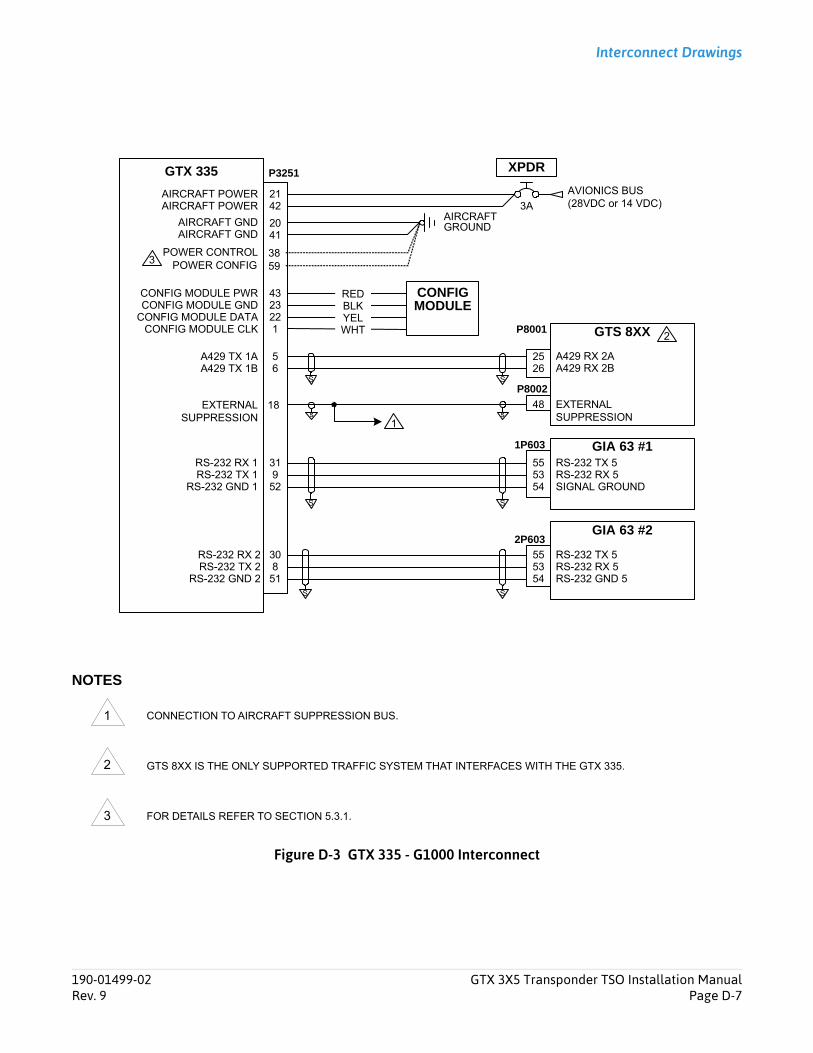
Interconnect Drawings
NOTES
Figure D-3 GTX 335 - G1000 Interconnect
CONNECTION TO AIRCRAFT SUPPRESSION BUS.
GTS 8XX IS THE ONLY SUPPORTED TRAFFIC SYSTEM THAT INTERFACES WITH THE GTX 335.
FOR DETAILS REFER TO SECTION 5.3.1.
P3251GTX 335 XPDR
AIRCRAFT POWER AVIONICS BUS (28VDC or 14 VDC)
213A
GIA 63 #11P603
S
5355
54
AIRCRAFT POWER 42
30RS-232 RX 2RS-232 TX 2 8
51RS-232 GND 2
RS-232 TX 5RS-232 RX 5SIGNAL GROUND
GIA 63 #22P603
S
5355
54
31RS-232 RX 1RS-232 TX 1 9
52RS-232 GND 1
RS-232 TX 5RS-232 RX 5RS-232 GND 5
S
S
18s
EXTERNAL SUPPRESSION 1
CONFIG MODULE PWRCONFIG MODULE GND
CONFIG MODULE DATACONFIG MODULE CLK
4323221
RED
YELBLK
WHT
CONFIG MODULE
GTS 8XXP8001
S
25 A429 RX 2A5
SA429 RX 2B26
A429 TX 1AA429 TX 1B 6
P8002
EXTERNAL SUPPRESSION
48s
2
AIRCRAFT GND 20AIRCRAFT GND 41
AIRCRAFTGROUND
POWER CONTROL 383 POWER CONFIG 59
1
2
3
190-01499-02 GTX 3X5 Transponder TSO Installation ManualRev. 9 Page D-7
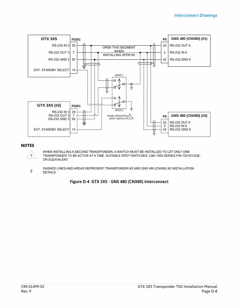
Interconnect Drawings
NOTES
Figure D-4 GTX 3X5 - GNS 480 (CNX80) Interconnect
WHEN INSTALLING A SECOND TRANSPONDER, A SWITCH MUST BE INSTALLED TO LET ONLY ONE TRANSPONDER TO BE ACTIVE AT A TIME. SUITABLE DPDT SWITCHES: C&K 7000 SERIES P/N 7201SYZQE, OR EQUIVALENT.
DASHED LINES AND AREAS REPRESENT TRANSPONDER #2 AND GNS 480 (CNX80) #2 INSTALLATION DETAILS.
GNS 480 (CNX80) (#1)P5GTX 3X5
2
22
42
29RS-232 IN 3
RS-232 OUT 3 7
50RS-232 GND 3
RS-232 OUT 6
RS-232 IN 6
RS-232 GND 6
S
GTX 3X5 (#2)
29RS-232 IN 3RS-232 OUT 3 7
50RS-232 GND 3GNS 480 (CNX80) (#2)
222
42
RS-232 OUT 6RS-232 IN 6RS-232 GND 6
1PANEL MOUNTEDDPDT SWITCH
XPDR 1
XPDR 2
14EXT. STANDBY SELECT
14EXT. STANDBY SELECT
S
OPEN THIS SEGMENT WHEN
INSTALLING XPDR #2
P3251
P5
P3251
1
2
190-01499-02 GTX 3X5 Transponder TSO Installation ManualRev. 9 Page D-8
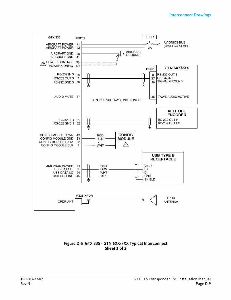
Interconnect Drawings
Figure D-5 GTX 335 - GTN 6XX/7XX Typical InterconnectSheet 1 of 2
GTX 335
AIRCRAFT POWER 21
GTN 6XX/7XXP1001
278
46
AIRCRAFT POWER 42
TAWS AUDIO ACTIVE3537AUDIO MUTEGTN 6XX/7XX TAWS UNITS ONLY
29RS-232 IN 3RS-232 OUT 3 7
50RS-232 GND 3
RS-232 OUT 1RS-232 IN 1SIGNAL GROUND
P3251 XPDR
AVIONICS BUS (28VDC or 14 VDC)3A
XPDR ANTXPDR
ANTENNA
P325-XPDR
CONFIG MODULE PWRCONFIG MODULE GND
CONFIG MODULE DATACONFIG MODULE CLK
4323221
USB VBUS POWERUSB DATA HI
USB DATA LOUSB GROUND
4422445
s
RED
YELBLK
WHT
REDGRN
BLKWHT
USB TYPE BRECEPTACLE
CONFIG MODULE
1
VBUSD+D-GNDSHIELD
RS-232 OUT HIRS-232 OUT LO
ALTITUDE ENCODER
31RS-232 IN 152RS-232 GND 1
S
S
AIRCRAFT GND 20AIRCRAFT GND 41
AIRCRAFTGROUND
POWER CONTROL 382 POWER CONFIG 59
190-01499-02 GTX 3X5 Transponder TSO Installation ManualRev. 9 Page D-9
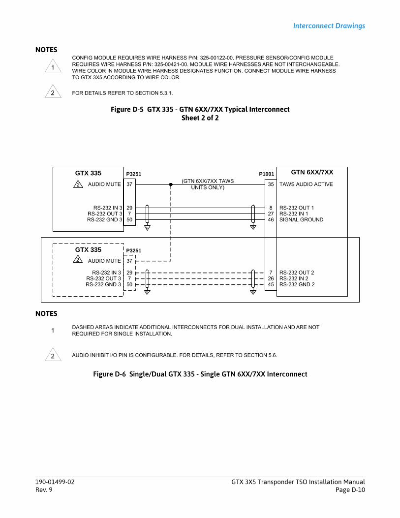
Interconnect Drawings
NOTES
Figure D-5 GTX 335 - GTN 6XX/7XX Typical InterconnectSheet 2 of 2
NOTES
Figure D-6 Single/Dual GTX 335 - Single GTN 6XX/7XX Interconnect
CONFIG MODULE REQUIRES WIRE HARNESS P/N: 325-00122-00. PRESSURE SENSOR/CONFIG MODULE REQUIRES WIRE HARNESS P/N: 325-00421-00. MODULE WIRE HARNESSES ARE NOT INTERCHANGEABLE. WIRE COLOR IN MODULE WIRE HARNESS DESIGNATES FUNCTION. CONNECT MODULE WIRE HARNESS TO GTX 3X5 ACCORDING TO WIRE COLOR.
FOR DETAILS REFER TO SECTION 5.3.1.
DASHED AREAS INDICATE ADDITIONAL INTERCONNECTS FOR DUAL INSTALLATION AND ARE NOT REQUIRED FOR SINGLE INSTALLATION.
AUDIO INHIBIT I/O PIN IS CONFIGURABLE. FOR DETAILS, REFER TO SECTION 5.6.
1
2
GTN 6XX/7XXGTX 335
278
46
29RS-232 IN 3RS-232 OUT 3 7
50RS-232 GND 3
RS-232 OUT 1RS-232 IN 1SIGNAL GROUND
s
P1001
TAWS AUDIO ACTIVE3537AUDIO MUTE
GTX 335
29RS-232 IN 3RS-232 OUT 3 7
50RS-232 GND 3
37AUDIO MUTE
7RS-232 IN 2RS-232 OUT 2
2645 RS-232 GND 2
s
P3251
P3251
(GTN 6XX/7XX TAWSUNITS ONLY)
s
s
2
2
1
2
190-01499-02 GTX 3X5 Transponder TSO Installation ManualRev. 9 Page D-10

Interconnect Drawings
Figure D-7 GTX 345 - GTN 6XX/7XX Typical InterconnectSheet 1 of 2
GTX 345
CONFIG MODULE PWRCONFIG MODULE GND
CONFIG MODULE DATACONFIG MODULE CLK
4323221
GTN 6XX/7XXP1002
27
61
ETHERNET IN 1A
ETHERNET OUT 1AETHERNET IN 1B
ETHERNET OUT 1B
s s
ETHERNET OUT 3A
ETHERNET IN 3AETHERNET OUT 3B
ETHERNET IN 3B
2625
2324
P1001
TAWS AUDIO ACTIVE3537AUDIO MUTE
29RS-232 IN 3RS-232 OUT 3 7
50RS-232 GND 3
RS-232 OUT 1RS-232 IN 1
s
SIGNAL GROUND278
46
P3251
P3252
s
RS-232 OUT HIRS-232 OUT LO
ALTITUDE ENCODER
AUDIO IN HIAUDIO IN LO
AUDIO PANEL
31RS-232 IN 152RS-232 GND 1
s
46AUDIO OUT HI47AUDIO OUT LO
AIRCRAFT POWER 21AIRCRAFT POWER 42
XPDR
AVIONICS BUS (28VDC or 14 VDC)
22 AWG3A22 AWG
XPDR ANTXPDR
ANTENNA
P325-XPDR
CONFIG MODULE
1
USB VBUS POWERUSB DATA HI
USB DATA LOUSB GROUND
4422445
s
VBUSD+D-GNDSHIELD
REDGRN
BLKWHT
USB TYPE BRECEPTACLE
RED
YELBLK
WHT
2
s
18EXT SUPPRESSION A/C SUPPRESSION BUS
AIRCRAFT GND 20AIRCRAFT GND 41
AIRCRAFTGROUND
POWER CONTROL 38POWER CONFIG 59
190-01499-02 GTX 3X5 Transponder TSO Installation ManualRev. 9 Page D-11

Interconnect Drawings
NOTES
Figure D-7 GTX 345 - GTN 6XX/7XX Typical InterconnectSheet 2 of 2
CONFIG MODULE REQUIRES WIRE HARNESS P/N: 325-00122-00. PRESSURE SENSOR/CONFIG MODULE REQUIRES WIRE HARNESS P/N: 325-00421-00. MODULE WIRE HARNESSES ARE NOT INTERCHANGEABLE. WIRE COLOR IN MODULE WIRE HARNESS DESIGNATES FUNCTION. CONNECT MODULE WIRE HARNESS TO GTX 3X5 ACCORDING TO WIRE COLOR.
FOR DETAILS REFER TO SECTION 5.3.1.
1
2
190-01499-02 GTX 3X5 Transponder TSO Installation ManualRev. 9 Page D-12
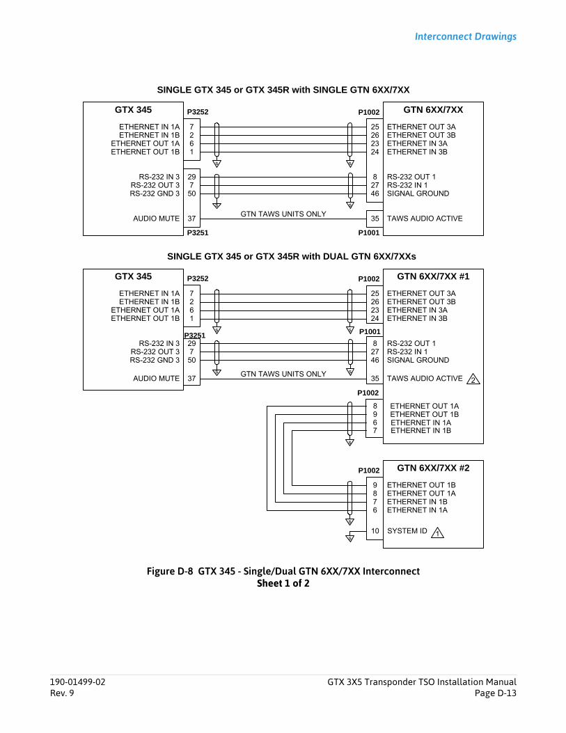
Interconnect Drawings
Figure D-8 GTX 345 - Single/Dual GTN 6XX/7XX InterconnectSheet 1 of 2
GTX 345 GTN 6XX/7XX #1
ETHERNET OUT 1A
ETHERNET IN 1AETHERNET OUT 1B
ETHERNET IN 1B
98
67
GTN 6XX/7XX #2P1002
ETHERNET OUT 1B
ETHERNET IN 1BETHERNET OUT 1A
ETHERNET IN 1A
89
76
SYSTEM ID10s
SINGLE GTX 345 or GTX 345R with DUAL GTN 6XX/7XXs
GTN 6XX/7XXGTX 345
SINGLE GTX 345 or GTX 345R with SINGLE GTN 6XX/7XX
P1002
27
61
ETHERNET IN 1A
ETHERNET OUT 1AETHERNET IN 1B
ETHERNET OUT 1B
s s
ETHERNET OUT 3A
ETHERNET IN 3AETHERNET OUT 3B
ETHERNET IN 3B
2625
2324
P1001
TAWS AUDIO ACTIVE3537AUDIO MUTEGTN TAWS UNITS ONLY
29RS-232 IN 3RS-232 OUT 3 7
50RS-232 GND 3
RS-232 OUT 1RS-232 IN 1
s
SIGNAL GROUND278
46
P3251
P3252
P1001
s
P1002
27
61
ETHERNET IN 1A
ETHERNET OUT 1AETHERNET IN 1B
ETHERNET OUT 1B
s s
ETHERNET OUT 3A
ETHERNET IN 3AETHERNET OUT 3B
ETHERNET IN 3B
2625
2324
TAWS AUDIO ACTIVE3537AUDIO MUTEGTN TAWS UNITS ONLY
29RS-232 IN 3RS-232 OUT 3 7
50RS-232 GND 3
RS-232 OUT 1RS-232 IN 1
s
SIGNAL GROUND278
46
P3251
P3252
s
s
s
1
2
P1002
190-01499-02 GTX 3X5 Transponder TSO Installation ManualRev. 9 Page D-13
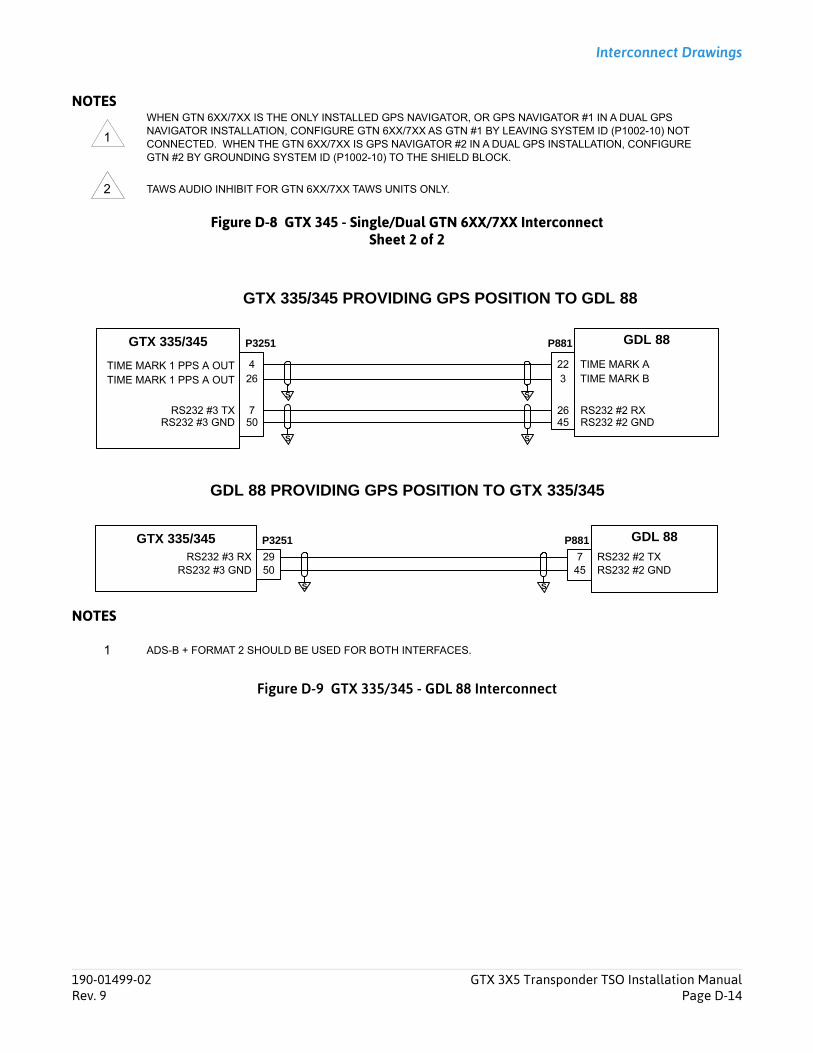
Interconnect Drawings
NOTES
Figure D-8 GTX 345 - Single/Dual GTN 6XX/7XX InterconnectSheet 2 of 2
NOTES
Figure D-9 GTX 335/345 - GDL 88 Interconnect
WHEN GTN 6XX/7XX IS THE ONLY INSTALLED GPS NAVIGATOR, OR GPS NAVIGATOR #1 IN A DUAL GPS NAVIGATOR INSTALLATION, CONFIGURE GTN 6XX/7XX AS GTN #1 BY LEAVING SYSTEM ID (P1002-10) NOT CONNECTED. WHEN THE GTN 6XX/7XX IS GPS NAVIGATOR #2 IN A DUAL GPS INSTALLATION, CONFIGURE GTN #2 BY GROUNDING SYSTEM ID (P1002-10) TO THE SHIELD BLOCK.
TAWS AUDIO INHIBIT FOR GTN 6XX/7XX TAWS UNITS ONLY.
ADS-B + FORMAT 2 SHOULD BE USED FOR BOTH INTERFACES.
1
2
GTX 335/345 GDL 88P3251
TIME MARK A
RS232 #2 GND
4 22
RS232 #2 RX 4526
507
RS232 #3 GND RS232 #3 TX
P881
TIME MARK 1 PPS A OUT
S S
GTX 335/345 PROVIDING GPS POSITION TO GDL 88
GDL 88 PROVIDING GPS POSITION TO GTX 335/345
GTX 335/345 GDL 88P3251
RS232 #2 TX RS232 #2 GND 45
75029RS232 #3 RX
RS232 #3 GND
P881
S S
TIME MARK B26 3TIME MARK 1 PPS A OUTSS
1
190-01499-02 GTX 3X5 Transponder TSO Installation ManualRev. 9 Page D-14
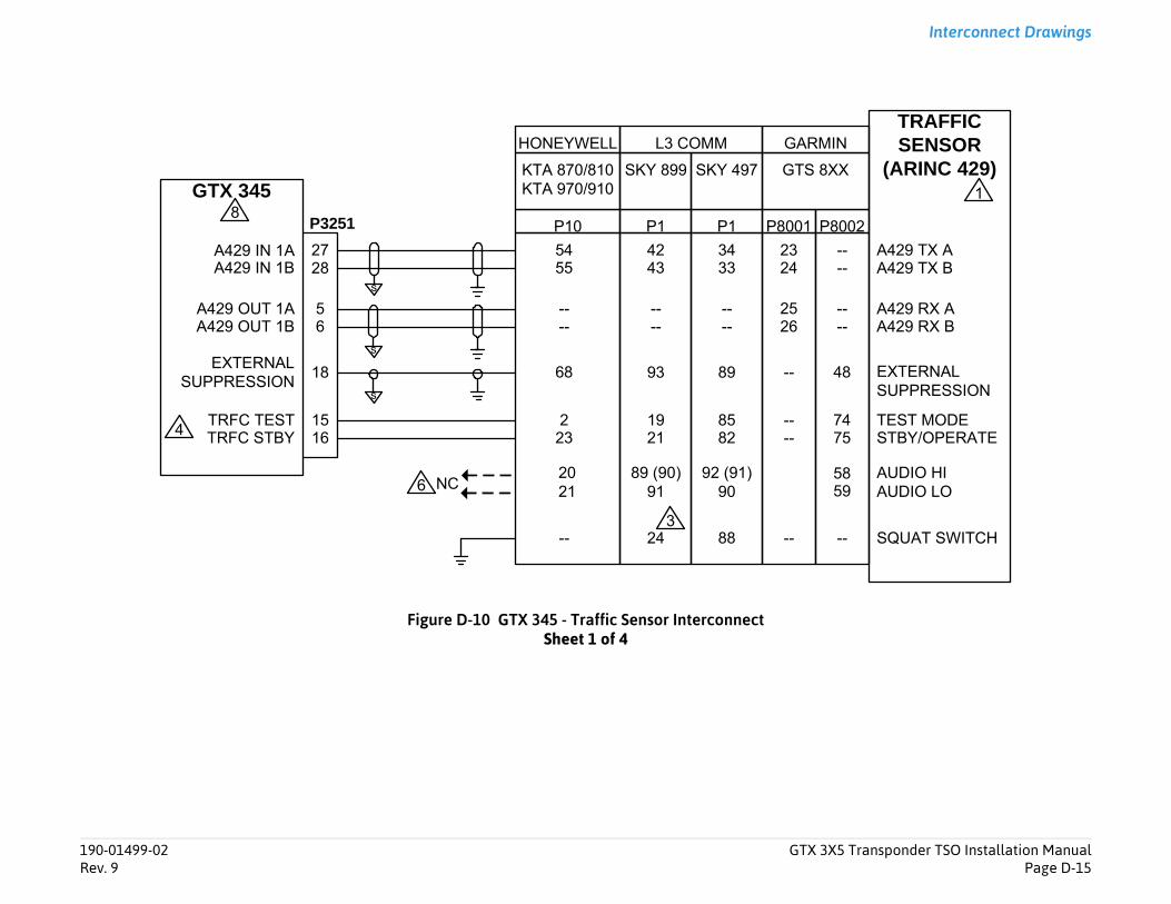
Transponder TSO Installation ManualPage D-15
Interconnect Drawings
-- A429 TX B
A429 TX A
TRAFFICSENSOR
(ARINC 429)
-- A429 RX B
A429 RX A
8 EXTERNALSUPPRESSION
1
STBY/OPERATETEST MODE4
5
02
SQUAT SWITCH-
AUDIO HIAUDIO LO9
8
190-01499-02 GTX 3X5Rev. 9
Figure D-10 GTX 345 - Traffic Sensor InterconnectSheet 1 of 4
GTX 345
P3251
A429 IN 1BA429 IN 1A
2827
s
GTS 8XX
--
SKY 497
3433
SKY 899
4243
----
--
----A429 OUT 1B
A429 OUT 1A65
418 8993s
EXTERNALSUPPRESSION
5455
----
68
TRFC TEST 15TRFC STBY 16
223
858221
19 77
P80P8001
2324
2526
--
----
P1P1
GARMINL3 COMMHONEYWELL
P10
KTA 870/810KTA 970/910
4
s
8824 --- --3
62021
89 (90)91
92 (91)90 5
5
8
NC

Interconnect Drawings
Figure D-10 GTX 345 - Traffic Sensor InterconnectSheet 2 of 4
GTX 345
P3251
A429 IN 1BA429 IN 1A
2827
A429 TX BA429 TX A
TRAFFICSENSOR
(ARINC 429)
EXTERNALSUPPRESSION
18s
EXTERNALSUPPRESSION
5455
68
TRFC TEST 15TRFC STBY 16
223 STBY/OPERATE
TEST MODE
HONEYWELL
P10
KMH 820/880KMH 920/980
s
AUDIO MUTE 58
OTHER ALERTINGSYSTEMS
TERRAINANNUNCIATOR(S)
116117
22
2021 AUDIO LOW
AUDIO HIGHEXISTING WIRING TO AUDIO PANEL
ADV INHIBIT
TERRAIN WARNTERRAIN CAUTION
8
4
1
9
2
190-01499-02 GTX 3X5 Transponder TSO Installation ManualRev. 9 Page D-16
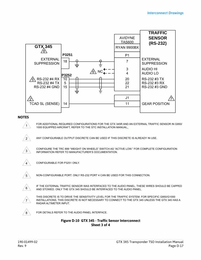
Interconnect Drawings
NOTES
Figure D-10 GTX 345 - Traffic Sensor InterconnectSheet 3 of 4
FOR ADDITIONAL REQUIRED CONFIGURATIONS FOR THE GTX 345R AND AN EXTERNAL TRAFFIC SENSOR IN G950/1000 EQUIPPED AIRCRAFT, REFER TO THE STC INSTALLATION MANUAL.
ANY CONFIGURABLE OUTPUT DISCRETE CAN BE USED IF THIS DISCRETE IS ALREADY IN USE.
CONFIGURE THE TRC 899 “WEIGHT ON WHEELS” SWITCH AS “ACTIVE LOW.” FOR COMPLETE CONFIGURATION INFORMATION REFER TO MANUFACTURER’S DOCUMENTATION.
CONFIGURABLE FOR P3251 ONLY.
NON-CONFIGURABLE PORT. ONLY RS-232 PORT 4 CAN BE USED FOR THIS CONNECTION.
IF THE EXTERNAL TRAFFIC SENSOR WAS INTERFACED TO THE AUDIO PANEL, THESE WIRES SHOULD BE CAPPED AND STOWED. ONLY THE GTX 345 SHOULD BE INTERFACED TO THE AUDIO PANEL.
THIS DISCRETE IS TO DRIVE THE SENSITIVITY LEVEL FOR THE TRAFFIC SYSTEM. FOR SPECIFIC G950/G1000 INSTALLATIONS, THIS DISCRETE IS NOT NECESSARY TO CONNECT TO THE GTX 345 UNLESS THE GTX 345 HAS A RADAR ALTIMETER INPUT.
FOR DETAILS REFER TO THE AUDIO PANEL INTERFACE.
GTX 345
P3252
RS-232 #4 TXRS-232 #4 RX
510
s
2022 RS-232 #3 RX
RS-232 #3 TX
TRAFFICSENSOR(RS-232)
RS-232 #3 GND21RS-232 #4 GND 15
7EXTERNALSUPPRESSION
18s
EXTERNALSUPPRESSION
P3251
14TCAD SL (SENSE) 11 GEAR POSITION
AVIDYNETAS600
RYAN 9900BX
P1
2
5
J1
6
7
AUDIO HIAUDIO LO
34
8
NC
1
2
3
4
5
6
7
8
190-01499-02 GTX 3X5 Transponder TSO Installation ManualRev. 9 Page D-17
Interconnect Drawings
Figure D-10 GTX 345 - Traffic Sensor InterconnectSheet 4 of 4
IF THE KMH HAS THE COMBINED TAS/EGPWS, THE AUDIO WIRING REMAINS CONNECTED. THE TERRAIN ANNUNCIATOR SIGNALS DRIVE THE AUDIO MUTE INPUT TO THE GTX WITH THE APPLICATION OF TWO ADDITIONAL DIODES, P/N: 1N4007. IF OTHER SYSTEMS INTERFACE TO THE ADV INHIBIT (P10-22), THEY SHOULD BE REMOVED FROM P100-22 AND INTERFACED TO THE GTX AS SHOWN. IF THE EGPWS IS NOT ENABLED, THE AUDIO WIRING CAN BE CAPPED AND STOWED AND THE TERRAIN ANNUNCIATOR SIGNALS WITH THE DIODES DO NOT NEED TO BE CONNECTED TO THE GTX AUDIO MUTE.
9
190-01499-02 GTX 3X5 Transponder TSO Installation ManualRev. 9 Page D-18
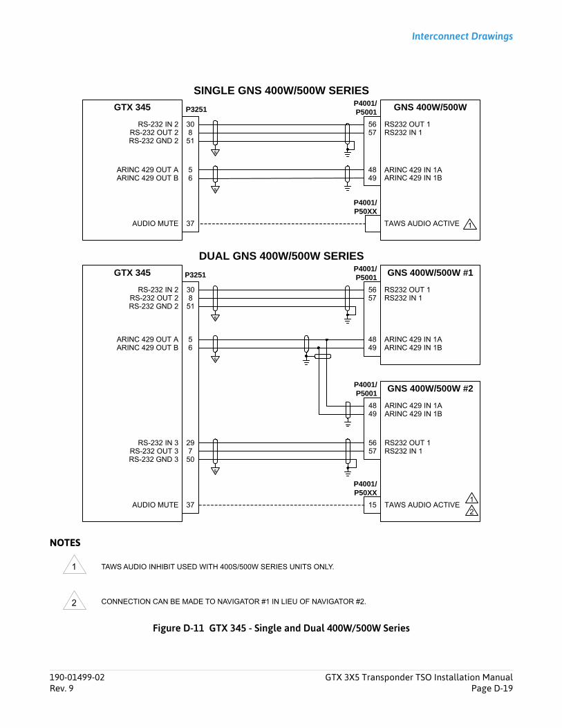
Interconnect Drawings
NOTES
Figure D-11 GTX 345 - Single and Dual 400W/500W Series
TAWS AUDIO INHIBIT USED WITH 400S/500W SERIES UNITS ONLY.
CONNECTION CAN BE MADE TO NAVIGATOR #1 IN LIEU OF NAVIGATOR #2.
GNS 400W/500WP4001/P5001
GTX 345
DUAL GNS 400W/500W SERIES
RS232 OUT 1RS232 IN 1
5657
30RS-232 IN 2RS-232 OUT 2 8
51RS-232 GND 2
GNS 400W/500W #1P4001/P5001
GTX 345
ARINC 429 IN 1AARINC 429 IN 1B
4849
5ARINC 429 OUT A6ARINC 429 OUT B
GNS 400W/500W #2P4001/P5001
RS232 OUT 1RS232 IN 1
5657
29RS-232 IN 3RS-232 OUT 3 7
50RS-232 GND 3
ARINC 429 IN 1AARINC 429 IN 1B
4849
RS232 OUT 1RS232 IN 1
5657
30RS-232 IN 2RS-232 OUT 2 8
51RS-232 GND 2
ARINC 429 IN 1AARINC 429 IN 1B
4849
5ARINC 429 OUT A6ARINC 429 OUT B
TAWS AUDIO ACTIVE37AUDIO MUTE
SINGLE GNS 400W/500W SERIES
TAWS AUDIO ACTIVE37
P4001/P50XX
AUDIO MUTE
P3251
P3251
s
s
s
s
s
P4001/P50XX
1
1
215
1
2
190-01499-02 GTX 3X5 Transponder TSO Installation ManualRev. 9 Page D-19

Interconnect Drawings
NOTES
Figure D-12 GTX 3X5 - Audio Interconnect
SEE THE GENERAL NOTES IDENTIFIED AT THE BEGINNING OF THIS APPENDIX FOR ADDITIONAL DETAILS AND REQUIREMENTS.
IT IS ACCEPTABLE TO USE OTHER AVAILABLE UNSWITCHED, UNMUTED INPUTS. IF AUDIO PANEL DOES NOT HAVE AN AVAILABLE UNSWITCHED, UNMUTED INPUT, AUDIO FROM THE GTX 3X5 MUST BE MIXED WITH AN EXISTING AUDIO SOURCE USING RESISTORS TO ISOLATE THE AUDIO OUTPUT FROM EACH LRU. A TYPICAL VALUE FOR MIXING RESISTORS IS 390Ω ¼ W.
THE AUDIO LEVELS OF EXISTING AUDIO SOURCES WILL HAVE TO BE RE-EVALUATED AFTER MIXING RESISTORS ARE INSTALLED. SHIELDS FOR AUDIO CABLES SHOULD BE GROUNDED AT ONE END (WITH LEADS LESS THAN 3.0 INCHES) AND LEFT FLOATING AT THE OTHER END.
GARMIN
SL 10/15 SERIES
BOTTOM
GMA 340 GMA 347GMA 35GMA 350
J1 P3471 P3501
GTX 3X5
P3251
AUDIO OUT HIAUDIO OUT LO
AUDIO MUTE
4647
37
3231
GND LUGT
3919
3231
AUDIOPANEL
(ANALOG)
AUDIO IN [LO]AUDIO IN [HI]
EXTERNAL AUDIO INHIBIT DISCRETE (GND) – CONNECT TO HIGH PRIORITY DEVICES (TAWS, ETC.)
PS ENGINEERINGBENDIX/KING
PMA 8000PMA 6000PMA 7000
KMA 24 KMA 26 KMA 28KMA 24H
-70/-71
J1 (Bottom) BOTTOMP241 P261 J1(Bottom)P241
GTX 3X5
P3251
AUDIO OUT HIAUDIO OUT LO
AUDIO MUTE
4647
37
GND LUGT 14
31 GND LUGT
1410
3231
GND LUGT
AUDIOPANEL
(ANALOG)
AUDIO IN [LO]AUDIO IN [HI]
EXTERNAL AUDIO INHIBIT DISCRETE (GND) – CONNECT TO HIGH PRIORITY DEVICES (TAWS, ETC.)
2
2
3
3
1
2
3
190-01499-02 GTX 3X5 Transponder TSO Installation ManualRev. 9 Page D-20
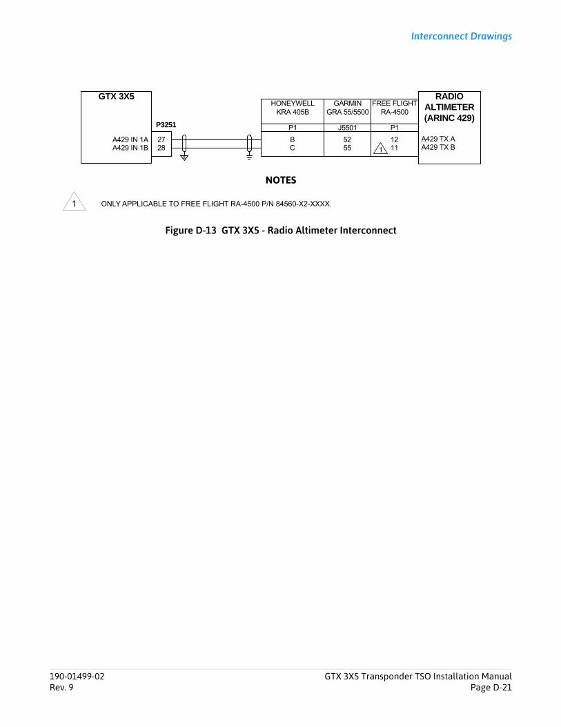
Interconnect Drawings
NOTES
Figure D-13 GTX 3X5 - Radio Altimeter Interconnect
ONLY APPLICABLE TO FREE FLIGHT RA-4500 P/N 84560-X2-XXXX.
GTX 3X5
P3251
A429 IN 1BA429 IN 1A
2827
s
FREE FLIGHTRA-4500
1211
GARMINGRA 55/5500
5255
HONEYWELLKRA 405B
BC A429 TX B
A429 TX A
RADIOALTIMETER(ARINC 429)
P1 J5501 P1
1
1
190-01499-02 GTX 3X5 Transponder TSO Installation ManualRev. 9 Page D-21
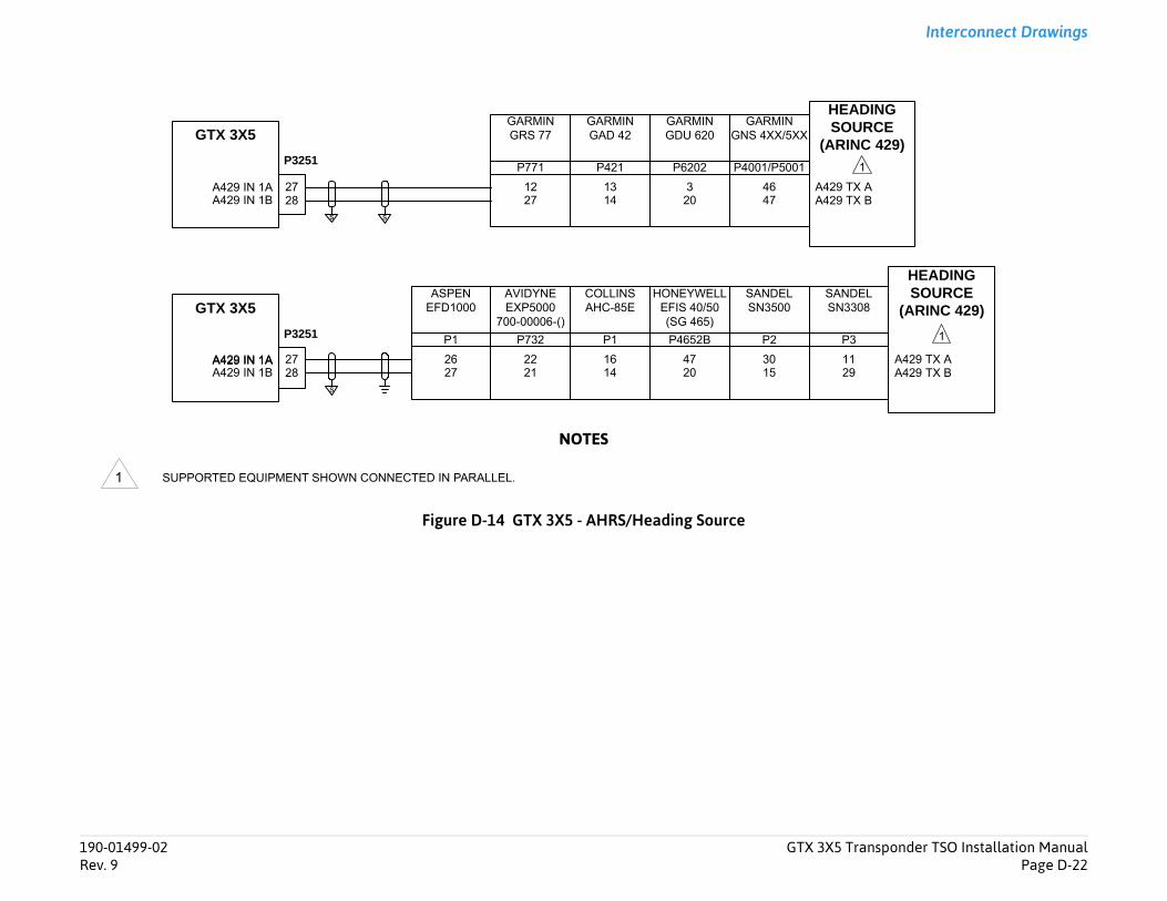
Transponder TSO Installation ManualPage D-22
Interconnect Drawings
9 TX B9 TX A
EADINGOURCEINC 429)
1
A429 TX BA429 TX A
HEADINGSOURCE
(ARINC 429)NDEL3308
1129
P3
1
190-01499-02 GTX 3X5Rev. 9
NOTES
Figure D-14 GTX 3X5 - AHRS/Heading Source
SUPPORTED EQUIPMENT SHOWN CONNECTED IN PARALLEL.
GTX 3X5
P3251
A429 IN 1BA429 IN 1A
2827
s
GARMINGDU 620
320
GARMINGAD 42
1314 A42
A42
HS
(AR
GARMINGRS 77
1227
HONEYWELLEFIS 40/50(SG 465)
4720
COLLINSAHC-85E
1614
AVIDYNEEXP5000
700-00006-()
2221
ASPENEFD1000
2627
SASN
SANDELSN3500
3015
P1 P1 P2P4652BP732
P771 P421 P6202
A429 IN 1BA429 IN 1A
2827
s s
GTX 3X5
P3251
A429 IN 1A
GARMINGNS 4XX/5XX
4647
P4001/P5001
1
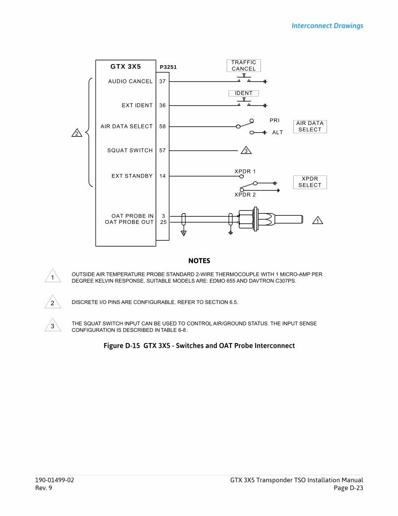
Interconnect Drawings
NOTES
Figure D-15 GTX 3X5 - Switches and OAT Probe Interconnect
OUTSIDE AIR TEMPERATURE PROBE STANDARD 2-WIRE THERMOCOUPLE WITH 1 MICRO-AMP PER DEGREE KELVIN RESPONSE. SUITABLE MODELS ARE: EDMO 655 AND DAVTRON C307PS.
DISCRETE I/O PINS ARE CONFIGURABLE. REFER TO SECTION 6.5.
THE SQUAT SWITCH INPUT CAN BE USED TO CONTROL AIR/GROUND STATUS. THE INPUT SENSE CONFIGURATION IS DESCRIBED IN TABLE 6-8 .
GTX 3X5 P3251
37AUDIO CANCEL
TRAFFIC CANCEL
36EXT IDENT
IDENT
PRI58AIR DATA SELECT
AIR DATASELECT
SQUAT SWITCH 57
ALT
S
OAT PROBE INOAT PROBE OUT
325 1
2
3
XPDR 114EXT STANDBY
XPDR 2
XPDRSELECT
1
2
3
190-01499-02 GTX 3X5 Transponder TSO Installation ManualRev. 9 Page D-23
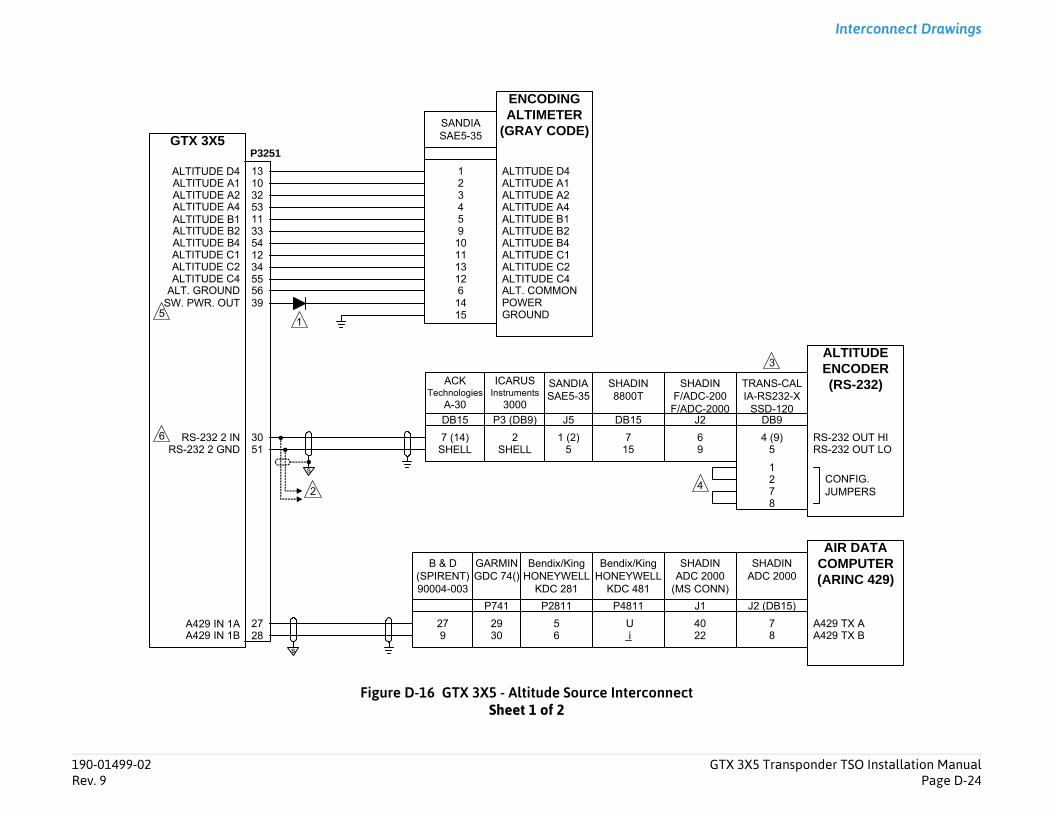
Transponder TSO Installation ManualPage D-24
Interconnect Drawings
RS-232 OUT LORS-232 OUT HI
ALTITUDEENCODER(RS-232)
A429 TX BA429 TX A
AIR DATA COMPUTER(ARINC 429)
ANS-CALRS232-XSD-120
4 (9)5
CONFIG.JUMPERS
1278
HADINDC 2000
78
3
DB9
(DB15)
190-01499-02 GTX 3X5Rev. 9
Figure D-16 GTX 3X5 - Altitude Source InterconnectSheet 1 of 2
P3251
SANDIASAE5-35
ALTITUDE A2ALTITUDE A4
ALTITUDE C4
ALTITUDE A1
ALTITUDE C1ALTITUDE C2
ALTITUDE B2ALTITUDE B4
ALTITUDE D4
ALTITUDE B1
ENCODING ALTIMETER
(GRAY CODE)
1
5910111312
234
15 GROUND
SANDIASAE5-35
1 (2)5
ICARUSInstruments
3000
2SHELL
s
SHADINADC 2000
(MS CONN)
4022
SHADIN8800T
715
ACKTechnologies
A-30
7 (14)SHELL
TRIA-
S
SHADINF/ADC-200F/ADC-2000
69
s
GARMINGDC 74()
2930
B & D(SPIRENT)90004-003
279
Bendix/KingHONEYWELL
KDC 481
U i
Bendix/KingHONEYWELL
KDC 281
56
14 POWER 1
SA
2 4
DB15 P3 (DB9) J5 DB15 J2
P741 P2811 P4811 J1 J2
GTX 3X5
ALTITUDE A2ALTITUDE A4
ALTITUDE C4
ALTITUDE A1
ALTITUDE C1ALTITUDE C2
ALTITUDE B2ALTITUDE B4
ALTITUDE D4
ALTITUDE B1
SW. PWR. OUT 39
533210
553412543311
13
A429 IN 1BA429 IN 1A
2827
RS-232 2 GNDRS-232 2 IN
5130
ALT. COMMON6ALT. GROUND 56
5
6
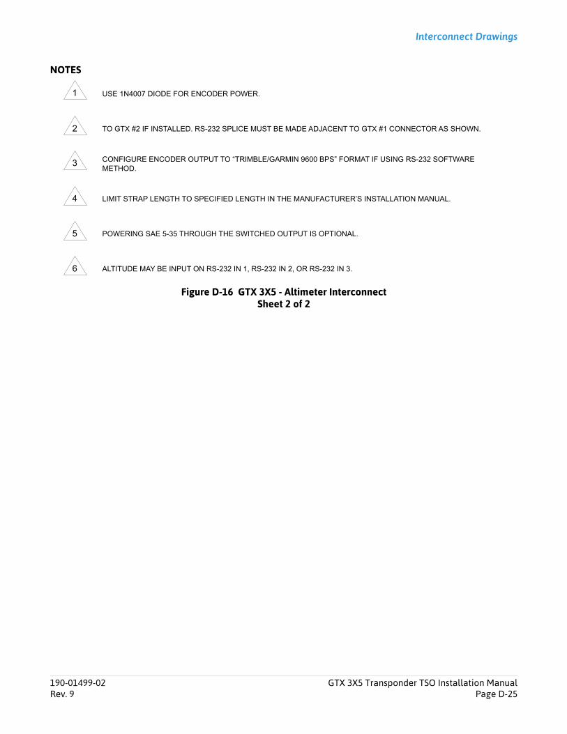
Interconnect Drawings
NOTES
Figure D-16 GTX 3X5 - Altimeter InterconnectSheet 2 of 2
USE 1N4007 DIODE FOR ENCODER POWER.
TO GTX #2 IF INSTALLED. RS-232 SPLICE MUST BE MADE ADJACENT TO GTX #1 CONNECTOR AS SHOWN.
CONFIGURE ENCODER OUTPUT TO “TRIMBLE/GARMIN 9600 BPS” FORMAT IF USING RS-232 SOFTWARE METHOD.
LIMIT STRAP LENGTH TO SPECIFIED LENGTH IN THE MANUFACTURER’S INSTALLATION MANUAL.
POWERING SAE 5-35 THROUGH THE SWITCHED OUTPUT IS OPTIONAL.
ALTITUDE MAY BE INPUT ON RS-232 IN 1, RS-232 IN 2, OR RS-232 IN 3.
1
2
3
4
5
6
190-01499-02 GTX 3X5 Transponder TSO Installation ManualRev. 9 Page D-25
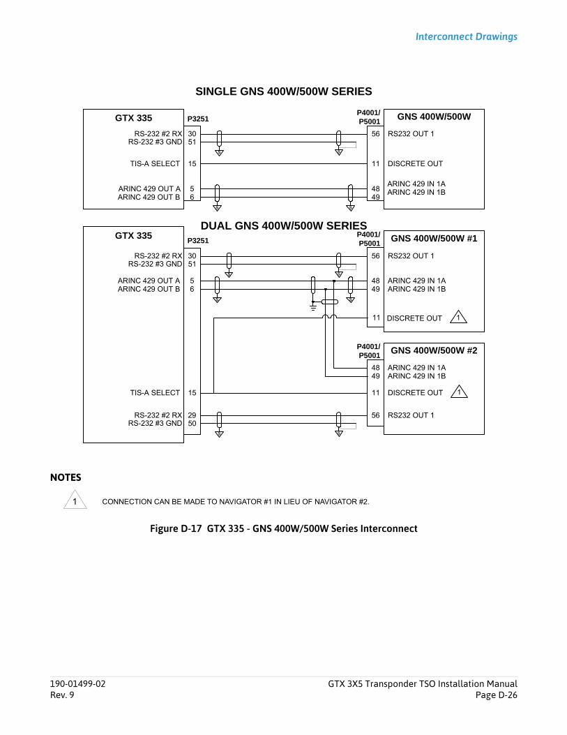
Interconnect Drawings
NOTES
Figure D-17 GTX 335 - GNS 400W/500W Series Interconnect
CONNECTION CAN BE MADE TO NAVIGATOR #1 IN LIEU OF NAVIGATOR #2.
GNS 400W/500WP4001/P5001GTX 335
DISCRETE OUT1115TIS-A SELECT
DUAL GNS 400W/500W SERIES
RS232 OUT 15630
GNS 400W/500W #1P4001/P5001
GTX 335
ARINC 429 IN 1AARINC 429 IN 1B
4849
5ARINC 429 OUT A6ARINC 429 OUT B
GNS 400W/500W #2P4001/P5001
ARINC 429 IN 1AARINC 429 IN 1B
4849
ARINC 429 IN 1AARINC 429 IN 1B48
495ARINC 429 OUT A6ARINC 429 OUT B
SINGLE GNS 400W/500W SERIES
P3251
P3251
s s
ss
DISCRETE OUT1115TIS-A SELECT 1
RS-232 #2 RX
s
RS-232 #3 GND 51s
RS232 OUT 15630RS-232 #2 RX
s
RS-232 #3 GND 51s
RS232 OUT 15629RS-232 #2 RX
s
RS-232 #3 GND 50s
11 DISCRETE OUT 1
1
190-01499-02 GTX 3X5 Transponder TSO Installation ManualRev. 9 Page D-26
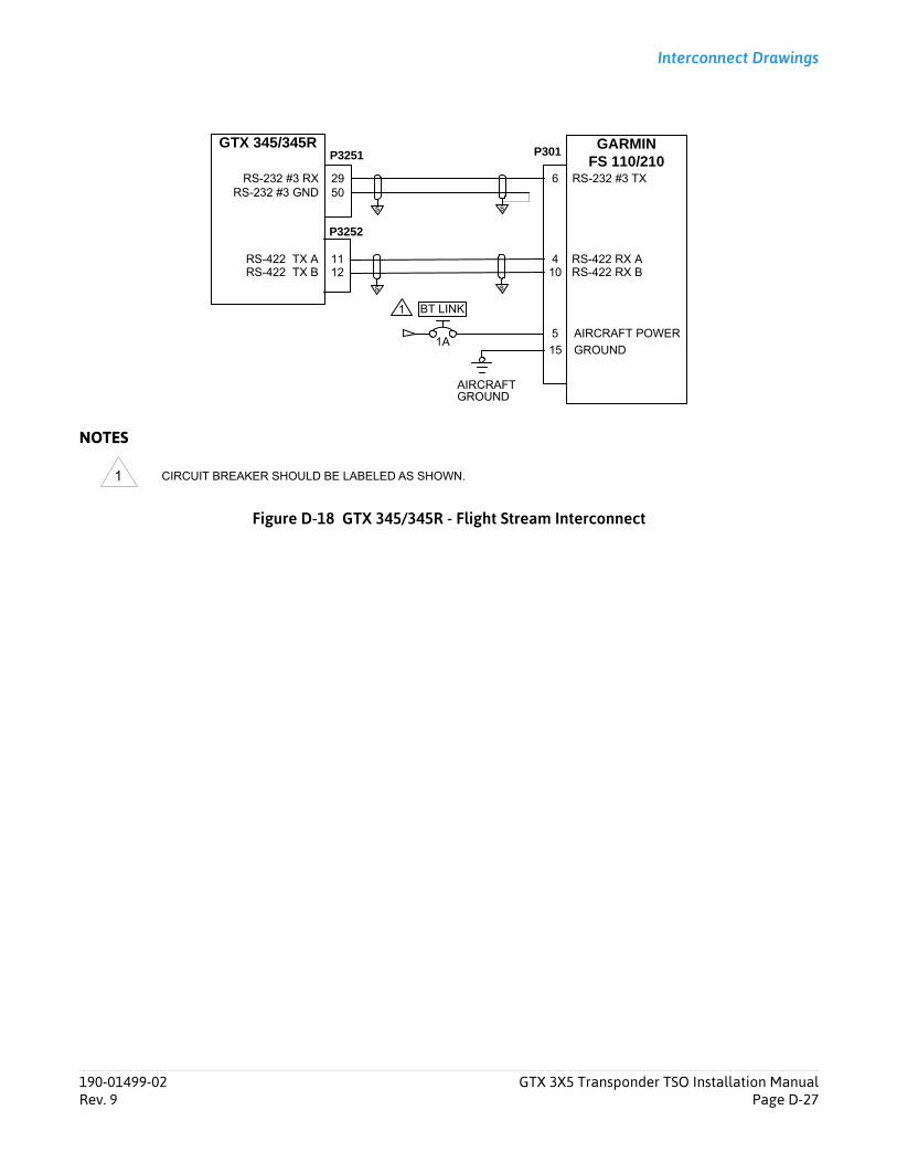
Interconnect Drawings
NOTES
Figure D-18 GTX 345/345R - Flight Stream Interconnect
CIRCUIT BREAKER SHOULD BE LABELED AS SHOWN.
GTX 345/345RP3251
RS-232 #3 RX 29
s
6 RS-232 #3 TX
GARMINFS 110/210
RS-232 #3 GND 50
RS-422 TX A 11
s
4 RS-422 RX ARS-422 RX B10RS-422 TX B 12
s
s
P3252
P301
5
15 GROUND
AIRCRAFT POWER
BT LINK
1A
AIRCRAFT GROUND
1
1
190-01499-02 GTX 3X5 Transponder TSO Installation ManualRev. 9 Page D-27
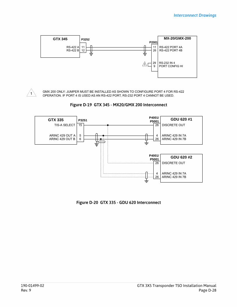
Interconnect Drawings
Figure D-19 GTX 345 - MX20/GMX 200 Interconnect
Figure D-20 GTX 335 - GDU 620 Interconnect
GMX 200 ONLY: JUMPER MUST BE INSTALLED AS SHOWN TO CONFIGURE PORT 4 FOR RS-422 OPERATION. IF PORT 4 IS USED AS AN RS-422 PORT, RS-232 PORT 4 CANNOT BE USED.
P3252GTX 345 MX-20/GMX-200
RS-422 PORT 4ARS-422 PORT 4B26
11
S
1112
RS-422 ARS-422 B
S
P2001
299
RS-232 IN 4PORT CONFIG HI
1
1
GDU 620 #1P4001/P5001GTX 335
DISCRETE OUT2615TIS-A SELECT
ARINC 429 IN 7AARINC 429 IN 7B
426
5ARINC 429 OUT A6ARINC 429 OUT B
P3251
s
GDU 620 #2P4001/P5001
DISCRETE OUT26
ARINC 429 IN 7AARINC 429 IN 7B
426
s
S
190-01499-02 GTX 3X5 Transponder TSO Installation ManualRev. 9 Page D-28

Transponder TSO Installation ManualPage E-1
CS-ACNS Compliance Matrix
....................................................... E-1
....................................................... E-7
....................................................... E-9
MPLIANCE SUMMARY
the new GTX 335/335R/345/345R
/345/345R units are TSO Class 1 Level Level C (Major) Failure classification
bility.
/345/345R units do not support an CAS II system therefore the Resolution is transmitted as all zeros.
/345/345R units meets the minimum smit power level, 125 W (21 dBW) and espectively, when installed according anual.
190-01499-02 GTX 3X5Rev. 9
Appendix E CS-ACNS Compliance MatrixE.1 Elementary Surveillance (ELS) ...................................................................................................................................E.2 Enhanced Surveillance (EHS) ....................................................................................................................................E.3 ADS-B......................................................................................................................................................................
E.1 Elementary Surveillance (ELS)The information in appendix E-1 is applicable to GTX 335/335R/345/345R units running software v2.05 or earlier.
Table E-1 ELS
CS-ACNS SECTION CS-ACNS ITEM DESCRIPTION CO
CS ACNS.D.ELS.001 Applicability
Provided that the differences listed in Appendix D have also been addressed, then previous compliance declarations with JAA TGL 13 Revision1 (Certification of Mode S Transponder Systems for Elementary Surveillance) supplemented with the additional assessments is another Acceptable Means of Compliance.
Not applicable for units.
CS ACNS.D.ELS.010 Transponder Characteristics
a) The transponder(s) is (are) an approved level2 or greater Mode S transponder(s) withElementary Surveillance and SurveillanceIdentifier (SI) capability.
The GTX 335/335R2 transponder withwith SI mode capa
b) The transponder(s) of aircraft that haveACAS II installed is (are) ACAS compatible.
The GTX 335/335Rinterface with an AAdvisory (BDS 3,0)
c) The peak pulse power available at theantenna end of the transmission line of thetransponder is more than 125 W (21 dBW)and not more than 500 W (27 dBW) foraircraft that operate at altitudes exceeding 4570 m (15 000 ft) or with a maximumcruising speed exceeding 90 m/s (175knots).
The GTX 335/335Rand maximum tran500 W (27 dBW), rto the installation m
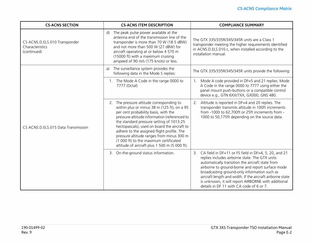
Transponder TSO Installation ManualPage E-2
CS-ACNS Compliance Matrix
/345/345R units are a Class 1 g the higher requirements identified .c, when installed according to the .
/345/345R units provide the following:
provided in DF=5 and 21 replies. Mode range 0000 to 7777 using either the ush-buttons or a compatible control N 6XX/7XX, GX000, GNS 480.
rted in DF=4 and 20 replies. The ansmits altitude in 100ft increments 62,700ft or 25ft increments from -5ft depending on the source data.
11 or FS field in DF=4, 5, 20, and 21 s airborne state. The GTX units ransition the aircraft state from und-borne and report surface mode round-only information such as
and width. If the aircraft airborne state will report AIRBORNE with additional 1 with CA code of 6 or 7.
MPLIANCE SUMMARY
190-01499-02 GTX 3X5Rev. 9
CS ACNS.D.ELS.010 Transponder Characteristics(continued)
d) The peak pulse power available at the antenna end of the transmission line of the transponder is more than 70 W (18.5 dBW) and not more than 500 W (27 dBW) for aircraft operating at or below 4 570 m (15000 ft) with a maximum cruising airspeed of 90 m/s (175 knots) or less.
The GTX 335/335Rtransponder meetinin ACNS.D.ELS.010installation manual
CS ACNS.D.ELS.015 Data Transmission
a) The surveillance system provides the following data in the Mode S replies:
The GTX 335/335R
1. The Mode A Code in the range 0000 to 7777 (Octal)
1. Mode A code A Code in the panel mount pdevice e.g., GT
2. The pressure altitude corresponding to within plus or minus 38 m (125 ft), on a 95 per cent probability basis, with the pressure-altitude information (referenced to the standard pressure setting of 1013.25 hectopascals), used on board the aircraft to adhere to the assigned flight profile. The pressure altitude ranges from minus 300 m (1 000 ft) to the maximum certificated altitude of aircraft plus 1 500 m (5 000 ft).
2. Altitude is repotransponder trfrom -1000 to1000 to 50,17
3. On-the-ground status information. 3. CA field in DF=replies includeautomatically tairborne to grobroadcasting gaircraft lengthis unknown, itdetails in DF 1
CS-ACNS SECTION CS-ACNS ITEM DESCRIPTION CO
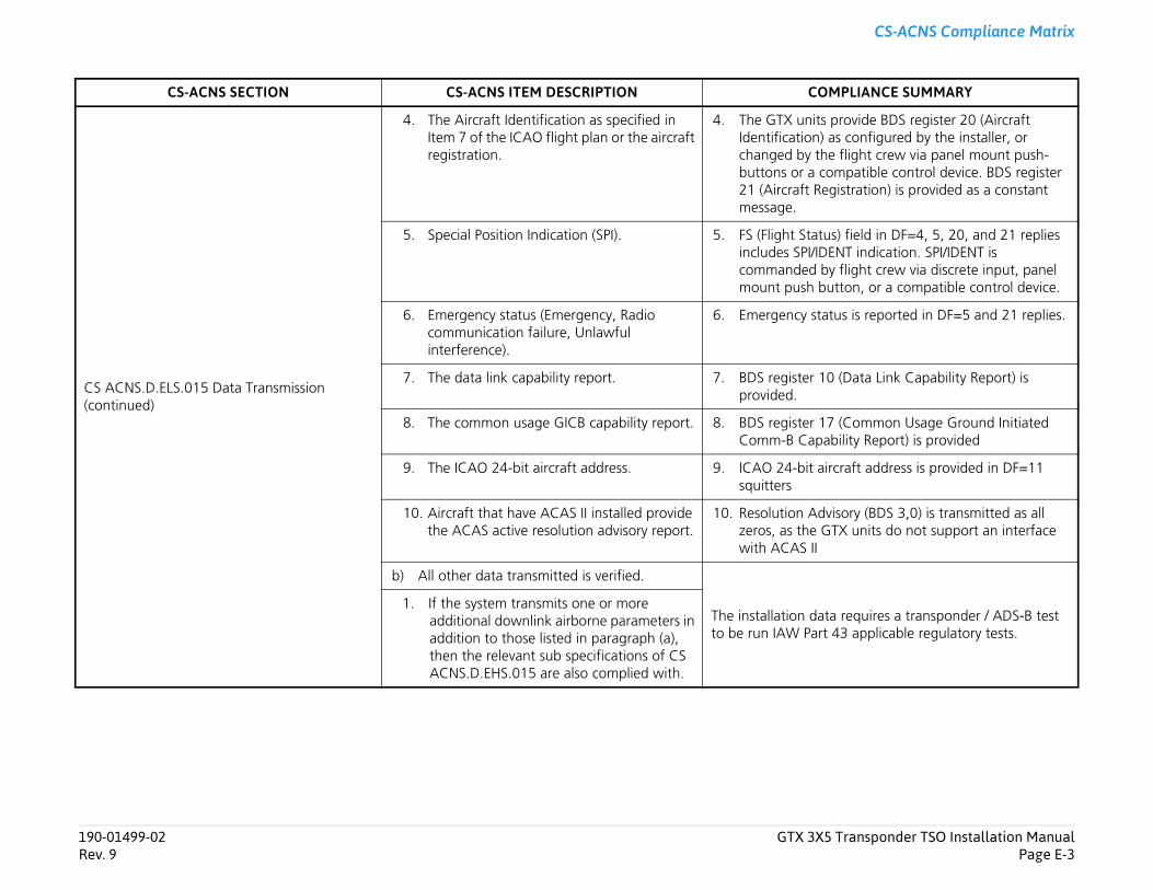
Transponder TSO Installation ManualPage E-3
CS-ACNS Compliance Matrix
provide BDS register 20 (Aircraft as configured by the installer, or e flight crew via panel mount push-mpatible control device. BDS register
gistration) is provided as a constant
s) field in DF=4, 5, 20, and 21 replies ENT indication. SPI/IDENT is y flight crew via discrete input, panel utton, or a compatible control device.
tus is reported in DF=5 and 21 replies.
0 (Data Link Capability Report) is
7 (Common Usage Ground Initiated bility Report) is provided
rcraft address is provided in DF=11
isory (BDS 3,0) is transmitted as all TX units do not support an interface
a requires a transponder / ADS-B test 43 applicable regulatory tests.
MPLIANCE SUMMARY
190-01499-02 GTX 3X5Rev. 9
CS ACNS.D.ELS.015 Data Transmission (continued)
4. The Aircraft Identification as specified in Item 7 of the ICAO flight plan or the aircraft registration.
4. The GTX unitsIdentification) changed by thbuttons or a co21 (Aircraft Remessage.
5. Special Position Indication (SPI). 5. FS (Flight Statuincludes SPI/IDcommanded bmount push b
6. Emergency status (Emergency, Radio communication failure, Unlawful interference).
6. Emergency sta
7. The data link capability report. 7. BDS register 1provided.
8. The common usage GICB capability report. 8. BDS register 1Comm-B Capa
9. The ICAO 24-bit aircraft address. 9. ICAO 24-bit aisquitters
10. Aircraft that have ACAS II installed provide the ACAS active resolution advisory report.
10. Resolution Advzeros, as the Gwith ACAS II
b) All other data transmitted is verified.
The installation datto be run IAW Part
1. If the system transmits one or more additional downlink airborne parameters in addition to those listed in paragraph (a), then the relevant sub specifications of CS ACNS.D.EHS.015 are also complied with.
CS-ACNS SECTION CS-ACNS ITEM DESCRIPTION CO
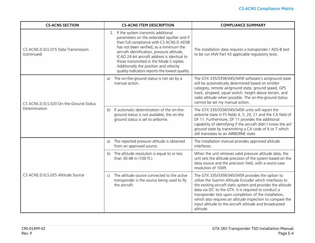
Transponder TSO Installation ManualPage E-4
CS-ACNS Compliance Matrix
a requires a transponder / ADS-B test 43 applicable regulatory tests.
/345/345R software's air/ground state ly determined based on emitter ir/ground state, ground speed, GPS at switch, height above terrain, and possible. The on-the-ground status anual action.
/345/345R units will report the fields 4, 5, 20, 21 and the CA field of , DF 11 provides the additional ying if the aircraft didn't know the air/nsmitting a CA code of 6 or 7 which AIRBORNE state.
nual provides approved altitude
ieves valid pressure altitude data, the e precision of the system based on the e precision field, with a worst-case .
/345/345R provides the option to Altitude Encoder which interfaces to static system and provides the altitude GTX. It is required to conduct a on completion of the installation, an altitude inspection to compare the e aircraft altitude and broadcasted
MPLIANCE SUMMARY
190-01499-02 GTX 3X5Rev. 9
CS ACNS.D.ELS.015 Data Transmission (continued)
2. If the system transmits additional parameters on the extended squitter and if their full compliance with CS ACNS.D.ADSB has not been verified, as a minimum the aircraft identification, pressure altitude, ICAO 24-bit aircraft address is identical to those transmitted in the Mode S replies. Additionally the position and velocity quality indicators reports the lowest quality.
The installation datto be run IAW Part
CS ACNS.D.ELS.020 On-the-Ground Status Determination
a) The on-the-ground status is not set by a manual action.
The GTX 335/335Rwill be automaticalcategory, remote atrack, airspeed, squradio altitude whencannot be set my m
b) If automatic determination of the on-the-ground status is not available, the on-the ground status is set to airborne.
The GTX 335/335Rairborne state in FSDF 11. Furthermorecapability of identifground state by trastill translates to an
CS ACNS.D.ELS.025 Altitude Source
a) The reported pressure altitude is obtained from an approved source.
The installation mainterfaces.
b) The altitude resolution is equal to or less than 30.48 m (100 ft.).
When the unit retrunit sets the altituddata source and thresolution of 100ft
c) The altitude source connected to the active transponder is the source being used to fly the aircraft.
The GTX 335/335Rutilize the Garmin the existing aircraftdata via I2C to thetransponder test upwhich also requiresinput altitude to thaltitude.
CS-ACNS SECTION CS-ACNS ITEM DESCRIPTION CO
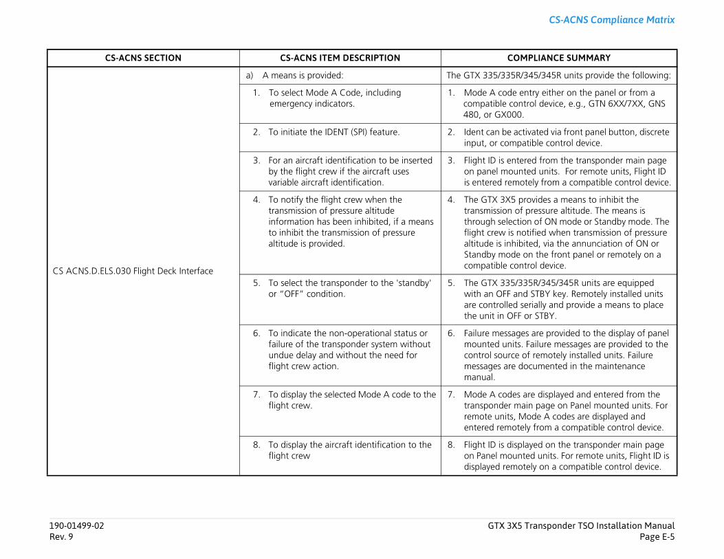
Transponder TSO Installation ManualPage E-5
CS-ACNS Compliance Matrix
/345/345R units provide the following:
entry either on the panel or from a trol device, e.g., GTN 6XX/7XX, GNS .
tivated via front panel button, discrete atible control device.
ered from the transponder main page ted units. For remote units, Flight ID
otely from a compatible control device.
rovides a means to inhibit the f pressure altitude. The means is ion of ON mode or Standby mode. The otified when transmission of pressure ited, via the annunciation of ON or
on the front panel or remotely on a ntrol device.
35R/345/345R units are equipped d STBY key. Remotely installed units serially and provide a means to place or STBY.
es are provided to the display of panel . Failure messages are provided to the of remotely installed units. Failure ocumented in the maintenance
are displayed and entered from the ain page on Panel mounted units. For
ode A codes are displayed and ely from a compatible control device.
layed on the transponder main page ted units. For remote units, Flight ID is tely on a compatible control device.
MPLIANCE SUMMARY
190-01499-02 GTX 3X5Rev. 9
CS ACNS.D.ELS.030 Flight Deck Interface
a) A means is provided: The GTX 335/335R
1. To select Mode A Code, including emergency indicators.
1. Mode A code compatible con480, or GX000
2. To initiate the IDENT (SPI) feature. 2. Ident can be acinput, or comp
3. For an aircraft identification to be inserted by the flight crew if the aircraft uses variable aircraft identification.
3. Flight ID is enton panel mounis entered rem
4. To notify the flight crew when the transmission of pressure altitude information has been inhibited, if a means to inhibit the transmission of pressure altitude is provided.
4. The GTX 3X5 ptransmission othrough selectflight crew is naltitude is inhibStandby modecompatible co
5. To select the transponder to the 'standby' or “OFF” condition.
5. The GTX 335/3with an OFF anare controlled the unit in OFF
6. To indicate the non-operational status or failure of the transponder system without undue delay and without the need for flight crew action.
6. Failure messagmounted unitscontrol sourcemessages are dmanual.
7. To display the selected Mode A code to the flight crew.
7. Mode A codestransponder mremote units, Mentered remot
8. To display the aircraft identification to the flight crew
8. Flight ID is dispon Panel moundisplayed remo
CS-ACNS SECTION CS-ACNS ITEM DESCRIPTION CO
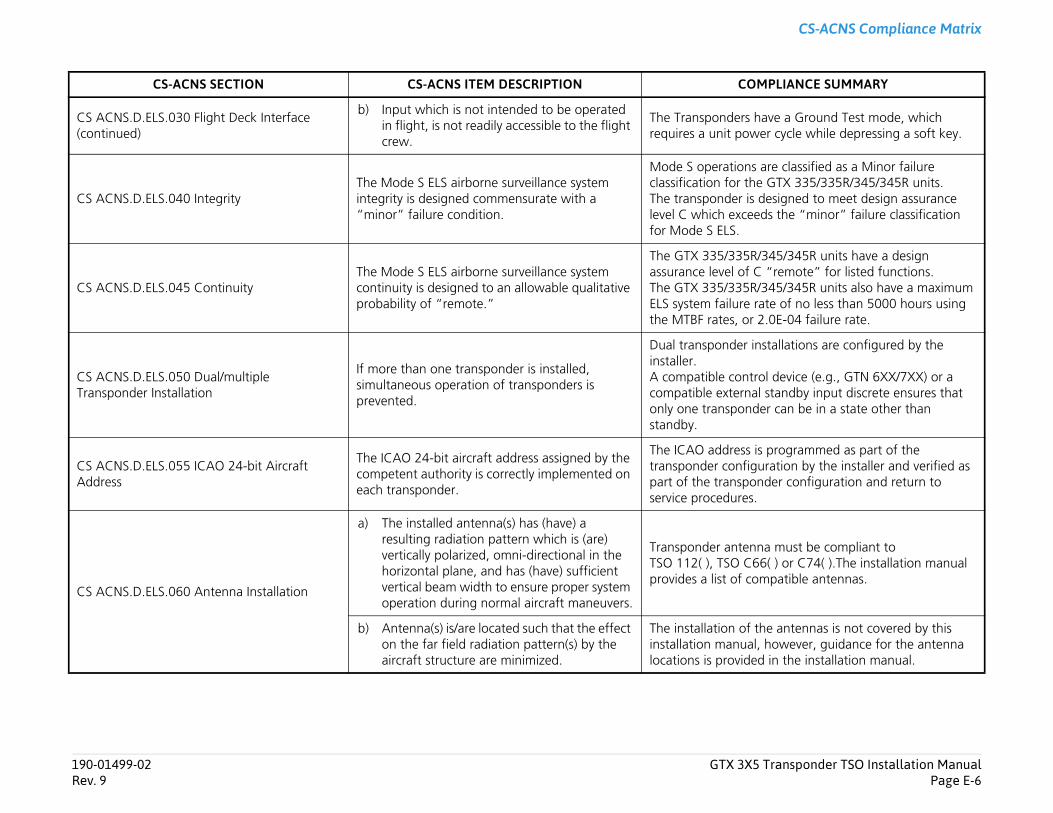
Transponder TSO Installation ManualPage E-6
CS-ACNS Compliance Matrix
ave a Ground Test mode, which er cycle while depressing a soft key.
are classified as a Minor failure e GTX 335/335R/345/345R units. designed to meet design assurance ds the “minor” failure classification
/345/345R units have a design “remote” for listed functions.
/345/345R units also have a maximum ate of no less than 5000 hours using 2.0E-04 failure rate.
nstallations are configured by the
ol device (e.g., GTN 6XX/7XX) or a l standby input discrete ensures that er can be in a state other than
is programmed as part of the uration by the installer and verified as nder configuration and return to
na must be compliant to 6( ) or C74( ).The installation manual mpatible antennas.
the antennas is not covered by this , however, guidance for the antenna d in the installation manual.
MPLIANCE SUMMARY
190-01499-02 GTX 3X5Rev. 9
CS ACNS.D.ELS.030 Flight Deck Interface(continued)
b) Input which is not intended to be operated in flight, is not readily accessible to the flight crew.
The Transponders hrequires a unit pow
CS ACNS.D.ELS.040 IntegrityThe Mode S ELS airborne surveillance system integrity is designed commensurate with a “minor” failure condition.
Mode S operationsclassification for thThe transponder islevel C which exceefor Mode S ELS.
CS ACNS.D.ELS.045 ContinuityThe Mode S ELS airborne surveillance system continuity is designed to an allowable qualitative probability of “remote.”
The GTX 335/335Rassurance level of CThe GTX 335/335RELS system failure rthe MTBF rates, or
CS ACNS.D.ELS.050 Dual/multiple Transponder Installation
If more than one transponder is installed, simultaneous operation of transponders is prevented.
Dual transponder iinstaller. A compatible contrcompatible externaonly one transpondstandby.
CS ACNS.D.ELS.055 ICAO 24-bit Aircraft Address
The ICAO 24-bit aircraft address assigned by the competent authority is correctly implemented on each transponder.
The ICAO address transponder configpart of the transposervice procedures.
CS ACNS.D.ELS.060 Antenna Installation
a) The installed antenna(s) has (have) a resulting radiation pattern which is (are) vertically polarized, omni-directional in the horizontal plane, and has (have) sufficient vertical beam width to ensure proper system operation during normal aircraft maneuvers.
Transponder antenTSO 112( ), TSO C6provides a list of co
b) Antenna(s) is/are located such that the effect on the far field radiation pattern(s) by the aircraft structure are minimized.
The installation of installation manuallocations is provide
CS-ACNS SECTION CS-ACNS ITEM DESCRIPTION CO
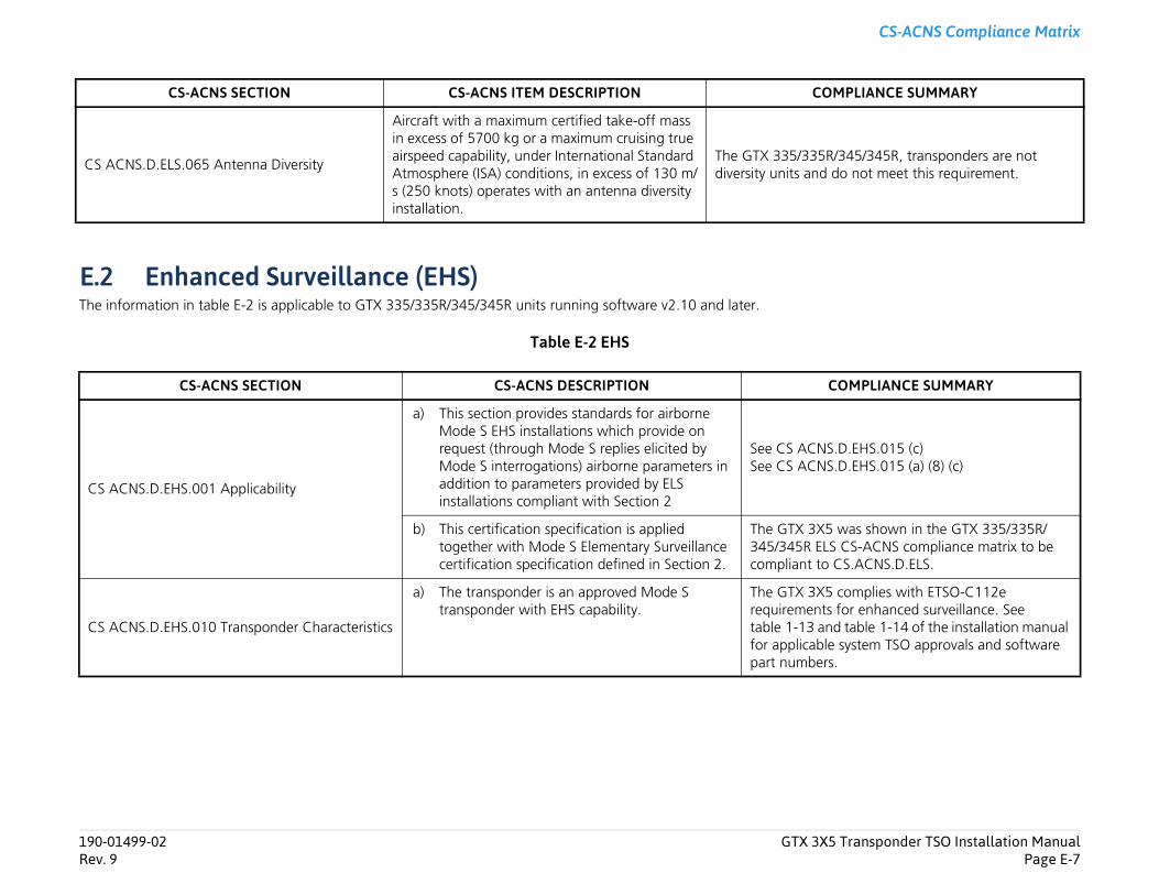
Transponder TSO Installation ManualPage E-7
CS-ACNS Compliance Matrix
/345/345R, transponders are not do not meet this requirement.
OMPLIANCE SUMMARY
.D.EHS.015 (c)
.D.EHS.015 (a) (8) (c)
was shown in the GTX 335/335R/ CS-ACNS compliance matrix to be CS.ACNS.D.ELS.
complies with ETSO-C112e for enhanced surveillance. See d table 1-14 of the installation manual system TSO approvals and software .
MPLIANCE SUMMARY
190-01499-02 GTX 3X5Rev. 9
E.2 Enhanced Surveillance (EHS)The information in table E-2 is applicable to GTX 335/335R/345/345R units running software v2.10 and later.
Table E-2 EHS
CS ACNS.D.ELS.065 Antenna Diversity
Aircraft with a maximum certified take-off mass in excess of 5700 kg or a maximum cruising true airspeed capability, under International Standard Atmosphere (ISA) conditions, in excess of 130 m/s (250 knots) operates with an antenna diversity installation.
The GTX 335/335Rdiversity units and
CS-ACNS SECTION CS-ACNS DESCRIPTION C
CS ACNS.D.EHS.001 Applicability
a) This section provides standards for airborne Mode S EHS installations which provide on request (through Mode S replies elicited by Mode S interrogations) airborne parameters in addition to parameters provided by ELS installations compliant with Section 2
See CS ACNSSee CS ACNS
b) This certification specification is applied together with Mode S Elementary Surveillance certification specification defined in Section 2.
The GTX 3X5345/345R ELScompliant to
CS ACNS.D.EHS.010 Transponder Characteristics
a) The transponder is an approved Mode S transponder with EHS capability.
The GTX 3X5requirementstable 1-13 anfor applicablepart numbers
CS-ACNS SECTION CS-ACNS ITEM DESCRIPTION CO
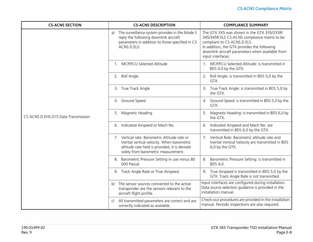
Transponder TSO Installation ManualPage E-8
CS-ACNS Compliance Matrix
was shown in the GTX 335/335R/ CS-ACNS compliance matrix to be CS.ACNS.D.ELS. e GTX provides the following
raft parameters when available from es:
Selected Altitude: is transmitted in by the GTX.
le: is transmitted in BDS 5,0 by the
k Angle: is transmitted in BDS 5,0 by
peed: is transmitted in BDS 5,0 by the
c Heading: is transmitted in BDS 6,0 by
Airspeed and Mach No: are ed in BDS 6,0 by the GTX.
ate: Barometric altitude rate and ertical Velocity are transmitted in BDS e GTX.
ric Pressure Setting: is transmitted in
peed is transmitted in BDS 5,0 by the ck Angle Rate is not transmitted.
s are configured during installation. lection guidance is provided in the nual.
cedures are provided in the installation dic inspections are also required.
OMPLIANCE SUMMARY
190-01499-02 GTX 3X5Rev. 9
CS ACNS.D.EHS.015 Data Transmission
a) The surveillance system provides in the Mode S reply the following downlink aircraft parameters in addition to those specified in CS ACNS.D.ELS:
The GTX 3X5345/345R ELScompliant to In addition, thdownlink aircinput interfac
1. MCP/FCU Selected Altitude 1. MCP/FCUBDS 4,0
2. Roll Angle 2. Roll AngGTX.
3. True Track Angle 3. True Tracthe GTX.
4. Ground Speed 4. Ground SGTX.
5. Magnetic Heading 5. Magnetithe GTX.
6. Indicated Airspeed or Mach No. 6. Indicatedtransmitt
7. Vertical rate: Barometric Altitude rate or Inertial vertical velocity. When barometric altitude rate field is provided, it is derived solely from barometric measurement.
7. Vertical RInertial V6,0 by th
8. Barometric Pressure Setting in use minus 80 000 Pascal.
8. BarometBDS 4,0.
9. Track Angle Rate or True Airspeed. 9. True AirsGTX. Tra
b) The sensor sources connected to the active transponder are the sensors relevant to the aircraft flight profile.
Input interfaceData source seinstallation ma
c) All transmitted parameters are correct and are correctly indicated as available.
Check-out promanual. Perio
CS-ACNS SECTION CS-ACNS DESCRIPTION C
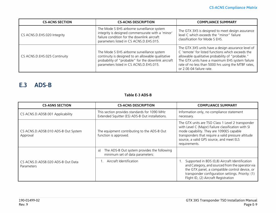
Transponder TSO Installation ManualPage E-9
CS-ACNS Compliance Matrix
is designed to meet design assurance exceeds the “minor” failure for Mode S EHS.
units have a design assurance level of r listed functions which exceeds the litative probability of “probable.”
s have a maximum EHS system failure s than 5000 hrs using the MTBF rates, ilure rate.
OMPLIANCE SUMMARY
nly, no compliance statement
s are TSO Class 1 Level 2 transponder (Major) Failure classification with SI lity. They are 1090ES capable that require a valid pressure altitude d GPS source, and meet ELS .
d in BDS (0,8) Aircraft Identification gory, and sourced from the operator via panel, a compatible control device, or der configuration settings. Priority: (1) (2) Aircraft Registration
OMPLIANCE SUMMARY
190-01499-02 GTX 3X5Rev. 9
E.3 ADS-BTable E-3 ADS-B
CS ACNS.D.EHS.020 Integrity
The Mode S EHS airborne surveillance system integrity is designed commensurate with a 'minor' failure condition for the downlink aircraft parameters listed in CS ACNS.D.EHS.015.
The GTX 3X5level C whichclassification
CS ACNS.D.EHS.025 ContinuityThe Mode S EHS airborne surveillance system continuity is designed to an allowable qualitative probability of “probable” for the downlink aircraft parameters listed in CS ACNS.D.EHS.015.
The GTX 3X5C 'remote' foallowable quaThe GTX unitrate of no lesor 2.0E-04 fa
CS-ASNS SECTION CS-ACNS DESCRIPTION C
CS ACNS.D.ADSB.001 ApplicabilityThis section provides standards for 1090 MHz Extended Squitter (ES) ADS-B Out installations.
Information onecessary.
CS ACNS.D.ADSB.010 ADS-B Out System Approval
The equipment contributing to the ADS-B Out function is approved.
The GTX unitwith Level C mode capabitransponderssource, a valirequirements
CS ACNS.D.ADSB.020 ADS-B Out Data Parameters
a) The ADS-B Out system provides the following minimum set of data parameters:
1. Aircraft Identification 1. Supporteand Catethe GTX transponFlight ID,
CS-ACNS SECTION CS-ACNS DESCRIPTION C

Transponder TSO Installation ManualPage E-10
CS-ACNS Compliance Matrix
code is supported in BDS (6,1) and from the transponder main page on unted units. For remote units, Mode A
e provided / entered remotely via a le control device.
7 squitter transmissions provide the dress. Aircraft address data is sourced nsponder internal configuration
pported in BDS (0,5) Airborne Position
pported in BDS (0,5) Airborne Position
pported in BDS (6,2) Target State and tus and (6,5) Aircraft Operational tus
pported in BDS (6,2) Target State and tus and (6,5) Aircraft Operational tus
pported in BDS (6,5) Aircraft erational Status
OMPLIANCE SUMMARY
190-01499-02 GTX 3X5Rev. 9
CS ACNS.D.ADSB.020 ADS-B Out Data Parameters(continued)
2. Mode A Code 2. Mode A entered Panel mocodes arcompatib
3. ICAO 24-bit aircraft address 3. All DF=1ICAO adfrom trasettings.
4. 4.
a. Airborne Horizontal Position - Latitude and Longitude
a. Su
b. Airborne Navigation Integrity Category: NIC
b. Su
c. Airborne/Surface Navigation Accuracy Category for Position: NACp
c. SuStaSta
d. Airborne/Surface Source Integrity Level: SIL
d. SuStaSta
e. Airborne/Surface System Design Assurance: SDA
e. SuOp
CS-ASNS SECTION CS-ACNS DESCRIPTION C
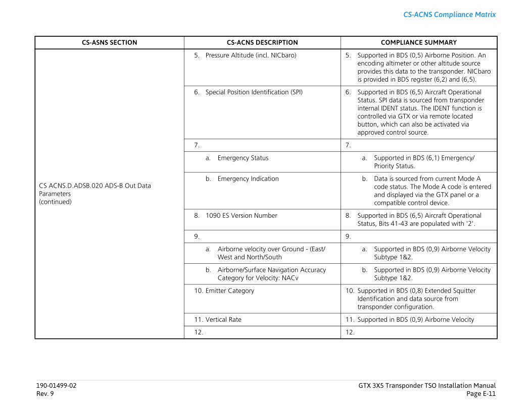
Transponder TSO Installation ManualPage E-11
CS-ACNS Compliance Matrix
d in BDS (0,5) Airborne Position. An altimeter or other altitude source
this data to the transponder. NICbaro ed in BDS register (6,2) and (6,5).
d in BDS (6,5) Aircraft Operational PI data is sourced from transponder IDENT status. The IDENT function is d via GTX or via remote located hich can also be activated via control source.
pported in BDS (6,1) Emergency/ority Status.
ta is sourced from current Mode A e status. The Mode A code is entered
d displayed via the GTX panel or a patible control device.
d in BDS (6,5) Aircraft Operational its 41-43 are populated with '2'.
pported in BDS (0,9) Airborne Velocity btype 1&2.
pported in BDS (0,9) Airborne Velocity btype 1&2.
d in BDS (0,8) Extended Squitter tion and data source from der configuration.
d in BDS (0,9) Airborne Velocity
OMPLIANCE SUMMARY
190-01499-02 GTX 3X5Rev. 9
CS ACNS.D.ADSB.020 ADS-B Out Data Parameters(continued)
5. Pressure Altitude (incl. NICbaro) 5. Supporteencodingprovidesis provid
6. Special Position Identification (SPI) 6. SupporteStatus. Sinternal controllebutton, wapproved
7. 7.
a. Emergency Status a. SuPri
b. Emergency Indication b. Dacodancom
8. 1090 ES Version Number 8. SupporteStatus, B
9. 9.
a. Airborne velocity over Ground - (East/West and North/South
a. SuSu
b. Airborne/Surface Navigation Accuracy Category for Velocity: NACv
b. SuSu
10. Emitter Category 10. SupporteIdentificatranspon
11. Vertical Rate 11. Supporte
12. 12.
CS-ASNS SECTION CS-ACNS DESCRIPTION C
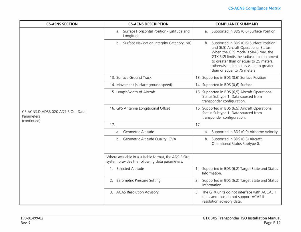
Transponder TSO Installation ManualPage E-12
CS-ACNS Compliance Matrix
pported in BDS (0,6) Surface Position
pported in BDS (0,6) Surface Position d (6,5) Aircraft Operational Status. en the GPS mode is SBAS Nav, the X 3X5 limits the radius of containment greater than or equal to 25 meters, erwise it limits this value to greater n or equal to 75 meters
d in BDS (0,6) Surface Position
d in BDS (0,6) Surface
d in BDS (6,5) Aircraft Operational btype 1. Data sourced from der configuration.
d in BDS (6,5) Aircraft Operational btype 1. Data sourced from der configuration.
pported in BDS (0,9) Airborne Velocity.
pported in BDS (6,5) Aircraft erational Status Subtype 0.
d in BDS (6,2) Target State and Status ion.
d in BDS (6,2) Target State and Status ion.
units do not interface with ACCAS II thus do not support ACAS II
n advisory data.
OMPLIANCE SUMMARY
190-01499-02 GTX 3X5Rev. 9
CS ACNS.D.ADSB.020 ADS-B Out Data Parameters(continued)
a. Surface Horizontal Position - Latitude and Longitude
a. Su
b. Surface Navigation Integrity Category: NIC b. SuanWhGTto oththa
13. Surface Ground Track 13. Supporte
14. Movement (surface ground speed) 14. Supporte
15. Length/width of Aircraft 15. SupporteStatus Sutranspon
16. GPS Antenna Longitudinal Offset 16. SupporteStatus Sutranspon
17. 17.
a. Geometric Altitude a. Su
b. Geometric Altitude Quality: GVA b. SuOp
Where available in a suitable format, the ADS-B Out system provides the following data parameters:
1. Selected Altitude 1. SupporteInformat
2. Barometric Pressure Setting 2. SupporteInformat
3. ACAS Resolution Advisory 3. The GTXunits andresolutio
CS-ASNS SECTION CS-ACNS DESCRIPTION C
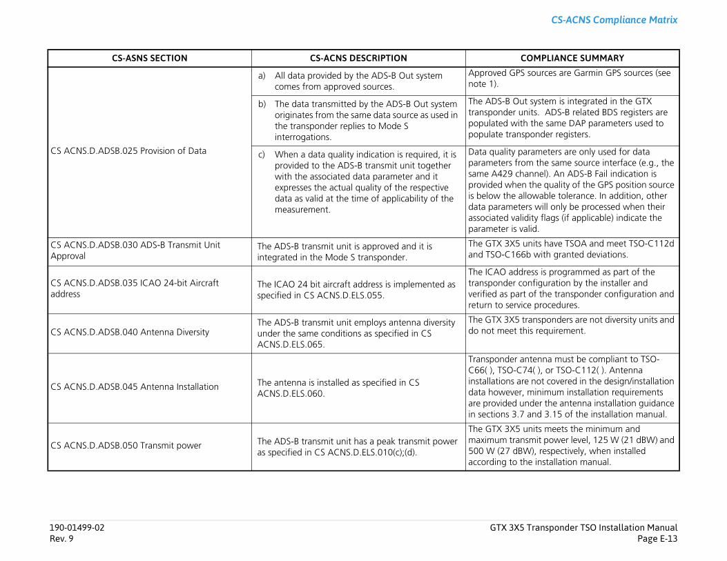
Transponder TSO Installation ManualPage E-13
CS-ACNS Compliance Matrix
sources are Garmin GPS sources (see
t system is integrated in the GTX nits. ADS-B related BDS registers are h the same DAP parameters used to sponder registers.
arameters are only used for data om the same source interface (e.g., the annel). An ADS-B Fail indication is
n the quality of the GPS position source llowable tolerance. In addition, other ers will only be processed when their idity flags (if applicable) indicate the alid.
units have TSOA and meet TSO-C112d 6b with granted deviations.
ress is programmed as part of the onfiguration by the installer and t of the transponder configuration and ice procedures.
transponders are not diversity units and his requirement.
ntenna must be compliant to TSO-74( ), or TSO-C112( ). Antenna re not covered in the design/installation , minimum installation requirements nder the antenna installation guidance and 3.15 of the installation manual.
units meets the minimum and smit power level, 125 W (21 dBW) and W), respectively, when installed he installation manual.
OMPLIANCE SUMMARY
190-01499-02 GTX 3X5Rev. 9
CS ACNS.D.ADSB.025 Provision of Data
a) All data provided by the ADS-B Out system comes from approved sources.
Approved GPSnote 1).
b) The data transmitted by the ADS-B Out system originates from the same data source as used in the transponder replies to Mode S interrogations.
The ADS-B Outransponder upopulated witpopulate tran
c) When a data quality indication is required, it is provided to the ADS-B transmit unit together with the associated data parameter and it expresses the actual quality of the respective data as valid at the time of applicability of the measurement.
Data quality pparameters frsame A429 chprovided wheis below the adata parametassociated valparameter is v
CS ACNS.D.ADSB.030 ADS-B Transmit Unit Approval
The ADS-B transmit unit is approved and it is integrated in the Mode S transponder.
The GTX 3X5 and TSO-C16
CS ACNS.D.ADSB.035 ICAO 24-bit Aircraft address
The ICAO 24 bit aircraft address is implemented as specified in CS ACNS.D.ELS.055.
The ICAO addtransponder cverified as parreturn to serv
CS ACNS.D.ADSB.040 Antenna DiversityThe ADS-B transmit unit employs antenna diversity under the same conditions as specified in CS ACNS.D.ELS.065.
The GTX 3X5 do not meet t
CS ACNS.D.ADSB.045 Antenna Installation The antenna is installed as specified in CS ACNS.D.ELS.060.
Transponder aC66( ), TSO-Cinstallations adata howeverare provided uin sections 3.7
CS ACNS.D.ADSB.050 Transmit power The ADS-B transmit unit has a peak transmit power as specified in CS ACNS.D.ELS.010(c);(d).
The GTX 3X5 maximum tran500 W (27 dBaccording to t
CS-ASNS SECTION CS-ACNS DESCRIPTION C

Transponder TSO Installation ManualPage E-14
CS-ACNS Compliance Matrix
der installations are configured by the
control device (e.g., GTN 6XX/7XX) or a ternal standby input discrete ensures transponder can be in a state other
units automatically transitions the from airborne to ground-borne and mode, broadcasting ground-only ch as aircraft length and width based m within the GTX ADS-B system.
software's air/ground state will be determined based on emitter category, und state, ground speed, GPS track, t switch, height above terrain, and when possible. The on-the-ground be set my manual action.
sition data will be derived from sources.
in GPS source documentation (see
ocity data is ground speed and N/S E/W ed in BDS register (0,6) when on DS register (0,9) when airborne. Both elocity are used from the same selected e.
E-1 and table E-2 of the installation e GTX 3X5 ELS and EHS CS-ACNS atrices for Mode S, ELS and EHS data.
R/345/345R units with software version er are not EHS capable units.
OMPLIANCE SUMMARY
190-01499-02 GTX 3X5Rev. 9
CS ACNS.D.ADSB.055 Simultaneous Operation of ADS-B Transmit Units
If more than one ADS-B transmit unit is installed, simultaneous operation of the transmit systems is prevented.
Dual transponinstaller.
A compatible compatible exthat only one than standby.
CS ACNS.D.ADSB.060 On-the-ground status determination
a) The on-the-ground status is determined and validated by the ADS-B Out system.
The GTX 3X5 aircraft modereport surfaceinformation suon an algorith
b) The on-the-ground status is not set by a manual action.
The GTX 3X5 automatically remote air/groairspeed, squaradio altitude status cannot
CS ACNS.D.ADSB.070 Horizontal Position and Velocity Data Sources
a) The horizontal position is derived from GNSS data.
Horizontal poapproved GPS
b) The GNSS receiver based horizontal position and velocity data source is approved and performs, as a minimum, horizontal position receiver autonomous integrity monitoring (RAIM) and fault detection and exclusion (FDE).
Refer to GarmNote 1).
c) Horizontal velocity data stems from the same source as horizontal position data.
Horizontal velvelocity providground and Bposition and vposition sourc
CS ACNS.D.ADSB.080 Data Sources as defined by Mode S Elementary and Enhanced Surveillance
a) The data source requirements as defined for in section 2 and 3 of this subpart, are applicable.
Refer to tablemanual for thcompliance m
GTX 335/3352.05 and earli
CS-ASNS SECTION CS-ACNS DESCRIPTION C
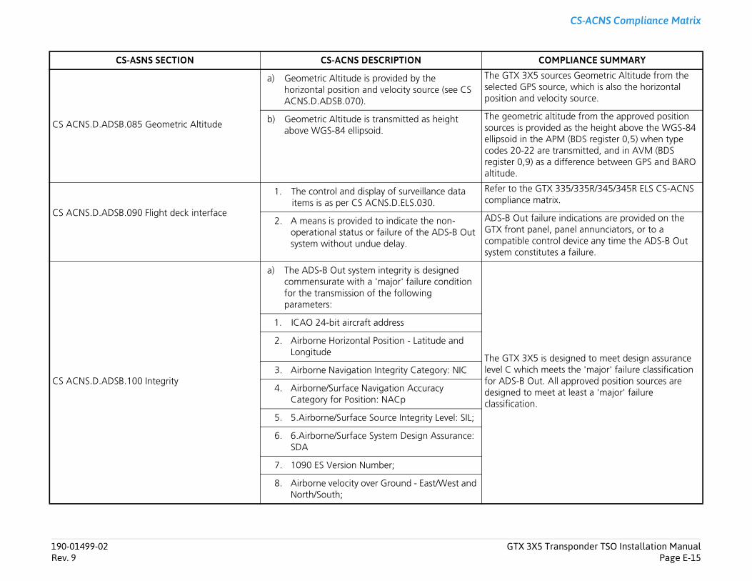
Transponder TSO Installation ManualPage E-15
CS-ACNS Compliance Matrix
sources Geometric Altitude from the source, which is also the horizontal elocity source.
altitude from the approved position vided as the height above the WGS-84 APM (BDS register 0,5) when type re transmitted, and in AVM (BDS s a difference between GPS and BARO
TX 335/335R/345/345R ELS CS-ACNS atrix.
ilure indications are provided on the el, panel annunciators, or to a ntrol device any time the ADS-B Out utes a failure.
is designed to meet design assurance meets the 'major' failure classification t. All approved position sources are eet at least a 'major' failure
OMPLIANCE SUMMARY
190-01499-02 GTX 3X5Rev. 9
CS ACNS.D.ADSB.085 Geometric Altitude
a) Geometric Altitude is provided by the horizontal position and velocity source (see CS ACNS.D.ADSB.070).
The GTX 3X5 selected GPS position and v
b) Geometric Altitude is transmitted as height above WGS-84 ellipsoid.
The geometricsources is proellipsoid in thecodes 20-22 aregister 0,9) aaltitude.
CS ACNS.D.ADSB.090 Flight deck interface
1. The control and display of surveillance data items is as per CS ACNS.D.ELS.030.
Refer to the Gcompliance m
2. A means is provided to indicate the non-operational status or failure of the ADS-B Out system without undue delay.
ADS-B Out faGTX front pancompatible cosystem constit
CS ACNS.D.ADSB.100 Integrity
a) The ADS-B Out system integrity is designed commensurate with a 'major' failure condition for the transmission of the following parameters:
The GTX 3X5 level C which for ADS-B Oudesigned to mclassification.
1. ICAO 24-bit aircraft address
2. Airborne Horizontal Position - Latitude and Longitude
3. Airborne Navigation Integrity Category: NIC
4. Airborne/Surface Navigation Accuracy Category for Position: NACp
5. 5.Airborne/Surface Source Integrity Level: SIL;
6. 6.Airborne/Surface System Design Assurance: SDA
7. 1090 ES Version Number;
8. Airborne velocity over Ground - East/West and North/South;
CS-ASNS SECTION CS-ACNS DESCRIPTION C
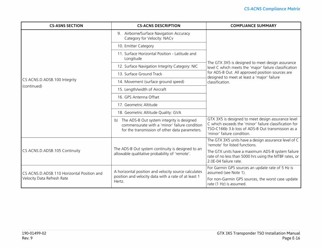
Transponder TSO Installation ManualPage E-16
CS-ACNS Compliance Matrix
is designed to meet design assurance meets the 'major' failure classification t. All approved position sources are eet at least a 'major' failure
signed to meet design assurance level ds the 'minor' failure classification for
.b loss of ADS-B Out transmission as a condition.
units have a design assurance level of C sted functions.
have a maximum ADS-B system failure than 5000 hrs using the MTBF rates, or e rate.
PS sources an update rate of 5 Hz is Note 1).
in GPS sources, the worst case update ssumed.
OMPLIANCE SUMMARY
190-01499-02 GTX 3X5Rev. 9
CS ACNS.D.ADSB.100 Integrity
(continued)
9. Airborne/Surface Navigation Accuracy Category for Velocity: NACv
The GTX 3X5 level C which for ADS-B Oudesigned to mclassification.
10. Emitter Category
11. Surface Horizontal Position - Latitude and Longitude
12. Surface Navigation Integrity Category: NIC
13. Surface Ground Track
14. Movement (surface ground speed)
15. Length/width of Aircraft
16. GPS Antenna Offset
17. Geometric Altitude
18. Geometric Altitude Quality: GVA
b) The ADS-B Out system integrity is designed commensurate with a 'minor' failure condition for the transmission of other data parameters.
GTX 3X5 is deC which exceeTSO-C166b 3'minor' failure
CS ACNS.D.ADSB.105 Continuity The ADS-B Out system continuity is designed to an allowable qualitative probability of 'remote'.
The GTX 3X5 'remote' for li
The GTX unitsrate of no less2.0E-04 failur
CS ACNS.D.ADSB.110 Horizontal Position and Velocity Data Refresh Rate
A horizontal position and velocity source calculates position and velocity data with a rate of at least 1 Hertz.
For Garmin Gassumed (see
For non-Garmrate (1 Hz) is a
CS-ASNS SECTION CS-ACNS DESCRIPTION C
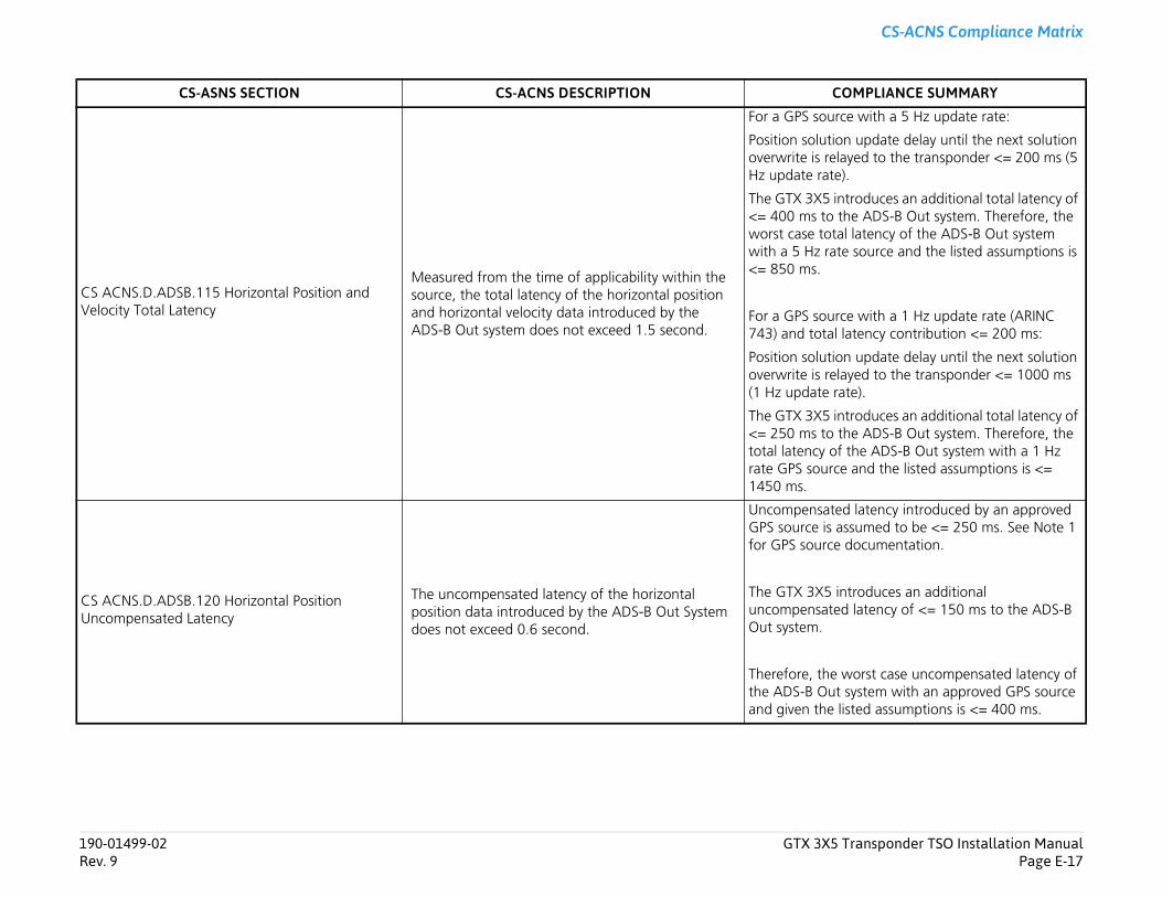
Transponder TSO Installation ManualPage E-17
CS-ACNS Compliance Matrix
rce with a 5 Hz update rate:
on update delay until the next solution layed to the transponder <= 200 ms (5 e).
introduces an additional total latency of the ADS-B Out system. Therefore, the al latency of the ADS-B Out system te source and the listed assumptions is
rce with a 1 Hz update rate (ARINC l latency contribution <= 200 ms:
on update delay until the next solution layed to the transponder <= 1000 ms rate).
introduces an additional total latency of the ADS-B Out system. Therefore, the f the ADS-B Out system with a 1 Hz ce and the listed assumptions is <=
ed latency introduced by an approved assumed to be <= 250 ms. See Note 1 e documentation.
introduces an additional ed latency of <= 150 ms to the ADS-B
worst case uncompensated latency of t system with an approved GPS source listed assumptions is <= 400 ms.
OMPLIANCE SUMMARY
190-01499-02 GTX 3X5Rev. 9
CS ACNS.D.ADSB.115 Horizontal Position and Velocity Total Latency
Measured from the time of applicability within the source, the total latency of the horizontal position and horizontal velocity data introduced by the ADS-B Out system does not exceed 1.5 second.
For a GPS sou
Position solutioverwrite is reHz update rat
The GTX 3X5 <= 400 ms toworst case totwith a 5 Hz ra<= 850 ms.
For a GPS sou743) and tota
Position solutioverwrite is re(1 Hz update
The GTX 3X5 <= 250 ms tototal latency orate GPS sour1450 ms.
CS ACNS.D.ADSB.120 Horizontal Position Uncompensated Latency
The uncompensated latency of the horizontal position data introduced by the ADS-B Out System does not exceed 0.6 second.
UncompensatGPS source is for GPS sourc
The GTX 3X5 uncompensatOut system.
Therefore, thethe ADS-B Ouand given the
CS-ASNS SECTION CS-ACNS DESCRIPTION C