Embed Size (px)
Citation preview
Guardian Series Lift TablesService Manual
LIFT PRODUCTS INCPO BOX 349 ELM GROVE WI 53122262-521-5720 FAX 262-521-5725Toll Free 877-543-8776
Model: LPBL-20-2-LSS/N ________________________________Customer____________________________
INSTRUCTIONS HANDBOOK FOR THE INSTALLATION
USE AND MAINTENANCE OF LIFT TABLES
INDEX
1
1. GENERAL INFORMATION
1.1 PURPOSE AND CONTENTS OF THE HANDBOOK1.2 MANUAL AUDIENCE1.3 MANUFACTURER LIABILITY1.4 WARRANTY1.5 MANUFACTURER’S IDENTIFICATION1.6 MACHINE IDENTIFICATION1.7 REQUIREMENTS AND STANDARDS
2. USE, AREAS OF USE, SOUND EMISSIONS
2.1 RECYCLING INSTRUCTIONS
3. TECHNICAL SPECIFICATION FOR STANDARD MODELS
3.1 LOAD DISTRIBUTION
4. SAFETY INSTRUCTIONS
5. CHECKS UPON DELIVERY
6. PLATES AND LABELS ON THE TABLE
6.1 PLATE AND LABEL POSITIONS
7. TABLE OPERATION
8. INSTALLATION
8.1 CHECKS AT INITIAL START-UP8.2 CONNECTION TO THE POWER SUPPLY8.3 RATED CURRENT8.4 APPLICATION OF SAFETY STRUTS8.5 HOLE DESIGN8.6 INSTALLING THE TABLE IN THE HOLE
PAGE 3
PAGE 3PAGE 3PAGE 3PAGE 4PAGE 4PAGE 4PAGE 4
PAGE 5
PAGE 5
PAGE 6
PAGE 6
PAGE 7
PAGE 7
PAGE 8
PAGE 8
PAGE 9
PAGE 10
PAGE 10PAGE 11PAGE 11PAGE 11PAGE 12PAGE 13
2
9. COMPONENTS
9.1 HYDRAULIC SYSTEM9.2 ELECTRICAL SYSTEM9.3 HYDRAULIC VALVES9.4 MECHANICAL COMPONENTS9.5 OPERATIONS AFTER USE
10. MAINTENANCE INSTRUCTIONS
10.1 SAFE MAINTENANCE10.2 MAINTENANCE OPERATIONS10.3 HYDRAULIC SYSTEM10.4 ELECTRICAL SYSTEM10.5 MECHANICAL COMPONENTS10.6 LUBRICATION POINTS
(if pins with grease nipples are installed)
11. TROUBLESHOOTING
11.1 PROBLEMS, CAUSES AND SOLUTIONS
12. RISKS CONNECTED WITH TABLE USE
12.1 RISK TABLE
13. SPARE PARTS
13.1 METHOD FOR REQUESTING SPARE PARTS13.2 ORDERING SPARE PARTS
14. DISPOSAL AND SCRAPING
PAGE 13
PAGE 13PAGE 14PAGE 14PAGE 15PAGE 15
PAGE 16
PAGE 16PAGE 16PAGE 16PAGE 16PAGE 16PAGE 17
PAGE 18
PAGE 18
PAGE 19
PAGE 19
PAGE 20
PAGE 20PAGE 20
PAGE 20

3
1. GENERAL INFORMATION
1.1 PURPOSE AND CONTENT OF THE MANUAL
This manual describes the lift table, the functional technical specifications as well as instructions for its use, installation and maintenance. The following documentation is also provided together with this manual:CE declaration of conformity or manufacturer declaration pursuant to Annex VII B (Machine Directive 2006/42/EC). All documents are contained in transparent protective envelopes and are attached to the table.
1.2 MANUAL AUDIENCE
This handbook is intended for:• the manager of the plant, workshop or yard;• installation personnel;• maintenance personnel.
The manual must be kept by a person who is responsible for it, in a suitable location so that it can always be consulted and kept in good conditions. If lost or damaged, replacement documentation can be requested, indicating the serial number of the table, either directly from Lift Products Inc or your local dealer. Anyone who uses the table must be fully informed of the information in the manual. It is prohibited to make any changes to the manual without prior written authorisation from the manufacturer. The instruction manual and the manufacturer’s declaration of conformity must be kept with the machine when it is sold to others.
1.3 MANUFACTURER’S LIABILITY
The instructions in this manual do not replace but supplement the obligations for complying with current safety and accident prevention regulations. With reference to what is specified in this manual, Lift Products Inc declines all liability in the case of:
• installation of the table that does not comply with current national safety laws required according to table use
• improper use of the table according to national safety and accident prevention laws; • failure to observe or incorrect observance of the instructions provided in the manual,• mains voltage and power supply defects;• unauthorized mechanical modifications;• use by untrained personnel.
In order for the manufacturer warranty to be valid, as described in paragraph 1.4 of this man-ual, the customer must scrupulously observe the requirements set forth in the manual and in particular:
• always work within the limits of use of equipment;• perform constant and careful maintenance;• assign only operators with demonstrated ability and who have been suitably trained to
use the table; only use original spare parts indicated by the manufacturer.

4
1.4 WARRANTY
Lift Products Inc. Guarantees all tables for 12 months for a use of 8 hours a day for each working day, within the cycle/hour limits specified in the offer, starting from the shipping date. If used more that 8 hours per day the warranty period shall be reduced proportionately. The warranty is limited to replacing the parts that the company deems defective due to material or machining defects ex Lift Products Inc. works and does not include labor or travel costs for replacing said parts. It is further understood that recognition of the warranty is void if the anomaly results from an inappropriate use of the products, if commissioning was not carried out according to Lift Products specifications or if non-original parts have been used. Lift Products Inc products are not guaranteed for uses that exceed the ratings stated on the plates and in the documentation. All the equipment manufactured by Lift Products Inc. is insured for any damage caused to third parties by defective parts or their malfunction; damage arising from improper use or misuse of the tables is not covered.
1.5 MANUFACTURER’S IDENTIFICATION
This documentation entitled “INSTRUCTIONS MANUAL FOR THE INSTALLATION, USE AND MAINTENANCE OF LIFT TABLES” is only valid for tables manufactured by:Lift Products Inc •PO BOX 349•Elm Grove, WI 53122
1.6 MACHINE IDENTIFICATION
Every table has an identification plate that includes:• Manufacturer logo;• name, company name and address of the manufacturer;• table model;• max capacity in Kg,• year of manufacture;• serial number;• CE mark;• working pressure;• weight in Kg;• IP protection.
1.7 REQUIREMENTS, STANDARDS
Lift Products Inc. lift tables were designed and built in order to guarantee maximum safety, reliability and duration. They comply with the basic requirements specified by the standard EN 1570 for lift tables. This European standard determines the safety requirements for lift tables used for lifting and/or lowering goods and/or people assigned to moving the material transported by the lift tables with maximum vertical travel of 3m. They may be manually operated or equipped with an electric motor. Accessories can be installed to improve safety.

5
2. USE AND AREAS OF USE
The product is designed for use in dry, well lit rooms with moderate temperatures unless oth-erwise agreed upon with Lift Products. In addition to the safety devices of the table, additional safety measures may be necessary both for the table as well as for the surrounding work area. It is recommended to carry out a risk analysis in accordance to what is set forth by the machine di-rective. See also the section “Risks connected with operation”. These instructions must be made available to authorised personnel and must be kept with the product during its entire operative life. Lift Products lift tables can be used in many situations. They are generally used for lifting/lowering loads. They are designed to be used on a flat and stable base or on the floor. They may be installed on the ground or inserted in a hole. The floor/ground must resist to the com-bined weight of the table and the load. The necessary information related to use and the load is included in this manual and refers to EN 1570. During normal operation, sound emission must not exceed 70dB(A), measured at a distance of 1 metre and at a height of 1.6 from the greatest sound source.
2.1 RECYCLING INSTRUCTIONS
Reusable or recyclable material were used to manufacture the lift tables. Worn tables must be disposed of by specialized companies, who will dismantle them and reuse the recyclable materi-als.
6
3. TECHNICAL SPECIFICATION FOR STANDARD MODELS
3.1 LOAD DISTRIBUTION
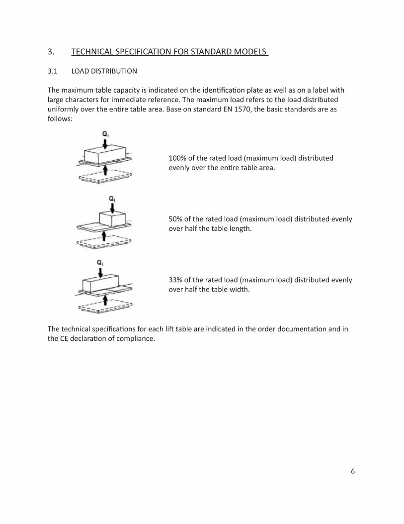
The maximum table capacity is indicated on the identification plate as well as on a label with large characters for immediate reference. The maximum load refers to the load distributed uniformly over the entire table area. Base on standard EN 1570, the basic standards are as follows:
100% of the rated load (maximum load) distributed evenly over the entire table area.
50% of the rated load (maximum load) distributed evenly over half the table length.
33% of the rated load (maximum load) distributed evenly over half the table width.
The technical specifications for each lift table are indicated in the order documentation and in the CE declaration of compliance.
7
4. SAFETY INSTRUCTIONS• Lift Products tables must only be used by authorized and suitably trained personnel. The
operator is responsible for preventing accidents. • Use the Lift Products tables only for the foreseen purposes and in completely safe
conditions. To prevent creating instability, do not overload the tables and try to position the load at the center.
• Check that the product is good condition before starting each work shift. • Maintenance and repair work must be carried out by qualified personnel. • If a fault is discovered, do not use the product until the malfunction has been resolved.• The operator must have a detailed view of the dangerous table parts and its load at each
movement during vertical movement. • Never insert hands, arms, feet or other body parts or any type of object inside the lifted
table. • Lower the table only after checking that no obstacles or people are located in the space
under the table. • Never move the table with the load lifted, as it could overturn.• Make sure hat the moving parts do not come into contact with adjacent objects,• Check that the table is used on a horizontal and level foundation.• Lifts with tipping must always be anchored to the ground.• Do not use Lift Products tables as a work bench for welding, unless they have been
specifically designed for this use.• Do not use the product in a potentially explosive environment.• Lift Products tables are not electrically insulated, therefore they do not provide any
protection for an operator who come into contact with live wires or objects.• Maintain a safe distance from live wires and objects.• Do not alter or modify components of fundamental importance for purposes of safety
and stability.• Loads must not be present during inspections and maintenance and repair work. Lock
the lifting mechanism with safety struts.
5. CHECKS UPON DELIVERY• The table must be delivery completely closed and equipped with lifting eyebolts for
transport and installation.• The position of the eyebolts must be visible and marked by suitable labels.• Make sure that the capacity (indicated on the data plate) of the forklift, crane or
overhead crane is suitable for the weight of the table.• Keep the eyebolts if it is necessary to move the table.• Make sure that all parts of the table have been inspected by the manufacturer.• The internal inspection report confirms the positive result of the tests that were carried
out.• Check that the standard electrical system includes a three-phase 380/400 V, 50 Hz
connection. • Make sure that the control system (safety perimeter, solenoid valve, limit switch etc.)
functions at a voltage of 24V DC.
8
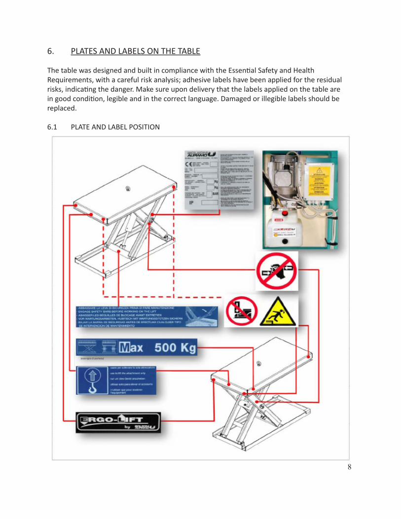
6. PLATES AND LABELS ON THE TABLE
The table was designed and built in compliance with the Essential Safety and Health Requirements, with a careful risk analysis; adhesive labels have been applied for the residual risks, indicating the danger. Make sure upon delivery that the labels applied on the table are in good condition, legible and in the correct language. Damaged or illegible labels should be replaced.
6.1 PLATE AND LABEL POSITION
9
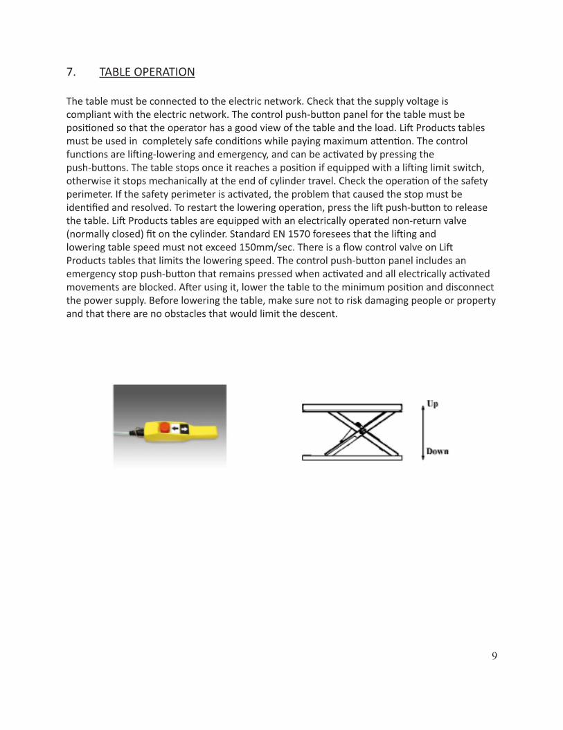
7. TABLE OPERATION
The table must be connected to the electric network. Check that the supply voltage is compliant with the electric network. The control push-button panel for the table must be positioned so that the operator has a good view of the table and the load. Lift Products tables must be used in completely safe conditions while paying maximum attention. The control functions are lifting-lowering and emergency, and can be activated by pressing the push-buttons. The table stops once it reaches a position if equipped with a lifting limit switch, otherwise it stops mechanically at the end of cylinder travel. Check the operation of the safety perimeter. If the safety perimeter is activated, the problem that caused the stop must be identified and resolved. To restart the lowering operation, press the lift push-button to release the table. Lift Products tables are equipped with an electrically operated non-return valve (normally closed) fit on the cylinder. Standard EN 1570 foresees that the lifting and lowering table speed must not exceed 150mm/sec. There is a flow control valve on Lift Products tables that limits the lowering speed. The control push-button panel includes an emergency stop push-button that remains pressed when activated and all electrically activated movements are blocked. After using it, lower the table to the minimum position and disconnect the power supply. Before lowering the table, make sure not to risk damaging people or property and that there are no obstacles that would limit the descent.

10
8. INSTALLATION
NB: Before installing the table, the eyebolts must be removed.
• The table must be installed by specialized personnel and must comply with current safety and accident prevention standards related to specific use of the table.
• Before installing the table, check the condition and completeness of the equipment. • During the installation procedure, the table must be completely unloaded. • It is necessary to fit a cut-off device on the power supply line, which must be accessible
for the operator during operation. • The table control unit must have an emergency stop device. • Check that the floor where the table is installed is perfectly flat.
8.1 CHECKS AT INITIAL START-UP
• Make sure that nothing was damaged during transport.• Do not carry out lifting operations on the safety perimeter.• Check that the safety perimeter is working properly and that its lifting causes the safety
microswitch to trip.

11
8.2 CONNECTION TO THE POWER SUPPLY
For the connection to the electric network, insert the power supply cable plug, which consists of four wires: three phases and ground. The EEC pin and network insulator are not included in the supply. If the motor starts but the table does not lift, invert the two phases. It is important that the motor does not operate for too long in the incorrect direction to prevent damaging the pump.
8.3 RATED CURRENT
Check the type of power supply, voltage and rated power of the motorKW= Rated motor powerIn= Rated currentA= Network fuseIf the power supply is single phase, the motor may have greater power.
8.4 APPLICATION OF SAFETY STRUTS
Safety struts must be applied during any operation carried out under or near the table. This also applies to installation, maintenance and inspections as well as for all repairs.
The safety struts must be installed on both sides
12
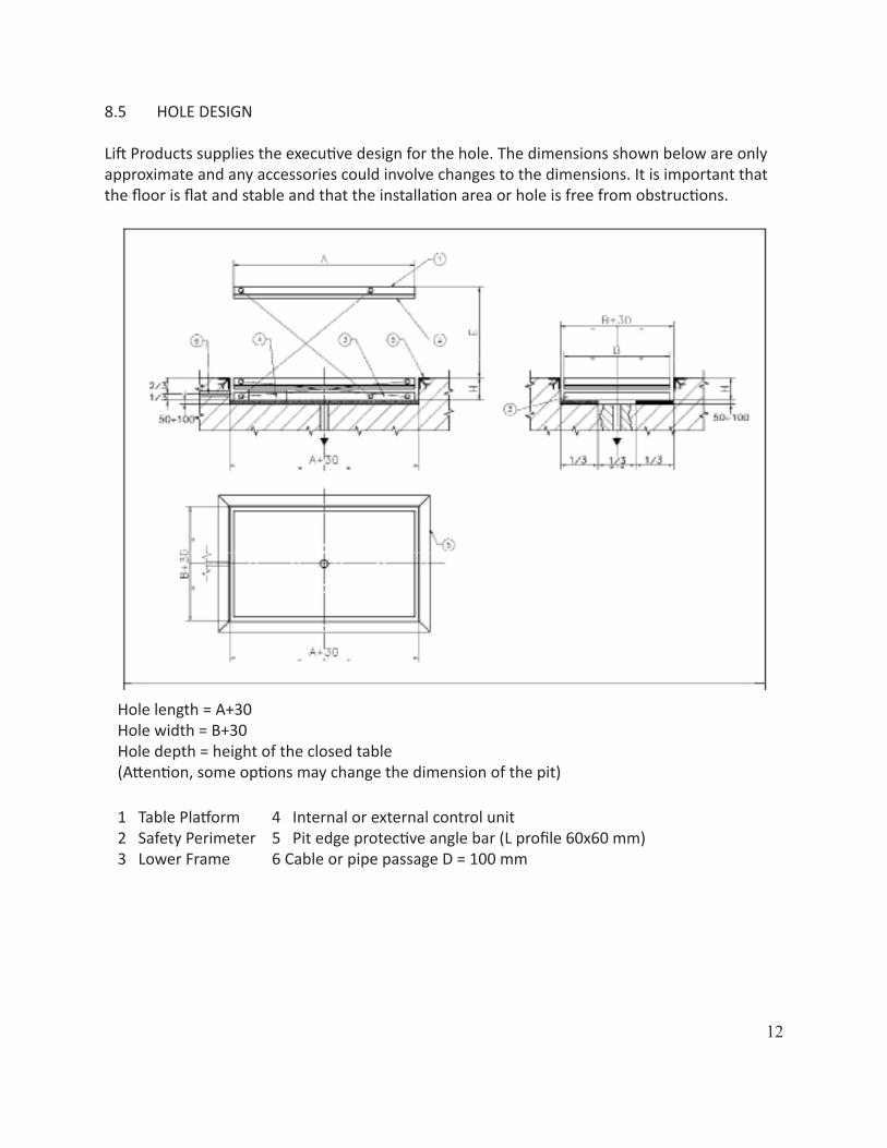
8.5 HOLE DESIGN
Lift Products supplies the executive design for the hole. The dimensions shown below are only approximate and any accessories could involve changes to the dimensions. It is important that the floor is flat and stable and that the installation area or hole is free from obstructions.
Hole length = A+30Hole width = B+30Hole depth = height of the closed table(Attention, some options may change the dimension of the pit)
1 Table Platform2 Safety Perimeter3 Lower Frame
4 Internal or external control unit5 Pit edge protective angle bar (L profile 60x60 mm)6 Cable or pipe passage D = 100 mm
13
8.6 INSTALLING THE TABLE IN THE HOLE (INTERNAL OR EXTERNAL CONTROL UNIT)
• Check that the diagonals of the hole are the same and that their dimensions are 30 mm greater than those of the table.
• It is important that the lower surface of the hole is perfectly parallel to the upper surface of the floor to ensure proper table operation. For small differences in level, adjust the adjustable mechanical struts, or use shims.
• Check for the presence of the supply pipe and cable duct and any water collection pit, for external installation.
• The operator is obliged to first check before inserting the table in the hole that no people and/or animals are located near the hole.
• Temporarily connect the control unit to the network and position the cable so it does not hinder inserting the table in the hole.
• Remove the eyebolts, lift and lower the safety bars.• Make the network connection, passing the cables and pipes in the duct.• Operate the table and test the functions.• Never exceed the maximum descent speed permitted for a full load. • Check the operation of the safety perimeter on all sides.• The push-button panel or the control unit (if external) must be positioned so that
the operator always has a detailed view of the table and the load when the table is operating.
9. COMPONENTS
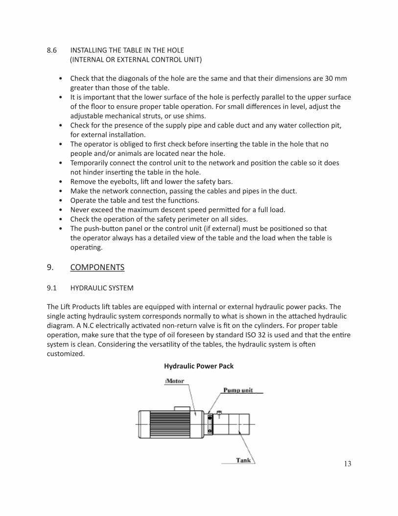
9.1 HYDRAULIC SYSTEM
The Lift Products lift tables are equipped with internal or external hydraulic power packs. The single acting hydraulic system corresponds normally to what is shown in the attached hydraulic diagram. A N.C electrically activated non-return valve is fit on the cylinders. For proper table operation, make sure that the type of oil foreseen by standard ISO 32 is used and that the entire system is clean. Considering the versatility of the tables, the hydraulic system is often customized.
Hydraulic Power Pack

14
9.2 ELECTRICAL SYSTEM
The lift tables have three-phase or single-phase connection with voltage to be defines. The network disconnecting switch is not supplied by Lift Products, and it must be fitted by the electrician upon installation. The power supply cable must be connected to the terminals of the disconnecting switch. The wiring diagram is included in this manual. Considering the versatility of the tables, the electrical system is often customized.
9.3 HYDRAULIC VALVES
Electrically activated non-return valve fit on the cylinders.
Safety valve fit directly on the cylinder bulkhead.
15
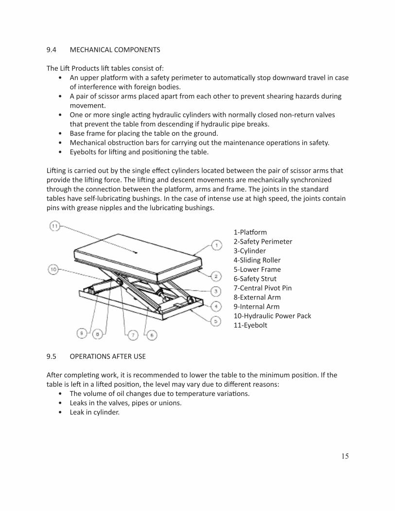
9.4 MECHANICAL COMPONENTS
The Lift Products lift tables consist of:• An upper platform with a safety perimeter to automatically stop downward travel in case
of interference with foreign bodies.• A pair of scissor arms placed apart from each other to prevent shearing hazards during
movement.• One or more single acting hydraulic cylinders with normally closed non-return valves
that prevent the table from descending if hydraulic pipe breaks.• Base frame for placing the table on the ground.• Mechanical obstruction bars for carrying out the maintenance operations in safety.• Eyebolts for lifting and positioning the table.
Lifting is carried out by the single effect cylinders located between the pair of scissor arms that provide the lifting force. The lifting and descent movements are mechanically synchronized through the connection between the platform, arms and frame. The joints in the standard tables have self-lubricating bushings. In the case of intense use at high speed, the joints contain pins with grease nipples and the lubricating bushings.
1-Platform2-Safety Perimeter3-Cylinder4-Sliding Roller5-Lower Frame6-Safety Strut7-Central Pivot Pin8-External Arm9-Internal Arm10-Hydraulic Power Pack11-Eyebolt
9.5 OPERATIONS AFTER USE
After completing work, it is recommended to lower the table to the minimum position. If the table is left in a lifted position, the level may vary due to different reasons:
• The volume of oil changes due to temperature variations.• Leaks in the valves, pipes or unions.• Leak in cylinder.
16
10. MAINTENANCE INSTRUCTIONS
10.1 SAFE MAINTENANCE
• Before carrying out any maintenance, make sure that the safety bars located at the base of the sliding arms are lowered.
• Before carrying out any maintenance work on the table, make sure that the load has been removed from the upper platform.
• When working on the mechanical and electrical parts, the main disconnecting switch must be deactivated.
• If a large or significant repair is carried out, the table must be reinspected in compliance with standard EN 1570, Annex C.
10.3 HYDRAULIC SYSTEM
• Check the level of oil in the tank, top up the oil if necessary with SHELL TELLUS OIL 46 or equivalent (data plate near the cap). If the oil is dirty, change it.
• Check for any leaks in the oil tank.• Inspect the hydraulic pipes and unions for any leaks or damage.• Check the cylinders; a possible oil leak makes it necessary to replace the gaskets and
carefully check the stem.• Check the seal on the valve and cylinders that must guarantee a maximum vertical
lowering of the table of 5 mm in 10 minutes with the platform completely lifted and with a maximum load (EN 1570).
10.4 ELECTRICAL SYSTEM
• Inspect and test the electrical functions.• Check that the cables and wires are intact. Fix them if necessary.• Check the operation of the safety perimeter microswitches and replace them if
necessary.
10.5 MECHANICAL COMPONENTS
• Check that all sliding wheels and pivot pins are correctly fitted.• Keep the roller tracks clean, do not grease them.• Check the wear of the bushings in the pivots and in the sliding rollers, checking
clearance.• Check for cracks or breaks in the welding.• Check that the safety perimeters are intact and not damaged.• Check that the table is stable.• Check that all labels are attached and clearly legible.
17
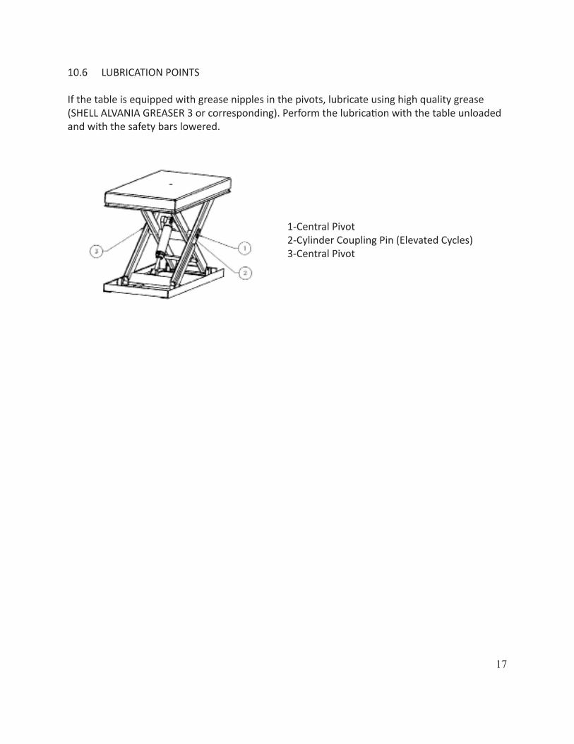
10.6 LUBRICATION POINTS
If the table is equipped with grease nipples in the pivots, lubricate using high quality grease (SHELL ALVANIA GREASER 3 or corresponding). Perform the lubrication with the table unloaded and with the safety bars lowered.
1-Central Pivot2-Cylinder Coupling Pin (Elevated Cycles)3-Central Pivot

18
11. TROUBLESHOOTING
The troubleshooting procedure must be carried out by expert personnel. In most cases, authorized personnel is an expert installer, specifically trained in mechanical parts. Lift Products technical personnel must intervene if any difficulties are encountered when troubleshooting or if the defect is different that those listed below. While carrying out the inspections or working underneath, position the safety bars.
11.1 PROBLEMS, CAUSES AND SOLUTIONSFAULT CAUSE REMEDY
The table does not lift; the mo-tor rotates normally.
Eyebolts still fitted. Remove them.
Retaining solenoid valve blocked in the open position.
Check the operation of the cursor and the solenoid; replace damaged parts.
Table overload Remove the load.The motor is rotating in the opposite direction. Invert two phases.
The table does not lift; the mo-tor does not rotate.
The ascent limit switch if fitted, is damaged.
Replace.Wait for the motor to cool, check the motor power supply and absorption.
The table does not descent.
The descent limit switch, if fitted, or a perimeter micro are damaged.
Replace.
The retaining solenoid valve is blocked or the solenoid is damaged.
Remove the retaining solenoid valve and clean it carefully. If necessary, replace the damaged parts.
The safety perimeter was triggered.
Restore operation by pressing the “UP” push-button on the push panel.
The table goes down also in the stop position. N.B Standard EN1570 forsees maximum verti-cal lowering of 5 mm in 10 min with the platform completely lifted and with the maximum load
The retaining solenoid valve lets oil seep through.
Remove the retaining solenoid valve and clean it carefully. Replace if necessary.
The lifting cylinder gaskets are worn.
Check the gaskets and replace if necessary.
At the end of stroke, the table positions itself differently than expected.
The ascent end of stroke microswitch, if fitted, is damaged or out of calibration (the table arrives to the mechanical end of stroke with the cylinder).
Clean and recalibrate the microswitch; replace it if necessary.
19
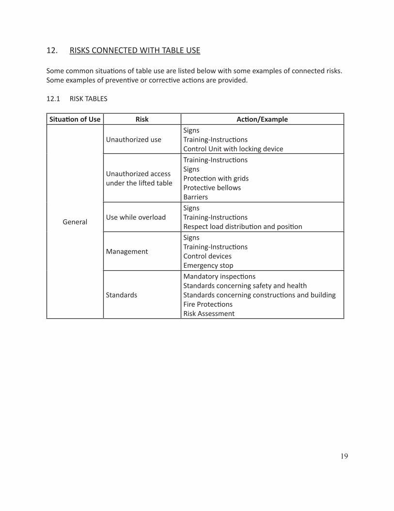
12. RISKS CONNECTED WITH TABLE USE
Some common situations of table use are listed below with some examples of connected risks. Some examples of preventive or corrective actions are provided.
12.1 RISK TABLES
Situation of Use Risk Action/Example
General
Unauthorized useSignsTraining-InstructionsControl Unit with locking device
Unauthorized access under the lifted table
Training-InstructionsSignsProtection with gridsProtective bellowsBarriers
Use while overloadSignsTraining-InstructionsRespect load distribution and position
Management
SignsTraining-InstructionsControl devicesEmergency stop
Standards
Mandatory inspectionsStandards concerning safety and healthStandards concerning constructions and building Fire ProtectionsRisk Assessment

20
Situation of Use Risk Action/Example
Environmental Fac-tors
Cold Type of oil limits for minimum temperatureGasket and pipe material
Hot Type of hydraulic fluid limits for maximum temperatureGasket and pipe material
Fire Type of hydraulic fluid (water, glycol no non-flame propagating oil) limits for maximum temperature
Explosion Hazard EEX componentsATEX directive
Environmental Risks
Biodegradable oil
Supplies Food grade hydraulic fluids surface treatment resistant to detergents
Humidity Class of electrical protection (IP) Anticorrosion protection (surface treatment, bushings, cylinders)
Dust Class of electrical protection (IP) Protection of mechanical parts, control unit and electric motor.
External Use Weather conditionsWin
13. SPARE PARTS
13.1 METHOD FOR REQUESTING SPARE PARTS
The tables are designed and built so that they do not require, if used correctly and suitable maintenance is performed as described in this manual, spare parts due to faults and breakage. Some parts subjected to wear are identified in the spare parts list attached to this manual. It is mandatory that only original spare parts are used, requesting them directly from Lift Products. The use of non-original spare parts invalidates the warranty and could jeopardise the proper operation of the table.
13.2 ORDERING SPARE PARTS
When ordering spare parts, always indicate the data specified on the machine plate.
14. DISPOSAL SCRAPING
If the table is to be scrapped, its parts must be disposed of separately according to their different types (e.g. metals, oils and lubricants, plastic and rubber etc.), using if possible special companies authorized for the purpose and in any case in compliance with what is specified by laws concerning the disposal of solid industrial waste.
21
22
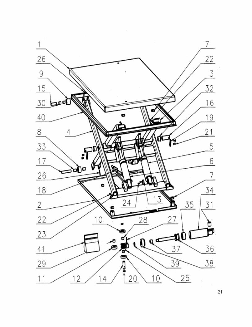
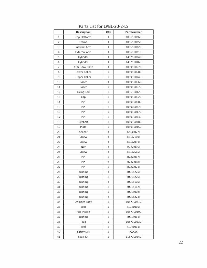
Parts List for LPBL-20-2-LSDescription Qty Part Number
1 Top Platform 1 108610036C
2 Frame 1 108610035C
3 Internal Arm 1 108610022C
4 External Arm 1 108610021C
5 Cylinder 1 148710024C
6 Cylinder 1 148710016C
7 Arm Hook Plate 4 108910057C
8 Lower Roller 2 108910058C
9 Upper Roller 2 108910074C
10 Roller 4 108910066C
11 Roller 2 108910067C
12 Fixing Rod 2 108610012C
13 Cap 2 108910062C
14 Pin 2 108910068C
15 Pin 2 108900037C
16 Pin 2 108910017C
17 Pin 2 108910073C
18 Eyebolt 2 108910078C
19 Plate 2 108910015C
20 Seeger 4 42038077T
21 Screw 4 44047169T
22 Screw 4 44047091T
23 Nut 4 45058005T
24 Screw 4 44047565T
25 Pin 2 46063017T
26 Pin 4 46063018T
27 Pin 2 46063021T
28 Bushing 4 40015225T
29 Bushing 2 40015226T
30 Bushing 4 40015105T
31 Bushing 2 40015112T
32 Bushing 2 40015002T
33 Bushing 4 40015224T
34 Cylinder Body 2 108710021C
35 Seal 2 41041016T
36 Rod-Piston 2 108710019C
37 Bushing 2 40015061T
38 Plug 2 108710023C
39 Seal 2 41041011T
40 Safety List 2 XXXXX
41 Seals Kit 2 118710024C
23
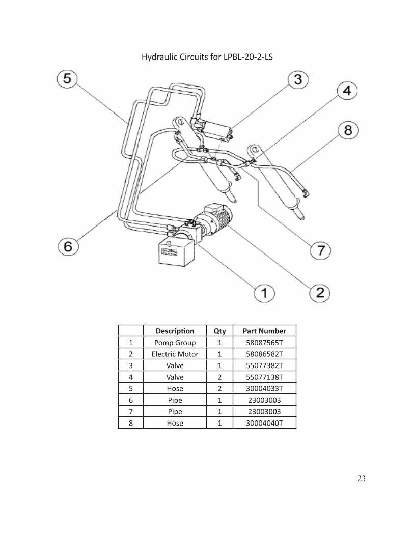
Description Qty Part Number1 Pomp Group 1 58087565T2 Electric Motor 1 58086582T3 Valve 1 55077382T4 Valve 2 55077138T5 Hose 2 30004033T6 Pipe 1 230030037 Pipe 1 230030038 Hose 1 30004040T
Hydraulic Circuits for LPBL-20-2-LS
24
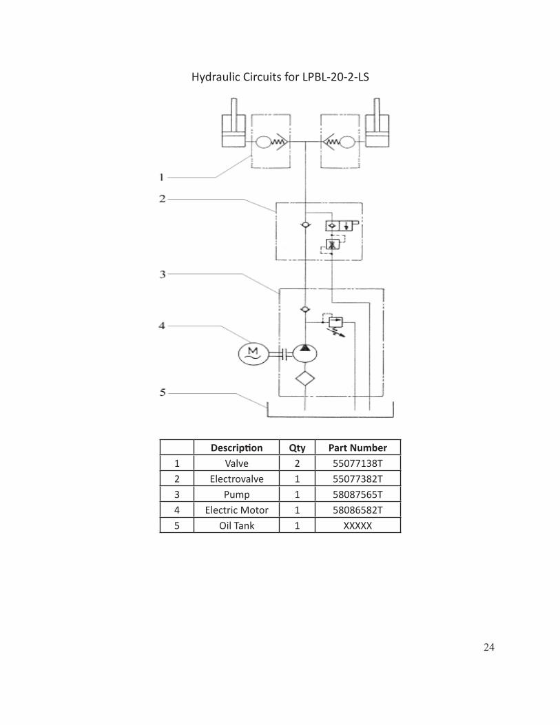
Description Qty Part Number1 Valve 2 55077138T2 Electrovalve 1 55077382T3 Pump 1 58087565T4 Electric Motor 1 58086582T5 Oil Tank 1 XXXXX
Hydraulic Circuits for LPBL-20-2-LS
25
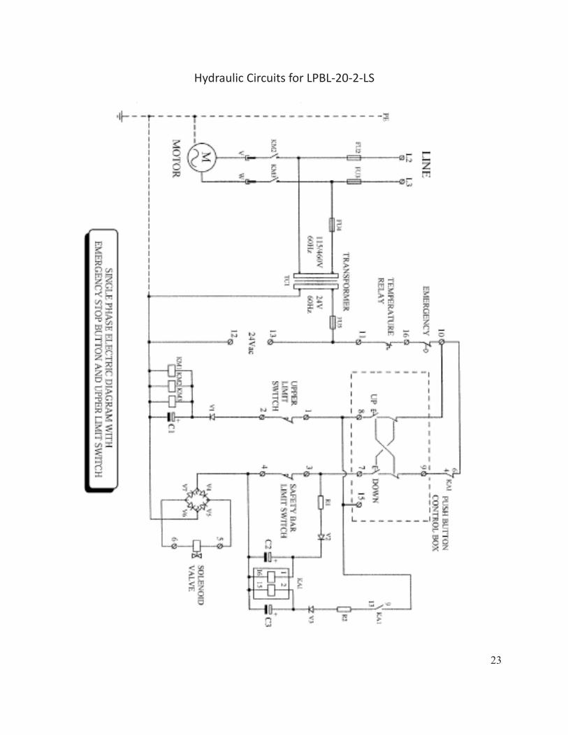
Hydraulic Circuits for LPBL-20-2-LS
23