Embed Size (px)
Citation preview

Guida Tecnica:Regolatori
Technical Guide:Regulators
E309573

2
3
INDICE 1) REGOLATORE ELETTRONICO S.R.7 E S.R.7-H400 1.1) Principio di funzionamento 1.1.1) Blocco funzionale 1.1.2) Riferimento 1.1.3) Amplificatore di errore 1.1.4) Rete di stabilità 1.1.5) Modulatore di larghezza di impulso 1.1.6) Sensing 1.2) Blocco di protezione 1.2.1) Protezione di bassa frequenza 1.2.2) Protezione di sovraccarico 1.2.3) Autoeccitazione 1.2.4) Connessione ai morsetti 1.2.5) Collegamenti possibili 1.2.6) Funzione dei potenziometri del regolatore 1.3) PROCEDURE DI COLLAUDO 1.3.1) Procedura di collaudo a banco 1.3.2) Procedura di collaudo su macchina 2) REGOLATORE ELETTRONICO U.V.R.6 E U.V.R.6-
H400 2.1) Caratteristiche generali 2.2) Caratteristiche tecniche 2.2.1) Alimentazione 2.2.2) Sensing 2.3) Regolazioni 2.3.1) Precisione della tensione 2.3.2) Regolazione della tensione 2.3.3) Regolazione del tempo di risposta in transitorio 2.4) Protezioni 2.5) Campo di utilizzazione 2.6) Autoeccitazione 2.7) PROCEDURE DI COLLAUDO 2.7.1) Procedura di collaudo a banco 2.7.2) Procedura di collaudo su macchina 2.8) Sostituzione di regolatori elettronici fuori produzione 2.8.1) Sostituzione del regolatore RT80 2.8.2) Sostituzione del regolatore RT80A 2.8.3) Sostituzione del regolatore RT83 2.8.4) Sostituzione del regolatore RT83B 3) SEGNALATORE PROTEZIONI A DISTANZA S.P.D.96/A
3.1) Caratteristiche generali 3.2) Cablaggio e accensione 3.3) Intervento delle protezioni dell’UVR6 3.4) Taratura dell’allarme di sovratensione
INDEX 1) S.R.7 AND S.R.7-H400 ELECTRONIC REGULATOR 1.1) Operation principle 1.1.1) Functional block 1.1.2) Reference 1.1.3) Error amplifier 1.1.4) Stability network 1.1.5) Impulse width modulator 1.1.6) Sensing 1.2) Protection block 1.2.1) Low frequency protection 1.2.2) Overload protection 1.2.3) Self-excitation 1.2.4) Terminals connection 1.2.5) Possible connections 1.2.6) Regulator potentiometer function 1.3) TEST PROCEDURES 1.3.1) Workbench test procedure 1.3.2) Machine test procedure 2) U.V.R.6 AND U.V.R.6-H400 ELECTRONIC REGULA-
TOR 2.1) General characteristics 2.2) Technical characteristics 2.2.1) Supply 2.2.2) Sensing 2.3) Regulations 2.3.1) Voltage precision 2.3.2) Voltage regulation 2.3.3) Transient reply time adjustment 2.4) Protections 2.5) Usage field 2.6) Self-excitation 2.7) TEST PROCEDURES 2.7.1) Workbench test procedure 2.7.2) Machine test procedure 2.8) Replacing electronic regulators that are no longer produced 2.8.1) Replacing the RT80 regulator 2.8.2) Replacing the RT80A regulator 2.8.3) Replacing the RT83 regulator 2.8.4) Replacing the RT83B regulator 3) S.P.D.96/A REMOTE PROTECTION SIGNALLER
3.1) General characteristics 3.2) Wiring and start-up 3.3) UVR6 protection intervention 3.4) Calibrating the overvoltage alarm
4
1) REGOLATORE ELETTRONICO S.R.7 E S.R.7-H400 1.1) PRINCIPIO DI FUNZIONAMENTO
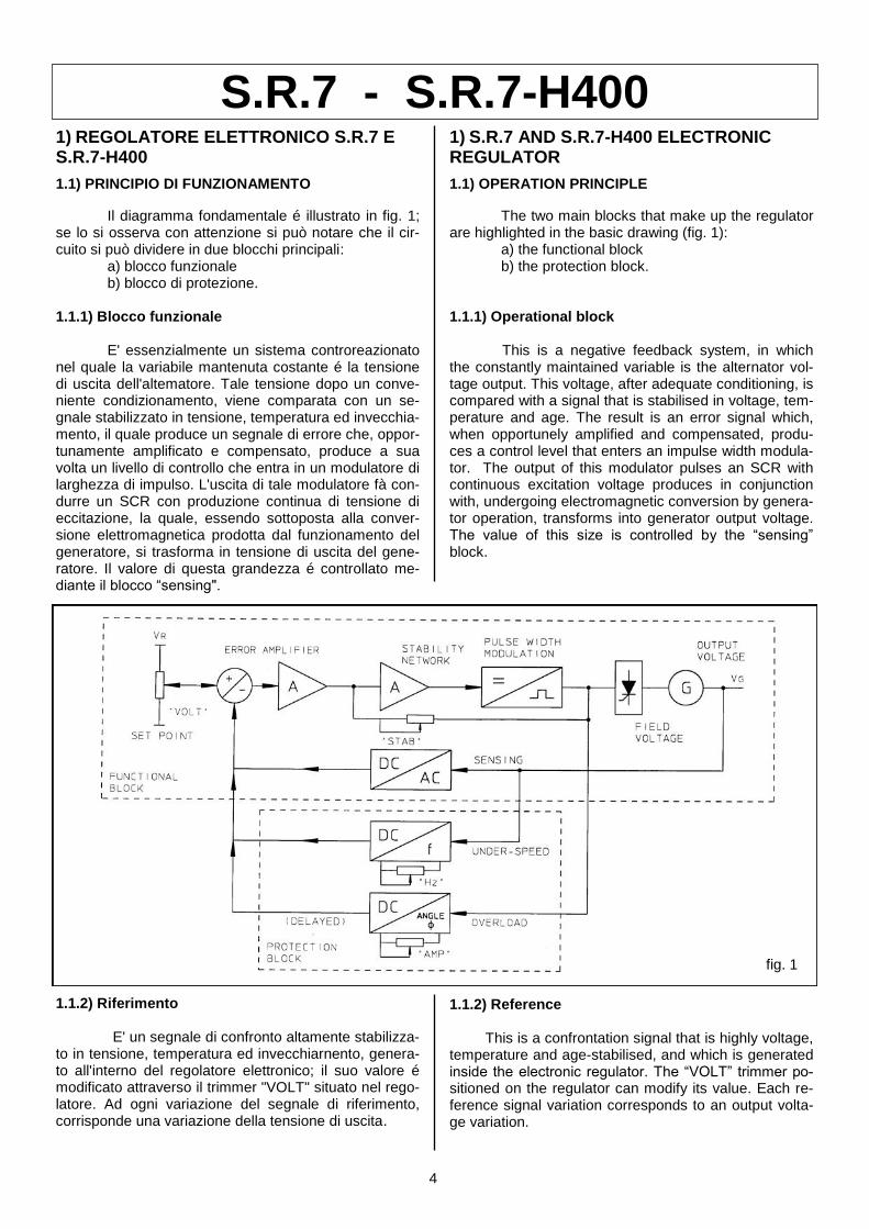
Il diagramma fondamentale é illustrato in fig. 1; se lo si osserva con attenzione si può notare che il cir-cuito si può dividere in due blocchi principali: a) blocco funzionale b) blocco di protezione. 1.1.1) Blocco funzionale
E' essenzialmente un sistema controreazionato nel quale la variabile mantenuta costante é la tensione di uscita dell'altematore. Tale tensione dopo un conve-niente condizionamento, viene comparata con un se-gnale stabilizzato in tensione, temperatura ed invecchia-mento, il quale produce un segnale di errore che, oppor-tunamente amplificato e compensato, produce a sua volta un livello di controllo che entra in un modulatore di larghezza di impulso. L'uscita di tale modulatore fà con-durre un SCR con produzione continua di tensione di eccitazione, la quale, essendo sottoposta alla conver-sione elettromagnetica prodotta dal funzionamento del generatore, si trasforma in tensione di uscita del gene-ratore. Il valore di questa grandezza é controllato me-diante il blocco “sensing".
1) S.R.7 AND S.R.7-H400 ELECTRONIC REGULATOR 1.1) OPERATION PRINCIPLE
The two main blocks that make up the regulator are highlighted in the basic drawing (fig. 1): a) the functional block b) the protection block. 1.1.1) Operational block This is a negative feedback system, in which the constantly maintained variable is the alternator vol-tage output. This voltage, after adequate conditioning, is compared with a signal that is stabilised in voltage, tem-perature and age. The result is an error signal which, when opportunely amplified and compensated, produ-ces a control level that enters an impulse width modula-tor. The output of this modulator pulses an SCR with continuous excitation voltage produces in conjunction with, undergoing electromagnetic conversion by genera-tor operation, transforms into generator output voltage. The value of this size is controlled by the “sensing” block.
1.1.2) Riferimento E' un segnale di confronto altamente stabilizza-to in tensione, temperatura ed invecchiarnento, genera-to all'interno del regolatore elettronico; il suo valore é modificato attraverso il trimmer "VOLT" situato nel rego-latore. Ad ogni variazione del segnale di riferimento, corrisponde una variazione della tensione di uscita.
fig. 1
1.1.2) Reference This is a confrontation signal that is highly voltage, temperature and age-stabilised, and which is generated inside the electronic regulator. The “VOLT” trimmer po-sitioned on the regulator can modify its value. Each re-ference signal variation corresponds to an output volta-ge variation.
S.R.7 - S.R.7-H400
5
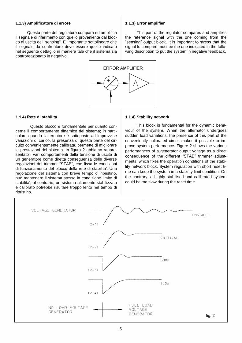
1.1.3) Error amplifier
This part of the regulator compares and amplifies the reference signal with the one coming from the “sensing” output block. It is important to stress that the signal to compare must be the one indicated in the follo-wing description to put the system in negative feedback.
1.1.4) Stability network This block is fundamental for the dynamic beha-
viour of the system. When the alternator undergoes
sudden load variations, the presence of this part of the
conveniently calibrated circuit makes it possible to im-
prove system performance. Figure 2 shows the various
performances of a generator output voltage as a direct
consequence of the different “STAB” trimmer adjust-
ments, which fixes the operation conditions of the stabi-
lity network block. System regulation with short reset ti-
me can keep the system in a stability limit condition. On
the contrary, a highly stabilised and calibrated system
could be too slow during the reset time.
1.1.3) Amplificatore di errore Questa parte del regolatore compara ed amplifica
il segnale di riferimento con quello proveniente dal bloc-co di uscita del "sensing". E' importante sottolineare che il segnale da confrontare deve essere quello indicato nel seguente dettaglio in maniera tale che il sistema sia controreazionato in negativo.
1.1.4) Rete di stabilitá Questo blocco é fondamentale per quanto con-cerne il comportamento dinamico del sistema; in parti-colare quando l'alternatore é sottoposto ad improvvise variazioni di carico, la presenza di questa parte del cir-cuito convenientemente calibrata, permette di migliorare le prestazioni del sistema. In figura 2 abbiamo rappre-sentato i vari comportamenti della tensione di uscita di un generatore come diretta conseguenza delle diverse regolazioni del trimmer "STAB", che fissa le condizioni di funzionamento del blocco della rete di stabilita'. Una regolazione del sistema con breve tempo di ripristino, può mantenere il sistema stesso in condizione limite di stabilita'; al contrario, un sistema altamente stabilizzato e calibrato potrebbe risultare troppo lento nel tempo di ripristino.
fig. 2
6
1.1.5) Modulatore di larghezza di impulso Questa parte del regolatore elettronico ha il compito di trasformare il segnale di controllo in rispettivi impulsi che pilotano gli SCR di potenza in modo tale da cambiare il valore della tensione continua di eccitazione del generatore. 1.1.6) Sensing In questa parte del circuito la tensione di uscita dell'alternatore é adeguatamente condizionata e appli-cata ad un convertitore AC/DC il cui segnale di uscita viene comparato con quello di riferimento.
1.2) Blocco di protezione Con riferimento alla figura 1 appare evidente che la parte del regolatore elettronico denominata bloc-co di protezione é costituita da due parti:
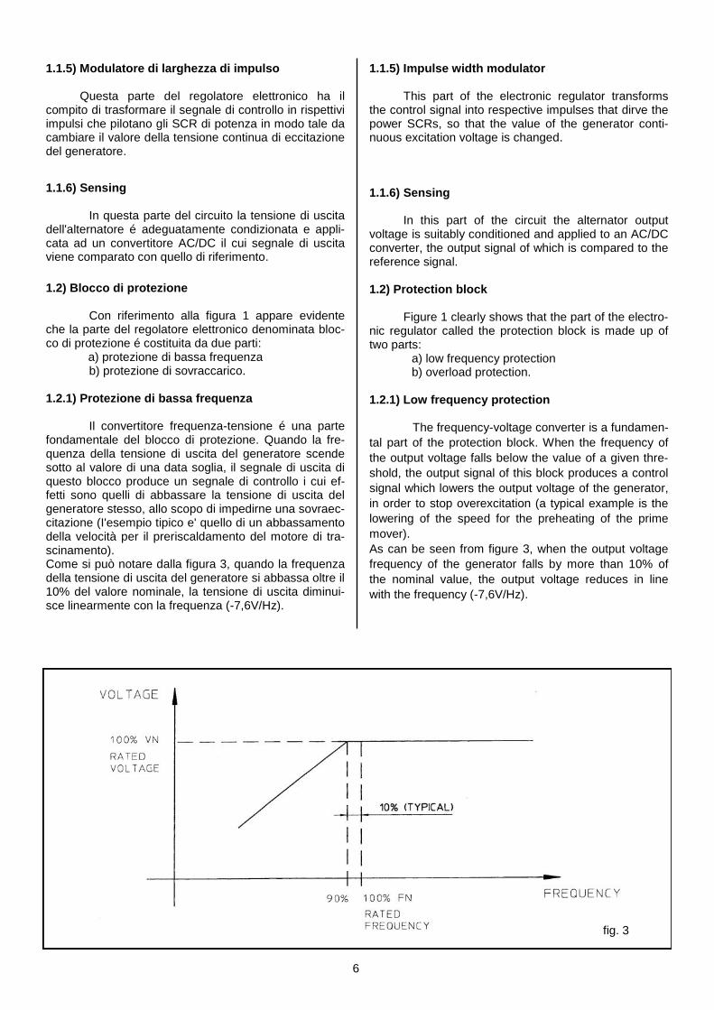
a) protezione di bassa frequenza b) protezione di sovraccarico. 1.2.1) Protezione di bassa frequenza Il convertitore frequenza-tensione é una parte fondamentale del blocco di protezione. Quando la fre-quenza della tensione di uscita del generatore scende sotto al valore di una data soglia, il segnale di uscita di questo blocco produce un segnale di controllo i cui ef-fetti sono quelli di abbassare la tensione di uscita del generatore stesso, allo scopo di impedirne una sovraec-citazione (I'esempio tipico e' quello di un abbassamento della velocità per il preriscaldamento del motore di tra-scinamento). Come si può notare dalla figura 3, quando la frequenza della tensione di uscita del generatore si abbassa oltre il 10% del valore nominale, la tensione di uscita diminui-sce linearmente con la frequenza (-7,6V/Hz).
fig. 3
1.1.5) Impulse width modulator This part of the electronic regulator transforms the control signal into respective impulses that dirve the power SCRs, so that the value of the generator conti-nuous excitation voltage is changed. 1.1.6) Sensing In this part of the circuit the alternator output voltage is suitably conditioned and applied to an AC/DC converter, the output signal of which is compared to the reference signal. 1.2) Protection block Figure 1 clearly shows that the part of the electro-nic regulator called the protection block is made up of two parts:
a) low frequency protection b) overload protection. 1.2.1) Low frequency protection The frequency-voltage converter is a fundamen-
tal part of the protection block. When the frequency of
the output voltage falls below the value of a given thre-
shold, the output signal of this block produces a control
signal which lowers the output voltage of the generator,
in order to stop overexcitation (a typical example is the
lowering of the speed for the preheating of the prime
mover).
As can be seen from figure 3, when the output voltage
frequency of the generator falls by more than 10% of
the nominal value, the output voltage reduces in line
with the frequency (-7,6V/Hz).
7
La funzione del trimmer "Hz" é quella di aggiustare la soglia di intervento della protezione. Per i regolatori elettronici di normale produzione, detta soglia é pretara-ta intorno al meno 10% del valore della frequenza nomi-nale. 1.2.2) Protezione di sovraccarico
Questa parte del circuito del regolatore elettroni-
co ha la funzione di proteggere l'alternatore dalla possi-bilitá di una sovraeccitazione. Quando il valore della tensione continua che alimenta I'induttore dell'alternato-re, é più alto di quello fissato dalla soglia stabilita me-diante il trimmer "AMP.", un segnale in continua, ritarda-to nel tempo, fà abbassare il valore della tensione di uscita dell'alternatore e limita la corrente di eccitazione prodotta dall'induttore, garantendo dei margini di sicu-rezza al funzionamento del sistema. Il ritardo nell'inter-vento di tale protezione permette il temporaneo sovrac-carico dell'alternatore senza che la tensione di uscita diminuisca; normalmente tale ritardo é di circa 15-20 se-condi, sufficiente a garantire, per esempio, l'avviamento di motori.
1.2.3) Autoeccitazione
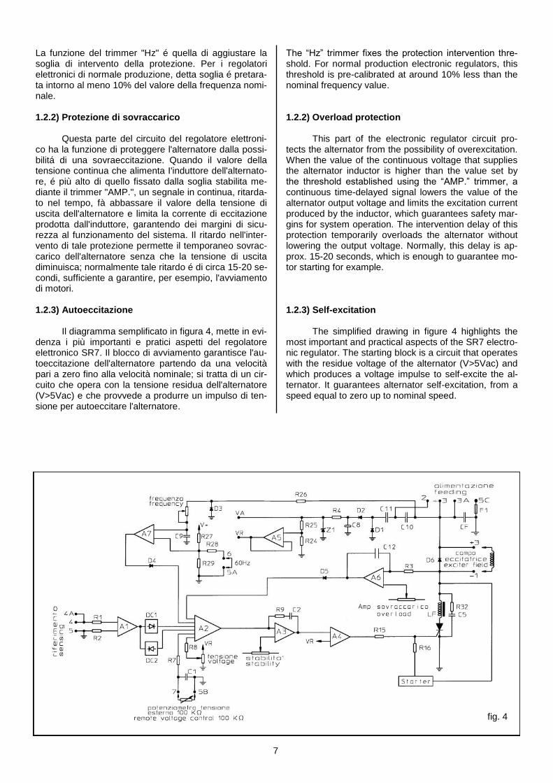
Il diagramma semplificato in figura 4, mette in evi-
denza i più importanti e pratici aspetti del regolatore elettronico SR7. Il blocco di avviamento garantisce l'au-toeccitazione dell'alternatore partendo da una velocità pari a zero fino alla velocità nominale; si tratta di un cir-cuito che opera con la tensione residua dell'alternatore (V>5Vac) e che provvede a produrre un impulso di ten-sione per autoeccitare l'alternatore.
fig. 4
The “Hz” trimmer fixes the protection intervention thre-shold. For normal production electronic regulators, this threshold is pre-calibrated at around 10% less than the nominal frequency value. 1.2.2) Overload protection
This part of the electronic regulator circuit pro-tects the alternator from the possibility of overexcitation. When the value of the continuous voltage that supplies the alternator inductor is higher than the value set by the threshold established using the “AMP.” trimmer, a continuous time-delayed signal lowers the value of the alternator output voltage and limits the excitation current produced by the inductor, which guarantees safety mar-gins for system operation. The intervention delay of this protection temporarily overloads the alternator without lowering the output voltage. Normally, this delay is ap-prox. 15-20 seconds, which is enough to guarantee mo-tor starting for example. 1.2.3) Self-excitation
The simplified drawing in figure 4 highlights the most important and practical aspects of the SR7 electro-nic regulator. The starting block is a circuit that operates with the residue voltage of the alternator (V>5Vac) and which produces a voltage impulse to self-excite the al-ternator. It guarantees alternator self-excitation, from a speed equal to zero up to nominal speed.
8
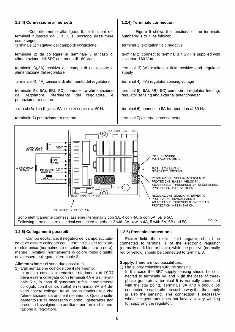
1.2.4) Connessione ai morsetti Con riferimento alla figura 5, le funzioni dei terminali numerati da 1 a 7, si possono riassumere come segue : terminale 1) negativo del campo di eccitazione terminale 2) da collegare al terminale 3 in caso di alimentazione dell'SR7 con meno di 160 Vac. terminale 3),3A) positivo del campo di eccitazione e alimentazione del regolatore terminale 4), 4A) tensione di riferimento del regolatore terminale 5), 5A), 5B), 5C) comune tra alimentazione del regolatore, riferimento del regolatore, e potenziometro esterno terminale 6) da collegare a 5A per funzionamento a 60 Hz terminale 7) potenziometro esterno.
1.2.5) Collegamenti possibili Campo eccitatrice: il negativo del campo eccitatri-ce deve essere collegato con il terminale 1 del regolato-
re elettronico (normalmente di colore blu scuro o nero), mentre il positivo (normalmente di colore rosso o giallo) deve essere collegato al terminale 3. Alimentazione : ci sono due possibilitá. 1) L'alimentazione coincide con il riferimento.
In questo caso l'alimentazione-riferimento dell'SR7 deve essere collegata con i terminali 4A e 5 (il termi-nale 5 é, in caso di generatori trifasi, normalmente collegato con il centro stella) e i terminali 3A e 4 de-vono essere collegati tra di loro in maniera tale che l'alimentazione sia anche il riferimento. Questo colle-gamento risulta necessario quando il generatore non presenta l'avvolgimento ausiliario per fornire l'alimen-tazione al regolatore.
fig. 5
1.2.4) Terminals connection Figure 5 shows the functions of the terminals numbered 1 to 7, as follows: terminal 1) excitation field negative terminal 2) connect to terminal 3 if SR7 is supplied with less than 160 Vac. terminal 3),3A) excitation field positive and regulator supply terminal 4), 4A) regulator sensing voltage terminal 5), 5A), 5B), 5C) common to regulator feeding, regulator sensing and external potentiometer terminal 6) connect to 5A for operation at 60 Hz terminal 7) external potentiometer.
1.2.5) Possible connections Exciter field: the exciter field negative should be connected to terminal 1 of the electronic regulator (normally dark blue or black), while the positive (normally red or yellow) should be connected to terminal 3.
Supply: There are two possibilities. 1) The supply coincides with the sensing. In this case the SR7 supply-sensing should be con-
nected to terminals 4A and 5 (in the case of three-phase generators, terminal 5 is normally connected with the star point). Terminals 3A and 4 should be connected to each other in such a way that the supply is also the sensing. This connection is necessary when the generator does not have auxiliary winding for supplying the regulator.
Sono elettricamente connessi assieme i terminali 3 con 3A, 4 con 4A, 5 con 5A, 5B e 5C. Following terminals are electrical connected together : 3 with 3A, 4 with 4A, 5 with 5A, 5B and 5C
9
2) L'alimentazione ed il riferimento sono separati. Questo é il caso di un generatore provvisto di avvol-gimento ausiliario per l'alimentazione del regolatore; l'alimentazione và sempre collegata ai terminali 3A (o 3) e 5C (o 5, 5A, 5B) del regolatore.
In entrambi i casi (1 e 2) l'alimentazione dell'SR7 puo' variare tra 80 e 270 Vac, ma occorre considerare che nel caso di alimentazione con tensione tra 80 e 160 Vac, i terminali 2 e 3 devono essere ponticellati, mentre nel caso di tensione tra 160 e 270 Vac, gli stessi termi-nali devono essere lasciati aperti. Riferimento: deve essere collegato ai terminali 4A e 5 e può variare tra 80 e 350 Vac. Il riferimento é solo mo-nofase e perciò é normalmente collegato ad una fase dell'alternatore. Funzionamento a 60 Hz (SR7): al fine di mantenere correttamente regolata la protezione di bassa frequen-za, in caso di funzionamento a 60 Hz, é necessario che i terminali 5A e 6 siano collegati tra di loro. Potenziometro esterno: è possibile ottenere la regola-zione della tensione in un range di ± 5% inserendo, nei terminali 5B e 7, un potenziometro da 100KΩ (per le macchine a 6 morsetti) o un potenziometro da 100KΩ con in serie una resistenza da 100KΩ (per le macchine a 12 morsetti).
1.2.6) Funzione dei potenziometri del regolatore “VOLT”
Questo potenziometro permette di regolare la tensione generata dall'alternatore in maniera molto semplice: ruotando la vite in senso orario la tensione aumenta, mentre ruotando in senso antiorario diminuisce. "STAB"
Questo potenziometro ottimizza le prestazioni dell'alter-natore. Ruotando in senso orario la stabilità diminuisce: il tempo di risposta diminuisce ma la tensione tende ad essere meno stabile. Ruotando in senso antiorario, il tempo di risposta aumenta e la tensione tende ad esse-re più stabile. Al fine di regolare correttamente questo potenziometro, suggeriamo a seguito un sistema molto semplice per ottenere quanto detto: il generatore deve funzionare, partendo da una condizione di vuoto, con il potenziome-tro in posizione di massima stabilita' (totalmente ruotato in senso antiorario); lentamente si ruota in senso orario fino a notare una oscillazione della luce generata da una lampada a filamento collegata all'uscita del genera-tore. A questo punto si ruota lentamente lo stesso po-tenziometro in senso antiorario fino a notare la stabiliz-zazione della luce generata. "Hz"
Questo potenziometro che permette di regolare I'inter-vento della protezione di bassa frequenza, é normal-mente pretarato e quindi sigillato dal costruttore. Per ritarare questa protezione é necessario portare il generatore alle condizioni normali di vuoto, ruotare il po-tenziometro in senso orario fino alla posizione limite, di-minuire successivamente la velocita' nominale del 10% ed infine ruotare il potenziometro in senso antiorario fin-
2) The supply and sensing are separate. This is the case of a generator equipped with auxilia-
ry winding for regulator supply. Supply is always con-nected to terminals 3A (or 3) and 5C (or 5, 5A, 5B) of the regulator.
In both these cases (1 and 2) the SR7 supply can vary from 80 to 270 Vac. But it should be noted that termi-nals 2 and 3 should be bridged for supply with voltage between 80 and 160 Vac, while the same terminals should be left open if the voltage is between 160 and 270 Vac. Sensing: should be connected to terminals 4A and 5 and can vary from between 80 to 350 Vac. The sensing is single phase only and therefore normally connected to one alternator phase. Operation at 60 Hz: When operating at 60 Hz, termi-nals 5A and 6 should be connected to each other in or-der to keep the low frequency protection correctly regu-lated. External potentiometer: it is possible to get a remote voltage regulation of ± 5% inserting, in the terminals 5B and 7, a 100KΩ potentiometer (for the 6 lead units) or a 100KΩ potentiometer with a 100KΩ resistance in series (for the 12 lead units).
1.2.6) Functions of the regulator potentiometers “VOLT” With this potentiometer it is possible to adjust the volta-ge generated by the alternator in a very simple way: if the screw is turned clockwise the voltage increases, if turned anticlockwise it decreases. "STAB" This potentiometer optimises alternator performance. If turned clockwise the stability decreases, i.e. the respon-se time decreases but the voltage tends to be less sta-ble. If turned anticlockwise, the response time increases and the voltage tends to be more stable. In order to adjust this potentiometer correctly, we advise using the very simple method given below. The genera-tor must be working, starting from zero load, and the po-tentiometer must be at maximum stability (turned fully anticlockwise). Slightly turn clockwise until you notice that the light generated by the filament lamp oscillates. At this point, turn the potentiometer slowly anticlockwise until the light stabilises. "Hz"
With this potentiometer, which is normally pre-calibrated then sealed by the producer, it is possible to adjust the low frequency protection intervention. To recalibrate this protection, you must take the genera-tor to a normal zero load condition, turn the potentiome-ter clockwise until the limit position is reached, then de-crease the nominal speed by 10%. After this turn the potentiometer anticlockwise and measure the voltage
10
tanto che, misurando il valore della tensione si ottiene una diminuzione di 5V.
Questo significa che quando la velocità diminuisce più
del 10% del valore nominale, anche la tensione diminui-
sce proporzionalmente, impedendo il surriscaldamento
del generatore. Anche se raccomandiamo la taratura di
tale protezione al 10% del valore nominale, é ovviamen-
te possibile tarare la soglia su altri valori.
“AMP”
Questo potenziometro permette di regolare il livello di
intervento della protezione di sovraccarico. Tale sistema
di protezione ha un ritardo di intervento che permette un
sovraccarico temporaneo, necessario per esempio per
l'avviamento di motori o applicazioni simili.
Per modificare questa protezione é necessario
sovraccaricare il generatore di un 15% rispetto al carico
nominale, ruotare il potenziometro fino alla minima
posizione (verso antiorario), attendere circa venti
secondi entro i quali il valore della tensione decresce e
in queste condizioni, ruotando il potenziometro in senso
orario, fissare il valore della tensione del generatore ad
un 10% in meno di quello nominale. A questo punto,
togliendo il sovraccarico iniziale, il valore della tensione
aumenta fino a riportarsi al suo valore nominale.
Fusibile
Il regolatore elettronico SR7 é dotato di un fusibile che
protegge l'alternatore da sovrariscaldamenti in caso di
malfunzionamento del regolatore stesso; la sostituzione
può essere eseguita con facilità ma si raccomanda che
il nuovo fusibile abbia le stesse caratteristiche di quello
da sostituire (250V - 5A, rapido tipo F).
value until it has decreased by 5V.
When the speed decreases by more than 10% of the nominal value, the voltage also decreases proportionally, blocking generator overheating. Even if we advise calibrating this protection at 10% of the nominal value, it is obviously possible to calibrate the threshold at other values. “AMP”
With this potentiometer it is possible to adjust the
intervention level of the overload protection. This
protection system has an intervention delay, which
permits a temporary overload, necessary for example
when starting motors or similar applications.
To modify this protection you must overload the
generator by 15% of the nominal load, turn the
potentiometer to minimum (anticlockwise) and wait
about twenty seconds. During this period of time the
voltage value decreases. In this condition and while
turning the potentiometer clockwise, fix the generator
voltage value at 10% less than the nominal one. At this
point, while the initial overload is being removed, the
voltage increases to the nominal value.
Fuse The SR7 electronic regulator is equipped with a fuse, which protects the alternator from overheating in cases of regulator malfunction. The fuse can be replaced easily, but the new one must have the same characteristics as the one being replaced (250V-5A, quick acting, F type).

11
fig. 6
1.3) PROCEDURE DI COLLAUDO 1.3.1) Procedura di collaudo a banco (SR7) 1) predisporre il regolatore collegato come in figura 6.
2) prima di alimentare il circuito ruotare i potenziometri "VOLT" e "STAB" fino alla posizione limite in senso an-tiorario, mentre i potenziometri "Hz" e "Amp" fino alla posizione limite in senso orario ; posizionare la regola-zione del variac in corrispondenza del valore minimo. 3) accendere il variac e, aumentando lentamente il valo-re della tensione, verificare che la lampada si accenda e immediatamente si spenga ; portarsi con il valore della tensione a circa 200 Vac. La lampada dovrebbe rimane-re spenta. 4) ruotando lentamente il trimmer "VOLT" in senso ora-rio, si dovrebbe notare che I'intensità della luce emessa dalla lampada varia da un minimo ad un massimo: ripor-tare il potenziometro "VOLT" in posizione di minimo. 5) portare il trimmer "STAB" in posizione di massimo e ripetere le operazioni del punto 4; si dovrebbe notare che la variazione dell'intensità della luce dovuta alla re-golazione sul trimmer "VOLT", è più rapida. Riportare i trimmer "STAB" e "VOLT" in posizione di minimo. 6) ruotare il potenziometro "VOLT" in posizione di mas-simo (senso orario); la lampada emetterà la massima intensità di luce; ruotando il trimmer "AMP" in posizione di minimo (senso antiorario) e attendendo circa venti se-condi, la protezione di sovraccarico interviene facendo spegnere la lampada. Dopo un istante la lampada si riaccenderà. 7) ruotare lentamente il trimmer "AMP" verso la posizio-ne di massimo e controllare che la lampada si accenda con intensità massima; riportare il trimmer "VOLT" in posizione di minimo.
1.3) TEST PROCEDURES 1.3.1) Workbench test procedure (SR7) 1) Prepare the connected regulator as shown in figure 6.
2) Before supplying the circuit with current, turn the "VOLT" and "STAB" potentiometers anticlockwise and the "Hz" and "Amp" potentiometers clockwise to their relevant limits. Position the variac adjustment in corre-spondence with the minimum value. 3) Switch on the variac and, while slowly increasing the voltage value, make sure that the light switches on and then immediately off. When a voltage of around 200 Vac is reached the light should remain off. 4) If the “VOLT” trimmer is turned slowly clockwise, you should note that the intensity of the light varies from mi-nimum to maximum. Take the “VOLT” potentiometer back to the minimum position. 5) Take the "STAB" trimmer to maximum and repeat point 4. You should note that the light intensity variation caused by the “VOLT” trimmer adjustment is quicker. Take the "STAB" and "VOLT" trimmers to minimum. 6) If the "VOLT" potentiometer is turned to maximum (clockwise) the light shines at maximum intensity. About 20 seconds after the “AMP” trimmer is turned to mini-mum (anticlockwise), the overload protection intervenes and switches off the light. The light should switch on again after a short period. 7) Slowly turn the "AMP" trimmer to maximum and check that the light switches on at maximum intensity. Take the “VOLT” trimmer back to minimum.
12
8) ruotare lentamente in senso orario il trimmer "VOLT" fino a portare la luce della lampada ad una intensità me-dia; ruotare il trimmer "Hz" in senso antiorario control-lando che la lampada si spenga. Portare il trimmer "Hz" in una posizione intermedia ed il trimmer "VOLT" in una posizione che permetta una intensità media della lam-pada; cortocircuitando i terminali 5 e 6, la lampada do-vrebbe spegnersi e successivamente ponticellando i ter-minali 5 e 7 la lampada dovrebbe accendersi con una intensità di luce massima Se, in tutte le prove sopracitate si riscontrano i compor-tamenti descritti, il regolatore in esame puo' considerarsi idoneo al funzionamento. 1.3.2) Procedura di collaudo su macchina (SR7 e
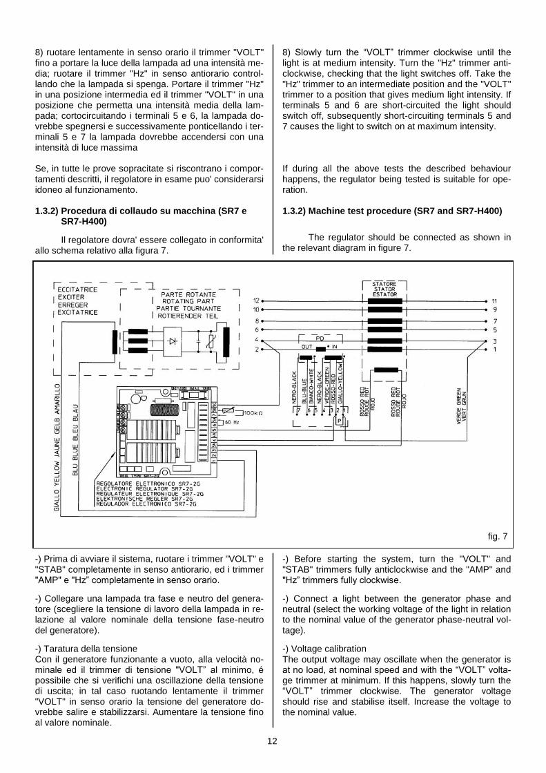
SR7-H400) Il regolatore dovra' essere collegato in conformita' allo schema relativo alla figura 7.
fig. 7
8) Slowly turn the “VOLT” trimmer clockwise until the light is at medium intensity. Turn the "Hz" trimmer anti-clockwise, checking that the light switches off. Take the "Hz" trimmer to an intermediate position and the "VOLT" trimmer to a position that gives medium light intensity. If terminals 5 and 6 are short-circuited the light should switch off, subsequently short-circuiting terminals 5 and 7 causes the light to switch on at maximum intensity. If during all the above tests the described behaviour happens, the regulator being tested is suitable for ope-ration. 1.3.2) Machine test procedure (SR7 and SR7-H400) The regulator should be connected as shown in the relevant diagram in figure 7.
-) Prima di avviare il sistema, ruotare i trimmer "VOLT" e "STAB" completamente in senso antiorario, ed i trimmer "AMP" e "Hz” completamente in senso orario. -) Collegare una lampada tra fase e neutro del genera-tore (scegliere la tensione di lavoro della lampada in re-lazione al valore nominale della tensione fase-neutro del generatore). -) Taratura della tensione Con il generatore funzionante a vuoto, alla velocità no-minale ed il trimmer di tensione "VOLT” al minimo, é possibile che si verifichi una oscillazione della tensione di uscita; in tal caso ruotando lentamente il trimmer "VOLT" in senso orario la tensione del generatore do-vrebbe salire e stabilizzarsi. Aumentare la tensione fino al valore nominale.
-) Before starting the system, turn the "VOLT" and "STAB" trimmers fully anticlockwise and the "AMP" and "Hz” trimmers fully clockwise. -) Connect a light between the generator phase and neutral (select the working voltage of the light in relation to the nominal value of the generator phase-neutral vol-tage). -) Voltage calibration The output voltage may oscillate when the generator is at no load, at nominal speed and with the “VOLT” volta-ge trimmer at minimum. If this happens, slowly turn the “VOLT” trimmer clockwise. The generator voltage should rise and stabilise itself. Increase the voltage to the nominal value.
13
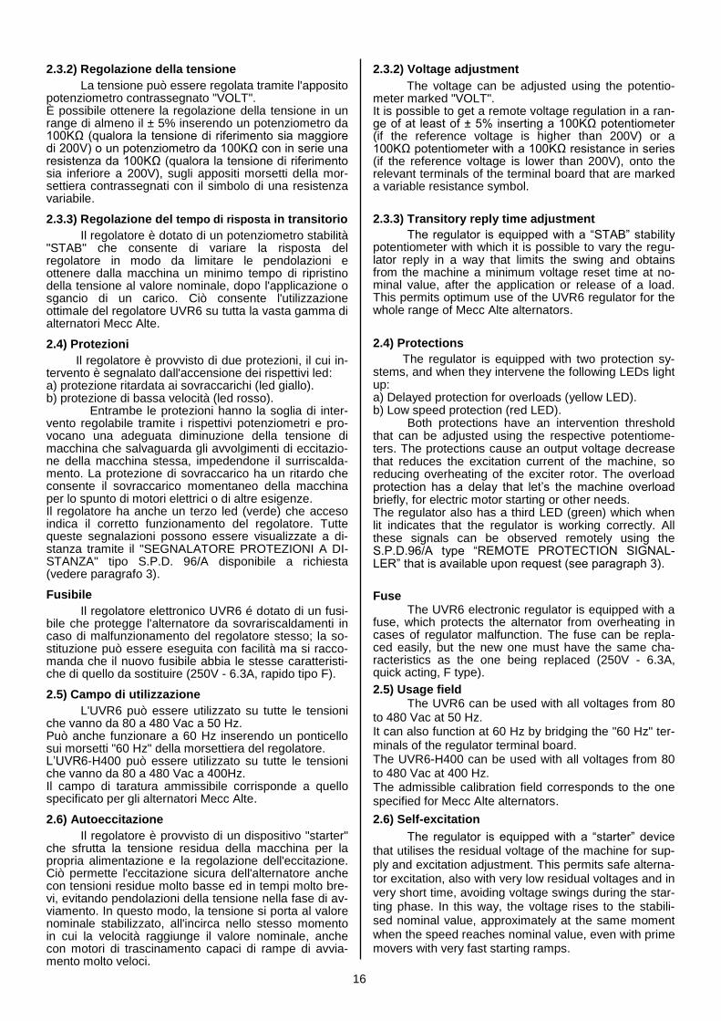
-) Taratura della stabilità Per aggiustare lo statismo del regolatore, girare lenta-mente il trimmer “STAB” in senso orario fino a notare che la lampada, collegata precedentemente tra fase e neutro, inizi a lampeggiare leggermente. A questo punto ruotare il trimmer "STAB" in senso antiorario, in modo che I'illuminazione della lampada diventi perfettamente stabile. -) Taratura protezione di sovraccarico Per aggiustare la protezione di sovraccarico "AMP", ap-plicare all'alternatore il carico nominale. Dopodichè di-minuire la velocità del 10% e ruotare il trimmer "AMP" completamente in senso antiorario. Dopo un intervallo di circa 15-20 secondi, si dovra' notare una diminuzione nel valore della tensione del generatore. In queste con-dizioni, ruotare lentamente il trimmer "AMP" in senso orario fino a portare il valore della tensione di uscita al 97% del valore nominale. Riportarsi alla velocità nomi-nale, e verificare che la tensione del generatore salga al valore nominale. Se ciò non avvenisse, ripetere la cali-brazione. -) Taratura protezione di bassa velocità Se la macchina deve funzionare a 60 Hz, assicurarsi che sia inserito il ponticello tra i morsetti "60 Hz" del re-golatore elettronico. Per aggiustare la protezione di bas-sa frequenza, far girare il generatore a una velocità pari al 90% di quella nominale. Agire lentamente sul trimmer "Hz” ruotandolo in senso antiorario affinchè la tensione del generatore inizi a diminuire. Aumentando la velocità, la tensione del generatore si dovrà normalizzare. Ripor-tare la velocità al valore nominale.
-) Per il collegamento del potenziometro esterno:
ATTENZIONE: quando si collega il potenziomentro esterno è necessario seguire la procedura sottoriportata per ottenere un corretto funzionamento della macchina. 1) Ruotare il trimmer “VOLT” nel regolatore elettronico completamente in senso antiorario. 2) Posizionare il potenziometro esterno a metà corsa e connetterlo agli appositi morsetti del regolatore. 3) Tramite il trimmer “VOLT” del regolatore tarare la ten-sione al valore nominale. Se, in tutte le prove sopracitate si riscontrano i compor-tamenti descritti, il regolatore in esame può considerarsi idoneo al funzionamento.
-) Stability calibration To adjust regulator stability, slowly turn the “STAB” trim-mer clockwise until the light that was previously con-nected between phase and neutral begins flashing slightly. Turn the “STAB” trimmer anticlockwise until the light becomes perfectly stable.
-) Overload protection calibration To adjust the “AMP” overload protection apply a nomi-nal load to the alternator then decrease the speed by 10% and turn the “AMP” trimmer fully anticlockwise. Af-ter a pause of 15-20 seconds, the generator voltage va-lue should decrease. In these conditions, slowly turn the “AMP” trimmer clockwise until the output voltage value is at 97% of the nominal value. When returning to nor-mal speed, the generator voltage return to nominal va-lue. If this does not happen, repeat the calibration.
-) Low speed protection calibration If the machine is to work at 60 Hz, make sure that the “60 Hz” terminals of the electronic regulator are bridged. To adjust the low frequency protection, make the gene-rator run at a speed that is equal to 90% of the nominal one. Slowly turn the “Hz” trimmer in an anticlockwise direction until the generator voltage begins to decrease. When the speed is increased, the generator voltage should normalise. Take the speed back to the nominal value.
-) Instructions to follow for the external potentiometer connection: CAUTION: in order to get a correct working of the ma-chine, it is necessary to follow the following procedure, connectring the external potentiometer.
1) Turn the “VOLT” trimmer of the electronic regulator completely anticlockwise. 2) Set the external potentiometer at half turn and con-nect it to the proper terminals of the regulator. 3) Adjust the voltage at the nominal value by the “VOLT” trimmer of the regulator. If during all the above tests the described behaviour happens, the regulator being examined is suitable for operation.
14
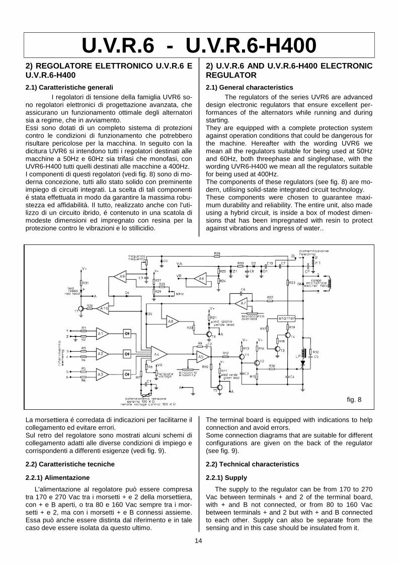
2) REGOLATORE ELETTRONICO U.V.R.6 E U.V.R.6-H400 2.1) Caratteristiche generali I regolatori di tensione della famiglia UVR6 so-no regolatori elettronici di progettazione avanzata, che assicurano un funzionamento ottimale degli alternatori sia a regime, che in avviamento. Essi sono dotati di un completo sistema di protezioni contro le condizioni di funzionamento che potrebbero risultare pericolose per la macchina. In seguito con la dicitura UVR6 si intendono tutti i regolatori destinati alle macchine a 50Hz e 60Hz sia trifasi che monofasi, con UVR6-H400 tutti quelli destinati alle macchine a 400Hz. I componenti di questi regolatori (vedi fig. 8) sono di mo-derna concezione, tutti allo stato solido con preminente impiego di circuiti integrati. La scelta di tali componenti é stata effettuata in modo da garantire la massima robu-stezza ed affidabilità. Il tutto, realizzato anche con l'uti-lizzo di un circuito ibrido, é contenuto in una scatola di modeste dimensioni ed impregnato con resina per la protezione contro le vibrazioni e lo stillicidio.
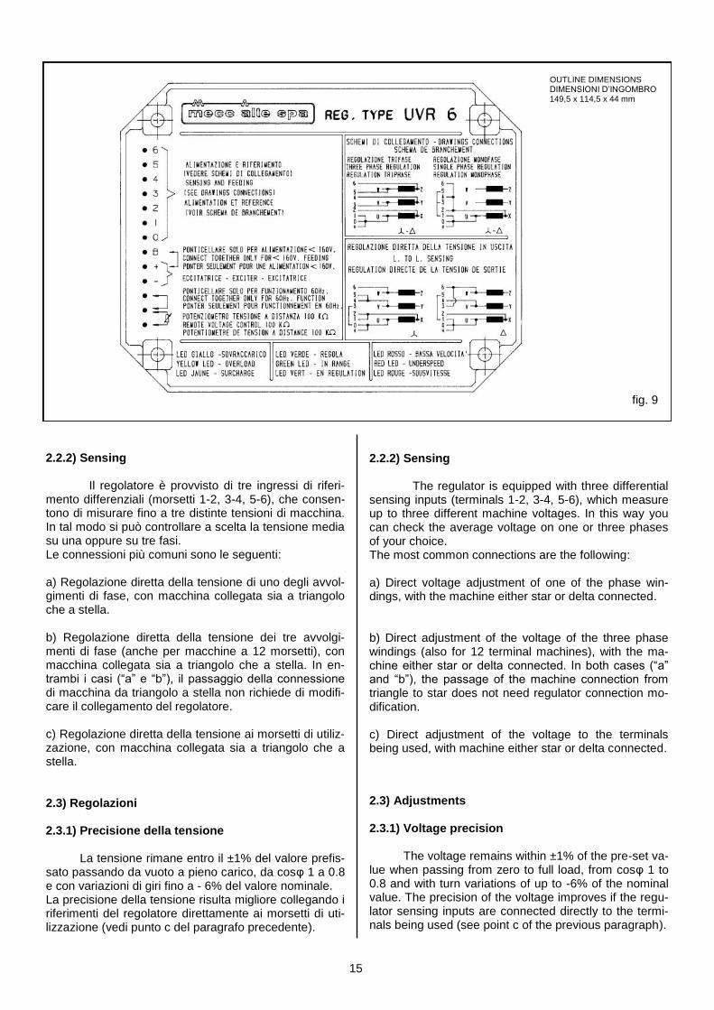
La morsettiera é corredata di indicazioni per facilitarne il collegamento ed evitare errori. Sul retro del regolatore sono mostrati alcuni schemi di collegamento adatti alle diverse condizioni di impiego e corrispondenti a differenti esigenze (vedi fig. 9). 2.2) Caratteristiche tecniche
2.2.1) Alimentazione L'alimentazione al regolatore può essere compresa tra 170 e 270 Vac tra i morsetti + e 2 della morsettiera, con + e B aperti, o tra 80 e 160 Vac sempre tra i mor-setti + e 2, ma con i morsetti + e B connessi assieme. Essa può anche essere distinta dal riferimento e in tale caso deve essere isolata da questo ultimo.
fig. 8
2) U.V.R.6 AND U.V.R.6-H400 ELECTRONIC REGULATOR 2.1) General characteristics The regulators of the series UVR6 are advanced design electronic regulators that ensure excellent per-formances of the alternators while running and during starting. They are equipped with a complete protection system against operation conditions that could be dangerous for the machine. Hereafter with the wording UVR6 we mean all the regulators suitable for being used at 50Hz and 60Hz, both threephase and singlephase, with the wording UVR6-H400 we mean all the regulators suitable for being used at 400Hz. The components of these regulators (see fig. 8) are mo-dern, utilising solid-state integrated circuit technology. These components were chosen to guarantee maxi-mum durability and reliability. The entire unit, also made using a hybrid circuit, is inside a box of modest dimen-sions that has been impregnated with resin to protect against vibrations and ingress of water..
The terminal board is equipped with indications to help connection and avoid errors. Some connection diagrams that are suitable for different configurations are given on the back of the regulator (see fig. 9). 2.2) Technical characteristics
2.2.1) Supply The supply to the regulator can be from 170 to 270 Vac between terminals + and 2 of the terminal board, with + and B not connected, or from 80 to 160 Vac between terminals + and 2 but with + and B connected to each other. Supply can also be separate from the sensing and in this case should be insulated from it.
U.V.R.6 - U.V.R.6-H400
15
2.2.2) Sensing Il regolatore è provvisto di tre ingressi di riferi-mento differenziali (morsetti 1-2, 3-4, 5-6), che consen-tono di misurare fino a tre distinte tensioni di macchina. In tal modo si può controllare a scelta la tensione media su una oppure su tre fasi. Le connessioni più comuni sono le seguenti: a) Regolazione diretta della tensione di uno degli avvol-gimenti di fase, con macchina collegata sia a triangolo che a stella. b) Regolazione diretta della tensione dei tre avvolgi-menti di fase (anche per macchine a 12 morsetti), con macchina collegata sia a triangolo che a stella. In en-trambi i casi (“a” e “b”), il passaggio della connessione di macchina da triangolo a stella non richiede di modifi-care il collegamento del regolatore. c) Regolazione diretta della tensione ai morsetti di utiliz-zazione, con macchina collegata sia a triangolo che a stella. 2.3) Regolazioni 2.3.1) Precisione della tensione La tensione rimane entro il ±1% del valore prefis-sato passando da vuoto a pieno carico, da cosφ 1 a 0.8 e con variazioni di giri fino a - 6% del valore nominale. La precisione della tensione risulta migliore collegando i riferimenti del regolatore direttamente ai morsetti di uti-lizzazione (vedi punto c del paragrafo precedente).
fig. 9
2.2.2) Sensing The regulator is equipped with three differential sensing inputs (terminals 1-2, 3-4, 5-6), which measure up to three different machine voltages. In this way you can check the average voltage on one or three phases of your choice. The most common connections are the following: a) Direct voltage adjustment of one of the phase win-dings, with the machine either star or delta connected. b) Direct adjustment of the voltage of the three phase windings (also for 12 terminal machines), with the ma-chine either star or delta connected. In both cases (“a” and “b”), the passage of the machine connection from triangle to star does not need regulator connection mo-dification. c) Direct adjustment of the voltage to the terminals being used, with machine either star or delta connected.
2.3) Adjustments 2.3.1) Voltage precision The voltage remains within ±1% of the pre-set va-lue when passing from zero to full load, from cosφ 1 to 0.8 and with turn variations of up to -6% of the nominal value. The precision of the voltage improves if the regu-lator sensing inputs are connected directly to the termi-nals being used (see point c of the previous paragraph).
OUTLINE DIMENSIONS DIMENSIONI D’INGOMBRO 149,5 x 114,5 x 44 mm
16
2.3.2) Regolazione della tensione La tensione può essere regolata tramite l'apposito potenziometro contrassegnato "VOLT". È possibile ottenere la regolazione della tensione in un range di almeno il ± 5% inserendo un potenziometro da 100KΩ (qualora la tensione di riferimento sia maggiore di 200V) o un potenziometro da 100KΩ con in serie una resistenza da 100KΩ (qualora la tensione di riferimento sia inferiore a 200V), sugli appositi morsetti della mor-settiera contrassegnati con il simbolo di una resistenza variabile. 2.3.3) Regolazione del tempo di risposta in transitorio Il regolatore è dotato di un potenziometro stabilità "STAB" che consente di variare la risposta del regolatore in modo da limitare le pendolazioni e ottenere dalla macchina un minimo tempo di ripristino della tensione al valore nominale, dopo l'applicazione o sgancio di un carico. Ciò consente l'utilizzazione ottimale del regolatore UVR6 su tutta la vasta gamma di alternatori Mecc Alte. 2.4) Protezioni Il regolatore è provvisto di due protezioni, il cui in-tervento è segnalato dall'accensione dei rispettivi led: a) protezione ritardata ai sovraccarichi (led giallo). b) protezione di bassa velocità (led rosso). Entrambe le protezioni hanno la soglia di inter-vento regolabile tramite i rispettivi potenziometri e pro-vocano una adeguata diminuzione della tensione di macchina che salvaguarda gli avvolgimenti di eccitazio-ne della macchina stessa, impedendone il surriscalda-mento. La protezione di sovraccarico ha un ritardo che consente il sovraccarico momentaneo della macchina per lo spunto di motori elettrici o di altre esigenze. Il regolatore ha anche un terzo led (verde) che acceso indica il corretto funzionamento del regolatore. Tutte queste segnalazioni possono essere visualizzate a di-stanza tramite il "SEGNALATORE PROTEZIONI A DI-STANZA" tipo S.P.D. 96/A disponibile a richiesta (vedere paragrafo 3). Fusibile Il regolatore elettronico UVR6 é dotato di un fusi-bile che protegge l'alternatore da sovrariscaldamenti in caso di malfunzionamento del regolatore stesso; la so-stituzione può essere eseguita con facilità ma si racco-manda che il nuovo fusibile abbia le stesse caratteristi-che di quello da sostituire (250V - 6.3A, rapido tipo F). 2.5) Campo di utilizzazione L'UVR6 può essere utilizzato su tutte le tensioni che vanno da 80 a 480 Vac a 50 Hz. Può anche funzionare a 60 Hz inserendo un ponticello sui morsetti "60 Hz" della morsettiera del regolatore. L’UVR6-H400 può essere utilizzato su tutte le tensioni che vanno da 80 a 480 Vac a 400Hz. Il campo di taratura ammissibile corrisponde a quello specificato per gli alternatori Mecc Alte. 2.6) Autoeccitazione Il regolatore è provvisto di un dispositivo "starter" che sfrutta la tensione residua della macchina per la propria alimentazione e la regolazione dell'eccitazione. Ciò permette l'eccitazione sicura dell'alternatore anche con tensioni residue molto basse ed in tempi molto bre-vi, evitando pendolazioni della tensione nella fase di av-viamento. In questo modo, la tensione si porta al valore nominale stabilizzato, all'incirca nello stesso momento in cui la velocità raggiunge il valore nominale, anche con motori di trascinamento capaci di rampe di avvia-mento molto veloci.
2.3.2) Voltage adjustment
The voltage can be adjusted using the potentio-meter marked "VOLT". It is possible to get a remote voltage regulation in a ran-ge of at least of ± 5% inserting a 100KΩ potentiometer (if the reference voltage is higher than 200V) or a 100KΩ potentiometer with a 100KΩ resistance in series (if the reference voltage is lower than 200V), onto the relevant terminals of the terminal board that are marked a variable resistance symbol.
2.3.3) Transitory reply time adjustment
The regulator is equipped with a “STAB” stability potentiometer with which it is possible to vary the regu-lator reply in a way that limits the swing and obtains from the machine a minimum voltage reset time at no-minal value, after the application or release of a load. This permits optimum use of the UVR6 regulator for the whole range of Mecc Alte alternators.
2.4) Protections
The regulator is equipped with two protection sy-stems, and when they intervene the following LEDs light up: a) Delayed protection for overloads (yellow LED). b) Low speed protection (red LED). Both protections have an intervention threshold that can be adjusted using the respective potentiome-ters. The protections cause an output voltage decrease that reduces the excitation current of the machine, so reducing overheating of the exciter rotor. The overload protection has a delay that let’s the machine overload briefly, for electric motor starting or other needs. The regulator also has a third LED (green) which when lit indicates that the regulator is working correctly. All these signals can be observed remotely using the S.P.D.96/A type “REMOTE PROTECTION SIGNAL-LER” that is available upon request (see paragraph 3). Fuse The UVR6 electronic regulator is equipped with a fuse, which protects the alternator from overheating in cases of regulator malfunction. The fuse can be repla-ced easily, but the new one must have the same cha-racteristics as the one being replaced (250V - 6.3A, quick acting, F type).
2.5) Usage field The UVR6 can be used with all voltages from 80 to 480 Vac at 50 Hz. It can also function at 60 Hz by bridging the "60 Hz" ter-minals of the regulator terminal board. The UVR6-H400 can be used with all voltages from 80 to 480 Vac at 400 Hz. The admissible calibration field corresponds to the one specified for Mecc Alte alternators.
2.6) Self-excitation The regulator is equipped with a “starter” device that utilises the residual voltage of the machine for sup-ply and excitation adjustment. This permits safe alterna-tor excitation, also with very low residual voltages and in very short time, avoiding voltage swings during the star-ting phase. In this way, the voltage rises to the stabili-sed nominal value, approximately at the same moment when the speed reaches nominal value, even with prime movers with very fast starting ramps.
17
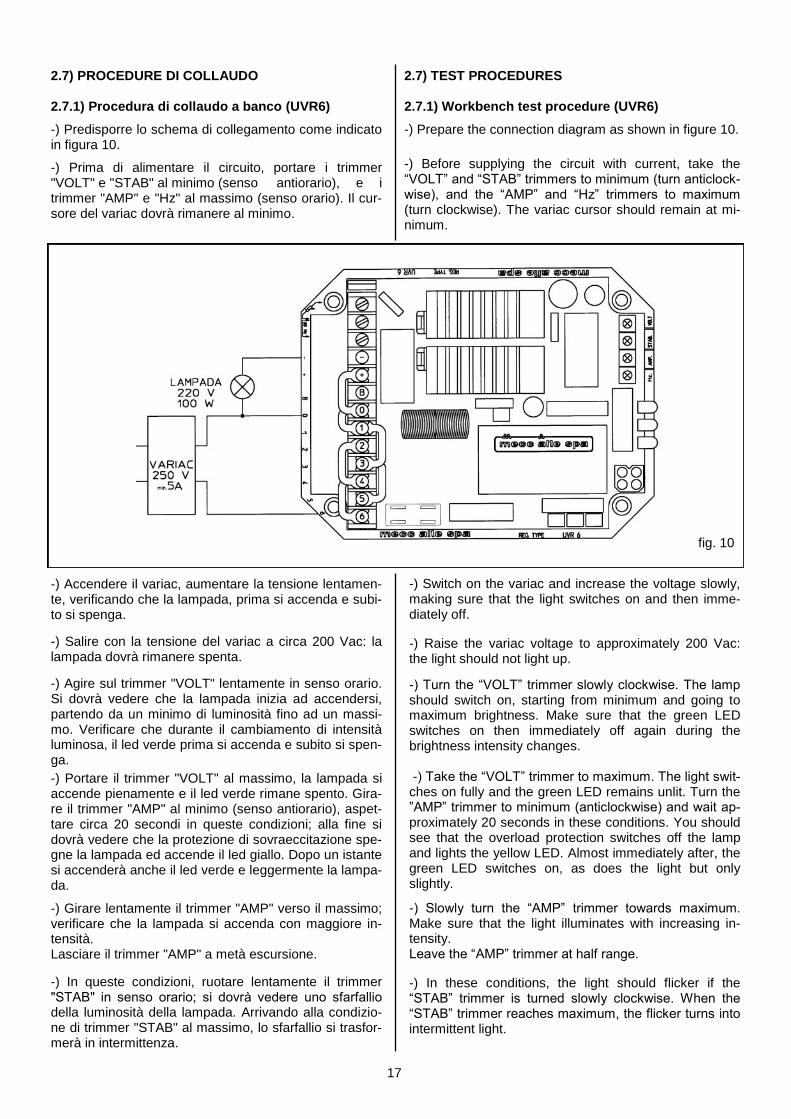
2.7) PROCEDURE DI COLLAUDO 2.7.1) Procedura di collaudo a banco (UVR6) -) Predisporre lo schema di collegamento come indicato in figura 10. -) Prima di alimentare il circuito, portare i trimmer "VOLT" e "STAB" al minimo (senso antiorario), e i trimmer "AMP" e "Hz" al massimo (senso orario). Il cur-sore del variac dovrà rimanere al minimo.
-) Accendere il variac, aumentare la tensione lentamen-te, verificando che la lampada, prima si accenda e subi-to si spenga. -) Salire con la tensione del variac a circa 200 Vac: la lampada dovrà rimanere spenta. -) Agire sul trimmer "VOLT" lentamente in senso orario. Si dovrà vedere che la lampada inizia ad accendersi, partendo da un minimo di luminosità fino ad un massi-mo. Verificare che durante il cambiamento di intensità luminosa, il led verde prima si accenda e subito si spen-ga.
-) Portare il trimmer "VOLT" al massimo, la lampada si accende pienamente e il led verde rimane spento. Gira-re il trimmer "AMP" al minimo (senso antiorario), aspet-tare circa 20 secondi in queste condizioni; alla fine si dovrà vedere che la protezione di sovraeccitazione spe-gne la lampada ed accende il led giallo. Dopo un istante si accenderà anche il led verde e leggermente la lampa-da.
-) Girare lentamente il trimmer "AMP" verso il massimo; verificare che la lampada si accenda con maggiore in-tensità. Lasciare il trimmer "AMP" a metà escursione.
-) In queste condizioni, ruotare lentamente il trimmer "STAB" in senso orario; si dovrà vedere uno sfarfallio della luminosità della lampada. Arrivando alla condizio-ne di trimmer "STAB" al massimo, lo sfarfallio si trasfor-merà in intermittenza.
fig. 10
2.7) TEST PROCEDURES 2.7.1) Workbench test procedure (UVR6) -) Prepare the connection diagram as shown in figure 10.
-) Before supplying the circuit with current, take the “VOLT” and “STAB” trimmers to minimum (turn anticlock-wise), and the “AMP” and “Hz” trimmers to maximum (turn clockwise). The variac cursor should remain at mi-nimum.
-) Switch on the variac and increase the voltage slowly, making sure that the light switches on and then imme-diately off.
-) Raise the variac voltage to approximately 200 Vac: the light should not light up.
-) Turn the “VOLT” trimmer slowly clockwise. The lamp should switch on, starting from minimum and going to maximum brightness. Make sure that the green LED switches on then immediately off again during the brightness intensity changes. -) Take the “VOLT” trimmer to maximum. The light swit-ches on fully and the green LED remains unlit. Turn the ”AMP” trimmer to minimum (anticlockwise) and wait ap-proximately 20 seconds in these conditions. You should see that the overload protection switches off the lamp and lights the yellow LED. Almost immediately after, the green LED switches on, as does the light but only slightly.
-) Slowly turn the “AMP” trimmer towards maximum. Make sure that the light illuminates with increasing in-tensity. Leave the “AMP” trimmer at half range.
-) In these conditions, the light should flicker if the “STAB” trimmer is turned slowly clockwise. When the “STAB” trimmer reaches maximum, the flicker turns into intermittent light.

18
-) Riportare il trimmer "STAB" al minimo. In queste con-dizioni i led verde e giallo sono accesi, e la lampada è in uno stato di luminosità media. -) Girare il trimmer "Hz" al minimo (senso antiorario), ve-rificare che il led rosso si accenda. NOTA: Se il banco di prova fosse a 50 Hz, ed il led ros-so non si accendesse, facendo un ponticello sui termi-nali della morsettiera indicata come "Hz", il led rosso deve accendersi. Se il banco di prova fosse a 60 Hz, la non accensione del led rosso non dovrà considerarsi come un problema del regolatore. In questo caso la pro-tezione di bassa frequenza deve essere provata in mac-china. -) Cortocircuitare i terminali del potenziometro a distan-za: si dovrà vedere che la lampada si accende con maggiore intensità. Se, in tutte le prove sopracitate si riscontrano i compor-tamenti descritti, il regolatore in esame puo' considerarsi idoneo al funzionamento. 2.7.2) Procedura di collaudo su macchina (UVR6 e UVR6-H400) Il regolatore dovra' essere collegato in conformita' allo schema relativo alla figura 11.
-) Prima di avviare il sistema, ruotare i trimmer "VOLT" e "STAB" completamente in senso antiorario, ed i trimmer "AMP" e "Hz” completamente in senso orario. -) Collegare una lampada tra fase e neutro del genera-tore (scegliere la tensione di lavoro della lampada in re-lazione al valore nominale della tensione fase-neutro del generatore).
-) Take the “STAB” trimmer back to minimum. The green and yellow LEDs should be lit, and the light should be at medium brightness.
-) Turn the “Hz” trimmer to minimum (anticlockwise). Make sure that the red LED switches on. NOTE: If the test bench is at 50 Hz and the red LED does not illuminate, bridge the “Hz” terminals of the ter-minal board. If the test bench is at 60 Hz and the red LED does not light up, this does not mean that the regu-lator has problems. The low frequency protection should, instead, be tested in the machine.
-) Short-circuit the remote potentiometer terminals. The light should switch on with greater intensity. If during all the above tests the described behaviour happens, the regulator being examined is suitable for operation. 2.7.2) Machine test procedure (UVR6 and UVR6-H400) The regulator should be connected as shown in the relevant diagram in figure 11.
-) Before starting the system, turn the "VOLT" and "STAB" trimmers fully anticlockwise and the "AMP" and "Hz” trimmers fully clockwise. -) Connect a light between the generator phase and neutral (select the working voltage of the light in relation to the nominal value of the generator phase-neutral vol-tage).
fig. 11
19
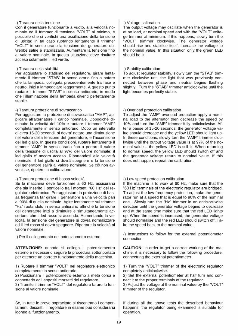
-) Taratura della tensione Con il generatore funzionante a vuoto, alla velocità no-minale ed il trimmer di tensione "VOLT” al minimo, é possibile che si verifichi una oscillazione della tensione di uscita; in tal caso ruotando lentamente il trimmer "VOLT" in senso orario la tensione del generatore do-vrebbe salire e stabilizzarsi. Aumentare la tensione fino al valore nominale. In questa situazione deve risultare acceso solamente il led verde. -) Taratura della stabilità Per aggiustare lo statismo del regolatore, girare lenta-mente il trimmer “STAB” in senso orario fino a notare che la lampada, collegata precedentemente tra fase e neutro, inizi a lampeggiare leggermente. A questo punto ruotare il trimmer "STAB" in senso antiorario, in modo che I'illuminazione della lampada diventi perfettamente stabile. -) Taratura protezione di sovraccarico Per aggiustare la protezione di sovraccarico "AMP", ap-plicare all'alternatore il carico nominale. Dopodichè di-minuire la velocità del 10% e ruotare il trimmer "AMP" completamente in senso antiorario. Dopo un intervallo di circa 15-20 secondi, si dovra' notare una diminuzione nel valore della tensione del generatore, e l'accensione del led giallo. In queste condizioni, ruotare lentamente il trimmer "AMP" in senso orario fino a portare il valore della tensione di uscita al 97% del valore nominale: il led giallo e' ancora acceso. Riportandosi alla velocità nominale, il led giallo si dovrà spegnere e la tensione del generatore salirà al valore nominale. Se ciò non av-venisse, ripetere la calibrazione. -) Taratura protezione di bassa velocità Se la macchina deve funzionare a 60 Hz, assicurarsi che sia inserito il ponticello tra i morsetti "60 Hz" del re-golatore elettronico. Per aggiustare la protezione di bas-sa frequenza far girare il generatore a una velocità pari al 90% di quella nominale. Agire lentamente sul trimmer "Hz” ruotandolo in senso antiorario affinchè la tensione del generatore inizi a diminuire e simultaneamente ac-certarsi che il led rosso si accenda. Aumentando la ve-locità, la tensione del generatore si dovrà normalizzare ed il led rosso si dovrà spegnere. Riportare la velocità al valore nominale.
-) Per il collegamento del potenziometro esterno:
ATTENZIONE: quando si collega il potenziomentro esterno è necessario seguire la procedura sottoriportata per ottenere un corretto funzionamento della macchina. 1) Ruotare il trimmer “VOLT” nel regolatore elettronico completamente in senso antiorario. 2) Posizionare il potenziometro esterno a metà corsa e connetterlo agli appositi morsetti del regolatore. 3) Tramite il trimmer “VOLT” del regolatore tarare la ten-sione al valore nominale. Se, in tutte le prove sopracitate si riscontrano i compor-tamenti descritti, il regolatore in esame può considerarsi idoneo al funzionamento.
-) Voltage calibration The output voltage may oscillate when the generator is at no load, at nominal speed and with the “VOLT” volta-ge trimmer at minimum. If this happens, slowly turn the “VOLT” trimmer clockwise. The generator voltage should rise and stabilise itself. Increase the voltage to the nominal value. In this situation only the green LED should be lit. -) Stability calibration To adjust regulator stability, slowly turn the “STAB” trim-mer clockwise until the light that was previously con-nected between phase and neutral begins flashing slightly. Turn the “STAB” trimmer anticlockwise until the light becomes perfectly stable. -) Overload protection calibration To adjust the “AMP” overload protection apply a nomi-nal load to the alternator then decrease the speed by 10% and turn the “AMP” trimmer fully anticlockwise. Af-ter a pause of 15-20 seconds, the generator voltage va-lue should decrease and the yellow LED should light up. In these conditions, slowly turn the “AMP” trimmer cloc-kwise until the output voltage value is at 97% of the no-minal value – the yellow LED is still lit. When returning to normal speed, the yellow LED should switch off and the generator voltage return to nominal value. If this does not happen, repeat the calibration. -) Low speed protection calibration If the machine is to work at 60 Hz, make sure that the “60 Hz” terminals of the electronic regulator are bridged. To adjust the low frequency protection, make the gene-rator run at a speed that is equal to 90% of the nominal one. Slowly turn the “Hz” trimmer in an anticlockwise direction until the generator voltage begins to decrease and at the same time make sure that the red LED lights up. When the speed is increased, the generator voltage should normalise and the red LED should switch off. Ta-ke the speed back to the nominal value. -) Instructions to follow for the external potentiometer connection: CAUTION: in order to get a correct working of the ma-chine, it is necessary to follow the following procedure, connectring the external potentiometer. 1) Turn the “VOLT” trimmer of the electronic regulator completely anticlockwise. 2) Set the external potentiometer at half turn and con-nect it to the proper terminals of the regulator. 3) Adjust the voltage at the nominal value by the “VOLT” trimmer of the regulator. If during all the above tests the described behaviour happens, the regulator being examined is suitable for operation.
20
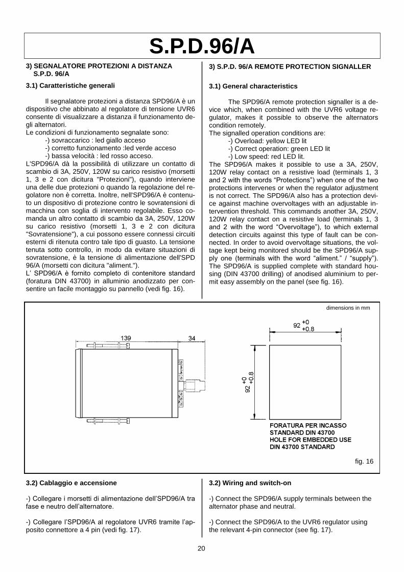
3) SEGNALATORE PROTEZIONI A DISTANZA S.P.D. 96/A 3.1) Caratteristiche generali Il segnalatore protezioni a distanza SPD96/A è un dispositivo che abbinato al regolatore di tensione UVR6 consente di visualizzare a distanza il funzionamento de-gli alternatori. Le condizioni di funzionamento segnalate sono: -) sovraccarico : led giallo acceso -) corretto funzionamento :led verde acceso -) bassa velocità : led rosso acceso. L'SPD96/A dà la possibilità di utilizzare un contatto di scambio di 3A, 250V, 120W su carico resistivo (morsetti 1, 3 e 2 con dicitura "Protezioni"), quando interviene una delle due protezioni o quando la regolazione del re-golatore non è corretta. Inoltre, nell'SPD96/A è contenu-to un dispositivo di protezione contro le sovratensioni di macchina con soglia di intervento regolabile. Esso co-manda un altro contatto di scambio da 3A, 250V, 120W su carico resistivo (morsetti 1, 3 e 2 con dicitura "Sovratensione"), a cui possono essere connessi circuiti esterni di ritenuta contro tale tipo di guasto. La tensione tenuta sotto controllo, in modo da evitare situazioni di sovratensione, è la tensione di alimentazione dell'SPD 96/A (morsetti con dicitura "aliment."). L’ SPD96/A è fornito completo di contenitore standard (foratura DIN 43700) in alluminio anodizzato per con-sentire un facile montaggio su pannello (vedi fig. 16).
3.2) Cablaggio e accensione -) Collegare i morsetti di alimentazione dell’SPD96/A tra fase e neutro dell’alternatore. -) Collegare l’SPD96/A al regolatore UVR6 tramite l’ap-posito connettore a 4 pin (vedi fig. 17).
fig. 16
dimensions in mm
3) S.P.D. 96/A REMOTE PROTECTION SIGNALLER 3.1) General characteristics The SPD96/A remote protection signaller is a de-vice which, when combined with the UVR6 voltage re-gulator, makes it possible to observe the alternators condition remotely. The signalled operation conditions are: -) Overload: yellow LED lit -) Correct operation: green LED lit -) Low speed: red LED lit. The SPD96/A makes it possible to use a 3A, 250V, 120W relay contact on a resistive load (terminals 1, 3 and 2 with the words “Protections”) when one of the two protections intervenes or when the regulator adjustment is not correct. The SPD96/A also has a protection devi-ce against machine overvoltages with an adjustable in-tervention threshold. This commands another 3A, 250V, 120W relay contact on a resistive load (terminals 1, 3 and 2 with the word “Overvoltage”), to which external detection circuits against this type of fault can be con-nected. In order to avoid overvoltage situations, the vol-tage kept being monitored should be the SPD96/A sup-ply one (terminals with the word “aliment.” / “supply”). The SPD96/A is supplied complete with standard hou-sing (DIN 43700 drilling) of anodised aluminium to per-mit easy assembly on the panel (see fig. 16).
3.2) Wiring and switch-on -) Connect the SPD96/A supply terminals between the alternator phase and neutral. -) Connect the SPD96/A to the UVR6 regulator using the relevant 4-pin connector (see fig. 17).
S.P.D.96/A

21
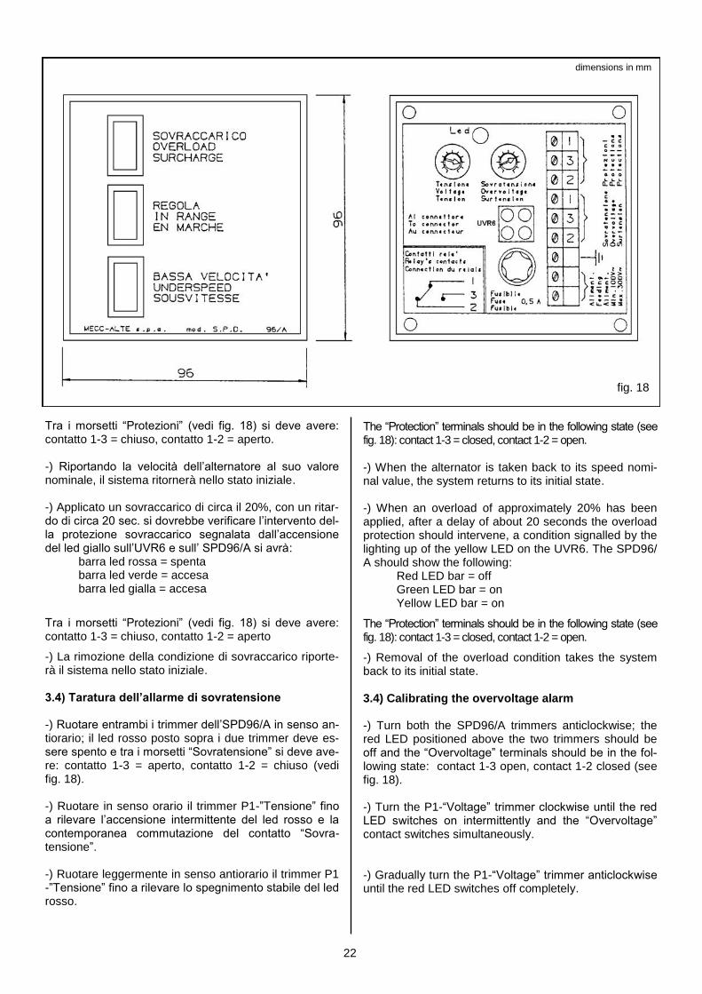
-) Portare l’alternatore alla sua velocità nominale: l’SPD96/A e l’UVR6 sono ora alimentati; con l’alternato-re a vuoto, se tutto è stato cablato correttamente e se il regolatore UVR6 è già stato tarato, sui morsetti di stato-re si misura la tensione nominale dell’alternatore ed i led dell’UVR6 si presentano nel seguente stato: led rosso = spento led verde = acceso led giallo = spento. -) Lo stato delle barre led dell’SPD96/A deve rispecchia-re esattamente quello dei led dell’UVR6. -) Tra i morsetti “Protezioni” (vedi fig. 18) si deve avere: contatto 1-3 = aperto, contatto 1-2 = chiuso. 3.3) Intervento delle protezioni dell’ UVR6 -) Diminuire la velocità dell’alternatore fino all’intervento della protezione bassa velocità segnalata dall’accensio-ne del led rosso sull’UVR6 e sull’ SPD96/A si avrà: barra led rossa = accesa barra led verde = accesa barra led gialla = spenta
fig. 17
-) Take the alternator to nominal speed: the SPD96/A and the UVR6 are now supplied with current. With the alternator unloaded, if everything has been connected correctly and if the UVR6 regulator has already been calibrated, the nominal voltage of the alternator can be measured and the UVR6 LED’s are in the following state: Red LED = off Green LED = on Yellow LED = off. -) The SPD96/A bars must exactly mirror those of the UVR6 LED’s. -) The “Protection” terminals should be in the following state (see fig. 18): contact 1-3 = open, contact 1-2 = closed. 3.3) UVR6 protection intervention -) Decrease the alternator speed until the low speed protection intervenes, which is signalled when the red LED on the UVR6 lights up. The following situation is on the SPD96/A: Red LED bar = on Green LED bar = on Yellow LED bar = off
22
Tra i morsetti “Protezioni” (vedi fig. 18) si deve avere: contatto 1-3 = chiuso, contatto 1-2 = aperto. -) Riportando la velocità dell’alternatore al suo valore nominale, il sistema ritornerà nello stato iniziale. -) Applicato un sovraccarico di circa il 20%, con un ritar-do di circa 20 sec. si dovrebbe verificare l’intervento del-la protezione sovraccarico segnalata dall’accensione del led giallo sull’UVR6 e sull’ SPD96/A si avrà: barra led rossa = spenta barra led verde = accesa barra led gialla = accesa Tra i morsetti “Protezioni” (vedi fig. 18) si deve avere: contatto 1-3 = chiuso, contatto 1-2 = aperto -) La rimozione della condizione di sovraccarico riporte-rà il sistema nello stato iniziale. 3.4) Taratura dell’allarme di sovratensione -) Ruotare entrambi i trimmer dell’SPD96/A in senso an-tiorario; il led rosso posto sopra i due trimmer deve es-sere spento e tra i morsetti “Sovratensione” si deve ave-re: contatto 1-3 = aperto, contatto 1-2 = chiuso (vedi fig. 18). -) Ruotare in senso orario il trimmer P1-”Tensione” fino a rilevare l’accensione intermittente del led rosso e la contemporanea commutazione del contatto “Sovra-tensione”. -) Ruotare leggermente in senso antiorario il trimmer P1-”Tensione” fino a rilevare lo spegnimento stabile del led rosso.
fig. 18
dimensions in mm
The “Protection” terminals should be in the following state (see fig. 18): contact 1-3 = closed, contact 1-2 = open. -) When the alternator is taken back to its speed nomi-nal value, the system returns to its initial state. -) When an overload of approximately 20% has been applied, after a delay of about 20 seconds the overload protection should intervene, a condition signalled by the lighting up of the yellow LED on the UVR6. The SPD96/A should show the following: Red LED bar = off Green LED bar = on Yellow LED bar = on The “Protection” terminals should be in the following state (see fig. 18): contact 1-3 = closed, contact 1-2 = open. -) Removal of the overload condition takes the system back to its initial state. 3.4) Calibrating the overvoltage alarm -) Turn both the SPD96/A trimmers anticlockwise; the red LED positioned above the two trimmers should be off and the “Overvoltage” terminals should be in the fol-lowing state: contact 1-3 open, contact 1-2 closed (see fig. 18). -) Turn the P1-“Voltage” trimmer clockwise until the red LED switches on intermittently and the “Overvoltage” contact switches simultaneously. -) Gradually turn the P1-“Voltage” trimmer anticlockwise until the red LED switches off completely.
23
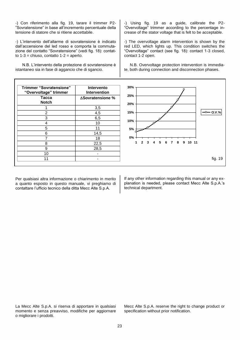
-) Con riferimento alla fig. 19, tarare il trimmer P2-”Sovratensione” in base all’incremento percentuale della tensione di statore che si ritiene accettabile. -) L’intervento dell’allarme di sovratensione è indicato dall’accensione del led rosso e comporta la commuta-zione del contatto “Sovratensione” (vedi fig. 18): contat-to 1-3 = chiuso, contatto 1-2 = aperto.
N.B. L’intervento della protezione di sovratensione è
istantaneo sia in fase di aggancio che di sgancio.
Trimmer “Sovratensione” “Overvoltage” trimmer
Intervento Intervention
Tacca Notch
Sovratensione %
1 3,5
2 4,5
3 6,5
4 10
5 11
6 14,5
7 18
8 22,5
9 28,5
10 -
11 -
0%
5%
10%
15%
20%
25%
30%
1 2 3 4 5 6 7 8 9 10 11
O.V.%
fig. 19
Per qualsiasi altra informazione o chiarimento in merito a quanto esposto in questo manuale, vi preghiamo di contattare l’ufficio tecnico della ditta Mecc Alte S.p.A.
-) Using fig. 19 as a guide, calibrate the P2-“Overvoltage” trimmer according to the percentage in-crease of the stator voltage that is felt to be acceptable. -) The overvoltage alarm intervention is shown by the red LED, which lights up. This condition switches the “Overvoltage” contact (see fig. 18): contact 1-3 closed, contact 1-2 open.
N.B. Overvoltage protection intervention is immedia-te, both during connection and disconnection phases.
If any other information regarding this manual or any ex-planation is needed, please contact Mecc Alte S.p.A.’s technical department.
La Mecc Alte S.p.A. si riserva di apportare in qualsiasi momento e senza preavviso, modifiche per aggiornare o migliorare i prodotti.
Mecc Alte S.p.A. reserve the right to change product or specification without prior notification.

Mecc Alte SpAVia Roma 20 – 36051 Creazzo Vicenza – ITALYT: +39 0444 396111F: +39 0444 396166E: [email protected] [email protected]
United KingdomMecc Alte U.K. LTD 6 Lands’ End Way Oakham RutlandT: +44 (0) 1572 771160F: +44 (0) 1572 771161E: [email protected] [email protected]
FranceMecc Alte International S.A. Z.E.La Gagnerie 16330 ST.Amant De BoixeT: +33 (0) 545 397562F: +33 (0) 545 398820E: [email protected] [email protected]
SpainMecc Alte España S.A. C/ Rio Taibilla, 2 Polig. Ind. Los Valeros 03178 Benijofar (Alicante)T: +34 (0) 96 6702152F: +34 (0) 96 6700103E: [email protected] [email protected]
GermanyMecc Alte Generatoren GmbH Ensener Weg 21 D-51149 KölnT: +49 (0) 2203 503810F: +49 (0) 2203 503796E: [email protected] [email protected]
Far EastMecc Alte (F.E.) PTE LTD 19 Kian Teck Drive Singapore 628836 T: +65 62 657122 F: +65 62 653991 E: [email protected] [email protected]
IndiaMecc Alte India PVT LTD Plot NO: 1, Sanaswadi Talegaon Dhamdhere Road Taluka: Shirur, District: Pune - 412208 Maharashtra, IndiaT: +91 2137 619600F: +91 2137 619699E: [email protected] [email protected]
U.S.A. and CanadaMecc Alte Inc. 1229 Adam Drive McHenry, IL, 60051T: +1 815 344 0530F: +1 815 344 0535E: [email protected] [email protected]
ChinaMecc Alte Alternator Haimen LTD 755 Nanhai East Rd Jiangsu HEDZ 226100 PRCT: +86 (0) 513 82325758F: +86 (0)513 82325768E: [email protected] [email protected]
AustraliaMecc Alte Alternators PTY LTD 10 Duncan Road, PO Box 1046 Dry Creek, 5094, South AustraliaT: +61 (0)8 8349 8422F: +61 (0)8 8349 8455E: [email protected] [email protected]
www.meccalte.com