Embed Size (px)
Citation preview
HIGHWAYS DEPARTMENT
GUIDANCE NOTES
ON
DESIGN AND CONSTRUCTION OF
PAVEMENTS WITH PAVING UNITS
Research & Development Division RD/GN/044A
September 2017
RD/GN/044A Guidance Notes on Design
and Construction of Pavements with Paving Units
- i -
TABLE OF CONTENTS
1 INTRODUCTION................................................................................................ 1
2 OBJECTIVE ........................................................................................................ 1
3 TYPES OF PAVING UNITS ............................................................................... 1
3.1 Precast Concrete Materials.......................................................................... 2
3.2 Granite and Artificial Granite Materials ..................................................... 2
3.3 Clay Materials ............................................................................................. 3
3.4 Materials for Special Aesthetic or Memorial Features................................ 3
4 AESTHETICS ...................................................................................................... 4
4.1 Paving Theme ............................................................................................. 4
4.2 Detailed Attributes ...................................................................................... 4
4.2.1 Colours............................................................................................... 4
4.2.2 Sizes ................................................................................................... 4
4.2.3 Laying Patterns .................................................................................. 6
4.2.4 Textures ............................................................................................. 8
4.2.5 Rhythm and Rhyme ......................................................................... 10
4.2.6 Harmony and Coherence ................................................................. 11
5 PAVEMENT STRUCTURE .............................................................................. 11
5.1 Pavement Substructure .............................................................................. 11
5.1.1 Bedding ............................................................................................ 12
5.1.2 Road-base and Sub-base .................................................................. 13
5.1.3 Sub-grade ......................................................................................... 13
5.2 Special Considerations .............................................................................. 13
5.2.1 Carriageways and Run-in ................................................................ 13
5.2.2 Joint Stabilizing Sealers ................................................................... 14
6 GOOD PRACTICE FOR LAYING PAVING UNITS .................................... 14
6.1 Cutting and Trimming ............................................................................... 14
6.2 Edge Restraints ......................................................................................... 16
6.2.1 Kerbs, Channels and Building Lines ............................................... 17
6.2.2 Manholes and Utility Pits ................................................................ 20
6.2.3 Posts and Columns........................................................................... 21
6.2.4 Tree Pits ........................................................................................... 22
6.2.5 Irregular Obstructions ...................................................................... 25
6.2.6 Interfaces with Other Paving Materials / Laying Patterns ............... 25
RD/GN/044A Guidance Notes on Design
and Construction of Pavements with Paving Units
- ii -
TABLE OF CONTENTS (CONT'D)
7 APPLICATIONS AND LIMITATIONS .......................................................... 25
7.1 Applications .............................................................................................. 26
7.1.1 Aesthetics......................................................................................... 26
7.1.2 Ongoing Settlement or Uneven Ground Displacement ................... 26
7.1.3 Frequent Disturbance by Utilities .................................................... 26
7.1.4 Poor Accessibility of Conventional Construction Plants ................. 27
7.2 Limitations ................................................................................................ 27
7.2.1 Footways with Vulnerable Site Conditions ..................................... 27
7.2.2 Carriageways ................................................................................... 28
7.2.3 Industrial Areas ................................................................................ 28
8 GUIDELINES TO AUTHORIZED PERSONS .............................................. 29
PLATES
Plate 4.1 – Using colours of paving units to create interest and enhance local characters of
the environment .............................................................................................. 5
Plate 4.2 – Using smaller-sized paving units on narrow footway to give better scale..... 5
Plate 4.3 – Using larger-sized paving units on wide footway .......................................... 6
Plate 4.4 – Using rectilinear laying pattern to align with straight kerbside ..................... 6
Plate 4.5 – Using transverse paving bands as transitional zones for aligning the direction
of a laying pattern with the curvature of a footway to provide visual continuity
........................................................................................................................ 7
Plate 4.6 – Avoid using laying patterns with abrupt changes in direction ....................... 7
Plate 4.7 – Using an elaborate laying pattern design ....................................................... 8
Plate 4.8 – Using a simple laying pattern design ............................................................. 8
Plate 4.9 – Using a combination of different textures on a wide pavement to provide
contrast and interest........................................................................................ 9
Plate 4.10 – Using a simple texture and uniform laying patterns along a localized strip of
pavement ........................................................................................................ 9
Plate 4.11 – Using repetitive laying patterns tempered with change of colours to create
rhythm and rhyme ........................................................................................ 10
Plate 4.12 – Using repetitive laying in-fill patterns tempered with variation on their sizes
to create rhythm and rhyme.......................................................................... 10
Plate 4.13 – Laying patterns and colours should be designed to harmonize and be
coherent with local characters and the environment .....................................11
RD/GN/044A Guidance Notes on Design
and Construction of Pavements with Paving Units
- iii -
FIGURES
Figure 6.1 – Sizes of paving units to be cut to suit different laying patterns ................. 15
Figure 6.2 – Maximum allowable joint widths between cutting faces and adjoining
paving units / edges ...................................................................................... 16
Figure 6.3 – Typical laying patterns for edge restraints ................................................. 16
Figure 6.4 – Treatment to paving units against kerb edges for 90o herringbone bond
laying pattern ................................................................................................ 17
Figure 6.5 – Treatment to paving units against kerb edges for 45o herringbone bond
laying pattern ................................................................................................ 18
Figure 6.6 – Treatment to paving units against kerb edges for stretcher bond laying
pattern ........................................................................................................... 18
Figure 6.7 – Treatment to paving units against kerb edges for basket-weave bond laying
pattern ........................................................................................................... 19
Figure 6.8 – Treatment to paving units for kerb edges with curved alignment ............. 19
Figure 6.9 – Treatment to paving units adjoining channel edges .................................. 20
Figure 6.10 – Treatment to paving units on or against manhole covers ........................ 21
Figure 6.11 – Treatment to paving units around posts and columns .............................. 22
Figure 6.12 – Reconstruction of tree pits without size modifications ........................... 23
Figure 6.13 – Reconstruction of tree pits with size modifications ................................ 24
Figure 6.14 – Edge treatment for paving units against other paving materials or laying
patterns ......................................................................................................... 25
APPENDICES
Appendix A – Examples for End Details of Edge Restraints......................................... 30
Appendix B – Particular Specifications Published by the Highways Department ........ 42
RD/GN/044A Guidance Notes on Design
and Construction of Pavements with Paving Units
- 1 -
1 INTRODUCTION
In the early 1980s, over 90% of footways in Hong Kong were constructed using
in-situ concrete. In-situ concrete can offer simple, flexible and cheap construction
for footways with basically satisfactory results attained. However, excessive noise
and construction waste are generated during and after breaking of concrete footways
for trench openings. Considerable time is also required for setting and curing of
concrete for trench reinstatement. Given frequent trench works for utility services
installation and maintenance, a lot of inconvenience and nuisance to the general
public would be created by the footways constructed with in-situ concrete.
To address the above concern, the Highways Department had begun studying laying
paving units on footways since 1982. Trials had been conducted at different
locations, including central business areas and areas where there was a large variety of
street furniture. Findings of the trials were satisfactory, with the paving units
remained in good condition after laying, opening and reinstatement of trench works.
With the positive outcome, the Highways Department promulgated specifications and
standard drawings to promote the use of paving units on footways. Up to now, more
than 30% of footways in Hong Kong have been laid with paving units.
2 OBJECTIVE
This set of Guidance Notes updates and supersedes Road Note 9 – Precast Concrete
Unit Paving System of 2006 edition and Guidelines on Good Practice for Laying Unit
Pavers of 2012 edition, and serves as a guideline on design and construction of
pavement using paving units.
3 TYPES OF PAVING UNITS
Paving units can be made of a variety of materials to meet functional and aesthetic
considerations. Under the requirements on dimensions, strength, skid resistances
and durability etc. as stipulated in the General Specification for Civil Engineering
Works (GS) published by the Civil Engineering and Development Department and the
particular specifications in Appendix B of this set of Guidance Notes, paving units
come with different shapes, sizes, thickness and colours in the market.
RD/GN/044A Guidance Notes on Design
and Construction of Pavements with Paving Units
- 2 -
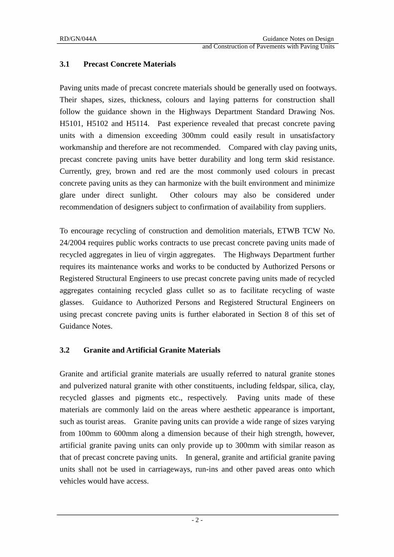
3.1 Precast Concrete Materials
Paving units made of precast concrete materials should be generally used on footways.
Their shapes, sizes, thickness, colours and laying patterns for construction shall
follow the guidance shown in the Highways Department Standard Drawing Nos.
H5101, H5102 and H5114. Past experience revealed that precast concrete paving
units with a dimension exceeding 300mm could easily result in unsatisfactory
workmanship and therefore are not recommended. Compared with clay paving units,
precast concrete paving units have better durability and long term skid resistance.
Currently, grey, brown and red are the most commonly used colours in precast
concrete paving units as they can harmonize with the built environment and minimize
glare under direct sunlight. Other colours may also be considered under
recommendation of designers subject to confirmation of availability from suppliers.
To encourage recycling of construction and demolition materials, ETWB TCW No.
24/2004 requires public works contracts to use precast concrete paving units made of
recycled aggregates in lieu of virgin aggregates. The Highways Department further
requires its maintenance works and works to be conducted by Authorized Persons or
Registered Structural Engineers to use precast concrete paving units made of recycled
aggregates containing recycled glass cullet so as to facilitate recycling of waste
glasses. Guidance to Authorized Persons and Registered Structural Engineers on
using precast concrete paving units is further elaborated in Section 8 of this set of
Guidance Notes.
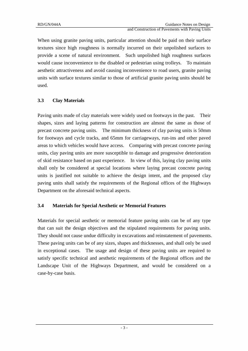
3.2 Granite and Artificial Granite Materials
Granite and artificial granite materials are usually referred to natural granite stones
and pulverized natural granite with other constituents, including feldspar, silica, clay,
recycled glasses and pigments etc., respectively. Paving units made of these
materials are commonly laid on the areas where aesthetic appearance is important,
such as tourist areas. Granite paving units can provide a wide range of sizes varying
from 100mm to 600mm along a dimension because of their high strength, however,
artificial granite paving units can only provide up to 300mm with similar reason as
that of precast concrete paving units. In general, granite and artificial granite paving
units shall not be used in carriageways, run-ins and other paved areas onto which
vehicles would have access.
RD/GN/044A Guidance Notes on Design
and Construction of Pavements with Paving Units
- 3 -
When using granite paving units, particular attention should be paid on their surface
textures since high roughness is normally incurred on their unpolished surfaces to
provide a scene of natural environment. Such unpolished high roughness surfaces
would cause inconvenience to the disabled or pedestrian using trolleys. To maintain
aesthetic attractiveness and avoid causing inconvenience to road users, granite paving
units with surface textures similar to those of artificial granite paving units should be
used.
3.3 Clay Materials
Paving units made of clay materials were widely used on footways in the past. Their
shapes, sizes and laying patterns for construction are almost the same as those of
precast concrete paving units. The minimum thickness of clay paving units is 50mm
for footways and cycle tracks, and 65mm for carriageways, run-ins and other paved
areas to which vehicles would have access. Comparing with precast concrete paving
units, clay paving units are more susceptible to damage and progressive deterioration
of skid resistance based on past experience. In view of this, laying clay paving units
shall only be considered at special locations where laying precast concrete paving
units is justified not suitable to achieve the design intent, and the proposed clay
paving units shall satisfy the requirements of the Regional offices of the Highways
Department on the aforesaid technical aspects.
3.4 Materials for Special Aesthetic or Memorial Features
Materials for special aesthetic or memorial feature paving units can be of any type
that can suit the design objectives and the stipulated requirements for paving units.
They should not cause undue difficulty in excavations and reinstatement of pavements.
These paving units can be of any sizes, shapes and thicknesses, and shall only be used
in exceptional cases. The usage and design of these paving units are required to
satisfy specific technical and aesthetic requirements of the Regional offices and the
Landscape Unit of the Highways Department, and would be considered on a
case-by-case basis.
RD/GN/044A Guidance Notes on Design
and Construction of Pavements with Paving Units
- 4 -
4 AESTHETICS
Aesthetics, including themes of paving and detailed attributes, is one of the
considerations in designing footways for new and maintenance works. Themes of
paving could affect coherence and harmony of footways to the surrounding
environments, which in turn is dictated by detailed attributes, such as laying patterns
and textures, etc. adopted.
4.1 Paving Theme
A theme of paving should be set down for a footway based on its pedestrian flow and
prevailing use of the land where it locates so as to enhance streetscape in that area.
For an area that would attract public’s attention or is designed for recreational purpose,
some preferable paving units such as granite, artificial granite or high quality paving
units may be considered subject to the design justification submitted to the Landscape
Unit of the Highways Department for comment. Under most circumstances, precast
concrete paving units should be considered as the norm. Where appropriate, they
may be laid in combination with other types of paving units as highlight to enhance
their visual appearance.
4.2 Detailed Attributes
The theme of paving should be clearly expressed and defined by using colours, sizes,
laying patterns and textures. Visual rhythm, rhyme, harmony and other
considerations at special areas should also be taken into account in the design stage.
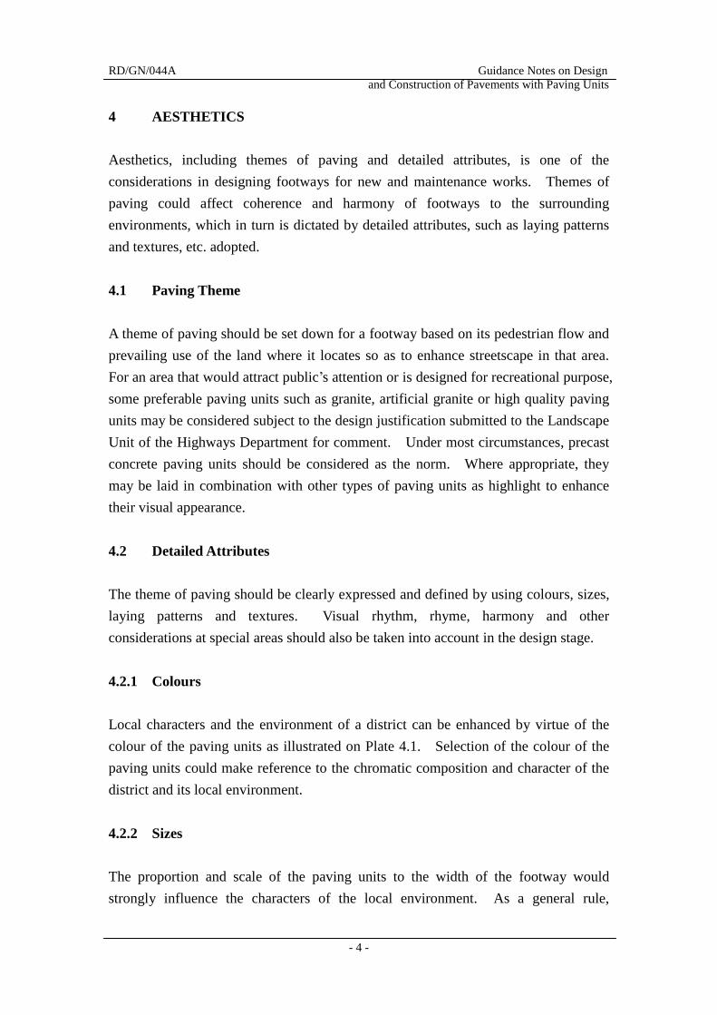
4.2.1 Colours
Local characters and the environment of a district can be enhanced by virtue of the
colour of the paving units as illustrated on Plate 4.1. Selection of the colour of the
paving units could make reference to the chromatic composition and character of the
district and its local environment.
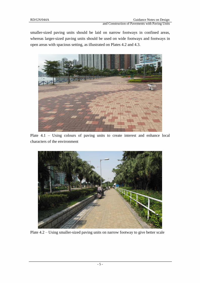
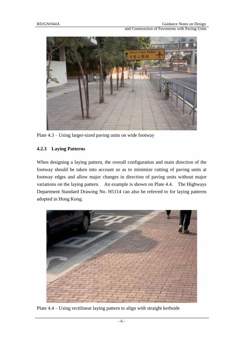
4.2.2 Sizes
The proportion and scale of the paving units to the width of the footway would
strongly influence the characters of the local environment. As a general rule,
RD/GN/044A Guidance Notes on Design
and Construction of Pavements with Paving Units
- 5 -
smaller-sized paving units should be laid on narrow footways in confined areas,
whereas larger-sized paving units should be used on wide footways and footways in
open areas with spacious setting, as illustrated on Plates 4.2 and 4.3.
Plate 4.1 – Using colours of paving units to create interest and enhance local
characters of the environment
Plate 4.2 – Using smaller-sized paving units on narrow footway to give better scale
RD/GN/044A Guidance Notes on Design
and Construction of Pavements with Paving Units
- 6 -
Plate 4.3 – Using larger-sized paving units on wide footway
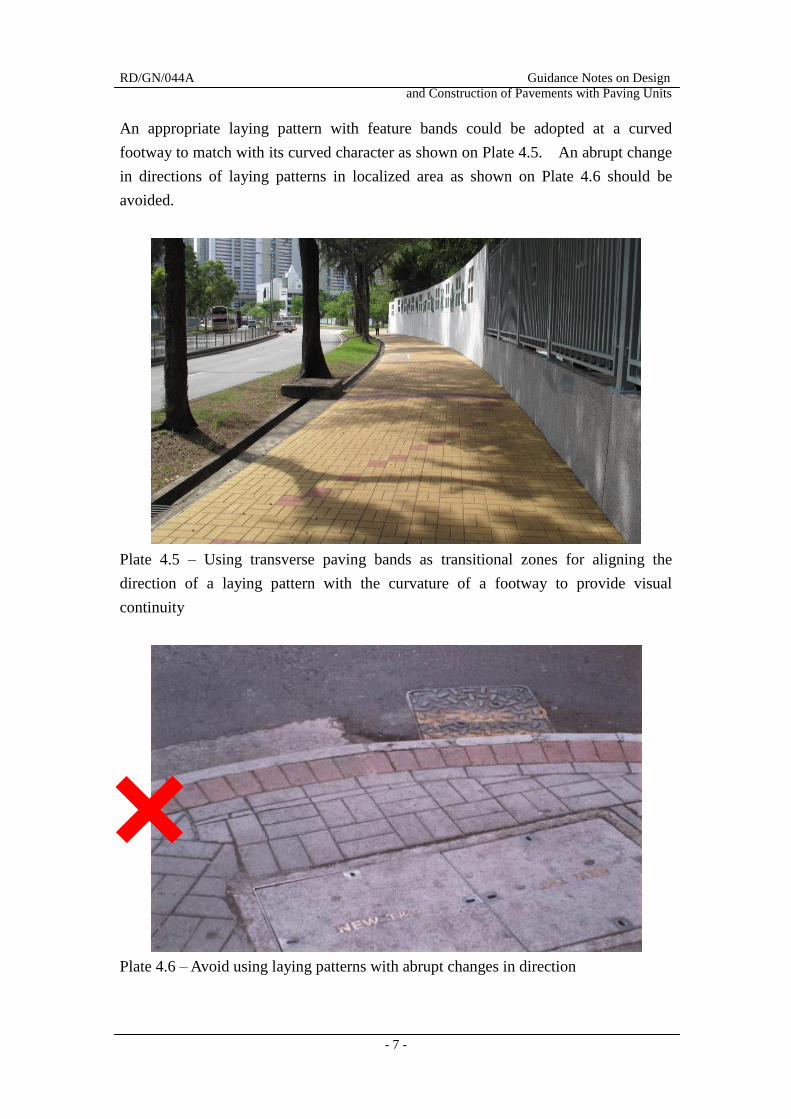
4.2.3 Laying Patterns
When designing a laying pattern, the overall configuration and main direction of the
footway should be taken into account so as to minimize cutting of paving units at
footway edges and allow major changes in direction of paving units without major
variations on the laying pattern. An example is shown on Plate 4.4. The Highways
Department Standard Drawing No. H5114 can also be referred to for laying patterns
adopted in Hong Kong.
Plate 4.4 – Using rectilinear laying pattern to align with straight kerbside
RD/GN/044A Guidance Notes on Design
and Construction of Pavements with Paving Units
- 7 -
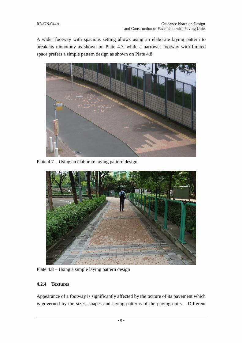
An appropriate laying pattern with feature bands could be adopted at a curved
footway to match with its curved character as shown on Plate 4.5. An abrupt change
in directions of laying patterns in localized area as shown on Plate 4.6 should be
avoided.
Plate 4.5 – Using transverse paving bands as transitional zones for aligning the
direction of a laying pattern with the curvature of a footway to provide visual
continuity
Plate 4.6 – Avoid using laying patterns with abrupt changes in direction
RD/GN/044A Guidance Notes on Design
and Construction of Pavements with Paving Units
- 8 -
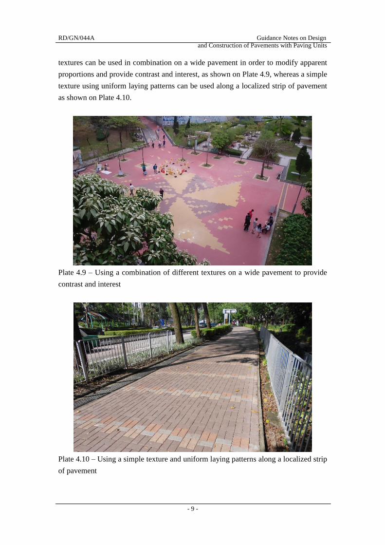
A wider footway with spacious setting allows using an elaborate laying pattern to
break its monotony as shown on Plate 4.7, while a narrower footway with limited
space prefers a simple pattern design as shown on Plate 4.8.
Plate 4.7 – Using an elaborate laying pattern design
Plate 4.8 – Using a simple laying pattern design
4.2.4 Textures
Appearance of a footway is significantly affected by the texture of its pavement which
is governed by the sizes, shapes and laying patterns of the paving units. Different
RD/GN/044A Guidance Notes on Design
and Construction of Pavements with Paving Units
- 9 -
textures can be used in combination on a wide pavement in order to modify apparent
proportions and provide contrast and interest, as shown on Plate 4.9, whereas a simple
texture using uniform laying patterns can be used along a localized strip of pavement
as shown on Plate 4.10.
Plate 4.9 – Using a combination of different textures on a wide pavement to provide
contrast and interest
Plate 4.10 – Using a simple texture and uniform laying patterns along a localized strip
of pavement
RD/GN/044A Guidance Notes on Design
and Construction of Pavements with Paving Units
- 10 -
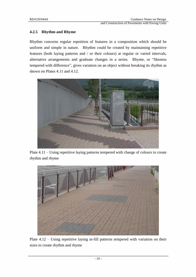
4.2.5 Rhythm and Rhyme
Rhythm concerns regular repetition of features in a composition which should be
uniform and simple in nature. Rhythm could be created by maintaining repetitive
features (both laying patterns and / or their colours) at regular or varied intervals,
alternative arrangements and graduate changes in a series. Rhyme, or “likeness
tempered with difference”, gives variation on an object without breaking its rhythm as
shown on Plates 4.11 and 4.12.
Plate 4.11 – Using repetitive laying patterns tempered with change of colours to create
rhythm and rhyme
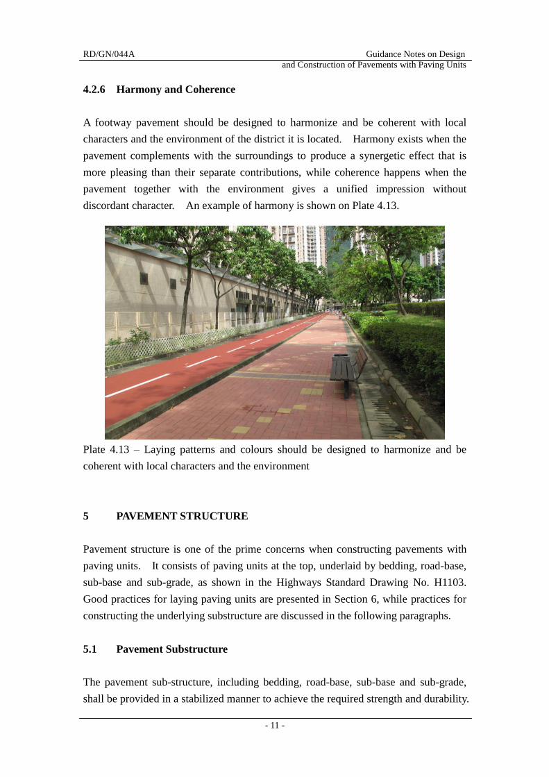
Plate 4.12 – Using repetitive laying in-fill patterns tempered with variation on their
sizes to create rhythm and rhyme
RD/GN/044A Guidance Notes on Design
and Construction of Pavements with Paving Units
- 11 -
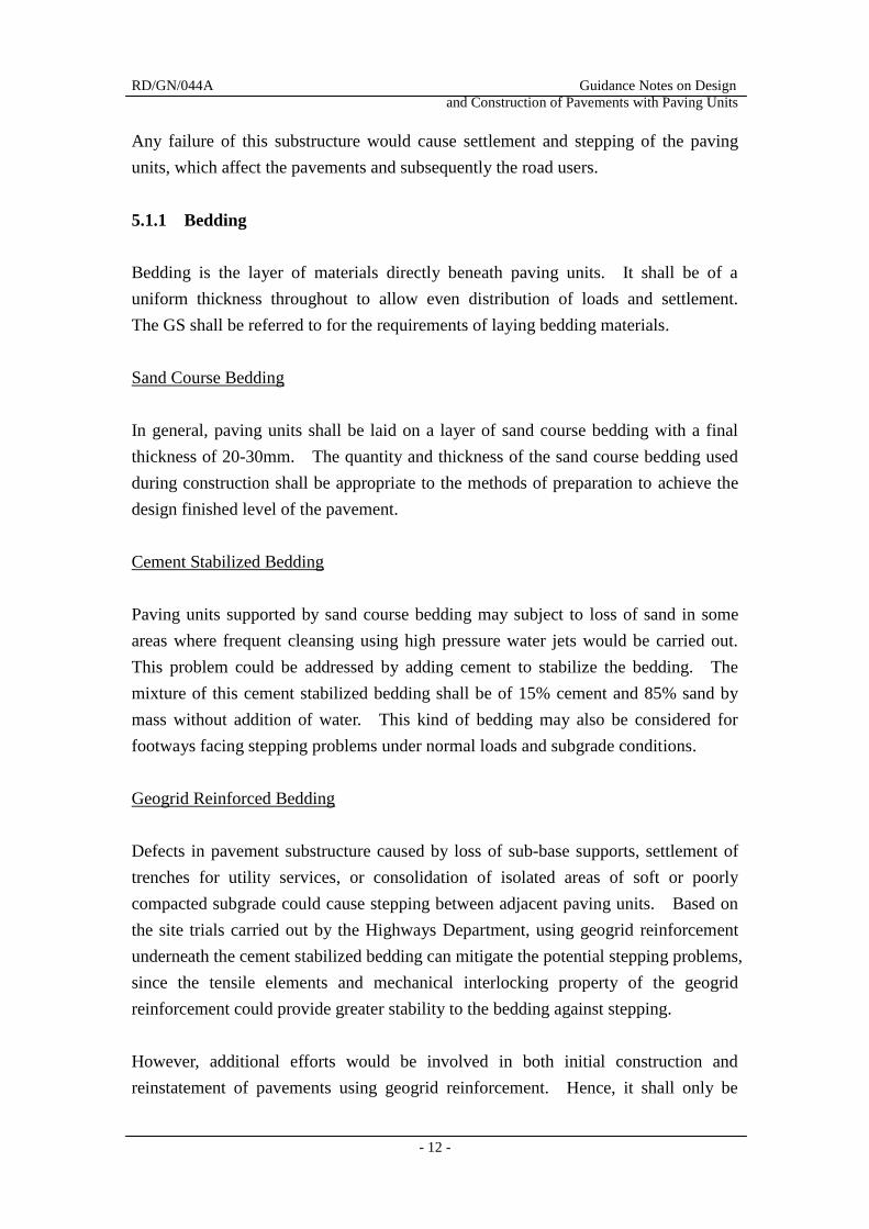
4.2.6 Harmony and Coherence
A footway pavement should be designed to harmonize and be coherent with local
characters and the environment of the district it is located. Harmony exists when the
pavement complements with the surroundings to produce a synergetic effect that is
more pleasing than their separate contributions, while coherence happens when the
pavement together with the environment gives a unified impression without
discordant character. An example of harmony is shown on Plate 4.13.
Plate 4.13 – Laying patterns and colours should be designed to harmonize and be
coherent with local characters and the environment
5 PAVEMENT STRUCTURE
Pavement structure is one of the prime concerns when constructing pavements with
paving units. It consists of paving units at the top, underlaid by bedding, road-base,
sub-base and sub-grade, as shown in the Highways Standard Drawing No. H1103.
Good practices for laying paving units are presented in Section 6, while practices for
constructing the underlying substructure are discussed in the following paragraphs.
5.1 Pavement Substructure
The pavement sub-structure, including bedding, road-base, sub-base and sub-grade,
shall be provided in a stabilized manner to achieve the required strength and durability.
RD/GN/044A Guidance Notes on Design
and Construction of Pavements with Paving Units
- 12 -
Any failure of this substructure would cause settlement and stepping of the paving
units, which affect the pavements and subsequently the road users.
5.1.1 Bedding
Bedding is the layer of materials directly beneath paving units. It shall be of a
uniform thickness throughout to allow even distribution of loads and settlement.
The GS shall be referred to for the requirements of laying bedding materials.
Sand Course Bedding
In general, paving units shall be laid on a layer of sand course bedding with a final
thickness of 20-30mm. The quantity and thickness of the sand course bedding used
during construction shall be appropriate to the methods of preparation to achieve the
design finished level of the pavement.
Cement Stabilized Bedding
Paving units supported by sand course bedding may subject to loss of sand in some
areas where frequent cleansing using high pressure water jets would be carried out.
This problem could be addressed by adding cement to stabilize the bedding. The
mixture of this cement stabilized bedding shall be of 15% cement and 85% sand by
mass without addition of water. This kind of bedding may also be considered for
footways facing stepping problems under normal loads and subgrade conditions.
Geogrid Reinforced Bedding
Defects in pavement substructure caused by loss of sub-base supports, settlement of
trenches for utility services, or consolidation of isolated areas of soft or poorly
compacted subgrade could cause stepping between adjacent paving units. Based on
the site trials carried out by the Highways Department, using geogrid reinforcement
underneath the cement stabilized bedding can mitigate the potential stepping problems,
since the tensile elements and mechanical interlocking property of the geogrid
reinforcement could provide greater stability to the bedding against stepping.
However, additional efforts would be involved in both initial construction and
reinstatement of pavements using geogrid reinforcement. Hence, it shall only be
RD/GN/044A Guidance Notes on Design
and Construction of Pavements with Paving Units
- 13 -
applied on a case-by-case basis for areas with repeated stepping problems or difficult
to be maintained due to high pedestrian traffic. The Highways Department Standard
Drawing Nos. H5136 and H5137 provide details for laying paving units with geogrid
reinforcement for new works and reinstatement works respectively.
5.1.2 Road-base and Sub-base
Road-base is a bituminous or concrete layer between bedding and granular sub-base
for construction of carriageways and run-ins. It is normally 100 to 200mm minimum
thickness overlaid on a 225mm thick sub-base. Road-base is usually not required for
footways construction, where a 100mm thick sub-base should be provided directly
underneath the bedding. The Highways Department Standard Drawing No. H1103
and the GS give typical arrangements of road-base and sub-base for laying paving
units and the requirements for constructing these road-base and sub-base layers.
5.1.3 Sub-grade
Sub-grade is the bottom layer supporting the substructure for pavements laying with
paving units. The minimum elastic modulus of the sub-grade shall be 50MPa. For
the case that it cannot be achieved, strengthening measures to the sub-grade as
recommended under the Highways Department Guidance Notes No. RD/GN/042
should be provided.
5.2 Special Considerations
Some special considerations are required to be taken into account when designing
pavements laying with paving units for the areas subject to heavy loading or abnormal
operational conditions.
5.2.1 Carriageways and Run-in
Based on laboratory research and observations on pavements using paving units for
vehicular over-runs, it was found that opening of joints perpendicular to and
horizontal creep of paving units along the direction of the predominant traffic flow are
the two common modes of pavement failures. Selecting appropriate types of paving
units and laying paving units with appropriate patterns would be useful to minimize
their occurrence. In general, Type A precast concrete paving units would have better
RD/GN/044A Guidance Notes on Design
and Construction of Pavements with Paving Units
- 14 -
performance than Type B, and the herringbone bond laying pattern would perform far
better than other laying patterns, as illustrated in the Highways Department Standard
Drawing No. H5134.
To further avoid cracking or breaking of paving units exposed to vehicular traffic,
heavy duty paving units as specified in the Highways Department Standard Drawing
No. H5135 and as required under the GS shall be used. The Highways Department
Standard Drawing Nos. H5125, H5126 and H5133 also provide other construction
details for pavements using paving units with vehicular over-runs.
5.2.2 Joint Stabilizing Sealers
Joint stabilizing sealers can be epoxy based materials or similar for filling into the
joints between paving units without adversely affect their colours or skid resistance.
Details of application are presented in the Highways Department Standard Drawing
No. H5127. As extra efforts would be required for application and removal of the
joint stabilizing sealers between paving units, they shall only be applied to the
situation for preventing jointing sand or bedding materials from being eroded by
water jet cleansing, or other specific reasons considered appropriate by the Regional
offices of the Highways Department.
6 GOOD PRACTICE FOR LAYING PAVING UNITS
Paving units should be laid in a proper manner to ensure performances of pavements
in the aspects of safety of pedestrians, aesthetic, operation and maintenance. Any
unsatisfactory workmanship on laying paving units would produce unpleasant feeling
or cause inconvenience to road users and require frequent repairing. The Highways
Department promulgated standard drawings and specifications to set down
requirements of laying paving units for pavements to ensure adequate laying
standards could be achieved. Some good practices based on past experience are
elaborated in the following paragraphs, which may serve as practice guidance for
laying paving units.
6.1 Cutting and Trimming
To minimize cutting and trimming, proper setting out of paving units to suit the sites
RD/GN/044A Guidance Notes on Design
and Construction of Pavements with Paving Units
- 15 -
with frequent checking on their alignments during laying should be done.
Ornamental fixtures (if any) used with paving units should also be carefully selected
to ensure their shapes and sizes are compatible with those of the paving units and their
laying patterns. Special attention should be paid on cutting and trimming, including
use of proper equipment such as hydraulic or mechanical block-splitters for precast
concrete paving units and multi-bladed-splitters for clay paving units, to achieve
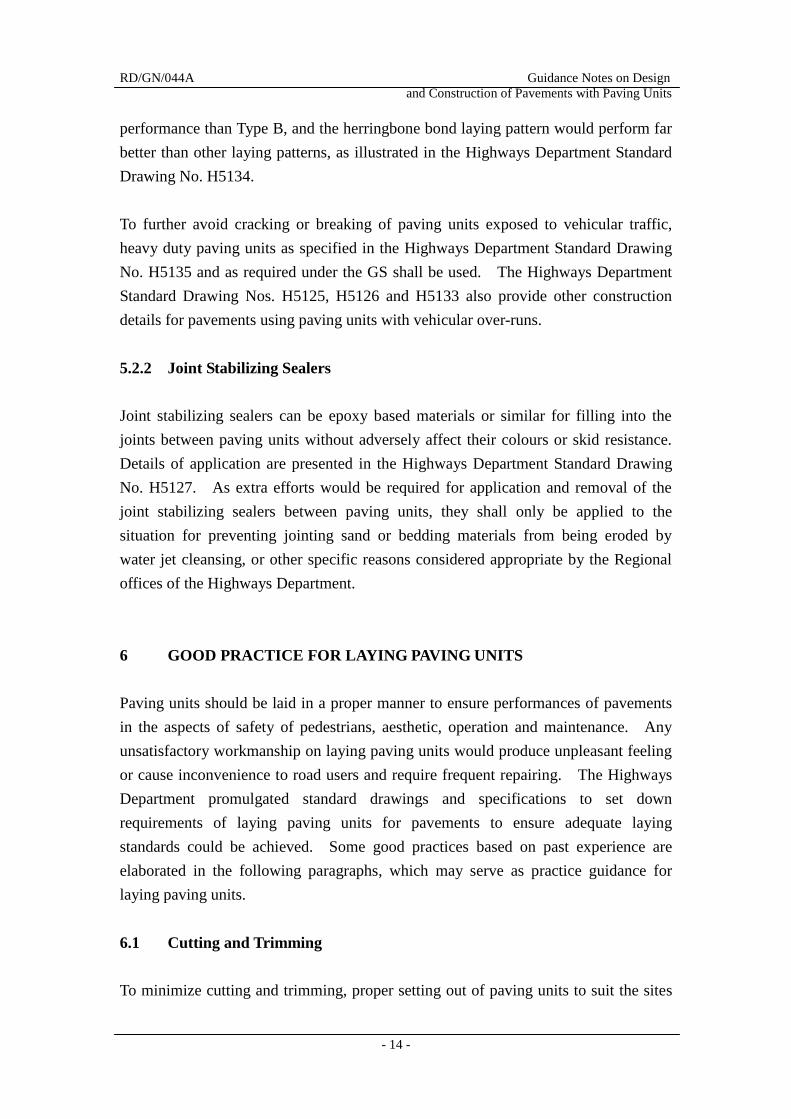
straight cutting faces. Besides, sizes of paving units should not be less than 1/4 of
their original sizes for laying 45o herringbone bond laying patterns, and not less than
1/3 of their original sizes for other laying patterns. Figure 6.1 provides some
examples of cutting paving units to suit different laying patterns.
Pre-fabricated or pre-cut paving units may be used in laying to minimize on-site
cutting. For example, half blocks and triangular blocks may be used for 90o
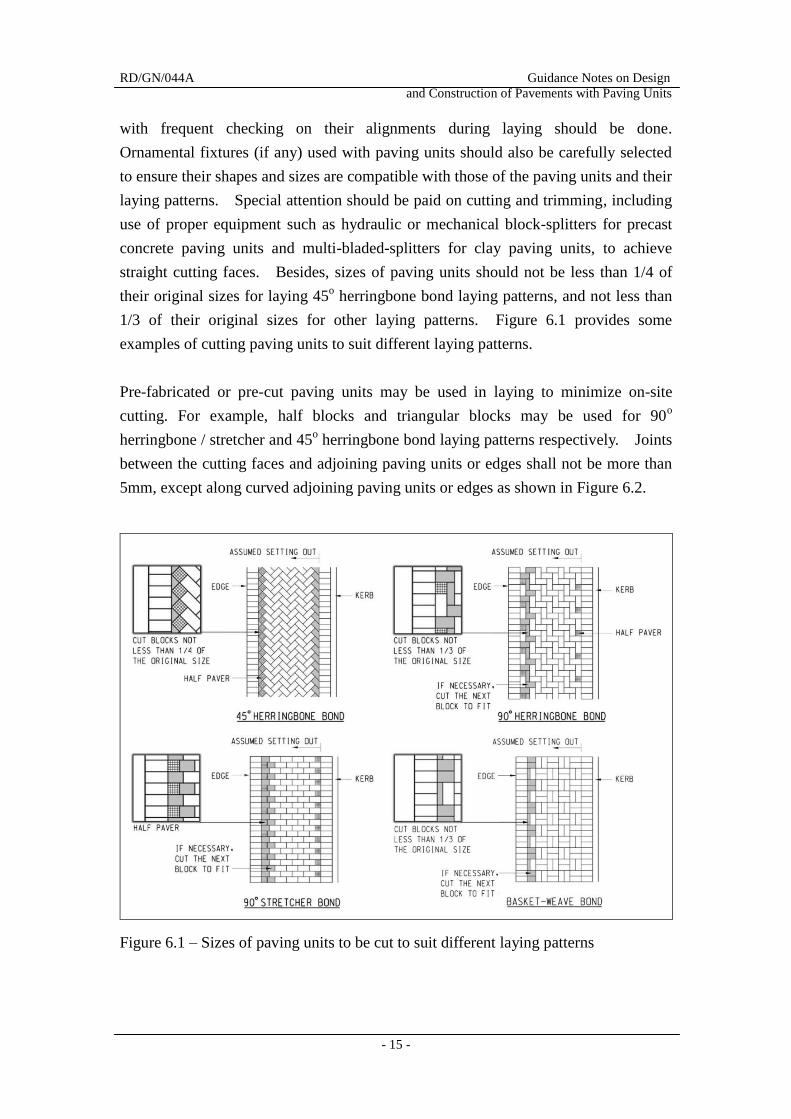
herringbone / stretcher and 45o herringbone bond laying patterns respectively. Joints
between the cutting faces and adjoining paving units or edges shall not be more than
5mm, except along curved adjoining paving units or edges as shown in Figure 6.2.
Figure 6.1 – Sizes of paving units to be cut to suit different laying patterns
RD/GN/044A Guidance Notes on Design
and Construction of Pavements with Paving Units
- 16 -
Figure 6.2 – Maximum allowable joint widths between cutting faces and adjoining
paving units / edges
6.2 Edge Restraints
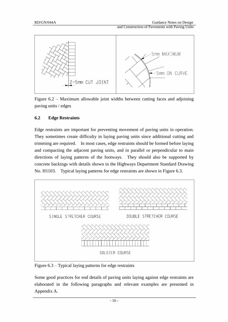
Edge restraints are important for preventing movement of paving units in operation.
They sometimes create difficulty in laying paving units since additional cutting and
trimming are required. In most cases, edge restraints should be formed before laying
and compacting the adjacent paving units, and in parallel or perpendicular to main
directions of laying patterns of the footways. They should also be supported by
concrete backings with details shown in the Highways Department Standard Drawing
No. H1103. Typical laying patterns for edge restraints are shown in Figure 6.3.
Figure 6.3 – Typical laying patterns for edge restraints
Some good practices for end details of paving units laying against edge restraints are
elaborated in the following paragraphs and relevant examples are presented in
Appendix A.
RD/GN/044A Guidance Notes on Design
and Construction of Pavements with Paving Units
- 17 -
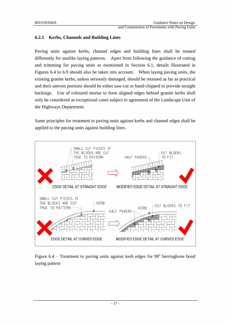
6.2.1 Kerbs, Channels and Building Lines
Paving units against kerbs, channel edges and building lines shall be treated
differently for unalike laying patterns. Apart from following the guidance of cutting
and trimming for paving units as mentioned in Section 6.1, details illustrated in
Figures 6.4 to 6.9 should also be taken into account. When laying paving units, the
existing granite kerbs, unless seriously damaged, should be retained as far as practical
and their uneven portions should be either saw-cut or hand-chipped to provide straight
backings. Use of coloured mortar to form aligned edges behind granite kerbs shall
only be considered as exceptional cases subject to agreement of the Landscape Unit of
the Highways Department.
Same principles for treatment to paving units against kerbs and channel edges shall be
applied to the paving units against building lines.
Figure 6.4 – Treatment to paving units against kerb edges for 90o herringbone bond
laying pattern
RD/GN/044A Guidance Notes on Design
and Construction of Pavements with Paving Units
- 18 -
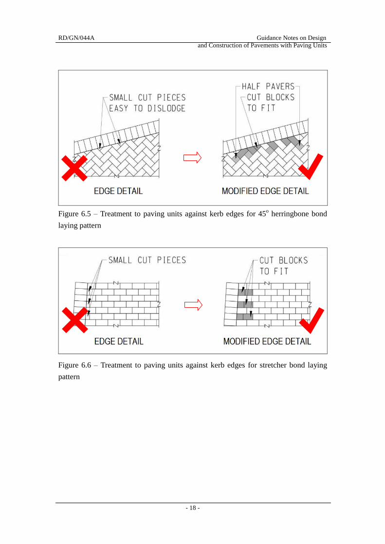
Figure 6.5 – Treatment to paving units against kerb edges for 45o herringbone bond
laying pattern
Figure 6.6 – Treatment to paving units against kerb edges for stretcher bond laying
pattern
RD/GN/044A Guidance Notes on Design
and Construction of Pavements with Paving Units
- 19 -
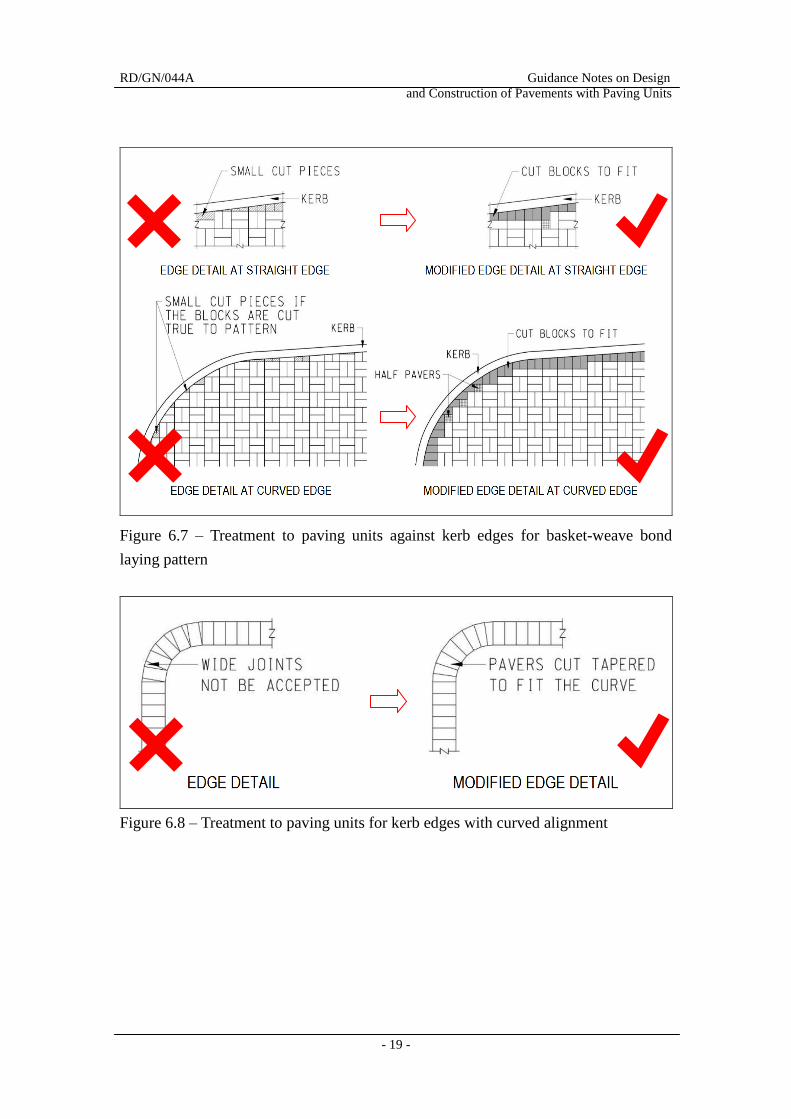
Figure 6.7 – Treatment to paving units against kerb edges for basket-weave bond
laying pattern
Figure 6.8 – Treatment to paving units for kerb edges with curved alignment
RD/GN/044A Guidance Notes on Design
and Construction of Pavements with Paving Units
- 20 -
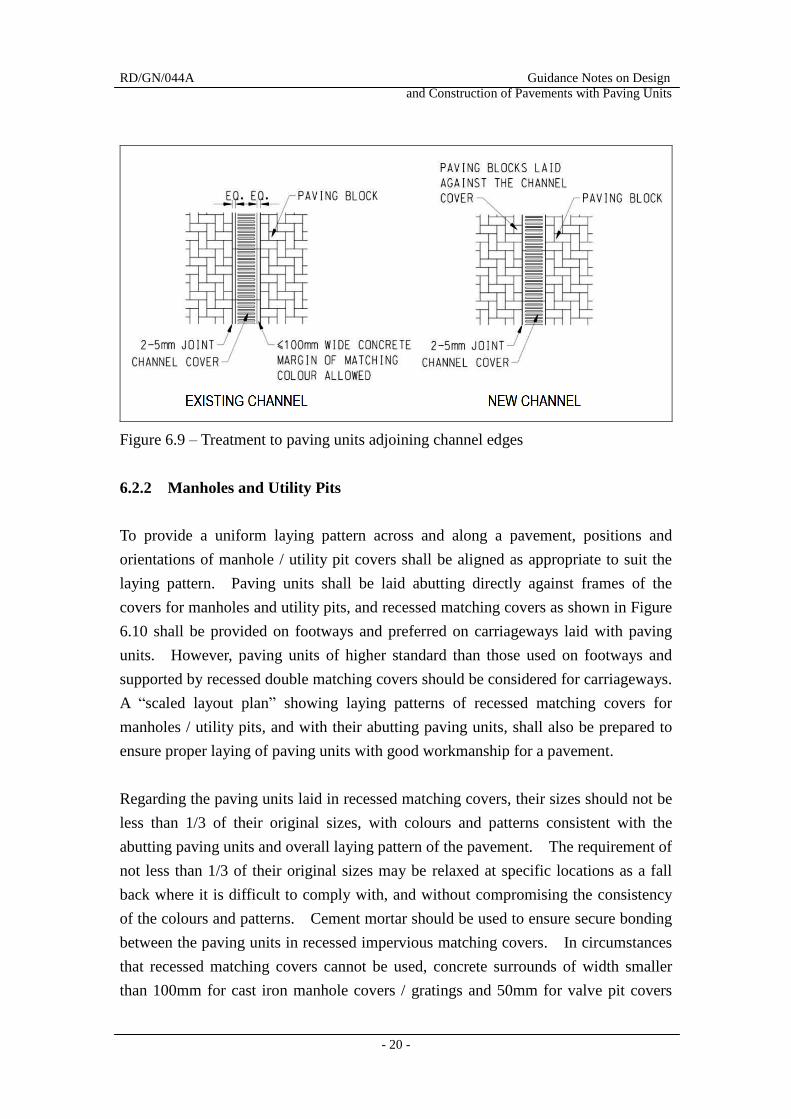
Figure 6.9 – Treatment to paving units adjoining channel edges
6.2.2 Manholes and Utility Pits
To provide a uniform laying pattern across and along a pavement, positions and
orientations of manhole / utility pit covers shall be aligned as appropriate to suit the
laying pattern. Paving units shall be laid abutting directly against frames of the
covers for manholes and utility pits, and recessed matching covers as shown in Figure
6.10 shall be provided on footways and preferred on carriageways laid with paving
units. However, paving units of higher standard than those used on footways and
supported by recessed double matching covers should be considered for carriageways.
A “scaled layout plan” showing laying patterns of recessed matching covers for
manholes / utility pits, and with their abutting paving units, shall also be prepared to
ensure proper laying of paving units with good workmanship for a pavement.
Regarding the paving units laid in recessed matching covers, their sizes should not be
less than 1/3 of their original sizes, with colours and patterns consistent with the
abutting paving units and overall laying pattern of the pavement. The requirement of
not less than 1/3 of their original sizes may be relaxed at specific locations as a fall
back where it is difficult to comply with, and without compromising the consistency
of the colours and patterns. Cement mortar should be used to ensure secure bonding
between the paving units in recessed impervious matching covers. In circumstances
that recessed matching covers cannot be used, concrete surrounds of width smaller
than 100mm for cast iron manhole covers / gratings and 50mm for valve pit covers
RD/GN/044A Guidance Notes on Design
and Construction of Pavements with Paving Units
- 21 -
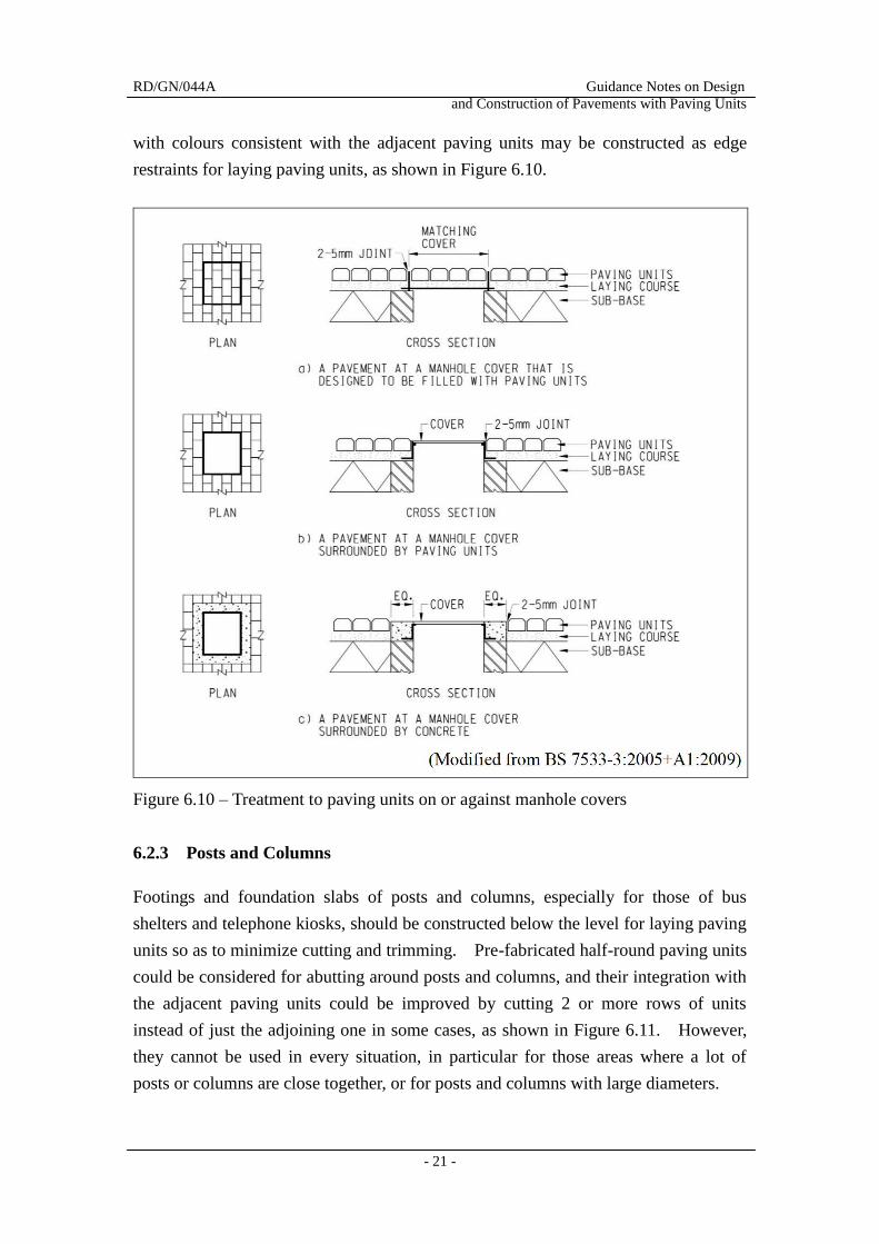
with colours consistent with the adjacent paving units may be constructed as edge
restraints for laying paving units, as shown in Figure 6.10.
Figure 6.10 – Treatment to paving units on or against manhole covers
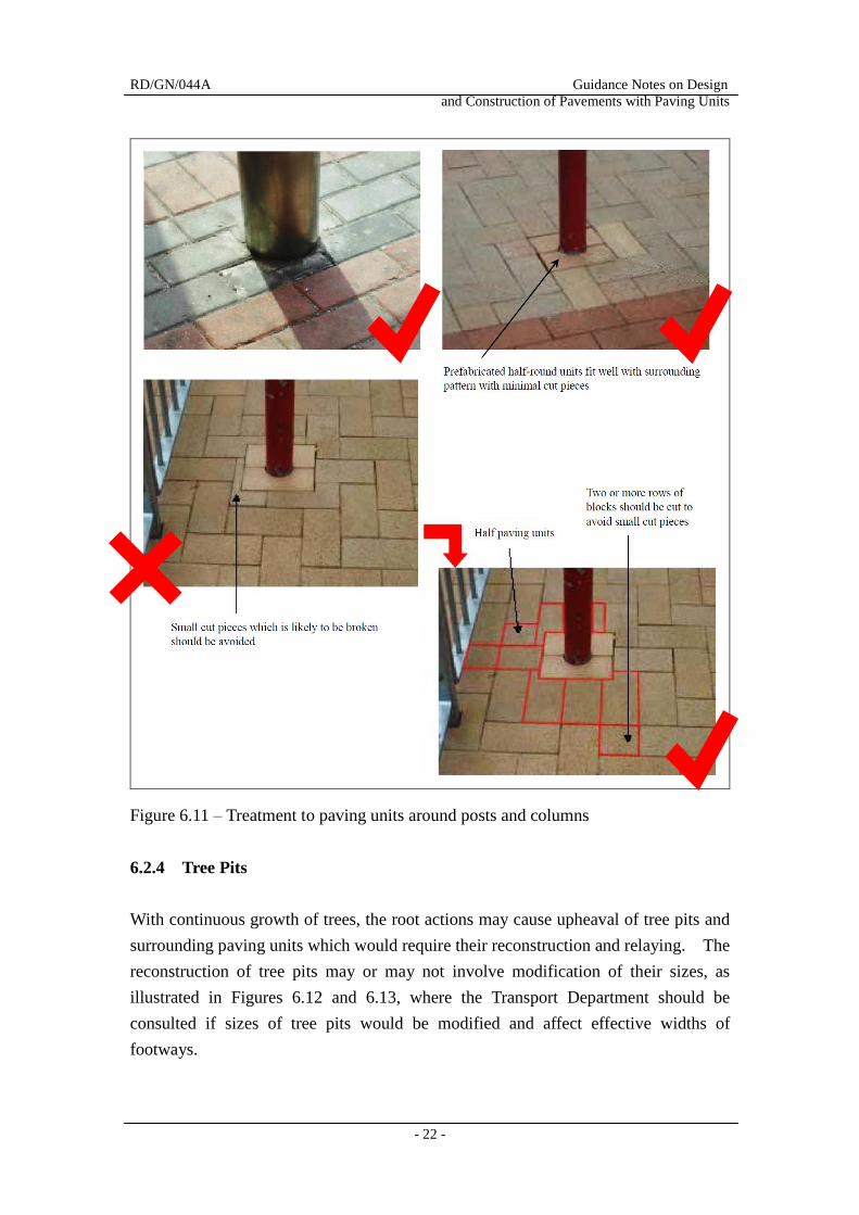
6.2.3 Posts and Columns
Footings and foundation slabs of posts and columns, especially for those of bus
shelters and telephone kiosks, should be constructed below the level for laying paving
units so as to minimize cutting and trimming. Pre-fabricated half-round paving units
could be considered for abutting around posts and columns, and their integration with
the adjacent paving units could be improved by cutting 2 or more rows of units
instead of just the adjoining one in some cases, as shown in Figure 6.11. However,
they cannot be used in every situation, in particular for those areas where a lot of
posts or columns are close together, or for posts and columns with large diameters.
RD/GN/044A Guidance Notes on Design
and Construction of Pavements with Paving Units
- 22 -
Figure 6.11 – Treatment to paving units around posts and columns
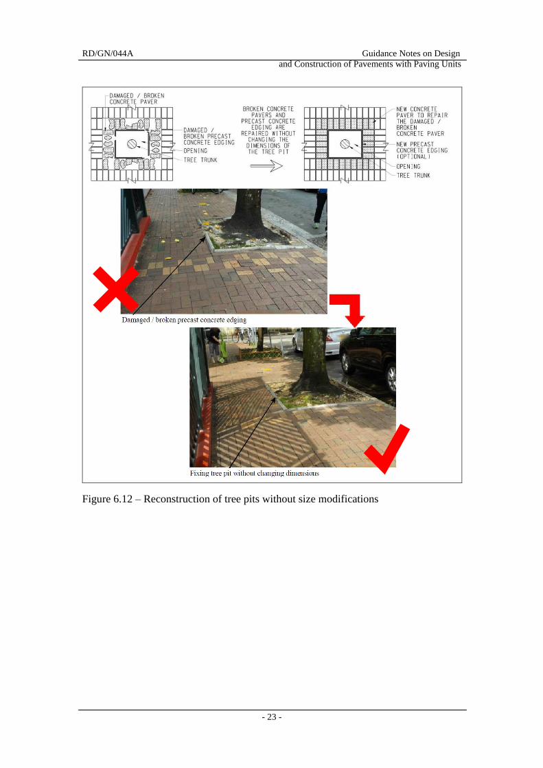
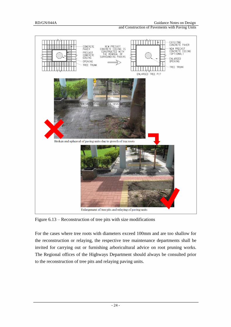
6.2.4 Tree Pits
With continuous growth of trees, the root actions may cause upheaval of tree pits and
surrounding paving units which would require their reconstruction and relaying. The
reconstruction of tree pits may or may not involve modification of their sizes, as
illustrated in Figures 6.12 and 6.13, where the Transport Department should be
consulted if sizes of tree pits would be modified and affect effective widths of
footways.
RD/GN/044A Guidance Notes on Design
and Construction of Pavements with Paving Units
- 23 -
Figure 6.12 – Reconstruction of tree pits without size modifications
RD/GN/044A Guidance Notes on Design
and Construction of Pavements with Paving Units
- 24 -
Figure 6.13 – Reconstruction of tree pits with size modifications
For the cases where tree roots with diameters exceed 100mm and are too shallow for
the reconstruction or relaying, the respective tree maintenance departments shall be
invited for carrying out or furnishing arboricultural advice on root pruning works.
The Regional offices of the Highways Department should always be consulted prior
to the reconstruction of tree pits and relaying paving units.
RD/GN/044A Guidance Notes on Design
and Construction of Pavements with Paving Units
- 25 -
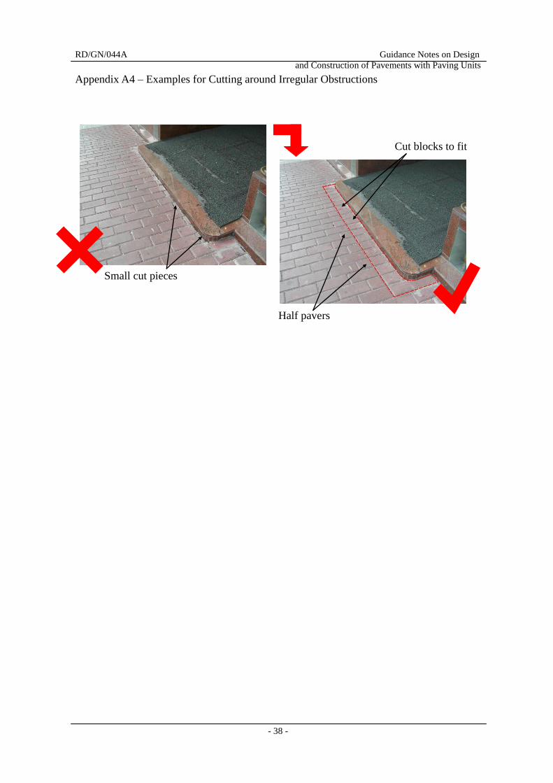
6.2.5 Irregular Obstructions
Irregular obstructions include holes for roller shutters, building extension and
protrusions of ironworks, etc.. Paving units shall be cut to fit and abut irregular
obstructions with 2 to 5mm joints in between. To provide structural integrity,
100mm wide concrete surrounds of thicknesses not less than those of and with colours
consistent with the adjacent paving units should be constructed.
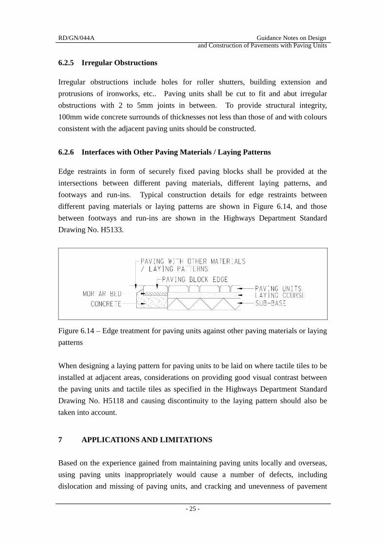
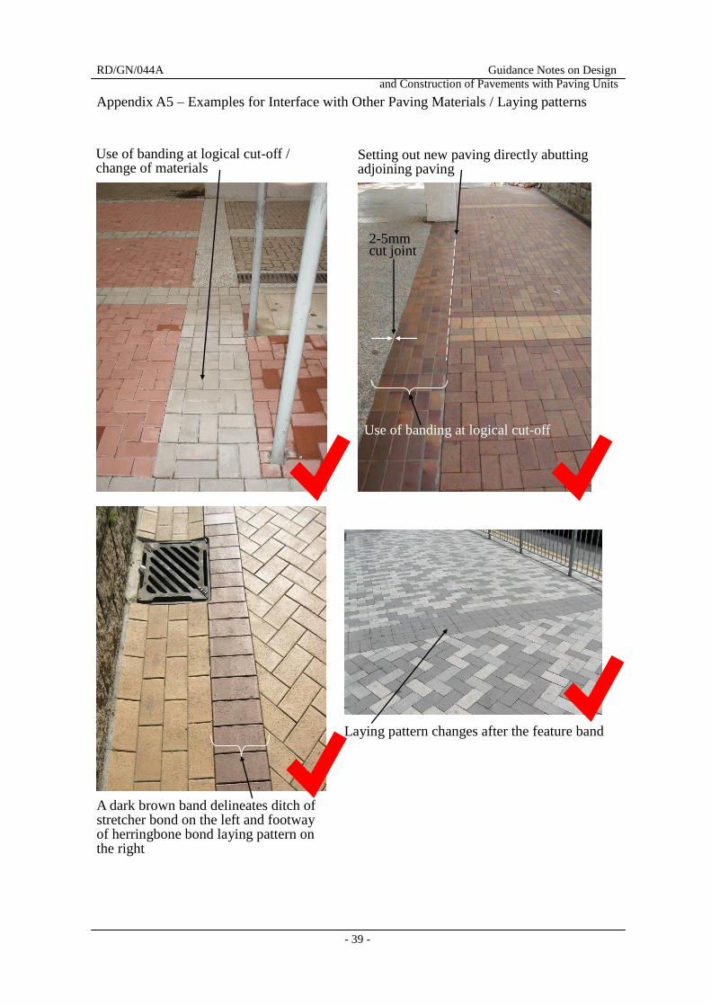
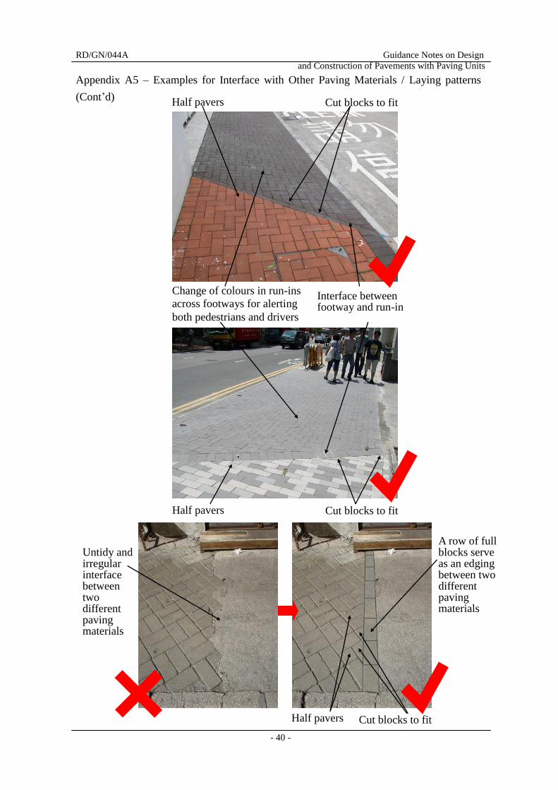
6.2.6 Interfaces with Other Paving Materials / Laying Patterns
Edge restraints in form of securely fixed paving blocks shall be provided at the
intersections between different paving materials, different laying patterns, and
footways and run-ins. Typical construction details for edge restraints between
different paving materials or laying patterns are shown in Figure 6.14, and those
between footways and run-ins are shown in the Highways Department Standard
Drawing No. H5133.
Figure 6.14 – Edge treatment for paving units against other paving materials or laying
patterns
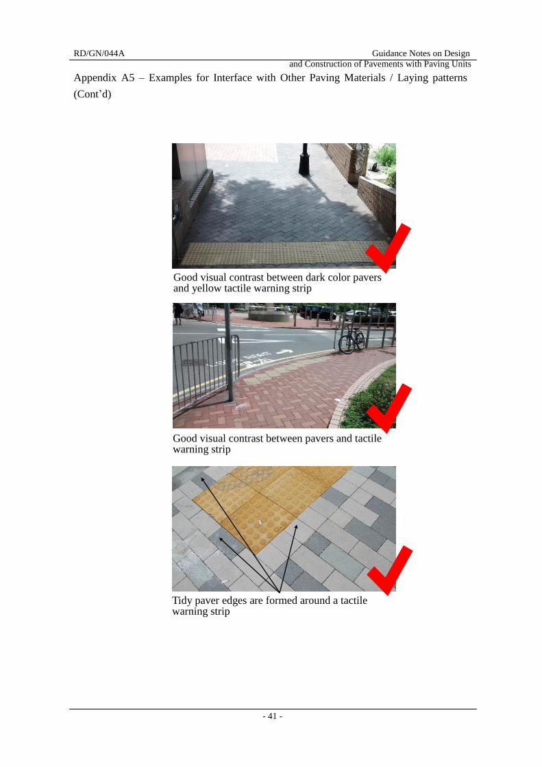
When designing a laying pattern for paving units to be laid on where tactile tiles to be
installed at adjacent areas, considerations on providing good visual contrast between
the paving units and tactile tiles as specified in the Highways Department Standard
Drawing No. H5118 and causing discontinuity to the laying pattern should also be
taken into account.
7 APPLICATIONS AND LIMITATIONS
Based on the experience gained from maintaining paving units locally and overseas,
using paving units inappropriately would cause a number of defects, including
dislocation and missing of paving units, and cracking and unevenness of pavement
RD/GN/044A Guidance Notes on Design
and Construction of Pavements with Paving Units
- 26 -
surfaces. Common defects of paving units with possible causes and recommended
remedies are described in the Highways Department Guidance Notes No. RD/GN/015.
General guidance, in terms of applications and limitations, for good design and
practice for laying paving units, are described in the following paragraphs.
7.1 Applications
Paving units are suitable for areas where aesthetic considerations are important and
where there are ongoing settlement or uneven ground displacement, frequent
disturbance by utility services and poor accessibility of conventional construction
plants.
7.1.1 Aesthetics
The aesthetic benefits brought by using paving units are discussed in Section 4.
Since paving units can offer different sizes, colours, textures and laying patterns, they
can provide flexible design to blend in with the surroundings.
7.1.2 Ongoing Settlement or Uneven Ground Displacement
Reclaimed areas or fills are always subject to ongoing vertical or differential
settlement which causes uneven pavement surfaces. The uneven pavement surfaces
could be easily rectified by removing and replacing paving units after leveling and
compacting the pavement substructure. The Port of Rotterdam in Holland which
was built at a reclaimed area from the sea demonstrates satisfactory performances of
using paving units on strengthened road-base and sub-base layers.
7.1.3 Frequent Disturbance by Utilities
Use of paving units on areas subject to frequent trench excavation is beneficial in that
it could minimize noise and construction waste generation when comparing with
concrete pavements. The considerable time required for setting and curing of
concrete for trench reinstatement could also be saved. As paving units are reused,
there is no noticeable colour or texture difference between reinstated areas and the
adjacent original paving areas.
RD/GN/044A Guidance Notes on Design
and Construction of Pavements with Paving Units
- 27 -
7.1.4 Poor Accessibility of Conventional Construction Plants
In remote areas such as outlying islands where access for conventional construction
plants or application of normal construction materials is difficult, use of paving units
is beneficial since only minimal basic construction equipment is required for skilled
labour to lay paving units by hand.
7.2 Limitations
Paving units may not be suitable for use in some areas of footways, carriageways and
industrial areas where they are easily susceptible to damage or require frequent
maintenance.
7.2.1 Footways with Vulnerable Site Conditions
From past experience, the following site conditions may render the use of paving units
not appropriate:
(i) footways of steep gradients (say 8% or larger) or adjacent to slopes leading to
possible washout of jointing sand or bedding materials during rainstorms;
(ii) footways on embankments or at crest of filled slopes causing possible instability
of embankments or slopes by infiltrated rainwater during heavy storms;
(iii) footways with problems of underground seepage or subject to frequent ponding
or pouring of water, such as wet food stalls in markets;
(iv) footways with considerable numbers of utility pits or street furniture which pose
difficulties in achieving proper laying of paving units and compaction of
pavement substructure around the pits and street furniture;
(v) footways likely to be stained by oil or fuel spillage, including petrol station
forecourts, fronting of car repairing shops and markets, where use of paving
units may lead to extra difficulty on cleansing;
(vi) footways likely to be occupied by cooked-food stalls or hawkers, or where
refuse collection points are situated; and
(vii) footways likely to have weeding problems at areas with low pedestrian usage,
for example, footways with high density of roadside planting at remote areas.
Notwithstanding the above, engineering judgment with appropriate measures could be
applied to facilitate the use of paving units under some of the aforesaid site conditions.
RD/GN/044A Guidance Notes on Design
and Construction of Pavements with Paving Units
- 28 -
For example, judgment could be made on authenticating suitability of laying paving
units for a footway under site condition (i) or (ii) with the following measures
provided:
- stabilization measures for jointing sand / bedding materials and preventing
dislocation of paving units during rainstorms for site condition (i);
- provision of drainage layers under embankments or filter blankets under filled
slopes to avoid building up pore water pressures during heavy storms to
enhance stability for site condition (ii).
Judgment with appropriate measures could also be applied to cope with site condition
(vii) since the weeding problems could be resolved by removal of weeds where its
cost and effort would sometimes be outweighed by the benefits brought by using
paving units as discussed in Section 7.1.
The Regional offices of the Highways Department should be consulted before using
paving units for these particular site conditions.
7.2.2 Carriageways
In general, paving units are confined to be used on vehicular run-ins and carriageways
with operational speeds not exceeding and not anticipated to approach 50km/h, since
a pavement constructed with paving units cannot offer an appropriate riding quality to
vehicles travel at higher speeds. Paving units in form of paving slabs are not
recommended to be used for vehicular passage due to their relatively low load bearing
capacity. The Highways Department Standard Drawing Nos. H1103, H5125 to
H5126, and H5133 to H5135 shall be referred to for laying paving units on vehicular
run-ins and carriageways.
7.2.3 Industrial Areas
Carriageways and footways located within industrial areas, which are subject to
frequent parking and loading / unloading activities, are not suitable for laying with
paving units because the heavy loading from trucks would cause severe deformation
and punching shear failures of the units.
RD/GN/044A Guidance Notes on Design
and Construction of Pavements with Paving Units
- 29 -
8 GUIDELINES TO AUTHORIZED PERSONS
The “Practice Note for Authorized Persons, Registered Structural Engineers and
Registered Geotechnical Engineers” APP-144 published by the Buildings Department
requires the Authorized Persons to follow the requirements of the Highways
Department for designing and constructing vehicular ingress and egress points on
public footways. The requirements of the Highways Department include the
guidance provided in this set of Guidance Notes, GS, standard drawings and particular
specifications published by the Highways Department. This set of Guidance Notes
and the standard drawings are available in the homepage of the Highways Department
(http://www.hyd.gov.hk/en/publications_and_publicity/publications/index.html), and
the particular specifications are enclosed in Appendix B. As the particular
specifications would be updated from time to time, the Authorized Persons should
consult the Regional offices of the Highways Department before application.
RD/GN/044A Guidance Notes on Design
and Construction of Pavements with Paving Units
- 30 -
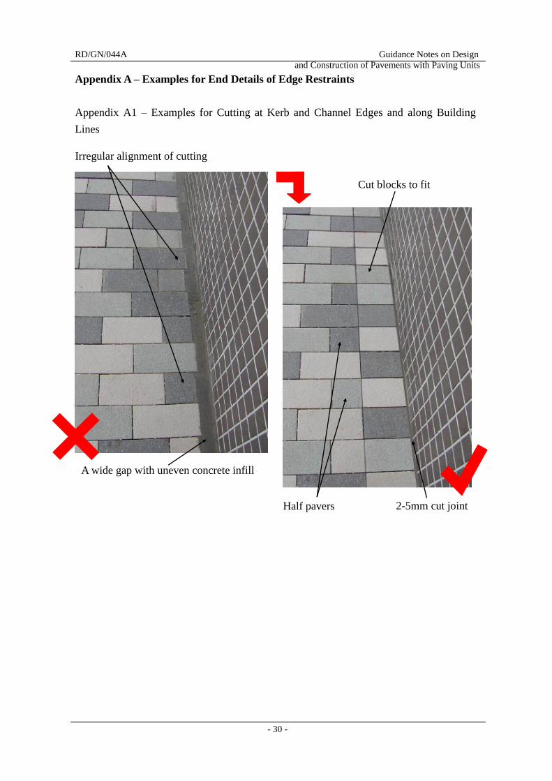
Appendix A – Examples for End Details of Edge Restraints
Appendix A1 – Examples for Cutting at Kerb and Channel Edges and along Building
Lines
2-5mm cut joint
Cut blocks to fit
Half pavers
Irregular alignment of cutting
A wide gap with uneven concrete infill
RD/GN/044A Guidance Notes on Design
and Construction of Pavements with Paving Units
- 31 -
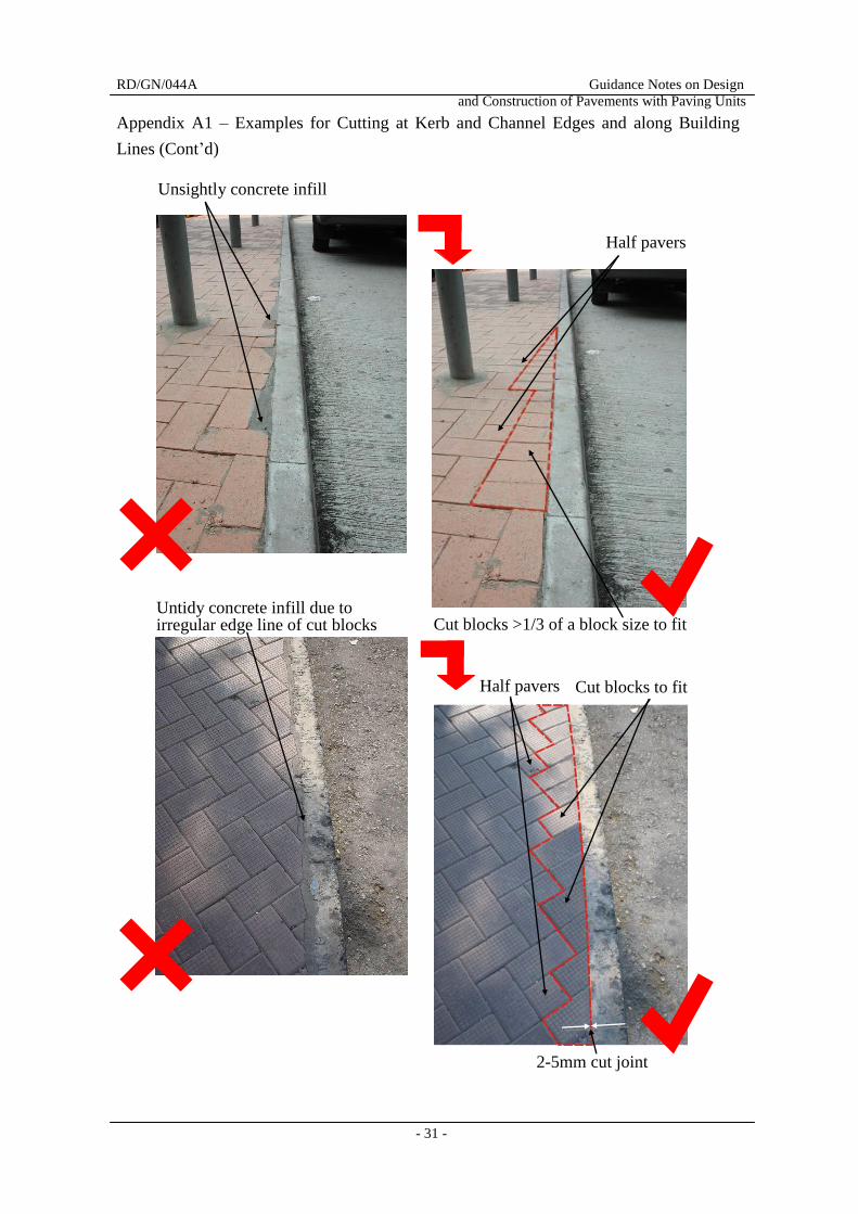
Appendix A1 – Examples for Cutting at Kerb and Channel Edges and along Building
Lines (Cont’d)
Unsightly concrete infill
Half pavers
Cut blocks >1/3 of a block size to fit Untidy concrete infill due to irregular edge line of cut blocks
Cut blocks to fit
2-5mm cut joint
Half pavers
RD/GN/044A Guidance Notes on Design
and Construction of Pavements with Paving Units
- 32 -
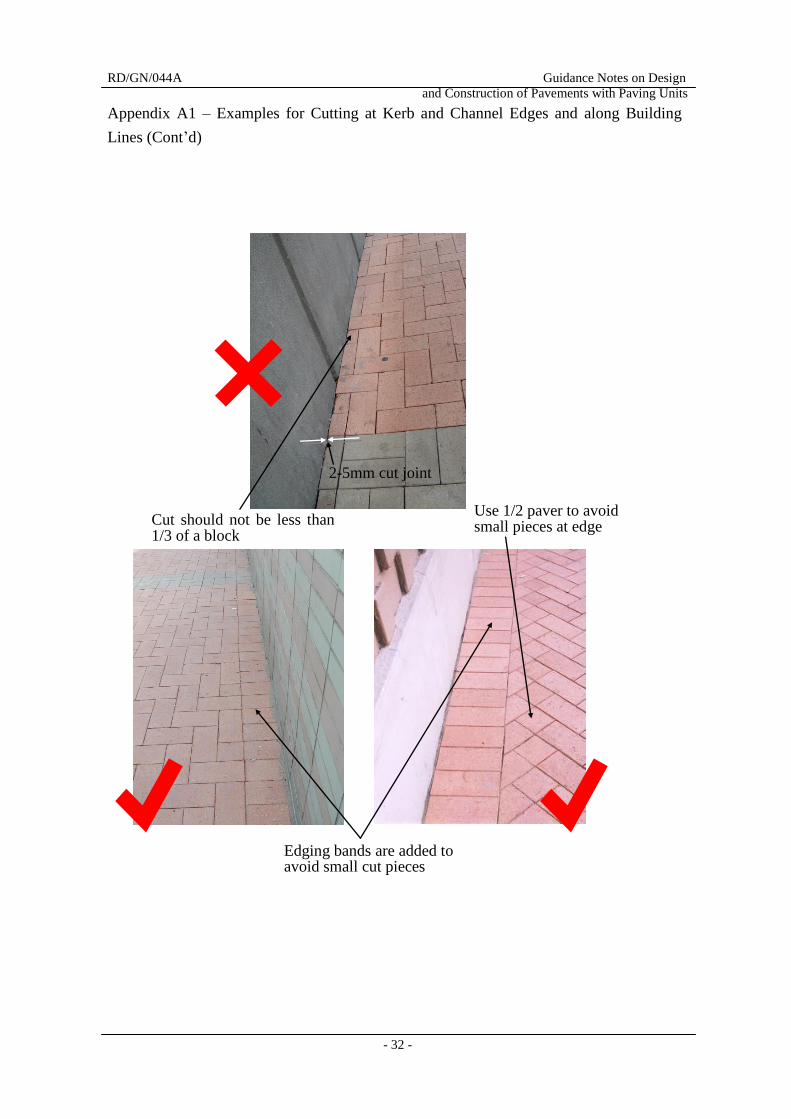
Appendix A1 – Examples for Cutting at Kerb and Channel Edges and along Building
Lines (Cont’d)
Cut should not be less than 1/3 of a block
Edging bands are added to avoid small cut pieces
Use 1/2 paver to avoid small pieces at edge
2-5mm cut joint
RD/GN/044A Guidance Notes on Design
and Construction of Pavements with Paving Units
- 33 -
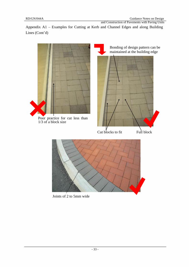
Appendix A1 – Examples for Cutting at Kerb and Channel Edges and along Building
Lines (Cont’d)
Bonding of design pattern can be
maintained at the building edge
Cut blocks to fit Full block
Poor practice for cut less than 1/3 of a block size
Joints of 2 to 5mm wide
RD/GN/044A Guidance Notes on Design
and Construction of Pavements with Paving Units
- 34 -
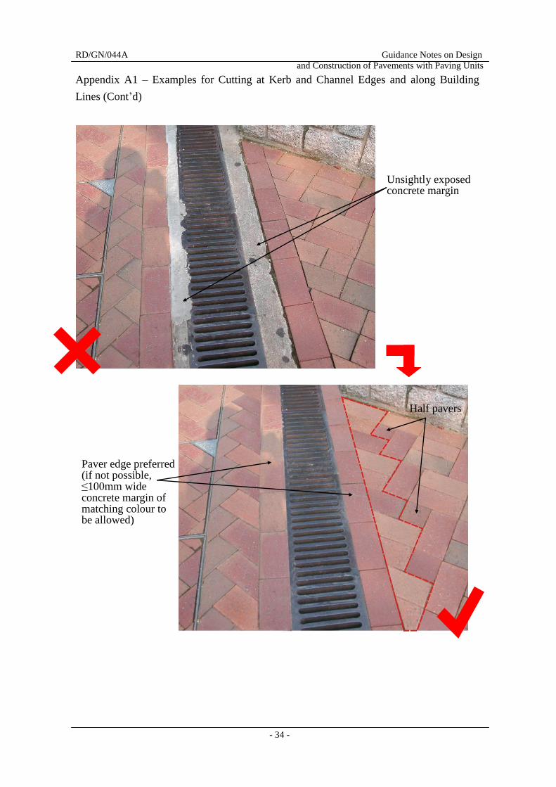
Appendix A1 – Examples for Cutting at Kerb and Channel Edges and along Building
Lines (Cont’d)
Unsightly exposed concrete margin
Paver edge preferred (if not possible, ≤100mm wide concrete margin of matching colour to be allowed)
Half pavers
RD/GN/044A Guidance Notes on Design
and Construction of Pavements with Paving Units
- 35 -
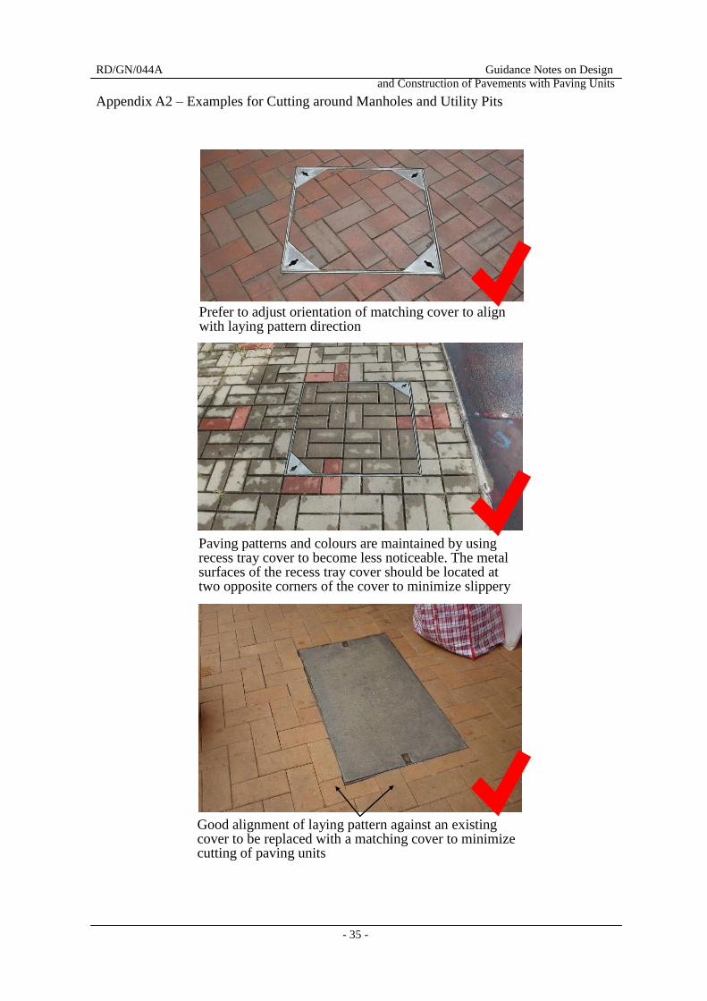
Appendix A2 – Examples for Cutting around Manholes and Utility Pits
Prefer to adjust orientation of matching cover to align with laying pattern direction
Paving patterns and colours are maintained by using recess tray cover to become less noticeable. The metal surfaces of the recess tray cover should be located at two opposite corners of the cover to minimize slippery
Good alignment of laying pattern against an existing cover to be replaced with a matching cover to minimize cutting of paving units
RD/GN/044A Guidance Notes on Design
and Construction of Pavements with Paving Units
- 36 -
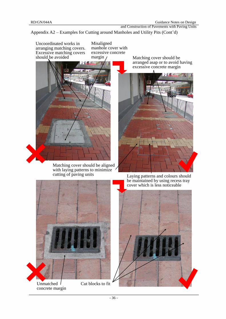
Appendix A2 – Examples for Cutting around Manholes and Utility Pits (Cont’d)
Uncoordinated works in arranging matching covers. Excessive matching covers should be avoided
Misaligned manhole cover with excessive concrete margin
Laying patterns and colours should be maintained by using recess tray cover which is less noticeable
Matching cover should be arranged asap or to avoid having excessive concrete margin
Cut blocks to fit
Matching cover should be aligned with laying patterns to minimize cutting of paving units
Unmatched concrete margin
RD/GN/044A Guidance Notes on Design
and Construction of Pavements with Paving Units
- 37 -
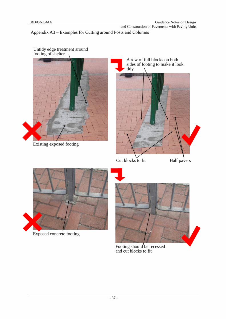
Appendix A3 – Examples for Cutting around Posts and Columns
Cut blocks to fit Half pavers
A row of full blocks on both sides of footing to make it look tidy
Untidy edge treatment around footing of shelter
Existing exposed footing
Exposed concrete footing
Footing should be recessed and cut blocks to fit
RD/GN/044A Guidance Notes on Design
and Construction of Pavements with Paving Units
- 38 -
Appendix A4 – Examples for Cutting around Irregular Obstructions
Small cut pieces
Half pavers
Cut blocks to fit
RD/GN/044A Guidance Notes on Design
and Construction of Pavements with Paving Units
- 39 -
Appendix A5 – Examples for Interface with Other Paving Materials / Laying patterns
Use of banding at logical cut-off
2-5mm cut joint
Use of banding at logical cut-off / change of materials
Laying pattern changes after the feature band
Setting out new paving directly abutting adjoining paving
A dark brown band delineates ditch of stretcher bond on the left and footway of herringbone bond laying pattern on the right
RD/GN/044A Guidance Notes on Design
and Construction of Pavements with Paving Units
- 40 -
(Cont’d)
Change of colours in run-ins
across footways for alerting
both pedestrians and drivers
Half pavers Cut blocks to fit
Interface between footway and run-in
Half pavers Cut blocks to fit
Untidy and irregular interface between two different paving materials
A row of full blocks serve as an edging between two different paving materials
Cut blocks to fit Half pavers
Appendix A5 – Examples for Interface with Other Paving Materials / Laying patterns
RD/GN/044A Guidance Notes on Design
and Construction of Pavements with Paving Units
- 41 -
Appendix A5 – Examples for Interface with Other Paving Materials / Laying patterns
(Cont’d)
Tidy paver edges are formed around a tactile warning strip
Good visual contrast between pavers and tactile warning strip
Good visual contrast between dark color pavers and yellow tactile warning strip
RD/GN/044A Guidance Notes on Design
and Construction of Pavements with Paving Units
- 42 -
Appendix B – Particular Specifications Published by the Highways Department
(2014 Edition)
Appendix B1 – General Requirements
GS Clause 11.01 is renumbered as GS Clause 11.01.03 and the following sub-clauses are
added before GS Clause 11.01.03:
11.01.01 GLOSSARY OF TERMS
Paver is a term used to described unit, clay paver, clay paving sett, artificial
granite paver, natural granite paver, tactile paving block/slab/sett, tactile clay
paver/paving sett, tactile artificial granite paving block/slab/sett, tactile natural
granite paving block/slab/sett and tactile tile unless otherwise specified by the
Engineer.
11.01.02 WORKERS ENGAGED IN LAYING PAVERS
(1) Workers engaged in laying pavers shall have satisfactorily completed
at least 14 hours of training in the past 3 years on laying of pavers
conducted by the Construction Industry Council or other equivalent
institution as approved by the Engineer.
(2) In the event that such training courses are not readily available, the
Contractor shall make their own arrangement with Construction
Industry Councilor other equivalent institutions as the case may be for
the organisation of such courses.
(3) The Contractor shall maintain the records of his workers who have
attended the training courses pursuant to sub-clause (1) and produce
the documentary proof of the training and identities of the trained
workers for inspection upon request by the Engineer’s site supervisory
staff. If the Contractor fails to produce the evidence of such record for
inspection, such worker shall be regarded as “helpers” and shall not be
engaged in laying pavers.
(4) In the event that the Contractor fails to comply with sub-clauses (1),
(2) or (3), the Engineer shall determine the reduction of an amount in
respect of any loss or damage suffered or likely to be suffered by the
Employer or any saving in cost to the Contractor, whichever is the
greater, as a result of such failure and deduct the same from the value
of the work done as if the work has been executed in accordance with
the Contract.
RD/GN/044A Guidance Notes on Design
and Construction of Pavements with Paving Units
- 43 -
Appendix B2 – Precast Concrete Paving Units
Part 7 of Section 11 of the GS is supplemented by the following:
11.60 UNIT
Replace Item (2) of GS Clause 11.60 by the following:
(2) Depending on their quality, units are classified as either Grade A or Grade
B as follows:
- Grade A units shall comply with GS Clauses 11.61 to 11.88.
- Grade B units shall comply with GS Clauses 11.61 to 11.65, 11.67,
11.68, 11.70 and 11.72 to 11.85.
11.62 PRECAST CONCRETE PAVING SLABS
Replace Item (2) of GS Clause 11.62 by the following:
(2) Paving slabs shall be 60 mm thick for footways and 80 mm thick for
carriageways and vehicular accesses. Paving slabs of other thickness may
be used if approved by the Engineer.
11.65 CONCRETE & USE OF RECYCLED AGGREGATES
Replace GS Clause 11.65 by the following:
(1) Concrete for paving units in footways and cycle tracks shall be Grade 30;
concrete for paving units in carriageways or areas to which vehicles will
have access shall be Grade 45.
(2) Aggregates for concrete shall comply with the following requirements:
(a) The aggregates shall contain not less than 70% by weight of recycled
aggregates.
(b) The recycled fine aggregates shall constitute not less than 40% by
weight of the total recycled aggregates. The recycled glass cullet
shall be included as recycled fine aggregates and shall constitute 20%
to 25% by weight of the total aggregates.
(c) The nominal maximum size of the aggregates shall be 10 mm.
RD/GN/044A Guidance Notes on Design
and Construction of Pavements with Paving Units
- 44 -
11.65 (2) (d) The recycled coarse aggregates shall be retained on a 5 mm BS test
sieve.
(e) The recycled fine aggregates shall all pass a 5 mm BS test sieve.
(f) The recycled glass cullet shall all pass a 3.35 mm BS test sieve and
shall be integrated with other constituents in such a manner that there
is no sharp edge nor burr exposed to put the pedestrians at risk when
the paving unit surface is eroded.
(g) The recycled aggregates shall contain not more than 0.5% of wood
and other materials less dense than water by using the manual sorting
test method in accordance with BRE Digest 433.
(h) The recycled aggregates shall contain not more than 1% of other
foreign materials (e.g. metals, plastics, clay lumps, asphalt and tar,
glass, etc.) by using the manual sorting test method in accordance
with BRE Digest 433.
(i) The recycled aggregates, except recycled glass cullet, shall be
recycled from inert construction and demolition materials sourced
from the fill banks managed by the Civil Engineering and
Development Department or other sources approved by the Engineer.
(j) The recycled glass cullet shall be produced from glass waste
generated from local sources approved by the Engineer.
(3) Each paving unit shall bear an inscribed mark for the identification purpose
that the unit contains recycled glass cullet of 20% to 25% by weight of the
total aggregates.
(4) Notwithstanding sub-clause (2) above,
(a) the Contractor may propose for the Engineer’s approval the use of
recycled fine aggregates without recycled glass cullet in the concrete
where there is a shortage of supply of recycled glass cullet; and/or
RD/GN/044A Guidance Notes on Design
and Construction of Pavements with Paving Units
- 45 -
11.65 (4) (b) the Contractor may propose for the Engineer’s approval the use of
virgin aggregates in lieu of recycled aggregates in the concrete when
there is a shortage of supply of recycled aggregates.
(5) Notwithstanding sub-clause (2) above, subject to the Engineer’s agreement,
the Contractor may use recycled fine aggregates without recycled glass
cullet in the concrete for the minor repair works to existing concrete pavers.
11.66 ADDITIONAL REQUIREMENTS FOR GRADE A UNITS
Replace Item (2) of GS Clause 11.66 by the following:
(2) Colour Pigments for Grade A units shall comply with BS EN 12878:2005.
They shall be UV-stable and shall be iron oxides, chrome oxide, titanium
oxide or cobalt aluminium oxide unless otherwise approved by the
Engineer.
11.68 PARTICULARS OF PAVING UNITS
Replace Item (1)(b) of GS Clause 11.68 by the following:
(1) (b) Certificates from the manufacturer showing the source and the
particle size distribution of the virgin and recycled aggregates,
Add the following to the Item (1)(e) and (f) of GS Clause 11.68
(e) A statement of compliance from the manufacturer as follows
showing that the manufacturer has put in place a system to assure
that the paving units contain 20% to 25 % of recycled glass cullet
by weight of the total aggregates:
- the statement of compliance shall be issued by an independent
assessment body with recognized status (e.g. Hong Kong
Productivity Council, Hong Kong Quality Assurance Agency,
etc.) with a validity period of 6 months from the date of issue.
The independent assessment body shall be approved by the
Engineer.
RD/GN/044A Guidance Notes on Design
and Construction of Pavements with Paving Units
- 46 -
11.68 (1) (f) Where the percentages of recycled aggregates, recycled fine
aggregates and recycled glass as specified in PS Clauses 11.65(2)
(a) and (b) cannot be fully complied with due to shortage in
supply of the respective recycled materials in the market, the
Contractor shall submit the following additional particulars to the
Engineer:
- a written confirmation from the manufacturer confirming the
shortage in supply of the respective recycled materials in the
market; and
- the proposed quantities of paving units for which the recycled
materials as specified in PS Clauses 11.65(2) (a) and (b)
cannot be fully complied with.
11.69 PARTICULARS OF UNITS - ADDITIONAL REQUIREMENTS FOR
GRADE A UNITS
Replace the 6
th Bullet Point of Item (1)(a) of GS Clause 11.69 by the following:
- 24-hour cold water absorption value of paving slabs, blocks
and setts to AS/NZS 4456.14:2003; and
11.74 LAYING UNITS
Add the following to GS Clause 11.74:
(8) The units shall be laid to “Guidelines on Good Practice for Laying Unit
Pavers” published by Highways Department.
(9) Unless otherwise agreed by the Engineer, paving unit abutting traffic sign
posts, traffic signal poles, lamp posts, or street name plate supports or the
like shall be either prefabricated half-round units (where available) or cut
in a circular manner to match with the diameter of the posts/poles and
supports. The adjacent row/rows of paving units may need to be cut to
match smoothly with the other paving units. Where such cutting will
result in small units (any one dimension less than 1/3 of the original), at
least two rows will need to be cut.
RD/GN/044A Guidance Notes on Design
and Construction of Pavements with Paving Units
- 47 -
(10) Where cutting of paving blocks is required at the edge of manholes or
within recessed manhole covers for edge treatment, the size of the cut
blocks shall not be less than 1/3 of the original size. If necessary,
adjacent blocks shall also be cut to achieve the above requirement.
11.85 COMPRESSIVE STRENGTH TEST OF PAVING BLOCKS
Replace Item (1) of GS Clause 11.85 by the following:
(1) One sample of units in a batch shall be provided from every 1000 m
2 of
units or part thereof. A batch with units for area(s) less than 1000 m2 may
be added to the untested previous or following batch(es) as the case may
be for testing purposes. The number of specimens in each sample shall be
8. For paving blocks of size 200 x 200 x 60mm or 80mm, specimens of
size 200 x 100 x 60mm or 80mm shall be cut from these blocks in
accordance with GS Clause 11.74 (6) to form samples.
11.88 ADDITIONAL TESTING FOR GRADE A UNITS : WATER
ABSORPTION VALUE OF PAVING SLABS AND BLOCKS
Replace Item (2), (3) and (4) of GS Clause 11.88 by the following:
(2) Each sample of paving slabs and blocks shall be tested to determine the
24-hour cold water absorption value to AS/NZS 4456.14: 2003.
(3) The sample shall have a characteristic water absorption value not more
than 6% by 24-hour cold immersion method to AS/NZS 4456.14: 2003.
(4) The characteristic water absorption value (Wc) shall be calculated from
the following equation:
Wc = Wm + 1.65 Xs %
where:
- Wm is the average water absorption rate of the sample
- Xs is the unbiased standard deviation as stated in AS/NZS 4456.2:
2003.
RD/GN/044A Guidance Notes on Design
and Construction of Pavements with Paving Units
- 48 -
Appendix B3 – Granite Paving Units
1. MATERIALS
(a) ‘Granite’ referred to in this Appendix N to the PS shall mean natural granite
unless otherwise specified.
(b) Granite paving setts and blocks shall be of size 100 mm x 100 mm and 200
mm x 100 mm respectively as specified by the Engineer. Granite paving
slabs shall be of size 200 mm x 200 mm, 200 mm x 300 mm, 300 mm x 300
mm, 300 mm x 400 mm, 300 mm x 600 mm, 400 mm x 400 mm, 400 mm x
600 mm or 500 mm x 500 mm as specified by the Engineer. The thickness
of granite pavers shall be as specified by the Engineer. (c) Granite paving setts, blocks or slabs (collectively referred to "granite
pavers" hereafter) shall be machine cut at 5 sides with a textured upper face
unless otherwise stated in drawing. They shall be consistent in colour and
finish, and shall be free from defects that will adversely affect strength or
appearance.
(d) Unless with prior approval of the Engineer, granite pavers shall not be used
in carriageways, run-ins and other paved areas to which vehicles will have
access.
(e) Surface finish/texture of granite pavers shall be as specified on drawing or
approved by the Engineer. Unless otherwise directed by the Engineer, the
finish/texture to the upper face shall be:
(i) coarse textured upper face by hand (brush hammer, "Laichee",
"Longan" etc.);
(ii) coarse textured upper face by machine (flamed, dolly pointed,
tooled/routed, fine brush hammer and shot blasted etc.); or
(iii) fine textured upper face by machine (polished, honed or diamond
sawn cut etc.);
all as specified by the Engineer.
(f) No granite pavers shall be supplied by quarries or fabricated in factories
where excessive variety is expected or which deviated from the selected
stone or dimensions.
(g) Slabs for granite tree surrounds shall be in quadrant with machine cut sides
and coarse textured upper face with 12 nos. drilled holes in 20 mm diameter
to fit 1200 mm x 1200 mm or 1500 mm x 1500 mm tree pit with 600 mm
diameter opening in the centre, colour to match pavement or as specified by
the Engineer.
(h) Machine cut granite kerbs shall be machine cut on all sides except the
bottom. The colour, finish and texture of machine cut granite kerbs shall be
as specified by the Engineer.
RD/GN/044A Guidance Notes on Design
and Construction of Pavements with Paving Units
- 49 -
(i) Granite stone grating cover shall have machine sawn cut sides, textured
upper face with machine drilled drain holes in 20 mm or 25 mm diameter,
of light or medium hue and fine/medium grain size stone. Granite stone
grating cover shall conform to BS EN 124: 1994.
(j) Colour and grain size of granite pavers shall be as specified on drawing or
as approved by the Engineer.
(k) Bedding sands and jointing sands shall be in accordance with BS 7533: Part
3:1997 or as specified by the Engineer.
(l) All pavers shall have 2-5 mm edge chamfers unless otherwise stated in
drawing or as instructed by the Engineer. Granite kerb shall be chamfered
as standard drgs. H 1118 and H 1119 unless otherwise stated in drawing or
as instructed.
2. SUBMISSIONS
(a) The following particulars of the proposed materials and methods of
construction for granite pavers shall be submitted to the Engineer:
(i) Name and address of manufacturer;
(ii) For granite paving slabs and blocks, a certificate from the
manufacturer showing the manufacturer's name, the petrographical
description of the stone, the name and the location of the quarry and
test results for:
- dimensional deviations to BS EN 1341: 2001;
- flexural strengths of paving slabs to BS EN 1341: 2001 for
specimens at different thickness of 40 mm, 50 mm, 60
mm, 70 mm and 80mm;
- transverse breaking loads of paving blocks to BS EN 1344: 2002
for specimens at different thickness of 40 mm, 50 mm, 60 mm,
70 mm and 80 mm;
- slip/skid resistance to BS EN 1341: 2001 or BS EN 1344: 2002;
- 24-hour cold water absorption rate toAS/NZS 4456.14:2003.
(iii) For granite paving setts, a certificate from the manufacturer showing
the manufacturer's name, the petrographical description of the stone,
the name and the location of the quarry and test results for:
- dimensional deviations to BS EN 1342: 2001;
- slip/skid resistance to BS EN 1342: 2001;
- 24-hour cold water absorption rate to AS/NZS 4456.14:2003.
(iv) Paving setting plans with method statements and shop drawings for
the Works.
(b) In the submission, the manufacturer/supplier shall also declare if the product
has been subjected to a chemical surface treatment and the type of treatment.
RD/GN/044A Guidance Notes on Design
and Construction of Pavements with Paving Units
- 50 -
(c) The submission shall be made to the Engineer for approval of the source and
type of granite pavers and for approval of the paving setting plans at least 14
days before laying of the pavers starts.
(d) The Contractor shall supply sufficient reference samples each of at least
0.01m2 in plan area indicating the appearance regarding colour, variation in
colour, vein pattern, texture and other general characteristics.
(e) Following acceptance of the approved granite samples and test results, the
Contractor shall ensure that the granite is consistent in appearance regarding
colour, variation in colour, vein pattern, texture and other general
characteristics throughout the Works. If directed by the Engineer, the
Contractor shall submit test specimens each of at least 0.01m2 in plan area
and of at least 50 mm thick for visual inspection against the reference
sample(s) in accordance with BS EN 1341: 2001 or BS EN 1342: 2001. The
number of test specimens shall be at least 5 for every 100m2 paving area.
All test specimens shall not display significant difference in appearance
regarding colour and texture from the reference sample(s) when inspected
in accordance with BS EN 1341: 2001 or BS EN 1342: 2001. The test
specimens can be used for the subsequent compliance tests.
3. MOCK-UP PANEL
(a) If directed by the Engineer, the Contractor shall construct a mock-up panel
in a sufficient size to the satisfaction of the Engineer which will be a
benchmark for both the aesthetics of the material and also the standards of
laying.
(b) Preferably the mock-up panel shall be constructed within the Site unless it
is considered impractical by the Engineer due to site constraints or other site
problems. A mock-up panel constructed within the Site shall form part of
the Works if both the materials and workmanship are up to the satisfaction
of the Engineer.
(c) The cost of a mock-up panel constructed outside the Site, including the
construction and demolition, shall be deemed to be included in the contract
rates.
4. MARKING, LABELLING AND PACKAGING
(a) Granite pavers and kerbs shall be packed in a manner to avoid damage in
transit, and any metal banding used shall be corrosion resistant.
Information on the packaging shall comply with BS EN 1341: 2001 & BS
EN 1342: 2001.
RD/GN/044A Guidance Notes on Design
and Construction of Pavements with Paving Units
- 51 -
5. HANDLING AND STORING
(a) All granite material shall be carefully handled and stored on timbers to
avoid damage to corners and chamfers. Damaged or defective units shall be
rejected.
(b) Sand for filling joints between granite pavers shall be stored in waterproof
bags and shall be kept under cover until used.
6. CUTTING AND SHAPING
(a) Cuts shall be made with a portable water cooled sliding bed bench saw or
similar approved machinery to provide a 90 degree machine cut through the
entire thickness of the paver.
(b) Cuts necessary to be made on site shall be clean and true with protrusions
no greater than 2 mm. Cuts shall be accurate to form a parallel line 2 mm
of the adjacent paver or object. Any gap greater than 2 mm shall be
rejected.
(c) Wherever necessary, all other complex cuts requiring expert attention shall
be made off site with dimensioned drawings or a template produced on site,
referenced and delivered to the manufacturer for accurate factory cutting.
Examples include circular cuts around fixtures and lights poles. Any cuts
that do not conform to the specified requirements shall be rejected.
(d) All cuts shall be finished with the chamfer reinstated to marry in with
adjacent granite paving. Irregular or dissimilar chamfers shall be rejected
and replaced at the Contractor’s expense.
7. LAYING
(a) The granite paving blocks/setts and slabs shall be laid to BS 7533: Part 3:
1997 and BS 7533: Part 4: 1998 respectively. All Pavers shall also be laid
to “Guidelines on Good Practice for Laying Unit Pavers” published by
Highways Department or as instructed by the Engineer.
(b) Paving layout shall be carefully planned in advance to minimise the
number of cuts. Particular attention shall be paid to accuracy of line.
The pattern of laying and position of pavers shall be as shown in the
Drawings. Paving lines shall be achieved with the use of string lines and
a deviation of no more than 3 mm as measured with a 3 m straight edge
shall be achieved.
(c) Where unforeseen subsurface impediments do not allow the specified
paving bedding method, the Contractor may be required to adjust materials
and methods to suit. The Contractor shall inform the Engineer of changes
to bedding methods for approval.
RD/GN/044A Guidance Notes on Design
and Construction of Pavements with Paving Units
- 52 -
(d) Levels and falls shall be established by the existing finished floor levels.
Falls and levels shall be even, continuous, and free from depressions,
humps and abrupt changes in level.
(e) Wherever necessary, and especially along the edges of paving areas, tree
grilles, manholes, drainage channel and light poles, the Contractor shall
haunch the paving block into position with a 3:1 sand/cement mortar.
Haunched pavers shall be laid to final falls and levels. Adjacent pavers
laid on a dry sand/cement bed shall be laid to the final falls and levels plus
2 mm to allow for eventual settlement.
(f) The Contractor shall ensure all necessary cuts have been made prior to
uplifting all pavers to be haunched and shall remove sand/cement bedding
under 150 mm edge of paver and replace with 50 mm layer of 3:1 sand
cement mortar to final falls and levels.
(g) The Contractor shall exercise caution around haunched pavers and
especially during final machine compaction. Any pavers that have
become dislodged or do not conform to specified falls and levels shall be
lifted and reinstated.
(h) Dry jointing sand shall be swept into joints prior to machine compaction.
(i) Machine compaction shall be undertaken in such a way so as to ensure that
pavers are not scratched, broken or become dislodged during compaction.
This shall be achieved with a non-scratch material attached to the
underside of the plate compactor and avoidance of haunched pavers with
plate compactor.
8. TOLERANCES
(a) The level of paved areas constructed using granite pavers shall be within 3
mm of the specified level. The difference in level of adjacent granite pavers
shall not exceed 2 mm.
9. TESTING: GENERAL
(a) A batch of granite pavers shall be any quantity of granite pavers of the same
type, size, colour and finish, by the same manufacturer, from the same
quarry, covered by the same certificates and delivered to the Site at any one
time.
(b) Sampling shall be carried out at random. The sample should comprise units
that are distributed throughout the batch. The Contractor shall prepare
specimens of the samples in accordance with relevant standards of testing as
specified in the GS and this PS.
RD/GN/044A Guidance Notes on Design
and Construction of Pavements with Paving Units
- 53 -
(c) Unless otherwise directed by the Engineer, for minor works involving the
use of granite pavers of any type for a total area(s) not greater than 100 m2
under a Works Order, all testing requirements described in this Appendix
will be waived.
10. TESTING: DIMENSIONAL DEVIATION
(a) One sample of each type and size of granite pavers in a batch shall be
provided from every 10,000 pieces of granite pavers or part thereof. A batch
of granite pavers less than 10,000 pieces may be added to the previous
batch(es) or the following batch(es) as the case may be for testing purposes.
The number of specimens in each sample shall be 8. The sample can be used
for the subsequent tests.
(b) The dimensions of each sample of paving slabs and blocks shall be
measured in accordance with BS EN 1341: 2001. The dimensions of each
sample of paving setts shall be measured in accordance with BS EN 1342:
2001.
(c) The tolerances for the dimensions of each individual granite paving slabs
and blocks shall be:
(i) within ±2 mm for both length and width not more than 300 mm, and
within ±4 mm for both length and width more than 300 mm; and
(ii) within ±3 mm for thickness not more than 60 mm, and ±4 mm for
thickness more than 60 mm.
(d) The tolerance for the difference in diagonals of each individual granite
paving slabs shall be 3 mm for diagonals less than 700 mm, and 6 mm for
diagonals not less than 700 mm.
(e) The tolerances for the dimensions of each individual granite paving setts
shall be within ±5 mm for length, width and thickness.
11. TESTING: SLIP/SKID RESISTANCE
(a) One sample of each type and size of granite pavers in a batch shall be
provided from every 10,000 pieces of granite pavers or part thereof. A batch
of granite pavers less than 10,000 pieces may be added to the previous
batch(es) or the following batch(es) as the case may be for testing purposes.
The number of specimens in each sample shall be 5. The sample can be used
for the subsequent tests.
(b) Each sample of granite paving slabs and blocks shall be tested to determine
the slip/ skid resistance to BS EN 1344: 2002.
RD/GN/044A Guidance Notes on Design
and Construction of Pavements with Paving Units
- 54 -
(c) The mean slip/skid resistance of a sample shall not be less than:
(i) 45 Skid Resistance Value for granite paving slabs, blocks and setts in
footways and cycle tracks, and
(ii) 60 Skid Resistance Value for granite blocks and setts in carriageways,
run-ins and other paved areas to which vehicles will have access.
(d) Notwithstanding the above (c), if considered appropriate by the Engineer for
application on steep roads or other difficult site conditions, the required
slip/skid resistance of granite paving slabs, blocks and setts in footways and
cycle tracks may be increased up to 60 Skid Resistance Value and the
required slip/skid resistance of granite blocks and setts in carriageways,
run-ins and other paved areas to which vehicles will have access may be
increased up to 65 Skid Resistance Value.
12. TESTING: WATER ABSORPTION VALUE
(a) One sample of each type and size of granite pavers in a batch shall be
provided from every 10,000 pieces of granite pavers or part thereof. A batch
of granite pavers less than 10,000 pieces may be added to the previous
batch(es) or the following batch(es) as the case may be for testing purposes.
The number of specimens in each sample shall be 6. The sample can be used
for the subsequent tests.
(b) Each sample shall be tested to determine either the 24-hour cold water
absorption value to AS/NZS 4456.14:2003.
(c) Unless otherwise directed by the Engineer, the sample shall have a
characteristic cold water absorption value not more than 1%.
(d) The characteristic cold water absorption value (Wc) shall be calculated from
the following equation:
Wc = Wm + 1.65 Xs %
where Wm is the average cold water absorption rate of the sample
Xs is the unbiased standard deviation as stated in AS/NZS
4456.2:2003.
13. TESTING: FLEXURAL STRENGTHS AND BREAKING LOADS OF
GRANITE PAVING SLABS
(a) One sample of each type and size of granite pavers in a batch shall be
provided from every 10,000 pieces of granite pavers or part thereof. A batch
of granite pavers less than 10,000 pieces may be added to the previous
batch(es) or the following batch(es) as the case may be for testing purposes.
The number of specimens in each sample shall be 10.
RD/GN/044A Guidance Notes on Design
and Construction of Pavements with Paving Units
- 55 -
(b) Each specimen shall be tested to determine the flexural strength (Rtf) to BS
EN 1341: 2001.
(c) The characteristic flexural strength (Rtfc) of a sample shall be calculated
from the following equation:
Rtfc = Rtfm – 1.65 Xs MPa
where Rtfm = average flexural strength of the sample
Xs = unbiased standard deviation = √{(Σ Rtf2 - 10Rtfm
2)/9} MPa
(d) The breaking load shall be calculated from the characteristic flexural
strength in accordance with Annex B of BS EN 1341: 2001. The breaking
load shall not be less than the required breaking load of the appropriate class
as specified in Table B.1 of BS EN 1341: 2001. The appropriate class should
be determined by the Engineer based on the use of the pavement.
14. TESTING: TRANSVERSE BREAKING LOADS OF GRANITE PAVING
BLOCKS
(a) One sample of each type and size of granite pavers in a batch shall be
provided from every 10,000 pieces of granite pavers or part thereof. A batch
of granite pavers less than 10,000 pieces may be added to the previous
batch(es) or the following batch(es) as the case may be for testing purposes.
The number of specimens in each sample shall be 10.
(b) Each sample of granite paving blocks shall be tested to determine the
transverse breaking load to BS EN 1344: 2002.
(c) The characteristic transverse breaking load (Pc) of a sample shall be
calculated from the following equation:
Pc = Pm - 1.65 Xs kN
where Pm = average transverse breaking load of the sample
Xs = unbiased standard deviation = √{(ΣP2 – 10 Pm
2)/9} kN
(d) The characteristic transverse breaking load of a sample shall not be less
than:
(i) 4.8 kN for granite paving blocks in footways and cycle tracks, or
granite paving blocks of Class 3 to Annex B of BS EN 1341: 2001;
and
(ii) 11.5 kN for granite paving blocks in carriageways, run-ins and other
paved areas to which vehicles will have access, or granite paving
blocks of Class 6 to Annex B of BS EN 1341: 2001.
RD/GN/044A Guidance Notes on Design
and Construction of Pavements with Paving Units
- 56 -
Appendix B4 – Artificial Granite Paving Units
1. MATERIALS
(a) Artificial granite paving slabs, blocks and setts (collectively referred to
“artificial granite pavers” hereafter) are made of pulverized natural granite,
feldspar, silica, clay, recycled glass and pigments etc., which are
mechanically hard pressed to a high pressure and then subject to firing at a
high temperature. The raw materials used for manufacturing artificial granite
pavers shall be at the manufacturer’s discretion. Artificial granite pavers shall
comply with this Appendix.
(b) Unless with prior approval of the Engineer, artificial granite pavers shall not
be used in carriageways, run-ins and other paved areas to which vehicles will
have access.
(c) Artificial granite paving setts and blocks shall be of size 100 mm x 100 mm
or 200 mm x 100 mm respectively as specified by the Engineer. Artificial
granite paving slabs shall be of size 200 mm x 200 mm, 200 mm x 300 mm
and 300 mm x 300 mm as specified by the Engineer. The thickness of
artificial granite pavers shall be as specified by the Engineer. (d) Artificial granite pavers shall be machine cut at 5 sides with a textured
upper face unless otherwise stated in drawing. Surface finish/texture of
artificial granite pavers shall be as specified on drawing or approved by the
Engineer. Artificial granite pavers shall be consistent in colour and finish,
and shall be free from defects that will adversely affect strength or
appearance.
(e) Bedding sands and jointing sands shall be in accordance with BS 7533: Part
3:1997 or as specified by the Engineer.
(f) Unless otherwise stated in drawing or as instructed by the Engineer,
artificial granite pavers shall have 2-5 mm edge chamfers or 2-5mm
rounded edges.
2. SUBMISSIONS
(a) The following particulars of the proposed materials and methods of
construction for artificial granite pavers shall be submitted to the Engineer:
(i) Name and address of manufacturer;
(ii) A brochure describing the raw materials used and the manufacture
process;
RD/GN/044A Guidance Notes on Design
and Construction of Pavements with Paving Units
- 57 -
(iii) For artificial granite paving slabs, a certificate from the manufacturer
showing the manufacturer's name, place of manufacture and test
results for:
- dimensional deviations to BS EN 1341: 2001;
- bending strengths to BS 7263-1: 2001;
- slip/skid resistance to BS EN 1341: 2001 or BS EN 1344: 2002;
- 24-hour cold water absorption rate to AS/NZS 4456.14:2003.
(iv) For artificial granite paving blocks, a certificate from the
manufacturer showing the manufacturer's name, place of manufacture
and test results for:
- dimensional deviations to BS 6717: 2001
- transverse breaking loads to BS EN 1344: 2002;
- slip/skid resistance to BS EN 1341: 2001 or BS EN 1344: 2002;
- 24-hour cold water absorption rate to AS/NZS 4456.14:2003.
(v) For artificial granite paving setts, a certificate from the manufacturer
showing the manufacturer's name, place of manufacture and test
results for:
- dimensional deviations to BS 6717: 2001;
- slip/skid resistance to BS EN 1342: 2001;
- 24-hour cold or 5-hour boiling water absorption rate to AS/NZS
4456.14:2003.
(vi) Paving setting plans with method statements and shop drawings for
the Works.
(b) The submission shall be made to the Engineer for approval of the source and
type of artificial granite pavers and for approval of the paving setting plans at
least 14 days before laying of the pavers starts.
(c) The Contractor shall supply sufficient reference samples of actual sizes
indicating the appearance regarding colour, variation in colour, texture and
other general characteristics.
3. MOCK-UP PANEL
(a) If directed by the Engineer, the Contractor shall construct a mock-up panel
in a sufficient size to the satisfaction of the Engineer which will be a
benchmark for both the aesthetics of the material and also the standards of
laying.
(b) Preferably the mock-up panel shall be constructed within the Site unless it
is considered impractical by the Engineer due to site constraints or other
site problems. A mock-up panel constructed within the Site shall form part
of the Works if both the materials and workmanship are up to the
satisfaction of the Engineer.
RD/GN/044A Guidance Notes on Design
and Construction of Pavements with Paving Units
- 58 -
(c) The cost of a mock-up panel constructed outside the Site, including the
construction and demolition, shall be deemed to be included in the contract
rates.
4. HANDLING AND STORING
(a) All artificial granite material shall be carefully handled and stored on
timbers to avoid damage to corners and chamfers. Damaged or defective
units shall be rejected.
(b) Sand for filling joints between artificial granite pavers shall be stored in
waterproof bags and shall be kept under cover until used.
5. LAYING
(a) The artificial granite paving blocks/setts and slabs shall be laid to BS 7533:
Part 3: 1997 and BS 7533: Part 4: 1998 respectively. All pavers shall also
be laid to “Guidelines on Good Practice for Laying Unit Pavers” published
by Highways Department or as instructed by the Engineer.
(b) Artificial granite pavers shall be laid to any design or pattern specified by
the Engineer. The design or pattern may involve a single colour or a
combination of different colours.
6. TOLERANCES
(a) The level of paved areas constructed using artificial granite pavers shall be
within 3 mm of the specified level. The difference in level of adjacent
artificial granite pavers shall not exceed 2 mm.
7. TESTING: GENERAL
(a) A batch of artificial granite pavers shall be any quantity of artificial granite
pavers of the same type, size, colour and finish, manufactured in the same
place, covered by the same certificates and delivered to the Site at any one
time.
(b) Sampling shall be carried out at random. The sample shall comprise units
that are distributed throughout the batch. The Contractor shall prepare
specimens of the samples in accordance with relevant standards of testing as
specified in the GS and this PS.
(c) Unless otherwise directed by the Engineer, for minor works involving the
use of artificial granite pavers of any type for a total area(s) not greater than
100 m2 under a Works Order, all testing requirements described in this
Section will be waived.
RD/GN/044A Guidance Notes on Design
and Construction of Pavements with Paving Units
- 59 -
8. TESTING: DIMENSIONAL DEVIATION
(a) One sample of each type, size and colour of artificial granite pavers in a
batch shall be provided from every 10,000 pieces of such pavers or part
thereof. A batch of artificial granite pavers less than 10,000 pieces may be
added to the previous batch(es) or the following batch(es) as the case may be
for testing purposes. The number of specimens in each sample shall be 8.
The sample can be used for the subsequent tests.
(b) The dimensions of each sample of paving slabs shall be measured in
accordance with BS EN 1341: 2001. The dimensions of each sample of
paving blocks and setts shall be measured in accordance with BS 6717:
2001.
(c) The tolerances for the dimensions of each individual artificial granite pavers
shall be:
(i) within ±2 mm for both length and width; and
(ii) within ±3 mm for thickness.
9. TESTING: SLIP/SKID RESISTANCE
(a) One sample of each type, size and colour of artificial granite pavers in a
batch shall be provided from every 10,000 pieces of such pavers or part
thereof. A batch of artificial granite pavers less than 10,000 pieces may be
added to the previous batch(es) or the following batch(es) as the case may be
for testing purposes. The number of specimens in each sample shall be 5.
The sample can be used for the subsequent tests.
(b) Each sample of artificial granite paving slabs and blocks shall be tested to
determine the slip/skid resistance to BS EN 1344: 2002.
(c) The mean slip/skid resistance of a sample shall not be less than:
(i) 45 Skid Resistance Value for artificial granite paving slabs, blocks
and setts in footways and cycle tracks, and
(ii) 60 Skid Resistance Value for artificial granite blocks and setts in
carriageways, run-ins and other paved areas to which vehicles will
have access.
(d) Notwithstanding the sub-clause (c) above, if considered appropriate by the
Engineer for application on steep roads or other difficult site conditions, the
required slip/skid resistance of artificial granite paving slabs, blocks and
setts in footways and cycle tracks may be increased up to 60 Skid Resistance
Value and the required slip/skid resistance of artificial granite blocks and
setts in carriageways, run-ins and other paved areas to which vehicles will
have access may be increased up to 65 Skid Resistance Value.
RD/GN/044A Guidance Notes on Design
and Construction of Pavements with Paving Units
- 60 -
10. TESTING: WATER ABSORPTION VALUE
(a) One sample of each type, size and colour of artificial granite pavers in a
batch shall be provided from every 10,000 pieces of such pavers or part
thereof. A batch of artificial granite pavers less than 10,000 pieces may be
added to the previous batch(es) or the following batch(es) as the case may be
for testing purposes. The number of specimens in each sample shall be 6.
The sample can be used for the subsequent tests.
(b) Each sample shall be tested to determine the 24-hour cold water absorption
value to AS/NZS 4456.14:2003.
(c) The sample shall have a characteristic cold water absorption value not more
than 1%.
(d) The characteristic cold water absorption value (Wc) shall be calculated from
the following equation:
Wc = Wm + 1.65 Xs %
where Wm is the average cold water absorption rate of the sample
Xs is the unbiased standard deviation as stated in AS/NZS
4456.2:2003.
11. TESTING: BENDING STRENGTHS AND BREAKING LOADS OF
ARTIFICIAL GRANITE PAVING SLABS
(a) One sample of each type, size and colour of artificial granite pavers in a
batch shall be provided from every 10,000 pieces of such pavers or part
thereof. A batch of artificial granite pavers less than 10,000 pieces may be
added to the previous batch(es) or the following batch(es) as the case may be
for testing purposes. The number of specimens in each sample shall be 6.
(b) Each specimen shall be tested to determine the bending strength (Rtf) to BS
7263-1: 2001.
(c) The characteristic bending strength (Rtfc) of a sample shall be calculated
from the following equation:
Rtfc = Rtfm - 1.65 Xs MPa
where Rtfm = average bending strength of the sample
Xs = unbiased standard deviation = √{(Σ Rtf2 - 6 Rtfm
2)/5} MPa
(d) The breaking load shall be calculated from the characteristic bending
strength in accordance with Annex B of BS EN 1341: 2001. The breaking
load shall not be less than the required breaking load of the appropriate class
as specified in Table B.1 of BS EN 1341: 2001. The appropriate class should
be determined by the Engineer based on the use of the pavement.
RD/GN/044A Guidance Notes on Design
and Construction of Pavements with Paving Units
- 61 -
12. TESTING: TRANSVERSE BREAKING LOADS OF ARTIFICIAL
GRANITE PAVING BLOCKS
(a) One sample of each type, size and colour of artificial granite pavers in a
batch shall be provided from every 10,000 pieces of such pavers or part
thereof. A batch of artificial granite pavers less than 10,000 pieces may be
added to the previous batch(es) or the following batch(es) as the case may be
for testing purposes. The number of specimens in each sample shall be 6.
(b) Each sample of artificial granite paving blocks shall be tested to determine
the transverse breaking load to BS EN 1344: 2002.
(c) The characteristic transverse breaking load (Pc) of a sample shall be
calculated from the following equation:
Pc = Pm - 1.65 Xs kN
where Pm = average transverse breaking load of the sample
Xs = unbiased standard deviation =√{(Σ P2 - 6 Pm
2)/5} kN
(d) The characteristic transverse breaking load of a sample shall not be less than:
(i) 4.8 kN for artificial granite paving blocks in footways and cycle
tracks, or artificial granite paving blocks of Class 3 to Annex B of BS
EN 1341: 2001; and
(ii) 11.5 kN for artificial granite paving blocks in carriageways, run-ins
and other paved areas to which vehicles will have access, or artificial
granite paving blocks of Class 6 to Annex B of BS EN 1341: 2001.
RD/GN/044A Guidance Notes on Design
and Construction of Pavements with Paving Units
- 62 -
Appendix B5 – Clay Paving Units
1. MATERIALS
(a) Clay pavers and clay paving setts shall comply with BS EN 1344: 2002 and
this PS.
(b) Clay pavers shall be rectangular with the paver length approximately equals
twice the paver width. Clay paving setts shall be square with the width/length
equals to the width of the clay pavers to be used in conjunction, if any. Clay
pavers and clay paving setts in footways and cycle tracks shall be minimum
50 mm thick and those in carriageways, run-ins and other paved areas to
which vehicles will have access shall be minimum 65 mm thick.
(c) Unless with prior approval of the Engineer, clay pavers and clay paving setts
shall not be used in carriageways, run-ins and other paved areas to which
vehicles will have access. (d) Unless otherwise directed by the Engineer or specified in this PS, clay pavers
and clay paving setts in footways and cycle tracks should comply with the
requirements for Class T2 to BS EN 1344: 2002, and clay pavers and clay
paving setts in carriageways, run-ins and other paved areas to which vehicles
will have access should comply with the requirements for Class T3 to BS EN
1344: 2002. The width and depth of the chamfer and round top edges as
shown in Figure 2 of BS EN 1344: 2002 shall not be less than 2mm and not
more than 5mm.
(e) Unless otherwise directed by the Engineer, clay pavers in carriageways,
run-ins and other paved areas shall have a 45º chamfered top edge or rounded
top edges.
(f) Clay pavers and clay paving setts may incorporate integral spacer nibs to aid
the laying but shall not be included in the size of the unit.
(g) The colours of clay pavers and clay paving setts shall be as specified by the
Engineer.
(h) Unless otherwise directed by the Engineer, clay pavers and clay paving setts
shall be free from any surface sealant.
(i) The bedding sands and jointing sands for clay pavers and clay paving setts
shall be in accordance with BS 7533: Part 3: 1997.
2. SUBMISSIONS
(a) The following particulars of the proposed materials and methods of
construction for clay pavers and clay paving setts shall be submitted to the
Engineer:
RD/GN/044A Guidance Notes on Design
and Construction of Pavements with Paving Units
- 63 -
(i) Name and address of manufacturer;
(ii) A certificate from the manufacturer showing the manufacturer’s
name, place of manufacture and test results for:
- dimensional deviations to BS EN 1344: 2002;
- transverse breaking load of clay pavers to BS EN 1344: 2002;
- slip/skid resistance of clay pavers and clay paving setts to BS
EN 1344: 2002 and BS EN 1342: 2001 respectively; and
- 24-hour cold water absorption rate to AS/NZS 4456.14: 2003.
(iii) Drawings showing the layout and setting out of the clay pavers
and/or clay paving setts within the paved area.
(b) The particulars shall be submitted to the Engineer for approval of the source
and type of the clay pavers and clay paving setts, and for approval of the
layout drawings at least 14 days before laying works starts.
(c) Sufficient samples of each type of clay pavers and clay paving setts shall be
submitted to the Engineer for approval of the source and type of clay pavers
and clay paving setts at the same time as the particulars are submitted.
3. MOCK-UP PANEL
(a) If directed by the Engineer, the Contractor shall construct a mock-up panel
in a sufficient size to the satisfaction of the Engineer which will be a
benchmark for both the aesthetics of the material and also the standards of
laying.
(b) Preferably the mock-up panel shall be constructed within the Site unless it
is considered impractical by the Engineer due to site constraints or other
site problems. A mock-up panel constructed within the Site shall form part
of the Works if both the materials and workmanship are up to the
satisfaction of the Engineer.
(c) The cost of a mock-up panel constructed outside the Site, including the
construction and demolition, shall be deemed to be included in the contract
rates.
4. HANDLING AND STORING
(a) Handling and storage of clay pavers and clay paving setts shall be in
accordance with GS Clause 11.72. Storage of bedding sands and jointing
sands shall be in accordance with GS Clause 11.73.
5. LAYING
(a) Laying of clay pavers and clay paving setts shall be in accordance with
“Guidelines on Good Practice for Laying Unit Pavers” published by
Highways Department and BS 7533: Part 3: 1997 unless otherwise specified
in this PS or as instructed by the Engineer.
RD/GN/044A Guidance Notes on Design
and Construction of Pavements with Paving Units
- 64 -
(b) Clay pavers shall be laid to any design or pattern specified by the Engineer.
The design or pattern may involve a single colour or a combination of
different colours.
6. TOLERANCES
(a) The level of paved areas constructed using clay pavers and clay paving setts
shall be within 3 mm of the specified level. The difference in level of
adjacent pavers/paving setts shall not exceed 2 mm.
7. TESTING: GENERAL
(a) A batch of clay pavers / clay paving setts shall be any quantity of clay
pavers / clay paving setts of the same type, size, colour and finish,
manufactured in the same place, covered by the same certificates and
delivered to the Site at any one time.
(b) Sampling shall be in accordance with BS EN 1344: 2002.
(c) Unless otherwise directed by the Engineer, for minor works involving the
use of clay pavers / clay paving setts of any type for a total area(s) not
greater than 100 m2 under a Works Order, all testing requirements described
in this Section will be waived.
8. TESTING: DIMENSIONAL DEVIATION
(a) One sample of each type, size and colour of clay pavers / clay paving setts in
a batch shall be provided from every 10,000 pieces of such pavers/setts or
part thereof. A batch of clay pavers / clay paving setts less than 10,000
pieces may be added to the previous batch(es) or the following batch(es) as
the case may be for testing purposes. The number of specimens in each
sample shall be 10. The sample can be used for the subsequent tests.
(b) The dimensions of each sample shall be measured in accordance with BS
EN 1344: 2002.
(c) The tolerances for the dimensions of each sample shall be within the limits
set out for Class R1 in BS EN 1344: 2002.
9. TESTING: SLIP/SKID RESISTANCE
(a) One sample of each type, size and colour of clay pavers / clay paving setts in
a batch shall be provided from every 10,000 pieces of such pavers/setts or
part thereof. A batch of clay pavers / clay paving setts less than 10,000
pieces may be added to the previous batch(es) or the following batch(es) as
the case may be for testing purposes. The number of specimens in each
sample shall be 5. The sample can be used for the subsequent tests.
(b) Each sample of clay pavers shall be tested to determine the slip/skid
RD/GN/044A Guidance Notes on Design
and Construction of Pavements with Paving Units
- 65 -
resistance to BS EN 1344: 2002.
(c) The mean slip/skid resistance of a sample shall not be less than:
(i) 45 Skid Resistance Value for clay pavers and clay paving setts in
footways and cycle tracks, and
(ii) 60 Skid Resistance Value for clay pavers and clay paving setts in
carriageways, run-ins and other paved areas to which vehicles will
have access.
(d) Notwithstanding the above (c), if considered appropriate by the Engineer for
application on steep roads or other difficult site conditions, the required
slip/skid resistance of clay pavers and clay setts in footways and cycle tracks
may be increased up to 60 Skid Resistance Value and the required slip/skid
resistance of clay pavers and clay setts in carriageways, run-ins and other
paved areas to which vehicles will have access may be increased up to 65
Skid Resistance Value.
10. TESTING: WATER ABSORPTION VALUE
(a) One sample of each type, size and colour of clay pavers / clay paving setts in
a batch shall be provided from every 10,000 pieces of such pavers/setts or
part thereof. A batch of clay pavers / clay paving setts less than 10,000
pieces may be added to the previous batch(es) or the following batch(es) as
the case may be for testing purposes. The number of specimens in each
sample shall be 10.
(b) Each sample shall be tested to determine either the 24-hour cold water
absorption value to AS/NZS 4456.14: 2003.
(c) The sample shall have a characteristic water absorption value not more than
6% by 24-hour cold immersion method toAS/NZS 4456.14: 2003.
(d) Notwithstanding with the above (c), if considered appropriate by the
Engineer, the required characteristic water absorption value of a sample may
be increased by 1% for clay pavers and clay paving setts of dark colours.
The definition of dark colours should be determined by the Engineer.
(e) The characteristic cold water absorption value (Wc) shall be calculated from
the following equation:
Wc = Wm + 1.65 Xs %
where Wm is the average water absorption rate of the sample
Xs is the unbiased standard deviation as stated in AS/NZS 4456.2:
2003.
11. TESTING: TRANSVERSE BREAKING LOADS OF CLAY PAVERS
(a) One sample of each type, size and colour of clay pavers / clay paving setts in
a batch shall be provided from every 10,000 pieces of such pavers/setts or
RD/GN/044A Guidance Notes on Design
and Construction of Pavements with Paving Units
- 66 -
part thereof. A batch of clay pavers / clay paving setts less than 10,000
pieces may be added to the previous batch(es) or the following batch(es) as
the case may be for testing purposes. The number of specimens in each
sample shall be 10.
(b) Each sample of clay pavers shall be tested to determine the transverse
breaking load to BS EN 1344: 2002.
(c) The mean transverse breaking load of a sample of clay pavers shall not be
less than:
(i) 30N/mm with no individual result less than 24N/mm for clay pavers
in footways and cycle tracks.
(ii) 80N/mm with no individual result less than 50N/mm for clay pavers
in carriageways, run-ins and other paved areas to which vehicles will
have access, footways and cycle tracks where vehicular loads due to
frequent illegal parking or other reasons are anticipated.